Baltimore Polytechnic Institute December 1, 2010 A.P. U.S. History Mr. Green.
Prepared by Mr. J.ARUNRAJ CHRISTADOSS, A.P Mr. S.S.MANU, A.P Mr. C.ARUMUGAM, A.P
VALLIAMMAI ENGINEERING COLLEGE
SRM Nagar, Kattankulathur – 603 203
DEPARTMENT OF CIVIL ENGINEERING
QUESTION BANK
SEMESTER - V
CE6505–DESIGN OF REINFORCED CONCRETE ELEMENTS
Regulation – 2013
Academic Year 2018 – 19
Prepared by
Mr. Arunraj Christadoss/Assistant Professor/Civil Engg.
Mr. C.Arumugam/Assistant Professor/Civil Engg.
Mr.Manu.S.S/Assistant Professor/Civil Engg.
STUDENTSFOCUS.COM
Prepared by Mr. J.ARUNRAJ CHRISTADOSS, A.P Mr. S.S.MANU, A.P Mr. C.ARUMUGAM, A.P
VALLIAMMAI ENGINEERING COLLEGE DEPARTMENT OF CIVIL ENGINEERING
SUB: CE6505–DESIGN OF REINFORCED CONCRETE ELEMENTS
SEM: V
UNIT I - METHODS OF DESIGN OF CONCRETE STRUCTURES
Concept of Elastic method, ultimate load method and limit state method – Advantages of Limit State Method over other methods – Design codes and specification – Limit State philosophy as
detailed in IS code – Design of beams and slabs by working stress method.
PART-A
Q.
No.
Questions BT
Level
Competence
1 Show two reasons why concrete is superior to stone, timber and steel? BT-2 Understanding
2 What is the formula used to find the actual neutral axis in working stress method?
BT-1 Remembering
3 On what circumstances doubly reinforced beams are to be adopted? BT-2 Understanding
4 State four objectives of the design of reinforced concrete structure. BT-1 Remembering
5 What are the three methods of design of reinforced concrete structural
elements? Which of the three methods is the best?
BT-1 Remembering
6 Summarize the main concept of working stress method/Elastic theory of reinforced concrete structures?
BT-2 Understanding
7 What are the main (i) loads, (ii) forces and (iii) effects to be considered while designing the structures?
BT-1 Remembering
8 What are the philosophies of limit state method? BT-1 Remembering
9 How to compute the design loads in (i) limit state method, and (ii) working stress method?
BT-3 Applying
10 Enumerate balanced section? BT-1 Remembering
11 Compare any two advantages of limit state method over elastic method.
BT-3 Applying
12 Differentiate characteristic load and characteristic strength fck of
concrete.
BT-2 Understanding
13 Justify any two guidelines to select the cross sectional dimensions of
RC beam.
BT-6 Creating
14 Choose any two assumption of working stress method. BT-6 Creating
15 Opinion stress strain diagram for a beam for elastic method, Ultimate
load method and limit state method (LSM).
BT-5 Evaluating
16 Select any two assumptions are made in elastic theory method. BT-5 Evaluating
17 Recommend the formula used to find the critical neutral axis in
working stress method?
BT-4 Analyzing
18 Define modular ratio? Examine the modular ratio of M20 & M25grade concrete?
BT-4 Analyzing
19 Distinguish between limit states of collapse and limit state of BT-4 Analyzing
STUDENTSFOCUS.COM
Prepared by Mr. J.ARUNRAJ CHRISTADOSS, A.P Mr. S.S.MANU, A.P Mr. C.ARUMUGAM, A.P
serviceability?
20 Show the advantages of ultimate method over elastic method? BT-3 Applying
PART-B
1. A beam simply supported over an effective span of 8 m carries a live
load of 15 kN/m. Design the beam, using M20 concrete and Fe415
grade steel. Keep the width equal to half the effective depth. Use
working stress method of design.
BT-6 Creating
2 Choose a simply supported RC beam to carry a bending moment of
50 kNm as doubly reinforced section by working stress method find
necessary design value. Keep the width is equal to half the effective
depth.
BT-1 Remembering
3. Design a simply supported rectangular slab for a hall of size 4m x5m to carry a UDL of 5 kN/m
2. Choose working stress method of
design.
BT-1 Remembering
4. i).Discuss the terms of
(a) Neutral axis (b) Moment of resistance
(c) Lever Arm ii).A doubly reinforced beam with b =500 mm has to carry a dead
load moment of 80,000 Nm and a live load moment of 100,000 Nm. Using M20 concrete and Fe415 grade steel, calculate the
required steel using working stress method of design.
BT-6 Creating
5. Design a rectangular section for a simply supported RC beam of
effective span of 4m carrying a concentrated load of 35kN at its mid span. The concrete to be used is of grade M20 and the reinforcement
consists of Fe415 steel bars. i) Self weight of beam is ignored.
ii) Self weight of beam is considered. Choose working stress method.
BT-1 Remembering
6. A reinforced concrete beam of span 5m has a rectangular section of
250 mm x 500 mm. the beam is reinforced with 3 bars of 16 mm
diameter on the tension side at an effective depth of 450 mm and 2
bars of 16 mm diameter on the compression side at a cover of 50
mm from the compression face. Estimate the maximum permissible
live load on the beam. Use M20 grade concrete and Fe250 grade
steel.
BT-5
Evaluating
7. A simply supported RC slab having an overall thickness of 150 mm is reinforced with 12 mm diameter bars at an effective depth of 130
mm. the spacing of the bars is 100 mm. the effective span of the slab is 4 m. if the self weight of slab and finishes is 4.2 kN/m
2. Estimate
the maximum permissible live load on the slab. Adopt M20 grade concrete and MS grade-I steel. Use working stress method
BT-5
Evaluating
8. Compute the design parameters of a doubly reinforced beam to carry BT-3 Applying
STUDENTSFOCUS.COM
Prepared by Mr. J.ARUNRAJ CHRISTADOSS, A.P Mr. S.S.MANU, A.P Mr. C.ARUMUGAM, A.P
a super imposed load of 60kN/m. The overall depth and width of the beam are restricted to 840mm and 300mm respectively. The beam
has a clear span of 5m and bearing of 50cm on each end. Use M20 grade concrete and M.S bars.
9. Reproduce the design of the following sections. The floor of hall
measure 16m x 16m to the faces of the supporting walls. The floor consists of three beams spaced at 4m centre to centre, and the slab
thickness is 130mm. The floor carries an udl of 5.5kN/m2, inclusive
of the floor finishes. Infer the intermediate beam. Use M20 and M.S.
grades. Take width support=500mm.
BT-2 Understanding
10. A RC beam having a rectangular cross section 300 mm wide is
reinforced with 2 bars of 12 mm diameter at an effective depth of
550mm.the section is subjected to a service load moment of 40
kNm. Develop the stress in concrete and steel.
BT-3 Applying
11 Identify the expression for the depth of neutral axis and moment of
resistance of a singly reinforced beam section under flexure and
obtain design constants K, j, Q for M20 concrete and Fe414 steel.
Use working stress method.
BT-3 Applying
12 Design a Rectangular RC beam subjected to flexure and shear When
it is simply supported on masonry walls 300mm thick and 5m apart
(centre to centre) to support a distributed live load of 8kN/m and a
dead load 6 kN/m in addition to its own weight. Materials used are
M20 Concrete and Fe415 steel bars. Select working stress method of
design.
BT-3 Applying
13 Examine the reinforcement of the roof slab for a Hall of size 4m
x10m by working stress method using M20 Concrete and Fe415
steel. The slab is simply resting on 230mm thick brick walls all
around. Take the live load on the slab as 1.5 kN/m2 and finish load
as 2.25 kN/m2
BT-4
Analyzing
14 Examine the maximum permissible live-load, permissible stress of a
simply supported RC slab having an overall thickness of 150mm is
reinforced with 12mm dia bars at an effective depth of 130mm. The
spacing of the bar is 100mm. The effective span of the slab is 4m. If
the self-weight of slab and finishes is 4.2 kN/m2. Adopt M20 grade
concrete and Fe415 steel. Adopt working stress method of design.
BT-4
Analyzing
PART - C
1. Explain working stress method with limit state method and ultimate load methods of design of R.C structures.
BT-2 Understanding
STUDENTSFOCUS.COM
Prepared by Mr. J.ARUNRAJ CHRISTADOSS, A.P Mr. S.S.MANU, A.P Mr. C.ARUMUGAM, A.P
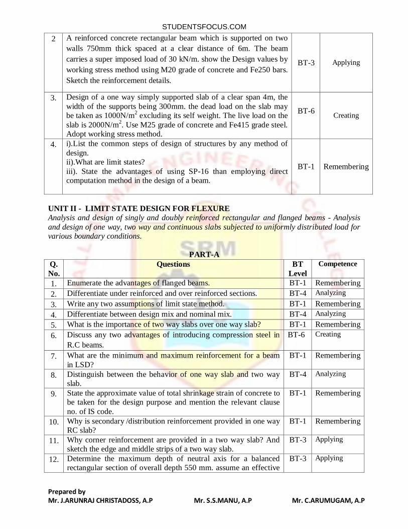
2 A reinforced concrete rectangular beam which is supported on two
walls 750mm thick spaced at a clear distance of 6m. The beam
carries a super imposed load of 30 kN/m. show the Design values by
working stress method using M20 grade of concrete and Fe250 bars.
Sketch the reinforcement details.
BT-3 Applying
3. Design of a one way simply supported slab of a clear span 4m, the
width of the supports being 300mm. the dead load on the slab may be taken as 1000N/m
2 excluding its self weight. The live load on the
slab is 2000N/m2. Use M25 grade of concrete and Fe415 grade steel.
Adopt working stress method.
BT-6
Creating
4. i).List the common steps of design of structures by any method of
design. ii).What are limit states?
iii). State the advantages of using SP-16 than employing direct computation method in the design of a beam.
BT-1 Remembering
UNIT II - LIMIT STATE DESIGN FOR FLEXURE
Analysis and design of singly and doubly reinforced rectangular and flanged beams - Analysis
and design of one way, two way and continuous slabs subjected to uniformly distributed load for various boundary conditions.
PART-A
Q.
No.
Questions BT
Level
Competence
1. Enumerate the advantages of flanged beams. BT-1 Remembering
2. Differentiate under reinforced and over reinforced sections. BT-4 Analyzing
3. Write any two assumptions of limit state method. BT-1 Remembering
4. Differentiate between design mix and nominal mix. BT-4 Analyzing
5. What is the importance of two way slabs over one way slab? BT-1 Remembering
6. Discuss any two advantages of introducing compression steel in
R.C beams.
BT-6 Creating
7. What are the minimum and maximum reinforcement for a beam
in LSD?
BT-1 Remembering
8. Distinguish between the behavior of one way slab and two way slab.
BT-4 Analyzing
9. State the approximate value of total shrinkage strain of concrete to be taken for the design purpose and mention the relevant clause
no. of IS code.
BT-1 Remembering
10. Why is secondary /distribution reinforcement provided in one way RC slab?
BT-1 Remembering
11. Why corner reinforcement are provided in a two way slab? And sketch the edge and middle strips of a two way slab.
BT-3 Applying
12. Determine the maximum depth of neutral axis for a balanced rectangular section of overall depth 550 mm. assume an effective
BT-3 Applying
STUDENTSFOCUS.COM
Prepared by Mr. J.ARUNRAJ CHRISTADOSS, A.P Mr. S.S.MANU, A.P Mr. C.ARUMUGAM, A.P
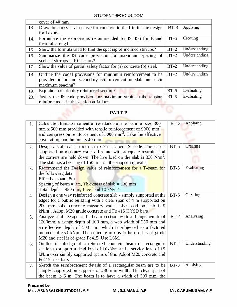
cover of 40 mm.
13. Draw the stress-strain curve for concrete in the Limit state design for flexure.
BT-3 Applying
14. Formulate the expressions recommended by IS 456 for E and flexural strength.
BT-6 Creating
15. Show the formula used to find the spacing of inclined stirrups? BT-2 Understanding
16. Summarize the IS code provision for maximum spacing of vertical stirrups in RC beams?
BT-2 Understanding
17. Show the value of partial safety factor for (a) concrete (b) steel. BT-2 Understanding
18. Outline the codal provisions for minimum reinforcement to be provided main and secondary reinforcement in slab and their
maximum spacing?
BT-2 Understanding
19. Explain about doubly reinforced section? BT-5 Evaluating
20. Justify the IS code provision for maximum strain in the tension reinforcement in the section at failure.
BT-5 Evaluating
PART-B
1. Calculate ultimate moment of resistance of the beam of size 300
mm x 500 mm provided with tensile reinforcement of 9000 mm2
and compression reinforcement of 3000 mm2. Take the effective
cover at top and bottom is 40 mm.
BT-3 Applying
2. Design a slab over a room 5 m x 7 m as per I.S. code. The slab is supported on masonry walls all round with adequate restraint and
the corners are held down. The live load on the slab is 330 N/m2.
The slab has a bearing of 150 mm on the supporting walls.
BT-6 Creating
3. Recommend the Design value of reinforcement for a T-beam for the following data:
Effective span : 8m Spacing of beam = 3m, Thickness of slab = 130 mm
Total depth = 450 mm, Live load 10 kN/m2.
BT-5 Evaluating
4. Design a one way reinforced concrete slab - simply supported at the edges for a public building with a clear span of 4 m supported on
200 mm solid concrete masonry walls. Live load on slab is 5 kN/m
2. Adopt M20 grade concrete and Fe 415 HYSD bars.
BT-6 Creating
5. Analyze and Design a T- beam section with a flange width of 1200mm, a flange depth of 100 mm, a web width of 250 mm and
an effective depth of 500 mm, which is subjected to a factored moment of 550 kNm. The concrete mix is to be used is of grade
M20 and steel is of grade Fe415. Use LSM.
BT-4 Analyzing
6. Outline the design of a reinfored concrete beam of rectangular section to support a dead load of 10kN/m and a service load of 15
kN/m over simply supported spans of 8m. Adopt M20 concrete and Fe415 steel bars.
BT-2 Understanding
7. Sketch the reinforcement details of a rectangular beam are to be simply supported on supports of 230 mm width. The clear span of
the beam is 6 m. The beam is to have a width of 300 mm, the
BT-3 Applying
STUDENTSFOCUS.COM
Prepared by Mr. J.ARUNRAJ CHRISTADOSS, A.P Mr. S.S.MANU, A.P Mr. C.ARUMUGAM, A.P
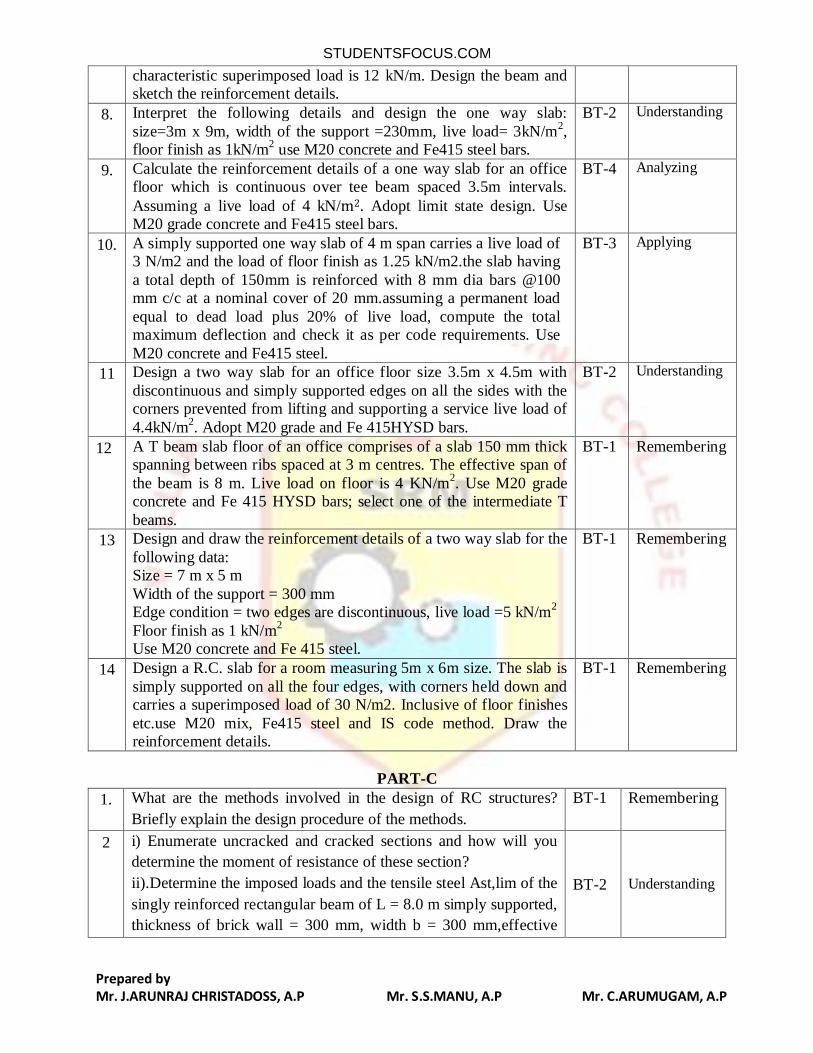
characteristic superimposed load is 12 kN/m. Design the beam and sketch the reinforcement details.
8. Interpret the following details and design the one way slab:
size=3m x 9m, width of the support =230mm, live load= 3kN/m2,
floor finish as 1kN/m2 use M20 concrete and Fe415 steel bars.
BT-2 Understanding
9. Calculate the reinforcement details of a one way slab for an office floor which is continuous over tee beam spaced 3.5m intervals.
Assuming a live load of 4 kN/m2. Adopt limit state design. Use M20 grade concrete and Fe415 steel bars.
BT-4 Analyzing
10. A simply supported one way slab of 4 m span carries a live load of 3 N/m2 and the load of floor finish as 1.25 kN/m2.the slab having
a total depth of 150mm is reinforced with 8 mm dia bars @100 mm c/c at a nominal cover of 20 mm.assuming a permanent load
equal to dead load plus 20% of live load, compute the total maximum deflection and check it as per code requirements. Use
M20 concrete and Fe415 steel.
BT-3 Applying
11 Design a two way slab for an office floor size 3.5m x 4.5m with
discontinuous and simply supported edges on all the sides with the corners prevented from lifting and supporting a service live load of
4.4kN/m2. Adopt M20 grade and Fe 415HYSD bars.
BT-2 Understanding
12 A T beam slab floor of an office comprises of a slab 150 mm thick spanning between ribs spaced at 3 m centres. The effective span of
the beam is 8 m. Live load on floor is 4 KN/m2. Use M20 grade
concrete and Fe 415 HYSD bars; select one of the intermediate T
beams.
BT-1
Remembering
13 Design and draw the reinforcement details of a two way slab for the
following data: Size = 7 m x 5 m
Width of the support = 300 mm Edge condition = two edges are discontinuous, live load =5 kN/m
2
Floor finish as 1 kN/m2
Use M20 concrete and Fe 415 steel.
BT-1
Remembering
14 Design a R.C. slab for a room measuring 5m x 6m size. The slab is
simply supported on all the four edges, with corners held down and carries a superimposed load of 30 N/m2. Inclusive of floor finishes
etc.use M20 mix, Fe415 steel and IS code method. Draw the reinforcement details.
BT-1
Remembering
PART-C
1. What are the methods involved in the design of RC structures?
Briefly explain the design procedure of the methods.
BT-1
Remembering
2 i) Enumerate uncracked and cracked sections and how will you
determine the moment of resistance of these section?
ii).Determine the imposed loads and the tensile steel Ast,lim of the
singly reinforced rectangular beam of L = 8.0 m simply supported,
thickness of brick wall = 300 mm, width b = 300 mm,effective
BT-2 Understanding
STUDENTSFOCUS.COM
Prepared by Mr. J.ARUNRAJ CHRISTADOSS, A.P Mr. S.S.MANU, A.P Mr. C.ARUMUGAM, A.P
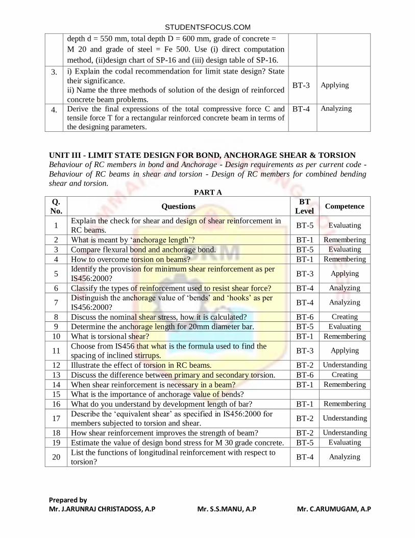
depth d = 550 mm, total depth D = 600 mm, grade of concrete =
M 20 and grade of steel = Fe 500. Use (i) direct computation
method, (ii)design chart of SP-16 and (iii) design table of SP-16.
3. i) Explain the codal recommendation for limit state design? State
their significance. ii) Name the three methods of solution of the design of reinforced
concrete beam problems.
BT-3 Applying
4. Derive the final expressions of the total compressive force C and
tensile force T for a rectangular reinforced concrete beam in terms of
the designing parameters.
BT-4
Analyzing
UNIT III - LIMIT STATE DESIGN FOR BOND, ANCHORAGE SHEAR & TORSION
Behaviour of RC members in bond and Anchorage - Design requirements as per current code -
Behaviour of RC beams in shear and torsion - Design of RC members for combined bending shear and torsion.
PART A
Q.
No. Questions
BT
Level Competence
1 Explain the check for shear and design of shear reinforcement in RC beams.
BT-5 Evaluating
2 What is meant by ‘anchorage length’? BT-1 Remembering
3 Compare flexural bond and anchorage bond. BT-5 Evaluating
4 How to overcome torsion on beams? BT-1 Remembering
5 Identify the provision for minimum shear reinforcement as per
IS456:2000? BT-3 Applying
6 Classify the types of reinforcement used to resist shear force? BT-4 Analyzing
7 Distinguish the anchorage value of ‘bends’ and ‘hooks’ as per
IS456:2000? BT-4 Analyzing
8 Discuss the nominal shear stress, how it is calculated? BT-6 Creating
9 Determine the anchorage length for 20mm diameter bar. BT-5 Evaluating
10 What is torsional shear? BT-1 Remembering
11 Choose from IS456 that what is the formula used to find the spacing of inclined stirrups.
BT-3 Applying
12 Illustrate the effect of torsion in RC beams. BT-2 Understanding
13 Discuss the difference between primary and secondary torsion. BT-6 Creating
14 When shear reinforcement is necessary in a beam? BT-1 Remembering
15 What is the importance of anchorage value of bends?
16 What do you understand by development length of bar? BT-1 Remembering
17 Describe the ‘equivalent shear’ as specified in IS456:2000 for members subjected to torsion and shear.
BT-2 Understanding
18 How shear reinforcement improves the strength of beam? BT-2 Understanding
19 Estimate the value of design bond stress for M 30 grade concrete. BT-5 Evaluating
20 List the functions of longitudinal reinforcement with respect to torsion?
BT-4 Analyzing
STUDENTSFOCUS.COM
Prepared by Mr. J.ARUNRAJ CHRISTADOSS, A.P Mr. S.S.MANU, A.P Mr. C.ARUMUGAM, A.P
PART B
Q. No. Questions BT
Level
Competence
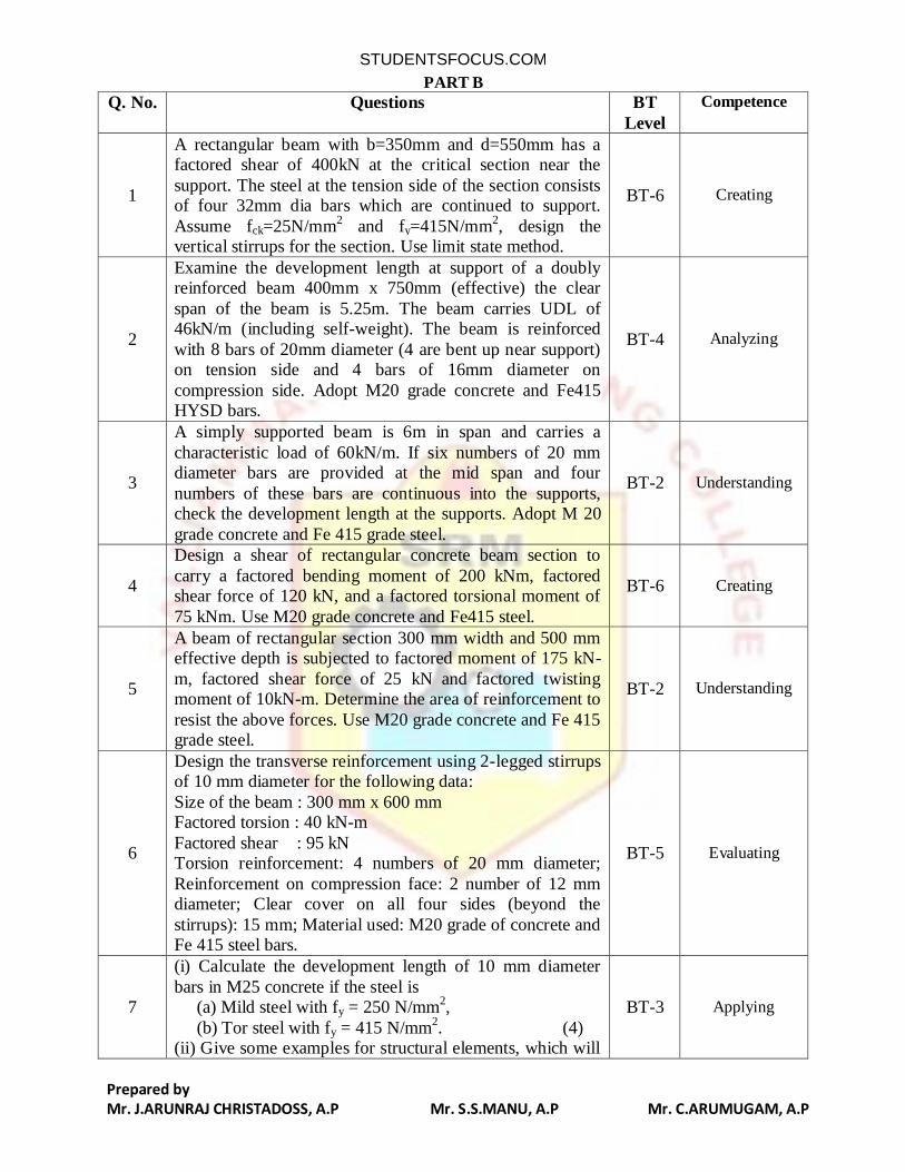
1
A rectangular beam with b=350mm and d=550mm has a factored shear of 400kN at the critical section near the
support. The steel at the tension side of the section consists of four 32mm dia bars which are continued to support.
Assume fck=25N/mm2 and fy=415N/mm
2, design the
vertical stirrups for the section. Use limit state method.
BT-6 Creating
2
Examine the development length at support of a doubly reinforced beam 400mm x 750mm (effective) the clear
span of the beam is 5.25m. The beam carries UDL of 46kN/m (including self-weight). The beam is reinforced
with 8 bars of 20mm diameter (4 are bent up near support) on tension side and 4 bars of 16mm diameter on
compression side. Adopt M20 grade concrete and Fe415 HYSD bars.
BT-4 Analyzing
3
A simply supported beam is 6m in span and carries a
characteristic load of 60kN/m. If six numbers of 20 mm diameter bars are provided at the mid span and four
numbers of these bars are continuous into the supports, check the development length at the supports. Adopt M 20
grade concrete and Fe 415 grade steel.
BT-2 Understanding
4
Design a shear of rectangular concrete beam section to
carry a factored bending moment of 200 kNm, factored shear force of 120 kN, and a factored torsional moment of
75 kNm. Use M20 grade concrete and Fe415 steel.
BT-6 Creating
5
A beam of rectangular section 300 mm width and 500 mm effective depth is subjected to factored moment of 175 kN-
m, factored shear force of 25 kN and factored twisting moment of 10kN-m. Determine the area of reinforcement to
resist the above forces. Use M20 grade concrete and Fe 415 grade steel.
BT-2 Understanding
6
Design the transverse reinforcement using 2-legged stirrups of 10 mm diameter for the following data:
Size of the beam : 300 mm x 600 mm Factored torsion : 40 kN-m
Factored shear : 95 kN Torsion reinforcement: 4 numbers of 20 mm diameter;
Reinforcement on compression face: 2 number of 12 mm diameter; Clear cover on all four sides (beyond the
stirrups): 15 mm; Material used: M20 grade of concrete and Fe 415 steel bars.
BT-5 Evaluating
7
(i) Calculate the development length of 10 mm diameter
bars in M25 concrete if the steel is (a) Mild steel with fy = 250 N/mm
2,
(b) Tor steel with fy = 415 N/mm2. (4)
(ii) Give some examples for structural elements, which will
BT-3 Applying
STUDENTSFOCUS.COM
Prepared by Mr. J.ARUNRAJ CHRISTADOSS, A.P Mr. S.S.MANU, A.P Mr. C.ARUMUGAM, A.P
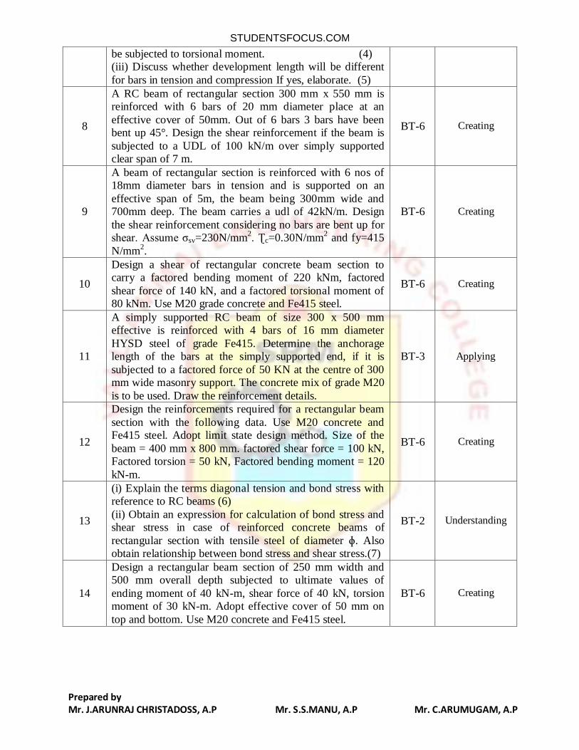
be subjected to torsional moment. (4) (iii) Discuss whether development length will be different
for bars in tension and compression If yes, elaborate. (5)
8
A RC beam of rectangular section 300 mm x 550 mm is reinforced with 6 bars of 20 mm diameter place at an
effective cover of 50mm. Out of 6 bars 3 bars have been bent up 45°. Design the shear reinforcement if the beam is
subjected to a UDL of 100 kN/m over simply supported clear span of 7 m.
BT-6 Creating
9
A beam of rectangular section is reinforced with 6 nos of 18mm diameter bars in tension and is supported on an
effective span of 5m, the beam being 300mm wide and 700mm deep. The beam carries a udl of 42kN/m. Design
the shear reinforcement considering no bars are bent up for shear. Assume σsv=230N/mm
2. Ʈc=0.30N/mm
2 and fy=415
N/mm2.
BT-6 Creating
10
Design a shear of rectangular concrete beam section to carry a factored bending moment of 220 kNm, factored
shear force of 140 kN, and a factored torsional moment of 80 kNm. Use M20 grade concrete and Fe415 steel.
BT-6 Creating
11
A simply supported RC beam of size 300 x 500 mm effective is reinforced with 4 bars of 16 mm diameter
HYSD steel of grade Fe415. Determine the anchorage length of the bars at the simply supported end, if it is
subjected to a factored force of 50 KN at the centre of 300 mm wide masonry support. The concrete mix of grade M20
is to be used. Draw the reinforcement details.
BT-3 Applying
12
Design the reinforcements required for a rectangular beam
section with the following data. Use M20 concrete and Fe415 steel. Adopt limit state design method. Size of the
beam = 400 mm x 800 mm. factored shear force = 100 kN, Factored torsion = 50 kN, Factored bending moment = 120
kN-m.
BT-6 Creating
13
(i) Explain the terms diagonal tension and bond stress with reference to RC beams (6)
(ii) Obtain an expression for calculation of bond stress and shear stress in case of reinforced concrete beams of
rectangular section with tensile steel of diameter ɸ. Also obtain relationship between bond stress and shear stress.(7)
BT-2 Understanding
14
Design a rectangular beam section of 250 mm width and 500 mm overall depth subjected to ultimate values of
ending moment of 40 kN-m, shear force of 40 kN, torsion moment of 30 kN-m. Adopt effective cover of 50 mm on
top and bottom. Use M20 concrete and Fe415 steel.
BT-6 Creating
STUDENTSFOCUS.COM
Prepared by Mr. J.ARUNRAJ CHRISTADOSS, A.P Mr. S.S.MANU, A.P Mr. C.ARUMUGAM, A.P
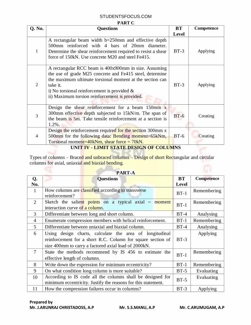
PART C
Q. No. Questions BT
Level
Competence
1
A rectangular beam width b=250mm and effective depth 500mm reinforced with 4 bars of 20mm diameter.
Determine the shear reinforcement required to resist a shear force of 150kN. Use concrete M20 and steel Fe415.
BT-3 Applying
2
A rectangular RCC beam is 400x900mm in size. Assuming the use of grade M25 concrete and Fe415 steel, determine
the maximum ultimate torsional moment at the section can take it.
i) No torsional reinforcement is provided & ii) Maximum torsion reinforcement is provided.
BT-3 Applying
3
Design the shear reinforcement for a beam 150mm x
300mm effective depth subjected to 15kN/m. The span of the beam is 5m. Take tensile reinforcement at a section is
1.2%.
BT-6 Creating
4
Design the reinforcement required for the section 300mm x 500mm for the following data: Bending moment=65kNm,
Torsional moment=40kNm, shear force = 70kN.
BT-6 Creating
UNIT IV - LIMIT STATE DESIGN OF COLUMNS
Types of columns – Braced and unbraced columns – Design of short Rectangular and circular columns for axial, uniaxial and biaxial bending.
PART-A
Q.
No.
Questions BT
Level
Competence
1 How columns are classified according to transverse reinforcement?
BT-1 Remembering
2 Sketch the salient points on a typical axial – moment
interaction curve of a column. BT-1
Remembering
3 Differentiate between long and short column. BT-4 Analysing
4 Enumerate compression members with helical reinforcement. BT-1 Remembering
5 Differentiate between uniaxial and biaxial column. BT-4 Analysing
6 Using design charts, calculate the area of longitudinal
reinforcement for a short R.C. Column for square section of
size 400mm to carry a factored axial load of 2000kN.
BT-3
Applying
7 State the methods recommend by IS 456 to estimate the
effective length of columns. BT-1
Remembering
8 Write down the expression for minimum eccentricity? BT-1 Remembering
9 On what condition long column is more suitable? BT-5 Evaluating
10 According to IS code all the columns shall be designed for
minimum eccentricity. Justify the reasons for this statement. BT-5
Evaluating
11 How the compression failures occur in columns? BT-3 Applying
STUDENTSFOCUS.COM
Prepared by Mr. J.ARUNRAJ CHRISTADOSS, A.P Mr. S.S.MANU, A.P Mr. C.ARUMUGAM, A.P
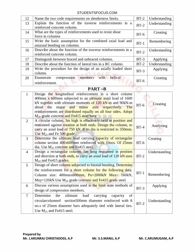
12 Name the two code requirements on slenderness limits. BT-2 Understanding
13 Explain the function of the traverse reinforcements in a reinforced concrete column.
BT-2 Understanding
14 What are the types of reinforcements used to resist shear force in columns
BT-6 Creating
15 Write the basic assumption for the combined axial load and
uniaxial bending on columns. BT-1
Remembering
16 Describe about the function of the traverse reinforcements in a
reinforced concrete column. BT-2
Understanding
17 Distinguish between braced and unbraced columns. BT-3 Applying
18 Describe about the function of lateral ties in a RC column. BT-2 Understanding
19 Write the procedure for the design of an axially loaded short
column. BT-3
Applying
20 Enumerate compression members with helical
reinforcement. BT-6
Creating
PART –B
1 Design the longitudinal reinforcement in a short column 400mm x 600mm subjected to an ultimate axial load of 1600
kN together with ultimate moments of 120 kN-m and 90kN-m about the major and minor axis respectively. The
reinforcements are distributed equally on all four sides. Adopt M20 grade concrete and Fe415 steel bars.
BT-6
Creating
2 A circular column, 3m high is effectively held in position and
restrained against rotation at both ends. Design the column, to carry an axial load of 750 kN, if its dia is restricted to 350mm.
Use M25 and Fe 500 grade.
BT-4
Analysing
3 Determine the ultimate load carrying capacity of rectangular
column section 400x600mm reinforced with 10nos. Of 25mm dia. Use M25 concrete and Fe415 steel.
BT-6 Creating
4 Design a rectangular column, 5m long restrained in position
and direction at both ends, to carry an axial load of 120 kN.uses M20 and Fe415 grades.
BT-2 Understanding
5 Design of short column subjected to biaxial bending. Determine
the reinforcement for a short column for the following data.
Column size: 400mmx600mm, Pu=2000kN Mux= 160kN,
Muy=120kN.Use M20 grade concrete and Fe415 grade steel.
BT-1
Remembering
6 Discuss various assumptions used in the limit state methods of
design of compression members. BT-3
Applying
7 Determine the ultimate load carrying capacity of
circularcolumnof section500mm diameter reinforced with 8
no.s of 25mm diameter bars adequately tied with lateral ties.
Use M25 and Fe415 steel.
BT-2
Understanding
STUDENTSFOCUS.COM
Prepared by Mr. J.ARUNRAJ CHRISTADOSS, A.P Mr. S.S.MANU, A.P Mr. C.ARUMUGAM, A.P
8 Design the reinforcement in short column 400x600mm subjected to an ultimate axial load of 1600kN together with
ultimate moments of 120kNm and 90kNm about the major and minor axis respectively. Use M20 grade concrete and Fe415
grade steel.
BT-3
Applying
9 Design a biaxial eccentric loaded braced circular column
deforming in single curvature for the following data: Ultimate
load=200kNUltimate moment in longer direction at bottom
Mux1=178 kNm and at top Mux1= 128kNm.Ultimate moment
in shorter direction at bottom Muy1= 108 kNm and at top
Muy2= 88kNm. Unsupported length of column = 9m.Effective
length in long direction lex=8m.Effective length in shorter
direction ley= 5.8m.Diameter of column = 550mm.Use
M25&Fe415.
BT-3
Applying
10 Design the reinforcement in a circular column of diameter
350mm with helical reinforcement of 8mm diameter to support a factored load of 1400kN. The column has an unsupported
length of 3.5 m and is braced against side sway. Adopt M20 grade concrete and Fe415 steel bars.
BT-
2
Understanding
11 A circular column, 4.6m high is effectively held in position at
both ends and restrained against rotation at one end onlyto carry
an axial load of 1200kN, if its dia is restricted to 450mm. Use
M20 and Fe415 grades.
BT-1
Remembering
12 Design a short column subjected to biaxial bending. Determine the reinforcement fora short column for the following data.
Column size: 400mmx600mm, Pu=200kN Mux: 160kN, Muy=120kN.Use M20 grade concrete and Fe415 grade steel.
BT-5
Evaluating
13 Design the reinforcement required for a column which is
restrained against sway using the following data.
Size of column=530x450mm, leff=6.6m, unsupported
length=7.70m.
Factored load =1600kN. Factored moment about major axis
=45kNm at top and 30kNm at bottom. Factored moment about
minor axis=35kNm at top and 20kNm at bottom. Use M25 grade
concrete and Fe 500 grade HYSD bars. Column is bent in
double curvature and reinforcement is distributed equally on all
the four sides of the section.
BT-4
Analysing
14 Design the reinforcements required for a column which is
restrained against sway using the following data. Size of
column =530x450mm, leff=6.6m unsupported length = 7.70m.
Factored load =1600kN.factored moment about major axis =
45kNm at top and 30knm at bottom. Factored moment about
minor axis =35kNm at top and 20kNm at bottom. Use M25
grade concrete and Fe500 grade HYSD bars. Column is bent in
BT-4
Analysing
STUDENTSFOCUS.COM
Prepared by Mr. J.ARUNRAJ CHRISTADOSS, A.P Mr. S.S.MANU, A.P Mr. C.ARUMUGAM, A.P
double curvature and reinforcement is distributed equally on all
the four sides of the section.
PART-C
1.
A rectangular column of effective height 4m is subjected to a
load of 1800kN and bending moment of 100 kNm about major axis of the column. Design a suitable section for the column so
that the width should not exceed 400mm.Use M25 concrete and Fe415 steel
BT-6
Creating
2. Design a square column subjected to an ultimate axial load of 1000kN.Consider concrete grade M20 and steel of grade Fe415.
BT-1
Remembering
3. Determine the reinforcements to be provided in a short RC
column given the following data, by limit state method. (i) Size of column = 300 x 600mm
(ii) Factored load = 1200kN (iii) Factored moments, Mux = 160kNm&Muy = 80kNm
BT-
5
Evaluating
4. Design a uniaxial spiral circular short column with details as
given below. (i) Factored axial load = 300kN
(ii) Factored bending moment = 80kNm (iii) Column size = 400mm
Use M20 and Fe415 combination
BT-
3
Applying
UNIT V - LIMIT STATE DESIGN OF FOOTING
Design of wall footing – Design of axially and eccentrically loaded rectangular pad and sloped footings – Design of combined rectangular footing for two columns only.
PART – A Q.
No.
Questions BT
Level
Competence
1. How is the main steel distributed in wall footings and two way
rectangular footings? BT-5
Evaluating
2. What are the factors that influence the selection of number of
lifting and hoisting locations of a long beam during its erection process?
BT-1 Remembering
3. Define punching shear. BT-1 Remembering
4. What is the main advantage of combined footing? BT-1 Remembering
5. When you need a combined footing? BT-1 Remembering
6. Why check for transfer of load at the base of the column over
footing is done? BT-2
Understanding
7. Write any two situations in which combined footings are preferred to isolated footings.
BT-3 Applying
8. Explain about eccentric loading on a footing? BT-4 Analysing
9. Sketch the placement of steel in rectangular footing with a non- BT-3 Applying
STUDENTSFOCUS.COM
Prepared by Mr. J.ARUNRAJ CHRISTADOSS, A.P Mr. S.S.MANU, A.P Mr. C.ARUMUGAM, A.P
central load.
10. Draw a neat sketch of a masonry footing. BT-3 Applying
11. What is slenderness ratio for a masonry wall? State the
maximum values? BT-1
Remembering
12. Compare the behaviour of tied and spirally reinforced column. BT-4 Analysing
13. Under what circumstances a trapezoidal footing become
necessary? BT-2
Understanding
14. How do you classify one-way footing and two-way footing in foundation?
BT-2 Understanding
15. Sketch the reinforcement detailing for the cantilever slab. BT-3 Applying
16. On what circumstances combined rectangular footings are suitable?
BT-2 Understanding
17. What is meant by proportioning of footing? BT-1 Remembering
18. Enumerate axially loaded column. BT-4 Analysing
19. Compare one way and two way shear in footing. BT-6 Creating
20. Compare punching shear and normal shear in RCC footing. BT-6 Creating
PART –B
1. Design a suitable footing for a 500 mm x 500 mm square column
transferring 100kN axial load and a moment of 35kN-m.The safe bearing capacity of soil is 190 kN/ m
2.Use M20 concrete and Fe415
steel. Adopt limit state design method.
BT-2
Understandi
ng
2. A rectangular RCC column of size 400 mm x 600 mm carrying an
axial load of 1800kN.If the safe bearing capacity of the soil is
150kN/m2.Design a suitable footing. Use M25 concrete and Fe415
BT-3
Applying
3. Draw the shear force and bending moment diagrams and design the
20 mm diameter bars as top steel for maximum hogging moment
for a RC rectangular combined footing using the following data:
Centre to centre distance between the column is 4m.Each column
is square in shape with 400 mm side. Each column carries an axial
load at service state = 1200kN.The projection of footing parallel to
the length beyond the axis of each column is 1m.The limiting
bearing capacity of soil is 440kN/m2.Use M20 grade and Fe 415
steel bars.
BT-3
Applying
4. A square column of size 400mm carries a service load of 600kN.
Design an isolated footing for the column by limit state method, if
the safe bearing capacity of the soil is 250kN/m2. Use M20 concrete
and Fe415 steel.
BT-3
Applying
5. Design a rectangular isolated footing of uniform thickness for R.C.
column bearing a vertical load of 600kN, and having a base size of
400 x 600 mm. The SBC of soil is 120 kN/m2. Use M25grade
concrete and M.S grade‐I bars. Draw the reinforcement details.
BT-5
Evaluating
6. 7. Sketch the standard detailing of the following:
(i) Two spans one‐way continuous slab with curtailment details (7) BT-2
Understandi
STUDENTSFOCUS.COM
Prepared by Mr. J.ARUNRAJ CHRISTADOSS, A.P Mr. S.S.MANU, A.P Mr. C.ARUMUGAM, A.P
(ii) Curtailment details in a tapered cantilever beam.(6) ng
7. A rectangular column of size 300x450mm transmits a limit state
load of 600kN at an eccentricity of 150mm about the major axis.
Design a suitable isolated footing for the column by the limit state
concept. Safe capacity of soil is 200kN/m2. Use M30grade of
concrete and Fe415 grade of steel.
BT-2
Understandi
ng
8. Design a suitable footing for a R.C. column of size 300x500mm.
Supporting a factored axial load of 1500kN. Assume safe bearing capacity of soil as 200kN/m
2. Adopt M20 grade of concrete and
Fe415 grade of steel. Sketch the details at reinforcements in footings.
BT-2
Understandi
ng
9. (i) Write down the different types of footings and their suitability.
(ii) Enumerate the procedure for the design of combinedrectangular footing for two columns only.
BT-1
Rememberi
ng
10. Design a isolated footing for a square column, 450 mm × 450
mm,reinforced with 8 numbers of 25mmdia bars, and carrying a
service load of 2300 kN.Assume soil with a safe bearing capacity (gross) of 300 kN/m
2 at a depth of 1.5 m below ground. Assume
M20 grade concrete and Fe415grade steel for the footing, and M25 grade concrete and Fe415 grade steel for the column.
BT-1
Rememberi
ng
11. Design an isolated square footing for a column 500mm x 500m
transmitting a load of 600kN and a moment of 30 kN‐m. The SBC
of soil is 1230 kN/m2 . Use M20 grade concrete and M.S. grade –I
bars. Draw the reinforcement details.
BT-1
Rememberi
ng
12. A 230 mm thick masonry wall is to be provided with reinforced
concrete footing on a site having soil with SBC, unit weight and
angle of repose of 125 kN/m2, 17.5 kN/m
3and 30˚ respectively, use
M20 grade of concrete and HYSD steel bars of grade Fe415, design the footing when the wall supports at service state, a load of 150
kN/m length.
BT-1
Rememberi
ng
13. A rectangular column 600 x 400 mm carries a load of 800 kN. Design a rectangular footing to support the column. The safe
bearing capacity of the soil is 200 kN/m2.
Use M20 grade concrete.
BT-3
Applying
14. Design a combined footing for the two columns at a multi‐storey building. The columns of size 400mmx400mm transmit a working
load of 300kN each and they are spaced at 5m c/c .The safe bearing capacity of soil at site is 200kN/m
2. Adopt M20 grade concrete and
Fe415 grade steel. Sketch the details of reinforcements in the combined footing.
BT-1
Rememberi
ng
STUDENTSFOCUS.COM
Prepared by Mr. J.ARUNRAJ CHRISTADOSS, A.P Mr. S.S.MANU, A.P Mr. C.ARUMUGAM, A.P
PART-C
1.
Design a reinforced concrete footing for a 345 mm thick masonry
wall which supports a characteristic load of 250 kN/m including self weight. Assume safe bearing capacity of soil is 150kN/m
2at a
depth of 1.2m below ground level. Assume M20 and Fe415 steel used.
BT-3 Applying
2. A solid footing has to transfer a dead load of 900kN and an
imposed load of 500kN for a square column of size 400mm.Assume safe bearing capacity of soil as 200kN/m
2.
Design a square footing to support the above column.
BT-5 Evaluating
3. A rectangular RC column of size 300mm x 450mm carrying an
axial load of 1500kN. If the safe bearing capacity of the soil is180 kN/m
2, design a suitable footing. Consider M25 grade concrete and
Fe415 grade steel are used.
BT-6 Creating
4. A reinforced concrete column of 500 x 650 carries the axial dead load of 670 kN, axial imposed load of 330kN and dead load
momentof 66kNm, imposed load of 34kNm. If the SBC of soil is 150kN/m
2and use concrete grade of M25 and steel grade of Fe415.
The foundation has to be designed to resist the ultimate moment and shear resulting from these loads.
BT-2 Understanding
STUDENTSFOCUS.COM