Vacuum Switching Technology and Components for … · Vacuum Switching Technology and Components...
36
Catalog HG 11.01 Edition 2016 siemens.com/mediumvoltage Vacuum Switching Technology and Components for Medium Voltage Your Guide
Transcript of Vacuum Switching Technology and Components for … · Vacuum Switching Technology and Components...

Catalog
HG 11.01
Edition 2016
siemens.com/mediumvoltage
Vacuum Switching Technology and Components for Medium Voltage Your Guide
2 Vacuum Switching Technology and Components for Medium Voltage · Siemens HG 11.01 · 2016
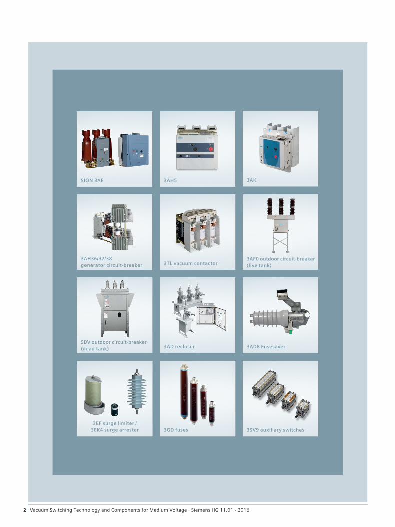
3AH36/37/38 generator circuit-breaker
3AK
3AD recloser
3EF surge limiter / 3EK4 surge arrester
3AF0 outdoor circuit-breaker (live tank)3TL vacuum contactor
SDV outdoor circuit-breaker (dead tank) 3AD8 Fusesaver
3GD fuses 3SV9 auxiliary switches
3AH5SION 3AE
3Vacuum Switching Technology and Components for Medium Voltage · Siemens HG 11.01 · 2016
The products and systems described in this catalog are manufactured and sold according to a certified management system (acc. to ISO 9001, ISO 14001 and BS OHSAS 18001).
Vacuum Switching Technology and Components for Medium VoltageMedium-Voltage Equipment
Catalog HG 11.01 · 2016
Invalid: Catalog HG 11.01 · 2007
www.siemens.com/mediumvoltage
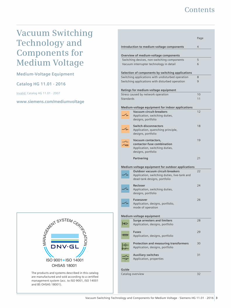
Contents
Page
Introduction to medium-voltage components 4
Overview of medium-voltage componentsSwitching devices, non-switching components 5Vacuum interrupter technology in detail 6
Selection of components by switching applicationsSwitching applications with undisturbed operation 8Switching applications with disturbed operation 9
Ratings for medium-voltage equipmentStress caused by network operation 10Standards 11
Medium-voltage equipment for indoor applications Vacuum circuit-breakers
Application, switching duties, designs, portfolio
12
Switch-disconnectors Application, quenching principle, designs, portfolio
18
Vacuum contactors, contactor-fuse combination Application, switching duties, designs, portfolio
19
Partnering 21
Medium-voltage equipment for outdoor applications Outdoor vacuum circuit-breakers
Application, switching duties, live-tank and dead-tank designs, portfolio
22
Recloser Application, switching duties, designs, portfolio
24
Fusesaver Application, designs, portfolio, mode of operation
26
Medium-voltage equipment Surge arresters and limiters
Application, designs, portfolio28
Fuses Application, designs, portfolio
29
Protection and measuring transformers Application, designs, portfolio
30
Auxiliary switches Application, properties
31
GuideCatalog overview 32
4 Vacuum Switching Technology and Components for Medium Voltage · Siemens HG 11.01 · 2016
Introduction to medium-voltage components
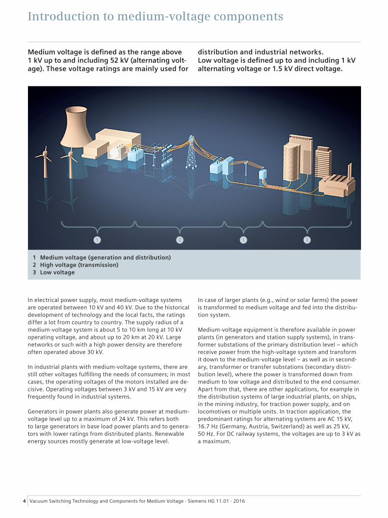
Medium voltage is defined as the range above 1 kV up to and including 52 kV (alternating volt-age). These voltage ratings are mainly used for
distribution and industrial networks. Low voltage is defined up to and including 1 kV alternating voltage or 1.5 kV direct voltage.
In electrical power supply, most medium-voltage systems are operated between 10 kV and 40 kV. Due to the historical development of technology and the local facts, the ratings differ a lot from country to country. The supply radius of a medium-voltage system is about 5 to 10 km long at 10 kV operating voltage, and about up to 20 km at 20 kV. Large networks or such with a high power density are therefore often operated above 30 kV.
In industrial plants with medium-voltage systems, there are still other voltages fulfilling the needs of consumers; in most cases, the operating voltages of the motors installed are de-cisive. Operating voltages between 3 kV and 15 kV are very frequently found in industrial systems.
Generators in power plants also generate power at medium-voltage level up to a maximum of 24 kV. This refers both to large generators in base load power plants and to genera-tors with lower ratings from distributed plants. Renewable energy sources mostly generate at low-voltage level.
In case of larger plants (e.g., wind or solar farms) the power is transformed to medium voltage and fed into the distribu-tion system.
Medium-voltage equipment is therefore available in power plants (in generators and station supply systems), in trans-former substations of the primary distribution level – which receive power from the high-voltage system and transform it down to the medium-voltage level – as well as in second-ary, transformer or transfer substations (secondary distri-bution level), where the power is transformed down from medium to low voltage and distributed to the end consumer. Apart from that, there are other applications, for example in the distribution systems of large industrial plants, on ships, in the mining industry, for traction power supply, and on locomotives or multiple units. In traction application, the predominant ratings for alternating systems are AC 15 kV, 16.7 Hz (Germany, Austria, Switzerland) as well as 25 kV, 50 Hz. For DC railway systems, the voltages are up to 3 kV as a maximum.
1 Medium voltage (generation and distribution)2 High voltage (transmission)3 Low voltage
1 2 1 3
5Vacuum Switching Technology and Components for Medium Voltage · Siemens HG 11.01 · 2016
Overview of medium-voltage componentsSwitching devices, non-switching components
The term medium-voltage equipment summarizes all prod-ucts and components required for operation of medium-voltage systems. It comprises switching and non-switching components. Depending on the case of application, these devices are installed in grids as independent products, or as components inside a switchgear assembly.
RequirementsWhen the devices operate in grids, they are subjected to a number of stresses that are decisive for the selection and dimensioning of the devices. The main stresses are briefly summarized in the following, whereby only a limited selec-tion of these values is relevant depending on the type of device:
• Dielectric strength in normal operation. This comprises both the operating voltage (as a rated value including arising voltage fluctuations) and overvoltages (switching and lightning overvoltages)
• Conducting the current – the normal current, continuous-ly; overcurrents, temporarily; fault currents up to short-circuit currents, momentarily
• Making or breaking the current while dominating the aris-ing transient processes, whereby only a part of the listed currents can be switched depending on the type of device – Normal current – Fault currents – Currents with a (temporarily) special characteristic, such
as capacitive currents, inductive currents, high-frequen-cy transient currents
• Establishing a safe, i.e. surge-proof isolating distance in the open state. This is requested by the standard as a precondition for isolating and subsequent working on the isolated section. This does not mean the operational segregation of network sections
• Recurring breaking/making operations in short succession and defined time intervals.
Breaking of currentsBreaking is one of the most demanding modes of operation for circuit-breakers and contactors. Especially while break-ing short circuits, the maximum stresses arise. The opening of the contacts causes a metal vapor arc discharge, called an electric arc. Safe control and fast quenching of the arc is the key for safe network operation. Therefore, Siemens uses only the latest technology of vacuum interrupters, in order to achieve maximum reliability and endurance.
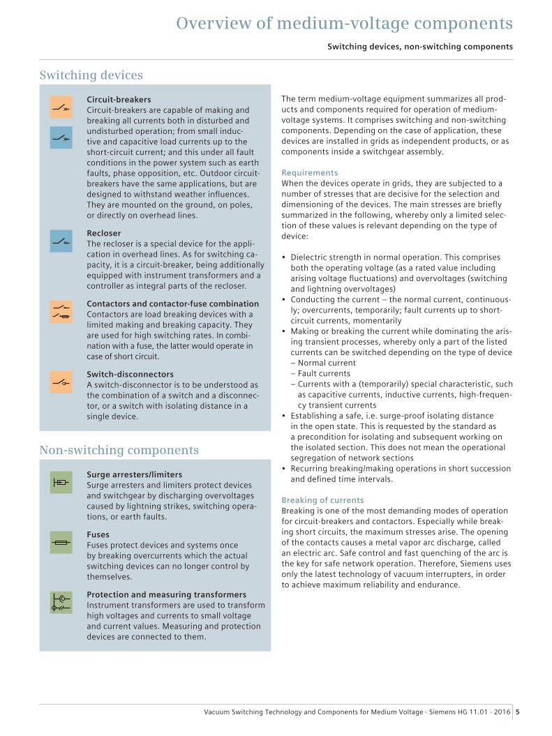
Switching devices
Circuit-breakers Circuit-breakers are capable of making and breaking all currents both in disturbed and undisturbed operation; from small induc-tive and capacitive load currents up to the short-circuit current; and this under all fault conditions in the power system such as earth faults, phase opposition, etc. Outdoor circuit-breakers have the same applications, but are designed to withstand weather influences. They are mounted on the ground, on poles, or directly on overhead lines.
Recloser The recloser is a special device for the appli-cation in overhead lines. As for switching ca-pacity, it is a circuit-breaker, being additionally equipped with instrument transformers and a controller as integral parts of the recloser.
Contactors and contactor-fuse combination Contactors are load breaking devices with a limited making and breaking capacity. They are used for high switching rates. In combi-nation with a fuse, the latter would operate in case of short circuit.
Switch-disconnectors A switch-disconnector is to be understood as the combination of a switch and a disconnec-tor, or a switch with isolating distance in a single device.
Non-switching components
Surge arresters/limiters Surge arresters and limiters protect devices and switchgear by discharging overvoltages caused by lightning strikes, switching opera-tions, or earth faults.
Fuses Fuses protect devices and systems once by breaking overcurrents which the actual switching devices can no longer control by themselves.
Protection and measuring transformers Instrument transformers are used to transform high voltages and currents to small voltage and current values. Measuring and protection devices are connected to them.
6 Vacuum Switching Technology and Components for Medium Voltage · Siemens HG 11.01 · 2016
Vacuum interrupter technology in detail
Overview of medium-voltage components
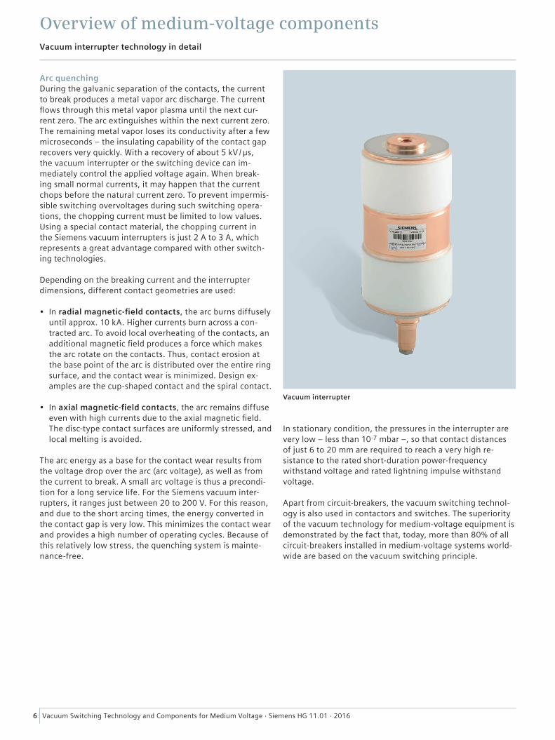
Vacuum interrupter
Arc quenchingDuring the galvanic separation of the contacts, the current to break produces a metal vapor arc discharge. The current flows through this metal vapor plasma until the next cur-rent zero. The arc extinguishes within the next current zero. The remaining metal vapor loses its conductivity after a few microseconds – the insulating capability of the contact gap recovers very quickly. With a recovery of about 5 kV / µs, the vacuum interrupter or the switching device can im-mediately control the applied voltage again. When break-ing small normal currents, it may happen that the current chops before the natural current zero. To prevent impermis-sible switching overvoltages during such switching opera-tions, the chopping current must be limited to low values. Using a special contact material, the chopping current in the Siemens vacuum interrupters is just 2 A to 3 A, which represents a great advantage compared with other switch-ing technologies.
Depending on the breaking current and the interrupter dimensions, different contact geometries are used:
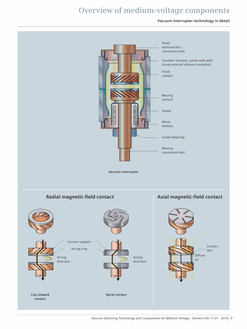
• In radial magnetic-field contacts, the arc burns diffusely until approx. 10 kA. Higher currents burn across a con-tracted arc. To avoid local overheating of the contacts, an additional magnetic field produces a force which makes the arc rotate on the contacts. Thus, contact erosion at the base point of the arc is distributed over the entire ring surface, and the contact wear is minimized. Design ex-amples are the cup-shaped contact and the spiral contact.
• In axial magnetic-field contacts, the arc remains diffuse even with high currents due to the axial magnetic field. The disc-type contact surfaces are uniformly stressed, and local melting is avoided.
The arc energy as a base for the contact wear results from the voltage drop over the arc (arc voltage), as well as from the current to break. A small arc voltage is thus a precondi-tion for a long service life. For the Siemens vacuum inter-rupters, it ranges just between 20 to 200 V. For this reason, and due to the short arcing times, the energy converted in the contact gap is very low. This minimizes the contact wear and provides a high number of operating cycles. Because of this relatively low stress, the quenching system is mainte-nance-free.
In stationary condition, the pressures in the interrupter are very low – less than 10-7 mbar –, so that contact distances of just 6 to 20 mm are required to reach a very high re-sistance to the rated short-duration power-frequency withstand voltage and rated lightning impulse withstand voltage.
Apart from circuit-breakers, the vacuum switching technol-ogy is also used in contactors and switches. The superiority of the vacuum technology for medium-voltage equipment is demonstrated by the fact that, today, more than 80% of all circuit-breakers installed in medium-voltage systems world-wide are based on the vacuum switching principle.
7Vacuum Switching Technology and Components for Medium Voltage · Siemens HG 11.01 · 2016
Vacuum interrupter technology in detail
Overview of medium-voltage components
Fixed terminal disc / connection bolt
Insulator (ceramic, partly with addi-tional external silicone insulation)
Fixed contact
Moving contact
Shield
Metal bellows
Guide (bearing)
Moving connection bolt
Vacuum interrupter
Contact disc
Diffuse arc
Axial magnetic-field contact
Arcing direction
Arcing direction
Cup-shaped contact
Spiral contact
Contact support
Arcing ring
Radial magnetic-field contact

8 Vacuum Switching Technology and Components for Medium Voltage · Siemens HG 11.01 · 2016
Components
Circ
uit-
brea
kers
Cont
acto
rs
Switc
h-di
scon
nect
ors
Recl
oser
s
Fuse
save
rs
Appearing load
Switching application ① Current ② Particularity ③ Remark
Switching duties in inductive circuits
Transformers unloaded ≤ 0.03 Ir – Also valid for neutral earthing transformers ◼ ◼ ◼ ◼ –loaded ≤ 1.2 Ir – Generally no protective circuit required ◼ ◼ ◼ ◼ –
Furnace transformers ≤ 2 Ir High switching rate Overvoltage protection circuit to be configured individually
◼ – – – –
Earth-fault reactors ≤ 300 A – Surge arresters are common practice ◼ – ◼ ◼ –Compensation reactors ≤ 2000 A Transient recovery voltage with
rate of rise ≤ 6 kV / μsOvervoltage protection circuit to be configured individually
◼ – – – –
Motors in operation ≤ Ir – – ◼ ◼ – – –during start ≤ 7 Ir Breaking up to 7 Ir at
cos φ ≤ 0.3For motors with Ian ≤ 600 A, 3EF surge limiters are suitable as protective circuit. Individually compensated motors need no protective circuit
◼ ◼ – – –
Generators in power plants ≤ Ir Transient recovery voltage with high rate of rise
Overvoltage protection is common practice
◼ – – – –
Static converters ≤ Ir – Overvoltage protection is common practice
◼ – – – –
Small inductive currents 20 A < Ir < 600 A
Virtual current chopping by multiple restrikes
Overvoltage protection circuit is common practice; to be configured individually, if required
◼ ◼ – ◼ –
Switching duties in capacitive circuits
Capacitor banks ≤ 1.4 Ir High recovery voltage – ◼ ◼ ◼ ◼ ◼Filter circuits ≤ 1000 A High recovery voltage – ◼ – – – –Parallel connection of capacitor banks
≤ 20 kA @ 4250 Hz
High amplitude and high rate of rise of the inrush current due to high-frequency transient recovery voltage
> 10 kA: reactor required, up to 10 kA: reactor recommended
◼ – – – –
Unloaded cables ≤ 100 A High recovery voltage – ◼ – ◼ ◼ –Unloaded overhead lines ≤ 10 A High recovery voltage – ◼ – ◼ ◼ ◼Phase-controlled closing ≤ Ir POW switching Single-phase switching devices and
corresponding controller required– – – ◼ –
Switching duties for other cases of operation
Disconnecting – – Isolating distance, segregation of networks – – * – –Multiple reclosing – – – – – – ◼ ◼
① This column defines currents which must be switched on or off in the worst case.② This column defines the respective particularities. If nothing is stated, this switching application represents no problem for the switching devices to be used, and needs
not be especially considered for the selection.③ This columns gives general information about the measures to be observed for the application.
Switching applications with undisturbed operation
Selection of components by switching applicationsSwitching applications
* Disconnectors
9Vacuum Switching Technology and Components for Medium Voltage · Siemens HG 11.01 · 2016
Components
Circ
uit-
brea
kers
Cont
acto
rs
Switc
h-di
scon
nect
ors
Recl
oser
s
Fuse
save
rs
Appearing load
Switching application ① Current ② Particularity ③ Remark
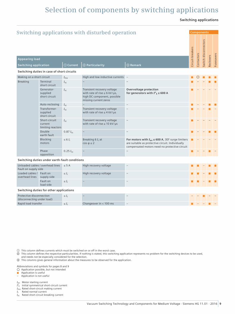
Switching duties in case of short circuits
Making on a short circuit Ima High and low inductive currents – ◼ ⃝ ◼ ◼ ◼Breaking Terminal
short circuitIsc – – ◼ – – ◼ ◼
Generator-supplied short circuit
Isc Transient recovery voltage with rate of rise ≤ 6 kV / μs, high DC component, possible missing current zeros
Overvoltage protection for generators with I“k ≤ 600 A
◼ – – – –
Auto-reclosing Isc – – ◼ – – ◼ ◼Transformer-supplied short circuit
Isc Transient recovery voltage with rate of rise ≤ 4 kV / μs
– ◼ – – ◼ –
Short-circuit current limiting reactors
Isc Transient recovery voltage with rate of rise ≤ 10 kV / μs
– ◼ – – – –
Double earth fault
0.87 Isc – – ◼ – – ◼ ◼
Blocking motors
≤ 6 Ir Breaking 6 Ir at cos φ ≤ 2
For motors with Ian ≤ 600 A, 3EF surge limiters are suitable as protective circuit. Individually compensated motors need no protective circuit
◼ – – – –
Phase opposition
0.25 Isc – – ◼ – – ◼ –
Switching duties under earth-fault conditions
Unloaded cables / overhead lines Fault on supply side
≤ 5 A High recovery voltage – ◼ ◼ – ◼ ◼
Loaded cables / overhead lines
Fault on supply side
≤ Ir High recovery voltage – ◼ ◼ – ◼ ◼
Fault on load side
≤ Ir – – ◼ ◼ – ◼ ◼
Switching duties for other applications
Protective disconnection (disconnecting under load)
≤ Ir – – – – ◼ – –
Rapid load transfer ≤ Ir Changeover in < 100 ms – ◼ – – ◼ –
Switching applications
Selection of components by switching applications
① This column defines currents which must be switched on or off in the worst case.② This column defines the respective particularities. If nothing is stated, this switching application represents no problem for the switching devices to be used,
and needs not be especially considered for the selection.③ This columns gives general information about the measures to be observed for the application.
Abbreviations and symbols for pages 8 and 9 ⃝ Application possible, but not intended ◼ Application is useful– Application is not useful
Ian Motor starting currentI“k Initial symmetrical short-circuit currentIma Rated short-circuit making currentIr Rated normal currentIsc Rated short-circuit breaking current
Switching applications with disturbed operation
10 Vacuum Switching Technology and Components for Medium Voltage · Siemens HG 11.01 · 2016
Stress caused by network operation
Ratings for medium-voltage equipment
Rated voltageThe rated voltage is the upper limit of the highest operating voltage for which the device is designed. It must be equal to or greater than the maximum appearing operating voltage under consideration of the permissible voltage fluctuations. The ratio between the rated voltage and the necessary with-stand voltage values is defined in the product standards.
Rated insulation level or withstand voltageThe rated insulation level is the dielectric strength from phase to earth, between phases and across the open contact gap, or across the isolating distance. The dielectric strength is the capability of an electrical component to withstand overvoltages. These can be operating voltages or higher-frequency voltages caused by switching operations or earth faults (internal overvoltages), as well as lightning strikes (external overvoltages). The dielectric strength is defined by the rated lightning impulse withstand voltage and the rated short-duration power-frequency withstand voltage. Both values are verified by type tests; a power-frequency with-stand voltage test is also an integral part of the routine test.
Rated normal currentThis is the current the device can continuously carry under defined ambient conditions. The dimensioning criterion is the maximum permissible temperature rise of components, which must not exceed the defined temperatures. If a device is mounted in a switchgear, the maximum permissible normal current is determined by the temperature-rise limits when the device is operated in this switchgear.
Rated breaking currentThe rated breaking current defines the breaking capacity of load (normal) currents. For Siemens vacuum switching devices, this value corresponds to the normal current, and is therefore not stated separately.
Rated short-circuit breaking current The rated short-circuit breaking current is the root-mean-square value of the breaking current in case of short circuit. It is stated as a symmetrical current, and corresponds to the short-circuit current after decay of a superimposed DC component.
Rated peak withstand currentThe peak withstand current arises in case of short circuit, and it is the peak value of the first half-wave of the short-circuit current after the beginning of the current flow. It is a measure for the electrodynamic (mechanical) load of an electrical component. This value is highly dependent on the time when the short circuit occurs and on the connected equipment, and it can vary with each switching operation. The rated peak withstand current is the maximum value the device can carry in closed state. The peak withstand current is tested in accordance with the standard, which specifies a fixed ratio between the rated short-circuit breaking current and the rated peak withstand current.
Rated short-circuit making current The rated short-circuit making current is the peak value of the making current in case of short circuit on the load side of the switching device. Its value corresponds to the rated peak withstand current, but it represents a greater stress for the switching device, as dynamic forces work against the closing movement.
Overview of system data
Medium-voltage equipment must be selected for the stresses appearing at the respective place of use. The
ratings of the components describe the maximum values the components can be used for.

11Vacuum Switching Technology and Components for Medium Voltage · Siemens HG 11.01 · 2016
Standards
Ratings for medium-voltage equipment
Overview of standards
All devices are subject to national and international standards. The following table shows the main product standards; superior standards are not included. In addi-
tion, Siemens switching devices are subjected to further tests in order to guarantee safe operation in long years of operation.
International Designation
EN 61869 Instrument transformers
IEC 60099 Surge arresters
IEC 60282-1 High-voltage fuses – Part 1: Current limiting fuses
IEC 60644 Specification for high-voltage fuse-links for motor circuit application
IEC 62271-1 High-voltage switchgear and controlgear – Part 1: Common specifications
IEC 62271-100 High-voltage switchgear and controlgear – Part 100: Alternating current circuit-breakers
IEC 62271-102 High-voltage switchgear and controlgear – Part 102: Alternating current disconnectors and earthing switches
IEC 62271-103 High-voltage switchgear and controlgear – Part 103: Switches for rated voltages above 1 kV up to and including 52 kV
IEC 62271-105 High-voltage switchgear and controlgear – Part 105: Alternating current switch-fuse combinations
IEC 62271-106 High-voltage switchgear and controlgear – Part 106: Alternating current contactors, contactor-based controllers and motor-starters
IEC 62271-111 / IEEE C37.60
High-voltage switchgear and controlgear – Part 111: Automatic circuit reclosers and fault interrupters for alternating current systems up to 38 kV – Reclosers
IEC/IEEE 62271-37-013 High-voltage switchgear and controlgear – Part 37-013: Alternating-current generator circuit-breakers
IEC 62271-200
High-voltage switchgear and controlgear – Part 200: AC metal-enclosed switchgear and controlgear for rated voltages above 1 kV up to and including 52 kV
In many countries, there are local standards that are mostly based on the international standards, but which contain some specific particularities. The main international standards are IEC (Europe) and IEEE (USA). Most of the users in Europe, Asia and Africa request IEC-based standards, while North America follows the IEEE-based standards. As medium-voltage equipment is generally installed in switchgear, or exclusively operated in closed systems, the CE marking is not required.
12 Vacuum Switching Technology and Components for Medium Voltage · Siemens HG 11.01 · 2016
Medium-voltage equipment for indoor applications
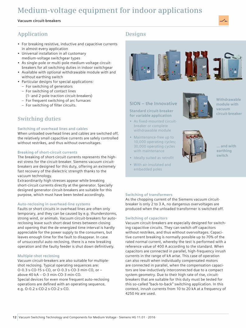
Application
• For breaking resistive, inductive and capacitive currents in almost every application
• Universal installation in all customary medium-voltage switchgear types
• As single-pole or multi-pole medium-voltage circuit-breakers for all switching duties in indoor switchgear
• Available with optional withdrawable module with and without earthing switch
• Particular designs for special applications: – For switching of generators – For switching of contact lines
(1- and 2-pole traction circuit-breakers) – For frequent switching of arc furnaces – For switching of filter circuits.
Switching duties
Switching of overhead lines and cablesWhen unloaded overhead lines and cables are switched off, the relatively small capacitive currents are safely controlled without restrikes, and thus without overvoltages.
Breaking of short-circuit currentsThe breaking of short-circuit currents represents the high-est stress for the circuit-breaker. Siemens vacuum circuit-breakers are designed for this duty, offering an extremely fast recovery of the dielectric strength thanks to the vacuum technology.Extraordinarily high stresses appear while breaking short-circuit currents directly at the generator. Specially designed generator circuit-breakers are suitable for this purpose, which must have been tested accordingly.
Auto-reclosing in overhead-line systemsFaults or short circuits in overhead lines are often only temporary, and they can be caused by e.g. thunderstorms, strong wind, or animals. Vacuum circuit-breakers for auto-reclosing leave such short dead times between closing and opening that the de-energized time interval is hardly appreciable for the power supply to the consumers, but leaves enough time for the fault to disappear. In case of unsuccessful auto-reclosing, there is a new breaking operation and the faulty feeder is shut down definitively.
Multiple-shot reclosingVacuum circuit-breakers are also suitable for multiple- shot reclosing. Typical operating sequences are: O-0.3 s-CO-15 s-CO, or O-0.3 s-CO-3 min-CO, or – above 40 kA – O-3 min-CO-3 min-CO. Special devices for even more frequent auto-reclosing operations are defined with an operating sequence, e.g. O-0.2 s-CO-2 s-CO-2 s-CO.
Designs
Vacuum circuit-breakers
SION – the InnovativeStandard circuit-breaker for variable application• As fixed-mounted circuit-
breaker or complete withdrawable module
• Maintenance-free up to 10,000 operating cycles; 30,000 operating cycles with maintenance
• Ideally suited as retrofit
• With air-insulated and embedded poles
Withdrawable module with vacuum circuit-breaker
... and with earthing switch
Switching of transformersAs the chopping current of the Siemens vacuum circuit-breaker is only 2 to 3 A, no dangerous overvoltages are produced when the unloaded transformer is switched off.
Switching of capacitorsVacuum circuit-breakers are especially designed for switch-ing capacitive circuits. They can switch off capacitors without restrikes, and thus without overvoltages. Capaci-tive current breaking is normally possible up to 70% of the rated normal current, whereby the test is performed with a reference value of 400 A according to the standard. When capacitors are connected in parallel, high-frequency inrush currents in the range of kA arise. This case of operation can also result when individually compensated motors are connected in parallel, when the compensation capaci-tors are low-inductively interconnected due to a compact system geometry. Due to their high rate of rise, circuit-breakers that are suitable for this duty must be tested for this so-called "back-to-back" switching application. In this context, inrush currents from 10 to 20 kA at a frequency of 4250 Hz are used.
13Vacuum Switching Technology and Components for Medium Voltage · Siemens HG 11.01 · 2016
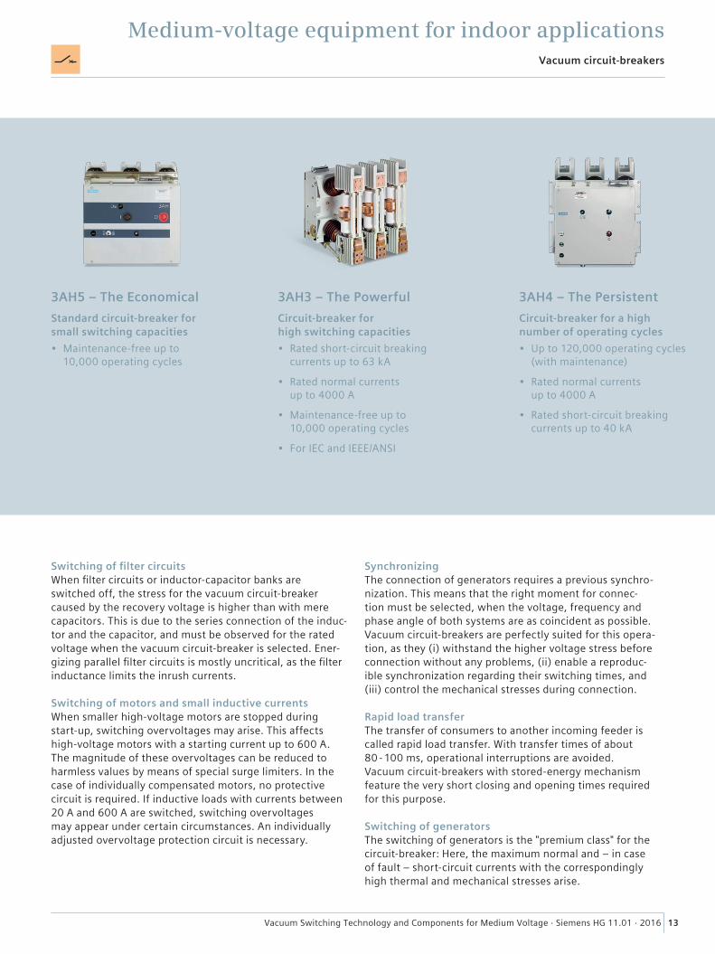
Vacuum circuit-breakers
Medium-voltage equipment for indoor applications
3AH5 – The EconomicalStandard circuit-breaker for small switching capacities• Maintenance-free up to
10,000 operating cycles
3AH3 – The PowerfulCircuit-breaker for high switching capacities• Rated short-circuit breaking
currents up to 63 kA
• Rated normal currents up to 4000 A
• Maintenance-free up to 10,000 operating cycles
• For IEC and IEEE/ANSI
3AH4 – The PersistentCircuit-breaker for a high number of operating cycles• Up to 120,000 operating cycles
(with maintenance)
• Rated normal currents up to 4000 A
• Rated short-circuit breaking currents up to 40 kA
Switching of filter circuitsWhen filter circuits or inductor-capacitor banks are switched off, the stress for the vacuum circuit-breaker caused by the recovery voltage is higher than with mere capacitors. This is due to the series connection of the induc-tor and the capacitor, and must be observed for the rated voltage when the vacuum circuit-breaker is selected. Ener-gizing parallel filter circuits is mostly uncritical, as the filter inductance limits the inrush currents.
Switching of motors and small inductive currentsWhen smaller high-voltage motors are stopped during start-up, switching overvoltages may arise. This affects high-voltage motors with a starting current up to 600 A. The magnitude of these overvoltages can be reduced to harmless values by means of special surge limiters. In the case of individually compensated motors, no protective circuit is required. If inductive loads with currents between 20 A and 600 A are switched, switching overvoltages may appear under certain circumstances. An individually adjusted overvoltage protection circuit is necessary.
SynchronizingThe connection of generators requires a previous synchro-nization. This means that the right moment for connec-tion must be selected, when the voltage, frequency and phase angle of both systems are as coincident as possible. Vacuum circuit-breakers are perfectly suited for this opera-tion, as they (i) withstand the higher voltage stress before connection without any problems, (ii) enable a reproduc-ible synchronization regarding their switching times, and (iii) control the mechanical stresses during connection.
Rapid load transferThe transfer of consumers to another incoming feeder is called rapid load transfer. With transfer times of about 80 - 100 ms, operational interruptions are avoided. Vacuum circuit-breakers with stored-energy mechanism feature the very short closing and opening times required for this purpose.
Switching of generatorsThe switching of generators is the "premium class" for the circuit-breaker: Here, the maximum normal and – in case of fault – short-circuit currents with the correspondingly high thermal and mechanical stresses arise.

14 Vacuum Switching Technology and Components for Medium Voltage · Siemens HG 11.01 · 2016
Vacuum circuit-breakers
Medium-voltage equipment for indoor applications
3AH36, 37, 38 – The StrongCircuit-breakers for high-current and generator applications• Rated normal currents
up to 8000 A
• Maintenance-free up to 10,000 operating cycles
• According to IEC/IEEE 62271-37-013
• Rated short-circuit breaking currents up to 72 kA
• Design for phase segregation up to 24 kV, 100 kA, 12,000 A
3AH47 – The SpecialCircuit-breakers for applications in traction systems• Developed for different system
frequencies, 16 2/3, 25 Hz, 50 or 60 Hz
• 1-pole or 2-pole
• Up to 60,000 operating cycles
3AK7 – The Powerful in Compact DesignCircuit-breaker for industrial applications and generators• Maintenance-free up to
10,000 operating cycles
• For IEC and IEC/IEEE 62271-37-013
Switching of generators (cont.)For this, Siemens consistently relies on vacuum technol-ogy. Thus, applications with high ratings are possible. Gen-erator circuit-breakers from Siemens are generally tested according to the IEC 62271-100 and IEC/IEEE 62271-37-013 standards, which are considered the leading standard for generator circuit-breakers.
Switching of arc furnacesWhile circuit-breakers for standard applications are only rarely switched during the year, arc furnaces require up to 100 operating cycles a day. The 3AH4 vacuum circuit-break-er is especially adequate for this purpose. In this application, the load currents can be asymmetrical and distorted. To avoid resonance oscillations in the furnace transformers, individually adjusted protective circuits are necessary.
Auto-reclosing in traction line systemsTo check the traction line system via test resistors for absence of short circuits after a short-circuit shutdown, the operating sequence is O-15 s-CO.
Type of operating mechanism
Circuit-breakers are almost exclusively equipped with stored-energy mechanisms, either as stored-energy spring mechanisms or as magnetic actuators:
• Stored-energy spring mechanism – Mechanical energy stored in a spring – For a normal number of operating cycles and
frequent-operation applications – Suitable for all applications throughout the
complete range of ratings – For long years without maintenance thanks to
exclusively mechanical components• Magnetic actuator
– Mechanical energy stored in a capacitor – For a normal number of operating cycles up to
extremely frequent applications – For applications with small and medium-sized
short-circuit currents – Maintenance-free mechanical components and
maintenance schedule for the electronic control.
15Vacuum Switching Technology and Components for Medium Voltage · Siemens HG 11.01 · 2016
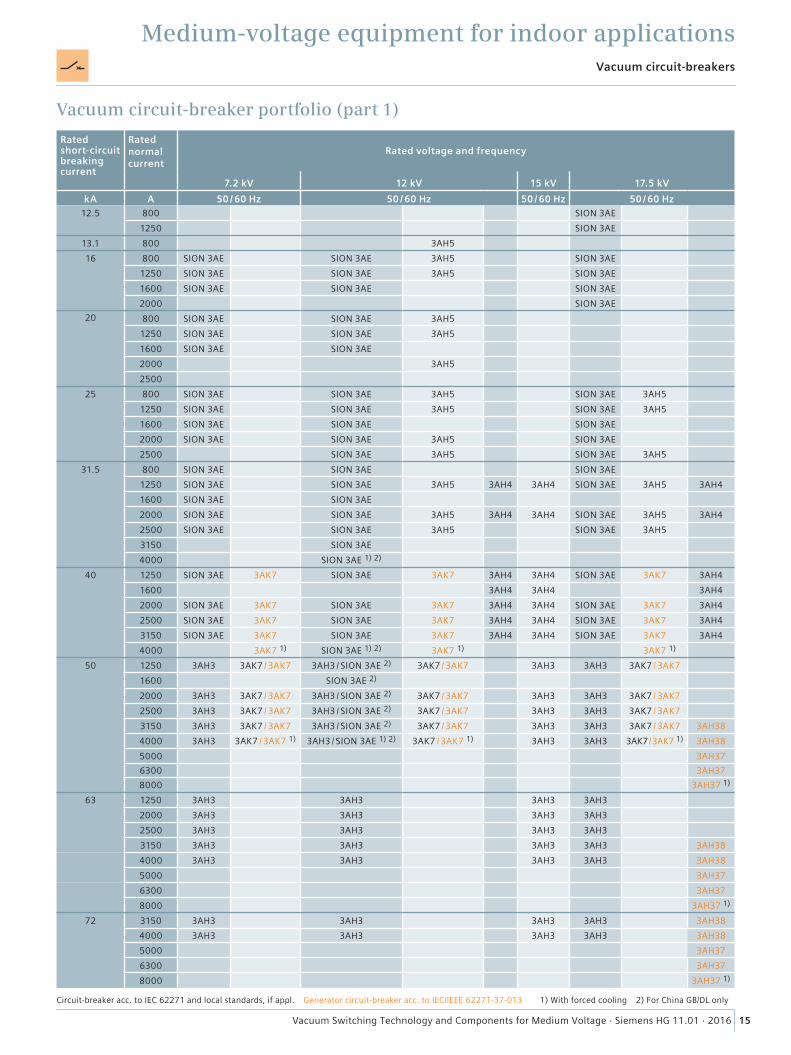
Medium-voltage equipment for indoor applicationsVacuum circuit-breakers
Rated short-circuit breaking current
Rated normal current
Rated voltage and frequency
7.2 kV 12 kV 15 kV 17.5 kVkA A 50 / 60 Hz 50 / 60 Hz 50 / 60 Hz 50 / 60 Hz
12.5 800 SION 3AE1250 SION 3AE
13.1 800 3AH516 800 SION 3AE SION 3AE 3AH5 SION 3AE
1250 SION 3AE SION 3AE 3AH5 SION 3AE1600 SION 3AE SION 3AE SION 3AE2000 SION 3AE
20 800 SION 3AE SION 3AE 3AH51250 SION 3AE SION 3AE 3AH51600 SION 3AE SION 3AE2000 3AH52500
25 800 SION 3AE SION 3AE 3AH5 SION 3AE 3AH51250 SION 3AE SION 3AE 3AH5 SION 3AE 3AH51600 SION 3AE SION 3AE SION 3AE2000 SION 3AE SION 3AE 3AH5 SION 3AE2500 SION 3AE 3AH5 SION 3AE 3AH5
31.5 800 SION 3AE SION 3AE SION 3AE1250 SION 3AE SION 3AE 3AH5 3AH4 3AH4 SION 3AE 3AH5 3AH41600 SION 3AE SION 3AE2000 SION 3AE SION 3AE 3AH5 3AH4 3AH4 SION 3AE 3AH5 3AH42500 SION 3AE SION 3AE 3AH5 SION 3AE 3AH53150 SION 3AE4000 SION 3AE 1) 2)
40 1250 SION 3AE 3AK7 SION 3AE 3AK7 3AH4 3AH4 SION 3AE 3AK7 3AH41600 3AH4 3AH4 3AH42000 SION 3AE 3AK7 SION 3AE 3AK7 3AH4 3AH4 SION 3AE 3AK7 3AH42500 SION 3AE 3AK7 SION 3AE 3AK7 3AH4 3AH4 SION 3AE 3AK7 3AH43150 SION 3AE 3AK7 SION 3AE 3AK7 3AH4 3AH4 SION 3AE 3AK7 3AH44000 3AK7 1) SION 3AE 1) 2) 3AK7 1) 3AK7 1)
50 1250 3AH3 3AK7 / 3AK7 3AH3 / SION 3AE 2) 3AK7 / 3AK7 3AH3 3AH3 3AK7 / 3AK71600 SION 3AE 2)
2000 3AH3 3AK7 / 3AK7 3AH3 / SION 3AE 2) 3AK7 / 3AK7 3AH3 3AH3 3AK7 / 3AK72500 3AH3 3AK7 / 3AK7 3AH3 / SION 3AE 2) 3AK7 / 3AK7 3AH3 3AH3 3AK7 / 3AK73150 3AH3 3AK7 / 3AK7 3AH3 / SION 3AE 2) 3AK7 / 3AK7 3AH3 3AH3 3AK7 / 3AK7 3AH384000 3AH3 3AK7 / 3AK7 1) 3AH3 / SION 3AE 1) 2) 3AK7 / 3AK7 1) 3AH3 3AH3 3AK7 / 3AK7 1) 3AH385000 3AH376300 3AH378000 3AH37 1)
63 1250 3AH3 3AH3 3AH3 3AH32000 3AH3 3AH3 3AH3 3AH32500 3AH3 3AH3 3AH3 3AH33150 3AH3 3AH3 3AH3 3AH3 3AH384000 3AH3 3AH3 3AH3 3AH3 3AH385000 3AH376300 3AH378000 3AH37 1)
72 3150 3AH3 3AH3 3AH3 3AH3 3AH384000 3AH3 3AH3 3AH3 3AH3 3AH385000 3AH376300 3AH378000 3AH37 1)
Vacuum circuit-breaker portfolio (part 1)
Circuit-breaker acc. to IEC 62271 and local standards, if appl. Generator circuit-breaker acc. to IEC/IEEE 62271-37-013 1) With forced cooling 2) For China GB/DL only
16 Vacuum Switching Technology and Components for Medium Voltage · Siemens HG 11.01 · 2016
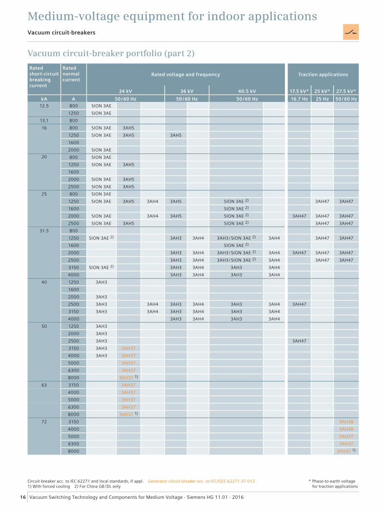
Rated short-circuit breaking current
Rated normal current
Rated voltage and frequency
24 kV 36 kV 40.5 kVkA A 50 / 60 Hz 50 / 60 Hz 50 / 60 Hz
12.5 800 SION 3AE1250 SION 3AE
13.1 80016 800 SION 3AE 3AH5
1250 SION 3AE 3AH5 3AH516002000 SION 3AE
20 800 SION 3AE1250 SION 3AE 3AH516002000 SION 3AE 3AH52500 SION 3AE 3AH5
25 800 SION 3AE1250 SION 3AE 3AH5 3AH4 3AH5 SION 3AE 2)
1600 SION 3AE 2)
2000 SION 3AE 3AH4 3AH5 SION 3AE 2)
2500 SION 3AE 3AH5 SION 3AE 2)
31.5 8001250 SION 3AE 2) 3AH3 3AH4 3AH3 / SION 3AE 2) 3AH41600 SION 3AE 2)
2000 3AH3 3AH4 3AH3 / SION 3AE 2) 3AH42500 3AH3 3AH4 3AH3 / SION 3AE 2) 3AH43150 SION 3AE 2) 3AH3 3AH4 3AH3 3AH44000 3AH3 3AH4 3AH3 3AH4
40 1250 3AH316002000 3AH32500 3AH3 3AH4 3AH3 3AH4 3AH3 3AH43150 3AH3 3AH4 3AH3 3AH4 3AH3 3AH44000 3AH3 3AH4 3AH3 3AH4
50 1250 3AH32000 3AH32500 3AH33150 3AH3 3AH374000 3AH3 3AH375000 3AH376300 3AH378000 3AH37 1)
63 3150 3AH374000 3AH375000 3AH376300 3AH378000 3AH37 1)
72 31504000500063008000
Traction applications
17.5 kV* 25 kV* 27.5 kV*16.7 Hz 25 Hz 50 / 60 Hz
3AH47 3AH47
3AH47 3AH47 3AH473AH47 3AH47
3AH47 3AH47
3AH47 3AH47 3AH473AH47 3AH47
3AH47
3AH47
3AH383AH383AH373AH37
3AH37 1)
Vacuum circuit-breakers
Medium-voltage equipment for indoor applications
Vacuum circuit-breaker portfolio (part 2)
Circuit-breaker acc. to IEC 62271 and local standards, if appl. Generator circuit-breaker acc. to IEC/IEEE 62271-37-013 1) With forced cooling 2) For China GB / DL only
* Phase-to-earth voltage for traction applications
17Vacuum Switching Technology and Components for Medium Voltage · Siemens HG 11.01 · 2016
����
����
����
����
�
��
��
����� ����� � ��� ����� ����� ������������������
�� ���� �� ��
�� � �� �� ��
�� ���� �� ��
�� ���� �� ��
�� ���� �� ��
���� ��� ��������
������������
������� ������
������������
��������������
��������������
� �����������
��������
�������
�� ����
�������
������
�������� ������� ������
��������� ����� �� ��� ��� ��� ����������������������������������������
���������������� �������� ���������������
������������������
��������������������������������������������������������������������������������������������
Medium-voltage equipment for indoor applicationsVacuum circuit-breakers
Application
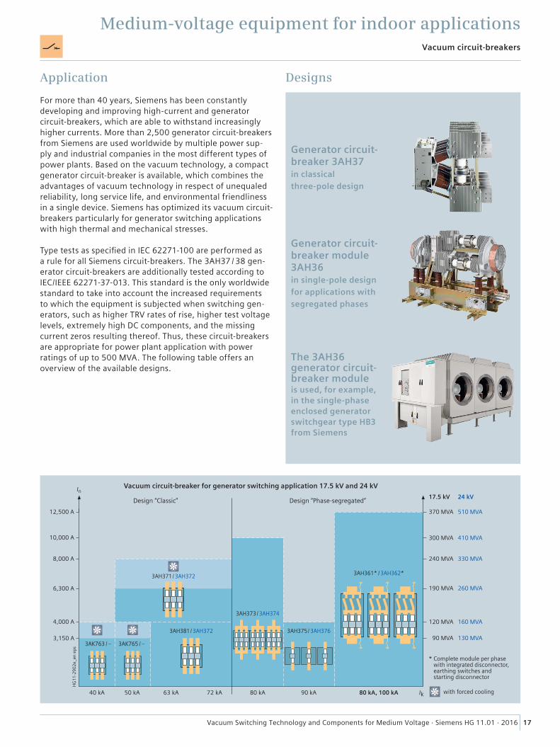
For more than 40 years, Siemens has been constantly developing and improving high-current and generator circuit-breakers, which are able to withstand increasingly higher currents. More than 2,500 generator circuit-breakers from Siemens are used worldwide by multiple power sup-ply and industrial companies in the most different types of power plants. Based on the vacuum technology, a compact generator circuit-breaker is available, which combines the advantages of vacuum technology in respect of unequaled reliability, long service life, and environmental friendliness in a single device. Siemens has optimized its vacuum circuit-breakers particularly for generator switching applications with high thermal and mechanical stresses.
Type tests as specified in IEC 62271-100 are performed as a rule for all Siemens circuit-breakers. The 3AH37 / 38 gen-erator circuit-breakers are additionally tested according to IEC/IEEE 62271-37-013. This standard is the only worldwide standard to take into account the increased requirements to which the equipment is subjected when switching gen-erators, such as higher TRV rates of rise, higher test voltage levels, extremely high DC components, and the missing current zeros resulting thereof. Thus, these circuit-breakers are appropriate for power plant application with power ratings of up to 500 MVA. The following table offers an overview of the available designs.
Designs
Generator circuit-breaker module 3AH36 in single-pole design for applications with segregated phases
Generator circuit-breaker 3AH37 in classical three-pole design
The 3AH36 generator circuit-breaker module is used, for example, in the single-phase enclosed generator switchgear type HB3 from Siemens
18 Vacuum Switching Technology and Components for Medium Voltage · Siemens HG 11.01 · 2016
Medium-voltage equipment for indoor applications
Application
Switch-disconnectors combine the functions of a switch with those of a disconnector, and are therefore used for breaking load currents up to their rated normal current. While connecting consumers, making on an existing short-circuit cannot be excluded. That is why, today, switch-dis-connectors generally feature a short-circuit making capacity. In combination with fuses, switches (switch-disconnectors) can also be used to break short-circuit currents. The short-circuit current is interrupted by the fuses. Subsequently, the fuses trip the three poles of the switch(-disconnector), disconnecting the faulty feeder from the power system.
Quenching principle
In switch-disconnectors, the arc is not extinguished in a vacuum interrupter, but they operate according to the principle of a hard-gas switch. This means that the arc splits off some gas from an insulating material which surrounds the arc closely, and this gas quenches the arc fast and ef-fectively. As the material providing the gas cannot regener-ate itself, the number of operating cycles is lower than that of applications with vacuum interrupters. Nevertheless, switch-disconnectors according to the hard-gas principle are the most frequently used ones, as they have a good cost/performance ratio.
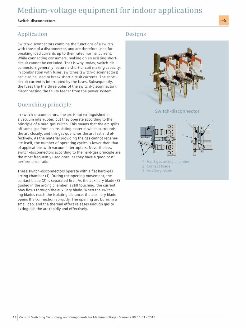
These switch-disconnectors operate with a flat hard-gas arcing chamber (1). During the opening movement, the contact blade (2) is separated first. As the auxiliary blade (3) guided in the arcing chamber is still touching, the current now flows through the auxiliary blade. When the switch-ing blades reach the isolating distance, the auxiliary blade opens the connection abruptly. The opening arc burns in a small gap, and the thermal effect releases enough gas to extinguish the arc rapidly and effectively.
Designs
Switch-disconnector
1 1
2
3
3
1 Hard-gas arcing chamber2 Contact blade3 Auxiliary blade
Switch-disconnectors
19Vacuum Switching Technology and Components for Medium Voltage · Siemens HG 11.01 · 2016
Medium-voltage equipment for indoor applicationsVacuum contactors, contactor-fuse combination
Application
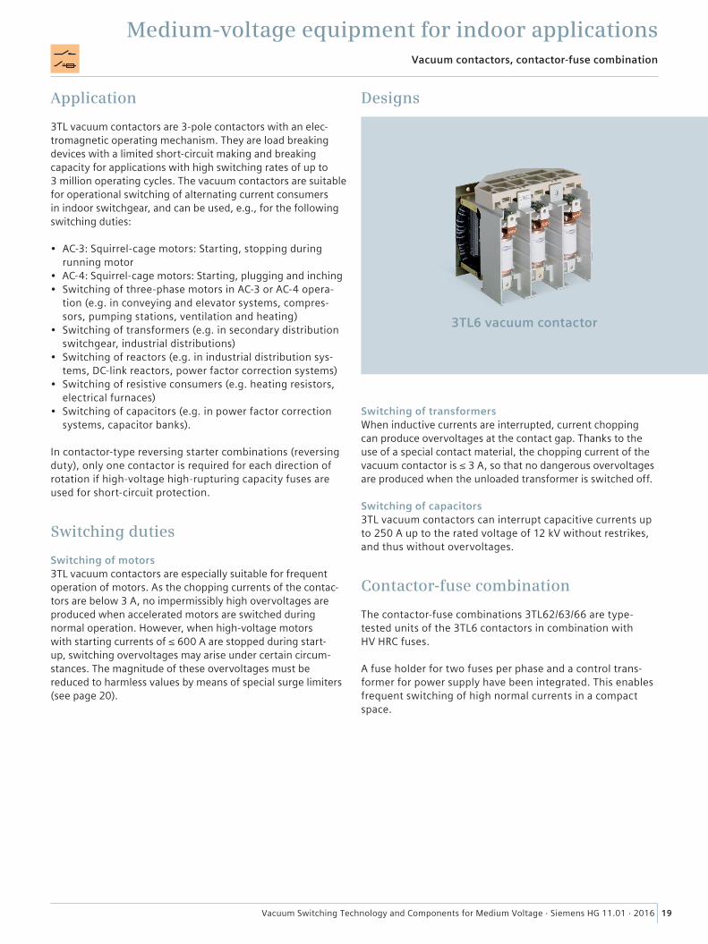
3TL vacuum contactors are 3-pole contactors with an elec-tromagnetic operating mechanism. They are load breaking devices with a limited short-circuit making and breaking capacity for applications with high switching rates of up to 3 million operating cycles. The vacuum contactors are suitable for operational switching of alternating current consumers in indoor switchgear, and can be used, e.g., for the following switching duties:
• AC-3: Squirrel-cage motors: Starting, stopping during running motor
• AC-4: Squirrel-cage motors: Starting, plugging and inching• Switching of three-phase motors in AC-3 or AC-4 opera-
tion (e.g. in conveying and elevator systems, compres-sors, pumping stations, ventilation and heating)
• Switching of transformers (e.g. in secondary distribution switchgear, industrial distributions)
• Switching of reactors (e.g. in industrial distribution sys-tems, DC-link reactors, power factor correction systems)
• Switching of resistive consumers (e.g. heating resistors, electrical furnaces)
• Switching of capacitors (e.g. in power factor correction systems, capacitor banks).
In contactor-type reversing starter combinations (reversing duty), only one contactor is required for each direction of rotation if high-voltage high-rupturing capacity fuses are used for short-circuit protection.
Switching duties
Switching of motors3TL vacuum contactors are especially suitable for frequent operation of motors. As the chopping currents of the contac-tors are below 3 A, no impermissibly high overvoltages are produced when accelerated motors are switched during normal operation. However, when high-voltage motors with starting currents of ≤ 600 A are stopped during start-up, switching overvoltages may arise under certain circum-stances. The magnitude of these overvoltages must be reduced to harmless values by means of special surge limiters (see page 20).
Designs
3TL6 vacuum contactor
Switching of transformersWhen inductive currents are interrupted, current chopping can produce overvoltages at the contact gap. Thanks to the use of a special contact material, the chopping current of the vacuum contactor is ≤ 3 A, so that no dangerous overvoltages are produced when the unloaded transformer is switched off.
Switching of capacitors3TL vacuum contactors can interrupt capacitive currents up to 250 A up to the rated voltage of 12 kV without restrikes, and thus without overvoltages.
Contactor-fuse combination
The contactor-fuse combinations 3TL62/63/66 are type- tested units of the 3TL6 contactors in combination with HV HRC fuses.
A fuse holder for two fuses per phase and a control trans-former for power supply have been integrated. This enables frequent switching of high normal currents in a compact space.
20 Vacuum Switching Technology and Components for Medium Voltage · Siemens HG 11.01 · 2016
Medium-voltage equipment for indoor applicationsVacuum contactors, contactor-fuse combination
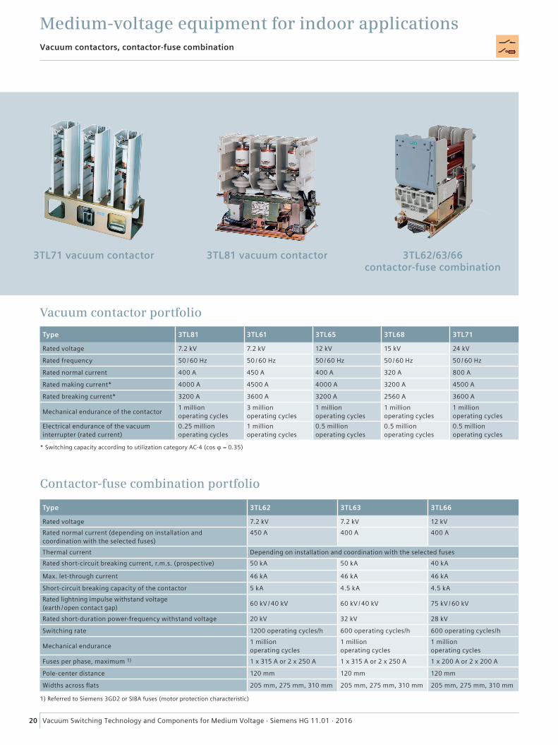
3TL81 vacuum contactor 3TL62/63/66 contactor-fuse combination
3TL71 vacuum contactor
Vacuum contactor portfolio
Type 3TL81 3TL61 3TL65 3TL68 3TL71
Rated voltage 7.2 kV 7.2 kV 12 kV 15 kV 24 kV
Rated frequency 50 / 60 Hz 50 / 60 Hz 50 / 60 Hz 50 / 60 Hz 50 / 60 Hz
Rated normal current 400 A 450 A 400 A 320 A 800 A
Rated making current* 4000 A 4500 A 4000 A 3200 A 4500 A
Rated breaking current* 3200 A 3600 A 3200 A 2560 A 3600 A
Mechanical endurance of the contactor 1 million operating cycles
3 million operating cycles
1 million operating cycles
1 million operating cycles
1 million operating cycles
Electrical endurance of the vacuum interrupter (rated current)
0.25 million operating cycles
1 million operating cycles
0.5 million operating cycles
0.5 million operating cycles
0.5 million operating cycles
* Switching capacity according to utilization category AC-4 (cos φ = 0.35)
Contactor-fuse combination portfolio
Type 3TL62 3TL63 3TL66
Rated voltage 7.2 kV 7.2 kV 12 kVRated normal current (depending on installation and coordination with the selected fuses)
450 A 400 A 400 A
Thermal current Depending on installation and coordination with the selected fusesRated short-circuit breaking current, r.m.s. (prospective) 50 kA 50 kA 40 kA
Max. let-through current 46 kA 46 kA 46 kA
Short-circuit breaking capacity of the contactor 5 kA 4.5 kA 4.5 kARated lightning impulse withstand voltage (earth / open contact gap) 60 kV / 40 kV 60 kV / 40 kV 75 kV / 60 kV
Rated short-duration power-frequency withstand voltage 20 kV 32 kV 28 kV
Switching rate 1200 operating cycles/h 600 operating cycles/h 600 operating cycles/h
Mechanical endurance 1 million operating cycles
1 million operating cycles
1 million operating cycles
Fuses per phase, maximum 1) 1 x 315 A or 2 x 250 A 1 x 315 A or 2 x 250 A 1 x 200 A or 2 x 200 A
Pole-center distance 120 mm 120 mm 120 mm
Widths across flats 205 mm, 275 mm, 310 mm 205 mm, 275 mm, 310 mm 205 mm, 275 mm, 310 mm
1) Referred to Siemens 3GD2 or SIBA fuses (motor protection characteristic)
21Vacuum Switching Technology and Components for Medium Voltage · Siemens HG 11.01 · 2016
Partnering
Medium-voltage equipment for indoor applications
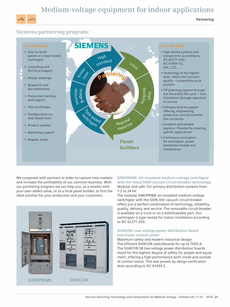
We cooperate with partners in order to capture new markets and increase the profitability of our common business. With our partnering program we can help you, as a reseller with your own added value, or as a local panel builder, to find the ideal solution for your production and your customers.
Siemens partnering program:
SIMOPRIME: Air-insulated medium-voltage switchgear with the latest SION vacuum circuit-breaker technologyModular and safe: For primary distribution systems from 7.2 to 24 kV. The modular SIMOPRIME air-insulated medium-voltage switchgear with the SION 3AE vacuum circuit-breaker offers you a perfect combination of technology, reliability, quality, delivery and service. The removable circuit-breaker is available on a truck or on a withdrawable part. Our switchgear is type-tested for indoor installation according to IEC 62271-200.
SIVACON: Low-voltage power distribution board and motor control centerMaximum safety and modern industrial design: The efficient SIVACON switchboards for up to 7000 A. The SIVACON S8 low-voltage power distribution boards stand for the highest degree of safety for people and equip-ment, offering a high performance both inside and outside of control rooms. This was proven by design verification tests according to IEC 61439-2.
SIMOPRIME SIVACON
Panel builders
Your benefits:
• Type-tested systems and components according to IEC 62271-200 / IEC 61439-1/2, EAC, CCC, …
• Technology at the highest level, safety and constant quality – competitive price position
• TIP planning support through-out the entire life cycle – from installation through operation to service
• Software tools to support offering, engineering, production and documenta-tion processes
• Excellent and reliable logistics / flexible for ordering specific applications
• Continuous innovation for switchgear, power distribution boards and components
Our offerings:
• Easy-to-build panels of a type-tested switchgear
• Consulting and technical support
• Design drawings
• Blueprints and documentation
• Production training and support
• Test certificates
• Configuration via web-based tools
• Product updates
• Marketing support
• Regular audits
High
Regional
Type-tested
Local
High
standard
f exibility
Image &
resources
switchgear
expertise
how
Know
-
22 Vacuum Switching Technology and Components for Medium Voltage · Siemens HG 11.01 · 2016
Medium-voltage equipment for outdoor applicationsOutdoor vacuum circuit-breakers
Application
Outdoor vacuum circuit-breakers are especially designed for outdoor installation. The design is based on the proven 3AH operating mechanism and a simple structure, in order to guarantee a long electrical and mechanical endurance, offering all advantages of indoor vacuum circuit-breakers at the same time.
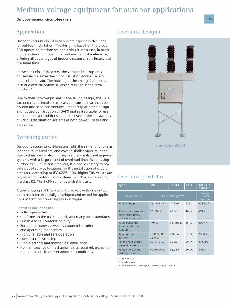
In live-tank circuit-breakers, the vacuum interrupter is housed inside a weatherproof insulating enclosure, e.g. made of porcelain. The housing of the arcing chamber is thus at electrical potential, which resulted in the term "live tank".
Due to their low-weight and space-saving design, the 3AF0 vacuum circuit-breakers are easy to transport, and can be divided into separate modules. The safety-oriented design and rugged construction of 3AF0 makes it suitable for use in the harshest conditions. It can be used in the substations of various distribution systems of both power utilities and industries.
Switching duties
Outdoor vacuum circuit-breakers fulfil the same functions as indoor circuit-breakers, and cover a similar product range. Due to their special design they are preferably used in power systems with a large extent of overhead lines. When using outdoor vacuum circuit-breakers, it is not necessary to pro-vide closed service locations for the installation of circuit-breakers. According to IEC 62271-100, higher TRV values are requested for outdoor applications, which is expressed by the class S2. The 3AF0 complies with this class.
A special design of these circuit-breakers with one or two poles has been especially developed and tested for applica-tions in traction power supply switchgear.
Features and benefits• Fully type-tested • Conforms to the IEC standards and many local standards• Suitable for auto-reclosing duty• Perfect harmony between vacuum interrupter
and operating mechanism• Highly reliable and safe operation• Low cost of ownership• High electrical and mechanical endurance• No maintenance of mechanical parts required, except for
regular checks in case of abnormal conditions.
Live-tank designs
Live-tank portfolio
Live tank 3AF0
Type 3AF01 3AF03 3AF09
Application in distribution systems
Rated voltage 36 / 40.5 kV 17.5 kV 12 kV
Rated short-duration power-frequency withstand voltage
70 / 95 kV 42 kV 48 kV
Rated lightning impulse withstand voltage
170 kV 95 / 110 kV 85 kV
Rated normal current
1600 / 2000 / 2500 A
2000 A 630 A
Rated short-circuit breaking current
25 / 31.5 kA 25 kA 20 kA
Rated short-circuit making current
62.5 / 80 kA 62.5 kA 50 kA
* Single-pole** Double-pole1) Phase-to-earth voltage for traction applications
3AF04* / 3AF05**
traction power
systems
27.5 kV 1)
95 kV
200 kV
2500 A
31.5 kA
80 kA
23Vacuum Switching Technology and Components for Medium Voltage · Siemens HG 11.01 · 2016
Medium-voltage equipment for outdoor applicationsOutdoor vacuum circuit-breakers
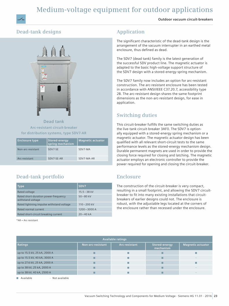
Dead-tank designs
Dead-tank portfolio
Dead tank
Enclosure type Stored-energy spring mechanism
Magnetic actuator
Non-arc-resistant SDV7-SE SDV7-MA
Arc-resistant SDV7-SE-AR SDV7-MA-AR
Arc-resistant circuit-breaker for distribution systems, type SDV7-AR
Type SDV7
Rated voltage 15.5 – 38 kVRated short-duration power-frequency withstand voltage
50 – 80 kV
Rated lightning impulse withstand voltage 110 – 200 kV
Rated normal current 1200 – 3000 A
Rated short-circuit breaking current 20 – 40 kA
Available ratings
Ratings Non-arc-resistant Arc-resistant Stored-energy mechanism
Magnetic actuator
up to 15.5 kV, 25 kA, 2000 A ◼ ◼ ◼ ◼
up to 15.5 kV, 40 kA, 3000 A ◼ ◼ ◼ –
up to 27.6 kV, 25 kA, 2000 A ◼ ◼ ◼ ◼
up to 38 kV, 25 kA, 2000 A ◼ ◼ ◼ –
up to 38 kV, 40 kA, 2500 A ◼ ◼ ◼ –
Application
The significant characteristic of the dead-tank design is the arrangement of the vacuum interrupter in an earthed metal enclosure, thus defined as dead.
The SDV7 (dead tank) family is the latest generation of the successful SDV product line. The magnetic actuator is adapted to the basic high-voltage support structure of the SDV7 design with a stored-energy spring mechanism.
The SDV7 family now includes an option for arc-resistant construction. The arc-resistant enclosure has been tested in accordance with ANSI/IEEE C37.20.7, accessibility type 2B. The arc-resistant design shares the same footprint dimensions as the non-arc-resistant design, for ease in application.
Switching duties
This circuit-breaker fulfills the same switching duties as the live-tank circuit-breaker 3AF0. The SDV7 is option-ally equipped with a stored-energy spring mechanism or a magnetic actuator. The magnetic actuator design has been qualified with all relevant short-circuit tests to the same performance levels as the stored-energy mechanism design. Durable permanent magnets are used in order to provide the closing force required for closing and latching. The magnetic actuator employs an electronic controller to provide the power required for opening and closing the circuit-breaker.
Enclosure
The construction of the circuit-breaker is very compact, resulting in a small footprint, and allowing the SDV7 circuit- breaker to fit into many existing installations that circuit-breakers of earlier designs could not. The enclosure is robust, with the adjustable legs located at the corners of the enclosure rather than recessed under the enclosure.
*AR = Arc-resistant
◼ Available – Not available
24 Vacuum Switching Technology and Components for Medium Voltage · Siemens HG 11.01 · 2016
Medium-voltage equipment for outdoor applicationsRecloser
Application
3AD vacuum reclosers combine the latest technology in vacuum switching and electronic control as well as network protection. They are based on decades of experi-ence in vacuum switching technology and circuit-breaker design, protection relay development and network plan-ning. Siemens reclosers meet all the requirements for outdoor use in accordance with the recloser standards IEC/IEEE 62271-37-013 / IEC 62271-111.
The recloser consists of two main components: The switch unit, similar to a circuit-breaker, and the control-ler as protection and control unit. The latter is located inside the control cubicle, which also contains the electronics and auxiliary circuits.
Switching duties
Recloser principleReclosers are used in overhead lines as well as in substa-tions. Like circuit-breakers they are capable of switching normal and fault currents. Being equipped with sensors and a controller as protection and control unit, they can trip and reclose up to four times in case of a temporary fault, thus avoiding longer network interruptions.
As outdoor devices, reclosers are mounted on a pole or a support in an outdoor substation, and are therefore exposed to environmental and weather conditions. Extensive testing beyond the recloser standard has proven the suitability for such applications to ensure long service life.
Recloser cycleIn case of a network fault, the recloser opens and recloses several times. In case of temporary faults, this multiple-shot automatic reclosing significantly reduces the outage times.
The operating cycles can be set individually for each mode of operation optimizing the recloser to:
• The first two interruptions of a fault are set to instanta-neous protection, so that downstream protection devices (e.g. sectionalizers, fuses) do not operate. If the fault is temporary, supply is restored after one or several reclos-ing operations.
• The subsequent interruptions have a delayed protection setting. Thus, downstream fuses on network laterals have the chance to operate and isolate the affected network section, restoring normal operation in the main feeder.
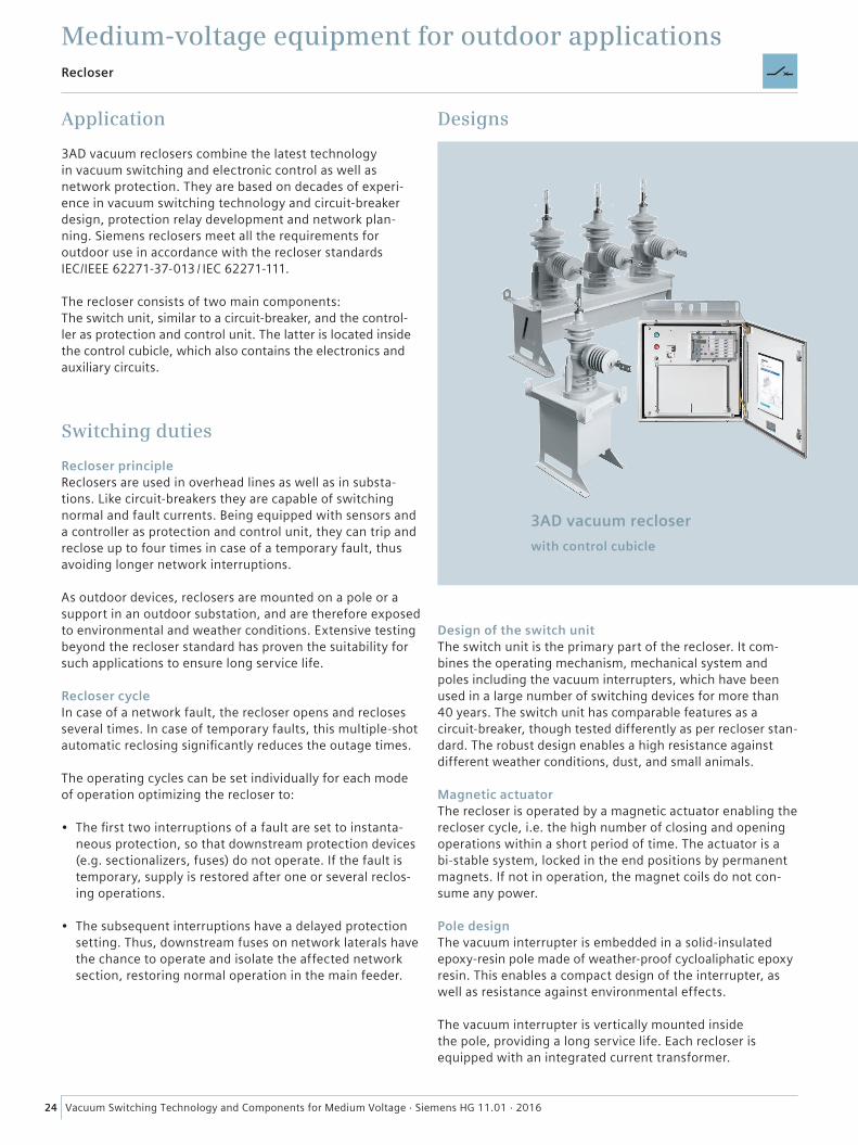
Designs
3AD vacuum recloserwith control cubicle
Design of the switch unitThe switch unit is the primary part of the recloser. It com-bines the operating mechanism, mechanical system and poles including the vacuum interrupters, which have been used in a large number of switching devices for more than 40 years. The switch unit has comparable features as a circuit-breaker, though tested differently as per recloser stan-dard. The robust design enables a high resistance against different weather conditions, dust, and small animals.
Magnetic actuatorThe recloser is operated by a magnetic actuator enabling the recloser cycle, i.e. the high number of closing and opening operations within a short period of time. The actuator is a bi-stable system, locked in the end positions by permanent magnets. If not in operation, the magnet coils do not con-sume any power.
Pole designThe vacuum interrupter is embedded in a solid-insulated epoxy-resin pole made of weather-proof cycloaliphatic epoxy resin. This enables a compact design of the interrupter, as well as resistance against environmental effects.
The vacuum interrupter is vertically mounted inside the pole, providing a long service life. Each recloser is equipped with an integrated current transformer.
25Vacuum Switching Technology and Components for Medium Voltage · Siemens HG 11.01 · 2016
Medium-voltage equipment for outdoor applicationsRecloser
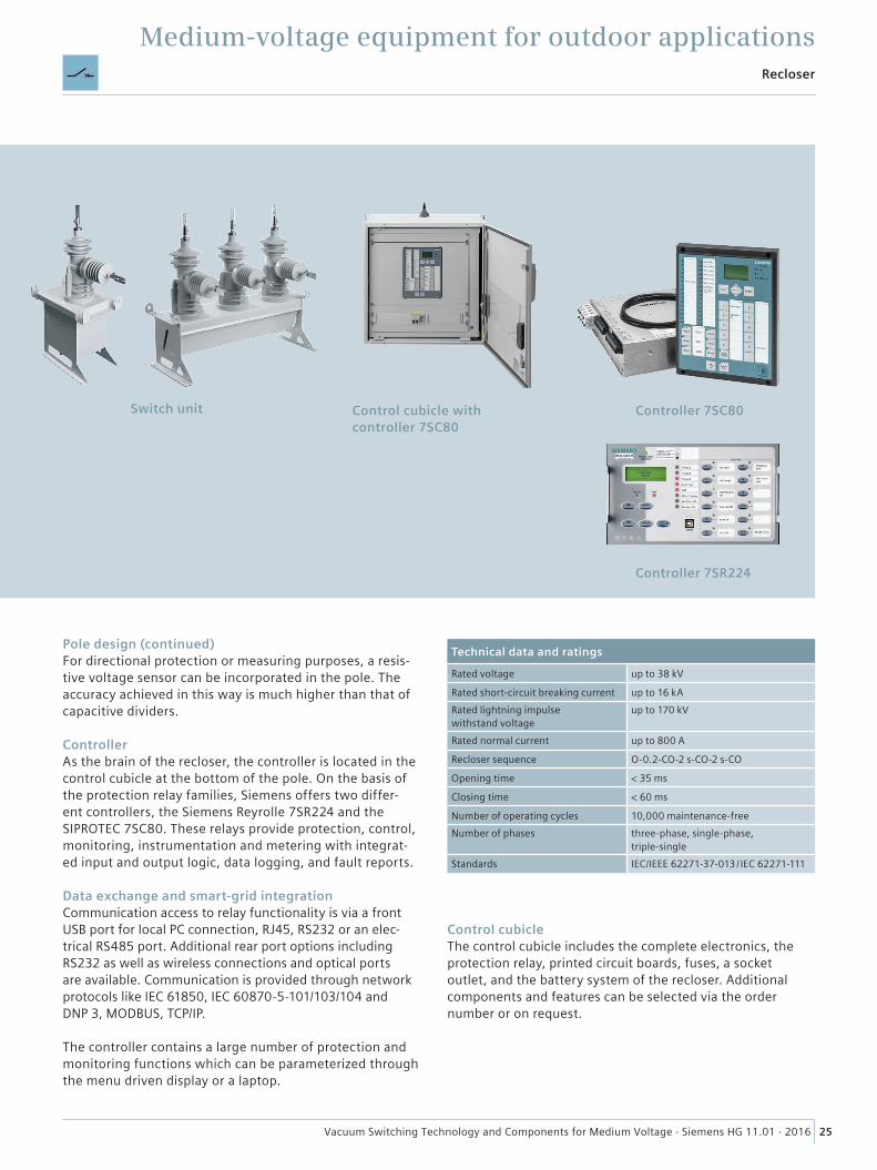
Switch unit
Pole design (continued)For directional protection or measuring purposes, a resis-tive voltage sensor can be incorporated in the pole. The accuracy achieved in this way is much higher than that of capacitive dividers.
ControllerAs the brain of the recloser, the controller is located in the control cubicle at the bottom of the pole. On the basis of the protection relay families, Siemens offers two differ-ent controllers, the Siemens Reyrolle 7SR224 and the SIPROTEC 7SC80. These relays provide protection, control, monitoring, instrumentation and metering with integrat-ed input and output logic, data logging, and fault reports.
Data exchange and smart-grid integrationCommunication access to relay functionality is via a front USB port for local PC connection, RJ45, RS232 or an elec-trical RS485 port. Additional rear port options including RS232 as well as wireless connections and optical ports are available. Communication is provided through network protocols like IEC 61850, IEC 60870-5-101/103/104 and DNP 3, MODBUS, TCP/IP.
The controller contains a large number of protection and monitoring functions which can be parameterized through the menu driven display or a laptop.
Control cubicleThe control cubicle includes the complete electronics, the protection relay, printed circuit boards, fuses, a socket outlet, and the battery system of the recloser. Additional components and features can be selected via the order number or on request.
Control cubicle with controller 7SC80
Controller 7SC80
Controller 7SR224
Technical data and ratings
Rated voltage up to 38 kV
Rated short-circuit breaking current up to 16 kARated lightning impulse withstand voltage
up to 170 kV
Rated normal current up to 800 A
Recloser sequence O-0.2-CO-2 s-CO-2 s-CO
Opening time < 35 ms
Closing time < 60 ms
Number of operating cycles 10,000 maintenance-freeNumber of phases three-phase, single-phase,
triple-singleStandards IEC/IEEE 62271-37-013 / IEC 62271-111
26 Vacuum Switching Technology and Components for Medium Voltage · Siemens HG 11.01 · 2016
Medium-voltage equipment for outdoor applicationsFusesaver
Application
Rural networks challengesIn most rural networks, the feeder itself is supplied and/or protected by a circuit-breaker or recloser. Lateral lines (also referred to as T-offs) are usually protected by fuses.
As a fuse is unable to distinguish between temporary and permanent faults, it blows on all faults, causing downstream customers to lose power and requiring a maintenance crew to replace the fuse. In rural networks it may take hours for the maintenance crew to drive to site, check the line for faults, and reconnect supply. This leads to unnecessarily high maintenance costs for the operator. Since typically 80 percent of the overhead line's faults are temporary, 80 percent of interruptions by fuses are unnecessary.
Fusesaver, the world’s fastest outdoor vacuum circuit- breaker, is the most cost-efficient solution for optimizing reliability while minimizing operating costs of rural distribu-tion systems. It is capable of almost completely removing the impacts of temporary faults on lateral lines. Fusesaver is a new class of intelligent, compact and low-cost single-phase circuit-breaker. The Fusesaver complies with the relevant parts of IEC 62271-100.
With onboard microprocessor control and wireless commu-nication, Fusesaver has configurable protection and multi-phase operation functions, fault recording, as well as load profiling, and can be integrated into a SCADA system. This device is operated on line potential, as it is hanging directly on the overhead line. It self-powers by decoupling energy from the line current. Fault detection is achieved with an extremely fast protection algorithm.
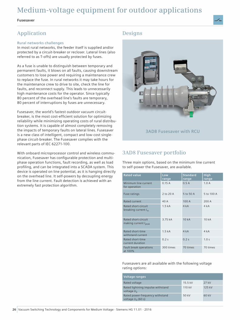
Designs
3AD8 Fusesaver with RCU
3AD8 Fusesaver portfolio
Rated value Low range
Standard range
High range
Minimum line current for operation
0.15 A 0.5 A 1.0 A
Fuse ratings 2 to 20 A 5 to 50 A 5 to 100 A
Rated current 40 A 100 A 200 ARated short-circuit breaking current Isc
1.5 kA 4 kA 4 kA
Rated short-circuit making current Ipeak
3.75 kA 10 kA 10 kA
Rated short-time withstand current
1.5 kA 4 kA 4 kA
Rated short-time current duration
0.2 s 0.2 s 1.0 s
Fault break operations at 100%
300 times 70 times 70 times
Voltage ranges
Rated voltage 15.5 kV 27 kVRated lightning impulse withstand voltage Up
110 kV 125 kV
Rated power-frequency withstand voltage Ud (60 s)
50 kV 60 kV
Three main options, based on the minimum line current to self-power the Fusesaver, are available.
Fusesavers are all available with the following voltage rating options:
27Vacuum Switching Technology and Components for Medium Voltage · Siemens HG 11.01 · 2016
Medium-voltage equipment for outdoor applicationsFusesaver
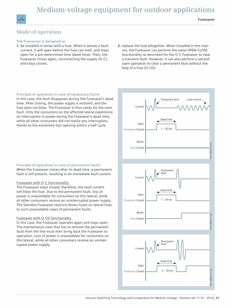
Principle of operation in case of temporary faultsIn this case, the fault disappears during the Fusesaver’s dead time. After closing, the power supply is restored, and the fuse does not blow. The Fusesaver is thus ready for the next fault. Only the consumers on the affected lateral experience an interruption in power during the Fusesaver’s dead time, while all other consumers did not notice any interruption, thanks to the extremely fast opening within a half cycle.
HG
11-2
862a
_en
eps
Fusesaver Closed
Blown
Fuse Closed
Open
Current
Dead time
1 – 30 sec
Temporary fault Load current
HG
11-2
863a
_en
eps
Fusesaver Closed
Blown
Fuse Closed
Open
Current
Dead time
1 – 30 sec
Permanent fault
HG
11-2
863a
1_en
eps
Fusesaver Closed
Open
Current
Dead time
2 – 30 sec
Permanent fault
The Fusesaver is designed to1. be installed in series with a fuse. When it senses a fault
current, it will open before the fuse can melt, and stays open for a pre-determined time (dead time). Then, the Fusesaver closes again, reconnecting the supply (O-C), and stays closed.
Principle of operation in case of permanent faultsWhen the Fusesaver closes after its dead time, a permanent fault is still present, resulting in an immediate fault current.
Fusesaver with O-C functionality The Fusesaver stays closed; therefore, the fault current will blow the fuse. Due to the permanent fault, loss of power is unavoidable for consumers on this lateral, while all other consumers receive an uninterrupted power supply. The Siemens Fusesaver restricts blown fuses on lateral lines to such unavoidable cases of permanent faults.
Fusesaver with O-CO functionality In this case, the Fusesaver operates again and stays open. The maintenance crew that has to remove the permanent fault from the line must then bring back the Fusesaver to operation. Loss of power is unavoidable for consumers on this lateral, while all other consumers receive an uninter-rupted power supply.
2. replace the fuse altogether. When installed in this man-ner, the Fusesaver can perform the same OPEN-CLOSE functionality as described for the O-C Fusesaver to clear a transient fault. However, it can also perform a second open operation to clear a permanent fault without the help of a fuse (O-CO).
Mode of operation
28 Vacuum Switching Technology and Components for Medium Voltage · Siemens HG 11.01 · 2016
Medium-voltage equipmentSurge arresters and limiters
Application
Surge arresters and limiters protect operational equipment both from external overvoltages caused by lightning strikes in overhead lines and from internal overvoltages produced by switching operations or earth faults. Normally, the arrest-er is installed between phase and earth, but also between the phases in some applications. The built-in stack of non-linear, voltage-dependent resistors (varistors) made of metal oxide (MO) becomes conductive from a defined overvoltage limit value onwards, so that the surge can be discharged through the arrester. When the overvoltage underflows this limit value, called discharge voltage, the varistors return to their original resistance value, so that only a so-called leakage current of a few mA flows. In continuous operation, this leakage current heats up the MO elements, and thus the arrester. Therefore, the device must be designed according to the neutral-point treatment of the system, or the con-nection of the arresters, in order to prevent impermissible heating of the arrester.
In contrast to the normal surge arrester, the surge limiter contains a series gap in addition to the MO resistor stack. If the energy generated by the overvoltage is large enough, the series gap ignites, and the overvoltage can be dis-charged to earth until the series gap extinguishes and the varistors return to their non-conductive state. This process is repeated again and again throughout the entire duration of the fault. This makes it possible to design the device with a considerably lower discharge voltage as a conventional surge arrester, without having a too high temperature rise in normal operation. Limiters are especially useful for the protection of motors with – normally – a poor dielectric strength. To guarantee a sufficient protective function, the discharge voltage value of the arresters or limiters must not
Designs
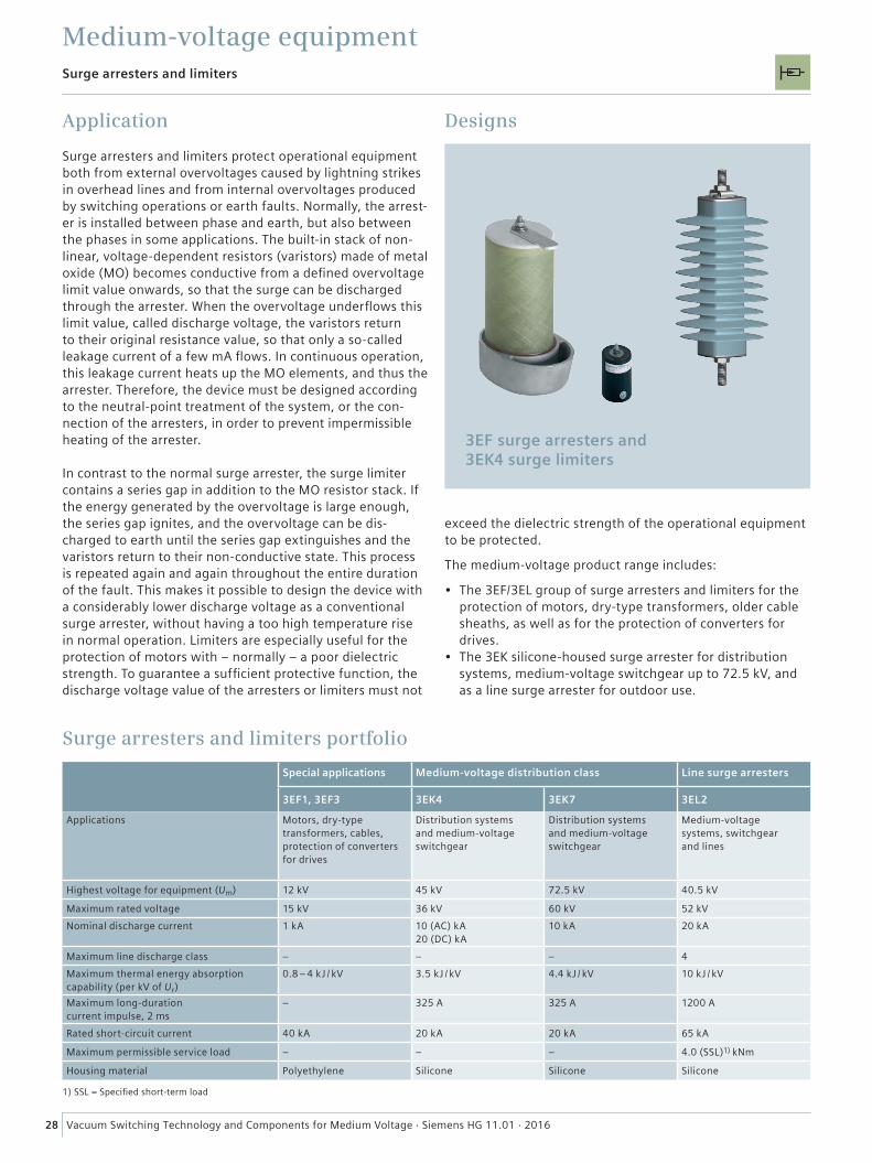
3EF surge arresters and 3EK4 surge limiters
Surge arresters and limiters portfolio
Special applications Medium-voltage distribution class Line surge arresters
3EF1, 3EF3 3EK4 3EK7 3EL2
Applications Motors, dry-type transformers, cables, protection of converters for drives
Distribution systems and medium-voltage switchgear
Distribution systems and medium-voltage switchgear
Medium-voltage systems, switchgear and lines
Highest voltage for equipment (Um) 12 kV 45 kV 72.5 kV 40.5 kV
Maximum rated voltage 15 kV 36 kV 60 kV 52 kVNominal discharge current 1 kA 10 (AC) kA
20 (DC) kA10 kA 20 kA
Maximum line discharge class – – – 4Maximum thermal energy absorption capability (per kV of Ur)
0.8 – 4 kJ / kV 3.5 kJ / kV 4.4 kJ / kV 10 kJ / kV
Maximum long-duration current impulse, 2 ms
– 325 A 325 A 1200 A
Rated short-circuit current 40 kA 20 kA 20 kA 65 kA
Maximum permissible service load – – – 4.0 (SSL)1) kNm
Housing material Polyethylene Silicone Silicone Silicone
exceed the dielectric strength of the operational equipment to be protected.
The medium-voltage product range includes:
• The 3EF/3EL group of surge arresters and limiters for the protection of motors, dry-type transformers, older cable sheaths, as well as for the protection of converters for drives.
• The 3EK silicone-housed surge arrester for distribution systems, medium-voltage switchgear up to 72.5 kV, and as a line surge arrester for outdoor use.
1) SSL = Specified short-term load

29Vacuum Switching Technology and Components for Medium Voltage · Siemens HG 11.01 · 2016
Medium-voltage equipmentFuses
Designs
Fuse-links
Application
HV HRC (high-voltage high-rupturing capacity) fuses are used for short-circuit protection in switchgear. They pro-tect devices and parts of the system such as transformers, motors, capacitors, voltage transformers, and cable feed-ers against the dynamic and thermal effects of high short-circuit currents by limiting and breaking them when they arise. Fuses consist of the fuse-base and the fuse-links. The fuse-links are used for one single breaking of fault currents; then they must be replaced. In a switch-fuse combination, the thermal striker tripping of the fuse prevents the ther-mal destruction of the fuse. The fuses are suitable both for indoor and outdoor switchgear. They are fitted in fuse-bases available as individual 1-phase or 3-phase components, or as built-on components in combination with the corresponding switching device.
Fuse portfolio for indoor and outdoor applications
Rated voltage
Rated current
Rated breaking current
Mounting length (reference dimension)
in mm
kV A kA 192 292 442 537
7.2 6.3 – 100 63 ◼ – – –
125 – 160 63 – – ◼ –
200 – 315 50 – – ◼ –
12 6.3 – 100 63 – ◼ – –
125 – 160 63 – – ◼ –
24 6.3 – 100 63 – – ◼ –
36 6.3 – 100 40 – – – ◼
Rated voltage
Rated current
Rated breaking current
Mounting length (reference dimension)
in mm
kV A kA 192 292 442 537
7.2 50 – 315 50 – – ◼ –
12 100 – 200 50 – ◼ ◼ –
HV HRC fuse-links as back-up fuses HV HRC fuse-links for motor protection
30 Vacuum Switching Technology and Components for Medium Voltage · Siemens HG 11.01 · 2016
Medium-voltage equipmentProtection and measuring transformers
Application
The task of instrument transformers is to transform high currents and voltages proportionally and in-phase into small current or voltage values for measuring or protection purposes. So they are used either to measure and record the transmitted power, or to feed protection devices with evalu-able signals, which enable the protection device to e.g. trip a switching device depending on the situation. Furthermore, they isolate the connected measuring or protection equip-ment electrically against live parts of the switchgear.
Current transformersCurrent transformers carry the full rated current on the primary side. Devices connected on the secondary side are series-connected. Current transformers can have several secondary windings with magnetically separated cores of the same or different characteristics. For example, they can be equipped with two measuring cores of different accuracy class, or with measuring and protection cores with differ-ent accuracy limit factors. Due to the risk of overvoltages, current transformers must not be operated with open secondary terminals, but only in short circuit or with the burden of the measuring equipment.
Voltage transformersVoltage transformers have only one iron core, and are nor-mally designed with one secondary winding only. If neces-sary, single-phase voltage transformers are provided with an additional residual voltage winding (earth-fault winding) beside the secondary winding (measuring winding). In contrast to current transformers, voltage transformers must never be short-circuited on the secondary side. The earth-side terminal of the primary winding is effectively earthed in the terminal box, and must not be removed during operation.
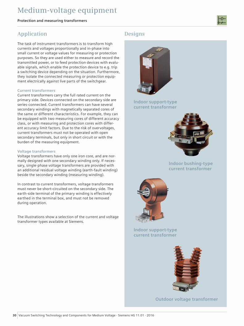
The illustrations show a selection of the current and voltage transformer types available at Siemens.
Designs
Indoor bushing-type current transformer
Indoor support-type current transformer
Outdoor voltage transformer
Indoor support-type current transformer
31Vacuum Switching Technology and Components for Medium Voltage · Siemens HG 11.01 · 2016
Medium-voltage equipmentAuxiliary switches
Application
The auxiliary switch is a switch to be operated mechanically for a short or continuous contact command. It is integrated in the secondary circuit of circuit-breakers of different characteristics as well as in electromagnetic interlocking systems, and is used
• for mutual electrical interlocking of the systems• for operation of auxiliary contactors, magnet coils, and
releases• for operation of motor operating mechanisms.
In Siemens switching devices it is used as a positively driven auxiliary switch.
Properties
• Auxiliary switch without latches and stops, for mechanical operation
• Can be used for any rotation angles• Can be ordered with switching levels from 2 to 26;
whereby these can be configured individually.
The switching levels can be freely configured as NC, NO or changeover contacts. Moreover, different switching angles and contact overlappings can be selected.
The device conforms to the standards IEV 947 Part 3, Part 5-1 and DIN VDE 0660 Part 107, as well as IEC 721 Part 3-3.
Designs
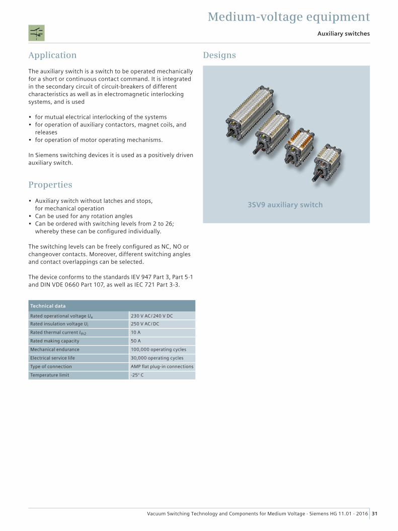
3SV9 auxiliary switch
Technical data
Rated operational voltage Ue 230 V AC / 240 V DCRated insulation voltage Ui 250 V AC / DC
Rated thermal current Ith2 10 A
Rated making capacity 50 A
Mechanical endurance 100,000 operating cycles
Electrical service life 30,000 operating cycles
Type of connection AMP flat plug-in connections
Temperature limit -25° C
32 Vacuum Switching Technology and Components for Medium Voltage · Siemens HG 11.01 · 2016
GuideCatalog overview
For more information about the switching devices, please refer to the following catalogs:
SION Vacuum Circuit-Breakers 3AE5 and 3AE1
Catalog HG 11.02
3AH5 Vacuum Circuit-Breakers
Catalog HG 11.05
3AH3 Vacuum Circuit-Breakers
Catalog HG 11.03
3AH4 Vacuum Circuit-Breakers
Catalog HG 11.04
3AH47 Vacuum Circuit-Breakers for Traction Applications
Catalog HG 11.52
3AK7 Vacuum Circuit-Breakers
Catalog HG 11.06

33Vacuum Switching Technology and Components for Medium Voltage · Siemens HG 11.01 · 2016
Catalog overview
Guide
Siemens Vacuum Recloser 3AD
Catalog HG 11.42
Siemens Fusesaver and Remote Control Unit 3AD8
Catalog HG 11.43
3TL Vacuum Contactors
Catalog HG 11.21
Vacuum Circuit- Breakers for Generator Switching Applications
Brochure
Type SDV7 distribution circuit breaker family
Type SDV7 distribution circuit breaker family15.5 kV to 38.0 kV
Answers for infrastructure.
www.usa.siemens.com/sdv7
Brochure
3AF – Outdoor Vacuum Circuit-Breaker up to 40.5 kV
Brochure
34 Vacuum Switching Technology and Components for Medium Voltage · Siemens HG 11.01 · 2016
GuideCatalog overview
Contactor-Fuse Combination 3TL62/63/66
Catalog HG 11.22
3CJ2 Switch-Disconnectors
Catalog HG 12.21
3EE Surge Arresters 3EF Surge Limiters
Catalog HG 21
For more information, please refer to the "Power Engineering Guide" and to the "Planning Guide HG 11.13" (in German only)
For more information about the switching devices, please refer to the following catalogs (cont.):

35Vacuum Switching Technology and Components for Medium Voltage · Siemens HG 11.01 · 2016
Notes

2016
Published by Siemens AG 2016
Energy Management Division Medium Voltage & Systems Low Voltage & Products Nonnendammallee 104 13623 Berlin, Germany
For more information, please contact our Customer Support Center. Phone: +49 180 524 70 00 Fax: +49 180 524 24 71 (Charges depending on provider) E-mail: [email protected] www.siemens.com/mediumvoltage
Article No. EMMS-K1511-A011-A2-7600 Printed in Germany Dispo 30408 PU 14000 / 67207 KG 04160.5
Subject to changes and errors.
The information given in this document only contains general descriptions and/or performance features which may not always specifically reflect those described, or which may undergo modifica-tion in the course of further development of the products. The requested performance features are binding only when they are expressly agreed upon in the concluded contract.