Vacuum / cryo links Mechanical design issues Jo van den Brand, Martin Doets Nikhef...
16
Vacuum / cryo links Mechanical design issues Jo van den Brand, Martin Doets Nikhef [email protected] [email protected] Cascina, January 21, 2010
-
Upload
beatrix-may -
Category
Documents
-
view
221 -
download
4
Transcript of Vacuum / cryo links Mechanical design issues Jo van den Brand, Martin Doets Nikhef...
Vacuum / cryo links
Mechanical design issues
Jo van den Brand, Martin DoetsNikhef
[email protected] [email protected] Cascina, January 21, 2010

West end
Conceptual designAntonio (March, 2009)

West input
Rotated DN1000 standard valve
Options: - small or large link: small is baseline - small link: small or large diameter, length

West input
Short cryo link
DN630 standard valve (D = 650 mm)
DN1000 standard valve
Ion pumps
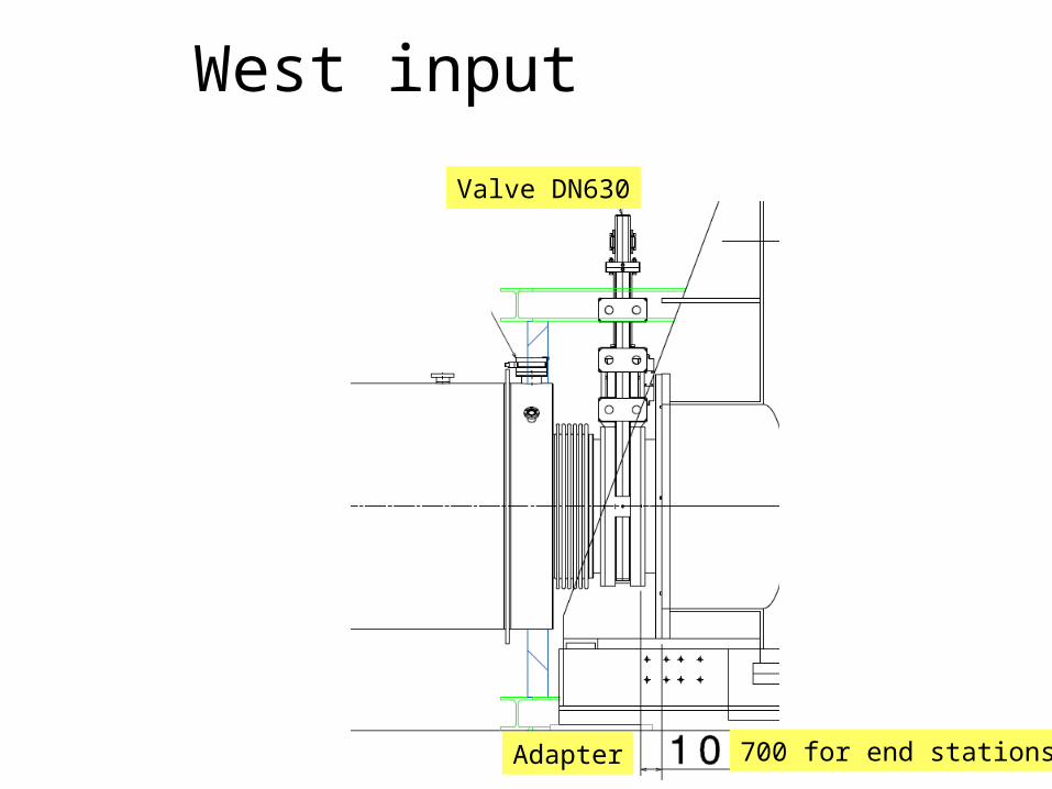
West input
Valve DN630
Adapter 700 for end stations
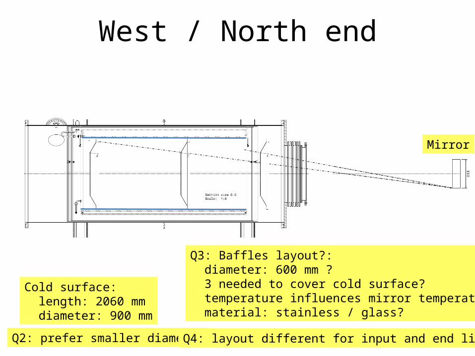
West / North end
Cold surface: length: 2060 mm diameter: 900 mm
Q3: Baffles layout?: diameter: 600 mm ? 3 needed to cover cold surface? temperature influences mirror temperature material: stainless / glass?
Mirror
Q2: prefer smaller diameter Q4: layout different for input and end links

Top view
L = 3490 mmD = 1208 mm
S.St. 304L Reinforcement ribs
Hydroformed bellows

End view and cross section
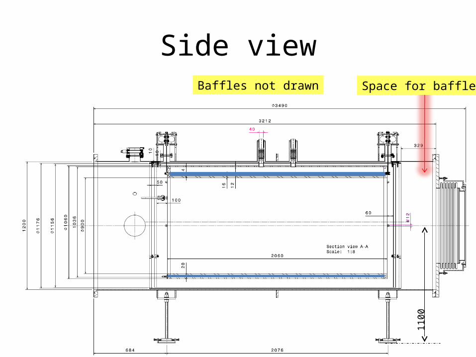
Side viewSpace for baffles
1100
Baffles not drawn

Side view

Design detail: suspensions
Movable part
Fixed part (to rib / vessel)
Rib
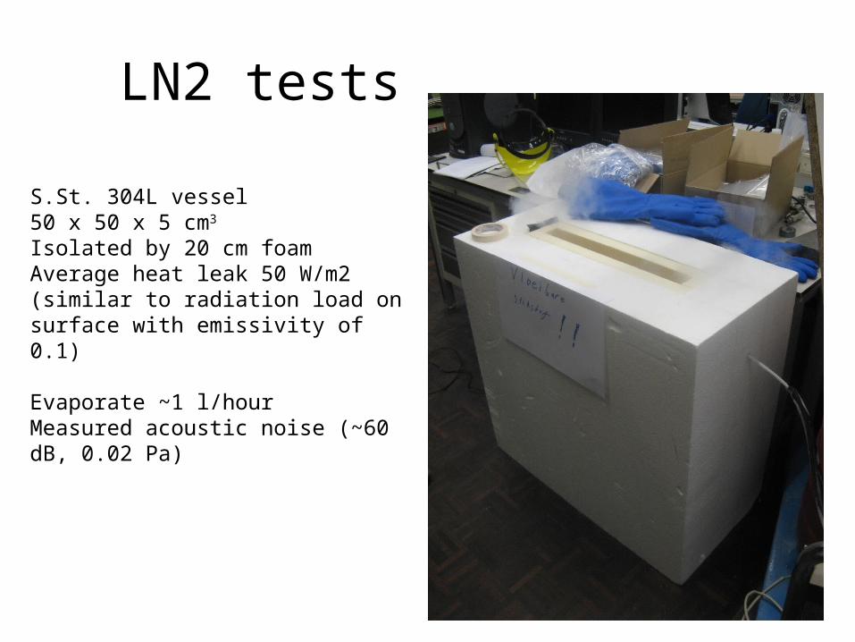
LN2 tests
S.St. 304L vessel50 x 50 x 5 cm3
Isolated by 20 cm foamAverage heat leak 50 W/m2(similar to radiation load on surface with emissivity of 0.1)
Evaporate ~1 l/hourMeasured acoustic noise (~60 dB, 0.02 Pa)
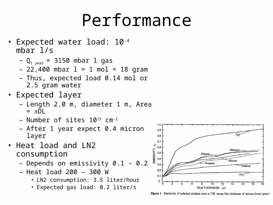
Performance• Expected water load: 10-4 mbar l/s
– Q1 year = 3150 mbar l gas– 22,400 mbar l = 1 mol = 18 gram– Thus, expected load 0.14 mol or 2.5
gram water• Expected layer
– Length 2.0 m, diameter 1 m, Area = DL
– Number of sites 1015 cm-2
– After 1 year expect 0.4 micron layer• Heat load and LN2 consumption
– Depends on emissivity 0.1 – 0.2 – Heat load 200 – 300 W
• LN2 consumption: 3.5 liter/hour• Expected gas load: 0.2 liter/s

Logistics• Quotations: total 789 kEuro (939 kEuro including VAT)
– R&D phase 10 kEuro– Design & engineering 45 kEuro– Short link 125 kEuro x
4• Standard phase separator• Simple LN2 extraction• Simplification of separation rings for LN2 circuit
– Valve DN630 39.8 kEuro x 4• ex VAT• ex 7.5% discount
– Other items 75 kEuro• Valve DN100• Turbo molecular pump station• Gauges, control, tubing, etc.
• Manpower ~ 5 fte– Mechanical and control system design– Construction of (support) structures, etc– Testing– Installation

Summary• Preliminary design for short cryo links
– Length 2.0 m, diameter 0.9 m– Capacity > 1 year for 1 micron layer– Reduced heat load: 200 – 300 W
• LN2 consumption: 3.5 liter/hour• Low gas load (0.2 liter/s), less bubbles, less noise
– Thermal effect on mirrors acceptable– Reduced cost
• Test set-up– Operations
• External vs closed loop condensor• Consumption versus coverage (emissivity development)• Control issues (normal running, regeneration, …)
– Bubble induced noise

Next Steps
• Optical interfaces are being defined = trap length and diameter . Towers position in May/June, the explicit approval on diameter is expected in shorter time
• Trap design is being optimized vs bubbling noise • The order of the first trap (prototype) shall be
shifted in the second half of 2010, without affecting the milestone ‘completion’ of Nov2012.