Virgo change request - Nikhef · VIRGO CHRQ xxx/yyyy Page: 1/18 Virgo change request Title:...
18
VIRGO CHRQ xxx/yyyy Page: 1/18 Virgo change request Title: Responsible: Name: J.F.J. van den Brand Email [email protected] Institution: Nikhef National Institute for Subatomic Physics Procedure start date: 01/07/2010 Procedure end date: 31/12/2010 Document version v01r02 Version date 01/10/2010 EIB seismic attenuation system Opmerking [MP1]: Never change it after the sending to the detector coordinator Opmerking [MP2]: To be inserted only by the detector coordinator Opmerking [MP3]: change the release index for minor changes and the version index for major changes. Start from V01. Opmerking [MP4]: Update this field any time you produce a new release or version
Transcript of Virgo change request - Nikhef · VIRGO CHRQ xxx/yyyy Page: 1/18 Virgo change request Title:...
VIRGO CHRQ xxx/yyyy
Page: 1/18
Virgo change request
Title:
Responsible: Name: J.F.J. van den Brand
Email [email protected]
Institution: Nikhef National Institute for Subatomic Physics
Procedure start date: 01/07/2010
Procedure end date: 31/12/2010
Document version v01r02
Version date 01/10/2010
EIB seismic attenuation system
Opmerking [MP1]: Never change it
after the sending to the detector coordinator
Opmerking [MP2]: To be inserted only
by the detector coordinator
Opmerking [MP3]: change the release
index for minor changes and the version
index for major changes. Start from V01.
Opmerking [MP4]: Update this field
any time you produce a new release or version
VIRGO CHRQ xxx/yyyy
Page: 2/18
Authors Name Institution email
Thomas Bauer Nikhef [email protected]
Mark Beker (PhD student) Nikhef [email protected]
Mathieu Blom (PhD student) Nikhef [email protected]
Jo van den Brand (PI) Nikhef [email protected]
David Rabeling (postdoc) Nikhef [email protected]
Eric Hennes Nikhef [email protected]
Richard Rosing Nikhef [email protected]
Michiel Jaspers Nikhef [email protected]
Piet de Groen Nikhef [email protected]
Frans Mul (techn. coordinator) Nikhef/VU Amsterdam [email protected]
Joost Rosier Vrije Universiteit Amsterdam [email protected]
Bert Clairbois Vrije Universiteit Amsterdam [email protected]
Wim Gotink Nikhef [email protected]
Alessandro Bertolini Albert Einstein Institute [email protected]
Henk Jan Bulten Nikhef [email protected]
Willem Kuilman Nikhef [email protected]
Gert Jan Mul Nikhef [email protected]
Gerrit Brouwer Nikhef [email protected]
Jaap Kuijt Nikhef [email protected]
Index Authors ........................................................................................................................................... 2
Index ............................................................................................................................................... 2 Abstract .......................................................................................................................................... 3
Motivations ..................................................................................................................................... 3 Technical description ...................................................................................................................... 5
Task 1 ....................................................................................................................................... 11 Task 2 ....................................................................................................................................... 11
Task 3 ....................................................................................................................................... 11 Task 4 ....................................................................................................................................... 11
Task 5 ....................................................................................................................................... 11 Task 6 ....................................................................................................................................... 11
Deliverable 1 ............................................................................................................................. 11 Deliverable 2 ............................................................................................................................. 11
Involved Virgo sub-systems .......................................................................................................... 12 Involved EGO infrastructures ........................................................................................................ 12
Planning ........................................................................................................................................ 12 Planning ........................................................................................................................................ 14
Budget .......................................................................................................................................... 15 Document/Procedure history ......................................................................................................... 16
Annexes ........................................................................................................................................ 17 Automatic information fields......................................................................................................... 18
VIRGO CHRQ xxx/yyyy
Page: 3/18
Abstract The EIB motion due to seismic noise causes beam jitter and alignment noise that are expected to
limit the sensitivity of Virgo after installation of the monolithic suspensions. We propose to install a
seismic attenuation system that should lower the noise of the EIB by at least a factor of 100 above
10 Hz. In this manner, the full potential of V+MS in the low frequency domain can be exploited.
Motivations Several benches are used in Virgo to support optical systems. The so-called external benches are
located outside the vacuum system, and are used to support optical tables near the end mirrors:
west-end bench (WEB) and north-end bench (NEB), and for the injection (External Injection
Bench, EIB) and detection (EDB) benches.
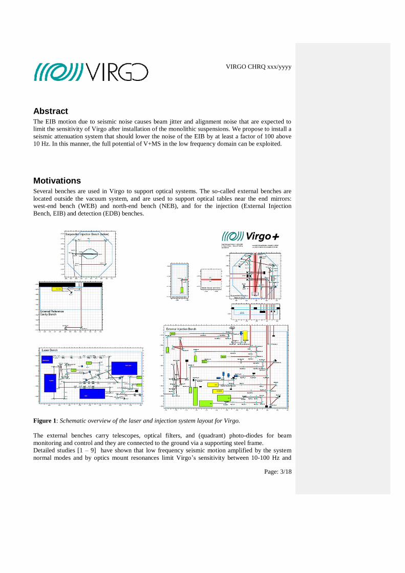
Figure 1: Schematic overview of the laser and injection system layout for Virgo.
The external benches carry telescopes, optical filters, and (quadrant) photo-diodes for beam
monitoring and control and they are connected to the ground via a supporting steel frame.
Detailed studies [1 – 9] have shown that low frequency seismic motion amplified by the system
normal modes and by optics mount resonances limit Virgo’s sensitivity between 10-100 Hz and
VIRGO CHRQ xxx/yyyy
Page: 4/18
200-300 Hz. The benches need to provide sufficient vibration isolation to obtain the sensitivity
required for Virgo. Nikhef intends to implement vibration isolation for several of these external
benches.
Fig. 1 shows the laser and injection system layout for Virgo. The beam originates from the laser
bench and is conditioned in the external injection bench. The beam enters the Virgo vacuum system
and falls on the suspended injection bench. In order to filter motions from the external benches, the
beam resonates in the input-mode cleaner. Subsequently, the beam is injected into the Virgo
interferometer (ITF).
It is unavoidable that some light is diffused by optical components placed on the bench. When the
transmittance of end-mirror is denoted Tmirror, the noise seen at the ITF output is then
The coupling factor G is determined by the transmittance of the mirror (about 40 ppm), the fraction
of back scattered intensity (about 10-8
), and the Finesse F of the cavity (880 for Advanced Virgo
[3]). The coupling factors have been determined [4] and are given in Table 1.1.
Table 1.1. Coupling factors for the various external benches. Numbers are in units of 10-21
.
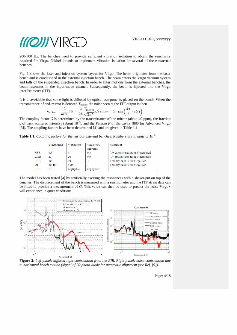
The model has been tested [4] by artificially exciting the resonances with a shaker put on top of the
benches. The displacement of the bench is measured with a seismometer and the ITF strain data can
be fitted to provide a measurement of G. This value can then be used to predict the noise Virgo+
will experience in quiet conditions.
Figure 2: Left panel: diffused light contribution from the EIB. Right panel: noise contribution due
to horizontal bench motion (signal of B2 photo-diode for automatic alignment (see Ref. [9]).
VIRGO CHRQ xxx/yyyy
Page: 5/18
Figure 2 shows that the EIB is a source of considerable noise between 16 and 100 Hz in the
sensitivity curve of Virgo+ (see Virgo notes [6 - 9]). Besides the noise contribution due to diffused
light, the operation is hampered by the horizontal EIB motion. Figure 3 shows that the EIB vertical
vibrations generate beam jitter (movement of the input beam with respect to the IFO axis).
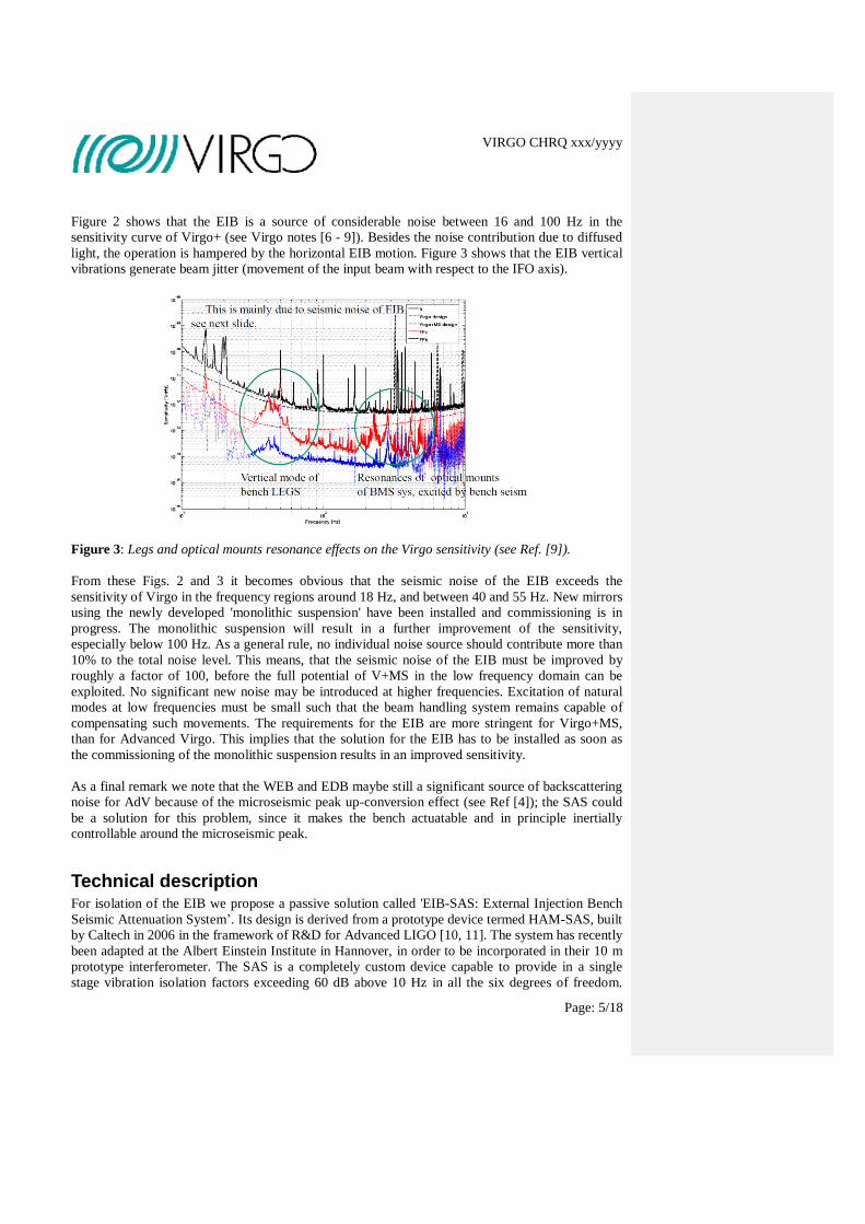
Figure 3: Legs and optical mounts resonance effects on the Virgo sensitivity (see Ref. [9]).
From these Figs. 2 and 3 it becomes obvious that the seismic noise of the EIB exceeds the
sensitivity of Virgo in the frequency regions around 18 Hz, and between 40 and 55 Hz. New mirrors
using the newly developed 'monolithic suspension' have been installed and commissioning is in
progress. The monolithic suspension will result in a further improvement of the sensitivity,
especially below 100 Hz. As a general rule, no individual noise source should contribute more than
10% to the total noise level. This means, that the seismic noise of the EIB must be improved by
roughly a factor of 100, before the full potential of V+MS in the low frequency domain can be
exploited. No significant new noise may be introduced at higher frequencies. Excitation of natural
modes at low frequencies must be small such that the beam handling system remains capable of
compensating such movements. The requirements for the EIB are more stringent for Virgo+MS,
than for Advanced Virgo. This implies that the solution for the EIB has to be installed as soon as
the commissioning of the monolithic suspension results in an improved sensitivity.
As a final remark we note that the WEB and EDB maybe still a significant source of backscattering
noise for AdV because of the microseismic peak up-conversion effect (see Ref [4]); the SAS could
be a solution for this problem, since it makes the bench actuatable and in principle inertially
controllable around the microseismic peak.
Technical description For isolation of the EIB we propose a passive solution called 'EIB-SAS: External Injection Bench
Seismic Attenuation System’. Its design is derived from a prototype device termed HAM-SAS, built
by Caltech in 2006 in the framework of R&D for Advanced LIGO [10, 11]. The system has recently
been adapted at the Albert Einstein Institute in Hannover, in order to be incorporated in their 10 m
prototype interferometer. The SAS is a completely custom device capable to provide in a single
stage vibration isolation factors exceeding 60 dB above 10 Hz in all the six degrees of freedom.
VIRGO CHRQ xxx/yyyy
Page: 6/18
This is not achievable, to our knowledge, by any existing commercial or laboratory developed
system (note, that we have tested TMC’s Stacis system at Nikhef and evaluated MECAL’s
Hummingbird system).
In EIB-SAS the seismic attenuation is obtained passively using the properties of the mechanical
oscillators which attenuate, as second-order low pass filters, above their natural frequency. The
table operates with low natural frequencies, 0.05 Hz in horizontal and 0.2 Hz in vertical, using a
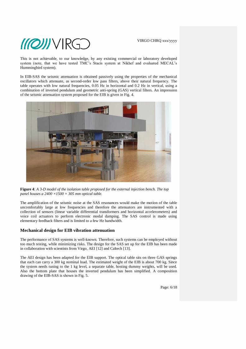
combination of inverted pendulum and geometric anti-spring (GAS) vertical filters. An impression
of the seismic attenuation system proposed for the EIB is given in Fig. 4.
Figure 4: A 3-D model of the isolation table proposed for the external injection bench. The top
panel houses a 2400 ×1500 × 305 mm optical table.
The amplification of the seismic noise at the SAS resonances would make the motion of the table
uncomfortably large at low frequencies and therefore the attenuators are instrumented with a
collection of sensors (linear variable differential transformers and horizontal accelerometers) and
voice coil actuators to perform electronic modal damping. The SAS control is made using
elementary feedback filters and is limited to a few Hz bandwidth.
Mechanical design for EIB vibration attenuation
The performance of SAS systems is well-known. Therefore, such systems can be employed without
too much testing, while minimizing risks. The design for the SAS set up for the EIB has been made
in collaboration with scientists from Virgo, AEI [12] and Caltech [13].
The AEI design has been adapted for the EIB support. The optical table sits on three GAS springs
that each can carry a 300 kg nominal load. The estimated weight of the EIB is about 700 kg. Since
the system needs tuning to the 1 kg level, a separate table, hosting dummy weights, will be used.
Also the bottom plate that houses the inverted pendulum has been simplified. A composition
drawing of the EIB-SAS is shown in Fig. 5.
VIRGO CHRQ xxx/yyyy
Page: 7/18
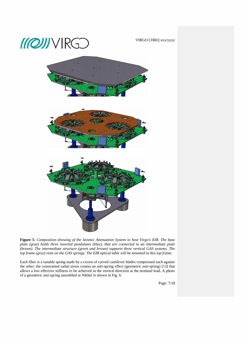
Figure 5: Composition drawing of the Seismic Attenuation System to host Virgo's EIB. The base
plate (gray) holds three inverted pendulums (blue), that are connected to an intermediate plate
(brown). The intermediate structure (green and brown) supports three vertical GAS systems. The
top frame (grey) rests on the GAS springs. The EIB optical table will be mounted to this top frame.
Each filter is a tunable spring made by a crown of curved cantilever blades compressed each against
the other: the constrained radial stress creates an anti-spring effect (geometric anti-spring) [13] that
allows a low effective stiffness to be achieved in the vertical direction at the nominal load. A photo
of a geometric anti-spring assembled at Nikhef is shown in Fig. 6.
VIRGO CHRQ xxx/yyyy
Page: 8/18
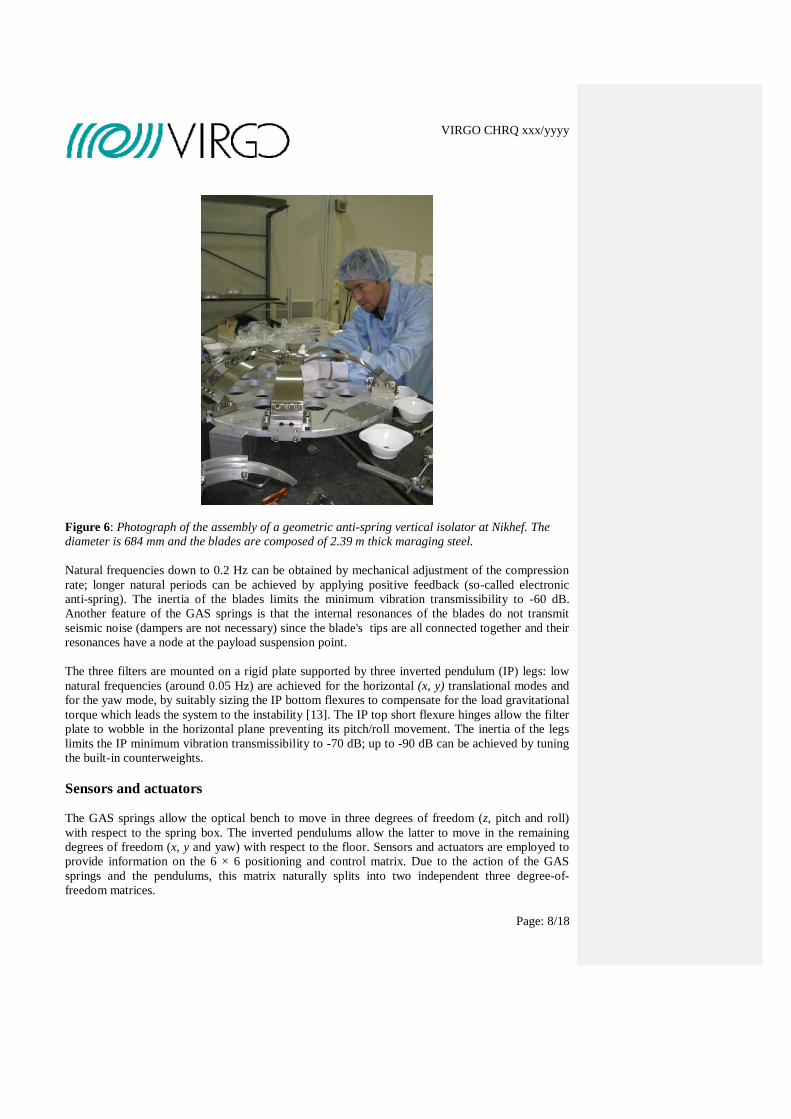
Figure 6: Photograph of the assembly of a geometric anti-spring vertical isolator at Nikhef. The
diameter is 684 mm and the blades are composed of 2.39 m thick maraging steel.
Natural frequencies down to 0.2 Hz can be obtained by mechanical adjustment of the compression
rate; longer natural periods can be achieved by applying positive feedback (so-called electronic
anti-spring). The inertia of the blades limits the minimum vibration transmissibility to -60 dB.
Another feature of the GAS springs is that the internal resonances of the blades do not transmit
seismic noise (dampers are not necessary) since the blade's tips are all connected together and their
resonances have a node at the payload suspension point.
The three filters are mounted on a rigid plate supported by three inverted pendulum (IP) legs: low
natural frequencies (around 0.05 Hz) are achieved for the horizontal (x, y) translational modes and
for the yaw mode, by suitably sizing the IP bottom flexures to compensate for the load gravitational
torque which leads the system to the instability [13]. The IP top short flexure hinges allow the filter
plate to wobble in the horizontal plane preventing its pitch/roll movement. The inertia of the legs
limits the IP minimum vibration transmissibility to -70 dB; up to -90 dB can be achieved by tuning
the built-in counterweights.
Sensors and actuators
The GAS springs allow the optical bench to move in three degrees of freedom (z, pitch and roll)
with respect to the spring box. The inverted pendulums allow the latter to move in the remaining
degrees of freedom (x, y and yaw) with respect to the floor. Sensors and actuators are employed to
provide information on the 6 × 6 positioning and control matrix. Due to the action of the GAS
springs and the pendulums, this matrix naturally splits into two independent three degree-of-
freedom matrices.
VIRGO CHRQ xxx/yyyy
Page: 9/18
.
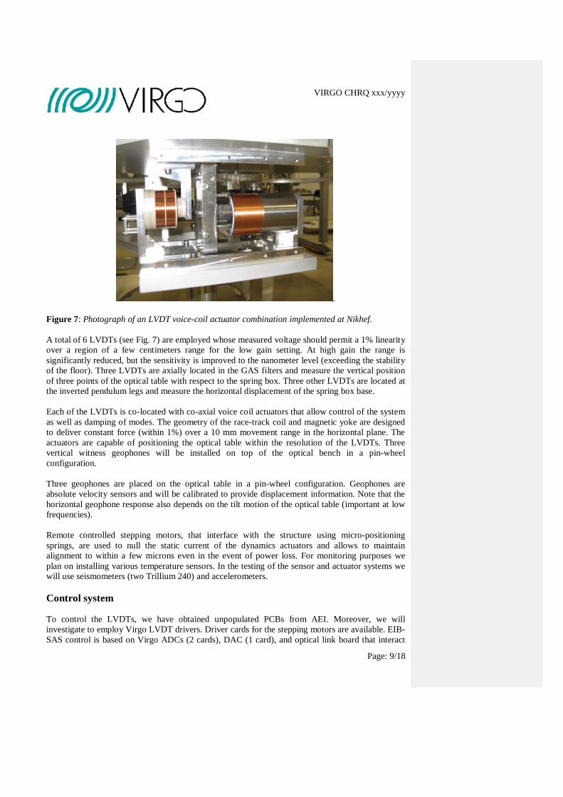
Figure 7: Photograph of an LVDT voice-coil actuator combination implemented at Nikhef.
A total of 6 LVDTs (see Fig. 7) are employed whose measured voltage should permit a 1% linearity
over a region of a few centimeters range for the low gain setting. At high gain the range is
significantly reduced, but the sensitivity is improved to the nanometer level (exceeding the stability
of the floor). Three LVDTs are axially located in the GAS filters and measure the vertical position
of three points of the optical table with respect to the spring box. Three other LVDTs are located at
the inverted pendulum legs and measure the horizontal displacement of the spring box base.
Each of the LVDTs is co-located with co-axial voice coil actuators that allow control of the system
as well as damping of modes. The geometry of the race-track coil and magnetic yoke are designed
to deliver constant force (within 1%) over a 10 mm movement range in the horizontal plane. The
actuators are capable of positioning the optical table within the resolution of the LVDTs. Three
vertical witness geophones will be installed on top of the optical bench in a pin-wheel
configuration.
Three geophones are placed on the optical table in a pin-wheel configuration. Geophones are
absolute velocity sensors and will be calibrated to provide displacement information. Note that the
horizontal geophone response also depends on the tilt motion of the optical table (important at low
frequencies).
Remote controlled stepping motors, that interface with the structure using micro-positioning
springs, are used to null the static current of the dynamics actuators and allows to maintain
alignment to within a few microns even in the event of power loss. For monitoring purposes we
plan on installing various temperature sensors. In the testing of the sensor and actuator systems we
will use seismometers (two Trillium 240) and accelerometers.
Control system
To control the LVDTs, we have obtained unpopulated PCBs from AEI. Moreover, we will
investigate to employ Virgo LVDT drivers. Driver cards for the stepping motors are available. EIB-
SAS control is based on Virgo ADCs (2 cards), DAC (1 card), and optical link board that interact
VIRGO CHRQ xxx/yyyy
Page: 10/18
with a PC with real-time linux. The control system provides positioning of the optical table near the
optimal working point of the filters. This involves in addition to the static DC position control, a
velocity control in order to apply viscous damping of the system. The so-called EMAS (electro-
magnetic anti-spring) strategy [10] has been applied in the LIGO system through a digital feedback
control system. This allows stiffness control and resulted in lowering the vertical resonant
frequencies below 100 mHz
Expected performance
The performance of HAS-SAS has been determined in the context of LIGO R&D and also at AEI
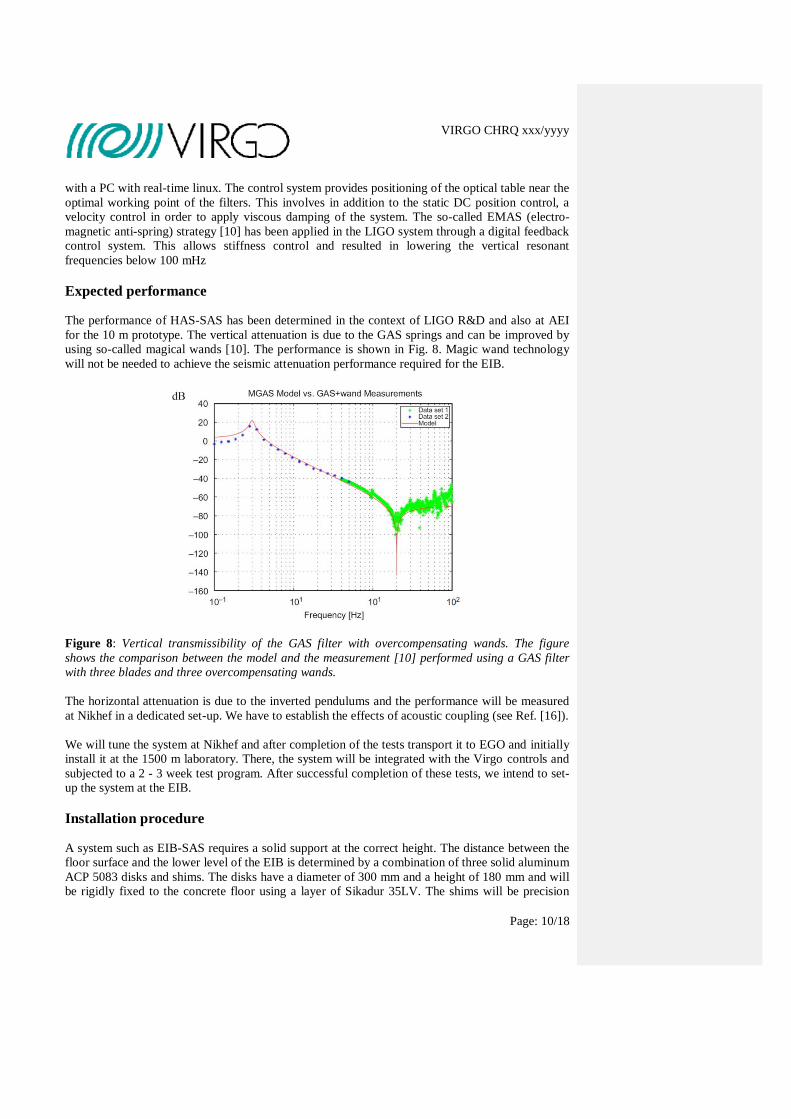
for the 10 m prototype. The vertical attenuation is due to the GAS springs and can be improved by
using so-called magical wands [10]. The performance is shown in Fig. 8. Magic wand technology
will not be needed to achieve the seismic attenuation performance required for the EIB.
Figure 8: Vertical transmissibility of the GAS filter with overcompensating wands. The figure
shows the comparison between the model and the measurement [10] performed using a GAS filter
with three blades and three overcompensating wands.
The horizontal attenuation is due to the inverted pendulums and the performance will be measured
at Nikhef in a dedicated set-up. We have to establish the effects of acoustic coupling (see Ref. [16]).
We will tune the system at Nikhef and after completion of the tests transport it to EGO and initially
install it at the 1500 m laboratory. There, the system will be integrated with the Virgo controls and
subjected to a 2 - 3 week test program. After successful completion of these tests, we intend to set-
up the system at the EIB.
Installation procedure
A system such as EIB-SAS requires a solid support at the correct height. The distance between the
floor surface and the lower level of the EIB is determined by a combination of three solid aluminum
ACP 5083 disks and shims. The disks have a diameter of 300 mm and a height of 180 mm and will
be rigidly fixed to the concrete floor using a layer of Sikadur 35LV. The shims will be precision

VIRGO CHRQ xxx/yyyy
Page: 11/18
machined to ensure correct height and leveling of the optical table of the EIB. Tests of this
technique will be performed at Nikhef. It has been verified that the floor at the location of the EIB is
strong enough for the additional weight.
Task 1
Hardware realization: Design and construction of the EIB-SAS mechanical system. Measurement
of the performance of the system. Most importantly, vertical and horizontal transfer functions are
obtained by using dedicated tuning set-ups. This allows tuning of the GAS filter and of the IP
counterweights. These measurements are performed at Nikhef.
Task 2
Integration of controls: Realization of the control system for LVDTs, geophones, voice-coil
actuators and stepping motors. Calibration of the sensors and actuators. Connection to the DAQ
system and realization of initial control software. These activities are carried out at Nikhef. After
completion of this task, the system will be shipped to the EGO site.
Task 3
On-site validation: Validation of the system at the 1500 m laboratory at the EGO site. This involves
seismic isolation tests and measurements of transfer functions. The system will be prepared for
installation in Virgo. This involves preparation of cables, integration of the control system, and
most probably partial disassembly of the EIB-SAS.
Task 4
Integration: Integration of the EIB-SAS in Virgo. This involves an alignment task that employs a
temporary reference frame for the EIB YAG beam. After installation, the EIB must be re-aligned,
cables connected, and the system must be made operative.
Task 5
Passive commissioning: Commissioning of the EIB-SAS as a passive system. This implies using its
control system to operate the system as a single stand-alone unit.
Task 6
Active commissioning: Commissioning of the EIB-SAS as an active system. Signals from the
interferometer are used in the feedback of the EIB-SAS controls.
Deliverable 1
EIB-SAS system hardware and controls at EGO.
Deliverable 2
EIB-SAS ready for integration and commissioning in Virgo.

VIRGO CHRQ xxx/yyyy
Page: 12/18
Involved Virgo sub-systems
In the following table we describe the subsystems that are involved in the realization of the EIB
vibration isolation system for Virgo. The subsystems are listed in order of decreasing
involvement (# 1 is the subsystem that we intend to modify) describing the type of consequence
on each subsystem.
# Subsystem Name Description of the involvement
1 OSD optical constraints for geometry (diffused light issue, etc.)
2 DAQ electronics and software compliance
3 INJ injection system
4 IME infrastructure (cable trays, crates, etc.)
Involved EGO infrastructures In the following we describe the infrastructures of EGO needed.
# Infrastructure Description of the involvement
1 1500 laboratory EIB-SAS installation preparations and validation
2 workshop Installation tooling
3 control group Control integration
Planning The EIB-SAS project is planned in 2010. The following considerations have to be taken into
account:
1. The EIB-SAS must be installed as soon as possible after the end of VSR3 in order to take
full advantage of the improved sensitivity of Virgo below 50 Hz.
2. The performance of EIB-SAS must be compliant with the requirements of Virgo+MS, as
Advanced Virgo maybe less demanding on the characteristics of the EIB.
3. The system must be integrated into the Virgo control system.
The different steps that must be taken in the realization of EIB-SAS, are described below, grouped
in three parts: 'finalization', 'production' and 'integration'.
Preamble
A first Virgo change request for the EIB-SAS has been prepared in the last week of June 2010. The
request has been reviewed by a dedicated committee on July 1, 2010 in Cascina/Roma. The
committee was chaired by Piero Rapagnani (Roma1, detector coordinator) and other members were
Enrico Calloni (Napoli, commissioning coordinator), Franco Frasconi (Pisa), Eric Genin (EGO,
coordinator INJ group), and Irene Fiori (Pisa).
VIRGO CHRQ xxx/yyyy
Page: 13/18
The output of the meeting was the decision to proceed with the EIB-SAS as a solution for the noise
attenuation of the EIB. The committee agreed that Nikhef would start to develop this bench, making
the first working tests at Nikhef and then bringing the apparatus on site. Before integrating the
bench into Virgo, further tests at the 1500 m laboratory were agreed upon, in order to validate the
proper functioning of the EIB-SAS and to convince the collaboration that its use in Virgo can
produce a sensitivity improvement. It was not yet decided whether the solution should count as a
Virgo+ activity or as an AdV activity (this is relevant for budgetary reasons and needs to be decided
upon in a timely fashion by the persons responsible).
Production
Production of the EIB-SAS was started in July 2010 by Galli & Morelli in Lucca, Italy. All
components were delivered to Nikhef by the middle of August 2010. Since then, assembly of the
system is in progress (Nikhef: 1.5 ME, 3 MT, 0.5 EE, 3 P) and it is expected that the system is
completed in October 2010.
In the same period the various electronic and control components have been obtained. LVDTs and
voice coil actuators were completed in September 2010. In the same month the DAQ has been set-
up and made operational. Accelerometers were acquired in September 2010. We expect that EIB-
SAS can be realized in October 2010 with integration of all control systems (and partial software).
Integration EIB-SAS
At present we aim at transporting EIB-SAS to Cascina in the third week of November 2010. The
system will then be made operational in the 1500 m laboratory by a team consisting of members
from Nikhef (1 ME, 1MT, 2 P), EGO (0.5 ME, 1 MT and 0.5 P) and Virgo (0.5 P). The system will
be validated by measuring transfer functions. We expect that 2 weeks are sufficient for this task.
After passing acceptance tests, EIB-SAS will be integrated into Virgo. Preparations for the
integration must be partially completed by then (pulling of cables, dedicated space for control
equipment must be available) and are carried out by a collaboration of Nikhef (0.5 EE) and EGO
ET (0.5 EE). The ITF must be prepared for EIB changes (Nikhef 1 P with EGO 1 P from INJ
subsystem). A workforce must be organized to carry out the installation (Nikhef 1 ME, 1 MT, 1 EE,
2 P and EGO 0.5 ME, 1 MT, 0.5 P). The hardware will then be installed and the cabling will be
implemented. The EIB must be re-aligned (Nikhef 1P and EGO 1 P from INJ subsystem). We
expect that 3 weeks are sufficient for these tasks. A detailed plan should be formulated in
collaboration with the parties involved.
After installation, the commissioning of EIB-SAS can proceed. This will be carried out in a phased
approach. In phase 1 (estimated as a 2 week activity), the system will be commissioned as a passive
unit with a separated control system. In phase 2 (estimated as a 3 week activity) signals from the
interferometer will be used in the feedback loops of the EIB-SAS control system. The
commissioning activities are expected to place a significant load on the commissioning group. A
detailed plan should be formulated in collaboration with the parties involved. Nikhef intends to be
involved in the commissioning of EIB-SAS (Nikhef PhD student, Mathieu Blom has some
experience as member of the Virgo commissioning team when stationed in Cascina).
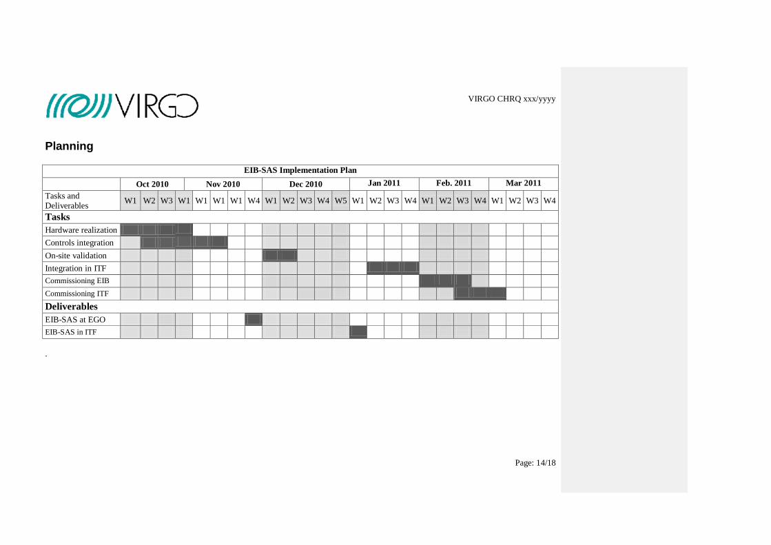
Implementation plan and maintenance
The planning is presented for the EIB-SAS in the figure below.
VIRGO CHRQ xxx/yyyy
Page: 14/18
Planning
EIB-SAS Implementation Plan
Oct 2010 Nov 2010 Dec 2010 Jan 2011 Feb. 2011 Mar 2011
Tasks and
Deliverables W1 W2 W3 W1 W1 W1 W1 W4 W1 W2 W3 W4 W5 W1 W2 W3 W4 W1 W2 W3 W4 W1 W2 W3 W4
Tasks
Hardware realization
Controls integration
On-site validation
Integration in ITF
Commissioning EIB
Commissioning ITF
Deliverables
EIB-SAS at EGO
EIB-SAS in ITF
.
VIRGO CHRQ xxx/yyyy
Page: 15/18
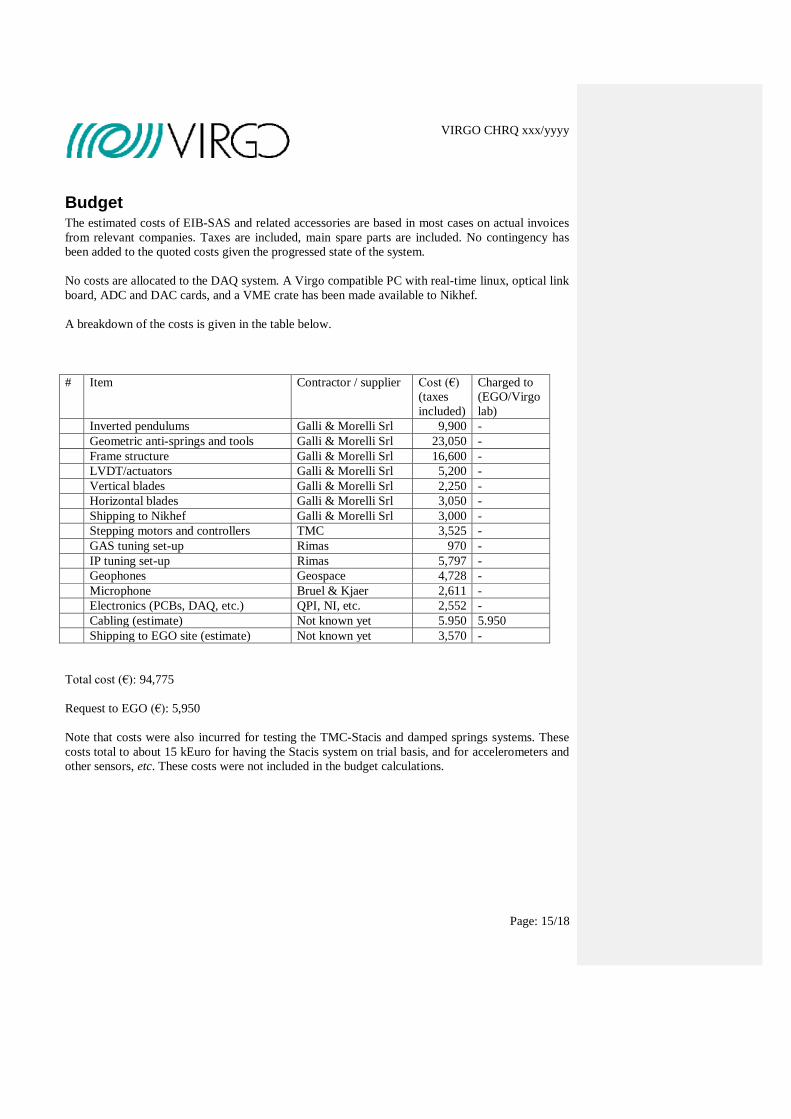
Budget The estimated costs of EIB-SAS and related accessories are based in most cases on actual invoices
from relevant companies. Taxes are included, main spare parts are included. No contingency has
been added to the quoted costs given the progressed state of the system.
No costs are allocated to the DAQ system. A Virgo compatible PC with real-time linux, optical link
board, ADC and DAC cards, and a VME crate has been made available to Nikhef.
A breakdown of the costs is given in the table below.
# Item Contractor / supplier Cost (€)
(taxes
included)
Charged to
(EGO/Virgo
lab)
Inverted pendulums Galli & Morelli Srl 9,900 -
Geometric anti-springs and tools Galli & Morelli Srl 23,050 -
Frame structure Galli & Morelli Srl 16,600 -
LVDT/actuators Galli & Morelli Srl 5,200 -
Vertical blades Galli & Morelli Srl 2,250 -
Horizontal blades Galli & Morelli Srl 3,050 -
Shipping to Nikhef Galli & Morelli Srl 3,000 -
Stepping motors and controllers TMC 3,525 -
GAS tuning set-up Rimas 970 -
IP tuning set-up Rimas 5,797 -
Geophones Geospace 4,728 -
Microphone Bruel & Kjaer 2,611 -
Electronics (PCBs, DAQ, etc.) QPI, NI, etc. 2,552 -
Cabling (estimate) Not known yet 5.950 5.950
Shipping to EGO site (estimate) Not known yet 3,570 -
Total cost (€): 94,775
Request to EGO (€): 5,950
Note that costs were also incurred for testing the TMC-Stacis and damped springs systems. These
costs total to about 15 kEuro for having the Stacis system on trial basis, and for accelerometers and
other sensors, etc. These costs were not included in the budget calculations.

VIRGO CHRQ xxx/yyyy
Page: 16/18
Document/Procedure history
Date Event Comment
27/02/2009 Start of the procedure
01/07/2010 Presentation to the detector meeting
/ change request committee
Approval was granted to Nikhef for EIB-
SAS construction
02/10/2010 New release of the document
dd/mm/yyyy Submission to the VSC
VIRGO CHRQ xxx/yyyy
Page: 17/18
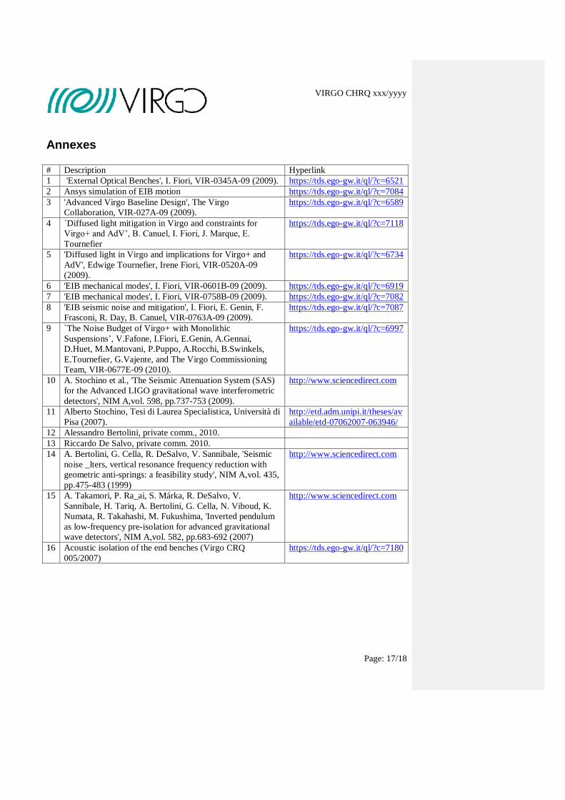
Annexes
# Description Hyperlink
1 'External Optical Benches', I. Fiori, VIR-0345A-09 (2009). https://tds.ego-gw.it/ql/?c=6521
2 Ansys simulation of EIB motion https://tds.ego-gw.it/ql/?c=7084
3 'Advanced Virgo Baseline Design', The Virgo
Collaboration, VIR-027A-09 (2009).
https://tds.ego-gw.it/ql/?c=6589
4 `Diffused light mitigation in Virgo and constraints for
Virgo+ and AdV’, B. Canuel, I. Fiori, J. Marque, E.
Tournefier
https://tds.ego-gw.it/ql/?c=7118
5 'Diffused light in Virgo and implications for Virgo+ and
AdV', Edwige Tournefier, Irene Fiori, VIR-0520A-09
(2009).
https://tds.ego-gw.it/ql/?c=6734
6 'EIB mechanical modes', I. Fiori, VIR-0601B-09 (2009). https://tds.ego-gw.it/ql/?c=6919
7 'EIB mechanical modes', I. Fiori, VIR-0758B-09 (2009). https://tds.ego-gw.it/ql/?c=7082
8 'EIB seismic noise and mitigation', I. Fiori, E. Genin, F.
Frasconi, R. Day, B. Canuel, VIR-0763A-09 (2009).
https://tds.ego-gw.it/ql/?c=7087
9 `The Noise Budget of Virgo+ with Monolithic
Suspensions’, V.Fafone, I.Fiori, E.Genin, A.Gennai,
D.Huet, M.Mantovani, P.Puppo, A.Rocchi, B.Swinkels,
E.Tournefier, G.Vajente, and The Virgo Commissioning
Team, VIR-0677E-09 (2010).
https://tds.ego-gw.it/ql/?c=6997
10 A. Stochino et al., 'The Seismic Attenuation System (SAS)
for the Advanced LIGO gravitational wave interferometric
detectors', NIM A,vol. 598, pp.737-753 (2009).
http://www.sciencedirect.com
11 Alberto Stochino, Tesi di Laurea Specialistica, Università di
Pisa (2007).
http://etd.adm.unipi.it/theses/av
ailable/etd-07062007-063946/
12 Alessandro Bertolini, private comm., 2010.
13 Riccardo De Salvo, private comm. 2010.
14 A. Bertolini, G. Cella, R. DeSalvo, V. Sannibale, 'Seismic
noise _lters, vertical resonance frequency reduction with
geometric anti-springs: a feasibility study', NIM A,vol. 435,
pp.475-483 (1999)
http://www.sciencedirect.com
15 A. Takamori, P. Ra_ai, S. Márka, R. DeSalvo, V.
Sannibale, H. Tariq, A. Bertolini, G. Cella, N. Viboud, K.
Numata, R. Takahashi, M. Fukushima, 'Inverted pendulum
as low-frequency pre-isolation for advanced gravitational
wave detectors', NIM A,vol. 582, pp.683-692 (2007)
http://www.sciencedirect.com
16 Acoustic isolation of the end benches (Virgo CRQ
005/2007)
https://tds.ego-gw.it/ql/?c=7180

VIRGO CHRQ xxx/yyyy
Page: 18/18
Automatic information fields
(do not edit)
Description Value
Last saved by:
Last saved time: 01/01/1601 2.00
Automatic versioning 1
Automatic title Virgo change request
Filename Documento7