V3 Mail Server a Java Project
50
V3 MAIL SERVER PROJECT REPORT PROJECT 1.1 ABOUT THE PROJECT V3 mailserver is an easy way of transferring mails.The working of the project is as follows. In the Login link a user have to login for transferring mails. Next page provides several links. The Home page contains several links such as my settings, Inbox, Compose, Trash, My folder, Sent Items, Address Book and Logout. An already registered user can simply type in -his\ her valid username and password, and then click the "submit" button. But those visitors who are not registered have to go to the registration page before they login. In that page user have to enter First name, Last name, Address, Postal Code, City, Phone number, Username and password. After registration user can sign in and check or send mail .User can add new contacts and signature. Logout link will help the user to logout from the site.
-
Upload
gurpreet-singh -
Category
Documents
-
view
50 -
download
0
Transcript of V3 Mail Server a Java Project
V3 MAIL SERVER
PROJECT REPORT
PROJECT
1.1 ABOUT THE PROJECT
V3 mailserver is an easy way of transferring mails.The working of the project
is as follows.
In the Login link a user have to login for transferring mails. Next page
provides several links. The Home page contains several links such as my settings, Inbox,
Compose, Trash, My folder, Sent Items, Address Book and Logout.
An already registered user can simply type in -his\her valid username and
password, and then click the "submit" button. But those visitors who are not registered
have to go to the registration page before they login. In that page user have to enter First
name, Last name, Address, Postal Code, City, Phone number, Username and password.
After registration user can sign in and check or send mail .User can add new
contacts and signature. Logout link will help the user to logout from the site.
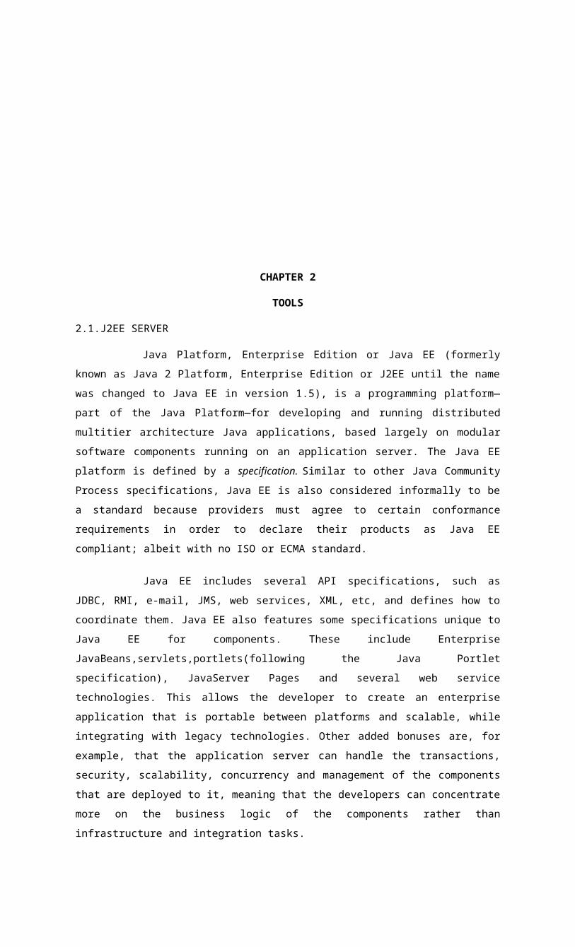
CHAPTER 2
TOOLS
2.1.J2EE SERVER
Java Platform, Enterprise Edition or Java EE (formerly known as Java 2 Platform,
Enterprise Edition or J2EE until the name was changed to Java EE in version 1.5), is a programming
platform—part of the Java Platform—for developing and running distributed multitier architecture
Java applications, based largely on modular software components running on an application server.
The Java EE platform is defined by a specification. Similar to other Java Community Process
specifications, Java EE is also considered informally to be a standard because providers must agree to
certain conformance requirements in order to declare their products as Java EE compliant; albeit with
no ISO or ECMA standard.
Java EE includes several API specifications, such as JDBC, RMI, e-mail, JMS, web
services, XML, etc, and defines how to coordinate them. Java EE also features some specifications
unique to Java EE for components. These include Enterprise JavaBeans,servlets,portlets(following the
Java Portlet specification), JavaServer Pages and several web service technologies. This allows the
developer to create an enterprise application that is portable between platforms and scalable, while
integrating with legacy technologies. Other added bonuses are, for example, that the application server
can handle the transactions, security, scalability, concurrency and management of the components that
are deployed to it, meaning that the developers can concentrate more on the business logic of the
components rather than infrastructure and integration tasks.
Java Platform, Enterprise Edition (Java EE) is the industry standard for developing
portable, robust, scalable and secure server-side Java applications. Building on the solid foundation of
the Java Platform, Standard Edition (Java SE), Java EE provides web services, component model,
management, and communications APIs that make it the industry

standard for implementing enterprise-class service-oriented architecture (SOA) and next-generation
web applications.
2.1.1 J2EE Sever And Prepared Statement
When the J2EE server gives your application a connection, it isn't giving you the
actual connection; you're getting a wrapper. You can verify this by looking at the name of the class for
the connection you are given. It won't be a database JDBC connection, it'll be a class created by your
application server. Normally, if you called close on a connection then the jdbc driver closes the
connection. We want the connection to be returned to the pool when close is called by a J2EE
application. We do this by making a proxy jdbc connection class that looks like a real connection. It
has a reference to the actual connection. When we invoke any method on the connection then the
proxy forwards the call to the real connection. But, when we call methods such as close instead of
calling close on the real connection, it simply returns the connection to the connection pool and then
marks the proxy connection as invalid so that if it is used again by the application we'll get an
exception.
Wrapping is very useful as it also helps J2EE application server implementers to add
support for prepared statements in a sensible way. When an application calls
Connection.prepareStatement, it is returned a PreparedStatement object by the driver. The application
then keeps the handle while it has the connection and closes it before it closes the connection when the
request finishes. However, after the connection is returned to the pool and later reused by the same, or
another application, , then ideally, we want the same PreparedStatement to be returned to the
application.
2.1.2.The advantages of J2EE
The J2EE framework today provides the standard platform for distributed
applications. It creates a standard in which application components can be distributed and reused.
The evolution of component frameworks has matured to provide significant benefits
for application development:
• Code reusability
• Simplification of the development process
• Faster maintenance due to smaller units of code
• Better performance through load-balancing and distribution of components
• Higher scalability of the application
Technically J2EE is not a language; it is a group of specifications, frameworks,
technologies, etc. for building distributed enterprise systems. J2EE is comprised of a number of
programming and scripting languages including Java, XML, JSP, HTML, SQL, and others. Some of
the advantages of J2EE include cross-platform portability, availability of open-source libraries, a huge
server-side deployment base..
EJBs have become today the widely accepted open standard for components. They
provide all the benefits described above and add the important concept of portability. There are
numerous providers of J2EE servers today, all conforming to open standards, thus enabling the
customer to freely choose the environment.
2.2 JAVA SERVER PAGE
Java Server technology consists of Java-based frameworks and APIs that together
provide a versatile combination, capable of building many kinds of server applications that are
portable and scalable.
Front-end servers::- The most visible portion of servers are the front-end Java
provides server APIs for the following:
Message exchanges Java Message Services (JMS) provides message queuing services
and can be used for message business-to-business (B2B) communication or communication between
applications (A2A or EAI) JMS provides both point-to-point and publish/subscribe asynchronous
message queuing.
Back-end servers::- built with Enterprise JavaBeans technology provide distributed
business and transaction processing. EJB provides containers for two types of Enterprise JavaBeans,
Session Beans and Entity Beans:
Session Beans provide control over interaction with users. Session Beans can be
"stateless" or "stateful" (such as for shopping carts).
Entity Beans represent persistent entities (such as accounts, product inventory) that
are stored in databases or in external applications.Entity Beans can be managed by the container in
what is called Container Managed Persistence (CMP), or by the bean itself in Bean Managed
Persistence (BMP). Both CMP and BMP can use Object Relational Mapping Tools to map beans to
database entitites.
Communication with EJB containers uses Java Naming and Directory Services (JNDI) plus
Remote Method Invocation (RMI), and possibly SOAP or JMS. J2EE-branded servers supply a
Deployment Tool that automates the configuration process between the front-end servers and EJB
containers and between containers.

2.2.1 Advantages Of JSP
• vs. Active Server Pages (ASP). ASP is a similar technology from Microsoft. The
advantages of JSP are twofold. First, the dynamic part is written in Java, not Visual Basic or
other MS-specific language, so it is more powerful and easier to use. Second, it is portable to
other operating systems and non-Microsoft Web servers.
• vs. Pure Servlets. JSP doesn't give you anything that you couldn't in principle do with
a servlet. But it is more convenient to write (and to modify!) regular HTML than to have a
zillion println statements that generate the HTML. Plus, by separating the look from the
content you can put different people on different tasks: your Web page design experts can
build the HTML, leaving places for your servlet programmers to insertthedynamic content.
• vs. Server-Side Includes (SSI). SSI is a widely-supported technology for including
externally-defined pieces into a static Web page. JSP is better because it lets you use servlets
instead of a separate program to generate that dynamic part. Besides, SSI is really only
intended for simple inclusions, not for "real" programs that use form data, make database
connections, and the like.
• vs. JavaScript. JavaScript can generate HTML dynamically on the client. This is a
useful capability, but only handles situations where the dynamic information is based on the
client's environment. With the exception of cookies, HTTP and form submission data is not
available to JavaScript.
• vs. Static HTML. Regular HTML, of course, cannot contain dynamic information. JSP is so easy
and convenient that it is quite feasible to augment HTML pages that only benefit marginally
by the insertion of small amounts of dynamic data. Previously, the cost of using dynamic data
would preclude its use in all but the most valuable instances.
2.3 CLOUDSCAPE DATABASE
A Cloudscape database contains dictionary objects such as tables, columns, indexes,
and jar files. A Cloudscape database can also store its own configuration information.
The Database Directory:- A Cloudscape database is stored in files that live in a
directory of the same name as the database. Database directories typically live in system directories.
Connecting to Databases:- You connect to a database using a form of the Cloudscape
connection URL as an argument to the DriverManager.getConnection call (see Cloudscape JDBC
Database Connection URL). You specify a path to the database within this connection URL.
2.3.1 Cloudscape Security Features

Because Cloudscape does not support traditional grant and revoke features, the
security model has some basic limitations. For both embedded and client/server systems, it assumes
that users are trusted. You must trust your full-access users not to perform undesirable actions. You
lock out non full-access users with database properties, which are stored in the database (and in an
encrypted database these properties are also encrypted).
Note, however, for a distributed/embedded system that a sophisticated user with the database
encryption key might be able to physically change those properties in the database files.
In addition, in the Cloudscape system, it is not necessary to have a specific connection
(or permission to access a particular database) to shut down the system. Any authenticated user can
shut down the system.
2.3.2 Value-Added Features
• Zero administration: IBM Cloudscape can be easily deployed by adding the core
database server with your Java application.
• Multiple platform compatibility: IBM Cloudscape fully supports Sun
Microsystems Java technology standards and runs on any standard JVM V1.3, or later.
It supports Java 2 and J2EE.
• Full-featured database in compact design: IBM Cloudscape is fine-tuned for
efficient use of resources and a high number of concurrent users. Other features
• Read-committed, read-uncommitted, serializable, and repeatable-read isolation
levels
• Row-level locking
• Optimal transaction performance
• Low memory overhead for connections
• Fast access time and space reclamation for long rows
• Cost-based optimizer that supports hash joins, sort avoidance,
• and row-level or tablelevel locking based on percent of data selected
• Fast query compilation
• Multiple user support
• Built-in performance diagnostics: query statistics, locks, and space usage
• Advanced security features
• Signed Java Archive (JAR) files
• LDAP or application-defined secure user authentication
CHAPTER 3
PROTOCOLS

3.1 INTRODUCTION
The Java Mail API has been used to implement notification services in J2EE
applications. Emails were an easy way to notify end-users of business events in an application. With
the emergence of new notification channels (such as WAP Phones, Instant Messaging applications,
and SMS Pagers), sending notifications has become more complicated. Now, applications have to
support an ever- changing set of communication channels that end users would like to be notified on.
Each of these channels has a separate API that must be used to communicate with it, so a considerable
amount of time will be needed by developers to code these API's into their applications. Additionally,
once developers have finished building the communication mechanisms, they will also need a way of
determining where to contact an end user at what time (i.e. should an email be sent to the users PC, or
should a SMS page be sent to the users cell phone, or both?).
3.2. SMTP
SMTP or Simple Mail Transfer Protocol is a way to transfer email reliably and
efficiently. SMTP is a relatively simple, text-based protocol, where one or more recipients of a
message are specified (and in most cases verified to exist) and then the message text is transferred.
You can think of SMTP as the language that mail servers use to communicate among themselves.
Since this protocol started out as purely ASCII text-based, it did not deal well with
binary files. When the user wants to send a message to someone, the sender-SMTP establishes a two-
way transmission channel to a receiver-SMTP. SMTP commands are generated by the sender-SMTP
and sent to the receiver-SMTP. SMTP replies are sent from the receiver-SMTP to the sender-SMTP in
response to the commands. In case a direct connection does not exist between the sender and the final
destination, the message may be sent via one or more relay SMTP-servers. The relay SMTP-servers
first act as receivers and then relays the message to the next SMTP. To be able to provide the relay
capability the
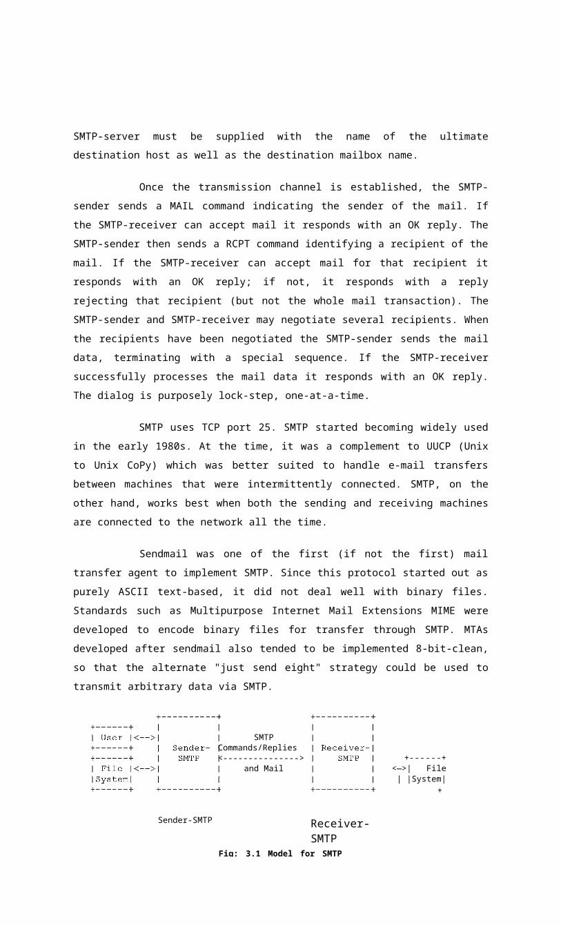
SMTP-server must be supplied with the name of the ultimate destination host as well as the
destination mailbox name.
Once the transmission channel is established, the SMTP-sender sends a MAIL
command indicating the sender of the mail. If the SMTP-receiver can accept mail it responds with an
OK reply. The SMTP-sender then sends a RCPT command identifying a recipient of the mail. If the
SMTP-receiver can accept mail for that recipient it responds with an OK reply; if not, it responds with
a reply rejecting that recipient (but not the whole mail transaction). The SMTP-sender and SMTP-
receiver may negotiate several recipients. When the recipients have been negotiated the SMTP-sender
sends the mail data, terminating with a special sequence. If the SMTP-receiver successfully processes
the mail data it responds with an OK reply. The dialog is purposely lock-step, one-at-a-time.
SMTP uses TCP port 25. SMTP started becoming widely used in the early 1980s. At
the time, it was a complement to UUCP (Unix to Unix CoPy) which was better suited to handle e-mail
transfers between machines that were intermittently connected. SMTP, on the other hand, works best
when both the sending and receiving machines are connected to the network all the time.
Sendmail was one of the first (if not the first) mail transfer agent to implement SMTP.
Since this protocol started out as purely ASCII text-based, it did not deal well with binary files.
Standards such as Multipurpose Internet Mail Extensions MIME were developed to encode binary
files for transfer through SMTP. MTAs developed after sendmail also tended to be implemented 8-bit-
clean, so that the alternate "just send eight" strategy could be used to transmit arbitrary data via
SMTP.
Receiver-SMTP
SMTPCommands/Replies<--------------->
and Mail+------+
<—>| File | |System|
+
Sender-SMTP
Fig: 3.1 Model for SMTP Use

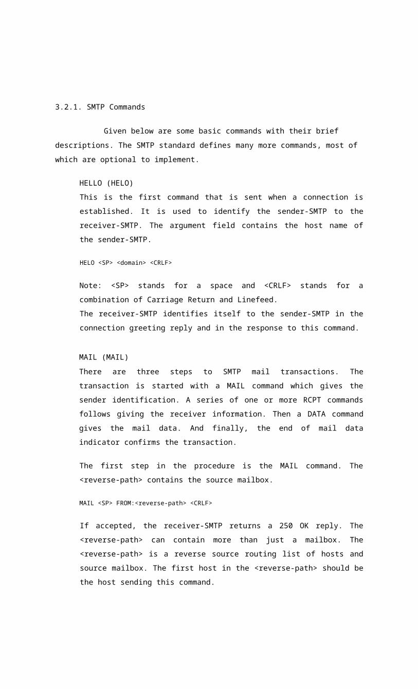
3.2.1. SMTP Commands
Given below are some basic commands with their brief descriptions. The SMTP
standard defines many more commands, most of which are optional to implement.
HELLO (HELO)
This is the first command that is sent when a connection is established. It is used to identify
the sender-SMTP to the receiver-SMTP. The argument field contains the host name of the
sender-SMTP.
HELO <SP> <domain> <CRLF>
Note: <SP> stands for a space and <CRLF> stands for a combination of Carriage Return and
Linefeed.
The receiver-SMTP identifies itself to the sender-SMTP in the connection greeting reply and
in the response to this command.
MAIL (MAIL)
There are three steps to SMTP mail transactions. The transaction is started with a MAIL
command which gives the sender identification. A series of one or more RCPT commands
follows giving the receiver information. Then a DATA command gives the mail data. And
finally, the end of mail data indicator confirms the transaction.
The first step in the procedure is the MAIL command. The <reverse-path> contains the source
mailbox.
MAIL <SP> FROM:<reverse-path> <CRLF>
If accepted, the receiver-SMTP returns a 250 OK reply. The <reverse-path> can contain more
than just a mailbox. The <reverse-path> is a reverse source routing list of hosts and source
mailbox. The first host in the <reverse-path> should be the host sending this command.
RECIPIENT (RCPT)
This command gives a forward-path identifying one recipient. If accepted, the receiver-SMTP returns
a 250 OK reply, and stores the forward-path. If the recipient is unknown the receiver-SMTP returns a
550 Failure reply. This second step of the procedure can be repeated any number of times.
RCPT <SP> TO:<forward-path> <CRLF>

The <forward-path> can contain more than just a mailbox. The <forward-path> is a source routing list
of hosts and the destination mailbox. The first host in the <forward-path> should be the host receiving
this command.
DATA (DATA)
The third step in the procedure is the DATA command.
DATA <CRLF>
If accepted, the receiver-SMTP returns a 354 Intermediate reply and considers all succeeding lines to
be the message text. When the end of text is received and stored the SMTP-receiver sends a 250 OK
reply.
Since the mail data is sent on the transmission channel the end of the mail data must be indicated so
that the command and reply dialog can be resumed. SMTP indicates the end of the mail data by
sending a line containing only a period.
The mail data includes the memo header items such as Date, Subject, To, Cc, From etc.
VERIFY (VRFY)
This command asks the receiver to confirm that the argument identifies a user. If it is a user name, the
full name of the user (if known) and the fully specified mailbox are returned.
VRFY <SP> <user name> <CRLF>
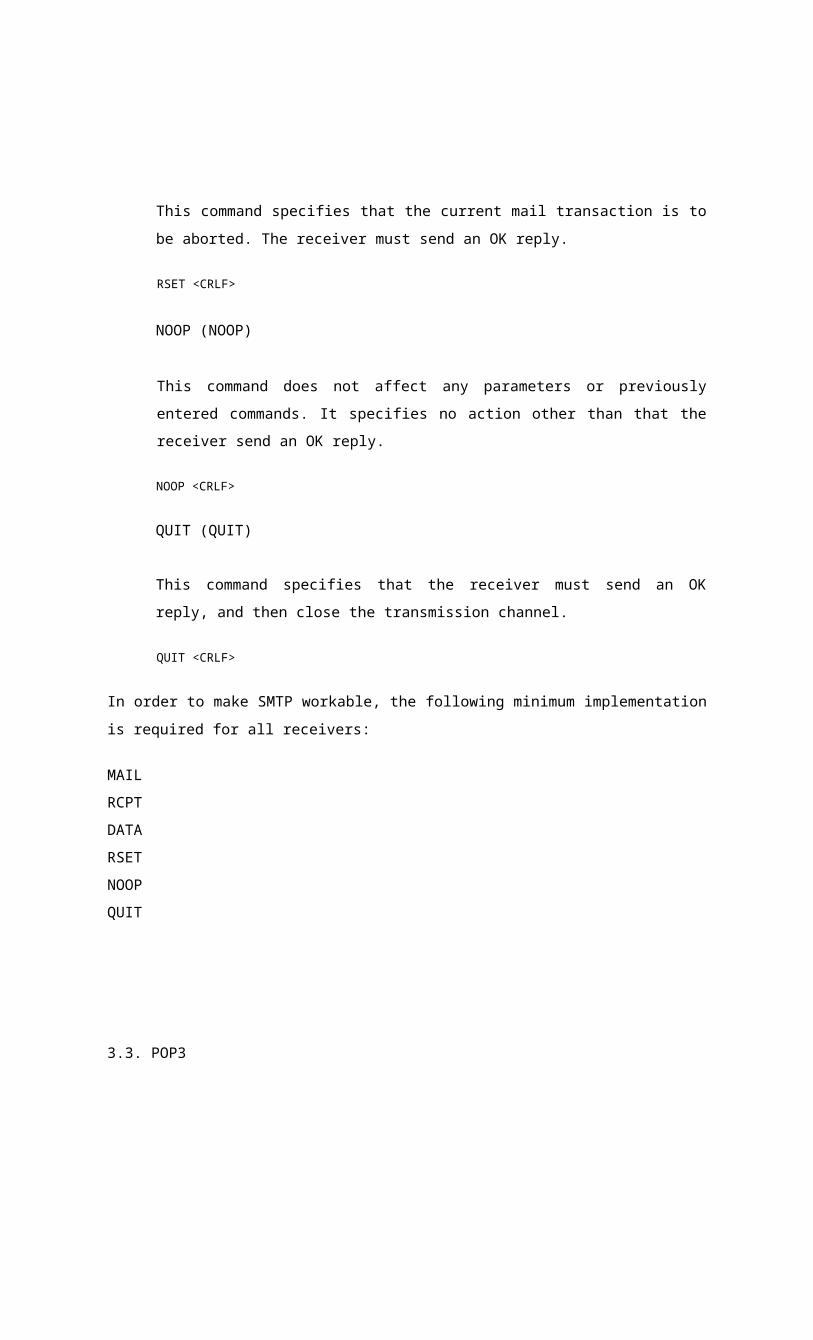
RESET (RSET)
This command specifies that the current mail transaction is to be aborted. The receiver must
send an OK reply.
RSET <CRLF>
NOOP (NOOP)
This command does not affect any parameters or previously entered commands. It specifies
no action other than that the receiver send an OK reply.
NOOP <CRLF>
QUIT (QUIT)
This command specifies that the receiver must send an OK reply, and then close the
transmission channel.
QUIT <CRLF>
In order to make SMTP workable, the following minimum implementation is required for all
receivers:
RCPT
DATA
RSET
NOOP
QUIT
3.3. POP3
Post Office Protocol, a protocol used to retrieve e-mail from a mail server. Most e-
mail applications (sometimes called an e-mail client) use the POP protocol, although some can use the
newer IMAP (Internet Message Access Protocol). There are two versions of POP. The first, called
POP2, became a standard in the mid-80's and requires SMTP to send messages. The newer version,
POP3, can be used with or without SMTP.
POP3 (Post Office Protocol 3) is the most recent version of a standard protocol for
receiving e-mail. POP3 is a client/server protocol in which e-mail is received and held for you by your
Internet server. Periodically, you (or your client e-mail receiver) check your mail-box on the server
and download any mail, probably using POP3. This standard protocol is built into most popular e-mail
products, such as Eudora and Outlook Express. It's also built into the Netscape and Microsoft Internet
Explorer browsers.
POP3 is designed to delete mail on the server as soon as the user has downloaded it.
However, some implementations allow users or an administrator to specify that mail be saved for
some period of time. POP can be thought of as a "store-and-forward" service. An alternative protocol
is Internet Message Access Protocol (IMAP). IMAP provides the user more capabilities for retaining
e-mail on the server and for organizing it in folders on the server. IMAP can be thought of as a remote
file server.
POP and IMAP deal with the receiving of e-mail and are not to be confused with the
Simple Mail Transfer Protocol (SMTP), a protocol for transferring e-mail across the Internet. You
send e-mail with SMTP and a mail handler receives it on your recipient's behalf. Then the mail is read
using POP or IMAP. .
4.1 INTRODUCTION
All projects are feasible when given unlimited resources and infinite time. It is both
necessary and prudent to evaluate the feasibility of a project at the earliest possible time. A feasible
study is not warranted for system in which economic justification is observed, technical risk is low,
few legal problems are expected and no reasonable alternative exists. An estimate is made of whether
CHAPTER 4
SYSTEM STUDY
Fig 3.2 Working of protocol

the identified user needs may be satisfied using our recent software and hardware technologies. The
study will decide if the proposed system will be cost effective, from the business point of view and it
can be developed in the existing budgetary constraints. The feasibility study should be relatively sharp
ad quick. The gesture should inform the decision of whether to go ahead with a more detailed
analysis.
Feasibility study may be documented as a separated report to higher officials of the
top-level management and can be included as appendices to the system specification. Feasibility and
risk analysis is detailed in many worries. If there is more project risk then the feasibility of producing
the quality software is reduced. The study is done in two phases
> Operational Feasibility
> Technical Feasibility
4.1.1 Operational Feasibility
In the proposed System named V3mailserver the operational feasibility study is
performed with the help of the users of the system and the management. The first challenge was
whether the system meets the organizational requirement. This is checked by the system requirement
collected from the users and the management and the operational feasibility proved that the system is
capable to meet its functional requirements.
During the operational feasibility study the proposed system, is checked whether it
can run with universal standards.
All the business methods implemented in the system is selected according to increase
the user acceptance. There was no difficulty in implemented the software and proposed system is so
effective, user friendly, functionally reliable so that the users in the company will find that the new
system reduces the hard steps.
4.1.2 Technical Feasibility
In the proposed system named V3mailserver the technical feasibility study is
conducted by considering the risk related to developing the system, the resources available to develop
the system and the availability of the technology to develop the system. The development risk
considered the factors like whether the system can implement using existing technology and the
design of the system can run on the real environment. The resource availability checks the availability
of resources like time, human, hardware etc. The technology using to implement the system is
selected according to the technical feasibility study. The technical feasibility study on the technology
found that it can implement all the functional requirements of the proposed system. The technology
selected according to accept the system globally and the development of the system according to the
universal standards.
Technical feasibility study of V3mailserver covered the hardware as well as the
software requirements. The scope was whether the work for the project is done with the current
equipments and the existing software technology has to be examined in the feasibility study. The
outcome was found to be positive.
CHAPTER 5
SYSTEM ANALYSIS
Requirement analysis can be defined as a detailed study of various operations
performed by a system and their relationship within and outside of the system. One aspect of the
analysis is designing the boundaries of the system and determining whether or not a candidate system
should other related systems. During analysis data are collected on the available files, decision points
and transactions handled by the present system. The common tools used in the analysis phase are Data
Flow Diagram, interviews and on site observations.
We can say Analysis as the process of taking known facts concerning a system,
breaking these into their elements and establishing logical relationships between the laments, with
objective of producing a specification of requirements. Analysis can be done in a disciplined way,
using appropriate tools in all stages of the project. During fact-finding, the use of standard forms will
help to ensure that nothing conflicts or is omitted. The tool of analysis consists of lists, structure
charts, grid charts and flow charts. The steps in the analysis are:
• Defining system objectives and results.
• Trace back to the actions required for the achievement of objectives and results.
• Carry out instructions, which prompt the achievement of objectives and must be analyzed In
relation to the decisions, which produce them.
• Confirm the notifications that have been carried out.
• The information based on the decisions can be analyzed into the data and procedures required
to produce it.
At each step it is necessary to:

• Identify the relevant facts, and establish the relationship between them.
• Compare that set of facts with the sets at each adjoining steps and establish the relationship
between the facts in these sets.
CHAPTER 6
SYSTEM DESIGN
6.1 FUNDAMENTAL DESIGN CONCEPTS
A set of fundamental design concepts are evolved over the past decades, although the
degree of interest in each concept has varied over the years, each has stood the test of time. Each one
provides the software designer with a foundation from which more sophisticated design methods can
be applied. Fundamental design concepts provide the necessary frame work for "getting it right".
6.2 MODULARITY
Modularity is the single attribute software that allows a program to be intellectually
manageable. Software architecture embodies modularity, that is , software is divided into named and
addressable component called modules that are integrated to satisfy problem requirements. We have
divided our project into four modules. Administrator, Inbox, My settings and Protocol.
6.3 DATA STRUCTURE
Data structure is a representation of logical relationship among individual elements of
data. Because the structure of information will invariably affect the final procedural design, data
structure is very important as the program structure to the representation of the software architecture.
Data structure dictates the organization, methods of access, degree of associatively, and processing
alternatives for information. The organization and complexity of a data structure are limited only by
ingenuity of the designer. Scalar item array and Array list and Vectors are some of the representations
of the data structure used in our project.
CHAPTER 7
DATABASE DESIGN
The overall objective in the development of database technology has been to treat data
as an organizational resource and as an integrated whole. DBMS allow data to be protected and
organized separately from other resources. Database is an integrated collection of data. The most
significant form of data as seen by the programmers is data as stored on the direct access storage
devices. This is the difference between logical and physical data.
Database files are the key source of information into the system. It is the process of
designing database files, which are the key source of information to the system. The files should be
properly designed and planned for collection, accumulation, editing and retrieving the required
information.
The organization of data in database aims to achieve three major objectives:-
• Data integration.
• Data integrity.
• Data independence.
The proposed system stores the information relevant for processing in the MS SQL
SERVER database. This database contains tables, where each table corresponds to one particular type
of information. Each piece of information in table is called a field or column. A table also contains
records, which is a set of fields. All records in a table have the same set of fields with different
information. There are primary key fields that uniquely identify a record in a table. There are also
fields that contain primary key from another table called foreign keys.
7.1 NORMALIZATION
Normalization is a technique of separating redundant fields and braking up a large
table in to a smaller one. It is also used to avoid insertion, deletion and updating anomalies. All the
tables have been normalized up to the third normal form. In short the rules for each of the three
normal forms are as below.
First Normal Form
A relation is said to be in 1NF if all the underlying domain of attributes contain
simple individual values.
Second Normal Form
The 2NF is based on the concept of full functional dependency. A relation said to be
in 2NF if and only if it is in 1NF and every non-key attribute is fully functionally dependent on
candidate key of the table.
Third Normal Form
The 3NF is based on the concept of transitive dependency. A relation in 2NF is said
to be in 3NF if every non-key attribute is non-transitively.
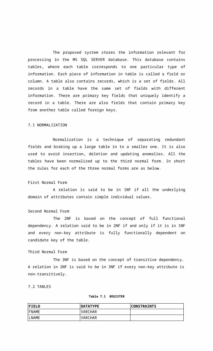
7.2 TABLES
Table 7.1 REGISTER
FIELD DATATYPE CONSTRAINTSFNAME VARCHARLNAME VARCHARGENDER VARCHARMAHLHD VARCHAR PRIMARY KEYPASSWD VARCHARSQUES VARCHARANS VARCHARBDAY VARCHAROCCUPATION VARCHAREDUCATION VARCHARZIP VARCHARALTID VARCHARMOBILE VARCHARROLL VARCHAR
The above table stores the details of registered user such as user name, password, etc.
The entries in the table all inserted during the new user registration process.OFFPHONE VARCHARMOB VARCHARADDRESS VARCHARBDAY VARCHARMAILID VARCHAR
The above table stores the details of friends such as user name, mailid, etc. The entries in the
table all inserted during adding friends to addressbook.
Table 7.3 INBOX
FIELDDATATYPECONSTRAINTSFNAMEVARCHARMNAMEVARCHARLNAMEVARCHARNNAMEVARCHARPRIMARY KEYEMAILVARCHARALTIDVARCHARHPHONEVARCHAR
Table 7.2 ADDRESSBOOK
FIELD DATATYPE CONSTRAINTSMSGID LONGINT PRIMARY KEYSENDER VARCHARSUBJECT VARCHARDAT VARCHARMSG VARCHARSIZ VARCHARMAILID VARCHARSTATUS INT
The above table stores the details of message such as message id, sender, data etc. The entries
in the table all inserted during the retrieving of mails
The above table stores the details of mail such as message id, sender, data, etc. The entries in
the table all inserted when user move mail to myfolder
Table 7.5 SENT FOLDER
FIELD DATATYPE PRIMARY KEYMSGID LONGINTMAILID VARCHARSENDER VARCHARSUBJECT VARCHARDAT VARCHARMSG VARCHARSTATUS I NT
The above table stores the details of mail such as message id, sender, data, etc. The entries in
the table are inserted when user send mails.
FIELDDATATYPECONSTRAINTSMSGIDLONGINTPRIMARY KEYSENDERVARCHARSUBJECTVARCHARDATVARCHARMSGVARCHARSIZVARCHARMAILIDVARCHAR
Table 7.4 MYFOLDER

Table 7.6 SIGNATURE
FIELD DATATYPE CONSTRAINTSSIGNID INT PRIMARY KEYSIGNATURE VARCHARMAILID VARCHAR
The above table stores the details of signature of the user. The entries in the table all
inserted when user add signature
The above table stores the details of mails deleted from inbox such as message id,
sender, data, etc. The entries in the table all inserted when user delete mail.
7.3 DATA FLOW DIAGRAMS
Data Flow Diagram is the graphical description of the system's data and how the
processes transform the data. Data Flow diagram depicts information flow, the information flow and
the transforms that are applied as data move from the input to output. It is the starting point of the
design phase that functionally decomposes the requirement specifications down to the lowest level of
details. Thus a DFD describes what data flows (logical) rather than how they are processed.
Unlike detailed flowchart, Data Flow Diagrams do no supply detailed description of
the modules but graphically describes a system's data and how the data interacts with the system. To
construct a Data Flow Diagram, we use
> Arrows
> Circles
> Open End Box
> Squares
An arrow identifies the dataflow in motion. It is a pipeline through which information is flown like the
rectangle in the flowchart. A circle stands for process that
FIELDDATATYPECONSTRAINTSMSGIDLONGINTPRIMARY KEYSENDERVARCHARSUBJECTVARCHARDATVARCHARMSGVARCHARSIZVARCHARMAHLHDVARCHAR
Table 7.7 TRASH
converts data into information. An open-ended box represents a data store, data at rest or a temporary
repository of data. A square defines a source or destination of system data.
Rules for constructing a Data Flow Diagram
> Arrows should not cross each other.
> Squares, circles and files must bear names.
> Decomposed data flow squares and circles can have same names.
> Choose meaningful names for data flow
> Draw all data flows around the outside of the diagram.
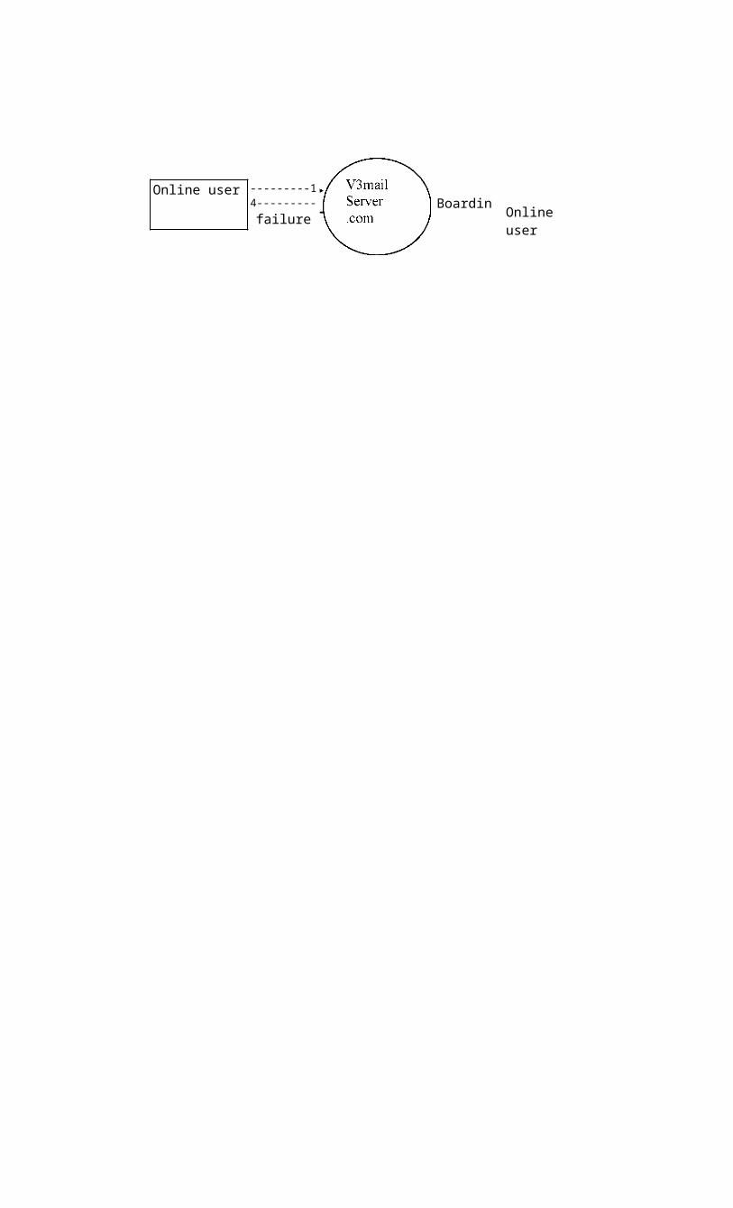
Online user ---------14---------
failure Online userBoarding
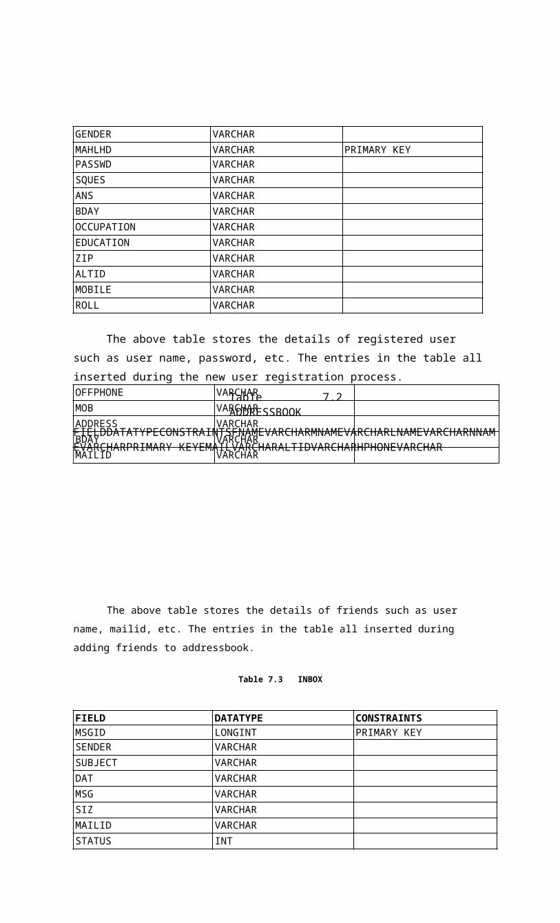
Fig:7.1 Level 0 DFD
Mail id,secQ Registeranswer <----------
password
Fig:7.2 Level 1 DFD

O n l i n e u ser User ,Details

Fig:7.3 Level 2 DFD
delete
username password
Online user

Fig:7.4 Level 3 DFD
CHAPTER 8
CODING
The goal of coding phase is to translate the design of the system in to code in a given
programming language. For a given design, the aim in this phase is to implement the design in the best
possible manner. Well-written code can reduce the resting and maintenance effort. During coding, the
focus should on developing programs that are easy to read and understand and not simply on developing
programs that are easy to write. Simplicity and clarity should be strived for during the code phase.
An important concept that helps the understandability of programs is structured
programming. The program that should be organized as a sequence of statements
and during execution the statements are executed in the sequence given in the program. There are
many different criteria for judging of the program, execution time and required memory.

CHAPTER 9
SYSTEM IMPLEMENTATION
Implementation includes all those activities that take place to convert from the old
system to the new. The old system consists of manual operations, which is operated in a very
different manner from the proposed new system. A proper implementation is essential to provide
a reliable system to meet the requirements of the organizations. An improper installation may
affect the success of the computerized system.
9.1 IMPLEMENTATION METHODS
There are several methods for handling the implementation and the consequent
conversion from the old to the new computerized system.
The most secure method for conversion from the old system to the new system is
to run the old and new system in parallel. In this approach, a person may operate in the manual
older processing system as well as start operating the new computerized system. This method
offers high security, because even if there is a flaw in the computerized system, we can depend
upon the manual system. However, the cost for maintaining two systems in parallel is very high.
This outweighs its benefits.
Another commonly method is a direct cut over from the existing manual system
to the computerized system. The change may be with in a week or with in a day. There are no
parallel activities. However, there is no remedy in case of a problem. This strategy requires
careful planning. A working version of the system can also be implemented in one part of the
organization and the personnel will be piloting the system and changes can be made as and
when required. But this method is less preferable due to the loss of entirety of the system.
9.2 IMPLEMENTATION PLAN
The implementation plan includes a description of all the activities that must occur to
implement the new system and to put it into operation. It identifies the personnel responsible for the
activities and prepares a time chart for implementing the system.

The implementation plan consists of the following steps. o
List all files required for implementation.
o Identify all data required to build new files during the implementation. o
List all new documents and procedures that go into the new system.
The implementation plan should anticipate possible problems and must be able to
deal with them. The usual problems may be missing documents; mixed data formats between current
and files, errors in data translation, missing data etc.

CHAPTER 10
SYSTEM TESTING
Testing is the major quality measure employed during software development. After
the coding phase, computer programs are available that can be executed for testing purposes. Testing
not only has to uncover errors introduced during coding, but also locates errors committed during the
previous phases. Thus the aim of testing is to uncover requirements, design or coding errors in the
program.
10.1 TYPES OF TESTING
This is the phase where bug in the program was to be found and corrected. One of the
goals during dynamic testing is to produce a test suite. This is applied to ensure that the modification
of the program does not have any side effects. This type of testing is called regression testing. Testing
generally removes all the residual bugs and improves the reliability of the program. The basic testing
types are
> Unit testing
> Integration testing
> Validation testing
> Output testing
> User acceptance testing
10.1.1 Unit Testing
This is the first level of testing. In this different modules are tested against the
specifications produced during the design of the modules. Unit testing is done for the verification of
the code produced during the coding of the single module in an isolated environment. Unit testing first
focuses on the modules independently of one another to locate errors.

After coding, each dialogue is tested and run individually. All unnecessary coding
were removed and it was ensured that all the modules worked, as the programmer would expect.
Logical errors found were corrected.
So, by working all the modules independently and verifying the outputs of each module in the
presence of staff was conducted that the program was functioning as expected.
10.1.2 Integration Testing
Data can be lost access an interface, one module can have as adverse effect on another
sub-functions when combined, may not produce the desired major functions. Integration testing is a
systematic testing for constructing the program structure, while at the same time conducting test to
uncover errors associated within the interface. The objectives are to take unit tested as a whole. Here
correction is difficult because the vast expenses of the entire program complicate the isolation of
causes. Thus in the integration testing step, all the errors uncovered are corrected for the next testing
stages.
10.1.3 Validation Testing
This provides the final assurance that the software meets all the functional, behavioral
and performance requirements. The software is completely assembled as a package. Validation
succeeds when the software functions in a manner in which the user expects. Validation refers to the
process of using software in a live environment in order to find errors. During the course of validating
the system, failures may occur and sometimes the coding has to be changed according to the
environment.
Once the application was free all the logical and interface errors, inputting dummy
data ensured that the software developed satisfied all the requirements of the user.
10.1.4 Output Testing
After performing the validation testing, the next step is the output testing of the
proposed system since no system could be useful if it does not produces the required output generated
or considered into two ways; one is on screen and another is printed format.
The output format on the screen is found to be correct as the format was designed in
the system design phase according to the user needs.
For the hard copy also the output comes out as the specified requirements by the user. Hence output
testing does not result in any correction in the system.
10.1.5 User Acceptance Testing
User acceptance of a system is the key factor for the success of any system. The
system under consideration is tested for user acceptance by constantly keeping in touch with the
prospective system users at the time of developing and making changes whenever required.
Preparation of test data plays a vital role in the system testing. After preparing g the
test data the system under study is tested using the test data. While testing the system by using the test
data, errors are again uncovered and corrected and the corrections are also noted for the future.
CHAPTER 11
SYSTEM SPECIFICATION
11.1 HARDWARE REQUIREMENTS
Client machine:Processor : Intel Pentium I or higher.Monitor : Min 14" color monitorRAM : 64 MBHard Disk : 40 GBKeyboard : Standard 104 keysModem : 56 KBPSMouse : Serial mouse.NIC : 10/100 Ethernet LAN
Server Machine
Processor : Intel Pentium IV or higher with minimum 1 GHz Speed.
Monitor : Min 14" color monitor
RAM : 1 GB
Hard Disk : 40 GB (Or higher for Code backup)
Keyboard : Standard 104 keys
Modem : 56 KBPS
Mouse : Serial mouse
NIC : 10/100 Ethernet LAN
11.2 SOFTWARE REQUIREMENTS
Client's Machine
Operating system : Windows, Linux
Browser : Internet Explorer 5.5 or any http Browser
Internet connection with a valid internet service provider
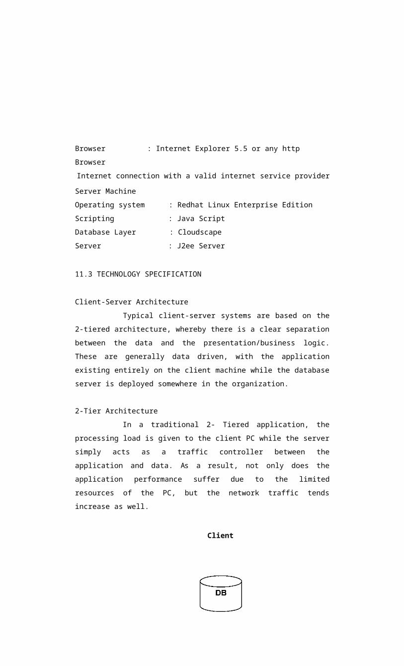
Server Machine
Operating system : Redhat Linux Enterprise Edition
Scripting : Java Script
Database Layer : Cloudscape
Server : J2ee Server

11.3 TECHNOLOGY SPECIFICATION
Client-Server Architecture
Typical client-server systems are based on the 2-tiered architecture,
whereby there is a clear separation between the data and the presentation/business
logic. These are generally data driven, with the application existing entirely on the
client machine while the database server is deployed somewhere in the organization.
2-Tier Architecture
In a traditional 2- Tiered application, the processing load is given to
the client PC while the server simply acts as a traffic controller between the application
and data. As a result, not only does the application performance suffer due to the
limited resources of the PC, but the network traffic tends increase as well.
Client
Fig 11.1: 2 Tier Architecture
3 - Tier Architecture
In 3- Tier architecture an application is broken into three separate
logical layers, each with a well - defined set of interfaces. The first tier is referred to as
the presentation layer and typically consists of graphical user interface of some kind.

The middle tier, or business layer, consists of application or business layer and the third layer- the
data layer contains the data that is needed for the application. The middle tier is basically the code that
the user calls upon to retrieve the desired data. The presentation layer then receives the data and
formats it for display. This separation of application logic from the user interface adds enormous
flexibility to the design of application. The third tier contains the data that is needed for the
application.
n- Tier Architecture
In an n - tier architecture the application logic is divided by function rather than
physically. N - Tier architecture then breaks down like this:
> A user interface that handle the user's interaction with the application; this can be web
browser running through a firewall, a heavier desktop application or even a wireless device
> Presentation logic that defines what the user interface displays and how a user's requests are
handled- depending on what user interfaces are supported we need to have slightly different
versions of the presentation logic to handle the client appropriately.
> Business logic that models the application's business rules, often through the interaction with
the application's data.
> Interface services that provide additional functionality required by the application
components, such as messaging, transactional support etc.
> The Data layer where the enterprise's data resides.

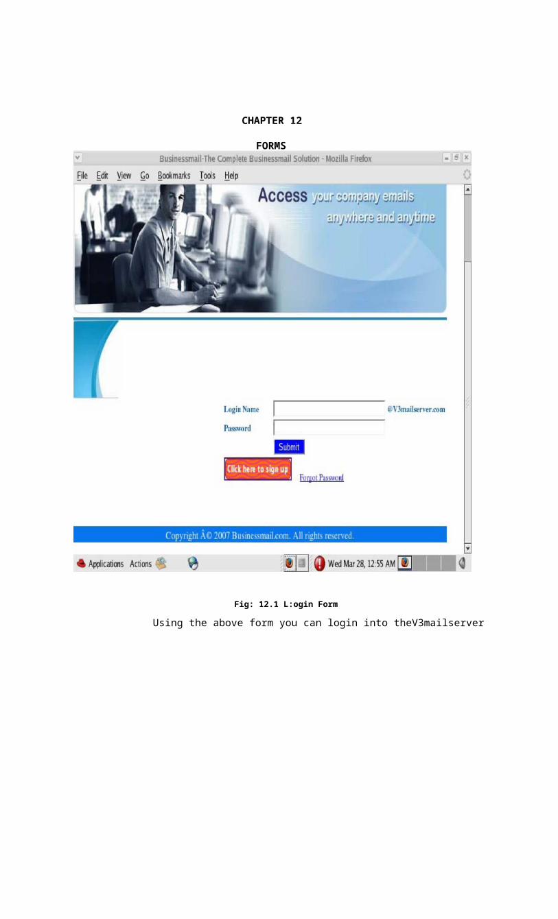
Fig: 12.1 L:ogin Form
Using the above form you can login into theV3mailserver
CHAPTER 12
FORMS

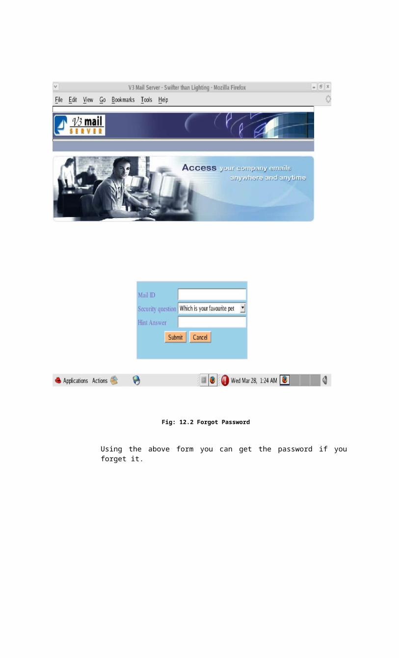
Fig: 12.2 Forgot Password
Using the above form you can get the password if you forget it.

Fig: 12.3 Registration Form
Using the above form you can register to the V3mailserver.

Using the above form you can see your mails in the V3mailserver
Fig:12.4 Inbox
Using the above form you can add and view your contacts from the V3mailserver.
Fig: 12.5 Address Book Form

Using the above form you can compose mail.
Fig: 12.6 Compose Form

Using the above form you can add signature and change your password.
Fig:12.7 Mysettings Form
CHAPTER 13
CONCLUSION
The project report entitled "V3 MAILSERVER" has come to its final stage.
The system has been developed with much care that it is free of errors and at the same time it is
efficient and less time consuming. The important thing is that the system is robust. Also provision is
provided for future developments in the system. The entire system is secured. This online system will
be approved and implemented soon.
RESUME
The developed system is flexible and changes can be made easily. The system is
developed with an insight into the necessary modification that may be required in the future. Hence the
system can be maintained successfully without much rework.
Our future plan is to provide an option to attach files. V3MAILSERVER can also
be improved by providing mobile alerts and chatting facility.
In our project we also plan to add AJAX. Ajax (also known as AJAX), shorthand
for "Asynchronous JavaScript and XML", is a web development technique for creating interactive web
applications. The intent is to make web pages feel more responsive by exchanging small amounts of
data with the server behind the scenes, so that the entire web page does not have to be reloaded each
time the user requests a change. This is meant to increase the web page's interactivity, speed, and
usability.
REFERENCES
1. Roger.S.Pressman (2005)'Software Engineering: A Practitioner's Approach',
McGraw Hill Professional, Fifth Edition. 2. Herbert Schildt (2002) Java 2: The Complete
Reference, Fifth Edition;
Tata McGraw Hill.
3 www.magicwinmail.net
4. http://java.sun.com .
5. www.infoworld.com