
UzarowskiL-How to Deal Under Budget Constraints …...How to Deal Under Budget Constraints with...
16
How to Deal Under Budget Constraints with Pavements on Melting Permafrost at Northern Airports Ludomir Uzarowski, Senior Pavement and Materials Engineer, Golder Associates Ltd. Bill Morrison, Manager Technical Services and Pavements, Government of Northwest Territories Rabiah Rizvi, Pavement and Materials Engineer, Golder Associates Ltd. Paper prepared for presentation at the Sustainability and Climate Change Considerations in Pavements Session of the 2016 Conference of the Transportation Association of Canada Toronto, ON
Transcript of UzarowskiL-How to Deal Under Budget Constraints …...How to Deal Under Budget Constraints with...

How to Deal Under Budget Constraints with Pavements on Melting Permafrost at Northern Airports
Ludomir Uzarowski, Senior Pavement and Materials Engineer, Golder Associates Ltd. Bill Morrison, Manager Technical Services and Pavements, Government of Northwest
Territories Rabiah Rizvi, Pavement and Materials Engineer, Golder Associates Ltd.
Paper prepared for presentation at the Sustainability and Climate Change Considerations in Pavements Session
of the 2016 Conference of the Transportation Association of Canada
Toronto, ON
2
ABSTRACT
Numerous airports pavements built in the North 50 or 60 years ago were constructed on permafrost. When the active layer that thaws and freezes again under the pavement was relatively shallow, the permafrost provided good support and the pavements performed well. However, due to climate change/global warming, the depth of the active layer became larger and the permafrost started to melt.
The airport in Yellowknife is located in a discontinuous permafrost zone. The asphalt pavement on Runway 10-28 was built in the 50s. The pavement includes 175 mm of asphalt and 0.6 m of granular materials. Soils are variable but typically include silts that are very frost susceptible. The soil is particularly poor at the location of an old water course. The surface drainage consists of two ditches at a significant distance from the runway and there are no subdrains. The permafrost is melting and the depth of the active layer is increasing. This in turn causes settlements and bumps in the pavement at a number of locations. At the same time, since the soils are frost susceptible, there are also frost heaves.
The airport in Hay River is located in a scattered discontinuous permafrost zone. The asphalt pavement on Runway 14-32 was built in 1966. It consists of 150 mm of asphalt and 1.1 m of granular materials. Similar to the Yellowknife Airport, the subgrade soils are frost susceptible. There are subdrains along both edges of the runway pavement; however, the subdrains have failed and the pavement over them has cracked severely. The investigation showed that the permafrost has almost melted. There are locations where the pavement has settled and bumps have formed. These locations are primarily in the non-keel zones, outside quarter of the pavement width immediately adjacent to the pavement edge.
The previous pavement rehabilitation designs by others included full or partial depth reconstruction and installation of thermal insulation. Unfortunately, both these alternatives are cost prohibitive. Construction costs in the North are very high compared to other areas of Canada and there are significant budgetary constraints. There is also concern about the long term performance of thermal insulation within the pavement structure.
The new pavement design recommendations were based on the assumption that the permafrost is melted or may come and go in the future. The pavements were designed similar to the ones located in non-permafrost zones, where significant frost heaving and spring seasonal thawing occurs. Emphasis was placed on drainage, surface and subsurface where necessary.

3
1.0 INTRODUCTION
Numerous airports in the northern latitudes of Canada were constructed approximately 50 to 60 years ago. At the time of construction of the pavement at these airport, depth of the seasonally frozen soils (active layer) was relatively shallow, and underlying the active layer were soils that were permanently frozen (permafrost). When these pavements were initially designed it was assumed that the subgrade soils would have significantly higher bearing capacities due to the presence of permafrost, as compared to the same soil types when not frozen. However, over the life of these pavements the thickness of the active layer has increased drastically and in some locations the permafrost has completely melted. The melting of the permafrost layers has in turn resulted in the reduction of the bearing capacity of the subgrade soils and a reduction in the design life of the pavement. These pavement are requiring significantly more maintenance and earlier than anticipated pavement rehabilitation.
In addition to the challenging ground conditions in the area of these airports, the cost for construction in these areas is also significantly greater than equivalent construction in southern latitudes. These airports are typically located in remote areas and the number of qualified contractors undertaking construction projects in very limited. Additionally, the quantity and variety of suitable materials for construction are also limited, and therefore the cost for construction tends to be very high.
Difficult ground conditions and high construction costs require that customized and unique approaches be taken for the design of the rehabilitation of the pavements at these airports. During pavement rehabilitation design it needs to be ensured that the reliability of pavement performance is not compromised and that the safety of the travelling public is considered to be paramount.
This paper discusses the two case studies of pavement rehabilitations that were recommended at Yellow Knife Airport and Hay River Airport, located in the Northwest Territories. The case studies will highlight the challenges that can be faced at airports at northern latitudes and the unique approaches that need to be taken in order to address these challenges, while not compromising the technical viability of the pavement rehabilitation strategy and the safety of the travelling public.
2.0 YELLOWKNIFE AIRPORT
The Government of Northwest Territories (GNWT) was concerned with roughness at localized areas on Runway 10-28. Golder was retained by the GNWT to carry out an assessment of the pertinent geotechnical conditions affecting surface stability in the study area and to provide feasible conceptual designs to improve permanent performance. Golder was provided with a number of different documents for our review. Additionally, Golder’s Senior Pavement and Materials Engineer also carried out a site visit to undertake a visual condition inspection of the existing pavement on Runway 10-28.
2.1 Pavement Visual Condition Inspection
The main objective of the visual condition inspection was to determine the type, severity and extent of the observed pavement distresses, and if possible to determine the possible causes of the distresses. In addition, pavement drainage conditions were also noted.
The following distresses were observed during the inspection:

4
Medium to high severity depressions/settlements and frost heaves at localized areas;
Low severity patching;
Throughout low to high severity longitudinal, transverse and diagonal cracking; and
Localized low to medium severity ravelling.
The medium to high severity depressions/settlements of the pavement on Runway 10-28 were the main concern since they are the primary cause of the pavement bumpiness or roughness. Although they were visibly of higher severity in the non-keel zone, as shown in Figures 1 to 3, several bumps extended across the entire runway pavement width. Figures 1 and 2 also clearly show that at some of the bump locations in the pavement there is also a corresponding depression in the shoulder.
The longitudinal profiles provided by GNWT showed significant bumps and the Boeing roughness index analysis showed a few locations that required intervention.
2.2 Pavement Structure and Ground Conditions
The runway is 1,524 m long and 46 m wide. The pavement structure on Runway 10-28 consists of the following:
175 mm of Hot Mix Asphalt (HMA);
150 mm of crushed gravel based; and
450 mm of subbase.
The condition of the pavement in terms of Pavement Condition Index (PCI) has significantly deteriorated between 2006 and 2015. However, since the PCI does not accurately reflect the roughness of the pavement, a different approach was used during this project. The main concern with the pavement on Runway 10-28 was the bumpiness and its impact on aircraft movements. For the purpose of this project, the total length of the runway pavement was divided into five sections from A to E based on pavement structure and condition. The pavement structure on the runway was generally underlain by a highly frost susceptible subgrade soil, ranging from sandy silt, to silt, to silty clay.
The depth to bedrock was determined using Ground Penetrating Radar. The bedrock is at shallow to medium depth in Sections A, B, C and E and on generally much deeper in Section D. It was concluded that this indicates that Section D is likely where an old watercourse existed and the soils there are likely the later sediments and fill materials. These materials are not only ice-rich and prone to permafrost thaw settlements but also are frost susceptible and prone to differential frost heaving in the presence of water.
2.3 Permafrost Condition
Yellowknife is located in a discontinuous permafrost zone. The freezing and thawing indices are 3,431 °C-days and 1,706 °C-days, respectively. Data from three thermistors installed beneath the runway pavement structure, shows that the temperature at the depth of the installed thermistors is at slightly above or very slightly below 0°C. With the warming trend of the annual air temperature

5
in Yellowknife, it is likely that the temperature of the soil may become even higher in the future. Our initial analysis indicated that due to excessive thawing the depth of the active layer in the permafrost is drastically increasing.
Since Yellowknife is located in a discontinuous permafrost zone, the soil may refreeze after a few cold winters or an exceptionally cold winter but it can also melt after a warm winter. Therefore, pavement designs based on the assumption of the presence of permafrost cannot be considered as reliable. Therefore, the pavement design should be based on the assumption of a reduced subgrade strength, i.e. design the pavement structure to have enough load carrying capacity during the frost thawing period.
2.4 Drainage Conditions
It was noticed during the May 2015 site visit that the drainage conditions of Runway 10-28 at Yellowknife Airport are very poor. Surface drainage is provided by a system of ditches and there is no subsurface drainage system. The entire airport location has a relatively flat grade with poor drainage capabilities. The situation is made more complicated by the fact that a section of Runway 10-28 was likely constructed over an old watercourse and blocked the previous natural drainage system.
The existing ditches are very shallow and overgrown with vegetation. Ponding water was observed near the intersection of Runways 10-28 and 15-33. Another serious concern about the drainage of Runway 10-28 is the condition of the shoulders. There are numerous depressions in the shoulders on both sides of the pavement, likely due to soil settlement caused by thawed permafrost. This results in water ponding near the edge of the pavement and saturating the pavement instead of flowing to the ditches. Saturated soils speed up permafrost melting. Also, the silty clays and silts under the pavement are frost susceptible and in the presence of water the pavement heaves in the winter. During the spring thaw when the ice melts the soils and granular materials are saturated and weak which results in further deformation of the pavement.
2.5 Pavement Roughness
It was observed during the May 2015 visit that the pavement on Runway 10-28 is bumpy, particularly along two sections of the runway. Those locations were previously identified by GNWT as being problematic. GNWT carried out Boeing roughness analysis using the LIDAR survey data. There were locations with excessive bumps. Figures 4 shows the recycle section on the runway.
Pavement roughness or bumpiness on Runway 10-28 is due to three main causes:
1. Pavement settlements/depressions due to melting permafrost and reduced soil support capacities;
2. Pavement deformations during spring thaw when the granular materials in the pavement are saturated with water that cannot drain through the underlying frozen material; and
3. Pavement frost heaving due to the presence of frost susceptible soil and access to water due
to the shallow water table and lack of surface and subsurface drainage.
Clear signs of all three causes were observed during the May 2015 site visit.

6
2.6 Pavement Repairs
Typically, the methods used to address permafrost and spring thaw weakening are as follows [1, 2, 3, 4, and 5]:
1. Providing complete frost protection by installing non-frost susceptible material to the depth of seasonal thaw. Normally, economic and practical considerations control the limit of the depth of treatment to a maximum of 1.8 m (6 feet). This method also addresses the potential for future frost heaving and improves the structural support for the pavement;
2. Accept a reduced subgrade strength where the pavement structure should have a sufficient support capacity during the seasonal permafrost thaw period. If this method is used, differential frost heaving should still be anticipated; and
3. Installing insulating panels – the panels are placed beneath the pavement structure to protect
against further degradation of permafrost. This method may lead to some problems and should be carefully considered on a site specific basis and some pavement engineers are skeptical about its application. This approach is also very expensive.
For this project the repair strategies included emergency repairs needed to address severe pavement bumps, pavement structural repairs and drainage improvements that are considered to be a critical step in pavement performance improvement.
The emergency repairs strategy to address the severe bumps included: limiting turbo jet aircraft traffic until the repairs are undertaken, repairing the bumps in the keel zone first by milling and overlaying with new asphalt; and followed by repairing the bumps in the non-keel zone.
In terms of structural repair of the existing pavement, three strategies were considered for the Runway 17-35 pavement, as described below:
1. Reconstruction - Full width reconstruction of the roughest sections of Runway 10-28, to a depth of about 4.5 m. The removed existing soil and old backfill materials should be replaced with new granular material. The materials recovered from the existing pavement structure can be re-used, provided they meet gradation requirements and are free of contamination. Insulation is not recommended to be installed in this alternative. Although this alternative is considered to be the most effective and provides the best long term solution, it is also the most expensive and may have a drastic impact on Yellowknife Airport operations due to the extent of excavation and backfilling.
2. Cement Stabilization - Remove the existing pavement structure full width and stabilize the existing soils with Portland cement. Then place a new pavement structure. Insulation is not recommended to be installed in this alternative. It should be anticipated in this alternative that some frost heaving will very likely still occur and some settlement may also occur. Since the cement treated layers may not be durable in a frost heaving environment, this alternative would not be recommended without undertaking a detailed geotechnical investigation and some pilot-scale trials.
3. Geogrid (Pillow) Structure - Remove the existing pavement structure and the top of the
existing soil to a predetermined depth. The depth should be based on the required pavement design from structural design analysis and the results of the soil consolidation tests. Place a layer of biaxial geogrid and then 150 mm of granular base material above it. Then place a

7
second layer of the biaxial geogrid. The double geogrid and granular ‘sandwich’ acts as a reinforced support layer for the pavement. Place the remaining part of the pavement structure. Insulation is not recommended to be installed in this alternative. Although in this alternative some frost heaving should be anticipated, this alternative offers high flexibility and should provide sufficient durability. It also would be the most cost effective.
The improvement of the drainage conditions of Runway 10-28 was considered critical for the runway pavement performance. It was recommended that the ditches be deepened immediately and the overgrown vegetation should be removed. The runway shoulders should be regraded and filled where necessary so that there are no depressions in the shoulders collecting water next to the pavement edges.
It was also recommended that subdrains be installed on both sides of the runway. The depth of the subdrains should be a minimum 0.5 m below the bottom of the pavement structure. It is also critical that there are enough outlets taking the subsurface water to the ditches.
Finally, it was recommended that moving snow piles from winter plowing will reduce the rate of degradation in the permafrost areas. The location of the stockpiles should be considered carefully. This simple maintenance fix can remove insulating layer in the winter and allow deeper freeze depths and reduce the rate of pavement deterioration.
3.0 HAY RIVER AIRPORT
The GNWT was concerned with pavement roughness at localized areas on Runway 14-32, particularly near pavement edges in the non-keel zones. Significant bumps and depressions were identified during a pavement visual condition inspection. It was also identified that the pavement above the existing subdrain system on both sides of the runway had also failed and exhibited extensive cracking and deformation, which was an indication that the subdrains had failed. The GNWT were also concerned with the melting permafrost under the runway pavement, and the impact that this might have on pavement settlement and contribution to further pavement roughness.
As with the Yellowknife Airport project, Golder was retained by the GNWT to carry out an assessment of the pertinent geotechnical conditions affecting surface stability in the study area and to provide feasible conceptual designs to improve pavement performance. Additionally, Golder was requested to provide recommendations regarding what should be remedy for the existing, damaged parallel subdrain system.
3.1 Pavement Visual Condition Inspection
Golder’s Senior Pavement and Materials Engineer carried out a visual pavement condition inspection of Runway 14-32 on May 12, 2015. The main objective of the inspection was to determine the type, severity and extent of the observed pavement distresses, and if possible to determine the possible causes of the distresses. In addition, pavement drainage conditions were also noted.
The following distresses were observed during the inspection:
Medium to high severity depressions/settlements and frost heaves at localized areas, particularly in non-keel zones;
Low severity patching;

8
Throughout low to high severity longitudinal, transverse and diagonal cracking with some of the cracks exhibiting faulting (stepping);
Frequent low severity block cracking; and
Localized low severity ravelling.
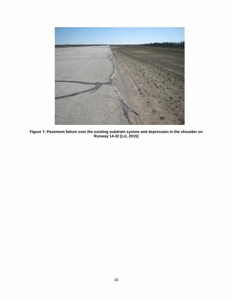
The medium to high severity depressions/settlements and heaves of the pavement on Runway 14-32 are the main concern since they are the primary cause of the pavement bumpiness. Figures 5 to 7 show examples of the typical distresses on Runway 14-32 at Hay River Airport.
3.2 Pavement Structure and Ground Conditions
Runway 14-32 was paved in 1966, so it is almost 50 years old. The pavement structure on Runway 14-32 consists generally of:
150 mm of HMA with localized areas (likely patches) having up to 300 mm HMA ;
200 to 400 mm of gravel with some sand base; and
About 900 mm of silty sand subbase.
The silty sand subbase is underlain by firm to very stiff silty clay to clayey silt subgrade. The subgrade soils are considered to be frost susceptible. The depth of frost penetration in the Hay River Airport area is about 3.0 m. The moisture content of the soils was variable, and some of the soils within the depth of frost penetration could be saturated, at least seasonably. This significantly increases the potential for frost heaving taking into account that the soils are frost susceptible.
3.3 Permafrost and Frost Heaving
Hay River Airport is located in a scattered discontinuous permafrost zone. It is anticipated that due to excessive thawing the depth of the active layer is increasing. The vibrating wire piezometer readings obtained on May 12, 2015 by GNWT indicated that the soil temperature ranged from -1.0°C to +0.9°C. For the purpose of pavement design analysis it should be assumed that the permafrost is melted or melting.
Due to the highly frost susceptible nature of the subgrade soils, in the presence of water and at freezing temperatures, soil lenses will form under the pavement and frost heaves will occur. Frost heaves of various degrees were observed at numerous locations on Runway 14-32, particularly near the pavement edges in the non-keel zones. This is likely due to pavement subsurface drainage failure. The soils, particularly near the pavement edges, are saturated and prone to heaving.
3.4 Drainage Conditions
It was noticed during the May 2015 site visit that the drainage conditions of Runway 14-32 at Hay River Airport were very poor. Surface drainage is provided by a ditch on the northeast side of the runway and Hay River on the southwest side. The entire area is relatively flat grade with poor drainage capabilities.
9
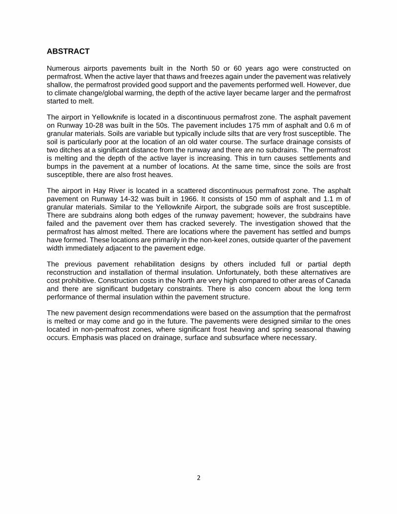
There are 250 mm edge drains located along both edges of the runway pavement. These subdrains were constructed during paving of the runway in 1966; however, the drains are no longer functional. They have collapsed at some locations and are clogged with sand, silt, and gravel. The failure of the subdrain resulted in the failure of the pavement, particularly along the edges. As a short term solution, the catchbasins were capped with heavy duty plastic sheet or with asphalt. There are two outflows from the catchbasins to the Hay River; however, they are not functional. The ditch in front of the outlet from the west subdrain that was inspected during the May, 2015 visit was silted and overgrown with vegetation.
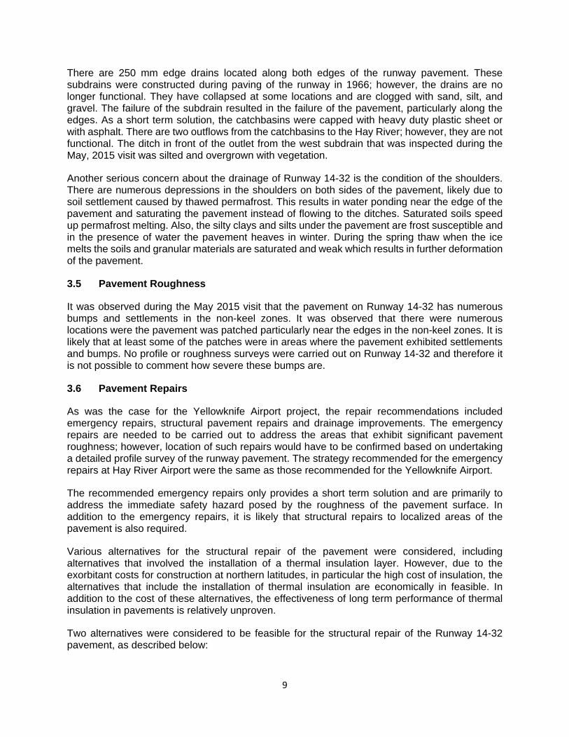
Another serious concern about the drainage of Runway 14-32 is the condition of the shoulders. There are numerous depressions in the shoulders on both sides of the pavement, likely due to soil settlement caused by thawed permafrost. This results in water ponding near the edge of the pavement and saturating the pavement instead of flowing to the ditches. Saturated soils speed up permafrost melting. Also, the silty clays and silts under the pavement are frost susceptible and in the presence of water the pavement heaves in winter. During the spring thaw when the ice melts the soils and granular materials are saturated and weak which results in further deformation of the pavement.
3.5 Pavement Roughness
It was observed during the May 2015 visit that the pavement on Runway 14-32 has numerous bumps and settlements in the non-keel zones. It was observed that there were numerous locations were the pavement was patched particularly near the edges in the non-keel zones. It is likely that at least some of the patches were in areas where the pavement exhibited settlements and bumps. No profile or roughness surveys were carried out on Runway 14-32 and therefore it is not possible to comment how severe these bumps are.
3.6 Pavement Repairs
As was the case for the Yellowknife Airport project, the repair recommendations included emergency repairs, structural pavement repairs and drainage improvements. The emergency repairs are needed to be carried out to address the areas that exhibit significant pavement roughness; however, location of such repairs would have to be confirmed based on undertaking a detailed profile survey of the runway pavement. The strategy recommended for the emergency repairs at Hay River Airport were the same as those recommended for the Yellowknife Airport.
The recommended emergency repairs only provides a short term solution and are primarily to address the immediate safety hazard posed by the roughness of the pavement surface. In addition to the emergency repairs, it is likely that structural repairs to localized areas of the pavement is also required.
Various alternatives for the structural repair of the pavement were considered, including alternatives that involved the installation of a thermal insulation layer. However, due to the exorbitant costs for construction at northern latitudes, in particular the high cost of insulation, the alternatives that include the installation of thermal insulation are economically in feasible. In addition to the cost of these alternatives, the effectiveness of long term performance of thermal insulation in pavements is relatively unproven.
Two alternatives were considered to be feasible for the structural repair of the Runway 14-32 pavement, as described below:
10
1. Cement Stabilization - Remove the existing pavement structure full width and stabilize the existing soils with Portland cement. Then place a new pavement structure. It should be anticipated in this alternative that some frost heaving will very likely still occur and some settlement may also occur. Since the cement treated layers may not be durable in a frost heaving environment, this alternative may only be considered feasible if only a detailed geotechnical investigation is carried out and a pilot-scale trial is undertaken.
2. Geogrid (Pillow) Structure - Remove the existing pavement structure and the top of the existing soil to a predetermined depth. The depth should be based on the required pavement design from structural design analysis and the results of the soil consolidation tests. Place a layer of biaxial geogrid and then 150 mm of granular base material above it. Then place a second layer of the biaxial geogrid. The double geogrid and granular ‘sandwich’ acts as a reinforced support layer for the pavement. Place the remaining part of the pavement structure. Golder does not recommend any insulation in this alternative. Although in this alternative some frost heaving should be anticipated, this alternative offers high flexibility and should provide sufficient durability. This alternative is considered to be the most cost effective.
An overlay over the entire Runway 14-32, due to its relatively high cost, can be considered when the drainage improvements are completed, the water condition are stabilized, and the structural repairs are proven to be effective and are completed over the required areas.
3.7 Drainage Improvements
It was recommended that new subdrains be installed on both sides of the runway. The existing subdrains were likely constructed during runway paving in 1966 so they are almost 50 years old. If proper maintenance is not applied, the subdrains had likely reached the end of their service life some time ago.
The depth of the subdrains should be a minimum 0.5 m below the bottom of the pavement structure. It is also critical that there are enough outlets taking the subsurface water to the ditches. A minimum of two outlets were recommended on each side of Runway 14-. The design of the subdrains along the entire runway would require careful determination of their longitudinal slope.
4.0 Summary
Runway 10-28 at Yellowknife Airport and Runway 14-32 at Hay River Airport were constructed on permafrost is considered 66 and 50 years ago, respectively. Due to global warming and changing the character of the surface the depth of the active layer has increased steadily and currently the permafrost to be melting or is already melted. This resulted in significant settlements of the pavements. Also, since the soils under the runaway pavements are frost susceptible, differential frost having was observed. This results in pavement roughness / bumpiness and pavement cracking.
The recommendations included:
Pavement emergency repairs, particularly addressing the bumpiness of the pavement;
Structural improvements to address medium to long term pavement performance; and

11
Surface and subsurface pavement drainage improvements.
It can be anticipated that similar issues can occur on runway airside pavements at other airports originally constructed on permafrost.

12
REFERENCES
1. Public Works Canada, Architectural and Engineering Services, Air Transportation, ‘Manual of
Pavement Structural Design’, ASG-19 (ak-68-12), July 1992.
2. U.S. Department of Transportation, Federal Aviation Administration, Advisory Circular AC No:
150/5320-6E, “Airport Pavement Design and Evaluation”, Date: 9/30/2009.
3. G.H. Argue, “Canadian Airfield Pavement Engineering Reference”, Ottawa, September 2005.
4. Guy Dore and Hannele K. Zubeck, “Cold Regions Pavement Engineering”, ASCR Press,
McGraw Hill, 2009.
5. Orlando B. Anderson and Branko Ladanyi, “Frozen Ground Engineering”, Second Edition,
ASCE, John Wiley & Sons, Inc., 2004.

13
FIGURES
Figure 1: Severe pavement settlements and longitudinal and transverse cracking in the non-keel zone on Runway 10-28 [GNWT, 2014]
Figure 2: Severe settlements in the non-keel zone on Runway 10-28 and deep depressions on the shoulder [LU, May 2015]

14
Figure 3: Water ponding in a deep pavement depression Runway 10-28 [GNWT, 2014]
Figure 4: Rough sections on Runway 10-28 in April 2015 [GNWT, 2015]
15
Figure 5: Severe transverse crack on Runway 14-32 [LU, 2015]
Figure 6: Settlements in the non-keel zone on Runway 14-32 and depressions on the shoulder [LU, May 2015]
16
Figure 7: Pavement failure over the existing subdrain system and depression in the shoulder on Runway 14-32 [LU, 2015]


![Stream Quality Control via a Constrained Nonlinear Time ... · in [11,12] is extended to deal with nonlinear optimization problems with time delays and system constraints. Then, an](https://static.fdocuments.in/doc/165x107/5f0a9fff7e708231d42c8ce2/stream-quality-control-via-a-constrained-nonlinear-time-in-1112-is-extended.jpg)