UV100E Ultraviolet Air Treatment Systems - Home | National Trade
12
PRODUCT DATA 68-0262-2 fi U.S. Registered Trademark Copyright ' 2002 Honeywell All Rights Reserved UV100E Ultraviolet Air Treatment Systems APPLICATION When installed in forced air heating and cooling systems, the UV100E Ultraviolet Air Treatment Systems kill airborne and surface micro-organism contaminants like mold and bacteria. The UV systems use patent-pending SmartLamp™ control technology that monitors the HVAC system to operate the lamps only when needed. This technology extends lamp life up to five times and reduces power consumption, lowering operating costs. The UV systems also include local diagnostics with the SmartLamp™ LED and reset capability. FEATURES Extended lamp life. SmartLamp™ Control Algorithm determines optimal UV lamp usage. SmartLamp™ LED shows lamp life and replacement. Reduced power consumption. Communicates with other home appliances through Enviracom™ three-wire communications bus. Automatic brownout and high temperature protection for UV lamps. Return air models supplied with integrated airflow sensor to monitor air flowing through ductwork. Dual-purpose reset button: Commands lamps on with a single one-second push. Resets internal lamp run-time timer after lamp replacement with extended five-second hold. UV-C light kills airborne and surface bacteria. UV lamp does not produce ozone. Easy lamp maintenance with quick and easy lamp replacement. Sealed unit design prevents accidental installer and homeowner contact with high voltage and ultraviolet rays. Safe design prevents lamps from lighting unless the base is correctly mounted on the HVAC duct. Light pipe to safely view the lamp operation. Power cord that plugs into 120 Vac electrical outlet. Bold Enviracaire Elite™ look with blue and white styling. Five-year limited warranty. Contents Application ......................................................................... 1 Features ............................................................................ 1 Specifications .................................................................... 2 Ordering Information ......................................................... 2 Installation ......................................................................... 3 Checkout ........................................................................... 6 Troubleshooting and Service ............................................. 7 Maintenance ...................................................................... 7 whole-house air quality system
Transcript of UV100E Ultraviolet Air Treatment Systems - Home | National Trade

PRODUCT DATA
68-0262-2® U.S. Registered TrademarkCopyright © 2002 Honeywell � All Rights Reserved
UV100E UltravioletAir Treatment Systems
APPLICATIONWhen installed in forced air heating and cooling systems, the UV100E Ultraviolet Air Treatment Systems kill airborne and surface micro-organism contaminants like mold and bacteria.
The UV systems use patent-pending SmartLamp� control technology that monitors the HVAC system to operate the lamps only when needed. This technology extends lamp life up to five times and reduces power consumption, lowering operating costs. The UV systems also include local diagnostics with the SmartLamp� LED and reset capability.
FEATURES � Extended lamp life.� SmartLamp� Control Algorithm determines optimal
UV lamp usage.� SmartLamp� LED shows lamp life and replacement.� Reduced power consumption.� Communicates with other home appliances through
Enviracom� three-wire communications bus.� Automatic brownout and high temperature protection
for UV lamps.� Return air models supplied with integrated airflow
sensor to monitor air flowing through ductwork.� Dual-purpose reset button:
� Commands lamps on with a single one-second push.
� Resets internal lamp run-time timer after lamp replacement with extended five-second hold.
� UV-C light kills airborne and surface bacteria.� UV lamp does not produce ozone.� Easy lamp maintenance with quick and easy lamp
replacement.� Sealed unit design prevents accidental installer and
homeowner contact with high voltage and ultraviolet rays.
� Safe design prevents lamps from lighting unless the base is correctly mounted on the HVAC duct.
� Light pipe to safely view the lamp operation.� Power cord that plugs into 120 Vac electrical outlet.� Bold Enviracaire Elite� look with blue and white
styling.� Five-year limited warranty.
ContentsApplication.........................................................................1Features ............................................................................1Specifications ....................................................................2Ordering Information .........................................................2Installation .........................................................................3Checkout ...........................................................................6Troubleshooting and Service.............................................7Maintenance......................................................................7
whole-house air quality system

UV100E ULTRAVIOLET AIR TREATMENT SYSTEMS
68-0262-2 2
ORDERING INFORMATIONWhen purchasing replacement and modernization products from your TRADELINE® wholesaler or distributor, refer to the TRADELINE® Catalog or price sheets for complete ordering number.
If you have additional questions, need further information, or would like to comment on our products or services, please write:
1. Your local Home and Building Control Sales Office (check white pages of your phone directory).2. Home and Building Control Customer Relations
Honeywell, 1885 Douglas Drive NorthMinneapolis, Minnesota 55422-4386
In Canada�Honeywell Limited/Honeywell Limitée, 35 Dynamic Drive, Scarborough, Ontario M1V 4Z9.International Sales and Service Offices in all principal cities of the world. Manufacturing in Australia, Canada, Finland, France, Germany, Japan, Mexico, Netherlands, Spain, Taiwan, United Kingdom, U.S.A.
SPECIFICATIONSIMPORTANT
This product is tested and calibrated under closely controlled conditions and some minor differences in performance can be expected if those conditions are changed. The specifications in this publication do not include normal manufacturing tolerances; therefore, an individual unit may not exactly match the listed specifications.
TRADELINE® Models available:The UV100E Ultraviolet Air Treatment System is available in three models: a single-lamp, moderate-efficiency return air unit; a dual-lamp, high-efficiency return air unit; and an air conditioner coil irradiation unit.
� UV100E single-lamp and dual-lamp return air units are mounted in the return air duct of an HVAC system. The units have high-efficiency performance against airborne bacteria in return air applications.� Without Enviracom hooked up: monitors air flowing
through ductwork using supplied airflow sensor mounted to backside of unit. Operates lamps when air is flowing (120 fpm minimum), leaving lamps on for 40 minutes after airflow stops. If airflow resumes during the 40 minutes, the timer resets to 40 minutes. When no airflow is detected for 40 minutes, the lamps turn off until the next occurrence of airflow.
� With Enviracom hooked up: monitors thermostat load information instead of using airflow sensor to operate on and off.
� UV100E coil irradiation unit is mounted in the supply-side air duct or downstream or upstream from air conditioner evaporator coils in HVAC system. It reduces mold growth and spores on duct surfaces, coils and drip pans. � Does not use an airflow sensor.� Without Enviracom hooked up: operates steady on/off
cycle: lamp operates three hours on, three hours off for a total two-year life cycle.
� With Enviracom hooked up: after initial three hours run time, operates three hours on and three hours off dur-ing times when the evaporator A-coil may be exposed to moisture, including when the control sees a cooling call and for 30 days after the last cooling occurred. This operation extends the lamp life beyond two years.
Efficiencies:� UV100E Coil Irradiation unit: Kills up to 99.9% of mold on
system cooling coils.� Test performed in a test duct showed reduction in col-
ony-forming aspergillus niger mold spores when sur-face was irradiated at a distance of 18 in. for three hours in still air, using new lamps.
� UV100A Dual-Lamp Return unit: Kills up to 87% of airborne bacterial passing by the system.� Test showed single-pass kill-rate of serratia marce-
scens bacteria in a clean metal 12 in. x 25 in. duct at an airflow rate of 2000 cfm using new lamps.
� UV100A Single-Lamp Return unit: Kills up to 70% of airborne bacteria passing by the system.� Test showed single-pass kill-rate of serratia marce-
scens bacteria in a clean metal 12 in. x 25 in. duct at an airflow rate of 2000 cfm using new lamps.
Enviracom� Communications Capabilities:� Communicates with homeowner through three-wire
communication bus using 24 Vac thermostat connections.� Hooked up to single-lamp and dual-lamp return air
models: uses thermostat load information instead of airflow sensor.
� Hooked up to coil irradiation mode: uses thermostat load information to operate during times evaporator A-coil may be exposed to moisture to extend lamp life beyond two years.
� Sends messages to communicate reset and receives remote reset, when available.� Lamp change indication cannot be reset by cycling
power.� When Enviracom is transmitting messages, shows
flashing green Enviracom LED on bottom of unit. � Other messages include percent of lamp remaining,
internal faults, and lamps energized.� Control calculates percent of lamp run time/starts
remaining and sends out this information through an Enviracom message.
� When Enviracom is transceiving messages, shows solid green Enviracom LED on bottom of unit.
Approvals:Underwriters Laboratories: File no. E212213.
The health aspects associated with the use of this product and its ability to aid in disinfection of environmental air have not been investigated by UL.
UV100E ULTRAVIOLET AIR TREATMENT SYSTEMS
3 68-0262-2
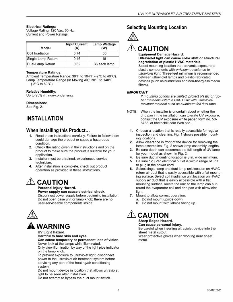
Electrical Ratings:Voltage Rating: 120 Vac, 60 Hz.Current and Power Ratings:
Temperature Ratings:Ambient Temperature Range: 30°F to 104°F (-2°C to 40°C).Lamp Temperature Range (In Moving Air): 30°F to 140°F
(-2°C to 60°C).
Relative Humidity: Up to 95% rh, non-condensing.
Dimensions:See Fig. 2.
INSTALLATION
When Installing this Product�1. Read these instructions carefully. Failure to follow them
could damage the product or cause a hazardous condition.
2. Check the rating given in the instructions and on the product to make sure the product is suitable for your application.
3. Installer must be a trained, experienced service technician.
4. After installation is complete, check out product operation as provided in these instructions.
CAUTIONPersonal Injury Hazard. Power supply can cause electrical shock.Disconnect power supply before beginning installation. Do not open base unit or lamp knob; there are no user-serviceable components inside.
WARNINGUV Light Hazard. Harmful to bare skin and eyes. Can cause temporary or permanent loss of vision.Never look at the lamps while illuminated.Only view illumination by way of the light pipe indicator on the lamp knob.To prevent exposure to ultraviolet light, disconnect power to the ultraviolet air treatment system before servicing any part of the heating/air conditioning system.Do not mount device in location that allows ultraviolet light to be seen after installation.Do not attempt to bypass the duct mount switch.
Selecting Mounting Location
CAUTIONEquipment Damage Hazard. Ultraviolet light can cause color shift or structural degradation of plastic HVAC materials.Select mounting location that prevents exposure to plastic components with unknown resistance to ultraviolet light. Three-feet minimum is recommended between ultraviolet lamps and plastic-fabricated devices (such as humidifiers and non-fiberglass media filters).
IMPORTANTIf mounting options are limited, protect plastic or rub-ber materials listed in CAUTION with ultraviolet-resistant material such as aluminum foil duct tape.
NOTE: When the installer is uncertain about whether the drip pan in the installation can tolerate UV exposure, consult the UV exposure white paper, form no. 50-8788, at hbctechlit.com Web site .
1. Choose a location that is readily accessible for regular inspection and cleaning. Fig. 1 shows possible mount-ing locations.
2. Allow clearance in front of the device for removing the lamp assemblies. Fig. 2 shows lamp assembly lengths.
3. Be sure depth can accommodate full length of UV lamp for your model as shown in Fig. 2.
4. Be sure duct mounting location is 8 in. wide minimum.5. Be sure 120 Vac electrical outlet is within range of unit
to plug in the power cord.6. Select single-lamp and dual-lamp unit location on HVAC
return air duct that is easily accessible with a flat mount-ing surface. Select coil irradiation unit location on HVAC supply air duct that is easily accessible with a flat mounting surface; locate the unit so the lamp can sur-round the evaporator coil and drip pan with ultraviolet light.
7. Mount to allow correct operation:a. Do not mount upside down.b. Do not mount with lalmps facing up.
CAUTIONSharp Edges Hazard.Can cause personal injury.Be careful when inserting ultraviolet device into the sheet metal cutout.Wear protective gloves when working near sheet metal.
ModelInput Current
(A)Lamp Wattage
(W)Coil Irradiation 0.74 36Single-Lamp Return 0.46 18Dual-Lamp Return 0.62 36 each lamp

UV100E ULTRAVIOLET AIR TREATMENT SYSTEMS
68-0262-2 4
Duct MountingUse the following instructions to mount the UV air treatment system on the air duct of an HVAC system:
1. Disconnect power to the HVAC system before installing the Ultraviolet Air Treatment System.
2. Select the appropriate template for your model (see Fig. 5-7).
3. Place the appropriate template for your model on the duct surface, centering the lamp hole(s) on the duct.
4. Mark the location on the duct for 2 in. diameter lamp hole(s), unit mounting-screw pilot holes, and when installing a return air model, the 1-1/2 in. airflow sensor hole.
5. Cut 2 in. lamp hole(s) and 1-1/2 in. airflow sensor hole in the duct. Remove any burrs. Note that the airflow sensor protrudes out of backside of device. Be careful to avoid scratching or damaging the airflow sensor.
6. Use a 3/32- in. drill for pilot holes for mounting screws.7. Be sure duct surface is flat after all holes are drilled.8. Position entire base unit on duct. Be sure lamp and air-
flow sensor holes in duct align with unit holes. Be care-ful to avoid scratching or damaging the airflow sensor.
9. Install unit into duct using three (or two, depending on model) no.10, 2 in. Phillips head sheet metal mounting screws provided. (A spare screw is provided for three-screw model.)
10. Tighten screws to 12 to 14 in.-lb so space between case and duct is sealed.
Fig. 1. Possible mounting locations for Ultraviolet Air Treatment Systems.
CONDITIONED AIRTO ROOM
HEATEXCHANGER
RETURNAIR
FURNACE
CONDENSATEDRAIN
CONDENSERCOOLING AIR
REMOTE CONDENSERSECTION (HIGH SIDE)
REFRIGERANTPIPING
SINGLE-LAMPAND DUAL-LAMP
UNIT LOCATION
COIL IRRADIATIONUNIT LOCATION
M13529A
ELECTRONIC AIR CLEANER
HIGH EFFICIENCYAIR CLEANER

UV100E ULTRAVIOLET AIR TREATMENT SYSTEMS
5 68-0262-2
Fig. 2. Ultraviolet AIr Treatment System dimensions in in. (mm).
2-1/4 (57)
3-1/2 (89)4-1/2 (114)
7 (178)
1(25)
7(178)
3-1/2(89)
4 (102) 14-7/8 (379)
M20190
COIL IRRADIATION
2-1/4 (57)
3-1/2 (89)4-1/2 (114)
7 (178)
1(25)
7(178)
3-1/2(89)
4 (102)7-7/16 (188)
SINGLE-LAMP RETURN
1/2 (12)
M20191
3-1/2 (89)
5 (127)
7 (178)
10 (254)
2-3/16(56)8-1/2
(216)
3-1/4(83)
4 (102)14-7/8 (379)
1/2 (12)
M20192
3-1/2 (89)
5 (127)
DUAL-LAMPRETURN

UV100E ULTRAVIOLET AIR TREATMENT SYSTEMS
68-0262-2 6
CAUTIONBreakable Glass Hazard.Can cause personal injury.Be careful when inserting lamps(s) into lamp base.Wear protective gloves when handling lamp(s).
MERCURY NOTICEThis device contains mercury in the sealed ultraviolet lamp(s). Do not place your used lamp(s) in the trash. Dispose of properly.
Broken Lamp Cleanup.Do not use a household vacuum.Sweep debris into a plastic bag and dispose of properly.
Contact your local waste management authority for instructions regarding recycling and the proper disposal of old lamp(s).
11. Insert the lamp into the base unit with the light-pipe indi-cator at the eleven o�clock position (left of the raised button on the unit cover). Do not touch the lamp sur-face with your hands.
12. Continue lightly pushing in on the lamp while rotating it slowly counterclockwise. This should cause the lamp to drop into the bottom of the lamp well.
13. Rotate the lamp clockwise until it snaps into place with the light pipe indicator aligned with the raised button on the unit cover.
WARNINGUV Light Hazard.Harmful to bare skin and eyes. Can cause temporary or permanent loss of vision.Never look at the lamps while illuminated.Only view illumination by way of the light pipe indicator located on the lamp knob.To prevent exposure to ultraviolet light, disconnect power to the ultraviolet air treatment system before servicing any part of the heating/air conditioning system.
NOTE: If you desire to communicate with other appliances using your Enviracom communication bus, go on to step 14; if not, go directly to step 15.
14. Hook up corresponding appliance wires to the Envira-com communication bus located on the bottom of the UV device base. Be sure to loop wire of other
Enviracom appliances or Enviracom common node around the UV base Enviracom screw terminals 1, 2 and 3. See Fig. 3.
15. Plug the cord into the nearby 120 Vac electrical outlet.
Fig. 3. Looping Enviracom appliance or common node wire around UV Enviracom base screw terminals.
16. Wait ten minutes for the airflow sensor to calibrate. Dur-ing this time, the furnace fan must remain Off.
NOTE: Failure to wait ten minutes for the airflow sensor to calibrate before powering the furance causes the air-flow sensor to incorrectly calibrate and the device to incorrectly function. If this occurs, remove power to the furnace or turn off the system and fan, wait ten minutes, and then resume normal furnace opera-tion.
17. Reconnect the power to the HVAC system.18. Choose a location on the adjacent HVAC equipment for
the HVAC maintenance label included in the air treatment system packing box. Choose a location that a future installer can easily see during any future HVAC maintenance or repair.
19. Adhere the HVAC maintenance label to the HVAC equipment (selected in step 17) such as the furnace, air cleaner or humidifier.
CHECKOUTThe installer should verify that the ultraviolet lamp(s) are operating only by viewing the light pipe indicator on the lamp knob. Do not attempt to look directly into the duct to see the illuminated ultraviolet lamps.
The installer should orient the homeowner to the unit by showing them the blue glow of the light pipe indicator and discussing how to determine when the unit is functioning properly without looking directly into the duct to see the illuminated ultraviolet lamps. The installer should also emphasize the hot surface and electrical shock safety warnings.
1
RESET
2 3 M20242
UV100E ULTRAVIOLET AIR TREATMENT SYSTEMS
7 68-0262-2
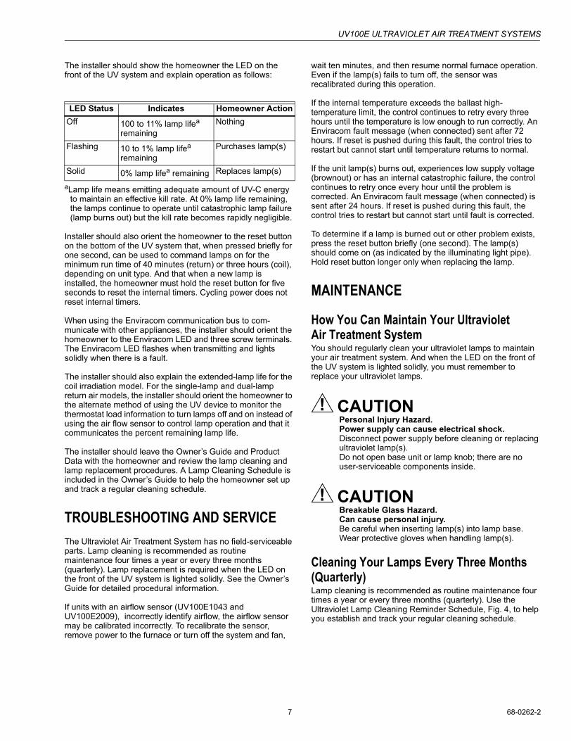
The installer should show the homeowner the LED on the front of the UV system and explain operation as follows:
aLamp life means emitting adequate amount of UV-C energy to maintain an effective kill rate. At 0% lamp life remaining, the lamps continue to operate until catastrophic lamp failure (lamp burns out) but the kill rate becomes rapidly negligible.
Installer should also orient the homeowner to the reset button on the bottom of the UV system that, when pressed briefly for one second, can be used to command lamps on for the minimum run time of 40 minutes (return) or three hours (coil), depending on unit type. And that when a new lamp is installed, the homeowner must hold the reset button for five seconds to reset the internal timers. Cycling power does not reset internal timers.
When using the Enviracom communication bus to com-municate with other appliances, the installer should orient the homeowner to the Enviracom LED and three screw terminals. The Enviracom LED flashes when transmitting and lights solidly when there is a fault.
The installer should also explain the extended-lamp life for the coil irradiation model. For the single-lamp and dual-lamp return air models, the installer should orient the homeowner to the alternate method of using the UV device to monitor the thermostat load information to turn lamps off and on instead of using the air flow sensor to control lamp operation and that it communicates the percent remaining lamp life.
The installer should leave the Owner�s Guide and Product Data with the homeowner and review the lamp cleaning and lamp replacement procedures. A Lamp Cleaning Schedule is included in the Owner�s Guide to help the homeowner set up and track a regular cleaning schedule.
TROUBLESHOOTING AND SERVICEThe Ultraviolet Air Treatment System has no field-serviceable parts. Lamp cleaning is recommended as routine maintenance four times a year or every three months (quarterly). Lamp replacement is required when the LED on the front of the UV system is lighted solidly. See the Owner�s Guide for detailed procedural information.
If units with an airflow sensor (UV100E1043 and UV100E2009), incorrectly identify airflow, the airflow sensor may be calibrated incorrectly. To recalibrate the sensor, remove power to the furnace or turn off the system and fan,
wait ten minutes, and then resume normal furnace operation. Even if the lamp(s) fails to turn off, the sensor was recalibrated during this operation.
If the internal temperature exceeds the ballast high-temperature limit, the control continues to retry every three hours until the temperature is low enough to run correctly. An Enviracom fault message (when connected) sent after 72 hours. If reset is pushed during this fault, the control tries to restart but cannot start until temperature returns to normal.
If the unit lamp(s) burns out, experiences low supply voltage (brownout) or has an internal catastrophic failure, the control continues to retry once every hour until the problem is corrected. An Enviracom fault message (when connected) is sent after 24 hours. If reset is pushed during this fault, the control tries to restart but cannot start until fault is corrected.
To determine if a lamp is burned out or other problem exists, press the reset button briefly (one second). The lamp(s) should come on (as indicated by the illuminating light pipe). Hold reset button longer only when replacing the lamp.
MAINTENANCE
How You Can Maintain Your Ultraviolet Air Treatment SystemYou should regularly clean your ultraviolet lamps to maintain your air treatment system. And when the LED on the front of the UV system is lighted solidly, you must remember to replace your ultraviolet lamps.
CAUTIONPersonal Injury Hazard.Power supply can cause electrical shock.Disconnect power supply before cleaning or replacing ultraviolet lamp(s).Do not open base unit or lamp knob; there are no user-serviceable components inside.
CAUTIONBreakable Glass Hazard.Can cause personal injury.Be careful when inserting lamp(s) into lamp base.Wear protective gloves when handling lamp(s).
Cleaning Your Lamps Every Three Months (Quarterly)Lamp cleaning is recommended as routine maintenance four times a year or every three months (quarterly). Use the Ultraviolet Lamp Cleaning Reminder Schedule, Fig. 4, to help you establish and track your regular cleaning schedule.
LED Status Indicates Homeowner ActionOff 100 to 11% lamp lifea
remainingNothing
Flashing 10 to 1% lamp lifea remaining
Purchases lamp(s)
Solid 0% lamp lifea remaining Replaces lamp(s)

UV100E ULTRAVIOLET AIR TREATMENT SYSTEMS
68-0262-2 8
MERCURY NOTICEThis device contains mercury (less than 5 mg) in the sealed ultraviolet lamp(s). Do not place your used lamp(s) in the trash. Dispose of properly.
Broken Lamp Cleanup. Do not use a household vacuum. Sweep debris into a plastic bag and dispose of properly.
Contact your local waste management authority for instructions regarding recycling and the proper disposal of old lamp(s).
CAUTIONUV Lamp Burn Hazard.Harmful to bare skin.Can cause severe burns.Disconnect power 15 minutes before removing the ultraviolet lamp(s)
Fig. 4. Ultraviolet lamp cleaning reminder schedule.
To clean your lamps:1. Disconnect the power to your HVAC system.2. Unplug your ultraviolet air treatment system cord from
the electrical outlet and allow the lamps to cool for at least 15 minutes.
3. Rotate your lamp knob counterclockwise and gently pull the lamp knob to remove the lamp(s).
4. Holding only the lamp knob, wipe the lamp glass using a soft cloth with window cleaner applied to it. Do not touch the lamp surface with your hands. Use only the cloth.
5. To ensure that the light pipe indicator continues to func-tion, use a moistened cotton swab to gently remove any dust that may have collected between the light indicator on the base and the black lamp base.
6. Wipe your lamps with a clean, dry cloth.7. Put your clean lamps back into the unit base by follow-
ing Replacing Your Lamps section steps 5, 6, and 7.
WARNINGUV Light Hazard.Harmful to bare skin and eyes.Can cause temporary or permanent loss of vision.Never look at the lamps while illuminated. Only view illumination by way of the light pipe indicator located on the lamp knob. To prevent exposure to ultraviolet light, disconnect power to ultraviolet air treatment system before servicing any part of heating/air conditioning system.
8. Plug the cord into the nearby 120 Vac electrical outlet.9. Verify that ultraviolet lamp(s) are operating only by view-
ing through light pipe indicator on lamp knob. Never look directly at your lamps while illuminated.
10. Reconnect the power to your HVAC system.
CAUTIONUV Lamp Burn Hazard.Harmful to bare skin.Can cause severe burns.Disconnect power 15 minutes before removing the ultraviolet lamp(s).
Replacing Your LampsReplacement of your lamps is required when LED on front of the unit is lighted solidly.
NOTE: LED blinking slowly, one second on and one second off, indicates that ten percent or less of lamp life remains and homeowner must order new lamp(s).
IMPORTANTAnytime the reset button is pushed, the lamp(s) should come on (as indicated by the illuminating light pipe). To determine if a lamp is burned out or other problem exists, press the reset button briefly (one second). Hold reset button longer (five seconds) only when replacing lamp.
To replace your lamps:1. Select and obtain the correct replacement lamp for your
unit. See Parts List.2. Disconnect the power to your HVAC system.3. Unplug your ultraviolet air treatment system cord from
the electrical outlet and allow the lamps to cool for at least 15 minutes.
4. Rotate the lamp knob counterclockwise and gently pull the lamp knob to remove the lamp(s).
5. Insert the lamp into the base unit with the light pipe indi-cator at the eleven o�clock position (left of the raised button on the unit cover). Do not touch the lamp sur-face with your hands.
6. Continue lightly pushing in on lamp while rotating it slowly counterclockwise until lamp to drops into bottom of lamp well.
7. Rotate lamp clockwise until it snaps into place with light pipe indicator aligned with raised button on unit cover.
YEAR
UV LAMP CLEANING REMINDER SCHEDULE
, (year)
M13516
J F M A M J J A S O N D
INSTALLATION DATE: (month)
UV100E ULTRAVIOLET AIR TREATMENT SYSTEMS
9 68-0262-2
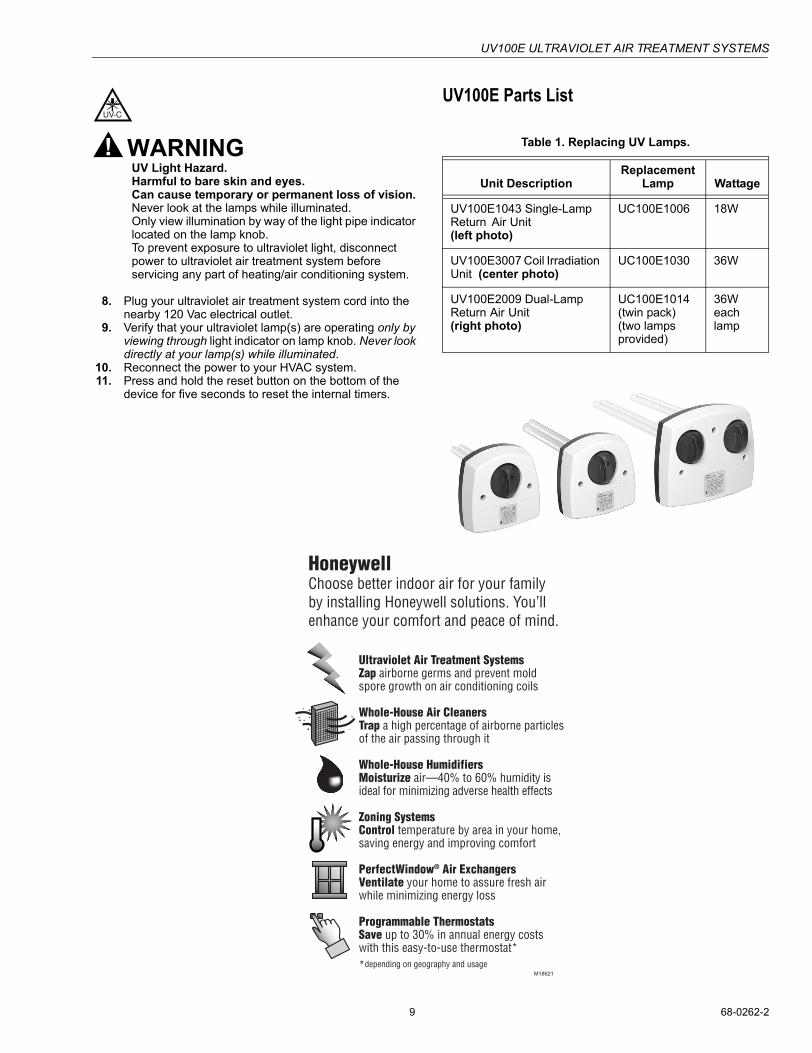
WARNINGUV Light Hazard.Harmful to bare skin and eyes.Can cause temporary or permanent loss of vision.Never look at the lamps while illuminated. Only view illumination by way of the light pipe indicator located on the lamp knob.To prevent exposure to ultraviolet light, disconnect power to ultraviolet air treatment system before servicing any part of heating/air conditioning system.
8. Plug your ultraviolet air treatment system cord into the nearby 120 Vac electrical outlet.
9. Verify that your ultraviolet lamp(s) are operating only by viewing through light indicator on lamp knob. Never look directly at your lamp(s) while illuminated.
10. Reconnect the power to your HVAC system.11. Press and hold the reset button on the bottom of the
device for five seconds to reset the internal timers.
UV100E Parts List
Table 1. Replacing UV Lamps.
Unit DescriptionReplacement
Lamp Wattage
UV100E1043 Single-Lamp Return Air Unit (left photo)
UC100E1006 18W
UV100E3007 Coil Irradiation Unit (center photo)
UC100E1030 36W
UV100E2009 Dual-LampReturn Air Unit (right photo)
UC100E1014 (twin pack)(two lamps provided)
36W each lamp

UV100E ULTRAVIOLET AIR TREATMENT SYSTEMS
68-0262-2 10
Fig. 5. Single-Lamp Return Air Ultraviolet Air Treatment System template.
(Dual-Lamp Return Air Ultraviolet Air Treatment System template is located on next page.)
Fig. 6. Dual-Lamp Return Air Ultraviolet Air Treatment System template.
M20194
CENTER OF 2 IN. (51 MM)HOLE FOR LAMP
1-1/2 IN. (38) HOLE FORAIRFLOW SENSOR
CENTER OF AIRFLOW SENSOR HOLE
3/32 IN. (3 MM) PILOT HOLESFOR MOUNTING SCREWS
ALIGN EITHER OF THESE LINES AS CLOSE AS POSSIBLE TO DUCT CENTER LINE
INSTALLATION TEMPLATE FOR SINGLE-LAMP RETURN UNIT.

UV100E ULTRAVIOLET AIR TREATMENT SYSTEMS
11 68-0262-2
M20
195
CE
NT
ER
S O
F 2
IN. (
51 M
M)
HO
LES
FO
R L
AM
P
3/32
IN. (
3 M
M)
PIL
OT
HO
LES
FO
R M
OU
NT
ING
SC
RE
WS
ALI
GN
EIT
HE
R O
F T
HE
SE
LIN
ES
A
S C
LOS
E A
S P
OS
SIB
LE T
O
DU
CT
CE
NT
ER
LIN
E
INS
TAL
LA
TIO
N T
EM
PL
AT
E
FO
R D
UA
L-L
AM
P R
ET
UR
N U
NIT
3/32
IN. (
3 M
M)
PIL
OT
HO
LES
FO
R M
OU
NT
ING
SC
RE
WS
CE
NT
ER
OF
AIR
FLO
W
SE
NS
OR
HO
LE
1-1/
2 IN
. (38
) H
OLE
FO
RA
IRF
LOW
SE
NS
OR

68-0262-2 G.H. Rev. 7-02 www.honeywell.com/yourhome
Automation and Control SolutionsHoneywell Honeywell Limited-Honeywell Limitée1985 Douglas Drive North 35 Dynamic DriveGolden Valley, MN 55422 Scarborough, Ontario
M1V 4Z9
Printed in U.S.A. on recycled paper containing at least 10% post-consumer paper fibers.
UV100E ULTRAVIOLET AIR TREATMENT SYSTEMS
Fig. 7. Coil Irradiation Ultraviolet AIr Treatment System template.
M20193
CENTER OF 2 IN. (51 MM)HOLE FOR LAMP
3/32 IN. (3 MM) PILOT HOLESFOR MOUNTING SCREWS
ALIGN EITHER OF THESE LINES AS CLOSE AS POSSIBLE TO DUCT CENTER LINE
INSTALLATION TEMPLATE FOR COIL IRRADIATION UNIT.