UtiliSwitch - irp-cdn.multiscreensite.com · UtiliSwitch™ Operation Manual. UtiliSwitch user...
10
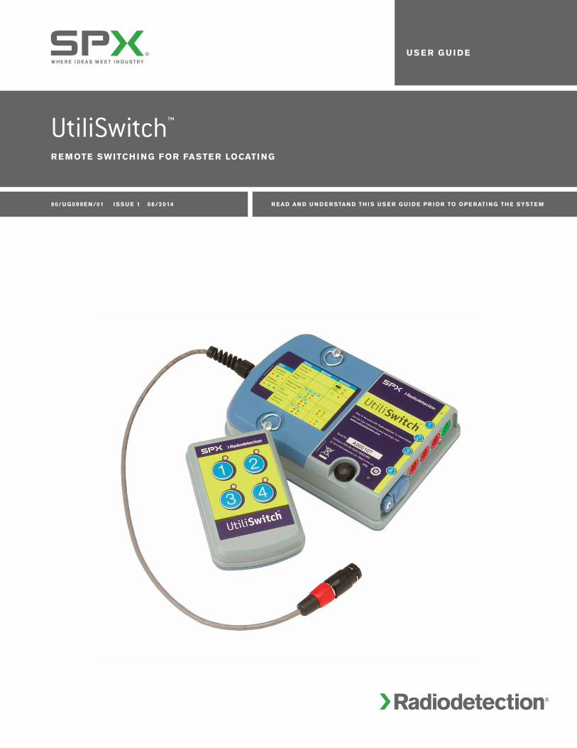
UtiliSwitch ™ REMOTE SWITCHING FOR FASTER LOCATING 90/UG099 EN/01 ISSUE 1 08/2014 READ AND UNDERSTAND THIS USER GUIDE PRIOR TO OPERATING THE SYSTEM USER GUIDE
Transcript of UtiliSwitch - irp-cdn.multiscreensite.com · UtiliSwitch™ Operation Manual. UtiliSwitch user...
UtiliSwitch™
R e mote Switch i ng FoR FaSte R Locati ng
90/ Ug099e n /01 i SSU e 1 08/2014 R ead an d U n d e R Stan d th i S US e R g U i d e pR ioR to ope Rati ng th e SySte m
US e R g U i d e

2 UtiliSwitch user guide
contents
1. UtiliSwitch Features 3
2. Overview 4
3. Installing batteries in UtiliSwitch 4
4. Preparing UtiliSwitch for use 5
5. Connection and operation 6
6. Status indications 7
7. UtiliSwitch Product Specifications 8
8. Part numbers 8
9. Compliance 9
© 2014 Radiodetection Ltd. All rights reserved. Radiodetection is a subsidiary of SPX Corporation. SPX, the green “>” and “X” are trademarks of SPX Corporation, Inc. UtiliSwitch and RD8000 are trademarks of Radiodetection. Due to a policy of continued development, we reserve the right to alter or amend any published specification without notice. This document may not be copied, reproduced, transmitted, modified or used, in whole or in part, without the prior written consent of Radiodetection Ltd.
To see the full range of products and services provided by Radiodetection visit: www.radiodetection.com
UtiliSwitch™ Operation Manual

UtiliSwitch user guide 3
1. UtiliSwitch Features
Figure 2. UtiliSwitch Remote
Power button
Channel selection buttons
and LEDs
Battery compartment D-rings
Earth connection
LED
Belt clip
Output 4
Tx compatible
Outputs 1, 2 and 3
banana plugs
Input from Tx Transmitter
Battery compartment
screws
Figure 1. UtiliSwitch Switcher

4 UtiliSwitch user guide
WARNING! Direct connection to live conductors is POTENTIALLY LETHAL. Direct connections to live conductors should only be attempted by fully qualified personnel using the relevant products that allow connections to energized lines
WARNING! The transmitter is capable of outputting potentially lethal voltages. Take care when applying signals to any pipe or cable and be sure to notify other technicians who may be working on the line.
WARNING! The transmitter is capable of outputting potentially lethal voltages. UtiliSwitch is only to be used by competent personnel familiar with the operating instructions of Radiodetection’s Tx transmitter products.
Ensure that appropriate measures have been taken to protect the general public from the live locate circuits, particularly when switching outputs.
Use of UtiliSwitch for any other purpose is expressly forbidden.
Ensure UtiliSwitch and Tx transmitter are turned off when connecting or disconnecting.
WARNING! Switch off UtiliSwitch Switcher and disconnect cables before changing batteries.
WARNING! UtiliSwitch is NOT approved for use in areas where hazardous gases may be present.
UtiliSwitch Switcher contains devices that emit radio frequency energy during the operation of certain product features. While the devices are pairing, optimizing communications or sending commands to each other always ensure a minimum separation of 8 inches (200mm) between the antenna and your body.
Battery disposal
Batteries should be disposed of in accordance with your company’s work practice, and / or the relevant laws or guidelines in your country or municipality.
training
Radiodetection provides training services for most Radiodetection products. Our qualified instructors will train equipment operators or other personnel at your preferred location or at Radiodetection headquarters.
For more information go to www.radiodetection.com or contact your local Radiodetection representative.
2. OverviewUtiliSwitch™ Switcher has been designed to switch the output of Radiodetection™ Tx transmitter products to up to four outputs remotely.
3. Installing batteries in UtiliSwitchNOTE: Ensure that the batteries are installed with the correct polarity as marked in the battery compartments.
Undo the two D-rings on UtiliSwitch Switcher to access the battery compartment (see Figure 1).
Undo the two Phillips screws on UtiliSwitch Remote to access the battery compartment (see Figure 2).
UtiliSwitch user guide 5
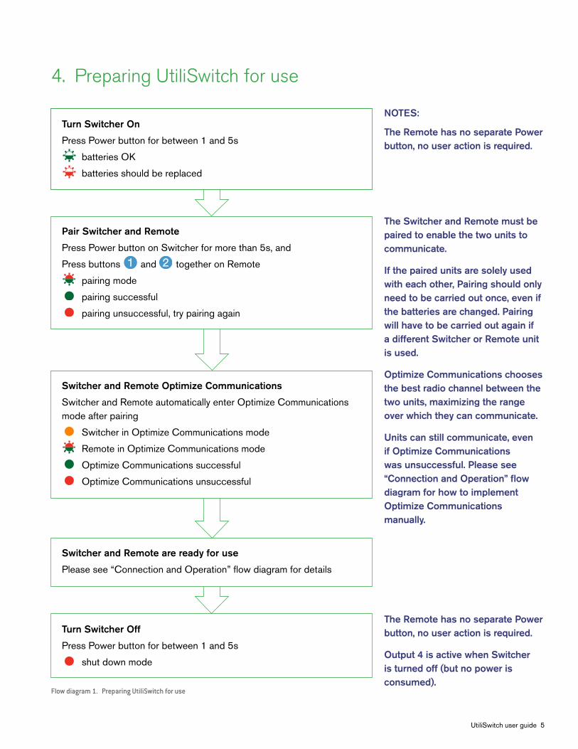
4. Preparing UtiliSwitch for use
Turn Switcher On
Press Power button for between 1 and 5s
batteries OK
batteries should be replaced
Pair Switcher and Remote
Press Power button on Switcher for more than 5s, and
Press buttons and together on Remote
pairing mode
pairing successful
pairing unsuccessful, try pairing again
Switcher and Remote Optimize Communications
Switcher and Remote automatically enter Optimize Communications mode after pairing
Switcher in Optimize Communications mode
Remote in Optimize Communications mode
Optimize Communications successful
Optimize Communications unsuccessful
Switcher and Remote are ready for use
Please see “Connection and Operation” flow diagram for details
Turn Switcher Off
Press Power button for between 1 and 5s
shut down mode
Flow diagram 1. Preparing UtiliSwitch for use
NOTES:
The Remote has no separate Power button, no user action is required.
The Switcher and Remote must be paired to enable the two units to communicate.
If the paired units are solely used with each other, Pairing should only need to be carried out once, even if the batteries are changed. Pairing will have to be carried out again if a different Switcher or Remote unit is used.
Optimize Communications chooses the best radio channel between the two units, maximizing the range over which they can communicate.
Units can still communicate, even if Optimize Communications was unsuccessful. Please see “Connection and Operation” flow diagram for how to implement Optimize Communications manually.
The Remote has no separate Power button, no user action is required.
Output 4 is active when Switcher is turned off (but no power is consumed).

6 UtiliSwitch user guide
5. Connection and operation
WARNING! Ensure UtiliSwitch and Tx transmitter are turned off when connecting or disconnecting cables.
Please refer to Figures 1 and 2.
Connect Switcher to Tx Transmitter
Plug Switcher input cable to Tx Transmitter output socket
Provide a ground return path
Connect the Tx Earth Reel to the Earth connection on the Switcher and a suitable earth return as usual, such as a ground stake
Connect up to four Switcher outputs
Connect to the utilities to be located using the leads provided. Output 4 can be connected to a Tx-compatible Direct Connect lead set or Clamp
Turn on Switcher and Tx Transmitter
See instructions above for powering and pairing Switcher and Remote
Apply Tx Transmitter signal to chosen utility
Press and hold a numbered Remote channel select button until the LED flashes green to select the relevant output.
channel select command being sent
switch successful
confirmation that the channel has switched has not been received from Switcher
If range degrades, Optimize Communications manually
Press buttons and together on Remote
Switcher in Optimize Communications mode
Remote in Optimize Communications mode
Optimize Communications successful
Optimize Communications unsuccessful
NOTES:
For more details regarding earth returns, please see the RD8000™ Cable and Pipe or RD8000 Cable, Pipe and Marker Operation Manual.
If Output 4 is connected to compatible Tx Direct Connect leads, the black lead must be connected to a suitable earth return, such as a ground stake.
Switcher and Remote must be paired to enable the two units to communicate.
The active output will switch off before the new selection is switched on
The new channel may be active even if a red LED displays. It is recommended that you press the Channel Select button again.
Flow diagram 2. Connection and operation

UtiliSwitch user guide 7
6. Status indications
Uti Li Switch Switch e R:
User action Button press time (s) Switcher action Led color Led indication
None Off Off
To turn on 1 to 5s Switcher is turning on, battery is OK Flashing fast
1 to 5s Switcher is turning on, battery is low Flashing fast
Switcher is on, waiting for a command, battery is OK Flashing slow
Switcher is on, waiting for a command, battery is low Flashing slow
To turn off 1 to 5s Switcher is turning off Solid for 2s
To Pair Over 5s Switcher is in Pairing mode. Flashing alternately
Pairing was successful Solid for 3s
Pairing failed Solid for 3s
To Optimize Switcher and Remote are Optimizing Communications
See Remote Communication channels Solid
Communications were optimized successfully Solid for 3s
Communications were not optimized successfully Solid for 3s
Table 1. Summary of UtiliSwitch Switcher status indications
Uti Li Switch R e mote:
User action Button press time (s) Remote action Led color Led indicators
None Off Off
Select Channel or Remote is sending a command Channel LED flashing fast for more than 0.5s
Success – Switcher Output Channel Selected Channel LED Solid for 3s
No response from Switcher1 Channel LED Solid for 3s
To Pair 1 to 30s Press and hold buttons and together LED Position 1 flashing alternately
Pairing successful LED Position 2 solid for 3s
Pairing failed LED Position 2 solid for 3s
To Optimize Press and hold buttons and together LED Position 3 Flashing Communications
1 to 30s alternately
Optimization successful LED Position 4 solid for 3s
Optimization failed LED Position 4 solid for 3s
Table 2. Summary of UtiliSwitch Remote status indications
NOTES: 1 A Channel Select command may have been executed by the Switcher even if no response is received by the Remote.

8 UtiliSwitch user guide
7. UtiliSwitch Product Specifications
Operating and storage temperature range -20ºC to +50ºC
Environmental protection IP54
Batteries Switcher: 2xAlkaline D-cells (LR20) or NiMH (HR20)
Remote: 2xAlkaline AA-cells (LR6) or NiMH (HR6)
Unit weight Remote: 0.23lb (0.10kg) Including batteries: 0.34lb (0.15kg) Excluding batteries
Switcher: 2.35lb (1.07kg) Including batteries and leads 1.74lb (0.79kg) Including batteries 1.11lb (0.50kg) Excluding batteries
Signal switching rating 10W max
Maximum signal current 1.0A rms
Maximum signal voltage 125Vrms / 250Vpk
Maximum VA 10VA
Maximum “foreign” signal 30V AC rms, (50/60Hz) The system will continue to function correctly with an existing voltage on the target utility up to but not exceeding the Max foreign signal
Accidental connection protection 250V AC rms Protected against accidental connection of output to 250V AC rms
Table 3. UtiliSwitch specifications
8. Part numbers
description part number
UtiliSwitch kit (complete) 10/UtiliSwitchKit
UtiliSwitch Switcher 10/UtiliSwitcher
UtiliSwitch Remote 10/UtiliRemote
UtiliSwitch spare connection lead set 10/UtiliLeads
Table 4. UtiliSwitch part numbers

UtiliSwitch user guide 9
9. Compliance
Fcc compliance Statement
This equipment complies with Part 15 of the FCC Rules. Operation is subject to the following two conditions:
The equipment may not cause harmful interference.
The equipment must accept any interference received, including interference that may cause undesired operation.
NOTE: This equipment has been tested and found to comply with the limits for a Class A digital device pursuant to Part 15 of the FCC Rules. These limits are designed to provide reasonable protection against harmful interference when the equipment is operated in a commercial environment. This equipment generates, uses, and can radiate radio frequency energy and, if not installed and used in accordance with the manufacturer’s instruction manual, may cause harmful interference with radio communications. Operation of this equipment in a residential area is likely to cause harmful interference, in which case you will be required to correct the interference at your own expense.
industry canada compliance Statements
ICES-003 Class A Notice:
This Class A digital apparatus complies with Canadian ICES-003.
Avis NMB-003, Classe A:
Cet appareil numérique de la classe A est conforme à la norme NMB-003 du Canada.
modifications
Any modifications made to this equipment not approved by Radiodetection may void the authority granted to the user by the FCC to operate this equipment.

USa
SPx Global Headquarters
13515 Ballantyne Corporate Place
Charlotte, NC 28277, USA
Tel: +1 704 752 4400
www.spx.com
Radiodetection
28 Tower Road, Raymond, Maine 04071, USA
Tel: +1 (207) 655 8525
Toll Free: +1 (877) 247 3797
Fax: +1 (207) 655 8535
Email: [email protected]
www.radiodetection.com
Pearpoint
39-740 Garand Lane, Unit B
Palm Desert, CA 92211, USA
Tel: +1 800 688 8094
Tel: +1 760 343 7350
Fax: +1 760 343 7351
www.radiodetection.com
Radiodetection (Canada)
344 Edgeley Boulevard, Unit 34
Concord, Ontario L4K 4B7, Canada
Tel: +1 (905) 660 9995
Toll Free: +1 (800) 665 7953
Fax: +1 (905) 660 9579
www.radiodetection.com
e U Rope
Radiodetection Ltd. (UK)
Western Drive, Bristol BS14 0AF, UK
Tel: +44 (0) 117 976 7776
Fax: +44 (0) 117 976 7775
www.radiodetection.com
Radiodetection (France)
13 Grande Rue, 76220, Neuf Marché, France
Tel: +33 (0) 2 32 89 93 60
Fax: +33 (0) 2 35 90 95 58
http://fr.radiodetection.com
Radiodetection (Benelux)
Industriestraat 11
7041 GD ’s-Heerenberg, Netherlands
Tel: +31 (0) 314 66 47 00
Fax: +31 (0) 314 66 41 30
http://nl.radiodetection.com
Radiodetection (Germany)
Groendahlscher Weg 118
46446 Emmerich am Rhein, Germany
Tel: +49 (0) 28 51 92 37 20
Fax: +49 (0) 28 51 92 37 520
http://de.radiodetection.com
aS ia-paci Fic
Radiodetection (Asia-Pacific)
Room 708, CC Wu Building
302-308 Hennessy Road, Wan Chai
Hong Kong SAR, China
Tel: +852 2110 8160
Fax: +852 2110 9681
www.radiodetection.com
Radiodetection (China)
Room 5-10, Workshop 4
No. 10 Zhenggezhuang Village
Beiqijia Town, Changping District
Beijing 102209, China
Tel: +86 (0) 10 8178 5652
Fax: +86 (0) 10 8178 5662
http://cn.radiodetection.com
Radiodetection (Australia)
Unit H1, 101 Rookwood Road,
Yagoona NSW 2199, Australia
Tel: +61 (0) 2 9707 3222
Fax: +61 (0) 2 9707 3788
www.radiodetection.com
Global locations
Radiodetection is a leading global developer and supplier of test equipment used by utility companies to help install, protect and maintain their infrastructure networks.
Radiodetection is a unit of SPX (NYSE: SPW), a global Fortune 500 multi-industry manufacturing company. With headquarters in Charlotte, N.C., SPX has 14,000 employees
in more than 35 countries worldwide. Visit www.spx.com.
UtiliSwitchFaSte R Locati ng th RoUg h
m U Lti pLe S ig naL chan n e LS
© 2014 Radiodetection Ltd. All rights reserved. Radiodetection is a subsidiary of SPX Corporation. SPX, the green “>” and “X” are trademarks of SPX Corporation, Inc. UtiliSwitch and RD8000 are trademarks of Radiodetection. Due to a policy of continued development, we reserve the right to alter or amend any published specification without notice. This document may not be copied, reproduced, transmitted, modified or used, in whole or in part, without the prior written consent of Radiodetection Ltd.
90/RD1K+-OPMAN-ENG/01


![RD8000 Training .ppt...Microsoft PowerPoint - RD8000 Training .ppt [Compatibility Mode] Author pupr15284 Created Date 4/25/2013 4:26:15 PM ...](https://static.fdocuments.in/doc/165x107/5f81bb5b23abec13cd0bd487/rd8000-training-ppt-microsoft-powerpoint-rd8000-training-ppt-compatibility.jpg)