Using the PIC32MX250F128B as a USB Host to Interface · PDF fileUsing the PIC32MX250F128B as...
24
Using the PIC32MX250F128B as a USB Host to Interface With Mass Storage Devices By Douglas Katz and Fred Kummer
-
Upload
vuongtuong -
Category
Documents
-
view
236 -
download
2
Transcript of Using the PIC32MX250F128B as a USB Host to Interface · PDF fileUsing the PIC32MX250F128B as...
Using the PIC32MX250F128B as a USB Host to Interface With Mass Storage
Devices By Douglas Katz and Fred Kummer

Introduction 2
Design Process 2 Software 2
Overview 2 Harmony 3 MLA and USB Starter Kit II 3
Hardware 6
Use of the Library 9 How to Create a MSD Project 9 Hardware for Using the USB 10
Minimal Circuit 10 Example Code Circuit 11
Using the USB Stack 12 Using the Filesystem Library 14 Examples 19
File_Write_Demo 19 File_Read_Demo 20 File_Seek_Demo 21 File_CSV_Write 22
References and Acknowledgements 22
1
Introduction
This project was done in order to allow a PIC32MX250F128B to act as a host to a USB mass storage device. This would allow for a USB flash drive to be connected to the PIC32 which would allow for data to be read from or stored to a flash drive by the PIC32. This could be useful in a variety of applications requiring the storage or logging of large amounts of non-volatile data. The result of this project is a series of peripheral libraries compatible with the PIC32MX250F128B that allows files to be created, deleted, written, and read to and from a USB flash drive easily. The libraries were created by Microchip for use with the PIC32 USB Starter Kit II, but had to be modified and ported for use with the model of PIC used in the ECE 4760 class. Various examples demonstrating different usages of these ported libraries were also created as part of the project. Hardware allowing these libraries and examples to be used with a standalone PIC32MX250F128B was created and is presented in the report to help simplify future development with the libraries as well.
The first section in the report, Design Process, covers the various steps that were taken during this project to determine the libraries that should be used, port them, and create appropriate hardware in detail. It does not focus on how to use the finished product, but instead on how it was achieved. For a focus on how to actually use the libraries and set up the hardware, skipping to the Use of the Library section is recommended. This section covers what hardware is needed for a minimal setup and to run the examples, covers at a high level how the libraries work and what functions are available, and covers in-depth the various example projects and how they work. Referring to the descriptions of the example projects is especially recommended for determining how to use the libraries for other applications.
Design Process
Software
Overview
The goal of this project was to explore how to use USB Mass Storage Devices (MSD) with a PIC32 acting as the host, allowing data to be read from and written to a removable storage medium. The USB standard and the module included on the PIC are fairly complex, so starting from scratch to create a library would have been a challenging task. Thankfully, Microchip has already created libraries to support the use of the PIC32 as a USB host. However, they currently have two competing libraries in circulation and documentation on how to use any of them on a specific model of PIC can be difficult to find. So the first part of the design process required sifting through these libraries and identifying which one to use and how to port it to the PIC32MX250F128B specifically.
Microchip is currently attempting to transition between two different collections of libraries. Previously they used the Microchip Libraries for Applications (MLA), a collection of
2

library files and documentation for all types of PICs from the 8 bit to the 32 bit variants. These are simply library files and various examples, and their generality means they need to be adapted for a specific type of PIC as they all have differing hardware. Microchip is now attempting to move towards using MPLAB Harmony for distributing their peripheral libraries. Harmony is a much more expansive project, attempting to provide a complete firmware development platform. Importantly for this project, it provides the most updated set of peripheral libraries supplied by Microchip. It also provides a configuration utility for adapting the libraries to a specific PIC and to the needs of a specific application.
Harmony
Initially, using Harmony to provide the peripheral libraries for USB host support was
attempted. Harmony contains the most updated libraries and in theory using the configuration utility could significantly simplify the process of adapting the libraries for the specific application of USB host support with an MSD. Microchip’s documentation also indicated that Harmony’s peripheral libraries could support USB host operation for the PIC32MX250128B, making it seem like a promising candidate. However, after attempting to use Harmony, it became clear that it is still in a somewhat unfinished state and is still difficult to use. The configuration utility is not as helpful as hoped and documentation on how to properly use it proved difficult to locate. There were also concerns that using the configuration utility may make the finished product less portable, requiring anyone who wanted to use this project to incorporate a MSD into their project to use the configuration utility to configure the Harmony libraries again. Ideally this configuration step could be eliminated and files that were already prepared for use with a PIC32MX250F128B could be created.
MLA and USB Starter Kit II Due to these difficulties, the idea of using Harmony was abandoned and the libraries
from the MLA (http://www.microchip.com/mplab/microchip-libraries-for-applications) were used instead. Microchip’s documentation indicated that these libraries included support for using USB host with 32-bit PICs. They also include documentation and examples on the use of the peripheral libraries, including an example using the USB library to have the PIC32 act as a host for a MSD. This proved very helpful, but unfortunately all these examples were targeted at PIC18 and PIC24 models, meaning that any of these examples would need a great deal of modification to be used with the PIC32. They provided useful insight into how the USB library could be used, but would not serve as a useful baseline for projects on the PIC32MX250F128B.
There are more example projects available from Microchip than are distributed with the MLA however. Microchip distributes various types of starter kits and development boards for their different products, aimed at showcasing the various different functionalities available on different PIC microcontrollers. One of these is the PIC32 USB Starter Kit II (http://www.microchip.com/DevelopmentTools/ProductDetails.aspx?PartNO=DM320003-2), which is aimed at demonstrating the use of the PIC32 with various USB applications. It includes a board with pre-built hardware for allowing a USB device to interface with the PIC, and also
3
comes with a variety of example code that has been adapted to work specifically with the PIC32 variant that is distributed with the Starter Kit board. This included various examples for using the PIC32 as a USB host with a MSD. These examples are all based on the MLA peripheral libraries, they have just been adapted for the specific hardware included with the Starter Kit.
Having these examples greatly helped in determining how to use the provided USB and filesystem peripheral libraries, but it still could not be immediately used with the PIC32MX250F128B. The PIC32 USB Starter Kit II used the PIC32MX795F512L as its microcontroller. Though this is also a 32-bit PIC, it is in a different family than the PIC32MX250F128B. This means there are significant difference in the hardware between the two including different register mappings and interrupt vectors. So the examples had to be ported to the PIC32MX250F128B to be used successfully.
Porting these examples proved to be one of the most challenging parts of the project, as there was no documentation available on what exactly had to be changed between different devices for the libraries to operate. The library files had to be searched exhaustively, and each register reference had to be compared between the two different microcontroller family datasheets to see if there were any differences. It turned out that the majority of register mappings were the same between the two families, but a few critical ones buried in the libraries had to be changed to make them work with the PIC32MX250F128B. The number of changes that had to be made was fairly small, but finding where changes had to be made and determining which ones exactly were necessary proved challenging.
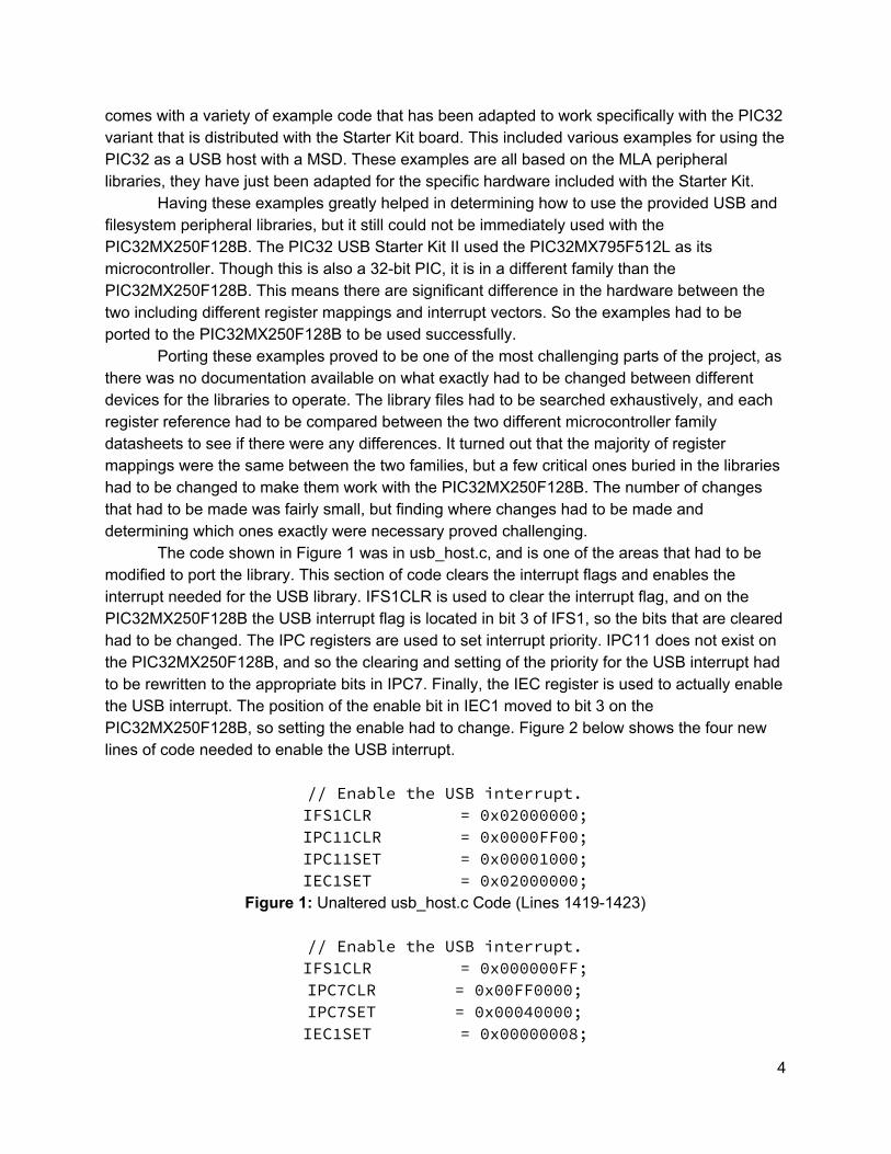
The code shown in Figure 1 was in usb_host.c, and is one of the areas that had to be modified to port the library. This section of code clears the interrupt flags and enables the interrupt needed for the USB library. IFS1CLR is used to clear the interrupt flag, and on the PIC32MX250F128B the USB interrupt flag is located in bit 3 of IFS1, so the bits that are cleared had to be changed. The IPC registers are used to set interrupt priority. IPC11 does not exist on the PIC32MX250F128B, and so the clearing and setting of the priority for the USB interrupt had to be rewritten to the appropriate bits in IPC7. Finally, the IEC register is used to actually enable the USB interrupt. The position of the enable bit in IEC1 moved to bit 3 on the PIC32MX250F128B, so setting the enable had to change. Figure 2 below shows the four new lines of code needed to enable the USB interrupt.
// Enable the USB interrupt. IFS1CLR = 0x02000000; IPC11CLR = 0x0000FF00; IPC11SET = 0x00001000; IEC1SET = 0x02000000;
Figure 1: Unaltered usb_host.c Code (Lines 1419-1423)
// Enable the USB interrupt. IFS1CLR = 0x000000FF; IPC7CLR = 0x00FF0000; IPC7SET = 0x00040000; IEC1SET = 0x00000008;
4

Figure 2: usb_host.c Interrupt Enable Code Altered for PIC32MX250F128B
Next, the interrupt vector for the USB interrupt had to be altered to fit the PIC32MX250F128B. The exact number of the interrupt vector changed between the two families of PICs, from 45 PIC32MX795F512L to 30 on the PIC32MX250F128B. Line 5176 in usb_host.c attached the interrupt to the vector, so this line had to be altered, from the original shown in Figure 3 to the new version shown in Figure 4.
#pragma interrupt _USB1Interrupt ipl4 vector 45 Figure 3: Unaltered usb_host.c Code (Line 5176)
#pragma interrupt _USB1Interrupt ipl4 vector 30
Figure 4: usb_host.c Interrupt Vector Code Altered for PIC32MX250F128B
Then one more small change had to be made to usb_host.c. Clearing the USB interrupt flag had to be changed in one more location, on line 5186. Figure 5 and Figure 6 below show the before and after for this line.
IFS1CLR = 0x02000000; Figure 5: Unaltered usb_host.c Code (Line 5186)
IFS1CLR = 0x000000FF;
Figure 6: usb_host.c Interrupt Flag Clearing Code Altered for PIC32MX250F128B
The configuration bits then had to be adjusted to work with the PIC32MX250F128B. The new configuration bits are listed in Figure 7 below. #pragma config UPLLEN = ON // USB PLL Enabled #pragma config FPLLMUL = MUL_20 // PLL Multiplier #pragma config UPLLIDIV = DIV_2 // USB PLL Input Divider #pragma config FPLLIDIV = DIV_2 // PLL Input Divider #pragma config FPLLODIV = DIV_2 // PLL Output Divider #pragma config FPBDIV = DIV_1 // Peripheral Clock divisor #pragma config FWDTEN = OFF // Watchdog Timer #pragma config WDTPS = PS1 // Watchdog Timer Postscale #pragma config FCKSM = CSDCMD // Clock Switching & Fail Safe Clock Monitor #pragma config OSCIOFNC = OFF // CLKO Enable #pragma config POSCMOD = HS // Primary Oscillator HS = high speed crystal #pragma config IESO = OFF // Internal/External Switch-over #pragma config FSOSCEN = OFF // Secondary Oscillator
5
Enable #pragma config FNOSC = PRIPLL // Oscillator Selection #pragma config CP = OFF // Code Protect #pragma config BWP = OFF // Boot Flash Write Protect #pragma config PWP = OFF // Program Flash Write Protect #pragma config ICESEL = ICS_PGx1 // ICE/ICD Comm Channel Select #pragma config DEBUG = OFF // Debugger Disabled
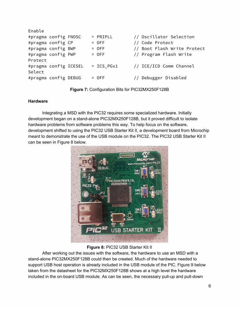
Figure 7: Configuration Bits for PIC32MX250F128B Hardware
Integrating a MSD with the PIC32 requires some specialized hardware. Initially development began on a stand-alone PIC32MX250F128B, but it proved difficult to isolate hardware problems from software problems this way. To help focus on the software, development shifted to using the PIC32 USB Starter Kit II, a development board from Microchip meant to demonstrate the use of the USB module on the PIC32. The PIC32 USB Starter Kit II can be seen in Figure 8 below.
Figure 8: PIC32 USB Starter Kit II
After working out the issues with the software, the hardware to use an MSD with a stand-alone PIC32MX250F128B could then be created. Much of the hardware needed to support USB host operation is already included in the USB module of the PIC. Figure 9 below taken from the datasheet for the PIC32MX250F128B shows at a high level the hardware included in the on-board USB module. As can be seen, the necessary pull-up and pull-down
6

resistors are included as well as the transceivers. The most important missing piece of hardware is the actual plug for a MSD itself, but various breakout boards exist for USB-A female connectors that can be used for this. This project used this breakout from Sparkfun: https://www.sparkfun.com/products/12700.
Figure 9: USB Module Hardware
7
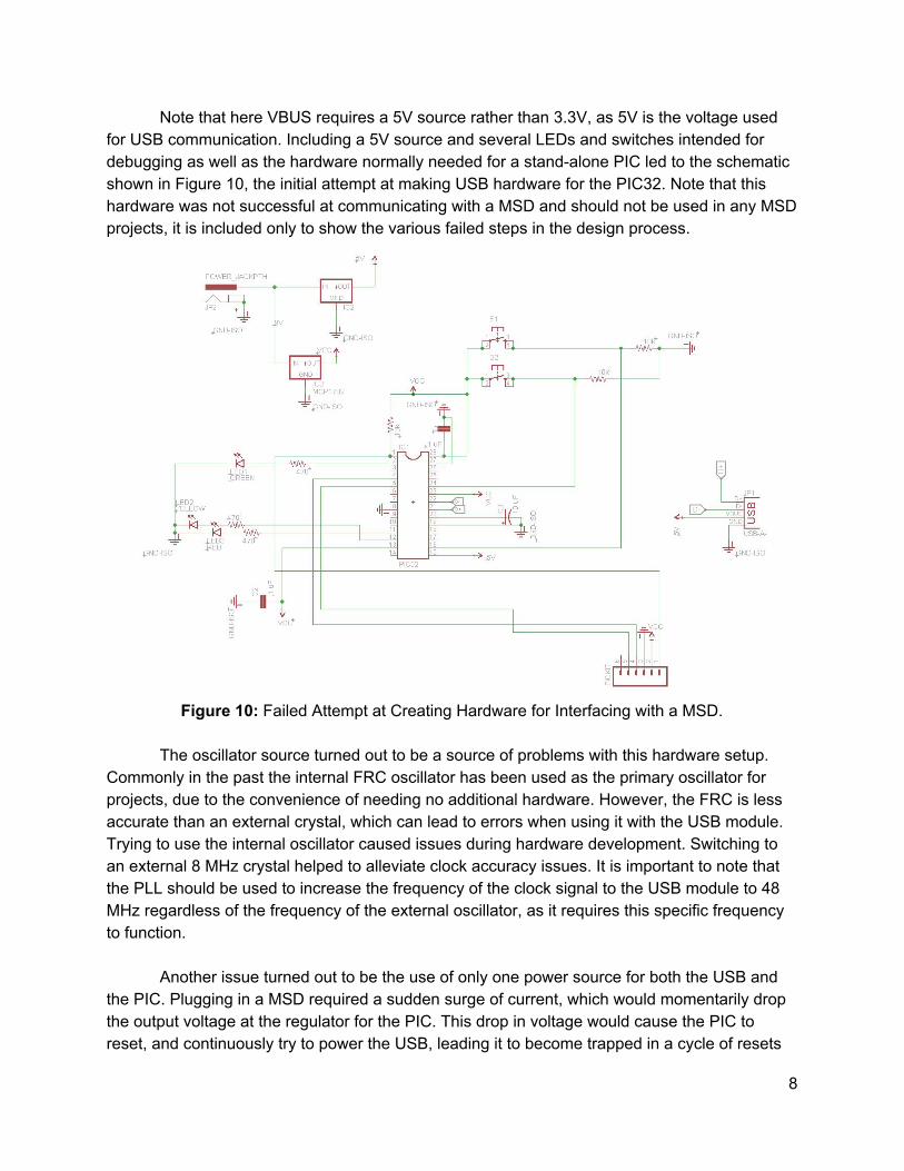
Note that here VBUS requires a 5V source rather than 3.3V, as 5V is the voltage used for USB communication. Including a 5V source and several LEDs and switches intended for debugging as well as the hardware normally needed for a stand-alone PIC led to the schematic shown in Figure 10, the initial attempt at making USB hardware for the PIC32. Note that this hardware was not successful at communicating with a MSD and should not be used in any MSD projects, it is included only to show the various failed steps in the design process.
Figure 10: Failed Attempt at Creating Hardware for Interfacing with a MSD.
The oscillator source turned out to be a source of problems with this hardware setup.
Commonly in the past the internal FRC oscillator has been used as the primary oscillator for projects, due to the convenience of needing no additional hardware. However, the FRC is less accurate than an external crystal, which can lead to errors when using it with the USB module. Trying to use the internal oscillator caused issues during hardware development. Switching to an external 8 MHz crystal helped to alleviate clock accuracy issues. It is important to note that the PLL should be used to increase the frequency of the clock signal to the USB module to 48 MHz regardless of the frequency of the external oscillator, as it requires this specific frequency to function.
Another issue turned out to be the use of only one power source for both the USB and
the PIC. Plugging in a MSD required a sudden surge of current, which would momentarily drop the output voltage at the regulator for the PIC. This drop in voltage would cause the PIC to reset, and continuously try to power the USB, leading it to become trapped in a cycle of resets
8

when an MSD was plugged in. Adding a separate power source for the USB bus resolved this issue. Figure 11 below shows the final, functional circuit for interfacing with an MSD that includes the modifications mentioned previously.
Figure 11: Functional Circuit for Interfacing Standalone PIC32 with MSD
Use of the Library
How to Create a MSD Project
To create a new project it is recommended that the zip file containing the example projects be downloaded. This file contains a project called USB_MSD_Base which contains all necessary files needed to run a USB mass storage device project. In this project the main file can be modified as needed, however none of the code that is initially in the main file should be removed as it is necessary to run USB projects. It is suggested to use this USB_MSD_Base project since it already has all the various include paths to the needed libraries setup. Configuring these includes paths is possible for a newly created project, but can be time-consuming and difficult. Either using USB_MSD_Base or a renamed copy of it to start a project means that all configuration of the includes paths will already be handled. The various example projects can be deleted if desired but certain folders and files in the
9

PIC32-Mass-Storage folder must be kept. FSconfig.c, HardwareProfile.h, usb_config.c, usb_config.h, and the entire Microchip folder must not be deleted.
To create a completely new project first download the zip file with the example projects. The necessary files are in the PIC32-Mass-Storage folder. For a USB project the entire Microchip folder, FSconfig.c, HardwareProfile.h, usb_config.c, and usb_config.h are all needed. The necessary include statements and the include path for these files will also need to be set up in the new project. Creating a new project like this is not recommended as including the various files correctly can be troublesome. Hardware for Using the USB
This subsection is intended to specify the hardware needed to use a MSD with the PIC32 as well as the specific hardware used for the example code setups. For more information on how the hardware for the USB was designed, refer to the Hardware subsection of the Design Process section.
Minimal Circuit Below is the minimal circuit for using the PIC32MX250F128B stand-alone and
incorporating a PICKIT3 for programming and debugging. Note that there are two separate power sources, one that provides 3.3 V to power the PIC and one that provides 5 V to power the USB bus. It is critical that there be two separate power sources to prevent current surges on the USB bus from causing resets on the PIC. There is also an external 8 MHz oscillator that should be set as the primary oscillator for the PIC. The internal FRC oscillator should not be used, as its lower accuracy can cause erratic behavior. A USB Type-A Female connector is also required. Various breakouts for this connector are available, such as this model from Sparkfun: https://www.sparkfun.com/products/12700 . The other resistors and capacitors are required for the PIC to run stand-alone and are not specific to using the USB module.
10

Figure 12: Minimal USB Circuit for Stand-alone PIC32 Using PICKIT 3
Example Code Circuit
Below is the circuit used to run the example code. Note that it includes several LEDs to indicate the status of the programs, buttons for user input, and a connection through an FTDI serial cable to a computer to provide serial output to a terminal such as PuTTY. For more information on the serial connection and the setup for the terminal used, refer to Bruce Land’s page on the topic here.
11

Figure 13: USB Circuit Used for Example Code
Using the USB Stack
Communicating with the USB device is handled by a Microchip library. Details about how this library works can be found on Microchip’s documentation (AN1140). Before doing anything involving USB communication the function USBInitialize should be called with an argument of 0. This function will initialize the USB stack so that USB communication can occur. The USB communication is run by using a state machine where transitions are driven by various events on the USB bus. The state machine is shown in Figure 14 although detailed knowledge of its workings is not required for manipulating files on a USB flash drive. The state machine is advanced by continuously calling the USBTasks function. This function should be called frequently and repeatedly, or the USB library will not be able to function.
Events are handled in USB_ApplicationEventHandler which can be found inside the example code files, where there are several different events checked for. EVENT_VBUS_REQUEST_POWER happens when the connected USB device requests power which occurs when the device is first connected. EVENT_VBUS_RELEASE_POWER happens when the device turns off the bus power which occurs when the device disconnects. Code can be put in these case statements in order to have additional functionality when a USB is
12

connected or disconnected. The rest of the event are various types of errors and code to handle these errors can be inserted as desired, though it is not required.
The event handler is not automatically entered when an event occurs. To enter the handler the function USBTasks must be called. This function will handle events and update the USB stack state machine and so should be called often in a loop.
To check if a USB device is attached a flag can be set when EVENT_VBUS_REQUEST_POWER occurs or alternatively USBHostMSDSCSIMediaDetect can be called which will return 1 if a device is detected. It can be checked if a device is disconnected by setting or clearing a flag when EVENT_VBUS_RELEASE_POWER occurs.
The pieces of example code can be helpful in understanding how to handle connecting and disconnecting USB devices as they demonstrate how to drive a program through connecting and disconnecting a USB flash drive.
Figure 14: USB State Machine
13

Using the Filesystem Library Microchip provides a library for reading, writing, and modifying files on a USB flash
drives and several other memory storage devices. The filesystem library is included in the PIC32 code and can be helpful for manipulating files on a flash drive using a PIC32. Microchip’s documentation on the library can be found here and the functions it contains are listed in Table 1 which comes from the documentation. It is highly recommended to read Microchip’s documentation as it goes into more detail on the filesystem library.
To use the filesystem library a USB flash drive must be connected to the PIC first. Once it is successfully connected and detected by the PIC the FSInit function should be called which will initialize the library and check if the connected USB device is compatible. If initialization is successful the function will return 1, otherwise 0 is returned.
Directories on the drive can be created, removed, or changed using the FSmkdir, FSchdir, and FSrmdir functions. These functions require the directory being manipulated to be specified using strings of characters in combination with directory names. A ‘\\’ refers to the top level root directory, ‘.’ refers to the current directory, and ‘..’ refers to the previous directory. When entering a path to a directory names should be separated by “\\” e.g. “NAME1//NAME2//NAME3” to refer to the NAME3 directory which is in the NAME2 directory which is in the NAME1 directory. A list of example directory path strings can be found in Table 2 which can also be found in the Microchip documentation. The name of the current directory can be returned using the FSgetcwd function.
Directories and files can be searched for using FindFirst and FindNext which return a pointer to a structure containing information about the file that is found. Table 3 which can also be found in the Microchip documentation shows the format of this structure.
To begin manipulating a file the file must first be opened using the FSfopen function which returns a pointer to an FSFILE structure which many other functions use to specify what file they should read or write from. FSfopen takes in a string with the name of the file as its argument and has the restriction that the file name before the period be fewer than eight characters long and extension after the period be three or fewer characters long. Once a file has been opened it can be manipulated using various other functions. Files can be opened in one of three modes read (‘r’), write (‘w’), and append (‘a’). In write mode the data in the file will be lost and completely overwritten. If a file does not exist, attempting to open it in write mode will create it. When a file is opened in append mode the data in the file is not lost and the data in the file can be modified. By default writing will begin from the end of the file in this mode so data will be appended but parts of the file can be overwritten in this mode if desired. Attempting to open a nonexistent file in this mode will create it. Files opened in append or write mode cannot be read. In order to read a file it should be opened in read mode. In read mode files cannot be written.
When files are open they are put in the heap and kept there until the file is closed using FSfclose. It is important to close files when finished using them as this will free up memory and update file information. All files should be closed before removing a flash drive in order to ensure that the file is not corrupted and is written correctly.
Once a file has been opened in append or write mode it can be written to using the FSfwrite function. These functions begin writing to the file starting from the position of a “file
14

pointer”. By default the file pointer is at the beginning of the file when opening in write mode and the end of the file when opening in append mode. The position of this pointer can be moved using the FSfseek function which allows writing to happen at different points in the file. The function FSftell returns the current position of the file pointer which can also be helpful. FSfrewind returns the file pointer’s position back to the beginning of the file.
When a file is opened in read mode it can be read using the FSfread function. This function begins reading from the position of the file pointer and moves the file pointer to the end of the read data. If reading is repeatedly done the entire file will eventually be read and the file pointer will move to the end of the file. When the end of the file is reached FSfread will return a 0. FSfeof can also be used to check if the file pointer has reached the end of a file and returns 1 if this has occurred. More detail on all of the filesystem functions and their usage can be found in the Microchip documentation (AN1045).
Function Name Description
FSInit This function initializes the card, loads the master boot record (partition information), loads the boot sector and updates the parameters passed into it with information from each of these.
FSfclose This function updates the file information, writes the rest of the entry in and frees the RAM from the heap that was used to hold the information about that file. This function will also update time-stamp information for the file.
FSfeof This function detects if the end of the file has been reached.
FSfopen This function allocates space in the heap for file information. If the file being opened already exists, FSfopen can open it so data will be appended on the end of the file, erase it and create a new file with the same name to be written to, or simply open it for reading. If the file does not exist, FSfopen can create it. This function then returns a pointer to the structure in the heap that contains information for this file.
FSfopenpgm This function opens a file on the SD card and associates an FSFILE structure (stream) with it using arguments specified in ROM. This
15

function is only necessary on the PIC18 architecture.
FSfread This function will read information from an open file to a buffer. The number of bytes written can be specified by its parameters. If FSfread is called consecutively on the same open file, the read will continue from the place it stopped after the previous read. This function will return the number of data objects read.
FSfseek This function changes the position in a file. When a user calls FSfseek, they specify the base address to set, which can either be at the beginning or end of the file, or at the current position in the file. The user also specifies an offset to add to the base (note that if the base address is at the end of the file, the offset will be subtracted). So, if fseek is called FSfseek with the base set to the beginning of the file, and a specified offset of ‘0’, the position would be changed to the first byte of the file.
FSftell This function returns the current position in the file. The first position in the file is the first byte in the first sector of the first cluster which has the value ‘0’. So, if a file was created and 2000 bytes were written to it, FSftell would return the number 1999 if it was called.
FSfwrite This function writes information from a buffer to an open file. The algorithm it uses reads a sector from the data region of the disk to SRAM, modifies the relevant bytes and then writes the sector back to the disk. Because each FSfwrite call reads the data first, the ability to open multiple files at a time is supported. This also means that writing data in larger blocks will take less time than writing the same amount of data in smaller blocks, since fewer sector reads and writes will be needed.
FSremove This function searches for a file based on a file name parameter passed into it. If the file
16
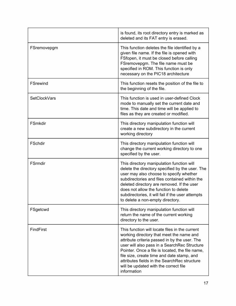
is found, its root directory entry is marked as deleted and its FAT entry is erased.
FSremovepgm This function deletes the file identified by a given file name. If the file is opened with FSfopen, it must be closed before calling FSremovepgm. The file name must be specified in ROM. This function is only necessary on the PIC18 architecture
FSrewind This function resets the position of the file to the beginning of the file.
SetClockVars This function is used in user-defined Clock mode to manually set the current date and time. This date and time will be applied to files as they are created or modified.
FSmkdir This directory manipulation function will create a new subdirectory in the current working directory
FSchdir This directory manipulation function will change the current working directory to one specified by the user.
FSrmdir This directory manipulation function will delete the directory specified by the user. The user may also choose to specify whether subdirectories and files contained within the deleted directory are removed. If the user does not allow the function to delete subdirectories, it will fail if the user attempts to delete a non-empty directory.
FSgetcwd This directory manipulation function will return the name of the current working directory to the user.
FindFirst This function will locate files in the current working directory that meet the name and attribute criteria passed in by the user. The user will also pass in a SearchRec Structure Pointer. Once a file is located, the file name, file size, create time and date stamp, and attributes fields in the SearchRec structure will be updated with the correct file information
17

FindFirstpgm This function operates in the same manner as the FindFirst function, except the name criteria for the file to be found will be passed into the function in ROM. This function is only necessary on the PIC18 architecture.
FindNext This function will locate the next file in the current working directory that matches the criteria specified in the last call of FindFirst or FindFirstpgm. It will then update the SearchRec structure provided by the user with the file information
FSformat This function will erase the root directory and file allocation table of a card. The user may also call the function in a mode that will cause it to create a new boot sector based on the information in the master boot record.
FSfprintf This function will write a formatted string to a file. This function will automatically replace any format specifiers in the string passed in by the user with dynamic values from variables passed into the function.
Table 1: List of FileSystem Library Functions
Path Meaning
"\\" The root directory
"." Current directory
".." Previous directory
"ONE" Directory ONE in the current directory
".\\ONE" Directory ONE in the current directory
"\\ONE" Directory ONE in the root directory
"..\\ONE" Directory ONE in the previous directory
"ONE\\TWO" Directory TWO in directory ONE in the current directory
"\\ONE\\TWO" Directory TWO in directory ONE in the root
18

directory
"ONE\\..\\TWO" Directories ONE and TWO in the current directory (this path could be used to create non-existent directories in the same place using the FATmkdir function)
Table 2: Example Directory Path Strings
Element Function
char file name The name of the file (null-terminated)
unsigned char attributes The file attributes
unsigned long file size The size of the file in bytes
unsigned long time-stamp The create time and date of the file
Bits Value
31:25 Year (0 = 1980, 1 = 1981, ...)
24:21 Month (1 = Jan, 12 = Dec)
20:16 Day (1-31)
15:11 Hours (0-23)
10:5 Minutes (0-59)
4:0 (Seconds/2) (0-29)
Table 3: Contents of the SearchRec Structure Examples
File_Write_Demo The File_Write_Demo project shows how to create a file and how to write text to a file.
The project begins by setting up the UART interface so that the program can display what is happening. Next a device attached flag is declared so that the program can perform differently depending on whether or not a device is plugged in. Finally USBInitialize is called which sets up the USB stack. This must be called before any USB interactions can take place. A yellow LED is turned on at the same time to signal that the device is ready to have a USB flash drive plugged in.
A while loop is entered where the main body of the program runs. In this loop USBTasks is called first which updates the USB state machine and handles USB events and tasks. This
19

function must be called every loop to continually handle USB operations such as detecting when a device is plugged in or removed. The handler for USB tasks can be found at the end of the main file in USB_ApplicationEventHandler . This event handler has various states listed where the program can perform different functions based on the state. In this program only the EVENT_VBUS_RELEASE_POWER event does anything. This event happens when the USB device is unplugged and when this happens the device attached flag is cleared.
When a USB device is plugged in and detected USBHostMSDSCSIMediaDetect begins to return true which allows the program to begin writing after a flash drive is inserted. When the flash drive is detected the red LED is turned on to signal that writing has begun. The filesystem is then initialized using FSInit which returns true if initialization is successful. This function must be called before filesystem manipulation can be done. The program then prints that it is writing to the console. The program begins writing by opening the file in write mode using FSfopen . The first argument of this function is the file name which and the second is the mode the file will be opened in. The second argument is a ‘w’ which opens the file in write mode. When ‘w’ is used the file will be created and then opened in write mode if no file with the name entered exists or the existing file with the same name will be completely cleared and writing can be done as if it were a blank file. A pointer to the opened file is passed to the variable myFile which is used in other functions to specify writes or reads are being done with this file.
Once the file has been opened it is written using FSfwrite . This function takes in a pointer to the data that will be written as its first argument. In this program the data is a string. The next two arguments specify the amount of data to be written. The second argument specifies the length of the item being written in bytes while the third specifies how many items are being written. The two multiplied together must equal the length of whatever data is being written. In this program the second argument is one as each char is one byte and the third argument is the length of the string as that many chars will be written. The final argument is the file that will be written which in this case is myFile .
Once the writing is complete the program prints that the write has completed and the file is closed using FSfclose which takes in the file that will be closed. In order to complete the write without risking data being corrupted or other errors files should be closed when reading or writing is finished. After the file is closed the green LED is turned on and the red LED turned off to signal that it is safe to remove the flash drive. The program then waits in a loop where USBTasks is repeatedly called which will handle the event where the USB device is removed and will cause the loop to exit. The green LED is then turned off to signal that the device was removed and the program loops to begin again.
File_Read_Demo The File_Read_Demo project reads a file and prints it through the UART interface. The
file it reads by default should be named File.txt which is case insensitive. Other files can be read by changing the definition of FileName on line 23 or by changing the first argument to the FSfopen function on line 124. The program is setup to read a 1800 bytes or less long file but this is a limitation of the specific program and not the USB interface. 1800 bytes was chosen to limit memory usage as the program reads the entire file into a buffer before displaying it. This
20
could be worked around by reading and displaying part of the file at a time or by increasing the buffer size.
File_Read_Demo works in the same way as File_Write_Demo when connecting and disconnecting the USB device. The section on File_Write_Demo gives details on these operations.
When File_Read_Demo opens the file it uses FSfopen but the second argument is ‘r’ in order to open the file in read mode. When the file is in read mode it cannot be written but can instead be read. Once the file is open a buffer is created in order to hold the contents of the file. This buffer is cleared beforehand to ensure there is no extra data inside before reading.
Once the buffer is cleared the file is read using FSfread which reads data out of the file and returns a 0 if the end of the file is reached. As data is read from the file a “file pointer” is moved to the end of the read data. Each read begins from the location of the file pointer. This allows repeated reads to eventually read all of the data in the file by moving the file cursor to the end of the file. Reading continues until the FSfread returns a zero signalling the end of the file was reached or until the buffer is full and can’t store more data.
The FSfread function takes in four arguments. The first is a pointer to where the data from the file should be stored. In this program the data is put into a temporary char, temp , which then moves the data into the buffer. The next two arguments are used to determine how much data is read. The first argument is the length of the item to be read and the second is the number of item to read. The two arguments multiplied together should be the same size as the data being read in bytes. In this program both the arguments are one as chars are one byte long and they are being read out one char at a time. The final argument is the file being read which is what FSfopen returns.
Once all data has been put in the buffer or the buffer becomes full it is read out through UART using printf statements. After this is done the file is closed using FSfclose. Files should be closed after reading or writing them as data can become corrupted if files are left open.
File_Seek_Demo File_Seek_Demo writes a short phrase to the middle of an existing file. It demonstrates
how to move a “file pointer” in order to be able to write or read from specific points in a file as well as how to write to an existing file without deleting all the data it already holds. The program overwrites bytes 20 to 25 of a text file and changes them to show “PIC32” instead. Existing files used with this demo should be at least 20 bytes long. To use a file with this demo place it in the root directory of a flash drive and rename it “seek.txt” or place it in the root directory. Alternatively, the file can be placed in the root directory and then the first argument of FSfwrite on line 125 can be changed to match the file name.
File_Seek_Demo works in the same way as File_Write_Demo when connecting and disconnecting the USB device. The section on File_Write_Demo gives details on these operations.
When a USB device is connected the file is opened in append mode using FSfopen. The first argument is the name of the file to be opened and the second argument is ‘a’ which specifies the file should be opened in append mode. Append mode differs from write mode
21
because it modifies the existing file only changing some of the data while write mode will completely overwrite an existing file deleting all previous data. The file cannot be read in append mode.
Once the file has been opened a “file pointer” is moved which changes where writing or reading will begin from in the file. This is done by using FSfseek . The first argument of FSfseek specifies which file the file pointer is being moved in. The second argument specifies how far the file pointer should be moved in bytes. In this program the pointer is moved 20 bytes forward in order to begin writing 20 bytes into the file. The final argument specifies where the pointer should be moved from. SEEK_SET means the beginning of the file, SEEK_CUR means the current location of the file pointer, and SEEK_END means the end of the file. This program starts from the beginning of the file and moves 20 bytes forward.
Once the file pointer has been moved the file is then written using FSfwrite . This function is set to write “PIC32” starting at the file pointer and then replacing the next five bytes. This causes bytes 20-25 to become “PIC32”.
After the write is complete the file is closed using FSfclose . Files should be closed after reading or writing them as data can become corrupted if files are left open.
File_CSV_Write File_CSV_Write creates a comma separated values (CSV) file to demonstrate that files
other than text files can be written using the PIC32. The program also demonstrates doing multiple write operations before closing a file. CSV files create a table where each value in a column is separated by a comma and each row is separated by a newline character.
File_CSV_Write works in the same way as File_Write_Demo when connecting and disconnecting the USB device. The section on File_Write_Demo gives details on these operations.
Once a USB device is connected the program opens and creates a file in write mode “OW.csv” using the FSfwrite function. Once the file is opened csvRow is called which writes a single row of the CSV file table. It does this by using FSfwrite to write a value and then using it again to write a comma to the file. This is done four times and then the final value is written followed by a newline character. This creates a pattern in the file that looks like val1, val2, val3, val4, val5\n where \n is a newline character. csvRow is called five times in order to create five rows in the table.
Once the five rows have been written to the file the file is closed using FSfclose . Files should be closed after reading or writing them as data can become corrupted if files are left open. The USB can be removed and the files can be viewed in a table format using programs such as Microsoft Excel.
References and Acknowledgements
Microchip Filesystem Library Documentation http://ww1.microchip.com/downloads/en/AppNotes/USB_Host_Stack_01140a.pdf
22

Microchip USB Mass Storage Class on Embedded Device Documentation http://ww1.microchip.com/downloads/en/AppNotes/01169a.pdf PIC32 Datasheet http://people.ece.cornell.edu/land/courses/ece4760/PIC32/Microchip_stuff/2xx_datasheet.pdf Bruce Land’s UART Serial Communication for the PIC32 http://people.ece.cornell.edu/land/courses/ece4760/PIC32/index_UART.html Microchip Libraries for Applications http://www.microchip.com/mplab/microchip-libraries-for-applications MPLAB Harmony http://www.microchip.com/mplab/mplab-harmony PIC32 USB Starter Kit http://www.microchip.com/DevelopmentTools/ProductDetails.aspx?PartNO=DM320003-2 USB Type-A Female Connector https://www.sparkfun.com/products/12700 Thanks to Professor Land for telling us about this project and his help with it.
23