Using Information From Relays to Improve the Power … · · 2016-01-221 Using Information From...
14
Using Information From Relays to Improve the Power System – Revisited David Dolezilek Schweitzer Engineering Laboratories, Inc. Presented at GRIDTECH 2011 New Delhi, India April 19–21, 2011 Previously presented at the Southern African Power System Protection Conference, November 2010 Previously published in SEL Journal of Reliable Power, Volume 1, Number 2, October 2010 Previous revised editions released December 2010 and August 2010 Originally presented at the 1st Annual Protection, Automation and Control World Conference, June 2010
Transcript of Using Information From Relays to Improve the Power … · · 2016-01-221 Using Information From...

Using Information From Relays to Improve the Power System – Revisited
David Dolezilek Schweitzer Engineering Laboratories, Inc.
Presented at GRIDTECH 2011 New Delhi, India April 19–21, 2011
Previously presented at the Southern African Power System Protection Conference, November 2010
Previously published in SEL Journal of Reliable Power, Volume 1, Number 2, October 2010
Previous revised editions released December 2010 and August 2010
Originally presented at the 1st Annual Protection, Automation and Control World Conference, June 2010

1
Using Information From Relays to Improve the Power System – Revisited
David Dolezilek, Schweitzer Engineering Laboratories, Inc.
Abstract—Ten years ago, engineers began considering Ethernet for use in substation system integration. However, it had several characteristics that made it unsuitable for near real-time supervisory control and data acquisition (SCADA) and peer-to-peer communications. This paper describes the improvements that have been deployed over the last decade and the effect these improvements have had on speed, dependability, and determinism of messaging over Ethernet. SCADA, engineering access, and peer-to-peer communications have all been improved via new methods specific to the power industry, as well as others developed to improve Ethernet in general.
The 1998 technical paper “Using Information From Relays to Improve the Power System” explained the wealth of information available from protective relay intelligent electronic devices (IEDs), discussing information categories and methods available to retrieve data. It also compared the performance of peer-to-peer protocol message delivery based on the device address with multicast Utility Communications Architecture (UCA) Generic Object-Oriented Substation Event (GOOSE) messages based on the network address. Revisiting the analysis shows how IEC 61850 GOOSE messages make use of recent IEEE and IEC Ethernet enhancements and benefit from the replacement of Ethernet hubs with store-and-forward switches.
Two major differences between messaging based on a network address versus a device address impact the design, performance, diagnostics, and upgrade of communications systems. Unlike direct serial channels, the physical path of Ethernet network messages does not match the logical path. Ethernet messages that logically pass directly between two peers actually physically pass through several cables and switches. Further, the physical path changes over time without the knowledge of the peers. Because several GOOSE sources and destinations (and, in fact, several different protocols) all share bandwidth on the IED Ethernet interface, it is not evident which IEDs are publishing or subscribing to each other. This paper explains the methods for determining active peers and their messaging statuses in order to support commissioning and diagnostics. Perhaps equally important is the use of these methods by a technician who wishes to take a relay out of service but no longer has physical terminations or wiring diagrams and wishes to disable only one of several logical connections within one physical Ethernet connection.
Adding IEDs to an existing network requires new methods of identifying existing communications behavior, changing the behavior, and being certain that it was changed correctly. IEC 61850 GOOSE messages provide virtual wiring terminations among IEDs. Therefore, each new message configuration may actually change these interconnections. This paper discusses the enhancements made to Ethernet network mechanisms and message construction that improve the likelihood that substation Ethernet local-area networks (LANs) will provide satisfactory performance, determinism, and availability. These networks are being considered not only for convenient engineering access but also for new and more mission-critical SCADA and wide-area automation systems based on synchronous communication, like
synchrophasors. Also, many new uses for multicast messaging, including GOOSE and Sampled Value (SV), are being considered for substation and distribution automation and protection once a mission-critical LAN is available.
Protection and communications engineers alike can review the enhancements made to substation Ethernet networking over the last decade to understand the state of the art and appropriate design considerations. In order to effectively use the available IED features for protection and automation, protection and automation engineers must understand how to create communications networks capable of constant, synchronous, and deterministic messaging.
I. INTRODUCTION Modern microprocessor-based relays are no longer merely
protection devices for power apparatus but have evolved to perform many other functions that facilitate effective power system operation. Contemporary microprocessor-based relays routinely include metering, protection, automation, control, digital fault recording, and reporting applications. Because of this, it is now more accurate to refer to these microprocessor-based devices as multifunction intelligent electronic devices (IEDs). As IEDs replace old electromechanical relays in new and retrofitted power substations, the amount of data available from substations increases exponentially [1].
To accommodate new, increasingly popular IED network functions, substation communications infrastructure is experiencing a dramatic change and is migrating to Ethernet. The majority of successful substation integration systems that are going into service today and in the near future are based on non-Ethernet local-area networks (LANs), built using EIA-232 point-to-point and EIA-485 multidrop communications ports within the IEDs. The information exchanges are carried out using register and/or address-based protocols, such as DNP3, IEC 60870, and Modbus®. These communications methods also include National Institute of Standards and Technology-approved protocol standards created by a standards-related organization (SRO) and offered via a “reasonable and nondiscriminatory” license. This includes MIRRORED BITS® communications, open vendor-developed serial protocols, and other standards, such as IEEE C37.94. With the new IEC 61850 standard and the popularity of Ethernet networks, the entire picture of substation communication is changing.
Today, the IEC 61850 standard is gaining popularity in utilities. Many substation integration and automation projects are built demonstrating the benefits of the standard [2].
In addition to many client/server substation integration, automation, and control functions, the IEC 61850 standard

2
includes two real-time, peer-to-peer communications methods that are particularly useful to protection and automation engineers: Generic Substation Event (GSE) messaging and Sampled Value (SV) messaging. The two types of GSE messages, Generic Object-Oriented Substation Event (GOOSE) and Generic Substation State Event (GSSE), can coexist but are not compatible. GSSE is an older, binary-only message type, and all new systems use the more flexible but less efficient GOOSE, which conveys both binary and analog data. When applied with precision, these peer-to-peer communications mechanisms allow protection engineers to revolutionize traditional protection and control schemes, reducing the cost of system design, installation, commissioning, operation, and maintenance, and increasing the reliability of the system at the same time.
SV peer-to-peer messaging is used to pass digitized transducer signals from switchyards to IEDs via communications cables instead of copper conductors. Like GSE, IEC 61850-compliant SV messages are multicast, so data measured at one location are sent to any number of subscribers throughout the Ethernet network. SV is an important IEC 61850 messaging protocol that ensures multivendor interoperability when implemented according to the standard. SV applications will benefit from the enhancements to GOOSE multicast message management that are detailed in this paper. Both GOOSE and SV messaging act as virtual cables to move measured and calculated data to other system locations via digital communication instead of copper conductors. Their contents act as virtual wires within the virtual cables to transfer values from place to place.
With the new IEC 61850 standard, communications standards and protocols are no longer used only by substation integration engineers for asynchronous data flow, like supervisory control and data acquisition (SCADA), engineering access, and metering. To effectively use the available IED features for protection and automation, protection and automation engineers must understand how to create communications networks capable of constant, synchronous, and deterministic messaging. Protection, control, and automation engineers need to understand the mechanisms involved in GOOSE and SV messages (i.e., creation, publication, and subscription), as well as the parameters of the communications networks that transmit the messages. Using this information, protection, control, and automation engineers can influence the performance of GOOSE and SV messages and therefore the speed, jitter, security, and dependability that affect protection schemes. They must accurately specify the intrasubstation LANs or intersubstation wide-area networks (WANs) to guarantee the reliable operation of protection and automation schemes.
In this paper, we concentrate on the industry-wide efforts made over the last decade to improve the likelihood that Ethernet networks will satisfy local- and wide-area protection, control, and monitoring (PCM).
II. ENHANCEMENT 1: CREATE A NORTH AMERICAN COMMUNICATIONS STANDARD
During the 1990s, worldwide electric utility deregulation expanded, “creating demands to integrate, consolidate, and disseminate real-time information quickly and accurately within and with substations” [3]. Traditional SCADA vendors continued to adhere to the business model of customer retention via closed systems using private and proprietary communications protocols. On the other hand, North American IED vendors, primarily protective relay manufacturers, recognized the need to develop standardized methods to share information among a network of interconnected devices. The field-proven success of serially connected, multivendor IED LANs in North America demonstrated clear advantages over centralized SCADA methods.
PCM IEDs are multifunction devices that perform PCM functions first and foremost but also serve as sources of information. As these IEDs acquire power system data and perform additional calculations and logic, they create a specific local database with knowledge about the power system asset with which they are associated. Therefore, in addition to present power system values, these IEDs record information about the health, performance, and history of the overall power system, as well as specific assets, such as transformers, breakers, and other primary equipment. Time-synchronized measurements available in modern IEDs enable new applications based on time-aligned data sharing across wide areas among IEDs and data client applications.
Because mission-critical power system applications require both robust components and deterministic behavior, PCM IEDs are designed to perform processes in real time. Processor, memory, operating system, and circuit board design decisions are made with knowledge of the real-time deadlines of protection and control applications. Once these processes are optimized, less time-critical monitoring applications are carefully added to the IED so as not to impede the mission-critical real-time activities. Robustly designed PCM IEDs appropriately perform all applications, such as simultaneous protection, control, and phasor measurement.
As microprocessor-based relays integrated multiple functions into one physical device, many communications protocols were developed to integrate virtually thousands of pieces of information from each IED. These protocols include both SRO protocols and independent standards, such as IEC 60870 and DNP3, managed by a committee (users group) funded by a collection of vendors and users that organize enhancements and testing.
Many protocols of both varieties can coexist on an IED network to collectively serve several different functions. However, complex combinations of protocols make designing an overall substation automation system (SAS) to integrate information from devices of different manufacturers a
3
daunting task. Especially important is the task of integrating or isolating protection communication, which needs to be well understood by the protection engineer, as well as the network communications architect.
The mature and massive ten-part IEC 61850 communications standard grew from the Utility Communications Architecture (UCA) effort to standardize SCADA communications. More than two decades ago, the Electric Power Research Institute (EPRI) commissioned the UCA project, which identified the requirements, overall structure, and specific communications technologies and layers to implement an interoperable SCADA protocol. By 1994, EPRI had recognized the importance of tying substation control equipment and power apparatus into the UCA scheme but had not defined a particular approach. Next, they launched Research Project 3599 to define, demonstrate, and promote an industry-wide UCA-compatible communications approach for substations. This work led to the 1999 IEEE Technical Report 1550, a suite of international standards.
III. ENHANCEMENT 2: STANDARDIZE DATA DESCRIPTIONS AND ORGANIZATION
UCA differed from previous utility protocols by its use of object models of devices and device components. UCA2 for field devices defined the Generic Object Model for Substation and Feeder Equipment (GOMSFE) for IEDs within the substation. This model defines common data formats, identifiers, and controls for substation and feeder devices, such as switches, voltage regulators, and relays [4]. This method enabled the use of simple, object-oriented database techniques and a familiar method of data organization for engineers who use other industry-standard databases.
Metadata, such as names and formats of values being published, are used to simplify the configuration process. These same metadata are used in real time to perform online verification of the real-time communication and IED configuration. This self-description of data emulates SRO protocol methods and significantly reduces the cost of data management and downtime due to configuration errors.
IV. ENHANCEMENT 3: STANDARDIZE THE USE OF IEEE 802.3 CARRIER SENSE MULTIPLE ACCESS/COLLISION DETECTION
(CSMA/CD) ETHERNET FOR CONNECTIVITY AND TRANSPORT The methods for message transport applied in UCA, like
Ethernet, Transmission Control Protocol/Internet Protocol (TCP/IP), and Manufacturing Message Specification (MMS), defined the exchange of near real-time data and metadata. Ethernet was chosen to emulate previous SRO serial protocol methods to allow multiple protocols to coexist on the same network. TCP/IP was chosen to enhance the likelihood that asynchronous communications exchanges like SCADA and engineering access would recover from lost messages and failed connections. MMS client/server methods were chosen to emulate previous SRO protocol methods that allow multiple clients access to centralized data aggregation instead of the more traditional one-to-one master/slave SCADA methods.
Telnet was identified as a virtual terminal engineering access method that could coexist on the same shared bandwidth Ethernet connection as MMS traffic.
Ethernet technology emerged in the 1970s with the initial objective of connecting office computers and printers. Ethernet makes use of the Open Systems Interconnection (OSI) Reference Model, which allocates the communications functions. The International Organization for Standardization (ISO) created the OSI Reference Model to define standardized methods for computers to communicate over networks [4]. The OSI Reference Model is a conceptual reference that breaks the communications process into seven different layers. Each layer provides a small set of specific services to the layer below and the layer above, which provides independence. The functions of a specific layer can be modified without changing the overall structure of the model. The protocols defined at each layer establish a peer-to-peer relationship with the corresponding layer of the receiving device. The UCA-referenced ISO/IEC 8802.3 and IEEE 802.3 CSMA/CD specifications define Ethernet to be a subset of the OSI Reference Model. The layers of the OSI Reference Model are as follows:
1. Physical – converts bits into signals for outgoing messages and converts signals into bits for incoming messages.
2. Data link – handles special data frames between the network and the physical layers.
3. Network – handles addressing messages for delivery, as well as translating logical network addresses and names into their physical counterparts.
4. Transport – manages the transmission of data across a network.
5. Session – enables two parties to hold ongoing communication, called sessions, across a network.
6. Presentation – converts application data into a generic format for network transmission and vice versa.
7. Application – provides a set of interfaces for applications to use to gain access to networked services.
For the last decade, the power industry has attempted to remove network characteristics unsuitable for real-time and mission-critical tasks and migrate Ethernet technology from the office to a predictable substation networking system that will support all necessary PCM LAN functions and protocols within the IEC 61850 standard.
V. ENHANCEMENT 4: STANDARDIZE A PUBLISH/SUBSCRIBE METHOD FOR PEER-TO-PEER BOOLEAN MESSAGING
SRO protocols, like MIRRORED BITS communications, were initially designed to exchange Boolean information over physically segregated point-to-point communications channels instead of a shared IED communications network. In 2000, UCA members saw the value of this peer-to-peer virtual wiring method and created multicast Boolean exchange over Ethernet, called GSE messaging. This initial GSE message, UCA GOOSE, transmitted Boolean data over an MMS OSI-

4
based stack (base stack without using TCP/IP). MMS and all other Internet Protocol (IP) traffic are identified in the message header with Ethertype 08-00. The inefficiency of navigating the session, transport, and network layers of the MMS stack, combined with the fact that Ethernet technology at the time (IEEE 802.3 CSMA/CD) relied on hubs rather than switches, made the use of UCA GOOSE unreliable.
The contents of UCA GOOSE were fixed Dynamic Network Announcement (DNA) state information and user state information. UCA GOOSE contains 32 DNA bits and 64 user state bits, for a total of 96 bits of state information in one message. In UCA GOOSE, the first 32 bit pairs are reserved for transmitting DNA information. The remaining 64 bit pairs (user state) can be mapped to other values, making it possible to transmit other types of digital information (up to 8 bytes, four 16-bit integers, or two single-precision floating point numbers).
Even though UCA GOOSE had a fixed-length payload to simplify encoding and decoding, similar to MIRRORED BITS communications, collision detection and mitigation among Ethernet messages within a hub CSMA/CD collision domain prohibited synchronous GOOSE message exchange. As documented in [5], one risk of the multicast GOOSE is the potential lack of assured and timely message arrival and processing due to “best effort” protocol quality of service and the variable communications latency associated with a shared medium network. Reliability improvements to UCA GOOSE were attempted through the use of repeated unacknowledged messages. This paradigm produced specific challenges because repeated messages add to the network load and device processing.
VI. ENHANCEMENT 5: HARMONIZE UCA2 AND IEC 61850 INTO ONE GLOBAL SCADA REPLACEMENT STANDARD
In Europe, IEC Technical Committee 57 (IEC TC 57) Teleprotection and Power System Control was tasked with defining the new IEC 61850 communications standard [4]. Working Groups (WG) 10, 11, and 12 were formally responsible for the various parts of the IEC 61850 standard, as follows:
• WG10 – functional architecture, communications structure, and general requirements.
• WG11 – communication within and between unit and substation levels.
• WG12 – communication within and between process and unit levels.
A joint task force composed of members from the different working groups began to define the IEC 61850 Communication Network and Systems in Substations Standard based on the MMS protocol.
In October 1997, the Edinburgh TC 57 WG10-12 meeting concluded with the agreement to develop one standard for substation automation and communication and to merge the North American and European approaches. The North American UCA specifications and modeling approach were
offered to the IEC working groups. In January 1998, it was concluded that harmonization was feasible. IEC 61850 became a superset of UCA, and subject matter experts from each effort joined forces.
VII. ENHANCEMENT 6: STANDARDIZE A PUBLISH/SUBSCRIBE METHOD FOR ANALOG MULTICAST MESSAGING
During this time, MIRRORED BITS communications was augmented to multicast not only Boolean information but also analog values and virtual terminal engineering access conversations from one to several IEDs. These capabilities led members of the IEC 61850 joint task force to develop similar capabilities. The original GOOSE message was renamed as GSSE because it was restricted to conveying Boolean state information. A new GSE message capable of transferring measured analog values, bit strings, and Boolean information was created and named GOOSE. GSSE and GOOSE can coexist but are not compatible. The new GOOSE was designed as a multicast message with its own unique Ethertype, which does not use IP methods or the MMS OSI-based stack and therefore does not navigate the network, transport, or session layers of the MMS stack. Multicast means that the message has no destination address because the network layer is removed. The message cannot be routed and must be sent to every port and device on the Ethernet network.
The new GOOSE was defined as a Layer 2 multicast with Ethertype 88-B8, which operates below the network, transport, and session layers. It is isolated to a LAN, cannot be used for remote teleprotection except on specialized connections, and wastes bandwidth on network segments where it is unwanted but unstoppable.
By stripping away the IP layers, creating a unique Ethertype, and restricting the message to a single Ethernet frame, performance improvements over GSSE were expected. Another feature borrowed from an existing SRO protocol was the ability to pick and choose payload contents via a configurable data region. Unfortunately, poor choices in the configuration of the IEC 61850 payload, called a data set, such as data fields that vary in length as values change, made encoding and decoding message contents very inefficient. The new IEC GOOSE removed the DNA block and bit pair specification, converting the entire user data payload into a data pool that is freely configured to transfer any type of information (i.e., logic bits, characters, bytes, integers, and floating point numbers). Configurable data set contents enable future designs, and variable length fields provide concise bandwidth management at the expense of increased message latency and IED complexity and processing. GOOSE messages became more flexible for automation. Except for within very carefully developed IED interfaces, inefficiencies due to adding networking responsibilities to IEDs prohibited synchronous GOOSE message exchange for teleprotection. Efforts to maintain a group of fixed and flexible data set messages were not adopted.

5
VIII. ENHANCEMENT 7: STANDARDIZE GOOSE STATISTICS AND BOTH FIXED AND VARIABLE PUBLICATION RATES
The channel monitoring features of MIRRORED BITS communications demonstrate how necessary message delivery statistics are for the verification and troubleshooting of multicast information transfer. In order to verify the publisher of a GOOSE message, IEC 61850 documented the use of the destination multicast Media Access Control (MAC) address, the name of the message payload (data set reference), the application identifier (app ID), and the message configuration description (GOOSE control reference), which includes the device name. Once started, GOOSE messages are published constantly until they are disabled, even if the contents remain unchanged. Each time a maximum wait time delay expires, a message is published with the same values for the data set, and the statistic “sequence number” is incremented. Each time values in the message payload change, the statistic “state number” is incremented, the sequence number is reset, and the message is published without delay. A fixed-rate publication of GOOSE messages when the data set contents do not change acts as a heartbeat. The publisher can never receive positive acknowledgement that the subscribers received the GOOSE message; however, frequent receipt helps the subscriber recognize that the publisher is active and functioning properly. This method is less than optimal for time-critical interlocking, protection, and automation. It is improved with the time-to-live (TTL) value. TTL is a configurable value used to tune the network, recognizing that devices or LAN components drop messages. Each time a message is published because of a state change or because the maximum delay timer times out, the message includes a time-to-wait (TTW) value for the subscriber. This time tells the subscriber the maximum amount of time delay until another GOOSE message will be received, roughly three times TTL. However, when the data set does change, GOOSE changes behavior and is published before the TTL expires. A message is published immediately after the change without waiting the maximum time delay, and GOOSE publications become more rapid. If the data within the GOOSE data set stop changing, the repetition rate gradually slows to the configurable maximum time between publications, which lowers the network load.
IX. ENHANCEMENT 8: ADOPT INTERNATIONAL STANDARD METHOD FOR DESCRIPTION AND CONFIGURATION
In order to standardize the process of configuration, IEC 61850 specifies a Substation Configuration Language (SCL) that is based on Extensible Markup Language (XML). This process allows the interoperable exchange of configuration information with file formats and contents directly with the IEDs and into and among engineering tools of different manufacturers at well-defined stages in a general engineering process. Best engineering practice requires that the IEDs accept, store, use, and return the configuration files upon request. To date, many vendors have done only a partial implementation of IEC 61850 in this regard. They still use the antiquated UCA method of reusing the protection and automation settings process to send IEC configuration to the
IEDs. This does not meet the spirit or intent of IEC 61850 SCL-based configuration files, creates an opportunity for the IEC 61850 network configuration process to inadvertently impact protection, and defeats the intentional separation of network and protection expertise and responsibility. The various SCL-based configuration files include the following:
• System specification description (SSD) file that outlines a substation automation project, optionally including system one-line diagrams.
• IED capability description (ICD) file that describes the preconfigured default capabilities and services available from an IED.
• Substation configuration description (SCD) file that describes the relationship among the IEDs in the substation automation project and information exchange structures.
• Configured IED description (CID) file that is the final customized file to download into an IED to enable its configured functions.
X. ENHANCEMENT 9: MIGRATE TO IEEE 802.1 AND ADOPT USE OF SWITCHED ETHERNET NETWORKS
Prior to switched Ethernet technology, early networks were built using Ethernet hubs, where messages competed for bandwidth in collision domains. When an Ethernet hub received a message packet, called an Ethernet frame, at one port, it transmitted (repeated) the packet out of all of its ports. If two or more devices on the network tried to send packets at the same time, a message collision occurred. At the time, existing SRO protocols were being successfully deployed using store-and-forward techniques within communications processors, where every message was queued and sent in the appropriate order—no message collisions or lost messages. Messages were routed to only the IED that expected them and sent in the order that they were received, unless a high-priority message, such as a control command, was received and moved to the front of the queue.
An Ethernet switch is an IED and has an operating system and firmware, multiple required settings, a power supply, and several Ethernet ports. Each port connects to one computer or IED and forms a small network segment. This configuration eliminates the shared medium among multiple devices because it is essentially a communications processor without internal data storage. With the use of twisted pairs and fiber cables that separate the transmitted and received traffic, modern switched Ethernet LANs create a truly full-duplex and collision-free communications environment.
IEC 61850 migrated to IEEE 802.1 and ISO/IEC 15802-1 in order to change from the network behavior associated with IEEE 802.3 CSMA/CD and collision domain network segments. ISO/IEC 15802-1 defines the MAC Service used in modern Ethernet navigation [6]. The MAC Service provides transparent transfer of data between MAC Service users by directing messages from one port to another on the network until the message reaches its final destination. The 48-bit hardware MAC (hMAC) address is divided into two parts. The first 24 bits correspond to the organizationally unique

6
identifier (OUI), as assigned by the IEEE Standards Board. The second 24 bits of the address are administered locally by the assignee to provide uniqueness. An Ethernet switch keeps a list of the MAC addresses of each device to which it connects. When receiving a message from a port, the switch examines the destination MAC address of the message and forwards it only to the port with a device that matches the address. This method works for client/server IP traffic, such as SCADA poll and response using MMS; however, it does not work for GOOSE. As previously described, the GOOSE message was modified to behave in a multicast mode at Layer 2 without knowledge of the destination hMAC addresses and using multicast MAC, or virtual MAC (vMAC), instead. Therefore, GOOSE messages are published to a group destination multicast vMAC address, which goes to every port.
An Ethernet switch processes every message received or transmitted by each port. It takes time for switches to process messages, and this introduces a short, but unavoidable, switch processing latency delay. If a switch cannot process and forward all of the messages that it receives, a backlog occurs. A message will wait in a transmitting memory queue for its turn to be sent. If this occurs, there is a switch queue latency in addition to the switch processing latency. A message may need to go through several switches in a network to reach its destination. When networks are designed with knowledge and care, the likelihood of a switch queue delay is minimized but not eliminated.
IEC 61850 became more successful using Ethernet switches that automatically divide the network into multiple segments, act as high-speed, selective bridges between the segments, and support simultaneous connections of multiple client/server pairs or multicast groups of devices that do not collide within the shared network bandwidth. It accomplishes this by maintaining a table of each port and destination hMAC address, which is the source address of the IED connected to that port and the destination of messages intended for that IED. This IP-to-MAC lookup table becomes the navigation instructions to move messages through the network. The switch stores and forwards messages as they are received, similar to earlier serial SRO protocols. When the switch receives an IP packet, it reads the destination hMAC address from the header information in the packet, establishes a temporary association between the source and destination ports, sends the packet on its way, and then terminates the connection. Once received at the switch port with the destination hMAC address, the process is repeated, and the destination address is replaced with the hMAC address of the next network port. Layer 2 GOOSE messages have a multicast address, not a destination address, and therefore cannot be managed via mechanisms for MMS, Telnet, File Transfer Protocol (FTP), and other IP messages using Layer 3 and above. Multicast (one to many) means that each time a GOOSE message is received on a port, it is automatically sent to every other port. Even though GOOSE no longer requires
collision detection and mitigation among Ethernet messages within a collision domain, the use of shared Ethernet bandwidth provisioning prohibits deterministic synchronous GOOSE message exchange.
XI. ENHANCEMENT 10: ADOPT USE OF NEW IEEE C37.2 DEVICE NUMBERS
The IEEE C37.2 standard provides device numbers for relay system components. For example, 21 is the distance relay function, and 86 is the lockout relay function. In the past, systems often deployed one relay per function. New multifunction relays perform several IEEE C37.2 functions in one device. The standard was revised to repurpose Device Number 16 to represent the function of a communications device as part of a relay system. Suffix letters identify specific attributes, as follows:
• C – security processing function (virtual private network and encryption)
• F – firewall or message filter function • H – hub (obsolescent) • M – network managed function (configured via
Simple Network Management Protocol, SNMP) • R – router • S – switch • T – telephone component (auto-answer modem)
Suffix letters are combined and preface the device number with “S” for serial or “E” for Ethernet for additional clarity. If “E” is not used, communication is EIA-232 or EIA-485. For example, a port switch on a dial-up connection is 16SS, and an Ethernet switch is 16ES.
Suffix letters also describe multifaceted or multifunctional communications devices. For example, a 16ESM is an Ethernet-managed switch, and a 16ERFCM is an Ethernet-managed router that acts as a WAN interface.
XII. ENHANCEMENT 11: ADOPT USE OF IEEE 1613 ENVIRONMENTAL HARDENING SPECIFICATIONS FOR
COMMUNICATIONS EQUIPMENT The operating environment in the substation and on the
pole top requires much more robust components and devices than traditional Ethernet uses. Communications systems need to function on a cold start during an ice storm and communicate from unventilated cabinets in direct sunlight on distribution poles. High mean time between failures (MTBF) communications devices are essential for security, determinism, reliability, and maintainability of Ethernet networks.
IEEE 1613 was developed to help customers understand and request communications devices designed to withstand the same rigors as protective relays, especially for those devices installed among and moving data between relays for communications-assisted protection schemes. Early modems and radios did not meet these standards. New devices are now available as a consequence of the standard. The same is

7
becoming true for Ethernet devices as well. IEEE 1613 specifies that a communications device meet the following criteria:
• Operates at least from –20 to +55°C, up to –40 to +85°C, with high humidity.
• No cooling fans. • Operates from station battery dc voltages with ripple. • Dielectric tests 2 kV/500 V. • 5 kV impulse tests for insulation barriers. • Oscillatory surge withstand capability (SWC) test,
2.5 kV 1 MHz decaying wave. • Fast transient SWC test, 4 kV for 50 ns. • Radio frequency interference (RFI) susceptibility test,
35 V/m from 80 MHz to 1 GHz. • Electrostatic discharge (ESD) tests as for relays,
IEEE C37.90.3. • Vibration and physical shock tests as in IEEE C37.1. • Class 1 – temporary data errors; Class 2 – no data
errors during disturbances (for relaying).
XIII. ENHANCEMENT 12: IEC 61850 STANDARDIZATION OF RELIABILITY AND MAINTAINABILITY METRICS
IEC 61850-3 makes frequent reference to IEC 60870-4, which specifies performance requirements for a telecontrol system, classifying these requirements according to properties that influence the performance of the system [7] [8]. IEC 61850-3 Section 4 describes internationally standardized requirements for the quality of substation communications systems and has the following scope:
[It] details the quality requirements such as reliability, availability, maintainability, security, data integrity, and others that apply to the communications systems that are used for monitoring, configuration, and control of processes within the substation. [7]
The standard then goes on to say that each networked IED system should be designed considering the graceful degradation principle:
There should be no single point of failure that will cause the substation to be inoperable and adequate local monitoring and control shall be maintained. A failure of any component should not result in an undetected loss of functions nor multiple and cascading component failures. [8]
IEC 61850-3 Section 4 also says that each SAS shall be designed as a fail-safe design:
There shall be no single failure mode that causes the SAS to initiate an undesired control action, such as tripping or closing a breaker. In addition, SAS failures shall not disable any available local metering and local control functions at the substation. [7]
IEC 61850-3 Section 4 describes the following reliability measures:
• MTTR – mean time to repair. • MDT – mean detection time. This is the fraction of the
MTTR that occurs between failure and the availability of the self-test alarm.
• MRT – mean repair time. This is the bulk of the MTTR that occurs after the self-test alarm is detected and acted upon. This includes the end user time to respond to the site and the manufacturer-influenced device repair time.
• MTTF – mean time to failure. • MTBF – mean time between failures (MTTR +
MTTF). IEC 61850-3 Section 4 summarizes the design practices
and reliability measures by prescribing the following quality metrics for comparison:
• Reliability measured as MTBF. • Device availability measured as a percentage of
availability. • System availability measured as a percentage of
availability. • Device maintainability measured as MTTR. • System maintainability measured as MTTR.
XIV. ENHANCEMENT 13: ADD IEEE 802.1 ETHERNET NETWORK COMPENSATION MECHANISMS INTO IEDS
Ethernet uses shared bandwidth-provisioning techniques to merge all of the message packets of multiple conversations onto various network segments. The network devices use variable provisioning and path-routing techniques, which increase the likelihood that packets will safely navigate the network. However, these same techniques make the network activity uncertain and nondeterministic, which is generally reflected by drawing the network as a cloud. Each message is delivered into the cloud and, most often, eventually exits the cloud at the destination. However, it is not clear how the message will navigate the network each time.
As previously mentioned, multicast behavior means that each time a multicast message, such as GOOSE, is received on a switch port, it is automatically sent to every other port. This becomes a huge burden on the switch to manage more traffic. Unneeded but unstoppable messages waste bandwidth and increase latency of necessary GOOSE exchange. IED processor burden increases because the IEDs must process each of the necessary and unnecessary GOOSE messages.
Each time an IED receives a multicast or broadcast message, it has to decode the message and see if it should process the message. The IED examines the multicast address, data set reference, application ID, and GOOSE control reference of each message to verify that it is the correct message from the correct IED. If it matches the IED SCL subscription configuration, the IED processes and maps the contents to internal memory. If it does not match, the message is discarded after the verification processing.

8
One of the techniques to alleviate the network burden of multicast/broadcast messages is the virtual local-area network (VLAN). IEEE extended the Ethernet Standard 802.1 with the designator Q for message quality, which includes extensions for optional VLANs via a previously unused field in the Ethernet header tag that becomes a VLAN identifier (VID). IEEE 802.1Q VLAN, or QVLAN, divides a physically connected network into several VLANs, as shown in Fig. 1. QVLANs originated from a need to segregate network traffic from different departments inside one enterprise. While keeping the sensitive information private, QVLAN techniques can restrict traffic flow of multicast and/or broadcast messages to a single QVLAN and therefore the devices within it.
Fig. 1. Switched Ethernet and QVLAN configuration
IEC 61850 adopted the use of the IEEE 802.1Q VID as a QVLAN tag to identify multicast messages and overcome the inability to perform network routing by performing manual routing. Because of the unwanted and unstoppable automatic distribution of multicast messages, the manual routing acts in reverse. The multicast messages are routed everywhere but are only allowed to pass through ports from which they have not been blocked. In IEC 61850 networks, QVLAN tags are implemented within the multicast message by the publishing IED and used by switches for manual routing. This is one of several network processing tasks that have been forced into the IEDs to compensate for inadequate data flow capabilities in Ethernet networks. Switches unable to perform QVLAN filtering, or those configured incorrectly, will not work properly and may block even wanted GOOSE transfer. Best engineering practice methods within IEC 61850 dictate a unique QVLAN identifier for each GOOSE message publication.
GOOSE has become an efficient method of using digitized communication to replace the traditional field wiring technique of physical copper conductors conveying state or analog information between a sensor and IED. A GOOSE message acts like a virtual cable, with information from several conductor pairs, or virtual wires, within it. The QVLAN becomes the unique cable designator. Ethernet switches use the QVLAN to cause the Ethernet network to act as power system engineers wish and guide the GOOSE virtual cable to only those IEDs that need it. Network designers add settings to each switch port to identify which QVLANs to allow and which to restrict. Though configuration intensive, this mechanism helps mitigate the wasted bandwidth, transit
delays, and unnecessary IED processor burden that is associated with unrestricted multicast. Like many aspects of Ethernet, the promiscuous nature of sending all of the multicast messages everywhere until told to stop is the opposite behavior to what protection and automation engineers want. These engineers prefer that virtual cables go nowhere until told to do so. Also, when unexpected multicast traffic is added in the future, it will result in wasted bandwidth, transit delays, and unnecessary IED processor burden if it has no QVLAN tag or has a QVLAN tag with ports that were not set to anticipate and restrict. This will happen any time a new device is added intentionally or when an unwanted or unexpected device is added without knowledge of the designer.
The only effective method to segregate Ethernet multicast traffic and GOOSE virtual cables is to follow these simple rules:
• Assign each GOOSE virtual cable a unique QVLAN. • Allow no multicast messages on the network without
QVLAN tags. • Disable all unused switch ports. • Configure each switch port to block delivery of every
multicast message to the connected IED except the QVLAN virtual wires that the IED has subscribed to within its SCL file.
Another compensation technique to reduce transit latency of multicast messages due to network congestion is the use of priority tagging per IEEE 802.1p. In order to compensate for the bandwidth-sharing techniques of Ethernet, packet prioritization was created to emulate long-standing SRO serial protocol message prioritization methods. In this case, each packet, regardless of the protocol within it, can be assigned a priority. This is done similar to QVLAN within a previously unused field in the Ethernet header tag. It is another of several network processing tasks that have been forced into the IEDs to compensate for inadequate data flow capabilities in Ethernet networks. For switches and IEDs that support the feature, the priority tag indicates the importance of each packet relative to the others. Packets with the highest priority are sent to the top of the queue. If a lower-priority message is in process or packets with the same or higher priority are in queue, even prioritized packets must wait.
Unlike QVLAN, if a switch does not support priority or is configured incorrectly, it will not prohibit message transit through the network. However, it will not prevent transit latencies by treating all messages the same during a transmission backlog. Perhaps more importantly, potential message latency due to incorrect use of the priority tag may not be evident during normal operation of the network. Latencies may occur only during times of power system and Ethernet network stress, long after commissioning testing, at the time when latencies are most dangerous.
XV. ENHANCEMENT 14: IEC 61850 ADOPTION OF ETHERNET NETWORK FAILURE COMPENSATION TECHNIQUES
MAC table routing is very rigid and does not allow Ethernet networks to be built with redundant network

9
segments. In fact, even if networks are built with physically redundant connections, switches will detect and intentionally block redundant active connections because Ethernet is incapable of supporting two connections to the same MAC address. Instead, Ethernet networks act in a fail-and-recover mode as an alternative to redundancy. MAC table routing prohibits redundant data paths, and once the single path fails the network, attempts recovery by discovering if an alternate path exists. However, design for reliability requires redundant data paths through the network. In order to compensate, several methods have been introduced that do not prevent failure but enable MAC traffic through a new network segment after failure. Rapid Spanning Tree protocol (RSTP) provides a way to automatically reconfigure switch MAC tables upon startup or after a network segment failure. Typical RSTP reconfiguration times of the switch MAC tables are approximately 5 milliseconds per switch. However, reconvergence of the full end-to-end data path through the LAN cloud can take tens of seconds. Other proprietary methods have been introduced as well, and some operate more quickly. Other protocols, such as Parallel Redundancy Protocol (PRP) or High-Availability Seamless Ring (HSR), provide specialized redundancy methods but require specific implementations in IEDs and specialized network devices to connect to standard Ethernet networks.
The new challenge is that numerous kinds of Ethernet network switch or segment failures completely isolate an IED. MAC behavior will not allow redundant data flow through these less reliable network components. IED manufacturers have developed incredibly reliable Ethernet interfaces and cabling, like robust serial SRO protocol connections in the past. Like those individual serial IED connections, reliability analysis shows that nonredundant IED Ethernet interfaces are more than sufficient. Instead, effort and expense should be applied to make the Ethernet network more robust and actively redundant.
MAC address behavior makes it impossible to deploy redundancy of the likely points of failure in the network, such as switches and network segments. MAC behavior prohibits redundant paths; design for reliability requires redundant paths. The only solution that works with established MAC behavior is to install two completely separate and expensive Ethernet networks. Further, this requires that new features, dual Ethernet ports, and more switching capabilities be added to the IEDs to compensate. Fig. 2 illustrates a physical layout of a redundant Ethernet compensation design. Note that half of the existing connections are always inactive; only one data path is active. The best-effort Ethernet processes must wait for failure to occur, then erase and rebuild MAC tables to find a new path. The network requires twice as many Ethernet switches, IED connections, and cables as otherwise necessary for redundant protection and requires careful network design and configuration.
Fig. 2. Physically redundant LAN system for protection and control with nonredundant data flow [9]
XVI. ENHANCEMENT 15: ADDITION OF GOOSE VIRTUAL CABLE SUPERVISION TECHNIQUES
The receiving IED needs to verify both the quality of multicast messages as well as the quality of the data within the message. The quality of incoming messages is calculated and used to supervise the success of virtual cable connections. IEC 61850 lists the error conditions shown in Table I. If any of these are set, the message quality indicates failure.
TABLE I GOOSE MESSAGE ERROR CODES
Message Statistics Error Code
Configuration revision mismatch between publisher and subscriber CONF REV MISMA
Publisher indicates that it needs commissioning NEED COMMISSIO
Publisher is in test mode TEST MODE
Received message is decoding and reveals error MSG CORRUPTED
Message received out of sequence OUT OF SEQUENC
Message TTL expired TTL EXPIRED

10
Because GOOSE message contents are standardized to include error codes, sequence number, state number, and TTL values, it is possible for each IED to calculate the GOOSE message quality for GOOSE messages received from any vendor IED. Once the IED has calculated the GOOSE message quality status, this value is available as a logic element within the IED. Each IED uses this status to block and enable logic, display GOOSE status on the IED front panel to aid troubleshooting, and alarm technicians via SCADA protocols or email, Short Message Service (SMS), or telephone messages.
Fig. 3 illustrates the use of message quality to supervise the status of a GOOSE message virtual cable between a feeder relay and a transformer bay controller. The power transformer secondary protection cannot be coordinated with the feeders without fast and constant block indications from feeder overcurrent relays. GOOSE messages communicate the block information, enable the coordination, and allow the definite-time overcurrent element in the power transformer secondary relay to be enabled with a much shorter delay. Both the block signal from the feeder and the loss of GOOSE virtual wiring, detected as bad message quality are combined via an OR gate in the logic selectivity scheme to block the trip of the fast overcurrent element of the power transformer secondary relay, as seen in Fig. 3. In the case of a communications system failure, message quality is set to 1 as a result of TTL expiration. This loss of the blocking signal creates an uncoordinated condition, and the power transformer secondary protection reverts to the longer traditional coordinating scheme operation time.
Fig. 3. Communications-assisted bus protection logic
The change in the message quality status is time-stamped and recorded as a change of state event in the IED. Once recorded as a time-stamped change of state, the GOOSE message quality status for each message is collected as a system-wide diagnostic. After commissioning, message quality only fails when a message is corrupted or not received. The observation of failures indicates the reliability of individual GOOSE virtual cables. If the message quality failure is intermittent, the duration of the failures is calculated as the difference between time stamps. The aggregate of failure duration over a given amount of time determines the channel availability.
XVII. ENHANCEMENT 16: IEC 61850 DEFINITION OF MESSAGE TRANSMISSION PERFORMANCE CLASSES
MMS and GOOSE messages serve several different applications, and each application may have different performance requirements. IEC 61850 classifies application types based on how fast the messages are required to be transmitted among networked IEDs [7]. The standard also specifies the performance of each type of application, documented as time duration of message transmission. Table II lists the message types.
TABLE II IEC 61850 MESSAGE TYPES AND PERFORMANCES
Type Application Performance Class
Requirement (Transmission
Time)
1A Fast Messages
(Trip)
P1 10 ms
P2/P3 3 ms
1B Fast Messages
(Other)
P1 100 ms
P2/P3 20 ms
2 Medium Speed 100 ms
3 Low Speed 500 ms
4 Raw Data P1 10 ms
P2/P3 3 ms
5 File Transfer ≥1000 ms
6 Time Synchronization (Accuracy)
The time duration to create and deliver messages between IEDs via a protocol is the message transmission time, represented in Fig. 4 by t = ta + tb + tc. The time duration to publish information in Physical Device 1, deliver it via a protocol message, and act on it in Physical Device 2 is the information transfer time, represented by T = t + f2. This information transfer time duration is the time truly useful to the design engineer because it represents actually performing an action as part of a communications-assisted automation or protection scheme. Transfer time, T, is easily measured as the time difference between the accurately time-stamped Sequential Events Recorder (SER) records in IEDs with synchronized clocks.
Fig. 4. Transmission time definition (from IEC 61850-5)
11
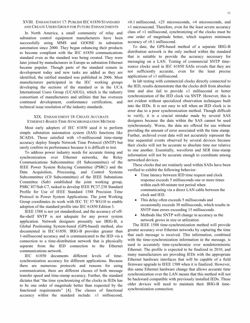
XVIII. ENHANCEMENT 17: PUBLISH IEC 61850 STANDARD AND CREATE USERS GROUP FOR FUTURE ENHANCEMENTS In North America, a small community of relay and
substation control equipment manufacturers have been successfully using MMS and GOOSE in substation automation since 2000. They began enhancing their products to become compliant with the IEC 61850 communications standard even as the standard was being created. They were later joined by manufacturers in Europe as substation Ethernet became popular. Though parts of the standard remain in development today and new tasks are added as they are identified, the ratified standard was published in 2006. Most manufacturers participated in the IEC working groups developing the sections of the standard or in the UCA International Users Group (UCAIUG), which is the industry consortium of manufacturers and utilities that has overseen continued development, conformance certification, and technical issue resolution of the industry standards.
XIX. ENHANCEMENT 18: CREATE ACCURATE ETHERNET-BASED TIME-SYNCHRONIZATION METHOD
Most early adopters of IEC 61850 used it to perform simple substation automation system (SAS) functions like SCADA. Those satisfied with ±5-millisecond time-stamp accuracy deploy Simple Network Time Protocol (SNTP) but rarely confirm its performance because it is difficult to test.
To address power industry needs for accurate timing and synchronization over Ethernet networks, the Relay Communications Subcommittee (H Subcommittee) of the IEEE Power System Relaying Committee (PSRC) and the Data Acquisition, Processing, and Control Systems Subcommittee (C0 Subcommittee) of the IEEE Substations Committee (Sub) established the joint working group, PSRC H7/Sub C7, tasked to develop IEEE PC37.238 Standard Profile for Use of IEEE Standard 1588 Precision Time Protocol in Power System Applications. The joint Working Group coordinates its work with IEC TC 57 WG10 to enable adoption of the standard profile into IEC 61850 Edition 3.
IEEE 1588 is not yet standardized, and the accuracy of off-the-shelf SNTP is not adequate for any power system application. Network designers presently use IRIG-B, a Global Positioning System-based (GPS-based) method, also documented in IEC 61850. IRIG-B provides greater than 1-millisecond accuracy and is communicated to the IED via a connection to a time-distribution network that is physically separate from the IED connection to the Ethernet communications network.
IEC 61850 documents different levels of time-synchronization accuracy for different applications. Because there are numerous protocols and reasons for using communication, there are different classes of both message transfer speed and time-stamp accuracy. Further, the standard dictates that “the time synchronizing of the clocks in IEDs has to be one order of magnitude better than requested by the functional requirements” [4]. The classes of functional accuracy within the standard include: ±1 millisecond,
±0.1 millisecond, ±25 microseconds, ±4 microseconds, and ±1 microsecond. Therefore, even for the least severe accuracy class of ±1 millisecond, synchronizing of the clocks must be one order of magnitude better, which requires minimum accuracy of ±0.1 millisecond.
To date, the GPS-based method of a separate IRIG-B distribution network is the only method within the standard that is suitable to provide the accuracy necessary for messaging on a LAN. Testing of commercial SNTP time-source clocks used in IEC 61850 SASs reveals that they are not sufficiently accurate, even for the least precise applications of ±1 millisecond.
In lab testing with commercial clocks directly connected to the IED, results demonstrate that the clocks drift from absolute time and also fail to provide ±1 millisecond or better synchronization of the IED clock via SNTP. However, this is not evident without specialized observation techniques built into the IEDs. It is not easy to tell when an IED clock is in error due to a poor synchronization method. Though difficult to verify, it is a crucial mistake made by several SAS designers because the data within the SAS cannot be used synchronously. Worse, the data are offered for use without providing the amount of error associated with the time stamp. Further, archived event data will not accurately represent the true sequential events observed by several devices because their clocks will not be accurate to absolute time nor relative to one another. Essentially, waveform and SER time-stamp information will not be accurate enough to coordinate among networked devices.
These clocks that are routinely used within SASs have been verified to exhibit the following behavior:
• Time latency between IED time request and clock response exceeds 5 milliseconds one or more times within each 60-minute test period when communicating via a direct LAN cable between the clock and IED.
• This delay often exceeds 5 milliseconds and occasionally exceeds 30 milliseconds, which results in SNTP time errors exceeding 15 milliseconds.
• Methods like SNTP will change in accuracy as the network grows in size or utilization.
The IEEE 1588 time-synchronization method will provide greater accuracy over Ethernet networks by capturing the time that each message is received. This information, combined with the time-synchronization information in the message, is used to accurately time-synchronize over nondeterministic Ethernet. The profile is expected to be finalized in 2010, and many manufacturers are providing IEDs with the appropriate Ethernet hardware interfaces that will be capable of a field firmware upgrade to IEEE 1588 when it is finalized. However, this same Ethernet hardware change that allows accurate time synchronization over the LAN means that this method will not be backward compatible with previously installed IEDs. These older devices will need to maintain their IRIG-B time-synchronization connection.

12
XX. ENHANCEMENT 19: IEC 61850 ADOPTION OF FIXED-RATE MEASUREMENT AND PUBLICATION FOR SV In order to ensure unrestricted future development and
interoperable use of SV applications, the original protocol description, IEC 61850-9-2 process bus protocol, was open to different technical interpretations, which would most likely not be interoperable. As customers began showing interest in demonstration projects, the UCAIUG created and published standardized implementation guidelines for substation applications, IEC 61850-9-2 Lite Edition, to ensure interoperability. Specifically, fixed-rate sampling and fixed-rate SV message publication were standardized, as well as the concept of a merging unit. Although future installations may use intelligent instrument transformers that directly publish SV, a merging unit connects to conventional instrument transformers, digitizes and time-stamps the samples, and publishes them via SV messages. For protection-class applications, the sampling source performs 80 samples per cycle and publishes 80 messages per cycle. Each SV message, or Ethernet packet, contains a single instance of voltage and current samples and is published immediately after being sampled. For power quality class applications, including power quality metering and waveform recording, this sampling rate may not be sufficient. Therefore, a second sample rate of 256 samples per cycle was chosen. The samples are collected and published as eight time-stamped groups of samples per Ethernet packet at 32 times per cycle. These SV messages are published at an unchanging fixed rate, which is faster, but similar to GOOSE heartbeat mode publication. The information exchange for SV is the same multicast publisher/subscriber mechanism as GOOSE. The time stamp is added to the values so the subscriber can check the timeliness of the values and align the samples from multiple sources for further processing.
XXI. ENHANCEMENT 20: DEVELOPMENT OF IEC 61850-90-1 AND IEC 61850-90-2 FOR COMMUNICATION
OUTSIDE SUBSTATIONS SRO protocols, like MIRRORED BITS communications, have
been used successfully for over a decade for intrasubstation applications, similar to GOOSE over a LAN, but, more importantly, for intersubstation applications. In 2009, IEC TC 57 published the Draft Technical Report for communication between substations (IEC 61850-90-1) to enable GOOSE to be used for applications previously performed with MIRRORED BITS communications and IEEE C37.118 synchrophasor messaging, including the following:
• Distance line protection with permissive teleprotection scheme.
• Distance line protection with blocking teleprotection scheme.
• Directional comparison protection. • Transfer/direct tripping. • Interlocking. • Multiphase automatic reclosing application for parallel
line systems.
• Current differential line protection. • Phase comparison protection. • Fault locator system (multiterminals). • System integrity protection schemes (SIPS). • Real-time predictive generator shedding. • Out-of-step detection. • Synchrophasor applications. • Remedial action schemes (RASs). • Islanding detection and management.
A similar activity is underway to standardize the use of IEC 61850 for communication between substations and control centers. It will be published as IEC 61850-90-2.
XXII. ENHANCEMENT 21: IEC 61850 ADOPTION OF FIXED-LENGTH ENCODING OF GOOSE CONTENTS
When the flexible data pool of IEC GOOSE replaced the DNA block and bit pair specification of UCA GOOSE, it also extended the message size from the original 259 bytes up to a maximum permitted Ethernet frame size of 1,518 bytes. Some data types, and therefore the message itself, were defined to vary in length to reduce the number of bytes if a data element was known to never reach its maximum size. Recent changes to IEC 61850-8.1 support the ability to force these values to always be transferred as their maximum number of bytes to simplify the decoding and processing by the subscribers. The minimal increase in message size is negligible to the transport process.
XXIII. ENHANCEMENT 22: RESTORATION OF MESSAGE PERFORMANCE AND TIME-ACCURACY MEASURES
In early June 2003, the authors of IEC TC 57 made enhancements to the Part 10 Conformance Testing draft. The scope of these enhancements included a test to verify the ability of the IED to communicate time-stamped information about an instrumented event. It was suggested that an accurate time stamp relies on several separate functions, including the clock accurately decoding the received signal, accurate synchronization of the IED clock to the received signal, timely IED detection of change of state, and accurate use of IED clock values to time-stamp the data. A second test verified incoming GOOSE and IEC 61850 commanded control (GCNTL) messages by measuring the time latency between the receipt of the incoming message and a logical change of state in the device and/or a physical contact output change of state. For outgoing GOOSE and GCNTL messages, the test measured the time latency between the logical change of state in the device and/or a physical contact input change of state and the transmission of the associated GOOSE or GCNTL message.
Unfortunately, the editing process removed these tests based on the perception that performance tests, unless against limits explicitly stated in other parts of IEC 61850, are essential for system functionality but of no relevance for a conformity test. The verification for correctness of vendor statements regarding performance was also said to be of no relevance for a conformity test. This has proven to cause confusion and concern among the users of IEC 61850, and the

13
UCAIUG has begun the process to restore these tests. A draft of “Test Procedures for GOOSE Performance According to IEC 61850-5 and IEC 61850-10 Version 0.2b” is presently in development. Also, concurrent evaluation of modernizing testing for digital communications performance is underway within C9 IEEE 1686 and H TF1 IEEE C37.115.
XXIV. CONCLUSION Many efforts and enhancements have been made in the last
decade to mitigate the nondeterministic and nonredundant nature of Ethernet networks. However, due to its intended cloudlike behavior, which is preferable in nonmission-critical applications, it may still be unacceptable as a transport mechanism. Ethernet as a connection mechanism for IED data flow seems to be a good choice. IED manufacturers have demonstrated an ability to develop robust Ethernet interfaces for use in wide temperature ranges. However, even the most recent compensation enhancements to Ethernet and IEC 61850 messaging rely on failure recovery, rather than true redundancy. Shared bandwidth techniques simply cannot provide the certainty needed for synchronous multicast messaging. Design for reliability methods suggest that Ethernet as a connection mechanism should be combined with a deterministic, nonshared bandwidth-provisioning method for message transport to satisfy the power system needs for the following:
• Resiliency • Reliability • Redundancy instead of recovery • Deterministic behavior • Traffic prioritization • Bandwidth reservation
XXV. REFERENCES [1] D. Hou and D. Dolezilek, “IEC 61850 – What It Can and Cannot Offer
to Traditional Protection Schemes,” proceedings of the 35th Annual Western Protective Relay Conference, Spokane, WA, October 2008.
[2] V. M. Flores, D. Espinosa, J. Alzate, and D. Dolezilek, “Case Study: Design and Implementation of IEC 61850 From Multiple Vendors at CFE La Venta II,” proceedings of the 9th Annual Western Power Delivery Automation Conference, Spokane, WA, April 2007.
[3] K. Schwarz, “IEEE UCA™ and IEC 61850 Applied in Digital Substations,” proceedings of DistribuTECH Europe, Vienna, Austria, October 2000.
[4] E. Udren, S. Kunsman, and D. Dolezilek, “Significant Substation Communication Standardization Developments,” proceedings of the 2nd Annual Western Power Delivery Automation Conference, Spokane, WA, April 2000.
[5] IEEE PSRC H6Special Report, Application Considerations of IEC 61850/UCA 2 for Substation Ethernet Local Area Network Communication for Protection and Control, 2005.
[6] ISO/IEC DTR 8802-1:1999, Information Technology – Telecommunications and Information Exchange Between Systems – Local and Metropolitan Area Networks – Technical Reports and Guidelines – Part 1: Overview of Local Area Network Standards.
[7] IEC 61850 Standard. Available: http://www.iec.ch. [8] IEC 60870 Standard. Available: http://www.iec.ch. [9] E. Udren, “IEEE (ANSI) Device Number 16 – Ethernet Switches and
Routers.”
XXVI. BIOGRAPHY David Dolezilek is the technology director of Schweitzer Engineering Laboratories, Inc. He is an electrical engineer (BSEE Montana State University) with experience in electric power protection, integration, automation, communication, control, SCADA, and EMS. He has authored numerous technical papers and continues to research innovative technology affecting the industry. Dolezilek is a patented inventor and participates in numerous working groups and technical committees. He is a member of IEEE, the IEEE Reliability Society, CIGRE working groups, and two IEC technical committees tasked with global standardization and security of communications networks and systems in substations.
© 2010 by Schweitzer Engineering Laboratories, Inc. All rights reserved.
20101202 • TP6435-01