Using High Power Density Single Phase PWM Rectifier with ... · Using High Power Density Single...
10
Middle-East Journal of Scientific Research 12 (12): 1899-1908, 2012 ISSN 1990-9233 © IDOSI Publications, 2012 DOI: 10.5829/idosi.mejsr.2012.12.12.1252 Corresponding Authro: S. Satheesh, Department of Electrical and Electronics Engineering, Bharath University, Bharath University, Chennai-600073, Tamilnadu, India. 1899 Using High Power Density Single Phase PWM Rectifier with Active Ripple Energy Storage in Single Phase to Three Phase Drive System S. Satheesh and S. Ramamoorthy Department of Electrical and Electronics Engineering, Bharath University, Bharath University, Chennai-600073, Tamilnadu, India Abstract: The main objective of this project is single-phase to three-phase drive system composed of High power density PWM rectifiers with active ripple energy storage. The proposed topology permits to reduce the rectifier switch currents, the harmonic distortion at the input converter side and presents improvements on the fault tolerance characteristics. With the decrease in the number of switches, the total energy loss of the proposed system may be lower than that of a conventional one. It is well known that there exist second-order harmonic current and corresponding ripple voltage on dc bus for single phase PWM rectifiers. The low frequency harmonic current is normally filtered using a bulk capacitor in the bus which results in low power density. This proposed an active ripple energy storage method that can effectively reduce the energy storage capacitance. The feed-forward control method and design considerations are provided. The circuit employs conventional PWM switching strategy to control its output voltage. With a suitable control strategy, including the pulse width modulation technique (PWM) is developed and simulation results are presented as well in order to known about the important characteristics features of the proposed system. Key words: High power density converter Single phase rectifier Three phase inverterInduction motor Ac-dc-Ac power converter INTRODUCTION density of a single-phase converter, it is essential to Several solutions have been proposed when the low-frequency ripple energy [4]. objectiveis to supply a three-phase motor from a In addition, the previous work verified the feasibility single-phase ac main [1]. It is quite common to have only of increasing the system power density by using active a single phase power grid in residential, commercial, ripple energy storage method. In this paper, a high power manufacturing and mainly in rural areas, while the density single phase PWM rectifier is proposed and a adjustable speed drives may Request a three-phase power feed-forward control method is provided. This feed- grid. Fault-tolerant multi-phase converter systems have forward method can help the auxiliary active energy been extensively researched for aircraft application storage circuit working as a parallel active power filter for because of their inherent fault tolerance capability [2]. filtering out the low frequency ripples current from the Accordingly, high power density single phase H-bridge rectifier proposed single phase PWM rectifier. converter modules are desirable for such systems. One of The proposed topology of the ripple energy storage the important characteristics of the single-phase system Method is depicted in a bidirectional buck-boost is the low-frequency ripple on the dc link when the ac converter is connected as auxiliary circuit at the output of input voltage and current are sinusoidal [3]. To limit this a typical single-phase bidirectional PWM rectifier. low-frequency ripple, a bulk electrolytic dc-link capacitor Since second-order harmonic current is generated is usually required, which results in large converter from the single phase H-bridge rectifier, the auxiliary volume, low power density and poor life-time due to the circuit is used as a parallel current filter. The proposed electrolytic capacitors needed. To improve the power system is conceived to operate where the single-phase reduce the dc-link capacitor required for filtering the
Transcript of Using High Power Density Single Phase PWM Rectifier with ... · Using High Power Density Single...

Middle-East Journal of Scientific Research 12 (12): 1899-1908, 2012ISSN 1990-9233© IDOSI Publications, 2012DOI: 10.5829/idosi.mejsr.2012.12.12.1252
Corresponding Authro: S. Satheesh, Department of Electrical and Electronics Engineering, Bharath University,Bharath University, Chennai-600073, Tamilnadu, India.
1899
Using High Power Density Single Phase PWM Rectifier withActive Ripple Energy Storage in Single Phase to Three Phase Drive System
S. Satheesh and S. Ramamoorthy
Department of Electrical and Electronics Engineering, Bharath University,Bharath University, Chennai-600073, Tamilnadu, India
Abstract: The main objective of this project is single-phase to three-phase drive system composed of Highpower density PWM rectifiers with active ripple energy storage. The proposed topology permits to reduce therectifier switch currents, the harmonic distortion at the input converter side and presents improvements on thefault tolerance characteristics. With the decrease in the number of switches, the total energy loss of theproposed system may be lower than that of a conventional one. It is well known that there exist second-orderharmonic current and corresponding ripple voltage on dc bus for single phase PWM rectifiers. The lowfrequency harmonic current is normally filtered using a bulk capacitor in the bus which results in low powerdensity. This proposed an active ripple energy storage method that can effectively reduce the energy storagecapacitance. The feed-forward control method and design considerations are provided. The circuit employsconventional PWM switching strategy to control its output voltage. With a suitable control strategy, includingthe pulse width modulation technique (PWM) is developed and simulation results are presented as well in orderto known about the important characteristics features of the proposed system.
Key words: High power density converter Single phase rectifier Three phase inverterInduction motor Ac-dc-Ac power converter
INTRODUCTION density of a single-phase converter, it is essential to
Several solutions have been proposed when the low-frequency ripple energy [4].objectiveis to supply a three-phase motor from a In addition, the previous work verified the feasibilitysingle-phase ac main [1]. It is quite common to have only of increasing the system power density by using activea single phase power grid in residential, commercial, ripple energy storage method. In this paper, a high powermanufacturing and mainly in rural areas, while the density single phase PWM rectifier is proposed and aadjustable speed drives may Request a three-phase power feed-forward control method is provided. This feed-grid. Fault-tolerant multi-phase converter systems have forward method can help the auxiliary active energybeen extensively researched for aircraft application storage circuit working as a parallel active power filter forbecause of their inherent fault tolerance capability [2]. filtering out the low frequency ripples current from the
Accordingly, high power density single phase H-bridge rectifier proposed single phase PWM rectifier.converter modules are desirable for such systems. One of The proposed topology of the ripple energy storagethe important characteristics of the single-phase system Method is depicted in a bidirectional buck-boostis the low-frequency ripple on the dc link when the ac converter is connected as auxiliary circuit at the output ofinput voltage and current are sinusoidal [3]. To limit this a typical single-phase bidirectional PWM rectifier.low-frequency ripple, a bulk electrolytic dc-link capacitor Since second-order harmonic current is generatedis usually required, which results in large converter from the single phase H-bridge rectifier, the auxiliaryvolume, low power density and poor life-time due to the circuit is used as a parallel current filter. The proposedelectrolytic capacitors needed. To improve the power system is conceived to operate where the single-phase
reduce the dc-link capacitor required for filtering the

Middle-East J. Sci. Res., 12 (12): 1899-1908, 2012
1900
Fig. 1: Functional Block Diagaram
utility grid is the unique option available. Compared to the The grid-side voltage was sinusoidal,conventional topology, the proposed system permits: toreduce the rectifier switch currents; the total harmonic u = U sin ( t)distortion (THD) of the grid current with same switchingfrequency or the switching frequency with same THD of U is the peak voltage of the grid-side voltage and is itsthe grid current; and to increase the fault tolerance angular frequency.characteristics. In addition, the losses of the proposedsystem may be lower than that of the conventional In unity power factor conditions the switches arecounterpart. ideal devices and the load is purely resistive load,
Single Phase Pwm Rectifier: It is an Ac to Dc power i = I sin ( t)converter, which is implemented using forced commutatedpower electronic semiconductor switches. Today, where i is the current peak insulated gate bipolar transistors are typical switching From the above analysis as well as the circuit showndevices. Different from diode bridge rectifiers, PWM in Figure 2, the mathematical model of rectifier can berectifiers achieve bidirectional power flow. The application obtainedof PWM rectifier topology includes:
In frequency converters this property makes itpossible to perform regenerative braking. The State Vector Relationship of Rectifier: The loss ofPWM rectifiers are also used in distributed power the converter can be supposed to ignore, so input andgeneration applications, such as micro turbines, fuel output power balance, the circuit equation of single-phasecells and windmills. PWM rectifier model is shown as follow.Adjustable speed drives including harmonic filteringfunction I U = I U
The Mathematical Model: The circuit of single-phase In the above equation, Us, Is, are the grid-sidebridge rectifier is shown in Figure 2 because the output voltage and grid-side current, U , I are the voltage andvoltage contains the harmonic, whose frequency is 100Hz; current of DC side.add resonant circuit as its filter. In order to establish the Thus the following conclusions can be drawn: wemathematical model of the main circuit, we firstly make the can control the DC side through the control of the ACfollowing assumptions: side; and control the AC side through the control of the
s s s
s s
s s s
s
S s dc dc
dC dc
Middle-East J. Sci. Res., 12 (12): 1899-1908, 2012
1901
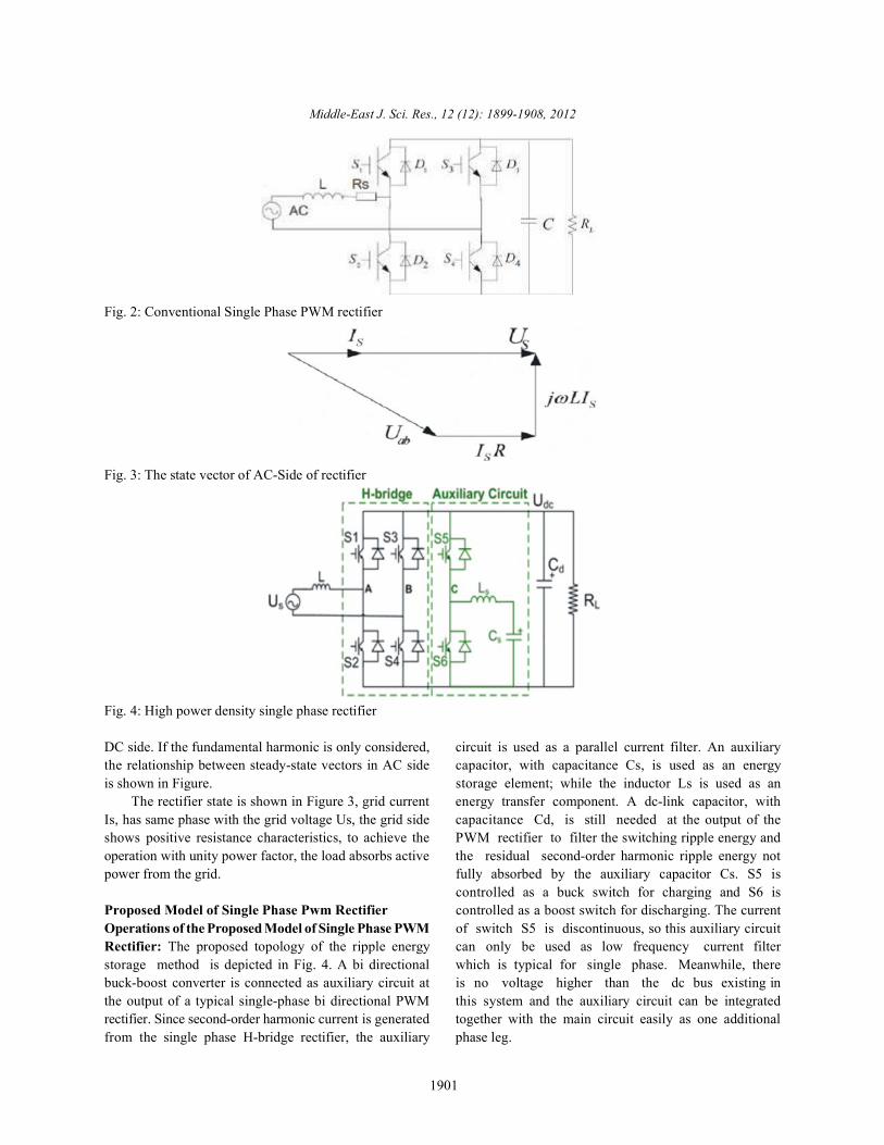
Fig. 2: Conventional Single Phase PWM rectifier
Fig. 3: The state vector of AC-Side of rectifier
Fig. 4: High power density single phase rectifier
DC side. If the fundamental harmonic is only considered, circuit is used as a parallel current filter. An auxiliarythe relationship between steady-state vectors in AC side capacitor, with capacitance Cs, is used as an energyis shown in Figure. storage element; while the inductor Ls is used as an
The rectifier state is shown in Figure 3, grid current energy transfer component. A dc-link capacitor, withIs, has same phase with the grid voltage Us, the grid side capacitance Cd, is still needed at the output of theshows positive resistance characteristics, to achieve the PWM rectifier to filter the switching ripple energy andoperation with unity power factor, the load absorbs active the residual second-order harmonic ripple energy notpower from the grid. fully absorbed by the auxiliary capacitor Cs. S5 is
Proposed Model of Single Phase Pwm Rectifier controlled as a boost switch for discharging. The currentOperations of the Proposed Model of Single Phase PWM of switch S5 is discontinuous, so this auxiliary circuitRectifier: The proposed topology of the ripple energy can only be used as low frequency current filterstorage method is depicted in Fig. 4. A bi directional which is typical for single phase. Meanwhile, therebuck-boost converter is connected as auxiliary circuit at is no voltage higher than the dc bus existing inthe output of a typical single-phase bi directional PWM this system and the auxiliary circuit can be integratedrectifier. Since second-order harmonic current is generated together with the main circuit easily as one additionalfrom the single phase H-bridge rectifier, the auxiliary phase leg.
controlled as a buck switch for charging and S6 is

Middle-East J. Sci. Res., 12 (12): 1899-1908, 2012
1902
Control Analysis: As mentioned above, there exists A more straightforward, the compensation currentsecond-order ripple power in the single phase system.The ripple power after the H-bridge can be expressed as:
pr = pr- peak sin(2 t)
where is the supply frequency.Assume all the ripple energy is stored in the auxiliary
capacitor:
With this, the low frequency ripple current and ripplevoltage in the capacitor are shown in equation:
where constant ‘Const’ is given by:
The energy storage capacitor Cs is selected as 140µFto meet the minimum requirement and the energy transferinductor Ls is designed as 40 µH according to in thedesign consideration section. Due to that, the switchingfrequency 20 kHz is much higher than the Ls and Csresonant frequency. At each switching period, the dc-linkvoltage and auxiliary capacitor voltage can be consideredas quasi-static. This means the inductor charging slopeand discharging slope can eachbe considered as a fixedvalue within each switching period.
Then, the duty cycle for the charging anddischarging phases can be derived and the second-orderripple energy can be accurately filtered out from theH-bridge.
Fig. 5: Auxiliary circuit working as parallel active rippleCurrent filters
is used to regulate the low frequency ripple current(shown in (Fig. 5). Using the previous method, theaverage compensation current within one switchingperiod should be equal to the low frequency ripplecurrent, then the duty cycle for the charging anddischarging phases are derived as.
The control schematic of the system is shown inFig. 5. The rectifier duty cycle and the measured ac-sidecurrent are used to generate the ripple current referencefor the auxiliary circuit. The dc link voltage and auxiliarycapacitor voltage are sensed to generate the duty cyclefor both charging and discharging phases. Within theduty cycle generation block, if the compensation currentis positive, the auxiliary circuit is controlled in buck modeto assimilate the ripple power from the dc link charging theauxiliary energy storage capacitor. Similarly, when thecompensation current is negative, the auxiliary circuit iscontrolled in boost mode to release the ripple energystored back into the dc link.
The auxiliary capacitor mean voltage control loop isrequired to prevent the Cs from over charging or undercharging. The PLL block is designed as shown in Fig. 6.
Design Considerations: For single phase H-bridgerectifier, the modulation method is specified to achieveboth the minimum loss and balanced temperaturedistribution.
For the auxiliary circuit, the auxiliary capacitor isselected according to the ripple energy requirements andthe auxiliary inductor is designed as below.
Modulation Method: The single phase discontinuousPWM modulation. One phase leg will not switch withinhalf of the supply frequency. It can lead to the minimumswitching loss.
Auxiliary Inductance Selection: There are two criteria forselecting the auxiliary inductance:
Peak current boundary The Discontinuous Current Mode (DCM) boundary,
The maximum current in the auxiliary circuit must besmaller than the peak current requirement of the selectedpower semiconductor:
Buck_Slope × D1 × T I Boost_Slope × D1 × T Is peak s peak
Then, the auxiliary inductance selection based on thepeak current requirement is calculated as:

Middle-East J. Sci. Res., 12 (12): 1899-1908, 2012
1903
Fig. 6: Control schematic figure for the system
Fig. 7: Single phase discontinuous PWM modulation metho
Fig. 8: The auxiliary inductance selection range

Middle-East J. Sci. Res., 12 (12): 1899-1908, 2012
1904
Fig. 9: Simulation of with and without auxiliary circuit of high power density single phase PWM rectifier
Fig. 10: Proposed model of single phase to three phase drive system using high power density single phase PWMrectifier with active ripple energy storage

Middle-East J. Sci. Res., 12 (12): 1899-1908, 2012
1905
Fig. 11: Simulation of proposed model of single phase to three phase drive system using high power density singlephase PWM rectifier with active ripple energy storage
Fig. 12: Closed loop system of high power density single phase PWM rectifier

Middle-East J. Sci. Res., 12 (12): 1899-1908, 2012
1906
Fig. 13: Three phase inverter connected with load
Fig. 14: Simulation result of source voltage and source current normal rectifier and high power density single phasePWM rectifier

Middle-East J. Sci. Res., 12 (12): 1899-1908, 2012
1907
Fig. 15: Output voltage of normal rectifier and high power density single phase PWM rectifier
Fig. 16: Simulation result of three phase inverter
Then, the auxiliary inductance selection based on the DCM requirement is calculated as:

Middle-East J. Sci. Res., 12 (12): 1899-1908, 2012
1908
REFERNECES
Simulation Results: The proposed rectifier system is Three-Phase Drive System Using Two Parallelconstructed using Matlab/Simulink tools and simulated in Single-Phase Rectifiers Senior Member, IEEE, Euzeliorder to achieve the performance characteristics under Cipriano dos Santos Jr., Member, IEEE, Nady Rochadifferent parameters changes. Using Matlab/Simulink to and Edgard Luiz Lopes Fabr´ cio 25(5).simulate, the parameters of simulation are shown as 2. Ricardo Quadros Machado, Simone Buso, 2006. Afollows. Line-Interactive Single-Phase to Three-Phase
The switching frequency of device is 20 kHz, Pomilio, Senior Member, IEEE, 21(6).The grid-side AC voltage is E = 145V, 50Hz 3. Dong-Choon Lee, 2007. Control of Single-Phase-to-Input line inductance: 5mH Three-Phase AC/DC/AC PWM Converters forThe capacitor in DC side is C = 200uF, Induction Motor Drives Member, IEEE and Young-Capacitance in auxiliary storage: 1000uf Sin Kim, 54(2).Inductance in auxiliary circuit: 10uH 4. Enjeti, P. and A. Rahman, 0000. A New Single PhaseLoad: 50 ohm Resistive to Three Phase Converter with Active Input Current
CONCLUSION Electronics Laboratory Department Of Electrical
In this work, an active ripple energy storage methodis proposed to increase the single phase PWM rectifier’spower density. Based on analysis, simulation andexperiment, the following conclusions can be drawn:
Firstly, the proposed auxiliary circuits will bring novoltage higher than the dc bus in the system and itcan be easily integrated together with the H-bridgerectifier as an additional phase leg. Different from thetraditional parallel active power filter, the auxiliarycircuit compensation current is in discontinuouscurrent mode so that it can only filter out the lowfrequency ripple current that dominates in singlephase rectifier system. Secondly, the proposed feed-forward control methodcan generate the compensation current reference asfast as one switching period and can effectively filterout the low frequency ripple current from the H-bridge rectifier. Thirdly, although the total capacitance will decreasedramatically compared with traditional method, thetotal ripple current in capacitors will increase byusing the active method. Finally, simulation resultswere provided for verification purposes.
1. Cursino Brenda Jacobina, 2010. Single-Phase to
Converter System, Member, IEEE and José Antenor
Shaping for Low Cost Ac Motor Drives Power
Engineering Texas A&M University College Station.