Using georeferenced images in Civil3D - Tips for Bundy · PDF filemethods restricts user to...
10
using georeferenced images in Civil3D 1/27/09 pg 1 of 1 Using georeferenced images in Civil3D LB 1/27/09 Background: NRCS provides geodata in UTM, Nad83, distance meters. Civil 3D should be able to import and project this data for engineers. The industry standard in California, is CA State Plane Coordinate system (CA SPC). While shapefiles are handled well using the Map | Import tool, MrSid image files must be inserted another way. The goal is to create a useful template for drawings that contains georeferenced aerial and topo base maps in CA SPC. Methods tried: Numerous methods were evaluated with no success. These methods and observations are outlined below: 1. Map | Image Insert a. This method allows the insertion point and scaling to be changed. This methods restricts user to keeping projection UTM, but distance units can be changed to feet. Drawing is then UTM, ft. 2. Data Connect a. This is a great tool if it worked. Two problems i. the sid files are large (2.5 GB for Siskiyou County, 1 of 2 tiles) and Autodesk help advised that “Our general recommendation is to stay under 500 million pixels per image, and I suspect that even your 1 gb image is much larger than that” ii. I consistently receive the error message “there was an error adding data to Map”. Autodesk help advised “The 2009 release of Map 3D did not support raster reprojection, though it generally works”. In my case, it does not work. 3. Reproject MrSid source files to desired projection. a. These files are provided by the National Geospatial Center. I was told by GIS specialists at the state office that this data is only available in the format provided. No reprojection or tiling to reduce file size is possible. 4. Use ArcMap to clip image, save as tif, and insert tif image into CAD a. We created a set of tiles for our county and tried this method. It is not efficient since the tiles must be selected for each drawing. b. The quality of the tif images do not compare to the MrSid files and do not print well. We found the images useless. Solution: Create a library of drawings using Map query tools and attached drawings. These drawings can then be xref’ed to the design drawing to save file size.
Transcript of Using georeferenced images in Civil3D - Tips for Bundy · PDF filemethods restricts user to...
using georeferenced images in Civil3D 1/27/09 pg 1 of 1
Using georeferenced images in Civil3D LB 1/27/09 Background: NRCS provides geodata in UTM, Nad83, distance meters. Civil 3D should be able to import and project this data for engineers. The industry standard in California, is CA State Plane Coordinate system (CA SPC). While shapefiles are handled well using the Map | Import tool, MrSid image files must be inserted another way. The goal is to create a useful template for drawings that contains georeferenced aerial and topo base maps in CA SPC. Methods tried: Numerous methods were evaluated with no success. These methods and observations are outlined below:
1. Map | Image Insert a. This method allows the insertion point and scaling to be changed. This
methods restricts user to keeping projection UTM, but distance units can be changed to feet. Drawing is then UTM, ft.
2. Data Connect a. This is a great tool if it worked. Two problems
i. the sid files are large (2.5 GB for Siskiyou County, 1 of 2 tiles) and Autodesk help advised that “Our general recommendation is to stay under 500 million pixels per image, and I suspect that even your 1 gb image is much larger than that”
ii. I consistently receive the error message “there was an error adding data to Map”. Autodesk help advised “The 2009 release of Map
3D did not support raster reprojection, though it generally works”. In my case, it does not work.
3. Reproject MrSid source files to desired projection. a. These files are provided by the National Geospatial Center. I was told by
GIS specialists at the state office that this data is only available in the format provided. No reprojection or tiling to reduce file size is possible.
4. Use ArcMap to clip image, save as tif, and insert tif image into CAD a. We created a set of tiles for our county and tried this method. It is not
efficient since the tiles must be selected for each drawing. b. The quality of the tif images do not compare to the MrSid files and do not
print well. We found the images useless. Solution: Create a library of drawings using Map query tools and attached drawings. These drawings can then be xref’ed to the design drawing to save file size.
using georeferenced images in Civil3D 1/27/09 pg 2 of 2
Procedure:
1. Create dummy drawing that holds mrsid image in original coordinate system, UTM Nad83, zone10, meters.
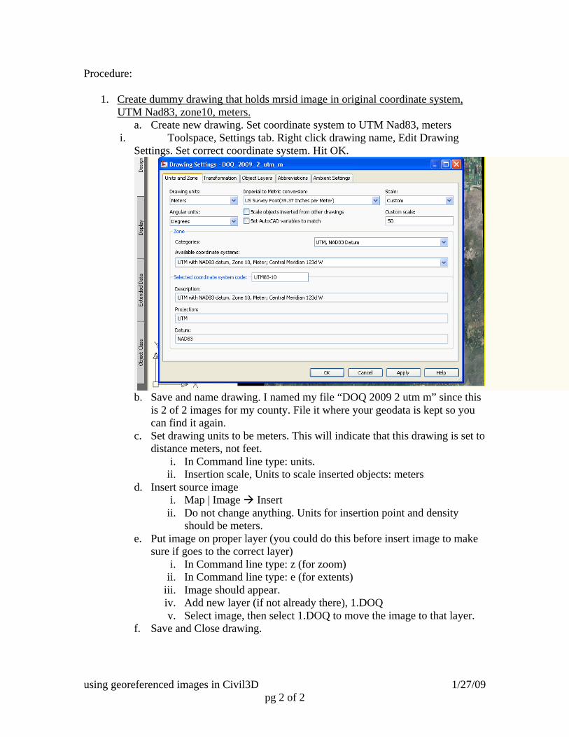
a. Create new drawing. Set coordinate system to UTM Nad83, meters i. Toolspace, Settings tab. Right click drawing name, Edit Drawing
Settings. Set correct coordinate system. Hit OK.
b. Save and name drawing. I named my file “DOQ 2009 2 utm m” since this is 2 of 2 images for my county. File it where your geodata is kept so you can find it again.
c. Set drawing units to be meters. This will indicate that this drawing is set to distance meters, not feet.
i. In Command line type: units. ii. Insertion scale, Units to scale inserted objects: meters
d. Insert source image i. Map | Image Insert
ii. Do not change anything. Units for insertion point and density should be meters.
e. Put image on proper layer (you could do this before insert image to make sure if goes to the correct layer)
i. In Command line type: z (for zoom) ii. In Command line type: e (for extents)
iii. Image should appear. iv. Add new layer (if not already there), 1.DOQ v. Select image, then select 1.DOQ to move the image to that layer.
f. Save and Close drawing.

using georeferenced images in Civil3D 1/27/09 pg 3 of 3
2. Create drawing that contains image in different projection, CA SPC Nad 83, ft. You will attach and query the UTM drawing to get it to reproject for you.
a. Create new drawing. Set coordinate system to CA SPC, Nad83, feet. i. Toolspace, Settings tab. Right click drawing name, Edit Drawing Settings. Set
correct coordinate system. Hit OK.
b. Save and name drawing. Good label is “DOQ 2009 2 caspc83 sft”. File it
where your geodata is kept so you can find it again. c. Set drawing units to be feet. This will indicate that this drawing is set to
distance feet, not meters. i. In Command line type: units
ii. Insertion scale, Units to scale inserted objects: feet d. Insert image. This is where things get tricky
i. Select Map | Drawings | Define/Modify Drawing Set

using georeferenced images in Civil3D 1/27/09 pg 4 of 4
ii. Click Attach. Navigate to the drawing you created with the UTM,
m image. You may need to “create an alias” if you don’t have access to the folder. Look up how to do this in CAD help.
iii. Select file. Click Add. Hit OK.
iv. Hit OK again.

using georeferenced images in Civil3D 1/27/09 pg 5 of 5
e. Drawing is now attached but not visible. You have to tell CAD what to display by doing a “query”.
i. Map | Query | Define query
ii. Click on Location
using georeferenced images in Civil3D 1/27/09 pg 6 of 6
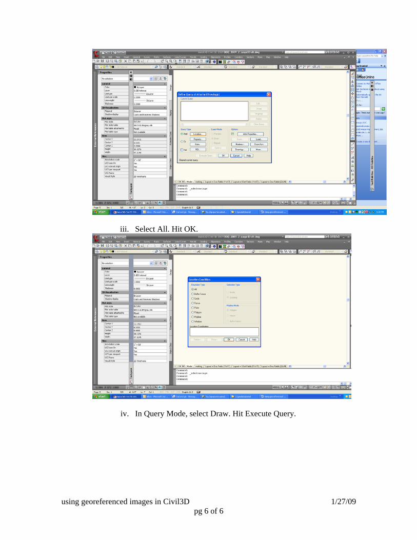
iii. Select All. Hit OK.
iv. In Query Mode, select Draw. Hit Execute Query.

using georeferenced images in Civil3D 1/27/09 pg 7 of 7
v. you may get an error message. Ignore this by hitting close.
vi. In command line type: z (zoom) vii. In command line type: e (extents)
viii. Make sure you put this image on the correct layer.
using georeferenced images in Civil3D 1/27/09 pg 8 of 8
YOU NOW HAVE A LIBRARY OF GEOREFERENCED IMAGES. YOU SHOULD NEVER HAVE TO DO THIS AGAIN UNLESS YOU NEED ANOTHER
PROJECTION
NOW TO USE THESE IMAGES……….
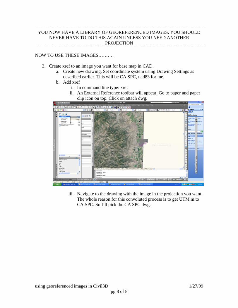
3. Create xref to an image you want for base map in CAD. a. Create new drawing. Set coordinate system using Drawing Settings as
described earlier. This will be CA SPC, nad83 for me. b. Add xref
i. In command line type: xref ii. An External Reference toolbar will appear. Go to paper and paper
clip icon on top. Click on attach dwg.
iii. Navigate to the drawing with the image in the projection you want. The whole reason for this convoluted process is to get UTM,m to CA SPC. So I’ll pick the CA SPC dwg.

using georeferenced images in Civil3D 1/27/09 pg 9 of 9
c. Image should insert properly. It may install over any linework in the drawing.
i. To move it back, select the image. (Shift+left click may not work since it is an xref)
ii. Right click on selected image, Display order, send to back. d. You may get a message that unreconciled new layers were found. This is a
warning in case multiple people work on one drawing. You can change the alert setting or reconcile.
i. To reconcile, go to layer manager or click link in warning message.
ii. Open sorted list of “unreconciled layers”. Select all layers. iii. Right click, reconcile. Message goes away.
Please report any errors and improvement to this process to [email protected]

using georeferenced images in Civil3D 1/27/09 pg 10 of 10