User’s Manual - Turner Designs€™s Manual May 18, 2018 P/N 998-2100 Revision 2.9 TURNER DESIGNS...
21
User’s Manual May 18, 2018 P/N 998-2100 Revision 2.9 TURNER DESIGNS 1995 N. 1 st Street San Jose, CA 95112 Phone: (408) 749-0994 FAX: (408) 749-0998
Transcript of User’s Manual - Turner Designs€™s Manual May 18, 2018 P/N 998-2100 Revision 2.9 TURNER DESIGNS...

User’s Manual
May 18, 2018 P/N 998-2100 Revision 2.9 TURNER DESIGNS 1995 N. 1st Street San Jose, CA 95112 Phone: (408) 749-0994 FAX: (408) 749-0998

Table of Contents
1. Introduction 1.1 Description 4
2. Inspection and Setup 2.1 Instrument Checklist 5 2.2 Housing Configurations 5 2.3 Optional Accessories 6 2.4 Functional Test for Cyclops with connector 7
3. Measurements with the Cyclops 3.1 Introduction 8 3.2 Setting the Gain 8 3.2.1 Gain Determination Procedure 8 3.2.2 Static Gain Control 9 3.2.3 Auto Gaining 9 3.3 Direct Concentration Calibration 9
3.3.1 Direct Concentration Calibration for Chlorophyll Cyclops 3.3.2 Direct Concentration Calibration for Turbidity Cyclops
10 10
4. Maintenance and Warranty 4.1 Maintenance 11 4.1.1 Rinsing 11 4.1.2 Care for the bulkhead connector 11 4.1.3 Cleaning the Optics 11 4.2 Warranty Terms 11 4.3 Warranty Service 12 4.4 Out of Warranty Service 12
Appendices A Specifications 14 B Recommended Measurement Practices 15 C Wiring Guide 16 D Pigtail Cable and Connector Information 17 E Controlling the Gain 18 F Linear Range, Quenching and Temperature Considerations 19 G Functional Test for Cyclops with no Connector 20 H Using the Cyclops Submersible Sensor with the DataBank 21

WASTE ELECTRICAL AND ELECTRONIC EQUIPMENT (WEEE) DIRECTIVE Turner Designs is in the business of designing and selling products that benefit the well-being of our environment. Accordingly, we are concerned with preserving the surroundings wherever our instruments are used and happy to work with customers by complying with the WEEE Directive to reduce the environmental impact resulting from the use of our products. WEEE Return Process: To arrange the return of an end-of-life product, proceed as follows:
If you purchased your instrument through a Turner Designs Distributor please contact your local representative. They will instruct you where to return the end-of-life product. If you purchased your instrument directly from Turner Designs please contact Turner Designs Customer Service By Phone: 1-408-212-4041 or Toll Free: (877) 316.8049 By Email: Customer Service at [email protected] Turner Designs will provide a WEEE RMA Number, a Shipping Account Number, and a Ship to Address. Package and ship the product back to Turner Designs.
The product will be dealt with per Turner Designs’ end-of-life recycling program in an environmentally friendly way.
Cyclops Submersible Sensor
998-2100 Rev. 2.9 Page 4
1. Introduction
1.1 Description
The Turner Designs Cyclops Submersible Sensor is an accurate single-channel detector that can be used for many different applications. It is designed for integration into multi-parameter systems from which it receives power and delivers a voltage output proportional to the concentration of the fluorophore, particle, or compound of interest.
The Cyclops voltage output can be correlated to concentration values by calibrating with a standard of known concentration. Effective April 1, 2017 all Cyclops-7 shipping will be Cyclops-7F. Updated to have a faster settling time, Cyclops-7F is ready to make measurements 1 second after power up.

Cyclops Submersible Sensor
998-2100 Rev. 2.9 Page 5
2. Inspection and Setup
2.1 Instrument Checklist
The Cyclops Submersible Sensor shipment package consists of:
Cyclops Submersible Sensor: Configured and factory scaled for the specified analysis (see Identification Letter stamped on the connector for specified analysis):
“C” = Chlorophyll
“R” = Rhodamine
“F” = Fluorescein
“P” = Phycocyanin
“E” = Phycoerythrin
“U” = CDOM / FDOM
“O” = Crude Oil
“B” = Optical Brighteners
“T” = Turbidity
“G” = Refined Fuels
“A” = PTSA
“L” = Tryptophan
“D” = Red Excitation
Test Criteria
2.2 Housing Configurations:
Stainless Steel Cyclops-7F (P/N: 2110-000-“Identification Letter”) Stainless Steel Cyclops-7 (P/N: 2100-000-“Identification Letter”)
Plastic or Titanium housings (recommended for highly corrosive environments or long term deployments). Titanium Cyclops-7F (P/N: 2110-000-“Identification Letter” T) Plastic Cyclops-7F (P/N: 2118-000-“Identification Letter”) Plastic Cyclops-7F with Titanium connector (P/N: 2118-000-“Identification Letter”T) Titanium Cyclops-7 (P/N: 2100-000-“Identification Letter” T) Plastic Cyclops-7 (P/N: 2108-000-“Identification Letter”) Plastic Cyclops-7 with Titanium connector (P/N: 2108-000-“Identification Letter”T)
6000 meter Cyclops-6K (P/N: 2160-000-“Identification Letter”)
No Connector Cyclops-7F (P/N: 2110-000-“Identification Letter”-NC). No Connector Cyclops-7 (P/N: 2100-000-“Identification Letter”-NC). Refer to Appendix G for wiring and functional testing.
2.3 Optional Accessories include:
Cyclops Pigtail Cables with Locking Sleeve (see Appendix D for more information)
“A” = PTSA“A” = PTSA

Cyclops Submersible Sensor
998-2100 Rev. 2.9 Page 6
0.6 meter Pigtail Cable with Locking Sleeve (P/N 2100-750)
5 meter Pigtail Cable with Locking Sleeve (P/N 2100-755) 10 meter Pigtail Cable with Locking Sleeve (P/N 2100-751)
25 meter Pigtail Cable with Locking Sleeve (P/N 2100-752)
50 meter Pigtail Cable with Locking Sleeve (P/N 2100-753) Note: Turner Designs recommends you do NOT tow sensors with cables.
DataBank Handheld Data Logger (see Appendix H) (P/N 2900-000)
Flow Cap (see Accessory Instructions on USB Flash Drive) Cyclops Stainless Steel and Titanium (P/N 2100-600) Cyclops Plastic (P/N 2100-608) Cyclops-6K (P/N 2160-600)
Shade Cap (see Accessory Instructions on USB Flash Drive)
Note: We recommend use of the shade cap as it provides a fixed distance for sample measurement and minimizes effects from ambient light. Cyclops Stainless Steel and Titanium (P/N 2100-701) Cyclops Plastic (P/N 2100-708) Cyclops-6K (P/N 2160-700)
Cyclops-7 Chlorophyll Standard Solution, Blue Excitation (p.n. 2100-320)
Note: Not for use with Cyclops-6K.
Solid Secondary Standard (SSS) for in vivo Chlorophyll, Phycocyanin, Phycoerythrin, Rhodamine, Fluorescein (see Accessory Instructions on USB Flash Drive) Cyclops Stainless Steel and Titanium (P/N 2100-900) Cyclops Plastic (P/N 2100-908) Cyclops-6K (P/N 2160-900)
Solid Secondary Standard (SSS) for UV Sensors (CDOM / FDOM, Optical
Brighteners, Refined Fuels and Crude Oil) (see Accessory Instructions on USB Flash Drive)
Cyclops Stainless Steel and Titanium (P/N 2100-904)
Cyclops Plastic (P/N 2100-905)
Cyclops-6K (P/N 2160-901)
Flow Cap
Solid Secondary Standard
Shade Cap
Cyclops Submersible Sensor
998-2100 Rev. 2.9 Page 7
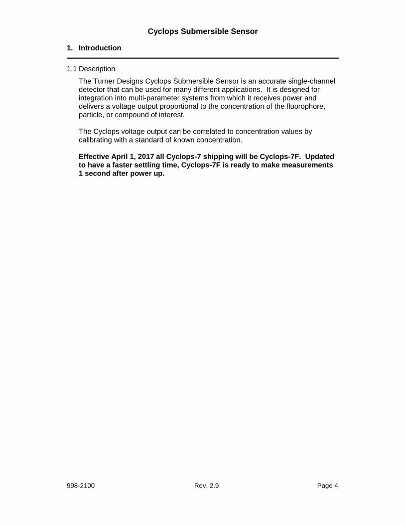
2.4 Functional Test for Cyclops with connector
To perform a functional check on the Cyclops, connect the Pigtail colored wires to the power supply and multi-meter as shown in Figure 1 below.
Additional Equipment required for functional tests:
DC Power Supply, 3 - 15 VDC, >100 mA Multi-meter to read 0 – 5 VDC
Note: Supply voltages greater than 15 VDC will result in damage to the sensor.
Figure 1.
With the Cyclops connected as shown in Figure 1 answer questions 1-3 by making the following functional tests:
1. Is the LED on?
Hold a piece of white paper about ½ an inch in-front of the optical head to ensure the LED is on. Note: Cannot perform this test for Turbidity sensors because they use IR which is not visible.
2. Is there voltage output?
The multi-meter should be reading some voltage >0 VDC
3. Does the voltage output change? Move the light source closer to your hand or a surface and check if the voltage output increases
Cyclops Pigtail cable holes
3
6
4
21
5 5
2
44
61
3
Cyclops pins / wires
3
4
21
5
66
Cyclops Pigtail cable holes
3
6
4
21
5 5
2
44
61
3 33
66
44
221
55 5
2
44
61
3
Cyclops pins / wires
3
4
21
5
66
Cyclops pins / wires
3
4
21
5
66
3
4
21
5
66
33
44
221
55
66
Cyclops Pigtail cable holes
3
6
4
21
5 5
2
44
61
3 33
66
44
221
55 5
2
44
61
3
Cyclops pins / wires
3
4
21
5
66
Cyclops pins / wires
3
4
21
5
66
33
44
221
55
66
Cyclops Pigtail cable holes
33
66
44
221
55 5
2
44
61
3 33
66
44
221
55 5
2
44
61
3
Cyclops pins / wires
3
4
21
5
66
3
4
21
5
66
33
44
221
55
66
Cyclops pins / wires
3
4
21
5
66
33
44
221
55
66
33
44
221
55
66
33
44
221
55
66
12.00 .015
+ -
DC Power Supply
PSU Positive Connection
(Red)
Supply Ground
0 VDC (Black)
3.52
Multimeter
10 VDC
+ -
Signal Output
“+” (White)
Analog Ground
“-” (Green)
Blue
(Tie to Green for 10X)
Brown
(Tie to Green for 100X)
X1(Low) Gain
Leave both wires disconnected
for Functional Check
Cyclops Pigtail Cable
12.00 .015
+ -
DC Power Supply
12.00 .015
+ -
DC Power Supply
PSU Positive Connection
(Red)
Supply Ground
0 VDC (Black)
3.52
Multimeter
10 VDC
+ -
3.52
Multimeter
10 VDC
+ -
Signal Output
“+” (White)
Analog Ground
“-” (Green)
Blue
(Tie to Green for 10X)
Brown
(Tie to Green for 100X)
X1(Low) Gain
Leave both wires disconnected
for Functional Check
Cyclops Pigtail Cable

Cyclops Submersible Sensor
998-2100 Rev. 2.9 Page 8
3. Measurements with the Cyclops
3.1 Introduction
The following information will describe how to:
o Determine and set the appropriate gain o Calibrate the Cyclops using standards with known concentrations o Make measurements with the Cyclops o Use the Solid Secondary Standard
Note: To make accurate and repeatable measurements it is important to keep the sensor clean; see section 4.1 for information on cleaning your sensor.
3.2 Setting the Gain
Gain setting refers to the sensitivity configuration of the sensor. There are three gain settings; X1, X10 and X100. As the gain increases, the sensitivity increases and the concentration range decreases.
3.2.1 Gain Determination Procedure
1) For in vivo applications, take a natural sample of water from a sampling station where you plan to deploy the Cyclops. Applying good measurement practices, store it properly and quickly transport it to a laboratory where you have the Cyclops connected to a multi meter and DC power source (see Figure 1).
2) Pour the water sample into a clean glass beaker and submerge the
optical end of the Cyclops (see Appendix B for “Recommended Measurement Practices for using your Cyclops in the Lab” for how best to accomplish these steps).
3) Activate the X10 gain setting (see Wiring Guide Appendix C) if you
believe the sample to represent a typical condition. You would like to obtain a signal from the sample that is significantly higher than a blank sample (de-ionized water or filtered seawater), but not a signal that is close to the maximum of 5 Volts.
4) If the sample signal is high, (>3.0 V for example) you may choose to
use the X1 gain instead of the X10 gain setting so that you avoid going over scale once you deploy the Cyclops.
5) If the sample signal is very low (<0.3V) you may choose to use the
X100 gain setting to achieve higher sensitivity but a smaller measurable range
This process is easier for dye tracing applications. Simply create the dye dilution of interest and record what signal level it provides on the three gain settings.

Cyclops Submersible Sensor
998-2100 Rev. 2.9 Page 9
3.2.2 Static Gain Control
If integrating into a multi parameter system or data logger that is set up for “Static Gain Control”, which refers to the use of only one gain setting at a time, then you must determine which gain to use prior to deployment (see section 3.2.1) and have an integration cable made to activate that specific gain (see Appendix C). For most applications the X10 gain will provide the best sensitivity, range, and resolution.
Customers wanting to dynamically change the gain ranges to achieve the optimum operating range should refer to “Method 2 – Dynamic Gain Control” in Appendix E on how to interface with a Data Collection System with programmable outputs.
3.2.3 Auto Gaining
Certain data loggers or multi parameter systems will have an auto gaining feature which will automatically adjust the sensitivity according to the voltage output from the Cyclops sensor. This feature maximizes the performance of Cyclops sensors allowing users to detect a broad range of concentrations, obtain the best resolution, and read minimum detection limits without having to rewire or manually change the sensor’s sensitivity. Turner Designs manufactures the DataBank Handheld Data Logger (see Appendix H) which has the auto gain feature and other functions that maximize the performance of Cyclops sensors.
3.3 Direct Concentration Calibration
Calibrating the Cyclops is a simple process requiring the use of calibration standards. The Cyclops can be calibrated using a single calibration standard which correlates the standard’s known concentration to the voltage measured for that specific standard:
1) Connect the Cyclops to a power source and set the Cyclops to a gain setting
(see section 3.2.1 for explanation on how to determine gain) 2) Measure the voltage from a blank sample for the configured gain setting.
Note: A good blank to use for this application is ultra pure or deionized water.
3) Use a standard of known concentration and create a correlation between the
standard’s concentration and the sensor’s voltage response.

Cyclops Submersible Sensor
998-2100 Rev. 2.9 Page 10
4) Once a correlation has been made, use the following equation to calculate concentration estimates for the calibrated gain: CSample = [(CStd)/(VoltsStd - VoltsBlank)] * (VoltsSample – VoltsBlank)
CStd = Concentration value of standard used for calibration Csample = Concentration of sample VoltsStd = Voltage reading from standard concentration VoltsSample= Voltage reading from sample(s) VoltsBlank = Voltage reading from blank
3.3.1 Direct Concentration Calibration for Chlorophyll Cyclops
Turner Designs sells Cyclops Chlorophyll Standard Solution, Blue Excitation P/N 2100-320 for direct concentration calibration. This standard represents an equivalent chlorophyll concentration of 40 µg/L. Follow instructions in section 3.3 to establish a correlation between the standard and the sensor’s voltage response. Use the equation from step 4 of section 3.3 to calculate chlorophyll estimates as µg/L in the calibrated gain.
Note: This calibration is an approximation. Actual µg/L estimates will vary depending on factors such as speciation, light history, algal stresses, pigment ratios, etc.
3.3.2 Direct Concentration Calibration for Turbidity Cyclops
Turner Designs recommends Amco Clear Turbidity Standards. They are non-toxic safe solutions consisting mainly of deionized water that comes prepared in a broad range of concentrations and have a shelf life guaranteed for one year. These standards, optimized for the Cyclops, are available from GFS Chemicals under part numbers 8506 (10 NTU), 8507 (100 NTU), and 8620 (1000 NTU). Follow instructions below to establish a correlation between the standard’s concentration and the sensor’s voltage response. Use the equation from step 4 of Section 3.3 to calculate turbidity values in NTU for the calibrated gain.
Cyclops Submersible Sensor
998-2100 Rev. 2.9 Page 11
4. Maintenance and Warranty
4.1 Maintenance
4.1.1 Rinsing
The Cyclops should be rinsed or soaked in fresh water following each deployment, ideally until it is completely clean again.
4.1.2 Care for the bulkhead connector
A light coat of Silicone spray should be used on the rubber of the male pins of the bulkhead to aid in sealing. The manufacturer recommends 3M™ Silicone Lubricant Spray or Loctite 8021 spray. Note: You should avoid using silicone grease. Do NOT use WD-40, it will destroy the connectors.
4.1.3 Care for the optics
The optical window should be visually inspected after each deployment following a soaking in fresh water. If cleaning is needed, use optical tissue to clean the window with soapy water. Note: The Cyclops should NOT come in contact with any organic solvents (i.e. acetone, methanol) or strong acids and bases. The UV Cyclops models are the ONLY Cyclops sensors that can be calibrated with Quinine Sulfate standards made in Hydrosulfuric Acid. All other Cyclops models CANNOT be used in Hydrosulfuric Acid.
4.2 Warranty Terms
Turner Designs warrants the Cyclops and accessories to be free from defects in materials and workmanship under normal use and service for a period of 12 months from the date of shipment from Turner Designs with the following restrictions:
Turner Designs is not responsible for replacing parts damaged by accident or neglect. Your instrument must be installed according to instructions in the User’s Manual. Damage from corrosion is not covered. Damage caused by customer modification of the instrument is not covered.
This warranty covers only Turner Designs products and is not extended to equipment used with our products. We are not responsible for incidental or consequential damages, except in those states where this limitation is not allowed. This warranty gives you specific legal rights and you may have other rights which vary from state to state.
Damage incurred in shipping is not covered.

Cyclops Submersible Sensor
998-2100 Rev. 2.9 Page 12
4.3 Warranty Service
To obtain service during the warranty period, the owner shall take the following steps:
1. Write, email or call Turner Designs Technical Support and describe as
precisely as possible the nature of the problem.
Phone: 1 (877) 316-8049 Email: [email protected]
2. Carry out any adjustments or tests as suggested by Technical Support. 3. If proper performance is not obtained you will be issued a Return Materials
Authorization number (RMA) to reference. Package the unit, write the RMA number on the outside of the shipping carton, and ship the instrument, prepaid, to Turner Designs. If the failure is covered under the warranty terms the instrument will be repaired and returned free of charge, for all customers in the contiguous continental United States.
For customers outside of the contiguous continental United States who purchased equipment from one of our authorized distributors, contact the distributor. If you purchased directly, contact us. We will repair the instrument at no charge. Customer pays for shipping, duties, and documentation to Turner Designs. Turner Designs pays for return shipment (custom duties, taxes and fees are the responsibility of the customer).
4.4 Out-of-Warranty Service
Follow steps for Warranty Service as listed above. If Technical Support can assist you by phone or correspondence, we will be glad to, at no charge. Repair service will be billed on a fixed price basis, plus any applicable duties and/or taxes. Shipment to Turner Designs should be prepaid. Your bill will include return shipment freight charges.
Address for Shipment:
Turner Designs, Inc. 1995 N. 1st Street
San Jose, CA 95112
Cyclops Submersible Sensor
998-2100 Rev. 2.9 Page 13
Cyclops Submersible Sensor
998-2100 Rev. 2.9 Page 14
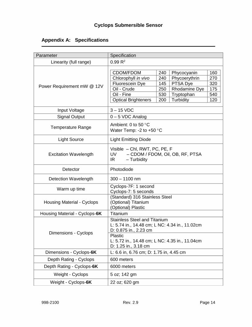
Appendix A: Specifications
Parameter Specification
Linearity (full range) 0.99 R2
Power Requirement mW @ 12V
CDOM/FDOM 240 Phycocyanin 160
Chlorophyll in vivo 240 Phycoerythrin 270
Fluorescein Dye 145 PTSA Dye 320
Oil - Crude 250 Rhodamine Dye 175
Oil - Fine 530 Tryptophan 540
Optical Brighteners 200 Turbidity 120
Input Voltage 3 – 15 VDC
Signal Output 0 – 5 VDC Analog
Temperature Range Ambient: 0 to 50 C
Water Temp: -2 to +50 C
Light Source Light Emitting Diode
Excitation Wavelength Visible – Chl, RWT, PC, PE, F UV – CDOM / FDOM, Oil, OB, RF, PTSA IR – Turbidity
Detector Photodiode
Detection Wavelength 300 – 1100 nm
Warm up time Cyclops-7F: 1 second Cyclops-7: 5 seconds
Housing Material - Cyclops (Standard) 316 Stainless Steel (Optional) Titanium (Optional) Plastic
Housing Material - Cyclops-6K Titanium
Dimensions - Cyclops
Stainless Steel and Titanium L: 5.74 in., 14.48 cm; L NC: 4.34 in., 11.02cm D: 0.875 in., 2.23 cm
Plastic L: 5.72 in., 14.48 cm; L NC: 4.35 in., 11.04cm D: 1.25 in., 3.18 cm
Dimensions - Cyclops-6K L: 6.6 in, 6.76 cm; D: 1.75 in, 4.45 cm
Depth Rating - Cyclops 600 meters
Depth Rating - Cyclops-6K 6000 meters
Weight - Cyclops 5 oz; 142 gm
Weight - Cyclops-6K 22 oz; 620 gm

Cyclops Submersible Sensor
998-2100 Rev. 2.9 Page 15
Appendix B: Recommended Measurement Practices
Recommended Lab Practices for Measurements The following steps will improve the accuracy and repeatability of your measurements, especially at low concentration levels: 1. Use a non-fluorescent container for your water samples. Note: Plastic may
fluoresce and interfere with the sample’s fluorescence. 2. If using a glass container, place the container on a non-reflective black surface. 3. Ensure that the sensor is more than 3 inches above the bottom of the container. 4. Ensure that the sensor is in the center of the container and has more than 2 inches
clearance between the cirumference of the sensor and the inside surface of the beaker.
>3
inches
Dark/Black
Non-Reflective
Surface
>2 inches all
round
Calibrated
Sensor
No Air Bubbles
On Optical
Surface
Glass Beaker
>3
inches
Dark/Black
Non-Reflective
Surface
>2 inches all
round
>2 inches all
round
Calibrated
Sensor
No Air Bubbles
On Optical
Surface
Glass Beaker

Cyclops Submersible Sensor
998-2100 Rev. 2.9 Page 16
Appendix C: Wiring Guide
Cyclops Wire
Pin Number
Function Connection
Red 1 Supply Voltage
3 – 15 VDC PSU – Positive Connection
Black 2 Supply Ground, 0VDC PSU – Ground Connection
Orange 3 Signal Out to data logger “+”
0 – 5VDC Multimeter Positive
Connection
Green 4 Analog Ground “-”,
0 VDC Multimeter Negative
Connection
Blue 5 X10 Gain, (Medium Sensitivity) See table below
Yellow 6 X100 Gain, (High Sensitivity) See table below
Gain Switching Table
Gain 10 (Blue)
Gain 100 (Brown)
Gain
Not connected Not connected X 1
Connected to analog ground
Not connected X 10
Not connected Connected to analog ground
X 100
Cyclops Pigtail cable holes
3
6
4
2
1
5 5
2
44
61
3
Cyclops pins / wires
3
4
21
5
66
Cyclops Pigtail cable holes
3
6
4
2
1
5 5
2
44
61
3 33
66
44
22
1
55 5
2
44
61
3
Cyclops pins / wires
3
4
21
5
66
3
4
21
5
66
33
44
221
55
66
Cyclops Submersible Sensor
998-2100 Rev. 2.9 Page 17
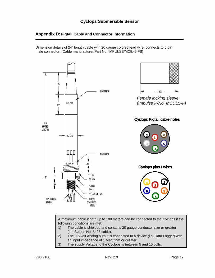
Appendix D: Pigtail Cable and Connector Information
Dimension details of 24” length cable with 20 gauge colored lead wire, connects to 6 pin male connector. (Cable manufacturer/Part No: IMPULSE/MCIL-6-FS)
Female locking sleeve,
(Impulse P/No. MCDLS-F)
A maximum cable length up to 100 meters can be connected to the Cyclops if the
following conditions are met:
1) The cable is shielded and contains 20 gauge conductor size or greater
(i.e. Beldon No. 8426 cable).
2) The 0-5 volt Analog output is connected to a device (i.e. Data Logger) with
an input impedance of 1 MegOhm or greater.
3) The supply Voltage to the Cyclops is between 5 and 15 volts.
Cyclops Pigtail cable holes
3
6
4
21
5 5
2
44
61
3
Cyclops Pigtail cable holes
3
6
4
21
5 5
2
44
61
3 33
66
44
221
55 5
2
44
61
3
Cyclops Pigtail cable holes
3
6
4
21
5 5
2
44
61
3 33
66
44
221
55 5
2
44
61
3
Cyclops Pigtail cable holes
33
66
44
221
55 5
2
44
61
3 33
66
44
221
55 5
2
44
61
3
Cyclops pins / wires
3
4
21
5
66
Cyclops pins / wires
3
4
21
5
66
Cyclops pins / wires
3
4
21
5
66
3
4
21
5
66
33
44
221
55
66
Cyclops pins / wires
3
4
21
5
66
Cyclops pins / wires
3
4
21
5
66
33
44
221
55
66
Cyclops pins / wires
3
4
21
5
66
3
4
21
5
66
33
44
221
55
66
Cyclops pins / wires
3
4
21
5
66
33
44
221
55
66
33
44
221
55
66
33
44
221
55
66
Cyclops Pigtail cable holes
3
6
4
21
5 5
2
44
61
3
Cyclops Pigtail cable holes
3
6
4
21
5 5
2
44
61
3 33
66
44
221
55 5
2
44
61
3
Cyclops Pigtail cable holes
3
6
4
21
5 5
2
44
61
3 33
66
44
221
55 5
2
44
61
3
Cyclops Pigtail cable holes
33
66
44
221
55 5
2
44
61
3 33
66
44
221
55 5
2
44
61
3
Cyclops Pigtail cable holes
3
6
4
21
5 5
2
44
61
3 33
66
44
221
55 5
2
44
61
3
Cyclops Pigtail cable holes
33
66
44
221
55 5
2
44
61
3 33
66
44
221
55 5
2
44
61
3
Cyclops Pigtail cable holes
33
66
44
221
55 5
2
44
61
3 33
66
44
221
55 5
2
44
61
3
Cyclops Pigtail cable holes
33
66
44
221
55 5
2
44
61
3 33
66
44
221
55 5
2
44
61
3
Cyclops pins / wires
3
4
21
5
66
Cyclops pins / wires
3
4
21
5
66
Cyclops pins / wires
3
4
21
5
66
3
4
21
5
66
33
44
221
55
66
Cyclops pins / wires
3
4
21
5
66
Cyclops pins / wires
3
4
21
5
66
33
44
221
55
66
Cyclops pins / wires
3
4
21
5
66
3
4
21
5
66
33
44
221
55
66
Cyclops pins / wires
3
4
21
5
66
33
44
221
55
66
33
44
221
55
66
33
44
221
55
66
Cyclops pins / wires
3
4
21
5
66
Cyclops pins / wires
3
4
21
5
66
33
44
221
55
66
Cyclops pins / wires
3
4
21
5
66
3
4
21
5
66
33
44
221
55
66
Cyclops pins / wires
3
4
21
5
66
33
44
221
55
66
33
44
221
55
66
33
44
221
55
66
Cyclops pins / wires
3
4
21
5
66
33
44
221
55
66
Cyclops pins / wires
33
44
221
55
66
33
44
221
55
66
Cyclops pins / wires
3
4
21
5
66
33
44
221
55
66
33
44
221
55
66
33
44
221
55
66
Cyclops pins / wires
33
44
221
55
66
33
44
221
55
66
33
44
221
55
66
33
44
221
55
66
Cyclops Submersible Sensor
998-2100 Rev. 2.9 Page 18
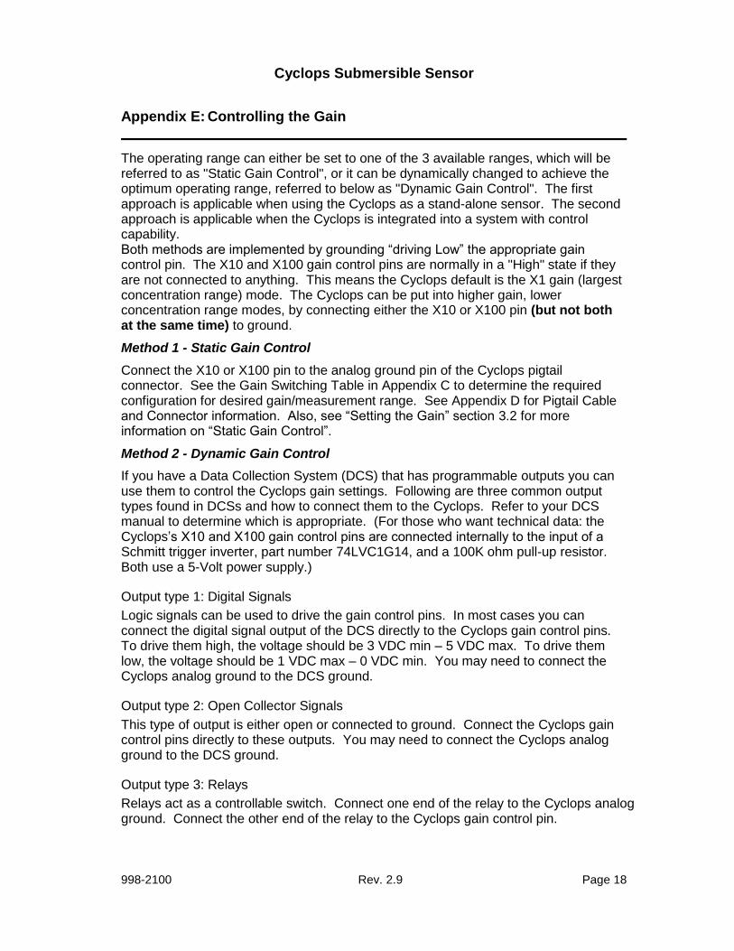
Appendix E: Controlling the Gain
The operating range can either be set to one of the 3 available ranges, which will be referred to as "Static Gain Control", or it can be dynamically changed to achieve the optimum operating range, referred to below as "Dynamic Gain Control". The first approach is applicable when using the Cyclops as a stand-alone sensor. The second approach is applicable when the Cyclops is integrated into a system with control capability. Both methods are implemented by grounding “driving Low” the appropriate gain control pin. The X10 and X100 gain control pins are normally in a "High" state if they are not connected to anything. This means the Cyclops default is the X1 gain (largest concentration range) mode. The Cyclops can be put into higher gain, lower concentration range modes, by connecting either the X10 or X100 pin (but not both at the same time) to ground.
Method 1 - Static Gain Control
Connect the X10 or X100 pin to the analog ground pin of the Cyclops pigtail connector. See the Gain Switching Table in Appendix C to determine the required configuration for desired gain/measurement range. See Appendix D for Pigtail Cable and Connector information. Also, see “Setting the Gain” section 3.2 for more information on “Static Gain Control”.
Method 2 - Dynamic Gain Control
If you have a Data Collection System (DCS) that has programmable outputs you can use them to control the Cyclops gain settings. Following are three common output types found in DCSs and how to connect them to the Cyclops. Refer to your DCS manual to determine which is appropriate. (For those who want technical data: the Cyclops’s X10 and X100 gain control pins are connected internally to the input of a Schmitt trigger inverter, part number 74LVC1G14, and a 100K ohm pull-up resistor. Both use a 5-Volt power supply.)
Output type 1: Digital Signals
Logic signals can be used to drive the gain control pins. In most cases you can connect the digital signal output of the DCS directly to the Cyclops gain control pins. To drive them high, the voltage should be 3 VDC min – 5 VDC max. To drive them low, the voltage should be 1 VDC max – 0 VDC min. You may need to connect the Cyclops analog ground to the DCS ground.
Output type 2: Open Collector Signals
This type of output is either open or connected to ground. Connect the Cyclops gain control pins directly to these outputs. You may need to connect the Cyclops analog ground to the DCS ground.
Output type 3: Relays
Relays act as a controllable switch. Connect one end of the relay to the Cyclops analog ground. Connect the other end of the relay to the Cyclops gain control pin.

Cyclops Submersible Sensor
998-2100 Rev. 2.9 Page 19
Appendix F: Linear Range, Quenching and Temperature Considerations
The linear range is the concentration range in which the fluorometer’s output is directly proportional to the concentration of the signal. The linear range begins with the smallest detectable concentration and spans to an upper limit (concentration) that is dependent upon the properties of the material, filters used, and path length.
A non-linear relationship is seen at very high concentrations where the signal does not increase at a constant rate in comparison to the change in concentration (see figure below). At even higher concentrations, the signal will decrease even though the sample concentrations are continuing to increase. This effect is known as “signal quenching”.
Linearity can be checked by diluting a sample 1:1 or some other convenient ratio. If the sample is still in the linear range, the reading will decrease in direct proportion to the dilution. If the reading does not decrease in direct proportion to the dilution, or if the reading increases, the sample is beyond the linear range.
Temperature Considerations
Fluorescence is temperature sensitive. As the temperature of the sample increases, the fluorescence decreases. For greatest accuracy, record the sample temperature and correct the sensor output for changes in temperature.
For further information on how temperature, light, water quality and the physiological state of the algal cells can all affect the measurement of chlorophyll, please refer to the application section of Turner Designs’ website.
Graph showing Linear and
Quenching Regions of the sample’s response
Sample Concentration
Flu
oro
me
ter
Rea
din
g
Fluorometer Response Curve
Sample
Quenching Region
Sample
Linear Region
Graph showing Linear and
Quenching Regions of the sample’s response
Sample Concentration
Flu
oro
me
ter
Rea
din
g
Fluorometer Response Curve
Sample
Quenching Region
Sample
Linear Region
Sample Concentration
Flu
oro
me
ter
Rea
din
g
Fluorometer Response Curve
Sample
Quenching Region
Sample
Linear Region

Cyclops Submersible Sensor
998-2100 Rev. 2.9 Page 20
Appendix G: Functional Test for Cyclops with no Connector
To perform a functional check on the Cyclops, connect the Cyclops colored wires to the power supply and multi-meter as shown in Figure 2 below.
No Connector Cyclops (P/N: 2110/2100-000-“Identification Letter”-NC) Additional Equipment required for functional tests:
DC Power Supply, 3 - 15 VDC, >100 mA Multi-meter to read 0 – 5 VDC
Note: Supply voltages greater than 15 VDC will result in damage to the sensor.
Figure 2.
With the Cyclops connected as shown in Figure 2 answer questions 1-3 by making the following functional tests:
1. Is the LED on?
Hold a piece of white paper about ½ an inch in-front of the optical head to ensure the LED is on. Note: Cannot perform this test for Turbidity sensors because they use IR which is not visible.
2. Is there voltage output?
The multi-meter should be reading some voltage >0 VDC
3. Does the voltage output change? Move the light source closer to your hand or a surface and check if the voltage output increases
12.00 .015
+ -
DC Power Supply
LED
Light
Output
PSU Positive Connection
(Red)
Supply Ground
0 VDC (Black)
3.52
Multimeter
10 VDC
+ -
Signal Output
“+” (Orange)
Analog Ground
“-” (Green)
Blue
(Tie to Green for 10X)
Yellow
(Tie to Green for 100X)
X1(Low) Gain
Leave both wires disconnected
for Functional Check
Cyclops pins / wires
3
4
2
1
5
66
Cyclops pins / wires
33
44
22
1
55
66
12.00 .015
+ -
DC Power Supply
12.00 .015
+ -
DC Power Supply
LED
Light
Output
LED
Light
Output
PSU Positive Connection
(Red)
Supply Ground
0 VDC (Black)
3.52
Multimeter
10 VDC
+ -
3.52
Multimeter
10 VDC
+ -
Signal Output
“+” (Orange)
Analog Ground
“-” (Green)
Blue
(Tie to Green for 10X)
Yellow
(Tie to Green for 100X)
X1(Low) Gain
Leave both wires disconnected
for Functional Check
Cyclops pins / wires
3
4
2
1
5
66
Cyclops pins / wires
33
44
22
1
55
66
Cyclops Submersible Sensor
998-2100 Rev. 2.9 Page 21
Appendix H: Using the Cyclops Submersible Sensor with the DataBank
Cyclops sensors are analog output devices that produce a 0 – 5 volt signal that is proportional to the fluorophore being measured. Turner Designs offers the DataBank, a universal handheld meter, datalogger, and power supply that can be used to maximize performance of Cyclops sensors with functions such as:
Auto gaining
User defined calibrations
Large internal memory
Interval logging
The DataBank comes with intuitive GUI software that allows users to easily calibrate, set up logging, download data, and define parameters and values necessary to help configure the Cyclops for a specific application or study. Available options include GPS capability, external power, travel case, and car charger.
DataBank uses for different sampling protocols: Multiple Site Measurements – measure fluorescence at different locations within your water system or across many systems; GPS enabled units provide latitude/longitude data per location
Profiling – purchase extended cables to allow for vertical profiling
Monitoring – deploy the Cyclops to a fixed location or depth and monitor the signal over time; set up logging to capture a signal within a specific time frame; download data while the sensor is deployed and continuously measuring; set up digital data output via HyperTerminal
For any application or sampling protocol, the DataBank facilitates and maximizes performance of all Cyclops sensors allowing versatility and flexibility in calibration, setup, and measurement.
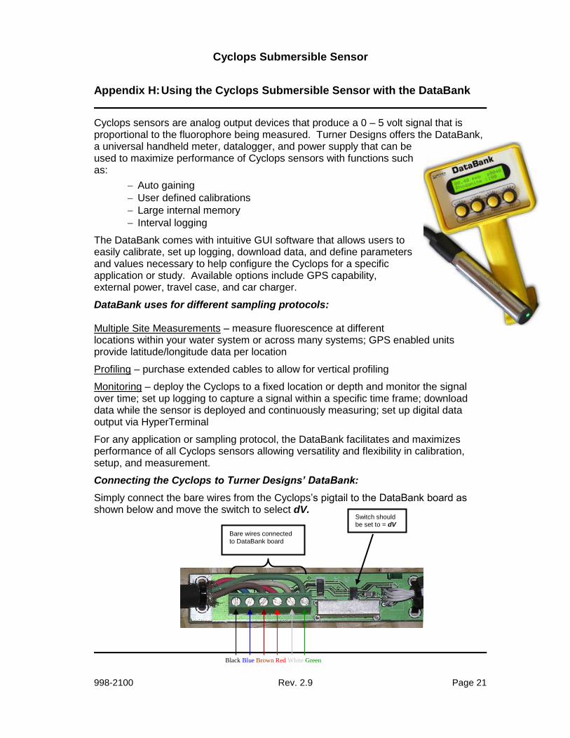
Connecting the Cyclops to Turner Designs’ DataBank:
Simply connect the bare wires from the Cyclops’s pigtail to the DataBank board as shown below and move the switch to select dV.
Black Blue Brown Red White Green
Switch should be set to = dV
Bare wires connected
to DataBank board