User's Manual Manual del Usuario Manual do Usuário€¦ · user manual and the parameters quick...
142
User's Manual Manual del Usuario Manual do Usuário Series: CFW700 English / Español / Português Document: 10000771684 / 01 Models/Modelos: Sizes A...E Mec A...E Date/Data: 10/2010
Transcript of User's Manual Manual del Usuario Manual do Usuário€¦ · user manual and the parameters quick...

User's Manual
Manual del Usuario
Manual do Usuário
Series: CFW700
English / Español / Português
Document: 10000771684 / 01
Models/Modelos: Sizes A...E
Mec A...E
Date/Data: 10/2010

ATTENTION!
Parameters P0296 (Rated Line Voltage), P0400 (Rated Motor Voltage) and
P0403 (Rated Motor Frequency), were readjusted at the:
200...240 V/220-230 V (S2, B2 y T2) models: P0296=0 (200-240 V), P0400=220
V and P0403=60 Hz;
380...480 V (T4) models: P0296=3 (440/460 V), P0400=440 V and
P0403=60 hz.
For different values of line reted voltage and/or motor voltage ans frequency,
set these parameters through the STARTUP menu, as presented in the user
manual section 5.2 - START-UP.
¡ATENCIÓN!
Los parámetros P0296 (Tensión Nominal Red), P0400 (Tensión Nominal del
Motor) y P0403 (Frecuencia Nominal del Motor) fueran ajustados en:
modelos 220...240 V/220-230 V (S2, B2 y T2): P0296=0 (200-240 V), P0400=220
V y P043=60 Hz;
modelos 380...480 V (T4): P0296=3 (440/460 V), P0400=440 V y P0403=60
Hz.
Para valores diferente de tensión nominal de la red y/o tensión y frecuencia
nominales del motor, ajustar estos parámetro vía menú SATRUP, conforme
presentado en el ítem 5.2 - Puesta en Marcha, de ese manual.
ATENÇÃO!
Os parâmetros P0296 (Tensão Nominal de Rede), P0400 (Tensão Nominal do
Motor) e P0403 (Frequência Nominal do Motor) foram ajustados em:
modelos 380...240 V/200-230 V (S2, B2 e T2): P0296=0 (200-240 V), P0400=220
V e P0403=60 Hz;
modelos 380...480 V (T4): P0296=3 (440-460 V), P0400=440 V e P0403=60
Hz.
Para valores diferente de tensão nominal da rede e/ou tensão de frequência
nominais do motor, ajustar esses parâmentros via menu STARTUP, conforme
apresentado no item 5.2 - Colocação em Funcionamento, deste manual.

Summary of Revisions / Sumario de las Revisiones / Sumário de Revisões
The table below describes the revisions made to this manual.
Revision Description Chapter
01 First Edition -
La información a seguir describe las revisiones ocurridas en este manual.
Revisión Descripción Capítulo
01 Primera Edición -
A informação abaixo descreve as revisões ocorridas neste manual.
Revisão Descrição Capítulo
01 Primeira edição -


Summary
- English -
Summary
1. SAFETY INSTRUCTIONS.................................................................71.1 SAFETY WARNINGS IN THE MANUAL..................................................7
1.2 SAFETY WARNINGS IN THE PRODUCT ...............................................7
1.3 PRELIMINARY RECOMMENDATIONS..................................................8
2. GENERAL INSTRUCTIONS .............................................................92.1 ABOUT THE MANUAL ............................................................................9
2.2 ABOUT THE CFW700..............................................................................9
2.3 IDENTIFICATION ...................................................................................11
2.4 LIST OF AVAILABLE MODELS ............................................................12
2.5 IDENTIFICATION LABELS....................................................................12
2.6 RECEIVING AND STORAGE.................................................................13
3. INSTALLATION AND CONNECTION............................................. 143.1 MECHANICAL INSTALLATION.............................................................14
3.1.1 Installation Environment .............................................................14
3.1.2 Mounting Considerations...........................................................14
3.2 ELECTRICAL INSTALLATION ..............................................................15
3.2.1 Identification of the Power and Grounding Terminals............15
3.2.2 Power / Grounding Wiring and Fuses.......................................16
3.2.3 Power Connections.....................................................................17
3.2.3.1 Input Connections....................................................................17
3.2.3.2 Dynamic Braking (standard built-in for sizes A, B, C
and D and optional built-in for size E - CFW700...DB...) ..................18
3.2.3.3 Output Connections ................................................................19
3.2.4 Grounding Connections .............................................................20
3.2.5 Control Connections ..................................................................20
3.2.6 Cable Distances ..........................................................................23
3.3 INSTALLATION ACCORDING TO THE EUROPEAN DIRECTIVE
OF ELECTROMAGNETIC COMPATIBILITY ..............................................23
3.3.1 Conformal Installation ................................................................24
3.3.2 Emission and Immunity Levels..................................................24
4. KEYPAD (HMI) AND BASIC PROGRAMMING ............................254.1 INTEGRAL KEYPAD - HMI-CFW700....................................................25
4.2 APPLICATIONS......................................................................................28
4.2.1 PID Regulator Application..........................................................28
4.2.1.1 Academic PID ............................................................................31
4.2.2 Electronic Potentiometer (EP) Application .............................36
4.2.3 Multispeed Application .............................................................39
4.2.4 3-Wire Start/Stop Command Application................................42
4.2.5 Forward/Reverse Run Application............................................43
Summary
- English -
5. FIRST TIME POWER-UP AND START-UP....................................455.1 PREPARE FOR START-UP ....................................................................45
5.2 START-UP...............................................................................................45
5.2.1 Oriented Start-up Menu..............................................................46
5.2.2 Basic Application Menu ............................................................49
6. TROUBLESHOOTING AND MAINTENANCE ...............................506.1 FAULTS AND ALARMS..........................................................................50
6.2 SOLUTIONS FOR THE MOST FREQUENT PROBLEMS....................50
6.3 INFORMATION FOR CONTACTING TECHNICAL SUPPORT ............51
7. OPTION KITS AND ACCESSORIES ..............................................527.1 OPTION KITS..........................................................................................52
7.1.1 RFI Filter (only for sizes A, B, C and D) - CFW700...C3... .........52
7.1.2 Dynamic Braking IGBT (only for size E) - CFW700E...DB... ....52
7.1.3 Nema1 Protection Degree (only for sizes A, B, C and E) -
CFW700...N1... .......................................................................................52
7.1.4 IP21 Protection Degree (only for sizes A, B and C) -
CFW700...21...........................................................................................52
7.1.5 Safety Stop - CFW700...Y1... .......................................................52
7.1.6 24 Vdc External Control Power Supply - CFW700...W1... ........52
7.2 ACCESSORIES.......................................................................................52
8. TECHNICAL SPECIFICATIONS .....................................................548.1 POWER DATA.........................................................................................54
8.2 ELECTRICAL/GENERAL SPECIFICATIONS .......................................54
8.2.1 Codes and Standards .................................................................56
APPENDIX A - DIAGRAMS AND FIGURES ....................................165
APPENDIX B – TECHNICAL ESPECIFICATIONS........................... 173
CFW700 | 7 - English -
Safety Instructions
1. SAFETY INSTRUCTIONS
This manual provides information for the proper installation and operation of the CFW700
frequency inverter.
Only trained personnel, with proper qualifications, and familiar with this kind of equipment
and associated machinery shall plan and implement the installation, starting, operation, and
maintenance of this equipment. The personnel shall follow all the safety instructions described in
this manual and/or defined by the local regulations. Failure to comply with the safety instructions
may result in death, serious injury, and equipment damage.
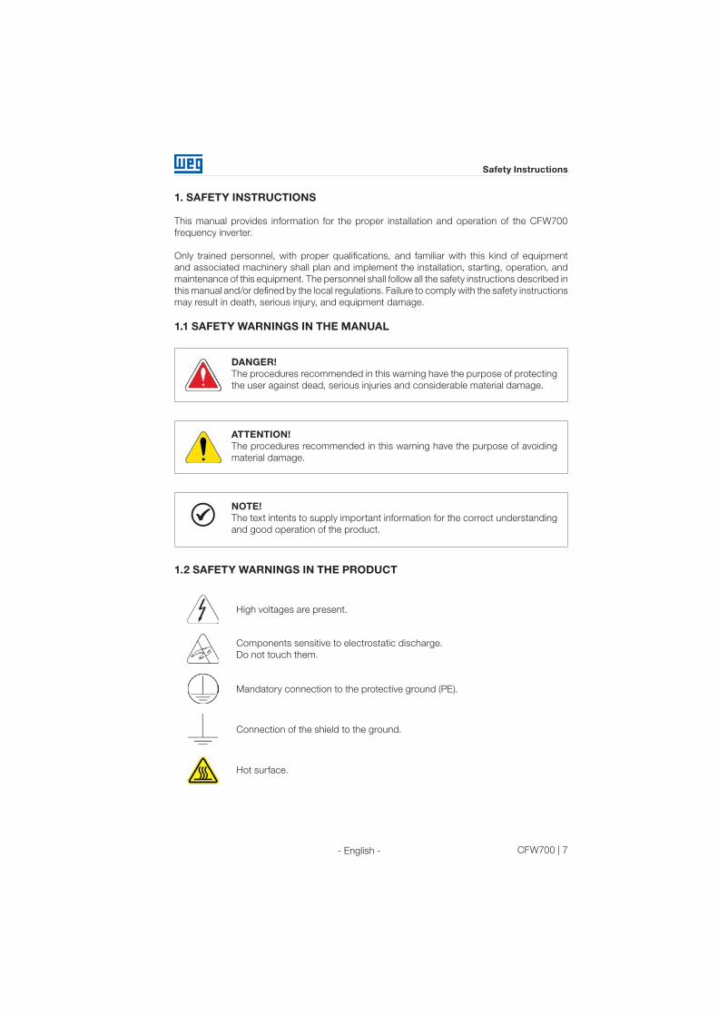
1.1 SAFETY WARNINGS IN THE MANUAL
DANGER!
The procedures recommended in this warning have the purpose of protecting
the user against dead, serious injuries and considerable material damage.
ATTENTION!
The procedures recommended in this warning have the purpose of avoiding
material damage.
NOTE!
The text intents to supply important information for the correct understanding
and good operation of the product.
1.2 SAFETY WARNINGS IN THE PRODUCT
High voltages are present.
Components sensitive to electrostatic discharge.
Do not touch them.
Mandatory connection to the protective ground (PE).
Connection of the shield to the ground.
Hot surface.

8 | CFW700 - English -
Safety Instructions
1.3 PRELIMINARY RECOMMENDATIONS
DANGER!
Always disconnect the main power supply before touching any electrical
device associated with the inverter. Several components may remain charged
with high voltage and/or in movement (fans), even after the AC power supply
has been disconnected or turned off. Wait at least 10 minutes to guarantee
the fully discharge of capacitors. Always connect the equipment frame to the
ground protection (PE).
NOTE!
Frequency inverters may cause interference in other electronic devices.
Follow the recommendations listed in Chapter 3 – Installation and
Connection, to minimize these effects.
Fully read this manual before installing or operating the inverter.
Do not perform a withstand voltage test on any part of the inverter!
If needed, please, consult WEG.
CFW700 | 9
General Instructions
- English -
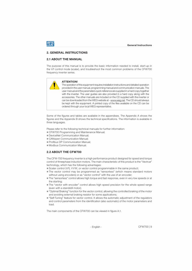
2. GENERAL INSTRUCTIONS
2.1 ABOUT THE MANUAL
The purpose of this manual is to provide the basic information needed to install, start-up in
the V/f control mode (scalar), and troubleshoot the most common problems of the CFW700
frequency inverter series.
ATTENTION!
The operation of this equipment requires installation instructions and detailed operation
provided in the user manual, programming manual and communication manuals. The
user manual and the parameters quick reference are supplied in a hard copy together
with the inverter. The user guides are also provided in a hard copy along with the
accessories. The other manuals are included on the CD supplied with the inverter or
can be downloaded from the WEG website at - www.weg.net. The CD should always
be kept with the equipment. A printed copy of the files available on the CD can be
ordered through your local WEG representative.
Some of the figures and tables are available in the appendixes. The Appendix A shows the
figures and the Appendix B shows the technical specifications. The information is available in
three languages.
Please refer to the following technical manuals for further information:
CFW700 Programming and Maintenance Manual;
DeviceNet Communication Manual;
CANopen Communication Manual;
Profibus DP Communication Manual;
Modbus Communication Manual.
2.2 ABOUT THE CFW700
The CFW-700 frequency inverter is a high performance product designed for speed and torque
control of threephase induction motors. The main characteristic of this product is the “Vectrue”
technology, which has the following advantages:
Scalar control (V/f), VVW, or vector control programmable in the same product;
The vector control may be programmed as “sensorless” (which means standard motors
without using encoders) or as “vector control” with the use of an encoder;
The “sensorless” control allows high torque and fast response, even in very low speeds or at
the starting;
The “vector with encoder” control allows high speed precision for the whole speed range
(even with a standstill motor);
“Optimal Braking” function for the vector control, allowing the controlled braking of the motor
and avoiding external braking resistor for some applications;
“Self-Tuning” feature for vector control. It allows the automatic adjustment of the regulators
and control parameters from the identification (also automatic) of the motor parameters and
load.
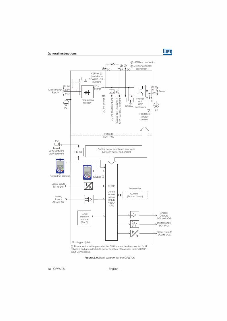
The main components of the CFW700 can be viewed in figure A.1.
10 | CFW700
General Instructions
- English -
Analog
Inputs
AI1 and AI2
FLASH
Memory
Module
(Slot 5)
Digital Inputs
DI1 to DI8
Control power supply and interfaces
between power and controlRS-485
PC
POWER
CONTROL
Three-phase
rectifier
C3Filter (*)
(available in
CFW700...C3...
inverters)
Motor
U/T1
V/T2
W/T3
DC+ DC-BR
Inverter
with
IGBT
transistors
Mains Power
Supply
R/L1/L
S/L2/N
T/L3
= DC bus connection
= Braking resistor
connection
Pre-
charge
WPS Software
WLP Software
DC
lin
k c
ho
kes
DC
lin
k c
ap
acito
r b
an
k
Bra
kin
g IG
BT (availa
ble
in
CF
W70
0...D
B... in
vert
ers
)
RFI filter
Keypad
CC700
Control
Board
with a
32 bits
"RISC"
CPU
Analog
Outputs
AO1 and AO2
Digital Output
DO1 (RL1)
Digital Outputs
DO2 to DO5
Keypad (remote)
Feedback:
- voltage
- current
PEPE
COMM 1
(Slot 3 - Green)
Accessories
= Keypad (HMI)
(*) The capacitor to the ground of the C3 filter must be disconnected for IT
networks and grounded delta power supplies. Please refer to item 3.2.3.1 -
Input Connections.
Figure 2.1: Block diagram for the CFW700

CFW700 | 11
General Instructions
- English -
2.3 IDENTIFICATION
Table 2.1: Identification of the CFW700 inverters
Product
and
series
Model Identification
Braking (1)
Enclosure (1)
Conducted
emission
level (1)
Safety
stop
(3)
External
control
voltage
Special
hardware
version
Special
software
versionSize
Rated
output
current
Number
of power
phases
Rated
voltage
Ex.: CFW700 A 03P6 T 4 DB 20 C3 Y1 W1 --- --
Availa
ble
op
tio
ns
CFW700
Refer to table 2.2.Blank =
standard.
NB = without dynamic braking (valid only for size
E inverters).
Sx =
special
software.
DB = with dynamic braking. Blank = standard.
20 = IP20 (2) Hxx or Kxx = special
hardware.
21 = IP21 (not available for size E inverters). Blank = not available.
N1 = Nema1 enclosure (UL Type 1) (protection degree according to
IEC: IP21 for sizes A, B and C and IP20 for sizes D and E).
W1 = 24 Vdc power supply,
independent of the control voltage.
Blank = not available.
Blank = it is not in accordance with the standard conducted emission levels.Y1 = with safety stop function according to
EN 954-1/ISO 13849-1, category 3.C3 = according to category 3 (C3) of IEC 61800-3, with built-in RFI filter.
Notes: (1) The options available for each model are shown in table 2.2.
(2) This option is not available for size D inverters (the standard product is Nema1).
(3) This option is not available for size A inverters with the N1 option (Nema1 enclosure) or IP21.
Table 2.2: Options available for each model according to the size, power supply, rated current and
voltage of the inverter
Size
Rated output
current for ND
overload
Number of
power phasesRated voltage
Available options for the remaining identification
codes of the inverters
(standard product is shown in bold)
Braking
Enclosure
(protection
degree)
Conducted emission
level
A06P0 = 6.0 A B = single-phase or
three-phase2 = 200…240 V DB 20, 21 or N1 Blank
07P0 = 7.0 A
A
06P0 = 6.0 A
S = Single-phase 2 = 200…240 V DB 20, 21 or N1C3
07P0 = 7.0 A
10P0 = 10 A Blank or C3
A
07P0 = 7.0 A
T = three-phase
2 = 200…240 V DB
20, 21 or N1
Blank or C3
10P0 = 10 A
13P0 = 13 A
16P0 = 16 A
B
24P0 = 24 A
28P0 = 28 A
33P5 = 33.5 A
C
45P0 = 45 A
54P0 = 54 A
70P0 = 70 A
D86P0 = 86 A
21 or N10105 = 105 A
E
0142 = 142 A
2 = 220…230 V NB or DB 20 or N1 C30180 = 180 A
0211 = 211 A
A
03P6 = 3.6 A
T = three-phase 4 = 380-480 V
DB
20, 21 or N1
Blank or C3
05P0 = 5.0 A
07P0 = 7.0 A
10P0 = 10 A
13P5 = 13.5 A
B
17P0 = 17 A
24P0 = 24 A
31P0 = 31 A
C
38P0 = 38 A
45P0 = 45 A
58P5 = 58.5 A
D70P5 = 70.5 A
21 or N188P0 = 88 A
E
0105 = 105 A
NB or DB 20 or N1 C30142 = 142 A
0180 = 180 A
0211 = 211 A

12 | CFW700
General Instructions
- English -
2.4 LIST OF AVAILABLE MODELS
The available inverter models are listed in table B.1 and B.2.
2.5 IDENTIFICATION LABELS
There are two nameplates on the CFW700: one complete nameplate is affixed to the side of the
inverter and a simplified one is located under the keypad. Please refer to figure A.2 to verify the
position of these labels on the product. The nameplate under the keypad allows the identification
of the most important characteristics of the inverter even if they are mounted side-by-side. When
there is more than one inverter it is necessary to be careful not to exchange the inverter covers
(front cover in case of inverters sizes A, B or C and control rack cover for inverters sizes D and
E) because there are individual information labels under the keypad of each inverter.
CFW700 model
Manufacturing dateWEG part number
Serial number
(a) Nameplate located under the keypad
CFW700 model
WEG part number
Manufacturing date
Inverter net weight
Input rated data (voltage,
number of phases, rated
currents for operation with
ND and HD overload cycles,
and frequency)
Output rated data
(voltage, number of
phases, rated currents for
operation with ND and HD
overload cycles, overload
currents for 1 min and 3 s,
and frequency range)
Maximum ambient
temperature (without
derating) for ND overload
with open spaces for
ventilation around the
inverter (refer to the
dimensions A, B, C and D
in figure B.8)
Serial number
Current specifications
for operation with normal
overload cycle (ND)
Current specifications
for operation with heavy
overload cycle (HD)
(b) Nameplate affixed to the side of the inverter
Figure 2.2 (a) and (b): Nameplates

CFW700 | 13
General Instructions
- English -
2.6 RECEIVING AND STORAGE
The CFW700 comes packaged in a cardboard box up to size C inverter models. The bigger
models are packed in wooden box. There is an identification label affixed to the outside of this
package, the same one that is affixed to the side of the CFW700 inverter.
Follow the steps below to open the packaging of models larger than size C:
1 - Put the shipping container over a flat and stable area with the assistance of another two
people;
2 - Open the wood crate;
3 - Remove all the packing material (the cardboard or styrofoam protection) before removing
the inverter.
Check the following items once the inverter is delivered:
Verify that the CFW700 nameplate corresponds to the model number on your purchase order;
Inspect the CFW700 for external damage during transportation.
Report any damage immediately to the carrier that delivered your CFW700 inverter.
If CFW700 is to be stored for some time before use, be sure that it is stored in a clean and dry
location that conforms to the storage temperature specification (between -25 °C and 60 °C (-13
°F and 140 °F)). Cover the inverter to prevent dust accumulation inside it.
ATTENTION!
Capacitor reforming is required if drives are stored for long periods of time
without power. Please follow the procedure at item Preventive Maintenance in
the Programming and Troubleshooting Manual of the CFW700.

14 | CFW700
Installation and Connection
- English -
3. INSTALLATION AND CONNECTION
3.1 MECHANICAL INSTALLATION
3.1.1 Installation Environment
Avoid installing the inverter in an area with:
Direct exposure to sunlight, rain, high humidity, or sea-air;
Inflammable or corrosive gases or liquids;
Excessive vibration;
Dust, metallic particles, and oil mist.
Environment conditions for the operation of the inverter:
Inverter surrounding temperature: from -10 ºC up to Ta according to the table B.3.
For temperatures around the inverter greater than Ta and smaller than 60 °C (sizes A, B, C
and D) and 55 °C (size E), it is necessary to apply current reduction of 2 % for every degree
Celsius (or 1.11 % each °F) up to Ta.
Humidity: from 5 % to 90 % non-condensing.
Altitude: up to 1000 m (3,300 ft) - standard conditions (no derating required).
From 1000 m to 4000 m (3,300 ft to 13,200 ft) - current derating of 1 % each 100 m (or 0.3
% each 100 ft) above 1000 m (3,300 ft) altitude.
From 2000 m to 4000 m (6,600 ft to 13,200 ft) above sea level - maximum voltage reduction
(240 V for 200...240 V models, 230 V for 220...230 V models and 480 V for 380...480 V models)
of 1.1 % for each 100 m (330 ft) above 2000 m (6,600 ft).
Pollution degree: 2 (according to EN50178 and UL508C) with non-conductive pollution.
Condensation shall not originate conduction through the accumulated residues.
3.1.2 Mounting Considerations
External dimensions, fixing holes position and net weight of the inverter are presented at figures
B.7 and B.8. Please refer to figures B.9 to B.13 for more details of each inverter size.
Install the inverter upright on a flat surface. First place the screws on the surface where the
drive is going to be installed, install the drive and then tighten the screws.
Size E inverters with N1 option (CFW700E...N1...):
After fixing the inverter, install the upper Nema 1 kit on the inverter using the two M8 screws
provided with the product.
Let the minimum clearances specified in figure B.8 in order to allow air circulation for cooling. It
is possible to assembly sizes A, B and C inverters with IP20 protection degree (CFW700… 20…)
side by side without lateral spacing, i.e., with the D distance presented in figure B.8 equal to zero.
Do not install heat sensitive components right above the inverter.
ATTENTION!
When arranging two or more inverters vertically, respect the minimum
clearance A + B (figure B.8) and provide an air deflecting plate so that the
heat rising up from the bottom inverter does not affect the top inverter.
Provide conduit for physical separation of the signal, control, and power
conductors (refer to item 3.2 - Electrical Installation).
CFW700 | 15
Installation and Connection
- English -
Please refer to figure B.8 for surface and flange mounting data. The inverter dissipated power
at rated condition for surface and flange mounting is presented in table B.3. Remove the drive
mounting brackets for flange mounting. The protection degree of the inverter outside the panel
is IP54 for flange mounting. It is necessary to provide proper seal for the opening where the
inverter is installed to ensure the protection degree of the panel. Example: sealing with silicone.
Please refer to figure A.4 for more details on the access to the control and power terminals.
3.2 ELECTRICAL INSTALLATION
DANGER!
The following information is merely a guide for proper installation. Comply
with applicable local regulations for electrical installations.
Make sure the AC power supply is disconnected before starting the
installation.
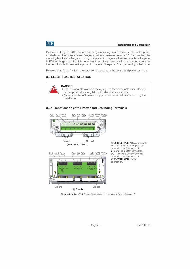
3.2.1 Identification of the Power and Grounding Terminals
GroundGround
R/L1 S/L2 T/L3 DC- DC+ U/T1 V/T2 W/T3BR
(a) Sizes A, B and C
Ground Ground
(b) Size D
R/L1 S/L2 T/L3 DC- DC+ U/T1 V/T2 W/T3BR
R/L1, S/L2, T/L3: AC power supply.
DC-: this is the negative potential
terminal in the DC bus circuit.
BR: braking resistor connection.
DC+: this is the positive potential
terminal in the DC bus circuit.
U/T1, V/T2, W/T3: motor
connection.
Figure 3.1 (a) and (b): Power terminals and grounding points – sizes A to E
16 | CFW700
Installation and Connection
- English -
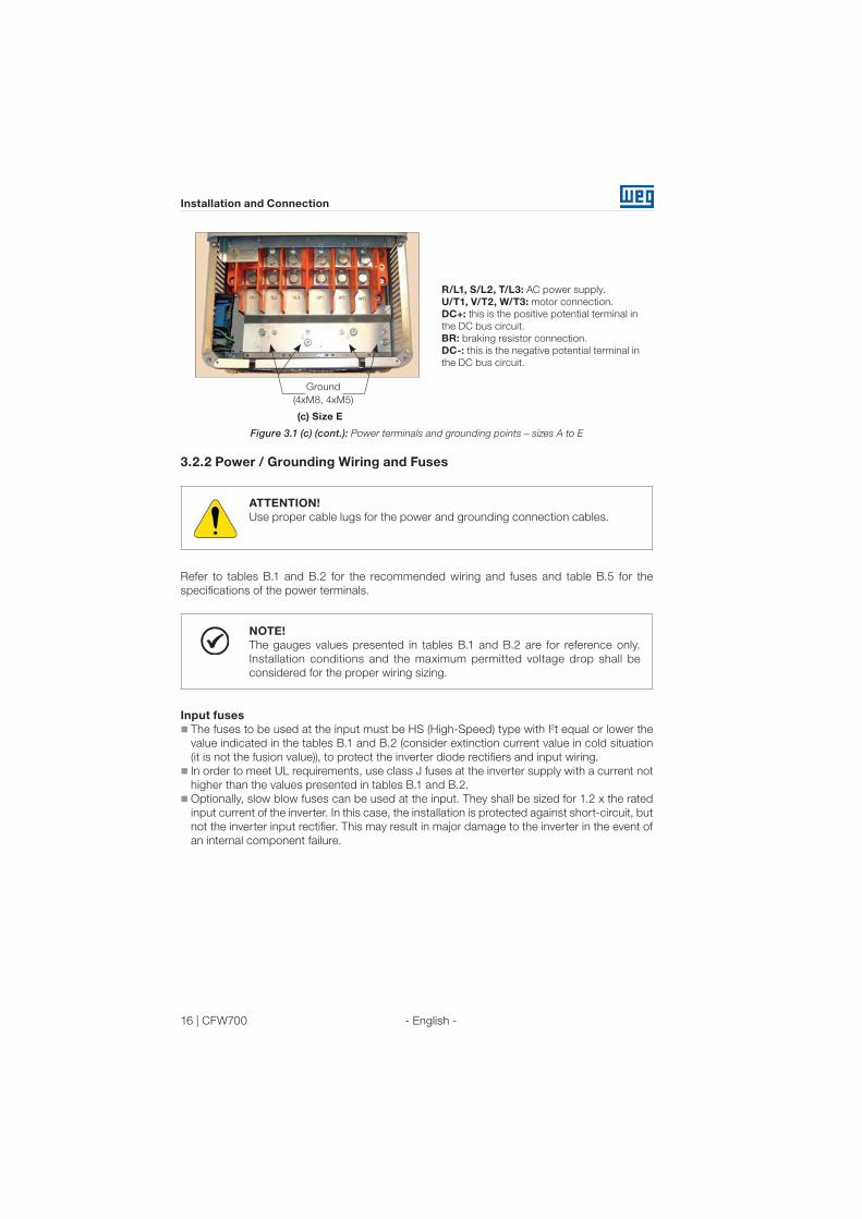
Ground
(4xM8, 4xM5)
(c) Size E
R/L1, S/L2, T/L3: AC power supply.
U/T1, V/T2, W/T3: motor connection.
DC+: this is the positive potential terminal in
the DC bus circuit.
BR: braking resistor connection.
DC-: this is the negative potential terminal in
the DC bus circuit.
Figure 3.1 (c) (cont.): Power terminals and grounding points – sizes A to E
3.2.2 Power / Grounding Wiring and Fuses
ATTENTION!
Use proper cable lugs for the power and grounding connection cables.
Refer to tables B.1 and B.2 for the recommended wiring and fuses and table B.5 for the
specifications of the power terminals.
NOTE!
The gauges values presented in tables B.1 and B.2 are for reference only.
Installation conditions and the maximum permitted voltage drop shall be
considered for the proper wiring sizing.
Input fuses
The fuses to be used at the input must be HS (High-Speed) type with I2t equal or lower the
value indicated in the tables B.1 and B.2 (consider extinction current value in cold situation
(it is not the fusion value)), to protect the inverter diode rectifiers and input wiring.
In order to meet UL requirements, use class J fuses at the inverter supply with a current not
higher than the values presented in tables B.1 and B.2.
Optionally, slow blow fuses can be used at the input. They shall be sized for 1.2 x the rated
input current of the inverter. In this case, the installation is protected against short-circuit, but
not the inverter input rectifier. This may result in major damage to the inverter in the event of
an internal component failure.

CFW700 | 17
Installation and Connection
- English -
3.2.3 Power Connections
Shielding
PE
Disconnect
SwitchFuses
R
S
T
Power
Supply
PE W V UPE R S T U V W PE
Figure 3.2: Power and grounding connections
3.2.3.1 Input Connections
DANGER!
Provide a disconnect device for the input power supply of the inverter.
This device shall disconnect the input power supply for the inverter when needed
(for instance, during servicing).
ATTENTION!
The power supply that feeds the inverter shall have a solid grounded neutral.
In case of IT networks, follow the instructions described below.
ATTENTION!
In order to be able to use the CFW700 with built-in RFI filter (sizes A, B, C and
D with optional RFI filter and all size E inverter models – CFW700…C3…) in IT
networks (neutral conductor not grounded or grounded via a high ohmic value
resistor) or in corner-grounded delta systems, it is necessary to remove some
RFI filter components (capacitor for sizes A, B, C and D and capacitor and the
MOV for size E) connected to the ground by removing the screws indicated in
figure A.6 (a) for inverter sizes A, B, C and D and changing the position of the J1
jumper on the PRT1 board from (XE1) to “NC” (XIT), according to the figure
A.6 (b) for inverter size E.

18 | CFW700
Installation and Connection
- English -
AC power supply considerations
The CFW700 inverters are suitable for use on a circuit capable of deliviering up to a maximum
of 100,000 Arms symmetrical (240 V / 480 V).
In case the CFW700 is installed in power supplies with current capacity higher than 100,000
Arms
, it is necessary to provide adequate protections circuits such as fuses or switches.
3.2.3.2 Dynamic Braking (standard built-in for sizes A, B, C and D and optional
built-in for size E - CFW700...DB...)
Refer to tables B.1 and B.2 for the following dynamic braking specifications: maximum current,
resistance, RMS current and cable gauges.
The power rating of the dynamic braking resistor is a function of the deceleration time, the load
inertia and the resistant torque.
Dynamic braking installing procedure:
Install the braking resistor between the power terminals DC+ and BR.
Use twisted cable for the connection. Separate these cables from the signal and control
cables.
Size the cables according to the application, respecting the maximum and effective currents.
If the braking resistor is installed inside the inverter cabinet, consider its additional dissipated
energy when sizing the cabinet ventilation.
The thermal protection of the dynamic braking resistor must be provided externally using a
thermal relay in series with the resistor and/or a thermostat in contact with the resistor frame,
connected so as to switch the input power supply of the inverter, as shown in figure 3.3.
Set P0151 and P0185 to their maximum values (400 V or 800 V) when using dynamic braking.
The DC link voltage actuation level of the dynamic braking is set by parameter P0153 (Dynamic
Braking Level).
Power
supply
Thermostat
Braking
resistor
Thermal
relayControl power
supply
Contactor
CFW700
BR DC+
R
S
T
Figure 3.3: Connection of the braking resistor
CFW700 | 19
Installation and Connection
- English -
3.2.3.3 Output Connections
ATTENTION!
The inverter has an electronic motor overload protection that shall be
adjusted according to the driven motor. When several motors are connected
to the same inverter, install individual overload relays for each motor.
The motor overload protection available for the CFW700 is in accordance
with UL508C as per the following information:
- Trip current equal to 1.25 t imes the motor rated current (P0401)
adjusted in the oriented start-up menu.
- The maximum value of P0398 (Motor Service Factor) is 1.15.
- Parameters P0156, P0157 and P0158 (Overload Current at 100 %, 50
% and 5 % of the rated speed, respectively) are automatically adjusted
when the parameters P0401 (Motor Rated Current) and/or P0406 (Motor
Ventilation) are changed on the “Oriented Start-up” menu. If the parameters
P0156, P0157 and P0158 are set manually, the maximum allowed value
is 1,05 x P0401.
ATTENTION!
If a disconnect switch or a contactor is installed between the inverter and the
motor, never operate them with a spinning motor or with voltage at the inverter
output.
The characteristics of the cable used for the inverter and motor interconnection, as well as the
physical location are extremely important to avoid electromagnetic interference in other equipment
and to not affect the life cycle of motor windings and motor bearings controlled by inverters.
Keep motor cables away from other cables (signal cables, sensor cables, control cables, etc.),
according to item 3.2.6 - Cable Distances.
Connect a fourth cable between the motor ground and the inverter ground.
When using shielded cables for connecting the motor:
Follow the recommendations of IEC60034-25.
Use low impedance connection to high frequencies to connect the cable shield to ground.
Using parts supplied with the drive. See item below.
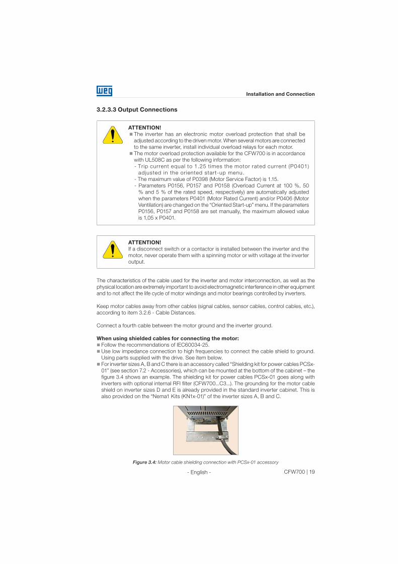
For inverter sizes A, B and C there is an accessory called “Shielding kit for power cables PCSx-
01” (see section 7.2 - Accessories), which can be mounted at the bottom of the cabinet – the
figure 3.4 shows an example. The shielding kit for power cables PCSx-01 goes along with
inverters with optional internal RFI filter (CFW700...C3...). The grounding for the motor cable
shield on inverter sizes D and E is already provided in the standard inverter cabinet. This is
also provided on the “Nema1 Kits (KN1x-01)” of the inverter sizes A, B and C.
Figure 3.4: Motor cable shielding connection with PCSx-01 accessory

20 | CFW700
Installation and Connection
- English -
3.2.4 Grounding Connections
DANGER!
The inverter shall be connected to a Protective Ground (PE).
Use the minimum ground wiring gauge as indicated in the tables B.1 and B.2.
Connect the inverter grounding connections to a ground bus bar, to a single
ground point, or to a common grounding point (impedance ≤ 10 Ω).
The neutral conductor of the network shall be solidly grounded; however,
this conductor shall not be used to ground the inverter.
It is necessary to use a copper cable with 10 mm2 minimum or 2 cables with
the same wire gauge as specified in tables B.1 and B.2 for connecting the
inverter to the ground protection to be in accordance with IEC61800-5-1
since the leakage current is greater than 3.5 mA AC.
3.2.5 Control Connections
The control connections (analog inputs/outputs and digital inputs/outputs), shall be performed
in connector XC1 of the CC700 control board. Functions and typical connections are presented
in figures 3.5 (a), (b) and (c).
GN
D (24
V)
Wh
ite
RE
F+
AI1
+
AI1
-
RE
F-
AO
1
AO
2
AG
ND
(24 V
)
AG
ND
(24 V
)
AI2
+
AI2
-
rpm
am
p
+V A A B B Z Z GN
D
Blu
e
Red
Gre
en
Yello
w
Pin
k
Gre
yZZBBAA+5 V
-EN
C
Bro
wn
B -
RS
48
5
>3
00
Ω
DO
2
DO
3
DO
4
DO
5
+24
V+
24
V
CO
M
GN
D (24
V)
RL1-N
A
RL1-C
RL1-N
F
DI5
DI1
DI6
DI2
DI7
DI3
DI8
DI4
>3
00
Ω
>3
00
Ω
>3
00
Ω
Linedrive encoder or push-pull (1)
A -
RS
48
5
GN
D-E
NC
≥5
kΩ
Active high digital inputs (2)
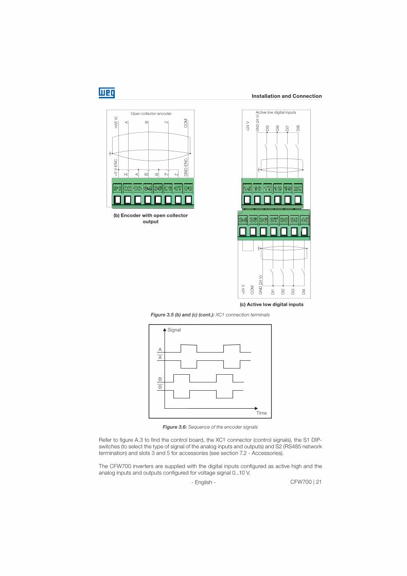
(1) Refer to figure 3.5 (b) for the open-collector encoder connection.
(2) Refer to figure 3.5 (c) for active low digital inputs connection.
(a) Linedrive encoder or push-pull and active high digital inputs
Figure 3.5 (a): XC1 connection terminals
CFW700 | 21
Installation and Connection
- English -
+24
V
GN
D (24 V
)
DI5
DI6
DI7
DI8
Active low digital inputs
+24
V
CO
M
GN
D (24
V)
DI1
DI2
DI3
DI4
(c) Active low digital inputs
Open collector encoder
ZZZ
BBB
AAA
+V
(5 V
)+
5 V
-EN
C
GN
D-E
NC
CO
M
(b) Encoder with open collector
output
Figure 3.5 (b) and (c) (cont.): XC1 connection terminals
Signal
Time
A
B
A
B
Figure 3.6: Sequence of the encoder signals
Refer to figure A.3 to find the control board, the XC1 connector (control signals), the S1 DIP-
switches (to select the type of signal of the analog inputs and outputs) and S2 (RS485 network
termination) and slots 3 and 5 for accessories (see section 7.2 - Accessories).
The CFW700 inverters are supplied with the digital inputs configured as active high and the
analog inputs and outputs configured for voltage signal 0...10 V.

22 | CFW700
Installation and Connection
- English -
NOTE!
To be able to use the analog input and/or output as current signals, it is
necessary to change the switch S1 and the related parameters as per table
3.1. In order to set the analog inputs to bipolar voltage signal (-10…10V), it is
necessary to set P0233 and P0238 according to table 3.1. Refer to the CFW700
Programming and Troubleshooting manual for more information.
Table 3.1: Configuration of the switch for the analog input and output signals selection
Input/
OutputSignal
S1 switch
settings
Signal
rangeParameter settings
AI1
Voltage S1.2 = OFF (*)0…10 V (*) P0233 = 0 (direct reference) or 2 (reverse reference).
-10…10 V P0233 = 4
Current S1.2 = ON 0...20 mA P0233 = 0 (direct reference) or 2 (reverse reference).
4...20 mA P0233 = 1 (direct reference) or 3 (reverse reference).
AI2
Voltage S1.1 = OFF (*)0…10 V (*) P0238 = 0 (direct reference) or 2 (reverse reference).
-10…10 V P0238 = 4
Current S1.1 = ON0...20 mA P0238 = 0 (direct reference) or 2 (reverse reference).
4...20 mA P0238 = 1 (direct reference) or 3 (reverse reference).
AO1
Voltage S1.3 = ON (*) 0...10 V (*) P0253 = 0 (direct reference) or 2 (reverse reference).
Current S1.3 = OFF0...20 mA P0253 = 0 (direct reference) or 2 (reverse reference).
4...20 mA P0253 = 1 (direct reference) or 3 (reverse reference).
AO2
Voltage S1.4 = ON (*) 0...10 V (*) P0256 = 0 (direct reference) or 2 (reverse reference).
Current S1.4 = OFF0...20 mA P0256 = 0 (direct reference) or 2 (reverse reference).
4...20 mA P0256 = 1 (direct reference) or 3 (reverse reference).
(*) Factory setting.
NOTE!
Settings of the S2 switch:
S2.1 = ON and S2.2 = ON: RS485 is ON.
S2.1 = OFF and S2.2 = OFF: RS485 is OFF.
The factory default for the S2.1 and S2.2 switches are OFF.
Other combinations of switch S2 are not allowed.
Technical specifications for the encoder and the encoder cable as shown in table 3.2.
Table 3.2: Technical specifications for the encoder and the encoder cable
Characteristics Specifications
Encoder
Power supply 5 V
Channels2 channels in quadrature (90º) + zero pulses with complementary outputs
(differentials) or open-collector.
SignalsA, A, B, B, Z and Z
Available for 2 channels: A, A, B, B.
Output circuit Linedrive type, push-pull or open-collector. Maximum voltage of 12 V.
Isolation Electronic circuit isolated from the encoder frame.
Pulses Recommended number of pulses per rotation = 1024ppr.
Frequency Maximum allowed = 100 kHz.
Encoder
cable
Type of cable Balanced cable shield (for differential signals operation).
ConnectionThe cable shield must be connected to ground through devices on
control shield plate (see figure 3.5).
Distance ≥ 25 cm of other wiring.
Isolation Use metal conduit.
Length Maximum = 10 m.

CFW700 | 23
Installation and Connection
- English -
Follow instructions below for the proper installation of the control wiring:
1) Wire gauge: 0.5 mm² (20 AWG) to 1.5 mm² (14 AWG).
2) Maximum tightening torque: 0.50 N.m (4.50 lbf.in).
3) Use shielded cables for the connections in XC1 and run the cables separated from the
remaining circuits (power, 110 V / 220 Vac control, etc.), according to item 3.2.6 - Cable
Distances. If control wiring must cross other cables (power cables for instance), make it
cross perpendicular to the wiring and provide a minimum separation of 5 cm (1.9 in) at the
crossing point.
Refer to item 3.2.6 - Cable Distances for the proper cable distances.
Do not ground
Inverter
side
Isolate with tape
(a) Cable shield connection(b) Connection sample of the shield to
ground
Figure 3.7 (a) and (b): Shield connection
4) Relays, contactors, solenoids or coils of electromechanical brakes installed close to the
inverter may eventually create interferences in the control circuitry. To eliminate this effect,
RC suppressors (with AC power supply) or free-wheel diodes (with DC power supply) shall
be connected in parallel to the coils of these devices.
3.2.6 Cable Distances
The power cables and control cables must be separated (relay output cables and other control
cables) according to table 3.3.
Table 3.3: Cable distances
Rated output
inverter currentCable length(s)
Minimum separation
distance
≤ 24 A≤ 100 m (330 ft)
> 100 m (330 ft)
≥ 10 cm (3.94 in)
≥ 25 cm (9.84 in)
≥ 28 A≤ 30 m (100 ft)
> 30 m (100 ft)
≥ 10 cm (3.94 in)
≥ 25 cm (9.84 in)
3.3 INSTALLATION ACCORDING TO THE EUROPEAN DIRECTIVE OF
ELECTROMAGNETIC COMPATIBILITY
The inverters with C3 option (CFW700...C3...) have internal RFI filter to reduce electromagnetic
interference. These inverters, when properly installed, meet the requirements of “EMC Directive
89/336/EEC” with the 93/68/EEC supplement.
The CFW700 inverter series has been designed only for industrial applications. Therefore, the
emission limits of harmonic currents defined by the standards EN 61000-3-2 and EN 61000-
3-2/A 14 are not applicable.

24 | CFW700
Installation and Connection
- English -
3.3.1 Conformal Installation
1) Inverters with built-in RFI filter CFW700...C3...
2) Sizes A to D inverters with built in RFI filter capacitors grounding screws and size E with J1
cable in the position (XE1). For more information see figure A.6.
3) Shielded output cables (motor cables) and connect the shield at both ends (motor and
inverter) with a low impedance connection for high frequency. Use PCSx-01 kit supplied
with sizes A, B and C inverters. For sizes D and E inverters use the clamps supplied with
the product. Ensure good contact between the cable shield and the clamps. Refer to figure
3.4 and keep the proper separation from other cables according to item 3.2.6 - Cable
Distances. The maximum motor cable length and conduction and radiated emission levels
are presented at table B.6. Use an external RFI filter at the input of the inverter if necessary
to have a lower emission level and/or a longer motor cable length. For more information (RFI
filter commercial reference, motor cable length and emission levels) refer to table B.6.
4) Shielded control cables and separate the remaining cables according to item 3.2.6 - Cable
Distances.
5) Inverter grounding according to the instructions on item 3.2.4 - Grounding Connections.
6) Grounded power supply.
3.3.2 Emission and Immunity Levels
Table 3.4: Emission and immunity levels
EMC PhenomenonBasic
StandardLevel
Emission:
Mains Terminal Disturbance Voltage
Frequency Range: 150 kHz to 30 MHz)IEC/EN61800-3
It depends on the inverter model and the motor
cable length.
See table B.6.Electromagnetic Radiation Disturbance
Frequency Range: 30 MHz to 1000 MHz)
Immunity:
Electrostatic Discharge (ESD) IEC 61000-4-24 kV for contact discharge and 8 kV for air
discharge.
Fast Transient-Burst IEC 61000-4-4
2 kV / 5 kHz (coupling capacitor) power input
cables;
1 kV / 5 kHz control cables, and remote
keypad cables;
2 kV / 5 kHz (coupling capacitor) motor output
cables.
Conducted Radio-Frequency Common
ModeIEC 61000-4-6
0.15 to 80 MHz; 10 V; 80 % AM (1 kHz).
Motor cable, control and remote keypad (HMI).
Surge Immunity IEC 61000-4-5
1.2/50 μs, 8/20 μs;
1 kV line-to-line coupling;
2 kV line-to-ground coupling.
Radio-Frequency Electromagnetic Field IEC 61000-4-3
80 to 1000 MHz;
10 V/m;
80 % AM (1 kHz).
Refer to table B.6 for conducted and radiated emission levels accomplished with and without
external RFI filter. The reference model for the external filter is also presented.

CFW700 | 25
Keypad (HMI) and Basic Programming
- English -
4. KEYPAD (HMI) AND BASIC PROGRAMMING
4.1 INTEGRAL KEYPAD - HMI-CFW700
The integral keypad can be used to operate and program (view / edit all parameters) of the
CFW700 inverter. There are two operation modes in the keypad: monitoring and programming.
The key functions and display indications of the keypad may change according to the operation
mode. The programming mode consists of three levels.
- Press this key to accelerate the motor up to the speed set in P0122. The motor speed is maintained
while the key is pressed. When the key is released the motor decelerates up to its complete stop.
This function is active when all the following conditions are met:
1. Start/Stop = Stop;
2. General Enable = Active;
3. P0225 = 1 in LOC and/or P0228 = 1 in REM.
- When in monitoring mode: press this key to
decrease the speed.
- When in programming mode, level 1: press this key
to go to the next group.
- When in programming mode, level 2: press this key
to go back to the previous parameter.
- When in programming mode, level 3: press this key
to decrease the parameter value.
- When in monitoring mode: press this key to enter in
the programming mode.
- When in programming mode, level 1: press this key
to select the desired parameter group – it shows
the parameters of the selected group.
- When in programming mode, level 2: press this key
to show the parameter – it shows the parameter
value for its modification.
- When in programming mode, level 3: press this key
to save the new parameter value – it returns to level
2 of the programming mode.
- Press this key to accelerate the motor according to
the acceleration ramp time.
This option is active when:
P0224 = 0 in LOC and/or
P0227 = 0 in REM.
- Pressione esta tecla para desacelerar o motor com
tempo determinado pela rampa de desaceleração.
Ativa quando:
P0224 = 0 em LOC e/ou
P0227 = 0 em REM.
- When in monitoring mode: press this key to increase the
speed.
- When in programming mode, level 1: press this key to go
back to the previous group.
- When in programming mode, level 2: press this key to go
to the next parameter.
- When in programming mode, level 3: press this key to
increase the parameter value.
- When in programming mode,
level 1: press this key to go
back to the monitoring mode.
- When in programming mode,
level 2: press this key to go
back to the level 1.
- When in programming mode,
level 3: press this key to
cancel the new value (the
value will not be saved) and
it will return to level 2 of the
programming mode.
- Press this key to define the
motor rotation.
This option is active when:
P0223 = 2 or 3 in LOC and/
or
P0226 = 2 or 3 in REM.
- Press this key to change
between LOCAL and
REMOTE mode.
This option is active when:
P0220 = 2 or 3.
Figure 4.1: Operator keys
NOTE!
It is necessary to set the password at P0000 for parameter modification;
otherwise the parameters contents can only be viewed.
The default password for P0000 is 5. It is possible to change the password
at P0200. Refer to the CFW700 Programming and Troubleshooting manual.

26 | CFW700
Keypad (HMI) and Basic Programming
- English -
Inverter
statusLocal/Remote ()
Secondary display
Variable unit
(shows the value of
the main display)
Variable monitoring
bar graph
Menu (parameters
group selection) –
only one parameter
group is shown at
each time.
Main display
Motor rotation
Figure 4.2: Display sections
Parameter groups available at the Menu:
PARAM: all parameters;
READ: only the reading parameters;
MODIF: only the parameters changed compared to the factory default;
BASIC: basic application parameters;
MOTOR: parameters related to motor data control;
I/O: parameters related to the digital and analog inputs/outputs;
NET: parameters related to the communication protocol;
HMI: parameters for the keypad configuration;
SPLC: parameters related to the SoftPLC function;
STARTUP: parameters for the oriented startup.
Inverter status:
LOC: local reference;
REM: remote reference;
: motor rotation according to the arrows;
CONF: configuration;
SUB: DC link undervoltage;
RUN: inverter enabled and/or DC braking activated.
CFW700 | 27
Keypad (HMI) and Basic Programming
- English -
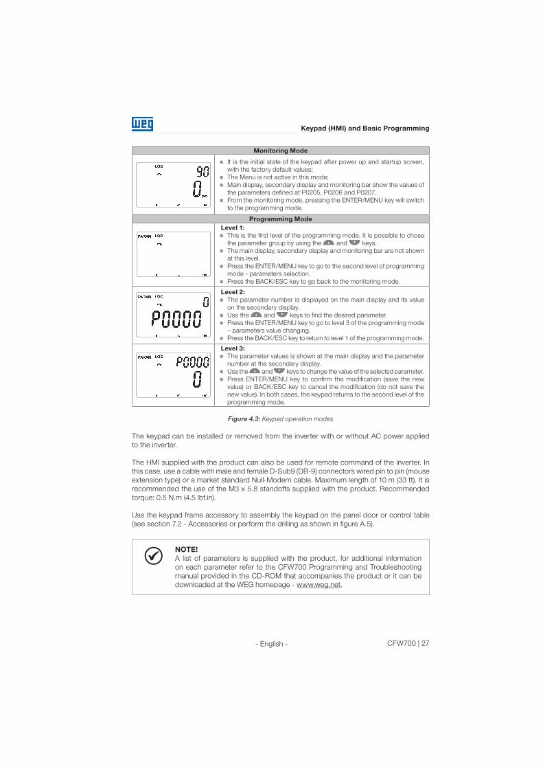
Monitoring Mode
It is the initial state of the keypad after power up and startup screen,
with the factory default values;
The Menu is not active in this mode;
Main display, secondary display and monitoring bar show the values of
the parameters defined at P0205, P0206 and P0207.
From the monitoring mode, pressing the ENTER/MENU key will switch
to the programming mode.
Programming Mode
Level 1:
This is the first level of the programming mode. It is possible to chose
the parameter group by using the and keys.
The main display, secondary display and monitoring bar are not shown
at this level.
Press the ENTER/MENU key to go to the second level of programming
mode - parameters selection.
Press the BACK/ESC key to go back to the monitoring mode.
Level 2:
The parameter number is displayed on the main display and its value
on the secondary display.
Use the and keys to find the desired parameter.
Press the ENTER/MENU key to go to level 3 of the programming mode
– parameters value changing.
Press the BACK/ESC key to return to level 1 of the programming mode.
Level 3:
The parameter values is shown at the main display and the parameter
number at the secondary display.
Use the and keys to change the value of the selected parameter.
Press ENTER/MENU key to confirm the modification (save the new
value) or BACK/ESC key to cancel the modification (do not save the
new value). In both cases, the keypad returns to the second level of the
programming mode.
Figure 4.3: Keypad operation modes
The keypad can be installed or removed from the inverter with or without AC power applied
to the inverter.
The HMI supplied with the product can also be used for remote command of the inverter. In
this case, use a cable with male and female D-Sub9 (DB-9) connectors wired pin to pin (mouse
extension type) or a market standard Null-Modem cable. Maximum length of 10 m (33 ft). It is
recommended the use of the M3 x 5.8 standoffs supplied with the product. Recommended
torque: 0.5 N.m (4.5 lbf.in).
Use the keypad frame accessory to assembly the keypad on the panel door or control table
(see section 7.2 - Accessories or perform the drilling as shown in figure A.5).
NOTE!
A list of parameters is supplied with the product, for additional information
on each parameter refer to the CFW700 Programming and Troubleshooting
manual provided in the CD-ROM that accompanies the product or it can be
downloaded at the WEG homepage - www.weg.net.

28 | CFW700
Keypad (HMI) and Basic Programming
- English -
4.2 APPLICATIONS
The CFW700 has some features that allow better matching the inverter commands to the
application. These features were grouped into a set of applications and can be as simple as the
forward and reverse command, or more elaborated such as a PID controller.The applications
were implemented using the SoftPLC function, in other words, ladder programming applicative
built-in to the CFW700 inverter. It allows the user that has the WLP and the built-in implemented
applicative to change it and use it as an user applicative.
Parameter P1003 allows selecting an application and uploading it to the CFW700. The CFW700
has following applications built-in:
PID Regulator;
Electronic Potentiometer (E.P.);
Multispeed;
3-Wire Start/Stop;
Forward/Reverse Run.
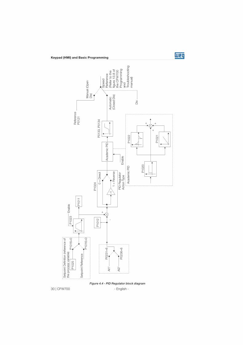
4.2.1 PID Regulator Application
The CFW700 has the PID REGULATOR application that can be used to control a closed loop
process. This application sets proportional, integral and derivative regulator superimposed to
the regular speed control of the CFW700 inverter.
The CFW700 will compare the setpoint with the process variable and control the motor speed
trying to eliminate any error and keeping the process variable equal to the setpoint. The setting
of the P, I and D gains determines how fast the inverter will respond to eliminate this error.
Application examples:
Flow control or pressure in a pipe system;
Temperature of a furnace or oven;
Dosing of chemicals in tanks.
The following example defines the terms used by the PID controller.
A pump used in a water pumping system where is necessary to control the pressure of the
pipe. A pressure transducer is installed in the pipe and supplies an analog feedback signal
to the CFW700, which is proportional to the water pressure. This signal is called the process
variable, and can be visualized at the parameter P1012. A setpoint is programmed in the
CFW700 via keypad (P1025), through an analog input (such as a 0-10 V or 4-20 mA signal) or
via communication network. The setpoint is the desired water pressure value that the pump is
supposed to produce, regardless of the consumption variations at the pump output at any time.
It is necessary to set the parameter P0221 or P0222 to 7=SoftPLC for the operation of the PID
Regulator application.
Definitions:
The Function 1 of the Application at parameters P0231 or P0236 represents the value of the
PID Setpoint;
The Function 2 of the Application at parameters P0231 or P0236 represents the value of the
PID Feedback;
The Function 1 of the Application at parameters P0251 or P0254 represents the value of the
PID Setpoint;

CFW700 | 29
Keypad (HMI) and Basic Programming
- English -
The Function 2 of the Application at parameters P0251 or P0254 represents the value of the
PID Feedback;
The Function 1 of the Application at parameters P0263 or P0270 represents the value of the
Manual/Auto command;
The Function 1 of the Application at parameters P0275 to P0279 represents the VP>VPx
logical condition;
The Function 2 of the Application at parameters P0275 to P0279 represents the VP<VPy
logical condition.
The PID setpoint can receive an analog input signal (AI1 or AI2). It is necessary to set P1016
to 1=AIx and select which analog input will be used. The analog inputs are set at P0231 (AI1)
or P0236 (AI2) and it is necessary to program it to 5=Function 1 of the Application in order to
enable the analog inputs for the operation. The following alarm message will be displayed in
case it is not properly done: “A770: Set AI1 or AI2 for Function 1 of the Application”.
The PID setpoint value can be presented via analog output AO1 or AO2. It is necessary to
set P0251 (AO1) or P0254 (AO2) to 17 = Function 1 of the Application. The full scale value of
the variable is 100.0 % and corresponds to 10 V or 20 mA.
The PID feedback can receive an analog input signal (AI1 or AI2). It is necessary to set P0231
(AI1) or P0236 (AI2) to 6 = Function 2 of the Application in order to enable the analog inputs for
the operation. The following alarm message will be displayed in case it is not properly done:
“A772: Set AI1 or AI2 for Function 2 of the Application”.
In case the analog inputs (AI1 and AI2) are programmed with the same function, PID Setpoint
or Feedback, the following alarm message will be displayed and the application will not be
enabled: “A774: AI1 and AI2 were set for the same function”.
The value of the PID feedback can be presented via analog output AO1 or AO2. It is necessary
to set P0251 (AO1) or P0254 (AO2) to 18 = Function 2 of the Application. The full scale value of
the variable is 100.0 % and corresponds to 10 V or 20 mA.
The Manual/Auto control is done by a digital input (DI1 to DI8). It is necessary to set one of the
DI parameters (P0263 to P0270) to 20 = Function 1 of the Application. If more than one digital
input is set for this function, the logic operation will consider only the command of the high
priority level digital input, where: DI1>DI2>DI3>DI4>DI5>DI6>DI7> DI8. If any of the digital inputs
is set, the PID controller will work only in automatic (Auto) mode.
The Manual/Auto input is active when it is in 24 V indicating automatic control and it is inactive
in 0 V indicating manual operation.
The digital outputs (DO1 to DO5) can be programmed to trigger comparison logics with the
process variable (PV). In order to do that, it is necessary to set one of the DO’s parameters
(P0275 to P0279) to 34 = Function 1 of the Application (VP>VPx) or 35 = Function 2 of the
Application (VP<VPy).
30 | CFW700
Keypad (HMI) and Basic Programming
- English -
Setp
oin
t D
efin
itio
n (re
fere
nce o
f
the p
rocess v
ariab
le)
P1025
Setp
oin
t R
efe
rence
P1016=
0
Enab
le
P1011
+
-A
cad
em
ic P
ID
P0133, P
0134
P1024
-1
0 =
Direct
1 =
Revers
e
PID
Regula
tor
Action T
yp
e
Manual (O
pen
DIx
)
DIx
Acad
em
ic P
IDP
1022
P1021
+ ++
Sp
eed
Refe
rence
(Refe
r to
the
fig
ure
13
.8 o
f
the C
FW
70
0
Pro
gra
mm
ing
and
Tro
ub
leshooting
manual)
P1020
Enab
le
Refe
rence
P0121
P1023
P1016>
0
P0231=
6
P1012
P0236=
6A
I2'
AI1
'A
uto
matic
(Clo
sed
DIx
)
Figure 4.4 - PID Regulator block diagram

CFW700 | 31
Keypad (HMI) and Basic Programming
- English -
4.2.1.1 Academic PID
The PID controller implemented in CFW700 is the academic type. The equations that characterize
the Academic PID, which is the base of this function algorithm, are presented next.The transfer
function in the Academic PID regulator frequency dominion is:
y(s) = Kp x e(s) x [1 + 1 + sTd]
sTi
By replacing the integrator by a sum and the derivative by the incremental quotient, one gets
an approximation for the discrete transfer equation (recursive) presented next:
y(k) = y(k-1) + Kp[(1 + Ki.Ta + Kd/Ta).e(k) – (Kd/Ta).e(k-1)]
Being:
y(k): current PID output, can vary from 0.0 to 100.0 %;
y(k-1): PID previous output;
Kp (Proportional gain): Kp = P1020;
Ki (Integral gain): Ki = P1021 x 100 = [1/Ti x 100];
Kd (Differential gain): Kd = P1022 x 100 = [Td x 100];
Ta = 0.05sec (PID regulator sampling time);
e(k): current error [SP*(k) – X(k)];
e(k-1): previous error [SP*(k-1) – X(k-1)];
SP*: reference, can vary from 0.0 to 100.0 %;
X: process variable (or feedback), read through one of the analog inputs (AIx), can vary from
0.0 to 100.0 %.
P1010 – Version of the PID Regulator Application
Adjustable
Range:
0.00 to 10.00 Factory
Setting:
-
Properties: ro
Access groups
via HMI:
SPLC
Description:
Read only parameter that presents the software version of the PID regulator application
developed for the SoftPLC function of the CFW700.
P1011 – PID Setpoint
Adjustable
Range:
0.0 to 3000.0 Factory
Setting:
-
Properties: ro
Access groups
via HMI:
SPLC
Description:
Read only parameter that presents, in the wxy.z form without engineering unit, the setpoint
value of the PID regulator according to the scale defined at P1018.

32 | CFW700
Keypad (HMI) and Basic Programming
- English -
P1012 – PID Feedback
Adjustable
Range:
0.0 to 3000.0 Factory
Setting:
-
Properties: ro
Access groups
via HMI:
SPLC
Description:
Read only parameter that presents, in the wxy.z form without engineering unit, the setpoint
value or the process variable of the PID regulator according to the scale defined at P1018.
P1013 – PID Output
Adjustable
Range:
0.0 to 100.0 % Factory
Setting:
-
Properties: ro
Access groups
via HMI:
SPLC
Description:
Read only parameter that presents, in percentage (%), the PID regulator output value.
P1016 – PID Setpoint Selection
Adjustable
Range:
0 = HMI
1 = AIx
2 = Serial/USB
3 = CO/DN/DP
Factory
Setting:
0
Properties: ro
Access groups
via HMI:
SPLC
Description:
Defines the source of the PID regulator setpoint.
Notes:
“HMI” means that the PID regulator setpoint will be the value of P1025 parameter.
“AI” means that the PID regulator setpoint will come from an analog input. It is necessary
to set P0231 (AI1) or P0236 (AI2) to 5 = Function 1 of the Application in order to enable its
operation. The following alarm message will be displayed in case it is not properly done:
“A770: Set AI1 or AI2 for Function 1 of the Application”.
“Serial/USB” means that the setpoint of the PID will be the value of P0683 proportionally
referenced to the percentage value with one decimal point, i.e., 100.0 % corresponds to
1000 in P0683.
“CO/DN/DP” means that the setpoint of the PID regulator will be the value of P0685
proportionally referenced to the percentage value with one decimal point, i.e., 100.0 %
corresponds to 1000 in P0685.

CFW700 | 33
Keypad (HMI) and Basic Programming
- English -
P1018 – PID Feedback Scale
Adjustable
Range:
0.0 to 3000.0 Factory
Setting:
100.0
Properties: -
Access groups
via HMI:
SPLC
Description:
Defines how the PID Feedback or Process Variable will be presented in P1012 (as well as
the PID setpoint in P1011), i.e., the full scale of the PID feedback or process variable that
corresponds to 100.0 % in the analog input used as the PID regulator feedback.
The variable will always be with one decimal point “wxy.z”, i.e., one place after the dot.
Example: The pressure transducer is a 4-20 mA with 0-25 bar range. Set P1019 to 25.0.
P1020 – PID Proportional Gain
P1021 – PID Integral Gain
P1022 – PID Differential Gain
Adjustable
Range:
0.000 to 30.000 Factory
Setting:
P1020 = 1.000
P1021 = 0.430
P1022 = 0.000
Properties: -
Access groups
via HMI:
SPLC
Description:
These parameters define the PID regulator application gains and they should be set according
to the application being controlled.
Examples of initial settings for some applications are presented in table 4.1.
Table 4.1 : Recommended settings for the PID regulator gains
Variable
Gains
Proportional
P1020
Integral
P1021
Derivative
P1022
Pneumatic system Pressure 1 0.430 0.000
Pneumatic system flow 1 0.370 0.000
Hydraulic system Pressure 1 0.430 0.000
Hydraulic system flow 1 0.370 0.000
Temperature 2 0.040 0.000
Level 1 - See note bellow 1 See note below 0.000
34 | CFW700
Keypad (HMI) and Basic Programming
- English -
NOTE!
For the level control, the integral gain settings will depend on the time it takes
for the reservoir to go through the minimum acceptable level to the desired
level, with the following conditions:
1. The time for the direct action should be measured with the maximum input
flow and minimum output flow.
2. The time for the reverse action should be measured with minimum input
flow and maximum output flow.
An equation to calculate the initial value of P1021 as a function of the system response time
is presented next:
P1021=5.00 / t,
Where: t=time (in seconds)
P1023 – PID Setpoint Filter
Adjustable
Range:
0.00 to 650.00 s Factory
Setting:
3.0 s
Properties: -
Access groups
via HMI:
SPLC
Description:
This parameter sets the value of the constant time of the setpoint filter of the PID regulator
and has the purpose of reducing abrupt changes in the PID setpoint value.
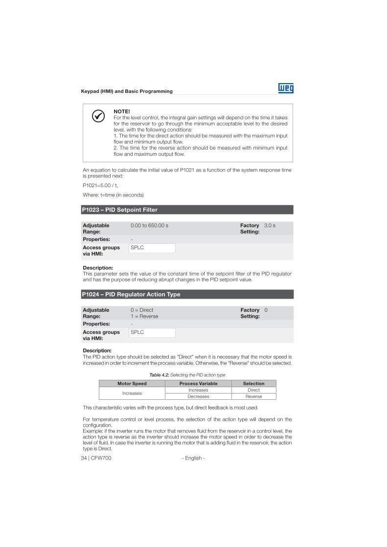
P1024 – PID Regulator Action Type
Adjustable
Range:
0 = Direct
1 = Reverse
Factory
Setting:
0
Properties: -
Access groups
via HMI:
SPLC
Description:
The PID action type should be selected as "Direct" when it is necessary that the motor speed is
increased in order to increment the process variable. Otherwise, the "Reverse" should be selected.
Table 4.2: Selecting the PID action type
Motor Speed Process Variable Selection
IncreasesIncreases Direct
Decreases Reverse
This characteristic varies with the process type, but direct feedback is most used.
For temperature control or level process, the selection of the action type will depend on the
configuration.
Example: if the inverter runs the motor that removes fluid from the reservoir in a control level, the
action type is reverse as the inverter should increase the motor speed in order to decrease the
level of fluid. In case the inverter is running the motor that is adding fluid in the reservoir, the action
type is Direct.

CFW700 | 35
Keypad (HMI) and Basic Programming
- English -
P1025 – PID Setpoint via Keypad Keys (HMI)
Adjustable
Range:
0.0 to 100.0 % Factory
Setting:
0.0 %
Properties: -
Access groups
via HMI:
SPLC
Description:
This parameter allows the adjustment of the PID regulator setpoint through the keypad keys,
since P1016 = 0 and it is operating in Auto mode. If the operation is in Manual mode, the
keypad reference is set in P0121.
The value of P1025 is kept with the last value set (backup) even after disabling or resetting
the inverter (with P1027 = 1 - Active).
P1026 – Automatic Setting of the PID Setpoint via Keypad (P1025)
Adjustable
Range:
0 = Inactive
1 = Active
Factory
Setting:
1
Properties: cfg
Access groups
via HMI:
SPLC
Description:
When the PID regulator setpoint is done via the keypad (P1016 = 0) and P1026 is 1 (active),
when switching from manual to automatic, the percentage value of the manual setpoint that
corresponds to the PID regulator output from 0.0 to 100.0 % will be loaded at P1025. It avoids
PID oscillations when switching from manual to automatic.
P1027 – PID Setpoint Backup via Keypad (P1025)
Adjustable
Range:
0 = Inactive
1 = Active
Factory
Setting:
1
Properties: -
Access groups
via HMI:
SPLC
Description:
This parameter sets whether the backup function of the PID setpoint via keypad is active or
inactive.
If P1027 = 0 (Inactive), the inverter will not save the value of the PID setpoint when disabled.
Therefore, when the inverter is enabled again, the PID setpoint value is 0.0 %.
36 | CFW700
Keypad (HMI) and Basic Programming
- English -
P1028 – PID Output N = 0
Adjustable
Range:
0.0 to 100.0 % Factory
Setting:
0.0 %
Properties: -
Access groups
via HMI:
SPLC
Description:
The parameter P1028 works together with the parameter P0218 (Condition to Leave the
Zero Speed Disable), providing additional requirement to leave the disable condition. Thus,
it is necessary that the error of the PID (the difference between the setpoint and process
variable) is greater than the value programmed in P1028 for the inverter to operate the motor
again, this state is known as “wake up”.
P1031 – X Process Variable Value
P1032 – Y Process Variable Value
Adjustable
Range:
0.0 to 100.0 % Factory
Setting:
P1031 = 90.0 %
P1032 = 10.0 %
Properties: -
Access groups
via HMI:
SPLC
Description:
These parameters are used at the digital outputs functions for signaling/alarm, and will show:
Process Variable > VPx (Function 1 of the Application) and
Process Variable < VPy (Function 2 of the Application).
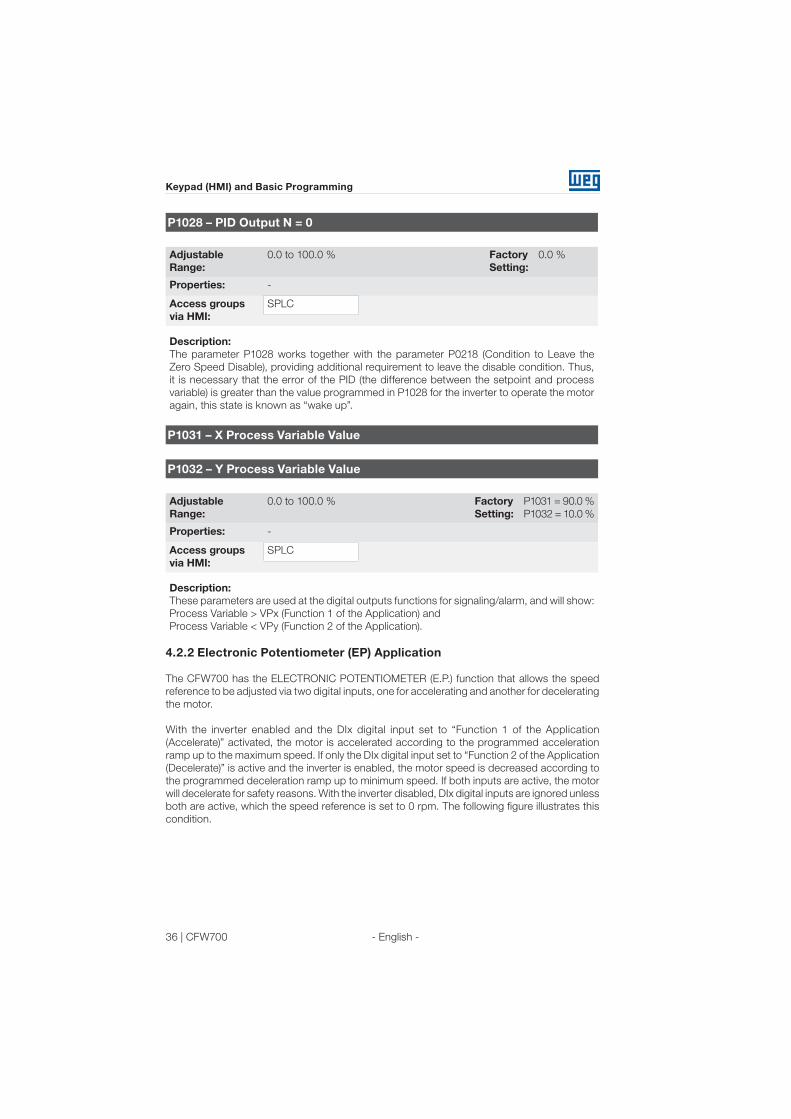
4.2.2 Electronic Potentiometer (EP) Application
The CFW700 has the ELECTRONIC POTENTIOMETER (E.P.) function that allows the speed
reference to be adjusted via two digital inputs, one for accelerating and another for decelerating
the motor.
With the inverter enabled and the DIx digital input set to “Function 1 of the Application
(Accelerate)” activated, the motor is accelerated according to the programmed acceleration
ramp up to the maximum speed. If only the DIx digital input set to “Function 2 of the Application
(Decelerate)” is active and the inverter is enabled, the motor speed is decreased according to
the programmed deceleration ramp up to minimum speed. If both inputs are active, the motor
will decelerate for safety reasons. With the inverter disabled, DIx digital inputs are ignored unless
both are active, which the speed reference is set to 0 rpm. The following figure illustrates this
condition.

CFW700 | 37
Keypad (HMI) and Basic Programming
- English -
Time
Output
Speed
24 V
open
24 V
DIx - Run/Stop
Aceleration
Deceleration
Speed
Reference
Reset
Decrease
&
Increase
Enabling
Minimum
speed
Reset
Digital
Inputs
DIx Decrease
DIx Increase
24 V
openTime
Time
Time
Figure 4.5: Operation of the Electronic Potentiometer Application (E.P.)
It is necessary to set P0221 or P0222 to 7 = SoftPLC for the operation of the electronic
potentiometer application.
Definitions:
The Function 1 of the Application at P0263 to P0270 represents the Accelerate command;
The Function 2 of the Application at P0263 to P0270 represents the Decelerate command;
The accelerate command is done by one of the digital inputs (DI1 to DI8). It is necessary to set
one of the DI’s parameters (P0263 to P0270) to 20 = Function 1 of the Application.
The decelerate command is also done by one of digital inputs (DI1 to DI8). However, it is necessary
to set one the DI’s parameters (P0263 to P0270) to 21 = Function 2 of the Application.
The Accelerate input is active when 24 V is applied and inactive when 0 V is applied. Otherwise,
the Decelerate input is active when 0 V is applied and inactive when 24 V is applied.
The parameters related to this application are:

38 | CFW700
Keypad (HMI) and Basic Programming
- English -
P1010 – Version of the Electronic Potentiometer Application (E.P.)
Adjustable
Range:
0.00 to 10.00 Factory
Setting:
-
Properties: ro
Access groups
via HMI:
SPLC
Description:
Read only parameter that presents the software version of the electronic potentiometer
application developed for the SoftPLC function of the CFW700.
P1011 – E.P. Speed Reference
Adjustable
Range:
0 to 18000 rpm Factory
Setting:
-
Properties: ro
Access groups
via HMI:
SPLC
Description:
Read only parameter that presents, in rpm, the current speed reference value of the electronic
potentiometer application.
P1012 – E.P. Speed Reference Backup
Adjustable
Range:
0 = Inactive
1 = Active
Factory
Setting:
1
Properties: -
Access groups
via HMI:
SPLC
Description:
This parameter sets whether the backup function of the electronic potentiometer speed
reference is active or inactive.
If P1012 = 0 (Inactive), the inverter will not save the value of the speed reference when
disabled. Therefore, when the inverter is enabled again, the speed reference value will be the
minimum speed set in P0133.
CFW700 | 39
Keypad (HMI) and Basic Programming
- English -
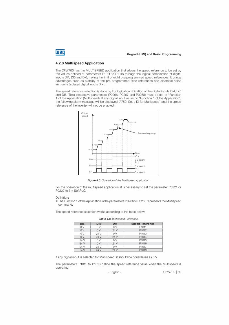
4.2.3 Multispeed Application
The CFW700 has the MULTISPEED application that allows the speed reference to be set by
the values defined at parameters P1011 to P1018 through the logical combination of digital
inputs DI4, DI5 and DI6, having the limit of eight pre-programmed speed references. It brings
advantages such as stability of the pre-programmed fixed references and electrical noise
immunity (isolated digital inputs DIX).
The speed reference selection is done by the logical combination of the digital inputs DI4, DI5
and DI6. Their respective parameters (P0266, P0267 and P0268) must be set to "Function
1 of the Application (Multispeed). If any digital input us set to “Function 1 of the Application”,
the following alarm message will be displayed “A750: Set a DI for Multispeed” and the speed
reference of the inverter will not be enabled.
Output
speed
Accelerating ramp
Time
0 V (open)
0 V (open)
0 V (open)
24 V
24 V
24 V
DI5
DI4
DI6
P1011
P1013
P1014
P1015
P1016
P1017
P1018
P1012
Figure 4.6: Operation of the Multispeed Application
For the operation of the multispeed application, it is necessary to set the parameter P0221 or
P0222 to 7 = SoftPLC.
Definition:
The Function 1 of the Application in the parameters P0266 to P0268 represents the Multispeed
command.
The speed reference selection works according to the table below:
Table 4.1: Multispeed Reference
DI6 DI5 DI4 Speed Reference
0 V 0 V 0 V P1011
0 V 0 V 24 V P1012
0 V 24 V 0 V P1013
0 V 24 V 24 V P1014
24 V 0 V 0 V P1015
24 V 0 V 24 V P1016
24 V 24 V 0 V P1017
24 V 24 V 24 V P1018
If any digital input is selected for Multispeed, it should be considered as 0 V.
The parameters P1011 to P1018 define the speed reference value when the Multispeed is
operating.

40 | CFW700
Keypad (HMI) and Basic Programming
- English -
The parameters related to this application are:
P1010 – Version of the Multispeed Application
Adjustable
Range:
0.00 to 10.00 Factory
Setting:
-
Properties: ro
Access groups
via HMI:
SPLC
Description:
Read only parameter that presents the software version of the multispeed application
developed for the SoftPLC function of the CFW700.
P1011 – Multispeed Reference 1
Adjustable
Range:
0 to 18000 rpm Factory
Setting:
90 rpm
Properties: ro
Access groups
via HMI:
SPLC
Description:
Sets the speed reference 1 for the multispeed application.
P1012 – Multispeed Reference 2
Adjustable
Range:
0 to 18000 rpm Factory
Setting:
300 rpm
Properties: -
Access groups
via HMI:
SPLC
Description:
Sets the speed reference 2 for the multispeed application.
P1013 – Multispeed Reference 3
Adjustable
Range:
0 to 18000 rpm Factory
Setting:
600 rpm
Properties: -
Access groups
via HMI:
SPLC
Description:
Sets the speed reference 3 for the multispeed application.
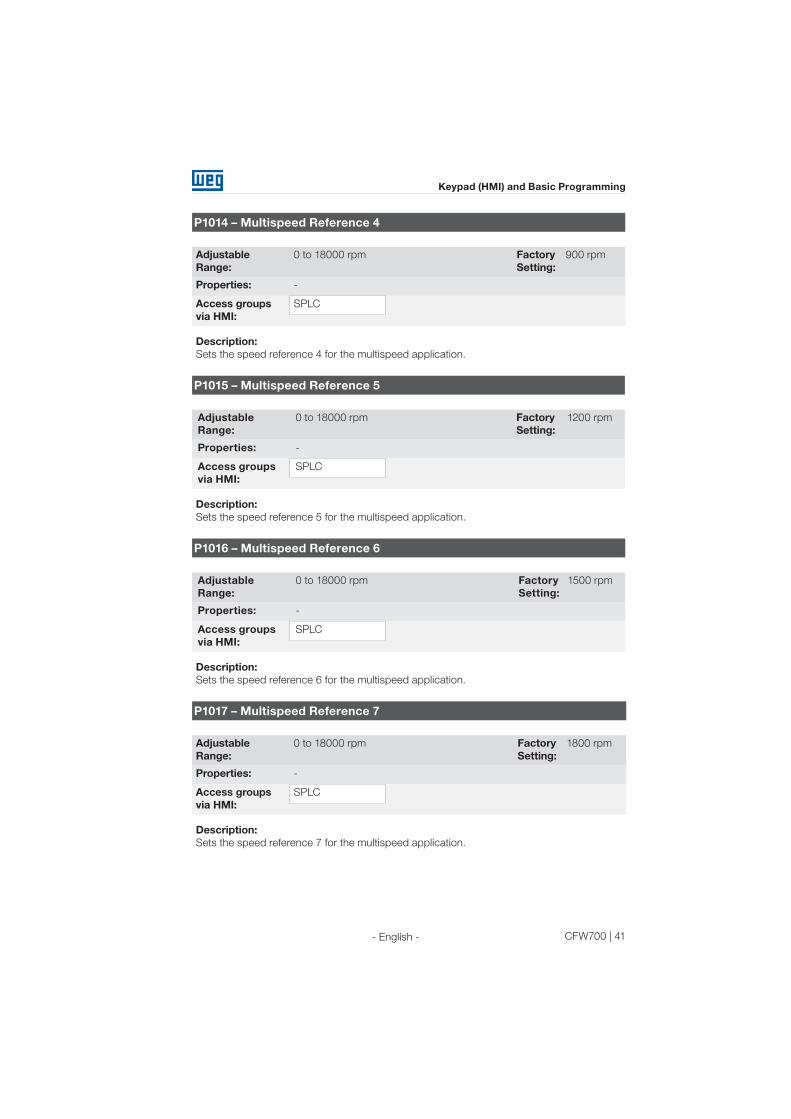
CFW700 | 41
Keypad (HMI) and Basic Programming
- English -
P1014 – Multispeed Reference 4
Adjustable
Range:
0 to 18000 rpm Factory
Setting:
900 rpm
Properties: -
Access groups
via HMI:
SPLC
Description:
Sets the speed reference 4 for the multispeed application.
P1015 – Multispeed Reference 5
Adjustable
Range:
0 to 18000 rpm Factory
Setting:
1200 rpm
Properties: -
Access groups
via HMI:
SPLC
Description:
Sets the speed reference 5 for the multispeed application.
P1016 – Multispeed Reference 6
Adjustable
Range:
0 to 18000 rpm Factory
Setting:
1500 rpm
Properties: -
Access groups
via HMI:
SPLC
Description:
Sets the speed reference 6 for the multispeed application.
P1017 – Multispeed Reference 7
Adjustable
Range:
0 to 18000 rpm Factory
Setting:
1800 rpm
Properties: -
Access groups
via HMI:
SPLC
Description:
Sets the speed reference 7 for the multispeed application.
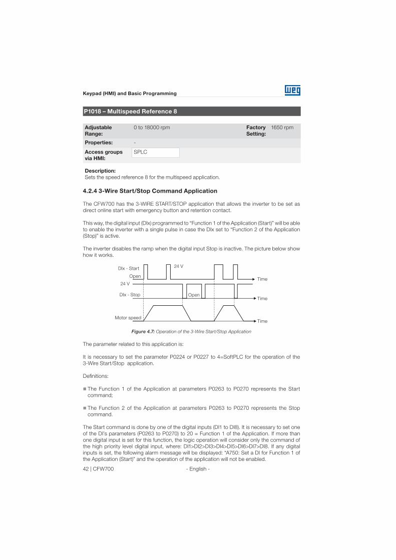
42 | CFW700
Keypad (HMI) and Basic Programming
- English -
P1018 – Multispeed Reference 8
Adjustable
Range:
0 to 18000 rpm Factory
Setting:
1650 rpm
Properties: -
Access groups
via HMI:
SPLC
Description:
Sets the speed reference 8 for the multispeed application.
4.2.4 3-Wire Start/Stop Command Application
The CFW700 has the 3-WIRE START/STOP application that allows the inverter to be set as
direct online start with emergency button and retention contact.
This way, the digital input (DIx) programmed to “Function 1 of the Application (Start)” will be able
to enable the inverter with a single pulse in case the DIx set to “Function 2 of the Application
(Stop)” is active.
The inverter disables the ramp when the digital input Stop is inactive. The picture below show
how it works.
Time
Time
24 V
Motor speed
24 V
Open
OpenDIx - Stop
DIx - Start
Time
Figure 4.7: Operation of the 3-Wire Start/Stop Application
The parameter related to this application is:
It is necessary to set the parameter P0224 or P0227 to 4=SoftPLC for the operation of the
3-Wire Start/Stop application.
Definitions:
The Function 1 of the Application at parameters P0263 to P0270 represents the Start
command;
The Function 2 of the Application at parameters P0263 to P0270 represents the Stop
command.
The Start command is done by one of the digital inputs (DI1 to DI8). It is necessary to set one
of the DI’s parameters (P0263 to P0270) to 20 = Function 1 of the Application. If more than
one digital input is set for this function, the logic operation will consider only the command of
the high priority level digital input, where: DI1>DI2>DI3>DI4>DI5>DI6>DI7>DI8. If any digital
inputs is set, the following alarm message will be displayed: “A750: Set a DI for Function 1 of
the Application (Start)” and the operation of the application will not be enabled.

CFW700 | 43
Keypad (HMI) and Basic Programming
- English -
The Stop command is also done by one of digital inputs (DI1 to DI8). However, it is necessary
to set one the DI’s parameters (P0263 to P0270) to 21 = Function 2 of the Application. If more
than one digital input is set for this function, the logic operation will consider only the command
of the high priority level digital input, where: DI1>DI2>DI3>DI4>DI5>DI6>DI7>DI8. If any digital
inputs is set, the following alarm message will be displayed: “A752: Set a DI for Function 2 of
the Application (Stop)” and the operation of the application will not be enabled.
Both Start and Stop inputs are active when 24 V is applied and inactive when 0 V is applied.
With the inverter enabled in local or remote mode, with no fault, without undervoltage, no A750 and
A752 alarm, the “General Enable” command is performed in the inverter. In case some digital input
is set to “General Enable” function, the inverter will effectively be enabled when the two command
sources are active.
P1010 – Version of the 3-Wire Start/Stop Application
Adjustable
Range:
0.00 to 10.00 Factory
Setting:
-
Properties: ro
Access groups
via HMI:
SPLC
Description:
Read only parameter that presents the software version of the 3-Wire Start/Stop application
developed for the SoftPLC function of the CFW700.
4.2.5 Forward/Reverse Run Application
The CFW700 has the FORWARD/REVERSE RUN application that allows the combination of
two inverter commands (Forward/Reverse and Start/Stop) in a single digital input.
This way, the digital input (DIx) programmed to “Function 1 of the Application (Forward)” combines
the forward rotation with the start/stop command and the input (DIx) programmed to “Function
2 of the Application (Reverse)” combines the reverse rotation with the start/stop command. The
picture below show how it works.
Open
Time
24 V
Time
Time
24 V
OpenDIx - Reverse
DIx - Forward
Motor speedForward
Reverse
Figure 4.8: Operation of the Forward/Reverse Run Application

44 | CFW700
First Time Power-Up and Start-Up
- English -
It is necessary to set the parameter P0223 to 9 = SoftPLC (CW) or 10 = SoftPLC (CCW) together
with P0224 to 4 = SoftPLC, or else, it is necessary to set P0226 to 9 = SoftPLC (CW) or 10 =
SoftPLC (CCW) together with P0227 to 4 = SoftPLC for the operation of the Forward/Reverse Run
application. The following alarm message will be displayed in case the Local FWD/REV selection
is not set (P0223): “A760: Set Local FWD/REV to SoftPLC” and the operation of the application
will not be enabled if the Local Run/Stop selection (P0224) has been set to SoftPLC. The same
applies to the Remote FWD/REV (P0226), i.e., the following alarm message will be displayed:
“A762: Set Remote FWD/REV to SoftPLC” and the operation of the application will not be enabled
if the Remote Run/Stop selection (P0227) has been set to SoftPLC.
Definitions:
The Function 1 of the Application at parameters P0263 to P0270 represents the Forward
command;
The Function 2 of the Application at parameters P0263 to P0270 represents the Reverse
command;
The Forward command is done by one of the digital inputs (DI1 to DI8). It is necessary to set
one of the DI’s parameters (P0263 to P0270) to 20 = Function 1 of the Application. If more than
one digital input is set for this function, the logic operation will consider only the command of
the high priority level digital input, where: DI1>DI2>DI3>DI4>DI5>DI6>DI7>DI8. If any digital
inputs is set, the following alarm message will be displayed: "A750: Set a DI for Function 1 of
the Application (Forward)" and the operation of the application will not be enabled. It is defined
that the forward command rotation will always be “clockwise”.
The Reverse command is also done by one of digital inputs (DI1 to DI8). However, it is necessary
to set one the DI’s parameters (P0263 to P0270) to 21 = Function 2 of the Application. If more
than one digital input is set for this function, the logic operation will consider only the command
of the high priority level digital input, where: DI1>DI2>DI3>DI4>DI5>DI6>DI7>DI8. If any digital
inputs is set, the following alarm message will be displayed: "A752: Set a DI for Function 2 of
the Application (Reverse)" and the operation of the application will not be enabled. It is defined
that the forward command rotation will always be “counterclockwise”.
Both Forward and Reverse inputs are active when 24 V is applied and inactive when 0 V is applied.
With the inverter enabled in local or remote mode, with no fault, without undervoltage, no A750,
A752, A760 and A1762 alarms, the "General Enable" command is performed in the inverter. In
case some digital input is set to "General Enable" function, the inverter will effectively be enabled
when the two command sources are active.
With the forward digital input active and the reverse digital input inactive, the forward and
start commands are performed. If the reverse digital input is active, nothing is changed in the
operation of the inverter. When both commands are inactive, the start command is removed
and the motor will be decelerated to 0 rpm. However, when the reverse digital input is active
and the forward digital input is inactive, the reverse and start command are performed. If the
forward digital input is active, nothing is changed in the operation of the inverter. When both
commands are inactive, the start command is removed and the inverter decelerates to 0
rpm. In case both forward and reverse digital inputs are active at the same time, the forward
command will be generated.
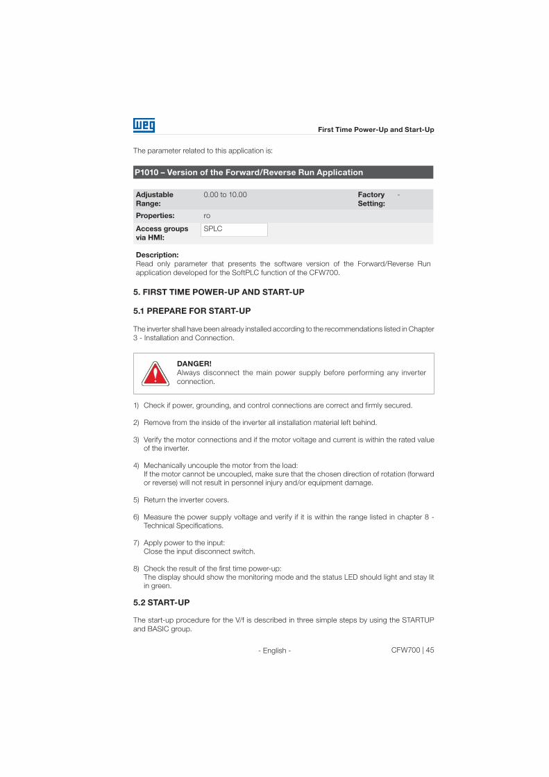
CFW700 | 45
First Time Power-Up and Start-Up
- English -
The parameter related to this application is:
P1010 – Version of the Forward/Reverse Run Application
Adjustable
Range:
0.00 to 10.00 Factory
Setting:
-
Properties: ro
Access groups
via HMI:
SPLC
Description:
Read only parameter that presents the software version of the Forward/Reverse Run
application developed for the SoftPLC function of the CFW700.
5. FIRST TIME POWER-UP AND START-UP
5.1 PREPARE FOR START-UP
The inverter shall have been already installed according to the recommendations listed in Chapter
3 - Installation and Connection.
DANGER!
Always disconnect the main power supply before performing any inverter
connection.
1) Check if power, grounding, and control connections are correct and firmly secured.
2) Remove from the inside of the inverter all installation material left behind.
3) Verify the motor connections and if the motor voltage and current is within the rated value
of the inverter.
4) Mechanically uncouple the motor from the load:
If the motor cannot be uncoupled, make sure that the chosen direction of rotation (forward
or reverse) will not result in personnel injury and/or equipment damage.
5) Return the inverter covers.
6) Measure the power supply voltage and verify if it is within the range listed in chapter 8 -
Technical Specifications.
7) Apply power to the input:
Close the input disconnect switch.
8) Check the result of the first time power-up:
The display should show the monitoring mode and the status LED should light and stay lit
in green.
5.2 START-UP
The start-up procedure for the V/f is described in three simple steps by using the STARTUP
and BASIC group.
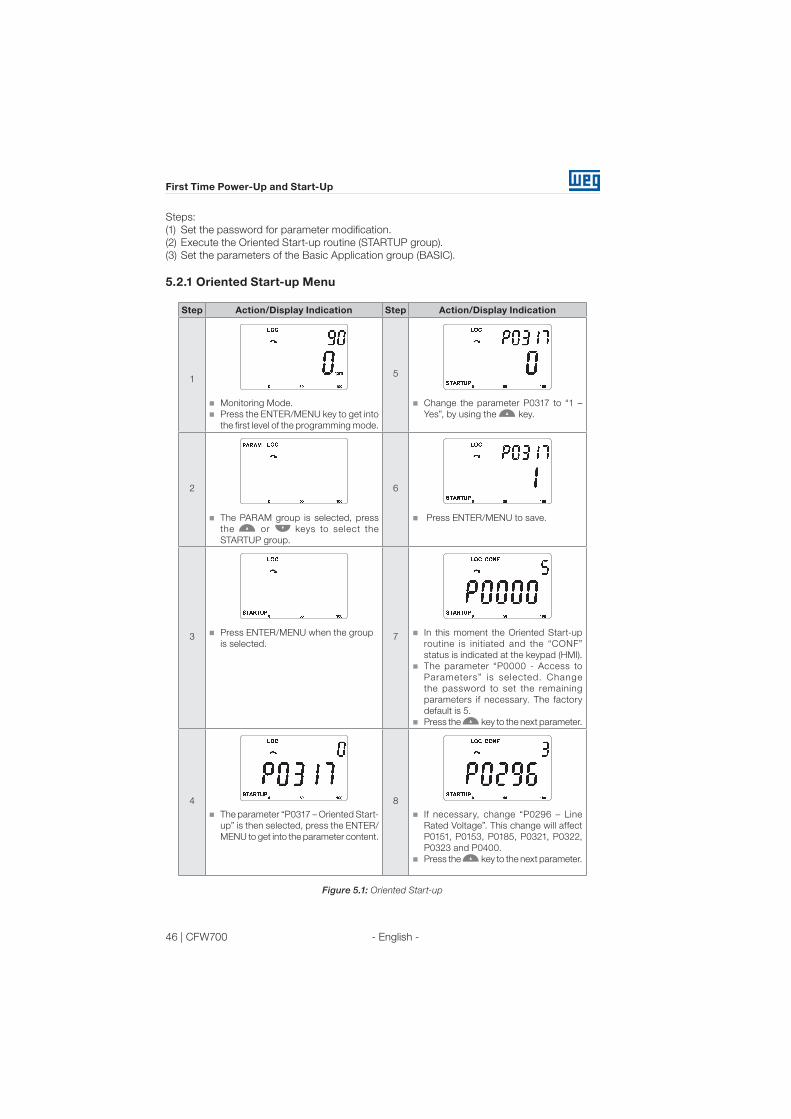
46 | CFW700
First Time Power-Up and Start-Up
- English -
Steps:
(1) Set the password for parameter modification.
(2) Execute the Oriented Start-up routine (STARTUP group).
(3) Set the parameters of the Basic Application group (BASIC).
5.2.1 Oriented Start-up Menu
Step Action/Display Indication Step Action/Display Indication
15
Monitoring Mode.
Press the ENTER/MENU key to get into
the first level of the programming mode.
Change the parameter P0317 to “1 –
Yes”, by using the key.
2 6
The PARAM group is selected, press
the or keys to select the
STARTUP group.
Press ENTER/MENU to save.
3 7Press ENTER/MENU when the group
is selected.
In this moment the Oriented Start-up
routine is initiated and the “CONF”
status is indicated at the keypad (HMI).
The parameter “P0000 - Access to
Parameters” is selected. Change
the password to set the remaining
parameters if necessary. The factory
default is 5.
Press the key to the next parameter.
4 8
The parameter “P0317 – Oriented Start-
up” is then selected, press the ENTER/
MENU to get into the parameter content.
If necessary, change “P0296 – Line
Rated Voltage”. This change will affect
P0151, P0153, P0185, P0321, P0322,
P0323 and P0400.
Press the key to the next parameter.
Figure 5.1: Oriented Start-up

CFW700 | 47
First Time Power-Up and Start-Up
- English -
Step Action/Display Indication Step Action/Display Indication
9 12I f necessar y, change “P0298 –
Application” parameter. This change
will affect P0156, P0157, P0158, P0401,
P0404 and P0410 (this last one only if
P0202 = 0, 1 or 2 - V/f modes). The
time and level of the IGBT overload
protection will also be affected.
Press the key to the next parameter.
If necessary, change “P0400 – Motor
Rated Voltage” parameter. This change
corrects the output voltage by the factor
“x = P0400/P0296”.
Press the key to the next parameter.
10 13If necessary, change “P0202 – Control
Type” parameter. This guide will only
show the setting for P0202 = 0 (V/f 60
Hz) or P0202 = 1 (V/f 50 Hz). Refer to
the Programming and Troubleshooting
Manual for other settings (V/f Adjustable,
VVW or Vector Modes).
Press the key to the next parameter.
If necessary, change “P0401 – Motor
Rated Current” parameter. This change
will affect P0156, P0157, P0158 and
P0410.
Press the key to the next parameter.
11 14
If necessary, change “P0398 – Motor
Service Factor” parameter. This change
will affect the current and the time of the
motor overload protection operation.
Press the key to the next parameter.
If necessary, change “P0404 – Motor
Rated Power” parameter. This change
will affect P0410.
Press the key to the next parameter.
Figure 5.1 (cont.): Oriented Start-up

48 | CFW700
First Time Power-Up and Start-Up
- English -
Step Action/Display Indication Step Action/Display Indication
15 18If necessary, change “P0403 – Motor
Rated Frequency” parameter. This
change will affect P0402.
Press the key to the next parameter.
If necessary, change “P0406 – Motor
Ventilation” parameter.
Press the key to the next parameter.
The parameters to come after selecting
P0406 may vary according to the type
of control set at P0202.
16 19
If necessary, change “P0402 – Motor
Rated Speed”. This change will affect
P0122 to P0131, P0133, P0134, P0135,
P0182, P0208, P0288 and P0289.
Press the key to the next parameter.
If necessary, change “P0408 – Run
Self-Tuning” parameter.
Press the key to the next parameter.
Run the self-tuning when running in
VVW and vector modes.
17 20
If necessary, change “P0405 – Encoder
Pulse Number” according to the
encoder model.
Press the key to the next parameter.
Press the BACK/ESC key to end the
oriented start-up routine.
Press the BACK/ESC again to go back
to the monitoring mode.
Figure 5.1 (cont.): Oriented Start-up

CFW700 | 49
First Time Power-Up and Start-Up
- English -
5.2.2 Basic Application Menu
Step Action/Display Indication Step Action/Display Indication
16
Monitoring Mode.
Press the ENTER/MENU key to get into
the first level of the programming mode.
If necessary, change “P0133 – Minimum
Speed” parameter.
Press the or key to the next
parameter.
2 7
The PARAM group is selected, press the
or keys to select the BASIC
group.
If necessary, change “P0134 – Maximum
Speed” parameter.
Press the or key to the next
parameter.
3 8
Press ENTER/MENU when the group
is selected.
If necessary, change “P0135 – Max.
Output Current” parameter.
Press the or key to the next
parameter.
4 9
In this moment the Basic Application
routine is initiated. If necessary, change
“P0100 – Acceleration Time” parameter.
Press the or key to the next
parameter.
If necessary, change “P0136 – Manual
Torque Boost” parameter.
Press the or key to the next
parameter.
5 10
I f necessar y, change “P0101 –
Deceleration Time”.
Press the or key to the next
parameter.
Press the BACK/ESC key to end the
Basic Application routine.
Press the BACK/ESC again to go back
to the monitoring mode.
Figure 5.2: Basic Application Group

50 | CFW700
Troubleshooting and Maintenance
- English -
6. TROUBLESHOOTING AND MAINTENANCE
6.1 FAULTS AND ALARMS
NOTE!
Refer to the CFW700 Quick Reference guide and the Programming and
Troubleshooting manual for more information about the errors and alarms.
6.2 SOLUTIONS FOR THE MOST FREQUENT PROBLEMS
Table 6.1: Solutions for the most frequent problems
Problem Point to be
Verified Corrective Action
Motor does not start Incorrect wiring
connection
1. Check all power and control connections.
Analog reference
(if used)
1. Check if the external signal is properly connected.
2. Check the status of the control potentiometer (if used).
Incorrect settings 1. Check if parameters are properly set for the application.
Fault 1. Check if the inverter is not blocked due to a fault condition.
2. Check if terminals XC1:15 and 16 and/or XC1:34 and 36
are not shorted (short-circuit at the 24 Vdc power supply).
Motor stall 1. Decrease motor overload.
2. Increase P0136, P0137 (V/f), or P0169/P0170 (vector
control).
Motor speed
fluctuates (oscillates)
Loose connection 1. Stop the inverter, turn off the power supply, and check
and tighten all power connections.
2. Check all internal connections of the inverter.
Defective reference
potentiometer
1. Replace potentiometer.
Oscillation of the
external analog
reference
1. Identify the cause of the oscillation. If it is caused by
electrical noise, use shielded cables or separate from the
power and control wiring.
Incorrect settings
(vector control)
1. Check parameters P0410, P0412, P0161, P0162, P0175,
and P0176.
2. Refer to the Programming and Troubleshooting manual.
Motor speed too
high or too low
Incorrect settings
(reference limits)
1. Check if the values of P0133 (Minimum Speed) and
P0134 (Maximum Speed) are properly set for the motor
and application used.
Control signal
from the analog
reference (if used)
1. Check the level of the reference control signal.
2. Check the settings (gain and offset) of parameters P0232
to P0240.
Motor nameplate 1. Check if the motor has been properly sized for the
application.
Motor does not
reach the rated
speed, or motor
speed starts
oscillating around
the rated speed
(Vector Control)
Settings 1. Decrease P0180.
2. Check P0410.

CFW700 | 51
Troubleshooting and Maintenance
- English -
Problem Point to be
Verified Corrective Action
Off display Keypad
connections
1. Check the inverter keypad connection.
Power supply
voltage
1. Rated values shall be within the limits specified below:
200...240 V power supply: (Sizes A to D) Minimum: 170 V;
Maximum: 264 V;
220-230 V power supply: (Size E) Minimum: 187 V;
Maximum: 253 V;
380...480 V power supply: Minimum: 323 V; Maximum:
528 V.
Mains supply fuses
open
1. Replace fuses.
Motor does not
operate in the field
weakning region
(Vector Control)
Settings 1. Decrease P0180.
Low motor speed
and P0009 = P0169
or P0170 (motor
operating with
torque limitation), for
P0202 = 5 - vector
with encoder
Encoder signals
are inverted or
power connection
is inverted
1. Check the signals A – A, B – B, refer to figure 3.6. If
signals are properly installed, exchange two of the output
phases. For instance U and V.
Encoder cable is
broken
1. Replace the cable.
6.3 INFORMATION FOR CONTACTING TECHNICAL SUPPORT
For technical support and servicing, it is important to have the following information in hand:
Inverter model;
Serial number and manufacturing date available on the identification label of the product (refer
to item 2.5 - Identification Labels and the figure A.2);
Installed software version (check parameter P0023);
Application data and inverter settings.
NOTE!
For information on preventive maintenance, cleaning instructions, removing
and installing the heatsink fan refer to the CFW700 Programming and
Troubleshooting manual.
Table 6.1 (cont.): Solutions for the most frequent problems

52 | CFW700
Option Kits and Accessories
- English -
7. OPTION KITS AND ACCESSORIES
7.1 OPTION KITS
Some models cannot incorporate all available option kits. Refer to table 2.2 for a detailed
description of the option kits that are available for each inverter model.
7.1.1 RFI Filter (only for sizes A, B, C and D) - CFW700...C3...
Reduces the electrical noise from the inverter to the power supply (conducted emissions) in
the high frequency range (> 150 kHz), necessary to accomplish with the maximum levels of
conducted emission specified in the electromagnetic compatibility standards (EN 61800-3 and
EN 55011). Refer to item 3.3 Installation According to the European Directive of Electromagnetic
Compatibility for more details.
7.1.2 Dynamic Braking IGBT (only for size E) - CFW700E...DB...
Refer to item 3.2.3.2 - Dynamic Braking (standard built-in for sizes A, B, C and D and optional
built-in for size E - CFW700...DB...), for more details about the Dynamic Braking.
7.1.3 Nema1 Protection Degree (only for sizes A, B, C and E) - CFW700...N1...
Inverter with Nema1 enclosure. Refer to figure B.7. These inverters have the KN1X-02 kit
(refer to section 7.2 - Accessories).
7.1.4 IP21 Protection Degree (only for sizes A, B and C) - CFW700...21...
Inverter with IP21 enclosure. Refer to Appendix A.7. These inverters have the KIP21X-01 kit
(refer to section 7.2 - Accessories).
7.1.5 Safety Stop - CFW700...Y1...
According to EN 954-1 category 3 (pending certification). Refer to the guide or the CD-ROM
supplied with the product for more information.
7.1.6 24 Vdc External Control Power Supply - CFW700...W1...
The use of this option kit is recommended with communication networks (Profibus, DeviceNet,
etc.), since the control circuit and the network communication interface are kept active (with
power supply and responding to the network communication commands) even in the event of
main power supply interruption. Refer to the guide or the CD-ROM supplied with the product
for more information.
7.2 ACCESSORIES
The accessories are installed to the inverter easily and quickly using the “Plug and Play” concept.
When an accessory is connected to the slots, the control circuit automatically identifies the
model of this accessory and its code is presented in the parameter P0028. The accessory shall
be installed with the inverter power supply off.
The code and model of each available accessory is presented in the table 7.1. The accessories
can be ordered individually and they will be provided in their own packaging containing the
components and guides with detailed instructions for installation, operation and programming.
Table 7.1: Accessory models

CFW700 | 53
Option Kits and Accessories
- English -
WEG Part
NumberName Description Slot
Identification
Parameters
- P0028
Control Accessories
11511558 USB-RS485/
RS422 Kit conversor USB-RS485/RS422 - -
11008106 CAN-01 CAN interface module (CANopen / DeviceNet). 3 CD--
11045488 PROFIBUS DP-01 Profibus DP interface module. 3 C9--
Flash Memory Module
11355980 MMF-02 FLASH memory module. 5 --xx(1)
Expansion Module
11402038 CCK-01 Output relays module. - -
Stand-alone Keypad, Blank Cover, and Frame for Remote Mounted Keypad
11401784 HMI-02 CFW700 stand-alone keypad (HMI).(2) HMI -
11342535 RHMIF-02 Remote keypad frame kit (IP56). - -
10950192 CAB-RS-1M Remote Keypad Cable – 1 m - -
10951226 CAB-RS-2M Remote Keypad Cable – 2 m - -
10951223 CAB-RS-3M Remote Keypad Cable – 3 m - -
10951227 CAB-RS-5M Remote Keypad Cable – 5 m - -
10951240 CAB-RS-7.5M Remote Keypad Cable – 7.5 m - -
10951239 CAB-RS-10M Remote Keypad Cable – 10 m - -
11010298 HMID-01 Blank cover for the keypad slot. HMI -
Miscellaneous
11401877 KN1A-02 Nema1 kit for size A inverter. (3) - -
11401938 KN1B-02 Nema1 kit for size B inverter. (3) - -
11401857 KN1C-02 Nema1 kit for size C inverter. (3) - -
10960842 KN1E-01 Nema1 kit for models 105 A and 142 A of size E inverter. (3) - -
10960850 KN1E-02 Nema1 kit for models 180 and 211 A of size E inverter. (3) - -
11401939 KIP21A-01 IP21 kit for size A inverter. - -
11401941 KIP21B-01 IP21 kit for size B inverter. - -
11401940 KIP21C-01 IP21 kit for size C inverter. - -
11010264 KIP21D-01 IP21 kit for size D inverter. - -
11010265 PCSA-01 Kit for power cables shielding - frame A. - -
11010266 PCSB-01 Kit for power cables shielding - frame B. - -
11010267 PCSC-01 Kit for power cables shielding - frame C. - -
11119781 PCSD-01Kit for power cables shielding - frame D (included in the
standard product).- -
10960844 PCSE-01Kit for power cables shielding - frame E (included in the
standard product).- -
10960847 CCS-01Kit for control cables shielding (included in the standard
product).- -
11401942 CONRA-02CFW700 Control Rack (includes the CC700.CDE control
board and it is supplied with the product). - -
10790788 DBW-03 Módulo Frenagem DBW030380D3848SZ - -
Notes:(1) The identification of the MMF-02 module is presented in the bit 6 of the parameter P0028. Refer to CFW700 Programming
and Troubleshooting Manual.
(2) Use DB-9 pin, male-to-female, straight-through cable (serial mouse extension type) for connecting the keypad to the
inverter or Null-Modem standard cable. Maximum cable length: 10 m (33 ft).
Examples:
- Mouse extension cable - 1.80 m (6 ft); Manufacturer: Clone.
- Belkin pro series DB9 serial extension cable 5 m (17 ft); Manufacturer: Belkin.
- Cables Unlimited PCM195006 cable, 6 ft DB9 m/f; Manufacturer: Cables Unlimited.
(3) Refer to figure B.7.

54 | CFW700
Technical Specifications
- English -
8. TECHNICAL SPECIFICATIONS
8.1 POWER DATA
Power Supply:
Tensão nominal máxima: 240 V para modelos 200...240 V, 240 V para modelos 220-230 V e
480 V para modelos 380...480 V para altitude até 2000 m. Para altitude maior a redução da
tensão será de 1,1 % para cada 100 m acima de 2000 m - altitude máxima: 4000 m.
Voltage tolerance: -15 % to +10 %.
Frequency: 50/60 Hz (48 Hz to 62 Hz).
Phase imbalance: ≤3 % of the rated phase-to-phase input voltage.
Overvoltage according to Category III (EN 61010/UL 508C).
Transient voltage according to Category III.
Maximum of 60 connections per hour (1 per minute).
Typical efficiency: ≥ 97 %.
Typical input power factor:
- 0.94 for three-phase power supply models in the rated conditions.
- 0.70 for single-phase power supply models in the rated conditions.
Refer to Appendix B for more information about the technical specifications.
8.2 ELECTRICAL/GENERAL SPECIFICATIONS
Table 8.1: Electrical/general specifications
CONTROL METHOD Voltage source
Type of control:
- V/f (Scalar);
- VVW: Voltage Vector Control;
- Vector control with encoder;
- Sensorless vector control (without encoder).
PWM SVM (Space Vector Modulation);
Full digital (software) current, flux, and speed regulators.
Execution rate:
- current regulators: 0.2 ms (5 kHz)
- flux regulator: 0.4 ms (2.5 kHz)
- speed regulator / speed measurement: 1.2 ms.
OUTPUT
FREQUENCY
0 to 3.4 x rated motor frequency (P0403). The rated frequency is
programmable from 0 Hz to 300 Hz in the scalar mode and from 30
Hz to 120 Hz in the vector mode.
PERFORMANCE SPEED
CONTROL
V/f (Scalar):
Regulation (with slip compensation): 1 % of the rated speed.
Speed variation range: 1:20.
VVW:
Regulation: 1 % of the rated speed.
Speed variation range: 1:30.
Sensorless:
Regulation: 0.5 % of the rated speed.
Speed variation range: 1:100.
Vector with Encoder:
Regulation:
- ±0.1 % of the rated speed with a digital reference (Keypad, Serial,
Fieldbus, Electronic Potentiometer, Multispeed);
- ±0.2 % of the rated speed with a 12-bits analog input.
TORQUE
CONTROL
Range: 10 to 180 %, regulation: ±5 % of the rated torque (with encoder);
Range: 20 to 180 %, regulation: ±10 % of the rated torque (sensorless
above 3 Hz).

CFW700 | 55
Technical Specifications
- English -
USER’S POWER
SUPPLIES
(CC700 board)
REF
(XC1:21-24)
10 V ± 10 % power supply to be used with the potentiometer at the
analog inputs.
Maximum output current: 2 mA.
+5V-ENC
(XC1:1-8)
5 V ± 5 % power supply for the encoder.
Maximum output current: 160 mA.
+24 V 24 V ± 10 % power supply to be used with the digital inputs/outputs.
Maximum output current: 500 mA.
INPUTS
(CC700
board)
ANALOG 2 differential inputs;
Resolution: 11 bits + signal.
Input levels: (0 to 10) V, (-10 to 10) V, (0 to 20) mA or (4 to 20) mA.
Impedance: 400 kΩ for the voltage input, 500 Ω for the current input.
Maximum input voltage: ± 15 V.
Programmable functions.
DIGITAL 8 isolated digital inputs.
24 Vdc (High level ≥ 10 V, Low level ≤ 2 V).
Maximum input voltage: ± 30 Vdc.
Input impedance: 2 kΩ.
Active high or active low input selectable by jumper (simultaneous
selection for all inputs).
OUTPUTS
(CC700
board)
ANALOG 2 non isolated outputs.
Voltage (0 to 10 V) or current (0/4 mA to 20 mA) output.
Maximum load: RL ≥ 10 kΩ (voltage) or RL ≤ 500 Ω (current).
Resolution: 10 bits.
Programmable functions.
RELAY 1 relay (NO/NC).
Maximum voltage: 240 Vac / 30 Vdc.
Maximum current: 0.75 A.
Programmable functions.
TRANSISTOR 4 open collector isolated digital outputs (with the same reference as
the 24 V power supply).
Maximum current: 100 mA.
Maximum voltage: 30 Vdc.
Programmable functions.
SAFETY PROTECTION Output overcurrent/short-circuit.
Under/Overvoltage.
Phase loss.
Overtemperature of the heatsink/internal air.
IGBTs overload.
Motor overload.
External fault / alarm.
CPU or memory fault.
Output phase-ground short-circuit.
INTEGRAL
KEYPAD
(HMI)
STANDARD
KEYPAD
9 operator keys: Start/Stop, Up arrow, Down arrow, Direction of
rotation, Jog, Local/Remote, BACK/ESC and ENTER/MENU.
LCD display.
View/edition of parameters.
Indication accuracy:
- current: 5 % of the rated current;
- speed resolution: 1 rpm.
Possibility of remote mounting.
Table 8.1 (cont.): Electrical/general specifications
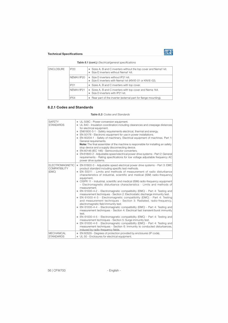
56 | CFW700
Technical Specifications
- English -
ENCLOSURE IP20 Sizes A, B and C inverters without the top cover and Nema1 kit.
Size E inverters without Nema1 kit.
NEMA1/IP20 Size D inverters without IP21 kit.
Size E inverters with Nema1 kit (KN1E-01 or KN1E-02).
IP21 Sizes A, B and C inverters with top cover.
NEMA1/IP21 Sizes A, B and C inverters with top cover and Nema 1kit.
Size D inverters with IP21 kit.
IP54 Rear part of the inverter (external part for flange mounting).
8.2.1 Codes and Standards
Table 8.2: Codes and Standards
SAFETY
STANDARDS
UL 508C - Power conversion equipment.
UL 840 - Insulation coordination including clearances and creepage distances
for electrical equipment.
EN61800-5-1 - Safety requirements electrical, thermal and energy.
EN 50178 - Electronic equipment for use in power installations.
EN 60204-1 - Safety of machinery. Electrical equipment of machines. Part 1:
General requirements.
Note: The final assembler of the machine is responsible for installing an safety
stop device and a supply disconnecting device.
EN 60146 (IEC 146) - Semiconductor converters.
EN 61800-2 - Adjustable speed electrical power drive systems - Part 2: General
requirements - Rating specifications for low voltage adjustable frequency AC
power drive systems.
ELECTROMAGNETIC
COMPATIBILITY
(EMC)
EN 61800-3 - Adjustable speed electrical power drive systems - Part 3: EMC
product standard including specific test methods.
EN 55011 - Limits and methods of measurement of radio disturbance
characteristics of industrial, scientific and medical (ISM) radio-frequency
equipment.
CISPR 11 - Industrial, scientific and medical (ISM) radio-frequency equipment
– Electromagnetic disturbance characteristics - Limits and methods of
measurement.
EN 61000-4-2 - Electromagnetic compatibility (EMC) - Part 4: Testing and
measurement techniques - Section 2: Electrostatic discharge immunity test.
EN 61000-4-3 - Electromagnetic compatibility (EMC) - Part 4: Testing
and measurement techniques - Section 3: Radiated, radio-frequency,
electromagnetic field immunity test.
EN 61000-4-4 - Electromagnetic compatibility (EMC) - Part 4: Testing and
measurement techniques - Section 4: Electrical fast transient/burst immunity
test.
EN 61000-4-5 - Electromagnetic compatibility (EMC) - Part 4: Testing and
measurement techniques - Section 5: Surge immunity test.
EN 61000-4-6 - Electromagnetic compatibility (EMC) - Part 4: Testing and
measurement techniques - Section 6: Immunity to conducted disturbances,
induced by radio-frequency fields.
MECHANICAL
STANDARDS
EN 60529 - Degrees of protection provided by enclosures (IP code).
UL 50 - Enclosures for electrical equipment.
Table 8.1 (cont.): Electrical/general specifications

Índice
- Español -
Índice
1. INSTRUCCIONES DE SEGURIDAD ..............................................591.1 AVISOS DE SEGURIDAD EN EL MANUAL ..........................................59
1.2 AVISOS DE SEGURIDAD EN EL PRODUCTO.....................................59
1.3 RECOMENDACIONES PRELIMINARES..............................................60
2. INFORMACIONES GENERALES...................................................612.1 SOBRE EL MANUAL .............................................................................61
2.2 SOBRE EL CFW700...............................................................................61
2.3 NOMENCLATURA .................................................................................63
2.4 LISTA DE LOS MODELOS DISPONIBLES...........................................64
2.5 ETIQUETAS DE IDENTIFICACIÓN DEL CFW700 ...............................64
2.6 RECIBIMIENTO Y ALMACENADO.......................................................65
3. INSTALACIÓN Y CONEXIÓN.........................................................663.1 INSTALACIÓN MECÁNICA ...................................................................66
3.1.1 Condiciones Ambientales...........................................................66
3.1.2 Posicionamiento y Fijación ........................................................66
3.2 INSTALACIÓN ELÉCTRICA ..................................................................67
3.2.1 Identificación de los Bornes de Potencia y Puntos de
Puesta a Tierra......................................................................................67
3.2.2 Cableado de Potencia, Puesta a Tierra y Fusibles .................68
3.2.3 Conexiones de Potencia.............................................................69
3.2.3.1 Conexiones de Entrada ...........................................................69
3.2.3.2 Frenado Reostático (incluído en el producto estándar
para los tamaños A, B, C y D y opcional para el tamaño E -
CFW700...DB...) .....................................................................................70
3.2.3.3 Conexiones de Salida..............................................................71
3.2.4 Conexiones de Puesta a Tierra .................................................72
3.2.5 Conexiones de Control...............................................................73
3.2.6 Distancia para Separación de Cables ......................................76
3.3 INSTALACIONES DE ACUERDO CON LA DIRECTIVA EUROPEA
DE COMPATIBILIDAD ELECTROMAGNÉTICA.........................................77
3.3.1 Instalación Conforme..................................................................77
3.3.2 Niveles de Emisión y Inmunidad Cumplidos ...........................78
4. HMI Y PROGRAMACIÓN BÁSICA.................................................794.1 INTERFAZ HOMBRE MÁQUINA HMI -CFW700..................................79
4.2 APLICATIVOS.........................................................................................82
4.2.1 Aplicativo Regulador PID (P1003 = 1)........................................82
4.2.1.1 PID Académico .........................................................................88
4.2.2 Aplicativo Potenciómetro Electrónico (P.E.) (P1003 = 2) .......89
4.2.2.1 Descripción y Definiciones .....................................................89
4.2.2.2 Colocación en Funcionamiento .............................................90
4.2.2.3 Parámetros ...............................................................................91
4.2.3 Aplicativo Multispeed ................................................................92
4.2.4 Aplicativo Comando a Tres Cables (Start / Stop) ..................96
4.2.5 Aplicativo Comando Avance y Retorno (P1003 = 5)................97

Índice
- Español -
5. ENERGIZACIÓN Y PUESTA EN MARCHA .................................1005.1 PREPARACIÓN Y ENERGIZACIÓN....................................................100
5.2 PUESTA EN MARCHA.........................................................................100
5.2.1 Menú STARTUP - Start-up Orientado.....................................101
5.2.2 Menú BASIC - Aplicación Básica ............................................104
6. DIAGNÓSTICO DE PROBLEMAS Y MANTENIMIENTO............1056.1 FALLAS Y ALARMAS...........................................................................105
6.2 SOLUCIONES DE LOS PROBLEMAS MÁS FRECUENTES .............105
6.3 DATOS PARA CONTACTAR CON LA ASISTENCIA TÉCNICA.........106
7. OPCIONALES Y ACCESORIOS ................................................... 1077.1 OPCIONALES .......................................................................................107
7.1.1 Filtro Supresor de RFI (solamente tamaños A, B, C y D) -
CFW700...C3... ....................................................................................107
7.1.2 IGBT de Frenado Reostático (solamente tamaño E) -
CFW700E...DB.....................................................................................107
7.1.3 Grau de Protección Nema1 (solamente tamaños
A, B, C y E) - CFW700...N1... ..............................................................107
7.1.4 Grau de Protección IP21 (solamente A, B y C) -
CFW700...21.........................................................................................107
7.1.5 Parada de Seguridad - CFW700...Y1........................................107
7.1.6 Alimentación Externa del Control en 24 Vcc -
CFW700...W1... ....................................................................................107
7.2 ACCESORIOS.......................................................................................107
8. ESPECIFICACIONES TÉCNICAS ................................................1098.1 DATOS DE POTENCIA.........................................................................109
8.2 DATOS DE LA ELECTRÓNICA/GENERALES ...................................109
8.2.1 Normativas Atendidas .............................................................. 111
ANEXO A - DIAGRAMAS Y FIGURAS.............................................165
ANEXO B – ESPECIFICACIONES TÉCNICAS ................................ 173

CFW700 | 59 - Español -
Instrucciones de Seguridad
1. INSTRUCCIONES DE SEGURIDAD
Este manual contiene las informaciones necesarias para el uso correcto del convertidor de
frecuencia CFW700.
Este manual fue desarrollado para que sea utilizado por personas con entrenamiento o
calificación técnica adecuados para operar este tipo de equipamiento. Estas personas deben
seguir las instrucciones de seguridad definidas por normas locales. No seguir las instrucciones
de seguridad puede resultar en riesgo de muerte y/o daños al equipamiento.
1.1 AVISOS DE SEGURIDAD EN EL MANUAL
¡PELIGRO!
Los procedimientos recomendados en este aviso tienen como objetivo proteger
al usuario contra muerte, heridas graves y daños materiales considerables.
¡ATENCIÓN!
Los procedimientos recomendados en este aviso tienen como objetivo evitar
daños materiales.
¡NOTA!
El texto suministra informaciones importantes para la correcta comprensión y
bueno funcionamiento del producto.
1.2 AVISOS DE SEGURIDAD EN EL PRODUCTO
Tensiones elevadas presentes.
Componentes sensibles a descargas electrostáticas. No tocarlos.
Conexión obligatoria de puesta a tierra de protección (PE).
Conexión del blindaje al tierra.
Superficie caliente.
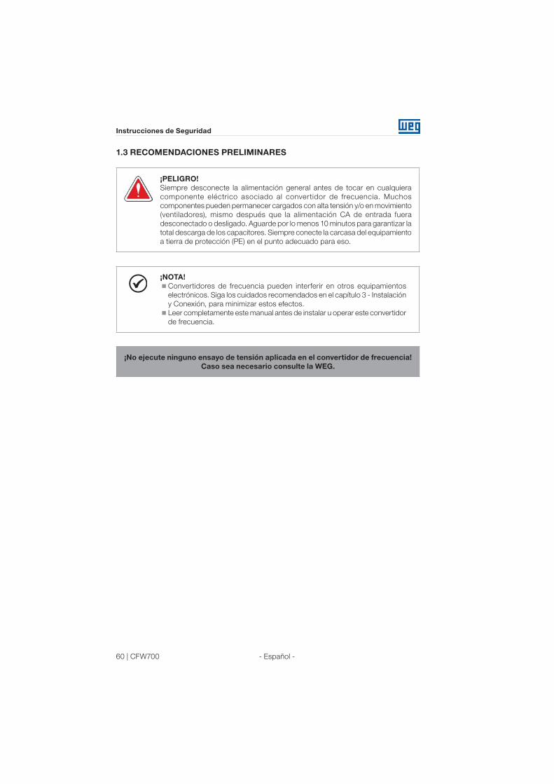
60 | CFW700 - Español -
Instrucciones de Seguridad
1.3 RECOMENDACIONES PRELIMINARES
¡PELIGRO!
Siempre desconecte la alimentación general antes de tocar en cualquiera
componente eléctrico asociado al convertidor de frecuencia. Muchos
componentes pueden permanecer cargados con alta tensión y/o en movimiento
(ventiladores), mismo después que la alimentación CA de entrada fuera
desconectado o desligado. Aguarde por lo menos 10 minutos para garantizar la
total descarga de los capacitores. Siempre conecte la carcasa del equipamiento
a tierra de protección (PE) en el punto adecuado para eso.
¡NOTA!
Convertidores de frecuencia pueden interferir en otros equipamientos
electrónicos. Siga los cuidados recomendados en el capítulo 3 - Instalación
y Conexión, para minimizar estos efectos.
Leer completamente este manual antes de instalar u operar este convertidor
de frecuencia.
¡No ejecute ninguno ensayo de tensión aplicada en el convertidor de frecuencia!
Caso sea necesario consulte la WEG.

CFW700 | 61
Informaciones Generales
- Español -
2. INFORMACIONES GENERALES
2.1 SOBRE EL MANUAL
Este manual presenta informaciones para la adecuada instalación y operación del convertidor,
colocación en funcionamento en el modo de control V/f (escalar), las principales características
técnicas y como identificar y corregir los problemas más comunes de los diversos modelos de
convertidores de la línea CFW700.
¡ATENCIÓN!
La operación de este equipamiento requiere instrucciones de instalación y
operación detalladas, suministradas en el manual del usuario, manual de
programación y manuales de comunicación. El manual del usuario y la referencia
rápida de los parámetros son suministrados impresos en la adquisición del
convertidor, ya los guías son suministrados impresos junto con su respectivo
accesorio, los demás manuales son suministrados apenas en formato
electrónico en el CD-ROM que acompaña el convertidor o pueden ser obtenidos
en el sitio de la WEG - www.weg.net. El CD deberá siempre mantenerse con
este equipamiento. Una copia impresa de los archivos disponibilizados en el
CD puede solicitarse por medio de su representante local WEG.
Parte de las figuras y tablas están disponibilizadas en los anexos, los cuales están divididos en anexo
A para figuras y anexo B para especificaciones técnicas. Las informaciones están en tres idiomas.
Para más informaciones, consultar la documentación técnica:
Manual de Programación y Mantenimiento CFW700;
Manual del Usuario DeviceNet;
Manual del Usuario CANopen;
Manual del Usuario Profibus DP;
Manual del Usuario Modbus.
2.2 SOBRE EL CFW700
El convertidor de frecuencia CFW700 es un producto de alto desempeño que permite el control
de velocidad y del torque (par) de motores de inducción trifásicos. La característica central de
este producto es la tecnologia “Vectrue”, la cual presenta las siguientes ventajas:
Control escalar (V/f), VVW o control vectorial programables en el mismo producto.
El control vectorial puede ser programado como “sensorles” (lo que significa motores
padrones, sin necesidad de encoder) o como control vectorial con encoder en el motor.
El control vectorial “sensorles” permite alto torque (par) y rapidez en la respuesta, mismo en
velocidades muy bajas o en el arranque.
El control vectorial con encoder posibilita alto grado de exactitud en el accionamiento, para
todo el rango de velocidad (hasta con el motor parado).
Función “Frenado Optimo” para el control vectorial, permitiendo el frenado controlado del
motor, eliminando en algunas aplicaciones la resistencia de frenado adicional.
Función “Autoajuste” para el control vectorial, permitiendo el ajuste automático de los
reguladores y parámetros de control, a partir de la identificación (también automática) de los
parámetros del motor y de la carga utilizada.
Los principales componentes del CFW700 pueden ser verificados en la figura A.1.

62 | CFW700
Informaciones Generales
- Español -
Entradas
Analógicas
AI1 y AI2
Módulo de
Memória
FLASH
(Slots)
Entradas
Digitales
DI1 a DI8
Fuentes para electrónica y interfaces
entre potencia y controlRS-485
PC
POTENCIA
CONTROL
Retificador
trifásico
Filtro C3 (*)
(disponible en
los convertidores
CFW700...C3...)
Motor
U/T1
V/T2
W/T3
DC+ DC-BR
Convertidor
con
transistores
IGBT
Red de
alimentación
R/L1/L
S/L2/N
T/L3
= Conexión del barramiento CC
= Conexión para el
resistor de frenado
Précarga
Software WPS
Software WLP
Ind
uto
res L
ink C
C
Ban
co
de c
on
den
sad
ore
s
Lin
k C
C
IGB
T d
e f
ren
ad
o
(d
isp
on
ible
en lo
s
co
nvert
ido
res C
FW
70
0...D
B...)
Filtro RFI
HMI
CC700
Tarjeta de
Control
con CPU
32 bits
“RISC”
Salidas
Analógicas
AO1 y AO2
Salida Digital
DO1 (RL1)
Salidas
Digitales
DO2 a DO5
HMI (remota)
Realimentaciones:
- tensión
- corriente
PEPE
COMM 1
(Slot 3 - Verde)
Accesorios
= Interface hombre-máquina
(*) El capacitor contra tierra del filtro C3 debe desconectarse para redes IT y
para delta puesta a tierra. Consulte el ítem 3.2.3.1. - Conexiones de Entrada.
Figura 2.1: Diagrama de bloque del CFW700

CFW700 | 63
Informaciones Generales
- Español -
2.3 NOMENCLATURA
Tabla 2.1: Nomenclatura de los convertidores CFW700 - campos utilizados.
Producto
y serie
Identificación del modelo
Frenado (1)
Grado de
protección
(1)
Nivel de
emisión
conducida
(1)
Parada de
seguridad
(3)
Alimentación
externa para
control
Versión de
hardware
especial
Versión de
Software
especialTamañoCorriente
nominal
N° de
fases
Tensión
nominal
Ex.: CFW700 A 03P6 T 4 DB 20 C3 Y1 W1 --- --
Op
cio
nes d
isp
on
ible
s
CFW700
Consulte la tabla 2.2.En blanco =
padrón.
DB = sin frenado reostático (válido solamente para
convertidores del tamaño E).
Sx =
software
especial.
DB = con frenado reostático. En blanco = padrón.
20 = IP20 (2) Hxx o Kxx = hardware
especial.
21 = IP21 (no disponible para el tamaño E). En blanco = no posee.
N1 = gabinete Nema1 (tipo 1 conforme UL) (grado de
protección de acuerdo con la normativa IEC es IP21 para los
tamaños A, B y C, y IP20 para los tamaño D y E).
W1 = alimentación independiente de la
electrónica en 24 Vcc.
En blanco = no posee.
En blanco = no atiende niveles de normas de emisión conducida.Y1 = com función de parada de seguridad
conforme EN 954-1/ISO 13849-1, categoría 3.C3 = conforme categoría 3 (C3) de la IEC 61800-3, con filtro RFI interno.
Notas: (1) Las opciones disponibles para cada modelo están presentadas en la tabla 2.2.
(2) Esta opción no está disponible para los modelos del tamaño D (el producto estándar es Nema1).
(3) Esta opción no está disponible para los modelos del tamaño A con la opción N1 (gabinete Nema1) o IP21.
Tabla 2.2: Opciones disponibles para cada campo de la nomenclatura conforme el tamaño, el número
de fases de alimentación, la corriente y tensión nominales del convertidor
Tamaño
Corriente nominal
de salida para uso
en régimen ND
Nº de fasesTensión
nominal
Opciones disponibles para los demás campos de la
nomenclatura del convertidor (el producto estándar
tiene la opción en negrito)
FrenadoGrado de
protección
Nivel de emisión
conducida
A06P0 = 6.0 A B = alimentación
monofásica o trifásica2 = 200…240 V DB 20, 21 o N1 En Blanco
07P0 = 7.0 A
A
06P0 = 6.0 AS = alimentación
monofásica2 = 200…240 V DB 20, 21 o N1
C307P0 = 7.0 A
10P0 = 10 A En Blanco o C3
A
07P0 = 7.0 A
T = alimentación
trifásica
2 = 200…240 V DB
20, 21 o N1
En Blanco o C3
10P0 = 10 A
13P0 = 13 A
16P0 = 16 A
B
24P0 = 24 A
28P0 = 28 A
33P5 = 33.5 A
C
45P0 = 45 A
54P0 = 54 A
70P0 = 70 A
D86P0 = 86 A
21 o N10105 = 105 A
E
0142 = 142 A
2 = 220…230 V NB o DB 20 o N1 C30180 = 180 A
0211 = 211 A
A
03P6 = 3.6 A
T = alimentación
trifásica4 = 380-480 V
DB
20, 21 o N1
En Blanco o C3
05P0 = 5.0 A
07P0 = 7.0 A
10P0 = 10 A
13P5 = 13.5 A
B
17P0 = 17 A
24P0 = 24 A
31P0 = 31 A
C
38P0 = 38 A
45P0 = 45 A
58P5 = 58.5 A
D70P5 = 70.5 A
21 o N188P0 = 88 A
E
0105 = 105 A
NB o DB 20 o N1 C30142 = 142 A
0180 = 180 A
0211 = 211 A

64 | CFW700
Informaciones Generales
- Español -
2.4 LISTA DE LOS MODELOS DISPONIBLES
Los modelos de convertidores disponibles son listados en las tablas B.1 y B.2.
2.5 ETIQUETAS DE IDENTIFICACIÓN DEL CFW700
Existen dos etiquetas de identificación, una completa, ubicada en la lateral del convertidor y
otra resumida debajo de la HMI. Consulte la figura A.2 para verificar la localización de estas
etiquetas en el producto. La etiqueta debajo de la HMI permite identificar las características
más importantes, mismo en convertidores fijados lado a lado. Cuando huviera más de un
convertidor, atención para no cambiar las tapas (tapa frontal en el caso de los tamaños A, B o
C y la tapa del rack de control en el caso de los tamaños D y E) entre los convertidores, pues
en la etiqueta por debajo de la HMI hay informaciones sobre cada convertidor.
Modelo del CFW700
Fecha de fabricaciónÍtem WEG (n° de material)
Nº de serie
(a) Etiqueta de identificación debajo de la HMI.
Modelo del CFW700
Ítem WEG (n° de material)
Fecha de fabricación
Peso neto del convertidor de
frecuencia (masa)
Dados nominales de entrada
(tensión, nº de fases, corrientes
nominales para uso com
régimen de sobrecarga ND y
HD, frecuencia)
Dados nominales de salida
(tensión, nº de fases,
corrientes nominales
para uso con régimen
de sobrecarga ND y HD,
corrientes de sobrecarga
para
1 min y 3 s y rango de
frecuencia)
Temperatura ambiente
nominal máxima (sin
derrateo) para régimen
de sobrecarga ND y
con espacios libres de
ventilación alrededor del
convertidor (consulte las
cotas A, B, C y D en la
tabla B.8)
N° de serie
Especificaciones de corriente
para uso con régimen de
sobrecarga normal (ND)
Especificaciones de corriente
para uso com régimen de
sobrecarga pesada (HD)
(b) Etiqueta de identificación lateral del convertidor de frecuencia.
Figura 2.2 (a) y (b): Etiquetas de identificación

CFW700 | 65
Informaciones Generales
- Español -
2.6 RECIBIMIENTO Y ALMACENADO
El CFW700 es suministrado embalado en caja de cartón hasta los modelos del tamaño C.
Los modelos en gabinetes mayores son embalados en caja de madera. En la parte externa
del embalaje existe una etiqueta de identificación, la misma que está fijada en el lateral del
convertidor CFW700.
Siga los procedimientos abajo para abrir el embalaje de modelos mayores que el tamaño C:
1- Coloque la caja sobre una mesa con el auxilio de dos personas;
2- Abra el embalaje;
3- Retire la protección de cartón o poliestireno.
Verifique si:
La etiqueta de identificación del CFW700 corresponde al modelo comprado;
Ocurrieron daños durante el transporte.
Caso sea detectado algún problema, contacte inmediatamente la empresa transportadora.
Si el CFW700 no fuera instalado pronto, almacenarlo en un lugar limpio y seco (temperatura
entre -25 °C y 60 °C) con una cobertura para evitar la entrada de polvo al interior del convertidor.
¡ATENCIÓN!
Cuando el convertidor es almacenado por largos periodos de tiempo es
necesario hacer el “reforming” de los condensadores (capacitores). Consulte
el procedimiento en el ítem Mantenimiento Preventivo en el manual de
programación y mantenimiento del CFW700.
66 | CFW700
Instalación y Conexión
- Español -
3. INSTALACIÓN Y CONEXIÓN
3.1 INSTALACIÓN MECÁNICA
3.1.1 Condiciones Ambientales
Evitar:
Exposición directa a los rayos solares, lluvia, humedad excesiva y ambientes salinos;
Gases o líquidos explosivos o corrosivos;
Vibraciones excesiva;
Polvo, partículas metálicas o aceite suspenso en el aire.
Condiciones ambientales permitidas para el funcionamiento:
Temperatura alrededor del convertidor: de -10 ºC hasta el valor de Ta conforme presentado
en la tabla B.3.
Para temperatura alrededor del convertidor mayor que Ta y menor que 60 °C (modelos de
los tamaños A, B, C y D) y 55 °C (modelos del tamaño E) es necesario aplicar reducción de
la corriente de 2 % para cada grado Celsius arriba de Ta.
Humedad relativa del aire: de 5 % a 90 % sin condensación.
Altitud máxima: hasta 1000 m - condiciones nominales.
De 1000 m a 4000 m - reducción de la corriente de 1 % para cada 100 m arriba de 1000 m
de altitud.De 2000 metros a 4000 m por encima del nivel del mar - aplicar 1,1 % de reducción
de la tensión máxima (240 Vca para los modelos 200...230 Vca, 230 vca para los modelos
220...230 Vca y 480 Vca para los modelos 380...480 Vca) para cada 100 metros por encima
de 2000 metros.
Grado de contaminación: 2 (conforme EN50178 y UL508C), con contaminación no conductiva.
La condensación no debe causar conducción de los residuos acumulados.
3.1.2 Posicionamiento y Fijación
Dimensiones externas, posición de los orificios de fijación y peso líquido (masa) del convertidor
conforme las tablas B.7 y B.8. Para más detalles de cada tamaño consulte las figuras de B.9
hasta B.13.
Instale el convertidor en la posición vertical en una superfície plana. Coloque primeiro los
tornillos en la superfície donde el convertidor será instalado, instale el convertidor y entonces
apriete los tornillos.
Convertidores del tamaño E con opción N1 (CFW700E...N1...):
Después de fijar el convertidor, instale la parte superior del kit Nema 1 en el convertidor
utilizando los 2 tornillos M8 suministrados con el producto.
Dejar como mínimo los espacios libres indicados en la tabla B.8, de forma a permitir circulación
del aire de refrigeración. Es posível montar los convertidores de los tamaños A, B y C con
grado de protección IP20 (CFW700...20...) lado a lado sin espacio lateral, o sea, con la cota D
de la tabla B.8 igual a cero.
No poner componentes sensibles al calor luego arriba del convertidor de frecuencia.
¡ATENCIÓN!
Cuando un convertidor de frecuencia es instalado arriba de otro, usar la
longitud mínima A + B (tabla B.8) y apartar del convertidor superior el aire
caliente que viene del convertidor abajo.
Prever electroducto o conducto independiente para la separación física
de los conductores de la señal, de control y de potencia (consulte ítem
3.2 – Instalación Eléctrica).

CFW700 | 67
Instalación y Conexión
- Español -
Para datos referentes al montaje en superfície y en brida consulte el anexo B.8. La potencia
disipada por el convertidor en la condición nominal para montaje en superfície y brida es
presentada en la tabla B.3. En el caso de montaje en brida, remover soportes de fijación
del convertidor. La parte del convertidor que queda para fuera del tablero posee grado de
protección IP54. Para garantizar el grado de protección del tablero es necesario prever
vedación adecuada del orifício realizado para el pasaje del disipador del convertidor. Ejemplo:
usar vedación con silicona.
Para detalles sobre el acceso a los bornes de control y de potencia, consulte la figura A.4.
3.2 INSTALACIÓN ELÉCTRICA
¡PELIGRO!
Las informaciones que siguen tiene el propósito de orientar a la obtención
de una instalación eléctrica correcta. Seguir también las normativas de
instalaciones eléctricas aplicables.
Certifíquese que la red de alimentación esta desconectada (sin corriente)
antes de iniciar las conexiones.
3.2.1 Identificación de los Bornes de Potencia y Puntos de Puesta a Tierra
Puesta a TierraPuesta a Tierra
R/L1 S/L2 T/L3 DC- DC+ U/T1 V/T2 W/T3BR
(a) Tamaños A, B y C
Puesta a Tierra Puesta a Tierra
(b) Tamaño D
R/L1 S/L2 T/L3 DC- DC+ U/T1 V/T2 W/T3BR
R/L1, S/L2, T/L3: red de alimentación
CA.
DC-: polo negativo de la tensión del
Bus CC.
BR: conexión de la resistencia de
frenado.
DC+: polo positivo de la tensión del Bus
CC.
U/T1, V/T2, W/T3: conexiones para
el motor.
Figura 3.1 (a) y (b): Bornes de potencia y puntos de puesta a tierra – tamaños A a E

68 | CFW700
Instalación y Conexión
- Español -
Puesta a Tierra
(4xM8, 4xM5)
(c) Tamaño E
R/L1, S/L2, T/L3: red de alimentación CA.
U/T1, V/T2, W/T3: conexiones para el
motor.
DC+: polo positivo de la tensión del Bus CC.
BR: conexión de la resistencia de frenado.
DC-: polo negativo de la tensión del Bus CC.
Figura 3.1 (c) (cont.): Bornes de potencia y puntos de puesta a tierra – tamaños A a E
3.2.2 Cableado de Potencia, Puesta a Tierra y Fusibles
¡ATENCIÓN!
Utilizar terminales adecuados para los cables de las conexiones de potencia
y puesta a tierra.
Consulte las tablas B.1 y B.2 para cableado y fusibles recomendados y la tabla B.5 para
especificaciones de los terminales de potencia.
¡NOTA!
Los valores de los calibres de las tablas B.1 y B.2 son apenas orientativos. Para
el correcto dimensionamiento del cableado tomar en cuenta las condiciones
de instalación y la máxima caída de tensión permitida.
Fusibles de red
El fusible utilizado en la entrada debe ser del tipo UR (Ultra-Rápido) con I2t igual o menor
que el indicado en las tablas B.1 y B.2 (considerar valor de extinción de corriente a frío (no es
el valor de fusión)), para protección de los diodos rectificadores de entrada del convertidor
y del cableado.
Para conformidad con la norma UL, utilizar fusibles clase "J" en la alimentación del convertidor
con corriente no mayor que los valores de las tablas B.1 y B.2.
Opcionalmente, pueden utilizarse en la entrada fusibles de acción retardada, dimensionados
para 1.2 x corriente nominal de entrada del convertidor. En este caso, la instalación quedará
protegida contra cortocircuito, excepto para los diodos del puente rectificador en la entrada
del convertidor. Esto puede causar daños mayores al convertidor en el caso de algún
componente interno fallara.

CFW700 | 69
Instalación y Conexión
- Español -
3.2.3 Conexiones de Potencia
Blindaje
PE
Seccionadora Fusibles
R
S
T
Red
PE W V UPE R S T U V W PE
Figura 3.2: Conexiones de potencia y puesta a tierra
3.2.3.1 Conexiones de Entrada
¡PELIGRO!
Prever un dispositivo para seccionar la alimentación del convertidor de
frecuencia.
Este debe seccionar la red de alimentación para el convertidor de frecuencia
cuando necesario (por ejemplo: durante trabajos de mantenimiento).
¡ATENCIÓN!
La red que alimenta el convertidor debe tener el neutro sólidamente puesto
a tierra. En el caso de redes IT seguir las instrucciones descriptas en la nota
siguiente.

70 | CFW700
Instalación y Conexión
- Español -
¡ATENCIÓN!
Para utilizar el convertidor CFW700 con filtro RFI interno (tamaño A, B, C y D
con opcional filtro RFI y todos los modelos del tamaño E - CFW700...C3...) en
redes IT (neutro no aterrado o puesta a tierra por resistencia de valor óhmico
alto) o en redes de delta puesto a tierra (“delta corner earthed”) es necesario
retirar los componentes (capacitor en el caso de los tamaños A, B, C y D y
capacitor y varistor en el caso del tamaño E) conectados a tierra retirando los
tornillos indicados en la figura A.6 (a) para los tamaños A, B, C y D y alterando la
posición del puente J1 de la tarjeta PRT1 de (XE1) para “NC” (XIT) conforme
figura A.6 (b) para el tamaño E.
Capacidad de la red de alimentación
El CFW700 es propio para el uso en circuito capaz de suministrar no más de que 100.000
Arms
simétricos (240 V / 480 V).
Caso el CFW700 fuera instalado en redes con capacidad de corriente mayor que 100.000
Arms
, serán necesarios circuitos de protección adecuados como fusibles o disjuntores.
3.2.3.2 Frenado Reostático (incluído en el producto estándar para los
tamaños A, B, C y D y opcional para el tamaño E - CFW700...DB...)
Consulte las tablas B.1 y B.2 para las siguientes especificaciones del frenado reostático: corriente
máxima, resistencia, corriente eficaz y calibre del cable.
La potencia de la resistencia de frenado es función del tiempo de desaceleración, de la inercia
de la carga y del torque resistente.
Procedimiento para uso del frenado reostático:
Conecte el resistor de frenado entre los terminales de potencia DC+ y BR.
Utilice cable tranzado para la conexión. Separar estos cables del cableado de señal y de
control.
Dimensionar los cables de acuerdo con la aplicación, respectando la corriente máxima y
eficaz.
Si el resistor de frenado fuera montado internamente al tablero del convertidor, considerar
la energía del mismo en el dimensionado de la ventilación del tablero.
La protección térmica ofrecida para la resistencia de frenado debe ser instalada externamente
utilizando un relé térmico en serie con la resistencia y/o un termostato en contacto con el
cuerpo del mismo, conectado de modo a seccionar la red de alimentación de entrada del
convertidor, como presentado en la figura 3.3.
Ajustar P0151 y P0185 en el valor máximo (400 V o 800 V) cuando utilizar el frenado reostático.
El nivel de tensión del bus CC para actuación del frenado reostático es definido por el
parámetro P0153 (nivel del frenado reostático).
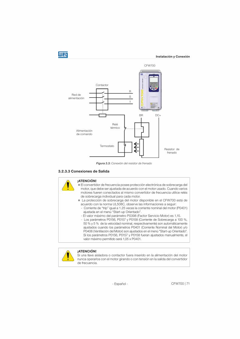
CFW700 | 71
Instalación y Conexión
- Español -
Red de
alimentación
Termostato
Resistor de
frenado
Relé
térmicoAlimentación
de comando
Contactor
CFW700
BR DC+
R
S
T
Figura 3.3: Conexión del resistor de frenado
3.2.3.3 Conexiones de Salida
¡ATENCIÓN!
El convertidor de frecuencia posee protección electrónica de sobrecarga del
motor, que debe ser ajustada de acuerdo con el motor usado. Cuando varios
motores fueren conectados al mismo convertidor de frecuencia utilice relés
de sobrecarga individual para cada motor.
La protección de sobrecarga del motor disponible en el CFW700 está de
acuerdo con la norma UL508C, observe las informaciones a seguir:
- Corriente de “trip” igual a 1.25 veces la corriente nominal del motor (P0401)
ajustada en el menú “Start-up Orientado”.
- El valor máximo del parámetro P0398 (Factor Servicio Motor) es 1,15.
- Los parámetros P0156, P0157 y P0158 (Corriente de Sobrecarga a 100 %,
50 % y 5 % de la velocidad nominal, respectivamente) son automáticamente
ajustados cuando los parámetros P0401 (Corriente Nominal del Motor) y/o
P0406 (Ventilación del Motor) son ajustados en el menú "Start-up Orientado".
Si los parámetros P0156, P0157 y P0158 fueran ajustados manualmente, el
valor máximo permitido será 1,05 x P0401.
¡ATENCIÓN!
Si una llave aisladora o contactor fuera inserido en la alimentación del motor
nunca operarlos con el motor girando o con tensión en la salida del convertidor
de frecuencia.

72 | CFW700
Instalación y Conexión
- Español -
Las características del cable utilizado para la conexión del convertidor de frecuencia al
motor, bien como la suya interconexión y ubicación física, son de extrema importancia para
se evitar la interferencia electromagnética en otros dispositivos, además de afectar la vida
útil del aislamiento de las bobinas y de los rodamientos de los motores accionados por los
convertidores de frecuencia.
Mantenga los cables del motor separado de los demás cables (cables de señal, cables de
sensores, cables de comando, etc.), conforme ítem 3.2.6 - Distancia para Separación de Cables.
Conecte un cuarto cable entre el punto de tierra del motor y el punto de tierra del convertidor.
Cuando fuera utilizado cable blindado para conexión del motor:
Seguir recomendaciones de la norma IEC60034-25.
Utilizar conexión de baja impedancia para altas frecuencias para conectar el blindaje del cable
al punto de tierra. Utilizar piezas suministradas con el convertidor. Consulte el próximo ítem.
Para los tamaños A, B y C existe un accesorio chamado “Kit para blindaje de los cables de
potencia PCSx-01” (consulte ítem 7.2 - Accesorios), el cual puede montarse en la parte inferior del
gabinete – la figura 3.4 muestra un ejemplo. El kit de blindaje de los cables de potencia PCSx-01
acompaña los convertidores con la opción de filtro RFI interno (CFW700...C3...). En el caso de los
tamaños D y E la puesta a tierra del blindaje del cable del motor ya está prevista en el gabinete
estándar del convertidor. Esto también está previsto en los accesorios “Kits Nema1 (KN1x-01)”
de los tamaños A, B y C.
Figura 3.4: Detalle de la conexión del blindaje de los cables del motor con accesorio PCSx-01
3.2.4 Conexiones de Puesta a Tierra
¡PELIGRO!
El convertidor de frecuencia debe ser obligatoriamente puesto a una tierra de
protección (PE).
Utilizar cableado de puesta a tierra con calibre mínimo, igual al indicado en la tabla B.1 y B.2.
Conecte los puntos de puesta a tierra del convertidor a una barra de puesta a
tierra específica, o al punto de tierra específica o todavía al punto de tierra general
(resistencia ≤ 10 Ω).
El conductor neutro de la red que alimenta el convertidor de frecuencia debe ser
aislado del sistema de puesta a tierra, sin embargo el mismo no debe ser utilizado
para hacer la puesta a tierra del convertidor.
Para compatibilidad con la norma IEC61800-5-1 utilice como mínimo un cable
de cobre de 10 mm2 o 2 cables con el mismo calibre del cable de puesta a tierra
especificado en las tablas B.1 y B.2 para conexión del convertidor al tierra de
protección, ya que la corriente de fuga es mayor que 3,5 mAca.
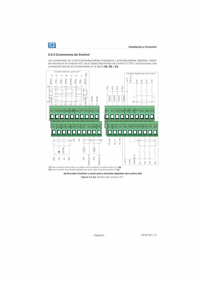
CFW700 | 73
Instalación y Conexión
- Español -
3.2.5 Conexiones de Control
Las conexiones de control (entradas/salidas analógicas y entradas/salidas digitales), deben
ser hechas en el conector XC1 de la Tarjeta Electrónica de Control CC700. Las funciones y las
conexiones típicas son presentadas en la figura (a), (b) y (c).
GN
D (24
V)
Bla
nco
RE
F+
AI1
+
AI1
-
RE
F-
AO
1
AO
2
AG
ND
(24 V
)
AG
ND
(24 V
)
AI2
+
AI2
-
rpm
am
p
+V A A B B Z Z GN
D
Azu
l
Ro
jo
Verd
e
Am
arillo
Ro
sa
Gris
ZZBBAA+5 V
-EN
C
Marr
ón
B -
RS
48
5
>3
00
Ω
DO
2
DO
3
DO
4
DO
5
+24
V+
24
V
CO
M
GN
D (24
V)
RL1-N
A
RL1-C
RL1-N
F
DI5
DI1
DI6
DI2
DI7
DI3
DI8
DI4
>3
00
Ω
>3
00
Ω
>3
00
Ω
Encoder linedrive o push-pull (1)
A -
RS
48
5
GN
D-E
NC
≥5
kΩ
Entradas digitales tipo activo alto (2)
(1) Para conexión de encoder con salida colector abierto consulte la figura 3.5 (b).
(2) Para conexión de entradas digitales tipo activo bajo consulte la figura 3.5 (c).
(a) Encoder linedrive o push-pull y entradas digitales tipo activo alto
Figura 3.5 (a): Señales del conector XC1

74 | CFW700
Instalación y Conexión
- Español -
+24
V
GN
D (24 V
)
DI5
DI6
DI7
DI8
Entradas digitales tipo activo bajo
+24
V
CO
M
GN
D (24
V)
DI1
DI2
DI3
DI4
(c) Entradas digitales tipo activo bajo
Encoder colector abierto
ZZZ
BBB
AAA
+V
(5 V
)+
5 V
-EN
C
GN
D-E
NC
CO
M
(b) Encoder con salida colector
abierto
Figura 3.5 (b) y (c) (cont.): Señales del conector XC1
Señal
Tiempo
A
B
A
B
Figura 3.6: Fase estándar de las señales del encoder
Consulte la figura A.3 para visualizar la localización de la tarjeta de control, del conector XC1
(señales de control), de las DIP-switches S1 (para selección del tipo de señal de las entradas
y salidas analógicas) y S2 (terminación de la red RS485) y de los slots 3 y 5 para accesorios
(consulte el ítem 7.2 - Accesorios).

CFW700 | 75
Instalación y Conexión
- Español -
Los convertidores CFW700 son suministrados con las entradas digitales configuradas como
activo alto y las entradas y salidas analógicas configuradas para señal en tensión 0...10 V.
¡NOTA!
Para utilizar las entradas y/o salidas analógicas con señal en corriente, ajustar
la lave S1 y los parámetros relacionados conforme tabla 3.1. Para configurar
entradas analógicas para señal en tensión -10...10 V ajustar parámetros P0233
y P0238 conforme tabla 3.1. Para más informaciones consulte el manual de
programación y mantenimiento del CFW700.
Tabla 3.1: Configuraciones de los selectores del tipo de señal en las entradas y salidas analógicas
Entrada/
SalidaSeñal
Ajuste de
S1
Rango de la
señal Ajuste de parámetros
AI1
Tensión S1.2 = OFF (*) 0…10 V (*) P0233 = 0 (referencia directa) o 2 (referencia inversa).
-10…10 V P0233 = 4
Corriente S1.2 = ON0...20 mA P0233 = 0 (referencia directa) o 2 (referencia inversa).
4...20 mA P0233 = 1 (referencia directa) o 3 (referencia inversa).
AI2
Tensión S1.1 = OFF (*) 0…10 V (*) P0238 = 0 (referencia directa) o 2 (referencia inversa).
-10…10 V P0238 = 4
Corriente S1.1 = ON0...20 mA P0238 = 0 (referencia directa) o 2 (referencia inversa).
4...20 mA P0238 = 1 (referencia directa) o 3 (referencia inversa).
AO1
Tensión S1.3 = ON (*) 0...10 V (*) P0253 = 0 (referencia directa) o 2 (referencia inversa).
Corriente S1.3 = OFF0...20 mA P0253 = 0 (referencia directa) o 2 (referencia inversa).
4...20 mA P0253 = 1 (referencia directa) o 3 (referencia inversa).
AO2
Tensión S1.4 = ON (*) 0...10 V (*) P0256 = 0 (referencia directa) o 2 (referencia inversa).
Corriente S1.4 = OFF0...20 mA P0256 = 0 (referencia directa) o 2 (referencia inversa).
4...20 mA P0256 = 1 (referencia directa) o 3 (referencia inversa).
(*) Ajuste de fábrica.
¡NOTA!
Configuraciones para el selector S2:
S2.1 = ON y S2.2 = ON: terminación RS485 conectada.
S2.1 = OFF y S2.2 = OFF: terminación RS485 desconectada.
El estándar de fábrica para el selector S2.1 y S2.2 es igual a OFF.
Otras combinaciones del selector S2 no son permitidas.
Especificaciones técnicas para el encoder y cable del encoder conforme tabla 3.2.
Tabla 3.2: Especificaciones técnicas para encoder y cable del encoder
Características Especificaciones
Encoder
Alimentación 5 V
Canales2 canales en cuadratura (90º) + pulsos de cero con salidas complementares
(diferenciales) o colector-abierto.
SeñalesA, A, B, B, Z y Z
Disponible para 2 canales: A, A, B, B.
Circuito de salida Tipo linedrive, push-pull o colector abierto. Tensión máxima 12 V.
Aislamiento Circuito electrónico aislado de la carcaza del encoder.
Pulsos Número de pulsos por rotación recomendado = 1024 ppr.
Frecuencia Máxima permitida = 100 kHz
Cable del
encoder
Tipo de cable Cable blindado balanceado (para operaciones con señales diferenciales).
ConexiónEl blindaje del cable debe ser conectado a la tierra a través de dispositivos
en la placade blindaje del controle (consulte figura 3.5).
Distancia ≥ 25 cm de los demás cableados.
Aislamiento Usar electroducto metálico.
Longitud Máximo = 10 m.
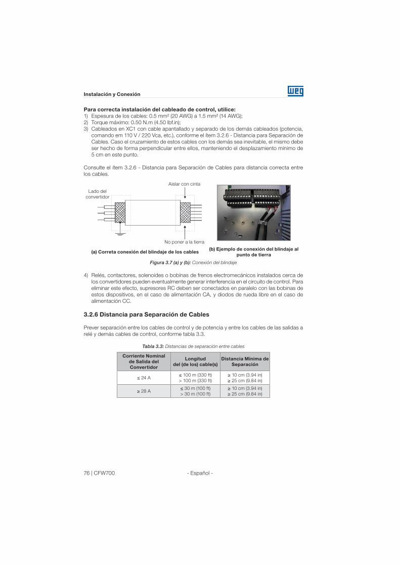
76 | CFW700
Instalación y Conexión
- Español -
Para correcta instalación del cableado de control, utilice:
1) Espesura de los cables: 0.5 mm² (20 AWG) a 1.5 mm² (14 AWG);
2) Torque máximo: 0.50 N.m (4.50 lbf.in);
3) Cableados en XC1 con cable apantallado y separado de los demás cableados (potencia,
comando em 110 V / 220 Vca, etc.), conforme el ítem 3.2.6 - Distancia para Separación de
Cables. Caso el cruzamiento de estos cables con los demás sea inevitable, el mismo debe
ser hecho de forma perpendicular entre ellos, manteniendo el desplazamiento mínimo de
5 cm en este punto.
Consulte el ítem 3.2.6 - Distancia para Separación de Cables para distancia correcta entre
los cables.
No poner a la tierra
Lado del
convertidor
Aislar con cinta
(a) Correta conexión del blindaje de los cables(b) Ejemplo de conexión del blindaje al
punto de tierra
Figura 3.7 (a) y (b): Conexión del blindaje
4) Relés, contactores, solenoides o bobinas de frenos electromecánicos instalados cerca de
los convertidores pueden eventualmente generar interferencia en el circuito de control. Para
eliminar este efecto, supresores RC deben ser conectados en paralelo con las bobinas de
estos dispositivos, en el caso de alimentación CA, y diodos de rueda libre en el caso de
alimentación CC.
3.2.6 Distancia para Separación de Cables
Prever separación entre los cables de control y de potencia y entre los cables de las salidas a
relé y demás cables de control, conforme tabla 3.3.
Tabla 3.3: Distancias de separación entre cables
Corriente Nominal
de Salida del
Convertidor
Longitud
del (de los) cable(s)
Distancia Mínima de
Separación
≤ 24 A≤ 100 m (330 ft)
> 100 m (330 ft)
≥ 10 cm (3.94 in)
≥ 25 cm (9.84 in)
≥ 28 A≤ 30 m (100 ft)
> 30 m (100 ft)
≥ 10 cm (3.94 in)
≥ 25 cm (9.84 in)
CFW700 | 77
Instalación y Conexión
- Español -
3.3 INSTALACIONES DE ACUERDO CON LA DIRECTIVA EUROPEA DE
COMPATIBILIDAD ELECTROMAGNÉTICA
Los convertidores con la opción C3 (CFW700...C3...) poseen filtro RFI interno para reducción
de la interferencia electromagnética. Estos convertidores, cuando correctamente instalados,
atienden los requisitos de la diretiva de compatibilidad electromagnética “EMC Directive 89/336/
EEC” con el complemento 93/68/EEC.
La línea de convertidores CFW700 fue desarrollada apenas para aplicaciones profesionales.
Por esto no se aplican los límites de emisiones de corrientes harmónicas definidas por las
normas EN 61000-3-2 y EN 61000-3-2/A 14.
3.3.1 Instalación Conforme
1) Convertidores con opción filtro RFI interno CFW700...C3...
2) Convertidores del tamaño A a D con tornillos de puesta a tierra de los capacitores de filtro RFI
interno y del tamaño E con cable J1 en la posición (XE1). Para más informaciones consulte
la figura A.6.
3) Cables de salida (cables del motor) apantallados y con el blindaje conectado en los dos
lados, motor y convertidor con conexión de baja impedancia para alta frecuencia. Utilizar
kit PCSx-01 suministrado con los convertidores del tamaño A, B y C. Para modelos de
los tamaños D y E utilizar abrazaderas suministradas con el producto. Garantizar un buen
contacto entre el blindaje del cable y las abrazaderas. Como ejemplo consulte la figura 3.4
y mantenga la separación de los demás cables conforme el ítem 3.2.6 - Distancia para
Separación de Cables.
Longitud máxima del cable del motor y niveles de emisión conducida e irradiada conforme
anexo B.6. Si fuera deseado nivel de emisión inferior y/o mayor longitud de cable del motor,
utilizar filtro RFI externo en la entrada del convertidor. Para más detalles (referencia comercial
del filtro RFI, longitud del cable del motor y niveles de emisión) consulte la tabla B.6.
4) Cables de control blindados y demás cables separados conforme el ítem 3.2.6 - Distancia
para Separación de Cable.
5) Puesta a tierra del convertidor de frecuencia conforme instrucciones del item 3.2.4 -
Conexiones de Puesta a Tierra.
6) Red de alimentación con puesta a tierra.

78 | CFW700
Instalación y Conexión
- Español -
3.3.2 Niveles de Emisión y Inmunidad Cumplidos
Tabla 3.4: Niveles de emisión y inmunidad cumplidos
Fenómeno de EMC Normativa Nivel
Emisión:
Emisión Conducida (“Mains Terminal
Disturbance Voltage”
Rango de Frecuencia: 150 kHz a 30 MHz)IEC/EN61800-3
Depende del modelo del convertidor y de
la longitud del cable del motor. Consulte
la tabla B.6.Emisión Radiada (“Electromagnetic
Radiation Disturbance”
Rango de Frecuencia: 30 MHz a 1000 MHz)
Inmunidad:
Descarga Electrostática (ESD) IEC 61000-4-24 kV descarga por contacto y 8 kV
descarga por el aire.
Transitorios Rápidos (“Fast Transient-Burst”) IEC 61000-4-4
2 kV / 5 kHz (acoplador capacitivo) cables
de entrada;
1 kV / 5 kHz cables de control y de la
HMI remota;
2 kV / 5 kHz (acoplador capacitivo) cable
del motor.
Inmunidad Conducida
(“Conducted Radio-Frequency Common
Mode”)
IEC 61000-4-6
0.15 to 80 MHz; 10 V; 80 % AM (1 kHz).
Cables del motor, de control y de la HMI
remota.
Surtos IEC 61000-4-5
1.2/50 μs, 8/20 μs;
1 kV acoplamiento línea línea;
2 kV acoplamiento línea tierra.
Campo Electromagnético de Radiofrecuencia IEC 61000-4-3
80 a 1000 MHz;
10 V/m;
80 % AM (1 kHz).
Consulte la tabla B.6 para niveles de emisión conducida e irradiada atendidos con o sin filtro
RFI externo. También es presentada la referencia comercial del filtro externo para cada modelo.
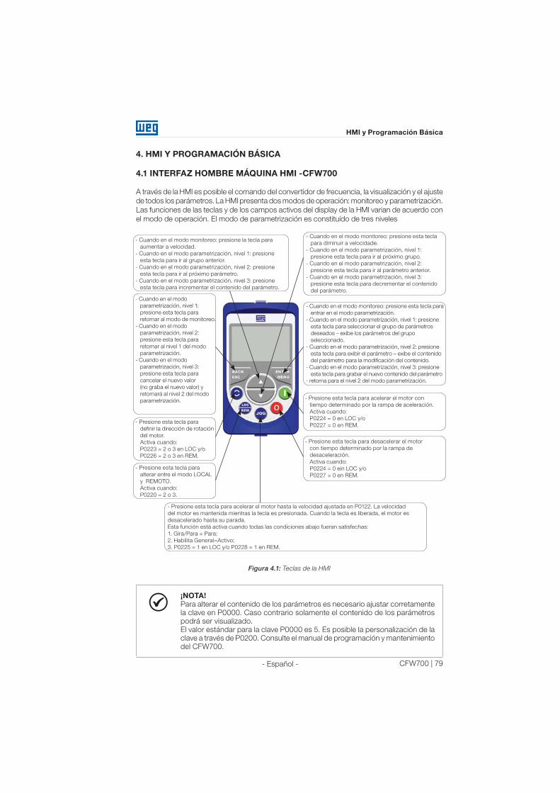
CFW700 | 79
HMI y Programación Básica
- Español -
4. HMI Y PROGRAMACIÓN BÁSICA
4.1 INTERFAZ HOMBRE MÁQUINA HMI -CFW700
A través de la HMI es posible el comando del convertidor de frecuencia, la visualización y el ajuste
de todos los parámetros. La HMI presenta dos modos de operación: monitoreo y parametrización.
Las funciones de las teclas y de los campos activos del display de la HMI varian de acuerdo con
el modo de operación. El modo de parametrización es constituído de tres niveles
- Presione esta tecla para acelerar el motor hasta la velocidad ajustada en P0122. La velocidad
del motor es mantenida mientras la tecla es presionada. Cuando la tecla es liberada, el motor es
desacelerado hasta su parada.
Esta función está activa cuando todas las condiciones abajo fueran satisfechas:
1. Gira/Para = Para;
2. Habilita General=Activo;
3. P0225 = 1 en LOC y/o P0228 = 1 en REM.
- Cuando en el modo monitoreo: presione esta tecla
para diminuir a velocidade.
- Cuando en el modo parametrización, nivel 1:
presione esta tecla para ir al próximo grupo.
- Cuando en el modo parametrización, nivel 2:
presione esta tecla para ir al parámetro anterior.
- Cuando en el modo parametrización, nivel 3:
presione esta tecla para decrementar el contenido
del parámetro.
- Cuando en el modo monitoreo: presione esta tecla para
entrar en el modo parametrización.
- Cuando en el modo parametrización, nivel 1: presione
esta tecla para seleccionar el grupo de parámetros
deseados – exibe los parámetros del grupo
seleccionado.
- Cuando en el modo parametrización, nivel 2: presione
esta tecla para exibir el parámetro – exibe el contenido
del parámetro para la modificación del contenido.
- Cuando en el modo parametrización, nivel 3: presione
esta tecla para grabar el nuevo contenido del parámetro
- retorna para el nivel 2 del modo parametrización.
- Presione esta tecla para acelerar el motor con
tiempo determinado por la rampa de aceleración.
Activa cuando:
P0224 = 0 en LOC y/o
P0227 = 0 en REM.
- Presione esta tecla para desacelerar el motor
con tiempo determinado por la rampa de
desaceleración.
Activa cuando:
P0224 = 0 ein LOC y/o
P0227 = 0 en REM.
- Cuando en el modo monitoreo: presione la tecla para
aumentar a velocidad.
- Cuando en el modo parametrización, nivel 1: presione
esta tecla para ir al grupo anterior.
- Cuando en el modo parametrización, nivel 2: presione
esta tecla para ir al próximo parámetro.
- Cuando en el modo parametrización, nivel 3: presione
esta tecla para incrementar el contenido del parámetro.
- Cuando en el modo
parametrización, nivel 1:
presione esta tecla para
retornar al modo de monitoreo.
- Cuando en el modo
parametrización, nivel 2:
presione esta tecla para
retornar al nivel 1 del modo
parametrización.
- Cuando en el modo
parametrización, nivel 3:
presione esta tecla para
cancelar el nuevo valor
(no graba el nuevo valor) y
retornará al nivel 2 del modo
parametrización.
- Presione esta tecla para
definir la dirección de rotación
del motor.
Activa cuando:
P0223 = 2 o 3 en LOC y/o
P0226 = 2 o 3 en REM.
- Presione esta tecla para
alterar entre el modo LOCAL
y REMOTO.
Activa cuando:
P0220 = 2 o 3.
Figura 4.1: Teclas de la HMI
¡NOTA!
Para alterar el contenido de los parámetros es necesario ajustar corretamente
la clave en P0000. Caso contrario solamente el contenido de los parámetros
podrá ser visualizado.
El valor estándar para la clave P0000 es 5. Es posible la personalización de la
clave a través de P0200. Consulte el manual de programación y mantenimiento
del CFW700.

80 | CFW700
HMI y Programación Básica
- Español -
Display secundario
Unidad de medida
(referida al valor
del display
principal)
Barra gráfica para
monitoreo
de variable
Menú (para selección
de los grupos de
parámetros) –
solamente un grupo
de parámetros es
mostrado cada vez.
Display principal
Status del
convertidor
Local/Remoto
(fuente de comandos
y referencias)Sentido
de giro
Figura 4.2: Áreas del display
Grupos de parámetros disponibles en el campo Menú:
PARAM: todos los parámetros;
READ: solamente los parámetros de lectura;
MODIF: solamente parámetros alterados en relación al estándar de fábrica;
BASIC: parámetros para aplicación básica;
MOTOR: parámetros relacionados al control y datos del motor;
I/O: parámetros relacionados a las entradas/salidas digitales y analógicas;
NET: parámetros relacionados a las redes de comunicación;
HMI: parámetros para configuración de la HMI;
SPLC: parámetros relacionados a la función SoftPLC;
STARTUP: parámetros para Start-up orientado.
Status del convertidor:
LOC: fuente de comandos o referencias local;
REM: fuente de comandos o referencias remoto;
: sentido de giro conforme las flechas;
CONF: configuración;
SUB: subtensión;
RUN: convertidor habilitado y/o frenado CC activo.

CFW700 | 81
HMI y Programación Básica
- Español -
Modo Monitoreo
Es el estado inicial de la HMI luego de la energización y de la pantalla
de inicialización, con valores estándar de fábrica;
El campo Menú no está activo en este modo;
Los campos mostrador principal, mostrador secundario de la HMI y la
barra para monitoreo indican los valores de tres parámetros predefinidos
por P0205, P0206 y P0207.
Partiendo del modo de monitoreo, al presionar la tecla ENTER/MENÚ
se conmuta para el modo parametrización.
Modo Parametrización
Nivel 1:
Este es el primer nivel del modo parametrización. Es posible elegir el
grupo de parámetros utilizando las teclas y .
Los campos mostrador principal, mostrador secundario, barra para
monitoreo de variables y unidades de medida no son mostrados en
este nivel.
Presione la tecla ENTER/MENÚ para ir al nivel 2 del modo parametrización
– selección de los parámetros.
Presione la tecla BACK/ESC para retornar al modo monitoreo.
Nivel 2:
El número del parámetro es exhibido en el mostrador principal y el seu
contenido en el mostrador secundario.
Use las teclas y para encontrar el parámetro deseado.
Presione la tecla ENTER/MENÚ para ir al nivel 3 del modo parametrización
– alteración del contenido de los parámetros.
Presione la tecla BACK/ESC para retornar al nivel 1 del modo
parametrización.
Nivel 3:
El contenido del parámetro es exhibido en el mostrador principal y el
número del parámetro en el mostrador secundario.
Use las teclas y para configurar el nuevo valor para el parámetro
seleccionado.
Presione la tecla ENTER/MENÚ para confirmar la modificación (grabar
el nuevo valor) o BACK/ESC para cancelar la modificación (no graba
el nuevo valor). En ambos los casos la HMI retorna para el nivel 2 del
modo parametrización.
Figura 4.3: Modos de operación de la HMI
La HMI puede ser instalada o retirada del convertidor de frecuencia con el mismo energizado
o desenergizado.
El HMI suministrado con el producto puede también ser utilizado para comando remoto del
convertidor de frecuencia. En ese caso, utilizar cable con conectores D-Sub9 (DB-9) macho
y hembra con conexiones punto a punto (tipo extensor del ratón) o Null-Modem padrón
de mercado. Longitud máxima 10 m. Se recomienda el uso de los espaciadores M3x5.8
suministrados en conjunto con el producto. Torque (Par) de aprieto recomendado: 0.5 N.m
(4.50 Ibf.in).
Para montaje de la HMI en la puerta del tablero o mesa de comando utilizar el accesorio
moldura para HMI (consulte el ítem 7.2 - Accesorios o ejecute orificio conforme la figura A.5).

82 | CFW700
HMI y Programación Básica
- Español -
¡NOTA!
Una lista de los parámetros es suministrada con el producto, para informaciones
adicionales a respecto cada parámetro consulte el manual de programación
y mantenimiento del CFW700 suministrado en formato electrónico en el CD-
ROM que acompaña el producto o puede obtenerse en el sitio de WEG - www.
weg.net.
4.2 APLICATIVOS
El CFW700 posee algumas funcionalidades que permitem adecuar mejor los comandos del
convertidor a la aplicación en sí. Estas funcionalidades fueron agrupadas en un conjunto de
aplicativos, desde los más sencillos, como por ejemplo, comando de avance y retorno, o hasta
los más elaborados, como un regulador PID.
El parámetro P1003 permite seleccionar un aplicativo y cargarlo para el CFW700. Los siguientes
aplicativos están disponibles en el CFW700:
Regulador PID (P1003 = 1);
Potenciómetro Electrónico (PE) (P1003 = 2);
Multispeed (P1003 = 3);
Comando a Tres Cables (Start/Stop) (P1003 = 4);
Comando Avance y Retorno (P1003 = 5).
A seguir es presentada una breve descrición de cada aplicativo y los parámetros relacionados.
Las siglas RO y CFG significam Parámetro Solamente Lectura y Parámetro de Configuración,
respectivamente. Para más informaciones consulte el manual de programación y mantenimiento
del CFW700.
4.2.1 Aplicativo Regulador PID (P1003 = 1)
Este aplicativo puede ser utilizado para controlar un proceso en lazo cerrado. Esta aplicación
coloca un regulador proporcional, integral y derivativo sobrepuesto al control normal de
velocidad del CFW700. El control de proceso es hecho a través de la variación de la velocidad
del motor, manteniendo el valor de la variable del proceso (aquella que se desea controlar) en
el valor deseado.
Para el funcionamento del aplicativo Regulador PID es necesario programar el parámetro
P0221 o P0222 (Selección Referencia local o remota) en 7 = SoftPLC. Funciones definidas
para este aplicativo:
Parámetro P0231 o P0236 (Función del Señal AI1 o AI2):
- Función 1 de la Aplicación representa el valor del Setpoint del PID;
- Función 2 de la Aplicación representa el valor de la Realimentación del PID.
Parámetro P0251 o P0254 (Función de la Salida AO1 o AO2):
- Función 1 de la Aplicación representa el valor del Setpoint del PID;
- Función 2 de la Aplicación representa el valor de la Realimentación del PID.
Parámetro P0263 a P0270 (Función de la Entrada DI1 a DI8):
- Función 1 de la Aplicación representa el comando Manual / Automático.
Parámetro P0275 a P0279 (Función Salida DO1 a DO5):
- Función 1 de la Aplicación representa la condición VP > VPx;
- Función 2 de la Aplicación representa la condición VP < VPy.
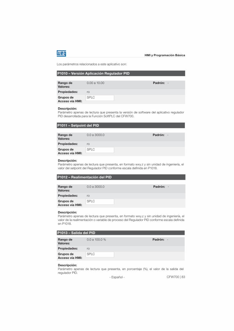
CFW700 | 83
HMI y Programación Básica
- Español -
Los parámetros relacionados a este aplicativo son:
P1010 – Versión Aplicación Regulador PID
Rango de
Valores:
0.00 a 10.00 Padrón: -
Propiedades: ro
Grupos de
Acceso vía HMI:
SPLC
Descripción:
Parámetro apenas de lectura que presenta la versión de software del aplicativo regulador
PID desarrollada para la Función SoftPLC del CFW700.
P1011 – Setpoint del PID
Rango de
Valores:
0.0 a 3000.0 Padrón: -
Propiedades: ro
Grupos de
Acceso vía HMI:
SPLC
Descripción:
Parámetro apenas de lectura que presenta, en formato wxy.z y sin unidad de ingeniería, el
valor del setpoint del Regulador PID conforme escala definida en P1018.
P1012 – Realimentación del PID
Rango de
Valores:
0.0 a 3000.0 Padrón: -
Propiedades: ro
Grupos de
Acceso vía HMI:
SPLC
Descripción:
Parámetro apenas de lectura que presenta, en formato wxy.z y sin unidad de ingeniería, el
valor de la realimentación o variable de proceso del Regulador PID conforme escala definida
en P1018.
P1013 – Salida del PID
Rango de
Valores:
0.0 a 100.0 % Padrón: -
Propiedades: ro
Grupos de
Acceso vía HMI:
SPLC
Descripción:
Parámetro apenas de lectura que presenta, en porcentaje (%), el valor de la salida del
regulador PID.

84 | CFW700
HMI y Programación Básica
- Español -
P1016 – Selección del Setpoint del PID
Rango de
Valores:
0 = HMI
1 = AIx
2 = Serial/USB
3 = CO/DN/DP
Padrón: 0
Propiedades: ro
Grupos de
Acceso vía HMI:
SPLC
Descripción:
Define la fuente de origen del setpoint del regulador PID.
Observaciones:
“HMI” significa que el setpoint del regulador PID será el valor del parámetro P1025;
“AI” significa que el setpoint del regulador PID será proveniente de una entrada analógica,
siendo necesario programar el parámetro P0231 (para AI1) o P0236 (para AI2) en 5=Función
1 de la Aplicación para que la misma sea habilitada al funcionamiento. Caso no sea, será
generado el mensaje de alarma “A770: Programar AI1 o AI2 para Función 1 de la Aplicación”;
“Serie/USB” significa que el setpoint del regulador PID será el valor del parámetro P0683
referenciado al valor porcentual con un decimal, o sea, 100,0 % equivale al valor 1000 en
P0683;
“CO/DN/DP” significa que el setpoint del regulador PID será el valor del parámetro P0685
referenciado al valor porcentual con un decimal, o sea, 100,0 % equivale al valor 1000 en
P0685.
P1018 – Escala de la Realimentación del PID
Rango de
Valores:
0.0 a 3000.0 Padrón: 100.0
Propiedades: -
Grupos de
Acceso vía HMI:
SPLC
Descripción:
Define como será presentada la Realimentación o Variable de Proceso del PID en P1012
(como también el Setpoint del PID en P1011), o sea, el fondo de escala de la realimentación
o variable de proceso del PID que corresponde a 100.0 % en la entrada analógica utilizada
como realimentación del regulador PID.
El formato de la variable siempre será “wxy.z”, o sea, siempre con un decimal.
Ejemplo: El transductor de presión es de 4-20 mA con un rango de 0 a 25 bar; ajuste el
parámetro P1019 en 25.0.

CFW700 | 85
HMI y Programación Básica
- Español -
P1020 – Ganancia Proporcional PID
P1021 – Ganancia Integral PID
P1022 – Ganancia Diferencial PID
Rango de
Valores:
0.000 a 30.000 Padrón: P1020 = 1.000
P1021 = 0.430
P1022 = 0.000
Propiedades: -
Grupos de
Acceso vía HMI:
SPLC
Descripción:
Estos parámetros definen las ganancias de la aplicación regulador PID, y deben ajustarse de
acuerdo con la aplicación que está siendo controlada.
Ejemplos de ajustes iniciales para algunas aplicaciones son presentados en la tabla 19.3.
Tabla 19.3 : Sugerencias para ajustes de las ganancias del regulador PID
Grandeza
Ganancias
Proporcional
P1020
Integral
P1021
Derivativo
P1022
Presión en sistema neumático 1 0.430 0.000
Caudal en sistema neumático 1 0.370 0.000
Presión en sistema hidráulico 1 0.430 0.000
Caudal en sistema hidráulico 1 0.370 0.000
Temperatura 2 0.040 0.000
Nivel 1 Consulte la nota a seguir 1 Consulte la nota a seguir 0.000
¡NOTA!
En el caso del control de nivel, el ajuste de la ganancia integral dependerá del
tiempo que lleva para el reservorio pasar del nivel mínimo aceptable para el
nivel que se desea, en las siguientes condiciones:
1. Para acción directa el tiempo deberá ser medido con el caudal máximo de
entrada y caudal mínimo de salida;
2. Para acción reversa el tiempo deberá ser medido con el caudal mínimo de
entrada y caudal máximo de salida.
Una fórmula para calcular el valor inicial de P1021 en función del tiempo de respuesta del
sistema es presentada a seguir:
P1021=5.00 / t,
Siendo: t=tiempo (en segundos).
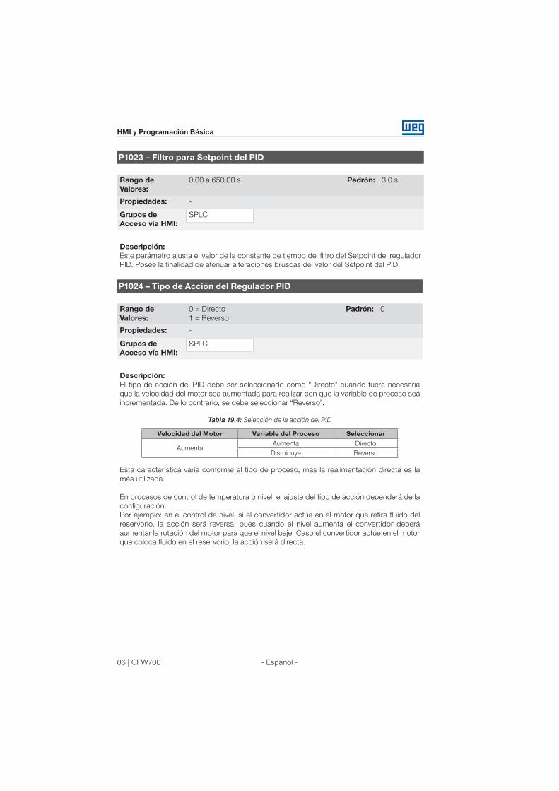
86 | CFW700
HMI y Programación Básica
- Español -
P1023 – Filtro para Setpoint del PID
Rango de
Valores:
0.00 a 650.00 s Padrón: 3.0 s
Propiedades: -
Grupos de
Acceso vía HMI:
SPLC
Descripción:
Este parámetro ajusta el valor de la constante de tiempo del filtro del Setpoint del regulador
PID. Posee la finalidad de atenuar alteraciones bruscas del valor del Setpoint del PID.
P1024 – Tipo de Acción del Regulador PID
Rango de
Valores:
0 = Directo
1 = Reverso
Padrón: 0
Propiedades: -
Grupos de
Acceso vía HMI:
SPLC
Descripción:
El tipo de acción del PID debe ser seleccionado como “Directo” cuando fuera necesaria
que la velocidad del motor sea aumentada para realizar con que la variable de proceso sea
incrementada. De lo contrario, se debe seleccionar “Reverso”.
Tabla 19.4: Selección de la acción del PID
Velocidad del Motor Variable del Proceso Seleccionar
AumentaAumenta Directo
Disminuye Reverso
Esta característica varía conforme el tipo de proceso, mas la realimentación directa es la
más utilizada.
En procesos de control de temperatura o nivel, el ajuste del tipo de acción dependerá de la
configuración.
Por ejemplo: en el control de nivel, si el convertidor actúa en el motor que retira fluido del
reservorio, la acción será reversa, pues cuando el nivel aumenta el convertidor deberá
aumentar la rotación del motor para que el nivel baje. Caso el convertidor actúe en el motor
que coloca fluido en el reservorio, la acción será directa.

CFW700 | 87
HMI y Programación Básica
- Español -
P1025 – Setpoint PID por la HMI
Rango de
Valores:
0.0 a 100.0 % Padrón: 0.0 %
Propiedades: -
Grupos de
Acceso vía HMI:
SPLC
Descripción:
Ese parámetro permite el ajuste del setpoint del Regulador PID a través de las teclas de la
HMI, desde que P1016=0 y se estuviera operando en el modo Automático. Caso la operación
estuviera en modo Manual, la referencia vía HMI es ajustada en el parámetro P0121.
El valor de P1025 es mantenido en el último valor ajustado (backup) mismo deshabilitando o
desenergizando el convertidor (con P1027=1 – Activo).
P1026 – Ajuste Automático del Setpoint del PID por la HMI (P1025)
Rango de
Valores:
0 = Inactivo
1 = Activo
Padrón: 1
Propiedades: CFG
Grupos de
Acceso vía HMI:
SPLC
Descripción:
Cuando el setpoint del regulador PID fuera vía HMI (P1016 = 0) y P1026 estuviera en 1
(activo), al conmutar de manual para automático, el valor en % del setpoint manual que
corresponde a la salida del regulador PID de 0.0 a 100.0 % será cargado en P1025. Con esto
se evitan oscilaciones del PID en la comutación de manual para automático.
P1027 – Backup del Setpoint del PID por la HMI (P1025)
Rango de
Valores:
0 = Inactiva
1 = Activa
Padrón: 1
Propiedades: -
Grupos de
Acceso vía HMI:
SPLC
Descripción:
Este parámetro define si la función de backup del setpoint del PID vía HMI está activa o
inactiva.
Si P1027 = 0 (inactiva), el convertidor no salvará el valor del setpoint del PID cuando fuera
deshabilitado.
Así, cuando el convertidor fuera nuevamente habilitado, el valor del setpoint del PID será
0.0 %.

88 | CFW700
HMI y Programación Básica
- Español -
P1028 – Salida N = 0 PID
Rango de
Valores:
0.0 a 100.0 % Padrón: 0.0 %
Propiedades: -
Grupos de
Acceso vía HMI:
SPLC
Descripción:
El parámetro P1028 actúa en conjunto con el parámetro P0218 (Salida del Bloqueo por
Velocidad Nula), suministrando la condición adicional para la salida del bloqueo. Con esto, es
necesario que el error del PID (la diferença entre el setpoint y la variable de proceso) sea mayor
que el valor programado en P1028 para que el convertidor vuelva a accionar el motor, estado
este conocido por “despertar” (wake up).
P1031 – Valor de la Variable de Proceso X
P1032 – Valor de la Variable de Proceso Y
Rango de
Valores:
0.0 a 100.0 % Padrón: P1031 = 90.0 %
P1032 = 10.0 %
Propiedades: -
Grupos de
Acceso vía HMI:
SPLC
Descripción:
Estos parámetros son usados en las funciones de las salidas digitales con la finalidad de
sinalización/alarma.
4.2.1.1 PID Académico
El regulador PID implementado en el CFW700 es del tipo academico. Se presenta a seguir las
ecuaciones que caracterizan el PID Académico, que es la base del algoritmo de esa función.
La función de transferencia en el dominio de la frecuencia del regulador PID Académico es:
y(s) = Kp x e(s) x [1 + 1 + sTd]
sTi
Substituyéndose el integrador por una sumatoria y la derivada por el cociente incremental, se
obtiene una aproximación para la ecuación de transferencia discreta (recursiva) conforme sigue:
y(k) = y(k-1) + Kp[(1 + Ki.Ta + Kd/Ta).e(k) – (Kd/Ta).e(k-1)]
Siendo:
y(k): salida actual del PID puede variar de 0.0 a 100.0 %;
y(k-1): salida anterior del PID;
Kp (Ganancia proporciona): Kp = P1020;
Ki (Ganancia integral): Ki = P1021 x 100 = [1/Ti x 100];
Kd (Ganancia diferencial): Kd = P1022 x 100 = [Td x 100];
Ta = 0.05 seg (periodo de amostraje del regulador PID);
e(k): error actual [SP*(k) – X(k)];
e(k-1): error anterior [SP*(k-1) – X(k-1)];

CFW700 | 89
HMI y Programación Básica
- Español -
SP*: referencia puede variar de 0.0 a 100.0 %;
X: variable de proceso (o realimentación), leída a través de una de las entradas analógicas (AIx),
puede variar de 0.0 a 100.0 %.
4.2.2 Aplicativo Potenciómetro Electrónico (P.E.) (P1003 = 2)
4.2.2.1 Descripción y Definiciones
El CFW700 dispone de la aplicación POTENCIÓMETRO ELECTRÓNICO, que permite el ajuste
de la referencia de velocidad del motor a través de dos entradas digitales, siendo una para
acelerar y otra para desacelerar el motor.
Con el convertidor habilitado y la entrada digital DIx programada para “Función 1 de la Aplicación
(Acelera)” estando activa, el motor es acelerado de acuerdo con la rampa de aceleración
programada hasta la máxima velocidad definida. Estando apenas la entrada digital DIx
programada para “Función 2 de la Aplicación (Desacelera)” activa, y el convertidor habilitado, la
velocidad del motor desacelera de acuerdo con la rampa de desaceleración programada hasta
la velocidad mínima. Caso ambas las entradas digitales DIx estuvieran activas, por una cuestión
de seguridad, prevalece la función para desacelerar el motor. Con el convertidor deshabilitado,
las entradas digitales DIx son ignoradas a no ser por la condición de ambas activas, caso en
que la referencia de velocidad es ajustada para 0 rpm. La figura a seguir ilustra esta descripción.
Entradas
Digitales
Velocidad
Mínima
de Velocidad
Referencia
Reset para
Cero
Reset
Velocidad
de Salida
Acelera
DesaceleraAceleración
Habilitación
Tiempo
Tiempo
Tiempo
Tiempo
Abierto
24 V
24 V
DIx - Acelera
DIx - Desacelera
DIx - Gira/Para
Desaceleración
Abierto 24 V
Figura 19.5: Funcionamiento de la Aplicación Potenciómetro Electrónico (PE)
Para el funcionamiento de la aplicación potenciómetro electrónico, es necesario programar el
parámetro P0221 ó P0222 en 7=SoftPLC.
Queda definido que:
Función 1 de la Aplicación en los parámetros P0263 a P0270 representa el comando Acelera;
Función 2 de la Aplicación en los parámetros P0263 a P0270 representa el comando
Desacelera.

90 | CFW700
HMI y Programación Básica
- Español -
El comando Acelera es realizado por una de las entradas digitales DI1 a DI8, y debe programarse
en uno de los respectivos parámetros (P0263 a P0270) el valor 20 = Función 1 de la Aplicación.
Caso más de un parámetro fuera programado para esta función, será considerado por la lógica
de funcionamiento solamente el comando de la entrada digital más prioritaria, siendo DI1>DI2
>DI3>DI4>DI5>DI6>DI7>DI8. Caso no sea programada ninguna entrada digital, será generado
el mensaje de alarma “A750: Programar una DI para Función 1 de la Aplicación (Acelera)” y el
funcionamiento de la aplicación no será habilitado.
El comando Desacelera también es realizado por una de las entradas digitales DI1 a DI8, y
debe ser programado en uno de los respectivos parámetros (P0263 a P0270) el valor 21 =
Función 2 de la Aplicación. Caso más de un parámetro fuera programado para esta función,
será considerado por la lógica de funcionamiento solamente el comando de la entrada digital
más prioritaria, siendo DI1>DI2>DI3>DI4>DI5>DI6>DI7>DI8. Caso no sea programada ninguna
entrada digital, será generado el mensaje de alarma “A752: Programar una DI para Función
2 de la Aplicación (Desacelera)” y el funcionamiento de la aplicación no será habilitado.
La entrada Acelera está activa cuando ajustada en 24 V y inactiva en 0 V. Ya la entrada Desacelera
está activa cuando ajustada en 0 V y inactiva en 24 V.
El parámetro P1011 muestra el valor actual de la referencia de velocidad en rpm y sirve
para mantener el valor de la referencia de velocidad cuando no hubiera comando Acelera o
Desacelera.
El parámetro P1012 configura si el backup de la referencia de velocidad será mantenido o irá
para 0 rpm en una nueva habilitación del drive.
4.2.2.2 Colocación en Funcionamiento
Antes de realizar una descripción detallada de los parámetros relacionados a esta aplicación,
presentamos a seguir una rutina paso a paso para la colocación de la aplicación potenciómetro
electrónico en operación.
¡NOTA!
Para que la aplicación potenciómetro electrónico (PE) funcione adecuadamente,
es fundamental verificar si el convertidor está configurado correctamente para
accionar el motor en la velocidad deseada. Para esto, verifique los siguientes
ajustes:
Boosts de torque (P0136 y P0137) y compensación de deslizamiento
(P0138) si estuviera en el modo de control V/f;
Haber ejecutado el autoajuste si estuviera en el modo vectorial;
Rampas de aceleración y desaceleración (P0100 a P0103) y limitación de
corriente (P0135 para controles V/f y VVW ó P0169/P0170 para control
vectorial).
Configurando la aplicación Potenciómetro Electrónico (PE)
1) Seleccionar la aplicación:
Cuando se habilita la aplicación potenciómetro electrónico, realizando P1003=2, el aplicativo
padrón es cargado para el área de la función SoftPLC, disponiendo así, su uso en el CFW700.

CFW700 | 91
HMI y Programación Básica
- Español -
2) Definir entrada digital para el comando Acelera:
Para efectuar el comando Acelera en la aplicación potenciómetro electrónico, es necesario
definir cual entrada digital efectuará este comando; para esto programar uno de los
parámetros P0263 a P0270 en 20=Función 1 de la Aplicación.
Sugerencia: programar P0265 en 20 para que la entrada digital DI3 efectúe el comando
Acelera.
3) Definir entrada digital para el comando Desacelera:
Para efectuar el comando Desacelera en la aplicación potenciómetro electrónico, es
necesario definir cual entrada digital efectuará este comando; para esto programar uno de
los parámetros P0263 a P0270 en 21=Función 2 de la Aplicación.
Sugerencia: programar P0266 en 21 para que la entrada digital DI4 efectúe el comando
Desacelera.
4) Definir la fuente de origen de la Referencia de Velocidad:
Caso la aplicación potenciómetro electrónico deba funcionar cuando CFW700 opera en
modo local, programar P0221 en 7=SoftPLC. Caso la aplicación potenciómetro electrónico
deba funcionar cuando CFW700 opera en modo remoto, programar P0222 en 7=SoftPLC.
5) Configurar el backup de la referencia:
Definir si el valor de la referencia de velocidad será mantenido (P1012=1) o no (P1012=0) en
una nueva energización del convertidor.
6) Límites de Referencia de Velocidad:
Ajustar P0133 y P0134, conforme aplicación.
¡NOTA!
Caso la aplicación potenciómetro electrónico hubiera sido seleccionada
para operar en modo local y la DI1 (P0263) hubiera sido seleccionada para
el comando acelera o desacelera, el convertidor podrá pasar para el estado
"configuración (CONF)", siendo entonces necesario alterar la programación
padrón del parámetro P0227.
Colocando en Operación
Verifique el estado de la aplicación potenciómetro electrónico en el parámetro P1000. Valor
igual a 4 indica que la aplicación potenciómetro electrónico ya está en operación. Valor igual
la 3 indica que la aplicación potenciómetro electrónico está parada, por lo tanto, es necesario
alterar el valor del comando para SoftPLC en el parámetro P1001 para 1 (ejecuta aplicación).
Valores diferentes de 3 ó 4 indican que el aplicativo no podrá entrar en operación.
Para más detalles, consultar el manual de la SoftPLC del CFW700.
4.2.2.3 Parámetros
A seguir están descriptos los parámetros relacionados a la aplicación Potenciómetro Electrónicos
(P.E.) de forma detallada.

92 | CFW700
HMI y Programación Básica
- Español -
P1010 – Versión Aplicación Potenciómetro Electrónico (P.E.)
Rango de
Valores:
0.00 a 10.00 Padrón: -
Propiedades: ro
Grupos de
Acceso vía HMI:
SPLC
Descripción:
Parámetro apenas de lectura que presenta la versión de software del aplicativo potenciómetro
electrónico desarrollada para la Función SoftPLC del CFW700.
P1011 – Referencia de Velocidad P.E.
Rango de
Valores:
0 a 18000 rpm Padrón: -
Propiedades: ro
Grupos de
Acceso vía HMI:
SPLC
Descripción:
Parámetro apenas de lectura que presenta, en rpm, el valor actual de la referencia de
velocidad del potenciómetro electrónico.
P1012 – Backup de la referencia de Velocidad P.E.
Rango de
Valores:
0 = Inactiva
1 = Activa
Padrón: 1
Propiedades: -
Grupos de
Acceso vía HMI:
SPLC
Descripción:
Este parámetro define si la función de backup de la referencia de velocidad del potenciómetro
electrónico está activa o inactiva.
Si P1012=0 (Inactiva), el convertidor no salvará el valor de la referencia de velocidad cuando
fuera deshabilitado. Así, cuando el convertidor fuera nuevamente habilitado, el valor de la
referencia de velocidad asumirá el valor del límite mínimo de velocidad (P0133).
4.2.3 Aplicativo Multispeed
El CFW700 dispone de la aplicación MULTISPEED, que permite el ajuste de la referencia de
velocidad relacionando los valores definidos por los parámetros P1011 a P1018 a través de la
combinación lógica de las entradas digitales DI4, DI5 y DI6, teniendo como límite máximo 8
referencias de velocidad preprogramadas. Trae como ventajas la estabilidad de las referencias
fijas preprogramadas y la inmunidad contra ruidos eléctricos (entradas digitales DIx aisladas).

CFW700 | 93
HMI y Programación Básica
- Español -
La selección de la referencia de velocidad es realizada por la combinación lógica de las entradas
digitales DI4, DI5 y DI6, debiendo programarse los respectivos parámetros (P0266, P0267 y
P0268) para “Función 1 de la Aplicación (Multispeed)”. Caso no sea programado ninguna de
las entradas digitales para la “Función 1 de la Aplicación”, será generado el mensaje de alarma
“A750: Programar una DI para Multispeed” y no será habilitada la escritura de referencia de
velocidad para el convertidor.
Velocidad
de Salida
Rampa de
Aceleración
Tiempo
0 V (Abierto)
0 V (Abierto)
0 V (Abierto)
24 V
24 V
24 V
DI5
DI4
DI6
P1011
P1013
P1014
P1015
P1016
P1017
P1018
P1012
Figura 19.6: Funcionamento da Aplicação Multispeed
Para el funcionamiento de la aplicación multispeed, es necesario programar el parámetro
P0221 ó P0222 en 7=SoftPLC.
Queda definido que:
Función 1 de la Aplicación en los parámetros P0266 a P0268 representa el comando
Multispeed.
La selección de la referencia de velocidad ocurre de acuerdo con la tabla abajo:
Tabla 4.1: Referencia de velocidad Multispeed
DI6 DI5 DI4 Referencia de Velocidad
0 V 0 V 0 V P1011
0 V 0 V 24 V P1012
0 V 24 V 0 V P1013
0 V 24 V 24 V P1014
24 V 0 V 0 V P1015
24 V 0 V 24 V P1016
24 V 24 V 0 V P1017
24 V 24 V 24 V P1018
Caso alguna entrada no estuviera seleccionada para Multispeed, deberá ser considerada
como 0 V.
Los parámetros P1011 a P1018 definen el valor de la referencia de velocidad cuando el Multispeed
está en funcionamiento.
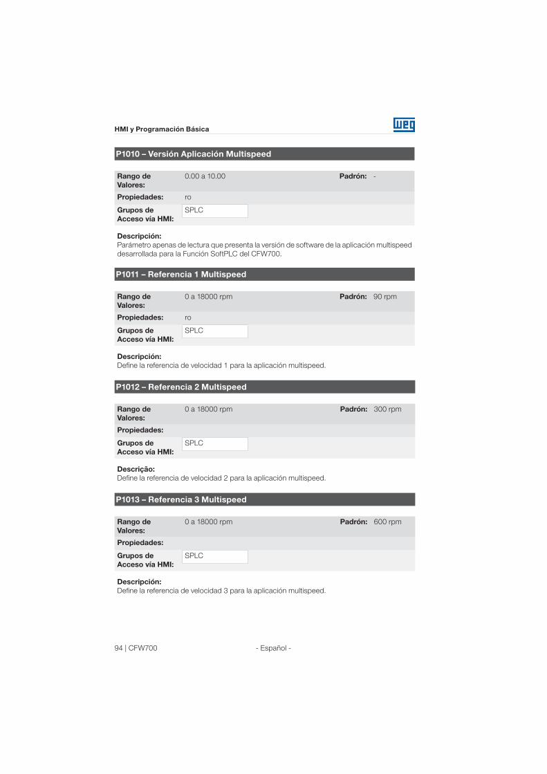
94 | CFW700
HMI y Programación Básica
- Español -
P1010 – Versión Aplicación Multispeed
Rango de
Valores:
0.00 a 10.00 Padrón: -
Propiedades: ro
Grupos de
Acceso vía HMI:
SPLC
Descripción:
Parámetro apenas de lectura que presenta la versión de software de la aplicación multispeed
desarrollada para la Función SoftPLC del CFW700.
P1011 – Referencia 1 Multispeed
Rango de
Valores:
0 a 18000 rpm Padrón: 90 rpm
Propiedades: ro
Grupos de
Acceso vía HMI:
SPLC
Descripción:
Define la referencia de velocidad 1 para la aplicación multispeed.
P1012 – Referencia 2 Multispeed
Rango de
Valores:
0 a 18000 rpm Padrón: 300 rpm
Propiedades:
Grupos de
Acceso vía HMI:
SPLC
Descrição:
Define la referencia de velocidad 2 para la aplicación multispeed.
P1013 – Referencia 3 Multispeed
Rango de
Valores:
0 a 18000 rpm Padrón: 600 rpm
Propiedades:
Grupos de
Acceso vía HMI:
SPLC
Descripción:
Define la referencia de velocidad 3 para la aplicación multispeed.
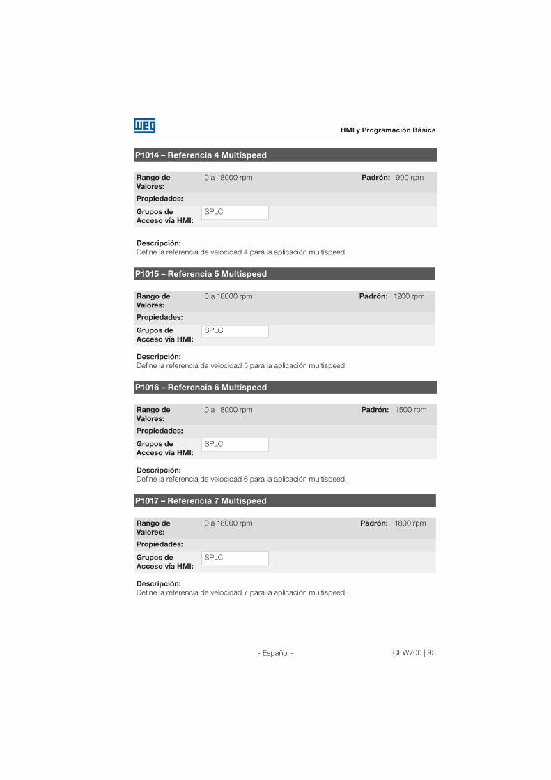
CFW700 | 95
HMI y Programación Básica
- Español -
P1014 – Referencia 4 Multispeed
Rango de
Valores:
0 a 18000 rpm Padrón: 900 rpm
Propiedades:
Grupos de
Acceso vía HMI:
SPLC
Descripción:
Define la referencia de velocidad 4 para la aplicación multispeed.
P1015 – Referencia 5 Multispeed
Rango de
Valores:
0 a 18000 rpm Padrón: 1200 rpm
Propiedades:
Grupos de
Acceso vía HMI:
SPLC
Descripción:
Define la referencia de velocidad 5 para la aplicación multispeed.
P1016 – Referencia 6 Multispeed
Rango de
Valores:
0 a 18000 rpm Padrón: 1500 rpm
Propiedades:
Grupos de
Acceso vía HMI:
SPLC
Descripción:
Define la referencia de velocidad 6 para la aplicación multispeed.
P1017 – Referencia 7 Multispeed
Rango de
Valores:
0 a 18000 rpm Padrón: 1800 rpm
Propiedades:
Grupos de
Acceso vía HMI:
SPLC
Descripción:
Define la referencia de velocidad 7 para la aplicación multispeed.

96 | CFW700
HMI y Programación Básica
- Español -
P1018 – Referencia 7 Multispeed
Rango de
Valores:
0 a 18000 rpm Padrón: 1650 rpm
Propiedades:
Grupos de
Acceso vía HMI:
SPLC
Descripción:
Define la referencia de velocidad 8 para la aplicación multispeed.
4.2.4 Aplicativo Comando a Tres Cables (Start / Stop)
El CFW700 dispone de la aplicación COMANDO A TRES CABLES (START / STOP), que permite
el comando del convertidor de manera análoga a un arranque directo con botón de emergencia
y contacto de retención.
De esta forma, la entrada digital DIx programada para “Función 1 de la Aplicación (Start)”
habilita la rampa el convertidor a través de un único pulso si la entrada digital DIx programada
para “Función 2 de la Aplicación (Stop)” estuviera activa.
El convertidor deshabilita la rampa cuando la entrada digital Desconecta (Stop) es desactivada.
La figura a seguir ilustra esta descripción.
Tiempo
Tiempo
24 V
Velocidad
del motor
24 V
Abierto
AbiertoDIx - Stop
DIx - Start
Tiempo
Figura 4.5: Funcionamiento del aplicativo comando a tres cables (Start / Stop)
Para el funcionamiento de la aplicación comando a tres cables, es necesario programar el
parámetro P0224 ó P0227 en 4=SoftPLC.
Queda definido que:
Función 1 de la Aplicación en los parámetros P0263 a P0270 representa el comando Conecta
(Start);
Función 2 de la Aplicación en los parámetros P0263 a P0270 representa el comando
Desconecta (Stop).
El comando Conecta (Start) es realizado por una de las entradas digitales DI1 a DI8, debiendo
programarse en uno de los respectivos parámetros (P0263 a P0270) el valor 20 = Función
1 de la Aplicación. Caso más de un parámetro fuera programado para esta función, será
considerado por la lógica de funcionamiento solamente el comando de la entrada digital
más prioritaria, siendo DI1>DI2>DI3>DI4>DI5>DI6>DI7>DI8. Caso no sea programada ninguna
entrada digital, será generado el mensaje de alarma “750: Programar una DI para Función 1 de
la Aplicación (Start)” y el funcionamiento de la aplicación no será habilitado.

CFW700 | 97
HMI y Programación Básica
- Español -
El comando Desconecta (Stop) también es realizado por una de las entradas digitales DI1 a
DI8, debiendo programarse en uno de los respectivos parámetros (P0263 a P0270) el valor 21
= Función 2 de la Aplicación. Caso más de un parámetro fuera programado para esta función,
será considerado por la lógica de funcionamiento solamente el comando de la entrada digital
más prioritaria, siendo DI1>DI2>DI3>DI4>DI5>DI6>DI7>DI8. Caso no sea programada ninguna
entrada digital, será generado el mensaje de alarma “A752: Programar una DI para Función 2
de la Aplicación (Stop)” y el funcionamiento de la aplicación no será habilitado.
Tanto la entrada Conecta (Start) cuanto la entrada Desconecta (Stop) serán activadas cuando
en 24 V y inactivadas en 0 V.
Estando el convertidor habilitado en modo local o en modo remoto, sin falla, sin subtensión, sin
alarma A750 y sin alarma A752, es ejecutado el comando “Habilita General” en el convertidor.
Caso hubiera alguna entrada digital programada para la función “Habilita General”, el drive será
efectivamente habilitado cuando las dos fuentes de comando estuvieran activas.
P1010 – Versión Aplicación Comando a Tres Cables (Start / Stop)
Rango de
Valores:
0.00 a 10.00 Padrón: -
Propiedades: ro
Grupos de
Acceso vía HMI:
SPLC
Descripción:
Parámetro apenas de lectura que presenta la versión de software del aplicativo comando a
tres cables desarrollada para la función SoftPLC del CFW700.
4.2.5 Aplicativo Comando Avance y Retorno (P1003 = 5)
El CFW700 dispone de la aplicación COMANDO AVANCE Y RETORNO, que proporciona al
usuario la combinación de dos comandos del convertidor (Sentido de Giro y Gira/Para) en
solamente un comando vía entrada digital.
De esta forma, la entrada digital DIx programada para “Función 1 de la Aplicación (Avance)”
combina el sentido de giro horario con el comando habilita rampa; ya la entrada digital DIx
programada para “Función 2 de la Aplicación (Retorno)” combina sentido de giro antihorario
con el comando habilita rampa. La figura a seguir ilustra esta descripción.

98 | CFW700
HMI y Programación Básica
- Español -
Abierto
Tiempo
24 V
Tiempo
Tiempo
24 V
AbiertoDIx - Retraso
DIx - Avanzo
Velocidad del
motorHorario
Antihorario
Figura 4.6: Funcionamento del aplicativo comando avance y retorno
Para el funcionamiento de la aplicación comando avance y retorno, es necesario programar el
parámetro P0223 en 9=SoftPLC(H) o 10=SoftPLC(AH) en conjunto con el parámetro P0224 en
4=SoftPLC, o entonces, programar el parámetro P0226 en 9=SoftPLC(H) o 10=SoftPLC(AH)
en conjunto con el parámetro P0227 en 4=SoftPLC.
Caso no sea programada la Selección Giro Local (P0223), será generado el mensaje de alarma
“A760: Programar Giro Local para SoftPLC” y el funcionamiento de la aplicación no será
habilitado caso la Selección Gira/Para Local (P0224) hubiera sido programada para SoftPLC. El
mismo se aplica para la Selección Giro Remoto (P0226), siendo generado el mensaje de alarma
“A762: Programar Giro Remoto para SoftPLC” y el funcionamiento de la aplicación no será
habilitado caso la Selección Gira/Para Remoto (P0227) hubiera sido programada para SoftPLC.
Queda definido que:
Función 1 de la Aplicación en los parámetros P0263 a P0270 representa el comando Avance;
Función 2 de la Aplicación en los parámetros P0263 a P0270 representa el comando Retorno.
El comando Avance es realizado por una de las entradas digitales DI1 a DI8, debiendo ser
programado en uno de los respectivos parámetros (P0263 a P0270) el valor 20 = Función
1 de la Aplicación. Caso más de un parámetro fuera programado para esta función, será
considerado por la lógica de funcionamiento solamente el comando de la entrada digital más
prioritaria, siendo DI1>DI2>DI3>DI4>DI5>DI6>DI7>DI8. Caso no sea programada ninguna
entrada digital, será generado el mensaje de alarma “A750: Programar una DI para Función
1 de la Aplicación (Avance)” y el funcionamiento de la aplicación no será habilitado. Queda
definido que el sentido de giro para el comando Avance será siempre “Horario”.
El comando Retorno también es realizado por una de las entradas digitales DI1 a DI8, debiendo
ser programado en uno de los respectivos parámetros (P0263 a P0270) el valor 21 = Función
2 de la Aplicación. Caso más de un parámetro fuera programado para esta función, será
considerado por la lógica de funcionamiento solamente el comando de la entrada digital
más prioritaria, siendo DI1>DI2>DI3>DI4>DI5>DI6>DI7>DI8. Caso no sea programada ninguna
entrada digital, será generado el mensaje de alarma “A752: Programar una DI para Función 2 de
la Aplicación (Retorno)” y el funcionamiento de la aplicación no será habilitado. Queda definido
que el sentido de giro para el comando Retorno será siempre “Antihorario”.

CFW700 | 99
HMI y Programación Básica
- Español -
Tanto la entrada Avance cuanto la entrada Retorno son activas cuando estuvieran en 24 V y
inactivas en 0 V.
Estando el convertidor habilitado en modo local o en modo remoto, sin falla, sin subtensión, sin
alarma A750, sin alarma A752, sin alarma A760 y sin alarma A762, es ejecutado el comando
“Habilita General” en el convertidor.
Caso hubiera alguna entrada digital programada para la función “Habilita General”, el drive será
efectivamente habilitado cuando las dos fuentes de comando estuvieran activas.
Con la entrada digital Avance activa y la entrada digital Retorno inactiva, es ejecutado el comando
sentido de giro horario y habilita rampa. Caso la entrada digital Retorno quedara activa, nada es
alterado en el funcionamiento del convertidor. Cuando los dos comandos estuvieran inactivos,
el comando habilita rampa es retirado y el motor será desacelerado hasta 0 rpm. Ya con la
entrada digital Retorno activa y la entrada digital Avance inactiva, es ejecutado el comando
sentido de giro antihorario y habilita rampa. Caso la entrada digital Avance quede activa, nada
es alterado en el funcionamiento del convertidor. Cuando los dos comando estuvieran inactivas,
el comando habilita rampa es retirado y el drive será desacelerado hasta 0 rpm. Caso ambas
entradas digitales para Avance y Retorno sean activas al mismo tiempo, será generado el
comando Avance.
P1010 – Versión Aplicación Comando Avance y Retorno
Rango de
Valores:
0.00 a 10.00 Padrón: -
Propiedades: ro
Grupos de
Acceso vía HMI:
SPLC
Descripción:
Parámetro apenas de lectura que presenta la versión de software del aplicativo comando
avance y retorno desarrollada para la Función SoftPLC del CFW700.

100 | CFW700
Energización y Puesta en Marcha
- Español -
5. ENERGIZACIÓN Y PUESTA EN MARCHA
5.1 PREPARACIÓN Y ENERGIZACIÓN
El convertidor ya debe estar sido instalado de acuerdo con el Capítulo 3 – Instalación y Conexión.
¡PELIGRO!
Siempre desconecte la alimentación general antes de efectuar cualesquiera
conexiones.
1) Verificar si las conexiones de potencia, de puesta a tierra y de control están correctas y bien
fijadas.
2) Retire todos los materiales excedentes del interior del convertidor o accionamiento.
3) Verifique las conexiones del motor y si la corriente y tensión del motor están de acuerdo
con el del convertidor de frecuencia.
4) Desacople mecánicamente el motor de la carga:
Si el motor no puede ser desacoplado, tenga la certeza de que el giro en cualquier dirección
(Horario u Antihorario) no causará daños a la máquina o riesgo de accidentes.
5) Cierre las tapas del convertidor de frecuencia o accionamiento.
6) Haga la medición de la tensión de la red y verifique si esta dentro del rango permitido,
conforme presentado en el capítulo 8 (Especificaciones Técnicas).
7) Alimente la entrada:
Cierre la seccionadora de entrada.
8) Verifique el suceso de la energización:
El display debe presentar en la pantalla el modo monitoreo y el LED de estado debe enceder
y permanecer encendido con color verde.
5.2 PUESTA EN MARCHA
La puesta en marcha en el modo V/f es explicada de modo simples en 3 pasos, usando las
facilidades de programación con los grupos de parámetros existentes. STARTUP y BASIC.
Secuencia:
(1) Ajuste de la contraseña para modificación de parámetros.
(2) Ejecución de la rutina de Start-up Orientado (grupo STARTUP).
(3) Ajuste de los parámetros del grupo Aplicación Básica (BASIC).

CFW700 | 101
Energización y Puesta en Marcha
- Español -
5.2.1 Menú STARTUP - Start-up Orientado
Sec. Acción/ Indicación en el display Sec. Acción/ Indicación en el display
15
Modo Monitoreo.
Presione la tecla ENTER/MENÚ
para entrar en el 1° nivel del modo
programación.
Altere el contenido del parámetro P0317
para “1 – Sí”, usando la tecla .
2 6
El grupo PARAM está seleccionado,
presione las teclas o hasta
seleccionar el grupo STARTUP.
Cuando alcanzara el valor deseado,
presione ENTER/MENÚ para grabar
la alteración.
3 7Cuando seleccionado el grupo presione
ENTER/MENÚ.
Se inicia la rutina del Start-up Orientado.
El estado CONF es indicado en la HMI.
El parámetro “P0000 – Acceso a los
parámetros” está seleccionado. Altere
el valor de la clave para configurar los
demás parámetros, caso no estuviera
alterado. El valor estándar de fábrica
es 5.
Presione la tecla para el próximo
parámetro.
4 8
E l pa r á m e t ro “ P 0 317 – S t a r t-
up Orientado” está seleccionado,
presione ENTER/MENÚ para acceder
al contenido del parámetro.
Si necesario altere el contenido de
“P0296 – Tensión Nominal Red”. Esta
alteración afectará P0151, P0153,
P0185, P0321, P0322, P0323 y P0400.
Presione la tecla para el próximo
parámetro.
Figura 5.1: Secuencia del grupo Start-up Orientado
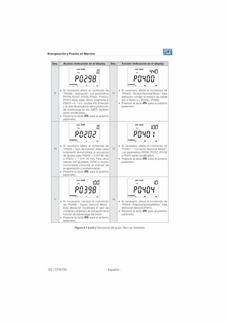
102 | CFW700
Energización y Puesta en Marcha
- Español -
Sec. Acción/ Indicación en el display Sec. Acción/ Indicación en el display
9 12Si necesario altere el contenido de
“P0298 – Aplicación”. Los parámetros
P0156, P0157, P0158, P0401, P0404 y
P0410 serán (este último solamente si
P0202 = 0, 1 o 2 -modos V/f). El tiempo
y el nivel de actuación de la protección
de sobrecarga en los IGBTs también
serán modificados.
Presione la tecla para el próximo
parámetro.
Si necesario altere el contenido de
“P0400 – Tensión Nominal Motor”. Esta
alteración corrige la tensión de salida
por el factor x = P0400 / P0296.
Presione la tecla para el próximo
parámetro.
10 13Si necesario altere el contenido de
“P0202 – Tipo de Control”. Esta rutina
solamente demonstrará la secuencia
de ajustes para P0202 = 0 (V/f 60 Hz)
o P0202 = 1 (V/f 50 Hz). Para otros
valores (V/f ajustable, VVW o modos
vectoriales) consulte el manual de
programación y mantenimiento.
Presione la tecla para el próximo
parámetro.
Si necesario altere el contenido de
“P0401 – Corriente Nominal Motor”.
Los parámetros P0156, P0157, P0158
y P0410 serán modificados.
Presione la tecla para el próximo
parámetro.
11 14Si necesario cambie el contenido
de “P0398 – Factor Servicio Motor”.
Esta alteración modificará el valor de
corriente y el tiempo de actuación de la
función de sobrecarga del motor.
Presione la tecla para el próximo
parámetro.
Si necesario altere el contenido de
“P0404 – Potencia Nominal Motor”. Esta
alteración afectará P0410.
Presione la tecla para el próximo
parámetro.
Figura 5.1 (cont.): Secuencia del grupo Start-up Orientado

CFW700 | 103
Energización y Puesta en Marcha
- Español -
Sec. Acción/ Indicación en el display Sec. Acción/ Indicación en el display
15 18Si necesario altere el contenido de
“P0403 – Frecuencia Nominal Motor”.
Esta alteración modifica P0402.
Presione la tecla para el próximo
parámetro.
Si necesario altere el contenido de
“P0406 – Ventilación del Motor”.
Presione la tecla para el próximo
parámetro.
Los parámetros indicados luego del
P0406 varian de acuerdo con el modo
de control seleccionado en el P0202.
16 19Si necesario altere el contenido de
“P0402 – Rotación Nominal Motor”. Los
parámetros P0122 to P0131, P0133,
P0134, P0135, P0182, P0208, P0288 y
P0289 serán modificados.
Presione la tecla para el próximo
parámetro.
Si necesario altere el contenido de
“P0408 – Ejecutar Autoajuste”.
Presione la tecla para el próximo
parámetro.
Ejecutar el Autoajuste cuando en los
modos VVW y vectoriales.
17 20Si necesario altere el contenido de
“P0405 – Número Pulsos Encoder”
conforme el encoder.
Presione la tecla para el próximo
parámetro.
Para cerrar la rutina de Star t-up
Orientado, presione la tecla
BACK/ ESC.
Para retornar al modo monitoreo,
p r e s i o n e l a t e c l a B AC K / E S C
nuevamente.
Figura 5.1 (cont.): Secuencia del grupo Start-up Orientado

104 | CFW700
Energización y Puesta en Marcha
- Español -
5.2.2 Menú BASIC - Aplicación Básica
Seq. Ação/Indicação no Display Seq. Ação/Indicação no Display
16
Modo Monitoreo.
Presione la tecla ENTER/MENÚ
para entrar en el 1° nivel del modo
programación.
Si necesario modifique el contenido de
“P0133 – Velocidad Mínima”.
Presione las teclas o para el
próximo parámetro.
2 7
El grupo PARAM está seleccionado,
presione las teclas o hasta
seleccionar el grupo BASIC.
Si necesario modifique el contenido de
“P0134 – Velocidad Máxima”.
Presione las teclas o para el
próximo parámetro.
3 8
Cuando seleccionado el grupo presione
ENTER/MENÚ.
Si necesario modifique el contenido
de “P0135 – Corriente Máxima Salida”.
Presione las teclas o para el
próximo parámetro.
4 9
Se inicia la rutina de la Aplicación
Básica. Si necesario altere el contenido
de “P0100 – Tiempo Aceleración”.
Presione las teclas o para el
próximo parámetro.
Si necesario modifique el contenido de
“P0136 – Boost de Torque (Par) Manual”.
Presione las teclas o para el
próximo parámetro.
5 10
Si necesario altere el contenido de
“P0101 – Tiempo Desaceleración”.
Presione las teclas o para el
próximo parámetro.
Para cerrar la rutina de la Aplicación
Básica, presione la tecla BACK/ESC.
Para retornar al modo monitoreo,
p re s s i o n e l a te c l a BAC K / ESC
nuevamente.
Figura 5.2: Secuencia del grupo Aplicación Básica

CFW700 | 105
Diagnóstico de Problemas y Mantenimiento
- Español -
6. DIAGNÓSTICO DE PROBLEMAS Y MANTENIMIENTO
6.1 FALLAS Y ALARMAS
¡NOTA!
Consulte la referencia rápida y el manual de programación y mantenimiento
del CFW700 para informaciones sobre fallas y alarmas.
6.2 SOLUCIONES DE LOS PROBLEMAS MÁS FRECUENTES
Tabla 6.1: Soluciones de los problemas más frecuentes
ProblemaPunto a Ser
VerificadoAcción Correctiva
Motor no gira Cableado errado 1. Verificar todas las conexiones de potencia y de
comando.
Consigna analógica
(si utilizada)
1. Verifique si la señal externa está conectado
apropiadamente.
2. Verificar el estado del potenciómetro de control (si
utilizado).
Programación errónea 1. Verificar si los parámetros están con los valores
correctos para la aplicación.
Falla 1. Verificar si el convertidor no está bloqueado debido a
una condición de falla.
2. Verificar si no existe cortocircuito entre los terminales
XC1:15 y 16 y/o XC1:34 y 36 (cortocircuito en la fuente
de 24 Vcc).
Motor tumbado
(motor stall)
1. Reducir la sobrecarga del motor.
2. Aumentar P0136, P0137 (V/f), o P0169/P0170 (control
vectorial).
Velocidad del motor
varia (fluctúa)
Conexiones flojas 1. Bloquear el convertidor, interrumpir la alimentación y
apretar todas las conexiones.
2. Chequear el aprieto de todas las conexiones internas
del convertidor.
Potenciómetro de la
consigna con defecto
1. Sustituir el potenciómetro.
Variación de la
consigna
analógica externa
1. Identificar el motivo de la variación. Si el motivo fuera
ruido eléctrico, utilice cable apantallado o desplazar
del cableado de potencia o comando.
Parámetros mas
ajustados
(control vectorial)
1. Verificar parâmetros P0410, P0412, P0161, P0162,
P0175 y P0176.
2. Consultar manual de programación y mantenimiento.
Velocidad del motor
muy alta o muy baja
Programación errónea
(límites de la consigna)
1. Verificar si el contenido de P0133 (velocidad mínima)
y P0134 (velocidad máxima) están de acuerdo con el
motor y la aplicación.
Señal de control de la
consigna analógica
(si utilizada)
1. Verificar el nivel de la señal de control de la referencia.
2. Verificar programación (ganancias y offset) en P0232
a P0240.
Datos de placa del
motor
1. Verificar si el motor utilizado está de acuerdo con el
necesario para la aplicación.
Motor no alcanza la
velocidad nominal, o
la velocidad empieza
a oscilar cuando
cerca de la
velocidad nominal
(Control Vectorial)
Programación 1. Reducir P0180.
2. Verificar P0410.

106 | CFW700
Diagnóstico de Problemas y Mantenimiento
- Español -
ProblemaPunto a Ser
VerificadoAcción Correctiva
Display apagado Conexión de la HMI 1. Verificar las conexiones de la HMI externa al
convertidor.
Tensión de
alimentación
1. Valores nominales deben estar dentro de los límites
determinados a seguir:
Alimentación 200...240 V: (tamaños A a D) Mín: 170 V;
Máx: 264 V;
Alimentación 220-230 V: (tamaño E) Mín: 187 V;
Máx: 253 V;
Alimentación 380...480 V: Mín: 323 V; Máx: 528 V.
Fusible (s) de la
alimentación
abierto (s)
1. Sustitución del (los) fusible (s).
Motor no entra en
debilitamiento de
campo (Control
Vectorial)
Programación 1. Reducir P0180
Velocidad del motor
baja y P0009 =
P0169 o P0170
(motor en
limitación de torque),
para P0202 =
5 - vectorial con
encoder
Señales del encoder
cambiado o
conexiones
de potencia cambiada
1. Verificar las señales A – A, B – B, consulte la figura
3.6. Si las señales se encuentran correctas, cambie
la conexión de dos fases de la salida del convertidor
entre si. Por ejemplo U y V.
Cable del encoder
roto
1. Substituir el cable.
6.3 DATOS PARA CONTACTAR CON LA ASISTENCIA TÉCNICA
Para consultas o solicitación de servicios, es importante tener en las manos los siguientes datos:
Modelo del convertidor de frecuencia;
Número de serie y fecha de fabricación disponible en la etiqueta de identificación del producto
(consulte el ítem 2.5 - Etiquetas de Identificacción del CFW700 y la figura A.2);
Versión de software instalada (consulte P0023);
Datos de la aplicación y de la programación efectuada.
¡NOTA!
Para obtener informaciones sobre mantenimiento preventivo, instrucciones de
limpeza, remoción y instalación del ventilador del disipador consulte el manual
de programación y mantenimiento del CFW700.
Tabla 6.1 (cont.): Soluciones de los problemas más frecuentes

CFW700 | 107
Opcionales y Accesorios
- Español -
7. OPCIONALES Y ACCESORIOS
7.1 OPCIONALES
Algunos modelos no pueden recibir todos los opcionales aquí presentados. Consulte la
disponibilidad de opcionales para cada modelo de convertidor en la tabla 2.2.
7.1.1 Filtro Supresor de RFI (solamente tamaños A, B, C y D) - CFW700...C3...
Reduce la perturbación conducida del convertidor para la red eléctrica en el rango de altas
frecuencias (>150 kHz). Necesario para el atendimento de los niveles máximos de emisión
conducida de normas de compatibilidad electromagnética como la EN 61800-3 y EN 55011.
Para más detalles, consulte el ítem 3.3 - Instalaciones de Acuerdo con la Directiva Europea de
Compatibilidad Eletromagnética.
7.1.2 IGBT de Frenado Reostático (solamente tamaño E) - CFW700E...DB...
Consulte el ítem 3.2.3.2 - Frenado Reostático.
7.1.3 Grau de Protección Nema1 (solamente tamaños A, B, C y E) - CFW700...
N1...
Convertidor con gabinete Nema1. Consulte el anexo B.7. Estos convertidores poseen el kit
KN1X-02 (consulte el ítem 7.2 - Accesorios).
7.1.4 Grau de Protección IP21 (solamente A, B y C) - CFW700...21...
Convertidor con grado de protección IP21. Consulte la figura A.7. Estos convertidores poseen
el kit KIP21X-01 (consulte el ítem 7.2 - Accesorios).
7.1.5 Parada de Seguridad - CFW700...Y1...
De acuerdo con EN 954-1 categoría 3 (Certificación Pendente). Para más informaciones consulte
el guía suministrado con el producto o en el CD-ROM.
7.1.6 Alimentación Externa del Control en 24 Vcc - CFW700...W1...
Utilizado con redes de comunicación (Profibus, DeviceNet, etc.) de forma que el circuito de
control y la interfaz para red de comunicación continúen activas (alimentadas y contestando a
los comandos de la red de comunicación), mismo con el circuito de potencia desenergizado.
Para más informaciones consulte el guía suministrado con el producto o en el CD-ROM.
7.2 ACCESORIOS
Los accesorios son incorporados de forma simples y rápidas a los convertidores, usando el
concepto “Plug and Play”. Cuando un accesorio es conectado a los slots, el circuito de control
identifica el modelo e informa en P0028 el código del accesorio conectado. El accesorio debe
ser instalado con el convertidor desenergizado.
El código y los modelos disponibles de cada accesorio son presentados en la tabla 7.1. Los
accesorios pueden solicitarse separadamente y son enviados en embalajes propios conteniendo
los componentes y los guías con instrucciones detalladas para instalación, operación y
programación.

108 | CFW700
Opcionales y Accesorios
- Español -
Tabla 7.1: Modelos de los accesorios
Item WEG
(nº de
material)
Nombre Descripción Slot
Parámetros de
Identificación
- P0028
Accesorios de control
11511558 USB-RS485/
RS422Kit convertidor USB-RS485/RS422 - -
11008106 CAN-01 Módulo de interfaz CAN (CANopen / DeviceNet). 3 CD--
11045488 PROFIBUS
DP-01 Módulo de interfaz Profibus DP. 3 C9--
Módulo de Memoria Flash
11355980 MMF-02 Módulo de memoria FLASH. 5 --xx(1)
Tarjeta de Expansión
11402038 CCK-01 Módulo con salidas a relé. - -
HMI suelta, Tapa Ciega y Moldura para HMI Externo
11401784 HMI-02 HMI suelta CFW700.(2) HMI -
11342535 RHMIF-02 Kit moldura para HMI remota (grau de proteção IP56). - -
10950192 CAB-RS-1M Cable con longitud de 1 m para conexión de HMI remota
10951226 CAB-RS-2M Cable con longitud de 2 m para conexión de HMI remota
10951223 CAB-RS-3M Cable con longitud de 3 m para conexión de HMI remota
10951227 CAB-RS-5M Cable con longitud de 5 m para conexión de HMI remota
10951240 CAB-RS-7.5M Cable con longitud de 7.5 m para conexión de HMI remota
10951239 CAB-RS-10M Cable con longitud de 10 m para conexión de HMI remota
11010298 HMID-01 Tapa ciega para slot de la HMI. HMI -
Diversos
11401877 KN1A-02 Kit Nema1 para el tamaño A. (3) - -
11401938 KN1B-02 Kit Nema1 para el tamaño B. (3) - -
11401857 KN1C-02 Kit Nema1 para el tamaño C. (3) - -
10960842 KN1E-01 Kit Nema1 para los modelos 105 y 142 A del tamaño E. (3) - -
10960850 KN1E-02 Kit Nema1 para los modelos 180 y 211 A del tamaño E. (3) - -
11401939 KIP21A-01 Kit IP21 para el tamaño A. - -
11401941 KIP21B-01 Kit IP21 para el tamaño B. - -
11401940 KIP21C-01 Kit IP21 para el tamaño C. - -
11010264 KIP21D-01 Kit IP21 para el tamaño D. - -
11010265 PCSA-01 Kit para blindaje de los cables de potencia para el tamaño A. - -
11010266 PCSB-01 Kit para blindaje de los cables de potencia para el tamaño B. - -
11010267 PCSC-01 Kit para blindaje de los cables de potencia para el tamaño C. - -
11119781 PCSD-01 Kit para blindaje de los cables de potencia para el tamaño
D (suministrado con el producto).- -
10960844 PCSE-01 Kit para blindaje de los cables de potencia para el tamaño
E (suministrado con el producto).- -
10960847 CCS-01 Kit para blindaje de los cables de control (suministrado
con el producto).- -
11401942 CONRA-02 Rack de control para CFW700 (contiene la tarjeta de
control CC700.CDE y es suministrado con el producto).- -
10790788 DBW03 Módulo frenado DBW030380D384852 - -
Notas:(1) La detección del módulo MMF-02 es informada en el bit 6 de P0028. Consulte el manual de programación y
mantenimiento del CFW700.
(2) Utilizar cable para conexión de la HMI al convertidor con conectores D-Sub9 (DB-9) varón y hembra con conexiones
terminal a terminal (tipo extensor de ratón) o Null-Modem padrones de mercado. Longitud máxima de 10 metros.
Ejemplos:
- Cable extensor de ratón - 1.80 m; Fabricante: Clone.
- Belkin pro series DB9 serial extension cable 5 m; Fabricante: Belkin.
- Cables Unlimited PCM195006 cable, 6 ft DB9 m/f; Fabricante: Cables Unlimited.
(3) Consulte la figura B.7.
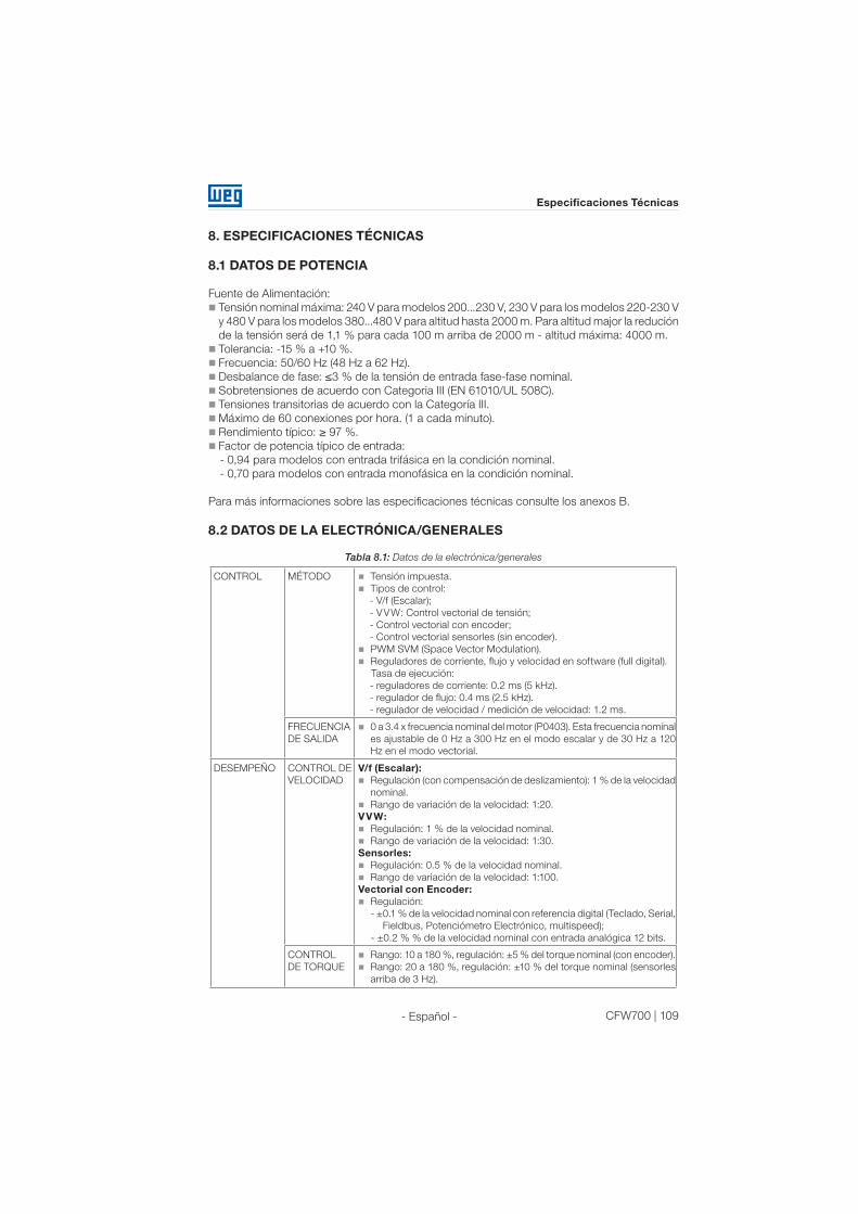
CFW700 | 109
Especificaciones Técnicas
- Español -
8. ESPECIFICACIONES TÉCNICAS
8.1 DATOS DE POTENCIA
Fuente de Alimentación:
Tensión nominal máxima: 240 V para modelos 200...230 V, 230 V para los modelos 220-230 V
y 480 V para los modelos 380...480 V para altitud hasta 2000 m. Para altitud major la redución
de la tensión será de 1,1 % para cada 100 m arriba de 2000 m - altitud máxima: 4000 m.
Tolerancia: -15 % a +10 %.
Frecuencia: 50/60 Hz (48 Hz a 62 Hz).
Desbalance de fase: ≤3 % de la tensión de entrada fase-fase nominal.
Sobretensiones de acuerdo con Categoria III (EN 61010/UL 508C).
Tensiones transitorias de acuerdo con la Categoría III.
Máximo de 60 conexiones por hora. (1 a cada minuto).
Rendimiento típico: ≥ 97 %.
Factor de potencia típico de entrada:
- 0,94 para modelos con entrada trifásica en la condición nominal.
- 0,70 para modelos con entrada monofásica en la condición nominal.
Para más informaciones sobre las especificaciones técnicas consulte los anexos B.
8.2 DATOS DE LA ELECTRÓNICA/GENERALES
Tabla 8.1: Datos de la electrónica/generales
CONTROL MÉTODO Tensión impuesta.
Tipos de control:
- V/f (Escalar);
- VVW: Control vectorial de tensión;
- Control vectorial con encoder;
- Control vectorial sensorles (sin encoder).
PWM SVM (Space Vector Modulation).
Reguladores de corriente, flujo y velocidad en software (full digital).
Tasa de ejecución:
- reguladores de corriente: 0.2 ms (5 kHz).
- regulador de flujo: 0.4 ms (2.5 kHz).
- regulador de velocidad / medición de velocidad: 1.2 ms.
FRECUENCIA
DE SALIDA
0 a 3.4 x frecuencia nominal del motor (P0403). Esta frecuencia nominal
es ajustable de 0 Hz a 300 Hz en el modo escalar y de 30 Hz a 120
Hz en el modo vectorial.
DESEMPEÑO CONTROL DE
VELOCIDAD
V/f (Escalar):
Regulación (con compensación de deslizamiento): 1 % de la velocidad
nominal.
Rango de variación de la velocidad: 1:20.
VVW:
Regulación: 1 % de la velocidad nominal.
Rango de variación de la velocidad: 1:30.
Sensorles:
Regulación: 0.5 % de la velocidad nominal.
Rango de variación de la velocidad: 1:100.
Vectorial con Encoder:
Regulación:
- ±0.1 % de la velocidad nominal con referencia digital (Teclado, Serial,
Fieldbus, Potenciómetro Electrónico, multispeed);
- ±0.2 % % de la velocidad nominal con entrada analógica 12 bits.
CONTROL
DE TORQUE
Rango: 10 a 180 %, regulación: ±5 % del torque nominal (con encoder).
Rango: 20 a 180 %, regulación: ±10 % del torque nominal (sensorles
arriba de 3 Hz).
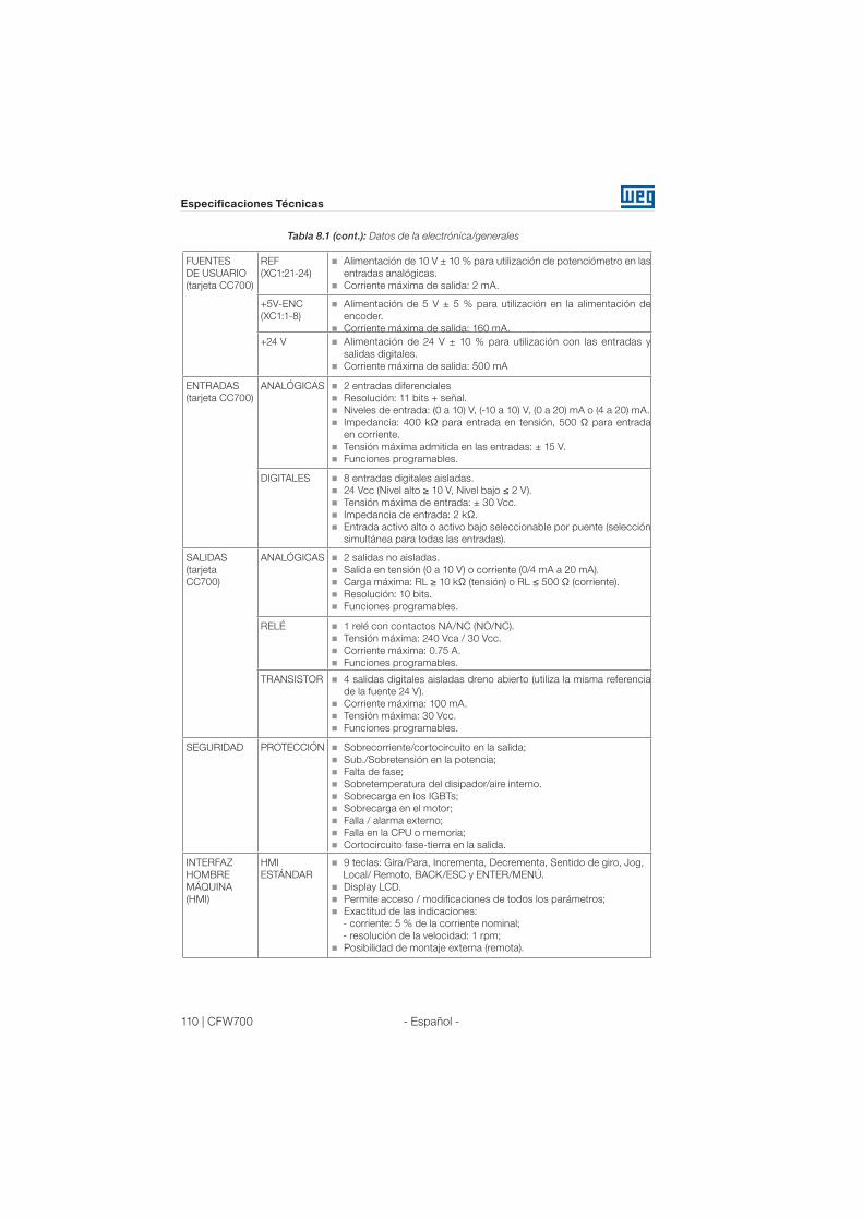
110 | CFW700
Especificaciones Técnicas
- Español -
FUENTES
DE USUARIO
(tarjeta CC700)
REF
(XC1:21-24)
Alimentación de 10 V ± 10 % para utilización de potenciómetro en las
entradas analógicas.
Corriente máxima de salida: 2 mA.
+5V-ENC
(XC1:1-8)
Alimentación de 5 V ± 5 % para utilización en la alimentación de
encoder.
Corriente máxima de salida: 160 mA.
+24 V Alimentación de 24 V ± 10 % para utilización con las entradas y
salidas digitales.
Corriente máxima de salida: 500 mA
ENTRADAS
(tarjeta CC700)
ANALÓGICAS 2 entradas diferenciales
Resolución: 11 bits + señal.
Niveles de entrada: (0 a 10) V, (-10 a 10) V, (0 a 20) mA o (4 a 20) mA.
Impedancia: 400 kΩ para entrada en tensión, 500 Ω para entrada
en corriente.
Tensión máxima admitida en las entradas: ± 15 V.
Funciones programables.
DIGITALES 8 entradas digitales aisladas.
24 Vcc (Nivel alto ≥ 10 V, Nivel bajo ≤ 2 V).
Tensión máxima de entrada: ± 30 Vcc.
Impedancia de entrada: 2 kΩ.
Entrada activo alto o activo bajo seleccionable por puente (selección
simultánea para todas las entradas).
SALIDAS
(tarjeta
CC700)
ANALÓGICAS 2 salidas no aisladas.
Salida en tensión (0 a 10 V) o corriente (0/4 mA a 20 mA).
Carga máxima: RL ≥ 10 kΩ (tensión) o RL ≤ 500 Ω (corriente).
Resolución: 10 bits.
Funciones programables.
RELÉ 1 relé con contactos NA/NC (NO/NC).
Tensión máxima: 240 Vca / 30 Vcc.
Corriente máxima: 0.75 A.
Funciones programables.
TRANSISTOR 4 salidas digitales aisladas dreno abierto (utiliza la misma referencia
de la fuente 24 V).
Corriente máxima: 100 mA.
Tensión máxima: 30 Vcc.
Funciones programables.
SEGURIDAD PROTECCIÓN Sobrecorriente/cortocircuito en la salida;
Sub./Sobretensión en la potencia;
Falta de fase;
Sobretemperatura del disipador/aire interno.
Sobrecarga en los IGBTs;
Sobrecarga en el motor;
Falla / alarma externo;
Falla en la CPU o memoria;
Cortocircuito fase-tierra en la salida.
INTERFAZ
HOMBRE
MÁQUINA
(HMI)
HMI
ESTÁNDAR
9 teclas: Gira/Para, Incrementa, Decrementa, Sentido de giro, Jog,
Local/ Remoto, BACK/ESC y ENTER/MENÚ.
Display LCD.
Permite acceso / modificaciones de todos los parámetros;
Exactitud de las indicaciones:
- corriente: 5 % de la corriente nominal;
- resolución de la velocidad: 1 rpm;
Posibilidad de montaje externa (remota).
Tabla 8.1 (cont.): Datos de la electrónica/generales

CFW700 | 111
Especificaciones Técnicas
- Español -
GRADO DE
PROTECCIÓN
IP20 Modelos de los tamaños A, B y C sin tapa superior y kit Nema1.
Modelos del tamaño E sin kit Nema1.
NEMA1/IP20 Modelos del tamaño D sin kit IP21.
Modelos del tamaño E con kit Nema1 (KN1E-01 o KN1E-02).
IP21 Modelos de los tamaños A, B y C con tapa superior.
NEMA1/IP21 Modelos de los tamaños A, B y C con tapa superior y kit Nema1.
Modelos del tamaño D con kit IP21.
IP54 Parte trasera del convertidor (parte externa para montaje en brida).
8.2.1 Normativas Atendidas
Tabla 8.2: Normativas atendidas
NORMAS DE
SEGURIDAD
UL 508C - Power Power conversion equipment.
UL 840 -Insulation coordination including clearances and creepage distances
for electrical equipment.
EN61800-5-1 - Safety requirements electrical, thermal and energy.
EN 50178 - Electronic equipment for use in power installations.
EN 60204-1 - Safety of machinery. Electrical equipment of machines. Part 1:
General requirements.
Nota: Para tener una máquina en conformidad con esa normativa, el fabricante
de la máquina es responsable por la instalación de un dispositivo para la
parada de emergencia y un equipamiento para seccionar la red eléctrica.
EN 60146 (IEC 146) - Semiconductor converters.
EN 61800-2 -Adjustable speed electrical power drive systems - Part 2: General
requirements - Rating specifications for low voltage adjustable frequency AC
power drive systems.
NORMAS DE
COMPATIBILIDAD
ELECTROMAGNÉTICA
(EMC)
EN 61800-3 - Adjustable speed electrical power drive systems - Part 3: EMC
product standard including specific test methods.
EN 55011 - Limits and methods of measurement of radio disturbance
characteristics of industrial, scientific and medical (ISM) radio-frequency
equipment.
CISPR 11 -Industrial, scientific and medical (ISM) radio-frequency equipment
– Electromagnetic disturbance characteristics - Limits and methods of
measurement.
EN 61000-4-2 -Electromagnetic compatibility (EMC) - Part 4: Testing and
measurement techniques - Section 2: Electrostatic discharge immunity test.
EN 61000-4-3 -Electromagnetic compatibility (EMC) - Part 4: Testing and
measurement techniques -Section 3: Radiated, radio-frequency, electromagnetic
field immunity test.
EN 61000-4-4 -Electromagnetic compatibility (EMC) - Part 4: Testing and
measurement techniques - Section 4: Electrical fast transient/burst immunity
test.
EN 61000-4-5 -Electromagnetic compatibility (EMC) - Part 4: Testing and
measurement techniques - Section 5: Surge immunity test.
EN 61000-4-6 -Electromagnetic compatibility (EMC) - Part 4: Testing and
measurement techniques - Section 6: Immunity to conducted disturbances,
induced by radio-frequency fields.
NORMAS DE
CONSTRUCCIÓN
MECÁNICA
EN 60529 - Degrees of protection provided by enclosures (IP code).
UL 50 - Enclosures for electrical equipment.
Tabla 8.1 (cont.): Datos de la electrónica/generales

112 | CFW700
Especificaciones Técnicas
- Español -

CFW700 | 165
Appendix A / Anexo A
Ap
pen
dix
AA
nexo
A
APPENDIX A - DIAGRAMS AND FIGURES
ANEXO A - DIAGRAMAS Y FIGURAS
ANEXO A - DIAGRAMAS E FIGURAS
3
11
9 4
5
8 7
2
12
1
10
1
3
2
5
4
6
8
9
10
1
Frames A, B and C / Mecánica A, B y C /
Mecânicas A, B e C
Frames D and E / Mecánica D y E /
Mecânicas D e E
1 - Mounting supports (for through
the wall mounting)
2 - Rear part of the inverter
(external
part for flange mounting)
3 - Fan with mounting support
4 - Control accessory module
(refer
to the section 7.2 - Accesories)
5 - FLASH memory module (not
included)
6 - Front cover (frame A, B and C)
7 - Control rack cover (frame D
and E)
8 - Keypad
9 - Status LED
10 - CC700 control board
11 - Bottom front cover (frame
D and E)
12 - Hoisting eye (only frame E)
1 - Soporte de fijación (para el montaje en
superficie)
2 - Parte trasera del convertidor (parte
externa para montaje en brida)
3 - Ventilador con soporte de fijación
4 - Módulo accesorio de control (consulte
ítem 7.2 - Accesorios)
5 - Módulo de memoria FLASH (no incluido)
6 - Tapa frontal (mecánica A, B y C)
7 - Tapa del rack de control (mecánica D y E)
8 - HMI
9 - LED de estado (STATUS)
10 - Tarjeta de control CC700
11 - Tapa frontal inferior (mecánica D y E)
12 - Chapa para izaje (solamente
mecánica E)
1 - Suportes de fixação (para montagem em
superfície)
2 - Parte traseira do inversor (parte externa para
montagem em flange)
3 - Ventilador com suporte de fixação
4 - Módulo acessório de controle (consulte item
7.2 - Acessórios).
5 - Módulo de memória FLASH (não incluído)
6 - Tampa frontal (mecânica A, B e C)
7 - Tampa do rack de controle (mecânica D e E)
8 - HMI
9 - LED de estado (STATUS)
10 - Cartão de controle CC700
11 - Tampa frontal inferior (mecânica D e E)
12 - Chapa para içamento (somente
mecânica E)
Figure A.1: Main components of the CFW700
Figura A.1: Principales componentes del CFW700
Figura A.1: Componentes principais do CFW700
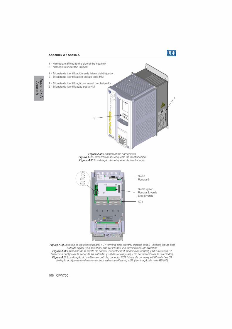
166 | CFW700
Appendix A / Anexo A
Ap
pend
ix AA
nexo A
1 - Nameplate affixed to the side of the heatsink
2 - Nameplate under the keypad
1 - Etiqueta de identificación en la lateral del disipador
2 - Etiqueta de identificación debajo de la HMI
1 - Etiqueta de identificação na lateral do dissipador
2 - Etiqueta de identificação sob a HMI
Figure A.2: Location of the nameplates
Figura A.2: Ubicación de las etiquetas de identificación
Figura A.2: Localização das etiquetas de identificação
Figure A.3: Location of the control board, XC1 terminal strip (control signals), and S1 (analog inputs and
outputs signal type selection) and S2 (RS485 line termination) DIP-switches
Figura A.3: Ubicación de la tarjeta de control, conector XC1 (señales de control) y DIP-switches S1
(selección del tipo de la señal de las entradas y salidas analógicas) y S2 (terminación de la red RS485)
Figura A.3: Localização do cartão de controle, conector XC1 (sinais de controle) e DIP-switches S1
(seleção do tipo de sinal das entradas e saídas analógicas) e S2 (terminação da rede RS485)
1
Slot 5
Ranura 5
XC1
Slot 3: green
Ranura 3: verde
Slot 3: verde
2
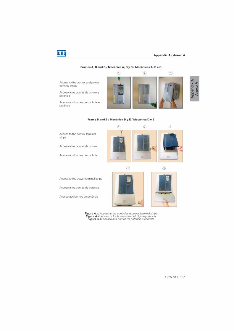
CFW700 | 167
Appendix A / Anexo A
Ap
pen
dix
AA
nexo
A
Figure A.4: Access to the control and power terminal stripsFigura A.4: Acceso a los bornes de control y de potencia
Figura A.4: Acesso aos bornes de potência e controle
Frames A, B and C / Mecánica A, B y C / Mecânicas A, B e C
Access to the control and power
terminal strips
Acceso a los bornes de control y
potencia
Acesso aos bornes de controle e
potência
1 2 3
Frame D and E / Mecánica D y E / Mecânica D e E
Access to the control terminal
strips
Acceso a los bornes de control
Acesso aos bornes de controle
1 2 3
Access to the power terminal strips
Acceso a los bornes de potencia
Acesso aos bornes de potência
1 2
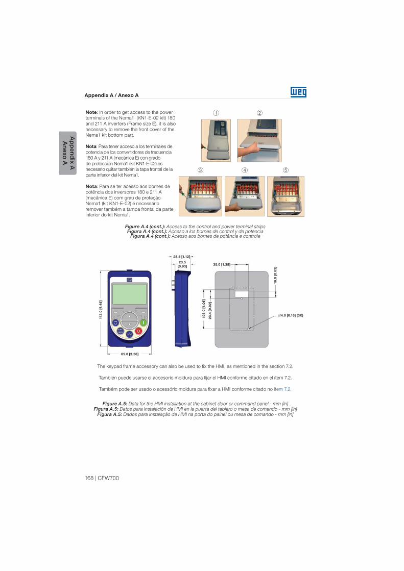
168 | CFW700
Appendix A / Anexo A
Ap
pend
ix AA
nexo A
Note: In order to get access to the power
terminals of the Nema1 (KN1-E-02 kit) 180
and 211 A inverters (Frame size E), it is also
necessary to remove the front cover of the
Nema1 kit bottom part.
Nota: Para tener acceso a los terminales de
potencia de los convertidores de frecuencia
180 A y 211 A (mecánica E) con grado
de protección Nema1 (kit KN1-E-02) es
necesario quitar también la tapa frontal de la
parte inferior del kit Nema1.
Nota: Para se ter acesso aos bornes de
potência dos inversores 180 e 211 A
(mecânica E) com grau de proteção
Nema1 (kit KN1-E-02) é necessário
remover também a tampa frontal da parte
inferior do kit Nema1.
3 4 5
1 2
Figure A.4 (cont.): Access to the control and power terminal stripsFigura A.4 (cont.): Acceso a los bornes de control y de potencia
Figura A.4 (cont.): Acesso aos bornes de potência e controle
Figure A.5: Data for the HMI installation at the cabinet door or command panel - mm [in]Figura A.5: Datos para instalación de HMI en la puerta del tablero o mesa de comando - mm [in]
Figura A.5: Dados para instalação de HMI na porta do painel ou mesa de comando - mm [in]
35.0 [1.38]
28.5 [1.12]
113
.0 [
4.4
5]
10
3.0
[4
.06
]
23
.4 [
0.9
2]
16
.0 [
0.6
3]
23.5
[0.93]
65.0 [2.56]
4.0 [0.16] (3X)
The keypad frame accessory can also be used to fix the HMI, as mentioned in the section 7.2.
También puede usarse el accesorio moldura para fijar el HMI conforme citado en el ítem 7.2.
Também pode ser usado o acessório moldura para fixar a HMI conforme citado no item 7.2.

CFW700 | 169
Appendix A / Anexo A
Ap
pen
dix
AA
nexo
A
Figure A.6 (a): Grounding points and the location of filter capacitors ground disconnection points - disconnection trough bolts
Figura A.6 (a): Puntos de puesta a tierra y ubicación de los puntos de desconexión de puesta a tierra de los capacitores del filtro - desconexión vía tornillos
Figura A.6 (a): Pontos de aterramento e localização dos pontos de desconexão de aterramento dos capacitores de filtro - desconexão via parafusos
Frame A / Mecánica A / Mecânica A
Inverter without the front cover
Convertidor sin la tapa frontal
Inversor sem a tampa frontal
Frame B / Mecánica B / Mecânica B
Inverter without the front cover
Convertidor sin la tapa frontal
Inversor sem a tampa frontal
Frame C / Mecánica C / Mecânica C
Inverter without the front cover
Convertidor sin la tapa frontal
Inversor sem a tampa frontal
Frame D / Mecánica D / Mecânica D
Inverter without the bottom front cover
Convertidor sin la tapa frontal inferior
Inversor sem a tampa frontal inferior
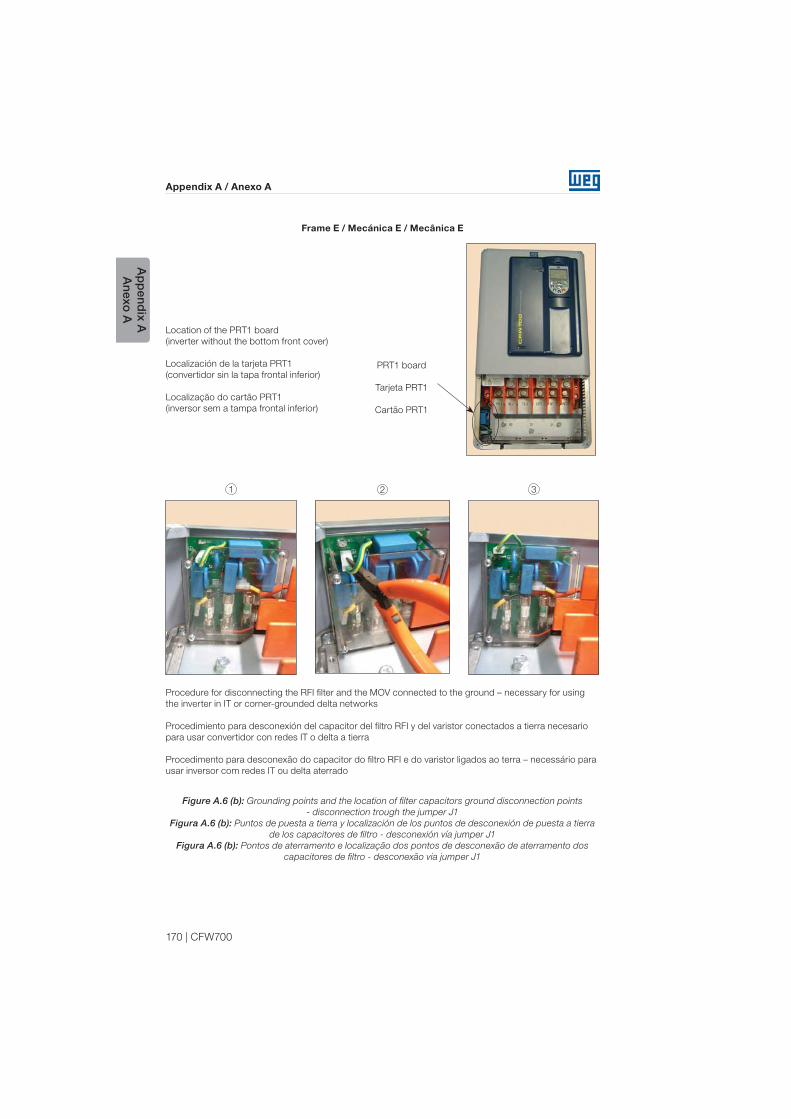
170 | CFW700
Appendix A / Anexo A
Ap
pend
ix AA
nexo A
Frame E / Mecánica E / Mecânica E
Location of the PRT1 board
(inverter without the bottom front cover)
Localización de la tarjeta PRT1
(convertidor sin la tapa frontal inferior)
Localização do cartão PRT1
(inversor sem a tampa frontal inferior)
PRT1 board
Tarjeta PRT1
Cartão PRT1
1 2 3
Procedure for disconnecting the RFI filter and the MOV connected to the ground – necessary for using
the inverter in IT or corner-grounded delta networks
Procedimiento para desconexión del capacitor del filtro RFI y del varistor conectados a tierra necesario
para usar convertidor con redes IT o delta a tierra
Procedimento para desconexão do capacitor do filtro RFI e do varistor ligados ao terra – necessário para
usar inversor com redes IT ou delta aterrado
Figure A.6 (b): Grounding points and the location of filter capacitors ground disconnection points
- disconnection trough the jumper J1
Figura A.6 (b): Puntos de puesta a tierra y localización de los puntos de desconexión de puesta a tierra
de los capacitores de filtro - desconexión vía jumper J1
Figura A.6 (b): Pontos de aterramento e localização dos pontos de desconexão de aterramento dos
capacitores de filtro - desconexão via jumper J1

CFW700 | 171
Appendix A / Anexo A
Ap
pen
dix
AA
nexo
A
Frame A / Mecánica A / Mecânica A
Frame C / Mecánica C / Mecânica C
Frame B / Mecánica B / Mecânica B
Frame D / Mecánica D / Mecânica D
Figure A.7: IP21 protection degree inverter - frame sizes A to DFigura A.7: Convertidor de frecuencia con grado de protección IP21 - mecánica A a D
Figura A.7: Inversor com grau de proteção IP21 - mecânica A a D

172 | CFW700
Appendix A / Anexo A
Ap
pend
ix AA
nexo A

CFW700 | 173
Appendix B / Anexo B
Ap
pen
dix
BA
nexo
B
APPENDIX B – TECHNICAL ESPECIFICATIONS
ANEXO B – ESPECIFICACIONES TÉCNICAS
ANEXO B – ESPECIFICAÇÕES TÉCNICAS
Table B.1: List of models of CFW700 series, main electrical specifications – models 200 V
Tabla B.1: Relación de modelos de la línea CFW700, especificaciones eléctricas principales – modelos 200 V
Tabela B.1: Relação de modelos da linha CFW700, especificações elétricas principais – modelos 200 V
Th
e n
ote
s fo
r ta
ble
s B
.1 a
nd
B.2
are
lo
cate
d a
fter
the t
ab
le B
.2.
Las n
ota
s d
e las t
ab
las B
.1 y
B.2
está
n d
esp
ués d
e la t
ab
la B
.2.
As n
ota
s d
a t
ab
ela
B.1
e B
.2 e
stã
o a
pó
s a
tab
ela
B.2
.
Inverter Convertidor
Inversor
Number of input phases N° de fases de alimentaciónN° de fases de alimentação
Power supply rated voltage Tensión nominal de alimentaciónTensão nominal de alimentação
Frame size /MecánicaMecânica
Output rated currentCorriente de salida
nominalCorrente nominal
de saída(1)
Maximum motor Motor máximo
(2)
Recommended fuse Fusible recomendadoFusível recomendado
Power wire size Calibre de los cables de potenciaBitola dos cabos de potência (3)
Grounding wire size Calibre del cable de puesta a tierraBitola do cabo de aterramento (3)
Dyn
amic
bra
kin
g
Fre
nad
o r
eost
átic
oF
ren
agem
reo
stát
ica
(4)
Maximum current Corriente máximaCorrente máxima
Recommended resistor Resistor recomendado
Braking rms current Corriente eficaz de frenado
Corrente eficaz de frenagem
Power wire size for DC+ and BR terminals
Calibre de los cables +UD y BRBitola dos cabos +UD e BR (3)
ND
HD
ND
HD
UL
(IE
C)
i²t
(In
om
ND
)(In
om
HD
)(I
ma
x)
[Vrm
s][A
rms]
[Arm
s][H
P/k
W]
[HP
/kW
][A
][A
²s]
[mm
²][A
WG
]m
m²
(AW
G)
[A]
[Ω]
[A]
mm
² (A
WG
)C
FW
70
0A
06
P0
S2
1
22
0 ...
24
0
A
65
1.5
/1.1
1.5
/1.1
16 (15
)42
02.5
/1.5
(7)
14
2.5
(14)
7.8
51
5.2
1.5
(16
)
CF
W70
0A
07P
0S
27
72
/1.5
2/1
.516 (15
)42
02.5
/1.5
(7)
12
/14 (7
)2.5
(12)
12.1
33
7.0
1.5
(16
)
CF
W70
0A
10
P0
S2
10
10
3/2
.23
/2.2
25
(25
)10
00
6/2
.5 (7
)10
/14 (7
)6 (10
)14.8
27
10
.82.5
(14)
CF
W70
0A
06
P0
B2
1/3
65
1.5
/1.1
1.5
/1.1
16 (15
)42
01.5
/2.5
(5)
14
2.5
(14)
7.8
51
5.2
1.5
(16
)
CF
W70
0A
07P
0B
27
72
/1.5
2/1
.52
0/1
6
(20
/15
) (5
)42
01.5
/2.5
(5)
14
/12 (5
)2.5
(12)
12.1
33
7.0
1.5
(16
)
CF
W70
0A
07P
0T
2
3
75
.52
/1.5
1.5
/1.1
16 (15
)42
01.5
14
2.5
(14)
7.8
51
5.2
1.5
(16
)
CF
W70
0A
10
P0
T2
10
83
/2.2
2/1
.516 (15
)42
02.5
14
2.5
(14)
12.1
33
7.0
1.5
(16
)
CF
W70
0A
13
P0
T2
13
11
4/3
.03
/2.2
16
(2
0)
42
02.5
12
2.5
(12)
14.8
27
8.5
2.5
(14)
CF
W70
0A
16
P0
T2
16
13
5/3
.74
/3.0
25
(25
)42
04
12
4 (12)
20
.02
014.4
4 (12)
CF
W70
0B
24
P0
T2
B
24
20
7.5
/5.5
6/4
.525 (25
)10
00
610
6 (10
)2
6.7
15
19.2
6 (10
)
CF
W70
0B
28
P0
T2
28
24
10
/7.5
7.5
/5.5
35 (3
5)
10
00
68
6 (8
)3
0.8
13
18
.26 (10
)
CF
W70
0B
33
P5
T2
33
.528
12.5
/9.2
10
/7.5
50 (5
0)
10
00
10
810 (8
)3
0.8
13
16
.76 (10
)
CF
W70
0C
45
P0
T2
C
45
36
15
/11
12.5
/9.2
50 (5
0)
275
010
610 (6
)4
4.0
9.1
33
.310 (8
)
CF
W70
0C
54
P0
T2
54
45
20
/15
15
/11
63
(70
)275
016
616
(6
)4
8.8
8.2
32.2
10 (8
)
CF
W70
0C
70
P0
T2
70
56
25
/18
.52
0/1
58
0 (8
0)
275
025
416
(4)
48
.88
.22
6.1
6 (8
)
CF
W70
0D
86
P0
T2
D
86
70
30
/22
25
/18
.510
0 (10
0)
315
03
52
16 (4)
13
33
.09
0.7
35
(2)
CF
W70
0D
010
5T
210
58
64
0/3
03
0/2
2125 (125
)315
05
01
25 (4)
13
33
.09
0.9
35 (2)
CF
W70
0E
0142
T2
22
0 /
23
0E
142
115
50
/37
40
/30
20
0 (2
00
)3
92
00
70 /
50 (6
)1/0
/2
/0 (6
)3
5 (2)
267
1.5
142
2x25 (2
x4)
CF
W70
0E
018
0T
218
0142
60
/45
50
/37
20
0 (2
00
)218
00
02
x3
5 /
2x25 (6
)2
x2 /
2x4 (6
)5
0 (1)
267
1.5
18
02
x3
5 (2
x2)
CF
W70
0E
0211T
2211
18
075
/55
75
/55
25
0 (25
0)
218
00
02
x5
0 /
2x3
5 (6
)2
x1 /
2x2 (6
)70 (2
/0)
33
31.2
211
2x5
0 (2
x1)
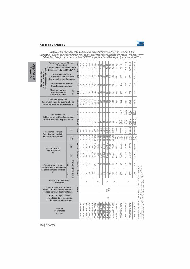
174 | CFW700
Appendix B / Anexo B
Ap
pend
ix BA
nexo B
Table B.2: List of models of CFW700 series, main electrical specifications – models 400 V
Tabla B.2: Relación de modelos de la línea CFW700, especificaciones eléctricas principales – modelos 400 V
Tabela B.2: Relação de modelos da linha CFW700, especificações elétricas principais – modelos 400 V
Th
e n
ote
s fo
r ta
ble
s B
.1 a
nd
B.2
are
lo
cate
d a
fter
the t
ab
le B
.2.
Las n
ota
s d
e las t
ab
las B
.1 y
B.2
está
n d
esp
ués d
e la t
ab
la B
.2.
As n
ota
s d
a t
ab
ela
B.1
e B
.2 e
stã
o a
pó
s a
tab
ela
B.2
.
Inverter Convertidor
Inversor
Number of input phases N° de fases de alimentaciónN° de fases de alimentação
Power supply rated voltage Tensión nominal de alimentaciónTensão nominal de alimentação
Frame size /MecánicaMecânica
Output rated currentCorriente de salida nominalCorrente nominal de saída
(1)
Maximum motor Motor máximo
(2)
Recommended fuse Fusible recomendadoFusível recomendado
Power wire size Calibre de los cables de potenciaBitola dos cabos de potência (3)
Grounding wire size Calibre del cable de puesta a tierraBitola do cabo de aterramento (3)
Dyn
amic
bra
kin
g
Fre
nad
o r
eost
átic
oF
ren
agem
reo
stát
ica
(4)
Maximum current Corriente máximaCorrente máxima
Recommended resistor Resistor recomendado
Braking rms current Corriente eficaz de frenado
Corrente eficaz de frenagem
Power wire size for DC+ and BR terminals
Calibre de los cables +UD y BRBitola dos cabos +UD e BR (3)
ND
HD
ND
HD
UL
(IE
C)
i²t
(In
om
ND
)(In
om
HD
)(I
ma
x)
[Vrm
s][A
rms]
[Arm
s][H
P/k
W]
[HP
/kW
][A
][A
²s]
[mm
²][A
WG
]m
m²
(AW
G)
[A]
[Ω]
[A]
mm
² (A
WG
)
CF
W70
0A
03
P6
T4
33
80 ...
48
0
A
3.6
3.6
2/1
.52
/1.5
16 (15
)19
01.5
14
2.5
(14)
8.0
10
03
.51.5
(16
)
CF
W70
0A
05
P0
T4
55
3/2
.23
/2.2
16 (15
)19
01.5
14
2.5
(14)
8.0
10
05
.21.5
(16
)
CF
W70
0A
07P
0T4
75
.54
/33
/2.2
16 (15
)19
01.5
14
2.5
(14)
8.0
10
05
.21.5
(16
)
CF
W70
0A
10
P0
T4
10
10
6/4
.56
/4.5
16 (15
)4
95
2.5
14
2.5
(14)
14.3
56
8.6
2.5
(14)
CF
W70
0A
13
P5
T4
13
.511
7.5
/5.5
6/4
.516 (2
0)
49
52.5
12
2.5
(12)
14.3
56
10
.42.5
(14)
CF
W70
0B
17P
0T4
B
17
13
.510
/7.5
7.5
/5.5
25
(25
)4
95
410
4 (10
)14.3
56
12.6
2.5
(14)
CF
W70
0B
24
P0T4
24
19
15
/11
10
/7.5
35 (3
5)
50
06
10
6 (10
)3
6.4
22
16
.64 (10
)
CF
W70
0B
31P
0T4
31
25
20
/15
15
/11
35
(3
5)
125
010
810
(8
)4
0.0
20
20
.56 (10
)
CF
W70
0C
38
P0
T4
C
38
33
25
/18
.52
0/1
55
0 (5
0)
125
010
810
(8
)4
0.0
20
26
.16 (8
)
CF
W70
0C
45
P0
T4
45
38
30
/22
25
/18
.55
0 (5
0)
210
010
610
(6
)6
6.7
12
40
.010
(8
)
CF
W70
0C
58
P5
T4
58
.547
40
/30
30
/22
63
(70
)210
016
416
(4)
66
.712
31.7
10
(8
)
CF
W70
0D
70
P5
T4
D
70
.561
50
/37
40
/30
80 (8
0)
210
025
316 (4)
66
.712
42.9
10 (6
)
CF
W70
0D
88
P0
T4
88
73
60
/45
50
/37
10
0
(10
0)
315
03
52
16 (4)
12
96
.26
3.1
25 (4)
CF
W70
0E
010
5T4
E
10
58
875
/55
60
/45
125
(125
)3
92
00
50 /
3
5 (6
)1 /
2 (6
)25 (4)
18
64.3
10
55
0 (1)
CF
W70
0E
0142
T4
142
115
10
0/7
575
/55
20
0
(20
0)
39
20
070 /
5
0 (6
)2
/0 /
1/0
(6)
35 (2)
267
3.0
142
2x25 (2
x4)
CF
W70
0E
018
0T4
18
0142
15
0/1
10
10
0/7
52
00
(20
0)
218
00
02
x3
5 /
2
x25 (6
)2
x2 /
2
x4 (6
)5
0 (1)
267
3.0
18
02
x3
5 (2
x2)
CF
W70
0E
0211T4
211
18
0175
/13
215
0/1
10
25
0
(25
0)
218
00
02
x5
0 /
2
x3
5 (6
)2
x1 /
2
x2 (6
)70 (2
/0)
36
42.2
191.7
2x5
0 (2
x1)

CFW700 | 175
Appendix B / Anexo B
Ap
pen
dix
BA
nexo
B
Notes:(1) Rated current considering the switching frequency and surrounding inverter temperature specified in
table, and the environmental conditions specified in the section 3.1.1 - Installation Environmet.
(2) Orienting value considering a 230 V or 460 V, IV pole WEG motor. The inverter sizing must be based on
the current consumed by the motor in the application.
(3) Use only copper wiring with a minimum of 75 °C temperature specification. For more information on the
power terminals, refer to the table B.5.
(4) The inverter must have the DB suffix in the name (smart code).
(5) The first number refers to the three-phase and the second to the single-phase supply. In case of single-
phase supply, use cable with greater gauge only at the terminals R/L1/L and S/L2/N.
(6) The first number refers to ND application and the second to HD application.
(7) The first number refers to the cables used at the terminals R/L1/L and S/L2/N, whereas the second
number refers to the other power cables.
Notas:(1) Corriente nominal considerando la frecuencia de conmutación y la temperatura alrededor del convertidor
especificadas en la tabla y las condiciones ambientales especificadas en el ítem 3.1.1 - Condiciones
Ambientales.
(2) Valor orientativo considerando motor WEG 230 V o 460 V, 4 polos. El dimensionamiento del convertidor
debe realizarse con base en la corriente consumida por el motor en la aplicación.
(3) Usar solamente cableado de cobre con especificación de temperatura mínima de 75 °C. Para más
informaciones sobre los bornes de potencia consulte la tabla B.5.
(4) El convertidor debe poseer el sufijo DB en la nomenclatura (código inteligente).
(5) El primer número se refiere a la alimentación trifásica y el segundo número a la alimentación monofásica.
En caso de alimentación monofásica usar cable con calibre mayor solamente en los bornes R/L1/L y S/
L2/N.
(6) El primer número se refiere a la aplicación ND y el segundo número a la aplicación HD.
(7) El primer número se refiere a los cables usados en los bornes R/L1/L y S/L2/N mientras que el segundo
número se refiere a los demás cables de potencia.
Notas:(1) Corrente nominal considerando-se a frequência de chaveamento e temperatura ao redor do inversor
especificadas na tabela e as condições ambientais especificadas no item 3.1.1 - Condições Ambientais.
(2) Valor orientativo considerando-se motor WEG 230 V ou 460 V, 4 pólos. O dimensionamento do inversor
deve ser feito com base na corrente consumida pelo motor na aplicação.
(3) Usar somente fiação de cobre com especificação de temperatura de no mínimo 75 °C. Para mais
informações sobre os bornes de potência consulte a tabela B.5.
(4) O inversor deve possuir o sufixo DB na nomenclatura (código inteligente).
(5) O primeiro número refere-se à alimentação trifásica e o segundo número à alimentação monofásica.
No caso de alimentação monofásica usar cabo com bitola maior somente nos bornes R/L1/L e S/L2/N.
(6) O primeiro número refere-se à aplicação ND e o segundo número à aplicação HD.
(7) O primeiro número refere-se aos casos usados nos bornes R/L1/L e S/L2/N enquanto que o segundo
número refere-se aos demais cabos de potência.
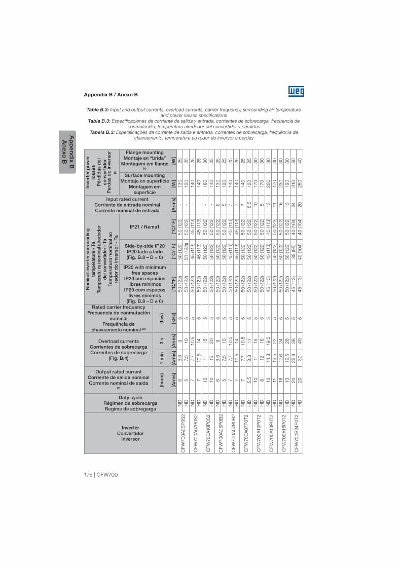
176 | CFW700
Appendix B / Anexo B
Ap
pend
ix BA
nexo B
Table B.3: Input and output currents, overload currents, carrier frequency, surrounding air temperature
and power losses specifications
Tabla B.3: Especificaciones de corriente de salida y entrada, corrientes de sobrecarga, frecuencia de
conmutación, temperatura alrededor del convertidor y pérdidas
Tabela B.3: Especificações de corrente de saída e entrada, correntes de sobrecarga, frequência de
chaveamento, temperatura ao redor do inversor e perdas
InverterConvertidor
Inversor
Duty cycleRégimen de sobrecargaRegime de sobregarga
Output rated currentCorriente de salida nominalCorrente nominal de saída
(1)
Overload currentsCorrientes de sobrecargaCorrentes de sobrecarga
(Fig. B.4)
Rated carrier frequencyFrecuencia de conmutación
nominal Frequência de
chaveamento nominal (2)
Nom
inal
inve
rter
sur
roun
din
g
tem
per
atur
e -
TaTe
mp
erat
u ra
nom
inal
alre
ded
or
del
con
vert
idor
- T
aTe
mp
erat
ura
no
min
al a
o
red
or
do
inve
rso
r -
Ta
Input rated currentCorriente de entrada nominalCorrente nominal de entrada
Inve
rter
po
wer
lo
sses
Pér
did
as d
el
conv
erti
do
rP
erd
as d
o in
vers
or
(3)
IP20 with minimumfree spaces
IP20 con espacios libres mínimos
IP20 com espaçoslivres mínimos
(Fig. B.8 – D ≠ 0)
Side-by-side IP20IP20 lado a lado(Fig. B.8 – D = 0)
IP21 / Nema1
Surface mountingMontaje en superficie
Montagem em superfície
Flange mountingMontaje en “brida”
Montagem em flange(4)
(In
om
)1
min
3 s
(fsw
)
[Arm
s][A
rms]
[Arm
s][k
Hz]
[°C
/°F
][°
C/°
F]
[°C
/°F
][A
rms]
[W]
[W]
CF
W70
0A
06
P0
S2
ND
66
.69
55
0 (12
2)
50
(12
2)
50
(12
2)
-13
025
HD
57.
510
55
0 (12
2)
50
(12
2))
50
(12
2)
-12
025
CF
W70
0A
07P
0S
2N
D7
7.7
10.5
55
0 (12
2)
45
(113
)4
5 (113
)-
14
025
HD
710.5
14
55
0 (12
2)
45
(113
)4
5 (113
)-
14
025
CF
W70
0A
10
P0
S2
ND
10
11
15
55
0 (12
2)
50 (12
2)
50 (12
2)
-18
03
0
HD
10
15
20
55
0 (12
2)
50
(12
2)
50
(12
2)
-14
025
CF
W70
0A
06
P0
B2
ND
66
.69
55
0 (12
2)
50
(12
2)
50
(12
2)
613
025
HD
57.
510
55
0 (12
2)
50
(12
2)
50
(12
2)
512
025
CF
W70
0A
07P
0B
2N
D7
7.7
10.5
55
0 (12
2)
45
(113
)4
5 (113
)7
14
025
HD
710.5
14
55
0 (12
2)
45
(113
)4
5 (113
)7
14
025
CF
W70
0A
07P
0T
2N
D7
7.7
10.5
55
0 (12
2)
50
(12
2)
50
(12
2)
714
025
HD
5.5
8.3
11
55
0 (12
2)
50
(12
2)
50
(12
2)
5.5
12
025
CF
W70
0A
10
P0T2
ND
10
11
15
55
0 (12
2)
50 (12
2)
50 (12
2)
10
170
30
HD
812
16
55
0 (12
2)
50
(12
2)
50
(12
2)
8170
30
CF
W70
0A
13
P0T
2N
D13
14.3
19.5
54
5 (113
)4
5 (113
)4
5 (113
)13
20
03
0
HD
11
16
.52
25
50 (12
2)
50 (12
2)
50 (12
2)
11
170
30
CF
W70
0A
16
P0T2
ND
16
17.
624
55
0 (12
2)
50 (12
2)
50 (12
2)
16
23
03
0
HD
13
19.5
26
55
0 (12
2)
50
(12
2)
50
(12
2)
13
19
03
0
CF
W70
0B
24
P0T2
ND
24
26
.43
65
45
(113
)3
5 (9
5)
40 (10
4)
24
310
50
HD
20
30
40
54
5 (113
)4
0 (10
4)
40
(10
4)
20
25
04
0
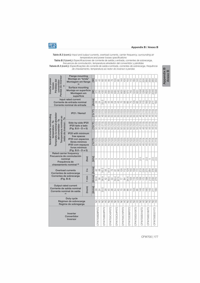
CFW700 | 177
Appendix B / Anexo B
Ap
pen
dix
BA
nexo
B
Table B.3 (cont.): Input and output currents, overload currents, carrier frequency, surrounding air
temperature and power losses specifications
Tabla B.3 (cont.): Especificaciones de corriente de salida y entrada, corrientes de sobrecarga,
frecuencia de conmutación, temperatura alrededor del convertidor y pérdidas
Tabela B.3 (cont.): Especificações de corrente de saída e entrada, correntes de sobrecarga, frequência
de chaveamento, temperatura ao redor do inversor e perdas
InverterConvertidor
Inversor
Duty cycleRégimen de sobrecargaRegime de sobregarga
Output rated currentCorriente de salida nominalCorrente nominal de saída
(1)
Overload currentsCorrientes de sobrecargaCorrentes de sobrecarga
(Fig. B.4)
Rated carrier frequencyFrecuencia de conmutación
nominal Frequência de
chaveamento nominal (2)
Nom
inal
inve
rter
sur
roun
din
g
tem
per
atur
e -
TaTe
mp
erat
u ra
nom
inal
alre
ded
or
del
con
vert
idor
- T
aTe
mp
erat
ura
no
min
al a
o
red
or
do
inve
rso
r -
Ta
Input rated currentCorriente de entrada nominalCorrente nominal de entrada
Inve
rter
po
wer
lo
sses
Pér
did
as d
el
conv
erti
do
rP
erd
as d
o in
vers
or
(3)
IP20 with minimumfree spaces
IP20 con espacios libres mínimos
IP20 com espaçoslivres mínimos
(Fig. B.8 – D ≠ 0)
Side-by-side IP20IP20 lado a lado(Fig. B.8 – D = 0)
IP21 / Nema1
Surface mountingMontaje en superficie
Montagem em superfície
Flange mountingMontaje en “brida”
Montagem em flange(4)
(In
om
)1
min
3 s
(fsw
)
[Arm
s][A
rms]
[Arm
s][k
Hz]
[°C
/°F
][°
C/°
F]
[°C
/°F
][A
rms]
[W]
[W]
CF
W70
0B
28
P0T2
ND
28
30.8
42
55
0 (12
2)
50 (12
2)
50 (12
2)
28
370
60
HD
24
36
48
55
0 (12
2)
50 (12
2)
50 (12
2)
24
29
04
0
CF
W70
0B
33
P5
T2
ND
33
.53
6.9
50.3
55
0 (12
2)
45
(113
)4
5 (113
)3
3.5
43
06
0
HD
28
42
56
55
0 (12
2)
50 (12
2)
50 (12
2)
28
35
05
0
CF
W70
0C
45
P0T2
ND
45
49.5
67.
55
50
(12
2)
50
(12
2)
50
(12
2)
45
59
09
0
HD
36
54
72
55
0 (12
2)
50 (12
2)
50 (12
2)
36
45
070
CF
W70
0C
54
P0T2
ND
54
59.4
81
55
0 (12
2)
50
(12
2)
50
(12
2)
54
68
010
0
HD
45
67.
59
05
50
(12
2)
50
(12
2)
50
(12
2)
45
54
08
0
CF
W70
0C
70
P0T2
ND
70
77
10
55
50
(12
2)
50
(12
2)
50
(12
2)
70
90
014
0
HD
56
84
112
55
0 (12
2)
50
(12
2)
50
(12
2)
56
68
010
0
CF
W70
0D
86
P0T2
ND
86
94.6
12
95
50
(12
2)
50
(12
2)
50
(12
2)
86
970
15
0
HD
70
10
514
05
50 (12
2)
50 (12
2)
50 (12
2)
70
74
0110
CF
W70
0D
010
5T
2N
D10
5116
15
85
50
(12
2)
50
(12
2)
50
(12
2)
10
512
00
18
0
HD
86
12
9172
55
0 (12
2)
50
(12
2)
50
(12
2)
86
92
014
0
CF
W70
0E
0142
T2
ND
142
15
6213
2.5
45
(113
)4
5 (113
)4
5 (113
)142
14
90
210
HD
115
172
23
05
45 (113
)4
5 (113
)4
5 (113
)115
128
02
00
CF
W70
0E
018
0T2
ND
18
019
8270
2.5
45
(113
)4
5 (113
)4
5 (113
)18
018
20
36
0
HD
142
213
28
45
45
(113
)4
5 (113
)4
5 (113
)142
15
50
35
0
CF
W70
0E
0211T2
ND
211
23
2316
2.5
45 (113
)4
5 (113
)4
5 (113
)211
20
40
36
0
HD
18
0270
36
02.5
45
(113
)4
5 (113
)4
5 (113
)18
016
90
35
0

178 | CFW700
Appendix B / Anexo B
Ap
pend
ix BA
nexo B
Table B.3 (cont.): Input and output currents, overload currents, carrier frequency, surrounding air
temperature and power losses specifications
Tabla B.3 (cont.): Especificaciones de corriente de salida y entrada, corrientes de sobrecarga,
frecuencia de conmutación, temperatura alrededor del convertidor y pérdidas
Tabela B.3 (cont.): Especificações de corrente de saída e entrada, correntes de sobrecarga, frequência
de chaveamento, temperatura ao redor do inversor e perdas
InverterConvertidor
Inversor
Duty cycleRégimen de sobrecargaRegime de sobregarga
Output rated currentCorriente de salida nominalCorrente nominal de saída
(1)
Overload currentsCorrientes de sobrecargaCorrentes de sobrecarga
(Fig. B.4)
Rated carrier frequencyFrecuencia de conmutación
nominal Frequência de
chaveamento nominal (2)
Nom
inal
inve
rter
sur
roun
din
g
tem
per
atur
e -
TaTe
mp
erat
u ra
nom
inal
alre
ded
or
del
con
vert
idor
- T
aTe
mp
erat
ura
no
min
al a
o
red
or
do
inve
rso
r -
Ta
Input rated currentCorriente de entrada nominalCorrente nominal de entrada
Inve
rter
po
wer
lo
sses
Pér
did
as d
el
conv
erti
do
rP
erd
as d
o in
vers
or
(3)
IP20 with minimumfree spaces
IP20 con espacios libres mínimos
IP20 com espaçoslivres mínimos
(Fig. B.8 – D ≠ 0)
Side-by-side IP20IP20 lado a lado(Fig. B.8 – D = 0)
IP21 / Nema1
Surface mountingMontaje en superficie
Montagem em superfície
Flange mountingMontaje en “brida”
Montagem em flange (4)
(In
om
)1
min
3 s
(fsw
)
[Arm
s][A
rms]
[Arm
s][k
Hz]
[°C
/°F
][°
C/°
F]
[°C
/°F
][A
rms]
[W]
[W]
CF
W70
0A
03
P6
T4
ND
3.6
4.0
5.4
55
0 (12
2)
50
(12
2)
50
(12
2)
3.6
13
025
HD
3.6
5.3
75
50
(12
2)
50
(12
2)
50
(12
2)
3.5
110
25
CF
W70
0A
05
P0
T4
ND
55.5
7.5
55
0 (12
2)
50
(12
2)
50
(12
2)
514
025
HD
57.
510
55
0 (12
2)
50
(12
2)
50
(12
2)
514
025
CF
W70
0A
07P
0T4
ND
77.
710.5
54
5 (113
)4
0 (10
4)
40
(10
4)
718
03
0
HD
5.5
8.3
11
55
0 (12
2)
50
(12
2)
50
(12
2)
5.5
14
025
CF
W70
0A
10
P0T4
ND
10
11
15
54
5 (113
)4
5 (113
)4
5 (113
)10
22
03
0
HD
10
15
20
54
5 (113
)4
5 (113
)4
5 (113
)10
20
03
0
CF
W70
0A
13
P5
T4
ND
13
.514.9
20
.35
50
(12
2)
50
(12
2)
50
(12
2)
13
.528
04
0
HD
11
16
.52
25
50 (12
2)
50 (12
2)
50 (12
2)
11
22
03
0
CF
W70
0B
17P
0T4
ND
17
18
.725.5
55
0 (12
2)
50
(12
2)
50
(12
2)
17
36
05
0
HD
13
.52
0.3
27
55
0 (12
2)
50
(12
2)
50
(12
2)
13
.5270
40
CF
W70
0B
24
P0T4
ND
24
26
.43
65
50
(12
2)
40
(10
4)
40
(10
4)
24
49
070
HD
19
28
.53
85
50
(12
2)
45
(113
)5
0 (12
2)
19
36
05
0
CF
W70
0B
31P
0T4
ND
31
34.1
46
.55
50
(12
2)
50
(12
2)
50
(12
2)
31
56
08
0
HD
25
37.
55
05
50
(12
2)
50
(12
2)
50
(12
2)
25
43
06
0
CF
W70
0C
38
P0T4
ND
38
41.8
57
55
0 (12
2)
50 (12
2)
50 (12
2)
38
710
110
HD
33
49.5
66
55
0 (12
2)
50
(12
2)
50
(12
2)
33
59
09
0
CF
W70
0C
45
P0T4
ND
45
49.5
67.
55
50
(12
2)
50
(12
2)
50
(12
2)
45
810
12
0
HD
38
57
76
55
0 (12
2)
50 (12
2)
50 (12
2)
38
65
010
0
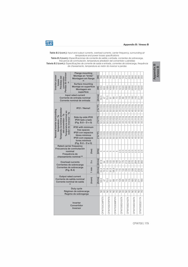
CFW700 | 179
Appendix B / Anexo B
Ap
pen
dix
BA
nexo
B
Table B.3 (cont.): Input and output currents, overload currents, carrier frequency, surrounding air
temperature and power losses specifications
Tabla B.3 (cont.): Especificaciones de corriente de salida y entrada, corrientes de sobrecarga,
frecuencia de conmutación, temperatura alrededor del convertidor y pérdidas
Tabela B.3 (cont.): Especificações de corrente de saída e entrada, correntes de sobrecarga, frequência
de chaveamento, temperatura ao redor do inversor e perdas
InverterConvertidor
Inversor
Duty cycleRégimen de sobrecargaRegime de sobregarga
Output rated currentCorriente de salida nominalCorrente nominal de saída
(1)
Overload currentsCorrientes de sobrecargaCorrentes de sobrecarga
(Fig. B.4)
Rated carrier frequencyFrecuencia de conmutación
nominal Frequência de
chaveamento nominal (2)
Nom
inal
inve
rter
sur
roun
din
g
tem
per
atur
e -
TaTe
mp
erat
u ra
nom
inal
alre
ded
or
del
con
vert
idor
- T
aTe
mp
erat
ura
no
min
al a
o
red
or
do
inve
rso
r -
Ta
Input rated currentCorriente de entrada nominalCorrente nominal de entrada
Inve
rter
po
wer
lo
sses
Pér
did
as d
el
conv
erti
do
rP
erd
as d
o in
vers
or
(3)
IP20 with minimumfree spaces
IP20 con espacios libres mínimos
IP20 com espaçoslivres mínimos
(Fig. B.8 – D ≠ 0)
Side-by-side IP20IP20 lado a lado(Fig. B.8 – D = 0)
IP21 / Nema1
Surface mountingMontaje en superficie
Montagem em superfície
Flange mountingMontaje en “brida”
Montagem em flange(4)
(In
om
)1
min
3 s
(fsw
)
[Arm
s][A
rms]
[Arm
s][k
Hz]
[°C
/°F
][°
C/°
F]
[°C
/°F
][A
rms]
[W]
[W]
CF
W70
0C
58
P5
T4
ND
58
.56
4.4
87.
85
50 (12
2)
50 (12
2)
50 (12
2)
58
.510
50
16
0
HD
47
70.5
94
55
0 (12
2)
50
(12
2)
50
(12
2)
47
80
012
0
CF
W70
0D
70
P5
T4
ND
70.5
77.
610
65
50
(12
2)
50
(12
2)
50
(12
2)
70.5
128
019
0
HD
61
91.5
12
25
50
(12
2)
50
(12
2)
50
(12
2)
61
10
50
16
0
CF
W70
0D
88
P0T4
ND
88
96
.813
25
50
(12
2)
50
(12
2)
50
(12
2)
88
14
80
22
0
HD
73
110
14
65
50 (12
2)
50 (12
2)
50 (12
2)
73
1170
18
0
CF
W70
0E
010
5T4
ND
10
5115
157
2.5
45
(113
)4
5 (113
)4
5 (113
)10
51270
20
0
HD
88
13
2176
2.5
45 (113
)4
5 (113
)4
5 (113
)8
810
20
19
0
CF
W70
0E
0142
T4
ND
142
15
6213
2.5
45
(113
)4
5 (113
)4
5 (113
)142
16
80
210
HD
115
172
23
02.5
45 (113
)4
5 (113
)4
5 (113
)115
12
90
20
0
CF
W70
0E
018
0T4
ND
18
019
8270
2.5
45
(113
)4
5 (113
)4
5 (113
)18
02
05
03
60
HD
142
213
28
42.5
45
(113
)4
5 (113
)4
5 (113
)142
1570
35
0
CF
W70
0E
0211T4
ND
211
23
2316
2.5
45 (113
)4
5 (113
)4
5 (113
)211
23
30
36
0
HD
18
0270
36
02.5
45
(113
)4
5 (113
)4
5 (113
)18
019
40
35
0

180 | CFW700
Appendix B / Anexo B
Ap
pend
ix BA
nexo B
Notes:(1) Rated current considering the switching frequency and surrounding inverter temperature specified in
table, and the environmental conditions specified in the section 3.1.1 - Installation Environmet.
(2) The switching frequency can be automatically reduced to 2.5 kHz, depending on the inverter operation
conditions, if P0350 = 0 or 1.
(3) Losses for rated operation conditions, i.e., for rated output current, frequency, and switching frequency
values.
(4) The dissipated power specified for flange mounting corresponds to the total losses, minus the power
module (IGBT and rectifier) and DC link inductor losses.
Notas: (1) Corriente nominal considerando la frecuencia de conmutación y la temperatura alrededor del convertidor
especificadas en la tabla y las condiciones ambientales especificadas en el ítem 3.1.1 - Condiciones
Ambientales.
(2) La frecuencia de conmutación puede ser reducida automáticamente para 2.5 kHz dependiendo de las
condiciones de operación del convertidor si P0350 = 0 o 1.
(3) Pérdidas para condición nominal de operación, o sea, para valores nominales de corriente de salida,
frecuencia de salida y frecuencia de conmutación.
(4) La potencia disipada especificada para montaje en brida corresponde a las pérdidas totales del
convertidor descontando las pérdidas en los módulos de potencia (IGBT y rectificador) e inductores del
link CC.
Notas: (1) Corrente nominal considerando-se a frequência de chaveamento e temperatura ao redor do inversor
especificadas na tabela e as condições ambientais especificadas no item 3.1.1 - Condições ambientais.
(2) A frequência de chaveamento pode ser reduzida automaticamente para 2.5 kHz dependendo das
condições de operação do inversor se P0350 = 0 ou 1.
(3) Perdas para condição nominal de operação, ou seja, para valores nominais de corrente de saída,
frequência de saída e frequência de chaveamento.
(4) A potência dissipada especificada para montagem em flange corresponde às perdas totais do inversor
descontando as perdas nos módulos de potência (IGBT e retificador) e indutores do link CC.

CFW700 | 181
Appendix B / Anexo B
Ap
pen
dix
BA
nexo
B
Table B.3 presents only two points of the overload curve (activation time of 1 min and 3 s). The complete
information about the IGBTs overload for Normal and Heavy Duty Cycles is presented below. Depending on
the inverter usage conditions (surrounding air temperature, output frequency, possibility or not of reducing
the carrier frequency, etc.) the maximum time for operation of the inverter with overload may be reduced.
En la tabla B.3 fueran presentados solo dos puntos de la curva de sobrecarga (tiempo de actuación de 1 min
y 3 s). Las curvas completas de sobrecarga de los IGBTs para cargas ND y HD son presentadas a seguir.
Dependiendo de las condiciones de operación del convertidor de frecuencia (temperatura ambiente en
las proximidades del convertidor de frecuencia, frecuencia de salida, posibilidad o no de reducción de la
frecuencia de conmutación, etc.) el tiempo máximo para operación del convertidor con sobrecarga puede
ser reducido.
Na tabela B.3 foram apresentados apenas dois pontos da curva de sobrecarga (tempo de atuação de 1 min
e 3 s). As curvas completas de sobrecarga dos IGBTs para cargas ND e HD são apresentadas a seguir.
Dependendo das condições de operação do inversor (temperatura ambiente ao redor do inversor, frequência
de saída, possibilidade ou não de redução da frequência de chaveamento, etc.) o tempo máximo para
operação do inversor com sobrecarga pode ser reduzido.
2.0
1.9
1.8
1.7
1.6
1.5
1.4
1.3
1.2
1.1
1.0
0.9
0 10 20 30 40 50 60 70 80 90 100 110 120
IoInom ND
Δ t (s)
(a) IGBTs overload curve for the Normal Duty (ND) cycle(a) Curva de sobrecarga de los IGBTs para régimen de sobrecarga normal (ND)
(a) Curva de sobrecarga dos IGBTs para regime de sobrecarga normal (ND)
Δ t (s)
2.0
1.9
1.8
1.7
1.6
1.5
1.4
1.3
1.2
1.1
1.0
0 10 20 30 40 50 60 70 80 90 100 110 120
IoInom HD
(b) IGBTs overload curve for the Heavy Duty (HD) cycle(b) Curva de sobrecarga de los IGBTs para régimen de sobrecarga pesada (HD)
(b) Curva de sobrecarga dos IGBTs para regime de sobrecarga pesada (HD)
Figure B.4 (a) and (b): Overload curves for the IGBTsFigure B.4 (a) y (b): Curvas de sobrecarga de los IGBTsFigure B.4 (a) e (b): Curvas de sobrecarga dos IGBTs

182 | CFW700
Appendix B / Anexo B
Ap
pend
ix BA
nexo B
Table B.5: Recommended wiring – use only copper wiring (75 ºC)
Tabla B.5: Cableado recomendado – utilice solamente cableado de cobre (75 °C)
Tabela B.5: Fiação recomendada – ultilize somente fiação de cobre (75 °C)
Fram
eM
ecán
ica
Mec
ânic
a
Po
wer
su
pp
lyTe
nsi
ón
de
alim
enta
ció
nTe
nsã
o d
e al
imen
taçã
o
Term
inal
sTe
rmin
ales
Term
inai
s
Bo
lt (w
ren
ch/s
crew
hea
d t
ype)
Torn
illo
(des
arm
ado
r)T
ipo
de
par
afu
so
Rec
om
men
ded
to
rqu
eTo
rqu
e re
com
end
ado
Wir
e te
rmin
al t
ype
Tip
o d
e te
rmin
al p
ara
cab
le d
e p
ote
nci
aT
ipo
do
ter
min
al p
ara
cab
o
de
po
tên
cia
Ad
dit
ion
al
com
men
tC
om
enta
rio
ad
icio
nal
Co
men
tári
o
adic
ion
alV
rms
N.m
(lb
f.in
)
A
20
0...2
40
R/L
1, S
/L2, T/L
3, U
/T1, V
/T2,
W/T
3,
DC
+,
DC
-, B
R
M4
/slo
tted
an
d P
hill
ips h
ead
(co
mb
)
M4 (fe
nd
a/p
hill
ips)
1.8
(15.6
)P
in t
erm
inal /
Tip
o a
nill
o /
Tip
o ilh
ós
(1)
PE
M4
/Ph
illip
s h
ead
M4
(p
hill
ips)
1.8
(15.6
)R
ing
to
ng
ue t
erm
inal /
Tip
o
oja
les /
Tip
o o
lhal
-
38
0...4
80
R/L
1, S
/L2, T/L
3, U
/T1, V
/T2,
W/T
3,
DC
+,
DC
, B
R
M4
/Po
zid
riv h
ead
M4 (p
ozid
riv)
1.1
(10.0
)
Sp
ad
e t
on
gu
e (fo
rk) te
rmin
al
/ T
ipo
ho
rqu
illa /
Tip
o
forq
uilh
a
(1)
PE
M4
/Ph
illip
s h
ead
M4
(p
hill
ips)
1.7
(15.0
)R
ing
to
ng
ue t
erm
inal /
Tip
o
oja
les /
Tip
o o
lhal
-
B2
00...2
40 /
38
0...4
80
R/L
1, S
/L2, T/L
3, U
/T1, V
/T2,
W/T
3,
DC
+,
DC
-, B
R
M4
/Po
zid
riv h
ead
M4 (p
ozid
riv)
1.2
(10.8
)P
in t
erm
inal /
Tip
o a
nill
o /
Tip
o ilh
ós
(1)
PE
M4
/Ph
illip
s h
ead
M4
(p
hill
ips)
1.7
(15.0
)R
ing
to
ng
ue t
erm
inal /
Tip
o
oja
les /
Tip
o o
lhal
-
C2
00...2
40 /
38
0...4
80
R/L
1, S
/L2, T/L
3, U
/T1, V
/T2,
W/T
3,
DC
+,
DC
-, B
R
M5
/Po
zid
riv h
ead
M5 (p
ozid
riv)
2.7
(24.0
)P
in t
erm
inal /
Tip
o a
nill
o /
Tip
o ilh
ós
(2)
PE
M5
/Ph
illip
s h
ead
3.5
(31.0
)R
ing
to
ng
ue t
erm
inal /
Tip
o
oja
les /
Tip
o o
lhal
-
D
20
0...2
40
R/L
1, S
/L2, T/L
3, U
/T1, V
/T2,
W/T
3,
DC
+,
DC
-, B
R
M6
/slo
tted
head
M6 (fe
nd
a)
5.0
(4
4.2
)P
in t
erm
inal /
Tip
o a
nill
o /
Tip
o ilh
ós
-
PE
M5
/Ph
illip
s h
ead
M5 (p
hill
ips)
3.5
(31.0
)R
ing
to
ng
ue t
erm
inal /
Tip
o
oja
les /
Tip
o o
lhal
-
38
0...4
80
R/L
1, S
/L2, T/L
3, U
/T1, V
/T2,
W/T
3,
DC
+,
DC
-, B
R
M5
/slo
tted
head
M5 (fe
nd
a)
2.9
(24.0
)P
in t
erm
inal /
Tip
o a
nill
o /
Tip
o ilh
ós
-
PE
M5
/Ph
illip
s h
ead
M5 (p
hill
ips)
3.5
(31.0
)R
ing
to
ng
ue t
erm
inal /
Tip
o
oja
les /
Tip
o o
lhal
-
E2
20
-23
0 /
38
0...4
80
R/L
1, S
/L2, T/L
3, U
/T1, V
/
T2,
W/T
3,
DC
L+
, D
CL-
, D
C+
,
DC
-, B
R
M10
(10
5 a
nd
142
A) (h
exag
on
al scre
w)
M8 (18
0 a
nd
211 A
) (h
exag
on
al p
hill
ips s
cre
w)
M10 (10
5 y
142 A
) (to
rnill
o s
exta
vad
o)
M8
(18
0 y
211
A) (to
rnill
o s
exta
vad
o p
hill
ips)
M10 (10
5 e
142 A
) (p
ara
fuso s
exta
vad
o)
M8
(18
0 e
211
A) (p
ara
fuso
sexta
vad
o p
hill
ips)
M8:
15
(13
2.7
5)
M10
: 3
0 (2
65
.5)
Rin
g t
on
gu
e t
erm
inal /
Tip
o
oja
les /
Tip
o o
lhal
-
PE
M5 a
nd
M8 (h
exag
on
al p
hill
ips s
cre
w)
M5 y
M8 (to
rnill
o s
exta
vad
o p
hill
ips)
M5 e
M8 (p
ara
fuso s
exta
vad
o p
hill
ips)
M5:
3.5
(31.0
)
M8:
10
(8
8.5
)
Rin
g t
on
gu
e t
erm
inal /
Tip
o
oja
les /
Tip
o o
lhal
-

CFW700 | 183
Appendix B / Anexo B
Ap
pen
dix
BA
nexo
B
Notes:(1) There is a plastic cover in front of the DC - terminal. It is necessary to break off that cover in order to get
access to this terminal.
(2) There are plastic covers in front of the DC -, DC+ and BR terminals. It is necessary to break off those
covers in order to get access to these terminals.
Notas:(1) Hay una pieza plástica en frente al terminal DC-. Es necesario quebrarla para tener acceso a este
terminal.
(2) Hay piezas plásticas en frente a los bornes DC-, DC+ y BR. Es necesario quebrar estas piezas para
tener acceso a los bornes.
Notas:(1) Há uma peça plástica em frente ao terminal DC-. É preciso quebrá-la para se ter acesso a esse terminal.
(2) Há peças plásticas em frente aos bornes DC-, DC+ e BR. É preciso quebrar estas peças para ter
acesso aos bornes.

184 | CFW700
Appendix B / Anexo B
Ap
pend
ix BA
nexo B
Table B.6: Conducted and radiated emission levels, and additional information
Tabla B.6: Niveles de emisión conducida y irradiada e informaciones adicionales
Tabela B.6: Níveis de emissão conduzida e radiada e informações adicionaisIn
vert
er m
od
el
(wit
h b
uilt
-in
RF
I filt
er)
Mo
del
o d
el c
onv
erti
do
r d
e fr
ecu
enci
a (c
on
filtr
o R
FI i
nte
rno
)M
od
elo
do
inve
rso
r(c
om
filt
ro R
FI i
nte
rno
)
Wit
ho
ut
exte
rnal
RF
I filt
erS
in fi
ltro
RF
I ext
ern
oS
em fi
ltro
RF
I ext
ern
o
Wit
h ex
tern
al R
FI fi
lter
Co
n fil
tro
RF
I ext
ern
oC
om
filt
ro R
FI e
xter
no
Co
nd
uct
ed e
mis
sio
n -
ma
xim
um
mo
tor
cab
le le
ng
thE
mis
ión
con
du
cid
a -
lon
git
ud
má
xim
a d
el
cab
le d
el m
oto
rE
mis
são
co
nd
uzi
da
- co
mp
rim
ento
má
xim
o
do
cab
o d
o m
oto
r
Rad
iate
d
emis
sio
nE
mis
ión
rad
iad
aE
mis
são
ra
dia
da
Ext
ern
al R
FI fi
lter
p
art
nu
mb
er
(man
ufa
ctu
rer:
E
PC
OS
)R
efer
enci
a co
mer
cial
d
el fi
ltro
RF
I ex
tern
o
(fab
rica
nte:
E
PC
OS
)R
efer
ênci
a co
mer
cial
do
filt
ro R
FI
exte
rno
(fab
rica
nte:
E
PC
OS
) (1)
Co
nd
uct
ed e
mis
sio
n -
ma
xim
um
mo
tor
cab
le le
ng
thE
mis
ión
con
du
cid
a -
lon
git
ud
m
áxi
ma
del
cab
le d
el m
oto
rE
mis
são
co
nd
uzi
da
- co
mp
rim
ento
má
xim
o d
o
cab
o d
o m
oto
r
Rad
iate
d e
mis
sio
n -
cate
go
ryE
mis
ión
rad
iad
a -
cate
go
ría
Em
issã
o r
adia
da
- ca
teg
ori
a
Cat
ego
ry C
3C
ateg
orí
a C
3C
ateg
ori
a C
3
Cat
ego
ry C
2C
ateg
orí
a C
2C
ateg
ori
a C
2
Cat
ego
ryC
ateg
orí
aC
ateg
ori
a
Cat
ego
ry C
2C
ateg
orí
a C
2C
ateg
ori
a C
2
Cat
ego
ry C
1C
ateg
orí
a C
1C
ateg
ori
a C
1
Wit
ho
ut
met
allic
ca
bin
etS
in t
able
ro
met
álic
oS
em p
ain
el
met
álic
o
Insi
de
a m
etal
lic
cab
inet
Den
tro
del
tab
lero
m
etál
ico
D
entr
o d
e p
ain
el
met
álic
o (3
)
CF
W70
0A
06
P0
S2...C
3...
10
0 m
7 m
C2
B8
4142-A
16
-R12
275 m
50
mC
2C
2B
84142-B
16
-R10
0 m
(2)
10
0 m
CF
W70
0A
07P
0T2...C
3...
10
0 m
5 m
C2
B8
414
3-G
8-R
110
10
0 m
-C
2C
2B
8414
3-A
8-R
10
55
0 m
(2)
50
m
CF
W70
0A
07P
0S
2...C
3...
10
0 m
7 m
C2
B8
4142-A
16
-R12
275 m
5
0 m
C2
C2
B8
4142-B
16
-R10
0 m
(2)
10
0 m
CF
W70
0A
10
P0
S2...C
3...
10
0 m
7 m
C2
B8
4142-A
30
-R12
275 m
5
0 m
C2
C2
B8
4142-B
25
-R10
0 m
(2)
10
0 m
CF
W70
0A
10
P0T2...C
3...
10
0 m
5 m
C2
B8
414
3-G
20
-R110
10
0 m
-
C2
C2
B8
414
3-A
16
-R10
55
0 m
(2)
50
m
CF
W70
0A
13
P0T2...C
3...
10
0 m
5 m
C2
B8
414
3-G
20
-R110
10
0 m
-C
2C
2B
8414
3-A
16
-R10
55
0 m
(2)
50
m
CF
W70
0A
16
P0T2...C
3...
10
0 m
5 m
C2
B8
414
3-G
20
-R110
10
0 m
-C
2C
2B
8414
3-A
25
-R10
55
0 m
(2)
50
m

CFW700 | 185
Appendix B / Anexo B
Ap
pen
dix
BA
nexo
B
Table B.6 (cont.): Conducted and radiated emission levels, and additional information
Tabla B.6 (cont.): Niveles de emisión conducida y irradiada e informaciones adicionales
Tabela B.6 (cont.): Níveis de emissão conduzida e radiada e informações adicionais
Inve
rter
mo
del
(w
ith
bu
ilt-i
n R
FI fi
lter
)M
od
elo
del
co
nver
tid
or
de
frec
uen
cia
(co
n fil
tro
RF
I in
tern
o)
Mo
del
o d
o in
vers
or
(co
m fi
ltro
RF
I in
tern
o)
Wit
ho
ut
exte
rnal
RF
I filt
erS
in fi
ltro
RF
I ext
ern
oS
em fi
ltro
RF
I ext
ern
o
Wit
h ex
tern
al R
FI fi
lter
Co
n fil
tro
RF
I ext
ern
oC
om
filt
ro R
FI e
xter
no
Co
nd
uct
ed e
mis
sio
n -
ma
xim
um
mo
tor
cab
le le
ng
thE
mis
ión
con
du
cid
a -
lon
git
ud
má
xim
a d
el
cab
le d
el m
oto
rE
mis
são
co
nd
uzi
da
- co
mp
rim
ento
má
xim
o
do
cab
o d
o m
oto
r
Rad
iate
d
emis
sio
nE
mis
ión
rad
iad
aE
mis
são
ra
dia
da
Ext
ern
al R
FI fi
lter
p
art
nu
mb
er
(man
ufa
ctu
rer:
E
PC
OS
)R
efer
enci
a co
mer
cial
d
el fi
ltro
RF
I ex
tern
o
(fab
rica
nte:
E
PC
OS
)R
efer
ênci
a co
mer
cial
do
filt
ro R
FI
exte
rno
(fab
rica
nte:
E
PC
OS
) (1)
Co
nd
uct
ed e
mis
sio
n -
ma
xim
um
mo
tor
cab
le le
ng
thE
mis
ión
con
du
cid
a -
lon
git
ud
m
áxi
ma
del
cab
le d
el m
oto
rE
mis
são
co
nd
uzi
da
- co
mp
rim
ento
má
xim
o d
o
cab
o d
o m
oto
r
Rad
iate
d e
mis
sio
n -
cate
go
ryE
mis
ión
rad
iad
a -
cate
go
ría
Em
issã
o r
adia
da
- ca
teg
ori
a
Cat
ego
ry C
3C
ateg
orí
a C
3C
ateg
ori
a C
3
Cat
ego
ry C
2C
ateg
orí
a C
2C
ateg
ori
a C
2
Cat
ego
ryC
ateg
orí
aC
ateg
ori
a
Cat
ego
ry C
2C
ateg
orí
a C
2C
ateg
ori
a C
2
Cat
ego
ry C
1C
ateg
orí
a C
1C
ateg
ori
a C
1
Wit
ho
ut
met
allic
ca
bin
etS
in t
able
ro
met
álic
oS
em p
ain
el
met
álic
o
Insi
de
a m
etal
lic
cab
inet
Den
tro
del
tab
lero
m
etál
ico
D
entr
o d
e p
ain
el
met
álic
o (3
)
CF
W70
0B
24
P0
T2...C
3...
10
0 m
No
/ N
ão
C3
B8
414
3-A
36
-R10
510
0 m
(2)
10
0 m
C2
C2
CF
W70
0B
28
P0T2...C
3...
10
0 m
No /
Não
C3
B8
414
3-A
36
-R10
510
0 m
(2)
10
0 m
C2
C2
CF
W70
0B
33
P5
T2...C
3...
10
0 m
No /
Não
C3
B8
414
3-A
50
-R10
510
0 m
(2)
10
0 m
C2
C2
CF
W70
0C
45
P0T2...C
3...
10
0 m
No /
Não
C3
B8
414
3-A
50
-R10
510
0 m
(2)
10
0 m
C3
C2
CF
W70
0C
54
P0
T2...C
3...
10
0 m
No
/ N
ão
C3
B8
414
3-A
66
-R10
510
0 m
(2)
10
0 m
C3
C2
CF
W70
0C
70
P0T2...C
3...
10
0 m
No /
Não
C3
B8
414
3-A
90
-R10
510
0 m
(2)
10
0 m
C3
C2
CF
W70
0D
86
P0
T2...C
3...
10
0 m
No
/ N
ão
C3
B8
414
3-A
12
0-R
10
510
0 m
(2)
10
0 m
C3
C2
CF
W70
0D
010
5T2...C
3...
10
0 m
No
/ N
ão
C3
B8
414
3-A
12
0-R
10
510
0 m
(2)
10
0 m
C3
C2
CF
W70
0E
0142
T2...C
3...
10
0 m
-C
3 (6
)B
8414
3B
015
0S
02
010
0 m
--
C2
CF
W70
0E
018
0T2...C
3...
10
0 m
-C
3 (6
)B
8414
3B
018
0S
02
0 (4
)10
0 m
--
C2
CF
W70
0E
0211T2...C
3...
10
0 m
-C
3 (6
)B
8414
3B
025
0S
02
0 (5
)10
0 m
--
C2
CF
W70
0A
03
P6
T4...C
3...
10
0 m
5 m
C2
B8
414
3-G
8-R
110
10
0 m
-C
2C
2B
8414
3-A
8-R
10
55
0 m
(2)
50
m
CF
W70
0A
05
P0T4...C
3...
10
0 m
5 m
C2
B8
414
3-G
8-R
110
10
0 m
-C
2C
2B
8414
3-A
8-R
10
55
0 m
(2)
50
m
CF
W70
0A
07P
0T4...C
3...
10
0 m
5 m
C2
B8
414
3-G
8-R
110
10
0 m
-C
2C
2B
8414
3-A
8-R
10
55
0 m
(2)
50
m

186 | CFW700
Appendix B / Anexo B
Ap
pend
ix BA
nexo B
Table B.6 (cont.): Conducted and radiated emission levels, and additional information
Tabla B.6 (cont.): Niveles de emisión conducida y irradiada e informaciones adicionales
Tabela B.6 (cont.): Níveis de emissão conduzida e radiada e informações adicionaisIn
vert
er m
od
el
(wit
h b
uilt
-in
RF
I filt
er)
Mo
del
o d
el c
onv
erti
do
r d
e fr
ecu
enci
a (c
on
filtr
o R
FI i
nte
rno
)M
od
elo
do
inve
rso
r(c
om
filt
ro R
FI i
nte
rno
)
Wit
ho
ut
exte
rnal
RF
I filt
erS
in fi
ltro
RF
I ext
ern
oS
em fi
ltro
RF
I ext
ern
o
Wit
h ex
tern
al R
FI fi
lter
Co
n fil
tro
RF
I ext
ern
oC
om
filt
ro R
FI e
xter
no
Co
nd
uct
ed e
mis
sio
n -
ma
xim
um
mo
tor
cab
le le
ng
thE
mis
ión
con
du
cid
a -
lon
git
ud
má
xim
a d
el
cab
le d
el m
oto
rE
mis
são
co
nd
uzi
da
- co
mp
rim
ento
má
xim
o
do
cab
o d
o m
oto
r
Rad
iate
d
emis
sio
nE
mis
ión
rad
iad
aE
mis
são
ra
dia
da
Ext
ern
al R
FI fi
lter
p
art
nu
mb
er
(man
ufa
ctu
rer:
E
PC
OS
)R
efer
enci
a co
mer
cial
d
el fi
ltro
RF
I ex
tern
o
(fab
rica
nte:
E
PC
OS
)R
efer
ênci
a co
mer
cial
do
filt
ro R
FI
exte
rno
(fab
rica
nte:
E
PC
OS
) (1)
Co
nd
uct
ed e
mis
sio
n -
ma
xim
um
mo
tor
cab
le le
ng
thE
mis
ión
con
du
cid
a -
lon
git
ud
m
áxi
ma
del
cab
le d
el m
oto
rE
mis
são
co
nd
uzi
da
- co
mp
rim
ento
má
xim
o d
o
cab
o d
o m
oto
r
Rad
iate
d e
mis
sio
n -
cate
go
ryE
mis
ión
rad
iad
a -
cate
go
ría
Em
issã
o r
adia
da
- ca
teg
ori
a
Cat
ego
ry C
3C
ateg
orí
a C
3C
ateg
ori
a C
3
Cat
ego
ry C
2C
ateg
orí
a C
2C
ateg
ori
a C
2
Cat
ego
ryC
ateg
orí
aC
ateg
ori
a
Cat
ego
ry C
2C
ateg
orí
a C
2C
ateg
ori
a C
2
Cat
ego
ry C
1C
ateg
orí
a C
1C
ateg
ori
a C
1
Wit
ho
ut
met
allic
ca
bin
etS
in t
able
ro
met
álic
oS
em p
ain
el
met
álic
o
Insi
de
a m
etal
lic
cab
inet
Den
tro
del
tab
lero
m
etál
ico
D
entr
o d
e p
ain
el
met
álic
o (3
)
CF
W70
0A
10
P0T4...C
3...
10
0 m
5 m
C2
B8
414
3-G
20
-R110
10
0 m
-C
2C
2B
8414
3-A
16
-R10
55
0 m
(2)
50
m
CF
W70
0A
13
P5
T4...C
3...
10
0 m
5 m
C2
B8
414
3-G
20
-R110
10
0 m
-C
2C
2B
8414
3-A
16
-R10
55
0 m
(2)
50
m
CF
W70
0B
17P
0T4...C
3...
10
0 m
No /
Não
C3
B8
414
3-A
25
-R10
510
0 m
(2)
10
0 m
C2
C2
CF
W70
0B
24P
0T4...C
3...
10
0 m
No /
Não
C3
B8
414
3-A
36
-R10
5
10
0 m
(2)
10
0 m
C2
C2
CF
W70
0B
31P
0T4...C
3...
10
0 m
No /
Não
C3
B8
414
3-A
36
-R10
5
10
0 m
(2)
10
0 m
C2
C2
CF
W70
0C
38
P0T4...C
3...
10
0 m
No /
Não
C3
B8
414
3-A
50
-R10
5
10
0 m
(2)
10
0 m
C3
C2
CF
W70
0C
45
P0T4...C
3...
10
0 m
No /
Não
C3
B8
414
3-A
50
-R10
5
10
0 m
(2)
10
0 m
C3
C2
CF
W70
0C
58
P5
T4...C
3...
10
0 m
No
/ N
ão
C3
B8
414
3-A
66
-R10
510
0 m
(2)
10
0 m
C3
C2
CF
W70
0D
70
P5
T4...C
3...
10
0 m
No /
Não
C3
B8
414
3-A
90
-R10
510
0 m
(2)
10
0 m
C3
C2
CF
W70
0D
88
P0
T4...C
3...
10
0 m
No
/ N
ão
C3
B8
414
3-A
12
0-R
10
510
0 m
(2)
10
0 m
C3
C2
CF
W70
0E
010
5T4...C
3...
10
0 m
-C
3 (6
)B
8414
3B
015
0S
02
010
0 m
15
m-
C2
CF
W70
0E
0142
T4...C
3...
10
0 m
-C
3 (6
)B
8414
3B
015
0S
02
010
0 m
15
m-
C2
CF
W70
0E
018
0T4...C
3...
10
0 m
-C
3 (6
)B
8414
3B
018
0S
02
0 (4
)10
0 m
15
m-
C2
CF
W70
0E
0211T4...C
3...
10
0 m
-C
3 (6
)B
8414
3B
025
0S
02
0 (5
)10
0 m
15
m-
C2

CFW700 | 187
Appendix B / Anexo B
Ap
pen
dix
BA
nexo
B
Notes:(1) The external RFI filters presented in the table B.6 have been chosen based on the inverter rated
input current specified for ND (normal duty cycle) application, and 50 °C inverter surrounding ambient
temperature. In order to optimize it, consider the inverter input current and its surrounding air temperature
in the application to define the rated current of the external RFI filter to be used. For further information,
consult EPCOS.
(2) It is possible to use longer length; however, a specific test is required.
(3) Standard cabinet without additional EMC measures. It is possible to meet the C1 category radiated
emission levels by adding EMC accessories to the cabinet. In this case, it is required to perform a specific
test to verify the emission levels.
(4) For 45 °C surrounding inverter and filter temperature, and steady output current greater than 172 Arms,
it is necessary to use the B84143B0250S020 filter.
(5) For 40 °C surrounding inverter and filter temperature, and heavy overload duty cycle (HD, output current
< 180 Arms), it is possible to use the B84143B0180S020 filter.
(6) It is necessary to use a metallic cabinet and a Würth Elektronik WE74270191 toroid per phase at the
inverter input.
Notas:(1) Los filtros RFI externos presentados en la tabla B.6 fueron elegidos con base en la corriente de entrada
nominal del convertidor especificada para aplicación ND (régimen de sobrecarga normal) y temperatura
ambiente alrededor del convertidor de 50 °C. Para optimizar, considerar que la corriente de entrada del
convertidor y la temperatura ambiente alrededor del convertidor en la aplicación para definir la corriente
nominal del filtro RFI externo a utilizarse. Para más informaciones consultar la empresa EPCOS.
(2) Es posible utilizar longitudes mayores, pero es necesario prueba específica.
(3) Tablero estándar sin medidas adicionales de EMC. Puédese atender categoría C1 adicionando
accesorios EMC en el tablero. En este caso débese realizar prueba específica para verificar niveles de
emisión.
(4) Para temperatura alrededor del convertidor y filtro de 45 °C y corriente de salida continua mayor que
172 Arms, es necesario usar el filtro B84143B0250S020.
(5) Para temperatura alrededor del convertidor y filtro de 40 °C y aplicaciones con régimen de sobrecarga
pesada (HD, corriente de salida < 180 Arms), es posible usar el filtro B84143B0180S020.
(6) Es necesario usar el armario metálico y usar un toroide Würth Elektronik WE74270191 por fase en la
entrada del convertidor de frecuencia.
Notas:(1) Os filtros RFI externos apresentados na tabela B.6 foram escolhidos com base na corrente de entrada
nominal do inversor especificada para aplicação ND (regime de sobrecarga normal) e temperatura
ambiente ao redor do inversor de 50 °C. Para otimizar, considerar a corrente de entrada do inversor e a
temperatura ambiente ao redor do inversor na aplicação para definir a corrente nominal do filtro RFI externo
a ser utilizado. Para mais informações consultar a EPCOS.
(2) É possível utilizar comprimentos maiores, porém é necessário teste específico.
(3) Painel padrão sem medidas adicionais de EMC. Pode-se atender categoria C1 adicionando-se
acessórios EMC no painel. Nesse caso deve-se realizar teste específico para verificar níveis de emissão.
(4) Para temperatura ao redor do inversor e filtro de 45 °C e corrente de saída contínua maior que 172
Arms, é necessário usar o filtro B84143B0250S020.
(5) Para temperatura ao redor do inversor e filtro de 40 °C e aplicações com regime de sobrecarga pesada
(HD, corrente de saída < 180 Arms), é possível usar o filtro B84143B0180S020.
(6) É necessário usar painel metálico e usar um toróide Würth Elektronik WE74270191 por fase na entrada
do inversor.

188 | CFW700
Appendix B / Anexo B
Ap
pend
ix BA
nexo B
Figure B.7: Inverter dimensions and net weight (mass)
Figura B.7: Dimensiones del convertidor de frecuencia y su peso líquido (masa)
Figura B.7: Dimensões do inversor e peso líquido (massa)
Size A, B, C, D and E – standard inverter
Tamaños A, B, C, D y E – convertidor estándar
Mecânicas A, B, C, D e E – inversor padrão
Size A, B and C with Nema1 kit
Tamaños A, B y C con kit Nema1
Mecânicas A, B e C com kit Nema1
Size E up to 142 A with Nema1 kit
Tamaños E hasta 142 A con kit Nema1
Mecânica E até 142 A com kit Nema1
Size E 180 and 211 A with Nema1 kit
Tamaños E 180 y 211 A con kit Nema1
Mecânica E 180 e 211 A com kit Nema1
Dimension tolerance: ±1.0 mm (±0.039 in)(1) This value refers to the heaviest weight of the frame size.
Tolerancia de las cotas: ±1.0 mm (±0.039 in)(1) Este valor se refiere al mayor peso para el mismo tamaño.
Tolerância das cotas: ±1.0 mm (±0.039 in)(1) Este valor refere-se ao maior peso da mecânica.
FrameMecánicaMecânica
ModelModelo
A1 B1 C1 D1 E1 F1 G1 H1Inverter weight
Peso convertidorPeso inversor
Conduit kit weightPeso kit electroducto
Peso kit conduite
mm (in)
mm (in)
mm (in)
mm (in)
mm (in)
mm (in)
mm (in)
mm (in)
kg (lb)
kg (lb)
A CFW700A...145
(5.71)
247
(9.73)
227
(8.94)
70
(2.75)
270
(10.61)
305
(12.02)
58.4
(2.30)-
6.3
(13.9) (1)
0.8
(1.8)
B CFW700B...190
(7.46)
293
(11.53)
227
(8.94)
71
(2.78)
316
(12.43)
351
(13.82)
58.5
(2.30)-
10.4
(22.9) (1)
0.9
(2.0)
C CFW700C...220
(8.67)
378
(14.88)
293
(11.52)
136
(5.36)
405
(15.95)
448.1
(17.64)
70.7
(2.78)-
20.5
(45.2) (1)
0.9
(2.0)
D CFW700D...300
(11.81)
504
(19.84)
305
(12.00)
135
(5.32)
550
(21.63)- - -
32.6
(71.8) (1)
-
E
CFW700E0105T4...
CFW700E0142... 335
(13.2)
620
(24.4)
358
(14.1)
168
(6.6)
675
(26.6)
735
(28.94)-
82
(3.23) 65.0
(143.3) (1)
2.12
(4.67)
CFW700E0180...
CFW700E0211...
828.9
(32.63)
111.8
(4.40)
82
(3.23)
4.3
(9.48)
F1
A1
D1
A1
H1
F1
C1A1 C1
F1
H1
G1
H1
A1A1
A1A1
C1
D1D1
C1C1
F1
G1
H1
E1
F1
B1
F1

CFW700 | 189
Appendix B / Anexo B
Ap
pen
dix
BA
nexo
B
Figure B.8 (a) to (c): Mechanical installation data (fixing points and minimum ventilation free spaces)
Figura B.8 (a) a (c): Dados para instalación mecánica (puntos de fijación y espacios libres mínimos para ventilación)
Figura B.8 (a) a (c): Dados para instalação mecânica (pontos de fixação e espaços livres mínimos para ventilação)
Tolerance of d3 and e3 dimensions: +1.0 mm (+0.039 in). Tolerance of the other dimensions: ±1.0 mm (±0.039 in).(1) Recommended torque for fixing the inverter (valid for c2 and c3).
(2) The free spaces for the 142 A / 380-480 V models are the same used for the 180 and 211 A models.
(3) It is possible to mount inverters without the top cover side by side - without lateral free space (D = 0).
Tolerancia de las cotas d3 y e3: +1.0 mm (+0.039 in). Tolerancia de las demás cotas: ±1.0 mm (±0.039 in).(1) Torque recomendado para fijación del convertidor (válido para c2 y c3).
(2) Para el modelo 142 A / 380-480 V los espacios libres son los valores de las distancias de los modelos 180 y 211 A.
(3) Es posible montar convertidores sin la tapa superior lado a lado - sin espacio lateral (D = 0).
Tolerância das cotas d3 e e3: +1.0 mm (+0.039 in). Tolerância das demais cotas: ±1.0 mm (±0.039 in).(1) Torque recomendado para fixação do inversor (válido para c2 e c3).
(2) Para o modelo 142 A / 380-480 V os espaços livres são os valores das distâncias dos modelos 180 e 211 A.
(3) É possível montar inversores sem a tampa superior lado a lado - sem espaçamento lateral (D = 0).
FrameMecánicaMecânica
ModelModelo
a2 b2 c2 a3 b3 c3 d3 e3 A B C DTorque
Par (1)
mm (in) mm (in) M mm (in) mm (in) M mm (in) mm (in) mm (in) mm (in) mm (in) mm (in) N.m (lbf.in)
A CFW700A...115
(4.53)
250
(9.85)M5
130
(5.12)
240
(9.45)M5
135
(5.32)
225
(8.86)
25
(0.98)
25
(0.98)
10
(0.39)
30
(1.18) (3)
5.0
(44)
B CFW700B...150
(5.91)
300
(11.82)M5
175
(6.89)
285
(11.23)M5
179
(7.05)
271
(10.65)
40
(1.57)
45
(1.77)
10
(0.39)
30
(1.18) (3)
5.0
(44)
C CFW700C...150
(5.91)
375
(14.77)M6
195
(7.68)
365
(14.38)M6
205
(8.08)
345
(13.59)
110
(4.33)
130
(5.12)
10
(0.39)
30
(1.18) (3)
8.5
(75)
D CFW700D...200
(7.88)
525
(20.67)M8
275
(10.83)
517
(20.36)M8
285
(11.23)
485
(19.10)
110
(4.33)
130
(5.12)
10
(0.39)
30
(1.18)
20.0
(177)
E
CFW700E0105T4...
CFW700E0142...
200
(7.8)
650
(25.6)M8
275
(10.8)
635
(25)M8
315
(12.40)
615
(24.21)
100
(3.94) (3)
130
(5.12) (2)
20
(0.78)
40
(1.57)
20.0
(177)
CFW700E0180...
CFW700E0211...
200
(7.8)
650
(25.6)M8
275
(10.8)
635
(25)M8
315
(12.40)
615
(24.21)
150
(5.91)
250
(9.84)
20
(0.78)
80
(3.15)
20.0
(177)
(a) Surface mounting
(a) Montaje en superficie
(a) Montagem em superfície
(b) Flange mounting
(b) Montaje en flange
(b) Montagem em flange
Max. 3 mm
(0.12 in)
Air flow
Flujo de aire
Fluxo de ar
Air flow
Flujo de aire
Fluxo de ar
(c) Minimum ventilation free spaces
(c) Espacios libres mínimos para ventilación
(c) Espaços livres mínimos para ventilação
CDAB

190 | CFW700
Appendix B / Anexo B
Ap
pend
ix BA
nexo B
Figure B.9: Inverter dimensions in mm [in] - frame A
Figura B.9: Dimensiones del convertidor de frecuencia en mm [in] - mecánica A
Figura B.9: Dimensões do inversor em mm [in] - mecânica A
48.0
1.89
72.0
2.83
100.0
3.94
145.0
5.71
10.00.39
269.210.60
245.19.65
172.16.78
95.8
3.77
M4 (6
X)
70.2
2.76
156.9
6.18
227.0
8.94
115.0
4.53
250.09.84
115.0
4.53
A B
M5 (4
X)
94.0
3.70
34.71.36
10.00.39
10.80.42
94.9
3.74
100.23.94
196.27.72
R3.0
0.12
9.30.36
R5.8
0.23
8.30.3
29.00.35
R3.0
0.12
8.30.3
24.30.17
AB

CFW700 | 191
Appendix B / Anexo B
Ap
pen
dix
BA
nexo
B
Figure B.10: Inverter dimensions in mm [in] - frame B
Figura B.10: Dimensiones del convertidor de frecuencia en mm [in] - mecánica B
Figura B.10: Dimensões do inversor em mm [in] - mecânica B
315.512.4210.00.39
56.0
2.20
90.0
3.54
130.0
5.12
290.311.43
189.3
7.45
136.5
5.37
214.98.46
M4 (6
X)
70.5
2.77
156.6
6.16
227.0
8.94
150.0
5.91
150.0
5.91
300.011.81A B
M5 (4
X)
88.0
3.46
35.41.399.50.37
10.80.43
135.8
5.35
98.33.87196.17.72
9.00.35
12.8
0.50
R3.0
0.12 10.30.40
R5.8
0.23
12.8
0.505.30.21
R3.0
0.12
AB
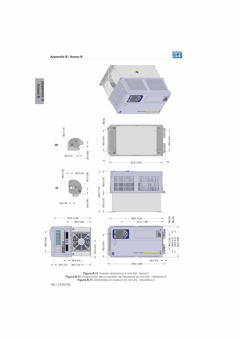
192 | CFW700
Appendix B / Anexo B
Ap
pend
ix BA
nexo B
Figure B.11: Inverter dimensions in mm [in] - frame C
Figura B.11: Dimensiones del convertidor de frecuencia en mm [in] - mecánica C
Figura B.11: Dimensões do inversor em mm [in] - mecânica C
405.015.9415.00.59
85.0
3.35
120.0
4.72
155.0
6.10
220.0
8.66
377.414.86
163.2
6.43
297.111.70
M4 (2
X)M5
(4X)
292.4
11.51
135.5
5.33
156.9
6.18
102.5
4.04
67.02.64
15.00.59
10.70.42
149.8
5.90
169.06.65261.510.30
375.014.76
150.0
5.91
150.0
5.91
BAM6
(4x)
R4.0
0.16
5.00.20
22.5
0.89
B
9.00.35
23.8
0.94
10.00.39
R4.0
0.16
R7.0
0.28
A

CFW700 | 193
Appendix B / Anexo B
Ap
pen
dix
BA
nexo
B
Figure B.12: Inverter dimensions in mm [in] - frame D
Figura B.12: Dimensiones del convertidor de frecuencia en mm [in] - mecánica D
Figura B.12: Dimensões do inversor em mm [in] - mecânica D
549.921.65
212.5
8.37
119.64.71
312.712.31
11.80.47 11.80.47
300.0
11.81
370.614.59
206.9
8.15
134.9
5.31
169.5
6.67
304.6
11.99
200.0
7.87
200.0
7.87
525.020.67A B
M8 (4
X)
142.5
5.61
67.32.65
285.0
11.22
300.0
11.81
181.87.16233.89.20
51.0
(3x)
2.01
28.5
(4x)
1.12
14.00.55
R4.6
0.18
R10.0
0.3915.00.59
40.0
1.57
R4.6
0.18
40.0
1.57
10.00.39
AB

194 | CFW700
Appendix B / Anexo B
Ap
pend
ix BA
nexo B
Figure B.13: Inverter dimensions in mm [in] - frame E
Figura B.13: Dimensiones del convertidor de frecuencia en mm [in] - mecánica E
Figura B.13: Dimensões do inversor em mm [in] - mecânica E
R4.6
[0
.18
]
R4.6
0
[0.1
8]
52.5
[2.0
7]
M8
(4x)
10.0
[0.39]
15.0
[0.59]
14.0 [0.55]
216.0
[8.50]
280.0 [11.02] 675.0
[26.57]
15.1 [0.59]
205.4
[8.09]488.1 [19.22]
619.8 [24.40]
650.0
[25.59]
312.7 [12.31]
15.1 [0.59]
274.5 [10.81]
220.5
[8.7] 67.8
[2.67]
R10
.0
[0.3
9]
52.5
[2.0
7]
314.0
[12.3
6]
242.4
[9.5
5]
35
8.3
[14.1
]2
00
.0
[7.8
7]
20
0.0
[7.8
7]
16
8.0
[6
.61]
19
0.3
[7.4
9]
157.0
[6.1
8]
51.3
[2.0
2] (3
X) K
no
cko
ut
28
.5 [1.1
2] (2
X)
64.0
[2.5
2] (2
X)
212.5
[8
.37
]
33
4.4
[-**
13
.16
]