User´s Guide: BIS CBx fast protokoll EN - BalluffAs noted, CBx commands contain a minimum of six...
108
BIS CBx fast protokoll User's Guide
Transcript of User´s Guide: BIS CBx fast protokoll EN - BalluffAs noted, CBx commands contain a minimum of six...
BIS CBx fast protokoll User's Guide

iv
CONTENTS
REFERENCES .......................................................................................................... vi Conventions ............................................................................................................... vi Reference Documentation ......................................................................................... vi Services and Support ................................................................................................ vii
1 CBX COMMAND PROTOCOL ................................................................................... 1 1.1 Command Protocol Matrix ........................................................................................... 1 1.2 CBx Command Protocol Overview .............................................................................. 1 1.2.1 CBx Command Procedure for Gateway/Hub Interface Modules .................................. 2 1.2.2 CBx Command Procedure for Cobalt Controllers ........................................................ 2 1.3 CBx Command Protocol Packet Structures ................................................................. 2 1.3.1 CBx Command Packet Structure ................................................................................ 2 1.3.2 CBx Response Packet Structure ................................................................................. 3 1.3.3 CBx Multi-Tag Command Packet Structure ................................................................. 6 1.3.4 CBx Multi-Tag Response Packet Structures ............................................................... 9 1.4 Notification Event Messages ..................................................................................... 10 1.5 Error Messages ......................................................................................................... 12 1.5.1 Error Codes .............................................................................................................. 13
2 CBX RFID COMMANDS ........................................................................................... 15 2.1 CBx RFID Command Table ....................................................................................... 15
CBx Command 0x02: LOCK MEMORY BLOCK ........................................................ 18 CBx Command 0x04: FILL TAG ................................................................................ 19 CBx Command 0x05: READ DATA ........................................................................... 20 CBx Command 0x06: WRITE DATA ......................................................................... 21 CBx Command 0x07: READ TAG ID ........................................................................ 22 CBx Command 0x08: TAG SEARCH ........................................................................ 24 CBx Command 0x0C: EXECUTE MACRO ................................................................ 26 CBx Command 0x0D: START CONTINUOUS READ ............................................... 27 CBx Command 0x0E: READ TAG ID AND DATA ..................................................... 30 CBx Command 0x0F: START CONTINUOUS READ TAG ID AND DATA ................ 31 CBx Command 0x10: GET GATEWAY/HUB SOFTWARE VERSION ....................... 34 CBx Command 0x11: GET GATEWAY/HUB NAME ................................................. 35 CBx Command 0x12: GET DIPSWITCH SETTINGS ................................................ 36 CBx Command 0x13: GET NODE STATUS LIST ..................................................... 38 CBx Command 0x14: GET NOTIFICATION MASK ................................................... 40 CBx Command 0x15: GET LAST GATEWAY/HUB ERROR ..................................... 42 CBx Command 0x16: GET GATEWAY/HUB TIME ................................................... 44 CBx Command 0x1A: GET DIGITAL INPUTS ........................................................... 45 CBx Command 0x1B: GET DIGITAL OUTPUTS ....................................................... 47 CBx Command 0x1C: GET SUBNET BAUD RATE ................................................... 49 CBx Command 0x21: SET GATEWAY/HUB NAME .................................................. 50 CBx Command 0x24: SET NOTIFICATION MASK ................................................... 51 CBx Command 0x26: SET GATEWAY/HUB TIME .................................................... 53 CBx Command 0x2A: SET/CLEAR DIGITAL OUTPUTS .......................................... 54 CBx Command 0x2C: SET SUBNET BAUD RATE ................................................... 56 CBx Command 0x30: GET CONTROLLER NAME ................................................... 57 CBx Command 0x33: GET CONTROLLER CONFIGURATION ................................ 58 CBx Command 0x38: GET CONTROLLER INFO ..................................................... 61 CBx Command 0x40: SET CONTROLLER NAME .................................................... 63

v
CBx Command 0x43: SET CONTROLLER CONFIGURATION ................................ 64 CBx Command 0x4E: SET CONTROLLER TIME ..................................................... 67 CBx Command 0x53: INITIALIZE CONTROLLER .................................................... 68 CBx Command 0x54: RESET CONTROLLER .......................................................... 69 CBx Command 0x60: INITIALIZE GATEWAY/HUB .................................................. 70 CBx Command 0x61: RESET GATEWAY/HUB ........................................................ 71 CBx Command 0x62: INITIALIZE ALL NODES ......................................................... 72 CBx Command 0x63: INITIALIZE ALL NODE MACROS ........................................... 73 CBx Command 0x70: START SUBNET .................................................................... 74 CBx Command 0x71: MOVE CONTROLLER (GATEWAY ONLY) ............................ 75 CBx Command 0x79: CLEAR PENDING RESPONSES ........................................... 76 CBx Command 0x92: MULTI-TAG READ ID AND DATA ALL ................................... 77 CBx Command 0x95: MULTI-TAG BLOCK READ ALL ............................................. 79 CBx Command 0x96: MULTI-TAG BLOCK WRITE ALL ........................................... 81 CBx Command 0x97: MULTI-TAG GET INVENTORY .............................................. 83 CBx Command 0x98: MULTI-TAG SEARCH ALL ..................................................... 85 CBx Command 0xA5: MULTI-TAG BLOCK READ BY ID .......................................... 86 CBx Command 0xA6: MULTI-TAG BLOCK WRITE BY ID ........................................ 88 CBx Command 0xC0: SET UHF CONTROLLER CONFIGURATION ........................ 90 CBx Command 0xC1: GET UHF CONTROLLER CONFIGURATION ....................... 92 CBx Command 0xC2: READ EPC CODE ................................................................. 93 CBx Command 0xC3: WRITE EPC CODE ................................................................ 95 CBx Command 0xC4: MULTI-TAG READ EPC CODE ............................................. 96
A REFERENCES ......................................................................................................... 98 EPC Class 1 Gen 2 Tag Memory Structure ............................................................... 98 Command Mapping ................................................................................................... 99
vi
REFERENCES CONVENTIONS This manual uses the following conventions:
“User” or “Operator” refers to anyone using the CBx Protocol software to program an RFID device.
“Device” refers to the Balluff processor units.
“You” refers to the System Administrator or Technical Support person using this manual to program, maintain or troubleshoot an RFID device.
BIS M-41_ , BIS M-62_ and BIS U-62_ processor units are referred to as controllers, or just “the controller ”. BIS M-410 correspond to the old name C-0405 unit BIS M-411 correspond to the old name C-1007 unit BIS M-620-068_ correspond to the old name HF-CNTL-232_ unit BIS M-620-067_ correspond to the old name HF-CNTL-485_ unit BIS M-622-068_ correspond to the old name HF-CNTL-PBS_ unit BIS M-623-071_ correspond to the old name HF-CNTL-DNT_ unit BIS M-626-069_ correspond to the old name HF-CNTL-IND_ unit BIS M-628-075_ correspond to the old name HF-CNTL-PNT_ unit BIS U-620-068_ correspond to the old name UHF-CNTL-232_ unit BIS U-620-067_ correspond to the old name UHF-CNTL-485_ unit BIS U-626-069_ correspond to the old name UHF-CNTL-IND_ unit BIS Z-GW-001-DNT correspond to the old name GWY-01-DNT-01 BIS Z-GW-001-IND correspond to the old name GWY-01-IND-01 BIS Z-GW-001-PBS correspond to the old name GWY-01-PBS-01 BIS Z-GW-001-RS232 correspond to the old name GWY-01-232-01 BIS Z-GW-001-TCP correspond to the old name GWY-01-TCP-01 BIS Z-HB-004-IND correspond to the old name HUB-04-IND-01 BIS Z-HB-004-TCP correspond to the old name HUB-04-TCP-01 REFERENCE DOCUMENTATION
The documentation related to the Gateway, Hub, and the BIS M-41_, BIS M-62_ and BIS U-62_ processor units management is available on the website:
www.balluff.com

vii
SERVICES AND SUPPORT Balluff provides several services as well as technical support through its website. Log on to www.balluff.com and click on the Ulinks U indicated for further information including: • PRODUCTS
Search through the links to arrive at your product page which describes specific Info, Features, Applications, Models, Accessories, and Downloads including:
- Dashboard™: a Windows-based utility program, which allows system testing, monitoring, and configuration using a PC. It provides Serial (RS232 or USB) and Ethernet interface configuration.
- C-Macro Builder™: an easy to use GUI-driven utility for Windows. This software tool allows users with minimal programming experience to “build” their own macro programs (which are stored internally on and executed directly by RFID Controllers).


CBX COMMAND PROTOCOL
1
1 CBX COMMAND PROTOCOL 1.1 COMMAND PROTOCOL MATRIX Balluff RFID products support three basic command protocols: CBx, ABx Fast and ABx Standard. To determine which command protocol to utilize, please refer to the table below, which lists the different RFID devices and indicates the command protocol supported by each. Product CBx ABx Fast ABx Standard BIS M-410-068-001_ X X BIS M-411-068-001_ X X BIS M-620-068-A01-00_ X X BIS U-620-068 X X BIS M-622/623/626_ X BIS U-626-069_ X BIS Z-GW-001_ all models X BIS Z-HB-001_ all models X
Table 1-1: Command Protocol Matrix
NOTE
RS485-based RFID controllers are used in conjunction with Subnet16™ Gateway and Subnet16™ Hub interface modules, which use the CBx Command Protocol.
1.2 CBX COMMAND PROTOCOL OVERVIEW In order to execute RFID commands properly, the RFID device and host computer must be able to communicate using the same language. The language that is used to communicate is referred to as the Command Protocol. The primary command protocol used by TCP/IP and Fieldbus connection-based RFID devices is called "CBx". The CBx Command Protocol incorporates Balluff Multidrop Subnet16™ networking support, which can be used with Industrial Ethernet applications. CBx is based on a double-byte oriented packet structure where commands always contain a minimum of six data “words,” even when one or more parameters are not applicable to the command. CBx does not support the inclusion of a checksum byte, which is supported in the ABx Fast Command Protocol.

CBX PROTOCOL REFERENCE MANUAL
2
1
1.2.1 CBx Command Procedure for Gateway/Hub Interface Modules Commands are initiated by a host computer or Programmable Logic Controller (PLC) and are received by a Subnet16™ Gateway or Subnet16™ Hub Interface Module that is connected to the host, PLC or LAN by standard Ethernet cabling. Commands are delivered from the Gateway/Hub to RFID controllers via ThickNet or ThinNet cabling. When the Gateway/Hub receives a controller-bound command, it distributes the command to the “Node ID” number specified in the command packet. Each 485-based controller connected to the Multidrop Subnet16™ network is assigned an individual Node ID number between 1 and 16. 1.2.2 CBx Command Procedure for Controllers Commands are initiated by a host computer or Programmable Logic Controller (PLC) and are received by a BIS M-41x, BIS M-62x or BIS U-62x- Series Processors that is connected to the host, PLC or LAN by standard Ethernet cabling. Commands are executed directly by the controller when “Node ID 01” is specified in the command packet (for models other than -485, the Node ID will always be 01). 1.3 CBX COMMAND PROTOCOL PACKET STRUCTURES
NOTE
The CBx packet structures described herein are protocol independent and can be implemented the same for all Ethernet or Fieldbus protocols (Ethernet/IP, Modbus TCP, DeviceNet, etc.).
1.3.1 CBx Command Packet Structure As noted, CBx commands contain a minimum of six words (not including the CBx Header and Node ID in the first word). Below is the structure of a standard CBx command packet.

CBX COMMAND PROTOCOL
1
(MSB = Most Significant Byte, LSB = Least Significant Byte) Word # Command Packet Element MSB LSB
00
CBx Header in MSB: 0xFF Node ID in LSB
NOTE: These first two bytes are not required for PLC-based RFID applications (Modbus/TCP, Ethernet/IP)
0xFF <Node ID>
01
Overall Length: 2-byte integer indicating the number of 16-bit “words” in the command packet (not including the previous two bytes: CBx Header and Node ID). Note: this value will always be at least 6, as each command has a minimum of 12-bytes (or 6 words). Overall Length will increase when additional data words are used in the command (for fills, writes, etc.).
0x00
0x06 + (number of
any additional data words)
02 0xAA in MSB Command ID: single-byte value in LSB indicates command to perform
0xAA <Command ID>
03 0x00 in MSB Node ID: LSB value indicates the Node ID number of the device to which the command is intended. See Note below.
0x00 <Node ID>
04
Timeout Value: 2-byte integer representing the length of time allowed for the completion of the command (when applicable). Measured in one-millisecond increments, the Timeout Value can have a value of 0x0001 to 0xFFFE (1 - 65,534 milliseconds).
<Timeout MSB>
<Timeout LSB>
05 Start Address: 2-byte integer indicating the location of tag memory where a read or write operation will begin (when applicable)
<Start MSB> <Start LSB>
06 Block Size: 2-byte integer indicating the number of bytes that are to be read from or written to a tag during the operation (when applicable)
<Size MSB> <Size LSB>
07 Additional Data: (bytes 1 & 2) used to hold 2-bytes of data used for writes and fills (when applicable) <D1> <D2>
08 Additional Data: (bytes 3 & 4) used to hold an additional 2-bytes of data for writes (when applicable) <D3> <D4>
Table 1-2: CBx Command Packet Structure
NOTE
The Node ID value must be 0x20 (Node ID 32) when the command is directed to a Gateway or Hub, 0x01 to 0x10 (Node ID 01 to 16) for a controller in the Subnet16™. When the command is directed to any other controller (i.e. serial point-to-point or Fieldbus slaves), it must be 0x01 (Node ID 01).
1.3.2 CBx Response Packet Structure After executing a command, the controller will generate a host-bound response message. The response message will contain EITHER the results of the attempted command or an error code indicating the reason the operation could not be completed successfully. Below is the structure of a standard CBx response packet.

CBX PROTOCOL REFERENCE MANUAL
4
1
Word # Response Packet Element MSB LSB
00
CBx Header in MSB: 0xFF Node ID Echo in LSB NOTE: These first two bytes will not be returned in the response packet for commands executed by Node 01
0xFF <Node ID Echo>
01
Overall Length: 2-byte integer indicating the number of “words” in the response packet. This value will always be at least 6 words and does not include the previous two bytes: CBx Header and Node ID Echo.
0x00
0x06 + (number of
any additional data words retrieved)
02 0xAA in MSB Command Echo: single-byte LSB value identifies the command that was performed.
0xAA <Command Echo>
03
Instance Counter: in MSB (see description on following page) Node ID Echo: Value in LSB identifies the Node ID of the device that performed the command and/or generated the response.
<Instance Counter>
<Node ID Echo>
04 Month and Day Timestamp <Month> <Day> 05 Hour and Minute Timestamp <Hour> <Minute>
06 Second Timestamp in MSB Additional Data Length: Value in LSB indicates the number of additional bytes retrieved (when applicable)
<Second> <Additional Data Length>
07 Retrieved Data: (bytes 1 & 2) used to hold 2-bytes of retrieved data (when applicable) <B1> <B2>
08 Retrieved Data: (bytes 3 & 4) used to hold an additional 2-bytes of retrieved data (when applicable) <B3> <B4>
Table 1-3: CBx Response Packet Structure Instance Counter The Instance Counter is a one-byte value used to track the number of responses generated by each Node ID. Instance Counter values are stored in the internal RAM of the Gateway/Hub and are incremented by one following each response. If, for example, the controller at Node 01 has generated 10 responses, the Instance Counter value for Node 01 in the Gateway/Hub will read 10 (0x0A). When power is cycled to the Gateway/Hub, the Instance Counter values for all nodes (and for the Gateway/Hub itself) will be reset to zero (0x00). The same is true for all other controller applications (i.e. serial point-to-point or Fieldbus slaves).

CBX COMMAND PROTOCOL
1
CBx Command and Response Example In the example below, Command 0x05 (Read Data) is issued to the controller at Node 01, instructing it to read four bytes of data beginning at tag address 0x0020. The Timeout Value, measured in milliseconds, has been set to two seconds (0x07D0 = 2000 x .001 = 2 seconds) for the completion of this command. Command from Host Word # Command Element MSB LSB
00 CBx Header in MSB: 0xFF Node ID in LSB 0xFF 0x01
01 Overall Length of Command: (in words, not including the previous two bytes ) 0x00 0x06
02 0xAA in MSB Command ID in LSB: (0x05: Read Data) 0xAA 0x05
03 0x00 in MSB Node ID in LSB 0x00 0x01
04 Timeout Value 0x07 0xD0
05 Start Address: (2-byte integer for the starting location of the read operation: 0x0020) 0x00 0x20
06 Block Size: (2-byte integer for the number of bytes to read: 0x0004) 0x00 0x04
Response from Controller Below is an example of the response from the controller at Node 01 after successfully executing the Read Data command (as issued in the previous example). Because this example was performed by the controller at Node 01, the ensuing response will NOT contain the two-byte CBx Header of 0xFF and the Node ID in the first word, as would be the case for all other Node ID responses. Word # Response Element MSB LSB
01 Overall Length of Response: (in words) 0x00 0x08
02 0xAA in MSB Command Echo in LSB: (0x05: Read Data) 0xAA 0x05
03 Instance Counter in MSB Node ID Echo in LSB
<Instance Counter> 0x01
04 Month and Day Timestamp: (March 19th) 0x03 0x13
05 Hour and Minute Timestamp: (10:11: AM) 0x0A 0x0B
06
Seconds Timestamp in MSB: (:36 seconds) Additional Data Length in LSB: (number of bytes retrieved: 0x04)
0x24 0x04
07 Retrieved Data: (bytes 1 & 2) 0x01 0x02 08 Retrieved Data: (bytes 3 & 4) 0x03 0x04
CBX PROTOCOL REFERENCE MANUAL
6
1
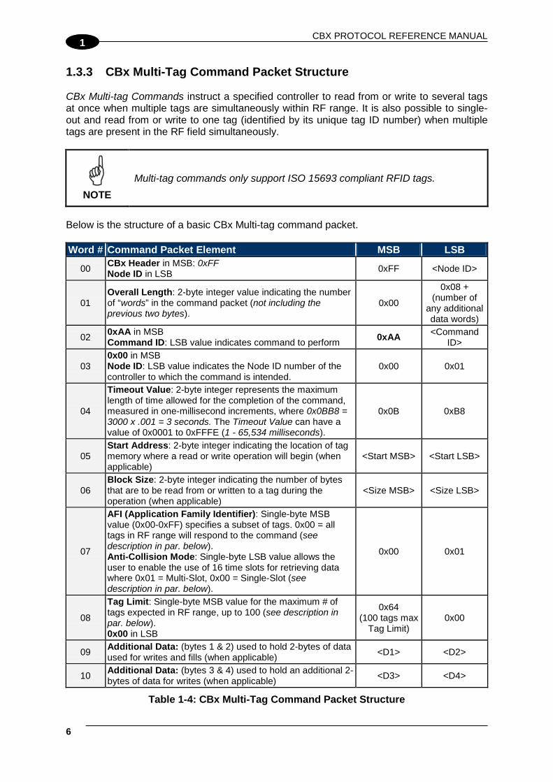
1.3.3 CBx Multi-Tag Command Packet Structure CBx Multi-tag Commands instruct a specified controller to read from or write to several tags at once when multiple tags are simultaneously within RF range. It is also possible to single-out and read from or write to one tag (identified by its unique tag ID number) when multiple tags are present in the RF field simultaneously.
NOTE
Multi-tag commands only support ISO 15693 compliant RFID tags.
Below is the structure of a basic CBx Multi-tag command packet. Word # Command Packet Element MSB LSB
00 CBx Header in MSB: 0xFF Node ID in LSB 0xFF <Node ID>
01 Overall Length: 2-byte integer value indicating the number of “words” in the command packet (not including the previous two bytes).
0x00
0x08 + (number of
any additional data words)
02 0xAA in MSB Command ID: LSB value indicates command to perform 0xAA <Command
ID>
03 0x00 in MSB Node ID: LSB value indicates the Node ID number of the controller to which the command is intended.
0x00 0x01
04
Timeout Value: 2-byte integer represents the maximum length of time allowed for the completion of the command, measured in one-millisecond increments, where 0x0BB8 = 3000 x .001 = 3 seconds. The Timeout Value can have a value of 0x0001 to 0xFFFE (1 - 65,534 milliseconds).
0x0B 0xB8
05 Start Address: 2-byte integer indicating the location of tag memory where a read or write operation will begin (when applicable)
<Start MSB> <Start LSB>
06 Block Size: 2-byte integer indicating the number of bytes that are to be read from or written to a tag during the operation (when applicable)
<Size MSB> <Size LSB>
07
AFI (Application Family Identifier): Single-byte MSB value (0x00-0xFF) specifies a subset of tags. 0x00 = all tags in RF range will respond to the command (see description in par. below). Anti-Collision Mode: Single-byte LSB value allows the user to enable the use of 16 time slots for retrieving data where 0x01 = Multi-Slot, 0x00 = Single-Slot (see description in par. below).
0x00 0x01
08
Tag Limit: Single-byte MSB value for the maximum # of tags expected in RF range, up to 100 (see description in par. below). 0x00 in LSB
0x64 (100 tags max
Tag Limit) 0x00
09 Additional Data: (bytes 1 & 2) used to hold 2-bytes of data used for writes and fills (when applicable) <D1> <D2>
10 Additional Data: (bytes 3 & 4) used to hold an additional 2-bytes of data for writes (when applicable) <D3> <D4>
Table 1-4: CBx Multi-Tag Command Packet Structure

CBX COMMAND PROTOCOL
1
AFI (Application Family Identifier) The AFI parameter is a one-byte value (0x00 – 0xFF) that can be used in multi-tag commands to specify a subset of tags when many are identified simultaneously in RF range. The parameter allows the user to filter tags based on a pre-written value stored at a special location on the tag. For example, if the AFI value is set to one (0x01), only those tags with the pre-written AFI value 0x01 will respond to the given command. When an AFI value of zero (0x00) is entered for this parameter, all tag families within RF range will respond to the command. Anti-Collision Mode Tag collisions in RFID applications occur when numerous passive RFID tags become simultaneously activated (by the RFID controller) and thus reflect their respective signals back to the reader at the same time, such that the controller cannot differentiate between tags. Balluff RFID controllers make use of anti-collision algorithms to enable a single reader/antenna to read more than one tag in the reader's field. The Anti-collision Mode parameter controls the tag-reading algorithm used to achieve the fastest reading speed for the number of tags expected in RF range at any given moment. This parameter helps the reader/antenna avoid data collisions when simultaneously reading multiple tags. The choices for this parameter are one (0x01) for Multi-Slot and zero (0x00) for Single-Slot.
• ONE: Setting this parameter to one (0x01), implements a multi-slot system of 16 time slots. To avoid data collisions when the controller encounters multiple tags simultaneously, data requested from each tag is transferred to the controller only during the time slot that matches a specific pattern in the tag ID number.
• ZERO: Setting this parameter to zero (0x00) utilizes a single time slot under which the requested data from all tags is transferred to the controller as soon as it becomes available. This setting can result in faster tag read performance when only a few tags are expected in the RF field
The Anti-Collision Mode parameter immediately follows the “AFI” parameter in the multi-tag command packet string. Tag Limit The Tag Limit parameter holds a one-byte value that indicates the maximum number of tags expected simultaneously in RF range for the given command operation. This parameter allows users to limit the number of attempted read/write operations the controller will make per execution (users do not have to wait for the Timeout to expire). The Tag Limit value should be set in relation to the maximum number of tags that could possibly be present in the reading field at any one time. Setting a high value increases the number of tags that are expected in the antenna’s RF field. Setting a low value can speed up multi-tag operations when only a small number of tags could be present at any given moment.

CBX PROTOCOL REFERENCE MANUAL
8
1
Setting the proper value is therefore a tradeoff between the number of expected tags in the reading field, and the time required to read/write to them. The permitted values range from one to 100 (0x01 – 0x64). The Tag Limit parameter resides directly after the “Anti-collision Mode” parameter in the command string (when applicable). Timeout Value Multi-tag commands also contain a two-byte Timeout Value parameter that is used to limit the length of time for which the controller will attempt to complete a given operation. It is important to set a realistic Timeout Value that permits enough time for the controller to read/write to all tags specified in the command. Processing multiple-tag operations requires a longer time period than does the execution of single-tag commands. The value is expressed in one-millisecond increments, with a maximum value of 0xFFFE (65,534 milliseconds) or approximately 60 seconds. It is recommended that users allow at least 100 ms per tag for multi-tag read operations and 150 ms per tag for multi-tag writes. Using a Timeout Value that is too short may cause the controller to inadvertently “time out” before the data has been successfully read from or written to all tags in RF range. For time critical applications, the optimal Timeout Value should be obtained through rigorous performance testing. Tag ID / Serial Number There are two multi-tag commands that allow the user to retrieve data from or write data to a single tag (specified by its tag ID number) when numerous tags are concurrently present in the RF field (CBx Command 0xA5 - Multi-Tag Block Read by ID and CBx Command 0xA6 – Multi-Tag Block Write by ID). The tag ID number is a unique, read-only, 64-bit (eight-byte) number stored in tag memory. Targeted tags can be recognized through a previously issued Multi-Tag Get Inventory (0x97) command.

CBX COMMAND PROTOCOL
1
1.3.4 CBx Multi-Tag Response Packet Structures When executing multi-tag commands designed to retrieve information from several tags at once (for example CBx Command 0x92: Multi-Tag Read ID and Data All), the RFID controller will generate separate host-bound response packets for each tag that has been read. Below is the structure of a basic CBx multi-tag response packet generated by the controller at Node 01. CBx Multi-tag Response Packet Structure (One Packet for Each Tag Read) Word # Response Packet Element MSB LSB
01 Overall Length: 2-byte integer indicates the number of “words” in the response packet. 0x00
0x06 + (number of
any additional words
retrieved)
02 0xAA in MSB Command Echo: single-byte value identifies the command that was performed in LSB
0xAA 0x92
03
Instance Counter: 1-byte MSB value indicates number of responses generated by the Node ID identified in the LSB. Node ID Echo: 1-byte value indicates the Node ID of the RFID controller that performed the command.
<IC> 0x01
04 Month and Day Timestamp <Month> <Day> 05 Hour and Minute Timestamp <Hour> <Minute>
06
Second Timestamp in MSB Additional Data Length: single-byte LSB value indicates the number of additional bytes retrieved, includes both Tag ID and Read Data bytes (when applicable)
<Second> <N-bytes>
07 Tag ID bytes 1 and 2: holds the first two bytes of the Tag ID number <ID byte 1> <ID byte 2>
08 Tag ID bytes 3 and 4 <ID byte 3> <ID byte 4> 09 Tag ID bytes 5 and 6 <ID byte 5> <ID byte 6> 10 Tag ID bytes 7 and 8 <ID byte 7> <ID byte 8>
11 Read Data bytes 1 and 2: holds 2 bytes of retrieved data from tag read operations <D01> <D02>
… … … … 18 Read Data bytes 15 and 16 <D15> <D16>
Table 1-5: CBx Multi-Tag Response Packet Structure

CBX PROTOCOL REFERENCE MANUAL
10
1
CBx Multi-Tag Response Final Termination Packet Structure After the RFID controller has issued response packets for each tag identified and/or read, a final termination packet is generated. Below is the structure of a standard CBx multi-tag response final termination packet generated by the controller at Node 01. Word # Final Termination Packet Element MSB LSB
01 Overall Length: 2-byte integer indicates the number of “words” in the packet. 0x00 0x07
02 0xAA in MSB, 0xFF in LSB 0xAA 0xFF
03
Instance Counter: 1-byte value indicates the number of responses generated by the Node ID identified in the LSB (this value is not to be confused with the number of tags read during a single operation) Node ID Echo: 1-byte value indicates the Node ID of the controller that performed the command.
<IC> 0x01
04 Month and Day Timestamp <Month> <Day> 05 Hour and Minute Timestamp <Hour> <Minute>
06
Second Timestamp in MSB Additional Data Length: Single-byte LSB value indicates the number of additional bytes retrieved (value will usually = 2, for Number of Tags Read/Written and Status)
<Second> 0x02
07
Number of Tags Read/Written in MSB, identifies the number of tags read from or written to during the operation Status in LSB (0x00 = operation completed successfully, 0x07 = Read Tag ID failed / Tag Not Found)
<N-tags> 0x00
Table 1-6: CBx Multi-Tag Response Final Termination Packet Structure 1.4 NOTIFICATION EVENT MESSAGES Notification Messages are small host-bound informational packets of data that are issued by a Gateway/Hub when a specified Notification Event occurs within the Gateway/Hub or on the Subnet16™ network. The Gateway/Hub stores 9 different Notification Messages internally. The Hub stores an additional 4 Notification Messages relative to its Inputs/Outputs. See the Notification Message Table below.

CBX COMMAND PROTOCOL
1
Notification Message Table The following table lists the Notification Messages, their bit mask values and contains a description of the Notification Event that can be set to trigger the notification.
Bit Notification Message Notification Event Description 1 CONTROLLER IS HEALTHY Sent whenever the status of a controller changes to
‘Healthy’ 2 CONTROLLER HAS PROBLEM Sent whenever a controller is marked ‘Has Problem’ 3 CONTROLLER STOPPED
RESPONDING Sent whenever a controller is marked ‘Stopped Responding’
4 CONTROLLER DEACTIVATED Sent whenever a controller is deactivated (is marked ‘Inactive’)
5 CONTROLLER MISSED POLL Sent whenever a controller misses a poll 6 CONTROLLER ADDRESS
CONFLICT Sent whenever the Gateway/Hub detects a Node ID conflict
7 CONTROLLER CONFIGURATION FAILURE
Sent whenever the Gateway/Hub fails to configure a controller
8 TAG PRESENT AT NODE * Sent whenever a tag is first recognized in the RF field of the specified node
9 TAG NOT PRESENT AT NODE * Sent whenever a tag is no longer recognized within or has exited the RF field of the specified node
10 INPUT SET (Hub only) Sent when one of the Hub's four Inputs has been set 11 INPUT CLEARED (Hub only) Sent when one of the Hub's four Inputs has been
cleared 12 OUTPUT SET (Hub only) Sent when one of the Hub's four Outputs has been set 13 OUTPUT CLEARED (Hub only) Sent when one of the Hub's four Outputs has been
cleared
Table 1-7: Notification Message Table * - Tag Presence must be enabled on the RFID controller.
NOTE
The Gateway only supports Notification Messages 1 – 9. Notification Messages 10 – 13 pertain to the status of the Hub’s Digital Inputs and Outputs.
Notification Messages are enabled or disabled by setting or clearing the corresponding bit within the 16-bit Notification Mask (see Command 0x24). If the bit is set, the corresponding Notification Message will be generated when the specified event occurs. When a Notification Message is enabled and its corresponding Notification Event occurs, the Notification Message will be generated by the Gateway/Hub and will be written to the Node Output Page of the affected Subnet Node (i.e., the Node ID that triggered the notification). See Command Mapping in the appendix for more details. Triggered Notification Messages are provided immediately to the host.
CBX PROTOCOL REFERENCE MANUAL
12
1
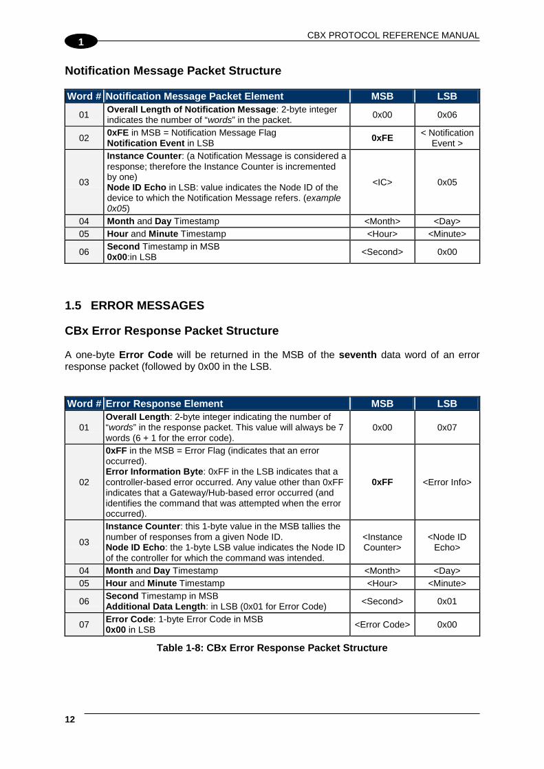
Notification Message Packet Structure Word # Notification Message Packet Element MSB LSB
01 Overall Length of Notification Message: 2-byte integer indicates the number of “words” in the packet. 0x00 0x06
02 0xFE in MSB = Notification Message Flag Notification Event in LSB 0xFE < Notification
Event >
03
Instance Counter: (a Notification Message is considered a response; therefore the Instance Counter is incremented by one) Node ID Echo in LSB: value indicates the Node ID of the device to which the Notification Message refers. (example 0x05)
<IC> 0x05
04 Month and Day Timestamp <Month> <Day> 05 Hour and Minute Timestamp <Hour> <Minute>
06 Second Timestamp in MSB 0x00:in LSB <Second> 0x00
1.5 ERROR MESSAGES CBx Error Response Packet Structure A one-byte Error Code will be returned in the MSB of the seventh data word of an error response packet (followed by 0x00 in the LSB.
Word # Error Response Element MSB LSB
01 Overall Length: 2-byte integer indicating the number of “words” in the response packet. This value will always be 7 words (6 + 1 for the error code).
0x00 0x07
02
0xFF in the MSB = Error Flag (indicates that an error occurred). Error Information Byte: 0xFF in the LSB indicates that a controller-based error occurred. Any value other than 0xFF indicates that a Gateway/Hub-based error occurred (and identifies the command that was attempted when the error occurred).
0xFF <Error Info>
03
Instance Counter: this 1-byte value in the MSB tallies the number of responses from a given Node ID. Node ID Echo: the 1-byte LSB value indicates the Node ID of the controller for which the command was intended.
<Instance Counter>
<Node ID Echo>
04 Month and Day Timestamp <Month> <Day> 05 Hour and Minute Timestamp <Hour> <Minute>
06 Second Timestamp in MSB Additional Data Length: in LSB (0x01 for Error Code) <Second> 0x01
07 Error Code: 1-byte Error Code in MSB 0x00 in LSB <Error Code> 0x00
Table 1-8: CBx Error Response Packet Structure

CBX COMMAND PROTOCOL
1
Error Response Example Below is an example of a CBx Error Response for Error Code 0x07 (Tag Not Found). Error Response Parameter MSB LSB 0x00 in MSB Overall Length of Response in LSB (in words)
0x00 0x07
Error Flag in MSB. Error Information Byte in LSB
0xFF 0xFF
Instance Counter in MSB Node ID Echo in LSB
0x00 0x01
Month and Day Timestamp:(March 19th) 0x03 0x13 Hour and Minute Timestamp: (10:11: AM) 0x0A 0x0B Seconds Timestamp in MSB: (:36 seconds). Additional Data Length in LSB: (0x01 for Error Code)
0x24 0x01
Error Code in MSB (0x07 = Tag Not Found) 0x00 in LSB
0x07 0x00
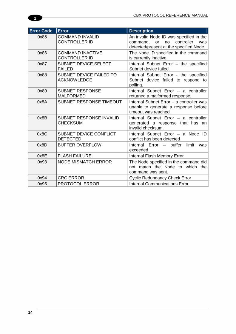
1.5.1 Error Codes Error Code Error Description
0x02 LOCK TAG BLOCK FAILED Lock Tag Block Operation Failed 0x04 FILL TAG FAILED Fill Operation Failed 0x05 READ DATA FAILED Read Data Command Failed 0x06 WRITE DATA FAILED Write Data Command Failed 0x07 READ TAG ID / TAG SEARCH
FAILED Read Tag ID / Tag Search Command Failed (Tag Not Found)
0x21 INVALID SYNTAX Command Contained a Syntax Error 0x23 INVALID TAG TYPE Invalid or Unsupported Tag Type 0x30 INTERNAL CONTROLLER
ERROR Generic Internal Controller Error
0x31 INVALID CONTROLLER TYPE Invalid Controller Type (when Setting Configuration)
0x32 INVALID PROGRAMMING ADDRESS
Invalid Tag Programming Address Specified in the Command
0x35 INVALID RESET Invalid Hardware Reset 0x36 SET CONFIGURATION ERROR Controller Configuration not Written 0x37 GET CONFIGURATION ERROR Controller Configuration not Read 0x80 UNKNOWN GATEWAY/HUB
ERROR Generic Interface Module Error – an error occurred, but the Gateway/Hub could not determine the error code.
0x81 COMMAND MALFORMED Generic Command Syntax Error 0x83 COMMAND INVALID OPCODE Invalid Command ID Number specified
in the command. 0x84 COMMAND INVALID
PARAMETER A parameter specified in the command was invalid.
CBX PROTOCOL REFERENCE MANUAL
14
1
Error Code Error Description 0x85 COMMAND INVALID
CONTROLLER ID An invalid Node ID was specified in the command, or no controller was detected/present at the specified Node.
0x86 COMMAND INACTIVE CONTROLLER ID
The Node ID specified in the command is currently inactive.
0x87 SUBNET DEVICE SELECT FAILED
Internal Subnet Error – the specified Subnet device failed.
0x88 SUBNET DEVICE FAILED TO ACKNOWLEDGE
Internal Subnet Error - the specified Subnet device failed to respond to polling.
0x89 SUBNET RESPONSE MALFORMED
Internal Subnet Error – a controller returned a malformed response.
0x8A SUBNET RESPONSE TIMEOUT Internal Subnet Error – a controller was unable to generate a response before timeout was reached.
0x8B SUBNET RESPONSE INVALID CHECKSUM
Internal Subnet Error – a controller generated a response that has an invalid checksum.
0x8C SUBNET DEVICE CONFLICT DETECTED
Internal Subnet Error – a Node ID conflict has been detected
0x8D BUFFER OVERFLOW Internal Error – buffer limit was exceeded
0x8E FLASH FAILURE Internal Flash Memory Error 0x93 NODE MISMATCH ERROR The Node specified in the command did
not match the Node to which the command was sent.
0x94 CRC ERROR Cyclic Redundancy Check Error 0x95 PROTOCOL ERROR Internal Communications Error

CBX RFID COMMANDS
2
2 CBX RFID COMMANDS 2.1 CBX RFID COMMAND TABLE Command ID Command Name Description
RFID Tag Commands 0x02 L o c k M e m o r y B l o c k Write protects a block of tag memory
0x04 F i l l T a g Writes a specified data byte value to all defined tag addresses
0x05 R e a d D a t a Reads a specified length of data from a contiguous (sequential) area of tag memory
0x06 W r i t e D a t a Writes a specified number of bytes to a contiguous area of tag memory
0x07 R e a d T a g I D Reads a tag’s unique tag ID number
0x08 T a g S e a r c h Instructs the controller to search for a tag in its RF field
0x0C E x e c u t e M a c r o Instructs the controller to execute one of its eight possible macros
0x0D S t a r t C o n t i n u o u s R e a d Instructs the controller to start or stop Continuous Read mode.
0x0E R e a d T a g I D a n d D a t a Reads a tag’s ID and the requested number of bytes from tag memory
0x0F S t a r t C o n t i n u o u s R e a d T a g I D a n d D a t a
Places the controller into (or out of) Continuous Read mode and (when evoked) will retrieve a tag’s ID.
0xC2 R e a d E P C C o d e Reads the 12-byte EPC memory area of an EPC Class 1 Gen 2 tag
0xC3 W r i t e E P C C o d e Writes the 12-byte EPC memory area of an EPC Class 1 Gen 2 tag
Controller Commands
0x30 G e t C o n t r o l l e r N a m e Retrieves the controller’s user-defined name
0x33 G e t C o n t r o l l e r C o n f i g u r a t i o n
Retrieves the controller’s configuration settings
0x38 G e t C o n t r o l l e r I n f o Retrieves hardware, firmware and serial number information from the controller
0x40 S e t C o n t r o l l e r N a m e Used to set (create or modify) the user-defined name for the controller
0x43 S e t C o n t r o l l e r C o n f i g u r a t i o n
Used to set (configure or modify) the controller’s configuration parameters and settings
0x4E S e t C o n t r o l l e r T i m e Used to set the time for the controller
0x53 I n i t i a l i z e C o n t r o l l e r Removes all configuration settings stored for the controller
0x54 R e s e t C o n t r o l l e r Resets power to the controller

CBX PROTOCOL REFERENCE MANUAL
16
2
Command ID Command Name Description Additional UHF-Series Controller Commands
0xC0 S e t U H F C o n t r o l l e r C o n f i g u r a t i o n
Used to set (configure or modify) additional UHF controller configuration parameters
0xC1 G e t C o n t r o l l e r C o n f i g u r a t i o n
Retrieves the UHF controller’s additional configuration parameter settings
I/O Commands
0x1A G e t D i g i t a l I n p u t s Retrieves the status of the RFID Controller or Hub’s digital input(s)
0x1B G e t D i g i t a l O u t p u t s Retrieve the status of the RFID Controller or Hub’s digital outputs
0x2A S e t / C l e a r D i g i t a l O u t p u t s Used to set and/or clear any or all of the RFID Controller or Hub’s digital outputs
Gateway/Hub Subnet Commands
0x10 G e t G a t e w a y / H u b S o f t w a r e V e r s i o n
Retrieves the version number of the firmware code installed on the Gateway/Hub
0x11 G e t G a t e w a y / H u b N a m e Retrieves the Gateway/Hub’s user-defined ASCII name
0x12 G e t D i p s w i t c h S e t t i n g s Retrieves the status of the Gateway/Hub configuration dipswitches
0x13 G e t N o d e S t a t u s L i s t Retrieves the operational status of the Gateway/Hub Subnet Nodes
0x14 G e t N o t i f i c a t i o n M a s k
Retrieves the user-defined 16-bit “Notification Mask” that determines for which events the Gateway/Hub notifies the host PC
0x15 G e t L a s t G a t e w a y / H u b E r r o r
Retrieves information from the Gateway/Hub regarding the last or most recent error that was experienced
0x16 G e t G a t e w a y / H u b T i m e Retrieves the current date and time as set internally on the Gateway/Hub
0x1C G e t S u b n e t B a u d R a t e Retrieves the baud rate of the Subnet network
0x21 S e t G a t e w a y / H u b N a m e Writes to flash memory, a user-defined “friendly” name for the Gateway/Hub
0x24 S e t N o t i f i c a t i o n M a s k Used to customize or modify the Gateway/Hub’s 16-bit Notification Mask
0x26 S e t G a t e w a y / H u b T i m e Used to set the Gateway/Hub’s internal clock and calendar
0x2C S e t S u b n e t B a u d R a t e Used to modify and store changes to the Subnet network baud rate
0x60 I n i t i a l i z e G a t e w a y / H u b Clears all Subnet Node configuration information stored in the Gateway/Hub’s flash memory
0x61 R e s e t G a t e w a y / H u b Performs an electrical reset of the Gateway/Hub

CBX RFID COMMANDS
2
Command ID Command Name Description
0x62 I n i t i a l i z e A l l N o d e s Removes all stored configuration information for all nodes and reconfigures them to factory defaults
0x63 I n i t i a l i z e A l l N o d e M a c r o s Removes all stored macros from all nodes
0x70 S t a r t S u b n e t Instructs the Gateway/Hub to begin “polling” the Subnet network
0x71 M o v e C o n t r o l l e r ( G a t e w a y O n l y )
Used to move all stored configuration data for a particular Node ID to another specified Node ID (Gateway only)
0x79 C l e a r P e n d i n g R e s p o n s e Deletes all pending or buffered responses in the Gateway/Hub and resets all Instance Counters to zero
Multi-Tag RFID Commands
0x92 M u l t i - T a g R e a d I D a n d D a t a A l l
Retrieves the tag ID number and a contiguous segment of data from all RFID tags in range
0x95 M u l t i - T a g B l o c k R e a d A l l Retrieves a contiguous segment of data from all RFID tags in range
0x96 M u l t i - T a g B l o c k W r i t e A l l Writes a contiguous segment of data to all RFID tags in range
0x97 M u l t i - T a g G e t I n v e n t o r y Retrieves the tag ID number from all RFID tags found in range
0x98 M u l t i - T a g S e a r c h A l l Checks for the presence of RFID tags in RF range and returns only the number of tags found
0xA5 Mul t i -Tag Block Read by ID Reads a contiguous segment of data from a specific RFID tag identified by its tag ID
0xA6 Mul t i -Tag Block W ri te by ID Writes a contiguous segment of data to a specific RFID tag identified by its tag ID
0xC4 M u l t i - T a g R e a d E P C C o d e Reads the 12-byte EPC memory area of all EPC Class 1 Gen 2 tags found in range
Table 2-1: CBx RFID Command Table

CBX PROTOCOL REFERENCE MANUAL
18
2
CBX COMMAND 0X02: LOCK MEMORY BLOCK Command 0x02 - Description The Lock Memory Block Command allows the user to write protect or lock a block of tag memory to prevent data from being overwritten. The Starting Block parameter specifies the first block of tag memory addresses to be locked. The Number of Blocks parameter specifies the number of blocks to lock, (1 ~ N). Depending on the architecture of the tag used, a “block” can be either 4-bytes or 8-bytes. Users must know the memory architecture and block size of their tag before using this command. This command only supports ISO 15693 compliant RFID tags.
CAUTION
Extreme caution should be taken when using this command. Once a block of tag memory is locked, it cannot be unlocked and all data written to the block is permanent.
Command 0x02 – CBx Example This example instructs the controller at Node 01 to lock two blocks of tag memory, beginning at block address 0x00 (the first available block). A Timeout Value of two seconds (0x07D0 = 2000 x one-millisecond increments) is set for the completion of this command. Command from Host Parameter Field MSB LSB CBx Header in MSB, Node ID in LSB 0xFF 0x01 Overall Length of Command (in words) 0x00 0x06 0xAA in MSB, Command ID in LSB: (0x02) 0xAA 0x02 0x00 in MSB, Node ID in LSB 0x00 0x01 Timeout Value 0x07 0xD0 Starting Block: (MSB always = 0x00) 0x00 0x00 Number of Blocks: (MSB always = 0x00) 0x00 0x02
Response from Controller Parameter Field MSB LSB Overall Length of Response (in words) 0x00 0x06 0xAA in MSB, Command Echo in LSB (0x02) 0xAA 0x04 Instance Counter in MSB, Node ID Echo in LSB <IC> 0x01 Month and Day Timestamp: (March 19th) 0x03 0x13 Hour and Minute Timestamp: (10:11: AM) 0x0A 0x0B Seconds Timestamp in MSB: (:36 seconds) 0x00 in LSB 0x24 0x00

CBX RFID COMMANDS
2
CBX COMMAND 0X04: FILL TAG Command 0x04 - Description The Fill Tag Command instructs the specified RFID controller to fill multiple contiguous addresses of an RFID tag with a single byte value. This command is commonly used to clear sequential segments of tag memory by writing the one-byte value repeatedly across a specified range of tag addresses. This command requires one Data Byte Value, a Start Address and a Fill Length. It will then proceed to fill the tag with the Data Byte Value, for the specified Fill Length (number of consecutive bytes), beginning at the Start Address. When the Start Address is set to zero (0x0000), the fill will begin at the first available byte of tag memory. When the Fill Length is set to zero (0x0000), the controller will write fill data from the Start Address to the end of the tag’s memory. If the Fill Length value extends beyond the last byte in the tag, the controller will return an error.
NOTE
The “Fill Length” in this command represents the number of bytes to fill on the tag, not the length of the ‘Data Byte Value’ provided in the command, which is always one byte.
Command 0x04 - CBx Example This example instructs the controller at Node 01 to fill an entire tag with the ASCII character 'A' (Data Byte Value 0x41) starting at the beginning of the tag (Start Address 0x0000). A Timeout Value of 2 seconds (0x07D0 = 2000 x one-millisecond increments) is set for the completion of the command. Command from Host Parameter Field MSB LSB CBx Header in MSB, Node ID in LSB 0xFF 0x01 Overall Length of Command (in words) 0x00 0x07 0xAA in MSB, Command ID in LSB: (0x04) 0xAA 0x04 0x00 in MSB, Node ID in LSB 0x00 0x01 Timeout Value 0x07 0xD0 Start Address 0x00 0x00 Fill Length 0x00 0x00 Data Byte Value in MSB (A = 0x41), 0x00 in LSB 0x41 <A> 0x00
Response from Controller Parameter Field MSB LSB Overall Length of Response (in words) 0x00 0x06 0xAA in MSB, Command Echo in LSB (0x04) 0xAA 0x04 Instance Counter in MSB, Node ID Echo in LSB <IC> 0x01 Month and Day Timestamp: (March 19th) 0x03 0x13 Hour and Minute Timestamp: (10:11: AM) 0x0A 0x0B Seconds Timestamp in MSB: (:36 seconds) 0x00 in LSB 0x24 0x00

CBX PROTOCOL REFERENCE MANUAL
20
2
CBX COMMAND 0X05: READ DATA Command 0x05 - Description The Read Data Command instructs the controller to retrieve a specific number of bytes of data from a contiguous (sequential) area of an RFID tag’s memory. When the Start Address is set to zero (0x0000), the controller will start reading at the beginning (or first accessible byte) of the tag. The minimum Block Size is one byte, the maximum Block Size for read operations is 1024 bytes or the entire read/write address space of the tag (whichever is less). If the Block Size exceeds the last available tag address, the controller will return an error code. Command 0x05 - CBx Example This example instructs the controller at Node 01 to read four bytes of data from a tag starting at address 0x0001. A Timeout Value of 2 seconds (0x07D0 = 2000 x one-millisecond increments) is set for the completion of the command. Command from Host Parameter Field MSB LSB CBx Header in MSB, Node ID in LSB 0xFF 0x01 Overall Length of Command (in words) 0x00 0x06 0xAA in MSB. Command ID in LSB (0x05) 0xAA 0x05 0x00 in MSB. Node ID in LSB 0x00 0x01 Timeout Value 0x07 0xD0 Start Address 0x00 0x01 Block Size 0x00 0x04
Response from Controller Parameter Field MSB LSB Overall Length of Response (in words) 0x00 0x08 0xAA in MSB. Command Echo in LSB 0xAA 0x05 Instance Counter in MSB. Node ID Echo in LSB <IC> 0x01 Month and Day Timestamp:(March 19th) 0x03 0x13 Hour and Minute Timestamp: (10:11: AM) 0x0A 0x0B Seconds Timestamp in MSB: (:36 seconds). Additional Data Length in LSB: (0x04)
0x24 0x04
Read Data (bytes 1 and 2) 0x01 0x02 Read Data (bytes 3 and 4) 0x03 0x04

CBX RFID COMMANDS
2
CBX COMMAND 0X06: WRITE DATA Command 0x06 - Description The Write Data Command instructs the controller to write specified information to an RFID tag. This command is used to store segments of data in contiguous tag memory locations. It is capable of transferring up to 100 bytes of data from the host to the tag with one command. When the Start Address is set to zero (0x0000), the controller will begin writing to the first available byte of tag memory. The shortest possible Block Size is one byte, the maximum Block Size for write operations is 1024 bytes or the entire read/write address space of the tag (whichever is less). If the Block Size exceeds the last available tag address, the controller will return an error code. Command 0x06 - CBx Example This example instructs the controller at Node 01 to write the five ASCII characters H, E, L, L, O (Data Byte Values: 0x48, 0x45, 0x4C, 0x4C and 0x4F) to a tag starting at address 0x000. A Timeout Value of 2 seconds (0x07D0 = 2000 x one-millisecond increments) is set for the completion of this command. Command from Host Parameter Field MSB LSB CBx Header in MSB, Node ID in LSB 0xFF 0x01 Overall Length of Command (in words) 0x00 0x09 0xAA in MSB. Command ID in LSB (0x06) 0xAA 0x06 0x00 in MSB. Node ID in LSB 0x00 0x01 Timeout Value (measured in ms) 0x07 0xD0 Start Address 0x00 0x00 Block Size (in bytes) 0x00 0x05 Write Data (bytes 1 and 2) 0x48 <H> 0x45 <E> Write Data (bytes 3 and 4) 0x4C <L> 0x4C <L> Write Data (byte 5) in MSB. 0x00 in LSB 0x4F <O> 0x00
Response from Controller Parameter Field MSB LSB Overall Length of Response (in words) 0x00 0x06 0xAA in MSB. Command Echo in LSB 0xAA 0x06 Instance Counter in MSB. Node ID Echo in LSB <IC> 0x01 Month and Day Timestamp: (March 19th) 0x03 0x13 Hour and Minute Timestamp: (10:11: AM) 0x0A 0x0B Seconds Timestamp in MSB (:36 seconds). 0x00 in LSB 0x24 0x00

CBX PROTOCOL REFERENCE MANUAL
22
2
CBX COMMAND 0X07: READ TAG ID Command 0x07 - Description The Read Tag ID Command instructs the RFID controller to locate a tag in range and retrieve its unique tag identification number. If a tag is not located before the Timeout Value expires, an error will be returned. RFID tags are assigned a unique tag ID number during the manufacturing process. After a tag ID number has been assigned to a tag, the value cannot be altered and is not considered part of the available read/write memory space of the tag. • ISO 14443 compliant tags receive a 4-byte tag ID number. By using just four bytes, tag
manufacturers can generate over 4.2 billion possible ISO 14443 compliant tag ID numbers.
• ISO 15693 compliant tags are given an 8-byte tag ID number. When using eight bytes, manufacturers can generate over 280 trillion possible tag ID numbers.
Command 0x07 - CBx Example This example instructs the controller at Node 01 to retrieve a tag’s ID, which, in this example, is the eight-byte value E0040100002E16AD. A Timeout Value of 2 seconds (0x07D0 = 2000 x one-millisecond increments) is set for the completion of the command. Command from Host Parameter Field MSB LSB CBx Header in MSB, Node ID in LSB 0xFF 0x01 Overall Length of Command (in words) 0x00 0x06 0xAA in MSB. Command ID in LSB (0x07) 0xAA 0x07 0x00 in MSB. Node ID in LSB 0x00 0x01 Timeout Value 0x07 0xD0 Not Used (0x00, 0x00)* 0x00 0x00 Not Used (0x00, 0x00)* 0x00 0x00
NOTE
Even when one or more command parameters are not used in a particular command, the parameter’s two bytes must still be accounted for in the Overall Length. Include all “zeroes” for these bytes (0x00, 0x00).

CBX RFID COMMANDS
2
Response from Controller (Tag Found) Parameter Field MSB LSB Overall Length of Response (in words) 0x00 0x0A 0xAA in MSB, Command Echo in LSB 0xAA 0x07 Instance Counter in MSB, Node ID Echo in LSB <IC> 0x01 Month and Day Timestamp: (March 19th) 0x03 0x13 Hour and Minute Timestamp: (10:11: AM) 0x0A 0x0B Seconds Timestamp in MSB: (:36 seconds). Additional Data Length in LSB: (0x08)
0x24 0x08
Tag ID (bytes 1 & 2) 0xE0 0x04
Tag ID (bytes 3 & 4) 0x01 0x00 Tag ID (bytes 5 & 6) 0x00 0x2E Tag ID (bytes 7 & 8) 0x16 0xAD
Response from Controller (Tag Not Found) Parameter Field MSB LSB Overall Length of Response (in words) 0x00 0x07 Error Flag in MSB = 0xFF. Error Information Byte in LSB. 0xFF in the LSB indicates that a controller-based error occurred. Any value other than 0xFF indicates that a Gateway or Hub-based error occurred (and identifies the command that was attempted when the error occurred).
0xFF 0xFF
Instance Counter in MSB, Node ID Echo in LSB <IC> 0x01 Month and Day Timestamp: (March 19th) 0x03 0x13 Hour and Minute Timestamp: (10:11: AM) 0x0A 0x0B Seconds Timestamp in MSB: (:36 seconds). Additional Data Length in LSB: (0x01)
0x24 0x01
Error Code in MSB (0x07 = “Tag Not Found”). 0x00 in LSB 0x07 0x00

CBX PROTOCOL REFERENCE MANUAL
24
2
CBX COMMAND 0X08: TAG SEARCH Command 0x08 - Description The Tag Search Command instructs the controller to search for the presence of a tag within RF range of the antenna. If the controller finds a tag it will return a Command Response to the host. If a tag is not located before the Timeout Value expires, an error will be returned. Command 0x08 - CBx Example This example instructs the controller at Node 01 to search for the presence of a tag within RF range of the antenna. A Timeout Value of 2 seconds (0x07D0 = 2000 x one-millisecond increments) is set for the completion of the command. Command from Host Parameter Field MSB LSB CBx Header in MSB, Node ID in LSB 0xFF 0x01 Overall Length of Command (in words) 0x00 0x06 0xAA in MSB, Command ID in LSB: (0x08) 0xAA 0x08 0x00 in MSB, Node ID in LSB 0x00 0x01 Timeout Value 0x07 0xD0 Not Used (0x00, 0x00) 0x00 0x00 Not Used (0x00, 0x00) 0x00 0x00
Response from Controller (Tag Found) Parameter Field MSB LSB Overall Length of Response (in words) 0x00 0x06 0xAA in MSB, Command Echo in LSB 0xAA 0x08 Instance Counter in MSB, Node ID Echo in LSB <IC> 0x01 Month and Day Timestamp: (March 19th) 0x03 0x13 Hour and Minute Timestamp: (10:11: AM) 0x0A 0x0B Seconds Timestamp in MSB: (:36 seconds). 0x00 in LSB 0x24 0x00

CBX RFID COMMANDS
2
Response from Controller (Tag Not Found) Parameter Field MSB LSB Overall Length of Response (in words) 0x00 0x07 Error Flag in MSB: (0xFF). Error Information Byte in LSB. 0xFF in the LSB indicates that a controller-based error occurred. Any value other than 0xFF indicates that a Gateway/Hub-based error occurred (and identifies the command that was attempted when the error occurred).
0xFF 0xFF
Instance Counter in MSB, Node ID Echo in LSB <IC> 0x01 Month and Day Timestamp: (March 19th) 0x03 0x13 Hour and Minute Timestamp: (10:11: AM) 0x0A 0x0B Seconds Timestamp in MSB: (:36 seconds). Additional Data Length in LSB: (0x01)
0x24 0x01
Error Code in MSB (0x07 = “Tag Not Found“). 0x00 in LSB
0x07 0x00

CBX PROTOCOL REFERENCE MANUAL
26
2
CBX COMMAND 0X0C: EXECUTE MACRO Command 0x0C - Description The Execute Macro Command is used to perform one of the controller’s eight possible macros. To design your own RFID command macros, use the C-Macro™ Builder software tool. The value 0x00 in the Macro Number means stop all macro execution. Command 0x0C - CBx Example This example instructs the controller at Node 01 to execute Macro #1. Command from Host Parameter Field MSB LSB CBx Header in MSB, Node ID in LSB 0xFF 0x01 Overall Length of Command (in words) 0x00 0x06 0xAA in MSB, Command ID in LSB: (0x0C) 0xAA 0x0C 0x00 in MSB, Node ID in LSB 0x00 0x01 Macro Number in MSB: (01 - 08) 0x00 in LSB
0x01 0x00
Not Used: (0x00, 0x00) 0x00 0x00 Not Used: (0x00, 0x00) 0x00 0x00
Response from Controller Parameter Field MSB LSB Overall Length of Response (in words) 0x00 0x06 0xAA in MSB, Command Echo in LSB 0xAA 0x0C Instance Counter in MSB, Node ID Echo in LSB <IC> 0x01 Month and Day Timestamp: (March 19th) 0x03 0x13 Hour and Minute Timestamp: (10:11: AM) 0x0A 0x0B Seconds Timestamp in MSB: (:36 seconds). 0x00 in LSB 0x24 0x00
CBX RFID COMMANDS
2
CBX COMMAND 0X0D: START CONTINUOUS READ Command 0x0D - Description The Start Continuous Read Command instructs the controller to begin (or stop, when evoked) the continual reading of any tag that enters RF range. When the controller is in Continuous Read mode, it will constantly emit RF energy in an attempt to read any tag that comes into range of the antenna. As a tag enters the antenna field, it is immediately read and the data is passed to the host. The controller will continue to read the tag but will not re-send the same data to the host until the tag has moved outside the RF field for a specified time period. This parameter is known as the Duplicate Read Delay, which prevents redundant data transmissions when the controller is in Continuous Read mode. If another RFID command is executed while the controller is in Continuous Read mode, the Controller will temporarily stop continuous reading to execute the command, after which the controller will return to Continuous Read mode. The Continuous Read command contains three primary components: a Start Address, a Block Size and a Duplicate Read Delay value. Start Address: The Start Address is a 2-byte integer indicating the tag address location where the read will begin. Block Size: The Block Size is a 2-byte integer that represents the number of tag data bytes to retrieve. By setting this parameter to one (0x0001) or higher, Continuous Read mode will be switched ON at the completion of the command. Setting the Block Size to zero (0x0000) will disable or turn Continuous Read mode off. Duplicate Read Delay: During Continuous Read mode, any tag that comes within range of the antenna will be constantly read and the requested data from the tag will be passed to the host. This single-byte delay parameter indicates the number of seconds that a tag must remain out of RF range before it can be re-read and have its data sent to the host for a second time. It is implemented to enable the operator to limit the volume of information sent by the controller. The Duplicate Read Delay parameter can have a value of 0 to 60 seconds. When the Duplicate Read Delay value is set to zero, the controller will continuously read AND transmit duplicate tag data to the host. Continuous Read at Power-up By default, Continuous Read mode is not restarted if the controller is reset. However, through the use of the Dashboard™ Utility, the controller can be configured to enter Continuous Read mode automatically after a reset or power-up. For more information regarding the Balluff Dashboard™ Utility, visit the website at www.balluff.com.

CBX PROTOCOL REFERENCE MANUAL
28
2
Command 0x0D - CBx Example This example places the controller at Node 01 in Continuous Read mode and retrieves 4 bytes of data from the tag starting at address 0x0001. The Duplicate Read Delay is set to 2 seconds (0x02 = 2 x 1 second increments). Command from Host (Starting Continuous Read) Parameter Field MSB LSB CBx Header in MSB, Node ID in LSB 0xFF 0x01 Overall Length of Command: (in words) 0x00 0x06 0xAA in MSB, Command ID in LSB: (0x0D) 0xAA 0x0D 0x00 in MSB, Node ID in LSB 0x00 0x01 0x00 in MSB, Duplicate Read Delay in LSB 0x00 0x02 Start Address 0x00 0x01 Block Size (in bytes) 0x00 0x04
Response from Controller (Continuous Read Evoked) Parameter Field MSB LSB Overall Length of Response (in words) 0x00 0x08 0xAA in MSB, Command Echo in LSB 0xAA 0x0D Instance Counter in MSB. Node ID Echo in LSB <IC> 0x01 Month and Day Timestamp: (March 19th) 0x03 0x13 Hour and Minute Timestamp: (10:11: AM) 0x0A 0x0B Seconds Timestamp in MSB: (:36 seconds). Additional Data Length in LSB: (0x04)
0x24 0x04
Read Data (bytes 1 & 2) 0x05 0xAA Read Data (bytes 3 & 4) 0xE7 0x0A
CBX RFID COMMANDS
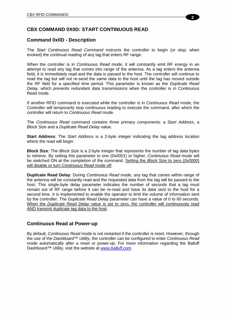
2
To exit out of Continuous Read mode, re-issue the command with zero (0x0000) for the Block Size. Command from Host (Stopping Continuous Read) Parameter Field MSB LSB CBx Header in MSB, Node ID in LSB 0xFF 0x01 Overall Length of Command (in words) 0x00 0x06 0xAA in MSB, Command ID in LSB (0x0D) 0xAA 0x0D 0x00 in MSB, Node ID in LSB 0x00 0x01 0x00 in MSB, Duplicate Read Delay in LSB 0x00 0x02 Start Address 0x00 0x00 Block Size (in bytes) 0x00 0x00
Response from Controller (Continuous Read Stopped) Parameter Field MSB LSB Overall Length of Response (in words) 0x00 0x06 0xAA in MSB, Command Echo in LSB 0xAA 0x0D Instance Counter in MSB. Node ID Echo in LSB <IC> 0x01 Month and Day Timestamp: (March 19th) 0x03 0x13 Hour and Minute Timestamp: (10:12: AM) 0x0A 0x0C Seconds Timestamp in MSB: (:36 seconds). 0x00 in LSB 0x24 0x00
Continuous Read Mode Controller LED Behavior LED Behavior Description READY ON Controller is powered and functioning COM ON Duplicate Read Delay ≥ 1 and a tag has entered the RF field. COM
LED will remain ON while a tag is in the RF field. After the tag has exited the RF field the COM light will remain ON for the duration of the Duplicate Read Delay before turning OFF.
COM BLINKING Duplicate Read Delay = 0 and a tag is in the RF field RF ON Continuous Read mode is enabled
Table 2-2: Continuous Read Mode LED Behavior

CBX PROTOCOL REFERENCE MANUAL
30
2
CBX COMMAND 0X0E: READ TAG ID AND DATA Command 0x0E - Description The Read Tag ID and Data Command instructs the RFID controller to retrieve a tag’s unique identification (Tag ID) number followed by the requested data. The minimum Block Size for read operations is one byte, the maximum Block Size for read operations is 1024 bytes or the entire read/write address space of the tag (minus the number of tag ID bytes), whichever is less. Command 0x0E - CBx Example This example instructs the controller at Node 01 to retrieve the tag ID and two bytes beginning at address 0x0001 from a tag within range of the controller. A Timeout Value of 2 seconds (0x07D0 = 2000 x one-millisecond increments) is set for the completion of the command. In this example the tag ID number retrieved is E0040100002E16AD. Command from Host Parameter Field MSB LSB CBx Header in MSB, Node ID in LSB 0xFF 0x01 Overall Length of Command (in words) 0x00 0x06 0xAA in MSB, Command ID in LSB: (0x0E) 0xAA 0x0E 0x00 in MSB, Node ID in LSB 0x00 0x01 Timeout Value (measured in ms) 0x07 0xD0 Start Address 0x00 0x01 Block Size 0x00 0x02 Response from Controller Parameter Field MSB LSB Overall Length of Response (in words) 0x00 0x06 +
number of additional
words retrieved
0xAA in MSB, Command Echo in LSB 0xAA 0x0E Instance Counter in MSB. Node ID Echo in LSB <IC> 0x01 Month and Day Timestamp: (March 19th) 0x03 0x13 Hour and Minute Timestamp: (10:11: AM) 0x0A 0x0B Seconds Timestamp in MSB: (:36 seconds). Additional Data Length in LSB: (0x0A)
0x24 0x0A
Tag ID (bytes 1 and 2) 0xE0 0x04 Tag ID (bytes 3 and 4) 0x01 0x00 Tag ID (bytes 5 and 6) 0x00 0x2E Tag ID (bytes 7 and 8) 0x16 0xAD Returned Data (bytes 1 and 2) 0x01 0x02

CBX RFID COMMANDS
2
CBX COMMAND 0X0F: START CONTINUOUS READ TAG ID AND DATA Command 0x0F - Description The Start Continuous Read Tag ID and Data Command instructs the controller to repeatedly attempt to retrieve the tag ID and a specified number of tag data bytes from any tag that enters RF range. This command is similar to Command 0x0D; however, Command 0x0F additionally retrieves the tag’s ID number. This command contains four primary parameters: Start Address, Block Size, Start/Stop Flag, and Duplicate Read Delay. Start/Stop Flag: By setting the single-byte Start/Stop Flag parameter to one (0x01), continuous read mode will be switched ON upon execution of the command. Setting the parameter value back to zero (0x00) and re-issuing the command will turn continuous read mode OFF. Duplicate Read Delay: The Duplicate Read Delay is a single-byte value representing the number of seconds that a tag must remain OUT of RF range before it can be re-read and have its data sent to the host for a second time. It is used to limit or prevent the volume of redundant information that is transmitted while the controller is performing continuous reads. The parameter can have a value of 00 to 60 seconds (0x00 – 0x3C). For example, when the Duplicate Read Delay is set to two (0x02), a tag that has already been read must exit the antenna’s RF field for at least two seconds before the controller will recognize it again and re-send its data to the host. When the value is set to zero, the controller will continuously read AND transmit duplicate tag data to the host. Start Address: The Start Address is a 2-byte integer indicating the tag address location where the read operation will begin. Block Size: The Block Size is a 2-byte integer that represents the number of tag data bytes to retrieve, beginning at the specified Start Address location.
CBX PROTOCOL REFERENCE MANUAL
32
2
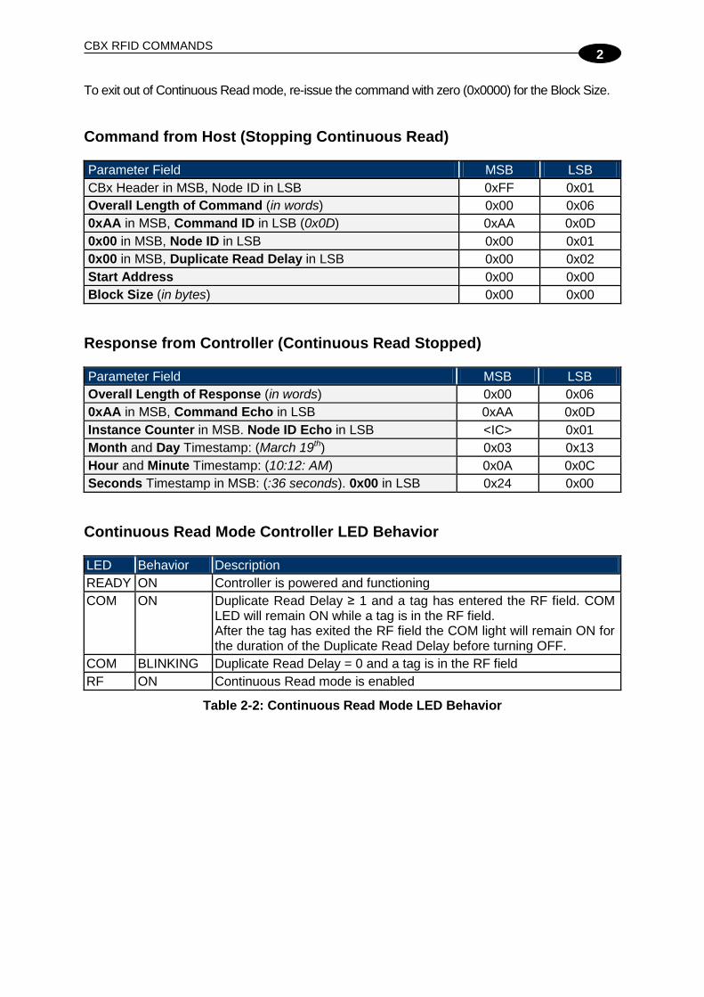
Command 0x0F - CBx Example This example places the controller at Node 01 into Continuous Read Tag ID and Data mode, retrieves the tag ID number and reads four bytes of data starting at address 0x0001 from any tag within range. The Duplicate Read Delay is set for 2 seconds (0x02 = 2 x 1 second increments). Command from Host (Starting Continuous Read) Parameter Field MSB LSB CBx Header in MSB, Node ID in LSB 0xFF 0x01 Overall Length of Command (in words) 0x00 0x06 0xAA in MSB, Command ID in LSB: (0x0F) 0xAA 0x0F 0x00 in MSB, Node ID in LSB 0x00 0x01 Start/Stop Flag in MSB (0x01 = START, 0x00 = STOP) Duplicate Read Delay in LSB (measured in seconds)
0x01 0x02
Start Address 0x00 0x01 Block Size 0x00 0x04
Response from Controller (Continuous Read Evoked) Parameter Field MSB LSB Overall Length of Response (in words) 0x00 0x0C 0xAA in MSB, Command Echo in LSB 0xAA 0x0F Instance Counter in MSB, Node ID Echo in LSB <IC> 0x01 Month and Day Timestamp: (March 19th) 0x03 0x13 Hour and Minute Timestamp: (10:11: AM) 0x0A 0x0B Seconds Timestamp in MSB: (:36 seconds) Additional Data Length in LSB: (12 bytes)
0x24 0x0C
Tag ID (bytes 1 and 2) 0xE0 0x04 Tag ID (bytes 3 and 4) 0x01 0x00 Tag ID (bytes 5 and 6) 0x00 0x10 Tag ID (bytes 7 and 8) 0x09 0x61 Returned Data (bytes 1 and 2) 0x01 0x02 Returned Data (bytes 3 and 4) 0x03 0x04

CBX RFID COMMANDS
2
To exit out of Continuous Read Tag ID and Data mode, re-issue the command with zero (0x00) in the Start/Stop Flag field. Command from Host (Stopping Continuous Read) Parameter Field MSB LSB CBx Header in MSB, Node ID in LSB 0xFF 0x01 Overall Length of Command (in words) 0x00 0x06 0xAA in MSB, Command ID in LSB (0x0F) 0xAA 0x0F 0x00 in MSB, Node ID in LSB 0x00 0x01 Start/Stop Flag in MSB (0x01 = START, 0x00 = STOP) Duplicate Read Delay in LSB
0x00 0x02
Start Address 0x00 0x01 Block Size (in bytes) 0x00 0x00
Response from Controller (Continuous Read Stopped)
Parameter Field MSB LSB Overall Length of Response (in words) 0x00 0x06 0xAA in MSB, Command Echo in LSB 0xAA 0x0F Instance Counter in MSB, Node ID Echo in LSB <IC> 0x01 Month and Day Timestamp: (March 19th) 0x03 0x13 Hour and Minute Timestamp: (10:11: AM) 0x0A 0x0B Seconds Timestamp in MSB: (:36 seconds). 0x00 in LSB 0x24 0x00

CBX PROTOCOL REFERENCE MANUAL
34
2
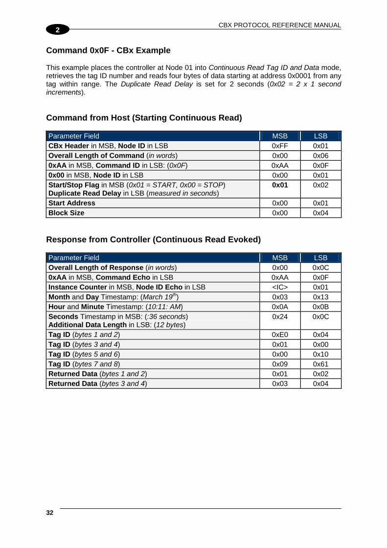
CBX COMMAND 0X10: GET GATEWAY/HUB SOFTWARE VERSION Command 0x10 - Description The Get Gateway/Hub Software Version Command is used to retrieve the version number of the firmware code installed on the Gateway/Hub. Command 0x10 - CBx Example This example retrieves the software version from an Industrial Hub interface module. The software version retrieved in this example is the 20-byte string: 48 55 42 2D 30 34 2D 49 4E 44 2D 30 31 20 76 31 2E 31 2E 47, which correspond to the ASCII characters: HUB-04-IND-01 v1.1.G. Command from Host Parameter Field MSB LSB CBx Header in MSB, Node ID in LSB 0xFF 0x20 Overall Length of Command (in words) 0x00 0x06 0xAA in MSB, Command ID in LSB: (0x10) 0xAA 0x10 0x00 in MSB, Node ID in LSB 0x00 0x20 Not Used (0x00, 0x00) 0x00 0x00 Not Used (0x00, 0x00) 0x00 0x00 Not Used (0x00, 0x00) 0x00 0x00
Response from Gateway/Hub Parameter Field MSB LSB CBx Header in MSB, Node ID in LSB 0xFF 0x20 Overall Length of Response (in words) 0x00 0x10 0xAA in MSB, Command Echo in LSB 0xAA 0x10 Instance Counter in MSB, Node ID Echo in LSB <IC> 0x20 Month and Day Timestamp: (March 19th) 0x03 0x13 Hour and Minute Timestamp: (10:11: AM) 0x0A 0x0B Seconds Timestamp in MSB: (:36 seconds). Additional Data Length in LSB: (20 bytes)
0x24 0x14
Software Version Character: bytes 1 and 2 0x48 <H> 0x55 <U> Software Version Character: bytes 3 and 4 0x42 <B> 0x2D <-> Software Version Character: bytes 5 and 6 0x30 <0> 0x34 <4> Software Version Character: bytes 7 and 8 0x2D <-> 0x49 <I> Software Version Character: bytes 9 and 10 0x4E <N> 0x44 <D> Software Version Character: bytes 11 and 12 0x2D <-> 0x30 <0> Software Version Character: bytes 13 and 14 0x31 <1> 0x20 <space> Software Version Character: bytes 15 and 16 0x76 <v> 0x31 <1> Software Version Character: bytes 17 and 18 0x2E <.> 0x31 <1> Software Version Character: bytes 19 and 20 0x2E <.> 0x47 <G>

CBX RFID COMMANDS
2
CBX COMMAND 0X11: GET GATEWAY/HUB NAME Command 0x11 - Description The Get Gateway/Hub Name Command is used to retrieve the Gateway/Hub’s user-defined ASCII name. Command 0x11 - CBx Example This example retrieves the user-defined name from an Industrial Hub interface module. The name retrieved in this example is the 11-byte string: 48 55 42 20 49 4E 44 20 48 55 42, which correspond to the ASCII characters: HUB IND HUB. Command from Host Parameter Field MSB LSB CBx Header in MSB, Node ID in LSB 0xFF 0x20 Overall Length of Command (in words) 0x00 0x06 0xAA in MSB, Command ID in LSB: (0x11) 0xAA 0x11 0x00 in MSB, Node ID in LSB 0x00 0x20 Not Used (0x00, 0x00) 0x00 0x00 Not Used (0x00, 0x00) 0x00 0x00 Not Used (0x00, 0x00) 0x00 0x00
Response from Gateway/Hub Parameter Field MSB LSB CBx Header in MSB, Node ID in LSB 0xFF 0x20 Overall Length of Response (in words) 0x00 0x0C 0xAA in MSB, Command Echo in LSB 0xAA 0x11 Instance Counter in MSB, Node ID Echo in LSB <IC> 0x20 Month and Day Timestamp: (March 19th) 0x03 0x13 Hour and Minute Timestamp: (10:11: AM) 0x0A 0x0B Seconds Timestamp in MSB (:36 seconds). Additional Data Length in LSB: (11 bytes)
0x24 0x0B
Hub Name Data Bytes: bytes 1 and 2 0x48 <H> 0x55 <U> Hub Name Data Bytes: bytes 3 and 4 0x42 <B> 0x20 <space> Hub Name Data Bytes: bytes 5 and 6 0x49 <I> 0x4E <N> Hub Name Data Bytes: bytes 7 and 8 0x44 <D> 0x20 <space> Hub Name Data Bytes: bytes 9 and 10 0x48 <H> 0x55 <U> Hub Name Data Byte: byte 11 0x00 in LSB
0x42 <B> 0x00

CBX PROTOCOL REFERENCE MANUAL
36
2
CBX COMMAND 0X12: GET DIPSWITCH SETTINGS Command 0x12 - Description The Get Dipswitch Settings Command is used to retrieve the status of the Gateway/Hub’s three main configuration dipswitches. The resulting response for this command will include a 1-byte value representing the current settings of dipswitches 1-3. Of this one byte, the lowest 3 bits represent the ON/OFF status of dipswitches 1 - 3 (dipswitches 4 - 8 are not applicable and should not be altered).
Command 0x12 - CBx Example This example retrieves the dipswitch settings from an Industrial Hub interface module. Command from Host Parameter Field MSB LSB CBx Header in MSB, Node ID in LSB 0xFF 0x20 Overall Length of Command (in words) 0x00 0x06 0xAA in MSB, Command ID in LSB: (0x12) 0xAA 0x12 0x00 in MSB, Node ID in LSB 0x00 0x20 Not Used (0x00, 0x00) 0x00 0x00 Not Used (0x00, 0x00) 0x00 0x00 Not Used (0x00, 0x00) 0x00 0x00
Response from Gateway/Hub Parameter Field MSB LSB CBx Header in MSB, Node ID in LSB 0xFF 0x20 Overall Length of Response (in words) 0x00 0x07 0xAA in MSB, Command Echo in LSB 0xAA 0x12 Instance Counter in MSB, Node ID Echo in LSB <IC> 0x20 Month and Day Timestamp: (March 19th) 0x03 0x13 Hour and Minute Timestamp: (10:11: AM) 0x0A 0x0B Seconds Timestamp in MSB: (:36 seconds). Additional Data Length in LSB: (one byte)
0x24 0x01
Dipswitch Settings Value in MSB. 0x00 in LSB 0x03 0x00

CBX RFID COMMANDS
2
The dipswitch settings value “0x03” was retrieved in the above example, meaning that dipswitches 1 and 2 are ON. Dipswitch Settings Value Definition Table
Dipswitch Settings Value Description 0x00 Dipswitches 1-3 are OFF 0x01 Dipswitch 1 is ON 0x02 Dipswitch 2 is ON 0x03 Dipswitch 1 and 2 are ON 0x04 Dipswitch 3 is ON 0x05 Dipswitch 1 and 3 are ON 0x06 Dipswitch 2 and 3 are ON 0x07 All 3 Dipswitches are ON
Table 2-3: Dipswitch Settings Value Definitions

CBX PROTOCOL REFERENCE MANUAL
38
2
CBX COMMAND 0X13: GET NODE STATUS LIST Command 0x13 - Description The Get Node Status List Command is used to retrieve the operational status of the Gateway/Hub’s Subnet Nodes. The response will include a list containing a number of individual Node Status Bytes (16 for the Gateway, 4 for the Hub), where each byte indicates the status for the corresponding Node ID. Command 0x13 – CBx Example This example retrieves the Node Status List from a Gateway interface module. Command from Host Parameter Field MSB LSB CBx Header in MSB, Node ID in LSB 0xFF 0x20 Overall Length of Command (in words) 0x00 0x06 0xAA in MSB. Command ID in LSB: (0x13) 0xAA 0x13 0x00 in MSB, Node ID in LSB 0x00 0x20 Not Used (0x00, 0x00) 0x00 0x00 Not Used (0x00, 0x00) 0x00 0x00 Not Used (0x00, 0x00) 0x00 0x00
Response from Gateway/Hub Parameter Field MSB LSB CBx Header in MSB, Node ID in LSB 0xFF 0x20 Overall Length of Response (in words) 0x00 0x0E 0xAA in MSB, Command Echo in LSB 0xAA 0x13 Instance Counter in MSB. Node ID Echo in LSB <IC> 0x20 Month and Day Timestamp: (March 19th) 0x03 0x13 Hour and Minute Timestamp: (10:11: AM) 0x0A 0x0B Seconds Timestamp in MSB: (36 seconds). Additional Data Length in LSB: (4 bytes)
0x24 0x04
Status for Node ID 1 and 2 0x04 0x04 Status for Node ID 3 and 4 0x04 0x04 Status for Node ID 5 and 6 0x04 0x04 Status for Node ID 7 and 8 0x04 0x04 Status for Node ID 9 and 10 0x04 0x04 Status for Node ID 11 and 12 0x04 0x04 Status for Node ID 13 and 14 0x04 0x04 Status for Node ID 15 and 16 0x04 0x04
In the above example response, all sixteen nodes report “0x04 – Controller Healthy.”

CBX RFID COMMANDS
2
Node Status Byte Definition Table
Node Status Byte
Node Status Description
0x00 CONTROLLER INACTIVE
No controller has responded to a poll at this Node ID for at least 40 seconds. If a controller does eventually respond at this Node ID, its status will be changed to “0x04 - CONTROLLER HEALTHY”
0x01 CONTROLLER STOPPED
RESPONDING
The controller at this Node ID has not responded to a poll in over 10 seconds. If the controller does not respond to a poll within another 30 seconds, its status will be changed to “0x00 - CONTROLLER INACTIVE” If the controller does respond to a poll, its status will be changed back to “0x04 - CONTROLLER HEALTHY”
0x02 CONTROLLER HAS PROBLEM
The controller at this Node ID has missed at least 3 consecutive polls. If the controller does not respond to a poll within another 10 seconds, its status will be changed to “0x01 - CONTROLLER STOPPED RESPONDING” If the controller does respond to a poll, its status will be changed back to “0x04 - CONTROLLER HEALTHY”
0x03 CONTROLLER EXPECTED SOON
This Node Status indicates that a controller is temporarily disconnected or that it is being moved to another Node ID to another. Because a controller is “expected” to appear soon, the Gateway/Hub will poll this Node more frequently than other ‘inactive’ nodes.
0x04 CONTROLLER HEALTHY
The controller is healthy and responding to polls. However, if the controller misses 3 consecutive polls, its status will be changed to “0x02 - CONTROLLER HAS PROBLEM.”
0x05 CONTROLLER DOWNLOADING
This status is only applied to a controller that is currently downloading and installing new firmware to its flash memory. To optimize polling and allow for the fastest possible firmware installation, the Hub will temporarily halt the polling of this node until the controller has finished its installation.
Table 2-4: Node Status Byte Definitions
CBX PROTOCOL REFERENCE MANUAL
40
2
CBX COMMAND 0X14: GET NOTIFICATION MASK Command 0x14 - Description The Get Notification Mask Command is used to retrieve the user-defined 16-bit “Notification Mask” that determines for which events the Gateway/Hub notifies the host PC. The lowest 13 bits of the Notification Mask identify whether a Notification Message is enabled (1 = ON) or disabled (0 = OFF) when a particular Notification Event occurs.
NOTE
For more information regarding the Notification Mask, see Command 0x24: Set Notification Mask.
Command 0x14 - CBx Example This example retrieves the Notification Mask from an Industrial Hub interface module. Command from Host Parameter Field MSB LSB CBx Header in MSB, Node ID in LSB 0xFF 0x20 Overall Length of Command (in words) 0x00 0x06 0xAA in MSB, Command ID in LSB: (0x14) 0xAA 0x14 0x00 in MSB, Node ID in LSB 0x00 0x20 Not Used (0x00, 0x00) 0x00 0x00 Not Used (0x00, 0x00) 0x00 0x00 Not Used (0x00, 0x00) 0x00 0x00
Response from Gateway/Hub Parameter Field MSB LSB CBx Header in MSB, Node ID in LSB 0xFF 0x20 Overall Length of Response (in words) 0x00 0x07 0xAA in MSB, Command Echo in LSB 0xAA 0x14 Instance Counter in MSB, Node ID Echo in LSB <IC> 0x20 Month and Day Timestamp: (March 19th) 0x03 0x13 Hour and Minute Timestamp: (10:11: AM) 0x0A 0x0B Seconds Timestamp in MSB (:36 seconds). Additional Data Length in LSB: (2 bytes)
0x24 0x02
16-bit Notification Mask 0x1F 0xFF In the above example response, the Notification Mask is 0x1FFF, meaning that all 13 Notification Messages are enabled.

CBX RFID COMMANDS
2
Notification Message Table The following table lists the 13 Notification Messages, their bit mask values and contains a description of the Notification Event that can be set to trigger the notification.
Bit Notification Message Notification Event Description 1 CONTROLLER IS HEALTHY Sent whenever the status of a controller changes to
‘Healthy’ 2 CONTROLLER HAS PROBLEM Sent whenever a controller is marked ‘Has Problem’ 3 CONTROLLER STOPPED
RESPONDING Sent whenever a controller is marked ‘Stopped Responding’
4 CONTROLLER DEACTIVATED Sent whenever a controller is deactivated (is marked ‘Inactive’)
5 CONTROLLER MISSED POLL Sent whenever a controller misses a poll 6 CONTROLLER ADDRESS
CONFLICT Sent whenever the Gateway/Hub detects a Node ID conflict
7 CONTROLLER CONFIGURATION FAILURE
Sent whenever the Gateway/Hub fails to configure a controller
8 TAG PRESENT AT NODE * Sent whenever a tag is first recognized in the RF field of the specified node
9 TAG NOT PRESENT AT NODE * Sent whenever a tag is no longer recognized within or has exited the RF field of the specified node
10 INPUT SET (Hub only) Sent when one of the Hub's four Inputs has been set 11 INPUT CLEARED (Hub only) Sent when one of the Hub's four Inputs has been
cleared 12 OUTPUT SET (Hub only) Sent when one of the Hub's four Outputs has been set 13 OUTPUT CLEARED (Hub only) Sent when one of the Hub's four Outputs has been
cleared
Table 2-5: Notification Message Table * - Tag Presence must be enabled on the RFID controller.
NOTE
The Gateway only supports Notification Messages 1 – 9. Notification Messages 10 – 13 pertain to the status of the RFID Controller or Hub’s Digital Inputs and Outputs.

CBX PROTOCOL REFERENCE MANUAL
42
2
CBX COMMAND 0X15: GET LAST GATEWAY/HUB ERROR Command 0x15 - Description The Get Last Gateway/Hub Error Command is used to retrieve information from the Gateway/Hub regarding the last or most recent error that was experienced by the Gateway/Hub or one of its RFID controllers on the Subnet16 network. The generated response will include 1-byte values for the error code and the Node ID of the device that experienced the error, and may contain an additional text string of further information (“Error Details”). When the Gateway/Hub is power cycled, any stored error information will be deleted. Command 0x15 - Description This example retrieves from an Industrial Hub interface module data concerning the most recent error experienced. Command from Host Parameter Field MSB LSB CBx Header in MSB, Node ID in LSB 0xFF 0x20 Overall Length of Command (in words) 0x00 0x06 0xAA in MSB, Command ID in LSB: (0x15) 0xAA 0x15 0x00 in MSB, Node ID in LSB 0x00 0x20 Not Used (0x00, 0x00) 0x00 0x00 Not Used (0x00, 0x00) 0x00 0x00 Not Used (0x00, 0x00) 0x00 0x00

CBX RFID COMMANDS
2
Response from Gateway/Hub
Parameter Field MSB LSB CBx Header in MSB, Node ID in LSB 0xFF 0x20 Overall Length of Response (in words) 0x00 0x12 0xAA in MSB, Command Echo in LSB 0xAA 0x15 Instance Counter in MSB, Node ID Echo in LSB <IC> 0x20 Error Code in MSB. Error Node (device that experienced the error) in LSB
0x8A 0x04
Error Hour and Minute Timestamp: (2:07:PM) 0x0E 0x07 Error Seconds Timestamp in MSB: (:52 seconds). Additional Data Length in LSB: (23 bytes)
0x34 0x17
Error Details Returned Data: bytes 1 and 2 0x53 <S> 0x75 <u> Error Details Returned Data: bytes 3 and 4 0x62 <b> 0x6E <n> Error Details Returned Data: bytes 5 and 6 0x65 <e> 0x74 <t> Error Details Returned Data: bytes 7 and 8 0x20 <space> 0x52 <R> Error Details Returned Data: bytes 9 and 10 0x65 <e> 0x73 <s> Error Details Returned Data: bytes 11 and 12 0x70 <p> 0x6F <o> Error Details Returned Data: bytes 13 and 14 0x6E <n> 0x73 <s> Error Details Returned Data: bytes 15 and 16 0x65 <e> 0x20 <space> Error Details Returned Data: bytes 17 and 18 0x54 <T> 0x69 <i> Error Details Returned Data: bytes 19 and 20 0x6D <m> 0x65 <e> Error Details Returned Data: bytes 21 and 22 0x6F <o> 0x75 <u> Error Details Returned Data: byte 23. 0x00 in LSB 0x74 <t> 0x00
In the above example response, error code 0x8A was reported on Node ID 04 at 2:07:52 P.M. Error Details = "Subnet Response Timeout."

CBX PROTOCOL REFERENCE MANUAL
44
2
CBX COMMAND 0X16: GET GATEWAY/HUB TIME Command 0x16 - Description The Get Gateway/Hub Time Command is used to retrieve the current date and time as set internally on the Gateway/Hub. Date and time are returned in the following format: Year MSB:LSB (2-byte Integer) Month (byte), Day of Month (byte) Hour (byte), Minute (byte) Seconds (byte) Command 0x16 – CBx Example This example retrieves the date and time from an Industrial Hub interface module. Command from Host Parameter Field MSB LSB CBx Header in MSB, Node ID in LSB 0xFF 0x20 Overall Length of Command (in words) 0x00 0x06 0xAA in MSB, Command ID in LSB: (0x16) 0xAA 0x16 0x00 in MSB, Node ID in LSB 0x00 0x20 Not Used (0x00, 0x00) 0x00 0x00 Not Used (0x00, 0x00) 0x00 0x00 Not Used (0x00, 0x00) 0x00 0x00
Response from Gateway/Hub Parameter Field MSB LSB CBx Header in MSB, Node ID in LSB 0xFF 0x20 Overall Length of Response (in words) 0x00 0x0A 0xAA in MSB, Command Echo in LSB 0xAA 0x16 Instance Counter in MSB, Node ID Echo in LSB <IC> 0x20 Month and Day Timestamp: (May 23) 0x05 0x17 Hour and Minute Timestamp: (2:08 PM) 0x0E 0x08 Seconds Timestamp in MSB: (:03 seconds). Additional Data Length in LSB: (7 bytes)
0x03 0x07
Year: (2007) 0x07 0xD7 Month and Day: (May 23) 0x05 0x17 Hours and Minutes: (2:08 P.M) 0x0E 0x08 Seconds in MSB: (:03 seconds). 0x00 in LSB 0x03 0x00
In the above example response, the date and time retrieved is: 2007, May 23, 14:08:03

CBX RFID COMMANDS
2
CBX COMMAND 0X1A: GET DIGITAL INPUTS Command 0x1A - Description The Get Digital Inputs Command is used to retrieve the 8-bit Digital Input State value, which identifies the status of the device’s digital input(s). Currently HF and UHF I/O model controllers as well as the Hubs are equipped with one or more Digital Inputs. See the Digital Input State Table on the following page for definitions. Command 0x1A – CBx Example This example retrieves the status of the four Hub Inputs. Command from Host Parameter Field MSB LSB CBx Header in MSB, Node ID in LSB 0xFF 0x20 Overall Length of Command (in words) 0x00 0x06 0xAA in MSB, Command ID in LSB: (0x1A) 0xAA 0x1A 0x00 in MSB, Node ID in LSB 0x00 0x20 Not Used (0x00, 0x00) 0x00 0x00 Not Used (0x00, 0x00) 0x00 0x00 Not Used (0x00, 0x00) 0x00 0x00
Response from Device Parameter Field MSB LSB CBx Header in MSB, Node ID in LSB 0xFF 0x20 Overall Length of Response (in words) 0x00 0x07 0xAA in MSB, Command Echo in LSB 0xAA 0x1A Instance Counter in MSB, Node ID Echo in LSB <IC> 0x20 Month and Day Timestamp: (May 23) 0x05 0x17 Hour and Minute Timestamp: (2:08 PM) 0x0E 0x08 Seconds Timestamp in MSB (:03 seconds). Additional Data Length in LSB: (2 bytes)
0x03 0x02
0x00 in MSB. Digital Input State in LSB: (lowest four bits indicate the state of the Hub's Digital Inputs: 0x0F = all four Hub Inputs are set).
0x00 0x0F

CBX PROTOCOL REFERENCE MANUAL
46
2
Digital Input State Table LSB BINARY VALUE RESULT always zero Inputs
D C B A
0x0F 0 0 0 0 1 1 1 1 all Digital Inputs (hub) = Set … … … … 0x04 0 0 0 0 0 1 0 0 only Input C (hub) = Set 0x03 0 0 0 0 0 0 1 1 only Input A and B (hub) = Set 0x02 0 0 0 0 0 0 1 0 only Input B (hub) = Set 0x01 0 0 0 0 0 0 0 1 Digital Input 1 (controller) or Input A (hub) = Set
Input B, C, D (hub) = Clear 0x00 0 0 0 0 0 0 0 0 Digital Input 1 (controller) = Clear
all Digital Inputs (hub) = Clear
Table 2-6: Digital Input State
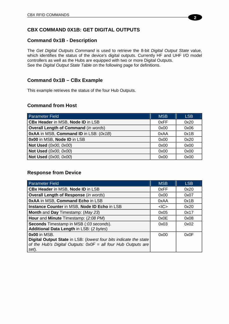
CBX RFID COMMANDS
2
CBX COMMAND 0X1B: GET DIGITAL OUTPUTS Command 0x1B - Description The Get Digital Outputs Command is used to retrieve the 8-bit Digital Output State value, which identifies the status of the device's digital outputs. Currently HF and UHF I/O model controllers as well as the Hubs are equipped with two or more Digital Outputs. See the Digital Output State Table on the following page for definitions. Command 0x1B – CBx Example This example retrieves the status of the four Hub Outputs. Command from Host Parameter Field MSB LSB CBx Header in MSB, Node ID in LSB 0xFF 0x20 Overall Length of Command (in words) 0x00 0x06 0xAA in MSB, Command ID in LSB: (0x1B) 0xAA 0x1B 0x00 in MSB, Node ID in LSB 0x00 0x20 Not Used (0x00, 0x00) 0x00 0x00 Not Used (0x00, 0x00) 0x00 0x00 Not Used (0x00, 0x00) 0x00 0x00
Response from Device Parameter Field MSB LSB CBx Header in MSB, Node ID in LSB 0xFF 0x20 Overall Length of Response (in words) 0x00 0x07 0xAA in MSB, Command Echo in LSB 0xAA 0x1B Instance Counter in MSB, Node ID Echo in LSB <IC> 0x20 Month and Day Timestamp: (May 23) 0x05 0x17 Hour and Minute Timestamp: (2:08 PM) 0x0E 0x08 Seconds Timestamp in MSB (:03 seconds). Additional Data Length in LSB: (2 bytes)
0x03 0x02
0x00 in MSB. Digital Output State in LSB: (lowest four bits indicate the state of the Hub's Digital Outputs: 0x0F = all four Hub Outputs are set).
0x00 0x0F
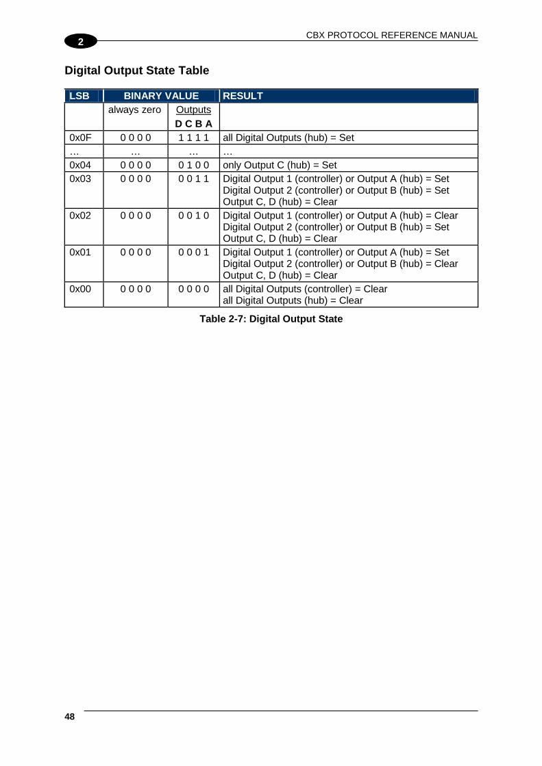
CBX PROTOCOL REFERENCE MANUAL
48
2
Digital Output State Table LSB BINARY VALUE RESULT always zero Outputs
D C B A
0x0F 0 0 0 0 1 1 1 1 all Digital Outputs (hub) = Set … … … … 0x04 0 0 0 0 0 1 0 0 only Output C (hub) = Set 0x03 0 0 0 0 0 0 1 1 Digital Output 1 (controller) or Output A (hub) = Set
Digital Output 2 (controller) or Output B (hub) = Set Output C, D (hub) = Clear
0x02 0 0 0 0 0 0 1 0 Digital Output 1 (controller) or Output A (hub) = Clear Digital Output 2 (controller) or Output B (hub) = Set Output C, D (hub) = Clear
0x01 0 0 0 0 0 0 0 1 Digital Output 1 (controller) or Output A (hub) = Set Digital Output 2 (controller) or Output B (hub) = Clear Output C, D (hub) = Clear
0x00 0 0 0 0 0 0 0 0 all Digital Outputs (controller) = Clear all Digital Outputs (hub) = Clear
Table 2-7: Digital Output State

CBX RFID COMMANDS
2
CBX COMMAND 0X1C: GET SUBNET BAUD RATE Command 0x1C - Description The Get Subnet Baud Rate Command is used to retrieve the baud rate of the Subnet network. The response will contain a one-byte Baud Rate Index Value that indicates the current baud rate of the Subnet. See the Baud Rate Index Table of the following page for definitions. Command 0x1C – CBx Example This example retrieves the baud rate of the Subnet network. Command from Host Parameter Field MSB LSB CBx Header in MSB, Node ID in LSB 0xFF 0x20 Overall Length of Command (in words) 0x00 0x06 0xAA in MSB, Command ID in LSB: (0x1C) 0xAA 0x1C 0x00 in MSB, Node ID in LSB 0x00 0x20 Not Used (0x00, 0x00) 0x00 0x00 Not Used (0x00, 0x00) 0x00 0x00 Not Used (0x00, 0x00) 0x00 0x00
Response from Gateway/Hub Parameter Field MSB LSB CBx Header in MSB, Node ID in LSB 0xFF 0x20 Overall Length of Response (in words) 0x00 0x07 0xAA in MSB, Command Echo in LSB 0xAA 0x1C Instance Counter in MSB, Node ID Echo in LSB <IC> 0x20 Month and Day Timestamp: (May 23) 0x05 0x17 Hour and Minute Timestamp: (2:08 PM) 0x0E 0x08 Seconds Timestamp in MSB (:03 seconds). Additional Data Length in LSB: (one byte)
0x03 0x01
Baud Rate Index Value in MSB: (0x00 = 9600 baud). 0x00 in LSB 0x00 0x00 Baud Rate Index Table
Baud Rate Index Value 9600 Baud 0x00 19200 Baud 0x01 38400 Baud 0x02 57600 Baud 0x03 115200 Baud 0x04
Table 2-8: Baud Rate Index

CBX PROTOCOL REFERENCE MANUAL
50
2
CBX COMMAND 0X21: SET GATEWAY/HUB NAME Command 0x21 - Description The Set Gateway/Hub Name Command is used to write to flash memory, a user-defined “friendly” name for the Gateway/Hub. The Gateway/Hub name can contain up to 64 bytes of data. Command 0x21 - CBx Example This example sets the user-defined Hub name to DLA IND HUB1. Command from Host Parameter Field MSB LSB CBx Header in MSB, Node ID in LSB 0xFF 0x20 Overall Length of Command (in words) 0x00 0x0C (0x06 +
number words in Gateway/Hub
name) 0xAA in MSB, Command ID in LSB: (0x21) 0xAA 0x21 0x00 in MSB, Node ID in LSB 0x00 0x20 Not Used (0x00, 0x00) 0x00 0x00 Not Used (0x00, 0x00) 0x00 0x00 0x00 in MSB Hub Name Length (in bytes) in LSB: (12 bytes)
0x00 0x0C
Hub Name Data (ASCII characters 1 & 2) 0x44 <D> 0x4C <L> Hub Name Data (ASCII characters 3 & 4) 0x41 <A> 0x20 <space> Hub Name Data (ASCII characters 5 & 6) 0x49 <I> 0x4E <N> Hub Name Data (ASCII characters 7 & 8) 0x44 <D> 0x20 <space> Hub Name Data (ASCII characters 9 & 10) 0x48 <H> 0x55 <U> Hub Name Data (ASCII characters 11 & 12) 0x42 <B> 0x31 <1>
Response from Gateway/Hub Parameter Field MSB LSB CBx Header in MSB, Node ID in LSB 0xFF 0x20 Overall Length of Response (in words) 0x00 0x06 0xAA in MSB, Command Echo in LSB 0xAA 0x21 Instance Counter in MSB, Node ID Echo in LSB <IC> 0x20 Month and Day Timestamp: (March 19th) 0x03 0x13 Hour and Minute Timestamp: (10:11: AM) 0x0A 0x0B Seconds Timestamp in MSB: (:36 seconds). 0x00 in LSB 0x24 0x00

CBX RFID COMMANDS
2
CBX COMMAND 0X24: SET NOTIFICATION MASK Command 0x24 - Description The Set Notification Mask Command is used to modify and save changes to the Gateway/Hub’s 16-bit Notification Mask. Stored in flash memory, the user-defined Notification Mask determines for which events the Gateway/Hub sends a Notification Message to the host. Notification Messages are small host-bound informational packets of data that are issued by a Gateway/Hub when a specified Notification Event occurs within the Gateway/Hub or on the Subnet16™ network. The Gateway/Hub stores 9 different Notification Messages internally. The Hub stores an additional 4 Notification Messages relative to its Inputs/Outputs. See the Notification Message Table below. Notification Message Table The following table lists the Notification Messages, their bit mask values and contains a description of the Notification Event that can be set to trigger the notification.
Bit Notification Message Notification Event Description 1 CONTROLLER IS HEALTHY Sent whenever the status of a controller changes to
‘Healthy’ 2 CONTROLLER HAS PROBLEM Sent whenever a controller is marked ‘Has Problem’ 3 CONTROLLER STOPPED
RESPONDING Sent whenever a controller is marked ‘Stopped Responding’
4 CONTROLLER DEACTIVATED Sent whenever a controller is deactivated (is marked ‘Inactive’)
5 CONTROLLER MISSED POLL Sent whenever a controller misses a poll 6 CONTROLLER ADDRESS
CONFLICT Sent whenever the Gateway/Hub detects a Node ID conflict
7 CONTROLLER CONFIGURATION FAILURE
Sent whenever the Gateway/Hub fails to configure a controller
8 TAG PRESENT AT NODE * Sent whenever a tag is first recognized in the RF field of the specified node
9 TAG NOT PRESENT AT NODE * Sent whenever a tag is no longer recognized within or has exited the RF field of the specified node
10 INPUT SET (Hub only) Sent when one of the Hub's four Inputs has been set 11 INPUT CLEARED (Hub only) Sent when one of the Hub's four Inputs has been
cleared 12 OUTPUT SET (Hub only) Sent when one of the Hub's four Outputs has been set 13 OUTPUT CLEARED (Hub only) Sent when one of the Hub's four Outputs has been
cleared
Table 2-9: Notification Message Table * - Tag Presence must be enabled on the RFID controller.

CBX PROTOCOL REFERENCE MANUAL
52
2
NOTE
The Gateway only supports Notification Messages 1 – 9. Notification Messages 10 – 13 pertain to the status of the Hub’s Digital Inputs and Outputs.
Notification Messages are enabled or disabled by setting the corresponding bit within the 16-bit Notification Mask. Bits 01 through 13 each represent one of the Notification Messages. A bit is either set to “1” (ON = enabled) or “0” (OFF = disabled). If a bit is turned ON, the corresponding Notification Message will be generated when the specified event occurs. See par. 1.4 for details on Notification Event Messages. By default, all Notification Messages are enabled (i.e. the 16-bit Notification Mask is 0x1FFF). 16-bit Notification Mask - Binary Representation - when enabling all 13 Notification Messages:
(0 0 0 1 1 1 1 1) (1 1 1 1 1 1 1 1) = 0x1FFF [Bit 16 - - Bit 09] [Bit 08 - - Bit 01]
To disable all 13 Notification Messages, set the Notification Mask to 0x0000. Command 0x24 - CBx Example This example sets the user-defined Notification Mask to 0x1FFF, which enables all 13 Notification Messages. Command from Host Parameter Field MSB LSB CBx Header in MSB, Node ID in LSB 0xFF 0x20 Overall Length of Command (in words) 0x00 0x07 0xAA in MSB, Command ID in LSB: (0x24) 0xAA 0x24 0x00 in MSB, Node ID in LSB 0x00 0x20 Not Used (0x00, 0x00) 0x00 0x00 Not Used (0x00, 0x00) 0x00 0x00 0x00 in MSB. Notification Mask Length in LSB: (2 bytes) 0x00 0x02 16-bit Notification Mask 0x1F 0xFF
Response from Gateway/Hub Parameter Field MSB LSB CBx Header in MSB, Node ID in LSB 0xFF 0x20 Overall Length of Response (in words) 0x00 0x06 0xAA in MSB, Command Echo in LSB 0xAA 0x24 Instance Counter in MSB, Node ID Echo in LSB <IC> 0x20 Month and Day Timestamp: (March 19th) 0x03 0x13 Hour and Minute Timestamp: (10:11: AM) 0x0A 0x0B Seconds Timestamp in MSB: (:36 seconds). 0x00 in LSB: 0x24 0x00

CBX RFID COMMANDS
2
CBX COMMAND 0X26: SET GATEWAY/HUB TIME Command 0x26 - Description The Set Gateway/Hub Time Command is used to set the Gateway/Hub’s internal clock and calendar. Date and time are specified in the following format: Year MSB:LSB (2-byte Integer) Month (byte), Day of Month (byte) Hour (byte), Minute (byte) Seconds (byte) Command 0x26 - CBx Example This example sets the date and time of the Hub to that of the host PC, which, in this example, is 2007, May 23, 3:19:44 PM. Command from Host Parameter Field MSB LSB CBx Header in MSB, Node ID in LSB 0xFF 0x20 Overall Length of Command (in words) 0x00 0x0A 0xAA in MSB, Command ID in LSB: (0x26) 0xAA 0x26 0x00 in MSB, Node ID in LSB 0x00 0x20 Not Used (0x00, 0x00) 0x00 0x00 Not Used (0x00, 0x00) 0x00 0x00 0x00 in MSB Time/Date Data Length in LSB: (7 bytes)
0x00 0x07
Year: (2007) 0x07 0xD7 Month and Day: (May 23) 0x05 0x17 Hour and Minute: (3:19 PM) 0x0F 0x13 Seconds in MSB: (:44 seconds). 0x00 in LSB 0x2C 0x00
Response from Gateway/Hub Parameter Field MSB LSB CBx Header in MSB, Node ID in LSB 0xFF 0x20 Overall Length of Response (in words) 0x00 0x06 0xAA in MSB, Command Echo in LSB 0xAA 0x26 Instance Counter in MSB, Node ID Echo in LSB <IC> 0x20 Month and Day Timestamp: (May 23h) 0x05 0x17 Hour and Minute Timestamp: (03:19: P.M.) 0x0F 0x13 Seconds Timestamp in MSB: (:44 seconds). 0x00 in LSB 0x2C 0x07

CBX PROTOCOL REFERENCE MANUAL
54
2
CBX COMMAND 0X2A: SET/CLEAR DIGITAL OUTPUTS Command 0x2A - Description The Set/Clear Digital Outputs Command is used to set or clear any or all of the device’s digital outputs. The 8-bit Digital Output Mask is used to select which of the Digital Outputs you wish to affect (i.e., which Digital Outputs will be set or cleared). The 8-bit Data State is used to indicate whether the affected Digital Outputs will either be set (1 = SET) or cleared (0 = CLEAR). Currently HF and UHF I/O model controllers as well as the Hubs are equipped with two or more Digital Outputs. For a Hub, only the lowest four bits are used (one bit for each Digital Output, where the lowest bit = Output A, the next highest bit = Output B, etc). For a controller, only the lowest two bits are used (one bit for each Digital Output, where the lowest bit = Output 1, the next highest bit = Output 2). Command 0x2A – CBx Example This example sets outputs A, B, C and D on an Industrial Hub interface module. Command from Host Parameter Field MSB LSB CBx Header in MSB, Node ID in LSB 0xFF 0x20 Overall Length of Command (in words) 0x00 0x08 0xAA in MSB, Command ID in LSB: (0x2A) 0xAA 0x2A 0x00 in MSB, Node ID in LSB 0x00 0x20 Not Used (0x00, 0x00) 0x00 0x00 Not Used (0x00, 0x00) 0x00 0x00 0x00 in MSB. Additional Data Length in LSB (4 bytes)
0x00 0x04
0x00 in MSB. Digital Output Mask (indicates which Digital Output states will be affected) in LSB
0x00 0x0F
0x00 in MSB. Data State (indicates state to set affected Digital Outputs) in LSB
0x00 0x0F
Response from Device Parameter Field MSB LSB CBx Header in MSB, Node ID in LSB 0xFF 0x20 Overall Length of Response (in words) 0x00 0x06 0xAA in MSB, Command Echo in LSB 0xAA 0x2A Instance Counter in MSB, Node ID Echo in LSB <IC> 0x20

CBX RFID COMMANDS
2
Parameter Field MSB LSB Month and Day Timestamp: (May 23) 0x05 0x17 Hour and Minute Timestamp: (2:08 PM) 0x0E 0x08 Seconds Timestamp in MSB (:03 seconds). 0x00 in LSB
0x03 0x00
Additional Output Mask / Data State Examples: Example 2: Clear all outputs (hub) A, B, C, D LSB HEX VALUE BINARY VALUE RESULT always zero Outputs
D C B A
Output Mask 0x0F 0 0 0 0 1 1 1 1 Affect all Digital Outputs Data State 0x00 0 0 0 0 0 0 0 0 Clear all Outputs
Example 3: Set outputs A and D, but leave B and C alone LSB HEX VALUE BINARY VALUE RESULT always zero Outputs
D C B A
Output Mask 0x09 0 0 0 0 1 0 0 1 Affect outputs A and D Data State 0x09 0 0 0 0 1 0 0 1 Set outputs A and D
Example 4: Set outputs A and B, Clear output D, but leave output C alone LSB HEX VALUE BINARY VALUE RESULT always zero Outputs
D C B A
Output Mask 0x0B 0 0 0 0 1 0 1 1 Affect outputs A, B and D Data State 0x03 0 0 0 0 0 0 1 1 Set outputs A and B, clears output D
Example 5: If a bit in the Data State is set, yet the corresponding bit in the Output Mask is not set, it will be ignored, as in the following example. LSB HEX VALUE BINARY VALUE RESULT always zero Outputs
D C B A
Output Mask 0x01 0 0 0 0 0 0 0 1 Affect output A (hub) or output 1 (controller)
Data State 0x0F 0 0 0 0 1 1 1 1 Set output A or 1, other bits are ignored

CBX PROTOCOL REFERENCE MANUAL
56
2
CBX COMMAND 0X2C: SET SUBNET BAUD RATE Command 0x2C - Description The Set Subnet Baud Rate Command is used to modify and store changes to the Subnet network baud rate. The default Subnet baud rate is 9600. Command 0x2C – CBx Example This example sets the Subnet baud rate to 115200. Command from Host Parameter Field MSB LSB CBx Header in MSB, Node ID in LSB 0xFF 0x20 Overall Length of Command (in words) 0x00 0x06 0xAA in MSB, Command ID in LSB: (0x2C) 0xAA 0x2C 0x00 in MSB, Node ID in LSB 0x00 0x20 Baud Rate Index Value in MSB 0x00 in LSB
0x04 0x00
Not Used (0x00, 0x00) 0x00 0x00 Not Used (0x00, 0x00) 0x00 0x00
Baud Rate Index Table
Baud Rate Index Value 9600 Baud 0x00 19200 Baud 0x01 38400 Baud 0x02 57600 Baud 0x03 115200 Baud 0x04
Response from Gateway/Hub Parameter Field MSB LSB CBx Header in MSB, Node ID in LSB 0xFF 0x20 Overall Length of Response (in words) 0x00 0x06 0xAA in MSB, Command Echo in LSB 0xAA 0x2C Instance Counter in MSB, Node ID Echo in LSB <IC> 0x20 Month and Day Timestamp: (May 23) 0x05 0x17 Hour and Minute Timestamp: (2:08 PM) 0x0E 0x08 Seconds Timestamp in MSB (:03 seconds). 0x00 in LSB
0x03 0x00

CBX RFID COMMANDS
2
CBX COMMAND 0X30: GET CONTROLLER NAME Command 0x30 - Description The Get Controller Name Command is used to retrieve the user-defined name from a specified controller. Command 0x30 - CBx Example This example retrieves the user-defined name “COBALT” from the controller at Node 01. Command from Host Parameter Field MSB LSB CBx Header in MSB, Node ID in LSB 0xFF 0x01 Overall Length of Command (in words) 0x00 0x06 0xAA in MSB, Command ID in LSB: (0x30) 0xAA 0x30 0x00 in MSB, Node ID in LSB 0x00 0x01 Not Used (default: 0x00, 0x00) 0x00 0x00 Not Used (default: 0x00, 0x00) 0x00 0x00 Not Used (default: 0x00, 0x00) 0x00 0x00
Response from Controller Parameter Field MSB LSB Overall Length of Response (in words) 0x00 0x09 0xAA in MSB, Command Echo in LSB 0xAA 0x30 Instance Counter in MSB, Node ID Echo in LSB <IC> 0x01 Month and Day Timestamp: (March 19th) 0x03 0x13 Hour and Minute Timestamp: (10:11: AM) 0x0A 0x0B Seconds Timestamp in MSB: (:36 seconds). Additional Data Length in LSB: (6 bytes)
0x24 0x06
Controller Name Data (ASCII characters 1 & 2) 0x43 <C> 0x4F <O> Controller Name Data (ASCII characters 3 & 4) 0x42 <B> 0x41 <A> Controller Name Data (ASCII characters 5 & 6) 0x4C <L> 0x54 <T>

CBX PROTOCOL REFERENCE MANUAL
58
2
CBX COMMAND 0X33: GET CONTROLLER CONFIGURATION Command 0x33 - Description The Get Controller Configuration Command is used to retrieve the configuration settings stored in the controller’s flash memory. Command 0x33 - CBx Example This example retrieves the stored configuration settings from the controller at Node 01. Command from Host Parameter Field MSB LSB CBx Header in MSB, Node ID in LSB 0xFF 0x01 Overall Length of Command (in words) 0x00 0x06 0xAA in MSB. Command ID in LSB: (0x33) 0xAA 0x33 0x00 in MSB. Node ID in LSB 0x00 0x01 Not Used (default: 0x00, 0x00) 0x00 0x00 Not Used (default: 0x00, 0x00) 0x00 0x00 Not Used (default: 0x00, 0x00) 0x00 0x00
Response from Controller Parameter Field MSB LSB Overall Length of Response (in words) 0x00 0x10 0xAA in MSB. Command Echo in LSB 0xAA 0x33 Instance Counter in MSB. Node ID Echo in LSB <IC> 0x01 Month and Day Timestamp: (March 19th) 0x03 0x13 Hour and Minute Timestamp: (10:11: AM) 0x0A 0x0B Seconds Timestamp in MSB (:36 seconds) Additional Data Length (19 bytes)
0x24 0x13
Continuous Read at Power-up - Start Address (When performing a Continuous Read at power-up or reset, this 2-byte value indicates the starting tag address for the read (0x0000 = begin reading at first available byte).
0x00 0x00
Continuous Read at Power-up - Block Size (When performing a Continuous Read at power-up or reset, this 2-byte value indicates the number of continuous bytes to be read. If this value is zero, the controller will not enter Continuous Read mode at power-up or reset. Default is zero 0x0000).
0x00 0x00
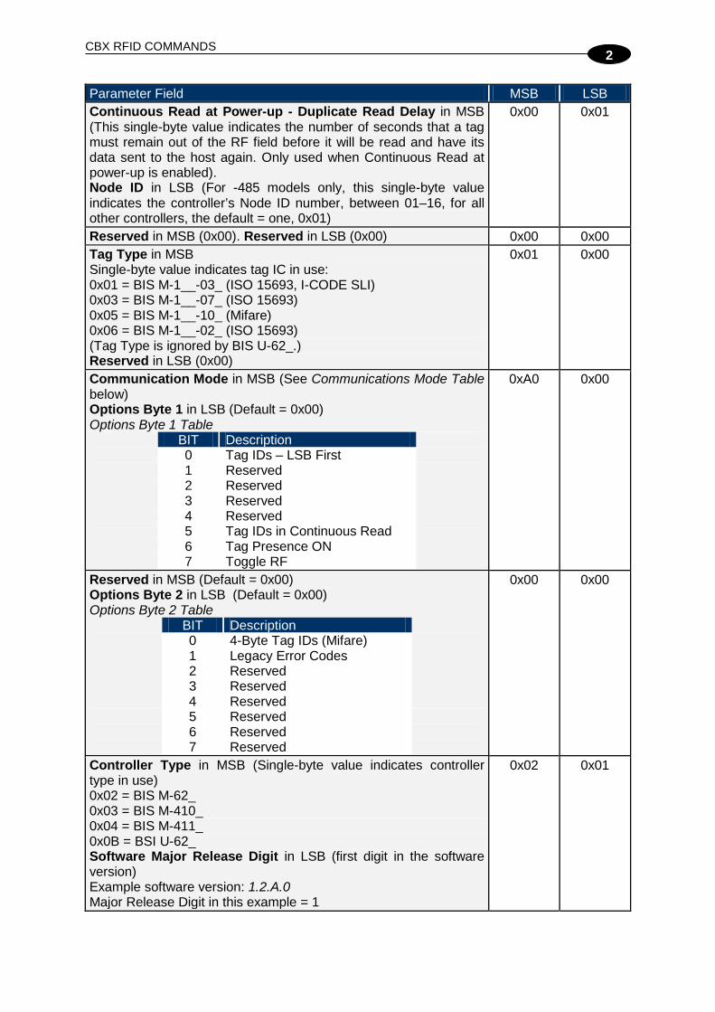
CBX RFID COMMANDS
2
Parameter Field MSB LSB Continuous Read at Power-up - Duplicate Read Delay in MSB (This single-byte value indicates the number of seconds that a tag must remain out of the RF field before it will be read and have its data sent to the host again. Only used when Continuous Read at power-up is enabled). Node ID in LSB (For -485 models only, this single-byte value indicates the controller’s Node ID number, between 01–16, for all other controllers, the default = one, 0x01)
0x00 0x01
Reserved in MSB (0x00). Reserved in LSB (0x00) 0x00 0x00 Tag Type in MSB Single-byte value indicates tag IC in use: 0x01 = BIS M-1__-03_ (ISO 15693, I-CODE SLI) 0x03 = BIS M-1__-07_ (ISO 15693) 0x05 = BIS M-1__-10_ (Mifare) 0x06 = BIS M-1__-02_ (ISO 15693) (Tag Type is ignored by BIS U-62_.) Reserved in LSB (0x00)
0x01 0x00
Communication Mode in MSB (See Communications Mode Table below) Options Byte 1 in LSB (Default = 0x00) Options Byte 1 Table
BIT Description 0 Tag IDs – LSB First 1 Reserved 2 Reserved 3 Reserved 4 Reserved 5 Tag IDs in Continuous Read 6 Tag Presence ON 7 Toggle RF
0xA0 0x00
Reserved in MSB (Default = 0x00) Options Byte 2 in LSB (Default = 0x00) Options Byte 2 Table
BIT Description 0 4-Byte Tag IDs (Mifare) 1 Legacy Error Codes 2 Reserved 3 Reserved 4 Reserved 5 Reserved 6 Reserved 7 Reserved
0x00 0x00
Controller Type in MSB (Single-byte value indicates controller type in use) 0x02 = BIS M-62_ 0x03 = BIS M-410_ 0x04 = BIS M-411_ 0x0B = BSI U-62_ Software Major Release Digit in LSB (first digit in the software version) Example software version: 1.2.A.0 Major Release Digit in this example = 1
0x02 0x01

CBX PROTOCOL REFERENCE MANUAL
60
2
Parameter Field MSB LSB Software Minor Release Digit in MSB (second digit in the software version) Example software version: 1.2.A.0 Minor Release Digit in this example = 2 Software Correction Release Digit in LSB (third digit in the software version) Example software version: 1.2.A.0 Correction Release Digit in this example = A
0x02 0x41
Software Point Release Digit in MSB (last digit(s) in the software version) Example software version: 1.2.A.0 Point Release Digit in this example = 0 0x00 in LSB
0x00 0x00
Communications Mode Table
BITS 7 6 5 4 3 2 1 0 0 Interface:
00 = RS422 01 = RS232 / USB 10 = RS485 11 = Others
Reserved
Baud Rate: 000 = 9600 001 = 19200 010 = 38400 011 = 57600 100 = 115200
1
Table 2-10: Communications Mode Table
NOTE
In the above example, the Communications Mode value of 0xA0 = 10100000 in binary, meaning that the controller is an RS485 device that is communicating at 9600 baud.

CBX RFID COMMANDS
2
CBX COMMAND 0X38: GET CONTROLLER INFO Command 0x38 - Description The Get Controller Info Command is used to retrieve hardware version, serial number and installed firmware identification information from the specified controller. Command 0x38 - CBx Example This example retrieves information from the controller at Node 01. Command from Host Parameter Field MSB LSB CBx Header in MSB, Node ID in LSB 0xFF 0x01 Overall Length of Command (in words) 0x00 0x06 0xAA in MSB. Command ID in LSB (0x38) 0xAA 0x38 0x00 in MSB, Node ID in LSB 0x00 0x01 Not Used: (default: 0x00, 0x00) 0x00 0x00 Not Used: (default: 0x00, 0x00) 0x00 0x00 Not Used: (default: 0x00, 0x00) 0x00 0x00
Response from Controller Parameter Field MSB LSB Overall Length of Response (in words) 0x00 0x13 0xAA in MSB, Command Echo in LSB 0xAA 0x38 Instance Counter in MSB. Node ID Echo in LSB <IC> 0x01 Month and Day Timestamp: (March 19th) 0x03 0x13 Hour and Minute Timestamp: (10:11: AM) 0x0A 0x0B Seconds Timestamp in MSB (:36 seconds). Additional Data Length in LSB
0x24 0x1A
Controller Type in MSB Single-byte value indicates controller type: 0x02 = BIS M-62_ 0x03 = BIS M-410_ 0x04 = BIS M-411_ 0x0B = BSI U-62_ Software Major Release Digit in LSB (First digit in the software version) Example software version: 1.2.A.0 Major Release Digit in this example = 1
0x02 0x01
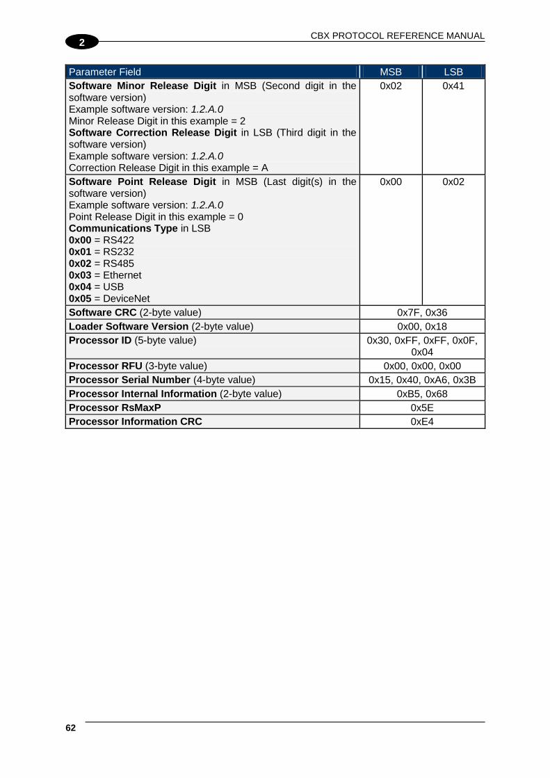
CBX PROTOCOL REFERENCE MANUAL
62
2
Parameter Field MSB LSB Software Minor Release Digit in MSB (Second digit in the software version) Example software version: 1.2.A.0 Minor Release Digit in this example = 2 Software Correction Release Digit in LSB (Third digit in the software version) Example software version: 1.2.A.0 Correction Release Digit in this example = A
0x02 0x41
Software Point Release Digit in MSB (Last digit(s) in the software version) Example software version: 1.2.A.0 Point Release Digit in this example = 0 Communications Type in LSB 0x00 = RS422 0x01 = RS232 0x02 = RS485 0x03 = Ethernet 0x04 = USB 0x05 = DeviceNet
0x00 0x02
Software CRC (2-byte value) 0x7F, 0x36 Loader Software Version (2-byte value) 0x00, 0x18 Processor ID (5-byte value) 0x30, 0xFF, 0xFF, 0x0F,
0x04 Processor RFU (3-byte value) 0x00, 0x00, 0x00 Processor Serial Number (4-byte value) 0x15, 0x40, 0xA6, 0x3B Processor Internal Information (2-byte value) 0xB5, 0x68 Processor RsMaxP 0x5E Processor Information CRC 0xE4
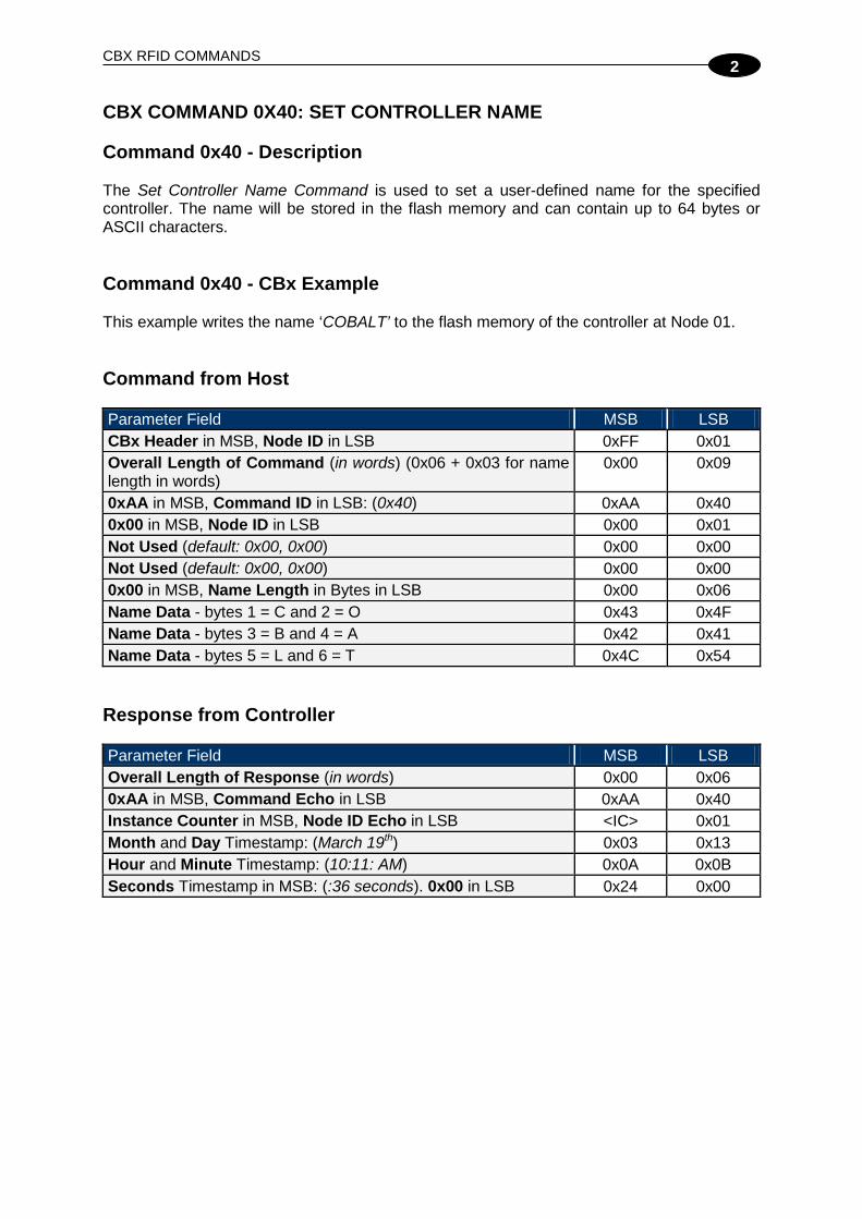
CBX RFID COMMANDS
2
CBX COMMAND 0X40: SET CONTROLLER NAME Command 0x40 - Description The Set Controller Name Command is used to set a user-defined name for the specified controller. The name will be stored in the flash memory and can contain up to 64 bytes or ASCII characters. Command 0x40 - CBx Example This example writes the name ‘COBALT’ to the flash memory of the controller at Node 01. Command from Host Parameter Field MSB LSB CBx Header in MSB, Node ID in LSB 0xFF 0x01 Overall Length of Command (in words) (0x06 + 0x03 for name length in words)
0x00 0x09
0xAA in MSB, Command ID in LSB: (0x40) 0xAA 0x40 0x00 in MSB, Node ID in LSB 0x00 0x01 Not Used (default: 0x00, 0x00) 0x00 0x00 Not Used (default: 0x00, 0x00) 0x00 0x00 0x00 in MSB, Name Length in Bytes in LSB 0x00 0x06 Name Data - bytes 1 = C and 2 = O 0x43 0x4F Name Data - bytes 3 = B and 4 = A 0x42 0x41 Name Data - bytes 5 = L and 6 = T 0x4C 0x54
Response from Controller Parameter Field MSB LSB Overall Length of Response (in words) 0x00 0x06 0xAA in MSB, Command Echo in LSB 0xAA 0x40 Instance Counter in MSB, Node ID Echo in LSB <IC> 0x01 Month and Day Timestamp: (March 19th) 0x03 0x13 Hour and Minute Timestamp: (10:11: AM) 0x0A 0x0B Seconds Timestamp in MSB: (:36 seconds). 0x00 in LSB 0x24 0x00

CBX PROTOCOL REFERENCE MANUAL
64
2
CBX COMMAND 0X43: SET CONTROLLER CONFIGURATION Command 0x43 - Description The Set Controller Configuration Command is used to modify and save changes to the controller’s configuration, which will be stored in the unit’s flash memory.
NOTE
It is recommended that the user first run the Command 0x33: "Get Controller Configuration" and make note of the current controller configuration values prior to executing this command.
Command 0x43 - CBx Example This example sets the following configuration parameters for the controller at Node 01. Command from Host Parameter Field MSB LSB CBx Header in MSB, Node ID in LSB 0xFF 0x01 Overall Length of Command (in words) 0x00 0x10 0xAA in MSB. Command ID in LSB: (0x43) 0xAA 0x43 0x00 in MSB, Node ID in LSB 0x00 0x01 Not Used (default: 0x00, 0x00) 0x00 0x00 Not Used (default: 0x00, 0x00) 0x00 0x00 Additional Data Length (in bytes) 0x00 0x13 Continuous Read at Power-up - Start Address: (Two-byte integer indicating the tag location where the read operation will begin when performing a continuous read at power-up or reset, default: 0x0000 = begin read at first available byte)
0x00 0x00
Continuous Read at Power-up - Block Size: (Two-byte integer indicating the number of bytes to retrieve when performing a continuous read at power-up or reset. Any value greater than zero instructs the controller to enter continuous read mode the next time it powers-up or is reset. When this value is set to zero, the controller will not enter continuous read mode at power-up or reset, default = 0x0000)
0x00 0x00
Continuous Read at Power-up - Duplicate Read Delay in MSB: (Single-byte value indicates the number of seconds that a tag must remain out of RF range before it can be re-read and its data sent to the host again. Only applicable when Block Size ≥ one, thereby enabling continuous read at power-up, default: 0x00) Node ID in LSB (For -485 models only, this single-byte value indicates the controller’s Node ID number, between 01–16, for all other controllers, the default = one, 0x01)
0x00 0x01
Reserved (default value: 0x00, 0x00) 0x00 0x00

CBX RFID COMMANDS
2
Parameter Field MSB LSB Tag Type in MSB: (Single-byte value indicates type of tag integrated circuit to recognize). 0x01 = BIS M-1__-03_ (ISO 15693, I-CODE SLI) 0x03 = BIS M-1__-07_ (ISO 15693) 0x05 = BIS M-1__-10_ (Mifare) 0x06 = BIS M-1__-02_ (ISO 15693) (Tag Type is ignored by BIS U-62_.) Reserved in LSB (default: 0x00)
0x01 0x00
Communication Mode in MSB (See Communications Mode Table below) Options Byte 1 in LSB Options Byte 1 Table
BIT Description 0 Tag IDs – LSB First 1 Reserved 2 Reserved 3 Reserved 4 Reserved 5 Tag IDs in Continuous Read 6 Tag Presence ON 7 Toggle RF
0xA0 0x00
Reserved in MSB (default: 0x00) Options Byte 2 in LSB Options Byte 2 Table
BIT Description 0 4-Byte Tag IDs (Mifare) 1 Legacy Error Codes 2 Reserved 3 Reserved 4 Reserved 5 Reserved 6 Reserved 7 Reserved
0x00 0x00
Controller Type in MSB: Software Major Release Digit in LSB
0x02 0x01
Software Minor Release Digit in MSB Correction Release Digit in LSB
0x02 0x41
Software Point Release Digit in MSB 0x00 in LSB
0x00 0x00
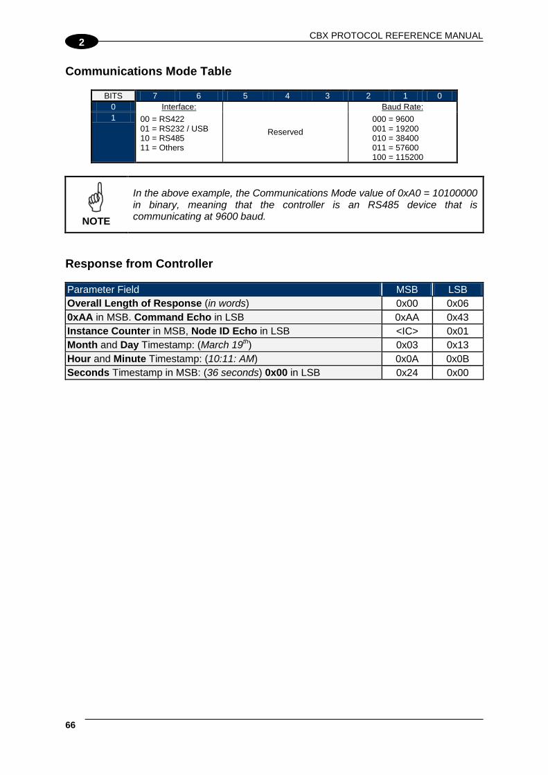
CBX PROTOCOL REFERENCE MANUAL
66
2
Communications Mode Table
BITS 7 6 5 4 3 2 1 0 0 Interface:
00 = RS422 01 = RS232 / USB 10 = RS485 11 = Others
Reserved
Baud Rate: 000 = 9600 001 = 19200 010 = 38400 011 = 57600 100 = 115200
1
NOTE
In the above example, the Communications Mode value of 0xA0 = 10100000 in binary, meaning that the controller is an RS485 device that is communicating at 9600 baud.
Response from Controller Parameter Field MSB LSB Overall Length of Response (in words) 0x00 0x06 0xAA in MSB. Command Echo in LSB 0xAA 0x43 Instance Counter in MSB, Node ID Echo in LSB <IC> 0x01 Month and Day Timestamp: (March 19th) 0x03 0x13 Hour and Minute Timestamp: (10:11: AM) 0x0A 0x0B Seconds Timestamp in MSB: (36 seconds) 0x00 in LSB 0x24 0x00

CBX RFID COMMANDS
2
CBX COMMAND 0X4E: SET CONTROLLER TIME Command 0x4E - Description The Set Controller Time Command is used to set the controller’s internal clock and calendar. Date and Time are specified in the following format: • Year MSB:LSB (2-byte Integer) • Month (byte), Day of Month (byte) • Hour (byte), Minute (byte) • Seconds (byte), 0x00 Command 0x4E - CBx Example This example sets the date and time on the controller to March 19, 2007 - 9:30 a.m. Command from Host Parameter Field MSB LSB CBx Header in MSB, Node ID in LSB 0xFF 0x01 Overall Length of Command (in words) 0x00 0x0A 0xAA in MSB. Command ID in LSB: (0x4E) 0xAA 0x4E 0x00 in MSB, Node ID in LSB 0x00 0x01 Not Used (default: 0x00, 0x00) 0x00 0x00 Not Used (default: 0x00, 0x00) 0x00 0x00 Time/Date Data Length (7 bytes) 0x00 0x07 Year: (2007) 0x07 0xD7 Month and Day 0x03 0x13 Hour and Minute 0x09 0x1E Seconds in MSB. 0x00 in LSB 0x00 0x00
Response from Controller Parameter Field MSB LSB Overall Length of Response (in words) 0x00 0x06 0xAA in MSB. Command Echo in LSB 0xAA 0x4E Instance Counter in MSB. Node Echo in LSB <IC> 0x01 Month and Day Timestamp: (March 19th) 0x03 0x13 Hour and Minute Timestamp: (9:30: AM) 0x09 0x1E Seconds Timestamp in MSB: (03 seconds) 0x00 in LSB 0x03 0x00

CBX PROTOCOL REFERENCE MANUAL
68
2
CBX COMMAND 0X53: INITIALIZE CONTROLLER Command 0x53 - Description The Initialize Controller Command removes all stored information from the specified controller, including all configuration, macro and trigger data. The controller’s Node ID number will be physically reconfigured to factory defaults as well. Command 0x53 - CBx Example This example will remove all stored information from the controller at Node 01. Command from Host Parameter Field MSB LSB CBx Header in MSB, Node ID in LSB 0xFF 0x01 Overall Length of Command (in words) 0x00 0x06 0xAA in MSB, Command ID in LSB: (0x53) 0xAA 0x53 0x00 in MSB, Node ID in LSB 0x00 0x01 Not Used (default: 0x00, 0x00) 0x00 0x00 Not Used (default: 0x00, 0x00) 0x00 0x00 Not Used (default: 0x00, 0x00) 0x00 0x00
Response from Controller Parameter Field MSB LSB Overall Length of Response (in words) 0x00 0x06 0xAA in MSB. Command Echo in LSB 0xAA 0x53 Instance Counter in MSB. Node ID Echo in LSB <IC> 0x01 Month and Day Timestamp: (March 19th) 0x03 0x13 Hour and Minute Timestamp: (10:11: AM) 0x0A 0x0B Seconds Timestamp in MSB: (36 seconds). 0x00 in LSB 0x24 0x00

CBX RFID COMMANDS
2
CBX COMMAND 0X54: RESET CONTROLLER Command 0x54 - Description The Reset Controller Command is used to reset power to the specified controller without clearing any stored configuration information. However, the controller’s configuration can be reset to default values when Command 0x54 is issued AND a Configuration Tag is placed in the antenna’s RF field prior to execution. Command 0x54 - CBx Example This example resets power to the controller at Node 01. Command from Host Parameter Field MSB LSB CBx Header in MSB, Node ID in LSB 0xFF 0x01 Overall Length of Command (in words) 0x00 0x06 0xAA in MSB. Command ID in LSB: (0x54) 0xAA 0x54 0x00 in MSB, Node ID in LSB 0x00 0x01 Not Used (default: 0x00, 0x00) 0x00 0x00 Not Used (default: 0x00, 0x00) 0x00 0x00 Not Used (default: 0x00, 0x00) 0x00 0x00
Response from Controller Parameter Field MSB LSB Overall Length of Response (in words) 0x00 0x06 0xAA in MSB, Command Echo in LSB 0xAA 0x54 Instance Counter in MSB. Node ID Echo in LSB <IC> 0x01 Month and Day Timestamp: (March 19th) 0x03 0x13 Hour and Minute Timestamp: (10:11: AM) 0x0A 0x0B Seconds Timestamp in MSB: (:36 seconds). 0x00 in LSB 0x24 0x00
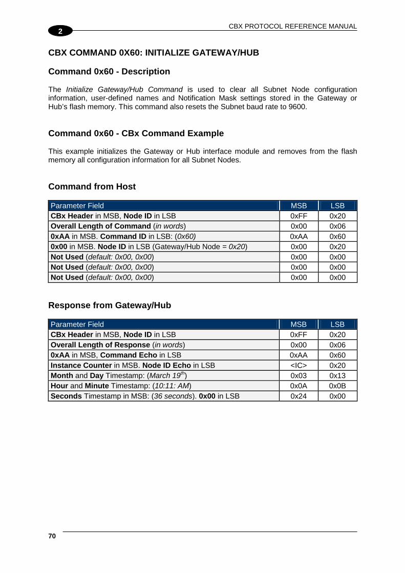
CBX PROTOCOL REFERENCE MANUAL
70
2
CBX COMMAND 0X60: INITIALIZE GATEWAY/HUB Command 0x60 - Description The Initialize Gateway/Hub Command is used to clear all Subnet Node configuration information, user-defined names and Notification Mask settings stored in the Gateway or Hub’s flash memory. This command also resets the Subnet baud rate to 9600. Command 0x60 - CBx Command Example This example initializes the Gateway or Hub interface module and removes from the flash memory all configuration information for all Subnet Nodes. Command from Host Parameter Field MSB LSB CBx Header in MSB, Node ID in LSB 0xFF 0x20 Overall Length of Command (in words) 0x00 0x06 0xAA in MSB. Command ID in LSB: (0x60) 0xAA 0x60 0x00 in MSB. Node ID in LSB (Gateway/Hub Node = 0x20) 0x00 0x20 Not Used (default: 0x00, 0x00) 0x00 0x00 Not Used (default: 0x00, 0x00) 0x00 0x00 Not Used (default: 0x00, 0x00) 0x00 0x00
Response from Gateway/Hub Parameter Field MSB LSB CBx Header in MSB, Node ID in LSB 0xFF 0x20 Overall Length of Response (in words) 0x00 0x06 0xAA in MSB, Command Echo in LSB 0xAA 0x60 Instance Counter in MSB. Node ID Echo in LSB <IC> 0x20 Month and Day Timestamp: (March 19th) 0x03 0x13 Hour and Minute Timestamp: (10:11: AM) 0x0A 0x0B Seconds Timestamp in MSB: (36 seconds). 0x00 in LSB 0x24 0x00

CBX RFID COMMANDS
2
CBX COMMAND 0X61: RESET GATEWAY/HUB Command 0x61 - Description The Reset Gateway/Hub Command is used to perform a soft (electrical) reset of the Gateway or Hub interface module. The device will behave as if it had just powered up. If dipswitch 1 is ON (its default setting), the unit will automatically begin scanning all Subnet Nodes for attached RFID controllers. Command 0x61 - CBx Example This example resets the Gateway/Hub interface module. Command from Host Parameter Field MSB LSB CBx Header in MSB, Node ID in LSB 0xFF 0x20 Overall Length of Command (in words) 0x00 0x06 0xAA in MSB. Command ID in LSB: (0x60) 0xAA 0x61 0x00 in MSB.Node ID in LSB (Gateway/Hub Node = 0x20) 0x00 0x20 Not Used (default: 0x00, 0x00) 0x00 0x00 Not Used (default: 0x00, 0x00) 0x00 0x00 Not Used (default: 0x00, 0x00) 0x00 0x00
Response from Gateway/Hub Parameter Field MSB LSB CBx Header in MSB, Node ID in LSB 0xFF 0x20 Overall Length of Response (in words) 0x00 0x06 0xAA in MSB, Command Echo in LSB 0xAA 0x61 Instance Counter in MSB. Node ID Echo in LSB <IC> 0x20 Month and Day Timestamp: (March 19th) 0x03 0x13 Hour and Minute Timestamp: (10:11: AM) 0x0A 0x0B Seconds Timestamp in MSB: (36 seconds). 0x00 in LSB 0x24 0x00

CBX PROTOCOL REFERENCE MANUAL
72
2
CBX COMMAND 0X62: INITIALIZE ALL NODES Command 0x62 - Description The Initialize All Nodes Commands removes from the Gateway or Hub interface module all stored configuration information for all Subnet Nodes. Subnet Nodes will be reconfigured to factory defaults. Command 0x62 - CBx Example This example initializes all controllers on the Subnet network, thereby removing all stored configuration information and restoring factory default settings to all controllers. Command from Host Parameter Field MSB LSB CBx Header in MSB, Node ID in LSB 0xFF 0x20 Overall Length of Command (in words) 0x00 0x06 0xAA in MSB. Command ID in LSB: (0x60) 0xAA 0x62 0x00 in MSB. Node ID in LSB (Gateway/Hub Node = 0x20) 0x00 0x20 Not Used (default: 0x00, 0x00) 0x00 0x00 Not Used (default: 0x00, 0x00) 0x00 0x00 Not Used (default: 0x00, 0x00) 0x00 0x00
Response from Gateway/Hub Parameter Field MSB LSB CBx Header in MSB, Node ID in LSB 0xFF 0x20 Overall Length of Response (in words) 0x00 0x06 0xAA in MSB, Command Echo in LSB 0xAA 0x62 Instance Counter in MSB. Node ID Echo in LSB <IC> 0x20 Month and Day Timestamp: (March 19th) 0x03 0x13 Hour and Minute Timestamp: (10:11: AM) 0x0A 0x0B Seconds Timestamp in MSB: (36 seconds). 0x00 in LSB 0x24 0x00

CBX RFID COMMANDS
2
CBX COMMAND 0X63: INITIALIZE ALL NODE MACROS Command 0x63 - Description The Initialize All Node Macros Command initializes (removes) from memory all stored macros from all Subnet Nodes. Command 0x63 - CBx Example This example removes all macros from the Gateway/Hub’s internal memory as well as from any connected controllers on the Subnet network. Command from Host Parameter Field MSB LSB CBx Header in MSB, Node ID in LSB 0xFF 0x20 Overall Length of Command (in words) 0x00 0x06 0xAA in MSB, Command ID in LSB: (0x60) 0xAA 0x63 0x00 in MSB, Node ID in LSB (Gateway/Hub Node = 0x20) 0x00 0x20 Not Used (default: 0x00, 0x00) 0x00 0x00 Not Used (default: 0x00, 0x00) 0x00 0x00 Not Used (default: 0x00, 0x00) 0x00 0x00
Response from Gateway/Hub Parameter Field MSB LSB CBx Header in MSB, Node ID in LSB 0xFF 0x20 Overall Length of Response (in words) 0x00 0x06 0xAA in MSB, Command Echo in LSB 0xAA 0x63 Instance Counter in MSB, Node ID Echo in LSB <IC> 0x20 Month and Day Timestamp: (March 19th) 0x03 0x13 Hour and Minute Timestamp: (10:11: AM) 0x0A 0x0B Seconds Timestamp in MSB: (36 seconds). 0x00 in LSB 0x24 0x00

CBX PROTOCOL REFERENCE MANUAL
74
2
CBX COMMAND 0X70: START SUBNET Command 0x70 - Description The Start Subnet Command instructs the Gateway/Hub to begin “polling” the Subnet network. Initiating this command is only required when dipswitch 1 on the Gateway/Hub is set to OFF. With dipswitch 1 in the OFF position, the Gateway/Hub will not automatically begin polling Subnet Nodes upon power-up. Setting dipswitch 1 to OFF is a means of forcing the Gateway/Hub to wait until a connection with the host has been established. This is useful when it is desired that the Gateway/Hub NOT poll controllers until a host-initiated connection exists. Command 0x70 - CBx Example This example starts the Subnet, which instructs the Gateway/Hub to begin “polling” all connected controllers on the Subnet network. Command from Host Parameter Field MSB LSB CBx Header in MSB, Node ID in LSB 0xFF 0x20 Overall Length of Command (in words) 0x00 0x06 0xAA in MSB, Command ID in LSB: (0x60) 0xAA 0x70 0x00 in MSB, Node ID in LSB (Gateway/Hub Node = 0x20) 0x00 0x20 Not Used (default: 0x00, 0x00) 0x00 0x00 Not Used (default: 0x00, 0x00) 0x00 0x00 Not Used (default: 0x00, 0x00) 0x00 0x00
Response from Gateway/Hub Parameter Field MSB LSB CBx Header in MSB, Node ID in LSB 0xFF 0x20 Overall Length of Response (in words) 0x00 0x06 0xAA in MSB, Command Echo in LSB 0xAA 0x70 Instance Counter in MSB, Node ID Echo in LSB <IC> 0x20 Month and Day Timestamp: (March 19th) 0x03 0x13 Hour and Minute Timestamp:(10:11: AM) 0x0A 0x0B Seconds Timestamp in MSB (36 seconds), 0x00 in LSB 0x24 0x00
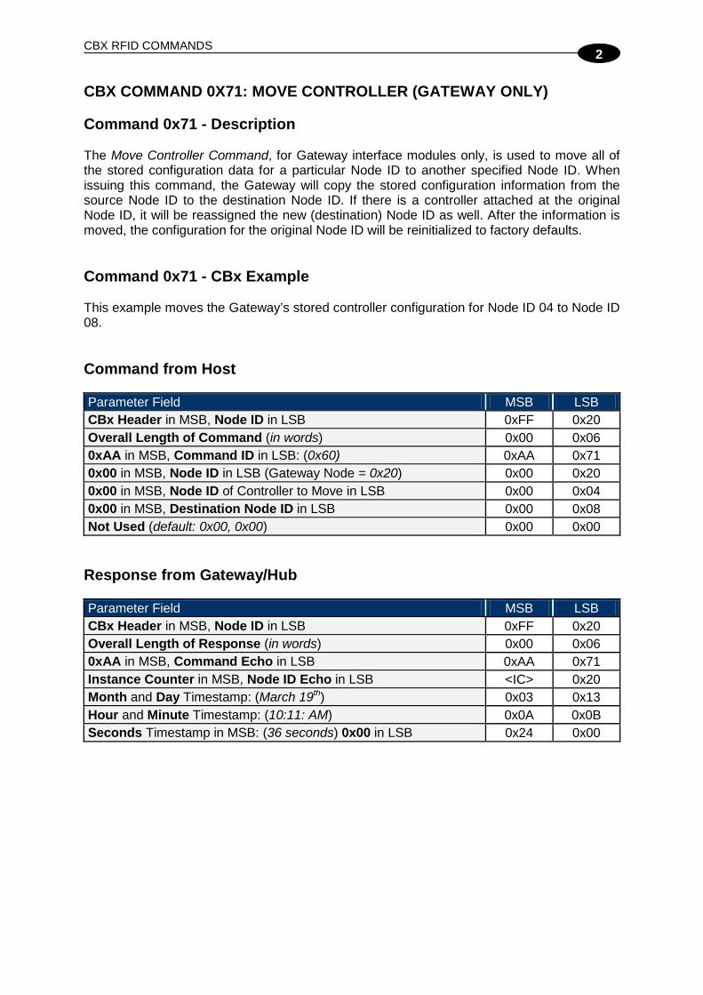
CBX RFID COMMANDS
2
CBX COMMAND 0X71: MOVE CONTROLLER (GATEWAY ONLY) Command 0x71 - Description The Move Controller Command, for Gateway interface modules only, is used to move all of the stored configuration data for a particular Node ID to another specified Node ID. When issuing this command, the Gateway will copy the stored configuration information from the source Node ID to the destination Node ID. If there is a controller attached at the original Node ID, it will be reassigned the new (destination) Node ID as well. After the information is moved, the configuration for the original Node ID will be reinitialized to factory defaults. Command 0x71 - CBx Example This example moves the Gateway’s stored controller configuration for Node ID 04 to Node ID 08. Command from Host Parameter Field MSB LSB CBx Header in MSB, Node ID in LSB 0xFF 0x20 Overall Length of Command (in words) 0x00 0x06 0xAA in MSB, Command ID in LSB: (0x60) 0xAA 0x71 0x00 in MSB, Node ID in LSB (Gateway Node = 0x20) 0x00 0x20 0x00 in MSB, Node ID of Controller to Move in LSB 0x00 0x04 0x00 in MSB, Destination Node ID in LSB 0x00 0x08 Not Used (default: 0x00, 0x00) 0x00 0x00
Response from Gateway/Hub Parameter Field MSB LSB CBx Header in MSB, Node ID in LSB 0xFF 0x20 Overall Length of Response (in words) 0x00 0x06 0xAA in MSB, Command Echo in LSB 0xAA 0x71 Instance Counter in MSB, Node ID Echo in LSB <IC> 0x20 Month and Day Timestamp: (March 19th) 0x03 0x13 Hour and Minute Timestamp: (10:11: AM) 0x0A 0x0B Seconds Timestamp in MSB: (36 seconds) 0x00 in LSB 0x24 0x00

CBX PROTOCOL REFERENCE MANUAL
76
2
CBX COMMAND 0X79: CLEAR PENDING RESPONSES Command 0x79 - Description The Clear Pending Response Command deletes all pending or buffered responses in the Gateway/Hub and resets all Instance Counters for all nodes, including the Gateway/Hub, to zero (0x00). Command 0x79 - CBx Example This example removes any pending response data from the Gateway/Hub and resets the Instance Counter values for all nodes (including the Gateway/Hub) to zero. Command from Host Parameter Field MSB LSB CBx Header in MSB, Node ID in LSB 0xFF 0x20 Overall Length of Command (in words) 0x00 0x06 0xAA in MSB. Command ID in LSB: (0x60) 0xAA 0x79 0x00 in MSB. Node ID in LSB (Gateway/Hub Node = 0x20) 0x00 0x20 Not Used (default: 0x00, 0x00) 0x00 0x00 Not Used (default: 0x00, 0x00) 0x00 0x00 Not Used (default: 0x00, 0x00) 0x00 0x00
Response from Gateway/Hub Parameter Field MSB LSB CBx Header in MSB, Node ID in LSB 0xFF 0x20 Overall Length of Response (in words) 0x00 0x06 0xAA in MSB, Command Echo in LSB 0xAA 0x79 Instance Counter in MSB, Node ID Echo in LSB <IC> 0x20 Month and Day Timestamp: (March 19th) 0x03 0x13 Hour and Minute Timestamp: (10:11: AM) 0x0A 0x0B Seconds Timestamp in MSB: (36 seconds). 0x00 in LSB 0x24 0x00

CBX RFID COMMANDS
2
CBX COMMAND 0X92: MULTI-TAG READ ID AND DATA ALL Command 0x92 - Description The Multi-Tag Read ID and Data All Command is used to retrieve the tag ID and a contiguous segment of data from all RFID tags in range (or those with the specified AFI). The controller will generate separate responses containing the tag ID and the requested data for each responding tag. Each response packet will be sent to the host as soon as it is available. The returned tag IDs can be used to read from/write to a single tag (via the Multi-Tag Block Read/Write by ID commands) when multiple tags are identified simultaneously. A final termination packet is sent when the Timeout Value expires. When the Start Address is set to zero (0x0000), the controller will start reading at the beginning (or first accessible byte) of the tag. If the Block Size exceeds the last tag address, the controller will return an error message. Command 0x92 - CBx Example This example instructs the controller at Node 01 to read the tag ID and 16 bytes of data from each tag in range starting at address 0x0001. A Timeout Value of 3 seconds (0x0BB8 = 3000 x 1msec increments) is set for the completion of the command. The AFI byte is set to zero so that all tags in range will respond. Command from Host Parameter Field MSB LSB CBx Header in MSB, Node ID in LSB 0xFF 0x01 Overall Length of Command (in words) 0x00 0x08 0xAA in MSB, Command ID in LSB 0xAA 0x92 0x00 in MSB . Node ID in LSB 0x00 0x01 Timeout Value 0x0B 0xB8 Start Address 0x00 0x01 Block Size 0x00 0x10 AFI in MSB. Anti-Collision Mode in LSB 0x00 0x01 Tag Limit in MSB. 0x00 in LSB 0x64 0x00

CBX PROTOCOL REFERENCE MANUAL
78
2
Response from Controller (for Each Tag Found) Parameter Field MSB LSB
Overall Length of Response (in words) 0x00
0x06 + number of
words retrieved
0xAA in MSB, Command Echo in LSB 0xAA 0x92 Instance Counter in MSB Node ID Echo in LSB <IC> 0x01
Month and Day Timestamp <Month> <Day> Hour and Minute Timestamp <Hour> <Min> Seconds Timestamp Additional Data Length (24 additional bytes returned, includes both ID and Data)
<Sec> 0x18
Tag ID (bytes 1 and 2) <Tag ID B1> <Tag ID B2> Tag ID (bytes 3 and 4) <Tag ID B3> <Tag ID B4> Tag ID (bytes 5 and 6) <Tag ID B5> <Tag ID B6> Tag ID (bytes 7 and 8) <Tag ID B7> <Tag ID B8> Returned Data (bytes 1 and 2) <D1> <D2> Returned Data (bytes 3 and 4) <D3> <D4> … … … Returned Data (bytes 15 and 16) <D15> <D16>
Final Response Packet Parameter Field MSB LSB Overall Length of Response (in words) 0x00 0x07 0xAA in MSB, 0xFF in LSB 0xAA 0xFF Instance Counter in MSB Node ID Echo in LSB
<IC> 0x01
Month and Day Timestamp <Month> <Day> Hour and Minute Timestamp <Hour> <Min> Seconds Timestamp Additional Data Length (2 bytes: “Number of Tags” and “Status”)
<Sec> 0x02
Number of Tags Read in MSB Status in LSB: 0x00 = operation completed successfully, 0x07 = Read Tag ID failed / Tag Not Found
<# of tags read>
0x00

CBX RFID COMMANDS
2
CBX COMMAND 0X95: MULTI-TAG BLOCK READ ALL Command 0x95 - Description The Multi-Tag Block Read All Command is used to retrieve a contiguous segment of data from all RFID tags within RF range (or those with the specified AFI). The controller will generate separate responses containing the requested data for each responding tag. Each response packet will be sent to the host as soon as it is available. A final termination packet is sent when the Timeout Value expires. When the Start Address is set to zero (0x0000), the controller will start reading at the beginning (or first accessible byte) of the tag. If the Block Size exceeds the last tag address, the controller will return an error message. Command 0x95 - CBx Example This example instructs the controller to read 16 bytes of data from each tag in range starting at address 0x0001. A Timeout Value of 3 seconds (0x0BB8 = 3000 x 1msec increments) is set for the completion of the command. The AFI byte is set to zero so all tags in range will respond. Command from Host Parameter Field MSB LSB CBx Header in MSB, Node ID in LSB 0xFF 0x01 Overall Length of Command (in words) 0x00 0x08 0xAA in MSB, Command ID in LSB 0xAA 0x95 0x00 in MSB. Node ID in LSB 0x00 0x01 Timeout Value 0x0B 0xB8 Start Address 0x00 0x01 Block Size 0x00 0x10 AFI in MSB. Anti-Collision Mode in LSB 0x00 0x01 Tag Limit in MSB. 0x00 in LSB 0x64 0x00
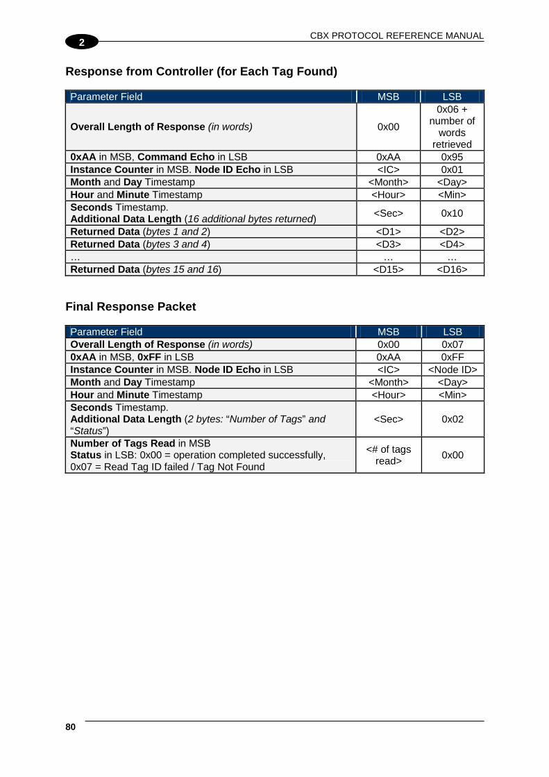
CBX PROTOCOL REFERENCE MANUAL
80
2
Response from Controller (for Each Tag Found) Parameter Field MSB LSB
Overall Length of Response (in words) 0x00
0x06 + number of
words retrieved
0xAA in MSB, Command Echo in LSB 0xAA 0x95 Instance Counter in MSB. Node ID Echo in LSB <IC> 0x01 Month and Day Timestamp <Month> <Day> Hour and Minute Timestamp <Hour> <Min> Seconds Timestamp. Additional Data Length (16 additional bytes returned) <Sec> 0x10
Returned Data (bytes 1 and 2) <D1> <D2> Returned Data (bytes 3 and 4) <D3> <D4> … … … Returned Data (bytes 15 and 16) <D15> <D16>
Final Response Packet Parameter Field MSB LSB Overall Length of Response (in words) 0x00 0x07 0xAA in MSB, 0xFF in LSB 0xAA 0xFF Instance Counter in MSB. Node ID Echo in LSB <IC> <Node ID> Month and Day Timestamp <Month> <Day> Hour and Minute Timestamp <Hour> <Min> Seconds Timestamp. Additional Data Length (2 bytes: “Number of Tags” and “Status”)
<Sec> 0x02
Number of Tags Read in MSB Status in LSB: 0x00 = operation completed successfully, 0x07 = Read Tag ID failed / Tag Not Found
<# of tags read> 0x00
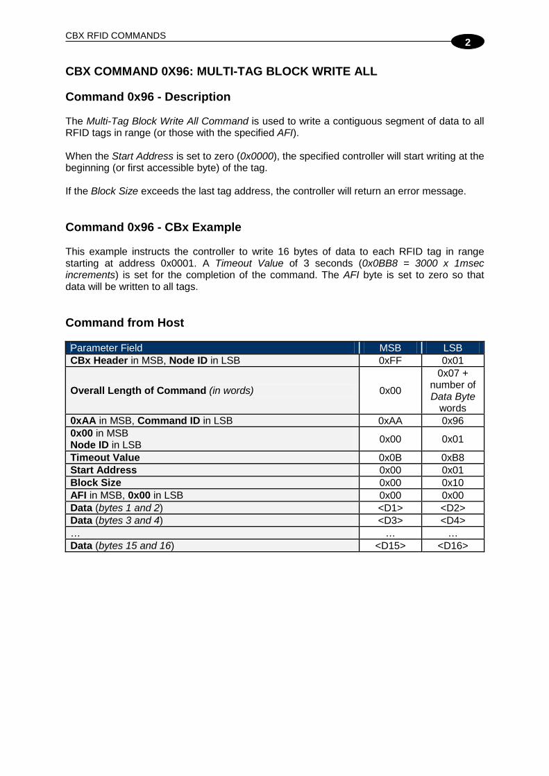
CBX RFID COMMANDS
2
CBX COMMAND 0X96: MULTI-TAG BLOCK WRITE ALL Command 0x96 - Description The Multi-Tag Block Write All Command is used to write a contiguous segment of data to all RFID tags in range (or those with the specified AFI). When the Start Address is set to zero (0x0000), the specified controller will start writing at the beginning (or first accessible byte) of the tag. If the Block Size exceeds the last tag address, the controller will return an error message. Command 0x96 - CBx Example This example instructs the controller to write 16 bytes of data to each RFID tag in range starting at address 0x0001. A Timeout Value of 3 seconds (0x0BB8 = 3000 x 1msec increments) is set for the completion of the command. The AFI byte is set to zero so that data will be written to all tags. Command from Host Parameter Field MSB LSB CBx Header in MSB, Node ID in LSB 0xFF 0x01
Overall Length of Command (in words) 0x00
0x07 + number of Data Byte
words 0xAA in MSB, Command ID in LSB 0xAA 0x96 0x00 in MSB Node ID in LSB 0x00 0x01
Timeout Value 0x0B 0xB8 Start Address 0x00 0x01 Block Size 0x00 0x10 AFI in MSB, 0x00 in LSB 0x00 0x00 Data (bytes 1 and 2) <D1> <D2> Data (bytes 3 and 4) <D3> <D4> … … … Data (bytes 15 and 16) <D15> <D16>
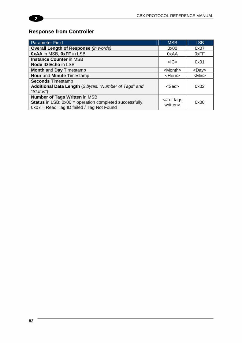
CBX PROTOCOL REFERENCE MANUAL
82
2
Response from Controller Parameter Field MSB LSB Overall Length of Response (in words) 0x00 0x07 0xAA in MSB, 0xFF in LSB 0xAA 0xFF Instance Counter in MSB Node ID Echo in LSB <IC> 0x01
Month and Day Timestamp <Month> <Day> Hour and Minute Timestamp <Hour> <Min> Seconds Timestamp Additional Data Length (2 bytes: “Number of Tags” and “Status”)
<Sec> 0x02
Number of Tags Written in MSB Status in LSB: 0x00 = operation completed successfully, 0x07 = Read Tag ID failed / Tag Not Found
<# of tags written> 0x00

CBX RFID COMMANDS
2
CBX COMMAND 0X97: MULTI-TAG GET INVENTORY Command 0x97 - Description The Multi-Tag Get Inventory Command is used to retrieve the tag ID from all RFID tags in range (or those with the specified AFI). Each tag has a unique Tag ID or Serial Number. This number cannot be changed and is not considered part of the tag’s available memory. The controller will generate separate responses containing the tag ID for each responding tag. Each response packet will be sent to the host as soon as it is available. The returned tag IDs can be used to read from/write to a single tag (via the Multi-Tag Block Read/Write by ID commands) when multiple tags are identified simultaneously. A final termination packet is sent when the Timeout Value expires. Command 0x97 - CBx Example This example instructs the controller to read the tag ID from each tag in range. A Timeout Value of 3 seconds (0x0BB8 = 3000 x 1msec increments) is set for the completion of the command. The AFI byte is set to zero so all tags in range will respond. Command from Host Parameter Field MSB LSB CBx Header in MSB, Node ID in LSB 0xFF 0x01 Overall Length of Command (in words) 0x00 0x08 0xAA in MSB, Command ID in LSB 0xAA 0x97 0x00 in MSB. Node ID in LSB 0x00 0x01 Timeout Value 0x0B 0xB8 Start Address 0x00 0x00 Block Size 0x00 0x00 AFI in MSB. Anti-Collision Mode in LSB 0x00 0x01 Tag Limit in MSB, 0x00 in LSB 0x64 0x00

CBX PROTOCOL REFERENCE MANUAL
84
2
Response from Controller (for Each Tag Found) Parameter Field MSB LSB Overall Length of Response (in words) 0x00 0x0A 0xAA in MSB, Command Echo in LSB 0xAA 0x97 Instance Counter in MSB. Node ID Echo in LSB <IC> 0x01 Month and Day Timestamp <Month> <Day> Hour and Minute Timestamp <Hour> <Min> Seconds Timestamp in MSB. Additional Data Length in LSB (8 additional bytes returned) <Sec> 0x08
Tag ID (bytes 1 and 2) <ID1> <ID2> Tag ID (bytes 3 and 4) <ID3> <ID4> Tag ID (bytes 5 and 6) <ID5> <ID6> Tag ID (bytes 7 and 8) <ID7> <ID8>
Final Response Packet Parameter Field MSB LSB Overall Length of Response (in words) 0x00 0x07 0xAA in MSB, 0xFF in LSB 0xAA 0xFF Instance Counter in MSB. Node ID Echo in LSB <IC> 0x01 Month and Day Timestamp <Month> <Day> Hour and Minute Timestamp <Hour> <Min> Seconds Timestamp in MSB. Additional Data Length in LSB (2 bytes: “Number of Tags” and “Status”)
<Sec> 0x02
Number of Tags Found in MSB Status in LSB: 0x00 = operation completed successfully, 0x07 = Read Tag ID failed / Tag Not Found
<# of tags found> 0x00

CBX RFID COMMANDS
2
CBX COMMAND 0X98: MULTI-TAG SEARCH ALL Command 0x98 - Description The Multi-Tag Search All Command is used to check for the presence of RFID tags in the antenna field. As soon as the controller finds a tag, it will return a response to the host. If no tags are present, and the Timeout Value has expired, the controller will return an error. Command 0x98 - CBx Example This example instructs the controller to search for the presence of any RFID tag in range. A Timeout Value of 3 seconds (0x0BB8 = 3000 x 1msec increments) is set for the completion of the command. The AFI byte is set to zero so all tags in range will respond. Command from Host Parameter Field MSB LSB CBx Header in MSB, Node ID in LSB 0xFF 0x01 Overall Length of Command (in words) 0x00 0x08 0xAA in MSB, Command ID in LSB 0xAA 0x98 0x00 in MSB, Node ID in LSB 0x00 0x01 Timeout Value 0x0B 0xB8 Start Address 0x00 0x00 Block Size 0x00 0x00 AFI in MSB. Anti-Collision Mode in LSB 0x00 0x01 Tag Limit in MSB, 0x00 in LSB 0x64 0x00
Response from Controller Parameter Field MSB LSB Overall Length of Response (in words) 0x00 0x07 0xAA in MSB, 0xFF in LSB 0xAA 0xFF Instance Counter in MSB Node ID Echo in LSB <IC> 0x01
Month and Day Timestamp <Month> <Day> Hour and Minute Timestamp <Hour> <Min> Seconds Timestamp in MSB Additional Data Length in LSB (2 bytes: “Number of Tags” and “Status”)
<Sec> 0x02
Number of Tags Found in MSB Status in LSB: 0x00 = operation successful, 0x07 = Tag Not Found
<# of tags found> 0x00

CBX PROTOCOL REFERENCE MANUAL
86
2
CBX COMMAND 0XA5: MULTI-TAG BLOCK READ BY ID Command 0xA5 - Description The Multi-Tag Block Read by ID Command is used to read a contiguous segment of data from a specific RFID tag identified by its tag ID. An error packet is sent if the specific tag is not present and the Timeout Value expires. When the Start Address is set to zero (0x0000), the controller will start reading at the beginning (or first accessible byte) of the tag. If the Block Size exceeds the last tag address, the controller will return an error message. Command 0xA5 - CBx Example This example instructs the controller to read 16 bytes of data from the tag containing the specified tag ID, beginning at tag address 0x0001. A Timeout Value of 3 seconds (0x0BB8 = 3000 x 1msec increments) is set for the completion of the command. Command from Host Parameter Field MSB LSB CBx Header in MSB, Node ID in LSB 0xFF 0x01 Overall Length of Command (in words) 0x00 0x0B 0xAA in MSB, Command ID in LSB 0xAA 0xA5 0x00 in MSB. Node ID in LSB 0x00 0x01 Timeout Value 0x0B 0xB8 Start Address 0x00 0x01 Block Size 0x00 0x10 AFI in MSB, 0x00 in LSB 0x00 0x00 Tag ID (bytes 1 and 2) <ID1> <ID2> Tag ID (bytes 3 and 4) <ID3> <ID4> Tag ID (bytes 5 and 6) <ID5> <ID6> Tag ID (bytes 7 and 8) <ID7> <ID8>
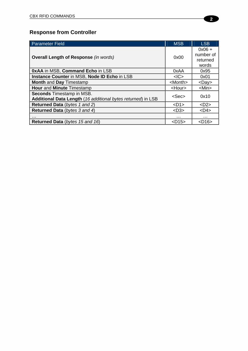
CBX RFID COMMANDS
2
Response from Controller Parameter Field MSB LSB
Overall Length of Response (in words) 0x00
0x06 + number of returned words
0xAA in MSB, Command Echo in LSB 0xAA 0x95 Instance Counter in MSB, Node ID Echo in LSB <IC> 0x01 Month and Day Timestamp <Month> <Day> Hour and Minute Timestamp <Hour> <Min> Seconds Timestamp in MSB. Additional Data Length (16 additional bytes returned) in LSB <Sec> 0x10
Returned Data (bytes 1 and 2) <D1> <D2> Returned Data (bytes 3 and 4) <D3> <D4> … … … Returned Data (bytes 15 and 16) <D15> <D16>

CBX PROTOCOL REFERENCE MANUAL
88
2
CBX COMMAND 0XA6: MULTI-TAG BLOCK WRITE BY ID Command 0xA6 - Description The Multi-Tag Block Write by ID Command is used to write a contiguous segment of data to a specific RFID tag identified by its tag ID. An error packet is sent if the specific tag is not present and the Timeout Value expires. When the Start Address is set to zero (0x0000), the controller will start writing at the beginning (or first accessible byte) of the tag. If the Block Size exceeds the last tag address, the controller will return an error message. Command 0xA6 - CBx Example This example instructs the controller at Node 01 to write 16 bytes of data to the tag containing the specified tag ID, beginning at tag address 0x0001. A Timeout Value of 3 seconds (0x0BB8 = 3000 x 1msec increments) is set for the completion of the command. Command from Host Parameter Field MSB LSB CBx Header in MSB, Node ID in LSB 0xFF 0x01
Overall Length of Command (in words) 0x00
0x0B + number of words in
Block Size 0xAA in MSB, Command ID in LSB 0xAA 0xA6 0x00 in MSB. Node ID in LSB 0x00 0x01 Timeout Value 0x0B 0xB8 Start Address 0x00 0x01 Block Size 0x00 0x10 AFI in MSB, 0x00 in LSB 0x00 0x00 Tag ID (bytes 1 and 2) <ID1> <ID2> Tag ID (bytes 3 and 4) <ID3> <ID4> Tag ID (bytes 5 and 6) <ID5> <ID6> Tag ID (bytes 7 and 8) <ID7> <ID8> Data (bytes 1 and 2) <D1> <D2> Data (bytes 3 and 4) <D3> <D4> … … … Data (bytes 15 and 16) <D15> <D16>

CBX RFID COMMANDS
2
Response from Controller Parameter Field MSB LSB Overall Length of Response (in words) 0x00 0x06 0xAA in MSB, Command Echo in LSB 0xAA 0xA6 Instance Counter in MSB. Node ID Echo in LSB <IC> 0x01 Month and Day Timestamp <Month> <Day> Hour and Minute Timestamp <Hour> <Min> Seconds Timestamp in MSB. 0x00 in LSB <Sec> 0x00

CBX PROTOCOL REFERENCE MANUAL
90
2
CBX COMMAND 0XC0: SET UHF CONTROLLER CONFIGURATION Command 0xC0 - Description The Set UHF Controller Configuration Command is used to modify and save changes to the UHF-Series controller’s configuration, which will be stored in the unit’s flash memory.
NOTE
It is recommended that the user first run the Command 0xC1: "Get UHF Controller Configuration" and make note of the current controller configuration values prior to executing this command.
Command 0xC0 - CBx Example This example permits the user to modify or write the indicated configuration parameters to the flash memory of the UHF controller at Node 01. The total number of bytes available for this purpose is nine. Command from Host Parameter Field MSB LSB CBx Header in MSB, Node ID in LSB 0xFF 0x01 Overall Length of Command (in words) 0x00 0x08 0xAA in MSB. Command ID in LSB: (0x43) 0xAA 0xC0 0x00 in MSB, Node ID in LSB 0x00 0x01 UHF Configuration Byte 1 in MSB UHF Configuration Byte 2 in LSB These two bytes represent the Reader Output Power (value from 0 to 500 mW).
<Byte 1> <Byte 2>
UHF Configuration Byte 3 in MSB UHF Configuration Byte 4 in LSB
<Reserved>* <Reserved>*
UHF Configuration Byte 5 in MSB UHF Configuration Byte 6 in LSB
<Reserved>* <Reserved>*
UHF Configuration Byte 7 in MSB UHF Configuration Byte 8 in LSB Byte 8 is partially reserved according to the table below. This byte permits the user to select the specific UHF Channel through which commands are transmitted. The user can write one of the following values: 0, 3, 6, or 9 in bits 4 to 7.
BIT Description 0 Reserved* 1 Reserved* 2 Reserved* 3 Reserved* 4 <Channel ID value> 5 <Channel ID value> 6 <Channel ID value> 7 <Channel ID value>
This parameter is ignored by BIS U-62_-xxx-111_ US models.
<Reserved>* <Partially Reserved>

CBX RFID COMMANDS
2
Parameter Field MSB LSB UHF Configuration Byte 9 in MSB 0x00 in LSB Byte 9 is partially reserved according to the table below. This byte permits the user to enable/disable the Choose Nearest One property. If the Choose Nearest One property is disabled (bit = 0), an error response is generated whenever a single-tag read/write command is executed in a multi-tag environment. If the Choose Nearest One property is enabled (bit = 1), the read/write command is executed on the tag with the strongest signal.
BIT Description 0 Reserved* 1 <Choose Nearest One> 2 Reserved* 3 Reserved* 4 Reserved* 5 Reserved* 6 Reserved* 7 Reserved*
<Partially Reserved>
0x00
NOTE
* Leave the default value retrieved through the 0xC1 "Get UHF Controller Configuration" command.
Response from Controller Parameter Field MSB LSB Overall Length of Response (in words) 0x00 0x06 0xAA in MSB. Command Echo in LSB 0xAA 0xC0 Instance Counter in MSB, Node ID Echo in LSB <IC> 0x01 Month and Day Timestamp: (March 19th) 0x03 0x13 Hour and Minute Timestamp: (10:11: AM) 0x0A 0x0B Seconds Timestamp in MSB: (36 seconds) 0x00 in LSB 0x24 0x00

CBX PROTOCOL REFERENCE MANUAL
92
2
CBX COMMAND 0XC1: GET UHF CONTROLLER CONFIGURATION Command 0xC1 - Description The Get UHF Controller Configuration Command is used to retrieve the configuration settings stored in the UHF-Series controller’s flash memory. These are the same values that are set with the Set UHF Controller Configuration Command. Command 0xC1 - CBx Example This example retrieves the stored configuration settings from the flash memory of the UHF controller at Node 01. Command from Host Parameter Field MSB LSB CBx Header in MSB, Node ID in LSB 0xFF 0x01 Overall Length of Command (in words) 0x00 0x06 0xAA in MSB. Command ID in LSB: (0x33) 0xAA 0xC1 0x00 in MSB. Node ID in LSB 0x00 0x01 Not Used (default: 0x00, 0x00) 0x00 0x00 Not Used (default: 0x00, 0x00) 0x00 0x00 Not Used (default: 0x00, 0x00) 0x00 0x00
Response from Controller Parameter Field MSB LSB Overall Length of Response (in words) 0x00 0x0B 0xAA in MSB. Command Echo in LSB 0xAA 0xC1 Instance Counter in MSB. Node ID Echo in LSB <IC> 0x01 Month and Day Timestamp: (March 19th) 0x03 0x13 Hour and Minute Timestamp: (10:11: AM) 0x0A 0x0B Seconds Timestamp in MSB (:36 seconds) Additional Data Length in LSB (in bytes 0x0A)
0x24 0x0A
UHF Configuration Byte 1 in MSB UHF Configuration Byte 2 in LSB These two bytes represent the Reader Output Power (value from 0 to 500 mW).
<Byte 1> <Byte 2>
UHF Configuration Byte 3 in MSB UHF Configuration Byte 4 in LSB
<Byte 3> <Byte 4>
UHF Configuration Byte 5 in MSB UHF Configuration Byte 6 in LSB
<Byte 5> <Byte 6>
UHF Configuration Byte 7 in MSB UHF Configuration Byte 8 in LSB
<Byte 7> <Byte 8>
UHF Configuration Byte 9 in MSB 0x00 in LSB
<Byte 9> 0x00

CBX RFID COMMANDS
2
CBX COMMAND 0XC2: READ EPC CODE Command 0xC2 - Description The Read EPC Code Command instructs the controller to retrieve the EPC memory area of a single UHF Class 1 Gen 2 RFID tag memory. Command 0xC2 - CBx Example This example instructs the controller at Node 01 to read the EPC memory from a tag. A Timeout Value of 2 seconds (0x07D0 = 2000 x one-millisecond increments) is set for the completion of the command. Command from Host Parameter Field MSB LSB CBx Header in MSB, Node ID in LSB 0xFF 0x01 Overall Length of Command (in words) 0x00 0x06 0xAA in MSB. Command ID in LSB (0xC2) 0xAA 0xC2 0x00 in MSB. Node ID in LSB 0x00 0x01 Timeout Value 0x07 0xD0 Not Used (0x00, 0x00) 0x00 0x00 Not Used (0x00, 0x00) 0x00 0x00
Response from Controller (Tag Found) Parameter Field MSB LSB Overall Length of Response (in words) 0x00 0x0C 0xAA in MSB. Command Echo in LSB 0xAA 0xC2 Instance Counter in MSB. Node ID Echo in LSB <IC> 0x01 Month and Day Timestamp:(March 19th) 0x03 0x13 Hour and Minute Timestamp: (10:11: AM) 0x0A 0x0B Seconds Timestamp in MSB: (:36 seconds). Additional Data Length in LSB: (in bytes 0x0C)
0x24 0x0C
EPC (bytes 1 and 2) 0xE0 0x04 EPC (bytes 3 and 4) 0x01 0x00 EPC (bytes 5 and 6) 0x00 0x2E EPC (bytes 7 and 8) 0xEB 0x34 EPC (bytes 9 and 10) 0x11 0x35 EPC (bytes 11 and 12) 0x16 0xAD
See par. EPC Class 1 Gen 2 Tag Memory Structure in Appendix for details.
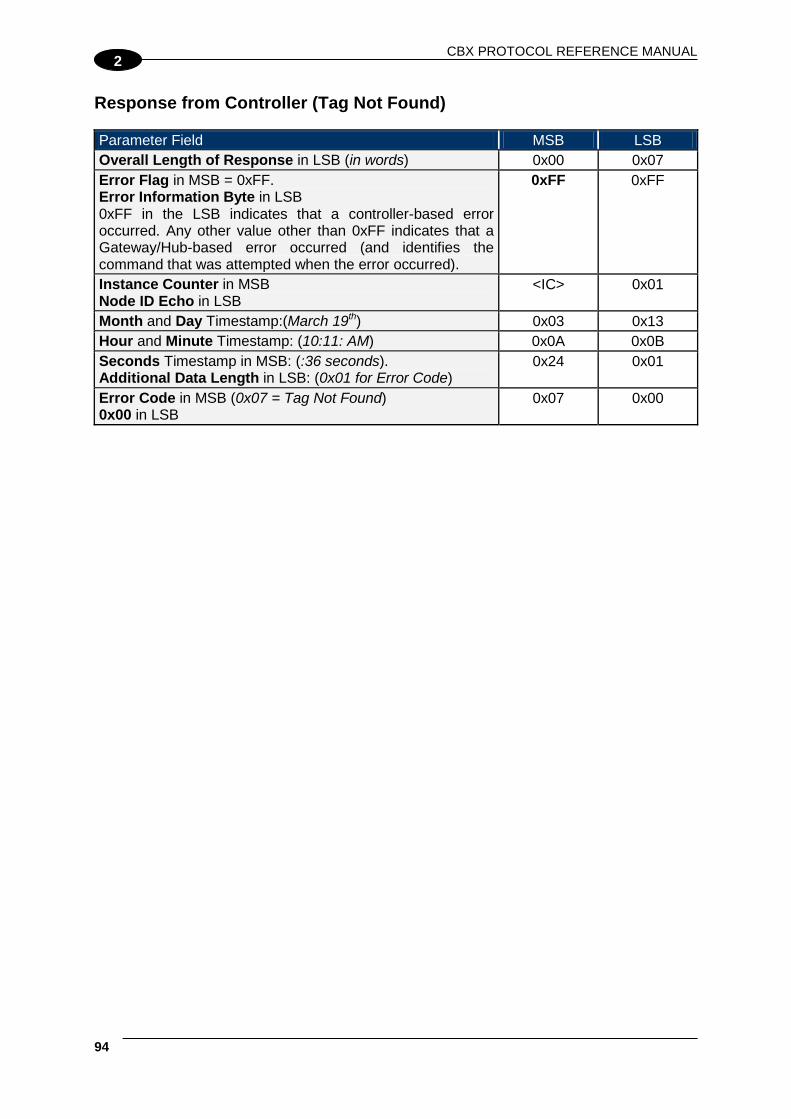
CBX PROTOCOL REFERENCE MANUAL
94
2
Response from Controller (Tag Not Found) Parameter Field MSB LSB Overall Length of Response in LSB (in words) 0x00 0x07 Error Flag in MSB = 0xFF. Error Information Byte in LSB 0xFF in the LSB indicates that a controller-based error occurred. Any other value other than 0xFF indicates that a Gateway/Hub-based error occurred (and identifies the command that was attempted when the error occurred).
0xFF 0xFF
Instance Counter in MSB Node ID Echo in LSB
<IC> 0x01
Month and Day Timestamp:(March 19th) 0x03 0x13 Hour and Minute Timestamp: (10:11: AM) 0x0A 0x0B Seconds Timestamp in MSB: (:36 seconds). Additional Data Length in LSB: (0x01 for Error Code)
0x24 0x01
Error Code in MSB (0x07 = Tag Not Found) 0x00 in LSB
0x07 0x00

CBX RFID COMMANDS
2
CBX COMMAND 0XC3: WRITE EPC CODE Command 0xC3 - Description The Write EPC Code Command instructs the controller to write the EPC memory area of a single UHF Class 1 Gen 2 RFID tag memory. Command 0xC3 - CBx Example This example instructs the controller at Node 01 to write the specified bytes in the EPC memory of a tag. A Timeout Value of 2 seconds (0x07D0 = 2000 x one-millisecond increments) is set for the completion of this command. Command from Host Parameter Field MSB LSB CBx Header in MSB, Node ID in LSB 0xFF 0x01 Overall Length of Command (in words) 0x00 0x0A 0xAA in MSB. Command ID in LSB (0xC3) 0xAA 0xC3 0x00 in MSB. Node ID in LSB 0x00 0x01 Timeout Value (measured in ms) 0x07 0xD0 EPC Write Data (bytes 1 and 2) 0x48 0x45 EPC Write Data (bytes 3 and 4) 0x4C 0x4C EPC Write Data (bytes 5 and 6) 0x58 0x45 EPC Write Data (bytes 7 and 8) 0xAB 0x6F EPC Write Data (byte 9 and 10) 0x4E 0x45 EPC Write Data (byte 11 and 12) 0x4F 0x00
Response from Controller Parameter Field MSB LSB Overall Length of Response (in words) 0x00 0x06 0xAA in MSB. Command Echo in LSB 0xAA 0xC3 Instance Counter in MSB. Node ID Echo in LSB <IC> 0x01 Month and Day Timestamp: (March 19th) 0x03 0x13 Hour and Minute Timestamp: (10:11: AM) 0x0A 0x0B Seconds Timestamp in MSB (:36 seconds). 0x00 in LSB 0x24 0x00
See par. EPC Class 1 Gen 2 Tag Memory Structure in Appendix for details.
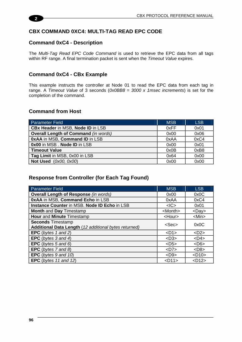
CBX PROTOCOL REFERENCE MANUAL
96
2
CBX COMMAND 0XC4: MULTI-TAG READ EPC CODE Command 0xC4 - Description The Multi-Tag Read EPC Code Command is used to retrieve the EPC data from all tags within RF range. A final termination packet is sent when the Timeout Value expires. Command 0xC4 - CBx Example This example instructs the controller at Node 01 to read the EPC data from each tag in range. A Timeout Value of 3 seconds (0x0BB8 = 3000 x 1msec increments) is set for the completion of the command. Command from Host Parameter Field MSB LSB CBx Header in MSB, Node ID in LSB 0xFF 0x01 Overall Length of Command (in words) 0x00 0x06 0xAA in MSB, Command ID in LSB 0xAA 0xC4 0x00 in MSB . Node ID in LSB 0x00 0x01 Timeout Value 0x0B 0xB8 Tag Limit in MSB, 0x00 in LSB 0x64 0x00 Not Used (0x00, 0x00) 0x00 0x00
Response from Controller (for Each Tag Found) Parameter Field MSB LSB Overall Length of Response (in words) 0x00 0x0C 0xAA in MSB, Command Echo in LSB 0xAA 0xC4 Instance Counter in MSB. Node ID Echo in LSB <IC> 0x01 Month and Day Timestamp <Month> <Day> Hour and Minute Timestamp <Hour> <Min> Seconds Timestamp Additional Data Length (12 additional bytes returned) <Sec> 0x0C
EPC (bytes 1 and 2) <D1> <D2> EPC (bytes 3 and 4) <D3> <D4> EPC (bytes 5 and 6) <D5> <D6> EPC (bytes 7 and 8) <D7> <D8> EPC (bytes 9 and 10) <D9> <D10> EPC (bytes 11 and 12) <D11> <D12>

CBX RFID COMMANDS
2
Final Response Packet Parameter Field MSB LSB Overall Length of Response (in words) 0x00 0x07 0xAA in MSB, 0xFF in LSB 0xAA 0xFF Instance Counter in MSB. Node ID Echo in LSB <IC> 0x01 Month and Day Timestamp <Month> <Day> Hour and Minute Timestamp <Hour> <Min> Seconds Timestamp Additional Data Length (2 bytes: “Number of Tags” and “Status”)
<Sec> 0x02
Number of Tags Found in MSB Status in LSB. 0x00 = operation completed successfully, 0x07 = Read Tag ID failed / Tag Not Found.
<# of tags found>
<0x00
See par. EPC Class 1 Gen 2 Tag Memory Structure in Appendix for details.

CBX PROTOCOL REFERENCE MANUAL
98
A
A REFERENCES EPC CLASS 1 GEN 2 TAG MEMORY STRUCTURE The memory in Balluff’s EPC Class 1 Gen 2 tag UHF-G2-525xx is organized in three areas: Name Description Size EPC EPC memory according to the EPCglobal Standard 96-bit (12 bytes) TID Read Only Unique identifier 64-bits (8 bytes) USER User memory 512-bit (64 bytes)
EPC EPC is a numbering scheme that allows assignment of a unique identifier to any physical object. It can be regarded as the next generation of Universal Product Code (UPC), which is used on most products today. EPC enables the means to assign a unique identifier to each item, thus allowing every item to be uniquely identified. To have more details on the structure of the EPC memory area please consult:
• EPC Radio-Frequency Identity Protocols Class-1 Generation-2 UHF RFID Protocol for Communications at 860 Mhz – 960 Mhz, Version 1.1.0 (December 17, 2005)
In our UHF-G2-525xx tag this memory area is pre-programmed with the TID unique identifier and padded with zeroes. The user can change that but it’s important to note that only tags with different EPC codes will be discriminated in a multi-tag reading environment. TID This is a read-only area that holds a unique tag identifier number. This area can be accessed using the common CBx Read ID commands. USER This is the normal data area that can be accessed using the common CBx Read and Write commands.
NOTE
The fastest access memory is the EPC area. For applications where speed is important the use of this memory is recommended.
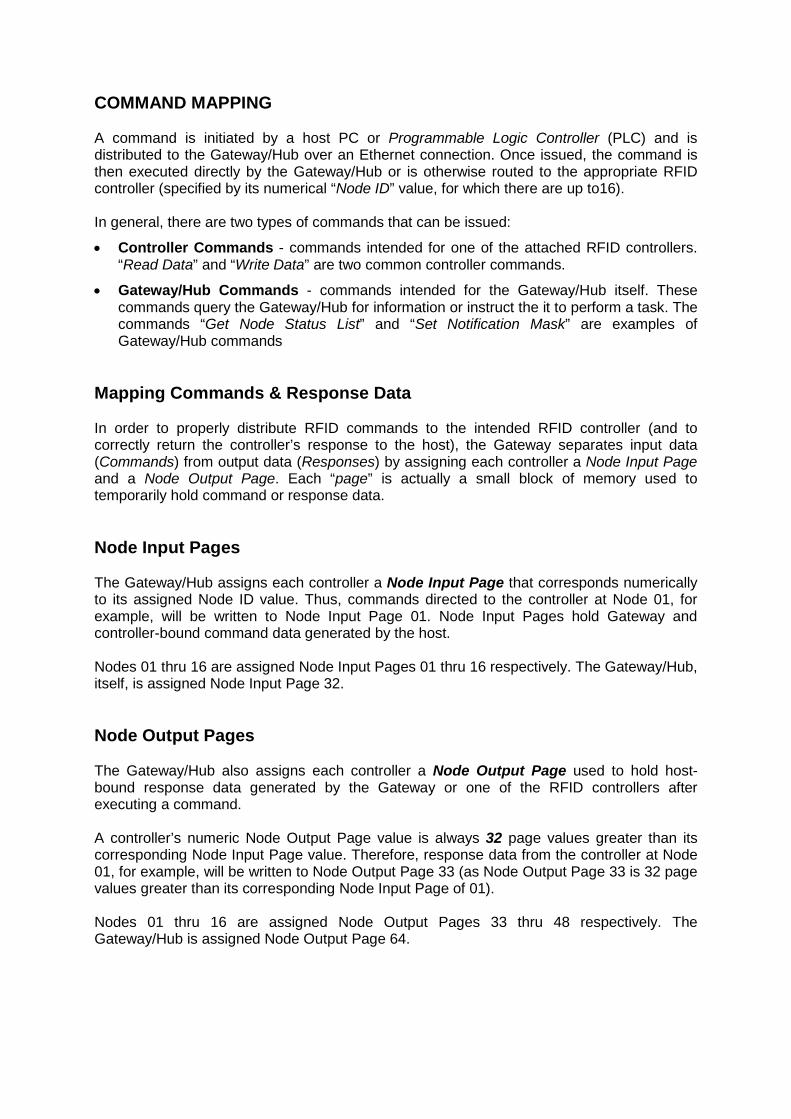
COMMAND MAPPING A command is initiated by a host PC or Programmable Logic Controller (PLC) and is distributed to the Gateway/Hub over an Ethernet connection. Once issued, the command is then executed directly by the Gateway/Hub or is otherwise routed to the appropriate RFID controller (specified by its numerical “Node ID” value, for which there are up to16). In general, there are two types of commands that can be issued:
• Controller Commands - commands intended for one of the attached RFID controllers. “Read Data” and “Write Data” are two common controller commands.
• Gateway/Hub Commands - commands intended for the Gateway/Hub itself. These commands query the Gateway/Hub for information or instruct the it to perform a task. The commands “Get Node Status List” and “Set Notification Mask” are examples of Gateway/Hub commands
Mapping Commands & Response Data In order to properly distribute RFID commands to the intended RFID controller (and to correctly return the controller’s response to the host), the Gateway separates input data (Commands) from output data (Responses) by assigning each controller a Node Input Page and a Node Output Page. Each “page” is actually a small block of memory used to temporarily hold command or response data. Node Input Pages The Gateway/Hub assigns each controller a Node Input Page that corresponds numerically to its assigned Node ID value. Thus, commands directed to the controller at Node 01, for example, will be written to Node Input Page 01. Node Input Pages hold Gateway and controller-bound command data generated by the host. Nodes 01 thru 16 are assigned Node Input Pages 01 thru 16 respectively. The Gateway/Hub, itself, is assigned Node Input Page 32. Node Output Pages The Gateway/Hub also assigns each controller a Node Output Page used to hold host-bound response data generated by the Gateway or one of the RFID controllers after executing a command. A controller’s numeric Node Output Page value is always 32 page values greater than its corresponding Node Input Page value. Therefore, response data from the controller at Node 01, for example, will be written to Node Output Page 33 (as Node Output Page 33 is 32 page values greater than its corresponding Node Input Page of 01). Nodes 01 thru 16 are assigned Node Output Pages 33 thru 48 respectively. The Gateway/Hub is assigned Node Output Page 64.
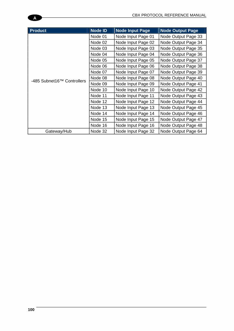
CBX PROTOCOL REFERENCE MANUAL
100
A
Product Node ID Node Input Page Node Output Page
-485 Subnet16™ Controllers
Node 01 Node Input Page 01 Node Output Page 33 Node 02 Node Input Page 02 Node Output Page 34 Node 03 Node Input Page 03 Node Output Page 35 Node 04 Node Input Page 04 Node Output Page 36 Node 05 Node Input Page 05 Node Output Page 37 Node 06 Node Input Page 06 Node Output Page 38 Node 07 Node Input Page 07 Node Output Page 39 Node 08 Node Input Page 08 Node Output Page 40 Node 09 Node Input Page 09 Node Output Page 41 Node 10 Node Input Page 10 Node Output Page 42 Node 11 Node Input Page 11 Node Output Page 43 Node 12 Node Input Page 12 Node Output Page 44 Node 13 Node Input Page 13 Node Output Page 45 Node 14 Node Input Page 14 Node Output Page 46 Node 15 Node Input Page 15 Node Output Page 47 Node 16 Node Input Page 16 Node Output Page 48
Gateway/Hub Node 32 Node Input Page 32 Node Output Page 64

N
r. 89
8326
E . E
ditio
n 13
08; S
ubje
ct to
mod
ifica
tion.