CAN-CBX-REL4 · Fig. 1: Block circuit diagram of the CAN-CBX-REL4 module The CAN-CBX-REL4 module...
83
CAN-CBX-REL4 Manual • Doc.-No.: C.3012.21 / Rev. 1.0 Page 1 of 83 esd electronic system design gmbh Vahrenwalder Str. 207 • 30165 Hannover • Germany www.esd-electronics.com • Fax: 0511/37 29 8-68 Phone: 0511/37 29 80 • International: +49-5 11-37 29 80 CAN-CBX-REL4 CANopen Module with 4 Relay Outputs with InRailBus Manual to Product C.3012.02
Transcript of CAN-CBX-REL4 · Fig. 1: Block circuit diagram of the CAN-CBX-REL4 module The CAN-CBX-REL4 module...
CAN-CBX-REL4 Manual • Doc.-No.: C.3012.21 / Rev. 1.0 Page 1 of 83
esd electronic system design gmbhVahrenwalder Str. 207 • 30165 Hannover • Germany
www.esd-electronics.com • Fax: 0511/37 29 8-68 Phone: 0511/37 29 80 • International: +49-5 11-37 29 80
CAN-CBX-REL4CANopen Module with 4 Relay Outputs
with InRailBus
Manual
to Product C.3012.02
Manual • Doc.-No.: C.3012.21 / Rev. 1.0 CAN-CBX-REL4 Page 2 of 83
N O T E
The information in this document has been carefully checked and is believed to be entirely reliable. esdmakes no warranty of any kind with regard to the material in this document, and assumes noresponsibility for any errors that may appear in this document. esd reserves the right to make changeswithout notice to this, or any of its products, to improve reliability, performance or design.
esd assumes no responsibility for the use of any circuitry other than circuitry which is part of a productof esd gmbh.
esd does not convey to the purchaser of the product described herein any license under the patent rightsof esd gmbh nor the rights of others.
esd electronic system design gmbhVahrenwalder Str. 20730165 HannoverGermany
Phone: +49-511-372 98-0Fax: +49-511-372 98-68E-mail: [email protected]: www.esd-electronics.com
USA / Canada:esd electronics Inc.525 Bernardston RoadSuite 1Greenfield, MA 01301 USA
Phone: +1-800-732-8006Fax: +1-800-732-8093E-mail: [email protected]: www.esd-electronics.us
CAN-CBX-REL4 Manual • Doc.-No.: C.3012.21 / Rev. 1.0 Page 3 of 83
Document-File: I:\texte\Doku\MANUALS\CAN\CBX\REL4\English\CBX-REL4_10.en9
Date of print: 2007-10-17
PCB version: Rev.1.1
Firmware version: 2.0
Changes in the chapters
The changes in the document listed below affect changes in the hardware and firmware as well aschanges in the description of facts only.
Chapter Changes versus previous version
- First English version
Technical details are subject to change without further notice.

Manual • Doc.-No.: C.3012.21 / Rev. 1.0 CAN-CBX-REL4 Page 4 of 83
This page is intentionally left blank.
Contents Page
CAN-CBX-REL4 Manual • Doc.-No.: C.3012.21 / Rev. 1.0 Page 5 of 83
1. Overview . . . . . . . . . . . . . . . . . . . . . . . . . . . . . . . . . . . . . . . . . . . . . . . . . . . . . . . . . . . . . . . . . 7
2. Technical Data . . . . . . . . . . . . . . . . . . . . . . . . . . . . . . . . . . . . . . . . . . . . . . . . . . . . . . . . . . . . . 82.1 General Technical Data . . . . . . . . . . . . . . . . . . . . . . . . . . . . . . . . . . . . . . . . . . . . . . . . 82.2 CPU-Unit . . . . . . . . . . . . . . . . . . . . . . . . . . . . . . . . . . . . . . . . . . . . . . . . . . . . . . . . . . . 82.3 CAN-Interface . . . . . . . . . . . . . . . . . . . . . . . . . . . . . . . . . . . . . . . . . . . . . . . . . . . . . . . 92.4 Relay-Connection . . . . . . . . . . . . . . . . . . . . . . . . . . . . . . . . . . . . . . . . . . . . . . . . . . . . . 9
3. Hardware Installation . . . . . . . . . . . . . . . . . . . . . . . . . . . . . . . . . . . . . . . . . . . . . . . . . . . . . . 113.1 Connecting Diagram . . . . . . . . . . . . . . . . . . . . . . . . . . . . . . . . . . . . . . . . . . . . . . . . . . 113.2 LEDs . . . . . . . . . . . . . . . . . . . . . . . . . . . . . . . . . . . . . . . . . . . . . . . . . . . . . . . . . . . . . 12
3.2.1 Relay LEDs 1-4 . . . . . . . . . . . . . . . . . . . . . . . . . . . . . . . . . . . . . . . . . . . . . . 123.2.2 Indicator States of the Status-LEDs . . . . . . . . . . . . . . . . . . . . . . . . . . . . . . . 13
3.3 Coding Switches . . . . . . . . . . . . . . . . . . . . . . . . . . . . . . . . . . . . . . . . . . . . . . . . . . . . 163.3.1 Setting the Node-ID via Coding Switch . . . . . . . . . . . . . . . . . . . . . . . . . . . . 163.3.2 Setting the Baud Rate . . . . . . . . . . . . . . . . . . . . . . . . . . . . . . . . . . . . . . . . . 17
3.4 Installation of the Module Using Optional InRailBus Connector . . . . . . . . . . . . . . . . . 183.4.1 Connecting Power Supply and CAN-Signals to CBX-InRailBus . . . . . . . . . . 203.4.2 Connection of the Power Supply Voltage . . . . . . . . . . . . . . . . . . . . . . . . . . . 203.4.3 Connection of CAN . . . . . . . . . . . . . . . . . . . . . . . . . . . . . . . . . . . . . . . . . . . 21
3.5 Remove the CAN-CBX Module from the Optional InRailBus . . . . . . . . . . . . . . . . . . 21
4. Description of the Units . . . . . . . . . . . . . . . . . . . . . . . . . . . . . . . . . . . . . . . . . . . . . . . . . . . . . 224.1 CAN Interface . . . . . . . . . . . . . . . . . . . . . . . . . . . . . . . . . . . . . . . . . . . . . . . . . . . . . . 22
5. Connector Pin Assignment . . . . . . . . . . . . . . . . . . . . . . . . . . . . . . . . . . . . . . . . . . . . . . . . . . 235.1 Power Supply Voltage X100 . . . . . . . . . . . . . . . . . . . . . . . . . . . . . . . . . . . . . . . . . . . 235.2 CAN-Bus X600 . . . . . . . . . . . . . . . . . . . . . . . . . . . . . . . . . . . . . . . . . . . . . . . . . . . . . 245.3 CAN and Power Supply Voltage via InRailBus Connector X101 . . . . . . . . . . . . . . . . 255.4 Relay Outputs X300 . . . . . . . . . . . . . . . . . . . . . . . . . . . . . . . . . . . . . . . . . . . . . . . . . . 26
6. Correctly Wiring Electrically Isolated CAN Networks . . . . . . . . . . . . . . . . . . . . . . . . . . . . 27
7. CAN-Bus Troubleshooting Guide . . . . . . . . . . . . . . . . . . . . . . . . . . . . . . . . . . . . . . . . . . . . . 317.1 Termination . . . . . . . . . . . . . . . . . . . . . . . . . . . . . . . . . . . . . . . . . . . . . . . . . . . . . . . . 317.2 CAN_H/CAN_L Voltage . . . . . . . . . . . . . . . . . . . . . . . . . . . . . . . . . . . . . . . . . . . . . 327.3 Ground . . . . . . . . . . . . . . . . . . . . . . . . . . . . . . . . . . . . . . . . . . . . . . . . . . . . . . . . . . . 327.4 CAN Transceiver Resistance Test . . . . . . . . . . . . . . . . . . . . . . . . . . . . . . . . . . . . . . . 33
8. Software . . . . . . . . . . . . . . . . . . . . . . . . . . . . . . . . . . . . . . . . . . . . . . . . . . . . . . . . . . . . . . . . 348.1 Definition of Terms . . . . . . . . . . . . . . . . . . . . . . . . . . . . . . . . . . . . . . . . . . . . . . . . . . 348.2 NMT-Boot-up . . . . . . . . . . . . . . . . . . . . . . . . . . . . . . . . . . . . . . . . . . . . . . . . . . . . . . 358.3 CANopen Object Directory . . . . . . . . . . . . . . . . . . . . . . . . . . . . . . . . . . . . . . . . . . . . 35
8.3.1 Access on the Object Directory via SDOs . . . . . . . . . . . . . . . . . . . . . . . . . . 358.4 Overview of used CANopen Identifiers . . . . . . . . . . . . . . . . . . . . . . . . . . . . . . . . . . . 39
8.4.1 Setting the COB-ID . . . . . . . . . . . . . . . . . . . . . . . . . . . . . . . . . . . . . . . . . . . 398.5 Default PDO Assignment . . . . . . . . . . . . . . . . . . . . . . . . . . . . . . . . . . . . . . . . . . . . . . 40
Contents Page
Manual • Doc.-No.: C.3012.21 / Rev. 1.0 CAN-CBX-REL4 Page 6 of 83
8.6 Setting the Relays . . . . . . . . . . . . . . . . . . . . . . . . . . . . . . . . . . . . . . . . . . . . . . . . . . . . 418.6.1 Supported Transmission Types Based on DS-301 . . . . . . . . . . . . . . . . . . . . 41
8.7 Implemented CANopen-Objects . . . . . . . . . . . . . . . . . . . . . . . . . . . . . . . . . . . . . . . . . 428.7.1 Device Type (1000h) . . . . . . . . . . . . . . . . . . . . . . . . . . . . . . . . . . . . . . . . . . 448.7.2 Error Register (1001h) . . . . . . . . . . . . . . . . . . . . . . . . . . . . . . . . . . . . . . . . . 458.7.3 Manufacturer Status Register (1002h) . . . . . . . . . . . . . . . . . . . . . . . . . . . . . 468.7.4 Pre-defined Error Field (1003h) . . . . . . . . . . . . . . . . . . . . . . . . . . . . . . . . . . 478.7.5 COB-ID SYNC Message (1005h) . . . . . . . . . . . . . . . . . . . . . . . . . . . . . . . . 498.7.6 Manufacturer’s Device Name (1008h) . . . . . . . . . . . . . . . . . . . . . . . . . . . . . 508.7.7 Manufacturer’s Hardware Version (1009h) . . . . . . . . . . . . . . . . . . . . . . . . . . 518.7.8 Manufacturer’s Software Version (100Ah) . . . . . . . . . . . . . . . . . . . . . . . . . . 518.7.9 Guard Time (100Ch) und Life Time Factor (100Dh) . . . . . . . . . . . . . . . . . . . 528.7.10 Node Guarding Identifier (100Eh) . . . . . . . . . . . . . . . . . . . . . . . . . . . . . . . 538.7.11 Store Parameters (1010h) . . . . . . . . . . . . . . . . . . . . . . . . . . . . . . . . . . . . . . 548.7.12 Restore Default Parameters (1011h) . . . . . . . . . . . . . . . . . . . . . . . . . . . . . . 558.7.13 COB_ID Emergency Object (1014h) . . . . . . . . . . . . . . . . . . . . . . . . . . . . . 568.7.14 Inhibit Time EMCY (1015h) . . . . . . . . . . . . . . . . . . . . . . . . . . . . . . . . . . . . 578.7.15 Consumer Heartbeat Time (1016h) . . . . . . . . . . . . . . . . . . . . . . . . . . . . . . . 588.7.16 Producer Heartbeat Time (1017h) . . . . . . . . . . . . . . . . . . . . . . . . . . . . . . . 598.7.17 Identity Object (1018h) . . . . . . . . . . . . . . . . . . . . . . . . . . . . . . . . . . . . . . . 608.7.18 Verify Configuration (1020h) . . . . . . . . . . . . . . . . . . . . . . . . . . . . . . . . . . . 628.7.19 Error Behaviour Object (1029h) . . . . . . . . . . . . . . . . . . . . . . . . . . . . . . . . . 638.7.20 Receive PDO Communication Parameter 1400h - 1403h . . . . . . . . . . . . . . . 648.7.21 Receive PDO Mapping Parameter 1600h - 1603h . . . . . . . . . . . . . . . . . . . . 65
8.8 Device Profile Area . . . . . . . . . . . . . . . . . . . . . . . . . . . . . . . . . . . . . . . . . . . . . . . . . . 708.8.1 Overview of implemented Objects 6200h ... 6270h . . . . . . . . . . . . . . . . . . . . 708.8.2 Write Output 8-Bit (6200h) . . . . . . . . . . . . . . . . . . . . . . . . . . . . . . . . . . . . . 718.8.3 Change Polarity Output 8-bit (6202h) . . . . . . . . . . . . . . . . . . . . . . . . . . . . . . 728.8.4 Error Mode Output 8-bit (6206h) . . . . . . . . . . . . . . . . . . . . . . . . . . . . . . . . . 738.8.5 Error Value Output 8-bit (6207h) . . . . . . . . . . . . . . . . . . . . . . . . . . . . . . . . . 748.8.6 Filter Mask Output 8-bit (6208h) . . . . . . . . . . . . . . . . . . . . . . . . . . . . . . . . . 758.8.7 Write Output Bit 1 to 4 (6220h) . . . . . . . . . . . . . . . . . . . . . . . . . . . . . . . . . . 768.8.8 Change Polarity Bit 1 to 4 (6240h) . . . . . . . . . . . . . . . . . . . . . . . . . . . . . . . . 778.8.9 Error Mode Output Bit 1 to 4 (6250h) . . . . . . . . . . . . . . . . . . . . . . . . . . . . . 788.8.10 Error Value Output Bit 1 to 4 (6260h) . . . . . . . . . . . . . . . . . . . . . . . . . . . . 798.8.11 Filter Mask Output Bit 1 to 4 (6270h) . . . . . . . . . . . . . . . . . . . . . . . . . . . . 80
8.9 Manufacturer Specific Profile Area . . . . . . . . . . . . . . . . . . . . . . . . . . . . . . . . . . . . . . . 818.10 Firmware-Update via DS-302-Objects (1F51h-1F52h) . . . . . . . . . . . . . . . . . . . . . . . . 82
8.10.1 Download Control via Object 1F51h . . . . . . . . . . . . . . . . . . . . . . . . . . . . . . 83
iOverview
CAN-CBX-REL4 Manual • Doc.-No.: C.3012.21 / Rev. 1.0 Page 7 of 83
+5 V=
+5 V=
CANBUS
CAN
CAN Baud Rate
CANopen Node-ID
LEDs
PhysicalCANLayer
DigitalIsolator
MicrocontrollerMB90497
Electrical Isolation Coding Switches
Power Supply24 V(DC)
ME-MAXBus Connector
Power ConnectorMSTBO 2,5/4-
G1L-KMGY
CAN ConnectorMC1,5/5-GF-3,81
DC/DCConverter
X30
0 C
onne
ctor
plu
g
2 change over contacts2 normally open contacts
1. Overview
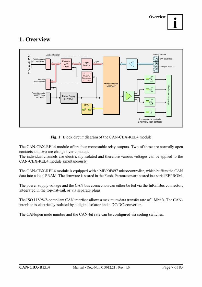
Fig. 1: Block circuit diagram of the CAN-CBX-REL4 module
The CAN-CBX-REL4 module offers four monostable relay outputs. Two of these are normally opencontacts and two are change over contacts.The individual channels are electrically isolated and therefore various voltages can be applied to theCAN-CBX-REL4 module simultaneously.
The CAN-CBX-REL4 module is equipped with a MB90F497 microcontroller, which buffers the CANdata into a local SRAM. The firmware is stored in the Flash. Parameters are stored in a serial EEPROM.
The power supply voltage and the CAN bus connection can either be fed via the InRailBus connector,integrated in the top-hat-rail, or via separate plugs.
The ISO 11898-2-compliant CAN interface allows a maximum data transfer rate of 1 Mbit/s. The CAN-interface is electrically isolated by a digital isolator and a DC/DC-converter.
The CANopen node number and the CAN-bit rate can be configured via coding switches.
Technical Data
Manual • Doc.-No.: C.3012.21 / Rev. 1.0 CAN-CBX-REL4 Page 8 of 83
2. Technical Data
2.1 General Technical Data
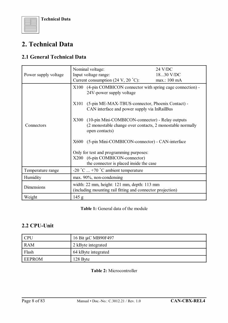
Power supply voltageNominal voltage: 24 V/DCInput voltage range: 18...30 V/DCCurrent consumption (24 V, 20 C): max.: 100 mA
Connectors
X100 (4-pin COMBICON connector with spring cage connection) -24V-power supply voltage
X101 (5-pin ME-MAX-TBUS-connector, Phoenix Contact) - CAN interface and power supply via InRailBus
X300 (10-pin Mini-COMBICON-connector) - Relay outputs (2 monostable change over contacts, 2 monostable normallyopen contacts)
X600 (5-pin Mini-COMBICON-connector) - CAN-interface
Only for test and programming purposes:X200 (6-pin COMBICON-connector)
the connector is placed inside the caseTemperature range -20 C ... +70 C ambient temperatureHumidity max. 90%, non-condensing
Dimensions width: 22 mm, height: 121 mm, depth: 113 mm (including mounting rail fitting and connector projection)
Weight 145 g
Table 1: General data of the module
2.2 CPU-Unit
CPU 16 Bit C MB90F497RAM 2 kByte integratedFlash 64 kByte integrated EEPROM 128 Byte
Table 2: Microcontroller
Technical Data
CAN-CBX-REL4 Manual • Doc.-No.: C.3012.21 / Rev. 1.0 Page 9 of 83
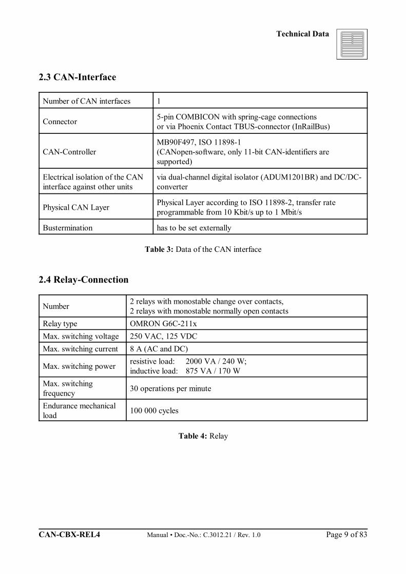
2.3 CAN-Interface
Number of CAN interfaces 1
Connector 5-pin COMBICON with spring-cage connections or via Phoenix Contact TBUS-connector (InRailBus)
CAN-ControllerMB90F497, ISO 11898-1(CANopen-software, only 11-bit CAN-identifiers aresupported)
Electrical isolation of the CANinterface against other units
via dual-channel digital isolator (ADUM1201BR) and DC/DC-converter
Physical CAN Layer Physical Layer according to ISO 11898-2, transfer rateprogrammable from 10 Kbit/s up to 1 Mbit/s
Bustermination has to be set externally
Table 3: Data of the CAN interface
2.4 Relay-Connection
Number 2 relays with monostable change over contacts,2 relays with monostable normally open contacts
Relay type OMRON G6C-211xMax. switching voltage 250 VAC, 125 VDC Max. switching current 8 A (AC and DC)
Max. switching power resistive load: 2000 VA / 240 W;inductive load: 875 VA / 170 W
Max. switchingfrequency 30 operations per minute
Endurance mechanicalload 100 000 cycles
Table 4: Relay
Technical Data
Manual • Doc.-No.: C.3012.21 / Rev. 1.0 CAN-CBX-REL4 Page 10 of 83
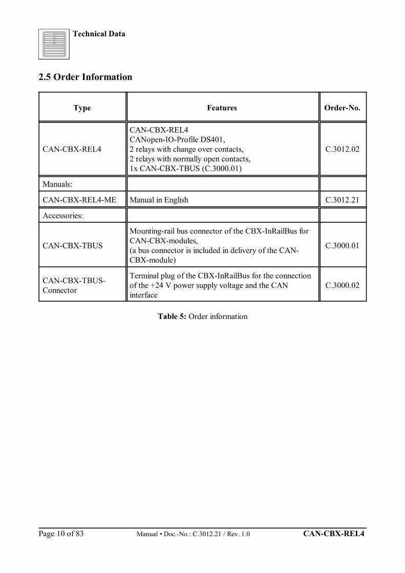
2.5 Order Information
Type Features Order-No.
CAN-CBX-REL4
CAN-CBX-REL4CANopen-IO-Profile DS401,2 relays with change over contacts,2 relays with normally open contacts,1x CAN-CBX-TBUS (C.3000.01)
C.3012.02
Manuals:
CAN-CBX-REL4-ME Manual in English C.3012.21
Accessories:
CAN-CBX-TBUS
Mounting-rail bus connector of the CBX-InRailBus forCAN-CBX-modules,(a bus connector is included in delivery of the CAN-CBX-module)
C.3000.01
CAN-CBX-TBUS-Connector
Terminal plug of the CBX-InRailBus for the connectionof the +24 V power supply voltage and the CANinterface
C.3000.02
Table 5: Order information

Hardware Installation
CAN-CBX-REL4 Manual • Doc.-No.: C.3012.21 / Rev. 1.0 Page 11 of 83
3. Hardware Installation
3.1 Connecting Diagram
Fig. 2: Connections of the CAN-CBX-REL4 module
The signal pin assignment can be found on page 23 and the following.
Hardware Installation
Manual • Doc.-No.: C.3012.21 / Rev. 1.0 CAN-CBX-REL4 Page 12 of 83
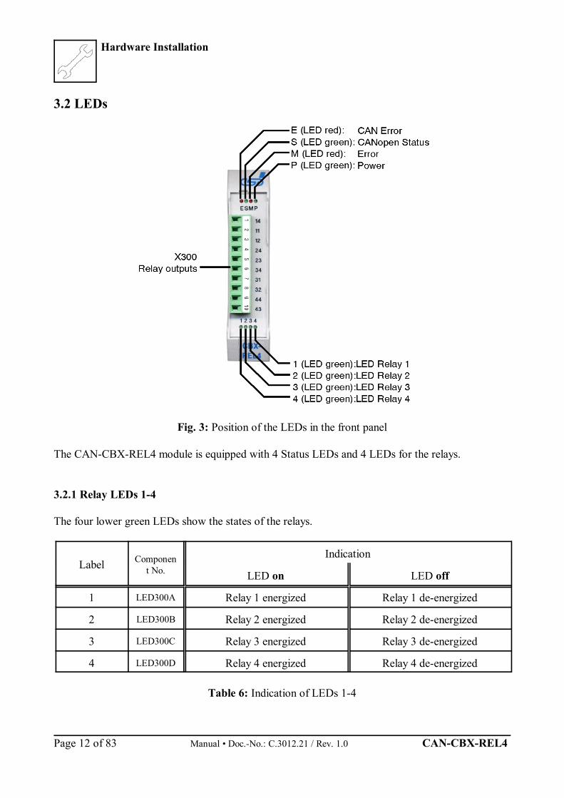
3.2 LEDs
Fig. 3: Position of the LEDs in the front panel
The CAN-CBX-REL4 module is equipped with 4 Status LEDs and 4 LEDs for the relays.
3.2.1 Relay LEDs 1-4
The four lower green LEDs show the states of the relays.
Label Component No.
Indication
LED on LED off
1 LED300A Relay 1 energized Relay 1 de-energized
2 LED300B Relay 2 energized Relay 2 de-energized
3 LED300C Relay 3 energized Relay 3 de-energized
4 LED300D Relay 4 energized Relay 4 de-energized
Table 6: Indication of LEDs 1-4

Hardware Installation
CAN-CBX-REL4 Manual • Doc.-No.: C.3012.21 / Rev. 1.0 Page 13 of 83
3.2.2 Indicator States of the Status-LEDs
The terms of the indicator states of the LEDs are chosen in accordance with the CANopen-Standard DS-303-3 (chapter 3.1). The indicator states are described in the following chapters.
In principle there are 8 indicator states distinguished:
Indicator state Displayon LED onoff LED offblinking LED blinking with a frequency of approx. 2.5 Hzflickering LED flickering with 10 Hz1 flash LED 200 ms on, 1400 ms off2 flashes LED 200 ms on, 200 ms off, 200 ms on, 1000 ms off 3 flashes LED 2x (200 ms on, 200 ms off) + 1x (200 ms on, 1000 ms off) 4 flashes LED 3x (200 ms on, 200 ms off) + 1x (200 ms on, 1000 ms off)
Table 7: Indicator states of the LEDs
CAN-Error-LED
LED indication Display function
Label Name Colour ComponentNo.
Indicatorstate Description
E CAN Error red 200A
off no error
1 flash CAN controller is in Error Active state
onCAN controller state is Bus Off (or coding switch configuration ID-Node > 7Fh
when switching on; see page 15)
2 flashesHeartbeat or Nodeguard error occurred. The LED automatically turns off, ifNodeguard/Heartbeat-messages are received again.
Table 8: Indicator states of the red CAN Error-LED
Hardware Installation
Manual • Doc.-No.: C.3012.21 / Rev. 1.0 CAN-CBX-REL4 Page 14 of 83
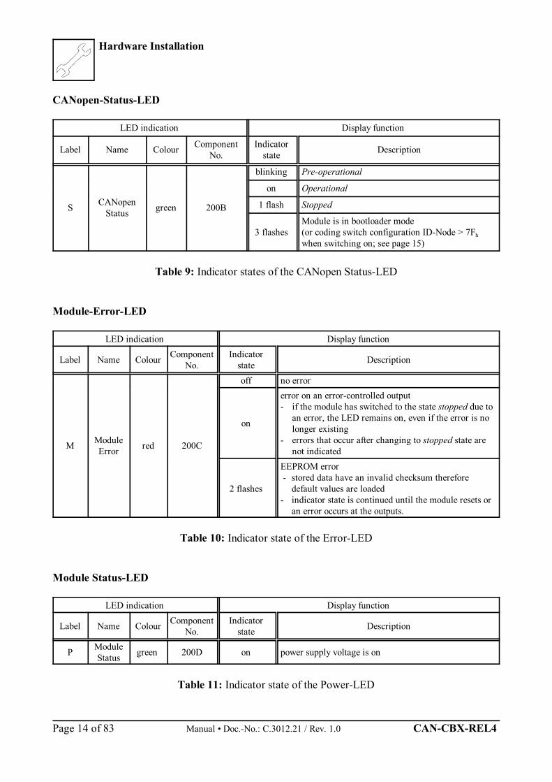
CANopen-Status-LED
LED indication Display function
Label Name Colour ComponentNo.
Indicatorstate Description
S CANopenStatus green 200B
blinking Pre-operational
on Operational
1 flash Stopped
3 flashesModule is in bootloader mode(or coding switch configuration ID-Node > 7Fh
when switching on; see page 15)
Table 9: Indicator states of the CANopen Status-LED
Module-Error-LED
LED indication Display function
Label Name Colour ComponentNo.
Indicatorstate Description
M ModuleError red 200C
off no error
on
error on an error-controlled output- if the module has switched to the state stopped due to
an error, the LED remains on, even if the error is nolonger existing
- errors that occur after changing to stopped state arenot indicated
2 flashes
EEPROM error - stored data have an invalid checksum therefore
default values are loaded- indicator state is continued until the module resets or
an error occurs at the outputs.
Table 10: Indicator state of the Error-LED
Module Status-LED
LED indication Display function
Label Name Colour ComponentNo.
Indicatorstate Description
P ModuleStatus green 200D on power supply voltage is on
Table 11: Indicator state of the Power-LED
Hardware Installation
CAN-CBX-REL4 Manual • Doc.-No.: C.3012.21 / Rev. 1.0 Page 15 of 83
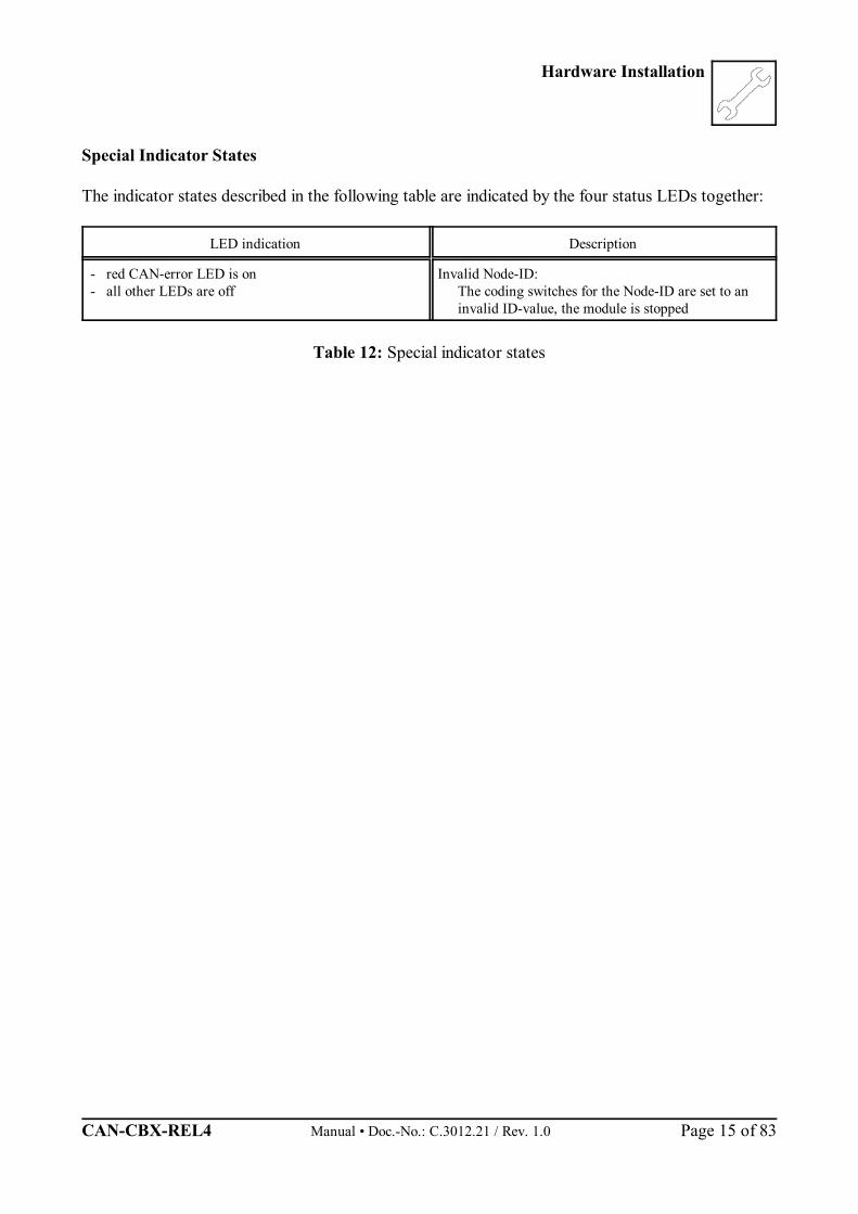
Special Indicator States
The indicator states described in the following table are indicated by the four status LEDs together:
LED indication Description
- red CAN-error LED is on- all other LEDs are off
Invalid Node-ID:The coding switches for the Node-ID are set to aninvalid ID-value, the module is stopped
Table 12: Special indicator states

Hardware Installation
Manual • Doc.-No.: C.3012.21 / Rev. 1.0 CAN-CBX-REL4 Page 16 of 83
3.3 Coding Switches
Fig. 4: Position of the coding switches
Attention!At the moment the module is switched ‘on’, the state of the coding switches isdetermined. Changes of the settings therefore have to be made before switching on themodule, because changes of the settings are not determined during operation.After a reset (e.g. NMT reset) the settings are read again.
3.3.1 Setting the Node-ID via Coding Switch
The address range of the CAN-CBX-REL4 modules can be set hexadecimal from 01h to 7Fh (decimalfrom 1 to 127).
The four higher-order bits (higher-order nibble) can be set with coding switch HIGH, the four lower-order bits can be set with coding switch LOW.
Hardware Installation
CAN-CBX-REL4 Manual • Doc.-No.: C.3012.21 / Rev. 1.0 Page 17 of 83
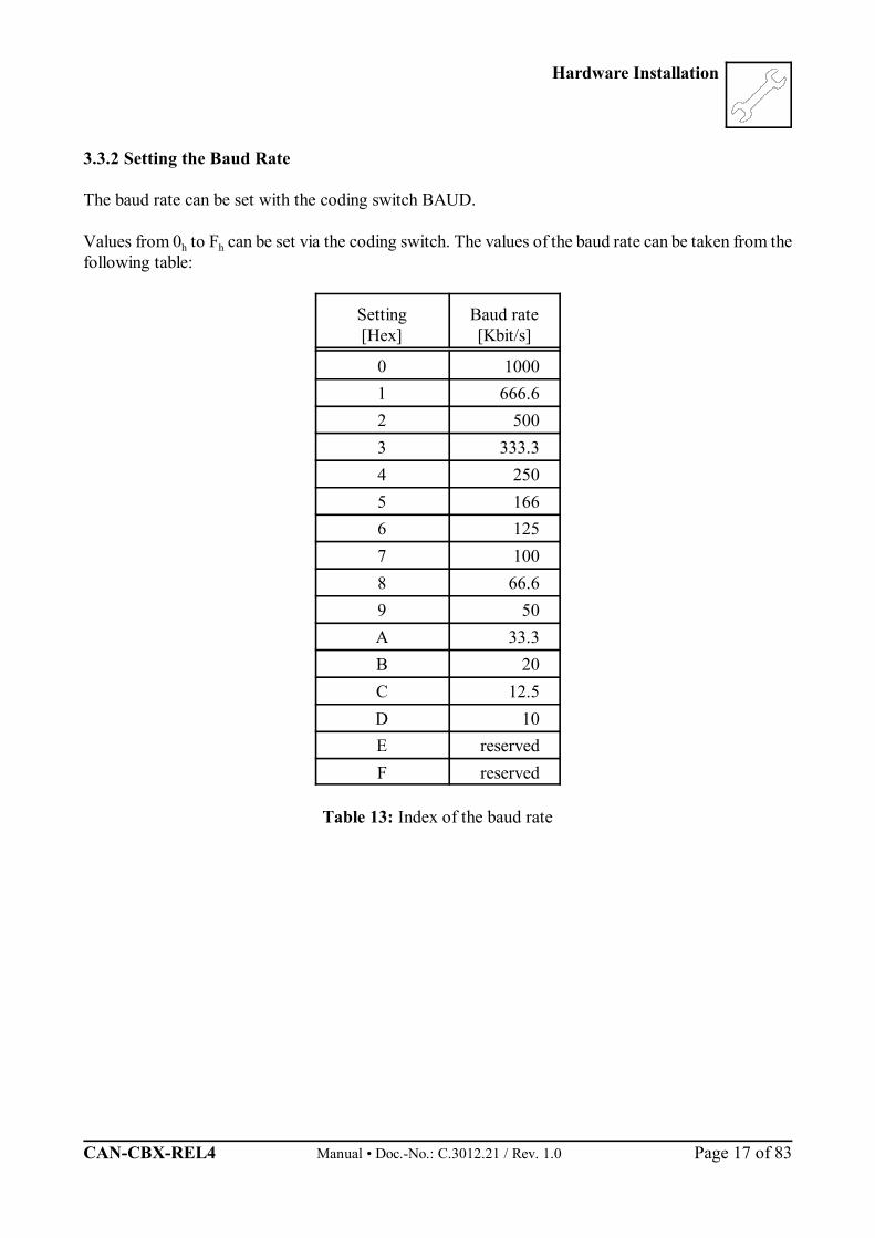
3.3.2 Setting the Baud Rate
The baud rate can be set with the coding switch BAUD.
Values from 0h to Fh can be set via the coding switch. The values of the baud rate can be taken from thefollowing table:
Setting[Hex]
Baud rate[Kbit/s]
0 10001 666.62 5003 333.34 2505 1666 1257 1008 66.69 50A 33.3B 20C 12.5D 10E reservedF reserved
Table 13: Index of the baud rate
Hardware Installation
Manual • Doc.-No.: C.3012.21 / Rev. 1.0 CAN-CBX-REL4 Page 18 of 83
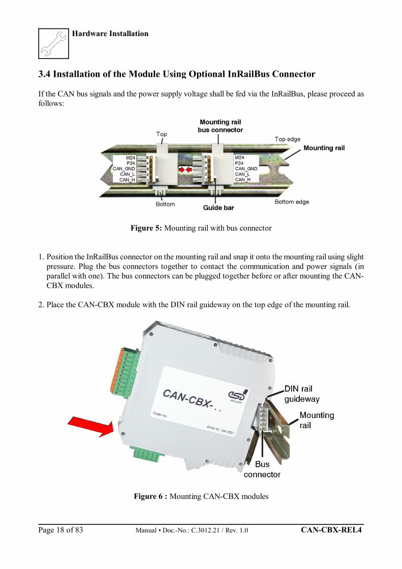
3.4 Installation of the Module Using Optional InRailBus Connector
If the CAN bus signals and the power supply voltage shall be fed via the InRailBus, please proceed asfollows:
Figure 5: Mounting rail with bus connector
1. Position the InRailBus connector on the mounting rail and snap it onto the mounting rail using slightpressure. Plug the bus connectors together to contact the communication and power signals (inparallel with one). The bus connectors can be plugged together before or after mounting the CAN-CBX modules.
2. Place the CAN-CBX module with the DIN rail guideway on the top edge of the mounting rail.
Figure 6 : Mounting CAN-CBX modules
Hardware Installation
CAN-CBX-REL4 Manual • Doc.-No.: C.3012.21 / Rev. 1.0 Page 19 of 83
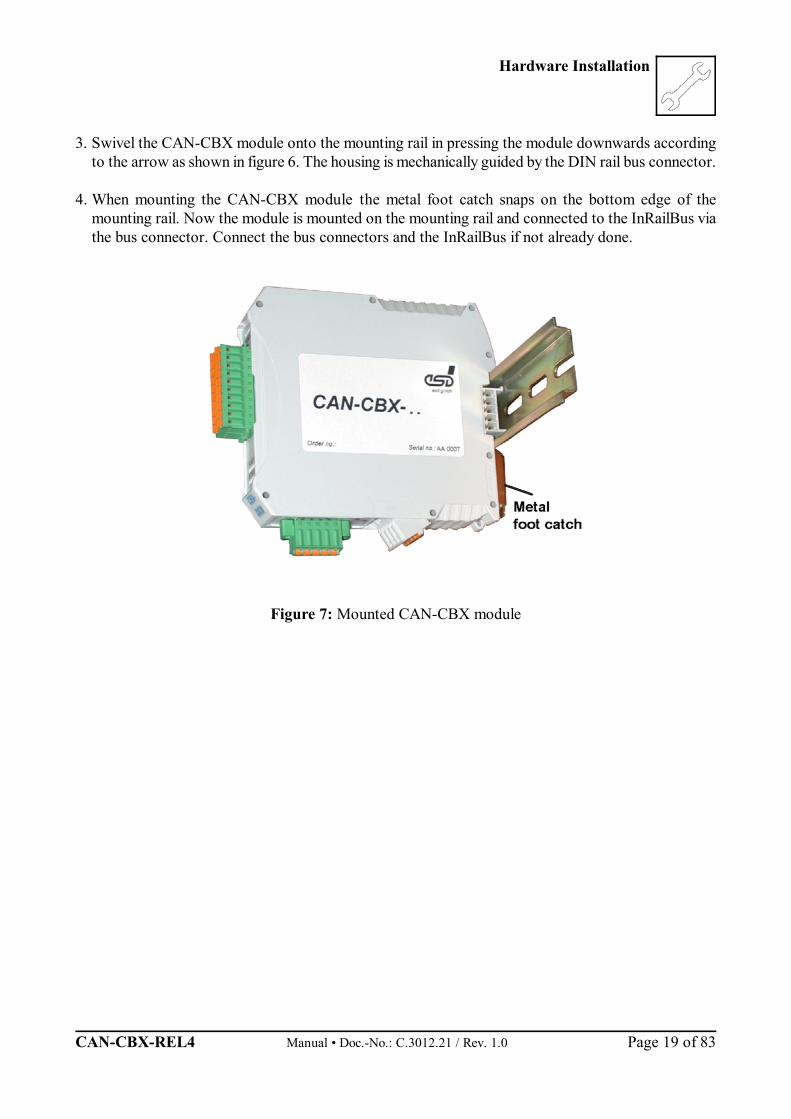
3. Swivel the CAN-CBX module onto the mounting rail in pressing the module downwards accordingto the arrow as shown in figure 6. The housing is mechanically guided by the DIN rail bus connector.
4. When mounting the CAN-CBX module the metal foot catch snaps on the bottom edge of themounting rail. Now the module is mounted on the mounting rail and connected to the InRailBus viathe bus connector. Connect the bus connectors and the InRailBus if not already done.
Figure 7: Mounted CAN-CBX module
Hardware Installation
Manual • Doc.-No.: C.3012.21 / Rev. 1.0 CAN-CBX-REL4 Page 20 of 83
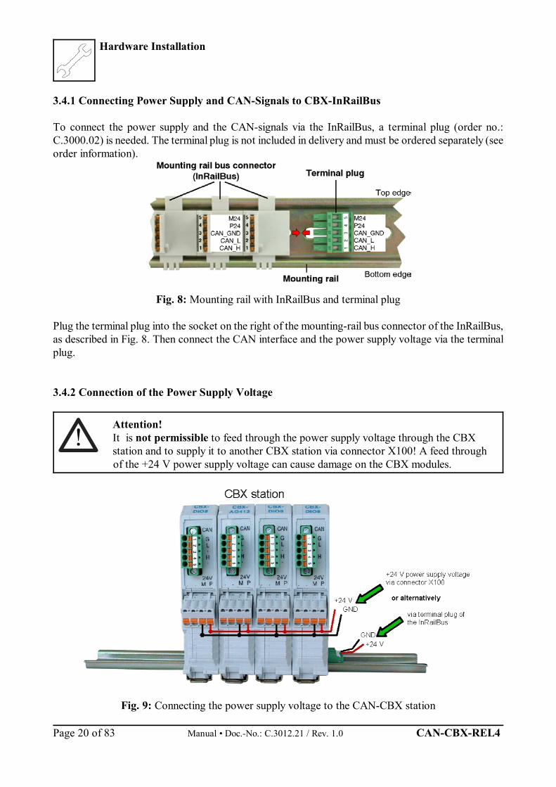
3.4.1 Connecting Power Supply and CAN-Signals to CBX-InRailBus
To connect the power supply and the CAN-signals via the InRailBus, a terminal plug (order no.:C.3000.02) is needed. The terminal plug is not included in delivery and must be ordered separately (seeorder information).
Fig. 8: Mounting rail with InRailBus and terminal plug
Plug the terminal plug into the socket on the right of the mounting-rail bus connector of the InRailBus,as described in Fig. 8. Then connect the CAN interface and the power supply voltage via the terminalplug.
3.4.2 Connection of the Power Supply Voltage
Attention!It is not permissible to feed through the power supply voltage through the CBXstation and to supply it to another CBX station via connector X100! A feed throughof the +24 V power supply voltage can cause damage on the CBX modules.
Fig. 9: Connecting the power supply voltage to the CAN-CBX station
Hardware Installation
CAN-CBX-REL4 Manual • Doc.-No.: C.3012.21 / Rev. 1.0 Page 21 of 83
i
3.4.3 Connection of CAN
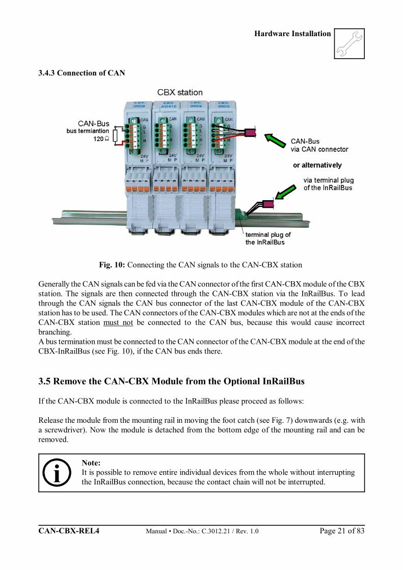
Fig. 10: Connecting the CAN signals to the CAN-CBX station
Generally the CAN signals can be fed via the CAN connector of the first CAN-CBX module of the CBXstation. The signals are then connected through the CAN-CBX station via the InRailBus. To leadthrough the CAN signals the CAN bus connector of the last CAN-CBX module of the CAN-CBXstation has to be used. The CAN connectors of the CAN-CBX modules which are not at the ends of theCAN-CBX station must not be connected to the CAN bus, because this would cause incorrectbranching.A bus termination must be connected to the CAN connector of the CAN-CBX module at the end of theCBX-InRailBus (see Fig. 10), if the CAN bus ends there.
3.5 Remove the CAN-CBX Module from the Optional InRailBus
If the CAN-CBX module is connected to the InRailBus please proceed as follows:
Release the module from the mounting rail in moving the foot catch (see Fig. 7) downwards (e.g. witha screwdriver). Now the module is detached from the bottom edge of the mounting rail and can beremoved.
Note:It is possible to remove entire individual devices from the whole without interruptingthe InRailBus connection, because the contact chain will not be interrupted.

Description of the Units
Manual • Doc.-No.: C.3012.21 / Rev. 1.0 CAN-CBX-REL4 Page 22 of 83
VIB
VOA
GND1
VOB
VIA
VDD2
GND2
VDD
TX
R/GND
BUSL
RX BUSH
5V
++
- -
+5V
CAN_GND
DC/DCRSS-0505
GND
5V
5.0V
GND
VC120605
10µF
2.2M
2.2nF/250V~
CAN TransceiverPCA82C251
100nF
VDD1
CAN_Tx
CAN_RxCAN_L
CAN_H
2
4
CAN_GND1
4+24 V
5GND
CAN_L
CAN_H
3
1
CAN_GND
2
X600
PE_GND3
5.0V
Digital IsolatorADUM1201Br
100nF
Functional Earth
X101Bus Connector MEMAX
4. Description of the Units
4.1 CAN Interface
An 82C251 is used as driver unit. The differential CAN bus signals are electrically isolated from theother signals via a dual digital converter (ADUM120BR) and a DC/DC converter.
Fig. 11: CAN interface

Connector Pin Assignment
CAN-CBX-REL4 Manual • Doc.-No.: C.3012.21 / Rev. 1.0 Page 23 of 83
i
5. Connector Pin Assignment
5.1 Power Supply Voltage X100
Device connector: COMBICON MSTBO 2,5/4-G1L-KMGYLine connector: COMBICON FKCT 2,5/4-ST, 5.0 mm pitch, spring-cage connection,
PHOENIX-CONTACT order no.: 19 21 90 0 (included in the scope ofdelivery)
Pin Position:
Pin Assignment:
Pin 4 3 2 1
Signal P24(+ 24 V)
M24 (GND)
M24 (GND)
P24(+ 24 V)
Please refer also to the connecting diagram on page 11.
Note: The pins 1 and 4 are connected to each other at the PCB.The pins 2 and 3 are connected to each other at the PCB.
Signal Description:
P24... power supply voltage +24 VM24... reference potential

Connector Pin Assignment
Manual • Doc.-No.: C.3012.21 / Rev. 1.0 CAN-CBX-REL4 Page 24 of 83
12345
5.2 CAN-Bus X600
Device Connector: COMBICON MC 1,5/5-GF-3,81Line Connector: COMBICON FK-MCP 1,5/5-STF-3,81, spring-cage connection (included in the
scope of delivery)
Pin Position: Pin-Assignment:(Illustration of device
connector) Pin Signal
1 CAN_GND
2 CAN_L
3 Shield
4 CAN_H
5 -
Signal description:
CAN_L, CAN_H ... CAN signalsCAN_GND ... reference potential of the local CAN physical layerShield ... pin for line shield connection (using hat rail mounting direct contact to the
mounting rail potential)- ... not connected
Recommendation of an adapter cable from 5-pin Combicon (here line connector FK-MCP1,5/5-STF-3,81 with spring-cage-connection) to 9-pin DSUB:
Assignment ofthe 9-pinDSUB-connectoraccording toCiA DS 102.
Connector Pin Assignment
CAN-CBX-REL4 Manual • Doc.-No.: C.3012.21 / Rev. 1.0 Page 25 of 83
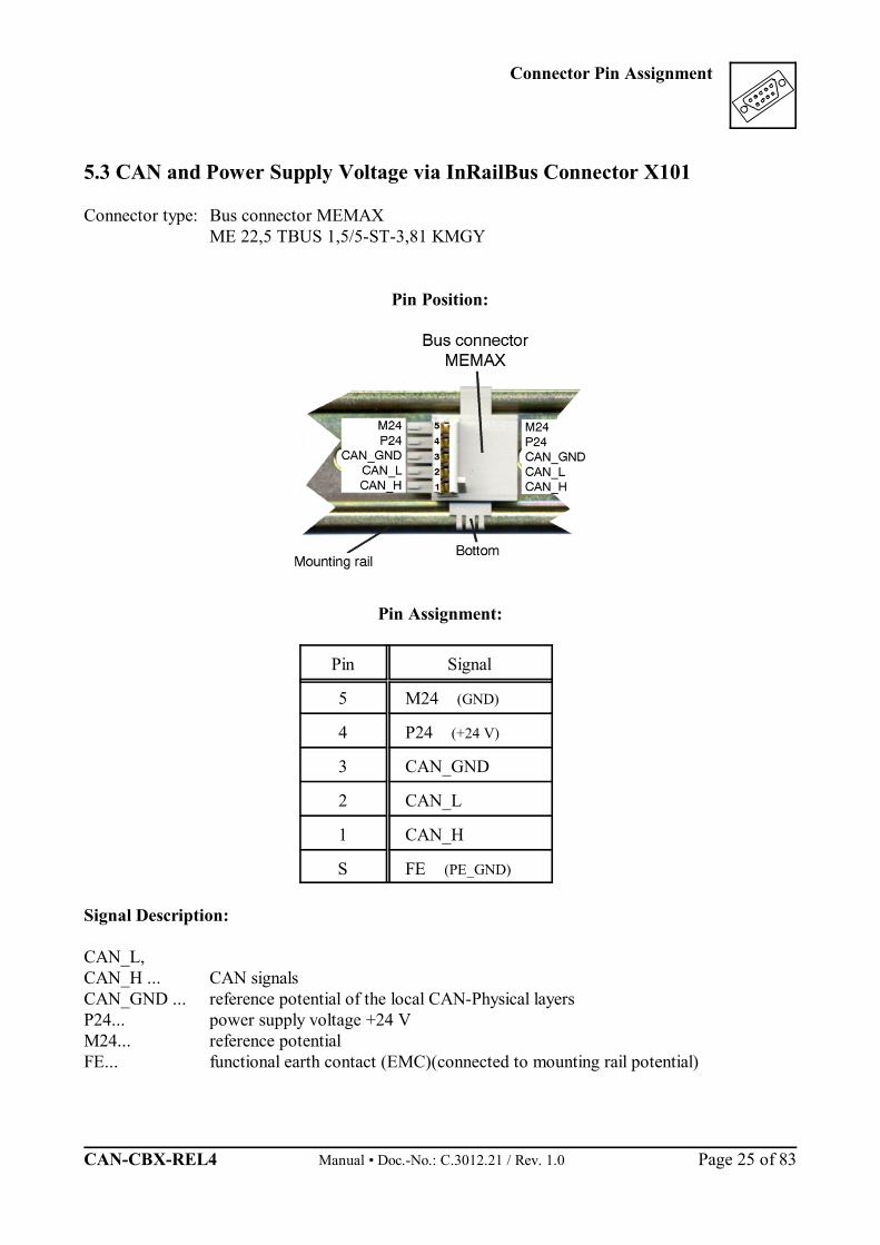
5.3 CAN and Power Supply Voltage via InRailBus Connector X101
Connector type: Bus connector MEMAXME 22,5 TBUS 1,5/5-ST-3,81 KMGY
Pin Position:
Pin Assignment:
Pin Signal
5 M24 (GND)
4 P24 (+24 V)
3 CAN_GND
2 CAN_L
1 CAN_H
S FE (PE_GND)
Signal Description:
CAN_L, CAN_H ... CAN signalsCAN_GND ... reference potential of the local CAN-Physical layersP24... power supply voltage +24 VM24... reference potentialFE... functional earth contact (EMC)(connected to mounting rail potential)

Connector Pin Assignment
Manual • Doc.-No.: C.3012.21 / Rev. 1.0 CAN-CBX-REL4 Page 26 of 83
5.4 Relay Outputs X300
Device connector: Mini-COMBICON MC 1,5/10-G-5,08Line connector: Mini-COMBICON MC 1,5/10-ST-5,08
(included in the scope of delivery)
Pin Assignment:
Pin Position: Pin Labelling Signal
1 14 NO
Relay 12 11 COM
3 12 NC
4 24 NORelay 2
5 23 COM
6 34 NO
Relay 37 31 COM
8 32 NC
9 44 NORelay 4
10 43 COM

Wiring
CAN-CBX-REL4 Manual • Doc.-No.: C.3012.21 / Rev. 1.0 Page 27 of 83
9
1
4567
9
23
8
1
4567
23
8
CAN_L
CAN_H
CAN_GND
Shielded wire withtransposed wires
CAN_L
CAN_H
CAN_GND(at wire shield)
120
Ohm
120
Ohm
earth (PE)
Wire structure Signal assignment of wire and connection of earthing and terminator
n.c.
n.c.
n.c.
n.c.
n.c.
n.c.
n.c.
n.c.
n.c.
n.c.
n.c.
n.c.
n.c.
n.c.
n.c. = not connected
DSUB9 connector(female or male)pin designation
connector case connector case
DSUB9 connector(female or male)pin designation
CAN wire with connectors
6. Correctly Wiring Electrically Isolated CAN NetworksGenerally all instructions applying for wiring regarding an electromagnetic compatible installation,wiring, cross sections of wires, material to be used, minimum distances, lightning protection, etc. haveto be followed.
The following general rules for the CAN wiring must be followed:
1.A CAN net must not branch (exception: short dead-end feeders) and has to be terminatedby the wave impedance of the wire (generally 120 W ±10%) at both ends (between thesignals CAN_L and CAN_H and not at GND)!
2.A CAN data wire requires two twisted wires and a wire to conduct the reference potential(CAN_GND)! For this the shield of the wire should be used!
3. The reference potential CAN_GND has to be connected to the earth potential (PE) at onepoint. Exactly one connection to earth has to be established!
4. The bit rate has to be adapted to the wire length.
5. Dead-end feeders have to kept as short as possible (l < 0.3 m)!
6. When using double shielded wires the external shield has to be connected to the earthpotential (PE) at one point. There must be not more than one connection to earth.
7. A suitable type of wire (wave impedance ca. 120 ±10%) has to be used and the voltageloss in the wire has to be considered!
8. CAN wires should not be laid directly next to disturbing sources. If this cannot be avoided,double shielded wires are preferable.
Figure: Structure and connection of wire
Wiring
Manual • Doc.-No.: C.3012.21 / Rev. 1.0 CAN-CBX-REL4 Page 28 of 83
l < 0,3 m
CAN_L
CAN_GND
CAN_H
PE
l < 0,3 m
CAN-CBM-AI4
CAN-CBM-COM1
CAN-CBM-DIO8
l < 0,3 ml < 0,3 ml < 0,3 m
Female Connector
Male Connector
e.g.CAN-SPS InterfaceCSC595/2orCAN-PC Board
Terminator
Male Terminator(Order-no.: C.1302.01)
Connecting CAN_GND toProtective Conductor PE
Terminatorwith PE Connector
Female Terminator(Order-no.: C.1301.01)
T-ConnectorC.1311.03
CAN-CableOrder-no.: C.1323.03
Net 2
Net 1 e.g. PCI/405,CAN-USB,
VME-CAN2, etc.
CAN-CableOrder-no.: C.1323.03
CAN-CableOrder-no.: C.1323.03
T-ConnectorC.1311.03
T-ConnectorC.1311.03
T-ConnectorC.1311.03
CAN-Board
T-ConnectorOrder-no.: C.1311.03
Cabling
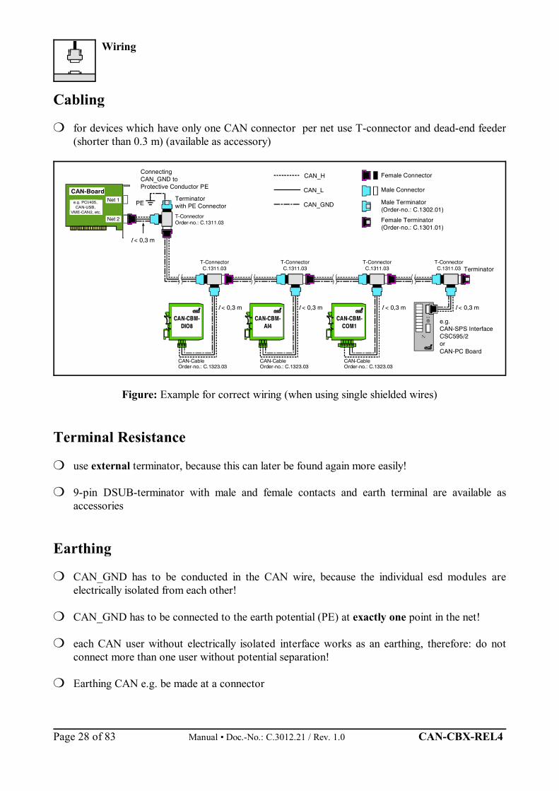
for devices which have only one CAN connector per net use T-connector and dead-end feeder(shorter than 0.3 m) (available as accessory)
Figure: Example for correct wiring (when using single shielded wires)
Terminal Resistance
use external terminator, because this can later be found again more easily!
9-pin DSUB-terminator with male and female contacts and earth terminal are available asaccessories
Earthing
CAN_GND has to be conducted in the CAN wire, because the individual esd modules areelectrically isolated from each other!
CAN_GND has to be connected to the earth potential (PE) at exactly one point in the net!
each CAN user without electrically isolated interface works as an earthing, therefore: do notconnect more than one user without potential separation!
Earthing CAN e.g. be made at a connector

Wiring
CAN-CBX-REL4 Manual • Doc.-No.: C.3012.21 / Rev. 1.0 Page 29 of 83
Wire Length
Optical couplers are delaying the CAN signals. By using fast optical couplers and testing each boardat 1 Mbit/s, however, esd CAN guarantee a reachable length of 37 m at 1 Mbit/s for most esd CANmodules within a closed net without impedance disturbances like e.g. longer dead-end feeders.(Exception: CAN-CBM-DIO8, -AI4 and AO4 (these modules work only up to 10 m with 1 Mbit/s))
Bit rate[Kbit/s]
Typical values of reachablewire length with esd
interface lmax [m]
CiA recommendations(07/95) for reachable wire
lengths lmin [m]
1000 800
666.6 500
333.3 250 166 125 100
66.6 50
33.3 20
12.5 10
375980
130180270420570710
100014002000360054007300
2550
-100
-250
-500650
-1000
-2500
-5000
Table: Reachable wire lengths depending on the bit rate when using esd-CAN interfaces
Wiring
Manual • Doc.-No.: C.3012.21 / Rev. 1.0 CAN-CBX-REL4 Page 30 of 83
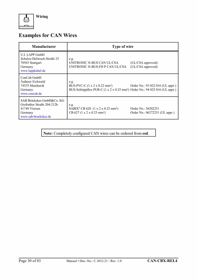
Examples for CAN Wires
Manufacturer Type of wire
U.I. LAPP GmbHSchulze-Delitzsch-Straße 2570565 StuttgartGermanywww.lappkabel.de
e.g.UNITRONIC ®-BUS CAN UL/CSA (UL/CSA approved)UNITRONIC ®-BUS-FD P CAN UL/CSA (UL/CSA approved)
ConCab GmbHÄußerer Eichwald74535 MainhardtGermanywww.concab.de
e.g.BUS-PVC-C (1 x 2 x 0.22 mm²) Order No.: 93 022 016 (UL appr.)BUS-Schleppflex-PUR-C (1 x 2 x 0.25 mm²) Order No.: 94 025 016 (UL appr.)
SAB Bröckskes GmbH&Co. KGGrefrather Straße 204-212b41749 ViersenGermanywww.sab-brockskes.de
e.g.SABIX® CB 620 (1 x 2 x 0.25 mm²) Order No.: 56202251CB 627 (1 x 2 x 0.25 mm²) Order No.: 06272251 (UL appr.)
Note: Completely configured CAN wires can be ordered from esd.
CAN-Bus Troubleshooting Guide
CAN-CBX-REL4 Manual • Doc.-No.: C.3012.21 / Rev. 1.0 Page 31 of 83
120
CAN_H
CAN_GND
CAN_LCAN_L
CAN_H
CAN_GND
V
120
2 3
1
V
1
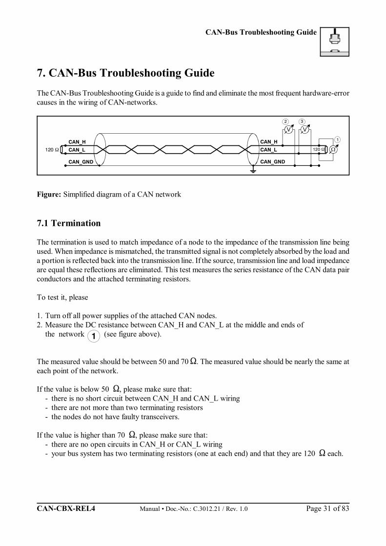
7. CAN-Bus Troubleshooting GuideThe CAN-Bus Troubleshooting Guide is a guide to find and eliminate the most frequent hardware-errorcauses in the wiring of CAN-networks.
Figure: Simplified diagram of a CAN network
7.1 Termination
The termination is used to match impedance of a node to the impedance of the transmission line beingused. When impedance is mismatched, the transmitted signal is not completely absorbed by the load anda portion is reflected back into the transmission line. If the source, transmission line and load impedanceare equal these reflections are eliminated. This test measures the series resistance of the CAN data pairconductors and the attached terminating resistors.
To test it, please
1. Turn off all power supplies of the attached CAN nodes.2. Measure the DC resistance between CAN_H and CAN_L at the middle and ends of
the network (see figure above).
The measured value should be between 50 and 70 . The measured value should be nearly the same ateach point of the network.
If the value is below 50 , please make sure that:- there is no short circuit between CAN_H and CAN_L wiring- there are not more than two terminating resistors - the nodes do not have faulty transceivers.
If the value is higher than 70 , please make sure that:- there are no open circuits in CAN_H or CAN_L wiring - your bus system has two terminating resistors (one at each end) and that they are 120 each.

CAN-Bus Troubleshooting Guide
Manual • Doc.-No.: C.3012.21 / Rev. 1.0 CAN-CBX-REL4 Page 32 of 83
2
3
>1M
CAN_H
CAN_GND
CAN_L
7.2 CAN_H/CAN_L Voltage
Each node contains a CAN transceiver that outputs differential signals. When the networkcommunication is idle the CAN_H and CAN_L voltages are approximately 2.5 volts. Faulty transceiverscan cause the idle voltages to vary and disrupt network communication. To test for faulty transceivers, please
1. Turn on all supplies. 2. Stop all network communication.3. Measure the DC voltage between CAN_H and GND (see figure above).
4. Measure the DC voltage between CAN_L and GND (see figure above).
Normally the voltage should be between 2.0 V and 4.0 V. If it is lower than 2.0 V or higher than 4.0 V, it is possible that one or more nodes have faultytransceivers. For a voltage lower than 2.0 V please check CAN_H and CAN_L conductors forcontinuity. For a voltage higher than 4.0 V, please check for excessive voltage.
To find the node with a faulty transceiver please test the CAN transceiver resistance (see next page).
7.3 Ground
The shield of the CAN network has to be grounded at only one location. This test will indicate if theshielding is grounded in several places. To test it, please
1. Disconnect the shield wire(Shield) from the ground.
2. Measure the DC resistancebetween Shield and ground (seepicture on the right hand).
3. Connect Shield wire to ground.
Fig.: Simplified schematic diagram of ground test measurement
The resistance should be higher than 1 M . If it is lower, please search for additional grounding of theshield wires.
CAN-Bus Troubleshooting Guide
CAN-CBX-REL4 Manual • Doc.-No.: C.3012.21 / Rev. 1.0 Page 33 of 83
4
5
6
CAN_H
CAN_GND
CAN_L
5 6
4
4
Power
CAN-Transceiver
Disconnect Power !
Disconnect CAN !
CAN-node
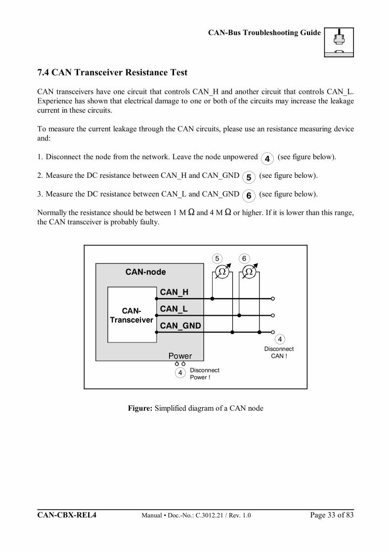
7.4 CAN Transceiver Resistance Test
CAN transceivers have one circuit that controls CAN_H and another circuit that controls CAN_L.Experience has shown that electrical damage to one or both of the circuits may increase the leakagecurrent in these circuits.
To measure the current leakage through the CAN circuits, please use an resistance measuring deviceand:
1. Disconnect the node from the network. Leave the node unpowered (see figure below).
2. Measure the DC resistance between CAN_H and CAN_GND (see figure below).
3. Measure the DC resistance between CAN_L and CAN_GND (see figure below).
Normally the resistance should be between 1 M and 4 M or higher. If it is lower than this range,the CAN transceiver is probably faulty.
Figure: Simplified diagram of a CAN node
Software
Manual • Doc.-No.: C.3012.21 / Rev. 1.0 CAN-CBX-REL4 Page 34 of 83
8. Software Apart from basic descriptions of the CANopen, this chapter contains the most significant informationabout the implemented functions.
A complete CANopen description is too extensive for the purpose of this manual.Further information can therefore be taken from the CAL / CANopen documentation ‘CiA DraftStandard 301, V 4.02’ and ‘CiA Draft Standard Proposal 401, V 2.1’.
8.1 Definition of Terms
COB ... Communication ObjectEmergency-Id... Emergency Data ObjectNMT... Network Management (Master)Rx... receiveSDO... Service Data ObjectSync... Sync(frame) TelegramTx... transmit
PDOs (Process Data Objects)PDOs are used to transmit process data. In the ‘Receive’-PDO (RxPDO) process data is received by the CAN-CBX-module.
SDOs (Service Data Objects)SDOs are used to transmit module internal configuration- and parameter data. In opposition tothe PDOs SDO-messages are confirmed. A write or read request on a data object is alwaysanswered by a response telegram with an error index.
Software
CAN-CBX-REL4 Manual • Doc.-No.: C.3012.21 / Rev. 1.0 Page 35 of 83
8.2 NMT-Boot-up
The CAN-CBX-REL4 module can be initialized with the ‘Minimum Capability Device’ boot-up asdescribed in CiA-Draft Standard 301 in chapter 9.4.
Usually a telegram to switch from Pre-Operational status to Operational status after boot-up issufficient. For this the 2-byte telegram ‘01h’, ‘00h’, for example, has to be transmitted on CAN-identifier‘0000h’ (= Start Remote Node all Devices).
8.3 CANopen Object Directory
The object directory is basically a (sorted) group of objects which can be accessed via the network. Eachobject in this directory is addressed with a 16-bit index. The index in the object directories is representedin hexadecimal format.
The index can be a 16-bit parameter in accordance with the CANopen specification (CiA-Draft DS 301)or a manufacturer-specific code. By means of the MSBs of the index the object class of the parameteris defined.
Part of the object directory are among others:
Index [Hex] Object Example
0001 ... 009F Definition of data types -
1000 ... 1FFF Communication Profile Area 1001h : Error register
2000 ... 5FFF Manufacturer Specific Profile Area -
6000 ... 9FFF Standardized Device Profile Area according to application profileDS 40x
A000 ... FFFF reserved -
8.3.1 Access on the Object Directory via SDOs
SDOs (Service Data Objects) are used to get access to the object directory of a device.An SDO therefore represents a ‘channel’ to access the parameter of the device. The access via thischannel can be made in CAN-CBX-REL4 module state operational and pre-operational.
The SDOs are transmitted on ID ‘600h + NodeID’ (request). The receiver acknowledges the parameteron ID ‘580h + NodeID’ (response).
Software
Manual • Doc.-No.: C.3012.21 / Rev. 1.0 CAN-CBX-REL4 Page 36 of 83
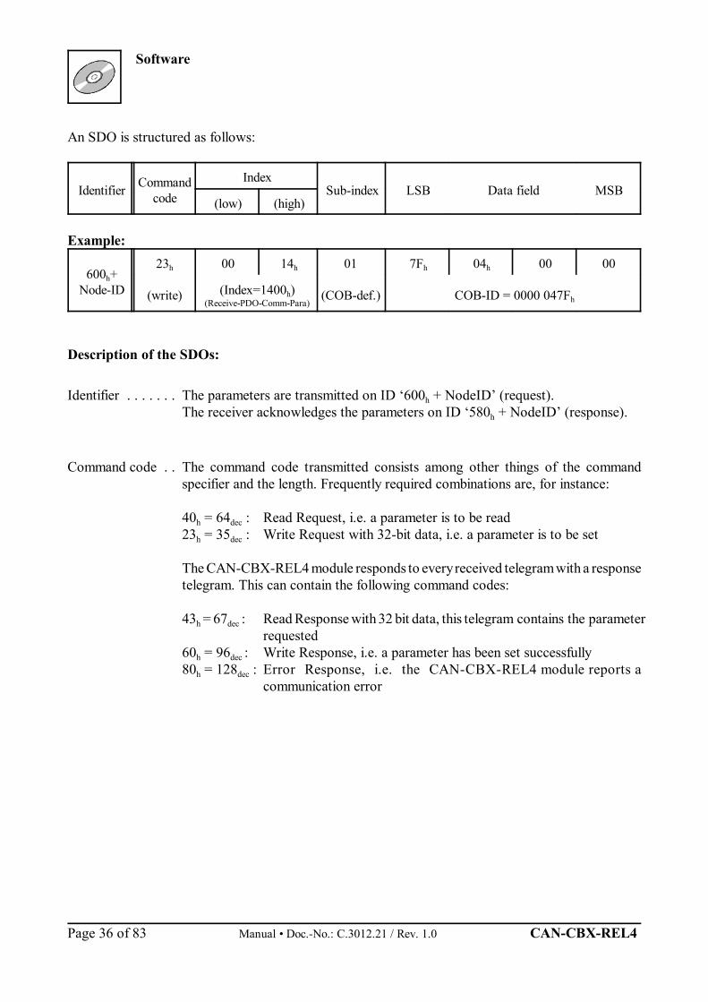
An SDO is structured as follows:
Identifier Commandcode
IndexSub-index LSB Data field MSB
(low) (high)
Example:
600h+Node-ID
23h 00 14h 01 7Fh 04h 00 00
(write) (Index=1400h)(Receive-PDO-Comm-Para)
(COB-def.) COB-ID = 0000 047Fh
Description of the SDOs:
Identifier . . . . . . . The parameters are transmitted on ID ‘600h + NodeID’ (request). The receiver acknowledges the parameters on ID ‘580h + NodeID’ (response).
Command code . . The command code transmitted consists among other things of the commandspecifier and the length. Frequently required combinations are, for instance:
40h = 64dec : Read Request, i.e. a parameter is to be read23h = 35dec : Write Request with 32-bit data, i.e. a parameter is to be set
The CAN-CBX-REL4 module responds to every received telegram with a responsetelegram. This can contain the following command codes:
43h = 67dec : Read Response with 32 bit data, this telegram contains the parameterrequested
60h = 96dec : Write Response, i.e. a parameter has been set successfully80h = 128dec : Error Response, i.e. the CAN-CBX-REL4 module reports a
communication error

Software
CAN-CBX-REL4 Manual • Doc.-No.: C.3012.21 / Rev. 1.0 Page 37 of 83
Frequently Used Command CodesThe following table summarizes frequently used command codes. The commandframes must always contain 8 data bytes. Notes on the syntax and further commandcodes can be found in CiA DS 301, chapter “Service Data Object”.
Command Number of databytes
Command code[Hex]
Write Request(Initiate Domain Download)
1234
2F2B2723
Write Response(Initiate Domain Download) - 60
Read Request(Initiate Domain Upload) - 40
Read Response(Initiate Domain Upload)
1234
4F4B4743
Error Response(Abort Domain Transfer) - 80
Index, Sub-Index . Index and sub-index will be described in the chapters “Device Profile Area” and“Manufacturer Specific Objects” of this manual.
Data Field . . . . . . The data field has got a size of a maximum of 4 bytes and is always structured ‘LSBfirst, MSB last’. The least significant byte is always in ‘Data 1’. With 16-bit valuesthe most significant byte (bits 8...15) is always in ‘Data 2’, and with 32-bit valuesthe MSB (bits 24...31) is always in ‘Data 4’.
Software
Manual • Doc.-No.: C.3012.21 / Rev. 1.0 CAN-CBX-REL4 Page 38 of 83
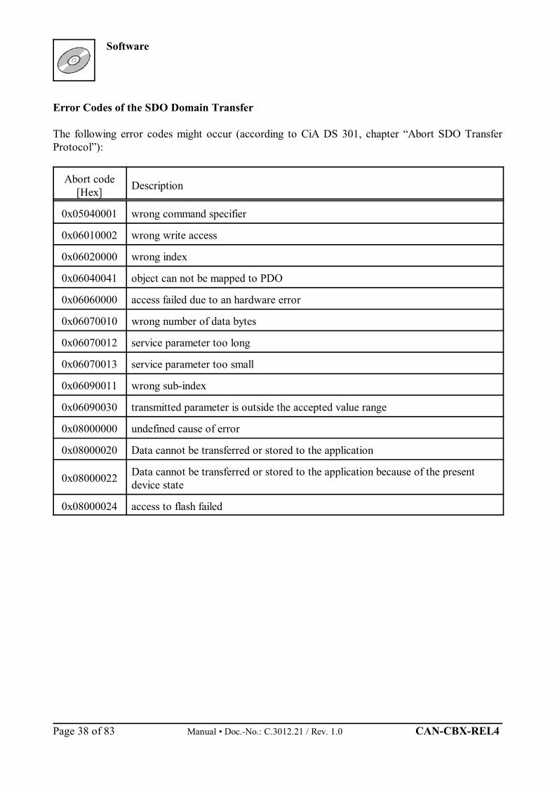
Error Codes of the SDO Domain Transfer
The following error codes might occur (according to CiA DS 301, chapter “Abort SDO TransferProtocol”):
Abort code[Hex] Description
0x05040001 wrong command specifier
0x06010002 wrong write access
0x06020000 wrong index
0x06040041 object can not be mapped to PDO
0x06060000 access failed due to an hardware error
0x06070010 wrong number of data bytes
0x06070012 service parameter too long
0x06070013 service parameter too small
0x06090011 wrong sub-index
0x06090030 transmitted parameter is outside the accepted value range
0x08000000 undefined cause of error
0x08000020 Data cannot be transferred or stored to the application
0x08000022 Data cannot be transferred or stored to the application because of the presentdevice state
0x08000024 access to flash failed
Software
CAN-CBX-REL4 Manual • Doc.-No.: C.3012.21 / Rev. 1.0 Page 39 of 83
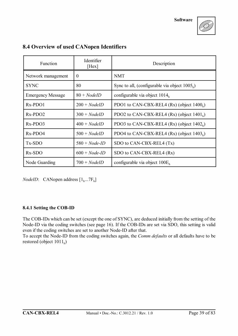
8.4 Overview of used CANopen Identifiers
Function Identifier[Hex] Description
Network management 0 NMT
SYNC 80 Sync to all, (configurable via object 1005h)
Emergency Message 80 + NodeID configurable via object 1014h
Rx-PDO1 200 + NodeID PDO1 to CAN-CBX-REL4 (Rx) (object 1400h)
Rx-PDO2 300 + NodeID PDO2 to CAN-CBX-REL4 (Rx) (object 1401h)
Rx-PDO3 400 + NodeID PDO3 to CAN-CBX-REL4 (Rx) (object 1402h)
Rx-PDO4 500 + NodeID PDO4 to CAN-CBX-REL4 (Rx) (object 1403h)
Tx-SDO 580 + Node-ID SDO to CAN-CBX-REL4 (Tx)
Rx-SDO 600 + Node-ID SDO to CAN-CBX-REL4 (Rx)
Node Guarding 700 + NodeID configurable via object 100Eh
NodeID: CANopen address [1h...7Fh]
8.4.1 Setting the COB-ID
The COB-IDs which can be set (except the one of SYNC), are deduced initially from the setting of theNode-ID via the coding switches (see page 16). If the COB-IDs are set via SDO, this setting is valideven if the coding switches are set to another Node-ID after that.To accept the Node-ID from the coding switches again, the Comm defaults or all defaults have to berestored (object 1011h)
Software
Manual • Doc.-No.: C.3012.21 / Rev. 1.0 CAN-CBX-REL4 Page 40 of 83
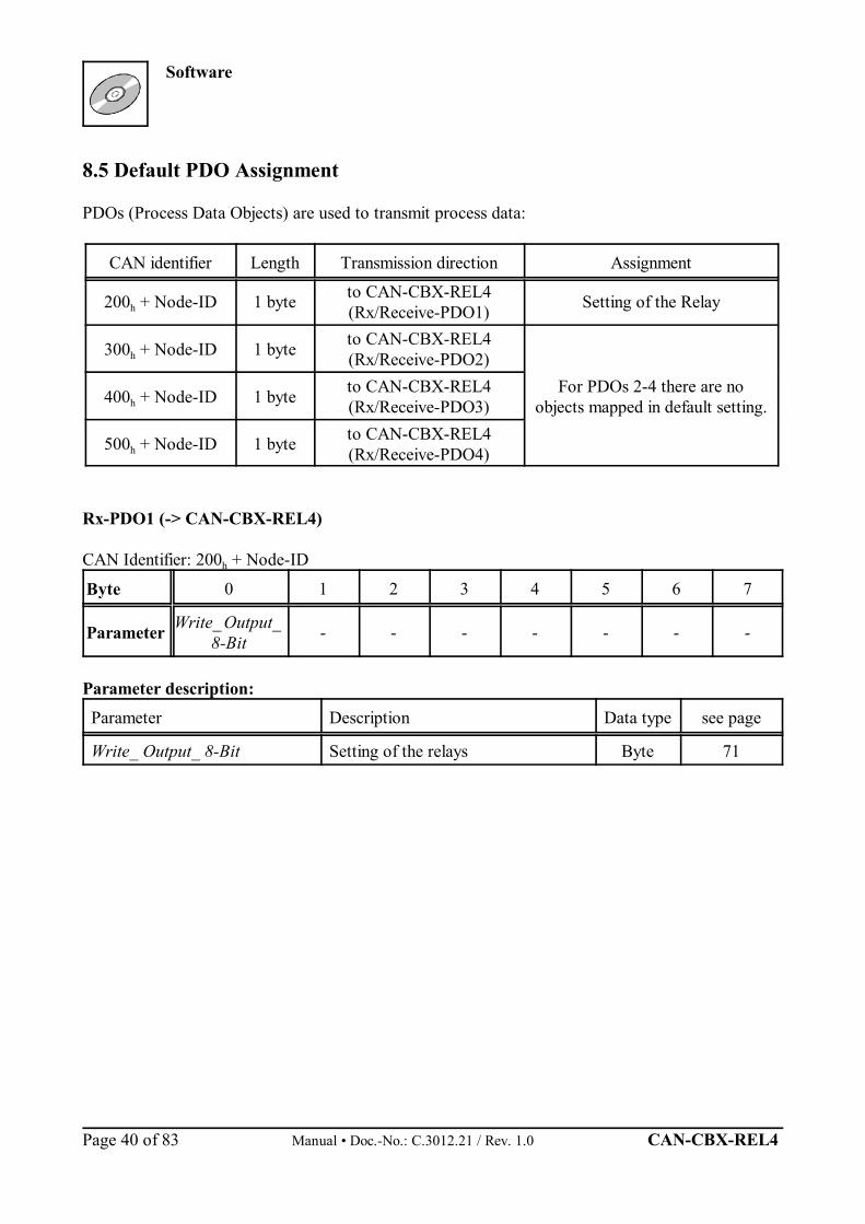
8.5 Default PDO Assignment
PDOs (Process Data Objects) are used to transmit process data:
CAN identifier Length Transmission direction Assignment
200h + Node-ID 1 byte to CAN-CBX-REL4(Rx/Receive-PDO1) Setting of the Relay
300h + Node-ID 1 byte to CAN-CBX-REL4(Rx/Receive-PDO2)
For PDOs 2-4 there are noobjects mapped in default setting.400h + Node-ID 1 byte to CAN-CBX-REL4
(Rx/Receive-PDO3)
500h + Node-ID 1 byte to CAN-CBX-REL4(Rx/Receive-PDO4)
Rx-PDO1 (-> CAN-CBX-REL4)
CAN Identifier: 200h + Node-ID
Byte 0 1 2 3 4 5 6 7
Parameter Write_ Output_ 8-Bit - - - - - - -
Parameter description:Parameter Description Data type see page
Write_ Output_ 8-Bit Setting of the relays Byte 71
Software
CAN-CBX-REL4 Manual • Doc.-No.: C.3012.21 / Rev. 1.0 Page 41 of 83
8.6 Setting the Relays
The relays will be energized, as soon as an output setting object is received by the CAN-CBX-REL4(e.g. object 6200h via Rx-PDO).
8.6.1 Supported Transmission Types Based on DS-301
Transmission type Synchronous means that the CANopen device shall actuate the received data withthe reception of the next SYNC.Transmission type Event-driven means that the PDO may be received at any time. The CANopen devicewill actualize the data immediately.
Implemented CANopen Objects
Manual • Doc.-No.: C.3012.21 / Rev. 1.0 CAN-CBX-REL4 Page 42 of 83
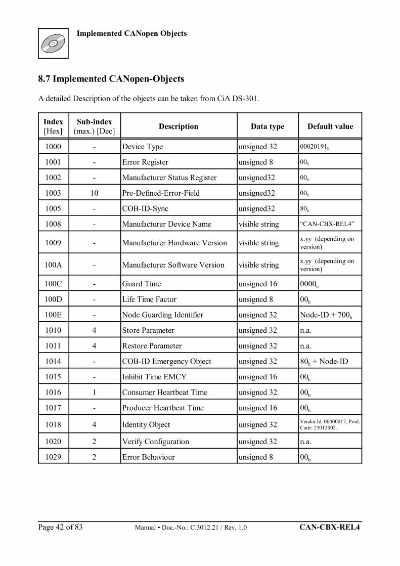
8.7 Implemented CANopen-Objects
A detailed Description of the objects can be taken from CiA DS-301.
Index[Hex]
Sub-index(max.) [Dec] Description Data type Default value
1000 - Device Type unsigned 32 00020191h
1001 - Error Register unsigned 8 00h
1002 - Manufacturer Status Register unsigned32 00h
1003 10 Pre-Defined-Error-Field unsigned32 00h
1005 - COB-ID-Sync unsigned32 80h
1008 - Manufacturer Device Name visible string “CAN-CBX-REL4”
1009 - Manufacturer Hardware Version visible string x.yy (depending onversion)
100A - Manufacturer Software Version visible string x.yy (depending onversion)
100C - Guard Time unsigned 16 0000h
100D - Life Time Factor unsigned 8 00h
100E - Node Guarding Identifier unsigned 32 Node-ID + 700h
1010 4 Store Parameter unsigned 32 n.a.
1011 4 Restore Parameter unsigned 32 n.a.
1014 - COB-ID Emergency Object unsigned 32 80h + Node-ID
1015 - Inhibit Time EMCY unsigned 16 00h
1016 1 Consumer Heartbeat Time unsigned 32 00h
1017 - Producer Heartbeat Time unsigned 16 00h
1018 4 Identity Object unsigned 32 Vendor Id: 00000017h Prod.Code: 23012002h
1020 2 Verify Configuration unsigned 32 n.a.
1029 2 Error Behaviour unsigned 8 00h

Implemented CANopen Objects
CAN-CBX-REL4 Manual • Doc.-No.: C.3012.21 / Rev. 1.0 Page 43 of 83
Index[Hex]
Sub-indexdefault[Hex]
Description Data type
1400 3 1. Receive PDO-Parameter PDO CommPar (20h)
1401 3 2. Receive PDO-Parameter PDO CommPar (20h)
1402 3 3. Receive PDO-Parameter PDO CommPar (20h)
1403 3 4. Receive PDO-Parameter PDO CommPar (20h)
1600 1 1. Receive PDO-Mapping PDO Mappping (21h)
1601 0 2. Receive PDO-Mapping PDO Mappping (21h)
1602 0 3. Receive PDO-Mapping PDO Mappping (21h)
1603 0 4. Receive PDO-Mapping PDO Mappping (21h)
Implemented CANopen Objects
Manual • Doc.-No.: C.3012.21 / Rev. 1.0 CAN-CBX-REL4 Page 44 of 83
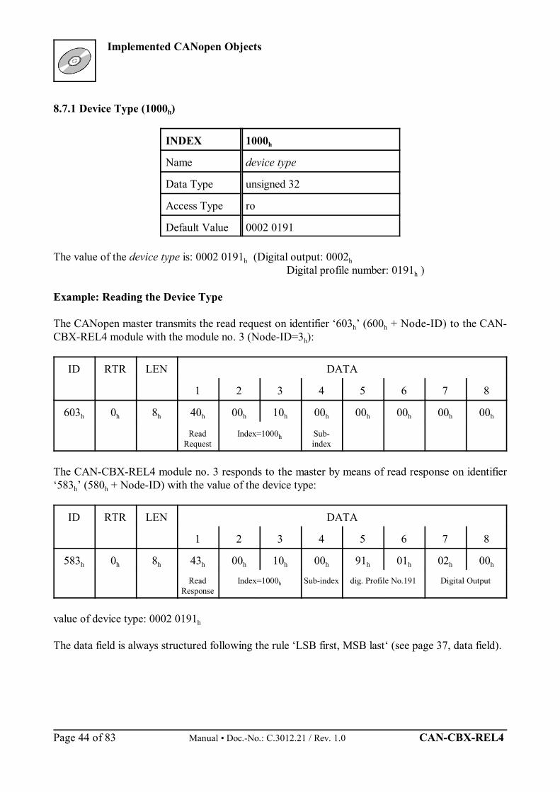
8.7.1 Device Type (1000h)
INDEX 1000h
Name device type
Data Type unsigned 32
Access Type ro
Default Value 0002 0191
The value of the device type is: 0002 0191h (Digital output: 0002hDigital profile number: 0191h )
Example: Reading the Device Type
The CANopen master transmits the read request on identifier ‘603h’ (600h + Node-ID) to the CAN-CBX-REL4 module with the module no. 3 (Node-ID=3h):
ID RTR LEN DATA
1 2 3 4 5 6 7 8
603h 0h 8h 40h 00h 10h 00h 00h 00h 00h 00h
ReadRequest
Index=1000h Sub-index
The CAN-CBX-REL4 module no. 3 responds to the master by means of read response on identifier‘583h’ (580h + Node-ID) with the value of the device type:
ID RTR LEN DATA
1 2 3 4 5 6 7 8
583h 0h 8h 43h 00h 10h 00h 91h 01h 02h 00h
ReadResponse
Index=1000h Sub-index dig. Profile No.191 Digital Output
value of device type: 0002 0191h
The data field is always structured following the rule ‘LSB first, MSB last‘ (see page 37, data field).
Implemented CANopen Objects
CAN-CBX-REL4 Manual • Doc.-No.: C.3012.21 / Rev. 1.0 Page 45 of 83
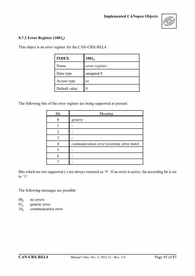
8.7.2 Error Register (1001h)
This object is an error register for the CAN-CBX-REL4.
INDEX 1001h
Name error register
Data type unsigned 8
Access type ro
Default value 0
The following bits of the error register are being supported at present:
Bit Meaning0 generic1 -2 -3 -4 communication error (overrun, error state)5 -6 -7 -
Bits which are not supported (-) are always returned as ‘0’. If an error is active, the according bit is setto ‘1’.
The following messages are possible:
00h no errors01h generic error10h communication error
Implemented CANopen Objects
Manual • Doc.-No.: C.3012.21 / Rev. 1.0 CAN-CBX-REL4 Page 46 of 83
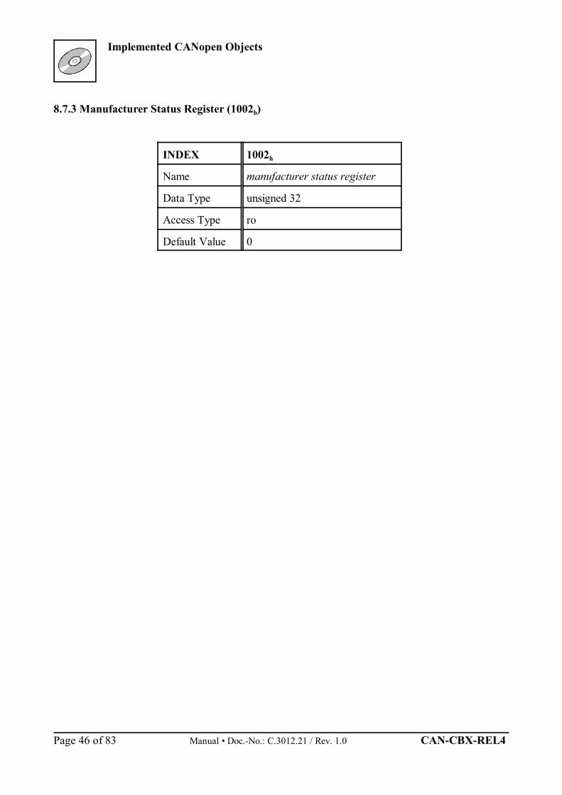
8.7.3 Manufacturer Status Register (1002h)
INDEX 1002h
Name manufacturer status register
Data Type unsigned 32
Access Type ro
Default Value 0

Implemented CANopen Objects
CAN-CBX-REL4 Manual • Doc.-No.: C.3012.21 / Rev. 1.0 Page 47 of 83
8.7.4 Pre-defined Error Field (1003h)
INDEX 1003h
Name pre-defined error field
Data type unsigned 32
Access type ro
Default value No
The pre-defined error field provides an error history of the errors that have occurred on the device andhave been signalled via the Emergency Object. Sub-index 0 contains the current number of errors stored in the list. Under sub-index 1 the last error which occurred is stored. If a new error occurs, the previous error isstored under sub-index 2 and the new error under sub-index 1, etc. In this way a list of the error historyis created.The error buffer is structured like a ring buffer. If it is full, the oldest entry is deleted for the latest entry.
This module supports a maximum of 10 error entries. When the 11th error occurs the oldest error entryis deleted. In order to delete the entire error list, sub-index ‘0’ has to be set to ‘0’. This is the onlypermissible write access to the object.
With every new entry to the list the module transmits an Emergency Frame to report the error.
Index[Hex]
Sub-index[Dec] Description Value range
[Hex] Default Data type R/W
1003
0 no_of_errors_in_list 0, 1...10 - unsigned 8 rw
1 error-code n 0...FFFF FFFF - unsigned 32 ro
2 error-code (n-1) 0...FFFF FFFF - unsigned 32 ro
: : : : : :
10 error-code (n-9) 0...FFFF FFFF - unsigned 32 ro
Meaning of the variables:
no_of_errors_in_list - contains the number of error codes currently on the listn = number of error which occurred last
- in order to delete the error list this variable has to be set to ‘0’- if no_of_errors_in_list 0, the error register (Object 1001h) is set
Implemented CANopen Objects
Manual • Doc.-No.: C.3012.21 / Rev. 1.0 CAN-CBX-REL4 Page 48 of 83
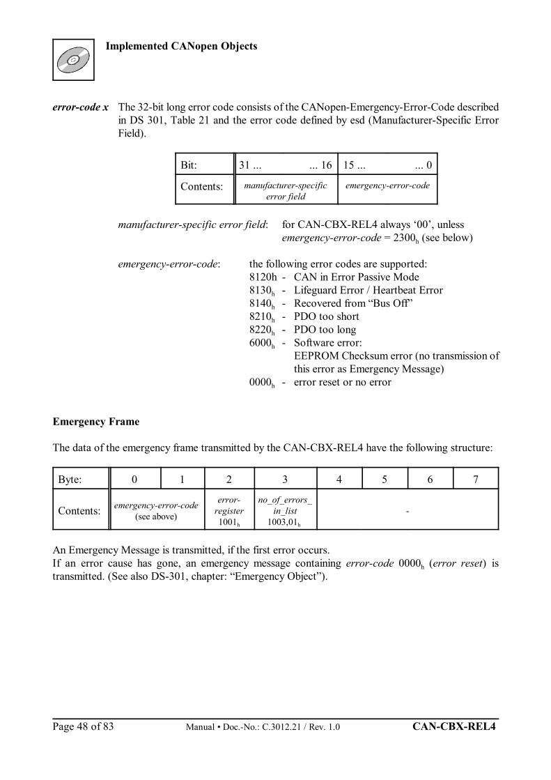
error-code x The 32-bit long error code consists of the CANopen-Emergency-Error-Code describedin DS 301, Table 21 and the error code defined by esd (Manufacturer-Specific ErrorField).
Bit: 31 ... ... 16 15 ... ... 0
Contents: manufacturer-specificerror field
emergency-error-code
manufacturer-specific error field: for CAN-CBX-REL4 always ‘00’, unlessemergency-error-code = 2300h (see below)
emergency-error-code: the following error codes are supported:8120h - CAN in Error Passive Mode8130h - Lifeguard Error / Heartbeat Error8140h - Recovered from “Bus Off”8210h - PDO too short8220h - PDO too long6000h - Software error:
EEPROM Checksum error (no transmission ofthis error as Emergency Message)
0000h - error reset or no error
Emergency Frame
The data of the emergency frame transmitted by the CAN-CBX-REL4 have the following structure:
Byte: 0 1 2 3 4 5 6 7
Contents: emergency-error-code(see above)
error-register1001h
no_of_errors_in_list
1003,01h -
An Emergency Message is transmitted, if the first error occurs.If an error cause has gone, an emergency message containing error-code 0000h (error reset) istransmitted. (See also DS-301, chapter: “Emergency Object”).
Implemented CANopen Objects
CAN-CBX-REL4 Manual • Doc.-No.: C.3012.21 / Rev. 1.0 Page 49 of 83
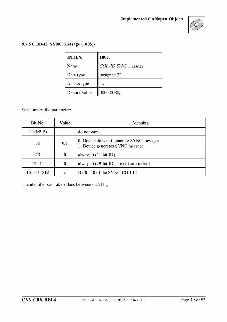
8.7.5 COB-ID SYNC Message (1005h)
INDEX 1005h
Name COB-ID SYNC message
Data type unsigned 32
Access type rw
Default value 0000 0080h
Structure of the parameter:
Bit-No. Value Meaning
31 (MSB) - do not care
30 0/1 0: Device does not generate SYNC message1: Device generates SYNC message
29 0 always 0 (11-bit ID)
28...11 0 always 0 (29-bit IDs are not supported)
10...0 (LSB) x Bit 0...10 of the SYNC-COB-ID
The identifier can take values between 0...7FFh.

Implemented CANopen Objects
Manual • Doc.-No.: C.3012.21 / Rev. 1.0 CAN-CBX-REL4 Page 50 of 83
8.7.6 Manufacturer’s Device Name (1008h)
INDEX 1008h
Name manufacturer’s device name
Data type visible string
Default value string: ‘CAN-CBX-REL4’
For detailed description of the Domain Uploads, please refer to CiA DS 202-2 (CMS-ProtocolSpecification).
Implemented CANopen Objects
CAN-CBX-REL4 Manual • Doc.-No.: C.3012.21 / Rev. 1.0 Page 51 of 83
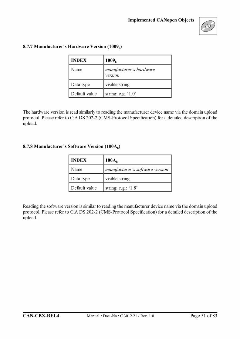
8.7.7 Manufacturer’s Hardware Version (1009h)
INDEX 1009h
Name manufacturer’s hardwareversion
Data type visible string
Default value string: e.g. ‘1.0’
The hardware version is read similarly to reading the manufacturer device name via the domain uploadprotocol. Please refer to CiA DS 202-2 (CMS-Protocol Specification) for a detailed description of theupload.
8.7.8 Manufacturer’s Software Version (100Ah)
INDEX 100Ah
Name manufacturer’s software version
Data type visible string
Default value string: e.g.: ‘1.8’
Reading the software version is similar to reading the manufacturer device name via the domain uploadprotocol. Please refer to CiA DS 202-2 (CMS-Protocol Specification) for a detailed description of theupload.
Implemented CANopen Objects
Manual • Doc.-No.: C.3012.21 / Rev. 1.0 CAN-CBX-REL4 Page 52 of 83
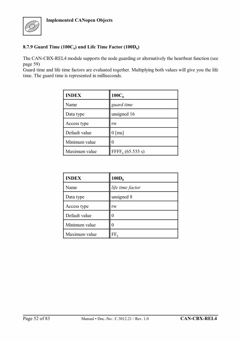
8.7.9 Guard Time (100Ch) und Life Time Factor (100Dh)
The CAN-CBX-REL4 module supports the node guarding or alternatively the heartbeat function (seepage 59)Guard time and life time factors are evaluated together. Multiplying both values will give you the lifetime. The guard time is represented in milliseconds.
INDEX 100Ch
Name guard time
Data type unsigned 16
Access type rw
Default value 0 [ms]
Minimum value 0
Maximum value FFFFh (65.535 s)
INDEX 100Dh
Name life time factor
Data type unsigned 8
Access type rw
Default value 0
Minimum value 0
Maximum value FFh
Implemented CANopen Objects
CAN-CBX-REL4 Manual • Doc.-No.: C.3012.21 / Rev. 1.0 Page 53 of 83
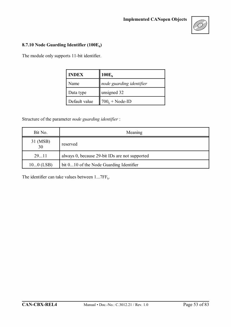
8.7.10 Node Guarding Identifier (100Eh)
The module only supports 11-bit identifier.
INDEX 100Eh
Name node guarding identifier
Data type unsigned 32
Default value 700h + Node-ID
Structure of the parameter node guarding identifier :
Bit No. Meaning
31 (MSB)30 reserved
29...11 always 0, because 29-bit IDs are not supported
10...0 (LSB) bit 0...10 of the Node Guarding Identifier
The identifier can take values between 1...7FFh.
Implemented CANopen Objects
Manual • Doc.-No.: C.3012.21 / Rev. 1.0 CAN-CBX-REL4 Page 54 of 83
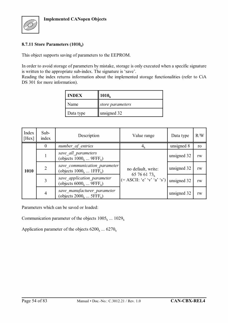
8.7.11 Store Parameters (1010h)
This object supports saving of parameters to the EEPROM.
In order to avoid storage of parameters by mistake, storage is only executed when a specific signatureis written to the appropriate sub-index. The signature is ‘save’.Reading the index returns information about the implemented storage functionalities (refer to CiADS 301 for more information).
INDEX 1010h
Name store parameters
Data type unsigned 32
Index[Hex]
Sub-index Description Value range Data type R/W
1010
0 number_of_entries 4h unsigned 8 ro
1 save_all_parameters(objects 1000h ... 9FFFh)
no default, write: 65 76 61 73h
(= ASCII: ‘e’ ‘v’ ‘a’ ‘s’)
unsigned 32 rw
2 save_communication_parameter(objects 1000h ... 1FFFh)
unsigned 32 rw
3 save_application_parameter(objects 6000h ... 9FFFh)
unsigned 32 rw
4 save_manufacturer_parameter(objects 2000h ... 5FFFh)
unsigned 32 rw
Parameters which can be saved or loaded:
Communication parameter of the objects 1005h ... 1029h
Application parameter of the objects 6200h ... 6270h
Implemented CANopen Objects
CAN-CBX-REL4 Manual • Doc.-No.: C.3012.21 / Rev. 1.0 Page 55 of 83
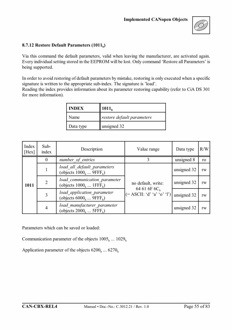
8.7.12 Restore Default Parameters (1011h)
Via this command the default parameters, valid when leaving the manufacturer, are activated again.Every individual setting stored in the EEPROM will be lost. Only command ‘Restore all Parameters’ isbeing supported.
In order to avoid restoring of default parameters by mistake, restoring is only executed when a specificsignature is written to the appropriate sub-index. The signature is ’load’.Reading the index provides information about its parameter restoring capability (refer to CiA DS 301for more information).
INDEX 1011h
Name restore default parameters
Data type unsigned 32
Index[Hex]
Sub-index Description Value range Data type R/W
1011
0 number_of_entries 3 unsigned 8 ro
1 load_all_default_parameters(objects 1000h ... 9FFFh)
no default, write: 64 61 6F 6Ch
(= ASCII: ‘d’ ‘a’ ‘o’ ‘l’)
unsigned 32 rw
2 load_communication_parameter(objects 1000h ... 1FFFh)
unsigned 32 rw
3 load_application_parameter(objects 6000h ... 9FFFh)
unsigned 32 rw
4 load_manufacturer_parameter(objects 2000h ... 5FFFh)
unsigned 32 rw
Parameters which can be saved or loaded:
Communication parameter of the objects 1005h ... 1029h
Application parameter of the objects 6200h ... 6270h
Implemented CANopen Objects
Manual • Doc.-No.: C.3012.21 / Rev. 1.0 CAN-CBX-REL4 Page 56 of 83
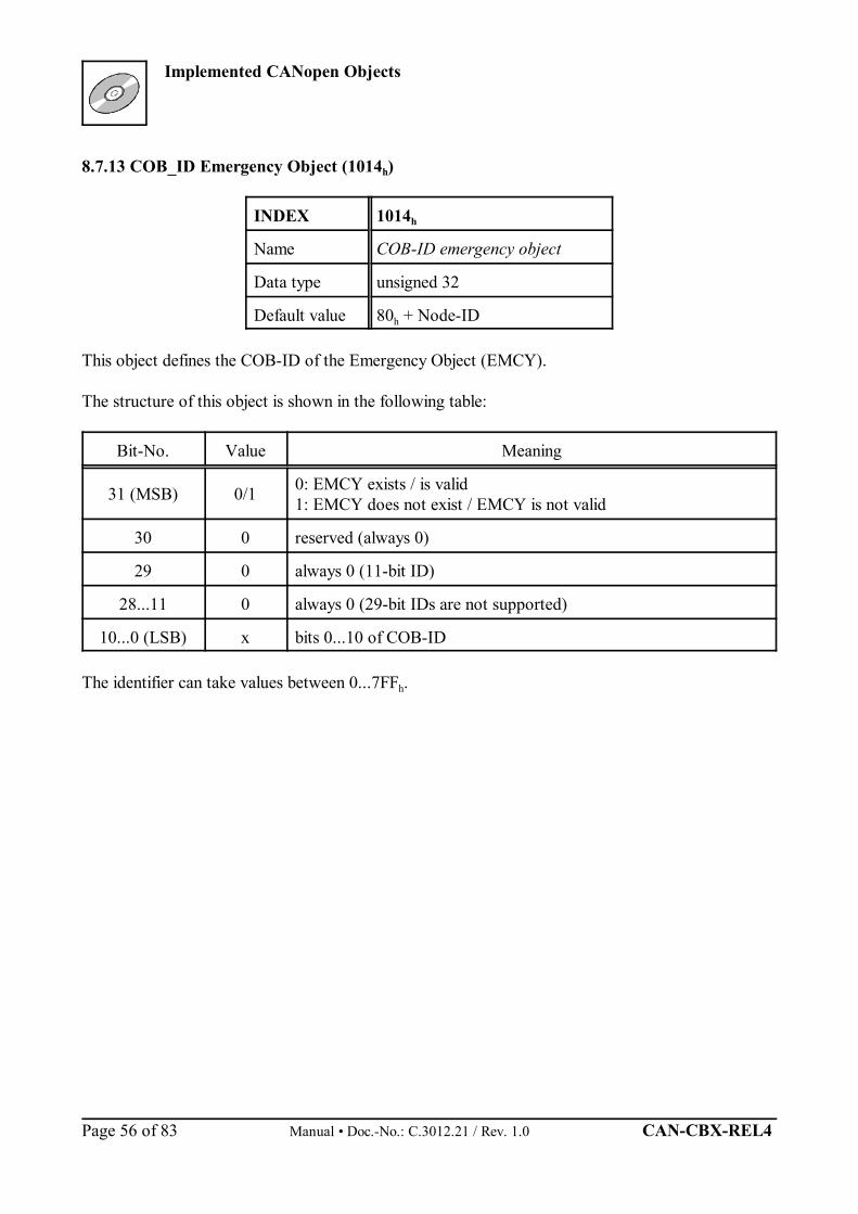
8.7.13 COB_ID Emergency Object (1014h)
INDEX 1014h
Name COB-ID emergency object
Data type unsigned 32
Default value 80h + Node-ID
This object defines the COB-ID of the Emergency Object (EMCY).
The structure of this object is shown in the following table:
Bit-No. Value Meaning
31 (MSB) 0/1 0: EMCY exists / is valid1: EMCY does not exist / EMCY is not valid
30 0 reserved (always 0)
29 0 always 0 (11-bit ID)
28...11 0 always 0 (29-bit IDs are not supported)
10...0 (LSB) x bits 0...10 of COB-ID
The identifier can take values between 0...7FFh.
Implemented CANopen Objects
CAN-CBX-REL4 Manual • Doc.-No.: C.3012.21 / Rev. 1.0 Page 57 of 83
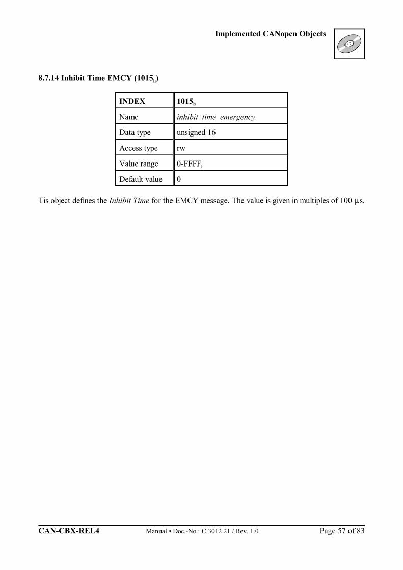
8.7.14 Inhibit Time EMCY (1015h)
INDEX 1015h
Name inhibit_time_emergency
Data type unsigned 16
Access type rw
Value range 0-FFFFh
Default value 0
Tis object defines the Inhibit Time for the EMCY message. The value is given in multiples of 100 s.

Implemented CANopen Objects
Manual • Doc.-No.: C.3012.21 / Rev. 1.0 CAN-CBX-REL4 Page 58 of 83
8.7.15 Consumer Heartbeat Time (1016h)
INDEX 1016h
Name consumer heartbeat time
Data type unsigned 32
Default value No
The heartbeat function can be used for mutual monitoring of the CANopen modules (especially to detectconnection failures). The heartbeat function does not require RTR-Frames.
Function:A module, the so-called heartbeat producer, cyclically transmits a heartbeat message on the CAN-buson the node-guarding identifier (see object 100Eh). One or more heartbeat consumer receive themessage. It has to be received within the heartbeat time stored on the heartbeat consumer, otherwise aheartbeat event is triggered on the heartbeat-consumer module. A heartbeat event generates a heartbeaterror on the CAN-CBX-REL4 module.
Each module can act as a heartbeat producer and a heartbeat consumer. One CAN-network can containseveral heartbeat producers and heartbeat consumers.
Index[Hex] Sub-index Description Value range
[Hex] Default Data type Index[Hex]
10160 number_of_entries 1 1 unsigned 8 ro
1 consumer-heartbeat_time 0...007FFFFF 0 unsigned 32 rw
Meaning of the Variable consumer-heartbeat_time_x:consumer-heartbeat_time_x
Bit 31 ... ...24 23 ... ...16 15 ... ...0
Assignment reserved(always ‘0’)
Node-ID (unsigned 8)
heartbeat_time(unsigned 16)
Node-ID Node-Id of the heartbeat producer to be monitored.
heartbeat_time Cycle time of heartbeat producer to transmit the heartbeat on the node-guardingID (see object 100Eh).The consumer-heartbeat time of the monitoring module must always be higherthan the producer-heartbeat time of the heartbeat-transmitting module.

Implemented CANopen Objects
CAN-CBX-REL4 Manual • Doc.-No.: C.3012.21 / Rev. 1.0 Page 59 of 83
8.7.16 Producer Heartbeat Time (1017h)
INDEX 1017h
Name producer heartbeat time
Data type unsigned 16
Default value 0 ms
The Producer Heartbeat time defines the cycle time with which the CAN-CBX-REL4 module transmitsa heartbeat-frame to the node-guarding ID.
If the value of the producer heartbeat time is higher than ‘0’, it is active and stops the Node-/ Life-Guarding (see page 52). If the value of the producer-heartbeat-time is set to ‘0’, transmitting heartbeats by this module isstopped.
Index[Hex] Sub-index Description Value range
[Hex] Default Data type R/W
1017 0 producer-heartbeat_time 0...FFFF 0 ms unsigned 16 rw
producer-heartbeat_time Cycle time of heartbeat producer to transmit the heartbeat on the node-guarding ID (see object 100Eh).The consumer-heartbeat time of the monitoring module must always behigher than the producer-heartbeat time of the heartbeat-transmittingmodule.
Implemented CANopen Objects
Manual • Doc.-No.: C.3012.21 / Rev. 1.0 CAN-CBX-REL4 Page 60 of 83
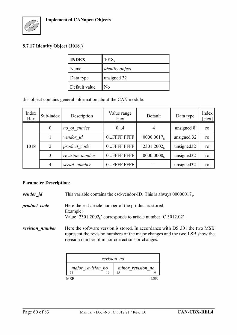
8.7.17 Identity Object (1018h)
INDEX 1018h
Name identity object
Data type unsigned 32
Default value No
this object contains general information about the CAN module.
Index[Hex] Sub-index Description Value range
[Hex] Default Data type Index[Hex]
1018
0 no_of_entries 0...4 4 unsigned 8 ro
1 vendor_id 0...FFFF FFFF 0000 0017h unsigned 32 ro
2 product_code 0...FFFF FFFF 2301 2002h unsigned32 ro
3 revision_number 0...FFFF FFFF 0000 0000h unsigned32 ro
4 serial_number 0...FFFF FFFF - unsigned32 ro
Parameter Description:
vendor_id This variable contains the esd-vendor-ID. This is always 00000017h.
product_code Here the esd-article number of the product is stored.Example: Value ‘2301 2002h’ corresponds to article number ‘C.3012.02’.
revision_number Here the software version is stored. In accordance with DS 301 the two MSBrepresent the revision numbers of the major changes and the two LSB show therevision number of minor corrections or changes.
revision_no
major_revision_no31 16
minor_revision_no15 0
MSB LSB
Implemented CANopen Objects
CAN-CBX-REL4 Manual • Doc.-No.: C.3012.21 / Rev. 1.0 Page 61 of 83
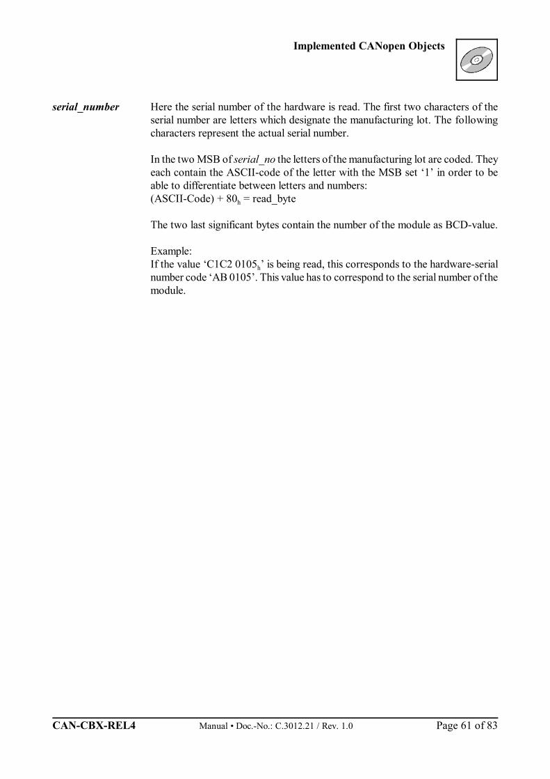
serial_number Here the serial number of the hardware is read. The first two characters of theserial number are letters which designate the manufacturing lot. The followingcharacters represent the actual serial number.
In the two MSB of serial_no the letters of the manufacturing lot are coded. Theyeach contain the ASCII-code of the letter with the MSB set ‘1’ in order to beable to differentiate between letters and numbers:(ASCII-Code) + 80h = read_byte
The two last significant bytes contain the number of the module as BCD-value.
Example:If the value ‘C1C2 0105h’ is being read, this corresponds to the hardware-serialnumber code ‘AB 0105’. This value has to correspond to the serial number of themodule.
Implemented CANopen Objects
Manual • Doc.-No.: C.3012.21 / Rev. 1.0 CAN-CBX-REL4 Page 62 of 83
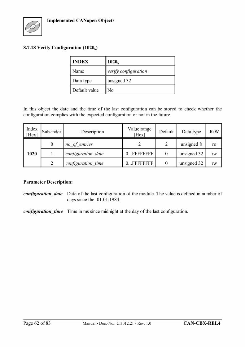
8.7.18 Verify Configuration (1020h)
INDEX 1020h
Name verify configuration
Data type unsigned 32
Default value No
In this object the date and the time of the last configuration can be stored to check whether theconfiguration complies with the expected configuration or not in the future.
Index[Hex] Sub-index Description Value range
[Hex] Default Data type R/W
1020
0 no_of_entries 2 2 unsigned 8 ro
1 configuration_date 0...FFFFFFFF 0 unsigned 32 rw
2 configuration_time 0...FFFFFFFF 0 unsigned 32 rw
Parameter Description:
configuration_date Date of the last configuration of the module. The value is defined in number ofdays since the 01.01.1984.
configuration_time Time in ms since midnight at the day of the last configuration.
Implemented CANopen Objects
CAN-CBX-REL4 Manual • Doc.-No.: C.3012.21 / Rev. 1.0 Page 63 of 83
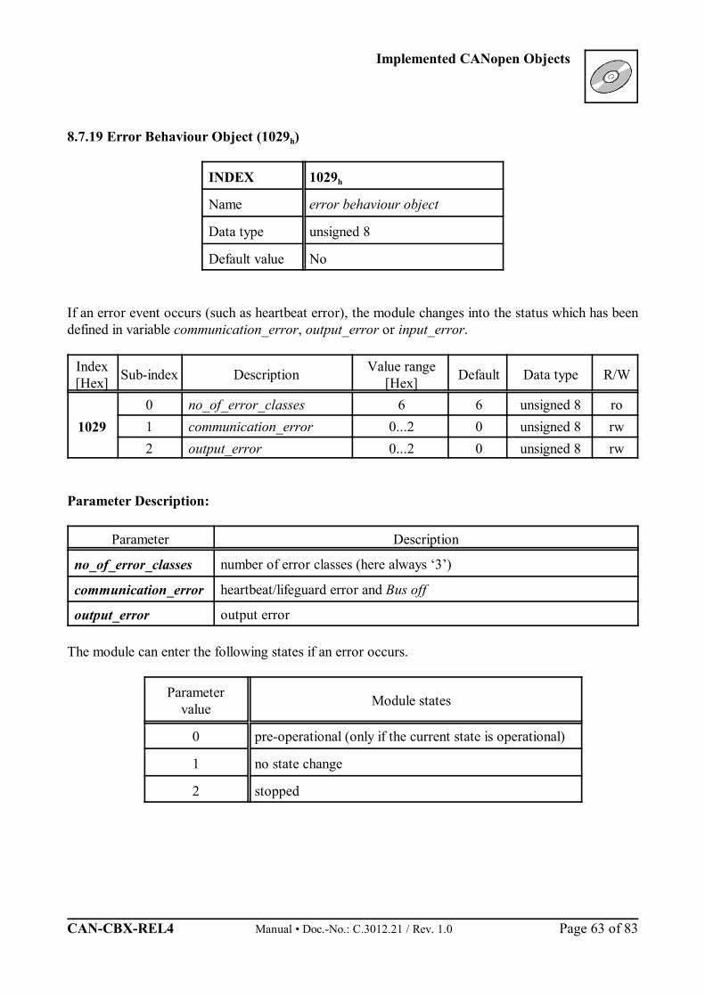
8.7.19 Error Behaviour Object (1029h)
INDEX 1029h
Name error behaviour object
Data type unsigned 8
Default value No
If an error event occurs (such as heartbeat error), the module changes into the status which has beendefined in variable communication_error, output_error or input_error.
Index[Hex] Sub-index Description Value range
[Hex] Default Data type R/W
10290 no_of_error_classes 6 6 unsigned 8 ro1 communication_error 0...2 0 unsigned 8 rw2 output_error 0...2 0 unsigned 8 rw
Parameter Description:
Parameter Description
no_of_error_classes number of error classes (here always ‘3’)
communication_error heartbeat/lifeguard error and Bus off
output_error output error
The module can enter the following states if an error occurs.
Parametervalue Module states
0 pre-operational (only if the current state is operational)
1 no state change
2 stopped
Implemented CANopen Objects
Manual • Doc.-No.: C.3012.21 / Rev. 1.0 CAN-CBX-REL4 Page 64 of 83
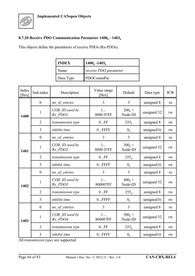
8.7.20 Receive PDO Communication Parameter 1400h - 1403h
This objects define the parameters of receive PDOs (Rx-PDOs).
INDEX 1400h -1403h
Name receive PDO parameter
Data Type PDOCommPar
Index[Hex] Sub-index Description Value range
[Hex] Default Data type R/W
1400
0 no_of_entries 3 3 unsigned 8 ro
1 COB_ID used byRx_PDO1
1...0000 07FF
200h +Node-ID unsigned 32 rw
2 transmission type 0...FF 255d unsigned 8 rw
3 inhibit time 0...FFFF 0h unsigned16 rw
1401
0 no_of_entries 3 3 unsigned 8 ro
1 COB_ID used byRx_PDO2
1...8000 07FF
300h +Node-ID unsigned 32 rw
2 transmission type 0...FF 255d unsigned 8 rw
3 inhibit time 0...FFFF 0h unsigned16 rw
1402
0 no_of_entries 3 3 unsigned 8 ro
1 COB_ID used byRx_PDO3
1...800007FF
400h +Node-ID unsigned 32 rw
2 transmission type 0...FF 255d unsigned 8 rw
3 inhibit time 0...FFFF 0h unsigned16 rw
1403
0 no_of_entries 3 3 unsigned 8 ro
1 COB_ID used byRx_PDO4
1...800007FF
500h +Node-ID unsigned 32 rw
2 transmission type 0...FF 255d unsigned 8 rw
3 inhibit time 0...FFFF 0h unsigned16 rwAll transmission types are supported.
Implemented CANopen Objects
CAN-CBX-REL4 Manual • Doc.-No.: C.3012.21 / Rev. 1.0 Page 65 of 83
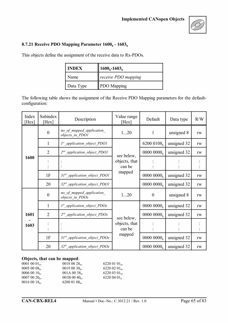
8.7.21 Receive PDO Mapping Parameter 1600h - 1603h
This objects define the assignment of the receive data to Rx-PDOs.
INDEX 1600h-1603h
Name receive PDO mapping
Data Type PDO Mapping
The following table shows the assignment of the Receive PDO Mapping parameters for the default-configuration:
Index[Hex]
Subindex[Hex] Description Value range
[Hex] Default Data type R/W
1600
0 no_of_mapped_application_objects_in_PDO1 1...20 1 unsigned 8 rw
1 1st_application_object_PDO1
see below,objects, that
can bemapped
6200 0108h unsigned 32 rw
2 2nd_application_object_PDO1 0000 0000h unsigned 32 rw
::
::
::
::
::
1F 31th_application_object_PDO1 0000 0000h unsigned 32 rw
20 32th_application_object_PDO1 0000 0000h unsigned 32 rw
1601-
1603
0 no_of_mapped_application_objects_in_PDOx 1...20 0 unsigned 8 rw
1 1st_application_object_PDOx
see below,objects, that
can bemapped
0000 0000h unsigned 32 rw
2 2nd_application_object_PDOx 0000 0000h unsigned 32 rw
::
::
::
::
::
1F 31th_application_object_PDOx 0000 0000h unsigned 32 rw
20 32th_application_object_PDOx 0000 0000h unsigned 32 rw
Objects, that can be mapped:0001 00 01h, 0018 00 28h, 6220 01 01h,0005 00 08h, 0019 00 30h, 6220 02 01h,0006 00 10h, 001A 00 38h, 6220 03 01h,0007 00 20h, 001B 00 40h, 6220 04 01h
0016 00 18h, 6200 01 08h,
Implemented CANopen Objects
Manual • Doc.-No.: C.3012.21 / Rev. 1.0 CAN-CBX-REL4 Page 66 of 83
i
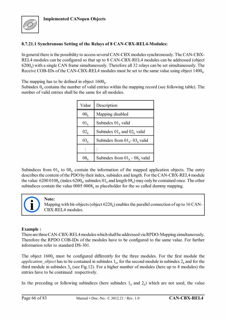
8.7.21.1 Synchronous Setting of the Relays of 8 CAN-CBX-REL4-Modules:
In general there is the possibility to access several CAN-CBX modules synchronously. The CAN-CBX-REL4 modules can be configured so that up to 8 CAN-CBX-REL4 modules can be addressed (object6200h) with a single CAN frame simultaneously. Therefore all 32 relays can be set simultaneously. TheReceive COB-IDs of the CAN-CBX-REL4 modules must be set to the same value using object 1400h.
The mapping has to be defined in object 1600h. Subindex 0h contains the number of valid entries within the mapping record (see following table). Thenumber of valid entries shall be the same for all modules.
Value Description
00h Mapping disabled
01h Subindex 01h valid
02h Subindex 01h and 02h valid
03h Subindex from 01h- 03h valid
: :
08h Subindex from 01h - 08h valid
Subindices from 01h to 08h contain the information of the mapped application objects. The entrydescribes the content of the PDO by their index, subindex and length. For the CAN-CBX-REL4 modulethe value 6200 0108h (index 6200h, subindex 01h and length 08h) may only be contained once. The othersubindices contain the value 0005 0008h as placeholder for the so called dummy mapping.
Note:Mapping with bit-objects (object 6220h) enables the parallel connection of up to 16 CAN-CBX-REL4 modules.
Example :There are three CAN-CBX-REL4 modules which shall be addressed via RPDO-Mapping simultaneously.Therefore the RPDO COB-IDs of the modules have to be configured to the same value. For furtherinformation refer to standard DS-301.
The object 1600h must be configured differently for the three modules. For the first module theapplication_object has to be contained in subindex 1h, for the second module in subindex 2h and for thethird module in subindex 3h (see Fig.12). For a higher number of modules (here up to 8 modules) theentries have to be continued respectively.
In the preceding or following subindices (here subindex 1h and 2h) which are not used, the value
Implemented CANopen Objects
CAN-CBX-REL4 Manual • Doc.-No.: C.3012.21 / Rev. 1.0 Page 67 of 83
3
00050008
0h
1h
2h
62000108
3h
Objekt 1600h
00050008
62000108
3
62000108
0h
1h
2h
62000108
000500083h
Objekt 1600h
00050008
3
62000108
00050008
0h
1h
2h
62000108
000500083h
Objekt 1600h
COB-ID
Rx-PDO
Len = 31 32 4 5 6 7 8
Module 3Outputs
Module 2Outputs
Module 1Outputs
Data Bytes
COB-ID (Module 1) = COB-ID (Module 2) = COB-ID (Module 3)The COB-IDs of the modules must be set to the same value via object 1400h.
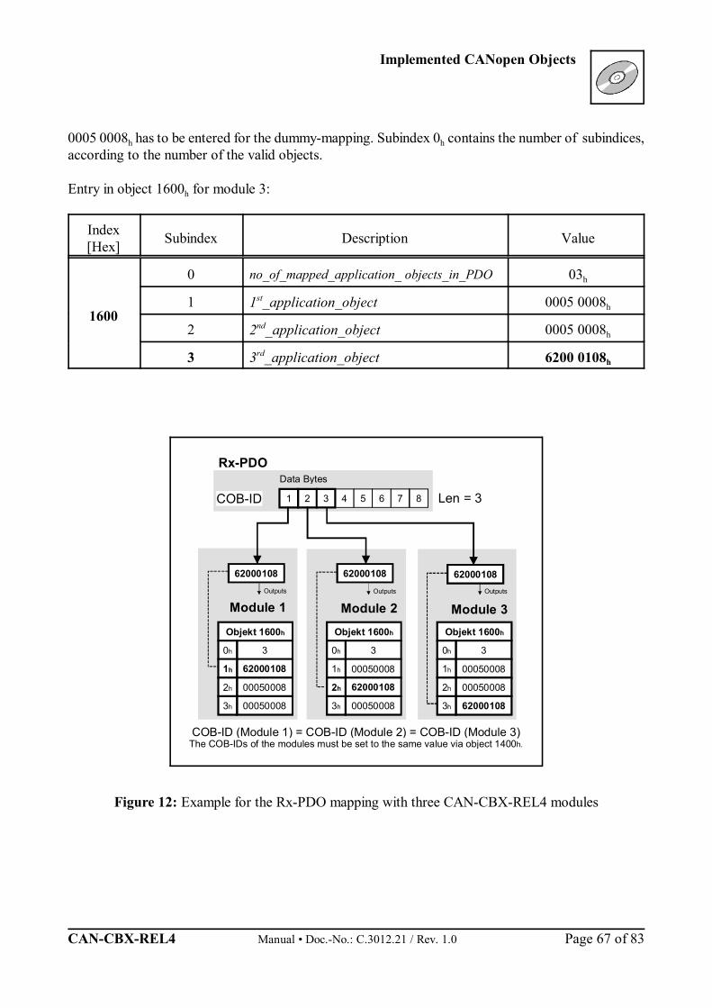
0005 0008h has to be entered for the dummy-mapping. Subindex 0h contains the number of subindices,according to the number of the valid objects.
Entry in object 1600h for module 3:
Index[Hex] Subindex Description Value
1600
0 no_of_mapped_application_ objects_in_PDO 03h
1 1st_application_object 0005 0008h
2 2nd_application_object 0005 0008h
3 3rd_application_object 6200 0108h
Figure 12: Example for the Rx-PDO mapping with three CAN-CBX-REL4 modules
Implemented CANopen Objects
Manual • Doc.-No.: C.3012.21 / Rev. 1.0 CAN-CBX-REL4 Page 68 of 83
80h
1h
2h
6220 0X 01
3h
Objekt 1600h
4h
5h
6h
7h
8h
Rx-PDO
1 32 4 5 6 7 8
6220 01 01
0001 00 01
0001 00 01
0001 00 01
0001 00 01
COB-ID(200+Node-ID)13 24567 0
Rel4
6220 02 01
6220 03 01
6220 04 01
Rel3 Rel2 Rel1
Relay x
Data byteData byte 1of Rx-PDO
Module 1Relay 1- 4
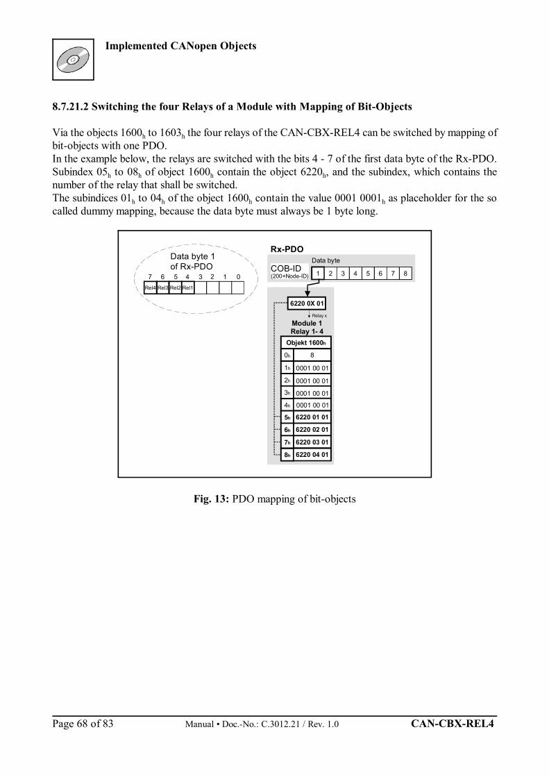
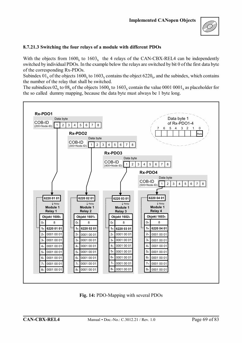
8.7.21.2 Switching the four Relays of a Module with Mapping of Bit-Objects
Via the objects 1600h to 1603h the four relays of the CAN-CBX-REL4 can be switched by mapping ofbit-objects with one PDO. In the example below, the relays are switched with the bits 4 - 7 of the first data byte of the Rx-PDO.Subindex 05h to 08h of object 1600h contain the object 6220h, and the subindex, which contains thenumber of the relay that shall be switched. The subindices 01h to 04h of the object 1600h contain the value 0001 0001h as placeholder for the socalled dummy mapping, because the data byte must always be 1 byte long.
Fig. 13: PDO mapping of bit-objects
Implemented CANopen Objects
CAN-CBX-REL4 Manual • Doc.-No.: C.3012.21 / Rev. 1.0 Page 69 of 83
80h
1h
2h
6220 03 01
3h
Objekt 1602h
80h
1h
2h
6220 02 01
3h
Objekt 1601h
8
6220 01 01
0001 00 01
0h
1h
2h
6220 01 01
0001 00 013h
Objekt 1600h
COB-ID(200+Node-ID)
Rx-PDO1
1 32 4 5 6 7 8
80h
1h
2h
6220 04 01
3h
Objekt 1603h
4h 0001 00 01 4h 4h 4h
0001 00 01
5h
6h
0001 00 017h
8h 0001 00 01
0001 00 01 5h
6h
7h
8h
5h
6h
7h
8h
5h
6h
7h
8h
Rx-PDO4
1 32 4 5 6 7 8
Rx-PDO3
1 32 4 5 6 7 8
Rx-PDO2
1 32 4 5 6 7 8
6220 02 01
0001 00 01
0001 00 01
0001 00 01
0001 00 01
0001 00 01
0001 00 01
0001 00 01
6220 03 01
0001 00 01
0001 00 01
0001 00 01
0001 00 01
0001 00 01
0001 00 01
0001 00 01
6220 04 01
0001 00 01
0001 00 01
0001 00 01
0001 00 01
0001 00 01
0001 00 01
0001 00 01
COB-ID(300+Node-ID)
COB-ID(400+Node-ID)
COB-ID(500+Node-ID)
13 24567 0
Relx
RelayRelayRelay
Data byte
Relay
Data byte
Data byte
Data byte 1of Rx-PDO1-4
Module 1Relay 1
Module 1Relay 2
Module 1Relay 3
Module 1Relay 4
Data byte
8.7.21.3 Switching the four relays of a module with different PDOs
With the objects from 1600h to 1603h the 4 relays of the CAN-CBX-REL4 can be independentlyswitched by individual PDOs. In the example below the relays are switched by bit 0 of the first data byteof the corresponding Rx-PDOs. Subindex 01h of the objects 1600h to 1603h contains the object 6220h, and the subindex, which containsthe number of the relay that shall be switched. The subindices 02h to 08h of the objects 1600h to 1603h contain the value 0001 0001h as placeholder forthe so called dummy mapping, because the data byte must always be 1 byte long.
Fig. 14: PDO-Mapping with several PDOs
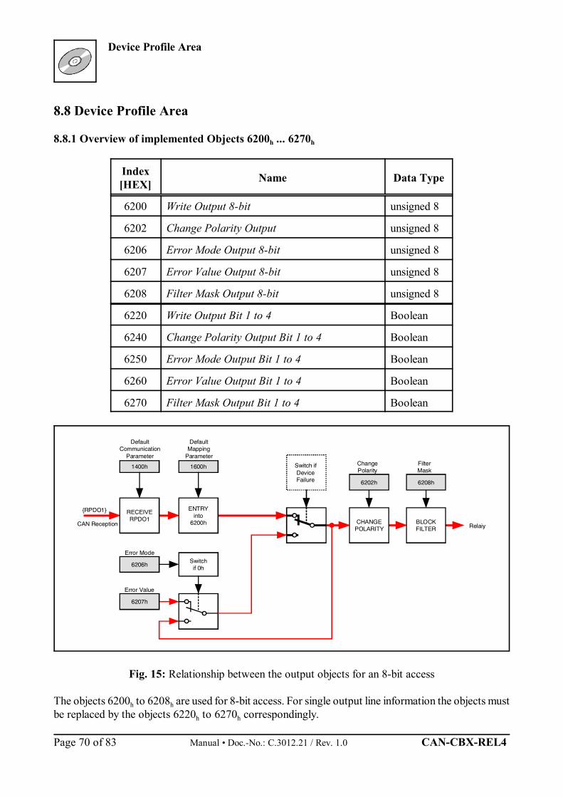
Device Profile Area
Manual • Doc.-No.: C.3012.21 / Rev. 1.0 CAN-CBX-REL4 Page 70 of 83
DefaultCommunication
Parameter
DefaultMapping
Parameter
1400h 1600h
RECEIVERPDO1
{RPDO1}
CAN Reception
ENTRYinto
6200h
Switchif 0h6206h
Error Mode
6207h
Error Value
Switch if Device Failure
CHANGEPOLARITY
ChangePolarity
6202h
Relaiy
FilterMask
6208h
BLOCKFILTER
8.8 Device Profile Area
8.8.1 Overview of implemented Objects 6200h ... 6270h
Index[HEX] Name Data Type
6200 Write Output 8-bit unsigned 8
6202 Change Polarity Output unsigned 8
6206 Error Mode Output 8-bit unsigned 8
6207 Error Value Output 8-bit unsigned 8
6208 Filter Mask Output 8-bit unsigned 8
6220 Write Output Bit 1 to 4 Boolean
6240 Change Polarity Output Bit 1 to 4 Boolean
6250 Error Mode Output Bit 1 to 4 Boolean
6260 Error Value Output Bit 1 to 4 Boolean
6270 Filter Mask Output Bit 1 to 4 Boolean
Fig. 15: Relationship between the output objects for an 8-bit access
The objects 6200h to 6208h are used for 8-bit access. For single output line information the objects mustbe replaced by the objects 6220h to 6270h correspondingly.
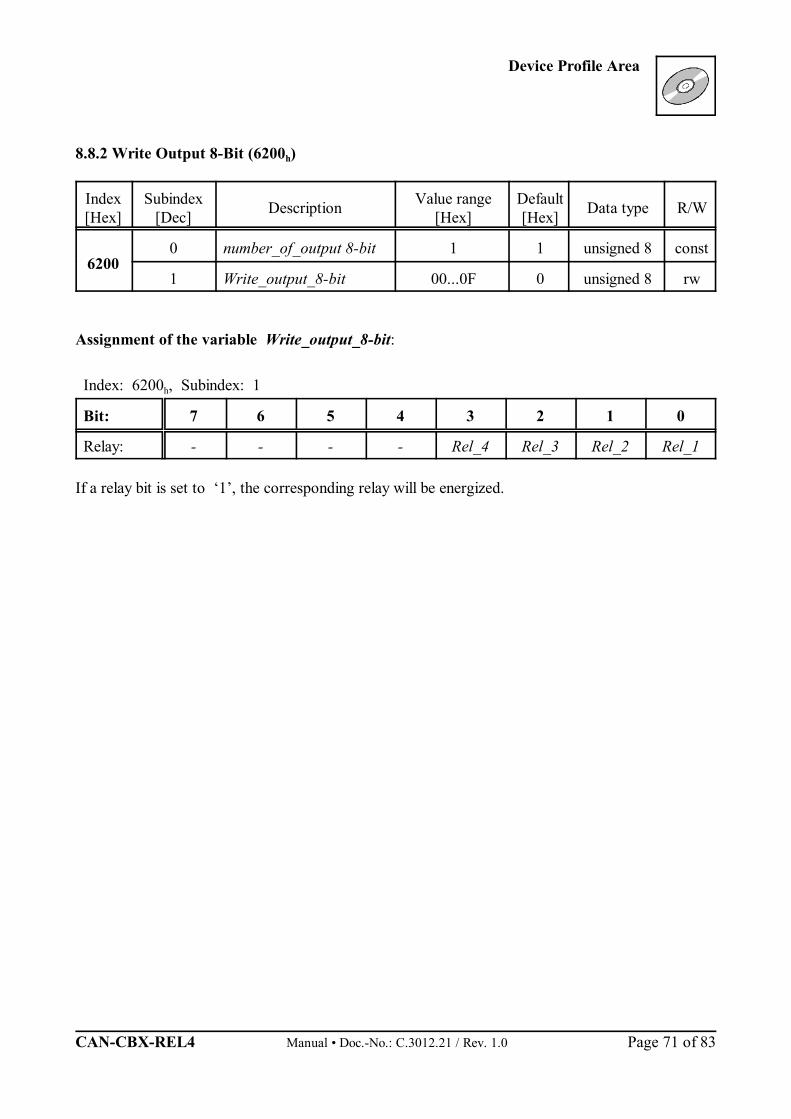
Device Profile Area
CAN-CBX-REL4 Manual • Doc.-No.: C.3012.21 / Rev. 1.0 Page 71 of 83
8.8.2 Write Output 8-Bit (6200h)
Index[Hex]
Subindex[Dec] Description Value range
[Hex]Default[Hex] Data type R/W
62000 number_of_output 8-bit 1 1 unsigned 8 const
1 Write_output_8-bit 00...0F 0 unsigned 8 rw
Assignment of the variable Write_output_8-bit:
Index: 6200h, Subindex: 1
Bit: 7 6 5 4 3 2 1 0
Relay: - - - - Rel_4 Rel_3 Rel_2 Rel_1
If a relay bit is set to ‘1’, the corresponding relay will be energized.
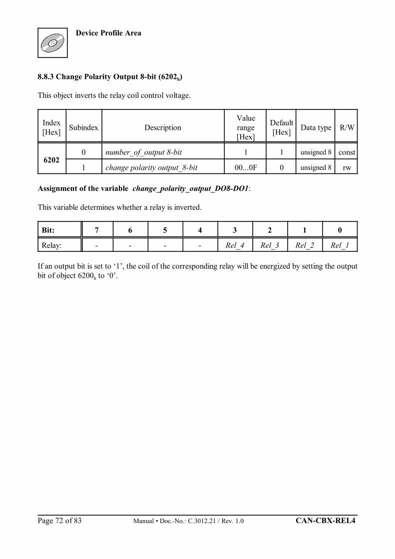
Device Profile Area
Manual • Doc.-No.: C.3012.21 / Rev. 1.0 CAN-CBX-REL4 Page 72 of 83
8.8.3 Change Polarity Output 8-bit (6202h)
This object inverts the relay coil control voltage.
Index[Hex] Subindex Description
Valuerange[Hex]
Default[Hex] Data type R/W
62020 number_of_output 8-bit 1 1 unsigned 8 const
1 change polarity output_8-bit 00...0F 0 unsigned 8 rw
Assignment of the variable change_polarity_output_DO8-DO1:
This variable determines whether a relay is inverted.
Bit: 7 6 5 4 3 2 1 0
Relay: - - - - Rel_4 Rel_3 Rel_2 Rel_1
If an output bit is set to ‘1’, the coil of the corresponding relay will be energized by setting the outputbit of object 6200h to ‘0’.
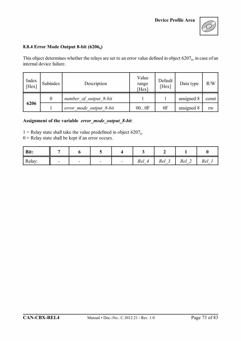
Device Profile Area
CAN-CBX-REL4 Manual • Doc.-No.: C.3012.21 / Rev. 1.0 Page 73 of 83
8.8.4 Error Mode Output 8-bit (6206h)
This object determines whether the relays are set to an error value defined in object 6207h, in case of aninternal device failure.
Index[Hex] Subindex Description
Valuerange[Hex]
Default[Hex] Data type R/W
62060 number_of_output_8-bit 1 1 unsigned 8 const
1 error_mode_output_8-bit 00...0F 0F unsigned 8 rw
Assignment of the variable error_mode_output_8-bit:
1 = Relay state shall take the value predefined in object 6207h. 0 = Relay state shall be kept if an error occurs.
Bit: 7 6 5 4 3 2 1 0
Relay: - - - - Rel_4 Rel_3 Rel_2 Rel_1
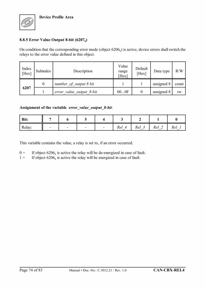
Device Profile Area
Manual • Doc.-No.: C.3012.21 / Rev. 1.0 CAN-CBX-REL4 Page 74 of 83
8.8.5 Error Value Output 8-bit (6207h)
On condition that the corresponding error mode (object 6206h) is active, device errors shall switch therelays to the error value defined in this object.
Index[Hex] Subindex Description
Valuerange[Hex]
Default[Hex] Data type R/W
62070 number_of_output 8 bit 1 1 unsigned 8 const
1 error_value_output_8-bit 00...0F 0 unsigned 8 rw
Assignment of the variable error_value_output_8-bit:
Bit: 7 6 5 4 3 2 1 0
Relay: - - - - Rel_4 Rel_3 Rel_2 Rel_1
This variable contains the value, a relay is set to, if an error occurred.
0 = If object 6206h is active the relay will be de-energized in case of fault.1 = If object 6206h is active the relay will be energized in case of fault.
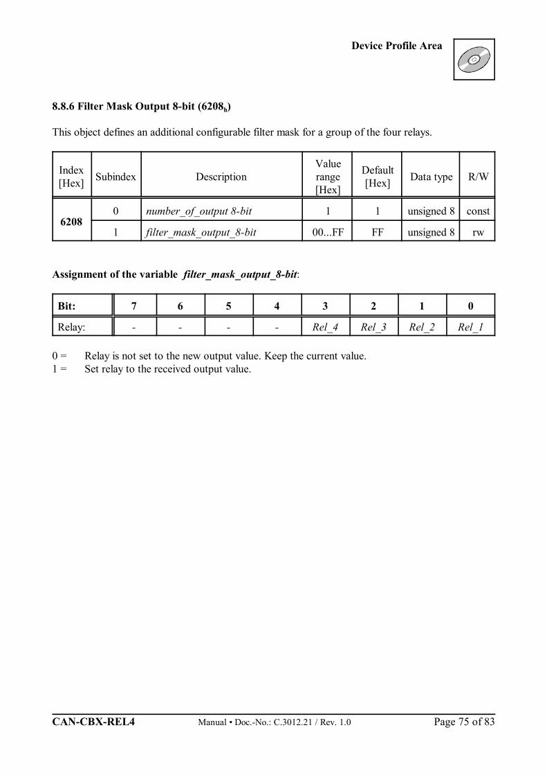
Device Profile Area
CAN-CBX-REL4 Manual • Doc.-No.: C.3012.21 / Rev. 1.0 Page 75 of 83
8.8.6 Filter Mask Output 8-bit (6208h)
This object defines an additional configurable filter mask for a group of the four relays.
Index[Hex] Subindex Description
Valuerange[Hex]
Default[Hex] Data type R/W
62080 number_of_output 8-bit 1 1 unsigned 8 const
1 filter_mask_output_8-bit 00...FF FF unsigned 8 rw
Assignment of the variable filter_mask_output_8-bit:
Bit: 7 6 5 4 3 2 1 0
Relay: - - - - Rel_4 Rel_3 Rel_2 Rel_1
0 = Relay is not set to the new output value. Keep the current value. 1 = Set relay to the received output value.
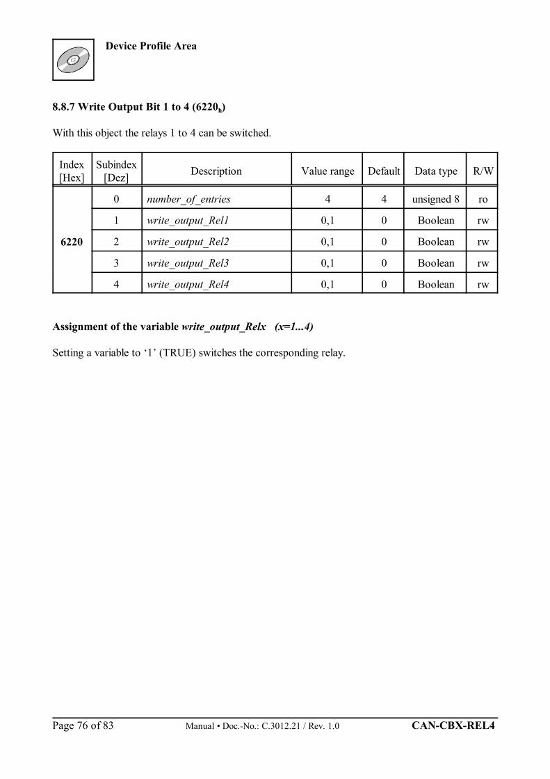
Device Profile Area
Manual • Doc.-No.: C.3012.21 / Rev. 1.0 CAN-CBX-REL4 Page 76 of 83
8.8.7 Write Output Bit 1 to 4 (6220h)
With this object the relays 1 to 4 can be switched.
Index[Hex]
Subindex[Dez] Description Value range Default Data type R/W
6220
0 number_of_entries 4 4 unsigned 8 ro
1 write_output_Rel1 0,1 0 Boolean rw
2 write_output_Rel2 0,1 0 Boolean rw
3 write_output_Rel3 0,1 0 Boolean rw
4 write_output_Rel4 0,1 0 Boolean rw
Assignment of the variable write_output_Relx (x=1...4)
Setting a variable to ‘1’ (TRUE) switches the corresponding relay.
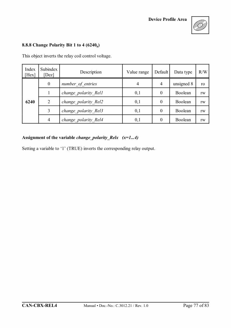
Device Profile Area
CAN-CBX-REL4 Manual • Doc.-No.: C.3012.21 / Rev. 1.0 Page 77 of 83
8.8.8 Change Polarity Bit 1 to 4 (6240h)
This object inverts the relay coil control voltage.
Index[Hex]
Subindex[Dez] Description Value range Default Data type R/W
6240
0 number_of_entries 4 4 unsigned 8 ro
1 change_polarity_Rel1 0,1 0 Boolean rw
2 change_polarity_Rel2 0,1 0 Boolean rw
3 change_polarity_Rel3 0,1 0 Boolean rw
4 change_polarity_Rel4 0,1 0 Boolean rw
Assignment of the variable change_polarity_Relx (x=1...4)
Setting a variable to ‘1’ (TRUE) inverts the corresponding relay output.
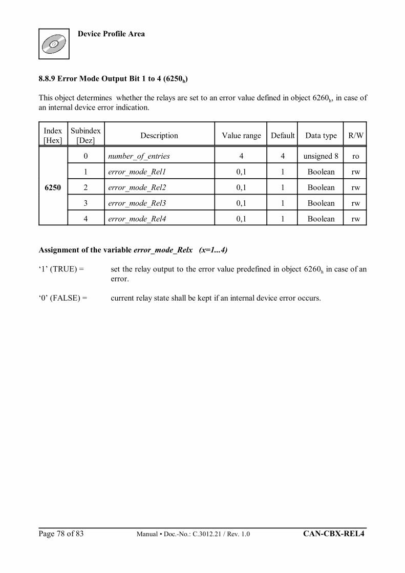
Device Profile Area
Manual • Doc.-No.: C.3012.21 / Rev. 1.0 CAN-CBX-REL4 Page 78 of 83
8.8.9 Error Mode Output Bit 1 to 4 (6250h)
This object determines whether the relays are set to an error value defined in object 6260h, in case ofan internal device error indication.
Index[Hex]
Subindex[Dez] Description Value range Default Data type R/W
6250
0 number_of_entries 4 4 unsigned 8 ro
1 error_mode_Rel1 0,1 1 Boolean rw
2 error_mode_Rel2 0,1 1 Boolean rw
3 error_mode_Rel3 0,1 1 Boolean rw
4 error_mode_Rel4 0,1 1 Boolean rw
Assignment of the variable error_mode_Relx (x=1...4)
‘1’ (TRUE) = set the relay output to the error value predefined in object 6260h in case of anerror.
‘0’ (FALSE) = current relay state shall be kept if an internal device error occurs.

Device Profile Area
CAN-CBX-REL4 Manual • Doc.-No.: C.3012.21 / Rev. 1.0 Page 79 of 83
8.8.10 Error Value Output Bit 1 to 4 (6260h)
On condition that the corresponding error mode (object 6250h) is active, device errors shall switch therelays to the error value defined in this object,
Index[Hex]
Subindex[Dez] Description Value range Default Data type R/W
6260
0 number_of_entries 4 4 unsigned 8 ro
1 error_value_Rel1 0,1 1 Boolean rw
2 error_value_Rel2 0,1 1 Boolean rw
3 error_value_Rel3 0,1 1 Boolean rw
4 error_value_Rel4 0,1 1 Boolean rw
Assignment of the variable error_value_Relx (x=1...4)
This variable contains the error value.
‘0’ (FALSE) = If object 6250h is enabled, the relay will be de-energized if an error occurs.
‘1’ (TRUE) = If object 6250h is enabled, the relay will be energized if an error occurs.
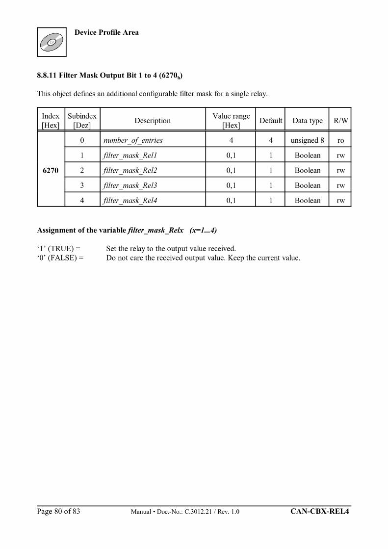
Device Profile Area
Manual • Doc.-No.: C.3012.21 / Rev. 1.0 CAN-CBX-REL4 Page 80 of 83
8.8.11 Filter Mask Output Bit 1 to 4 (6270h)
This object defines an additional configurable filter mask for a single relay.
Index[Hex]
Subindex[Dez] Description Value range
[Hex] Default Data type R/W
6270
0 number_of_entries 4 4 unsigned 8 ro
1 filter_mask_Rel1 0,1 1 Boolean rw
2 filter_mask_Rel2 0,1 1 Boolean rw
3 filter_mask_Rel3 0,1 1 Boolean rw
4 filter_mask_Rel4 0,1 1 Boolean rw
Assignment of the variable filter_mask_Relx (x=1...4)
‘1’ (TRUE) = Set the relay to the output value received.‘0’ (FALSE) = Do not care the received output value. Keep the current value.
Manufacturer Specific Profile Area
CAN-CBX-REL4 Manual • Doc.-No.: C.3012.21 / Rev. 1.0 Page 81 of 83
8.9 Manufacturer Specific Profile Area
Attention: The objects of the Manufacturer Specific Profile Area must not be changed by theuser!
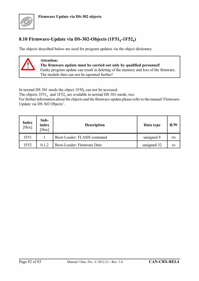
Firmware Update via DS-302 objects
Manual • Doc.-No.: C.3012.21 / Rev. 1.0 CAN-CBX-REL4 Page 82 of 83
8.10 Firmware-Update via DS-302-Objects (1F51h-1F52h)
The objects described below are used for program updates via the object dictionary.
Attention: The firmware update must be carried out only by qualified personnel! Faulty program update can result in deleting of the memory and loss of the firmware.The module then can not be operated further!
In normal DS 301 mode the object 1F50h can not be accessed.The objects 1F51h and 1F52h are available in normal DS 301-mode, too.For further information about the objects and the firmware-update please refer to the manual ‘Firmware-Update via DS 302 Objects’.
Index[Hex]
Sub-index[Hex]
Description Data type R/W
1F51 1 Boot-Loader: FLASH command unsigned 8 rw
1F52 0,1,2 Boot-Loader: Firmware Date unsigned 32 ro
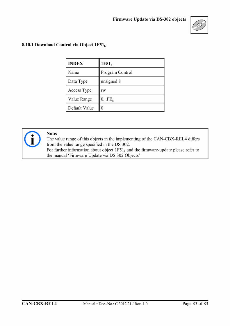
Firmware Update via DS-302 objects
CAN-CBX-REL4 Manual • Doc.-No.: C.3012.21 / Rev. 1.0 Page 83 of 83
i
8.10.1 Download Control via Object 1F51h
INDEX 1F51h
Name Program Control
Data Type unsigned 8
Access Type rw
Value Range 0...FEh
Default Value 0
Note:The value range of this objects in the implementing of the CAN-CBX-REL4 differsfrom the value range specified in the DS 302. For further information about object 1F51h and the firmware-update please refer tothe manual ‘Firmware Update via DS 302 Objects’