User's 3 Series Manual Coriolis Mass Flow and...
202
User's Manual IM 01R04B04-00E-E Rota Yokogawa GmbH & Co. KG Rheinstr. 8 D-79664 Wehr Germany IM 01R04B04-00E-E ©Copyright July 2003 (Rü) 7th edition, March 2009 (Rü) 3 Series Coriolis Mass Flow and Density Meter Integral Type RCCT3 Remote Type RCCF31 + RCCS3 Remote Type RCCR31 + RCCS3
-
Upload
duongkhuong -
Category
Documents
-
view
234 -
download
0
Transcript of User's 3 Series Manual Coriolis Mass Flow and...

User'sManual
IM 01R04B04-00E-E
Rota Yokogawa GmbH & Co. KGRheinstr. 8D-79664 WehrGermany
IM 01R04B04-00E-E©Copyright July 2003 (Rü)
7th edition, March 2009 (Rü)
3 SeriesCoriolis Mass Flow and Density MeterIntegral Type RCCT3Remote Type RCCF31 + RCCS3Remote Type RCCR31 + RCCS3

Blank Page
CONTENTS
i IM 01R04B04-00E-E 7th edition March 06, 2009 -00All Rights Reserved. Copyright © 2003, Rota Yokogawa
Contents
1. Introduction .........................................................................................1-1
1.1 Using the Coriolis Flowmeter Safely ............................................................1-2
1.2 Warranty ..........................................................................................................1-3
1.3 Instruction according EMC ............................................................................1-3
1.4 ATEX Documentation .....................................................................................1-4
1.5 Disposal, Cleaning and Return .....................................................................1-6
2. Transportation and Storage ...............................................................2-1
3. Product description ............................................................................3-1
3.1 The functional principle .................................................................................3-1
3.2 The Integral Type RCCT34 to 39/IR ..............................................................3-2
3.3 The Remote Field-Mount Converter RCCF31 ..............................................3-2
3.4 The Remote Rack-Mount Converter RCCR31 ..............................................3-3
3.5 The Remote Detector RCCS30 to 33 ............................................................3-4
3.6 The Remote Detector RCCS30 to 33 /Tx ......................................................3-4
3.7 The Remote Detector RCCS34 to 39/IR ........................................................3-5
3.8 The Remote Detector RCCS34 to 39/IR /Tx .................................................3-6
3.9 The Remote and Integral Type RCCx39/XR .................................................3-7
3.10 Measurement system and applications .....................................................3-8
3.11 Name Plates ..................................................................................................3-9
CONTENTS
iiIM 01R04B04-00E-E 7th edition March 06, 2009 -00 All Rights Reserved. Copyright © 2003, Rota Yokogawa
4. Installation ...........................................................................................4-1
4.1 General .......................................................................................................................................... 4-1
4.2 Mounting of detector RCCS30 to 33 option /PD ........................................... 4-1
4.3 Piping ...............................................................................................................4-2
4.4 Customer insulation .......................................................................................4-3
4.5 Mounting of converter RCCF31 to 2-inch pipe ............................................. 4-4
4.6 Mounting of converter RCCR31 in a subrack ............................................... 4-4
4.7 Alteration of display (RCCT3 / RCCF31) ......................................................4-5
4.8 Wiring ...............................................................................................................4-6
4.8.1 Assembling and connecting the Remote Cable RCCY03 ..................................4-6
4.8.2 Power supply wiring ........................................................................................... 4-8
4.8.3 Connecting to external instruments ................................................................ 4-10
4.8.4 Connecting HART- Communication ................................................................ 4-14
4.8.5 Flowmeters with intrinsic safe outputs........................................................... 4-14
5. Basic operating procedures ..............................................................5-1
5.1 Liquid crystal display .....................................................................................5-1
5.2 Display modes ................................................................................................5-3
5.3 Setting via keys ..............................................................................................5-4
5.4 Examples of parameter settings via keys ....................................................5-5
5.4.1 Display configuration, set volume flow to line 1 ............................................. 5-5
5.4.2 Setting Temperature 20-120°C to Analog Output 2 ........................................ 5-6
5.5 Setting parameters in converter with option /NC .......................................5-8
5.6 Zero adjustment (Autozero) ...........................................................................5-9
6. Operation via HART ............................................................................6-1
6.1 Conditions of Communication Line ..............................................................6-1
6.2 Communication via FieldMate .......................................................................6-2
6.3 Communication via HART Communicator ...................................................6-3
6.4 Unique functions of HART Communicator ..................................................6-4
6.5 Transmitting device variables via HART ......................................................6-5
6.6 Hardware Write Protect ..................................................................................6-6

CONTENTS
iii IM 01R04B04-00E-E 7th edition March 06, 2009 -00All Rights Reserved. Copyright © 2003, Rota Yokogawa
7. Parameter description ........................................................................7-1
7.1 Overview ..........................................................................................................7-1
7.2 Parameter list ..................................................................................................7-2
7.3 Parameter tree, Display menu .....................................................................7-16
7.4 Parameter tree, HART menu ........................................................................7-33
7.5 Mass flow functions (Basic or Detailed Setup) .........................................7-50
7.6 Volume flow functions (Basic or Detailed Setup) .....................................7-51
7.7 Density functions (Basic or Detailed Setup) .............................................7-52
7.8 Temperature functions (Basic or Detailed Setup) ....................................7-54
7.9 Velocity functions (Detailed Setup) ............................................................7-55
7.10 Analog 1 functions (Basic or Detailed Setup) .........................................7-55
7.11 Analog 2 functions (Basic or Detailed Setup) .........................................7-56
7.14 Status input functions (Basic or Detailed Setup) ...................................7-64
7.15 Totalizer functions (Basic or Detailed Setup) .........................................7-65
7.16 Flow direction function (Detailed Setup) .................................................7-66
7.17 Concentration measurement (Detailed Setup) ........................................7-66
7.18 Net flow (Detailed Setup) ...........................................................................7-68
7.19 Slug detection (Detailed Setup) ................................................................7-69
7.20 Empty pipe detection (Detailed Setup) ....................................................7-71
7.21 Corrosion detection (Detailed Setup) .......................................................7-72
7.22 Detector data (Detailed Setup) ..................................................................7-72
7.23 Autozero (Diag/Service) .............................................................................7-73
7.24 Reading maximum fluid temperature (Detailed Setup) ..........................7-74
7.25 Option /GA for Gas Measurement ............................................................7-74

CONTENTS
ivIM 01R04B04-00E-E 7th edition March 06, 2009 -00 All Rights Reserved. Copyright © 2003, Rota Yokogawa
8. Self-diagnostic and Troubleshooting ...............................................8-1
8.1 Error descriptions and countermeasure .......................................................8-1
8.2 Reading Event + Error History (Diag/Service, Self test/Status) ................8-4
8.3 Self test (Diag/Service) ...................................................................................8-5
8.4 Signal- and I/O-Test (Diag/Service) ...............................................................8-5
8.5 Output trim ......................................................................................................8-5
8.6 Detector cleaning ............................................................................................8-6
8.7 Troubleshooting ..............................................................................................8-6
8.7.1 No indication ........................................................................................................ 8-6
8.7.2 No Key-setting possible ..................................................................................... 8-7
8.7.3 No HART communication ................................................................................... 8-7
8.7.4 Unstable zero ....................................................................................................... 8-8
8.7.5 Disagreement of indication with actual flow rate ............................................ 8-9
8.7.6 Disagreement of indication with actual density............................................. 8-10
8.7.7 Disagreement of indication with actual temperature .................................... 8-11
8.7.8 Discrepancy of output signals to the assigned measurand......................... 8-12
8.7.9 Setting "Burn-out" mode .................................................................................. 8-13
8.8 Detection of metering tube failure ..............................................................8-14

CONTENTS
v IM 01R04B04-00E-E 7th edition March 06, 2009 -00All Rights Reserved. Copyright © 2003, Rota Yokogawa
9. Explosion protected type instruments ................................................ 9-1
9.1 ATEX ................................................................................................................9-1
9.1.1 Technical Data ..................................................................................................... 9-1
9.1.2 Installation ............................................................................................................ 9-4
9.1.3 Operation .............................................................................................................. 9-7
9.1.4 Maintenance and repair ...................................................................................... 9-7
9.1.5 Ex-relevant marking on name plates (refer to chapter 3.11) .......................... 9-7
9.2 FM (USA + Canada) .......................................................................................9-9
9.2.1 Technical Data ..................................................................................................... 9-9
9.2.2 Installation .......................................................................................................... 9-10
9.2.3 General warnings .............................................................................................. 9-12
9.2.4 Ex-relevant marking on name plates (refer to chapter 3.11) ........................ 9-13
9.2.5 Control drawings ............................................................................................... 9-14
9.3 IECEx ..............................................................................................................9-19
9.3.1 Technical Data ................................................................................................... 9-19
9.3.2 Installation .......................................................................................................... 9-21
9.3.3 Operation ............................................................................................................ 9-24
9.3.4 Maintenance and repair .................................................................................... 9-24
9.3.5 Ex-relevant marking on name plates (refer to chapter 3.11) ........................ 9-25
9.4 INMETRO (Brazil) ..........................................................................................9-26
10. PED (Pressure Equipment Directive) .............................................10-1
11. Technical Data .................................................................................11-1
11.1 Specifications ..............................................................................................11-1
11.2 Dimensions ..................................................................................................11-7
11.3 Model-, Suffix- and Option-codes ...........................................................11-13

CONTENTS
viIM 01R04B04-00E-E 7th edition March 06, 2009 -00 All Rights Reserved. Copyright © 2003, Rota Yokogawa
Blank Page

1. INTRODUCTION
1-1 IM 01R04B04-00E-E 7th edition March 06, 2009 -00All Rights Reserved. Copyright © 2003, Rota Yokogawa
1. Introduction
This instrument has been adjusted at the factory before shipment.
To ensure correct use of the instrument, please read this manual thoroughly and fully understand how to operate the instrument before operating it.
NOTE
This manual describes the hardware and soft-ware configurations of the ROTAMASS Coriolis Massflowmeter.
Regarding This User's Manual
• This manual should be provided to the end user.• Before use, read this manual thoroughly to com-
prehend its contents.• The contents of this manual may be changed
without prior notice.• All rights are reserved. No part of this manual
may be reproduced in any form without Yokoga-wa's written permission.
• Yokogawa makes no warranty of any kind with regard to this material, including, but not limited to, implied warranties of merchantability and suitability for a particular purpose.
• All reasonable effort has been made to ensure the accuracy of the contents of this manual. However, if any errors or omissions are found, please inform Yokogawa.
• Yokogawa assumes no responsibilities for this product except as stated in the warranty.
• Please note that this user's manual may not be revised for any specification changes, construction changes or operating part changes that are not considered to affect function or performance.
• If the customer or any third party is harmed by the use of this product, Yokogawa assumes no responsibility for any such harm owing to any defects in the product which were not predict-able, or for any indirect damages.
Safety and Modification Precautions
• The following general safety precautions must be observed during all phases of operation, service, and repair of this instrument. Failure to comply with these precautions or with specific WARNINGS given elsewhere in this manual violates safety standards of design,manufacture, and intended use of the instrument. Yokogawa assumes no liability for the customer's failure to comply with these requirements. If this instrument is used in a manner not specified in this manual, the protection provided by this instrument may be impaired.
• The following safety symbol marks are used in this user's manual and instrument.
WARNING
A WARNING sign denotes a hazard. It calls attention to procedure, practice, condition or the like, which, if not correctly performed or adhered to, could result in injury or death of personnel.
CAUTION
A CAUTION sign denotes a hazard. It calls attention to procedure, practice, condition or the like, which, if not correctly performed or adhered to, could result in damage to or destruction of part or all of the product.
IMPORTANT
An IMPORTANT sign denotes that attention is required to avoid damage to the instrument or system failure.
NOTE
A NOTE sign denotes information necessary for essential understanding of operation and features.

1. INTRODUCTION
1-2IM 01R04B04-00E-E 7th edition March 06, 2009 -00 All Rights Reserved. Copyright © 2003, Rota Yokogawa
Protective grounding terminal
Functional grounding terminal (This terminal should not be used as a pro-tective grounding terminal.)
Alternating current
Direct current
1.1 Using the Coriolis Flowmeter Safely
WARNING
(1) Installation• Installation of the Coriolis flowmeter must be
performed by expert engineer or skilled personnel. No operator shall be permitted to perform procedures relating to installation.
• The Coriolis flowmeter is a heavy instrument. Be careful that no damage is caused to personnel through accidentally dropping it, or by exerting
excessive force on the Coriolis flowmeter. When moving the Coriolis flowmeter, always use a trolley and have at least two people carry it.
• When the Coriolis flowmeter is processing hot fluids, the instrument itself may become extremely hot. Take sufficient care not to get burnt.
• Where the fluid being processed is a toxic sub-stance, avoid contact with the fluid and avoid inhaling any residual gas, even after the instru-ment has been taken off the line for
maintenance and so forth.• All procedures relating to installation must comply
with the electrical code of the country where it is used.
(2) Wiring• The wiring of the Coriolis flowmeter must be
performed by expert engineer or skilled personnel. No operator shall be permitted to perform
procedures relating to wiring.• When connecting the wiring, check that the
supply voltage is within the range of the voltage specified for this instrument before connecting the power cable. In addition, check that no voltage is applied to the power cable before connecting the wiring.
• The protective grounding must be connected securely at the terminal with the mark to avoid danger to personnel.
(3) Operation• Do not open the cover until the power has been
off for at least 10 minutes. Only expert engineer or skilled personnel are permitted to open the cover.
(4) Maintenance• Maintenance on the Coriolis flowmeter should
be performed by expert engineer or skilled personnel. No operator shall be permitted to perform any operations relating to maintenance.
• Always conform to maintenance procedures outlined in this manual. If necessary, contact Yokogawa.
• Care should be taken to prevent the build up of dirt, dust or other substances on the display panel glass or data plate. If these surfaces do get dirty, wipe them clean with a soft dry cloth.
(5) European Pressure Equipment Directive (PED)
• When using the instrument as a PED-compliant product, be sure to read Chapter 10 before
use.(6) Hazardous Duty Type Instruments
• For explosion proof type instruments the
description in chapter 9 "EXPLOSION PRO-
TECTED TYPE INSTRUMENT" has priority to the other descriptions in this instruction manual. • All instruction manuals for ATEX Ex related products are available in English, German and French. Should you require Ex related instruc-tions in your local language, you should contact your nearest Yokogawa office or representative. • Only trained personal should install and maintain instruments in hazardous areas. • The protective grounding terminal must be connected to a suitable IS grounding system. • Avoid mechanical generated sparks while working on the equipment and peripherial devices in hazardous areas.

1. INTRODUCTION
1-3 IM 01R04B04-00E-E 7th edition March 06, 2009 -00All Rights Reserved. Copyright © 2003, Rota Yokogawa
1.2 Warranty• The warranty terms of this instrument that are
guaranteed are described in the quotation. We will make any repairs that may become neces-sary during the guaranteed term free of charge.
• Please contact our sales office if this instrument requires repair.
• If the instrument is faulty, contact us with com-plete details about the problem and the length of time it has been faulty, and state the model and serial number. We would appreciate the inclu-sion of drawings or additional information.
• The results of our examination will determine whether the meter will be repaired free of charge or on an at-cost basis.
The guarantee will not apply in the following cases:
• Damage due to negligence or insufficient main-tenance on the part of the customer.
• Problems or damage resulting from handling, operation or storage that violates the intended use and specifications.
• Problems that result from using or performing maintenance on the instrument in a location that does not comply with the installation location specified by Yokogawa.
• Problems or damage resulting from repairs or modifications not performed by Yokogawa or someone authorized by Yokogawa.
• Problems or damage resulting from inappropri-ate installation after delivery.
• Problems or damage resulting from disasters such as fires, earthquakes, storms, floods, or lightning strikes and external causes.
1.3 Instruction according EMC
The ROTAMASS Coriolis flowmeter is conform to the European EMC Guideline and fulfills the following standards:
EN 61326-1: 2006;
EN 61326-2-3: 2006;
EN 61000-3-2: 2006;
EN 61000-3-3: 1995+A1+A2
ROTAMASS is a class A product and should be used and installed properly according to the EMC Class A requirements
Installation
The function ground terminal or the PE- terminal have to be connected to protective ground to ensure electro-magnetic interference protection.
To ensure the EMC specifications the following
measures must be carried out :
1. Put the power cables through the ferrite core
clamp before connecting to the terminals as shown
in chapter ´ Installation ´ (Power supply wiring).
2. Put the I/O- cables through the ferrite core
clamp before connecting to the terminals as shown
in chapter ´ Installation ´ (Power supply wiring).
3. Connect protective ground conductor of power
supply to PE- terminal in the terminal box (see
chapter ´ Installation ´ (Power supply wiring).
4. In case of Explosion proof type instrument, fur-
ther requirements are described in chapter 9
“EXPLOSION PROTECTED TYPE INSTRUMENTS”.
The description in this chapter is prior to other de-
scriptions in this instruction manual.
Restriction on Use of Radio Transceiver :
IMPORTANT
Although the products has been designed to resist high frequency electrical noise, if a radio transceiver is used near the flowmeter or its external wiring, the transmitter may be affected by high frequency noise pickup. To test for such effects, bring the transceiver in use slowly from a distance of several meters from the flowmeter, and observe the measurement loop for noise effects. Thereafter, always use the transceiver outside the area affected by noise.
CAUTION

1. INTRODUCTION
1-4IM 01R04B04-00E-E 7th edition March 06, 2009 -00 All Rights Reserved. Copyright © 2003, Rota Yokogawa
1.4 ATEX DocumentationThis procedure is only applicable to the countries in European Union.
GB
All instruction manuals for ATEX Ex related prod-ucts are available in English, German and French. Should you require Ex related instructions in your local language, you are to contact your nearest Yokogawa office or representative.
DK
Alle brugervejledninger for produkter relateret til ATEX Ex er tilgængelige på engelsk, tysk og fransk. Skulle De ønske yderligere oplysninger om håndtering af Ex produkter på eget sprog, kan De rette henvendelse herom til den nærmeste Yokogawa afdeling eller forhandler.
I
Tutti i manuali operativi di prodotti ATEX contras-segnati con Ex sono disponibili in inglese, tede-sco e francese. Se si desidera ricevere i manuali operativi di prodotti Ex in lingua locale, mettersi in contatto con l’ufficio Yokogawa più vicino o con un rappresentante.
E
Todos los manuales de instrucciones para los productos antiexplosivos de ATEX están dis-ponibles en inglés, alemán y francés. Si desea solicitar las instrucciones de estos artículos antiexplosivos en su idioma local, deberá ponerse en contacto con la oficina o el representante de Yokogawa más cercano.
NL
Alle handleidingen voor producten die te maken hebben met ATEX explosiebeveiliging (Ex) zijn verkrijgbaar in het Engels, Duits en Frans. Neem, indien u aanwijzingen op het gebied van explosie-beveiliging nodig hebt in uw eigen taal, contact op met de dichtstbijzijnde vestiging van Yokogawa of met een vertegenwoordiger.
SF
Kaikkien ATEX Ex -tyyppisten tuotteiden käyt-töhjeet ovat saatavilla englannin-, saksan- ja ranskankielisinä. Mikäli tarvitset te Ex -tyyppisten tuotteiden ohjeita omalla paikallisella kielellännne, ottakaa yhteyttä lähimpään Yokogawa- toimistoon tai -edustajaan.
P
Todos os manuais de instruções referentes aos produtos Ex da ATEX estão disponíveis em In-glês, Alemão e Francês. Se necessitar de instru-ções na sua língua relacionadas com produtos Ex, deverá entrar em contacto com a delegação mais próxima ou com um representante da Yoko-gawa.
F
Tous les manuels d’instruction des produits ATEX Ex sont disponibles en langue anglaise, allemande et française. Si vous nécessitez des instructions relatives aux produits Ex dans votre langue, veuillez bien contacter votre représentant Yokogawa le plus proche.
D
Alle Betriebsanleitungen für ATEX Ex bezoge-ne Produkte stehen in den Sprachen Englisch, Deutsch und Französisch zur Verfügung. Sollten Sie die Betriebsanleitungen für Ex-Produkte in Ihrer Landessprache benötigen, setzen Sie sich bitte mit Ihrem örtlichen Yokogawa-Vertreter in Verbindung.
S
Alla instruktionsböcker för ATEX Ex (explosions-säkra) produkter är tillgängliga på engelska, tyska och franska. Om Ni behöver instruktioner för dessa explosionssäkra produkter på annat språk, skall Ni kontakta närmaste Yokogawa kontor eller representant.

1. INTRODUCTION
1-5 IM 01R04B04-00E-E 7th edition March 06, 2009 -00All Rights Reserved. Copyright © 2003, Rota Yokogawa
GR
Ολα τα εγχειριδια λειτουργιαζ τωυ προιουτϖυ µε ΑΤΕX Εx διατιΘευται στα Αγγλικα, Γερµαυικα και Γαλλικα. Σε περιπτωση που χρειαζεοτε οδηγιεζ σχετικα µε Ex στηυ τοπικη γλωσσα παρακαλουµε επικοιυωυηστε µε το πλησιεστερο γραϕειο τηζ Yokogawa η αντιπροσωπο τηζ.
SK
Všetky návody na obsluhu pre prístroje s ATEX Ex sú k dispozícii v jazyku anglickom, nemeckom a francúzskom. V prípade potreby návodu pre Ex-prístroje vo Vašom národnom jazyku, skontaktujte prosím miestnu kanceláriu firmy Yokogawa.
CZ
Všechny uživatelské příručky pro výrobky, na něž se vztahuje nevýbušné schválení ATEX Ex, jsou dostupné v angličtině , němčině a francouzštině . Požadujete-li pokyny týkající se výrobků s nevýbušným schválením ve vašem lokálním jazyku, kontaktujte prosím vaši nejbližší reprezentační kancelář Yokogawa.
Visos gaminiø ATEX Ex kategorijos Eksploatavimo instrukcijos teikiami anglø, vokieèiø ir prancûzø kalbomis. Norëdami gauti prietaisø Ex dokumen-tacijà kitomis kalbomis susisiekite su artimiausiu bendrovës “Yokogawa” biuru arba atstovu.
LVVisas ATEX Ex kategorijas izstrâdâjumu Lietoða-nas instrukcijas tiek piegâdâtas angïu, vâcu un franèu valodâs. Ja vçlaties saòemt Ex ierîèu doku-mentâciju citâ valodâ, Jums ir jâsazinâs ar firmas Jokogava (Yokogawa) tuvâko ofisu vai pârstâvi..
ESTKõik ATEX Ex toodete kasutamisjuhendid on esi-tatud inglise, saksa ja prantsuse keeles. Ex sead-mete muukeelse dokumentatsiooni saamiseks pöörduge lähima Iokagava (Yokogawa) kontori või esindaja poole.
LT
PL
Wszystkie instrukcje obsługi dla urządzeń w wykonaniu przeciwwybuchowym Ex, zgodnych z wymaganiami ATEX, dostępne są w języku angielskim, niemieckim i francuskim. Jeżeli wymagana jest instrukcja obsługi w Państwa lokalnym ję zyku, prosimy o kontakt z najbliższym biurem Yokogawy.
SLO
Vsi predpisi in navodila za ATEX Ex soro-dni pridelki so pri roki v anglišèini, nemšèini ter francošèini. Èe so Ex sorodna navodila potrebna v vašem tukejnjem jeziku, kontaktirajte vaš najbliši Yokogawa office ili predstaunika.
H
Az ATEX Ex mûszerek gépkönyveit angol, német és francia nyelven adjuk ki. Amennyiben helyi nyelven kérik az Ex eszközök leírásait, kérjük ke-ressék fel a legközelebbi Yokogawa irodát, vagy képviseletet.
BG
Всички упътвания за продукти от серията АТЕХЕх се предлагат на английски, немски ифренски език. Ако се нуждаете от упътванияза продукти от серията Ех на родния ви език,се свържете с най-близкия офис илипредставителство на фирма Yokogawa.
RO
Toate manualele de instructiuni pentru produsele ATEX Ex sunt in limba engleza, germana si franceza. In cazul in care doriti instructiunile in limba locala, trebuie sa contactati cel mai apropiat birou sau reprezentant Yokogawa.
MIl-manwali kollha ta’ l-istruzzjonijiet għal prodotti marbuta ma’ ATEX Ex huma disponibbli bl-Ingliż, bil-Ġermaniż u bil-Franċiż. Jekk tkun teħtieġ struzzjonijiet marbuta ma’ Ex fil-lingwa lokali tiegħek, għandek tikkuntattja lill-eqreb rappreżentan jew uffiċċju ta’ Yokogawa.

1. INTRODUCTION
1-6IM 01R04B04-00E-E 7th edition March 06, 2009 -00 All Rights Reserved. Copyright © 2003, Rota Yokogawa
1.5 Disposal, Cleaning and Return
For safe use
WARNING
If the process fluid is harmful to personnel, handle
the instrument carefully even after it has been
removed from the process line for maintenance or
other purposes. Exercise extreme care to prevent
the fluid from coming into contact with human skin
and to avoid inhaling any residual gas. Before
sending it to the Seller for examination and/or
repair please clean the instrument thoroughly and
make sure, that no harmful chemicals are in or
at the meter. If the instrument contains unknown
fluids the Seller will send it back to the Purchaser
for cleaning on their cost.
WARNING
ROTAMASS might be heavy instruments. Please
give attention to prevent that persons are not
injured by carrying or installing. It is preferable
when carrying the instrument to use a cart and
be done by two or more persons. When removing
the instrument from hazardous processes, avoid
contact with the fluid and the interior of the meter.
the failure occurred. It will be helpful if schematic
diagrams and/or records of data are attached to
the failed instrument. Whether or not the failed
instrument should be repaired free of charge shall
be left solely to the discretion of the Seller as a
result of an inspection by the Seller.
The Purchaser shall not be entitled to receive re-
pair services from the Seller free of charge, even
during the warranty period, if the malfunction or
damage is due to improper and/or inadequate
maintenance of the instrument in question by the
Purchaser handling, use or storage of the instru-
ment in question beyond the design and/or speci-
fications requirements, use of the instrument in
question in a location no conforming to the condi-
tions specified in the Seller’s General Specification
or Instruction Manual retrofitting and/or repair by
an other party than the Seller or a party to whom
the Seller has entrusted repair services. improper
relocation of the instrument in question after
delivery reason of force measure such as fires,
earthquakes, storms/ floods, thunder/lightning, or
other reasons not attributable to the instrument in
question.
For disposal and recycling please refer to your na-
tional regulations.
Please find following help. After remove of all
products rests the instruments can be disassem-
bled and the parts treated different.
Naming: R = recycling, D = disposal, Sd = special
disposal, Na = not applicable Name
of product
Body Converter housing
Cover with window
Elec-tron-ics
Rota-mass
SS R Al R Al + Glass
D Sd
In case of return of flow meters to Yokogawa for
testing or repair purposes please fill out one of the
following forms and send it with the equipment to
YOKOGAWA.
Warranty
The warranty of the instruments shall cover the
period noted on the quotation presented to the
purchaser at the time of purchase. The Seller shall
repair the instrument free of charge when the fail-
ure occurred during the warranty period.
All inquiries on instrument failure should be direct-
ed to the Seller’s sales representative from whom
you purchased the instrument or your nearest
sales office of the Seller.
Should the instrument fail, contact the Seller,
specifying the model and instrument number of the
product in question. Be specific in describing
details on the failure and the process in which

1. INTRODUCTION
1-7 IM 01R04B04-00E-E 7th edition March 06, 2009 -00All Rights Reserved. Copyright © 2003, Rota Yokogawa
Receiver : Sender :
Delivery Note (for EU-Countries) Date :
Ref. REPAIR for serial no. __________________________
We are sending following type of articlevia forwarding agent : Yusen Air ; Raunheim/Frankfurt
Item Article Unit Price Total Price
Type (MS-Code)________________________________ € __________ €__________
Charges for airworthy packingand delivery FOB €___________
Total value € ___________
Value for customs purpose only € _________
(nominal value)
(current value)
Gross weight . _____________________kgNet weight : _____________________kgCustoms Tariff No. : _____________________Country og origin : Federal Republic of Germany
Delivery note 2-fold accompanis the goods
SPECIMEN Certificate
Company : ________________________ Address : ______________________Department : ________________________ Name : ______________________Telephone : ________________________ Fax : ______________________ The attached flowmeter :
Type : ______________________________ Order- or Serial No. ___________
has been operated with following liquids: ___________________________________________
Because the liquid is water-endangering toxic caustic flammablewe have
checked, that all cavities in the flowmeter are free from such substances flushed out and neutralised all cavities in the flowmeter
Please check applicable descriptionWe confirm that there is no risk to man or enviroment through any residual liquid containes in this flowmeter.
Date : _____________________ Signature : _______________________
Company stamp:

1. INTRODUCTION
1-8IM 01R04B04-00E-E 7th edition March 06, 2009 -00 All Rights Reserved. Copyright © 2003, Rota Yokogawa
Receiver : Sender :
PROFORMA INVOICE (for Third-party-Countries) Date :
Ref. REPAIR for serial no. __________________________
We are sending following type of articlevia forwarding agent : Yusen Air ; Raunheim/Frankfurt
Item Article Unit Price Total Price
Type (MS-Code)________________________________ € __________ €__________
Charges for airworthy packingand delivery FOB €___________
Total value € ___________
Value for customs purpose only € _________
(nominal value)
(current value)
Gross weight . _____________________kgNet weight : _____________________kgCustoms Tariff No. : _____________________Country og origin : Federal Republic of Germany
Delivery note 2-fold accompanis the goods
SPECIMEN Certificate
Company : ________________________ Address : ______________________Department : ________________________ Name : ______________________Telephone : ________________________ Fax : ______________________ The attached flowmeter :
Type : ______________________________ Order- or Serial No. ___________
has been operated with following liquids: ___________________________________________
Because the liquid is water-endangering toxic caustic flammablewe have
checked, that all cavities in the flowmeter are free from such substances flushed out and neutralised all cavities in the flowmeter
Please check applicable descriptionWe confirm that there is no risk to man or enviroment through any residual liquid containes in this flowmeter.
Date : _____________________ Signature : _______________________
Company stamp:

2. TRANSPORTATION AND STORAGE
2-1 IM 01R04B04-00E-E 7th edition March 06, 2009 -00All Rights Reserved. Copyright © 2003, Rota Yokogawa
2. Transportation and Storage
Transport instructions
When transporting the instrument, you must observe the following safety instructions in order to avoid lethal
injury, damage to the instrument and other material damage.
The steps involved in transport may only be carried out by qualified persons taking into
account the safety instructions.
• Observe the transport instructions on the packaging.
• Observe the below mentioned storage conditions.
• Use only the original packaging.
• The packaging material must be disposed of in accordance with the regulations.
• The transport braces must not be removed until installation.
• Read the chapter “Safety instructions”.
• To avoid any damages, unpack the flowmeter only at the installation site.
• Mechanical shocks are to be avoided.
ROTAMASS is a heavy instrument. Please be careful to prevent persons from injuring when it is handled.
Storage conditions
Please note the following for storage purposes :
The detector and converter should be stored in its transport packaging.
Choose a storage place that meets the following requirements:
• Protection from rain and humidity• Free of mechanical vibration and shocks• Ambient Temperature between -40°C to 55°C (RCCT3 / RCCF31 / RCCR31) -50°C to 80°C (RCCS3)
• Atmospheric humidity ranging from 0 to 100%.
Before storing a used flowmeter remove any fluid from the flowmeter line completely.
Properties of the instrument can change when stored outdoors.
WARNING

2. TRANSPORTATION AND STORAGE
2-2IM 01R04B04-00E-E 7th edition March 06, 2009 -00 All Rights Reserved. Copyright © 2003, Rota Yokogawa
Blank Page

3. Product description
3-1 IM 01R04B04-00E-E 7th edition March 06, 2009 -00All Rights Reserved. Copyright © 2003, Rota Yokogawa
3. Product description
3.1 The functional principleThe ROTAMASS instrument measures the mass flow with the help of the so-called Coriolis force. This force
occurs, when the medium being measured is flowing at velocity ν through a tube that is rotating around an
axis perpendicular to the direction of flow at
angular velocity ϖ.
When the medium moves away from the axis of rotation it must be accelerated to an
increasingly high peripheral velocity. The force required for this is called Coriolis force, after its discoverer.
The Coriolis force reduces the rotation. The opposite effect occurs, when the medium flows towards the axis
of rotation. Then the Coriolis force amplifies the rotation.
The formula for the Coriolis force is as follows:
Fc = - 2 m (ϖ x ν )
The entire measurement tube is deformed slightly by the Coriolis forces, in the way shown. This deformation
is registered by movement sensors at points S1 and S2 .
For practical exploitation of this physical principle, it is sufficient for the tube to perform sympathetic
oscillations on a small section of a circular path. This is achieved by exciting the measurement tube at point
E by means of an electromagnetic exciter.
The general construction of a Coriolis mass flowmeter looks as followed:
Driver coil
Sensor coils
Temperature sensor

3. Product description
3-2IM 01R04B04-00E-E 7th edition March 06, 2009 -00 All Rights Reserved. Copyright © 2003, Rota Yokogawa
3.3 The Remote Field-Mount Converter RCCF31
The following drawing shows the general construction of the remote field-mount converter.
F32.EPS
Display
Terminal Box Power and I/O
Terminal Box Detector Connection
Power supply inlet
I/O inlet
3.2 The Integral Type RCCT34 to 39/IR
The following drawing shows the general construction of the integral type ROTAMASS
F31.EPS
Terminal Box Power and I/ODisplay
Name Plate
Detector Assembly
Flow direction arrow
Power supply conduit
I/O - line conduit

3. Product description
3-3 IM 01R04B04-00E-E 7th edition March 06, 2009 -00All Rights Reserved. Copyright © 2003, Rota Yokogawa
3.4 The Remote Rack-Mount Converter RCCR31
The following drawing shows the general construction of the remote rack-mount converter.
Terminal Board
F35.EPS
19-inch Cassette
Display and infrared switches
PE
PE
D+D-S1+S1-S2+S2-TP1TP2TP3COM
Iout1+Iout1-Iout2+Iout2-Pout+Pout-Sin+Sin-Sout+Sout-
L/+
N/-
G
Detector connection terminals
Input /Output terminals
Powerterminals
Groundterminals

3. Product description
3-4IM 01R04B04-00E-E 7th edition March 06, 2009 -00 All Rights Reserved. Copyright © 2003, Rota Yokogawa
3.5 The Remote Detector RCCS30 to 33The following drawing shows the general construction of the remote detector RCCS30 to 33.
Terminal BoxName plate
3.6 The Remote Detector RCCS30 to 33 /TxThe following drawing shows the general construction of the remote detector RCCS30 to 33 /Tx.
Dimensions in mmWeight (without process flanges): 12kg
F37.EPS
see table 8
Terminal Box
Process connection
Heating connection
Ventilation optional /T3
Factory insulation
Name plate
3. Product description
3-5 IM 01R04B04-00E-E 7th edition March 06, 2009 -00All Rights Reserved. Copyright © 2003, Rota Yokogawa
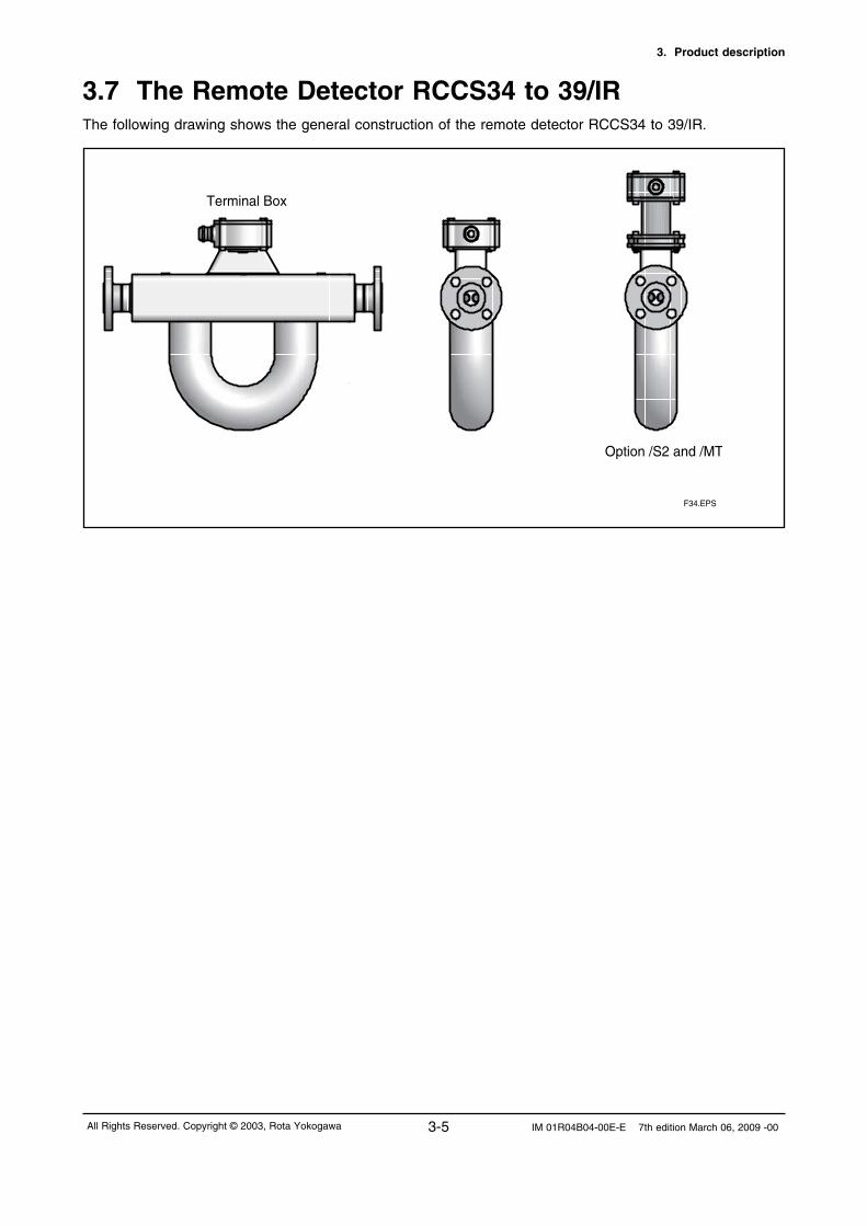
3.7 The Remote Detector RCCS34 to 39/IRThe following drawing shows the general construction of the remote detector RCCS34 to 39/IR.
F34.EPS
Terminal Box
Option /S2 and /MT
3. Product description
3-6IM 01R04B04-00E-E 7th edition March 06, 2009 -00 All Rights Reserved. Copyright © 2003, Rota Yokogawa
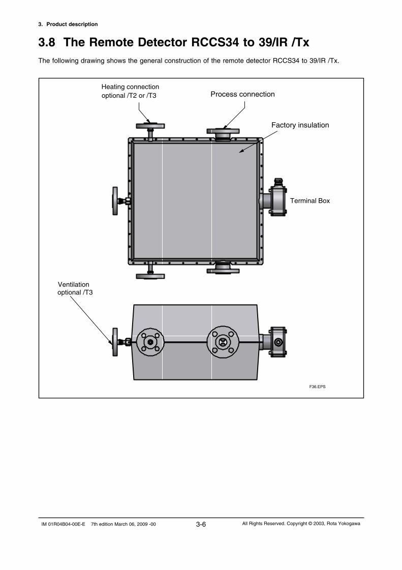
3.8 The Remote Detector RCCS34 to 39/IR /TxThe following drawing shows the general construction of the remote detector RCCS34 to 39/IR /Tx.
Process connectionoptional /T2 or /T3Heating connection
Terminal Box
Factory insulation
Ventilationoptional /T3
F36.EPS

3. Product description
3-7 IM 01R04B04-00E-E 7th edition March 06, 2009 -00All Rights Reserved. Copyright © 2003, Rota Yokogawa
3.9 The Remote and Integral Type RCCx39/XRThe following drawing shows the general construction of the RCCx39/XR.
Option /S2 and /MT
F38.EPS
Terminal Box
Integral Type RCCT39/XR
Remote Type RCCS39/XR

3. Product description
3-8IM 01R04B04-00E-E 7th edition March 06, 2009 -00 All Rights Reserved. Copyright © 2003, Rota Yokogawa
3.10 Measurement system and applicationsROTAMASS measures the mass flow of fluids directly.The measurement system uses the Coriolis principle and is suitable for a wide range of continuous flow measurement applications in all branches of process technology.ROTAMASS has two components: the detector and the converter.The detector measures the mass flow directly and converts it into electrical signals.The converter evaluates the electrical signals and outputs the following values:
- mass flow, independent of media properties, such as density, temperature, viscosity- fluid density- fluid temperature
The values are displayed or output as electrical values for use by other systems.The converter is operated with the help of three infra-red keys and a 4-line display and is standard equipped with HART-communication protocol.
ROTAMASS is suitable for- measuring liquids, liquids with solid content, multi-phase mixtures;- measuring gases (restricted by density and pressure loss)- measuring the substance concentrations in mixtures of substances;- simultaneous measurement of mass flow, density, temperature, volume flow and cumulated mass and volume;- connection to controllers and process control systems
ROTAMASS provides the following I/O-connections and can be configured for a wide variety of different measurement applications (controlling, checking, monitoring, metering, mixing, filling).
- 2 analog outputs
- 2 passive pulse outputs / status outputs
- 1 status input
optional (/AP) :- 1 active pulse output / status output, (Pout)
optional (/NM) :- 1 pulse output / status output according EN50227 (NAMUR), (Pout) optional (/KF2) : - 1 analog output (Ex ia) - 1 passive pulse output / status output (Ex ia) These capabilities make ROTAMASS ideal for the increasing demand of requirements for automation and the growing trend towards batch processes.
optional (/FB) see IM 01R04B05-00E-E : - 1 Foundation Fieldbus communication line
optional (/FB and /KF4) see IM 01R04B05-00E-E : - 1 intrinsic safe (Ex ia) Foundation Fieldbus communication line

3. Product description
3-9 IM 01R04B04-00E-E 7th edition March 06, 2009 -00All Rights Reserved. Copyright © 2003, Rota Yokogawa
3.11 Name PlatesName plate of Integral type RCCT3:
1 Model code 2 Serial number same as order number 3 Ambient temperature range 4 Current output range and load resistance range 5 Power supply range 6 Maximum supply voltage and maximum current for passive pulse- and status- output 7 Calibration constants of detector (see also on calibration certificate) 8 Number of notified body according ATEX (only for ATEX certified flowmeters) 9 Number of notified body according PED (only for units with process connections greater than DN25) 10 Area for Ex- relevant marking (see chapter 9). The CE-mark is not present for FM-approved units. 11 PS = maximum permissible pressure 12 TS = maximum permissible process temperature 13 Material of metering tubes 14 Year of manufacturing 15 Customer specified tag number if option /BG was ordered
Name plate of Remote Converter RCCF31 / RCCR31:
1 Model code 2 Serial number same as order number 3 Year of manufacturing 4 Ambient temperature range 5 Power supply range 6 Current output range and load resistance range 7 Maximum supply voltage and maximum current for passive pulse output 8 Maximum supply voltage and maximum current for passive status output 9 Number of notified body according ATEX (only for ATEX certified flowmeters) 10 Area for Ex- relevant marking (see chapter 9). The CE-mark is not present for FM-approved units. 11 Customer specified tag number if option /BG was ordered
0344
0038
1 2 3 4 5 6 7
8 9 10 11 12 13 14 15
1 2 3 4 5 6
0344
7 8
9 10 11

3. Product description
3-10IM 01R04B04-00E-E 7th edition March 06, 2009 -00 All Rights Reserved. Copyright © 2003, Rota Yokogawa
Name plate of Remote Detector RCCS3:
1 Model code 2 Serial number same as order number 3 Calibration constants of detector (see also on calibration certificate) 4 Number of notified body according ATEX (only for ATEX certified flowmeters) 5 Number of notified body according PED (only for units with process connections greater than DN25) 6 Area for Ex- relevant marking (see chapter 9). The CE-mark is not present for FM-approved units. 7 PS = maximum permissible pressure 8 TS = maximum permissible process temperature 9 Material of metering tubes 10 Year of manufacturing 11 Customer specified tag number if option /BG was ordered
Name plate of RCCT3 and RCCS3 with option /DS (Dual Seal approval):In general the name plates of these units are the same as shown above.The difference is as followed: PS is named as "Working pressure range" TS is named as "Process temperature range" "Dual Seal" is additionally stated on the name plate
0344
0038
1 2 3
4 5 6 7 8 9 10 11

4. INSTALLATION
4-1 IM 01R04B04-00E-E 7th edition March 06, 2009 -00All Rights Reserved. Copyright © 2003, Rota Yokogawa
4. Installation
WARNING
4.1 General
This instrument must be installed by an expert engineer or skilled personal. The procedures described in this
chapter are not permitted for operators.
For the installation of explosion protected instruments see chapter 9 „Explosion protected type instruments”.
- Keep protection sheet on the flanges attached until the flowmeter is installed to piping.
- Don’t open the terminal box until the wiring procedure. Leaving the box opened can result in insulation
deterioration.
- A newly installed piping-line often contains foreign matters (such as welding scrap and wood chips).
Remove them by flushing the piping before installing the flowmeter. This will help to prevent not only
damaging the flowmeter, but making erroneous signal generated by foreign matters.
- For RCCT3 or RCCF31 at ambient temperature above 50°C a sunshade is recommended. This is
particularly important in countries with high ambient temperatures.
Sequence of installation:
- Mounting of detector RCCS30 to 33 on a 2-inch pipe if option /PD was ordered (see chapter 4.2)
- Piping of the detector or integral flowmeter in the line (see chapter 4.3)
- Customer insulation of detector if necessary (see chapter 4.4)
- Mounting of converter RCCF31 on a 2-inch pipe (see chapter 4.5)
- Mounting of converter RCCR31 in a subrack (see chapter 4.6)
- Alteration of converter display of converter RCCF31 if necessary (see chapter 4.7)
- Wiring of converter (see chapter 4.8)
- After installation an autozero according chapter 5.6 must be executed. When carrying out the zero-
adjustment, the measuring tube should be filled with the liquid at “no flow”. It is therefore recommended
to have shut-off valves at appropriate points of the upstream (vertical installation) and downstream
(horizontal installation) of the flowmeter.
4.2 Mounting of detector RCCS30 to 33 option /PDThe detector RCCS30 to 33 can be mounted on a 2-inch pipe (option /PD) with a bracket and U-bolt assy.
IMPORTANT

4. INSTALLATION
4-2IM 01R04B04-00E-E 7th edition March 06, 2009 -00 All Rights Reserved. Copyright © 2003, Rota Yokogawa
4.3 Piping1. The upstream and downstream piping length has no influence on the functioning of the instrument.
2. Piping requirements for proper operation :
• A Coriolis mass flowmeter can be installed vertically, horizontally or at any angle from the horizontal
position.
• However, the piping must be installed to ensure that the measuring tube is always filled with liquid.
• The position of installation of the detector is arbitrary. A vertical mounting is recommended however.
• Do not stress the detector mechanically. Fix the pipe not on both ends of the detector but only at one
side. Let the other side run free for minimum mechanical stress on the detector.
• Please use the standard reducers if the piping’s cross- section differs at the inlet or outlet point of the
flowmeter.
Vertical installation (recommended):
Makes pipe easier to empty (in case of maintenance, start-
up, product change). Helps gas bubbles to escape.
Only one shut-off valve is required to ensure “no flow” for set-
ting Autozero.
Horizontal installation :
For liquids: Measuring tube downwards so that no gas can
collect if “no flow”.
For gasses: Measuring tube upwards so that no liquid can
collect if “no flow”.
Installation at highest point of a piping system:
Avoid it, as this can lead to collection of gas bubbles.
Installation with pressure below 1 bar abs:
Avoid it, as suction can draw air into the measuring tube,
leading to incorrect measurements. Free outlets to contain-
ers or vessels can generate low pressure by earth gravity
acceleration. F41.EPS
Flow
Flow
Flow
Flow

4. INSTALLATION
4-3 IM 01R04B04-00E-E 7th edition March 06, 2009 -00All Rights Reserved. Copyright © 2003, Rota Yokogawa
Gas Flow measurement
A stable zero is mandatory for a good mass flow measurement. Mechanical installation stress and flow
noise influence zero stability. Action has to be taken to avoid any generation of sound.
Recommendations:
• Support the weight of the detector by soft coupling (silicon or other kind of rubber support.
• Do not bend or stress the detector via the adjacent pipe. This is achieved by supporting the pipe 10D or
more away from the detector.
• Pipe reduction or extension should be avoided directly before or after the meter. • Avoid any control valves or orifices or any other sound generator near the detector.
4.4 Customer insulationCustomer insulation is only possible for remote detector RCCS3x with option /S2 (terminal box on distance).The upper line of the insulation must be minimum 40 mm below the terminal box.
IMPORTANT For explosion proof types see tables "Temperature classification" in chapter 9.
CAUTION
min. 40 insulation

4. INSTALLATION
4-4IM 01R04B04-00E-E 7th edition March 06, 2009 -00 All Rights Reserved. Copyright © 2003, Rota Yokogawa
4.5 Mounting of converter RCCF31 to 2-inch pipeThe field-mount converter RCCF31 can be mounted on a 2-inch pipe. Therefore use the delivered bracket
and U-bolt assy.
4.6 Mounting of converter RCCR31 in a subrackIf the remote rack mount converter RCCR31 was not ordered with option /SR1 or /SR2, the customer has
to mount it to an own 19´´ subrack.
The terminal board must be fixed by 6 screws (M2.5x10) to the rear side of the subrack.
The RCCR31 rack cassette must be moved into the subrack.

4. INSTALLATION
4-5 IM 01R04B04-00E-E 7th edition March 06, 2009 -00All Rights Reserved. Copyright © 2003, Rota Yokogawa
4.7 Alteration of display (RCCT3 / RCCF31)LCD display can be turned its direction with respect to piping configurations.
Removing four screws, adjusting display’s orientation and fixing the screws tightly again as shown in Figure
below.
WARNING
Fix the lock screw for use in hazardous area. After modification the user must ensure that the cover isscrewed down tightly to maintain the IP rating of the housing, failure to do so may allow moisture ingress and failure of electronic components.
F43.EPS
Lock screw for cover (Ex d)

4. INSTALLATION
4-6IM 01R04B04-00E-E 7th edition March 06, 2009 -00 All Rights Reserved. Copyright © 2003, Rota Yokogawa
Termination procedure for 9- wire cable :Cable end detector- Remove PVC outer sheeting and outer shielding 100 mm from the end.- Remove the clear wrap and the filler material.- Remove the foil that is around the isolated wires.- Clip off each drain wire close to the cable jacket.- Slide a shrink down plastic tube (d = 3.2 mm, l = 20 mm) over each of the 3 pairs and a shrink down plastic tube (d = 4.8 mm, l = 20 mm) over the triple of wires, push it to the cable jacket and heat with hot air.- Strip 8 mm of the cable ends.- Fix the light blue terminal sleeves (0.25 mm2) to the wire endings of the 3 cable pairs.- Fix the orange terminal sleeves (0.5 mm2) to the wire endings of the cable triple- Make a radial cut into the PVC outer sheeting 25 mm from the end and cut lenghtwise.
Rotamass Remote Cable RCCY03 : Detector RCCS side
25
Cut
Terminal sleeves0.5mm2 (orange)
Terminal sleeves0.25mm2 (light blue)
Shrinkdownplastic tubed 5mm
Shrinkdownplastic tubed 3.2mm
1
2
3
4
5
6
7
8
9
4.8 WiringIMPORTANT
- Do external electrical connection in conformity with EN 61010-1 or equivalent national regulations. For
hazardous area installation in Europe (ATEX) use standard EN 60079-14 as a guideline.
- Do not switch power supply on before all wiring is finished.
4.8.1 Assembling and connecting the Remote Cable RCCY03
Remote type Converter RCCF31 / RCCR31 are used with Remote type detector RCCS3. To connect these instruments use pair- / triple-twisted cable with overall shielding type Li2Y(st)+CY 3x2AWG24 + 1x3 AWG20 exclusive cable RCCY03. The maximum length is 300 m / 984 ft; 50 m/164 ft for FM-applicationsFor RCCY03 -1-L the cable is complete terminated. For RCCY03 -0-L the termination set is attached and the customer has to terminate the cable by his own. The termination set contains: - 0.15 m shrink down plastic tube, d= 3.2 mm - 0.05 m shrink down plastic tube, d= 4.8 mm - 18 conductor markers - 12 terminal sleeves 0.25 mm2 light blue - 6 terminal sleeves 0.5 mm2 orange - 1 terminal sleeve 1.5 mm2
For ATEX explosion proof application cable RCCY03-xLxxx /KS1 (blue colour) is recommended.
NOTE Careful assembly of the cable is indispensable for correct connection between the detector and the converter. This ensures good measuring results.

4. INSTALLATION
4-7 IM 01R04B04-00E-E 7th edition March 06, 2009 -00All Rights Reserved. Copyright © 2003, Rota Yokogawa
Cable connection to detector RCCS3 and field-mount converter RCCF31:
1. Remove connection box cover and unscrew the upper part of the cable gland.
2. Slide the upper part and the plastic clamp onto the cable end.
3. Remove the 25 mm section of PVC outer sheathing from the cable and pull the
shielding harness over the plastic clamp of the cable gland (see left figure below).
4. Insert the prepared cable into the cable gland and tighten the cable gland.
5. Connect the numbered leads to the terminals as shown in the right figure below.
6. Connect inner shields to terminal COM.
7. Screw the connection box cover.
Detector Cable Converter
RCCS3 RCCY03 RCCF31
D+ 1 1 D+
D- 2 2 D-
S1+ 3 3 S1+
S1- 4 4 S1-
S2+ 5 5 S2+
S2- 6 6 S2-
TP1 7 7 TP1
TP2 8 8 TP2
TP3 9 9 TP3
Shields COM
F46.EPS
Rotamass Remote Cable RCCY03 : Converter RCCF31 side
25
7
9
Cut
1
2
3
4
5
6
7
8
9
Shrinkdownplastic tubed 5mm
Shrinkdownplastic tubed 3.2mm
Cable end converter- Remove PVC outer sheeting and outer shielding 100 mm from the end.- Remove the clear wrap and the filler material.- Remove the foil that is around the isolated wires.- Do not clip off the drain wires !- Twist the 4 drain wires together and fix the 1.5 mm2 terminal sleeve.- Slide a shrink-down plastic tube (d = 3.2 mm, l =20 mm) over each of the 3 pairs and a shrink down plastic tube (d = 4.8 mm, l = 20 mm) over the triple of wires, push it to the cable jacket and heat with hot air.- Strip 8 mm of the cable ends.- Fix the light blue terminal sleeves (0.25 mm2) to the wire endings of the 3 cable pairs.- Fix the orange terminal sleeves (0.5 mm2) to the wire endings of the cable triple- Make a radial cut into the PVC outer sheeting 25 mm from the end and cut lenghtwise. - Slide the conductor markers onto the pairs of wires on both sides of the cable, so that the pairs are numbered 1-2, 3-4, 5-6 and the triple 7-8-9. Each cable must have the same number on detector and on converter side.

4. INSTALLATION
4-8IM 01R04B04-00E-E 7th edition March 06, 2009 -00 All Rights Reserved. Copyright © 2003, Rota Yokogawa
4.8.2 Power supply wiring• Connect the power supply cable to the terminals inside of the converter terminal box (RCCT3 /
RCCF31) or on terminal board (RCCR31).
• Confirm two ferrite core sets are attached to the flowmeter.
• Insert the cables into ferrite core before connecting to the terminals. Fix the ferrite core to the
cable with clamping wire.
• Connect the power cables to the terminals according to the figure below.
• For the connection of protective ground conductor to PE terminal of RCCF31 / RCCT3 use a
crimp-on ring type terminal. For RCCR31 connect the protective ground conductor to PE terminal
of terminal board.
F48.EPS
Power supply I/O
Use attached ferrite cores!
Cable Connection to rack-mount converter RCCR31:
1. Loose the cable clamp on terminal board
2. Remove the 25 mm section of PVC outer sheathing from the cable and fix the outer ring of the cable
with the cable clamp on terminal board. (see left figure below).
3. Connect the numbered leads to the terminals as shown in the right figure below.
4. Connect inner shields to terminal COM.
Detector Cable Converter
RCCS3 RCCY03 RCCR31
D+ 1 1 D+
D- 2 2 D-
S1+ 3 3 S1+
S1- 4 4 S1-
S2+ 5 5 S2+
S2- 6 6 S2-
TP1 7 7 TP1
TP2 8 8 TP2
TP3 9 9 TP3
Shields COM
Cable clamp
D+D-S1+S1-S2+S2-TP1TP2TP3COM
Outer shield
F424.EPS
L / +N / -
PE
PE
F425.EPS

4. INSTALLATION
4-9 IM 01R04B04-00E-E 7th edition March 06, 2009 -00All Rights Reserved. Copyright © 2003, Rota Yokogawa
CAUTION
1. Before starting the wiring, turn off the source of the supply power and check with the tester that there is
no voltage at the cable.
2. For RCCT3 / RCCF31 the protective ground conductor must be connected to the separate PE terminal
in the terminal box with Crimp-on ring-type terminal in order to avoid personal shock hazard.
2. For RCCR31 the protective ground conductor must be connected to the separate PE terminal on the
terminal board in order to avoid personal shock hazard.
3. An exclusive external circuit breaker must be placed near each flowmeter.
4. Check the external circuit breaker’s rating conforms to the requirements specified in the specification of
this instrument.
5. Wire the power supply cable keeping the distance of 1 cm or more from other signal wires.
6. Confirm the operating voltage of the converter before operation.
7. Please lock the cover of the converter with hexagon lock screw before operation (only RCCT3 /RCCF31)
CAUTION
Special connections for Ex version :
The converter case must be connected to the potential equalisation facility of the
hazardous area , e.g. to the U-clamp PA terminal on the outside at the converter. Please refer to chapter 9
“Explosion Protected Type Instruments”.
Power supply cable
Cable : Use cables acc. to VDE 0250, VDE 0281 or equivalents.
Outer diameter : DIN and NPT cable gland: 6.5 to 10.5 mm in diameter
Nominal cross section of conductive wire : 0.5 to 2.5 mm²
Outer diameter of cores insulation part : < 3.6 mm
Connecting length of conductive wire part : < 9 mm
24V DC connectionsFor the DC power supply type, connect a 24 V DC power supply, following the precautions below.
1. Connecting Power Supply
Please refer to the Figure in right. AC power supplies
can not be connected. Confirm the polarity ofDC power supply.
2. Supply Voltage Rating
The specification for the supply voltage is 20.5 – 28.8 V DC. But because the input voltage of the converter
drops due to cable resistance, it should be used within the following range.
3. Ground connection
Connect ground as shown on page 4-8 due to EMC protection.
L/+ N/- G
+ -20.5 to 28.8 V DC F49.EPS

4. INSTALLATION
4-10IM 01R04B04-00E-E 7th edition March 06, 2009 -00 All Rights Reserved. Copyright © 2003, Rota Yokogawa
4.8.3 Connecting to external instruments
• Connect the cables from the external instruments to the terminals inside of the converter
terminal box (RCCT3 / RCCF31 or on terminal board (RCCR31).
• Confirm two ferrite core sets are attached to the flowmeter.
• Insert the cable into ferrite core before connecting to the terminals. Fix the ferrite core (see figure
on page 4-8 down on the left).
• Connect the cables to the terminals according to the figure below.
I/O-Terminal Overview :
Receiving instrumentROTAMASS
Iout -
Iout ++
--
Load resistance max. 600 ΩF411.EPS
1. Analog signal output (Iout 1 and Iout 2)
ROTAMASS has 2 analog outputs, 4 to 20 mA DC.
Load resistance 20- 600 Ω (/KF2 has only one analog output, which is intrinsic safe. See chapter 4.8.5).
Pulse / Status output 2 (Sout )
Status input (Sin)
Pulse / Status output 1 (Pout)
Analog output 2 (Iout2)
Analog output 1 (Iout 1)
F416.EPS
1000(3300)900(2970)800(2640)700(2310)600(1980)500(1650)400(1320)300(990)200(660)100(330)0
20 22 24 26 28 30
F410.EPS
Allowedcable length m (ft)
Cable crosssection area 1.25mm2
Cable crosssection area 2mm2
voltage V

4. INSTALLATION
4-11 IM 01R04B04-00E-E 7th edition March 06, 2009 -00All Rights Reserved. Copyright © 2003, Rota Yokogawa
3. Status Output passive (Pout / Sout)
The pulse outputs can be set to status outputs by menu item. Since this is an isolated
transistor contact, attention must be paid to voltage and polarity when wiring. This output cannot switch an
AC load. To switch an AC load, an intermediate relay (see the figure below) is required.
Protective diode
30VDC, 200mA max
ROTAMASSPout +/Sout +
Mechanical counter
ROTAMASS
Pout - /Sout-
Pout + /Sout +
Pulse output
Pulse output Load Electronic counter
Pout - /Sout-
F412.EPS
2. Pulse Output passive (Pout / Sout)
ROTAMASS has 2 pulse outputs (isolated transistor contact). Attention must be paid to voltage and polarity when wiring (/KF2 has one passive pulse output, which is
intrinsic safe. See chapter 4.8.5)
Protective diode
Magnetic valve
ROTAMASSPout + /Sout +
Load
ROTAMASS
Pout - /Sout-
Pout + /Sout +
Pout - /Sout-
F413.EPS
30VDC, 200mA max

4. INSTALLATION
4-12IM 01R04B04-00E-E 7th edition March 06, 2009 -00 All Rights Reserved. Copyright © 2003, Rota Yokogawa
12V, 6mA max., Load > 10kΩ
Electronic counter
ROTAMASS
Pout -
Pout +
Load
+
F414.EPS
4. Pulse Output active (option /AP)
Pulse output 1 (Pout) can be ordered as active output. Not possible with intrinsic safe outputs option /KF2.
5. Status Output active (option /AP)
Status output 1 (Pout) can be ordered as active output. Not possible with intrinsic safe outputs option /KF2.
Magnetic valve
ROTAMASS
Pout +
Load
ROTAMASS
Pout -
Pout +
Pout -
F421.EPS
12V, 6mA max., Load > 10kΩ
12V, 6mA max.
+
+

4. INSTALLATION
4-13 IM 01R04B04-00E-E 7th edition March 06, 2009 -00All Rights Reserved. Copyright © 2003, Rota Yokogawa
7. Status input (Sin)
Status input is designed for use with voltage-free (“dry”) contact (activate source current to detect the
contact state). Be careful not to connect to any signal source carrying any voltage. Applying voltage may
damage the input circuit.
ROTAMASSSin+
Sin-
Close:200Ω max
Open:100kΩ min max
Voltage-free
contact input F415.EPS
6. Pulse / Status Output according EN 60947-5-6 (NAMUR) (option /NM)
Pulse output 1 (Pout) can be ordered as NAMUR output.
U
Transmitter Relay
-+
~ ~
ROTAMASSPout +
Pulse output
Pout -
1k
10k
F426.EPS

4. INSTALLATION
4-14IM 01R04B04-00E-E 7th edition March 06, 2009 -00 All Rights Reserved. Copyright © 2003, Rota Yokogawa
Example of installation :
F418.EPS
Hazardous area
Iout +
Iout -
R barrier
4-20mA
Vin
V out
Ground
Safe area
ROTAMASS/KF2
R load
4.8.4 Connecting HART- Communication
HART communication is available on analog output 1 and the HART-communicator is connected via load
resistance (230 ... 600 Ω) as shown on the figure below.
HARTCommunicator
HARTCommunicator
HARTCommunicator
Intermediateterminals
4 to 20mA DCsignal trans-mission line
Receivinginstrument
Terminal board
Control room
F417.EPS
ROTAMASS
4.8.5 Flowmeters with intrinsic safe outputs
ROTAMASS with option /KF2 has one intrinsic safe current output and one intrinsic safe pulse / status
output. The Ex-data of this output can be found in chapter 9.1.
The second current output, the second pulse / status output and the status input are not available.
The concerning parameters in the menu are not visible.
Current output : The intrinsic safe current output is passive and an external power supply with Shunt-Diode
type barrier or isolation type barrier should be connected.

4. INSTALLATION
4-15 IM 01R04B04-00E-E 7th edition March 06, 2009 -00All Rights Reserved. Copyright © 2003, Rota Yokogawa
Pulse output :
The intrinsic safe pulse output is passive and an external power supply with Shunt-Diode type barrier or iso-
lation type barrier should be connected.Maximum voltage : 30 V DC Maximum current : 100 mA
Example of installation :
Hazardous area
Pout 1 +
Pout 1 -
R barrier
R load
Vin
counter
V out
Ground
Safe area
ROTAMASS/KF2
F420.EPS
Power supply range : 10.5 V … 30 V DC for Not-HART application
Power supply range : 16.75 V … 30 V DC for HART application
Load resistance : 20 … 600 Ω for Not-HART application
Load resistance : 230 … 600 Ω for HART application
Load resistance vs Power supply voltage :
800700600500400300200100 0
10 12 14 16 18 20 22 24 26 28 30
Loadresistance [ Ω ]
Power supply voltage [V]
HART communication available range
F419.EPS

4. INSTALLATION
4-16IM 01R04B04-00E-E 7th edition March 06, 2009 -00 All Rights Reserved. Copyright © 2003, Rota Yokogawa
Blank Page
5. BASIC OPERATING PROCEDURES
5-1 IM 01R04B04-00E-E 7th edition March 06, 2009 -00All Rights Reserved. Copyright © 2003, Rota Yokogawa
5. Basic operating procedures
Data setting can be done by HART-Communication (see chapter 6) or with the 3 keys on the front panel.
The following section describes how to use the three panel keys.
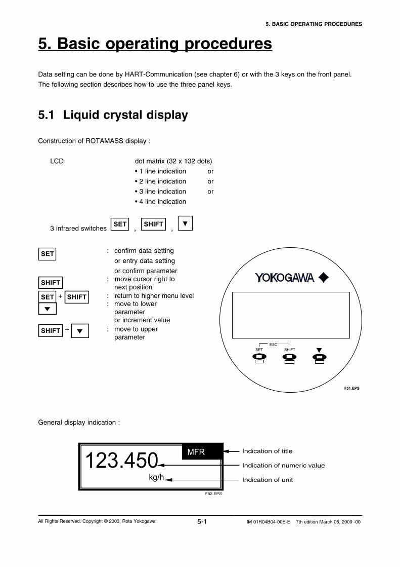
5.1 Liquid crystal display
Construction of ROTAMASS display :
LCD dot matrix (32 x 132 dots)
• 1 line indication or
• 2 line indication or
• 3 line indication or
• 4 line indication
3 infrared switches SET , SHIFT ,
SET : confirm data setting
or entry data setting
or confirm parameter
SHIFT : move cursor right to
next position
SET + SHIFT : return to higher menu level : move to lower
parameter or increment value
SHIFT + : move to upper parameter
F51.EPS
SET SHIFTESC
General display indication :
123.450 kg/h
MFR Indication of title
Indication of numeric value
Indication of unit
F52.EPS

5. BASIC OPERATING PROCEDURES
5-2IM 01R04B04-00E-E 7th edition March 06, 2009 -00 All Rights Reserved. Copyright © 2003, Rota Yokogawa
4 line indication
3 line indication
2 line indication.
1 line indication
+123.450 kg/h +12.3400 deg 0.99700 kg/l +12.3450 kg
MFR TMP DEN FTL
+123.450 kg/h
MFR
+123.450 kg/h
+12.3400 degC
MFR
TMP
+123.450 kg/h + 12.3400 degC 0.99700 kg/lro
MFR
TMP DEN
F53.EPS
The infrared switches operate as ON status by detecting the infrared ray reflection from a finger put over
the switches through the glass plate of the cover. Switches are just below the printed letters SET, SHIFT,
on the faceplate.
When you touch the switches, please note the following :
The switches may operate even when you do not touch the glass plate, if your fingers come near the
glass plate, so please touch the switches sliding with your finger from the lower part of the glass plate.
Also be sure not to touch more than one switch at one time by covering your other fingers over the
faceplate, unless you would like to push “SHIFT+SET” or "SHIFT+ .
You can increase the sensitivity of the infrared switches by sticking a white piece of tape on your finger tip.
Setting via the infrared buttons can be blocked via the HART protocol. If HART protocol is not used the
infrared buttons can be blocked by a black tape glued behind the window.
NOTE

5. BASIC OPERATING PROCEDURES
5-3 IM 01R04B04-00E-E 7th edition March 06, 2009 -00All Rights Reserved. Copyright © 2003, Rota Yokogawa
In the title indication the following abbreviations are used :
MASS FLOW RATE : MFR Additional with option /Cx : VOLUME FLOW RATE : VFR CONCENTRATION : CON FORWARD MASS TOTAL : FTM NET FLOW : NET REVERSE MASS TOTAL : RTM FORWARD NET TOTAL : FTN DIFFERENTIAL MASS TOTAL : DTM REVERSE NET TOTAL : RTN FORWARD VOLUME TOTAL : FTV DIFFERENTIAL NET TOTAL : DTN REVERSE VOLUME TOTAL : RTV DIFFERENTIAL VOLUME TOTAL : DTV DENSITY : DEN TEMPERATURE : TMP FORWARD ENERGY TOTAL : FTE VELOCITY : VEL
Number of figures :
totalizer ≤ 999999 : 1 sign + 6 figures (e.g. +123456) totalizer ≤ 9999999 : 1 sign + 7 figures (e.g. +1234567) totalizer > 9999999 : Exponential view (e.g. +1.23E12) measured value : 7 figures + 1 sign (e.g. +1234567) or 6 figures + 1 sign + 1 decimal point (e.g. +123.456) unit : 10 figures title : 3 figures
The contrast of the display can be adjusted with parameter
Detailed setup / Display Config / Disp contrast.
The indication period of the display can be adjusted with parameter
Detailed setup / Display Config / Disp period.
5.2 Display modes
The display can show the following indication modes :
1 Measuring mode Actual selected measuring values are shown
2 Parameter setting mode
2a Entry mode A confirmation, that setting via the infrared buttons should really happen
2b Parameter search mode Mode to search the parameter, which should be changed
2c Parameter select mode Mode to rewrite data. There are 4 types of data :- Select type (not blinking)- Numerical type (blinking)- Numerical type with sign (blinking)- Character type (blinking)
2d Data confirmation mode Mode to confirm new value of selected parameter
2e Data determination mode Parameter setting is completed
3 Alarm mode Alarm or Error Code is displayed alternating with measuring mode (2s Alarm / 4s Measure). Warnings are not displayed. Access to Warnings via Self Test/Status.
In measuring mode the actual measured values according the display select parameters are indicated as
shown in chapter 5.1. How to set display settings see chapter 5.4.
Parameter setting mode is described in chapter 5.3.
The language of the parameter setting mode can be selected in parameter
Language / or Detailed setup / Display config / language .
English, German or French can be selected.

5. BASIC OPERATING PROCEDURES
5-4IM 01R04B04-00E-E 7th edition March 06, 2009 -00 All Rights Reserved. Copyright © 2003, Rota Yokogawa
5.3 Setting via keys
The three keys SET
, SHIFT
, are used to set parameters via display menu.
The following flowchart shows how to reach the modes by using the keys :
Chapter 7.2 shows the display parameter list and chapter 7.3 shows the parameter tree.
Measuring mode
SET > 2s
Entry mode *) SHIFT+SET
Indicate "Setting enable?"
SET
Parameter search mode **)∇ downwards SHIFT+SETSHIFT +∇ upwards in main menuSET lower layerSHIFT+SET upper layer
SET
Parameter select mode **)Input data:
SHIFT + SET ∇ scroll down or increment numberSHIFT + ∇ scroll upSHIFT shift Cursor rightSET set Parameter SHIFT+SET to parameter search
SET
SHIFT + SET Data confirmation mode **)Data blinking
SET
after 2s Data determination modeNo blinking
*) Back to measuring mode if no key is pressed within 10s.**) Back to measuring mode if no key is pressed within 60s.
F54.EPS
IMPORTANT
IMPORTANT
The infrared keys can be locked via HART by Hot Key / Key Status.
Depending on parameter setting, only relating parameters are visible in the menu. E.g., if Pulse/Stat 1
select is set to Pulse, the parameters concerning status out 1 (SO1) do not appear in the menu.
Such dependences are described later in the concerning chapters.

5. BASIC OPERATING PROCEDURES
5-5 IM 01R04B04-00E-E 7th edition March 06, 2009 -00All Rights Reserved. Copyright © 2003, Rota Yokogawa
5.4 Examples of parameter settings via keys5.4.1 Display configuration, set volume flow to line 1
123.450 kg/h 0.99700 kg/l 12.3400 degC 12.3450 kg
MFR DEN TMP FTL
SET> 2s
Setting Enable?
Main Menu Language Process variables
Diag/Service
Main Menu Basic Setup
Detailed Setup Review device info
SET
SET
Basic Setup Tag Long Tag
Display config
Basic Setup Display Config
Mass flow Density
2x
Display config Display select 1 Display select 2
Display select 3
SET
Display
Mass flo
Display select 1 Mass flow
Volume flow Density
select
2x SET 3x SHIFT + SET
12.3400 Cum/h 0.99700 kg/l 12.3400 degC 12.3450 kg
VFR DEN TEMP FTL
3x
Display select 1 Mass flow
wVolume flow
SET
DensityTemperatureF-TotalR-TotalD-Total
F55.EPS

5. BASIC OPERATING PROCEDURES
5-6IM 01R04B04-00E-E 7th edition March 06, 2009 -00 All Rights Reserved. Copyright © 2003, Rota Yokogawa
5.4.2 Setting Temperature 20-120°C to Analog Output 2
MFR DEN TMP FTL
SET > 2s
Setting Enable?
Main Menu Language Process variables
Diag/Service
Main Menu Basic Setup
Detailed Setup Review device info
SET
SET
Basic Setup Tag Long Tag
Display config
Basic Setup Temperature
Analog 1 select Analog 2 select
5x
Temperature Temperature unit Temperature LRV
Temperature URV
SET
Temperature Temperature LRV Temperature URV Temperature damping
SET
Temperature LRV 000.00 degC 000.00 degC
SHIFT and
Temperature LRV 000.00 degC 020.00 degC
2x SET
Temperature Temperature URV
Temperature damping
Temperature Temperature LRV Temperature URV Temperature damping
F56.EPS
3x
123.450 kg/h 0.99700 kg/l 12.3400 degC 12.3450 kg

5. BASIC OPERATING PROCEDURES
5-7 IM 01R04B04-00E-E 7th edition March 06, 2009 -00All Rights Reserved. Copyright © 2003, Rota Yokogawa
2x SET
2x
SET
Analog 2 select Density
Density Temperature
2x SET
Basic Setup Analog 2 select
Pulse/Status out 1 Pulse/Status out 2
SET
Temperature URV 100.00 degC 000.00 degC
SHIFT and
Temperature URV 100.00 degC 120.00 degC
Basic Setup Temperature
Analog 1 select Analog 2 select
Analog 2 select Density
Temperature
Basic Setup Analog 2 select
Pulse/Status out 1 Pulse/Status out 2
SHIFT + SET, SHIFT + SET
MFR DEN TMP FTL
F57.EPS
Temperature Temperature URV
Temperature damping
SHIFT + SET
123.450 kg/h 0.99700 kg/l 12.3400 degC 12.3450 kg

5. BASIC OPERATING PROCEDURES
5-8IM 01R04B04-00E-E 7th edition March 06, 2009 -00 All Rights Reserved. Copyright © 2003, Rota Yokogawa
5.5 Setting parameters in converter with option /NCIf remote converter RCCF31 / RCCR31 was ordered with option /NC (no combination), the customer must
set the parameters of the connected detector by himself.
In parameter Detailed Setup / Sensor model the sensor model must be selected. Then, the sensor model
depending parameters are set automatically to default value :
Qnom, Mass flow unit, Mass flow LRV, Mass flow URV, Vol flow unit, Vol flow LRV, Vol flow URV, Autozero
range, Autozero fluctuation range.
In parameter Detailed Setup / Sensor constants the sensor constants from calibration certificate must be set.
If material of wetted parts is HC see instruction TI 01R04B04-03E-E attached to the converter.
In Parameter Basic setup / Tag or Basic setup / Long tag the tag number must be set if necessary.
Because the real Factory Zero Value and Autozero Fluctuation are not set, warnings W06 or W07 may
appear after autozero. These warnings can be ignored.
CAUTION

5. BASIC OPERATING PROCEDURES
5-9 IM 01R04B04-00E-E 7th edition March 06, 2009 -00All Rights Reserved. Copyright © 2003, Rota Yokogawa
After the flow meter is installed into the process pipe work, set up the parameter corresponding to calibration certificate (generally set up in the factory) and perform the pre-operation zero adjustment.
Zero adjustment is required before beginning operation in order to obtain the output signals are accurately proportional to the flow. Zero adjustment is performed to set the instrument to 0% when the flow rate is 0.
- Stop flow before starting autozero. - During autozero time - Analog outputs are fixed to 4 mA - Pulse outputs are fixed to zero. - Totalizer stops counting. - Display switches do not work. - In HART communication write- and exe-commands are not accepted.
- Status input does not work
Following procedure should be executed after installation but before starting measurement to get best measuring results: - Flush the meter with the fluid under process conditions.Flush the meter with the fluid under process conditions. - Stop flow, the best way is closing valves upstream and downstream.Stop flow, the best way is closing valves upstream and downstream. - Wait 2 minutes in which density, temperature and pressure should stabilize.Wait 2 minutes in which density, temperature and pressure should stabilize. - Density check: • for measurement of liquids control via expected medium density reading that the measuringfor measurement of liquids control via expected medium density reading that the measuring
tubes are gas free (density not lower than expected. Do not forget to insert the process pressure and pressure unit for the pressure compensation via Detailed Setup / Config Fld vars / Dens).
• for measurement of gases there is no possibility to check the density reading as the densityfor measurement of gases there is no possibility to check the density reading as the density value of gases is lower than 0.3 kg/l and the ROTAMASS switches automatically to 0 kg/l, see chapter 7.7. - Perform Autozero.Perform Autozero. - Store the Autozero value in Autozero History if required. (Only if you enter the date the values willStore the Autozero value in Autozero History if required. (Only if you enter the date the values will be stored). - Flow measurement can start.Flow measurement can start.
For setting a proper Autozero the conditions have to be well defined. Under certain circumstances it is recommended not to perform Autozero but use the Autozero value set during flow calibration in the factory: - zero flow condition cannot be guarantied while valves may be not tight - two or multi phase medium whether the phases separates under no flow condition - two phase medium whether there is gas contained in the fluid phase or liquid particles in the gas phase
ROTAMASS incorporates two measuring tubes which vibrates at a resonance frequency between 100 Hz and 200 Hz. Under certain circumstances there is a similar resonance frequency in the pipe work or fixture which might be excited. In this case high zero fluctuation may occur and Autozero value can’t be executed properly. Changes in the mechanical support of the detector should be done to decouple the detector from the vibrating structures.
5.6 Zero adjustment (Autozero)
IMPORTANT
IMPORTANT
CAUTION
WARNING

5. BASIC OPERATING PROCEDURES
5-10IM 01R04B04-00E-E 7th edition March 06, 2009 -00 All Rights Reserved. Copyright © 2003, Rota Yokogawa
How to perform Autozero via keys :
MFR DEN TMP FTL
SET> 2sSetting Enable?
Main Menu Language Process variables
Diag/Service
Main Menu Diag/Service
Basic Setup Detailed Setup
SET
2x
Diag/Service Autozero check
Autozero Output trim
2x
Diag/Service Autozero
Output trim
SET Diag/Service
F58.EPS
Autozero checkInput/Output testSelftest/Status
SET AutozeroMass flow Zero tuning
Autozero Auto zero exe
Autozero value
SET Auto zero exe Not execute
Execute
2x
SET Autozero tuning
Inhibit Inhibit
Enable
2x SETAutozeroMass flow Zero tuning Auto zero time
Auto zero exe
Autozero tuning
Enable
2x SET
Autozero tuning Enable
Inhibit
123.450 kg/h 0.99700 kg/l 12.3400 degC 12.3450 kg

5. BASIC OPERATING PROCEDURES
5-11 IM 01R04B04-00E-E 7th edition March 06, 2009 -00All Rights Reserved. Copyright © 2003, Rota Yokogawa
Reading Autozero history (see also chapter 7.23) :
MFR DEN TMP FTL
SET> 2s Setting Enable?
Main Menu Language Process variables
Diag/Service
Main Menu Diag/Service
Basic Setup Detailed Setup
SET
2x
Diag/Service Autozero check
Autozero Output trim
2x
SET Autozero check Autozero history Autozero initial
Autozero range
Autozero history 05/05/2003
10/06/2003
SET
AZ hist : 05/05/2003+ 0000.00 kg/h+ 00.0000 kg/l+ 0030.00 degC
SET Diag/Service
F59.EPS
Autozero checkInput/Output testSelftest/Status
SET
15/07/2004
SHIFT+ SET
Autozero05/05/2003
10/06/200315/07/2004
123.450 kg/h 0.99700 kg/l 12.3400 degC 12.3450 kg
Autozero
Auto zero Exe XXX.XXkg/h
2x SET
Autozero Autozero exe Doing Autozero 180sec
After 30s /180s
Auto zero Exe Execute
SET
Set date with SHIFT+ . Then press 2x SET Autozero data are written in Autozero
history.
Autozero
Date (DD/MM/YYYY)00/00/2000
F58a.EPS
3x SHIFT + SET Measuring mode

5. BASIC OPERATING PROCEDURES
5-12IM 01R04B04-00E-E 7th edition March 06, 2009 -00 All Rights Reserved. Copyright © 2003, Rota Yokogawa
Blank Page

6. OPERATION VIA HART
6-1 IM 01R04B04-00E-E 7th edition March 06, 2009 -00All Rights Reserved. Copyright © 2003, Rota Yokogawa
6. Operation via HART
6.1 Conditions of Communication LineThe HART-communicator can communicate with the ROTAMASS RCCT_F3 from the control room, the
ROTAMASS site or any other wiring termination point in the loop, provided there is a minimum load
resistance of 230Ω between the connection and the instrument. To communicate, it must be connected in
parallel with the ROTAMASS RCCT_F3, the connections are not polarized. The figure below shows the wiring
connections for direct interface at the ROTAMASS RCCT_F3.
Specifications of communication line :
Load resistance : 230 to 600 Ω, for multidrop mode see figure below
Minimum cable size : 24 AWG (0.51 mm diameter)
Cable type : single pair shielded or multiple pair with overall shield
Maximum twisted pair length : 6,500 ft (2,000 m)
Maximum multiple twisted pair length : 3,200 ft (1,000 m)
Use the following formula to determine cable length for a specific application :
L = (65x106) / (RxC) - (Ci + 10,000) /C)
Where : L = length in feet or meters
R = resistance in ohms, current sense resistance
C = cable capacitance in pF/ft or pF/m
Ci = 50,000 pF
Load resistance and quantity of devices in multidrop mode :
800700600500400300200100 0
1 2 3 4 5 6 7 8 9 10 11 12 13 14 15
Loadresistance [ Ω ]
Quantity of connected field devicesF62.EPS
230
571500
333 307 285 266
400444363
RCCT_F3
HARTCommunicator
HARTCommunicator
HARTCommunicator
Intermediateterminals
4 to 20mA DCsignal trans-mission line
Receivinginstrument
Terminal board
Control room
F61.EPS

6. OPERATION VIA HART
6-2IM 01R04B04-00E-E 7th edition March 06, 2009 -00 All Rights Reserved. Copyright © 2003, Rota Yokogawa
6.2 Communication via FieldMateFieldMate is a PC-based flexible field device management tool from Yokogawa.
Features:
- Instant device recognition upon connection for HART, FF, Profibus and BRAIN devices
- Support of both FDT/DTM and EDDL technologies
- Database support for offline maintenance
- Full history and audit trail
- Synchronization with PRM
The segment viewer will automatically scan the bus and will list your devices:
The FDT certified RotaMASS DTM will make it easy to configure and maintain your device:
All Yokogawa device DTM’s can be downloaded for free from the web site:
http://downloads.yokogawa-europe.com

6. OPERATION VIA HART
6-3 IM 01R04B04-00E-E 7th edition March 06, 2009 -00All Rights Reserved. Copyright © 2003, Rota Yokogawa
6.3 Communication via HART CommunicatorKeys and functions of HHT 375:
Touch screen display
HART communicationterminals
Enter key
Function key
Alphanumeric keypad
On/Off key
Navigation keys(4 arrow keys)
Tab key
The HART communicator automatically searches for ROTAMASS RCCT_F3 on the 4-20mA loop, when it is
turned on. When HART communicator is connected to RCCT_F3, it displays the online menu.
(If RCCT_F3 is not found, it displays “No device found. Press OK…”. Press OK ´F4´ function key and the
main menu appears. Please retry after confirming the connection with RCCT_F3).If there is no device specific DD installed in the HHT375 (RCCT_F3, Dev v1, DD v1), the functionality of the HART Menu as listed in chapter 7.4 is not total supported.In this case the HHT375 works in the “Generic Mode”, which allows configuring the ROTAMASS with limited functionality.For upgrading your HHT375 please use "Easy Upgrade" programming utility which is available from
EMERSON.
Online Menu SummaryNo. Display item Contents
1 Device Setup Set parameters for ROTAMASS
2 PV Display process value in engineering unit
3 PV AO Display analog output in mA
4 Review Review parameters for ROTAMASS
5 Service Not open
6. OPERATION VIA HART
6-4IM 01R04B04-00E-E 7th edition March 06, 2009 -00 All Rights Reserved. Copyright © 2003, Rota Yokogawa
The menu tree in chapter 7.3 shows the configuration of the online menu, which is needed for the operation
with HART communicator. Select ´Device Setup´ to call up the desired item as follows:
There are two choices to select the desired menu item:
1. Use the ↓ or ↑ key to select the desired item, and then press the → key.
2. Press the number key displayed for the desired item.
To return to the previous display, press the ← key, EXIT (F4), ESC(F3) or ABORT(F3).
Entering, setting and sending data:
The data, which is input with the keys is set in the HART-communicator by pressing ENTER(F4). Then,
by pressing SEND(F2), the data is sent to RCCT_F3. Note that the data is not sent to ROTAMASS if
SEND(F2) is not pressed. All the data set with the HART-communicator is held in memory unless power is
turned off, so all data can be send to RCCT_F3 in one lot.
IMPORTANT Parameter setting on the display with the infrared keys is prohibited during HART communication.
IMPORTANT Do not turn power off just after HART-Communicator settings (sending) have been made. If ROTAMASS
is turned off less than 30 seconds after parameters have been set, the set data will not be stored and the
data returns to previous settings.
6.4 Unique functions of HART CommunicatorCheck on communication error:
When over run error, framing error, parity error or buffer overflow error is detected, the data including the
information of errors is returned, and the error message is indicated on HHT.
Time recording:
Online → Device setup → Detailed setup → Device information → Date
Month and day can be set in a number of 2 figures, Year in 4 figures.
Multi-drop communication:
Field devices in multi-drop mode refer to the connection of several field devices on a
communication single line. Up to 15 field devices can be connected when set in the multi-drop mode.
To activate multi-drop communication, the field device address must be changed to a number from 1 to 15.
This change deactivates the 4 to 20 mA output and turns it to 4 mA.
Online → Device setup→ Detailed setup → HART Communication → Poll address
Write protect:
Write protect function is provided to inhibit parameter change. That becomes active by
entering a password in “New password”. Write protect status is released for 10 minutes by entering the
password in “Enable wrt 10 min”.
Setting the password:
Hotkey → New password
Enter new password to change state of write.
Hotkey → Enable wrt 10 min
“Enable Write” release write protect status for 10 minutes.
6. OPERATION VIA HART
6-5 IM 01R04B04-00E-E 7th edition March 06, 2009 -00All Rights Reserved. Copyright © 2003, Rota Yokogawa
While write protect status is released, enter a new password twice, within 30 sec in “New Password”.
It will not be possible to set a new password when 10 minutes have elapsed.
If a parameter, which is write enabled , is changed while the device is in “Enable wrt 10min”, release time is
extended for further 10 minutes.
NOTE • When the write protect function is active (its menu bar shows “Yes”), data setting changes in all parameters
of RCCT_F3 are inhibited and cannot be changed using the HART communicator. Also the setting via the
infrared pushbuttons is prohibited.
• If 8 characters are input as “space”, the Write protect function is in release status irrespective of time.
• If both RCCT_F3 and HART Communicator power off and on again within 10 minutes after releasing of
write protect status, “Enable Write” becomes unavailable.
Software seal :
The “Software seal” menu is reserved as evidence so that user is able to confirm whether the Joker
password is used or not. This evidence is saved.
Hotkey → Software seal
The first indication in Software seal menu is ´keep´.
After the joker password setting it shows ´break´.
After setting a new password and release via “Enable wrt 10 min”, the Software seal shows “keep” again.
Key Status :
Enable: Infrared keys are activated. Inhibit: Infrared keys are deactivated.
Master Reset :Default : all parameters set to default except board constants, calibration constants, detector depending parameter and Concentration measuring settings in service menu.
6.5 Transmitting device variables via HARTWhile current output 1 is connected to a HART master it is possible to transmit up to 4 device variables
named primary (PV), secondary (SV), tertiary (TV) and quaternary variable (QV). To select which measure-
ment value will be transmitted in which place there are basically two ways.
• Setting via output configuration
The 4 device variables are linked to the settings of the corresponding output according to the table:
Device variable Corresponding output (not option /KF2) Corresponding output (option /KF2)
PV Current output 1 (Iout 1) Current output 1 (Iout 1)
SV Current output 2 (Iout 2) Not available
TV Pulse output 1 (Pout) Pulse output 1 (Pout)
QV Pulse output 2 (Sout) Not available
The unit, in which the device variable is transmitted, is taken from the unit of the corresponding measure-
ment value as shown on the display. To change the order of the device variables, the output configuration
has to be changed.
• Setting via HART
For setting the device variables there are the two common practice commands #51 (assignment of device
variables) and #53 (unit of device variables). Neither in the DD nor in the DTM there is a menu for these
settings. These commands are typically used by other HART devices like multiplexers.
Since the device variables are linked to the output configuration sending one of this commands will change
the output configuration of ROTAMASS!

6. OPERATION VIA HART
6-6IM 01R04B04-00E-E 7th edition March 06, 2009 -00 All Rights Reserved. Copyright © 2003, Rota Yokogawa
6.6 Hardware Write ProtectIf software write protection via password is not suitable to protect the access to the converter, a hardware
write protection can be set:
• Open the cover of the converter.
• Unscrew the 4 screws of the display and move the display aside.
• Set the jumper on JP1 of CPU-board as shown in the following picture.
Screw the display and close the cover.
The hardware write protection is prior to any other write protection, and cannot be released by HART or
other software means.
Enable Protect F64.EPS
CPU Board
Cable to display
JP1

7. PARAMETER DESCRIPTION
7-1 IM 01R04B04-00E-E 7th edition March 06, 2009 -00All Rights Reserved. Copyright © 2003, Rota Yokogawa
7. Parameter description7.1 Overview
The table below shows an overview of functions of ROTAMASS RCCT3/RCCF31/RCCR31. In brackets the related chapters in this manual are indicated.
Hot k
ey
(6.3)
W
rite P
rotec
t
HART
Enab
le wr
t 10
min.
HAR
T Ne
w Pa
sswo
rd
HART
Softw
are s
eal
HART
Key S
tatus
HART
Hard
ware
Write
Pro
tect
(6.4)
Mass
flow
(7
.5)
Mas s
flow
unit
Mass
flow
forma
t Ma
ss flo
w LR
V Ma
ss flo
w UR
V Ma
ss flo
w da
mping
Ma
ss flo
w low
cut
Mass
flow
alm
1 sel
Mass
flow
alm
1 crit
Mass
flow
alm
2 sel
Mass
flow
alm
2 crit
MF fix
val s
el MF
fixed
value
Volum
e fl ow
(7
.6)
Vol fl
ow un
it Vo
l flow
form
at
Vol fl
ow LR
V Vo
l flow
URV
Vo
l flow
da
mping
Vo
l flow
lowc
ut
Vol fl
ow al
m 1
sel
Vol fl
ow al
m 1
crit
Vol fl
ow al
m 2
sel
Vol fl
ow al
m 2
crit
Dens
ity
(7.7)
De
nsity
unit
Dens
ity fo
rmat
De
nsity
LRV
Dens
ity U
RV
Dens
ity
damp
ing
Dens
ity lo
wcut
De
nsity
alm
1 se
l De
nsity
alm
1 cri
t De
nsity
alm
2 se
l De
nsity
alm
2 cri
t De
nsity
fix va
l se
l Re
feren
ce
den
sity
Temp
eratu
re
(7.8)
Te
mper
ature
un
it Te
mper
ature
for
mat
Temp
eratu
re
LRV
Temp
eratu
re
URV
Temp
eratu
re
damp
ing
Temp
eratu
re
alm 1
sel
Temp
eratu
re
alm 1
crit
Temp
eratu
re
alm 2
sel
Temp
eratu
re
alm 2
crit
Temp
eratu
re
fix va
l sele
ct Te
mper
ature
fix
ed va
lue
Temp
eratu
re
gain
adjus
t
Stati
c pre
ssur
eco
ntrol
Analo
g ou
tput 1
(7.10
) An
alog 1
sele c
t An
alog 1
ala r
m ou
t An
alog 1
low
LMT
Analo
g 1 hi
gh
LMT
Analo
g ou
tput 2
(7.11
)An
alog 2
sele c
t An
alog 2
ala r
m ou
t An
alog 2
low
LMT
Analo
g 2 hi
gh
LMT
Pulse
/Stat
us
out 1
(7.12
) Pu
lse/S
tat 1
selec
t Pu
lse 1
selec
t Pu
lse 1
unit
Pulse
1 ra
te
Pulse
1 ac
tive
mode
Pu
lse 1
width
Pu
lse1 a
t ala r
m
SO1 f
uncti
on
SO1 a
ctive
mo
de
Pulse
/Stat
us
out 2
(7.13
) Pu
lse/S
tat 2
selec
t Pu
lse 2
selec
t Pu
lse 2
unit
Pulse
2 ra
te
Pulse
2 ac
tive
mode
Pu
lse 2
width
Pu
lse2 a
t ala r
m
SO2 f
uncti
on
SO2 a
ctive
mo
de
Statu
s inp
ut
(7.14
) SI
func
tion
SI ac
tive m
ode
Total
izer
(7.15
) To
tal sw
itch
se
le ct
To
tal un
it To
tal sw
itch
Total
a t a
larm
To
tal re
set c
ntrl
Total
rese
t
Disp
lay
(5)
Disp
lay co
nfig
Lang
uage
Di
sp.co
ntras
t Di
sp.pe
ri od
Key S
tatus
Diag
/Ser
vice
(8
) Se
lf te s
t /stat
us
(8.3)
Inp
ut/Ou
tput
Test
(8
.4)
Autoz
ero c
heck
(5
.6)
Auto z
ero
(7
.23)
Outpu
t trim
(8
.5)
Histo
ry ov
er-
view
(8.2)
Er
ror h
istor
y (8
.2)
Spec
ial
func
tions
Flo
w dir
ectio
n (7
.16)
Conc
entra
tiom
meas
urem
ent
(7.17
)
Net fl
ow
(7.18
) Sl
ug de
tectio
n (7
.19)
Empty
pipe
de
tectio
n (7.2
0)
Corro
sion
detec
tion (
7.21)
Flu
id ma
x. Te
mp.
(7
.24)
Gas
meas
urem
ent
(7.25
)
Detec
tor da
ta
(7.22
) Se
nsor
mod
el Se
nsor
co
nstan
ts Se
nsor
S/N
Devic
e data
Di
stribu
t or
Tag
Desc
riptor
Me
ssag
e Da
te De
v id
Unive
rsal re
v Fld
dev r
ev
Softw
are r
ev
Hard
ware
rev
HART
data
(6
.3 )
Poll a
ddre
ss
Num
req
prea
ms
Num
resp
pr
eams
Ma
ster r
ese t
T71.EPS
Devic
e S/W
ve
rsion
Devic
e S/W
da
te
Veloc
ity(7
.9)Ve
locity
unit
Dens
ity
offse
t

7. PARAMETER DESCRIPTION
7-2IM 01R04B04-00E-E 7th edition March 06, 2009 -00 All Rights Reserved. Copyright © 2003, Rota Yokogawa
Differences between Display and HART setting
The ROTAMASS software is continuously improved. This leads to functionalities, which are differ-ent in HART (DD version 0301) and display setting (software version from 1.07.21)The following functions have only effect via display :1. Display select 2 / None *)2. Display select 3 / None *)
*) HART shows "Unknown enumerator" if a parameter was selected via display which is unknown
in HART.
7.2 Parameter listR : read Reset
W: write
Parameter Data form
Data range Dec. Point
Unit
Exe : execute
Master Power on
Default
No Write protect Select
Yes
- - R/W
-
Enable WRT 10 min Acc. to HART - - R/W X Disable
New Password ASCII 8 characters - - R/W X Space
Break Software Seal Select
Keep
- - R/W
-
Not Execute Master Reset Select
Execute
- - EXE
X
Not Execute
Key Status Select Enable X
Inhibit
- - R/W
X Enable
English X
German
Language Select
French
- - R/W
English
Mass Flow Decimal - 0 to 5 Mass flow unit R - -
Volume Flow Decimal - 0 to 5 Vol flow unit R - -
Density Decimal - 0 to 5 Density unit R - -
Temperature Decimal - 0 to 5 Temperature unit R - -
F-Total mass Decimal - Auto Total unit mass R - -
F-Total vol Decimal Auto Total unit volume R -
F-Total net Decimal Auto Total unit net R -
Concentration meas Decimal - 0 to 5 Customer specific
R - -
Net flow Decimal - 0 to 5 Mass flow unit R - -
Analog output 1 Decimal - as sel. Var.
as sel. Var. R - -
Analog output 1 % Decimal - 2 % R - -
Analog output 1 mA Decimal - 2 mA R - -
R-Total mass Decimal - Auto Total unit mass R -
D-Total mass Decimal - Auto Total unit mass R -
-
-
-
-
R-Total vol Decimal Auto Total unit volume R -- -
D-Total vol Decimal Auto Total unit volume R -- -
R-Total net Decimal Auto Total unit net R -
D-Total net Decimal Auto Total unit net R -
-
-
-
-
-
-
F-Total energy Decimal Auto Total unit energy R - --
Velocity Decimal Auto Velocity unit R - --

7. PARAMETER DESCRIPTION
7-3 IM 01R04B04-00E-E 7th edition March 06, 2009 -00All Rights Reserved. Copyright © 2003, Rota Yokogawa
Not Execute Self Test Select
Execute
- - R/W
X Not Execute
Status ASCII Results of last self test
- - R - -
Hist Overview ord ASCII - - - R - -
Hist Overview abs ASCII - - - R - -
Error History ASCII - - - R - -
Analog output 1(Test ) Decimal 2.4 to 21.5 2 mA W X X 4.0
Analog output 2(Test ) Decimal 2.4 to 21.5 2 mA W X X 4.0
Pulse output 1 (Test ) Decimal 0 to 10000 1 Hz W X X 1000.0
On Active X Status output 1 (Test ) Select
Off Active
- - W
X On Active
Pulse output 2 (Test ) Decimal 0 to 10000 1 Hz W X X 1000.0
On Active X Status output 2 (Test ) Select
Off Active
- - W
X On Active
Status input (Test ) ASCII Status SI - - W - -
Inhibit X Autozero tuning Select
Enable
- - R/W
X Inhibit
3 min. X Autozero Time Select
30 s
- - R/W
X 3 min.
Not Execute X Autozero Exe Select - - Exe X Not Execute
000.000
- -
- -
- -
- -
4mA - 0
Output Trim AO 2 trim 4mA
Decimal Acc. To HART - - R/W - 0
Output Trim AO 1 trim 20mA
Decimal Acc. To HART - - R/W - 0
Output Trim AO 2 trim 20mA
Decimal Acc. To HART - - R/W - 0
Tag ASCII 8 characters - - R/W Space
Long Tag ASCII 22 characters - - R/W Space
Execute
Autozero Value Decimal depends on size 3 R X
Autozero History ASCII - - - R
Autozero initial Decimal depends on size 3 R
Autozero range Decimal depends on size 3 R
Autozero fluctuation Decimal depends on size 3 R
Output Trim AO 1 trim Decimal Acc. To HART - - R/W
kg/h
kg/h
kg/h
kg/h
Analog output 2 Decimal - as sel. Var.
as sel. Var. R - -
Analog output 2 % Decimal - 2 % R - -
Analog output 2 mA Decimal - 2 mA R - -
Pulse output 1 Decimal - 1 Hz R - -
Status output 1 ASCII - - - R - -
Pulse output 2 Decimal - 1 Hz R - -
Status output 2 ASCII - - - R - -
View input ASCII - - - R - -
Total reset cntrl Select Inhibit X
Enable
- - R/W
X Inhibit
Total reset Select Not Execute X
Execute
- - R/W
X Not Execute

7. PARAMETER DESCRIPTION
7-4IM 01R04B04-00E-E 7th edition March 06, 2009 -00 All Rights Reserved. Copyright © 2003, Rota Yokogawa
Disp select 3 Select - - R/W X Temperature
Disp select 2 Select - - R/W X Density
Disp select 1 Select - - R/W X Mass Flow
Mass flow
Volume flow
Density
Temperature
F-Total mass
R-Total mass
D-Total mass
F-Total volume
R-Total volume
D-Total volume
F-Total net
R-Total net
D-Total net
Concentration
meas
Net flow
F-Total energy
Velocity
Mass flow
Volume flow
Density
Temperature
F-Total mass
R-Total mass
D-Total mass
F-Total volume
R-Total volume
D-Total volume
F-Total net
R-Total net
D-Total net
Concentration
meas
Net flow
F-Total energy
Velocity
None
Mass flow
Volume flow
Density
Temperature
F-Total mass
R-Total mass
D-Total mass
F-Total volume
R-Total volume
D-Total volume
F-Total net
R-Total net
D-Total net
Concentration
meas
Net flow
F-Total energy
Velocity
None

7. PARAMETER DESCRIPTION
7-5 IM 01R04B04-00E-E 7th edition March 06, 2009 -00All Rights Reserved. Copyright © 2003, Rota Yokogawa
Disp select 4 Select - - R/W X F-Total mass
Disp Contrast Decimal -5 …+5 - - R/W 0
0.5 s X
1.0 s
Disp Period Select
2.0 s
- Sec. R/W
1.0 s
Forward X Flow direction Select
Reverse
- - R/W
Forward
g/s
g/min
g/h
kg/s
kg/min
kg/h
t/min
Mass flow unit Select
t/h
- - R/W
RCCS30 ... 33
Kg/h RCCS34 …39
t/h
xxxxxxx
xxxxx.X
xxxx.XX
xxx.XXX
xx.XXXX
Mass flow format Select
x.XXXXX
- - R/W
xxxx.XX
Mass flow LRV Decimal -Qmax to Qmax 0 to 5 Mass flow unit R/W 0
Mass flow URV Decimal 0 to Qmax 0 to 5 Mass flow unit R/W Qnom
Mass flow damping Decimal 0.1 to 200 1 Sec. R/W X 3
Mass flow lowcut Decimal 0 to 10% of Qmax 0 to 5 Mass flow unit R/W 0
No Function X
More Than
Mass flow alm1 sel Select
Less Than
- - R/W
No Function
Mass flow alm1 crit Decimal -110% to 110% of URV
0 to 5 Mass flow unit R/W X 0
Mass flow
Volume flow
Density
Temperature
F-Total mass
R-Total mass
D-Total mass
F-Total volume
R-Total volume
D-Total volume
F-Total net
R-Total net
D-Total net
Concentration
meas
Net flow
F-Total energy
Velocity
None

7. PARAMETER DESCRIPTION
7-6IM 01R04B04-00E-E 7th edition March 06, 2009 -00 All Rights Reserved. Copyright © 2003, Rota Yokogawa
No Function X
More Than
Mass flow alm 2 sel Select
Less Than
- - R/W
No Function
Mass flow alm2 crit Decimal -110% to 110% of URV
0 to 5 Mass flow unit R/W X 0
Inhibit X Mass flow fix val sel Select
Enable
- - R/W
Inhibit
Mass flow fixed val Decimal 0 to Qnom 0 to 5 Mass flow unit R/W X 0
Cucm/sCucm/minCucm/hl/sl/minl/hCum/sCum/minCum/hgal/sgal/mingal/hCuft/sCuft/minCuft/hbbl/sbbl/minbbl/hbbl/dImpgal/sImpgal/minImpgal/hNl/sNl/minNl/hNcum/sNcum/minNcum/hSl/sSl/minSl/hScuft/sScuft/minScuft/hScum/sScum/minScum/h
Vol flow unit Select
- - R/W Cum/h
xxxxxxx
xxxxx.X
xxxx.XX
xxx.XXX
xx.XXXX
Vol flow format Select
x.XXXXX
- - R/W
xxxx.XX
Vol flow LRV Decimal -Qvmax to Qvmax 0 to 5 Vol flow unit R/W 0
Vol flow URV Decimal 0 to Qvmax 0 to 5 Vol flow unit R/W
Vol flow Damping Decimal 0.1 to 200 1 Sec. R/W X 3
Vol flow Lowcut Decimal 0 to 10% of Qvmax 0 to 5 Vol flow unit R/W X 0
No Function X
More Than
Vol flow alm 1 sel Select
Less Than
- - R/W
No Function
Qvnom
Vol flow alm 1 crit Decimal -110% to 110% of URV
0 to 5 Vol flow unit R/W X 0
No Function X
More Than
Vol flow alm 2 sel Select
Less Than
- - R/W
No Function
Vol flow alm 2 crit Decimal -110% to 110% of URV
0 to 5 Vol flow unit R/W X 0

7. PARAMETER DESCRIPTION
7-7 IM 01R04B04-00E-E 7th edition March 06, 2009 -00All Rights Reserved. Copyright © 2003, Rota Yokogawa
g/ml
kg/l
kg/Cum
lb/gal
lb/Cuft
g/cc
°Bé hv
°Bé lt
°API
X
Density unit Select
- - R/W kg/l
xxxxxxx X
xxxxx.X
xxxx.XX
xxx.XXX
xx.XXXX
Density format Select
x.XXXXX
- - R/W
xx.XXXX
Density LRV Decimal 0 to 5 kg/l 0 to 5 Density Unit R/W X 0.0
Density URV Decimal 0 to 5 kg/l 0 to 5 Density Unit R/W X 1.5
Density damping Decimal 0.1 to 200 1 Sec R/W X 15.0
Density lowcut Decimal 0 to 110% of URV 0 to 5 Density Unit R/W X 0.0
No Function X
More Than
Density alm 1 sel Select
Less Than
- - R/W
No Function
Density alm 1 crit Decimal 0 to 5 kg/l 0 to 5 Density Unit R/W X LRV
No Function X
More Than
Density alm 2 sel Select
Less Than
- - R/W
No Function
Density alm 2 crit Decimal 0 to 5 kg/l 0 to 5 Density Unit R/W X URV
Inhibit X Density fix val sel Select
Enable
- - R/W
X Inhibit
Reference density Decimal 0 to 5 kg/l 0 to 5 Density Unit R/W X X 1.0
Pressure Decimal 0 to 400 2 bar R/W X X 0.0
degC X
degF
Temperature unit Select
K
- - R/W
degC
Xxxxxxx X
xxxxx.X
xxxx.XX
xxx.XXX
xx.XXXX
Temperature format Select
x.XXXXX
- - R/W
xxxxx.X
Temperature LRV Decimal Standard : -200 to 230 °C
0 to 5 Temperature unit R/W X 0.0
High Temp. : 0 to 400 °C
Temperature URV Decimal Standard : -200 to 230 °C
0 to 5 Temperature unit R/W X 150.0
High Temp. : 0 to 400 °C
Temperature damping Decimal 0.1 to 200 1 Sec R/W X 15.0
No Function X
More Than
Temp alm 1 sel Select
Less Than
- - R/W
No Function
Pressure Unit Select barpsi
- - R/W barX
Density offset Decimal --------- 0 to 2 g/l R/W X X 0.0

7. PARAMETER DESCRIPTION
7-8IM 01R04B04-00E-E 7th edition March 06, 2009 -00 All Rights Reserved. Copyright © 2003, Rota Yokogawa
No Function X
More Than
Temp alm 2 sel Select
Less Than
- - R/W
No Function
Temp alm 2 crit Decimal Standard : -200 to 230 °C
0 to 5 Temperature unit R/W X URV
High Temp. : 0 to 400 °C
Inhibit X Temp fix val select Select
Enable
- - R/W
X Inhibit
Temp fixed value Decimal Standard : -200 to 230 °C
1 Temperature unit R/W X X 30.0
High Temp. : 0 to 400 °C
Temp gain Decimal 0.8 … 1.2 3 - R/W 1.000
None
Mass flow
Volume flow
Density
Temperature
Concentration meas
Analog 1 select
Select
Netflow
- - R/W X Mass flow
<2.4mA X
<3.6mA
4.0mA
>21mA
>21.6mA
Hold
Analog 1 alarm out Select
Measured Value
- - R/W
<3.6mA
Analog 1 low LMT Decimal NAMUR: : 3.8 to 20.5 mA
2 mA R/W X
Not NAMUR : 2.4 to 21.6 mA
Analog 1 high LMT Decimal NAMUR : 3.8 to 20.5 mA
2 mA R/W X
21.6 mA
None
Mass flow
Volume flow
Density
Temperature
Concentration meas
Analog 2 select
Select
Netflow
- - R/W
X
Density
3.8 (Namur) ;2.4 (not Namur)
20.5 (Namur) ;21.6 (not Namur)
Temp alm 1 crit Decimal Standard : -200 to 200 °C
0 to 5 Temperature unit R/W X LRV
<2.4mA
<3.6mA
4.0mA
>21mA
>21.6mA
Hold
Analog 2 alarm out Select
Measured Value
- - R/W X <3.6mA
m/s XVelocity unit Select
ft/s
- - R/W m/s
Not NAMUR : 2.4 to

7. PARAMETER DESCRIPTION
7-9 IM 01R04B04-00E-E 7th edition March 06, 2009 -00All Rights Reserved. Copyright © 2003, Rota Yokogawa
Analog 2 low LMT Decimal 20.5 mA
2 mA R/W X 3.8 (Namur); 2.4 (Not Namur)
21.6 mA
Analog 2 high LMT Decimal 20.5 mA
2 mA R/W X 20.5 (Namur); 21.6 (Not Namur)
21.6 mA
Pulse X
Status out
Pulse/Stat 1 select Select
No Function
- - R/W
Pulse
None X
Mass forward
Mass reverse
Volume forward
Volume reverse
Mass flow
Volume flow
Density
Temperature
Concentrationmeas
Net forward
Net reverse
Pulse 1 select Select
Net flow
- - R/W
Mass forward
Hz
g/P
kg/P
t/P
lb/P
Cucm/P
l/P
Cum/P
gal/P
kgal/P
Cuft/P
bbl/P
Impgal/P
kImpgal/P
Nl/P
Ncum/P
Sl/P
Scuft/P
Scum/P
X
Pulse 1 unit Select - - R/W
kg/P
Pulse 1 rate Decimal 0 to 10000 0 Pulse 1 unit R/W X 1
On Active X Pulse 1 active mode Select
Off Active
- - R/W
On active
NAMUR : 3.8 to
Not NAMUR : 2.4 to
NAMUR : 3.8 to
Not NAMUR : 2.4 to

7. PARAMETER DESCRIPTION
7-10IM 01R04B04-00E-E 7th edition March 06, 2009 -00 All Rights Reserved. Copyright © 2003, Rota Yokogawa
0.05ms
0.1ms
0.5ms
1ms
5ms
10ms
50ms
Pulse 1 width Select
100ms
- - R/W
1ms
0P/0Hz X Pulse 1 at alarm Select
Measured Value
- - R/W
0P/0Hz
No Function X No Function
Flow - Direction
Total switch
Mass flow alm 1
Mass flow alm 2
Mass flow alm 1+2
Vol flow alm 1
Vol flow alm 2
Vol flow alm 1+2
Density alm 1
Density alm 2
Density alm 1+2
Temp alm 1
Temp alm 2
Temp alm 1+2 Concentr. meas alm 1
Concentr. meas alm 2
Concentr. meas alm 1+2
Net flow alm 1
Net flow alm 2
Net flow alm 1+2
Slug alarm
Empty alarm
SO 1 function Select
Corrosion alarm
- - R/W
On Active X SO 1 active mode Select
Off Active
- - R/W
On active
Pulse X
Status out
Pulse/Stat 2 select Select
No Function
- - R/W
Status out
500ms
1000ms
All alarms
Hold

7. PARAMETER DESCRIPTION
7-11 IM 01R04B04-00E-E 7th edition March 06, 2009 -00All Rights Reserved. Copyright © 2003, Rota Yokogawa
None X
Mass forward
Mass reverse
Volume forward
Volume reverse
Mass flow
Volume flow
Density
Temperature
Concentration meas
Pulse 2 select Select
Net forward
- - R/W
Density
X
Pulse 2 unit Select - - R/W
Hz
Net reverse
Net flow
Pulse 2 rate Decimal 0 to 2000 0 Pulse 2 unit R/W X 1000
On Active X Pulse 2 active mode Select
Off Active
- - R/W
On active
Pulse 2 width Select - - R/W
1ms
X Pulse 2 at alarm Select
Measured Value
- - R/W
0.05ms
0.1ms
0.5ms
1ms
5ms
10ms
50ms
100ms
500ms
1000ms
Hz
g/P
kg/P
t/P
lb/P
Cucum/P
l/P
Cum/P
gal/P
kgal/P
Cuft/P
bbl/P
Impgal/P
kImpgal/P
0P/0Hz 0P/0Hz
Hold
Nl/P
Ncum/P
Sl/P
Scuft/P
Scum/P

7. PARAMETER DESCRIPTION
7-12IM 01R04B04-00E-E 7th edition March 06, 2009 -00 All Rights Reserved. Copyright © 2003, Rota Yokogawa
No Function X
Flow - Direction
Total switch
Mass flow alm 1
Mass flow alm 2
Mass flow alm 1+2
Vol flow alm 1
Vol flow alm 2
Vol flow alm 1+2
Density alm 1
Density alm 2
Density alm 1+2
Temp alm 1
Temp alm 2
Temp alm 1+2
Concentr. measalm 2
Concentr. measalm 2
Concentr. measalm 1+2
Net flow alm 1
Net flow alm 2
Net flow alm 1+2
Slug alarm
Empty alarm
SO 2 function Select
Corrosion alarm
- - R/W
No Function
On Active X SO 2 active mode Select
Off Active
- - R/W
On active
No Function X
Autozero
Total reset
SI function Select
0% Signal lock
- - R/W
No Function
On Active X SI active mode Select
Off Active
- - R/W
On active
Mass X
Volume
Total switch select Select
Net
- - R/W
Mass
g X
kg
t
lb
Total unit mass / net Select - - R/W kg
All alarms

7. PARAMETER DESCRIPTION
7-13 IM 01R04B04-00E-E 7th edition March 06, 2009 -00All Rights Reserved. Copyright © 2003, Rota Yokogawa
X Cucm
L
Cum
gal
kgal
Cuft
bbl
Impgal
kImpgal
Nl
Ncum
Sl
Scuft
Scum
Total unit volume Select - - R/W L
0Total switch Decimal 0 to 99999.9 0 Total unit R/W X
XMJBtu
Total unit energy Select R/W MJ
Hold X Continue Total
Total at alarm Select
- - R/W
Hold
Inhibit X Total reset cntrl Select Enable
- - R/W
X Inhibit
Not Execute X Total reset Select Execute
- - R/W
X Not Execute
SK20 Decimal 2 MHz*kg/h R/W 122.7
SKT Decimal 3 E-4*(1/K) R/W -4.820
XMJ/kgBtu/lbMJ/NcumBtu/Scuft
Energy factor /heat of combust unit
Select R/W MJ/kg
Energy factor /heat of combustion
Decimal 2 heat of combustunit
R/W 10
- -
- -
RV Decimal 3 %/(kg/l) R/W 0.260
Qnom Decimal 2 Mass flow unit R 10.00
KD Decimal 4 kg/l R/W 4.4
fl20 Decimal 3 Hz R/W 177.800
FTC1 Decimal 3 R/W -2.220
FTCK Decimal 3 E-7*(1/K) 2 R/W 0
SKP Decimal 4 R/W -0.3300
FPC Decimal R/W 0.1643
Poll Address Decimal 0 to 255 0 R/W X 0
Num req pream
Reference temperature
Ref.density carrier
Temp.coeff.a carrier
Temp.coeff.b carrier
Ref. density product
Temp.coeff.a product
Temp.coef. b product
Concentration measunit
Decimal
Decimal
Decimal
Decimal
Decimal
Decimal
Decimal
Decimal
Select
0 to 255
°Brix
Wt -% sol
Vol % sol
Wt -%
Vol %
0
1
4
5
5
4
5
5
-
R/W
R/W
R/W
R/W
R/W
R/W
R/W
R/W
R/W
5
25.0
0.997
-0.261
-0.36
0
0
0
Wt -%
FQC1 Decimal E-10 *s/g R/W 03
FQC2 Decimal E-12*(s/g) 2
-
-
Temperature unit
Density unit
E-3*(1/Temp unit)
E-5*(1/Temp unit2)
Density unit
E-3*(1/Temp unit)
E-5*(1/Temp unit2)
-
R/W -4.083
E-4*(1/K)
E-4*(1/bar)
E-4*(1/bar)
SKTK Decimal 3 R/W 0E-7*(1/K2)
SKPT Decimal 4 R/W 0E-7*(1/bar*K)
FPTC Decimal R/W 03 E-7*(1/bar*K)

7. PARAMETER DESCRIPTION
7-14IM 01R04B04-00E-E 7th edition March 06, 2009 -00 All Rights Reserved. Copyright © 2003, Rota Yokogawa
Conc meas alm 2 Sel Select No Function - - R/W X No Function
More Than
Less Than
Conc meas alm 2 Crit Decimal 0 to 110 0 to 5 Concentration meas unit
R/W X URV
Net flow unit Select g/s
g/min
g/h
kg/s
kg/min
kg/h
t/min
t/h
lb/s
lb/min
lb/h
- -
R/W
RCCS30 .. 33
Kg/h
RCCS34 …39
t/h
Net flow format Select xxxxxxx - - R/W xxxx.XX
xxxxx.X
xxxx.XX
xxx.XXX
xx.XXXX
x.XXXXX
Net flow LRV Decimal -Qmax to Qmax 0 to 5 Customer specific
R/W 0
Net flow URV Decimal 0 to Qmax 0 to 5 Customer specific
R/W Qnom
Net flow damping Decimal 0.1 to 200 1 Sec. R/W X 10.0
Net flow lowcut Decimal 0 to 10% of Qmax 0 to 5 Customer specific
R/W 0.0
Net flow Alm 1 sel Select No Function - - R/W X No Function
More Than
Less Than
Net flow Alm 1 crit Decimal -110% to 110% of URV
0 to 4 Customer specific
R/W X LRV
Net flow Alm 2 sel Select No Function - - R/W X No Function
More Than
Less Than
Net flow Alm 2 crit Decimal -110% to 110% of URV
0 to 4 Customer specific
R/W X URV
Concentration meas lowcut
Decimal 0 to 10% of URV 0 to 5 Concentrat ion meas unit
R/W 0
Conc meas alm 1 Sel Select No Function - - R/W X No Function
More Than
Less Than
Conc meas alm 1 Crit Decimal 0 to 110 0 to 5 Concentrationmeas unit
R/W X LRV
Concentration meas LRV
Decimal 0 to 110 0 to 5 Concentration meas unit
R/W 0.0
Concentration meas URV
Decimal 0 to 110 0 to 5 Concentration meas unit
R/W 100.0
Concentration meas Damp
Decimal 0.1 to 200 1 Sec. R/W X 10.0
Select xxxxxxx - - R/W xxxx.XX
xxxxx.X
xxxx.XX
xxx.XXX
xx.XXXX
Concentration meas format
x.XXXXX

7. PARAMETER DESCRIPTION
7-15 IM 01R04B04-00E-E 7th edition March 06, 2009 -00All Rights Reserved. Copyright © 2003, Rota Yokogawa
Not Apply X Empty pipe alm sel Select
Apply
- - R/W
Not Apply
Empty pipe crit Decimal 0 to Density URV 0 to 5 Density unit R/W X 0
After empty pipe Select Massflow = Zero R/W X
Measured Value
- -
Hold
Massflow = Zero
Not Apply X Corrosion alm sel Select
Apply
- - R/W
Not Apply
Corrosion criteria Decimal 0 to Density URV 0 to 5 Density unit R/W X 0
Corrosion damp Decimal 0.1 to 10 1 h R/W X 10
Fluid max temp Decimal - 1 Temperature unit R -
Distributor ASCII - - - R Yokogawa
Descriptor ASCII 16 characters - - R/W X Space
Message ASCII 32 characters - - R/W X Space
Date ASCII mm/dd/yy - - R/W X Space
RCCS30
RCCS31 RCCS32
RCCS33
RCCS34
RCCS36
RCCS38
RCCS39
Sensor model Select
RCCS39/IR
- - R/W
RCCS36
Sensor S/N Decimal 7 digits - - R Comm.no. (1)
Assembly number Decimal - - R Comm.no. (2)
Universal rev Decimal - - R fix
Fld. dev rev. Decimal - - - R fix
Software rev Decimal - - - R fix
Hardware rev Decimal - - - R fix
Device id Decimal - - R 7xxxxxx
7 digits
7 digits
7 digits
Slug criteria Decimal 0 to 3 3 V R/W X 10
Slug duration Decimal 0 to 120 0 Sec. R/W X 1
Measured value X After Slug Select
Hold
- - R/W
Measured value
Drive gain damping Decimal 1 Sec. R/W 0.1 to 200 X 1
RCCS39/XR
Device S/W version - R RCCT3_Vx.xx.xx20 char.
Device S/W date - R xx/xx/xxmm/dd/yy
ASCII
ASCII
Namur Measuring range Select
Not Namur
- - R
Slug alarm select Select Not Apply - - R/W X Not Apply
Apply
Drive gain Decimal - 3 V R -
Serial no. Converter - - R
Serial no. Detector - - R
16 char.ASCII
16 char.ASCII

7. PARAMETER DESCRIPTION
7-16IM 01R04B04-00E-E 7th edition March 06, 2009 -00 All Rights Reserved. Copyright © 2003, Rota Yokogawa
7.3 Parameter tree, Display menubold = default Main Menu
English Sel
German
Language
French
View fld dev vars Mass flow R Volume flow R
Density R Temperature R F-Total mass R R-Total mass R
D-Total mass R
Concentration meas
R
Net flow
R
View Outputs Analog output 1 Analog output 1 R Analog output 1% R Analog output 1 mA R Analog output 2 Analog output 2 R Analog output 2% R Analog output 2 mA R Pulse/Status out 1 Pulse output 1 R Status output1 R Pulse/Status out 2 Pulse output 2 R Status output2 R View Input R Totalizer Total reset cntrl Inhibit Sel Enable Total reset Exe
Process variables Process variables
Self test/Status Self test Exe
Status Event overview R Error R Alarm R Warning R Hist Overview ord Hist Overview ord R Clear History Exe Hist Overview abs Hist Overview abs R Error R Alarm R Warning R Clear History Exe Error History R Input/Output test Analog output 1 R/W Analog output 2 R/W Pulse output 1 R/W Status output 1 R/W Pulse output 2 R/W Status output 2 R/W Status input R Auto zero check Autozero history
Diag / Service
D
iag / Service
Autozero initial R Autozero range R Autozero fluctuation R
LCD Test Self TestKey Test
ExeExe
F-Total volume R-Total volume D-Total volume F-Total net R-Total net D-Total net F-Total energy Velocity
R R R R R R R R

7. PARAMETER DESCRIPTION
7-17 IM 01R04B04-00E-E 7th edition March 06, 2009 -00All Rights Reserved. Copyright © 2003, Rota Yokogawa
Autozero Zero tuning Inhibit Sel Enable Autozero time 3 min Sel 30 s Autozero Exe Exe Autozero value R Output trim AO 1 trim 4mA Exe AO 1 trim 20mA Exe AO 2 trim 4mA Exe AO 2 trim 20mA Exe
Diag / Service
Tag R/W Long Tag R/W
Basic Setup Basic Setup
Basic Setup
Display config Disp select 1 Mass flow Sel Volume flow Density Temperature F-Total mass R-Total mass D -Total mass
F -Total volume R-Total volume D -Total volume
Disp select 2 Mass flow Sel
Disp select 3 Mass flow Sel
Sel
Display contrast R/W
F-Total energy Velocity
Concentration meas Net flow
F-Total net R-Total net D -Total net
Volume flow Density Temperature F-Total mass R-Total mass D -Total mass F-Total volume R-Total volume D -Total volume
F-Total energy Velocity
Concentration meas Net flow
F-Total net R-Total net D -Total net
None
Volume flow Density Temperature F-Total mass R-Total mass D -Total mass F-Total volume R-Total volume D -Total volume
F-Total energy Velocity
Concentration meas Net flow
F-Total net R-Total net D -Total net
None
Disp select 4 Mass flow Volume flow Density Temperature F-Total mass R-Total mass D -Total mass F-Total volume R-Total volume D -Total volume
F-Total energy Velocity
Concentration meas Net flow
F-Total net R-Total net D -Total net
None

7. PARAMETER DESCRIPTION
7-18IM 01R04B04-00E-E 7th edition March 06, 2009 -00 All Rights Reserved. Copyright © 2003, Rota Yokogawa
Mass flow LRV R/W Mass flow URV R/W Mass flow damping R/W Density Density unit g/ml Sel
kg/l kg/Cum lb/gal lb/Cuft
B
asic Setup
Basic S
etup B
asic Setup
Mass flow Mass flow unit g/s Sel g/min g/h kg/s kg/min kg/h t/min t/h lb/s lb/min lb/h
g/cc
Density LRV R/W Density URV R/W Density damping R/W
Temperature Temperature unit degC Sel degF K Temperature LRV R/W Temperature URV R/W Temperature damping R/W
Analog 1 select None Sel Mass flow Volume flow Density Temperature Concentration meas Net flow
Analog 2 select None Sel Mass flow Volume flow Density Temperature Concentration meas Net flow
Pulse/Status out 1 Pulse/Stat 1 select Pulse Sel Status out No function Pulse 1 select None Sel Mass forward Mass reverse Volume forward Volume reverse Mass flow Volume flow Density Temperature Concentration meas Net forward Net reverse Net flow
°Bé hv °Bé lt °API

7. PARAMETER DESCRIPTION
7-19 IM 01R04B04-00E-E 7th edition March 06, 2009 -00All Rights Reserved. Copyright © 2003, Rota Yokogawa
SO 1 function No Function Sel Flow direction Total Switch Mass flow alm 1 Mass flow alm 2 Mass flow alm 1+2 Vol flow alm 1
Vol flow alm 2 Vol flow alm 1+2
Density alm 1 Density alm 2 Density alm 1+2 Temp alm 1 Temp alm 2 Temp alm 1+2 Concentr. meas alm 1 Concentr. meas alm 2 Concentr. meas alm 1+2 Net flow alm 1 Net flow alm 2 Net flow alm 1+2 Slug alarm Empty alarm
Corrosion alarm
Pulse/Status out 2 Pulse/Stat 2 select Pulse Sel Status out No function Pulse 2 select None Sel Mass forward Mass reverse Volume forward Volume reverse Mass flow Volume flow Density Temperature Concentration meas Net forward Net reverse Net flow Pulse2 unit Hz Sel g/P Kg/P t/P lb/P Cucm/P l/P Cum/P gal/P kgal/P Cuft/P bbl/P Impgal/P kImpgal/P
Basic Setup Basic Setup Basic Setup
Pulse1 rate R/W
All alarms
Pulse1 unit Hz Sel
g/P kg/P t/P lb/P Cucm/P l/P Cum/P gal/P kgal/P Cuft/P bbl/P Impgal/P kImpgal/P
Sl/P
Nl/P
Scum/P
Ncum/P
Scuft/P
Sl/P
Nl/P
Scum/P
Ncum/P
Scuft/P

7. PARAMETER DESCRIPTION
7-20IM 01R04B04-00E-E 7th edition March 06, 2009 -00 All Rights Reserved. Copyright © 2003, Rota Yokogawa
SI function No function Sel Autozero Total reset 0% signal lock Totalizer Total switch select Mass Sel Volume Net Total unit mass g Sel kg t lb
Cucm
l
Cum
gal
kgal
Impgal
kImpgal
Cuft
bbl
Total unit volume Sel
Basic S
etp D
etailed Setup
Total unit net g Sel kg
t lb
Display config Disp select 1 Mass flow Sel Volume flow Density Temperature F-Total mass R-Total mass D -Total mass
F -Total volume R-Total volume D -Total volume
F-Total energy Velocity
Concentration meas Net flow
F-Total net R-Total net D -Total net
Nl Ncum
Pulse2 rate R/W SO 2 function No function Sel
Total switchMass flow alm 1 Mass flow alm 2 Mass flow alm 1+2 Vol flow alm 1 Vol flow alm 2 Vol flow alm 1+2 Density alm 1 Density alm 2 Density alm 1+2 Temp alm 1 Temp alm 2 Temp alm 1+2 Concentr. meas alm 1 Concentr. meas alm 2 Concentr. meas alm 1+2 Net flow alm 1 Net flow alm 2 Net flow alm 1+2 Slug alarm Empty alarm Corrosion alarm
Flow direction
All alarms
Sl Scuft Scum

7. PARAMETER DESCRIPTION
7-21 IM 01R04B04-00E-E 7th edition March 06, 2009 -00All Rights Reserved. Copyright © 2003, Rota Yokogawa
Sensor model RCCS30 RCCS31 RCCS32 RCCS33 RCCS34 RCCS36 RCCS38 RCCS39 RCCS39/IR
Sel
Display contrast R/W Disp period 0.5 s Sel 1.0 s 2.0 s Language English Sel German French
Detailed Setup
Detailed Setup
Sel
Disp select 4 Mass flow Volume flow Density Temperature F-Total mass R-Total mass D -Total mass F-Total volume R-Total volume D -Total volume
F-Total energy Velocity
Concentration meas Net flow
F-Total net R-Total net D -Total net
None
RCCS39/XR
Disp select 2 Mass flow Sel
Disp select 3 Mass flow Sel
Volume flow Density Temperature F-Total mass R-Total mass D -Total mass F-Total volume R-Total volume D -Total volume
F-Total energy Velocity
Concentration meas Net flow
F-Total net R-Total net D -Total net
None
Volume flow Density Temperature F-Total mass R-Total mass D -Total mass F-Total volume R-Total volume D -Total volume
F-Total energy Velocity
Concentration meas Net flow
F-Total net R-Total net D -Total net
None
Detailed Setup

7. PARAMETER DESCRIPTION
7-22IM 01R04B04-00E-E 7th edition March 06, 2009 -00 All Rights Reserved. Copyright © 2003, Rota Yokogawa
Mass flow damping R/W Mass flow lowcut R/W Mass flow alm 1 sel No function Sel More than Less than Mass flow alm 1 crit R/W Mass flow alm 2 sel No function Sel More than Less than Mass flow alm 2 crit R/W Mass flow fix val sel Inhibit Sel Enable Mass flow fixed val R/W
Detailed S
etup
Sensor constants Mass flow SK20 R/W
SKT R/W
RV R/W Qnom R SKP R/W
Density KD R/W fl20 R/W FTC1 R/W FTCK R/W
FPC
Config fld variables Flow direction Forward Sel Reverse Mass flow Mass flow unit g/s Sel
g/min g/h kg/s kg/min kg/h t/min t/h lb/s lb/min lb/h Mass flow format xxxxxxx Sel xxxxx.X xxxx.XX xxx.XXX xx.XXXX x.XXXXX Mass flow LRV R/W Mass flow URV R/W
R/W
FQC1
FQC2
R/W
R/W
SKTK R/W
Detailed S
etup D
etailed Setup
FPTC R/W
SKPT R/W

7. PARAMETER DESCRIPTION
7-23 IM 01R04B04-00E-E 7th edition March 06, 2009 -00All Rights Reserved. Copyright © 2003, Rota Yokogawa
Vol flow format xxxxxxx Sel xxxxx.X xxxx.XX xxx.XXX xx.XXXX x.XXXXX Vol flow LRV R/W Vol flow URV R/W Vol flow damping R/W Vol flow lowcut R/W Vol flow alm 1 sel No function Sel More than Less than Vol flow alm 1 crit R/W Vol flow alm 2 sel No function Sel More than Less than Vol flow alm 2 crit R/W
Density Density unit g/ml Sel kg/l kg/Cum lb/gal lb/Cuft
Density format xxxxxxx Sel
xxxxx.X
xxxx.XX
xxx.XXX
xx.XXXX
x.XXXXX
g/cc
Volume flow Vol flow unit Cucm/s Sel
Cucm/min Cucm/h l/s I/min l/h Cum/s Cum/min Cum/h gal/s gal/min gal/h Cuft/s Cuft/min Cuft/h bbl/s bbl/min bbl/h
Impgal/s
Impgal/min
Impgal/h
bbl/d
Nl/s Nl/min Nl/h Ncum/s Ncum/minNcum/h Sl/s Sl/min
Scuft/s
Scuft/min
Scuft/h
Sl/h
Scum/s Scum/min Scum/h
°Bé hv °Bé lt °API
Detailed Setup
Detailed Setup

7. PARAMETER DESCRIPTION
7-24IM 01R04B04-00E-E 7th edition March 06, 2009 -00 All Rights Reserved. Copyright © 2003, Rota Yokogawa
Detailed Setup Detailed Setup
Detailed Setup
Detailed Setup
Temperature LRV R/W Temperature URV R/W Temperature damping R/W Temp alm 1 sel No function Sel More than
Less than
Temp alm 1 crit R/W
Temp alm 2 sel No function Sel
More than
Less than
Temp alm 2 crit R/W
Temp fix val select Inhibit Sel
Enable
Temp fixed value R/W
Temp gain R/W
Config Output/Input Analog output 1 Analog 1select None Sel
Mass flow Volume flow Density Temperature Concentration meas Net flow Analog 1 alarm Out <2.4 mA Sel <3.6 mA <4.0 mA >21.0 mA >21.6 mA Hold Measured value
Temperature format xxxxxxx Sel xxxxx.X xxxx.XX
xxx.XXX xx.XXXX x.XXXXX
Density LRV R/W
Density URV R/W Density damping R/W Density lowcut R/W Density alm 1 sel No function Sel More than Less than Density alm 1 crit R/W Density alm 2 sel No function Sel More than Less than Density alm 2 crit R/W Density fix val sel Inhibit Sel Enable Reference density R/W
Pressure R/W
Temperature Temperature unit degC Sel degF K
Pressure Unit bar Sel
psi
Velocity unit m/s ft/s
Sel
Density offset R/W
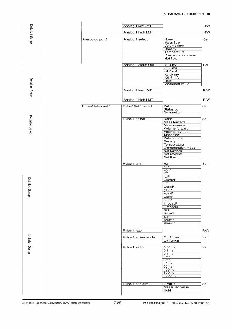
7. PARAMETER DESCRIPTION
7-25 IM 01R04B04-00E-E 7th edition March 06, 2009 -00All Rights Reserved. Copyright © 2003, Rota Yokogawa
Pulse/Status out 1 Pulse/Stat 1 select Pulse Sel Status out No function Pulse 1 select None Sel Mass forward Mass reverse Volume forward Volume reverse Volume flow Density Temperature Concentration meas Net forward Net reverse Net flow Pulse 1 unit Hz Sel g/P kg/P
t/P lb/P Cucm/P l/P Cum/P gal/P kgal/P Cuft/P bbl/P Impgal/P kImpgal/P
Detailed Setup
Detailed Setup
D
etailed Setup
Mass flow
Pulse 1 rate R/W
Pulse 1 active mode On Active Sel
Off Active
Pulse 1 width 0.05ms Sel 0.1ms 0.5ms 1ms 5ms 10ms 50ms 100ms
Pulse 1 at alarm 0P/0Hz Sel
Measured value
500ms 1000ms
Analog 1 low LMT R/W Analog 1 high LMT R/W
Analog output 2 Analog 2 select None Sel
Mass flow
Volume flow
Density
Temperature
Concentration meas
Net flow
Detailed Setup
Analog 2 alarm Out <2.4 mA Sel
<3.6 mA
<4.0 mA
>21.0 mA
>21.6 mA
Hold
Measured value
Analog 2 low LMT R/W Analog 2 high LMT R/W
Detailed Setup
Hold
Sl/P
Nl/P
Scum/P
Ncum/P
Scuft/P

7. PARAMETER DESCRIPTION
7-26IM 01R04B04-00E-E 7th edition March 06, 2009 -00 All Rights Reserved. Copyright © 2003, Rota Yokogawa
Pulse/Status out 2 Pulse/Stat 2 select Pulse Sel Status out No function
Pulse 2 select None Sel Mass forward Mass reverse Volume forward Volume reverse Mass flow Volume flow Density Temperature Concentration meas Net forward Net reverse Net flow Pulse 2 unit Hz Sel g/P Kg/P t/P lb/P Cucm/P l/P Cum/P gal/P kgal/P Cuft/P bbl/P Impgal/P kImpgal/P
D
etailed Setup Detailed Setup
Detailed Setup
Pulse 2 rate R/W Pulse 2 active mode On Active Sel Off Active Pulse 2 width 0.05ms Sel 0.1ms 0.5ms 1ms 5ms 10ms 50ms 100ms
Pulse 2 at alarm
500ms 1000ms
SO1 active mode On Active Sel Off Active
SO1 function No function Sel
Flow direction
Total switch
Mass flow alm 1
Mass flow alm 2
Mass flow alm 1+2
Vol flow alm 1
Vol flow alm 2
Vol flow alm 1+2
Density alm 1
Density alm 2
Density alm 1+2
Temp alm 1
Temp alm 2
Temp alm 1+2
Concentr. meas alm 1
Concentr. meas alm 2
Concentr. meas alm1+2
Net flow alm 1
Net flow alm 2
Net flow alm 1+2
Slug alarm
Empty alarm
Corrosion alarm
Detailed Setup
All alarms
0P/0Hz Sel Measured value Hold
Sl/P
Nl/P
Scum/P
Ncum/P
Scuft/P

7. PARAMETER DESCRIPTION
7-27 IM 01R04B04-00E-E 7th edition March 06, 2009 -00All Rights Reserved. Copyright © 2003, Rota Yokogawa
Status input SI function No function Sel Autozero
Total reset 0% signal lock SI active mode On Active Sel Off Active Totalizer Sel
Total unit mass g
Sel
kg
t
lb
Detailed Setup
Cucm
Total unit volume
SO2 active mode On Active Sel Off Active
Detailed Setup
SO2 function No function Sel
Flow direction
Total switch
Mass flow alm 1
Mass flow alm 2
Mass flow alm 1+2
Vol flow alm 1
Detailed Setup
Vol flow alm 2
Vol flow alm 1+2
Density alm 1
Density alm 2
Density alm 1+2
Temp alm 1
Temp alm 2
Temp alm 1+2
Concentr. meas alm 1
Concentr. meas alm 2
Concentr. meas alm1+2
Net flow alm 1
Net flow alm 2
Net flow alm 1+2
Slug alarm
Empty alarm
Corrosion alarm
All alarms
Total switch select Mass Volume Net
Total switch R/W
Total at alarm Hold Sel
Continue total
Total reset cntrl Inhibit Sel
Enable
Total reset Exe
Sel
Total unit net g
Sel
kg
t
lb
Sel
MJ
Total unit energy Btu
R/W
Heat of combustion
Energy factor Heat of combust unit MJ/kg Sel
Btu/lb MJ/Ncum Btu/Scuft
l Cum gal kgal
Impgal
kImpgal
Cuft
bbl
Nl Ncum Sl Scuft Scum
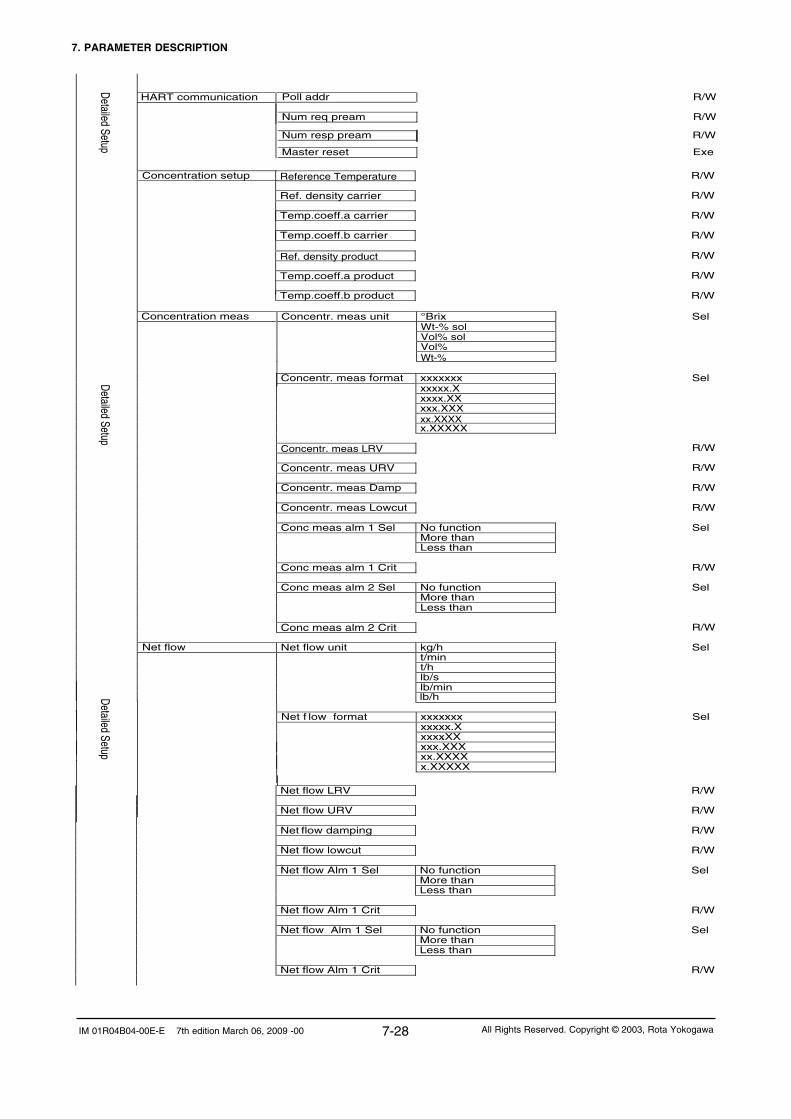
7. PARAMETER DESCRIPTION
7-28IM 01R04B04-00E-E 7th edition March 06, 2009 -00 All Rights Reserved. Copyright © 2003, Rota Yokogawa
Net flow LRV R/W
Net flow URV R/W Net flow damping R/W Net flow lowcut R/W Net flow Alm 1 Sel No function Sel More than Less than Net flow Alm 1 Crit R/W Net flow Alm 1 Sel No function Sel More than Less than Net flow Alm 1 Crit R/W
Detailed Setup
Net f low format xxxxxxx Sel xxxxx.X xxxx.XX xxx.XXX xx.XXXX x.XXXXX
Concentration meas
Concentr. meas format xxxxxxx Sel xxxxx.X xxxx.XX xxx.XXX xx.XXXX x.XXXXX
Concentr. meas LRV R/W Concentr. meas URV R/W Concentr. meas Damp R/W Concentr. meas Lowcut R/W Conc meas alm 1 Sel No function Sel More than Less than Conc meas alm 1 Crit R/W Conc meas alm 2 Sel No function Sel More than Less than Conc meas alm 2 Crit R/W
Net flow Net flow unit kg/h Sel t/min t/h lb/s lb/min
lb/h
HART communication
Poll addr R/W
Num req pream R/W
Master reset Exe
Num resp pream R/W
Concentr. meas unit °Brix Wt-% sol Vol% sol Vol% Wt-%
Sel
Concentration setup Reference Temperature R/W Ref. density carrier R/W Temp.coeff.a carrier R/W Temp.coeff.b carrier R/W Ref. density product R/W Temp.coeff.a product R/W Temp.coeff.b product R/W
Detailed Setup Detailed Setup

7. PARAMETER DESCRIPTION
7-29 IM 01R04B04-00E-E 7th edition March 06, 2009 -00All Rights Reserved. Copyright © 2003, Rota Yokogawa
Corrosion detect Corrosion alm sel Not apply Sel Apply Corrosion crit R/W Corrosion damp R/W Fluid max temp R Device information Tag R/W Long Tag R/W Descriptor R/W Message R/W Date R/W Sensor model R Sensor S/N R
Assembly number R
Device id
R
Universal rev
R
Fld dev rev
R
Software rev
R
Hardware rev
Review device info
Distributor
R
Sensor model
R
Sensor S/N
R
Assembly number
R
Tag
Review device info
R
Long Tag
R
Descriptor
R
Message
R
Date
R
R
R
Device S/W version
Device S/W date
Device S/W
Device S/W version
Device S/W date
R
R
Measuring Range R
Slug detection Slug alarm select Not apply Sel
Apply
Drive gain R Slug criteria R/W Slug duration R/W
After slug Measured value Sel Hold
Empty pipe detect Empty pipe alm sel Not apply Sel
Apply Empty pipe crit R/W After empty pipe Massflow = Zero Sel Measured Value Hold
Drive gain damping
Detailed Setup Detailed Setup
R
Serial no. converter R Serial no. detector R
Serial no. Converter Serial no. Detector
R R

7. PARAMETER DESCRIPTION
7-30IM 01R04B04-00E-E 7th edition March 06, 2009 -00 All Rights Reserved. Copyright © 2003, Rota Yokogawa
Pressure unit R
Pressure
R
Density alm 2 sel Density alm 2 crit
Density unit R Density LRV R Density URV R Density damping R Density lowcut R Density alm 1 sel R
Density alm 1 crit R
Flow direction R Mass flow unit R Mass flow LRV R Mass flow LRV R Mass flow damping R Mass flow lowcut R Mass flow alm 1 sel R Mass flow alm 1 crit R
Review FldDev vars 1
Mass flow alm 2 sel R Mass flow alm 2 crit R MF fixed value R Vol flow unit R Vol flow LRV R Vol flow URV R Vol flow damping R Vol flow lowcut R Vol flow alm 1 sel R Vol flow alm 1 crit R Vol flow alm 2 sel R Vol flow alm 2 crit R
R
R
R
SK20
R
SKT
R RV
R Qnom
R SKP
R
fl20 R FTC1 R FTCK R FPC R
Autozero value
R
Review sensor
KD
FQC1 FQC2 R
R
R
SKTK
Review FldDev vars 1
Density offset R
Reference density
R
FPTC R
R SKPT

7. PARAMETER DESCRIPTION
7-31 IM 01R04B04-00E-E 7th edition March 06, 2009 -00All Rights Reserved. Copyright © 2003, Rota Yokogawa
Analog 1 select R Analog 1 alarm out R Analog 1 low LMT R Analog 1 high LMT R
R
Analog 2 select
R
Analog 2 alarm out
R
Analog 2 low LMT
R Analog 2 high LMT
Review
Outputs/ Input
Concentration meas Unit R Concentration meas LRV R Concentration meas URV R Concentration meas Damp R Concentration meas Lowcut R Conc meas alm 1Sel R Conc meas alm 1Crit R Conc meas alm 2 Sel R Conc meas alm 2 Crit R Net flow Unit R Net flow LRV R Net flo w URV R Net flow damping R Net flow lowcut R Net flow Alm1 sel R Net flow Alm 1 crit R Net flow Alm 2sel R Net flow Alm 2 crit R
Review
FldDev var
s 2 R
evie FldDev vars 2
Temperature unit R Temperature LRV R Temperature URV R Temperature damping R Temp range select R Temp alarm 1 select R Temp alarm 1 crit R Temp alarm 2 select R Temp alarm 2 crit R Temp fixed value R
Review
FldDev vars 1
Velocity unit R

7. PARAMETER DESCRIPTION
7-32IM 01R04B04-00E-E 7th edition March 06, 2009 -00 All Rights Reserved. Copyright © 2003, Rota Yokogawa
Pulse/Status 1 select R
Pulse 1 active mode R Pulse 1 select R Pulse 1 unit R Pulse 1 rate R Pulse 1 width R Pulse 1 at alarm R SO 1 function R Pulse/Status 2 select R Pulse 2 active mode R Pulse 2 select R Pulse 2 unit R Pulse 2 rate R Pulse 2 width R Pulse 2 at alarm R SO 2 function R SI function R SI active mode R Total switch select R Total unit mass R
Total switch
R
Total at alarm
R
Total reset cntrl
R
R
eview O
utputs/ Input Review
Outputs/ Input
Poll addr
R
Num req pream
R
Review
HA
RT
Num resp pream
Total unit volume Total unit net
R
R
R
Total unit energy Heat of combust unit
Heat of combustion
R R R

7. PARAMETER DESCRIPTION
7-33 IM 01R04B04-00E-E 7th edition March 06, 2009 -00All Rights Reserved. Copyright © 2003, Rota Yokogawa
7.4 Parameter tree, HART menu
Online Device setup Set parameters for Rotamass (see below)
PV Display process value in engineering unit.
PV AO Display analogue output in mA.
Review Review parameters for Rotamass (see below)
Service Not open
View fld dev vars Mass flo R
DeviceSetup
Volume flo R
Dens R
Temp R
English
German
Language
French
View Outputs Analog output 1 PV R PV AO R % rnge R Analog output 2 SV R SV AO R % rnge R Pulse/Status out 1 TV Freq R SO 1 function R Pulse/Status out 2 TV Freq R SO 2 function R View Input Input function R Totalizer Total res cntrl Inhibit Sel Enable Total reset Exe
Process variables P
rocess variables
Self test/Status Self test LCD/Key Test Exe Self Test Exe Status Event overview R Error R Alarm R Warning R Hist Overview ord Hist Overview ord R Clear History Not execute Exe Execute Hist Overview abs History Set Abs R Set1 R : Set 10 R History set menu History Set R Hist Overview R H. error R H. Alarm R H. Warning R Clear History Exe
Diag / S
ervice
R-Total mass R D-Total mass R
Conc. meas
R
Net flo
R F-Total vol R-Total vol D-Total vol F-Total net R-Total net D-Total net F-Total energy Velocity
R R R R R R R R
F-Total mass R

7. PARAMETER DESCRIPTION
7-34IM 01R04B04-00E-E 7th edition March 06, 2009 -00 All Rights Reserved. Copyright © 2003, Rota Yokogawa
Input/Output test Analog Out 1 R/W Analog Out 2 R/W Pulse Out 1 R/W Status Out 1 R/W Pulse Out 2 R/W Status Out 2 R/W Status Input R Auto zero check Autozero history R AZ range R
AZ fluctuation R
Autozero Zero tuning Inhibit Sel Enable Autozero Autozero duration 3 min Sel 30 s Perform auto zero Exe Autozero value R Loop trim Trim output 1 Exe Trim output 2 Exe
Diag / Service
Tag R/W Long Tag R/W Display config Mass flo Volume flo Dens Temp
Basic Setup Basic Setup Basic Setup
Disp select 1 Sel F -Total mass R-Total mass D -Total mass
F-Total volume R-Total volume D -Total volume
F-Total energy Velocity
Concentration meas Net flow
F-Total net R-Total net D -Total net
Mass floVolume floDensTemp
Disp select 2 Sel
F-Total mass R-Total mass D -Total mass F-Total volume R-Total volume D -Total volume
F-Total energy Velocity
Concentration meas Net flow
F-Total net R-Total net D -Total net
Mass floVolume floDensTemp
Disp select 3 Sel
F-Total mass R-Total mass D -Total mass F-Total volume R-Total volume D -Total volume
F-Total energy Velocity
Concentration meas Net flow
F-Total net R-Total net D -Total net

7. PARAMETER DESCRIPTION
7-35 IM 01R04B04-00E-E 7th edition March 06, 2009 -00All Rights Reserved. Copyright © 2003, Rota Yokogawa
Mass flo Mass flo unit g/s Sel g/min g/h kg/s kg/min kg/h MetTon/min MetTon/h lb/s
Basic Setup
lb/min lb/h Mass flo LRV R/W Mass flo URV R/W Mass flow Damping R/W Dens Dens unit g/ml Sel
kg/l kg/Cum lb/gal lb/Cuft
Basic Setup Basic Setup
None
Mass floVolume floDensTemp
Disp select 4
Sel
F-Total mass R-Total mass D -Total mass F-Total volume R-Total volume D -Total volume
F-Total energy Velocity
Concentration meas Net flow
F-Total net R-Total net D -Total net
g/cc
Dens LRV R/W
Dens URV R/W
Dens Damping R/W
Temp Temp unit degC Sel degF Temp LRV R/W Temp URV R/W Temp Damping R/W Analog 1 select None Sel Mass flo Volume flo Dens Temp Conc meas Net flo Analog 2 select None Sel Mass flo Volume flo Dens Temp Conc meas Net flo Pulse/Status out 1 Pulse/Stat 1 select Pulse Sel Status out
No function
K
Display contrast R/W
°Bé hv °Bé lt °API

7. PARAMETER DESCRIPTION
7-36IM 01R04B04-00E-E 7th edition March 06, 2009 -00 All Rights Reserved. Copyright © 2003, Rota Yokogawa
TV unit Hz Sel g/P kg/P t/P lb/P
Cucm/P
l/P Cum/P gal/P kgal/P Cuft/P bbl/P
Impgal/P
kImpgal/P
Basic S
etup
B
asic Setup
Basic S
etup
Pulse out 1 Pulse 1 select None Sel Mass totl forw Mass totl rev Vol totl forw Vol totl rev Net totl forw Net totl rev Mass flo Vol flo Dens Temp Conc meas Net flow
TV rate R/W Status out 1 SO 1 function No Function Sel Bi-directional Total Switch
Mass flo alm 1 Mass flo alm 2 Mass flo alm 1+2 Vol flo alm 1 Vol flo alm 2 Vol flo alm 1+2 Dens alm 1 Dens alm 2 Dens alm 1+2 Temp alm 1 Temp alm 2 Temp alm 1+2 Conc alm 1 Conc alm 2 Conc alm 1+2 Net flo alm 1 Net flo alm 2 Net flo alm 1+2 Slug alarm Empty alarm, Corrosion alarm
Pulse/Status out 2 Pulse/Stat 2 select Pulse Sel
Status out No function Pulse out 2 Pulse 2 select None Sel
Mass totl forw Mass totl rev Vol totl forw Vol totl rev Net totl forw Net totl rev Mass flo Vol flo Dens Temp Conc meas Net flow
All alarms
Sl/P
Nl/P
Scum/P
Ncum/P
Scuft/P

7. PARAMETER DESCRIPTION
7-37 IM 01R04B04-00E-E 7th edition March 06, 2009 -00All Rights Reserved. Copyright © 2003, Rota Yokogawa
Status out 2 SO 2 function No Function Sel Bi-directional Total Switch Mass flo alm 1 Mass flo alm 2 Mass flo alm 1+2 Vol flo alm 1 Vol flo alm 2 Vol flo alm 1+2 Dens alm 1
Dens alm 2 Dens alm 1+2 Temp alm 1
Temp alm 2 Temp alm 1+2 Conc alm 1 Conc alm 2 Conc alm 1+2 Net flo alm 1 Net flo alm 2
Net flo alm 1+2 Slug alarm Empty alarm Corrosion alarm Input function No function Sel Autozero Total reset 0% signal lock
Basic Setup
Basic SetupBasic Setup
All alarms
Totalizer
Sel
Sel
Total switch sel Mass
Volume Net mass
F-Total mass Unit g kg
Met Ton lb
Cucm l Cum gal kgal
F-Total vol Unit
F-Total net Unit g
kg Met Ton lb
Sel
TV unit Hz Sel
g/P kg/P t/P lb/P Cucm/P l/P Cum/P gal/P kgal/P Cuft/P bbl/P Impgal/P kImpgal/P
TV rate R/W
Impgal
kImpgal
Cuft
bbl
NlNcumSlScuftScum
Sl/P
Nl/P
Scum/P
Ncum/P
Scuft/P

7. PARAMETER DESCRIPTION
7-38IM 01R04B04-00E-E 7th edition March 06, 2009 -00 All Rights Reserved. Copyright © 2003, Rota Yokogawa
Display contrast R/W Display period 0.5 s Sel
1.0 s
2.0 s
Detailed Setup
Mass floVolume floDensTemp
Disp select 3 Sel
F -Total mass R-Total mass D -Total mass F-Total volume R-Total volume D -Total volume
F-Total energy Velocity
Concentration meas Net flow
F-Total net R-Total net D -Total net
None
Mass floVolume floDensTemp
Disp select 4 Sel
F-Total mass R-Total mass D -Total mass F-Total volume R-Total volume D -Total volume
F-Total energy Velocity
Concentration meas Net flow
F-Total net R-Total net D -Total net
Detailed Setup
English
German
Language
French
Sel
Detailed Setup
D
etailed Setup
Display config Mass floVolume floDensTemp
Disp select 1 Sel
F -Total mass R-Total mass D -Total mass
F-Total volume R-Total volume D -Total volume
F-Total energy Velocity
Concentration meas Net flow
F-Total net R-Total net D -Total net
Mass floVolume floDensTemp
Disp select 2 Sel
F-Total mass R-Total mass D -Total mass F-Total volume R-Total volume D -Total volume
F-Total energy Velocity
Concentration meas Net flow
F-Total net R-Total net D -Total net

7. PARAMETER DESCRIPTION
7-39 IM 01R04B04-00E-E 7th edition March 06, 2009 -00All Rights Reserved. Copyright © 2003, Rota Yokogawa
Mass flow alm 2 sel No function Sel More than Less than Mass flow alm 2 crit R/W Mass flo fix sel Inhibit Sel Enable Mass flo fix menu Mass flow fixed val R/W
Mass flo Mass flo Unit g/s Sel
g/min g/h kg/s kg/min kg/h t/min t/h lb/s lb/min lb/h Mass flo Format xxxxxxx Sel xxxxx.X xxxx.XX xxx.XXX xx.XXXX x.XXXXX Mass flo LRV R/W Mass flo URV R/W Mass flo damping R/W Mass flo Lowcut R/W Mass flo alm 1 sel No function Sel More than Less than Mass flow alm 1 crit R/W
Detailed Setup
Detailed Setup
Sensor model RCCS30 Sel
RCCS31 RCCS32 RCCS33 RCCS34 RCCS36 RCCS38 RCCS39 RCCS39/IR
Sensor constants Mass flo SK20 R/W
SKT R/W
Detailed Setup
Detailed Setup
RCCS39/XR
RV R/W Qnom R/W SKP R/W
Dens KD R/W Fl20 R/W FTC1 R/W FTCK R/W
Config fld vars Flow direction Forward Sel Reverse
FQC1 R/W FQC2 R/W
FPC R/W
SKTK R/W
SKPT R/W
FPTC R/W

7. PARAMETER DESCRIPTION
7-40IM 01R04B04-00E-E 7th edition March 06, 2009 -00 All Rights Reserved. Copyright © 2003, Rota Yokogawa
Detailed S
etup Vol flo alm 1 sel No function Sel More than Less than Vol flo alm 1 crit R/W Vol flo alm 2 sel No function Sel More than Less than Vol flo alm 2 crit R/W
Dens Dens Unit g/ml Sel kg/l kg/Cum lb/gal lb/Cuft
g/cc
Detailed S
etup
Dens Format xxxxxxx Sel xxxxx.X xxxx.XX xxx.XXX xx.XXXX x.XXXXX
Vol flo Vol flo Unit Cucm/s Sel
Vol flo Format xxxxxxx Sel
xxxxx.X xxxx.XX xxx.XXX xx.XXXX x.XXXXX
Vol flo LRV R/W Vol flo URV R/W Vol flo Damping R/W Vol flo Lowcut R/W
Cucm/min Cucm/h l/s I/min l/h Cum/s Cum/min Cum/h gal/s gal/min gal/h Cuft/s Cuft/min Cuft/h bbl/s bbl/min bbl/h
Impgal/s
Impgal/min
Impgal/h
bbl/d
Nl/s Nl/min Nl/h Ncum/s Ncum/minNcum/h Sl/s Sl/min
Scuft/s
Scuft/min
Scuft/h
Sl/h
Scum/s Scum/min Scum/h
Detailed S
etup
°Bé hv °Bé lt °API

7. PARAMETER DESCRIPTION
7-41 IM 01R04B04-00E-E 7th edition March 06, 2009 -00All Rights Reserved. Copyright © 2003, Rota Yokogawa
Detailed Setup
Detailed Setup
Dens alm 1 sel No function Sel More than Less than Dens alm 1 crit R/W Dens alm 2 sel No function Sel More than Less than Dens alm 2 crit R/W Dens fix val sel Inhibit Sel Enable Dens fix menu Referenc density R/W
Pressure R
Temp Temp Unit degC Sel degF Kelvin Temp Format xxxxxxx Sel xxxxx.X xxxx.XX xxx.XXX xx.XXXX x.XXXXX Temp LRV R/W Temp URV R/W Temp Damping R/W Temp alm 1 sel No function Sel More than Less than Temp alm 1 crit R/W Temp alm 2 sel No function Sel More than Less than Temp alm 2 crit R/W Temp fix val sel Inhibit Sel Enable Temp fix menu Temp fixed value R/W Temp gain adjust
Dens LRV R/W Dens URV R/W Dens Damping R/W Dens Lowcut R/W
Pressur Unit bar Sel
psi
Velocity unit m/s
ft/s
Sel
Detailed SetupDetailed Setup
Config Output/Input Analog output 1 Analog 1select None Sel
Mass flow Volume flow Density Temperature Concentration meas Net flow Analog 1 alarm Out <2.4 mA Sel <3.6 mA <4.0 mA >21.0 mA >21.6 mA Hold Measured value
Analog 1 low LMT R/W Analog 1 high LMT R/W

7. PARAMETER DESCRIPTION
7-42IM 01R04B04-00E-E 7th edition March 06, 2009 -00 All Rights Reserved. Copyright © 2003, Rota Yokogawa
Analog Output 2 Analog 2 select None Sel Mass flow Volume flow Density Temperature Concentration meas Net flow SV Alarm 2 select <2.4mA Sel <3.6mA <4.0mA >21.0mA >21.6mA
Hold
Measured value
Analog 2 low LMT R/W
Analog 2 high LMT R/W
Pulse/Status 1 Pulse/Stat 1 sel Pulse Sel Status out No function Pulse/freq out 1 Pulse 1 select None Sel Mass totl forw Mass totl rev Vol totl forw Vol totl rev Net totl forw Net totl rev Mass flo Vol flo Dens Temp Conc meas Net flow Freq /Pulse out 1 TV Pls Unit Sel
D
etailed Setup
Detailed S
etup D
etailed Setup
TV Pls Rate R/W
Pls Mode Sel
On Active
Off Active
TV Pls Width Sel
0.05ms
0.1ms
0.5ms
1ms
5ms
10ms
50ms
100ms
500ms
1000ms
TV Pls Alarm Sel
0P/0Hz Measured value
Hz g/P
kg/P t/P
lb/P Cucm/P
l/P Cum/P
gal/P kgal/P Cuft/P bbl/P
Impgal/P kImpgal/P
Hold
Sl/P
Nl/P
Scum/P
Ncum/P
Scuft/P

7. PARAMETER DESCRIPTION
7-43 IM 01R04B04-00E-E 7th edition March 06, 2009 -00All Rights Reserved. Copyright © 2003, Rota Yokogawa
Status out 1 SO1 function No Function Sel Bi-directional Total Switch Mass flo alm 1
Mass flo alm 2 Mass flo alm 1+2 Vol flo alm 1 Vol flo alm 2 Vol flo alm 1+2 Dens alm 1 Dens alm 2 Dens alm 1+2 Temp alm 1 Temp alm 2 Temp alm 1+2 Conc alm 1 Conc alm 2
Detailed Setup
Conc alm 1+2
Net flo alm 1
Net flo alm 2
Net flo alm 1+2
Slug alarm
Empty alarm
Corrosion alarm
SO1 active mode On Active Sel Off Active
Pulse/Status 2 Pulse/Stat 2 sel Pulse Sel
Status out No function Pulse/freq out 2 Pulse 2 select None Sel
Mass totl forw Mass totl rev Vol totl forw Vol totl rev Net totl forw Net totl rev Mass flo Vol flo Dens Temp Conc meas Net flow Freq /Pulse out 2 TV Pls Unit Sel
Detailed Setup
Detailed Setup
TV Pls Rate R/W
Pls Mode Sel
On Active
Off Active
TV Pls Width Sel
0.05ms
0.1ms
0.5ms
1ms
5ms
10ms
50ms
100ms
Detailed Setup
500ms1000ms
All alarms
Hz g/P
kg/P t/P
lb/P Cucm/P
l/P Cum/P
gal/P kgal/P Cuft/P bbl/P
Impgal/P kImpgal/P
TV Pls Alarm Sel
0P/0Hz Measured value
Hold
Sl/P
Nl/P
Scum/P
Ncum/P
Scuft/P
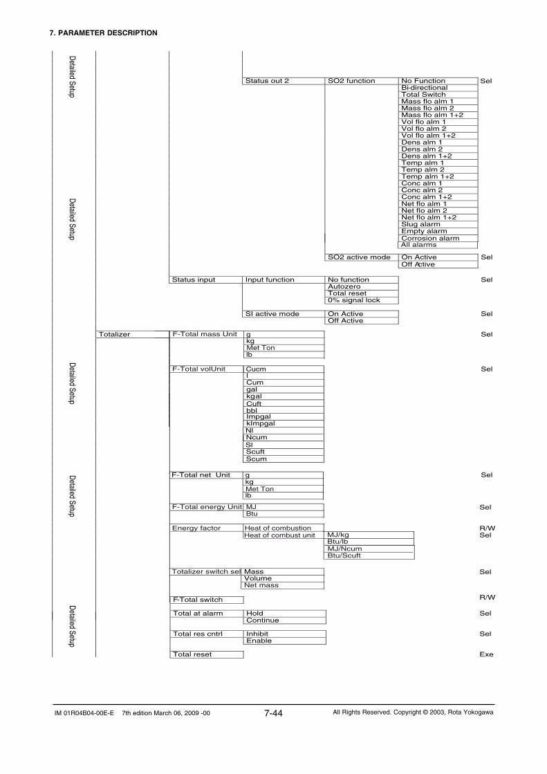
7. PARAMETER DESCRIPTION
7-44IM 01R04B04-00E-E 7th edition March 06, 2009 -00 All Rights Reserved. Copyright © 2003, Rota Yokogawa
Status out 2 SO2 function No Function Bi-directional Total Switch
Detailed Setup
Mass flo alm 1 Mass flo alm 2 Mass flo alm 1+2 Vol flo alm 1 Vol flo alm 2 Vol flo alm 1+2 Dens alm 1 Dens alm 2 Dens alm 1+2 Temp alm 1 Temp alm 2 Temp alm 1+2 Conc alm 1 Conc alm 2 Conc alm 1+2
Detailed Setup
Net flo alm 1 Net flo alm 2 Net flo alm 1+2 Slug alarm
Empty alarm Corrosion alarm
SO2 active mode On Active Sel
Off Active
Status input Input function No function Sel Autozero
Total reset 0% signal lock SI active mode On Active Sel Off Active Totalizer Sel
Sel
R/W
Sel
Sel
Exe
R/W
Detailed Setup Detailed Setup
Sel
All alarms
F-Total mass Unit g
kg
Met Ton
lb
Cucm
F-Total volUnit
Totalizer switch sel
F-Total switch Total at alarm Hold Continue Total res cntrl Inhibit Enable Total reset
Mass Volume Net mass
F-Total energy Unit MJ
Btu
Energy factor Heat of combustion
Heat of combust unit
Sel
MJ/kgBtu/lb MJ/NcumBtu/Scuft
F-Total net Unit g
Sel
kg
lb Met Ton
Sel
Sel
Detailed Setup
lCum gal kgal
Impgal
kImpgal
Cuft
bbl
NlNcumSlScuftScum

7. PARAMETER DESCRIPTION
7-45 IM 01R04B04-00E-E 7th edition March 06, 2009 -00All Rights Reserved. Copyright © 2003, Rota Yokogawa
Conc meas Format xxxxxxx Sel xxxxx.X xxxx.XX xxx.XXX xx.XXXX x.XXXXX Conc meas LRV R/W Conc meas URV R/W Conc meas Damp R/W Conc meas Lowcut Coc meas alm 1 sel No function Sel More than Less than Conc meas alm 1 crit R/W Coc meas alm 1 sel No function Sel More than Less than Conc meas alm 1 crit R/W
Net flo Net flo Unit kg/h Sel t/min t/h lb/s lb/min lb/h Net flo Format xxxxxxx xxxxx.X
Sel
xxxx.XX xxx.XXX xx.XXXX x.XXXXX Net flo LRV R/W
Detailed Setup
Net flo URV R/W Net flo Damp R/W Net flo Lowcut R/W Net flow alm 1 sel No function Sel More than Less than Net flow alm 1 crit R/W Net flow alm 1 sel No function Sel More than Less than Net flow alm 1 crit R/W
Detailed Setup Detailed Setup
R/W
HART communication Poll addr Num req pream Num r esp preams Master reset
R/W
R/W
Exe
Conc meas Conc meas unit °Brix
Wt-% solVol% sol Vol% Wt-%
Sel
Conc meas setup Ref. temperature R/W Ref. dens. carrier R/W Coeff. a carrier R/W Coeff. b carrier R/W Ref. dens. product R/W Coeff. a product R/W Coeff. b product R/W
Detailed Setup

7. PARAMETER DESCRIPTION
7-46IM 01R04B04-00E-E 7th edition March 06, 2009 -00 All Rights Reserved. Copyright © 2003, Rota Yokogawa
Empty pipe detect Empty pipe alm sel Not apply Sel Apply Empty pipe detect Empty pipe crit R/W After empty pipe Massflow = Zero Sel Measured Value Hold Corrosion detect Corrosion alm sel Not apply Sel Apply
Corrosion detect Corrosion crit R/W Corrosion damp R/W Fluid max temp R Device information Tag R/W
Long Tag R/W
Descriptor R/W Message R/W Date R/W Sensor model R Sensor S/N R Final asmbly num R Revision # ‘s Universal rev R Fld dev rev R Software rev R Hardware rev R
Detailed S
etup
Review Distributor R Sensor model R Sensor S/N R Final asmbly num R Tag R Long Tag R Descriptor R Message R
Review
device info
Date R Device id R Universal rev R Fld dev rev R Software rev R Hardware rev R
Review
device info
Detailed S
etup Device S/W
Device S/W version device S/W date
Device S/W version
Sel
R
RDevice S/W date
Measuring Range R Slug detection Slug alarm select Not apply Sel Apply
Slug detection Drive gain R Slug criteria R/W Slug duration R/W After slug Measured value Sel Hold
Drive gain damping

7. PARAMETER DESCRIPTION
7-47 IM 01R04B04-00E-E 7th edition March 06, 2009 -00All Rights Reserved. Copyright © 2003, Rota Yokogawa
Flow direction R Mass flo unit R Mass flo LRV R Mass flo LRV R Mass flo damp R Mass flo lowcut R Mass flo alm 1 select R Mass flo alm 1 crit R
Rev FldDev vars 1
Mass flo alm 2 select R Mass flo alm 2 crit R Mass flo fixed val R Vol flo unit R
Rev FldD
ev vars 1
Vol flo LRV R Vol flo URV R Vol flo damp R Vol flo lowcut R Vol flo alm 1 select R
Vol flo alm 1 crit R Vol flo alm 2 select R Vol flo alm 2 crit R Dens unit R Dens LRV R Dens URV R Dens damp R Dens lowcut R Dens alm 1 select R
Rev FldD
ev vars 1
Dens alm 1 crit R Dens alm 2 select R Dens alm 2 crit R Dens fixed value R
Pressure R
Pressure Unit R
Reference density R
R
SK20
R
SKT
R RV
R Qnom
R SKP
R
fl20 R FTC1 R FTCK R FPC R
Autozero value
R
R
eview sensor
KD
FQC1 FQC2 R
R
R
SKTK
FPTC R
R SKPT

7. PARAMETER DESCRIPTION
7-48IM 01R04B04-00E-E 7th edition March 06, 2009 -00 All Rights Reserved. Copyright © 2003, Rota Yokogawa
Temperature unit R Temp LRV R Temp URV R Temp damp R Temp range select R Temp alm 1 select R Temp alm 1 crit R Temp alm 2 select R Temp alm 2 crit R Temp fixed value R
Flow direction R Conc meas unit R Conc meas LRV R Conc meas URV R Conc meas damp R Conc meas lowcut R Conc alm 1select R Conc alm 1crit R Conc alm 2 sel R Conc alm 2 crit R Net flo unit R Net flo LRV R
Rev FldD
ev vars 2 Rev FldD
ev vars 2
Net flo URV R Net flo damping R Net flo lowcut R Net flo alm1 select R Net flo alm 1 crit R Net flo alm 2 select R Net flo alm 2 crit R
Rev FldD
ev vars 1
Velocity unit R

7. PARAMETER DESCRIPTION
7-49 IM 01R04B04-00E-E 7th edition March 06, 2009 -00All Rights Reserved. Copyright © 2003, Rota Yokogawa
Analog 1 select R PV Alarm 1 select R PV Analog 1 low LMT R PV Analog1 high LMT R
R
Analog 2 select
R
SV Alarm 2 select
R
SV Analog 2 low LMT
R
SV Analog2 high LMT
R R
Rev O
utputs/ Input Rev O
utputs/ Input
Pulse/Stat 1 sel
R
Pulse 1 select
R
Pls Unit
R
Pls Rate
R
Pls Mode
R
Pls Width
R
Pls Alarm
R
SO 1 function
R
SO 1 active mode
R
Pulse/Stat 2 sel
R
Pulse 2 select
R
Pls Unit
R
Pls Rate
R
Pls Mode
R
Pls Width
R
Pls Alarm
R
SO 2 function
R
SO 2 active mode
R
Input function
R
SI active mode
R
F-total mass Unit
R
F-total vol Unit
R
F-Total switch
Total at alarm
Total res cntrl
Poll addr R Num req preams R
Review
H
AR
T
Num resp preams R
F-total net Unit
R
Totalizer switch sel
R
F-total energy Unit
R
Heat of combustion Unit
R
Heat of combustion
R

7. PARAMETER DESCRIPTION
7-50IM 01R04B04-00E-E 7th edition March 06, 2009 -00 All Rights Reserved. Copyright © 2003, Rota Yokogawa
7.5 Mass flow functions (Basic or Detailed Setup)Mass flow To set the functions of mass flow measurement.
Mass flow unit Select : g/s, g/min, g/h, kg/s, kg/min,
kg/h, t/min,t/h, lb/s, lb/min, lb/h
Mass flow format Select : xxxxxxx, xxxxx.X, xxxx.XX,
xxx.XXX, xx.XXXX, x.XXXXX
Mass flow LRV (low range value) Set a mass flow value to the 4mA or 0 Hz.LRV can also be negative to measure reverse flow. In this case set the lowcut to Zero.
Mass flow URV (upper range value)
Set a mass flow value to the 20mAor xxxxx Hz.URV - LRV ≥ 5% of Qnom
Mass flow damping
Set the damping time in s. Damping timeeffects outputs and display. After 5 timesdamping time the given value is displayed(t=63%).
Mass flow lowcut
Set the low cut. Low cut effects outputand display. A hysteresis of 0.05% of Qnomis given by the system.
Mass flow alm 1 sel
Select : no function, more than, less than
Mass flow alm 1 crit Select a mass flow alarm level. What happens in case of an alarm has to be defined in Status out (7.11, 7.12).
Mass flow alm 2 sel
Mass flow alm 2 crit
Restrictions:
All alarms have to be in 0 - 110% of URV-LRV
Alarm criteria 2 must always be larger thanalarm criteria 1.
Select a mass flow alarm level. What happensin case of an alarm has to bedefined in Status out (7.11, 7.12).
Mass flow fix val sel Select: Inhibit, Enable
Mass flow fixed value Select a fix Mass flow value (only for test purpose or in case of maintenance).The set value is added to the actual value. In case of no flow it will vary with the zerofluctuation.
T72.EPS
Select : no function, more than, less than

7. PARAMETER DESCRIPTION
7-51 IM 01R04B04-00E-E 7th edition March 06, 2009 -00All Rights Reserved. Copyright © 2003, Rota Yokogawa
7.6 Volume flow functions (Basic or Detailed Setup)Volume flow To set the functions of volume flow measurement.
Notice: Volume flow is derived from density
and mass flow measurement.
Errors in density measurement (e.g. from gas
bubbles) effects the accuracy of volume flow. For
liquid it is recommended to use mass flow
as original measurement. Below roh = 0.3kg/l
Volume flow is set to zero (for liquids).
Vol flow unit
Select:
Cucm/s, Cucm/min, Cucm/h, l/s, l/min,l/h, Cum/s, Cum/min, Cum/h, gal/s,gal/min, gal/h, Cuft/s, Cuft/min, Cuft/h,bbl/s, bbl/min, bbl/h, Impgal/s, Impgal/min, Impgal/h, bbl/d, Nl/s, Nl/min, Nl/h, Ncum/s,Ncum/min, Ncum/h, Sl/s, Sl/min, Sl/h, Scuf/s,Scuft/min, Scuft/h, Scum/s, Scum/min, Scum/h
Nl/s, Nl/min, Nl/h, Ncum/s, Ncum/min, Ncum/honly for gas application.Sl/s, Sl/min, Sl/h, Scuf/s, Scuft/min, Scuft/h, Scum/s, Scum/min, Scum/h only for gas appli-cation or if Reference density value is selected.
Vol flow format
Select: xxxxxxx, xxxxx.X, xxxx.XX,
xxx.XXX, xx.XXXX, x.XXXXX
Vol flow LRV (low range value)
Set a volume flow value to the 4mA or 0 Hz.LRV can also be negative to measure reverse flow. In this case set the lowcut to Zero.
Vol flow URV (upper range value) Set a volume flow value to the 20mA or xxxxx Hz.URV - LRV ≥ 5% of Qnom
Vol flow damping Set the damping time in s. Damping time effects
outputs and display. After 5 times damping time
the given value is displayed (t=63%).
Vol flow lowcut Set the low cut. Low cut effects output and
display. A hysteresis of 0.05% of Qnom
(mass flow) is given by the system.
Vol flow alm 1 sel Select: no function, more than, less than
Vol flow alm 1 crit
Select a volume flow alarm level. What
happens in case of an alarm has to be
defined in Status out (7.12, 7.13).
Vol flow alm 2 sel
Select: no function, more than, less than
Vol flow alm 2 crit
Restrictions:
All alarms have to be in 0 - 110% of URV-LRV
Alarm criteria 2 must always be larger than alarm
criteria 1.
Select a volume flow alarm level. What happens
in case of an alarm has to be defined in Status out (7.12, 7.13).
T73.EPS

7. PARAMETER DESCRIPTION
7-52IM 01R04B04-00E-E 7th edition March 06, 2009 -00 All Rights Reserved. Copyright © 2003, Rota Yokogawa
7.7 Density functions (Basic or Detailed Setup)
can also be used to
Density To set the functions of density measurement.
Notice: Density measurement is only
reliable if there is no gas in the liquid.
For liquid measurement a density lower
0 .3kg/l is displayed as 0.0kg/l for gas
measurement set a fixed density value.
Density unit
Select
g/ml, kg/l, kg/Cum, lb/gal, lb/Cuft, g/cc, °Bé hv,°Bé lt, °API
°Bé hv, °Bé lt, °API only with option /CST
Density format Select : xxxxxxx, xxxxx.X, xxxx.XX,
xxx.XXX, xx.XXXX, x.XXXXX
Density LRV (low range value) Set a density value to the 4mA or 0 Hz.
Density URV (upper range value) Set a density value to the 20mA or xxxxx Hz.URV - LRV ≥ 0.05 kg/l
Density damping Set the damping time in s. Damping time
effects outputs and display. After 5 times
damping time the given value is
displayed (t = 63%).
Density lowcut Set the low cut. Low cut effects output and and display.
Density alm 1 sel Select: no function, more than, less than
Density alm 1 crit Select a density flow alarm level. What
happens in case of an alarm has to be
defined in Status out (7.12, 7.13).
Density alm 2 sel Select: no function, more than, less than
Density alm 2 crit
Restrictions:
All alarms have to be in 0 - 110% of URV-LRV
Alarm criteria 2 must always be larger than alarm
criteria 1.
Select a density flow alarm level. What
happens in case of an alarm has to be
defined in Status out (7.12, 7.13).
Density fix val sel Select: Inhibit, Enable
T74.EPS
Reference density Select a density value. For gas measurement (option /GA) set here your actual density for output of volume flow. For output of standard or normal volume flow set the standard or normal density of your gas accordingly. For liquid measurement this parameterenter the standard density of your liquid for output of standard volume flow or for the actual density in case of density disturbances.

7. PARAMETER DESCRIPTION
7-53 IM 01R04B04-00E-E 7th edition March 06, 2009 -00All Rights Reserved. Copyright © 2003, Rota Yokogawa
Pressure Set the static line pressure in bar or psi.Static pressure effect on density and mass flow will be automatically corrected.Only useful for RCCS36 and larger.
Pressure unit
Select : bar, psi
T74a.EPS
Density offset If the ROTAMASS detector is installed horizontally,the value from the following table must be enteredaccording to the concerning sensor model. RCCS30 13.50 g/l
RCCS31 1.80 g/lRCCS32 2.00 g/lRCCS33 0.60 g/lRCCx34 0.90 g/lRCCx36 0.35 g/lRCCx38 to 39/XR 0 g/l
(default)
ROTAMASS is density-calibrated vertically. If the ROTAMASS detector is installed horizontal an density offset value from the above table has to be entered to the parameter reference density. As positive values if the tubes are down and as negative value if the tubes are up..

7. PARAMETER DESCRIPTION
7-54IM 01R04B04-00E-E 7th edition March 06, 2009 -00 All Rights Reserved. Copyright © 2003, Rota Yokogawa
7.8 Temperature functions (Basic or Detailed Setup)
Temperature To set the functions of temperature measurement.
Notice: Standard range: -200 to 230°C
High temp. range: 0 to 400°C
Temperatureunit
Select
degC, degF, K
Temperature format
Select : xxxxxxx, xxxxx.X, xxxx.XX,
xxx.XXX, xx.XXXX, x.XXXXX
Temperature LRV (low range value)
Set a temperature value to the 4mA or 0 Hz
Temperature URV (upper range value)
Set a temperature value to the 20mA or xxxxx Hz.URV - LRV ≥ 10 K
Temperature damping
Set the damping time in s. Damping time
effects outputs and display. After 5 times
damping time the given value is displayed(t = 63%).
Temperature alm 1 sel Select: no function, more than, less than
Temperature alm 1 crit Select a temperature flow alarm level.
What happens in case of an alarm has to
be defined in Status out (7.12, 7.13).
Temperature alm 2 sel Select: no function, more than, less than
Temperature alm 2 crit
Restrictions:
All alarms have to be in 0 - 110% of URV-LRV
Alarm criteria 2 must always be larger than alarm
criteria 1.
Select a temperature flow alarm level.
What happens in case of an alarm has to
be defined in Status out (7.12, 7.13).
Temperature fix val select Select: Inhibit, Enable
Temperature fixed value
Select a temperature value in case of malfunction of the inbuilt temperature sensor.
Temperature gain
The ROTAMASS temperature sensor is
installed outside of the measuring tubes
So at high or low fluid temperature the
temperature measurement may show
larger errors as a function of the quality of
heat insulation. This function allows the correct
temperature measurement for better accuracy in
mass flow and density.
T75.EPS

7. PARAMETER DESCRIPTION
7-55 IM 01R04B04-00E-E 7th edition March 06, 2009 -00All Rights Reserved. Copyright © 2003, Rota Yokogawa
7.9 Velocity functions (Detailed Setup)
Velocity To set the function of the medium velocity.Not available for gas measurement (/GA)
Velocity unit Select : m/s, ft/s
T94.EPS
7.10 Analog 1 functions (Basic or Detailed Setup)Analog output 1 To set the current output 1. This output
provides HART communication.
Analog 1 select Select: None, Mass flow, Volume flow,
Density, Temperature , Concentration meas,
Net flow
If None is selected, output is 4mA,
HART communication is available.
Analog 1 alarm out
(Detailed setup, Configure
output/input)
If NAMUR is selected (default) :<3.6mA, >21mA, Hold, Measured value
If Not NAMUR is selected :<2.4mA, <3.6mA, <4mA, >21mA, >21.6mA
Analog 1 low LMT (low limit)
(Detailed setup, Configure output/input)
The alarm is active if the measured
value is lower than the low limit.
If NAMUR is selected (default) :
Measuring range from 3.8 - 20.5Alarm level: <3.6mA or >21.0mA
If Not NAMUR is selected :Measuring range from 2.7 - 21.3mAAlarm level: <2.4mA, >21.6mA
Analog 1 high LMT (high limit)
(Detailed setup, Configure output/input)
The alarm is active if the measured
value is higher than the high limit.
T76.EPS
If NAMUR is selected (default) :
Measuring range from 3.8 - 20.5Alarm level: <3.6mA or >21.0mA
If Not NAMUR is selected : Measuring range from 2.7 - 21.3mAAlarm level: <2.4mA, >21.6mA

7. PARAMETER DESCRIPTION
7-56IM 01R04B04-00E-E 7th edition March 06, 2009 -00 All Rights Reserved. Copyright © 2003, Rota Yokogawa
7.11 Analog 2 functions (Basic or Detailed Setup)
Analog output 2 To set the current output 2.
Analog 2 select Select: None, Mass flow, Volume flow,
Density, Temperature, Concentration meas,
Net flow
If None is selected, output is 4mA.
Analog 2 alarm out
(Detailed setup, Configure
output/input)
If NAMUR is selected (default) :<3.6mA, >21mA, Hold, Measured value
If Not NAMUR is selected :<2.4mA, <3.6mA, <4mA, >21mA, >21.6mA
Analog 2 low LMT (low limit)
(Detailed setup, Configure output/input)
The alarm is active if the measured
value is lower than the low limit.
If NAMUR is selected (default) :
Measuring range from 3.8 - 20.5Alarm level: <3.6mA or >21.0mA
If Not NAMUR is selected :Measuring range from 2.7 - 21.3mAAlarm level: <2.4mA, >21.6mA
Analog 2 high LMT (high limit)
(Detailed setup, Configure output/input)
The alarm is active if the measured
value is higher than the high limit.
T77.EPS
If NAMUR is selected (default) :
Measuring range from 3.8 - 20.5Alarm level: <3.6mA or >21.0mA
If Not NAMUR is selected : Measuring range from 2.7 - 21.3mAAlarm level: <2.4mA, >21.6mA
-10
0
10
20
30
40
50
60
70
80
90
100
110
-110 -90 -70 -50 -30 -10 10 30 50 70 90 110Reverse ← Flow [%] → Forward
Out
put c
urre
nt [%
]
2.4
4
5.6
7.2
8.8
10.4
12
13.6
15.2
16.8
18.4
20
21.6
Out
put c
urre
nt [m
A]
High-LMT 20.5 mA
Low-LMT 3.8 mA0
LRV ≥ 0 (e.g. 0)
LRV < 0 (e.g. -100% of flow)
possible Low cut
T76a.EPS
Example for Bi-directional flow:

7. PARAMETER DESCRIPTION
7-57 IM 01R04B04-00E-E 7th edition March 06, 2009 -00All Rights Reserved. Copyright © 2003, Rota Yokogawa
7.12 Pulse/Status output 1 functions (Basic or Detailed
Pulse/Status out 1 To set the pulse /status output 1.
Pulse/Stat 1 select Select: Pulse, Status out, No function
If Pulse is selected, Status out 1 (SO) is
not available.
If Status out is selected, Pulse
parameters are not available.
Pulse 1 select Select : None, Mass forward, Mass reverse,
Volume forward Volume reverse, Mass flow,
Volume flow, Density, Temperature,
Concentration meas, Net forward, Net reverse,
Net flow.
If Mass forward, Volume forward or Net forward
are selected, pulse output only works at forward
flow.
If Mass reverse, Volume reverse or Net
reverse are selected, pulse output only works at
reverse flow.
Pulse 1 unit Select : Hz, g/P, kg/P, t/P, lb/P, Cucm/P, l/P, Cum/P, gal/P, kgal/P, Cuft/P, bbl/P,
Impgal/P, kImpgal/P, Sl/P, Nl/P, Scum/P,
Ncum/P, Scuft/P
If Pulse 1 select is Mass flow, Volume flow, Density, Temperature or Concentration meas,
only Hz can be selected.
If Pulse 1 select is Mass forward, Mass reverse, Volume forward, Volume reverse, Net forwardor Net reverse, only unit/P can be selected.
Pulse 1 rate
The Pulse rate can be set according to the unitset in Pulse 1 unit.
Maximum pulse rate is 10000Hz.
Pulse 1 active mode
Select: On Active, Off Active
The output levels depending on this parameter are shown on page 7-61.
T78.EPS
To select the pulse output first mass or volumehas to be selected. If mass flow or volume flow is selected the output delivers only frequency.
NOTE
Nl/P, Ncum/P only for gas application.Sl/P, Scuf/P, Scum/P only for gas application or if Reference density value is selected.

7. PARAMETER DESCRIPTION
7-58IM 01R04B04-00E-E 7th edition March 06, 2009 -00 All Rights Reserved. Copyright © 2003, Rota Yokogawa
Pulse 1 width
Pulse 1 at alarm Select : 0P/0Hz, Measured value, Hold
If 0P/0Hz is selected, in case of alarm the pulse output is stopped.
If Measured value is selected, the pulse output
keeps on measuring.
SO 1 function Select : No Function, Flow direction, Total switch,
Mass flow alm 1, Mass flow alm 2,
Mass flow alm 1+2, Vol flow alm 1, Vol flow
alm 2, Vol flow alm 1+2, Density alm 1,
Density alm 2, Density alm 1+2, Temp alm 1,
Temp alm 2, Temp alm 1+2,
Concentartion meas alm 1, Concentartion meas
alm 2, Concentartion meas alm 1+2,
Net flow alm 1, Net flow alm 2, Net flow alm 1+2,
Slug alarm, Empty alarm, Corrosion alarm,
All alarms
If Bi - direction is selected, status output
becomes active for forward flow and not active
for reverse flow, if parameter flow direction is set to
forward. It is the other way round, if parameter
flow direction is set to reverse (see 7.14).
If Total switch is selected, status output becomes
active, when the totalizer reaches the value set to
parameter Total switch (see 7.14).
If an alarm function is selected, status output
becomes active, if the concerning alarm occurs.
If All alarms is selected, status output becomes
active, if at least one alarm occures.
SO1 active mode Select : On Active, Off Active
T79.EPS
Select : 0.05ms, 0.1ms, 0.5ms, 1ms, 5ms, 10ms,50ms, 100ms, 500ms, 1000ms
If Hold is selected, the pulse output keeps the
value before entering the alarm / error state.
The output levels depending on this parameter are shown on page 7-61.

7. PARAMETER DESCRIPTION
7-59 IM 01R04B04-00E-E 7th edition March 06, 2009 -00All Rights Reserved. Copyright © 2003, Rota Yokogawa
How to set status, pulse or frequency output(using the display keys, equivalent via HART)Status Basic Setup or Detailed Setup Pulse/Status out 1 Pulse/Stat 1 select Select : Status out
Pulse or FrequencyBasic Setup or Detailed Setup Pulse/Status out 1 Pulse/Stat 1 select Select : Pulse Pulse 1 select Mass Forward → Pulse Mass Reverse → Pulse Volume Forward → Pulse Volume Reverse → Pulse Mass Flow → Frequency Volume Flow → Frequency Density → Frequency Temperature → Frequency
Notice : By selecting a variable (mass or volume)which can be totalized automatically the pulseoutput is selected.
If ´Pulse´ is selected, under ´Basis Setup´ the Pulse unit and Pulse ratehave to be defined.Under ´Detailed Setup´ Pulse unit Pulse rate Pulse active mode and Pulse widthhave to be defined.
If the pulse output is set under ´Basic Setup´, the pulse width is the width set under ´Detailed Setup´If the pulse width is not configured under ´DetailedSetup´menu the pulse width will be set default to 1ms.
If ´frequency´ is selected the frequency generatedat URV (upper range value) has to be defined. Default is URV = 1000Hz.
Differences between Pulse and FrequencyoutputFor pulse output the mass (or volume) is internally totalized and if the increment is reached, one pulse is send.
For a frequency output the measured value is calculated in actual frequency according to the definition of the user (e.g. 10000Hz = 54321kg/h) with 50% duty cycle. Set as frequency output the pulse length is chang-ing with the change of the measured value.
Set as a pulse output the pulse length is constant but the time between the pulses varies. Even at constant flow the time between the pulses might vary because the microprocessor has to find a suitable gap in its timing to send the pulse.
Typical pattern for frequency output :
Typical pattern for pulse output(50ms; 0.1kg/p; 2580kg/h) :
2ms2ms
F1.EPS
100ms100ms
F2.EPS

7. PARAMETER DESCRIPTION
7-60IM 01R04B04-00E-E 7th edition March 06, 2009 -00 All Rights Reserved. Copyright © 2003, Rota Yokogawa
Setting the pulse outputBecause the duty cycle of pulses is max. 50%, the max. flowrate is restricted by the pulse width, the unit and the pulse rate :Max. flow rate =1s/(pulse width*2) *pulse rate *time factorExample :Max. Q should be calculated in kg/minPulse width = 50ms/PPulse rate = 0.1kg/PTime factor (related to s) = 60/minMax. Q = 1/ (0.05s/P *2) *0.1kg/P * 60/min = 60kg/minIf the flow is higher than max.Q pulses will be lost. Therefore it is mandatory to choose the pulse width/rate so, that the calculated max.Q is always 10% higher than the flowrate which can be generated.10% higher is recommended because the duty cycle is not always exact 50%. For certain pulse widths the duty cycle at max.Q is larger than 50% so fewer pulses can be generated. These pulses are delivered later when the flowrate is again below max.Q minus 10%. To avoid this situation it is recommended to keep the flowrate always 10% below max.Q.Example : Flowrate : 11t/h Pulse unit : kg Pulse rate : 0.1kg/PCheck : Lowest pulse width = 0,5* pulse rate* time factor/ max flow rate = 0.5*0.1kg *3600s/h /(11000kg/h) = 16.4ms → customer should select 10ms pulse width or lower. Max.Q = 18000kg/h 11000kg/h < 18000kh/h - 10%
Max. flowrate for different pulse settings reduced by 10%:Pulse Width in ms
1000 500 100 50 10 5 1 0.5 0.1 0.05Max. pulse sending frequency for the different pulse settings in P/s
0.45 0.9 4.5 9 45 90 450 900 4500 9000Pulse Unit
Pulse rate
Flow Unit
Maximum Flow Rate
g 0.1 g/h 162 324 1620 3240 16200 32400 162000 324000 1620000 3240000g 1 g/h 1620 3240 16200 32400 162000 324000 1620000 3240000g 10 g/h 16200 32400 162000 324000 1620000 3240000 --- --- ---kg 0.1 kg/h 162 324 1620 3240 16200 32400 162000 324000 1620000 3240000kg 1 kg/h 1620 3240 16200 32400 162000 324000 1620000 3240000 ---kg 10 kg/h 16200 32400 162000 324000 1620000 3240000 --- --- ---t 0.1 t/h 162 324 1620 3240 16200 --- --- --- --- ---t 1 t/h 1620 3240 16200 --- --- --- --- --- --- ---t 10 t/h 16200 --- --- --- --- --- --- --- --- ---
Result : Pulse width = 10ms Pulse rate = 0.1kg/P
For a first orientation the max.Q for certain pulse widths and units for a pulse rate of 0.1 , 1 and 10 are given in the table below.
Max. flow restriction :
t
flowMax flow from pulse width, unit, rate
this amount willbe lost
t
flowMax flow from pulse width, unit, rate
Grey zone
this amount willbe lost
F3.EPS

7. PARAMETER DESCRIPTION
7-61 IM 01R04B04-00E-E 7th edition March 06, 2009 -00All Rights Reserved. Copyright © 2003, Rota Yokogawa
The following tables show the physical output levels of the pulse / status outputs depending on the setting of parameter Pulse x active mode or SOx active mode.
On activeOutput Situation Output transistor Level Pout+ Level Pout+
Passive Active (/AP)
Pulse/Status out 1No Alarm/No Pulse open (OFF) High (Us)* High (15 VDC)
Alarm/Pulse closed (ON) Low (≤ 1 V) Low (≤ 1 V)
Level Sout+
Pulse/Status out 2No Alarm/No Pulse open (OFF) High (Us)*
Alarm/Pulse closed (ON) Low (≤ 1 V)
Off activeOutput Situation Output transistor Level Pout+ Level Pout+
Passive Active (/AP)
Pulse/Status out 1No Alarm/No Pulse closed (ON) Low (≤ 1 V) Low (≤ 1 V)
Alarm/Pulse open (OFF) High (Us)* High (15 VDC)
Level Sout+
Pulse/Status out 2No Alarm/No Pulse closed (ON) Low (≤ 1 V)
Alarm/Pulse open (OFF) High (Us)**) Us is the external power supply voltage of the pulse / status output
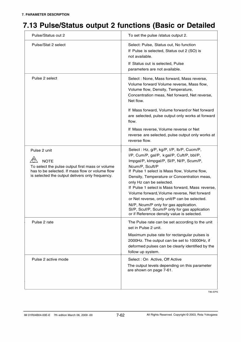
7. PARAMETER DESCRIPTION
7-62IM 01R04B04-00E-E 7th edition March 06, 2009 -00 All Rights Reserved. Copyright © 2003, Rota Yokogawa
7.13 Pulse/Status output 2 functions (Basic or Detailed Pulse/Status out 2 To set the pulse /status output 2.
Pulse/Stat 2 select Select: Pulse, Status out, No function
If Pulse is selected, Status out 2 (SO) is
not available. If Status out is selected, Pulse
parameters are not available.
Pulse 2 select
Select : None, Mass forward, Mass reverse,
Volume forward Volume reverse, Mass flow, Volume flow, Density, Temperature,
Concentration meas, Net forward, Net reverse,
Net flow.
If Mass forward, Volume forward or Net forward
are selected, pulse output only works at forward
flow.
If Mass reverse, Volume reverse or Net
reverse are selected, pulse output only works at
reverse flow.
Pulse 2 unit
Pulse 2 rate
The Pulse rate can be set according to the unit
set in Pulse 2 unit.
Maximum pulse rate for rectangular pulses is
2000Hz. The output can be set to 10000Hz, if
deformed pulses can be clearly identified by the
follow up system.
Pulse 2 active mode Select : On Active, Off Active
T80.EPS
To select the pulse output first mass or volumehas to be selected. If mass flow or volume flow is selected the output delivers only frequency.
NOTE
Select : Hz, g/P, kg/P, t/P, lb/P, Cucm/P,
l/P, Cum/P, gal/P, k gal/P, Cuft/P, bbl/P,
Impgal/P, kImpgal/P, Sl/P, Nl/P, Scum/P,
Ncum/P, Scuft/P
If Pulse 1 select is Mass flow, Volume flow,
Density, Temperature or Concentration meas,
only Hz can be selected. If Pulse 1 select is Mass forward, Mass reverse,
Volume forward, Volume reverse, Net forward
or Net reverse, only unit/P can be selected.
Nl/P, Ncum/P only for gas application.Sl/P, Scuf/P, Scum/P only for gas application or if Reference density value is selected.
The output levels depending on this parameter are shown on page 7-61.

7. PARAMETER DESCRIPTION
7-63 IM 01R04B04-00E-E 7th edition March 06, 2009 -00All Rights Reserved. Copyright © 2003, Rota Yokogawa
Pulse 2 width
Pulse 2 at alarm
Select : 0.05ms, 0.1ms, 0.5ms, 1ms, 5ms, 10ms,50ms, 100ms, 500ms, 1000ms
SO 2 function Select : No Function, Flow direction, Total switch,
Mass flow alm 1, Mass flow alm 2,
Mass flow alm 1+2, Vol flow alm 1, Vol flow
alm 2, Vol flow alm 1+2, Density alm 1,
Density alm 2, Density alm 1+2, Temp alm 1,
Temp alm 2, Temp alm 1+2,
Concentartion meas alm 1, Concentration meas
alm 2, Concentration meas alm 1+2,
Net flow alm 1, Net flow alm 2, Net flow alm 1+2,
Slug alarm, Empty alarm, Corrosion alarm,
All alarms
If Bi - direction is selected, status output
becomes active for forward flow and not active
for reverse flow if parameter flow direction is set to
forward. It is the other way round, if parameter
flow direction is set to reverse. (see 7.16).
If Total switch is selected, status output becomes
active, when the totalizer reaches the value set to
parameter Total switch (see 7.16).
SO2 active mode Select : On Active, Off Active
T81.EPS
If an alarm function is selected, status output
becomes active, if the concerning alarm occurs.
If All alarms is selected, status output becomes
active, if at least one alarm occures.
Select : 0P/0Hz, Measured value, Hold
If 0P/0Hz is selected, in case of alarm the pulse
output is stopped.
If Measured value is selected, the pulse output
keeps on measuring.
If Hold is selected, the pulse output keeps the
value before entering the alarm / error state.
The output levels depending on this parameter are shown on page 7-61.
Detailed information about using the pulse and status output see chapter 7.12.

7. PARAMETER DESCRIPTION
7-64IM 01R04B04-00E-E 7th edition March 06, 2009 -00 All Rights Reserved. Copyright © 2003, Rota Yokogawa
7.14 Status input functions (Basic or Detailed Setup)
Status input To set the status input.
SI function Select : No function, Autozero, Total reset, 0% signal lock
If Autozero is selected, active statusinput starts autozero.
If Total reset is selected, active statusinput sets totalizer to zero, if parameterTotal reset cntrl is enabled.
If 0% signal lock is selected, analog output 1and 2 are fixed to 4mA while status input isactive.
SI active mode Select : On Active, Off Active
If On Active is selected, the status input isclosed active.
If Off Active is selected, the status input isopen active.
T82.EPS

7. PARAMETER DESCRIPTION
7-65 IM 01R04B04-00E-E 7th edition March 06, 2009 -00All Rights Reserved. Copyright © 2003, Rota Yokogawa
7.15 Totalizer functions (Basic or Detailed Setup)
Totalizer To set totalizer function.
Totalizer increments the forward flow if flow direction is forward or the reverse flow if flow direction is reverse.
Total switch select Select : Mass, Volume, Net
Total unit
For Total unit mass or Total unit net g, kg, t, lb can be selected.
For Total unit volume Cucm, l, Cum, gal, kgal, Cuft, bbl, Impgal, kImpgal, Nl, Ncum, Sl, Scuft, Scum can be selected.
Total switch A totalizer limit can be set only to the forwardtotalizer selected in Total select. If status output is set to Total switch, status output is set active, if the totalizer reaches this value.Total switch is not active if set to 0.0.
Total at alarm
Select : Hold, Continue Total
Characteristic of totalizer selected in Total select in case of the Total switch is active. If hold is selected forward and reverse totalising stops.
Total reset cntrl
Select : Inhibit, Enable
Enables or inhibits total reset.
Total reset
Select : Execute, Not Execute
Execution of total reset. Forward and reverse total of the totalizer selected in Total select will be set to zero.
T83.EPS
Totalizer indication By setting via HART communication up to 3 totalizer (forward / reverse / differential) of the item selected in Total select can be displayed.By key-setting up to 4 totalizer can be displayed eligible from the 9 totalizer in Disp select 1 to 4.Note : If a totalizer item, which is not the item selected in Total select, is indicated by key selection with Disp select, the concerning Disp select parameter shows Unknown enumerator after selection by HART.
The totalizer can display 6 figures. In the range 1000000 to 9999999, total values are displayed with 7
figures. These are precise.
If the total value 9999999 is reached, the indication changes to exponential type.
During exponential indication the accuracy is lost. If full accuracy is needed, total reset must be
executed to reach precise indication.
For Total unit energy MJ and Btu can be selected.
Energy factor / Heat of combustion
Heat of combust. unit MJ/kg, Btu/lb, MJ/Ncum and Btu/Scuft can be selected.
Set the calorific value of the medium with theunit Energy factor / Heat of combust. unit.The totalized energy of the medium can be indicated on display by F-Total energy.
Nl, Ncum only for gas application.Sl, Scuf, Scum only for gas application or if Reference density value is selected.

7. PARAMETER DESCRIPTION
7-66IM 01R04B04-00E-E 7th edition March 06, 2009 -00 All Rights Reserved. Copyright © 2003, Rota Yokogawa
7.17 Concentration measurement (Detailed Setup)
Concentration meas(only for option /CST or /Cxx)
To set the functions of concentration
measurement.
Concentration meas format Select : xxxxxxx, xxxxx.X, xxxx.XX,
xxx.XXX, xx.XXXX, x.XXXXX
Concentration meas LRV (low range value)
Set a concentration value to the 4mA or 0 Hz.
Concentration meas (upper range value
Set a concentration value to the 20mA or xxxxx = Hz. URV - LRV ≥ 5% of 100%
Concentration meas damping Set the damping time in s. Damping time
effects outputs and display. After 5 times
damping time the given value is displayed
(t=63%).
Concentration meas lowcut Set the low cut. Low cut effects output
and display. A hysteresis of 0.05% of Qnom is
given by the system.
Concentration meas alm 1 sel Select : no function, more than, less than
Concentration meas alm 1 crit Select a concentration alarm level. What
happens in case of an alarm has to be
defined in Status out (7.12, 7.13).
Concentration meas alm 2 sel Select : no function, more than, less than
Concentration meas alm 2 crit
Restrictions:
All alarms have to be in 0 - 110% of URV-LRV
Alarm criteria 2 must always be larger than alarm criteria 1.
Select a concentration alarm level. What
happens in case of an alarm has to be
defined in Status out (7.12, 7.13).
T85.EPS
For xx = 00 to 99 a customer specific or defined table is stored in the converter in factoryFor /CST temperature coefficients have to be determined by the customer.
Concentration meas unit(only available for option /CST)
Select : °Brix, Wt-%.sol, Vol % sol, Wt-%, Vol %
7.16 Flow direction function (Detailed Setup)
Flow direction Select : Forward, Reverse
See 7.12. and 7.13 according influence onstatus output (SO 1/2 function = Bi-direction)
If Reverse is selected, the flow direction in the other direction of the arrow on the detector is used as “forward”.
T84.EPS

7. PARAMETER DESCRIPTION
7-67 IM 01R04B04-00E-E 7th edition March 06, 2009 -00All Rights Reserved. Copyright © 2003, Rota Yokogawa
Concentration meas setup(only for option /CST)
To setup the coefficients used for calculation of concentration using the Standard Concentration Measurement.
Ref. density carrier
Set the density of the carrier liquid determined at the reference temperature.
Temp. coeff. a carrier
Set the linear temperature coefficient of the density of the carrier liquid.
Temp. coeff. b carrier
Set the squared temperature coefficient of the density of the carrier liquid.
Ref. density product
Set the density of the product determined at the reference temperature.
Temp. coeff. a product
Set the linear temperature coefficient of the density of the product.
Temp. coeff. b product Set the squared temperature coefficient of the density of the product.
T85a.EPS
Reference temperature Set the temperature where the reference density of both components of the mixture has been determined.
For more information on concentration measurement see TI "Concentration Measurement" TI 01R04B04-04E-E.

7. PARAMETER DESCRIPTION
7-68IM 01R04B04-00E-E 7th edition March 06, 2009 -00 All Rights Reserved. Copyright © 2003, Rota Yokogawa
7.18 Net flow (Detailed Setup)
Net flow To set the functions of net flow measurement.
Net flow is only available if concentration
measurement is activated (option /Cxx).
Net flow unit Select : kg/h, t/min, t/h, lb/s, lb/min, lb/h
Net flow format Select : xxxxxxx, xxxxx.X, xxxx.XX,
xxx.XXX, xx.XXXX, x.XXXXX
Net flow LRV (low range value) Set a net flow value to the 4mA or 0 Hz ..
Net flow URV (upper range value) Set a net flow value to the 20mA or xxxxx = Hz.URV - LRV ≥ 5% of Qnom
Net flow damping Set the damping time in s. Damping time
effects outputs and display. After 5 times
damping time the given value is displayed
(t=63%).
Net flow lowcut Set the low cut. Low cut effects outputand display. A hysteresis of 0.05% of Qnom isgiven by the system.
Net flow alm 1 sel Select : no function, more than, less than
Net flow alm 1 crit Select a net flow alarm level. What happens incase of an alarm has to be defined inStatus out (7.12, 7.13).
Net flow alm 2 sel Select : no function, more than, less than
Net flow alm 2 crit
Restrictions:All alarms have to be in 0 - 110% of URV-LRVAlarm criteria 2 must always belarger than alarm criteria 1.
Select a net flow alarm level. What happens incase of an alarm has to be defined inStatus out (7.12, 7.13).
T86.EPS
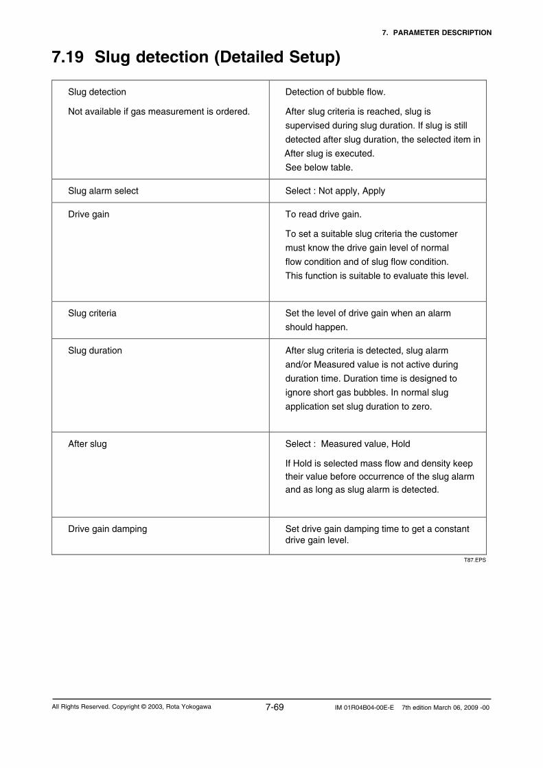
7. PARAMETER DESCRIPTION
7-69 IM 01R04B04-00E-E 7th edition March 06, 2009 -00All Rights Reserved. Copyright © 2003, Rota Yokogawa
7.19 Slug detection (Detailed Setup)
Slug detection
Not available if gas measurement is ordered.
Detection of bubble flow.
After slug criteria is reached, slug is
supervised during slug duration. If slug is still
detected after slug duration, the selected item in
After slug is executed.
See below table.
Slug alarm select Select : Not apply, Apply
Drive gain To read drive gain.
To set a suitable slug criteria the customer
must know the drive gain level of normal
flow condition and of slug flow condition.
This function is suitable to evaluate this level.
Slug criteria Set the level of drive gain when an alarm
should happen.
Slug duration After slug criteria is detected, slug alarm
and/or Measured value is not active during
duration time. Duration time is designed to
ignore short gas bubbles. In normal slug
application set slug duration to zero.
After slug Select : Measured value, Hold
If Hold is selected mass flow and density keep their value before occurrence of the slug alarm and as long as slug alarm is detected.
Drive gain damping Set drive gain damping time to get a constantdrive gain level.
T87.EPS

7. PARAMETER DESCRIPTION
7-70IM 01R04B04-00E-E 7th edition March 06, 2009 -00 All Rights Reserved. Copyright © 2003, Rota Yokogawa
time
mass flow
drive gain
density
single bubble
slug flow
duration time
mass flow, if Hold
mass flow, if Measured value
T88.EPS
Influence of slug on mass flow, density and drive gain :
Gas application?
Yes No
Slug detection off
Slug alarm select = Apply?
Yes No
Drive gain > Slug criteria?
Slug detection off
Yes No
Duration active?
Yes After duration
Function active Alarm off
Measurement continued
Slug detection OnAlarm on
Measurement continued
or value hold
Slug detection offAlarm off

7. PARAMETER DESCRIPTION
7-71 IM 01R04B04-00E-E 7th edition March 06, 2009 -00All Rights Reserved. Copyright © 2003, Rota Yokogawa
7.20 Empty pipe detection (Detailed Setup)Empty pipe detect
Not available if gas measurement (option /GA) is ordered
Detection of empty pipe
After Empty pipe crit is reached, alarm output is activated if selected.
This function can also be used to detect tube failure (see chapter 8.8).
Empty pipe alm sel Select: Not apply, Apply
Empty pipe crit Set density value when empty pipe should happen. If Empty pipe crit is smaller than Density URV, alarm appears if density is lower than Empty pipe crit.If Empty pipe crit is equal or greater than Density URV, alarm appears if density is higher than Empty pipe crit.
After empty pipe Select the behaviour of the outputs after Empty pipe has happened.
Select: Massflow = Zero, Measured Value, Hold
With this function the outputs can be set to zero if the detector runs empty during maintenance. It is also useful for batching if the batch starts with an empty pipe. In such case please install the detector vertically.
Gas application?
Yes No
Empty pipe alm sel = Apply?
Yes No
Empty pipe crit < Density URV? Empty pipe crit ≥ Density URV?
Yes No Yes No
Empty pipe OFF
Alarm off
Empty pipe ON
Alarm Onif density <
empty pipe crit
Outputs either Measured
Value, Hold or 4mA/0Hz
Empty pipe OFF
Alarm off
Empty pipe ON
Alarm Onif density ≥
empty pipe crit
Outputs either Measured
Value, Hold or 4mA/0Hz
Empty pipe OFF
Alarm off
Empty pipe OFF
Alarm off
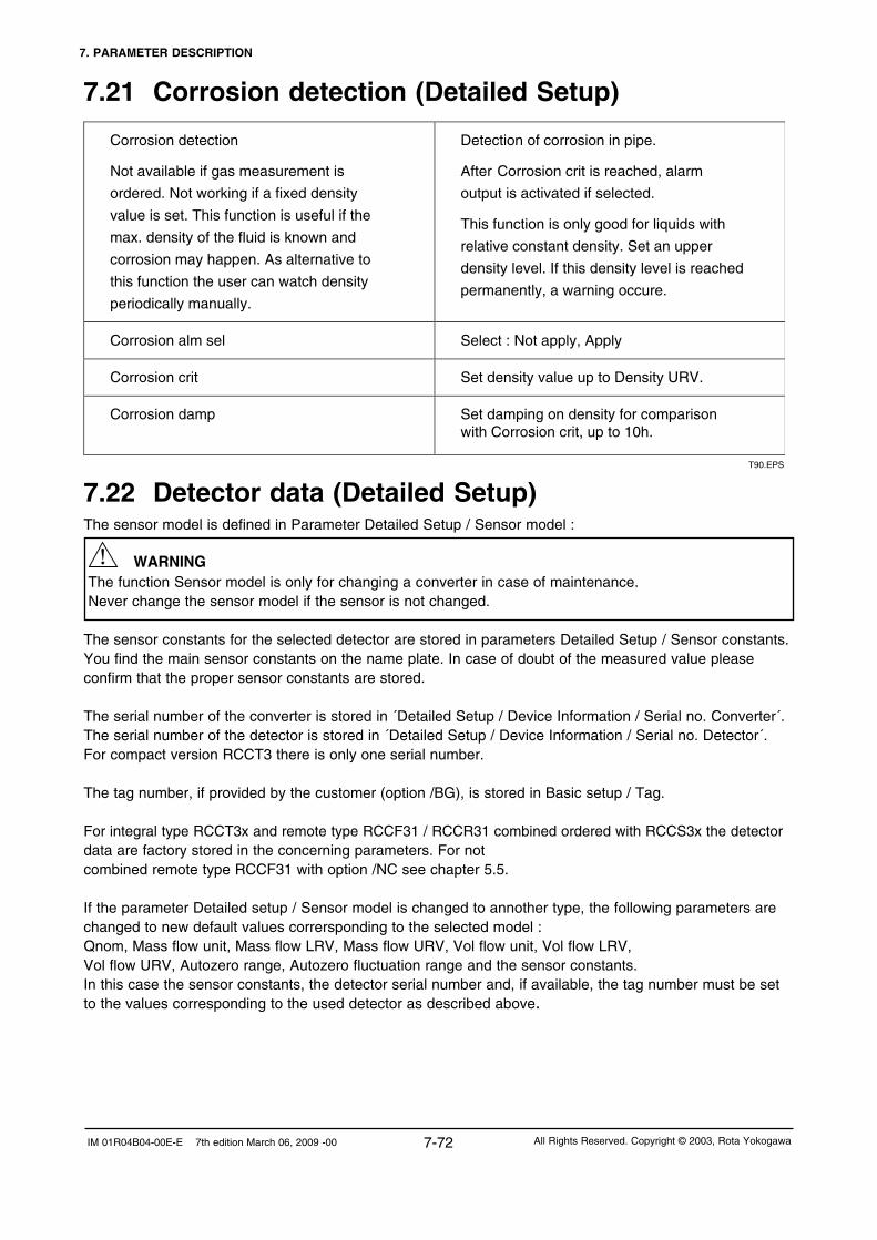
7. PARAMETER DESCRIPTION
7-72IM 01R04B04-00E-E 7th edition March 06, 2009 -00 All Rights Reserved. Copyright © 2003, Rota Yokogawa
7.21 Corrosion detection (Detailed Setup)
Corrosion detection
Not available if gas measurement is
ordered. Not working if a fixed density
value is set. This function is useful if the
max. density of the fluid is known and
corrosion may happen. As alternative to
this function the user can watch density
periodically manually.
Detection of corrosion in pipe.
After Corrosion crit is reached, alarm
output is activated if selected.
This function is only good for liquids with
relative constant density. Set an upper
density level. If this density level is reached
permanently, a warning occure.
Corrosion alm sel Select : Not apply, Apply
Corrosion crit Set density value up to Density URV.
Corrosion damp Set damping on density for comparisonwith Corrosion crit, up to 10h.
T90.EPS
7.22 Detector data (Detailed Setup)The sensor model is defined in Parameter Detailed Setup / Sensor model :
The function Sensor model is only for changing a converter in case of maintenance. Never change the sensor model if the sensor is not changed.
The sensor constants for the selected detector are stored in parameters Detailed Setup / Sensor constants.You find the main sensor constants on the name plate. In case of doubt of the measured value please confirm that the proper sensor constants are stored.
The serial number of the converter is stored in ´Detailed Setup / Device Information / Serial no. Converter´.The serial number of the detector is stored in ´Detailed Setup / Device Information / Serial no. Detector´.For compact version RCCT3 there is only one serial number.
The tag number, if provided by the customer (option /BG), is stored in Basic setup / Tag.
For integral type RCCT3x and remote type RCCF31 / RCCR31 combined ordered with RCCS3x the detector data are factory stored in the concerning parameters. For not combined remote type RCCF31 with option /NC see chapter 5.5.
If the parameter Detailed setup / Sensor model is changed to annother type, the following parameters are changed to new default values corrersponding to the selected model :Qnom, Mass flow unit, Mass flow LRV, Mass flow URV, Vol flow unit, Vol flow LRV, Vol flow URV, Autozero range, Autozero fluctuation range and the sensor constants.In this case the sensor constants, the detector serial number and, if available, the tag number must be set to the values corresponding to the used detector as described above.
WARNING

7. PARAMETER DESCRIPTION
7-73 IM 01R04B04-00E-E 7th edition March 06, 2009 -00All Rights Reserved. Copyright © 2003, Rota Yokogawa
7.23 Autozero (Diag/Service)
Autozero
Mass flow Zero setting.
Please set Zero under process conditions afterwarming up the converter.
Zero tuning Select : Inhibit, Enable
Autozero time Select : 3 min , 30 sec
Select the duration of autozero performing.Recommended: 3 min
Autozero Exe Select : Execute, Not Execute.
If Execute is selected Autozero isstarted. After autozero execution the autozerovalue is indicated and the actual date should be entered (format : mm/dd/yy/yy). Pressing SET stores value, date, temperatureand density in autozero history.
Autozero value
Result of autozero
Autozero check: Autozero history
Indicates 5 latest autozero values with date ofexecution, temperature and density duringexecution (only if date has been entered).
This function allows checking the qualityof autozero condition and long terming zerodrift, if happen.
Autozero check : Autozero initial Indicates the factory autozero value
Autozero check: Autozero range Indicates the typical max. autozero
range. If this range is exceeded during
autozero the warning W06 is generated.
Check the detector installation !
Autozero check: Autozero fluctuation range
Warning: If the sensor model is changed
Autozero fluctuation is zero. Then always a
warning is generated after performing Autozero.
Indicates the factory Autozero fluctuation range determined during calibration. If this range is exceeded during autozero the warning W07 is generated. Check the electrical installation, the plant vibration and the density (is the detectorfully filled?)
T91.EPS

7. PARAMETER DESCRIPTION
7-74IM 01R04B04-00E-E 7th edition March 06, 2009 -00 All Rights Reserved. Copyright © 2003, Rota Yokogawa
IMPORTANT - Stop flow before starting autozero. - During autozero time - Analog output are fixed to 4 mA - Pulse outputs are fixed to zero - Totalizer stops counting - Display keys do not work - In HART communication write- and exe- commands are not accepted - Status input does not work
Additional information and how to start autozero and how to read autozero history is described in chapter 5.6 "Zero adjustment".
7.24 Reading maximum fluid temperature (Detailed Setup)
Fluid max. temp The highest measured medium temperature can be read in this parameter.This parameter can not be reset or changed by the user.
7.25 Option /GA for Gas MeasurementThis option is factory set by order. If this function is selected find the following restrictions: - Density measurement is not available; the reference density value is always used and displayed. - Normal volume flow: - Set reference density to normal density. - Select normal volume (flow) units for volume, total volume, pulse output. - Standard volume flow: - Set reference density to standard density. - Select standard volume (flow) units for volume, total volume, pulse output. - Volume flow: - Set reference density to actual density. - Select volume (flow) units for volume, total volume, pulse output. - Corrosion detection is not available. - Empty pipe detection is not available. - Slug detection is not available
The instrument is mass balanced with air at normal pressure. It can be used for liquids with reduced accuracy.
The minimum URV-LRV range for mass flow, volume flow and net flow is 1% of Qnom.
If Heat of Combustion unit is changed between mass related units (MJ/kg, Btu/lb) and volume related units (MJ/Ncum, Btu/Scuft), there is no conversion of Heat of Combustion value.In this case, Heat of Combustion has to be set manually to the correct value.

8. SELF-DIAGNOSTIC AND TROUBLESHOOTING
8-1 IM 01R04B04-00E-E 7th edition March 06, 2009 -00All Rights Reserved. Copyright © 2003, Rota Yokogawa
8.1 Error descriptions and countermeasureThe self check function displays instrument errors, warnings and alarms.When an alarm or error occurs, the code (e.g. E-01) and the name (e.g. Frequency fault) appear on the display during display mode, alternating with measuring value indication. This does not happen in parameter setting mode.Warnings W-01 to W-04 are indicated in the 4th display line. Warning W-06 and W-07 are indicated directly after autozero if generated. The alarms, errors and warnings are written into history, see chapter 9.2.The following table shows the possible alarms, warnings and error with the concerning influences on outputs and fields variables.
Flow on display
Density, Temp. on display
Totalizeron display
Analog outputs
Frequ./Pulse outputs
Alarm (A); Warning
(W); Error (E)
Name
nc = no change
Status outputs *)
A-01 MF 1 criteria nc nc nc nc nc Mass flow alm 1*)
A-02 MF 2 criteria nc nc nc nc nc Mass flow alm 2*)
A-03 MV 1 criteria nc nc nc nc nc Vol flow alm 1*)
A-04 VF 2 criteria nc nc nc nc nc Vol flow alm 2*)
A-05 Dens 1 criteria nc nc nc nc nc Density alm 1*)
A-06 Dens 2 criteria nc nc nc nc nc Density alm 2*)
A-07 Temp 1 criteria nc nc nc nc nc Temp alm 1*)
A-08 Temp 2 criteria nc nc nc nc nc Temp alm 2*)
A-09
A-10
A-11
A-12
A-13 Total thr exceed
nc nc hold; continue 1)
nc nc Total switch*)
A-14 Slug Detection MFL: meas.; hold 4)
nc nc nc nc Slug alarm*)
A-15 Empty pipe det.
MFL: meas.; hold; 0 2)
nc nc nc nc Empty pipe alm*)
A-16 Corrosion det. nc nc nc nc nc Corrosion alm*)
W-01 Density low
nc DEN: 0.3 kg/l 5)
nc nc nc nc
W-02 Fixed dens act. nc DEN: fix value nc nc nc nc
W-03 Fixed temp act.
nc TEM: fix value nc nc nc nc
W-04 Fixed MF active MFL: fix value
+ act. zero nc nc nc nc nc
W-05 Autozero running nc nc nc nc nc nc
W-06 AZ val error nc nc nc nc nc nc
W-07
nc nc nc nc nc nc
Conc meas alm 1*)
Conc meas alm 2*)
Net flow alm 1 *)
Net flow alm 2*)
Net Flow 1 crit.
Conc 1 criteria
Net Flow 2 crit.
Conc 2 criteria
nc nc nc nc
nc nc nc nc nc
nc nc nc nc nc
nc nc nc nc nc
nc
AZ fluct error
8. Self-diagnostic and Troubleshooting

8. SELF-DIAGNOSTIC AND TROUBLESHOOTING
8-2IM 01R04B04-00E-E 7th edition March 06, 2009 -00 All Rights Reserved. Copyright © 2003, Rota Yokogawa
W-08 Sensor simul. nc nc nc nc nc nc
W-09 Fixed Prim Out nc nc nc 4 mA nc nc
W-10 Prim Out sat. nc nc nc nc nc nc
W-11 Sec Out sat.
nc nc nc nc nc nc
W-12 Tert Out sat. nc
nc
nc
nc
nc
nc
W-13 Quart Out sat.
nc
nc
nc
nc
nc
nc
E-01 Frequency Fault nc 3,6 mA;…3) nc nc
E-02 Signal Fault nc 3,6 mA;…3) nc nc
E-03 EEPROM Fault nc 3,6 mA;…3) nc nc
E-04 CPU Fault nc 3,6 mA;…3) nc nc
E-05 DSP Fault nc 3,6 mA;…3) nc nc
E-06 Sensor 1 Signal Fault nc 3,6 mA;…3) nc nc
E-07 Sensor 2 Signal Fault
nc 3,6 mA;…3) nc nc
E-08 Temperature Sensor fault nc 3,6 mA;…3) nc nc
Warning (W)
Error (E)
Name
nc = no change nd = not defined
nd
nd
nc
nd
nd
nc
nc
ncDensity = faultyTemp = 30°C
Flow on display
Density, Temp. on display
Totalizeron display
Analog outputs
Frequ./Pulse outputs
Status outputs *)
Density = 0Temp = nc
nc
nc
nd
Density = 0Temp = nc
nc
nc
1) Choice of “Total at alarm” (Detailed Setup / Totalizer)2) Choice of “Output after Empty pipe” (Detailed Setup / Empty pipe detect)3) Choice of “Analog 1 alarm out” or "Analog 2 alarm out” (Detailed Setup / Config Output) and NAMUR / NOT NAMUR (Measuring range)4) Choice of “After Slug” (Detailed Setup / Slug detection)5) Only if “Liquid” is selected (Detailed Setup / Liquid/gas selection)*) Status outputs acc. SO 1 or SO 2 function and SO 1 or SO 2 active mode
The following table shows possible countermeasures :
Alarm (A); Warning (W);
Error (E) Name Description Countermeasure
A-01 Mass flow L Alarm Mass flow below Mass flow LRV Increase mass flow / Change setting
A-02 Mass flow H Alarm Mass flow above Mass flow URV Reduce mass flow / Change setting
A-03 Vol flow L Alarm Volume flow below Vol flow LRV Increase volume flow / Change setting
A-04 Vol flow H Alarm Volume flow above Vol flow URV Reduce volume flow / Change setting
A-05 Density L Alarm Density below Density LRV Increase density / Change setting
A-06 Density H Alarm Density above Density URV Reduce density / Change setting
A-07 Temperature L Alarm Temp. below Temp LRV Increase temperature / Change setting
A-08 Temperature H Alarm Temp. above Temp URV Reduce temperature / Change setting
A-09
A-10
A-11
A-12
T83.EPS
Net Flow L Alarm
Concentration L Alarm
Net Flow H Alarm
Concentration H Alarm
Concentration below Conc LRV
Concentration above Conc URV
Net flow below Net flow LRV
Net flow above Net flow URV
Increase net flow / Change setting
Reduce net flow / Change setting
Increase concentration / Change setting
Reduce concentration / Change setting

8. SELF-DIAGNOSTIC AND TROUBLESHOOTING
8-3 IM 01R04B04-00E-E 7th edition March 06, 2009 -00All Rights Reserved. Copyright © 2003, Rota Yokogawa
A-13 Total threshold exceed Totalizer value exceeds total threshold Reset totalizer / Change setting
A-14 Slug Detection Slug criterion is reached Reduce gas bubbles in medium
A-15 Empty Pipe Detection Empty pipe criterion is reached Fill pipe
A-16 Corrosion Detection Corrosion criterion is reached Change detector
W-01 Density lower 0.3kg/l Density lower than 0.3 kg/l Fill the detector with fluid
W-02 Fixed Dens selected Parameter Dens fix val sel is enable Set Parameter Dens fix val sel to inhibit
W-03 Fixed Temp selected Parameter Temp fix val sel is enable
Set Parameter Temp fix val sel to inhibit
W-04 Fixed Mass flow selected Parameter MF fix val sel is enable Set Parameter MF fix val sel to inhibit
W-05 Autozero running …..
W-06 Autozero value out of range
Autozero value is out of the internal detector depending range
Stop flow during auto zero. Check detector installation.
W-07 Autozero fluctuation out of range
Autozero fluctuation is out of the internal detector depended range
Stop flow during auto zero Check electrical installation, vibrations and density.
W-08 Sensor Simulation active Fixed frequency or fixed phase difference is enabled
Set sensor simulation to inhibit
W-09 Analog output 1 fixed Analog output 1 fixed at 4 mA for multidrop operation
Set HART polling address to 0 (Multidrop operation stops)
W-10 Analog output 1 saturated Analog output 1 reaches less than 3.8 mA or more than 20.5 mA
Increase or decrease current level of output 1
W-11 Analog output 2 saturated Analog output 2 reaches less than 3.8 mA or more than 20.5 mA
Increase or decrease current level of output 2
W-12 Pulse/Status output 1 saturated
Relation between Pulse width and pulse rate of Pulse/Status output 1 is to high
Decrease length of pulse width or increase amount of pulse rate of pulse output 1
W-13 Pulse/Status output 2 saturated
Relation between Pulse width and pulse rate of Pulse/Status output 2 is to high
Decrease length of pulse width or increase amount of pulse rate of pulse output 2
E-01 Frequency Fault Driving frequency out of range Check cable (Remote) and detector
E-02 Signal Fault Phase difference out of range Check cable (Remote) and detector
E-03 EEPROM Fault Contact Yokogawa service
E-04 CPU Fault Contact Yokogawa service
E-05 DSP Fault Contact Yokogawa service
E-06 Sensor 1 Signal Fault Sensor 1 signal below 7% for 3 min. Check cable (Remote) and detector
E-07 Sensor 2 Signal Fault Sensor 2 signal below 7% for 3 min. Check cable (Remote) and detector
E-08 Temperature Sensor fault T<-210°C or T>450°C Check cable (Remote) and detector Check temperature
T84.EPS
CRC-Error

8. SELF-DIAGNOSTIC AND TROUBLESHOOTING
8-4IM 01R04B04-00E-E 7th edition March 06, 2009 -00 All Rights Reserved. Copyright © 2003, Rota Yokogawa
8.2 Reading Event + Error History (Diag/Service, Self test/Status)
Event Overview /
Error
Alarm
Warning
Reads the actual errors, alarms and
warnings (EAW). In Event Overview the
number of the actual EAWs is shown. In
Error , Alarm or Warning the description
of the actual events can be found.
H ist Overview in Order Shows the latest 10 EAWs. By comparing
this with Hist Overview abs it can be checked
if certain EAWs have vanished.
H ist Overview in Order /
Clear History
Select: Execute, Non execute
If Executev is selected the latest 10 EAWs
are cleared.
Hist Overview abs /
Error
Alarm
Warning
In Hist Overview abs the number of
EAWs after the last clearance can be
viewed. In Error, Alarm or Warning the
description of the events after the last
clearance can be found.
Hist Overview abs /
Clear History
Select : Execute, Not Execute
If Execute is selected the user is asked
to fill in a date (mm/dd/yyyy). If a date is
set the errors and warnings are stored in
the Error history with this date.
Error History
In Error History the number of EAWs of
the last clearance of the Hist Overview abs
can be viewed. In Error or Warning the
description of the events can be found.
The last 10 entries can be selected by date.
T85.EPS

8. SELF-DIAGNOSTIC AND TROUBLESHOOTING
8-5 IM 01R04B04-00E-E 7th edition March 06, 2009 -00All Rights Reserved. Copyright © 2003, Rota Yokogawa
8.3 Self test (Diag/Service)
Self test/Status Select : Self test, Status
If Self test is selected, all error and alarm status
are checked.
If Status is selected, the existing errors and
alarms are indicated in succession. T86.EPS
8.4 Signal- and I/O-Test (Diag/Service)Input/Output test
These functions enable you to simulate the
I/O signals (loop test). The outputs can be
checked with a multimeter.
Refer to the connecting diagrams in chapter 4.8.3.
The test can be cancelled by pressing any key.
Analog output 1
Analog output 2
Pulse output 1
Status output 1
Pulse output 2
Status output 2
Status input
Setting range : 2.4 to 21.6mA
Setting range : 2.4 to 21.6mA
Setting range : 0 to 10000Hz
Setting range : ON or OFF
Setting range : 0 to 2000Hz
Setting range : ON or OFF
Setting range : OPEN or SHORT
T87.EPS
8.5 Output trimOutput trim With this function the 4mA and the 20mA can be
adjusted to compensate aging drifts.
AO 1 trim 4mA / AO 1 trim 20mA
AO 2 trim (same as AO 1 trim)
The analog output 1 is set to the internal 4mA or 20mA value. Connect a load resistor between 20 and 600 W and measure the current.This current value must be entered on request on display. The deviation to 4mA is corrected by theconverter itself.
T88.EPS

8. SELF-DIAGNOSTIC AND TROUBLESHOOTING
8-6IM 01R04B04-00E-E 7th edition March 06, 2009 -00 All Rights Reserved. Copyright © 2003, Rota Yokogawa
8.6 Detector cleaning
CAUTION For integral type : Ambient temperature may not exceed 55°C !
The equipment can be CIP-cleaned. Steam below 230°C is not a problem. However, you should take care that the cleaning operation does not last so long that the converter temperature exceed 55°C. Switch power off during cleaning.
8.7 Troubleshooting
IMPORTANT If the indicated countermeasures do not remedy the fault or in case of troubles which can not be remedied by the user, please contact your Yokogawa service centre.
If there is an error, alarm or warning displayed, deal with the error according to 8.1 „Error descriptions and countermeasure”.In the following some problems are listed which may not be indicated as error, alarm or warning. First make sure, that no error, alarm or warning is displayed.
8.7.1 No indication
no yes yes no yes yes
Is the power supply voltage between terminals L/+ and N/- correct ?
Check the power supply connections.
Is display cable connected correct to CPU board ?
Connect the cable in the correct position.
Contact the nearest YOKOGAWA office or service center.
F81.EPS

8. SELF-DIAGNOSTIC AND TROUBLESHOOTING
8-7 IM 01R04B04-00E-E 7th edition March 06, 2009 -00All Rights Reserved. Copyright © 2003, Rota Yokogawa
8.7.2 No Key-setting possible
8.7.3 No HART communication
no yes no yes
Is parameter Key Status set enable ?
Set parameter Key Status enable .
Is display cable connected correct to CPU board ?
Connect the cable in the correct position.
Contact the nearest YOKOGAWA office or service center.
F82.EPS
no yes no yes
Is HART DD of Rotamass RCCT3 available in HART communicator ?
Store necessary DD in HART communicator.
Is HART communicator connected to Rotamass according chapter 4.8.4 ?
Connect HART communicator according chapter 4.8.4.
Contact the nearest YOKOGAWA office or service center.
F83.EPS

8. SELF-DIAGNOSTIC AND TROUBLESHOOTING
8-8IM 01R04B04-00E-E 7th edition March 06, 2009 -00 All Rights Reserved. Copyright © 2003, Rota Yokogawa
8.7.4 Unstable zero
no
yes
yes
no
no
yes
no
Is the tube filled with liquid completely (check the density)?
Fill the detector. May be vertical installation is indicated.
Are bubbles in the liquid ? Check piping and installation.
Is the detector installed free of mechanical stress?
Is electrical grounding correct according chapter 4.8.1; 4.8.2; 9 ?
Make correct grounding.
Is the flowmeter located near motors, transformers or other electric equipments ?
Shield the flowmeter sufficiently. Locate the flowmeter as far as possible from these equipments.
Is the connection box free of dirt and humidity? (only for remote installation)
yes
no
Loose the process connections and make sure that they are in line. Support only one adjacent pipe, let one side of the adjacent pipe be “soft”.
yes
Contact the nearest YOKOGAWA office or service center.
yes
no Clean and dry the connection box. Make sure that humidity cannot penetrate.
F84.EPS
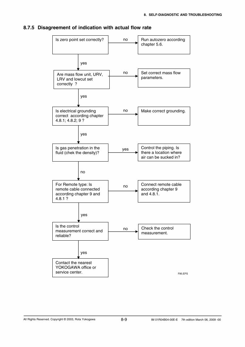
8. SELF-DIAGNOSTIC AND TROUBLESHOOTING
8-9 IM 01R04B04-00E-E 7th edition March 06, 2009 -00All Rights Reserved. Copyright © 2003, Rota Yokogawa
8.7.5 Disagreement of indication with actual flow rate no yes no yes no yes no no no
Run autozero according chapter 5.6.
Are mass flow unit, URV, LRV and lowcut set correctly ?
Set correct mass flow parameters.
Contact the nearest YOKOGAWA office or service center.
Is electrical grounding correct according chapter 4.8.1; 4.8.2; 9 ?
Make correct grounding.
Control the piping. Is there a location where air can be sucked in?
Connect remote cable according chapter 9 and 4.8.1.
Is zero point set correctly?
Is gas penetration in the fluid (chek the density)?
yes
Is the control measurement correct and reliable?
For Remote type: Is remote cable connected according chapter 9 and 4.8.1 ?
yes
yes
Check the control measurement.
F85.EPS

8. SELF-DIAGNOSTIC AND TROUBLESHOOTING
8-10IM 01R04B04-00E-E 7th edition March 06, 2009 -00 All Rights Reserved. Copyright © 2003, Rota Yokogawa
8.7.6 Disagreement of indication with actual density no yes yes no no yes no yes no yes yes no yes no
Set correct density parameters.
Change piping . Vertical installation is recommended. Check installation.
Connect remote cable according chapter 9 and 4.8.1.
Make troubleshooting according chapter 8.7.7.
Set Density fix val sel = Inhibit.
Is temperature measurement correct ?
For Remote type: Is remote cable connected according chapter 9 and 4.8.1 ?
Let YOKOGAWA perform a new density and mass flow calibration.
Has corrosion or errosion occured (too high density reading)? Contact the nearest YOKOGAWA office or service center.
Is fixed density selected (Density fix val sel = Enable ) ?
Is the tube filled with liquid completely and without bubbles (density low reading)?
Is there sediment orclogging in the tubes ?
Clean the tubes by means like water, steam or other solvent.
Are density unit, URV, LRV and lowcut set correctly ?
F86.EPS

8. SELF-DIAGNOSTIC AND TROUBLESHOOTING
8-11 IM 01R04B04-00E-E 7th edition March 06, 2009 -00All Rights Reserved. Copyright © 2003, Rota Yokogawa
8.7.7 Disagreement of indication with actual temperature
yes
Are temperature unit, URV, LRV and lowcut set correctly ?
Set correct temperature parameters.
PT 100 fault. Simulate the correct temp. by a fixed temp, value or connect an external PT100.
For Remote type: Is remote cable connected according chapter 9 and 4.8.1 ?
Connect remote cable according chapter 9 and 4.8.1.
Compact type: disconnect first the converter housing Disconnect the temperature sensor cables 7,8,9 from TP1, TP2, TP3 in detector RCCS3x terminal box. Measure the resistances of detector temperature sensor terminals TP1, TP2, TP3. Resistance between TP1 + TP2 : 50 …200 depending on medium temperature Resistance between TP1 + TP3 : 50 …200 depending on medium temperature Resistance between TP2 + TP3 : <10
Replace remote cable.
Is fixed temperature selected (Tempy fix val sel = Enable ) ?
Set Temp fix val sel = Inhibit.
Resistance values are as stored ?
For remote type: Check remote cable lines 7, 8, 9. Cable OK ?
yes
no
no
no
no
no
yes
yes
yes
yes
F87.EPS
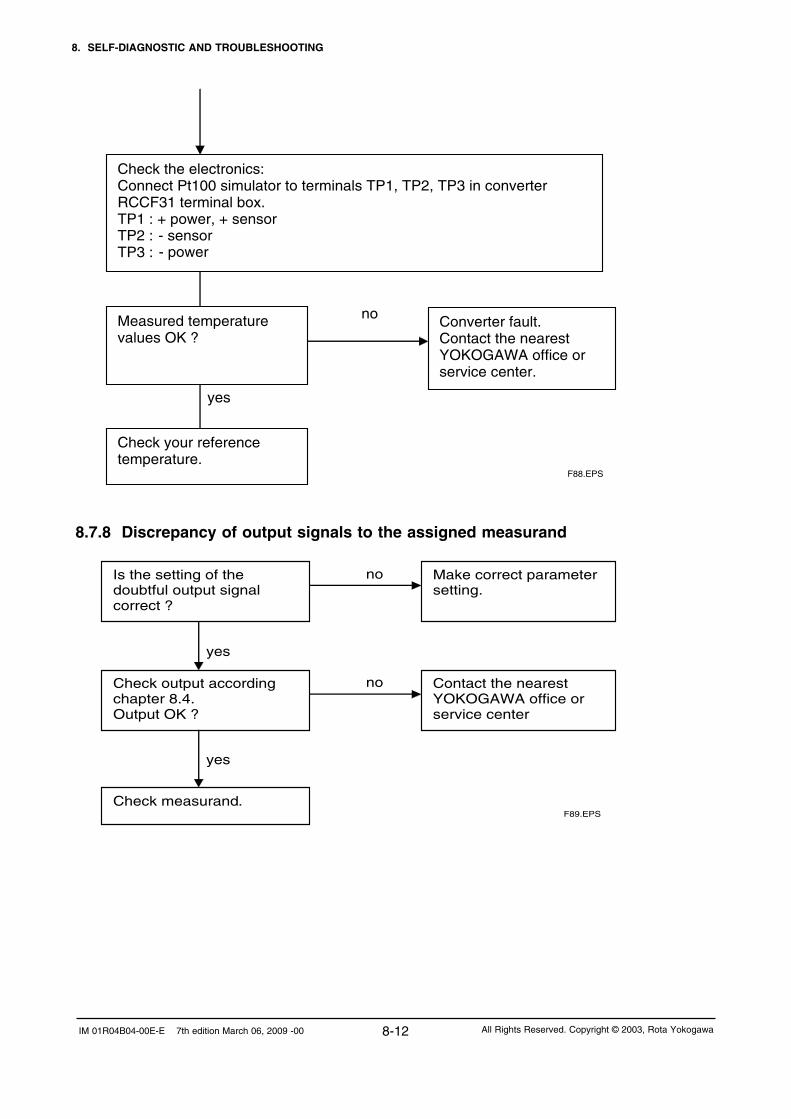
8. SELF-DIAGNOSTIC AND TROUBLESHOOTING
8-12IM 01R04B04-00E-E 7th edition March 06, 2009 -00 All Rights Reserved. Copyright © 2003, Rota Yokogawa
8.7.8 Discrepancy of output signals to the assigned measurand
no
yes
Measured temperature values OK ?
Converter fault. Contact the nearest YOKOGAWA office or service center.
Check the electronics: Connect Pt100 simulator to terminals TP1, TP2, TP3 in converter RCCF31 terminal box. TP1 : + power, + sensor TP2 : - sensor TP3 :
Check your reference temperature.
F88.EPS
- power
no
yes
no
yes
Is the setting of the doubtful output signal correct ?
Make correct parameter setting.
Check output according chapter 8.4. Output OK ?
Contact the nearest YOKOGAWA office or service center
Check measurand. F89.EPS

8. SELF-DIAGNOSTIC AND TROUBLESHOOTING
8-13 IM 01R04B04-00E-E 7th edition March 06, 2009 -00All Rights Reserved. Copyright © 2003, Rota Yokogawa
8.7.9 Setting "Burn-out" modeThe flowmeter is equipped with a CPU error burn-out function used to set the analog output direction upon CPU error. When factory-shipment the output of CPU error burn-out is set to HIGH. The setting of the direction of analog output from burn-out can be changed.
To change the direction of output arising from burn-out, switch the jumper J2 on the CPU Board (see figure below).
CPU Board
Cable to display
JP2 (Burn out)
High : I ≥ 21.6mA
Low : I ≤ 3.6mA
F810.EPS

8. SELF-DIAGNOSTIC AND TROUBLESHOOTING
8-14IM 01R04B04-00E-E 7th edition March 06, 2009 -00 All Rights Reserved. Copyright © 2003, Rota Yokogawa
The ROTAMASS RCCx34 ... 39/XR was tested and FM- approved according to ANSI/ISA – 12.27.01 – 2003 for Canadian Dual Seal Approval. For units with option /DS this is stated on the name plate.
NOTE
If ROTAMASS flowmeter is not used in Canada this functionality can also be used without Dual Seal approval.
The primary seal (metering tube) and the secondary seal withstand the maximum test pressures forced for the maximum flange pressure of 12.41 MPas / 1800 psi (Flange A4, ASME 900). However the enclosure do not withstand this pressure. For details see GS 01R04B04-00E-E.
When the metering tube fails, the detector enclosure is filled with process medium and the density increas-es rapidly. This can be used for detecting a primary seal failure by the following annunciation methods:
A) Via too high density reading, preferable with liquid application- Set “Basic setup / Density / Density URV about 0.3 kg/l above the highest possible process density. - Set an output (current or frequency) to density transmission.- If the URV is reached (e.g. 20 mA ) the primary seal failed.
B) Via Status output and “Empty pipe detection”Only for liquid (only possible with software version 1.7 or higher):- Check parameter "Basic Setup / Density / Density URV" (Default value is 1.5 kg/l). URV should be about 0.3 kg/l higher than any density the process can provide.- Set parameter "Detailed Setup / Empty pipe detect / Empty pipe alm sel / Apply".- Set parameter "Detailed Setup / Empty pipe detect / Empty pipe crit / ..." to a value which is a little bit higher than Density URV.- For detection with e.g. status output 1: Set "Detailed Setup / Config Output/Input / Pulse/Status out 1 / Pulse/Stat 1 select / Status out". Set "Detailed Setup / Config Output/Input / Pulse/Status out 1 / SO1 function / Empty alarm"- When the metering tube fails, the detector housing is filled with the process medium and the density increases. Alarm A15 "Empty pipe detection" appears, display is blinking and the status output is set active.
C) Via rupture disk (option /RD), preferable with gas application- When the metering tube fails, the installed rupture disk bursts at about 20 bar (290 psi). - For gas application the result will be a whistle by the gas blowing out.- Rupture disk is only for annunciation.
WARNING If rupture disk bursts, the hazardous process medium is pressed out of the detector housing to the environment. Take care that no worker gets contact to the medium.
8.8 Detection of metering tube failure

9. EXPLOSION PROTECTED TYPE INSTRUMENTS
9-1 IM 01R04B04-00E-E 7th edition March 06, 2009 -00All Rights Reserved. Copyright © 2003, Rota Yokogawa
9. Explosion protected type instruments9.1 ATEXIn this section, further requirements and differ-
ences for explosion proof type
instrument are described. For explosion proof type
instrument, the description in this chapter is prior
to other description in this Instruction Manual.
Only trained persons may use the
instrument in industrial location.
WARNING
ROTAMASS is produced by
Rota Yokogawa
Rheinstr. 8
D-79664 Wehr
Germany
9.1.1 Technical Data
Applicable standards:EN 60979-0: 2006; EN 60079-1: 2007; EN 60079-7: 2007; EN 60079-11:2007; EN 61241-0: 2006; EN 60241-1: 2004;EN 61241-11: 2006
Remote detector RCCS30 ... 39/XR (option /KS1):- KEMA 01ATEX 1075 X- Intrinsically safe- II 2G Ex ib IIB/IIC T1 ... T6- II 2D Ex ibD 21 IP6x Txxx (xxx = max. surface temperature see below)-Max. surface temperature : Standard : 150°C /MT : 220°C /HT : 350°C - Degree of protection : IP67- Ambient humidity : 0 to 95% RH- Ambient temperature rangeStandard and option /MT: -50°C to +80°COption /HT (process temperature < 280°C): : -50°C to +65°COption /HT (process temperature < 350°C: : -50°C to +55°C- Process temperature limits : Standard : -50°C to 150°C Option /MT: : -50°C to 220°C Option /HT : 0°C to 350°C- Heat carrier fluid temperature limits : Standard : -50°C to 150°C Option /MT: : -50°C to 220°C Option /HT : 0°C to 350°C
Remote converter RCCF31 (option /KF1):- KEMA 02ATEX 2183 X- Flame proof with intrinsic safe connection to detector (ib)- II 2G Ex d(e) [ib] IIC T6- II 2G Ex d(e) [ib] IIB T6 with option /HP- II 2D Ex tD [ibD] A21 IP6x T70°C- Max. surface temperature: 70°C- Degree of protection : IP67- Power supply : 90 to 250 V AC, 50/60 Hz 20.5 to 28.8 V DC- Power consumption : max. 25 VA / 10 W- Ambient humidity : 0 to 95% RH
- Ambient temperature range: -20°C to +50°C
Remote converter RCCF31 (option /KF2):- KEMA 02ATEX 2183 X- Flame proof with intrinsic safe connection to detector (ib)- Additional intrinsic safe outputs.- II 2G Ex d(e) [ia] [ib] IIC T6- II 2G Ex d(e) [ia] [ib] IIB T6 with option /HP Protection [ia] refers to the intrinsic safe outputs. Protection [ib] refers to the connection to the
detector.- II 2D Ex tD [ibD] A21 IP6x T70°C- Max. surface temperature: 70°C- Degree of protection : IP67- Power supply : 90 to 250 V AC, 50/60 Hz 20.5 to 28.8 V DC- Power consumption : max. 25 VA / 10 W- Ambient humidity : 0 to 95% RH- Ambient temperature range : -20°C to +50°C
Remote converter RCCR31 (option /KS1) :- KEMA 02ATEX 2183 X- Associated apparatus with intrinsic safe connection to detector (ib)- II (2)G [Ex ib] IIC - II (2)G [Ex ib] IIB with option /HP- II (2)D [Ex ibD]- Power supply : 90 to 250 V AC, 50/60 Hz 20.5 to 28.8 V DC- Power consumption : max. 25 VA / 10 W- Ambient humidity: 0 to 95% RH- Ambient temperature range: -20°C to +50°C
WARNING Remote rack mount converter RCCR31 must only be installed in safe area !
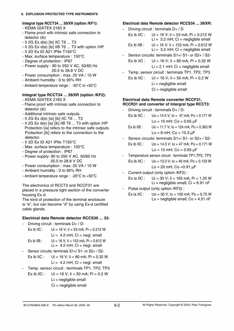
9. EXPLOSION PROTECTED TYPE INSTRUMENTS
9-2IM 01R04B04-00E-E 7th edition March 06, 2009 -00 All Rights Reserved. Copyright © 2003, Rota Yokogawa
Electrical data Remote detector RCCS34 ... 39/XR:- Driving circuit : terminals D+ / D
Ex ib IIC : Ui = 16 V; Ii = 53 mA; Pi = 0.212 W Li = 3.2 mH; Ci = negligible small
Ex ib IIB : Ui = 16 V; Ii = 153 mA; Pi = 0.612 W Li = 3.2 mH; Ci = negligible small
- Sensor circuits: terminals S1+/ S1- or S2+ / S2-
Ex ib IIC : Ui = 16 V; Ii = 80 mA; Pi = 0.32 W
Li = 2.1 mH; Ci = negligible small
- Temp. sensor circuit : terminals TP1, TP2, TP3
Ex ib IIC : Ui = 16 V; Ii = 50 mA; Pi = 0.2 W
Li = negligible small
Ci = negligible small
Electrical data Remote converter RCCF31, RCCR31 and converter of Intergral type RCCT3:- Driving circuit : terminals D+ / D-
Ex ib IIC : Uo = 14.5 V; Io = 47 mA; Po = 0.171 W
Lo = 15 mH; Co = 0.65 µF
Ex ib IIB : Uo = 11.7 V; Io = 124 mA; Po = 0.363 W
Lo = 8 mH; Co = 10.3 µF
- Sensor circuits: terminals S1+/ S1- or S2+ / S2-
Ex ib IIC : Uo = 14.5 V; Io = 47 mA; Po = 0.171 W
Lo = 15 mH; Co = 0.65 µF
- Temperature sensor circuit : terminals TP1,TP2, TP3
Ex ib IIC : Uo = 13.3 V; Io = 40 mA; Po = 0.133 W
Lo = 20 mH; Co =0.91 µF
- Current output (only option /KF2) :
Ex ia IIC : Ui = 30 V; Ii = 165 mA; Pi = 1.25 W Li = negligible small; Ci = 6.91 nF
- Pulse output (only option /KF2) :
Ex ia IIC : Uo = 30 V; Io = 100 mA; Po = 0.75 W Lo = negligible small; Co = 4.51 nF
Integral type RCCT34 ... 39/XR (option /KF1):- KEMA 02ATEX 2183 X- Flame proof with intrinsic safe connection to detector (ib)- II 2G Ex d(e) [ib] IIC T6 ... T3- II 2G Ex d(e) [ib] IIB T6 ... T3 with option /HP- II 2D Ex tD A21 IP6x T150°C- Max. surface temperature : 150°C- Degree of protection : IP67- Power supply : 90 to 250 V AC, 50/60 Hz 20.5 to 28.8 V DC- Power consumption : max. 25 VA / 10 W- Ambient humidity : 0 to 95% RH- Ambient temperature range : -20°C to +50°C
Integral type RCCT34 ... 39/XR (option /KF2):- KEMA 02ATEX 2183 X- Flame proof with intrinsic safe connection to detector (ib)- Additional intrinsic safe outputs.- II 2G Ex d(e) [ia] [ib] IIC T6 ... T3- II 2G Ex d(e) [ia] [ib] IIB T6 ... T3 with option /HP Protection [ia] refers to the intrinsic safe outputs. Protection [ib] refers to the connection to the detector.- II 2D Ex tD A21 IP6x T150°C- Max. surface temperature : 150°C- Degree of protection : IP67- Power supply: 90 to 250 V AC, 50/60 Hz 20.5 to 28.8 V DC- Power consumption : max. 25 VA / 10 W- Ambient humidity : 0 to 95% RH- Ambient temperature range : -20°C to +50°C
The electronics of RCCT3 and RCCF31 are placed in a pressure tight section of the converter housing Ex d. The kind of protection of the terminal enclosure is “e”, but can become “d” by using Ex-d certified cable glands.
Electrical data Remote detector RCCS30 ... 33:- Driving circuit : terminals D+ / D-
Ex ib IIC : Ui = 16 V; Ii = 53 mA; Pi = 0.212 W
Li = 4.2 mH; Ci = negl. small
Ex ib IIB : Ui = 16 V; Ii = 153 mA; Pi = 0.612 W Li = 4.2 mH; Ci = negl. small
- Sensor circuits: terminals S1+/ S1- or S2+ / S2-
Ex ib IIC : Ui = 16 V; Ii = 80 mA; Pi = 0.32 W
Li = 4.2 mH; Ci = negl. small
- Temp. sensor circuit : terminals TP1, TP2, TP3
Ex ib IIC : Ui = 16 V; Ii = 50 mA; Pi = 0.2 W
Li = negligible small
Ci = negligible small

9. EXPLOSION PROTECTED TYPE INSTRUMENTS
9-3 IM 01R04B04-00E-E 7th edition March 06, 2009 -00All Rights Reserved. Copyright © 2003, Rota Yokogawa
Coherence between temperature class, ambient- and medium temperature/
temperature of heat carrier :RCCS30 to RCCS33
without insulationRCCS30 to RCCS33 with factory insulation
Temp. class
Max. ambient temperature
Max. process temperature
Max. ambient temperature
Max. process temperature
T6 50°C / 122°F 60°C / 140°F 60°C / 140°F 60°C / 140°F
T5 50°C / 122°F 80°C / 176°F 80°C / 176°F 90°C / 194°F
T480°C / 176°F50°C / 122°F
100°C / 212°F120°C / 248°F
80°C / 176°F 130°C / 266°F
T3 80°C / 176°F 150°C / 302°F 80°C / 176°F 150°C / 302°F
T2 80°C / 176°F 150°C / 302°F 80°C / 176°F 150°C / 302°F
RCCS34 to RCCS39/XR without insulation
RCCS34 to RCCS39/XR with factory insulation
RCCT34 to RCCT39/XR
Temp. class
Max. ambient temperature
Max. process temperature
Max. ambient temperature
Max. process temperature
Max. ambient temperature
Max. process temperature
T6 40°C / 104°F 40°C / 104°F 65°C / 149°C 65°C / 149°F 50°C / 122°F 65°C / 149°C
T5 55°C / 131°F 55°C / 131°F 75°C / 167°F 75°C / 167°F 50°C / 122°F 80°C / 176°F
T480°C / 176°F40°C / 104°F
100°C / 212°F120°C / 248°F
70°C / 158°F 115°C / 239°F 50°C / 122°F 115°C / 239°F
T380°C / 176°F40°C / 104°F
160°C / 320°F180°C / 356°F
70°C / 158°F 180°C / 356°F 50°C / 122°F 150°C / 302°F
T2 80°C / 176°F 220°C / 428°F 65°C /149°F 275°C / 527°F
T1 45°C / 113°F 350°C / 662°F
For customer insulation of RCCS30 to 39/XR the following must be regarded : The table "with factory insulation" is calculated with 80 mm insulation and k-factor = 0.4 W/m2K. If your insulation data are worse than these use table "without insulation" !
NOTE

9. EXPLOSION PROTECTED TYPE INSTRUMENTS
9-4IM 01R04B04-00E-E 7th edition March 06, 2009 -00 All Rights Reserved. Copyright © 2003, Rota Yokogawa
9.1.2 Installation
Integral type RCCT3
WARNING 1. Ex type of ROTAMASS must be connected to the suitable IS earthing system (see installation diagram). Converter case must have connection to the potential equalisation facility. If the
connecting process tubing is part of the potential equalisation, no additional connection is required . 2. Use the certified cable glands, suitable for the conditions of use. The delivered cable glands are only for
Ex e use. For Ex d use d-type cable glands. 3. Please confirm that the ground terminal (inside the terminal enclosure) is firmly
connected by means of a clip-on eye-let.
Cable glands for power- and I/O-cables :RCCT3x-x xx M : Ex e types are enclosed. These cable glands can also be used for “dust application” (D). Use ATEX-certified Ex d cable glands for Ex d condition.RCCT3x-xxx A : No cable glands are enclosed. Use the ATEX-certified cable glands, suitable for the conditions of use (Ex de or Ex d or dust application).
For “dust application” (D) use cable glands with minimum IP67 protection !
Installation diagram (option /KF1):
L/+N/-G
Power supply
I/O control
Hazardous area Safe area
I/O
Rotamass RCCT3
F91.EPS
Ter
min
al B
ox
Detailed information for connection intrinsic safe outputs (option /KF2) see chapter 4.4.5.

9. EXPLOSION PROTECTED TYPE INSTRUMENTS
9-5 IM 01R04B04-00E-E 7th edition March 06, 2009 -00All Rights Reserved. Copyright © 2003, Rota Yokogawa
Remote field-mount type RCCF31 with RCCS3
WARNING 1. Ex-type RCCF31 and RCCS3 must be connected to the suitable IS earthing system (see installation diagram). Converter and detector case must have connection to the potential equalisation facility. 2. Use the certified cable glands, suitable for the conditions of use. 3. Please confirm that the ground terminal (inside the terminal enclosure) is firmly connected by means of a clip-on eye-let. 4. For EMC technical reasons the case of the detector is connected to the case of the converter via the shielding of the interconnecting cable.
Cable glands for power- and I/O-cables :RCCF31-xxx M : Ex e types are enclosed. These cable glands can also be used for “dust application” (D). Use ATEX-certified Ex d cable glands for Ex d condition.RCCF31-xxx A : No cable glands are enclosed. Use the ATEX-certified cable glands, suitable for the conditions of use (Ex de or Ex d or dust application)
For “dust application” (D) use cable glands with minimum IP67 protection !
Cable glands for detector connection terminal :RCCF31-xxx M : Cable glands are fitted in the concerning thread. This cable gland can be used for “dust application” (D). RCCF31-xxx A : Cable glands are enclosed. This cable gland can also be used for “dust application” (D).
Installation diagram (option /KF1) :
L/+N/-G
Power supply
I/O control
Hazardous area Safe area
I/O
RCCF31RCCS3
D+D-
S1+S1-
S2+S2-
TP1TP2TP3
D+D-
S1+S1-
S2+S2-
TP1TP2TP3
COM
Exclusive remote cable RCCY03
F92.EPS
Ter
min
al B
ox
The inner shields (shields of the cable pairs) are connected together to COM – terminal on converter side.The outer shield of the cable is connected on both sides to the cases by cable gland.
Detailed information for connection intrinsic safe outputs (option /KF2) see chapter 4.4.5.

9. EXPLOSION PROTECTED TYPE INSTRUMENTS
9-6IM 01R04B04-00E-E 7th edition March 06, 2009 -00 All Rights Reserved. Copyright © 2003, Rota Yokogawa
Remote rack-mount type RCCR31 with RCCS3
WARNING 1.. Remote rack-mount converter RCCR31 may only be installed in safe area ! 2. Ex-type RCCR31 and RCCS3 must be connected to the suitable IS earthing system (see installation diagram). Converter and detector case must have connection to the potential equalisation facility. 3. Please confirm that the ground terminal on terminal board is firmly connected. 4. For EMC technical reasons the case of the detector is connected to the case of the converter via the shielding of the interconnecting cable.
Installation diagram :
L/+N/-G
Power supply
I/O control
Hazardous area Safe area
I/O
RCCR31RCCS3
D+D-
S1+S1-
S2+S2-
TP1TP2TP3
D+D-
S1+S1-
S2+S2-
TP1TP2TP3
COM
Exclusive remote cable RCCY03
F93.EPS
Ter
min
al B
oard

9. EXPLOSION PROTECTED TYPE INSTRUMENTS
9-7 IM 01R04B04-00E-E 7th edition March 06, 2009 -00All Rights Reserved. Copyright © 2003, Rota Yokogawa
9.1.3 Operation
If the cover of the converter RCCF31 / RCCT3 has to be opened, following instructions must be followed.
CAUTION 1. Confirm that the power cables to the instrument are disconnected. 2. Wait 15 minutes after power is turned off before opening the covers. 3. The covers of display side and terminal box are fixed with special screws, please use Hexagonal Wrench to open the covers. 4. Be sure to lock the cover with special screw using the Hexagonal Wrench after tightening the cover. (see drawing chapter 4.3) 5. Before starting the operation again, be sure to lock the cover with the locking screws. 6. Prohibition of specification changes and modifications. Users are prohibited from making any modifications of specifications or physical configuration, such as adding or changing the configuration of external wiring ports.
9.1.4 Maintenance and repair
WARNING The instrument modification of parts replacement by other than authorized representatives of YOKOGAWA
is prohibited and will void the certification.
9.1.5 Ex-relevant marking on name plates (refer to chapter 3.11)
RCCT3 option /KF1:KEMA 02 ATEX 2183XII 2G Ex d [ib] IIC T6...T3 or II 2G Ex de [ib] IIC T6...T3II 2D Ex tD A21 IP6x T150°CDIODE SAFETY BARRIER Um : 250Vac/dcTEMP. CLASS T6 T5 T4 T3 PROCESS TEMP. 65 80 115 150°C ENCLOSURE: IP67SEE CERTIFICATE FOR DATA
WARNINGWAIT 15 MIN. AFTER POWER-DISCONNECTIONBEFORE OPENING THE ENCLOSURE.
RCCT3 option /KF2:KEMA 02 ATEX 2183XII 2G Ex d [ia][ib] IIC T6...T3 or II 2G Ex de [ia][ib] IIC T6...T3II 2D Ex tD A21 IP6x T150°CDIODE SAFETY BARRIER Um : 250Vac/dcTEMP. CLASS T6 T5 T4 T3 PROCESS TEMP. 65 80 115 150°C ENCLOSURE: IP67SEE CERTIFICATE FOR DATA
WARNINGWAIT 15 MIN. AFTER POWER-DISCONNECTION BEFORE OPENING THE ENCLOSURE.
RCCT3 option /KF1 + /HP:KEMA 02 ATEX 2183XII 2G Ex d [ib] IIB T6...T3 or II 2G Ex de [ib] IIB T6...T3II 2D Ex tD A21 IP6x T150°CDIODE SAFETY BARRIER Um : 250Vac/dcTEMP. CLASS T6 T5 T4 T3 PROCESS TEMP. 65 80 115 150°C ENCLOSURE: IP67SEE CERTIFICATE FOR DATA
WARNINGWAIT 15 MIN. AFTER POWER-DISCONNECTIONBEFORE OPENING THE ENCLOSURE.
RCCT3 option /KF2 + /HP:KEMA 02 ATEX 2183XII 2G Ex d [ia][ib] IIB T6...T3 or II 2G Ex de [ia][ib] IIB T6...T3II 2D Ex tD A21 IP6x T150°CDIODE SAFETY BARRIER Um : 250Vac/dcTEMP. CLASS T6 T5 T4 T3 PROCESS TEMP. 65 80 115 150°C ENCLOSURE: IP67SEE CERTIFICATE FOR DATA
WARNINGWAIT 15 MIN. AFTER POWER-DISCONNECTION BEFORE OPENING THE ENCLOSURE.

9. EXPLOSION PROTECTED TYPE INSTRUMENTS
9-8IM 01R04B04-00E-E 7th edition March 06, 2009 -00 All Rights Reserved. Copyright © 2003, Rota Yokogawa
RCCF31 option /KF1:KEMA 02 ATEX 2183XII 2G Ex d [ib] IIC T6 or II 2G Ex de [ib] IIC T6II 2D Ex tD [ibD] A21 IP6x T70°CDIODE SAFETY BARRIER Um : 250Vac/dc ENCLOSURE: IP67SEE CERTIFICATE FOR DATA
WARNINGWAIT 15 MIN. AFTER POWER-DISCONNECTIONBEFORE OPENING THE ENCLOSURE.
RCCF31 option /KF2:KEMA 02 ATEX 2183XII 2G Ex d [ia][ib] IIC T6 or II 2G Ex de [ia][ib] IIC T6II 2D Ex tD [ibD] A21 IP6x T70°CDIODE SAFETY BARRIER Um : 250Vac/dc ENCLOSURE: IP67SEE CERTIFICATE FOR DATA
WARNINGWAIT 15 MIN. AFTER POWER-DISCONNECTION BEFORE OPENING THE ENCLOSURE.
RCCR31 option /KS1:KEMA 02 ATEX 2183XII (2)G [Ex ib] IICII (2)D [Ex ibD] DIODE SAFETY BARRIER Um : 250Vac/dc SEE CERTIFICATE FOR DATA
RCCS30 to 39/XR option /KS1:KEMA 01 ATEX 1075XII 2G Ex ib IIC/IIB T1...T6 II 2D Ex ibD A21 IP6x T150°C ENCLOSURE: IP67SEE CERTIFICATE FOR DATA
RCCS34 to 39/XR option /KS1 + /MT:KEMA 01 ATEX 1075XII 2G Ex ib IIC/IIB T1...T6 II 2D Ex ibD A21 IP6x T220°C ENCLOSURE: IP67SEE CERTIFICATE FOR DATA
RCCS34 to 39/XR option /KS1 + /HT:KEMA 01 ATEX 1075XII 2G Ex ib IIC/IIB T1...T6 II 2D Ex ibD A21 IP6x T350°C ENCLOSURE: IP67SEE CERTIFICATE FOR DATA
RCCF31 option /KF1 + /HP:KEMA 02 ATEX 2183XII 2G Ex d [ib] IIB T6 or II 2G Ex de [ib] IIB T6II 2D Ex tD [ibD] A21 IP6x T70°CDIODE SAFETY BARRIER Um : 250Vac/dc ENCLOSURE: IP67SEE CERTIFICATE FOR DATA
WARNINGWAIT 15 MIN. AFTER POWER-DISCONNECTIONBEFORE OPENING THE ENCLOSURE.
RCCF31 option /KF2 + /HP:KEMA 02 ATEX 2183XII 2G Ex d [ia][ib] IIB T6 or II 2G Ex de [ia][ib] IIB II 2D Ex tD [ibD] A21 IP6x T70°CDIODE SAFETY BARRIER Um : 250Vac/dc ENCLOSURE: IP67SEE CERTIFICATE FOR DATA
WARNINGWAIT 15 MIN. AFTER POWER-DISCONNECTION BEFORE OPENING THE ENCLOSURE.
RCCR31 option /KS1 + /HP:KEMA 02 ATEX 2183XII (2)G [Ex ib] IIBII (2)D [Ex ibD] DIODE SAFETY BARRIER Um : 250Vac/dc SEE CERTIFICATE FOR DATA

9. EXPLOSION PROTECTED TYPE INSTRUMENTS
9-9 IM 01R04B04-00E-E 7th edition March 06, 2009 -00All Rights Reserved. Copyright © 2003, Rota Yokogawa
9.2 FM (USA + Canada)Applicable standards:FM3600, FM3610, FM3615, FM3810,ANSI/NEMA 250, IEC 60529, ANSI/ISA 12.00.01, ANSI/ISA 12.22.01,CSA-C22.2 No.157, CSA-C22.2 No.25,CSA-C22.2 No.30, CSA-C22.2 No.0.5,CSA-C22.2 No.142, CSA-C22.2 No.0.4, CSA-C22.2 No.94
9.2.1 Technical Data
Remote detector RCCS30 ... 39/XR (option /FS1):- Intrinsically safe- AEx ia IIC, Class 1, Zone 0- IS Class I, Division 1, Groups A,B,C,D T6- DIP Class II / III, Division 1, Groups E,F,G- IP67 / NEMA 4X Remote converter RCCF31 (option /FF1):- Housing explosion proof- Provides intrinsically safe detector circuits- AEx [ia] IIC, Class I, Zone 1, T6 - Class I, Division 1, Groups A,B,C,D- Class I, Division 1, Groups C,D with option /HP- Class II / III, Division 1, Groups E,F,G - AIS Class I / II / III, Division 1, Groups A,B,C,D, E,F,G - AIS Class I / II / III, Division 1, Groups C,D,E,F,G with /HPRemote converter RCCR31 (option /FS1):- Intrinsic safe associated apparatus- Provides intrinsically safe detector circuits- [AEx ia] IIC, Class I, Zone 1- AIS Class I, Division 1, Groups A,B,C,D - AIS Class I, Division 1, Groups C,D with option /HPIntegral type RCCT34 .. 39/IR (option /FF1):- Housing explosion proof- AEx d [ia] IIC, Class I, Zone 1, T6 - Class I, Division 1, Groups A,B,C,D- Class I, Division 1, Groups C,D with option /HP- Class II / III, Division 1, Groups E,F,G - IP67 / NEMA 4XTemperature classification :The remote converter RCCF31 has a T6 temperature class rating for operation at ambient temperature up to +50°C / +122°F.
Process temperature limits / Heat carrier fluid temperature limits :- Standard : -50°C to 150°C / -58°F to 302°F- with option /MT: -50°C to 220°C / -58°F to 428°F- with option /HT: 0°C to 350°C / -32°F to 662°F
Electrical data Remote converter RCCF31, RCCR31 and converter of Integral type RCCT3 :
- Driving circuit : terminals D+ / D-
Uo = 14.5 V; Io = 47 mA; Po = 0.171 W
Lo = 15 mH; Co = 0.65 µF
- Driving circuit : terminals D+ / D- with option /HP
Uo = 11.7 V; Io = 124 mA; Po = 0.363 W
Lo = 8 mH; Co = 10.3 µF
- Sensor circuits: terminals S1+/ S1- or S2+ / S2-
Uo = 14.5 V; Io = 47 mA; Po = 0.363 W
Lo = 15 mH; Co = 0.65 µF
- Temperature sensor circuit : terminals TP1,TP2, TP3
Uo = 13.3 V; Io =40 mA; Po = 0.133 W
Lo = 20 mH; Co =0.91 µF
Electrical data Remote detector RCCS30 ... 33:
- Driving circuit : terminals D+ and D
Ui = 16 V; Ii = 53 mA; Pi = 0.212 W Li = 4.2 mH; Ci = negligible small
- Driving circuit : terminals D+ / D- with option /HP
Ui = 16 V; Ii = 153 mA; Pi = 0.612 W
Li = 4.2 mH; Ci = negligible small
- Sensor circuits: terminals S1+ / S1- or S2+ /S2-
Ui = 16 V; Ii = 80 mA; Pi = 0.32 W
Li = 4.2 mH; Ci = negligible small
- Temperature sensor circuit : terminals TP1, TP2, TP3
Ui = 16 V; Ii =50 mA; Pi = 0.2 W
Li = negligible small; Ci = negligible small
Electrical data Remote detector RCCS34 ... 39/XR:
- Driving circuit : terminals D+ and D
Ui = 16 V; Ii = 53 mA; Pi = 0.212 W
Li = 3.2 mH; Ci = negligible small
- Driving circuit : terminals D+ / D- with option /HP
Ui = 16 V; Ii = 153 mA; Pi = 0.612 W
Li = 3.2 mH; Ci = negligible small
- Sensor circuits: terminals S1+ / S1- or S2+ /S2-
Ui = 16 V; Ii = 80 mA; Pi = 0.32 W
Li = 2.1 mH; Ci = negligible small
- Temperature sensor circuit : terminals TP1, TP2, TP3
Ui = 16 V; Ii =50 mA; Pi = 0.2 W
Li = negligible small; Ci = negligible small

9. EXPLOSION PROTECTED TYPE INSTRUMENTS
9-10IM 01R04B04-00E-E 7th edition March 06, 2009 -00 All Rights Reserved. Copyright © 2003, Rota Yokogawa
9.2.2 Installation
Integral type RCCT3 :
L/+N/-G
Power supply
I/O control
Hazardous area Safe area
I/O
Rotamass RCCT3
F91.EPS
Term
inal
Box
For customer insulation of RCCS30 to 39/XR the following must be regarded : The table "with factory insulation" is calculated with 80 mm insulation and k-factor = 0.4 W/m2K. If your insulation data are worse than these use table "without insulation" !
NOTE
RCCS30 to RCCS33 without insulation
RCCS30 to RCCS33 with factory insulation
Temp. class
Max. ambient temperature
Max. process temperature
Max. ambient temperature
Max. process temperature
T6 50°C / 122°F 60°C / 140°F 60°C / 140°F 60°C / 140°F
T5 50°C / 122°F 80°C / 176°F 80°C / 176°F 90°C / 194°F
T480°C / 176°F50°C / 122°F
100°C / 212°F120°C / 248°F
80°C / 176°F 130°C / 266°F
T3 80°C / 176°F 150°C / 302°F 80°C / 176°F 150°C / 302°F
T2 80°C / 176°F 150°C / 302°F 80°C / 176°F 150°C / 302°F
RCCS34 to RCCS39/XR without insulation
RCCS34 to RCCS39/XR with fac-tory insulation
RCCT34 to RCCT39/XR
Temp. class
Max. ambient temperature
Max. process temperature
Max. ambient temperature
Max. process temperature
Max. ambient temperature
Max. process temperature
T6 40°C / 104°F 40°C / 104°F 65°C / 149°C 65°C / 149°F 50°C / 122°F 65°C / 149°C
T5 55°C / 131°F 55°C / 131°F 75°C / 167°F 75°C / 167°F 50°C / 122°F 80°C / 176°F
T480°C / 176°F40°C / 104°F
100°C / 212°F120°C / 248°F
70°C / 158°F 115°C / 239°F 50°C / 122°F 115°C / 239°F
T380°C / 176°F40°C / 104°F
160°C / 320°F180°C / 356°F
70°C / 158°F 180°C / 356°F 50°C / 122°F 150°C / 302°F
T2 80°C / 176°F 220°C / 428°F 65°C /149°F 275°C / 527°F
T1 45°C / 113°F 350°C / 662°F

9. EXPLOSION PROTECTED TYPE INSTRUMENTS
9-11 IM 01R04B04-00E-E 7th edition March 06, 2009 -00All Rights Reserved. Copyright © 2003, Rota Yokogawa
Remote field-mount type RCCF31 with RCCS3 :
L/+N/-G
Power supply
I/O control
Hazardous area Safe area
I/O
RCCF31RCCS3
D+D-
S1+S1-
S2+S2-
TP1TP2TP3
D+D-
S1+S1-
S2+S2-
TP1TP2TP3
COM
Exclusive remote cable RCCY03
F92.EPS
Ter
min
al B
ox - The flowmeter must be connected to the potential equalization system. For remote
type converter and detector case must have connection to the potential equalisation facility.
- For remote type at ambient temperature up to 60°C / 140°F use remote cable RCCY031 or RCCY032.
- For remote type at ambient temperature up to 80°C / 176°F use remote cable RCCY033. - Maximum length of remote cable is 50 m/164 ft. - Specified maximum ambient temperature of cables (power supply-, I/O- and remote cable) must be 20°C / 41°F above maximum ambient temperature of flowmeter.
- For AC-version maximum power supply is 250 V AC.
- Install according National Electrical Code. Intrinsically safe circuits must be installed according NEC ANSI / NPFA 70 amd ISA RP 12.6.
- Use certified XP (explosion proof) cable glands for power supply and I/O. - Please confirm that the ground terminal (inside the terminal enclosure) is firmly connected by means of a
clip-on eye-let. - For EMC technical reasons the case of the detector is connected to the case of the converter via the
shielding of the interconnecting cable.
CAUTION
Installation of separate intrinsic safe ground for Remote type RCCS3 with RCCF31 (see Control Drawing 8300027) :- Remove the stopping plug on detector connecting side and replace it by a dust proofed cable gland.- Open the cover on detector connecting side of RCCF31.- Remove the cable between COM- terminal and the ground screw.- Put the intrinsic safe ground cable through the new installed cable gland.- Connect the IS-ground cable to the COM- terminal.- Install the remote cable between detector RCCS3 and converter RCCF31 as shown in this chapter.

9. EXPLOSION PROTECTED TYPE INSTRUMENTS
9-12IM 01R04B04-00E-E 7th edition March 06, 2009 -00 All Rights Reserved. Copyright © 2003, Rota Yokogawa
9.2.3 General warnings
- Substitution of components may impair intrinsic safety ! - Only trained persons may use the instrument in industrial location. - The instrument modification of parts replacement by other than authorized representatives of YOKOGAWA
is prohibited and will void the certification. - If the cover of the converter case has to be opened, following instructions must be followed: - Confirm that the power cables to the instrument are disconnected.
- Wait 15 minutes after power is turned off before opening the covers. - The covers of display side and terminal box are fixed with special screws,
please use Hexagonal Wrench to open the covers. - Be sure to lock the cover with special screw using the Hexagonal Wrench after
tightening the cover (see drawing chapter 4.3). - Prohibition of specification changes and modifications. Users are prohibited from
making any modifications of specifications or physical configuration, such as adding or changing the configuration of external wiring ports.
WARNING
Remote rack-mount type RCCR31 with RCCS3
1. Remote rack-mount converter RCCR31 must only be installed in safe area ! 2. Ex-type RCCR31 and RCCS3 must be connected to the suitable IS earthing system (see installation diagram). Converter and detector case must have connection to he potential equalisation facility. 3. Please confirm that the ground terminal on terminal board is firmly connected. 4. For EMC technical reasons the case of the detector is connected to the case of the converter via the shielding of the interconnecting cable.
Installation diagram :
L/+N/-G
Power supply
I/O control
Hazardous area Safe area
I/O
RCCR31RCCS3
D+D-
S1+S1-
S2+S2-
TP1TP2TP3
D+D-
S1+S1-
S2+S2-
TP1TP2TP3
COM
Exclusive remote cable RCCY03
F93.EPS
Ter
min
al B
oard
WARNING

9. EXPLOSION PROTECTED TYPE INSTRUMENTS
9-13 IM 01R04B04-00E-E 7th edition March 06, 2009 -00All Rights Reserved. Copyright © 2003, Rota Yokogawa
9.2.4 Ex-relevant marking on name plates (refer to chapter 3.11)Ex-relevant marking on name plates (refer to chapter 3.11)RCCT3 option /FF1:Control Drawing No. 8300026Class I, Division 1; Group A, B, C, DClass II / III, Division 1, Group E, F, GAEx d [ia] IIC, Class I, Zone 1, T6Conduit Seals required within 18 inches.Use Conductors rated 70°CTYPE NEMA 4X, IP67
WARNINGWAIT 15 MIN. AFTER POWER-DISCONNECTIONBEFORE OPENING THE ENCLOSURE.
RCCF31 option /FF1:Control Drawing No. 8300027Class I, Division 1; Group A, B, C,DAIS Class I / II / III, Division 1, Group A, B, C, D, E, F, GClass II / III, Division 1, Group E, F, GAEx d [ia] IIC, Class I, Zone 1, T6Conduit Seals required within 18 inches.Use Conductors rated 70°CTYPE NEMA 4X, IP67
WARNINGWAIT 15 MIN. AFTER POWER-DISCONNECTIONBEFORE OPENING THE ENCLOSURE.
RCCR31 option /FS1:Control Drawing No. 8300028AIS Class I , Division 1, Group A, B, C, DAEx [ia] IIC, Class I, Zone 1
RCCT3 option /FF1 + /DS:Control Drawing No. 8300026Class I, Division 1; Group A, B, C, DClass II / III, Division 1, Group E, F, GAEx d [ia] IIC, Class I, Zone 1, T6Conduit Seals required within 18 inches.Use Conductors rated 70°CTYPE NEMA 4X, IP67
WARNINGWAIT 15 MIN. AFTER POWER-DISCONNECTIONBEFORE OPENING THE ENCLOSURE.Dual Seal
RCCS3 option /FS1:Control Drawing No. 8300027IS Class I, Division 1; Group A, B, C, D, T6Class II / III, Division 1, Group E, F, GAEx ia IIC, Class I, Zone 0Use Conductors rated 20°C above max. ambient temperatureTYPE NEMA 4X, IP67Temperature Class see Control Drawing
RCCT3 option /FF1 + /HP:Control Drawing No. 8300026Class I, Division 1; Group C, DClass II / III, Division 1, Group E, F, GAEx d [ia] IIB, Class I, Zone 1, T6Conduit Seals required within 18 inches.Use Conductors rated 70°CTYPE NEMA 4X, IP67
WARNINGWAIT 15 MIN. AFTER POWER-DISCONNECTIONBEFORE OPENING THE ENCLOSURE.
RCCF31 option /FF1 + /HP:Control Drawing No. 8300027Class I, Division 1; Group C, DAIS Class I / II / III, Division 1, Group C, D, E, F, GClass II / III, Division 1, Group E, F, GAEx d [ia] IIB, Class I, Zone 1, T6Conduit Seals required within 18 inches.Use Conductors rated 70°CTYPE NEMA 4X, IP67
WARNINGWAIT 15 MIN. AFTER POWER-DISCONNECTIONBEFORE OPENING THE ENCLOSURE.
RCCR31 option /FS1 + /HP:Control Drawing No. 8300028AIS Class I , Division 1, Group C, DAEx [ia] IIB, Class I, Zone 1
RCCT3 option /FF1 + /HP + /DS:Control Drawing No. 8300026Class I, Division 1; Group C, DClass II / III, Division 1, Group E, F, GAEx d [ia] IIB, Class I, Zone 1, T6Conduit Seals required within 18 inches.Use Conductors rated 70°CTYPE NEMA 4X, IP67
WARNINGWAIT 15 MIN. AFTER POWER-DISCONNECTIONBEFORE OPENING THE ENCLOSURE.Dual Seal
RCCS3 option /FS1 + /DS:Control Drawing No. 8300027IS Class I, Division 1; Group A, B, C, D, T6Class II / III, Division 1, Group E, F, GAEx ia IIC, Class I, Zone 0Use Conductors rated 20°C above max. ambient temperatureTYPE NEMA 4X, IP67Temperature Class see Control DrawingDual Seal

9. EXPLOSION PROTECTED TYPE INSTRUMENTS
9-14IM 01R04B04-00E-E 7th edition March 06, 2009 -00 All Rights Reserved. Copyright © 2003, Rota Yokogawa
9.2.5 Control drawings
1 18300026
FM/CSA CONTROL DRAWINGROTAMASS RCCT3
Butz09.02.200509.02.2005 Rü
L/+N/-G
CKECKED
DRAWED
UPDATE No.Rev.
aDATE EDITOR CHECKED
TITEL:
79664 WEHR YOKOGAWA
NAMEDATE
DWG. No.:
RCCT34 to RCCT39/XR Temp.class
T6 ≤ 50°C / 122°F ≤ 65°C / 149°F T5 ≤ 50°C / 122°F ≤ 80°C / 176°F T4 ≤ 50°C / 122°F ≤ 115°C / 239°F T3 ≤ 50°C / 122°F ≤ 150°C / 302°F
NPT 1/2"
Hazardous Locations :
Class I Division 1 Groups A,B,C,D or Class I Zone 1 Group IIC Class I Division 1 Groups C,D or Class I Zone 1 Group IIB (option /HP)and Class II and III Division 1 Groups E,F,G
The minimum ambient temperature is -40°C / -40°F
WARNING : Substitution of components may impair intrinsic safety.
Note :- For AC-version maximum power supply is 250V AC.- For DC-version maximum power supply is 28.8V DC. - The installation must be in accordance with the national electrical code, NFPA70, article 504 to 510 and ANSI/ISA RP 12.06.01.- The non intrinsically safe terminals must not be connected to any device that uses or generates more than 250Vrms or dc unless it has been determined that the voltage was adequately isolated.- Installation must be in accordance with the Canadian Electrical Code, when installed in Canada.
Max.Medium temperature or temperature ofheat carrier
Max.Ambienttemperature
Power supply
I/O control
HAZARDOUS LOCATION NON HAZARDOUS LOCATION
I/O
Rotamass RCCT3
GERMANY
b ---------- 1.9.05 Butz Rü c ---------- 5.3.07 Butz Rü
Temperature classification :
Installation :

9. EXPLOSION PROTECTED TYPE INSTRUMENTS
9-15 IM 01R04B04-00E-E 7th edition March 06, 2009 -00All Rights Reserved. Copyright © 2003, Rota Yokogawa
Date Name Title:
FM (US,C) CONTROL DRAWINGROTAMASS REMOTE TYPERCCF31 + RCCS3
Drawed 09.02.05 Butz
Checked 09.02-05 Rü
YOKOGAWA 79664 Wehr Germany
1 ------ 23.6.08 Rüchel Schö
c ------ 5.3.07 Butz Rüchel
b ------ 1.9.05 Butz Rüchel Drawing:
8300027 1/2a ------ ------ ------ ------
Rev. Update Date Editor Check
For installation of separate intrinsic safe ground see page 2.
WARNING: Substitution of components may impair intrinsic safety
L/+N/-G
Power supply
I/O control
Hazardous area Safe area
I/O
RCCF31RCCS3
D+D-
S1+S1-
S2+S2-
TP1TP2
TP3
D+D-
S1+S1-
S2+S2-
TP1TP2
TP3COM
Exclusive remote cable RCCY03x
F92.EPS
xoB lani
mreT
Hazardous Locations:azardous Locations:Remote Detector RCCS3: Class I Division 1 Groups A,B,C,D Class II and III Division 1 Groups E,F,GRemote Converter RCCF31: Class I Division 1 Groups A,B,C,D or Class 1 Zone 1 Group IIC Class I Division 1 Groups C,D or Class 1 Zone 1 Group IIB (option /HP) Class II and III Division 1 Groups E,F,GTemperature Classification:
RCCS30 to RCCS33 without insulation RCCS30 to RCCS33 with factory insulation
Temp. class Max. ambient temperature
Max. process temperature
Max. ambient temperature
Max. process temperature
T6 50°C / 122°F 60°C / 140°F 60°C / 140°F 60°C / 140°F
T5 50°C / 122°F 80°C / 176°F 80°C / 176°F 90°C / 194°F
T480°C / 176°F50°C / 122°F
100°C / 212°F120°C / 248°F
80°C / 176°F 130°C / 266°F
T3 80°C / 176°F 150°C / 302°F 80°C / 176°F 150°C / 302°F
T2 80°C / 176°F 150°C / 302°F 80°C / 176°F 150°C / 302°F
RCCS34 to RCCS39/XR without insulation
RCCS34 to RCCS39/XR with factory insulation
Temp. class Max. ambient temperature
Max. process temperature
Max. ambient temperature
Max. process temperature
T6 40°C / 104°F 40°C / 104°F 65°C / 149°C 65°C / 149°F
T5 55°C / 131°F 55°C / 131°F 75°C / 167°F 75°C / 167°F
T480°C / 176°F40°C / 104°F
100°C / 212°F120°C / 248°F
70°C / 158°F 115°C / 239°F
T380°C / 176°F40°C / 104°F
160°C / 320°F180°C / 356°F
70°C / 158°F 180°C / 356°F
T2 80°C / 176°F 220°C / 428°F 65°C /149°F 275°C / 527°F
T1 45°C / 113°F 350°C / 662°F
The maximum ambient temperature for remote converter RCCF31 is 50°C / 122°F.The minimum ambient temperature for remote converter RCCF31 is -40°C / -40°F. The minimum ambient temperature for remote detector RCCS3 is -50°C / -58°F.

9. EXPLOSION PROTECTED TYPE INSTRUMENTS
9-16IM 01R04B04-00E-E 7th edition March 06, 2009 -00 All Rights Reserved. Copyright © 2003, Rota Yokogawa
Date Name Title:
FM (US,C) CONTROL DRAWINGROTAMASS REMOTE TYPERCCF31 + RCCS3
Drawed 09.02.05 Butz
Checked 09.02-05 Rü
YOKOGAWA 79664 Wehr Germany
1 ------ 23.6.08 Rüchel Schö
c ------ 5.3.07 Butz Rüchel
b ------ 1.9.05 Butz Rüchel Drawing:
8300027 2/2a ------ ------ ------ ------
Rev. Update Date Editor Check
Note :- For AC-version of RCCF31 maximum power supply is 250V AC.- For DC-version maximum power supply is 28.8V DC.- Install in accordance with NFPA 70- Max. cable length of remote cable 50m / 164ft.- Connect inner shields of remote cable together to COM-terminal on converter side.- Connect outer shield of remote cable on both sides to case by cable gland.- The installation must be in accordance with the national electrical code, NFPA70, article 504 to 510 and ANSI/ISA RP 12.06.01.- The non intrinsically safe terminals must not be connected to any device that uses or generates more than 250Vrms or dc unless it has been determined that the voltage was adequately isolated.- Installation must be in accordance with the Canadian Electrical Code, when installed in Canada
Installation of intrinsic safe ground :
- Remove the stopping plug on detector connecting side of RCCF31 and replace it by a dust proofed cable gland.- Open the cover on detector connecting side of RCCF31.- Remove the cable between COM - terminal and the ground screw (see below picture).- Put the intrinsic-safe-ground-cable through the new installed cable gland.- Connect the IS-ground cable to the COM - terminal.- Install the remote cable between Detector RCCS3 and Converter RCCF31 as shown below.
WARNING: Substitution of components may impair intrinsic safety
Remove cable
COM - terminal
L/+N/-G
Power supply
I/O control
HAZARDOUS LOCATION NON HAZARDOUS LOCATION
I/O
RCCF31RCCS3
D+D-S1+S1-
S2+S2-
TP1TP2
TP3
D+D-S1+S1-
S2+S2-
TP1TP2
TP3COM
Exclusive remote cable
Case earth clamp
IS earthShield

9. EXPLOSION PROTECTED TYPE INSTRUMENTS
9-17 IM 01R04B04-00E-E 7th edition March 06, 2009 -00All Rights Reserved. Copyright © 2003, Rota Yokogawa
Date Name Title:
FM (US,C) CONTROL DRAWINGROTAMASS REMOTE TYPERCCR31 + RCCS3
Drawed 05.03.07 Butz
Checked 05.03.07 Rü
YOKOGAWA 79664 Wehr Germany
1 ------ 23.6.08 Rüchel Schö
b ------ 7.1.08 Butz Rüchel Drawing:
8300028 1/2a ------ ------ ------ ------
Rev. Update Date Editor Check
For installation of separate intrinsic safe ground see page 2.
WARNING: Substitution of components may impair intrinsic safety
L/+N/-G
Power supply
I/O control
Hazardous area Safe area
I/O
RCCF31RCCS3
D+D-
S1+S1-
S2+S2-
TP1TP2
TP3
D+D-
S1+S1-
S2+S2-
TP1TP2
TP3COM
Exclusive remote cable RCCY03x
F92.EPS
xoB lani
mreT
Hazardous Locations:azardous Locations:Remote Detector RCCS3: Class I Division 1 Groups A,B,C,D Class II and III Division 1 Groups E,F,GRemote Converter RCCR31: AIS / I / ABCD (option /HP only CD) Intrinsic safe associated apparatus, must be installed in safe area! Temperature Classification:
RCCS30 to RCCS33 without insulation RCCS30 to RCCS33 with factory insulation
Temp. class Max. ambient temperature
Max. process temperature
Max. ambient temperature
Max. process temperature
T6 50°C / 122°F 60°C / 140°F 60°C / 140°F 60°C / 140°F
T5 50°C / 122°F 80°C / 176°F 80°C / 176°F 90°C / 194°F
T480°C / 176°F50°C / 122°F
100°C / 212°F120°C / 248°F
80°C / 176°F 130°C / 266°F
T3 80°C / 176°F 150°C / 302°F 80°C / 176°F 150°C / 302°F
T2 80°C / 176°F 150°C / 302°F 80°C / 176°F 150°C / 302°F
RCCS34 to RCCS39/XR without insulation
RCCS34 to RCCS39/XR with factory insulation
Temp. class Max. ambient temperature
Max. process temperature
Max. ambient temperature
Max. process temperature
T6 40°C / 104°F 40°C / 104°F 65°C / 149°C 65°C / 149°F
T5 55°C / 131°F 55°C / 131°F 75°C / 167°F 75°C / 167°F
T480°C / 176°F40°C / 104°F
100°C / 212°F120°C / 248°F
70°C / 158°F 115°C / 239°F
T380°C / 176°F40°C / 104°F
160°C / 320°F180°C / 356°F
70°C / 158°F 180°C / 356°F
T2 80°C / 176°F 220°C / 428°F 65°C /149°F 275°C / 527°F
T1 45°C / 113°F 350°C / 662°F
The maximum ambient temperature for remote converter RCCR31 is 50°C / 122°F.The minimum ambient temperature for remote converter RCCR31 is -40°C / -40°F. The minimum ambient temperature for remote detector RCCS3 is -50°C / -58°F.

9. EXPLOSION PROTECTED TYPE INSTRUMENTS
9-18IM 01R04B04-00E-E 7th edition March 06, 2009 -00 All Rights Reserved. Copyright © 2003, Rota Yokogawa
Date Name Title:
FM (US,C) CONTROL DRAWINGROTAMASS REMOTE TYPERCCR31 + RCCS3
Drawed 5.3.07 Butz
Checked 5.3.07 Rü
YOKOGAWA 79664 Wehr Germany
1 ------ 23.6.08 Rüchel Schö
b ------ 23.6.08 Butz Rüchel Drawing:
8300028 2/2a ------ ------ ------ ------
Rev. Update Date Editor Check
WARNING: Substitution of components may impair intrinsic safety
Installation of intrinsic safe ground :
- Remove the cable between COM - terminal and the ground terminal (see below picture).- Connect the IS-ground cable to the COM - terminal.- Install the remote cable between Detector RCCS3 and Converter RCCR31 as shown below.
L/+N/-G
Power supply
I/O control
HAZARDOUS LOCATION NON HAZARDOUS LOCATION
I/O
RCCR31RCCS3
D+D-S1+S1-
S2+S2-
TP1TP2
TP3
D+D-S1+S1-
S2+S2-
TP1TP2
TP3COM
Exclusive remote cable
Case earth clamp
IS earthShield
Remove cable
COM- terminal
Note :- For AC-version of RCCR31 maximum power supply is 250V AC.- For DC-version maximum power supply is 28.8V DC.- Install in accordance with NFPA 70- Max. cable length of remote cable 50m / 164ft.- Connect inner shields of remote cable together to COM-terminal on converter side.- Connect outer shield of remote cable on both sides to case by cable gland (RCCS3) and clamp on terminal board (RCCR31).- The installation must be in accordance with the national electrical code, NFPA70, article 504 to 510 and ANSI/ISA RP 12.06.01.- The non intrinsically safe terminals must not be connected to any device that uses or generates more than 250Vrms or dc unless it has been determined that the voltage was adequately isolated.- Installation must be in accordance with the Canadian Electrical Code, when installed in Canada

9. EXPLOSION PROTECTED TYPE INSTRUMENTS
9-19 IM 01R04B04-00E-E 7th edition March 06, 2009 -00All Rights Reserved. Copyright © 2003, Rota Yokogawa
9.3 IECExWARNING
Only trained persons use this instrument inindustrial locations.
9.3.1 Technical Data
Applicable Standard: IEC 60079-0: 2004, IEC 60079-1: 2003, IEC 60079-7: 2001, IEC 60079-11: 2006, IEC 61241-0: 2004, IEC 61241-1: 2004, IEC 61241-11: 2005
Certificate: IECEx KEM 06.0031X
Remote detector RCCS30 ... 39/XR (option /ES1):- Intrinsically safe- II 2G Ex ib IIB/IIC T1 ... T6- II 2D Ex ibD 21 IP6x Txxx (xxx = max. surface temperature see below)- Max. surface temperature : Standard : 150°C /MT : 220°C /HT : 350°C - Degree of protection : IP67- Ambient humidity : 0 to 95% RH- Ambient temperature range Standard and option /MT : -50°C to +80°C Option /HT (process temperature < 280°C
-50°C to +65°C Option /HT (process temperature < 350°C
-50°C to +55°C- Process temperature limits : Standard : -50°C to 150°C Option /MT: : -50°C to 220°C Option /HT : 0°C to 350°C- Heat carrier fluid temperature limits : Standard : -50°C to 150°C Option /MT: : -50°C to 220°C Option /HT : 0°C to 350°C
Remote converter RCCF31 (option /EF1):- Flame proof with intrinsic safe connection to detector (ib)- II 2G Ex d(e) [ib] IIC T6- II 2G Ex d(e) [ib] IIB T6 with option /HP- II 2D Ex tD [ibD] A21 IP6x T70°C- Max. surface temperature : 70°C- Degree of protection : IP67- Power supply : 90 to 250 V AC, 50/60 Hz 20.5 to 28.8 V DC- Power consumption : max. 25 VA / 10 W- Ambient humidity : 0 to 95% RH- Ambient temperature range : -20°C to +50°C
Remote converter RCCF31 (option /EF2):- Flame proof with intrinsic safe connection to detector (ib)- Additional intrinsic safe outputs.- II 2G Ex d(e) [ia] [ib] IIC T6- II 2G Ex d(e) [ia] [ib] IIB T6 with option /HP Protection [ia] refers to the intrinsic safe outputs. Protection [ib] refers to the connection to the detector.- II 2D Ex tD [ibD] A21 IP6x T70°C- Max. surface temperature : 70°C- Degree of protection : IP67- Power supply : 90 to 250 V AC, 50/60 Hz 20.5 to 28.8 V DC- Power consumption : max. 25 VA / 10 W- Ambient humidity : 0 to 95% RH- Ambient temperature range : -20°C to +50°C
Remote converter RCCR31 (option /ES1:- Associated apparatus with intrinsic safe connection to detector (ib)- II (2)G [Ex ib] IIC - II (2)G [Ex ib] IIB with option /HP- II (2)D [Ex ibD]- Power supply : 90 to 250 V AC, 50/60 Hz 20.5 to 28.8 V DC- Power consumption : max. 25 VA / 10 W- Ambient humidity : 0 to 95% RH- Ambient temperature range : -20°C to +50°C
WARNING Remote rack mount converter RCCR31 must only be installed in safe area !

9. EXPLOSION PROTECTED TYPE INSTRUMENTS
9-20IM 01R04B04-00E-E 7th edition March 06, 2009 -00 All Rights Reserved. Copyright © 2003, Rota Yokogawa
Electrical data Remote detector RCCS34 ... 39/XR:- Driving circuit : terminals D+ / D
Ex ib IIC : Ui = 16 V; Ii = 53 mA; Pi = 0.212 W Li = 3.2 mH; Ci = negligible small
Ex ib IIB : Ui = 16 V; Ii = 153 mA; Pi = 0.612 W Li = 3.2 mH; Ci = negligible small
- Sensor circuits: terminals S1+/ S1- or S2+ / S2-
Ex ib IIC : Ui = 16 V; Ii = 80 mA; Pi = 0.32 W
Li = 2.1 mH; Ci = negligible small
- Temperature sensor circuit : terminals TP1,TP2, TP3
Ex ib IIC : Ui = 16 V; Ii = 50 mA; Pi = 0.2 W
Li = negligible small
Ci = negligible small
Electrical data Remote converter RCCF31, RCCR31 and converter of Intergral type RCCT3:- Driving circuit : terminals D+ / D-
Ex ib IIC : Uo = 14.5 V; Io = 47 mA;
Po = 0.171 W
Lo = 15 mH; Co = 0.65 µF
Ex ib IIB : Uo = 11.7 V; Io = 124 mA;
Po = 0.363 W
Lo = 8 mH; Co = 10.3 µF
- Sensor circuits: terminals S1+/ S1- or S2+ / S2-
Ex ib IIC : Uo = 14.5 V; Io = 47 mA;
Po = 0.171 W
Lo = 15 mH; Co = 0.65 µF
- Temperature sensor circuit : terminals TP1,TP2, TP3
Ex ib IIC : Uo = 13.3 V; Io = 40 mA; Po = 0.133 W
Lo = 20 mH; Co =0.91 µF
- Current output (only option /KF2) :
Ex ia IIC : Ui = 30 V; Ii = 165 mA; Pi = 1.25 W Li = negligible small; Ci = 6.91 nF
- Pulse output (only option /KF2) :
Ex ia IIC : Uo = 30 V; Io = 100 mA; Po = 0.75 W Lo = negligible small; Co = 4.51 nF
Integral type RCCT34 ... 39/XR (option /EF1):- Flame proof with intrinsic safe connection to detector (ib)- II 2G Ex d(e) [ib] IIC T6 ... T3- II 2G Ex d(e) [ib] IIB T6 ... T3 with option /HP- II 2D Ex tD A21 IP6x T150°C- Max. surface temperature : 150°C- Degree of protection : IP67- Power supply : 90 to 250 V AC, 50/60 Hz 20.5 to 28.8 V DC- Power consumption : max. 25 VA / 10 W- Ambient humidity : 0 to 95% RH- Ambient temperature range : -20°C to +50°C
Integral type RCCT34 ... 39/XR (option /EF2):- Flame proof with intrinsic safe connection to detector (ib)- Additional intrinsic safe outputs.- II 2G Ex d(e) [ia] [ib] IIC T6 ... T3- II 2G Ex d(e) [ia] [ib] IIB T6 ... T3 with option /HP Protection [ia] refers to the intrinsic safe outputs. Protection [ib] refers to the connection to the detector.- II 2D Ex tD A21 IP6x T150°C- Max. surface temperature : 150°C- Degree of protection : IP67- Power supply : 90 to 250V AC, 50/60 Hz 20.5 to 28.8V DC- Power consumption : max. 25VA / 10W- Ambient humidity : 0 to 95% RH- Ambient temperature range : −20°C to +50°CThe electronics of RCCT3 and RCCF31 are placed in a pressure tight section of the converter housing Ex d. The kind of protection of the terminal enclosure is “e”, but can become “d” by using Ex-d certified cable glands.
Electrical data Remote detector RCCS30 ... 33:- Driving circuit : terminals D+ / D-
Ex ib IIC : Ui = 16 V; Ii = 53 mA;
Pi = 0.212 W
Li = 4.2 mH; Ci = negl. small
Ex ib IIB : Ui = 16 V; Ii = 153 mA;
Pi = 0.612 W
Li = 4.2 mH; Ci = negl. small
- Sensor circuits: terminals S1+/ S1- or S2+ / S2-
Ex ib IIC : Ui = 16 V; Ii = 80 mA; Pi = 0.32 W
Li = 4.2 mH; Ci = negl. small
- Temperature sensor circuit : terminals TP1,TP2, TP3
Ex ib IIC : Ui = 16 V; Ii = 50 mA; Pi = 0.2 W
Li = negligible small
Ci = negligible small

9. EXPLOSION PROTECTED TYPE INSTRUMENTS
9-21 IM 01R04B04-00E-E 7th edition March 06, 2009 -00All Rights Reserved. Copyright © 2003, Rota Yokogawa
Coherence between temperature class, ambient- and medium temperature/
temperature of heat carrier :RCCS30 to RCCS33 without
insulationRCCS30 to RCCS33 with factory insulation
Temp. class
Max. ambient temperature
Max. process temperature
Max. ambient temperature
Max. process temperature
T6 50°C / 122°F 60°C / 140°F 60°C / 140°F 60°C / 140°F
T5 50°C / 122°F 80°C / 176°F 80°C / 176°F 90°C / 194°F
T480°C / 176°F50°C / 122°F
100°C / 212°F120°C / 248°F
80°C / 176°F 130°C / 266°F
T3 80°C / 176°F 150°C / 302°F 80°C / 176°F 150°C / 302°F
T2 80°C / 176°F 150°C / 302°F 80°C / 176°F 150°C / 302°F
RCCS34 to RCCS39/XR without insulation
RCCS34 to RCCS39/XR with fac-tory insulation
RCCT34 to RCCT39/XR
Temp. class
Max. ambient temperature
Max. process temperature
Max. ambient temperature
Max. process temperature
Max. ambient temperature
Max. process temperature
T6 40°C / 104°F 40°C / 104°F 65°C / 149°C 65°C / 149°F 50°C / 122°F 65°C / 149°C
T5 55°C / 131°F 55°C / 131°F 75°C / 167°F 75°C / 167°F 50°C / 122°F 80°C / 176°F
T480°C / 176°F40°C / 104°F
100°C / 212°F120°C / 248°F
70°C / 158°F 115°C / 239°F 50°C / 122°F 115°C / 239°F
T380°C / 176°F40°C / 104°F
160°C / 320°F180°C / 356°F
70°C / 158°F 180°C / 356°F 50°C / 122°F 150°C / 302°F
T2 80°C / 176°F 220°C / 428°F 65°C /149°F 275°C / 527°F
T1 45°C / 113°F 350°C / 662°F
For customer insulation of RCCS30 to 39/XR the following must be regarded : The table "with factory insulation" is calculated with 80 mm insulation and k-factor = 0.4 W/m2K. If your insulation data are worse than these use table "without insulation" !
9.3.2 Installation
Integral type RCCT3
WARNING 1. Ex type of ROTAMASS must be connected to the suitable IS earthing system (see installation
diagram). Converter case must have connection to the potential equalisation facility. If the connecting process tubing is part of the potential equalisation, no additional connection is required. 2. Use the certified cable glands, suitable for the conditions of use. The delivered cable glands are only for
Ex e use. For Ex d use certified d-type cable glands. 3. Please confirm that the ground terminal (inside the terminal enclosure) is firmly connected by means of
a clip-on eye-let.
Cable glands for power- and I/O-cables :RCCT3x-x xx M : Ex e types are enclosed. These cable glands can also be used for “dust application” tD. Use IECEx- certified Ex d cable glands for Ex d condition.RCCT3x-xxx A : No cable glands are enclosed. Use the IECEx- certified cable glands, suitable for the conditions of use (Ex de or Ex d or tD).For “dust application” tD use cable glands with minimum IP67 protection !
NOTE

9. EXPLOSION PROTECTED TYPE INSTRUMENTS
9-22IM 01R04B04-00E-E 7th edition March 06, 2009 -00 All Rights Reserved. Copyright © 2003, Rota Yokogawa
Remote field-mount type RCCF31 with
WARNING 1. Ex type RCCF31 and RCCS3 must be connected to the suitable IS earthing system (see installation diagram). Converter and detector case must have connection to the potential equalisation facility. 2. Use the certified cable glands, suitable for the conditions of use. 3. Please confirm that the ground terminal (inside the terminal enclosure) is firmly connected by means of a clip-on eye-let. 4. For EMC technical reasons the case of the detector is connected to the case of the converter via the shielding of the interconnecting cable.
Cable glands for power- and I/O-cables :RCCF31-xxx M : Ex e types are enclosed. These cable glands can also be used for “dust application” tD. Use IECEx- certified Ex d cable glands for Ex d condition.RCCF31-xxx A : No cable glands are enclosed. Use the IECEx- certified cable glands, suitable for the conditions of use (Ex de or Ex d or tD)
For “dust application” tD use cable glands with minimum IP67 protection !
Cable glands for detector connection terminal :RCCF31-xxx M : Cable glands are fitted in the concerning thread. This cable gland can also be used for “dust application” tD. RCCF31-xxx A : Cable glands are enclosed. This cable gland can also be used for dust application” tD.
L/+N/-G
Power supply
I/O control
Hazardous area Safe area
I/O
Rotamass RCCT3
F91.EPSTe
rmin
al B
ox
Detailed information for connection intrinsic safe outputs (option /EF2 see chapter 4.4.5.
Installation diagram (option /EF1) :

9. EXPLOSION PROTECTED TYPE INSTRUMENTS
9-23 IM 01R04B04-00E-E 7th edition March 06, 2009 -00All Rights Reserved. Copyright © 2003, Rota Yokogawa
Remote rack-mount type RCCR31 with RCCS3
WARNING 1. Remote rack mount converter RCCR31 must only be installed in safe area ! 2. Ex-type RCCR31 and RCCS3 must be connected to the suitable IS earthing system (see installation diagram). Converter and detector case must have connection to the potential equalisation facility. 3. Please confirm that the ground terminal on terminal board is firmly connected. 4. For EMC technical reasons the case of the detector is connected to the case of the converter via the shielding of the interconnecting cable.
Installation diagram :
L/+N/-G
Power supply
I/O control
Hazardous area Safe area
I/O
RCCR31RCCS3
D+D-
S1+S1-
S2+S2-
TP1TP2TP3
D+D-
S1+S1-
S2+S2-
TP1TP2TP3
COM
Exclusive remote cable RCCY03
F93.EPS
Term
inal
Boa
rd
L/+N/-G
Power supply
I/O control
Hazardous area Safe area
I/O
RCCF31RCCS3
D+D-
S1+S1-
S2+S2-
TP1TP2TP3
D+D-
S1+S1-
S2+S2-
TP1TP2TP3
COM
Exclusive remote cable RCCY03
F92.EPS
Ter
min
al B
ox
The inner shields (shields of the cable pairs) are connected together to COM –terminal on converter side.
The outer shield of the cable is connected on both sides to the cases by cable gland.
Detailed information for connection intrinsic safe outputs (option /EF2 see chapter 4.4.5.
Installation diagram (option /EF1) :

9. EXPLOSION PROTECTED TYPE INSTRUMENTS
9-24IM 01R04B04-00E-E 7th edition March 06, 2009 -00 All Rights Reserved. Copyright © 2003, Rota Yokogawa
9.3.3 Operation
If the cover of the converter RCCF31 / RCCT3 has to be opened, following instructions must be followed.
CAUTION 1. Confirm that the power cables to the instrument are disconnected. 2. Wait 15 minutes after power is turned off before opening the covers. 3. The covers of display side and terminal box are fixed with special screws, please use Hexagonal wrench to open the covers. 4. Be sure to lock the cover with special screw using the Hexagonal Wrench after tightening the cover (see drawing chapter 4.3). 5. Before starting the operation again, be sure to lock the cover with the locking screws. 6. Prohibition of specification changes and modifications. Users are prohibited from making any modifications of specifications or physical configuration, such as adding or changing the configuration of external wiring ports.
9.3.4 Maintenance and repair
WARNING The instrument modification of parts replacement by other than authorized representatives of YOKOGAWA
is prohibited and will void the certification.

9. EXPLOSION PROTECTED TYPE INSTRUMENTS
9-25 IM 01R04B04-00E-E 7th edition March 06, 2009 -00All Rights Reserved. Copyright © 2003, Rota Yokogawa
9.3.5 Ex-relevant marking on name plates (refer to chapter 3.11)RCCT3 option /EF1:IECEx KEMA 06.0031XEx d [ib] IIC T6...T3 or Ex de [ib] IIC T6...T3Ex tD A21 IP6x T150°CENCLOSURE IP67DIODE SAFETY BARRIER U: 250VSEE CERTIFICATE FOR DATAMAX. SURFACE TEMP.: T150°C
WARNINGWAIT 15 MIN. AFTER POWER-DISCONNECTIONBEFORE OPENING THE ENCLOSURE.
RCCT3 option /EF2:IECEx KEMA 06.0031XEx d [ia][ib] IIC T6...T3 or Ex de [ia][ib] IIC T6...T3Ex tD A21 IP6x T150°CENCLOSURE IP67DIODE SAFETY BARRIER U: 250VSEE CERTIFICATE FOR DATAMAX. SURFACE TEMP.: T150°C
WARNINGWAIT 15 MIN. AFTER POWER-DISCONNECTIONBEFORE OPENING THE ENCLOSURE.
RCCF31 option /EF1:IECEx KEMA 06.0031XEx d [ib] IIC T6 or Ex de [ib] IIC T6Ex tD [ibD] A21 IP6x T70°CENCLOSURE IP67DIODE SAFETY BARRIER U: 250VSEE CERTIFICATE FOR DATAMAX. SURFACE TEMP.: T70°C
WARNINGWAIT 15 MIN. AFTER POWER-DISCONNECTIONBEFORE OPENING THE ENCLOSURE.
RCCF31 option /EF2:IECEx KEMA 06.0031XEx d [ia][ib] IIC T6 or Ex de [ia][ib] IIC T6Ex tD [ibD] A21 IP6x T70°CENCLOSURE IP67DIODE SAFETY BARRIER U: 250VSEE CERTIFICATE FOR DATAMAX. SURFACE TEMP.: T70°C
WARNINGWAIT 15 MIN. AFTER POWER-DISCONNECTIONBEFORE OPENING THE ENCLOSURE.
RCCT3 option /EF1 + /HP:IECEx KEMA 06.0031XEx d [ib] IIB T6...T3 or Ex de [ib] IIB T6...T3Ex tD A21 IP6x T150°CENCLOSURE IP67DIODE SAFETY BARRIER U: 250VSEE CERTIFICATE FOR DATAMAX. SURFACE TEMP.: T150°C
WARNINGWAIT 15 MIN. AFTER POWER-DISCONNECTIONBEFORE OPENING THE ENCLOSURE.
RCCT3 option /EF2 + /HP:IECEx KEMA 06.0031XEx d [ia][ib] IIB T6...T3 or Ex de [ia][ib] IIB T6...T3Ex tD A21 IP6x T150°CENCLOSURE IP67DIODE SAFETY BARRIER U: 250VSEE CERTIFICATE FOR DATAMAX. SURFACE TEMP.: T150°C
WARNINGWAIT 15 MIN. AFTER POWER-DISCONNECTIONBEFORE OPENING THE ENCLOSURE.
RCCF31 option /EF1 + /HP:IECEx KEMA 06.0031XEx d [ib] IIB T6 or Ex de [ib] IIB T6Ex tD [ibD] A21 IP6x T70°CENCLOSURE IP67DIODE SAFETY BARRIER U: 250VSEE CERTIFICATE FOR DATAMAX. SURFACE TEMP.: T70°C
WARNINGWAIT 15 MIN. AFTER POWER-DISCONNECTIONBEFORE OPENING THE ENCLOSURE.
RCCF31 option /EF2 + /HP:IECEx KEMA 06.0031XEx d [ia][ib] IIB T6 or Ex de [ia][ib] IIB T6Ex tD [ibD] A21 IP6x T70°CENCLOSURE IP67DIODE SAFETY BARRIER U: 250VSEE CERTIFICATE FOR DATAMAX. SURFACE TEMP.: T70°C
WARNINGWAIT 15 MIN. AFTER POWER-DISCONNECTIONBEFORE OPENING THE ENCLOSURE.

9. EXPLOSION PROTECTED TYPE INSTRUMENTS
9-26IM 01R04B04-00E-E 7th edition March 06, 2009 -00 All Rights Reserved. Copyright © 2003, Rota Yokogawa
RCCR31 option /ES1:IECEx KEMA 06.0031XII (2)G [Ex ib] IICII (2)D [Ex ibD] DIODE SAFETY BARRIER U: 250V SEE CERTIFICATE FOR DATA
RCCS30 to 39/XR option /ES1:IECEx KEMA 06.0031XEx ib IIC/IIB T1...T6 Ex ibD 21 IP6x T150°C ENCLOSURE: IP67SEE CERTIFICATE FOR DATAMAX. SURFACE TEMP.: 150°C
RCCS30 to 39/XR option /ES1 + /MT:IECEx KEMA 06.0031XEx ib IIC/IIB T1...T6 Ex ibD 21 IP6x T220°C ENCLOSURE: IP67SEE CERTIFICATE FOR DATAMAX. SURFACE TEMP.: 220°C
RCCS30 to 39/XR option /ES1 + /HT:IECEx KEMA 06.0031XEx ib IIC/IIB T1...T6 Ex ibD 21 IP6x T350°C ENCLOSURE: IP67SEE CERTIFICATE FOR DATAMAX. SURFACE TEMP.: 350°C
RCCR31 option /ES1 + /HP:IECEx KEMA 06.0031XII (2)G [Ex ib] IIBII (2)D [Ex ibD] DIODE SAFETY BARRIER U: 250V SEE CERTIFICATE FOR DATA
9.4 INMETRO (Brazil)RCCS3x with option /US1.RCCT3x with options /UF1 ... /UF2 same as ATEX /KF1 ... /KF2RCCR31 with options /UF1 ... /UF2 same as ATEX /KF1 ... /KF2RCCR31 with option /US1 same as ATEX /KS1Same parameters and specifications as ATEX approval. See chapter 9.1.

10. PED (PRESSURE EQUIPMENT DIRECTIVE
10-1 IM 01R04B04-00E-E 7th edition March 06, 2009 -00All Rights Reserved. Copyright © 2003, Rota Yokogawa
10. PED (Pressure Equipment Directive)
All materials containing pressure (process connections, flow divider and tubes) are traced back to the original manufacturer with a material certificate. The PED limits the pressure and temp, which can be found below.
The given temperature /pressure ranges are calculated and approved without corrosion or erosion. The customer is fully responsible to select proper materials to withstand his corrosive or erosive conditions. In case of heavy corrosion and/or erosion the instrument may not withstand the pressure and an incident may happen with human and/or environmental harm. Yokogawa will not take any liability regarding damage caused by corrosion / erosion. If corrosion/erosion may happen, the user has to check periodically if the necessary wall thickness is still in place.
ROTAMASS is produced according the determinations of directive 97/23/EG (Directive for Pressure Equipment
/ PED).The units are classified as pipe according item 3, number 1, 3. letter, a) first dash or according dia-gram 6 after appendix II :
Classification as pipe
For Fluid Group 1 and 2 (article 9 chapter (2)); For fluid group 2 with a max. partial
pressure of 1.5bar at Tmax..
Medium liquid and gas
The basic safety requests (for design, production and testing) for all units according to category I to III are
generally determined for the requests of category III. The units, which are not included by PED, article 3
paragraph 3, are checked by a conformity-valuation–methode according appendix III “module H”.
The complete quality assurance system according PED appendix III module H was
certified by the notified body :
Lloyd’s Register Nederland B.V.; Weena-Zuid 170; NL-3012 NC Rotterdam
ID-No. 0038
Number is printed on name plates (see chapter 3.11).
For the application the following notes have to be noticed :
Permitted maximum operating temperatures:
The pressure relevant temperature limits of the detector are : -200 to 400°C
These limits are reduced by measuring boundary conditions :
Generall : -40 to 150°C
Additional reductions for the use of special connections (clamp, pipe screwing ...) have to be noticed ac-
cording the concerning standards.
WARNING

10. PED (PRESSURE EQUIPMENT DIRECTIVE)
10-2IM 01R04B04-00E-E 7th edition March 06, 2009 -00 All Rights Reserved. Copyright © 2003, Rota Yokogawa
Dependence of the max. permitted effective pressure of the operating temperature:
a) for Standard-Process-Connections
b) for Special-Process-Connections
For customer-built models with Z-No. (Option /Z) different values may be valid.
These details are written on the name plate (field 13).
Special connectionsMedium temperature
-200°C RT 50°C 100°C 150°C 200°C 250°C 300°C 350°CFlange ASME >300 100% 100% 94.2% 83.3% 75.8% 69.5% 64.3% 60.8% 58.0%Flange DIN PNxxx 100% 100% 96.5% 55.5% 80.5% 74.3% 69.8% 64.5% 61.8%Other connections 100% 100% 96.5% 55.5% 80.5% 74.3% 69.8% 64.5% 61.8%
PS *)
*) Details see name plate (item (2)).
**) The statements only refer to the connection at the unit, further reductions by
gaskets and customer-sided connection parts have to be considered separately.
Type of process connection 1)Process Temperature
RT 2) 50°C 100°C 150°C 200°C 250°C 300°C 350°C
A1Flange acc. ASME B16.5 Class 150
15.9 bar 15.3 bar 13.2 bar 12.0 bar 11.0 bar 10.2 bar 9.7 bar 8.4 bar
A2Flange acc. ASME B16.5 Class 300
41.4 bar 40.0 bar 34.5 bar 31.2 bar 28.7 bar 26.7 bar 25.2 bar 24.0 bar
A3Flange acc. ASME B16.5 Class 600
82.7 bar 80.0 bar 69.9 bar 62.8 bar 58.3 bar 54.9 bar 52.1 bar 50.1 bar
A4Flange acc. ASME B16.5 Class 900
124.1 bar 120.1 bar 104.4 bar 94.2 bar 87.5 bar 82.4 bar 78.2 bar 75.2 bar
A5Flange acc. ASME B16.5 Class 1500
206.8 bar 200.1 bar 173.9 bar 157.0 bar 145.8 bar 137.3 bar 130.3 bar125.4 bar
D2 Flange acc. EN 1092-1 PN 16 16 bar 15.6 bar 14.2 bar 12.8 bar 11.7 bar 10.9 bar 10.3 bar 9.9 barD4 Flange acc. EN 1092-1 PN 40 40 bar 39.1 bar 35.6 bar 32.0 bar 29.3 bar 27.2 bar 25.8 bar 24.7 barD5 Flange acc. EN 1092-1 PN 63 63 bar 61.6 bar 56.0 bar 50.4 bar 46.2 bar 42.8 bar 40.6 bar 38.9 barD6 Flange acc. EN 1092-1 PN 100 100 bar 97.7 bar 97.7 bar 80.0 bar 73.3 bar 68.0 bar 64.4 bar 61.8 bar
G9 Internal thread RCCS30...33)See tube pressure, for option /DS max. pressure
according A4, ASME class 900------------------------------------------------------------
------------
T9Internal thread NPT (RCCS30...33)
See tube pressure, for option /DS max. pressure according A4, ASME class 900
------------------------------------------------------------------------
G9 Internal thread (RCCS34) See tube pressure, for option /DS max. pressure according A4, ASME class 900T9 Internal thread NPT (RCCS34) See tube pressure, for option /DS max. pressure according A4, ASME class 900
Process Temperatureup to 120°C 220°C 300°C 350°C
J1 Flange acc. JIS B 2220 10K 14 bar 12 bar 10 bar ------J2 Flange acc. JIS B 2220 20K 34 bar 31 bar 29 bar 26 bar
Process Temperatureup to 140°C *)
S2Pipe connection up to DN 40acc. DIN 11851 DN 50 to DN 100 above DN 100
40 bar*) under the restriction using suitable gasket
materials25 bar16 bar
Process Temperatureup to 150°C **)

10. PED (PRESSURE EQUIPMENT DIRECTIVE
10-3 IM 01R04B04-00E-E 7th edition March 06, 2009 -00All Rights Reserved. Copyright © 2003, Rota Yokogawa
PED-data on the name plate of RCCT3x
1) Year of manufacturing
2) Max. permitted pressure at room temperature, for other temperatures see table
3) Max. permitted temperature range
4) Test pressure, for standard units without value, because in this case generally
PT=1.5 x PS
5) Material of medium wetted parts with pressure load
Operation restriction:
The operator is responsible that no corrosion and/or erosion is caused by the medium, which reduces the
safety of the unit as pressure vessel. Corrosion and erosion can make the unit fail and can lead to the
endangering of persons and facilities. If corrosion and erosion are possible, the integrity of the tubes has to
be checked periodically.The following usages of the instruments are not permitted:
- use as climbing aid (e.g during assembling work on pipe system)
- use as support for external load (e.g. support for piping) or tray surface for heavy tools (e.g. during piping
work)
- Material removal by any kind of machining (e.g. drilling, sawing etc.)
- Painting of the name-plate
- Brazing or welding of parts to the instrument
- Any repair, modification or supplements or the installation of spare-parts is only permitted if it is done in
accordance to this instruction manual. Other work must be agreed by YOKOGAWA beforehand.
YOKOGAWA will not take over any liability for damages caused by unauthorized work on the instrument
or prohibited usage of the instrument.
Rating of flange connections
The user must dimension bolts and nuts as depending of pressure, temperature, flange material and seal, so
that the flange connection remains tight in the expected operating conditions.
The basic of calculation may be:
- EN 1515 part 1+2 (bolts and nuts)
- EN 1591 part 1+2 (flanges and seals)
For certain sealing materials it may occur that the sheet thickness of the flange at utilization of the full
pressure range (eg, PN) is no longer of sufficient size.
The user is responsible to take necessary measures before ordering, for example:- selection of flanges with higher pressure rate- selection of flanges with a flange face which is more thick as according standard

10. PED (PRESSURE EQUIPMENT DIRECTIVE)
10-4IM 01R04B04-00E-E 7th edition March 06, 2009 -00 All Rights Reserved. Copyright © 2003, Rota Yokogawa
Information of potential hazardous situations:
Endangering by: Description Remarks Surface temperature
Surface temperature is hot in case of high process temperature. It is the sole responsibility of the user to establish proper means to prevent touching of the detector (see also chapter 11.1).
Max. / Min process temperature See chapter 11.1 Max. process pressure See chapter 11.1
Tightness of the wetted, PED relevant volume
A factory test is done before delivery
Corrosion and erosion effects
It is the sole responsibility of the user to select proper wetted materials for the medium intended to use (see chapter 10).
Life time evaluation
Experience shows that the lifetime of the detector within the allowed operation conditions is more than 10 years.
Without erosion and corrosion.
Temperature shock
Permanent temperature cycles of more than 100°C temp. difference have to be avoided. Tube failure can occur because of material wearing.
Medium
Instable fluids
If instable fluids are transported it is the sole responsibility of the user that in case of decomposition the design limits are not exceeded.
Process pressure/temp. relation See chapter 10 Piping and support forces See chapter 4.3 Choice of gaskets and pre- stress of the
process connections
It is the sole responsibility of the user to select suitable gaskets and to screw the process connections with the necessary torques.
Refer to EN 1591-1
Use of closing and openings
Do not open the ¼ NPT plugs in the body after tube failure before it is ensured that the housing is pressure free and free of hazardous substances.
Pressure shock, water hammer and pressure surges
Dynamical exceeding of the given max. pressure at process temp. has to be avoided.
Water hammer can lead to tube failures.
Filling and emptying of the pipe work
The detector is part of a pipe work. It has to be taken into account that fluid can remain in the measuring tubes.
Disposal, cleaning and return See chapter 1.5 Flow direction of the unit
See chapter 4.1 and marking on the detector.
After installation with wrong flow direction only indication error (wrong sign, can be corrected viasoftware)
Installation position of the unit
See chapter 4.3
A wrong installation position givesonly measuring disturbances
Installation
Pipe stress by weight of the instrument See chapter 4.3 Permitted ambient conditions (temperature, humidity)
See chapter 11.1
External fire
External fire can result in - Rise in pressure by temperature - Damage of gaskets It is in the sole responsibility of the user to implement suitable means to prevent large damage in the case of fire.
The instrument itself does not
contain flammable materials.
Outer influence
Earthquake resistance Damage of the mounting screws Check by user T101.EPS

11. TECHNICAL DATA
11-1 IM 01R04B04-00E-E 7th edition March 06, 2009 -00All Rights Reserved. Copyright © 2003, Rota Yokogawa
11. Technical Data11.1 Specifications
Qnom is the water flow rate at about 1 bar pressure drop.The flowmeter has an automatically low cut at 0.05% of Qnom.
Accuracy mass flow : Liquid : ± 0.1% of flow rate ± ((zero stability) / flow rate*100%) (refer to table 2) Gas (option /GA) : ± 0.5% of flow rate ± ((zero stability) / flow rate*100%)
(refer to table 2)Accuracy volume flow : SQRT ( (mass flow error in %)² + (density error in %)²) Please refer to sizing.
Accuracy based on the frequency output includes the com-bined effects of repeatability, linearity and hysteresis.
Repeatability for liquids: ± 0.05% ± ((zero stability/2) / flow rate*100%)
Batch process : above specified accuracy if the batch process is >1 minute. For shorter batch time (dt in s) the accuracy decreases with the square root of 60/dt
PERFORMANCE SPECIFICATIONSModel- Remote detector RCCS30 to 33: 2 tubes, low flow design - Remote detector RCCS34 to 39/XR: 2 tube design - Remote field-mount converter RCCF31- Remote rack-mount converter RCCR31- Integral type RCCT34 to 39/XR: 2 tube integral design
Fluid to be measured : Liquid, gas or slurries
Measurement items : Mass flow, density, temperature and derived from these values: concentration, volume flow and net flow
Mass flow measurementTable 1: measuring range
Type RCCS30 RCCS31 RCCS32 RCCS33
Qmax t/h 0.1 0.3 0.6 1.5
Qnom t/h 0.045 0.17 0.37 0.9
Type RCCx34 RCCx36 RCCx38 RCCx39RCCx39
/IRRCCx39
/XR
Qmax t/h 5 17 50 170 300 600
Qnom t/h 2.7 10 32 100 250 500
Table 2 : Zero StabilityType RCCS30 RCCS31 RCCS32 RCCS33
kg/h 0.0025 0.0085 0.019 0.045
Type RCCx34 RCCx36 RCCx38 RCCx39RCCx39
/IRRCCx39
/XR
kg/h 0.135 0.5 1.6 5 13 25
Pressure dependencyThe stiffness of the ROTAMASS tubes is slightly line pres-sure dependent. The static pressure effect of mass flow and den-sity can be corrected by setting the static pressure manually via menu.RCCS30-RCCS34 : no relevant pressure effectTable 3 : Static pressure effect on mass flow (not corrected)
Type RCCx36 RCCx38 RCCx39RCCx39
/IRRCCx39
/XR
% of rate per bar
SS -0.0033 -0.0085 -0.0090 -0.0456 -0.0169
HC -0.0049 -0.0126 -0.0133 -0.0675 ----
Density measurementAdjustment with water and air at calibration temperature.With option /K4 thermal stabilized.For option /K6 see also “Special calibrations” on page 3.Measuring range : 0.3 kg/l to 5 kg/l (RCCx39, RCCx39/IR and RCCx39/XR to 2 kg/l)No density measurement for gas applicationTable 4: Accuracy (at calibration conditions):
Type Standard option /K4 option /K6
RCCS30 0.008 g/cm³ ------ ------
RCCS31 0.004 g/cm³ 0.001 g/cm³ ------
RCCS32 0.004 g/cm³ 0.001 g/cm³ 0.0005 g/cm³
RCCS33 0.004 g/cm³ 0.001 g/cm³ 0.0005 g/cm³
RCCx34 0.003 g/cm³ 0.001 g/cm³ 0.0005 g/cm³
RCCx36 0.0022 g/cm³ 0.001 g/cm³ 0.0005 g/cm³
RCCx38 0.0015 g/cm³ 0.001 g/cm³ 0.0005 g/cm³
RCCx39 0.0015 g/cm³ 0.001 g/cm³ 0.0005 g/cm³
RCCx39/IR 0.0015 g/cm³ ------ ------
RCCx39/XR 0.0015 g/cm³ ------ ------
Repeatability: - RCCS32-33, RCCx34-39/XR : ± 0.0005 g/cm³ (Std, /K4)
Static pressure effect: Compensated if static pressure is set in the menu
Installation: vertical, else correction term must be set in the software
Specification of high performance density measurement (option /K6): Ambient temp. range : -10°C to 50°C Fluid temp. range : -50°C to 150°C Minimum flow rate for specified accuracy: - RCCx36 to RCCx39 : 700 kg/h - RCCx34 : 140 kg/h - RCCS33 : 90 kg/h - RCCS32 : 37 kg/h Maximum flow rate : Qnom Repeatability : ± 0.0002 g/cm³ Temperature measurement: ±0.5°C ±0.2% of reading Density accuracy : ±0.0005g/cm³ (liquids not aerated / no gas in the liquid) Process temperature influence : 0.000015 g/cm³ * abs(Tfluid-20°C)
-1.0-0.9-0.8-0.7-0.6-0.5-0.4-0.3-0.2-0.1
00.10.20.30.40.50.60.70.80.91.0
0 50 100 150
Flow in % of Qnom
Erro
r in
%
F10.EPS

11. TECHNICAL DATA
11-2IM 01R04B04-00E-E 7th edition March 06, 2009 -00 All Rights Reserved. Copyright © 2003, Rota Yokogawa
Temperature measurement Temperature measuring range of converter :Standard, /LT, /MT : -200°C to 230°C/HT : 0°C to 400°CAccuracy:Standard (-70°C to 150°C) : ±(0.5°C+0.005*abs(Tmedium-20°C))/MT (-70°C to 230°C) : ±(0.5°C+0.005*abs(Tmedium-20°C))/LT (-200°C to 150°C) : ±(1.0°C+0.008*abs(Tmedium-20°C))/HT (0°C to 400°C) : ±(1.0°C+0.008*abs(Tmedium-20°C))For process temperatures more than 80°C higher/lower than ambient temperature the detector should be insulated to maintain optimum accuracy.
Heating Tracing Heating with heat carrier, insulation and protection housing. The max. surface temperature at the protection housing from inner heating is 40°C. Above 150°C process temperature insulation from the manufacturer is recommended. However up to 230°C process temperature the customer can insulate the detector themselves.Option /T1 : only insulation and protection Option /T2 : insulation, protection and heating line Option /T3 : like /T2 but with ventilationProcess connection for the heat carrier fluid (see table p. 16):for D-type flanges : EN DN 15 PN 40 Form B1for A-type flanges : ANSI ½ - 150 lbs.for J-type flanges : JIS DN15 10KMax. pressure : PN 40Protection class : IP54, install roof protectedFor fluid temperatures below -70°C select option /LT and ask for special insulation (see also page 9).
Calibration for liquids and gases :The ROTAMASS flowmeters are always factory calibrated with water. Calibration Conditions: - Water : 22.5°C ± 12.5°C- Ambient temperature : 22.5°C ± 12.5°C- Process Pressure : 1 to 2 bar absFor gas applications please choose option /GA.All specifications are based on above mentioned calibration reference conditions, a flow calibration protocol is attached to each instrument.
Special calibrations - Mass-/Volume flow calibration with factory certificate (option /K2): Calibration with water at customer specified flow values according calibration order sheet.- Mass-/Volume flow calibration with DKD certificate (EN17025: 2005) (option /K5): Calibration with water at customer specified flow values according calibration order sheet.- Density calibration with factory certificate (option /K6) (not with /GA): Adjustment and check with 3 different fluids, fluid temperature influence adjustment for low ambient temperature influence and thermal treatment for long term density measurement stability, enhanced temperature measurement (see also page 10).
Dual Seal approval (option /DS):- Conform with ANSI/ISA-12.27.01.- Only for use with hazardous substances.- Up to ANSI class 900 line pressure.- Only with FM approval option.- For liquid application the leakage detection is realized by software in the converter.- For gas application options /GA and /RD (rupture disk) are mandatory. - Rupture disk is only for annunciation.
NORMAL OPERATING CONDITIONSAmbient temperature limits - Remote detector RCCS3 : Standard + /LT : -50°C to +80°C Option /HT : -50°C to +65°C (up to 280°C medium temperature) -50°C to +55°C (up to 350°C medium temperature) terminal box lower 100°C- Remote converter RCCF31, RCCR31 and Integral type RCCT3: Display work. range : -20°C to +55°C Electronic work. range : -40°C to +55°C Cold start : above -30°CWhere meters are mounted in direct sunlight, it is recommended to install a sunshade. This is particularly important in countries with high ambient temperatures.
Ambient humidity limits : 0 to 95% R.H.
Process temperature limits
Detector : - RCCS30 to 33 : -50°C to 150°C- RCCS34 to 39/XR : -70°C to 150°C- RCCS34 to 39/XR /MT : -70°C to 230°C (Range 150°C – 230°C recommended with /Tx option)- RCCS34 to 39/XR /LT : -200°C to 150°C- RCCS34 to 39/IR /HT : 0°C to 350°C (only with /Tx option)
Integral type :- RCCT34 to 39/XR : -50°C to 150°C
Heat carrier fluid temperature limits(option /T2 or /T3 only for remote type RCCS30 to 39/IR)- Standard : 0°C to 150°C- With option /MT : 0°C to 230°C- With option /HT : 0°C to 350°C- With option /LT : -200°C to 150°CFor fluid temperatures below -70°C select option /LT and ask for special insulation (see also page 8).
Process pressure limitsAccording to the flange ratings:- EN PN 16 : max. 16 bar- EN PN 40 : max. 40 bar- EN PN 63 : max. 63 bar- EN PN 100 : max. 100 bar- ASME class 150 : max. 16 bar- ASME class 300 : max. 41 bar- ASME class 600 : max. 83 bar- ASME class 900 : max. 124 bar- ASME class 1500 : max. 207 bar- JIS 10K : max. 14 bar (1.4 MPa)- JIS 20K : max. 34 bar (3.4 MPa)The RCCS30 to RCCS34 have also thread connection. For this connections the max. allowed tube pressure is the limitation. For all other standard process connection please find the max. process pressure in table 8.

11. TECHNICAL DATA
11-3 IM 01R04B04-00E-E 7th edition March 06, 2009 -00All Rights Reserved. Copyright © 2003, Rota Yokogawa
MECHANICAL SPECIFICATIONSProtection class - RCCT3x : IP66/67- RCCF31 : IP66/67- RCCS3x : IP66/67- RCCS/Tx : IP54- RCCR31 : IP20
Materials- Detector housing : Stainless steel 304/1.4301- Detector terminal box : 316L/1.4404 - Detector gas filling plug: 1.4305- Detector rupture disk (/RD) : 316L - Field- mount converter housing : Aluminium alloy with Polyurethane corrosion-resistant coating or epoxy coating (option /X1) - Rack- mount converter housing : Aluminium Coating colour- Field-mount converter case : Mint green
Wetted parts- RCCS30 to 33 : Tubes : Hastelloy C-22/2.4602 Process connections : 316L / 1.4404- RCCx34 to 39/IR : Tubes and process connection : 316L / 1.4404/1.4435 or Hastelloy C-22/2.4602- RCCx39/XR : Tubes and process connection : 316L / 1.4404
Table 5 : Diameter of measuring tubesType RCCS30 RCCS31 RCCS32 RCCS33
Inner diameter
mm 1.2 2.1 3 4.5
Wall thick-ness
mm 0.2 0.25 0.25 0.25
Type RCCx34 RCCx36 RCCx38 RCCx39RCCx39
/IRRCCx39
/XR
Inner diameter
mm 7.6 13.4 22.1 37.2 55.1 82.50
Wall thick-ness
mm 0.91 1.24 1.65 2.6 2.9 3.2
Pressure Equipment Directive 97/23/EC- Module : H; Fluid group : 1; Category : IIIRCCx34-RCCx38 : Fluid group 2, SEPRCCx39-RCCx39/XR : Fluid group 2, Cat. I
For all Process connections: CRN 0F12074.5
Maximum tube pressure for SL/SH up to 27°C (RT=Room Temp.):- RCCS30 / 31 / 32 : 285 bar - RCCS33 : 185 bar- RCCS34 / RCCT34 : 260 bar- RCCS36 / RCCT36 : 210 bar- RCCS38 / RCCT38 : 175 bar- RCCS39 / RCCT39 : 135 bar- RCCS39/IR / RCCT39/IR : 110 bar- RCCS39/XR / RCCT39/XR: 95 barFor higher medium temperatures maximum tube pressure needs to be derated as follows : up to 50 °C : 4% derating 51 to 100 °C : 11% derating 101 to 150 °C : 20% derating 151 to 230 °C : 30% derating 231 to 350 °C : 38% deratingHigher pressure on request.The maximum process pressure of a single instrument is given by the lower value either of the process connections (table 9) or tubes. The maximum temperature and process pressure limits of an instrument are marked on the name-plate as TS and PS.
Gas content limits for liquid/gas mixtures Gas content limit is defined as the amount of gas in a liq-uid/gas mixture which generates an error (frequency error) in the converter. The gas content limit is dependent on viscosity, surface tension and bubble size of the liquid/gas mixture. Furthermore it is highly flow rate dependent (the higher the flow rate, the lower the gas content limits). The stated values are for a flow of 50% of Qnom and water/air without /HP:- RCCS32 to 33 : no limitation- RCCx34 : no limitation- RCCx36 : approx. 50%- RCCx38 : approx. 30%- RCCx39 : approx. 7%- RCCx39/IR : approx. 3%- RCCx39/XR : approx. 2% (with option /HP)
With option /HP the gas content limits are improved.With liquid/gas mixtures the specified mass flow accuracy will not be achieved.For short time aeration a function can be activated to keep the current outputs constant during the aeration time.
Secondary containmentThe housings of the RCCS30-33 and the RCCx39/XR are not rated for secondary containment. Rupture pressure for RCCx34-38 is typical above 120bar, for RCCx39 above 80 bar, for RCCx39IR above 50bar.However if the detector housing is exposed to this pressure it will deform and measurement will be strongly influenced. Therefore the pressure test of the housing (option /J1) can only be done at the pressure where deformation does not happen.
2 phase flow, liquid/solid and liquid/liquid2 phase flow can generate minus span errors. The errors are proportional to the difference in density between the 2 phases and the amount of the second phase. If the particles (or droplets) are very small no errors will be generated.
Power supply and power consumption - AC-type : 90 to 264 V AC, 47-63 Hz For Ex version 250 V AC max. - DC-type : 20.5 to 28.8 V DCConsumption : max. 25VA / 10W
PRESSURE LOSSPressure loss depends on velocity, viscosity and density of the fluid. For newtonian fluids the pressure loss is shown in table 6 (1 kg/l, 1 mPas). Table 6: Pressure lossType RCCS30 RCCS31 RCCS32 RCCS33
Qmax bar 4.45 2.72 2.34 2.50
Qnom bar 1.11 0.97 1.00 1.01
Type RCCx34 RCCx36 RCCx38 RCCx39RCCx39
/IRRCCx39
/XR
Qmax bar 2.50 3.01 3.58 2.35 1.40 1.42
Qnom bar 0.98 0.95 0.97 0.98 1.00 1.04
NOTE :- For correct pressure loss determination please use the Yokogawa sizing program.- The pressure losses are valid for constant flows. Pulsating flow causes a considerably higher pressure loss on average.

11. TECHNICAL DATA
11-4IM 01R04B04-00E-E 7th edition March 06, 2009 -00 All Rights Reserved. Copyright © 2003, Rota Yokogawa
Digital communication - HART communication signal, superimposed on 4 -20 mA DC signal (Iout1) - Load resistance : 230 Ω to 600 Ω (including cable) - Power line spacing : >15 cm, avoid parallel wiring - Cable length : ≤ 2 km if „CEV” cables are used- Foundation Fieldbus communication (/FB) - see GS 01R04B05-00E
Setting functions Parameter setting is possible by using the switches on the display or with HART communication.
Display function - Up to 4 lines.- 3 languages selectable (English, German, French)- Instantaneous flow rate, density, temperature or totalized flow can be displayed. Damping functions Adjustable from 0.1 seconds (63% response time) to 200 seconds, controls display and outputs.
Isolation resistance of converterWhen surge arrestors are removed- between power and ground terminal: 100 MΩ / 500 V DC- between power and I/O terminals : 20 MΩ / 100 V DC- between I/O terminals and ground : 20 MΩ / 100 V DC
Dielectric strengthWhen surge arrestors are removed- between power and ground terminal : 1,500 V AC for 1 minute
Lightning ProtectionArresters (2000 A) are inside converter for power supply lines.
EMCAcc. EN 61326-1: 2006; EN 61326-2-3: 2006; EN 61000-3-2: 2006; EN 61000-3-3: 1995+A1+A2
ELECTRICAL SPECIFICATIONSPower supply - AC- type : 90 V to 264 V 90 V to 250 V for Ex-type- DC- type : 20.5 V to 28.8 V External circuit breaker rating : 5 A, 250 V (In the converter no power switch is installed).
Fuse on Base Board :- AC- type : 2 A, T, breaking capacity 1500A- DC- type : 2 A, T, breaking capacity 1500A
I/O signals- Two active current outputs: 4 to 20 mA DC, galvanic separated from other signals, Load resistance : 20 Ω to 600 Ω Failure current according NAMUR NE43 Ambient temperature effect : < 0.05% of span/10°C Linearity : 0.008 mA = 0.05% of span Setting range URV for liquids: 5 to 100% of Qnom Setting range URV for gases: 1 to 100% of Qnom- Two Pulse outputs / status outputs : Passive Transistor contact output, 30 V DC, 200 mA Output rate : Output 1 : 0 to 10000 pulses/s Output 2 : 0 to 2000 pulses/s Option /NM : passive, according EN 60947-5-6 Option /AP : active output, 12 V, 6 mA, RL> 10 kΩ Active pulse output is not isolated from current output 2 As frequency output : Output 1 : 20 Hz to 10000 Hz Output 2 : 20 Hz to 2000 Hz - Status input : Voltage-free contact Closed : < 200 Ω Open : > 100 kΩ
Intrinsic safe outputs (/KF2), a total of 2 outputs - One passive current output (additional power supply needed) : 4 to 20 mA DC, galvanic separated from other signals. Supply voltage 10.5 V to 30 V DC (without HART), 165 mA Supply voltage 16.75 V to 30 V DC (with HART), 165 mA. Load resistance : 20 Ω ... 600 Ω Ambient temperature effect : < 0.05% of span/10°C- One pulse output / status output : Passive Transistor contact output, 30 V DC, 100 mA Output rate : 0 to 2000 pulses/s As frequency output : 20 Hz to 2000 Hz Option /NM : passive, according EN 60947-5-6
REMOTE CABLE RCCY03 SPECIFICATIONLi2Y(St)/CY 3x2 AWG24 + 1x3 AWG20 or Li2Y(St)/CY 6x2 AWG24 pair/triple shielded; pair/triple twisted; overall shieldingRCCY033/034 and RCCY031/032/KS1: flame propagation acc. IEC 60332-1.Table 7: Cable specifications
Model code Temperature range
Wire gauge Resistance of loop
Capacitance wire/wire
Capacitance wire/shield
Inductance wire/wire
RCCY031/032 -50 to +70°CAWG 24AWG 20
190 Ω/km 70 Ω/km
157 nF/km193 nF/km
249 nF/km290 nF/km
0.60 mH/km0.65 mH/km
RCCY031/032 /KS1 -50 to +70°CAWG 24AWG 20
190 Ω/km 70 Ω/km
157 nF/km193 nF/km
249 nF/km290 nF/km
0.60 mH/km0.65 mH/km
RCCY033/034 -30 to +105°CAWG 24AWG 20
177 Ω/km 70 Ω/km
175 nF/km145 nF/km
350 nF/km290 nF/km
0.80 mH/km0.70 mH/km
RCCY033/034 /KS1 -30 to +105°C AWG 24 180 Ω/km 190 nF/km 118 nF/km 0.60 mH/km

11. TECHNICAL DATA
11-5 IM 01R04B04-00E-E 7th edition March 06, 2009 -00All Rights Reserved. Copyright © 2003, Rota Yokogawa
Heat tracing and insulationBasically the detector can be insulated by the customer. The converter should not be exceeded more than 50°C. Therefore never insulate the converter and keep the neck free from insulation too. To be sure not to overheat the connection box choose one of /Tx options (insulation or heat tracing from Yokogawa). For temperatures between 150°C and 230°C choose /MT option and remote installation. For low temperature fluids ask for special insulation.
Installation above 100°C process temperatureTo provide enough cooling the instrument should be installed vertically or horizontally with the converter down. This is rec-ommended for size RCCT/S36 and larger without /Tx option.
Installation below 0°C process temperatureThe detector can be insulated to prevent ice capping either by the customer or by the manufacturer. Ask your Yokogawa representative for special insulation. If the customer wants to insulate by themselves a closed cell foam as insulation material is recommended to avoid water siphon. In this case option /S2 should be selected. For temperatures below -70°C option /LT is recommended (on request).
Zero adjustment functionZero point can be adjusted either by setting the switches on display or with the HART communication or with status input when the fluid is stopped and the detector filled. To ensure no flow conditions isolation valves should be installed. To achieve the specified accuracy a zero should be performed at process conditions (temp., pressure).
Pressure / Temperature dependencies of process connectionsSee also process pressure limits in chapter ”Normal operation conditions”.
Concentration measurement for liquidsThe Standard Concentration Measurement (option /CST) is suitable for concentration measurement of emulsions or suspensions, where the density of the solid is assumed to be fix. It can also be used for (mainly low concentration) solutions if the two fluids are not strongly interacting. The density change of the liquid components due to temperature can normally be described with a linear or quadratic function with very high accuracy within the desired measurement range. The coefficients of these function (linear and quadratic thermal expansion coefficients) must be either known or have to be determined prior to using this function. For interacting liquids the Advanced Concentration Measurement options should be used, these options can be ordered using the appropriate /Cxx concentration measurement option. For more information please see TI 01R04B04-04E-E “Concentration Measurement with ROTAMASS”.
Rupture diskThe rupture disk is used as annunciation method in the case of tube rupture preferable for high pressure gas service. Practically a tube rupture of ROTAMASS is not known to the manufacturer. For large sizes it cannot be expected that the full line pressure can be released via the rupture disk. If this is requested please contact Yokogawa for a special execution.
PLANNING AND INSTALLATION HINTS
Design LimitsIt is the responsibility of the user to use the instrument within the given design limits. Erosion and corrosion influence the accuracy and may restrict the temperature / pressure limits. Therefore corrosion and erosion should be avoided.
Installation The flowmeter can be installed vertically, horizontally or in any other position, as long as the measuring tubes are completely filled with the measured liquid during measurement.
Redundant installationIf two flowmeters of the same size are installed in series mutual interference called cross talk may take place. Cross talk occurs due to the fact that both meters have the same resonance frequency. If serial installation is planned please contact your Yokogawa representative who can ensure that a frequency adjustment is made to one of the meters at the factory.
SizingThe measuring range and accuracy are virtually independent of fluid conditions and size of the connecting pipe. Select a suitable nominal size from pressure loss calculation. Check whether the measuring range and accuracy at minimal flow fit the application. The calculations of the pressure loss are based on Newtonian fluids. For correct calculation of the pres-sure drop use the ROTAMASS Sizing software DUREP V which is part of the Yokogawa Flow Configurator.
Sanitary Applications For sanitary applications select process connection S2, S4 or S8. The wetted surface will be Ra ≤ 1.6µm. However, if op-tion /SFx is selected the surface roughness will be Ra < 0.8µm and with /SF2 a certificate with a 3- point roughness measurement is delivered. The EHEDG certificate shows that ROTAMASS conforms to the EHEDG criteria regarding the capability to be cleaned by a CIP process. The evaluation does not include the process connections and seals.
CavitationTo avoid cavitation keep the back pressure of the fluid suffi-ciently above the vapor pressure of the fluid. For low vis-cous fluids following condition should be fulfilled at the given temperature:
pback > pvapor + 0.7*∆p
With ∆p = pressure loss (e.g. given by the sizing program)
Long Term StabilityTo get stable deflection of the tubes by the coriolis forces the stiffness and therefore the wall thickness has to kept con-stant during measuring. With corrosion or erosion the meter factor is drifting with time and recalibration is necessary. Select the suitable resistant tube material for the process!
Recalibration ServiceYokogawa offers via its European flow centre (Rota Yokogawa, Germany) full recalibration service, if necessary with a certificate traceable to German national standards. Please contact your Yokogawa affiliate or directly Rota Yokogawa, Germany.

11. TECHNICAL DATA
11-6IM 01R04B04-00E-E 7th edition March 06, 2009 -00 All Rights Reserved. Copyright © 2003, Rota Yokogawa
Type of process connection 1)Process Temperature
RT 2) 50°C 100°C 150°C 200°C 250°C 300°C 350°C
A1 Flange acc. ASME B16.5 Class 150 15.9 bar 15.3 bar 13.2 bar 12.0 bar 11.0 bar 10.2 bar 9.7 bar 8.4 bar
A2 Flange acc. ASME B16.5 Class 300 41.4 bar 40.0 bar 34.5 bar 31.2 bar 28.7 bar 26.7 bar 25.2 bar 24.0 bar
A3 Flange acc. ASME B16.5 Class 600 82.7 bar 80.0 bar 69.9 bar 62.8 bar 58.3 bar 54.9 bar 52.1 bar 50.1 bar
A4 Flange acc. ASME B16.5 Class 900 124.1 bar 120.1 bar 104.4 bar 94.2 bar 87.5 bar 82.4 bar 78.2 bar 75.2 bar
A5 Flange acc. ASME B16.5 Class 1500 206.8 bar 200.1 bar 173.9 bar 157.0 bar 145.8 bar 137.3 bar 130.3 bar 125.4 bar
D2 Flange acc. EN 1092-1 PN 16 16 bar 15.6 bar 14.2 bar 12.8 bar 11.7 bar 10.9 bar 10.3 bar 9.9 bar
D4 Flange acc. EN 1092-1 PN 40 40 bar 39.1 bar 35.6 bar 32.0 bar 29.3 bar 27.2 bar 25.8 bar 24.7 bar
D5 Flange acc. EN 1092-1 PN 63 63 bar 61.6 bar 56.0 bar 50.4 bar 46.2 bar 42.8 bar 40.6 bar 38.9 bar
D6 Flange acc. EN 1092-1 PN 100 100 bar 97.7 bar 97.7 bar 80.0 bar 73.3 bar 68.0 bar 64.4 bar 61.8 bar
G9 Internal thread RCCS30...33)See tube pressure, for option /DS max. pressure
according A4, ASME class 900-------------------------------------------------------------------
-----
T9 Internal thread NPT (RCCS30...33)See tube pressure, for option /DS max. pressure
according A4, ASME class 900-------------------------------------------------------------------
-----
G9 Internal thread (RCCS34) See tube pressure, for option /DS max. pressure according A4, ASME class 900
T9 Internal thread NPT (RCCS34) See tube pressure, for option /DS max. pressure according A4, ASME class 900
Process Temperature
up to 120°C 220°C 300°C 350°C
J1 Flange acc. JIS B 2220 10K 14 bar 12 bar 10 bar ------
J2 Flange acc. JIS B 2220 20K 34 bar 31 bar 29 bar 26 bar
Process Temperature
up to 140°C *)
S2
Pipe connection up to DN 40
acc. DIN 11851 DN 50 to DN 100
above DN 100
40 bar*) under the restriction using suitable gasket materials25 bar
16 bar
Process Temperature
up to 150°C **)
S4Clamp connection up to DN 50acc. DIN 32676 above DN 50
16 bar
**) under the restriction using suitable gasket materi-als
10 bar
S8Clamp acc. Mini-Clamp up to 1/2´´ 16 bar
Clamp acc. Tri-Clamp up to 2´´ above 2´´
16 bar10 bar
1) all process connections acc. AISI 316L (1.4404 / 1.4435)2) RT = Room Temperature; EN1092: -10°C to 50°C; ASME B16.5: -29°C to 38°C
Explosion proof concept and option /HP The detector is intrinsically safe, the converter flame (explosion) proof (RCCF31) or intrinsically safe associated apparatus (RCCR31). The driving power from converter to detector is limited and protected by a barrier, which is part of the converter. The barrier is protecting the detector either for gas group IIC or IIB (option /HP). With option /HP the detector driving power is higher which is benefit to 2 phase flow. This is also true for non hazardous applications. Option /KF2 delivers one passive intrinsic safe current and one pulse output, however the converter is flame (explosion) proof.
Density measurement We offer 3 levels of density measurement. The standard adjustment (also /K4) delivers an accuracy up to 0.001 g/cm³, if the fluid density is around 1 kg/l. However, at elevated temperatures the density error may increase. For option /K4 the instrument is preheated ensuring long term stability. How-ever, if high density stability is needed at high temperatures option /HT is recommended. Option /K6 includes preheating, a full calibration at 3 different densities, increased tempera-ture measurement specification and individual adjustment of the fluid temperature dependency. For more information please see TI 01R04B04-05E ”Density Measurement with ROTAMASS”.Overview density-/volume flow measurement:
Option Accuracy Certificate Description Application
Standard ± 0.0015 g/cm³ to± 0.008 g/cm³
Standard (mass flow) factory calibration certificate
- Standard adjustment with water and air- Density constants given in mass flow certificate
- Process medium and environment are approximately at room temperature, the density range is 0.9 kg/l to 1.1 kg/l
Option /K4 ± 0.001 g/cm³ Standard (mass flow) factory calibration certificate
- Thermal treatment of the sensor and special hardware design- Standard adjustment with water and air- Density constants given in mass flow certificate
- Improved volume flow accuracy- Process medium up to 150°C, for higher temperature select option /HT- Density range is 0.9 kg/l to 1.1 kg/l
Option /K6 ± 0.0005 g/cm³ Separate factory density calibration certificate
- Thermal treatment of the sensor and special hardware design - Density calibration with 3 different liquids- Individual adjustment of the fluid temperature dependency
- Density and concentration measurement in addition to the mass flow:- Process medium up to 150°C, for higher temperature select option /HT- Density range 0.3 kg/l to 2 kg/l- Best volume flow accuracy
Table 8 : Pressure rating

11. TECHNICAL DATA
11-7 IM 01R04B04-00E-E 7th edition March 06, 2009 -00All Rights Reserved. Copyright © 2003, Rota Yokogawa
11.2 DimensionsIntegral type RCCT34 - 39/IR
Note: The flange dimensions depend on size and pressure rating of the flange.
Model L1 L2 L3 H1 H2 H3 H4 W1 W2
RCCT34 [mm] see table 10 272 212 180 212 278 80 60 80 13 kg
RCCT36 [mm] see table 10 400 266 233 212 278 80 76 90 17 kg
RCCT38 [mm] see table 10 490 267 274 222 288 100 89 110 26 kg
RCCT39 [mm] see table 10 850 379 370 240 306 135 129 160 64 kg
RCCT39/IR [mm] see table 10 870 455 453 272 338 200 155 200 92 kg
RCCT39/XR [mm] see separate figure on page 11-10
Dimensions in [mm]. Weights with smallest flanges.

11. TECHNICAL DATA
11-8IM 01R04B04-00E-E 7th edition March 06, 2009 -00 All Rights Reserved. Copyright © 2003, Rota Yokogawa
Remote field-mount converter RCCF31
Remote rack-mount converter RCCR31
107 (21TE)
128
(3H
E)
228
Dimensions in mm19-inch rack, European standard DIN 41494Weight: 1.5 kg
Cassette front viewCassette, side viewTerminal Board
PE
PE
D+D-S1+S1-S2+S2-TP1TP2TP3COM
Iout1+Iout1-Iout2+Iout2-Pout+Pout-Sin+Sin-Sout+Sout-
L/+
N/-
G
F17.EPS

11. TECHNICAL DATA
11-9 IM 01R04B04-00E-E 7th edition March 06, 2009 -00All Rights Reserved. Copyright © 2003, Rota Yokogawa
Remote Detector RCCS34 - 39/IR
Remote Detector RCCS30 - 33
see
tabl
e 10
± 3
see
tabl
e 10
± 3
Dimensions in mm.
Weight (without flanges): 3.5kg
Note: The flange dimensions depend on size and pressure rating of the flange.
Model L1 L2 L3 H1 W1 W2 H4 H5 H6 Weight
RCCS34 [mm] see table 10 272 212 180 60 80 80 138 218 9.5 kg
RCCS36 [mm] see table 10 400 266 233 76 90 80 138 218 13 kg
RCCS38 [mm] see table 10 490 267 274 89 110 100 148 228 22 kg
RCCS39 [mm] see table 10 850 379 370 129 160 135 166 246 60 kg
RCCS39/IR [mm] see table 10 870 455 453 155 200 200 198 278 88 kg
RCCS39/XR [mm] see separate figure on page 11-10
Dimensions in [mm]. Weights with smallest flanges.

11. TECHNICAL DATA
11-10IM 01R04B04-00E-E 7th edition March 06, 2009 -00 All Rights Reserved. Copyright © 2003, Rota Yokogawa
Remote Detector RCCS39/XR / Integral type RCCT39/XR
see table 10

11. TECHNICAL DATA
11-11 IM 01R04B04-00E-E 7th edition March 06, 2009 -00All Rights Reserved. Copyright © 2003, Rota Yokogawa
Remote Detector RCCS30 - 33 with option /Tx (Insulation / Heating)
see table 10
Table 9: Heat tracing connection types for standard depending on process connection type
Process connection Standard heating connection *)
Ax ASME ½´´ - 150
Dx EN DN 15 PN 40
Jx JIS 10K DN15
S2 ; S4 EN DN 15 PN 40
S8 ASME ½´´ - 150
G9 EN DN 15 PN 40
T9 ASME ½´´ - 150*) others on request
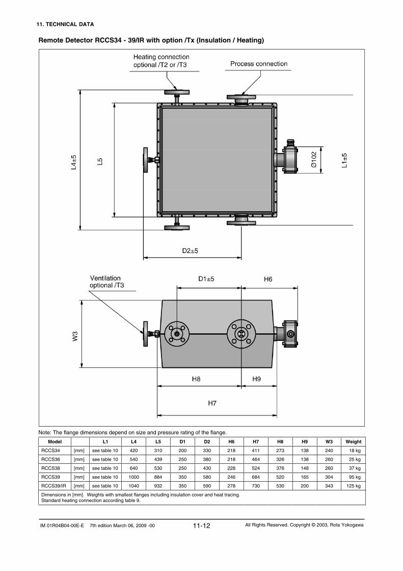
11. TECHNICAL DATA
11-12IM 01R04B04-00E-E 7th edition March 06, 2009 -00 All Rights Reserved. Copyright © 2003, Rota Yokogawa
Remote Detector RCCS34 - 39/IR with option /Tx (Insulation / Heating)
Note: The flange dimensions depend on size and pressure rating of the flange.
Model L1 L4 L5 D1 D2 H6 H7 H8 H9 W3 Weight
RCCS34 [mm] see table 10 420 310 200 330 218 411 273 138 240 18 kg
RCCS36 [mm] see table 10 540 439 250 380 218 464 326 138 260 25 kg
RCCS38 [mm] see table 10 640 530 250 430 228 524 376 148 260 37 kg
RCCS39 [mm] see table 10 1000 884 350 580 246 684 520 165 304 95 kg
RCCS39/IR [mm] see table 10 1040 932 350 590 278 730 530 200 343 125 kg
Dimensions in [mm]. Weights with smallest flanges including insulation cover and heat tracing.Standard heating connection according table 9.

11. TECHNICAL DATA
11-13 IM 01R04B04-00E-E 7th edition March 06, 2009 -00All Rights Reserved. Copyright © 2003, Rota Yokogawa
11.3 Model-, Suffix- and Option-codesIntegral type RCCT3, Modell- and Suffix- Code :Model Suffix Code Description Restrictions
RCCT34RCCT36RCCT38RCCT39RCCT39/IRRCCT39/XR
Nominal Value : 2.7 t/h = 45 kg/minNominal Value : 10 t/h = 170 kg/minNominal Value : 32 t/h = 533 kg/minNominal Value : 100 t/h = 1670 kg/minNominal Value : 250 t/h = 4170 kg/minNominal Value : 500 t/h = 8340 kg/min only with /HP
Power supply -A-D
90 - 264 V AC24 V DC
Indicator direction H1H2V0N0
Detector installation horizontal, tubes downDetector installation horizontal, tubes upDetector installation verticalWithout indicator
recom. for liquid servicerecom. for gas service /GA
Cable conduit connection MA
M20 x 1, female thread with cable glandsANSI ½´´ NPT, female thread without cable glands mandatory with /FF1, /FF3
Process connection size 1) 2301020405060810121520
¾´´DN 15, ½´´DN 25, 1´´DN 40, 1½´´DN 50, 2´´DN 65, 2½´´DN 80, 3´´DN 100, 4´´DN 125, 5´´DN 150, 6´´DN 200, 8´´
see table 10see table 10see table 10see table 10see table 10see table 10see table 10see table 10see table 10see table 10see table1
Process connection rating and style 1) A1A2A3A4A5D2D4D5D6J1J2S2S4S8G9T9
ASME flange class 150, process connection dim. + facing acc. ASME B16.5ASME flange class 300, process connection dim. + facing acc. ASME B16.5ASME flange class 600, process connection dim. + facing acc. ASME B16.5ASME flange class 900, process connection dim. + facing acc. ASME B16.5ASME flange class 1500, process connection dim. + facing acc. ASME B16.5EN flange PN 16, process connection dim. + facing acc. EN 1092-1 Form B2EN flange PN 40, process connection dim. + facing acc. EN 1092-1 Form B2EN flange PN 63, process connection dim. + facing acc. EN 1092-1 Form B2EN flange PN 100, process connection dim. + facing acc. EN 1092-1 Form B2JIS flange 10K, JIS B 2220JIS flange 20K, JIS B 2220Thread acc. DIN 11851Clamp, process connection dimensions acc. DIN 32676Clamp, process connection dim. acc. Tri-Clover (Tri-Clamp) and ½´´ Mini ClampG, female threadNPT, female thread
see table 10see table 10see table 10see table 10see table 10see table 10see table 10see table 10see table 10see table 10see table 10see table 10see table 10see table 10see table 10see table 10
Material of wetted parts 1) SLHC
Stainless steel 316L (1.4404)Hastelloy C-22 (2.4602) only RCCT34 to 39/IR
1) see selection table „Process connection and materials“ (table 10)
Integral type RCCT3, Option- Code :Options Option
codeDescription Restrictions
Hazardous Area Approvals /KF1/KF2/KF3/KF4/FF1
/FF3
/EF1/EF2/EF3/EF4/UF1/UF2/UF3/UF4
ATEX Flame proof converter + Intrinsic safe detectorATEX Flame proof converter + Intrinsic safe detector + Intrinsic safe outputs 1) ATEX Flame proof converter + Intrinsic safe detectorATEX Flame proof converter + Intrinsic safe detector + Intrinsic safe output 1)
FM approval for USA+Canada, Flame proof converter + Intrinsic safe detector
FM approval for USA+Canada, Flame proof converter + Intrinsic safe detector
IECEx Flame proof converter + Intrinsic safe detectorIECEx Flame proof converter + Intrinsic safe detector + Intrinsic safe outputs 1) IECEx Flame proof converter + Intrinsic safe detectorIECEx Flame proof converter + Intrinsic safe detector + Intrinsic safe output 1)
INMETRO Flame proof converter + Intrinsic safe detectorINMETRO Flame proof converter + Intrinsic safe detector + Intrinsic safe outputs 1) INMETRO Flame proof converter + Intrinsic safe detectorINMETRO Flame proof converter + Intrinsic safe detector + Intrinsic safe output 1)
not with /FB, with /HP for gas group IIBnot with /FB, with /HP for gas group IIBonly with /FB, with /HP for gas group IIBonly with /FB, with /HP for gas group IIBonly with cable conduit ´A´; not with /FB, with /HP not for groups A and Bonly with cable conduit ´A´; only with /FB, with /HP not for groups A and Bnot with /FB, with /HP for gas group IIBnot with /FB, with /HP for gas group IIBonly with /FB, with /HP for gas group IIBonly with /FB, with /HP for gas group IIBnot with /FB, with /HP for gas group IIBnot with /FB, with /HP for gas group IIBonly with /FB, with /HP for gas group IIBonly with /FB, with /HP for gas group IIB
1) This is a flame proof device, not an intrinsic safe device!

11. TECHNICAL DATA
11-14IM 01R04B04-00E-E 7th edition March 06, 2009 -00 All Rights Reserved. Copyright © 2003, Rota Yokogawa
Integral type RCCT3, Option- Code (continued) :Options Option
codeDescription Restrictions
High Driving Power /HP High Driving Power not for RCCT34, recommended for RCCT36 to 39, strongly recommended for RCCT39/IR, mandatory for RCCT39/XR
Fieldbus Communication /FB/LC1/EE/BT3
Digital communication (Foundation Fieldbus protocol refer to GS 01R04B05-00E)Provides a PID control function blockProvides software download capabilityWith customer specified tag number of FF- communication + node address in converter
not with /K6only with /FBonly with /FBonly with /FB; max. 32 digits software tag + node address
Active Pulse Output /AP One active pulse output not with /FB; not with /KF2; not with /NM
NAMUR Switch /NM One pulse output acc. to EN 60947-5-6 (NAMUR) not with /FB; not with /AP
Analog Alarm Levels /NA Analog output alarm levels 2.4 mA or 21.6 mA (Standard is acc. to NAMUR rec. 43)
not with /FB
Tag Number /BG With customer specified tag number on name plate max. 16 digits
HART Tag Number (Software Tag) /BT1 With customer specified tag number for HART communication in converter 8 digits for tag, 22 digits for long tag; not with /FB
Flange Facing /DN /RJ
Flange with safety grooves acc. to EN 1092-1 form DRing Type Joint Flanges
only for D2 to D6; not HConly for A3, A4, A5; not HC
Gas Measurement /GA Gas measurement, special factory adjustments and settings to be conform with ANSI/ISA-12.27.01 select /RD
Special Calibration /K2 2)
/K4 /K5 2)
/K6
Custom 5 pts mass-/volume-flow calibration using water with factory certificate (traceable to German national standards)Density adjustment + thermal treatment; (accuracy: 0.001 g/cm³) Custom 10 pts mass-/volume-flow calibration using water with DKD certificate (according EN-17025:2005)Density calibration with 3 different fluids incl. individual temperature compensation with certificate (accuracy: 0.0005 g/cm³)
only RCCT34 to 39; not with /GAnot with /FB
only RCCT34 to 39; not with /GA ; not with /FB; not with sanitary options
Certificates /P2/P3/P6/P8/H1
Certificate of compliance with the order acc. to EN 1024:2004 -2.1As /P2 + Test report acc. to EN 1024: 2004 -2.2 (QIC)Material certificate acc. to EN 1024: 2004 -3.1Pressure test report measuring systemOil and fat free for wetted surface acc. to ASTM G93-03 level C
GOST Approval /QR1/QR2
Russian GOST approvalKazakh GOST approval
not for RCCT39/XR; not with /HP not for RCCT39/XR; not with /HP
Sanitary Type /SF1
/SF2/SA/SE
Surface roughness Ra = 0.8 µm
As /SF1 + Test report roughness of wetted partsAs /SF2 + 3A- declaration of conformity and 3A- markAs /SF2 + EHEDG certificate
not RCCT39/XR; only process connections S2, S4, S8; see also restrictions in table 10
not with process connection S2not with process connection S2
Customer Presetting /PS Presetting sheet with customer data has to be issued with the order
Housing Pressure Test /J1 Rupture pressure proof test and certificate:60 bar (RCCT34, RCCT36), 40 bar (RCCT38), 10 bar (RCCT39, RCCT39/IR)
not for RCCT39/XR
X-Ray Examination /RT X-ray examination of flange welding only material SL
PMI Examination /PM6 PAMI test (6 test points: process connection inlet + outlet, measuring tubes, flow divider inlet + outlet) 3)
Dye Penetration Test /PT Dye penetration test of flange welding
Epoxy Coating /X1 Epoxy coating of converter housing
Dual Seal Approval /DS
/RD
Dual Seal approval (conform with ANSI/ISA-12.27.01)
Rupture disk
only with /FF1; not with process connection A5; not with /FBnot wit RCCT39/XR, preferable with /GA, manda-tory if /DS+/GA is selected
Concentration Measurement 4) /CST/Cxx
Standard concentration measurementAdvanced concentration measurement, details see table „Advanced Concentration Measurement Options“
not with /FB
Instruction Manuals /IEn/IDn /IFn
Quantity of instruction manuals in EnglishQuantity of instruction manuals in GermanQuantity of instruction manuals in French
n = 1 to 3 selectable 5)
n = 1 to 3 selectable 5)
n = 1 to 3 selectable 5)
Quick Delivery /QD Delivery within 24 hours from factory not RCCT39/IR, RCCT39/XR,not with process connection size 23, 12,only with process connection rating A1, A2, D4,only material SL,only for options /KF1, /FF1, /EF1, /UF1, /AP, /NM, /NA, /BG, /P2, /P3, /P8, /CST, /Cxx, /IEn, /IDN , /IFn
Special order /Z Special design must be specification an extra sheet2) Calibration order sheet must be delivered with the order. This is available on the Flow Center Page at Coriolis/RCCx3/Technical Information.3) Measuring tube PAMI test is performed per delivery batch.4) For detailed information please see TI 01R04B04-04E-E. Concentration measurement is recommended with option /K6.5) If no instruction manual is selected, only a CD with instruction manuals is shipped with the instrument. More than 3 manuals of one language on request.
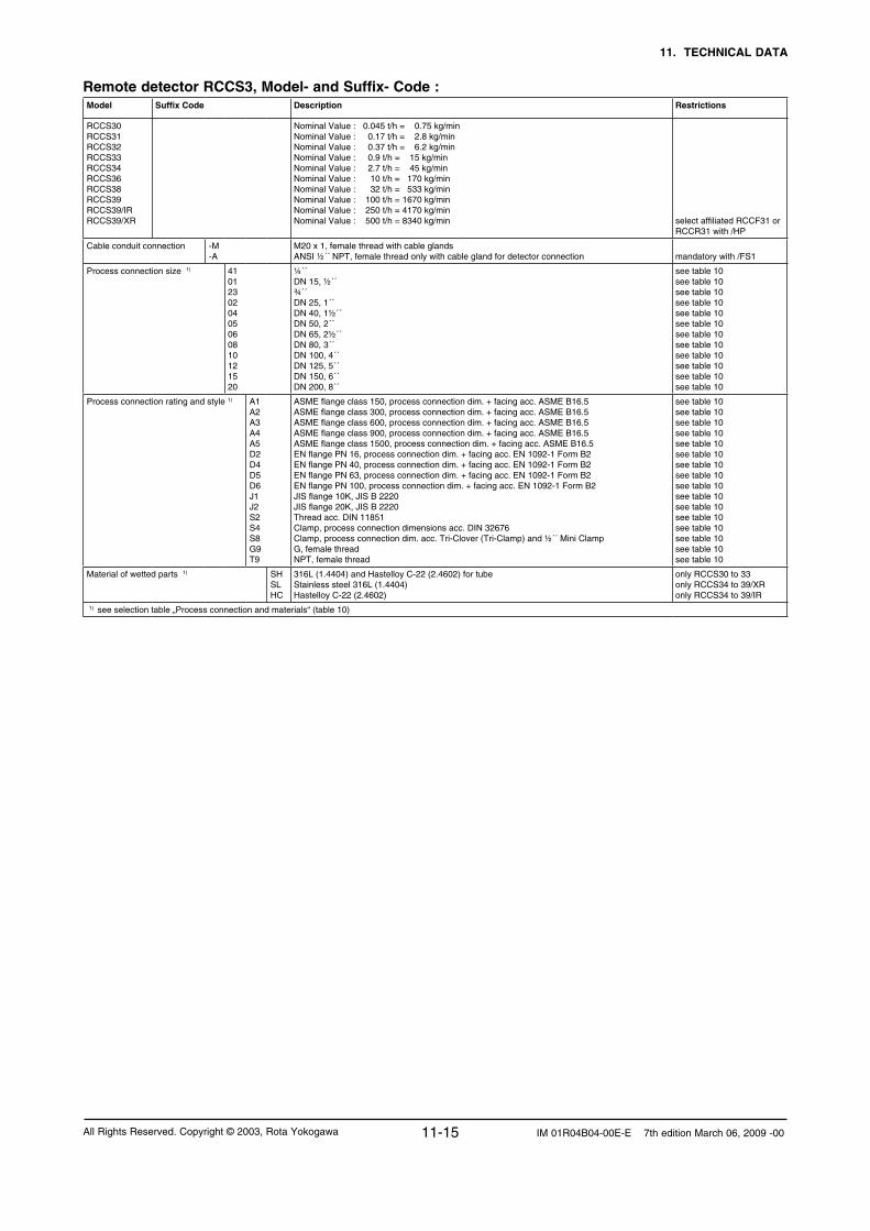
11. TECHNICAL DATA
11-15 IM 01R04B04-00E-E 7th edition March 06, 2009 -00All Rights Reserved. Copyright © 2003, Rota Yokogawa
Remote detector RCCS3, Model- and Suffix- Code :Model Suffix Code Description Restrictions
RCCS30RCCS31RCCS32RCCS33RCCS34RCCS36RCCS38RCCS39RCCS39/IRRCCS39/XR
Nominal Value : 0.045 t/h = 0.75 kg/minNominal Value : 0.17 t/h = 2.8 kg/minNominal Value : 0.37 t/h = 6.2 kg/minNominal Value : 0.9 t/h = 15 kg/minNominal Value : 2.7 t/h = 45 kg/minNominal Value : 10 t/h = 170 kg/minNominal Value : 32 t/h = 533 kg/minNominal Value : 100 t/h = 1670 kg/minNominal Value : 250 t/h = 4170 kg/minNominal Value : 500 t/h = 8340 kg/min select affiliated RCCF31 or
RCCR31 with /HP
Cable conduit connection -M-A
M20 x 1, female thread with cable glandsANSI ½´´ NPT, female thread only with cable gland for detector connection mandatory with /FS1
Process connection size 1) 410123020405060810121520
¼´´DN 15, ½´´ ¾´´DN 25, 1´´DN 40, 1½´´DN 50, 2´´DN 65, 2½´´DN 80, 3´´DN 100, 4´´DN 125, 5´´DN 150, 6´´DN 200, 8´´
see table 10see table 10see table 10see table 10see table 10see table 10see table 10see table 10see table 10see table 10see table 10see table 10
Process connection rating and style 1) A1A2A3A4A5D2D4D5D6J1J2S2S4S8G9T9
ASME flange class 150, process connection dim. + facing acc. ASME B16.5ASME flange class 300, process connection dim. + facing acc. ASME B16.5ASME flange class 600, process connection dim. + facing acc. ASME B16.5ASME flange class 900, process connection dim. + facing acc. ASME B16.5ASME flange class 1500, process connection dim. + facing acc. ASME B16.5EN flange PN 16, process connection dim. + facing acc. EN 1092-1 Form B2EN flange PN 40, process connection dim. + facing acc. EN 1092-1 Form B2EN flange PN 63, process connection dim. + facing acc. EN 1092-1 Form B2EN flange PN 100, process connection dim. + facing acc. EN 1092-1 Form B2JIS flange 10K, JIS B 2220JIS flange 20K, JIS B 2220Thread acc. DIN 11851Clamp, process connection dimensions acc. DIN 32676Clamp, process connection dim. acc. Tri-Clover (Tri-Clamp) and ½´´ Mini ClampG, female threadNPT, female thread
see table 10see table 10see table 10see table 10see table 10see table 10see table 10see table 10see table 10see table 10see table 10see table 10see table 10see table 10see table 10see table 10
Material of wetted parts 1) SHSLHC
316L (1.4404) and Hastelloy C-22 (2.4602) for tubeStainless steel 316L (1.4404)Hastelloy C-22 (2.4602)
only RCCS30 to 33only RCCS34 to 39/XRonly RCCS34 to 39/IR
1) see selection table „Process connection and materials“ (table 10)

11. TECHNICAL DATA
11-16IM 01R04B04-00E-E 7th edition March 06, 2009 -00 All Rights Reserved. Copyright © 2003, Rota Yokogawa
Remote detector RCCS3, Option- Code :Options Option
codeDescription Restrictions
Hazardous Area Approvals 1) /KS1/FS1/ES1/US1
ATEX intrinsically safe approvalFM approval for USA + CanadaIECEx intrinsically safe approvalINMETRO intrinsically safe approval for Brazil
only with cable conduit ´A´
Tag Number /BG With customer specified tag number on name plate max. 16 digits
Flange Facing /DN /RJ
Flange with safety grooves acc. to EN 1092-1 form DRing Type Joint Flanges
only for D2 to D6; not HConly for A3, A4, A5; not HC
Gas Measurement /GA Gas measurement, special factory adjustments and settings select affiliated RCCF31 or RCCR31 with /GA;to be conform with ANSI/ISA-12.27.01 select /RD
Low temperature version /LT -200°C < Tmedium < 150°C not RCCS30 to 33; not with /KS1, /FS1, /ES1, /US1, /MT, /HT, /T1, T2, /T3, /QR1, /QR2
Extended temperature range /MT -70°C < Tmedium < 230°C not RCCS30 to 33; always with /S2 or /Tx; remote cable RCCY033/034 recommended
High temperature version /HT Tmedium up to 350°C only with /Tx; only RCCS34 to 39/IR;remote cable RCCY033/034 recommended
Special Calibration /K2 2)
/K4 /K5 2)
/K6
Custom 5 pts mass-/volume-flow calibration using water with factory certificate (traceable to German national standards)Density adjustment + thermal treatment; (accuracy: 0.001 g/cm³) Custom 10 pts mass-/volume-flow calibration using water with DKD certificate (according EN-17025:2005)Density calibration with 3 different fluids incl. individual temperature compensation with certificate (accuracy: 0.0005 g/cm³)
only RCCS31 to 39; not with /GAnot RCCS30; combined converter not with /FB
only RCCS32 to 39; not with /GA; not with sani-tary options; combined converter not with /FB; only available if converter is also ordered
Certificates /P2/P3/P6/P8/H1
Certificate of compliance with the order acc. to EN 1024:2004 -2.1As /P2 + Test report acc to EN 1024: 2004 -2.2 (QIC)Material certificate acc to EN 1024: 2004 -3.1Pressure test report measuring systemOil and fat free for wetted surface acc. to ASTM G93-03 level C
GOST Approval 1) /QR1/QR2
Russian GOST approvalKazakh GOST approval
not for RCCS39/XR; not with /LTnot for RCCS39/XR; not with /LT
Sanitary Type /SF1
/SF2/SA/SE
Surface roughness Ra = 0.8 µm
As /SF1 + Test report roughness of wetted partsAs /SF2 + 3A- declaration of conformity and 3A- markAs /SF2 + EHEDG- certificate
only RCCS34 to 39/IR; only process connections S2, S4, S8; see also restrictions in table 10
not with process connection S2not with process connection S2
Mounting set /PD 2 inch pipe mounting set only RCCS30 to 33; not with /Tx; recommended for RCCS30
Housing Pressure Test /J1 Rupture pressure proof test and certificate:60 bar (RCCS34, RCCS36), 40 bar (RCCS38), 10 bar (RCCS39, RCCS39/IR)
not for RCCS30 to 33 + RCCS39/XR
Customer insulation / Heating /S2 Terminal box on extension for high or low process temperature not with /T1 ... /T3
Factory Insulating / Heating /T1/T2/T3
InsulationInsulation + Heat carrier heatingInsulation + Heat carrier heating with ventilation
not for RCCS39/XRnot for RCCS39/XRnot for RCCS39/XR
X-Ray Examination /RT X-ray examination of flange welding not material HC
PMI Examination /PM4
/PM6
PAMI test (4 test points: process connection inlet + outlet, flow divider inlet + outlet) 3)
PAMI test (6 test points: process connection inlet + outlet, measuring tubes, flow divider inlet + outlet) 3)
only RCCS30 to 33
not RCCS30 to 33
Dye Penetration Test /PT Dye penetration test of flange welding
Stainless steel cable gland /BS Cable gland stainless steel
Dual Seal Approval /DS
/RD
Dual Seal approval (conform with ANSI/ISA-12.27.01)
Rupture disk
only RCCS34 to 39/XR; only with /FS1; not with process connection A5only RCCS34 to 39/IR, preferable with /GA, not with /Tx, mandatory if /DS + /GA is selected
Quick Delivery /QD Delivery within 24 hours from factory only RCCS34 to 39not with process connection size 23, 12,only with process connection rating A1, A2, D4,only material SL,only for options /KS1, /FS1, /ES1, /US1, /BG, /P2, /P3, /P8
Special order /Z Special design must be specification an extra sheet1) Select affiliated converter RCCF31/RCCR31 with the same approval type (e.g. ATEX).2) Calibration order sheet must be delivered with the order. This is available on the Flow Center Page at Coriolis/RCCx3/Technical Information.3) Measuring tube PAMI test is performed per delivery batch.

11. TECHNICAL DATA
11-17 IM 01R04B04-00E-E 7th edition March 06, 2009 -00All Rights Reserved. Copyright © 2003, Rota Yokogawa
Remote field-mount converter RCCF31, Model-, Suffix- and Option- Code :Model Suffix Code Option
CodeDescription Restrictions
RCCF31 Remote field-mount converter to be connected to RCCS3;when ordered without detector combination option /NC must be selected
Power supply -A-D
100 - 264 V AC24 V DC
Indicator direction H2N0
With indicatorWithout indicator
Cable conduit connection MA
M20 x 1, female thread with cable glandsANSI ½´´ NPT, female thread, only cable gland for detector connection mandatory with /FF1,/FF3
Hazardous Area Approvals 2) /KF1/KF2/KF3/KF4/FF1
/FF3
/EF1/EF2/EF3/EF4/UF1/UF2/UF3/UF4
ATEX Flame proof converter + Intrinsic safe detectorATEX Flame proof converter + Intrinsic safe detector + Intrinsic safe outputs 1) ATEX Flame proof converter + Intrinsic safe detectorATEX Flame proof converter + Intrinsic safe detector + Intrinsic safe output 1)
FM approval for USA+Canada, Flame proof converter + Intrinsic safe detector
FM approval for USA+Canada, Flame proof converter + Intrinsic safe detector
IECEx Flame proof converter + Intrinsic safe detectorIECEx Flame proof converter + Intrinsic safe detector + Intrinsic safe outputs 1) IECEx Flame proof converter + Intrinsic safe detectorIECEx Flame proof converter + Intrinsic safe detector + Intrinsic safe output 1)
INMETRO Flame proof converter + Intrinsic safe detectorINMETRO Flame proof converter + Intrinsic safe detector + Intrinsic safe outputs 1) INMETRO Flame proof converter + Intrinsic safe detectorINMETRO Flame proof converter + Intrinsic safe detector + Intrinsic safe output 1)
not with /FB, with /HP for gas group IIBnot with /FB, with /HP for gas group IIBonly with /FB, with /HP for gas group IIBonly with /FB, with /HP for gas group IIBonly with cable conduit ´A´; not with /FB, with /HP not for groups A and Bonly with cable conduit ´A´; only with /FB, with /HP not for groups A and Bnot with /FB, with /HP for gas group IIBnot with /FB, with /HP for gas group IIBonly with /FB, with /HP for gas group IIBonly with /FB, with /HP for gas group IIBnot with /FB, with /HP for gas group IIBnot with /FB, with /HP for gas group IIBonly with /FB, with /HP for gas group IIBonly with /FB, with /HP for gas group IIB
High Driving Power /HP High Driving Power not for combination with RCCS30 to 34, recommended for combination with RCCS36 to 39, strongly recommended for combination with RCCS39/IR, mandatory for combination with RCCS39/XR
Fieldbus Communication /FB/LC1/EE/BT3
Digital communication (Foundation Fieldbus protocol refer to GS 01R04B05-00E)Provides a PID control function blockProvides software download capabilityWith customer specified tag number of FF- communication + node address in converter
combined RCCS3 not with /K6
only with /FBonly with /FBonly with /FB; max. 32 digits software tag + node address
Active Pulse Output /AP One active pulse output not with /FB; not with /KF2; not with /NM
NAMUR Switch /NM One pulse output acc. EN 60947-5-6 (NAMUR) not with /FB; not with /AP
Analog Alarm Levels /NA Analog output alarm levels 2.4 mA or 21.6 mA (Standard is acc. NAMUR rec. 43)
not with /FB
Tag Number /BG With customer specified tag number on name plate max. 16 digits
HART Tag Number (Software Tag) /BT1 With customer specified tag number for HART communication in converter 8 digits for tag, 22 digits for long tag; not with /FB
Gas Measurement /GA Gas measurement, special factory adjustments and settings select affiliated RCCS3 with /GA
No Combination /NC No combination with detector
GOST Approval 2) /QR1/QR2
Russian GOST approvalKazakh GOST approval
not with /HPnot with /HP
Customer Presetting /PS Presetting sheet with customer data has to be issued with the order
Epoxy Coating /X1 Epoxy coating of converter housing
Concentration Measurement 3) /CST/Cxx
Standard concentration measurementAdvanced concentration measurement, details see table „Advanced Concentration Measurement Options“
not with /FB
Instruction Manuals /IEn/IDn /IFn
Quantity of instruction manuals in EnglishQuantity of instruction manuals in GermanQuantity of instruction manuals in French
n = 1 to 3 selectable 5)
n = 1 to 3 selectable 5)
n = 1 to 3 selectable 5)
Quick Delivery /QD Delivery within 24 hours from factory not with /KF2, EF2, /UF2, /FB, /GA, /QR1, /QR2, /PS, /X1
Special order /Z Special design must be specification an extra sheet1) This is a flame proof device, not an intrinsic safe device!2) Select affiliated RCCS3 with the same approval type (e.g. /KFx with /KS1).3) For detailed information please see TI 01R04B04-04E-E. Option /K6 of RCCS3 is recommended with concentration measurement. 4) If no instruction manual is selected, only a CD with instruction manuals is shipped with the instrument. More than 3 manuals of one language on request.

11. TECHNICAL DATA
11-18IM 01R04B04-00E-E 7th edition March 06, 2009 -00 All Rights Reserved. Copyright © 2003, Rota Yokogawa
Remote cable RCCY03, Model-, Suffix- and Option- Code :Model Suffix Code Option
CodeDescription Restrictions
RCCY031RCCY032RCCY033RCCY034
Length in ´meter´Length in ´feet´Length in ´meter´Length in ´feet´
max. ambient temperature 70°C; with /FFx or /FS1: 50°Cmax. ambient temperature 70°C; with /FFx or /FS1: 50°Cmax. ambient temperature 105°C; with /FFx or /FS1: 85°Cmax. ambient temperature 105°C; with /FFx or /FS1: 85°C
Cable ends -0-1
No termination, with one termination kitTerminated only RCCY031, RCCY032
Cable length Lxxx Enter the length max. 300m / 999ft (with /FFx or /FS1 max. 50m / 165ft);the following lengths can be ordered (e.g. 3m = L003):RCCY031-1: 3m, 5m, 10m, 15m, 30m, 50mRCCY031-0: 3m, 5m, 10m, 15m, 30m, 50m, 100m, 150m, 200m, 250m, 300mRCCY032-1: 10ft, 15ft, 30ft, 50ft, 100ft, 150ftRCCY032-0: 10ft, 15ft, 30ft, 50ft, 100ft, 150ft, 300ft, 500ft, 1000ftRCCY033-0: 3m, 5m, 10m, 15m, 50m, 100m, 150m, 300mRCCY034-0: 10ft, 30ft, 50ft, 100ft, 150ft, 300ft, 500ft, 1000ft
Options:Hazardous area installation Termination kitsQuick delivery
/KS1/TKxx/QD
Blue cable for Ex-i indicationQuantity of additional termination kitsDelivery within 24 hours from factory
xx = 01 to 99only RCCY031-1, L003, L005, L010
Remote rack-mount converter RCCR31, Model-, Suffix- and Option- Code :Model Suffix Code Option
CodeDescription Restrictions
RCCR31 Remote converter for 19´´ rack mounting to be connected to RCCS3
Power supply -A-D
100 - 264 V AC24 V DC
Hazardous Area Approvals 1) /KS1/FS1/ES1/US1
ATEX associated apparatus for intrinsic safe detector connection for gas group IICFM associated apparatus for intrinsic safe detector connectionIECEx associated apparatus for intrinsic safe detector connection for gas group IICINMETRO associated apparatus for intrinsic safe detector connection for gas group IIC
with /HP for gas group IIBwith /HP not for gas groups A and Bwith /HP for gas group IIBwith /HP for gas group IIB
High Driving Power /HP High Driving Power not for combination with RCCS30 to 34, recom-mended for combination with RCCS36 to 39, strongly recommended for combination with RCCS39/IR, mandatory for combination with RCCS39/XR
Active Pulse Output /AP One active pulse output not with /NM
NAMUR Switch /NM One pulse output acc. EN 60947-5-6 (NAMUR) not with /AP
Analog Alarm Levels /NA Analog output alarm levels 2.4 mA or 21.6 mA (Standard is acc. NAMUR rec. 43)
Tag Number /BG With customer specified tag number on name plate max. 16 digits
HART Tag Number (Software Tag) /BT1 With customer specified tag number for HART communication in converter 8 digits for tag, 22 digits for long tag
Gas Measurement /GA Gas measurement, special factory adjustments and settings select affiliated RCCS3 with /GA
No Combination /NC No combination with detector
Customer Presetting /PS Presetting sheet with customer data has to be issued with the order
Concentration Measurement 2) /CST/Cxx
Standard concentration measurementAdvanced concentration measurement, details see table „Advanced Concentration Measurement Options“
Subrack /SR1/SR2
Subrack for 2 converter RCCR31 with mountingSubrack for 4 converter RCCR31 with mounting
Instruction Manuals /IEn/IDn /IFn
Quantity of instruction manuals in EnglishQuantity of instruction manuals in GermanQuantity of instruction manuals in French
n = 1 to 3 selectable 3)
n = 1 to 3 selectable 3)
n = 1 to 3 selectable 3)
Special order /Z Special design must be specification an extra sheet1) Select affiliated RCCS3 with the same approval type (e.g. /KS1 with /KS1).2) For detailed information please see TI 01R04B04-04E-E. Option /K6 of RCCS3 is recommended with concentration measurement.3) If no instruction manual is selected, only a CD with instruction manuals is shipped with the instrument. More than 3 manuals of one language on request.

11. TECHNICAL DATA
11-19 IM 01R04B04-00E-E 7th edition March 06, 2009 -00All Rights Reserved. Copyright © 2003, Rota Yokogawa
Advanced Concentration Measurement Options (others on request), recommended with option /K6:Option Display Components Concentration
rangeTemp. range Source of concentration- / density table
/C01 °Brix Sugar / Water 0 - 85 °Brix 0 - 80°C PTB- Messages 100 5/90:„The density of watery Saccarose solutions after the introduction of the international
temperature scale of 1990 (ITS1990)“ Table 5
/C02 WT% NaOH / Water 2 - 50 WT% 0 - 100°C D´Ans-Lax, Handbook for chemists and physicists Vol.1, 3rd edition, 1967
/C03 WT% KOH / Water 0 - 60 WT% 54 - 100°C D´Ans-Lax, Handbook for chemists and physicists Vol.1, 3rd edition, 1967
/C04 WT% NH4NO3 / Water 1 - 50 WT% 0 - 80°C Source undefined
/C05 WT% NH4NO3 / Water 20 - 70 WT% 20 - 100°C Source undefined
/C06 1) WT% HCl / Water 22 - 34 WT% 20 - 40°C D´Ans-Lax, Handbook for chemists and physicists Vol.1, 3rd edition, 1967
/C07 WT% HNO3 / Water 50 - 67 WT% 10 - 60°C Source undefined
/C09 WT% H2O2 / Water 30 - 75 WT% 4 - 44°C Source undefined
/C10 WT% Ethylene Glycol / Water 10 - 50 WT% -20 - 40°C Source undefined
/C11 WT% Amylum = starch / Water 33 - 43 WT% 35 - 45°C Source undefined
/C12 WT% Methanol / Water 35 - 60 WT% 0 - 40°C Source undefined
/C20 WT% Alcohol / Water 55 - 100 WT% 10 - 40°C Source undefined
/C21 °Brix Sugar / Water 40 - 80 °Brix 75 - 100°C Source undefined
1) only with material HC

11. TECHNICAL DATA
11-20IM 01R04B04-00E-E 7th edition March 06, 2009 -00 All Rights Reserved. Copyright © 2003, Rota Yokogawa
Table 10 : Selection table process connection and materials, installation length
RCCS30-32
RCCS33
RCCS34RCCT34
RCCS36RCCT36
RCCS38RCCT38
RCCS39RCCT39
RCCS39/IRRCCT39/IR
RCCS39/XRRCCT39/XR
SH SH SL HC SL HC SL HC SL HC SL HC SL HC
Fla
ng
es a
cco
rdin
g t
o A
SM
E B
16.5
01A1 ½“-150 240 240 370 ---- ---- ---- ---- ---- ---- ---- ---- ---- ---- ----01A2 ½“-300 240 240 370 ---- ---- ---- ---- ---- ---- ---- ---- ---- ---- ----01A3 ½“-600 250 250 380 ---- ---- ---- ---- ---- ---- ---- ---- ---- ---- ----01A4 ½“-900 ---- 270 ---- ---- ---- ---- ---- ---- ---- ---- ---- ---- ---- ----01A5 ½“-1500 270 ---- 400 ---- ---- ---- ---- ---- ---- ---- ---- ---- ---- ----02A1 1“-150 240 240 370 390 500 ---- ---- ---- ---- ---- ---- ---- ---- ----02A2 1“-300 240 240 370 390 500 ---- ---- ---- ---- ---- ---- ---- ---- ----02A3 1“-600 260 260 390 ---- 520 ---- ---- ---- ---- ---- ---- ---- ---- ----02A4 1“-900 ---- 320 ---- ---- ---- ---- ---- ---- ---- ---- ---- ---- ---- ----02A5 1“-1500 320 ---- 450 ---- 540 ---- ---- ---- ---- ---- ---- ---- ---- ----04A1 1½“-150 250 250 380 390 500 520 600 ---- ---- ---- ---- ---- ---- ----04A2 1½“-300 250 250 380 390 510 520 600 ---- ---- ---- ---- ---- ---- ----04A3 1½“-600 270 270 400 ---- 530 ---- 620 ---- ---- ---- ---- ---- ---- ----04A4 1½“-900 ---- 340 ---- ---- ---- ---- 640 ---- ---- ---- ---- ---- ---- ----04A5 1½“-1500 340 ---- 470 ---- 600 ---- ---- ---- ---- ---- ---- ---- ---- ----05A1 2“-150 ---- ---- ---- ---- 510 520 600 620 ---- ---- ---- ---- ---- ----05A2 2“-300 ---- ---- ---- ---- 510 520 600 620 ---- ---- ---- ---- ---- ----05A3 2“-600 ---- ---- ---- ---- 540 ---- 630 ---- ---- ---- ---- ---- ---- ----05A4 2“-900 ---- ---- ---- ---- ---- ---- 720 ---- ---- ---- ---- ---- ---- ----05A5 2“-1500 ---- ---- ---- ---- 660 ---- ---- ---- ---- ---- ---- ---- ---- ----06A1 2½“-150 ---- ---- ---- ---- ---- ---- 610 620 ---- ---- ---- ---- ---- ----06A2 2½“-300 ---- ---- ---- ---- ---- ---- 610 620 ---- ---- ---- ---- ---- ----06A3 2½“-600 ---- ---- ---- ---- ---- ---- 640 ---- ---- ---- ---- ---- ---- ----06A4 2½“-900 ---- ---- ---- ---- ---- ---- 760 ---- ---- ---- ---- ---- ---- ----08A1 3“-150 ---- ---- ---- ---- ---- ---- 610 620 1000 1020 ---- ---- ---- ----08A2 3“-300 ---- ---- ---- ---- ---- ---- 620 620 1000 1020 ---- ---- ---- ----08A3 3“-600 ---- ---- ---- ---- ---- ---- 640 ---- 1000 ---- ---- ---- ---- ----08A4 3“-900 ---- ---- ---- ---- ---- ---- 760 ---- ---- ---- ---- ---- ---- ----10A1 4“-150 ---- ---- ---- ---- ---- ---- ---- ---- 1000 1020 1100 ---- ---- ----10A2 4“-300 ---- ---- ---- ---- ---- ---- ---- ---- 1000 1020 1100 ---- ---- ----10A3 4“-600 ---- ---- ---- ---- ---- ---- ---- ---- 1030 ---- 1100 ---- ---- ----12A1 5“-150 ---- ---- ---- ---- ---- ---- ---- ---- 1000 1020 1100 1100 ---- ----12A2 5“-300 ---- ---- ---- ---- ---- ---- ---- ---- 1000 1020 1100 1100 ---- ----12A3 5“-600 ---- ---- ---- ---- ---- ---- ---- ---- 1040 ---- 1160 ---- ---- ----15A1 6“-150 ---- ---- ---- ---- ---- ---- ---- ---- ---- ---- 1100 1100 1350 ----15A2 6“-300 ---- ---- ---- ---- ---- ---- ---- ---- ---- ---- 1100 1100 1350 ----15A3 6“-600 ---- ---- ---- ---- ---- ---- ---- ---- ---- ---- 1200 ---- ---- ----20A1 8“-150 ---- ---- ---- ---- ---- ---- ---- ---- ---- ---- ---- ---- 1350 ----20A2 8“-300 ---- ---- ---- ---- ---- ---- ---- ---- ---- ---- ---- ---- 1350 ----
Fla
ng
es a
cco
rdin
g t
o E
N 1
092-
1
01D4 DN 15 PN 40 240 240 370 ---- ---- ---- ---- ---- ---- ---- ---- ---- ---- ----01D6 DN 15 PN 100 250 250 380 ---- ---- ---- ---- ---- ---- ---- ---- ---- ---- ----02D4 DN 25 PN 40 240 240 370 390 500 520 ---- ---- ---- ---- ---- ---- ---- ----02D6 DN 25 PN 100 260 260 390 ---- 520 ---- ---- ---- ---- ---- ---- ---- ---- ----04D4 DN 40 PN 40 240 240 370 390 500 520 600 ---- ---- ---- ---- ---- ---- ----04D6 DN 40 PN 100 320 320 450 ---- 560 ---- 620 ---- ---- ---- ---- ---- ---- ----05D4 DN 50 PN 40 ---- ---- ---- ---- 500 520 600 620 ---- ---- ---- ---- ---- ----05D5 DN 50 PN 63 ---- ---- ---- ---- 520 ---- 620 ---- ---- ---- ---- ---- ---- ----05D6 DN 50 PN 100 ---- ---- ---- ---- 590 ---- 660 ---- ---- ---- ---- ---- ---- ----08D4 DN 80 PN 40 ---- ---- ---- ---- ---- ---- 610 620 1000 1020 ---- ---- ---- ----08D5 DN 80 PN 63 ---- ---- ---- ---- ---- ---- 620 ---- 1000 ---- ---- ---- ---- ----08D6 DN 80 PN 100 ---- ---- ---- ---- ---- ---- 730 ---- 1000 ---- ---- ---- ---- ----10D2 DN 100 PN 16 ---- ---- ---- ---- ---- ---- ---- ---- ---- ---- 1100 ---- ---- ----10D4 DN 100 PN 40 ---- ---- ---- ---- ---- ---- ---- ---- 1000 1020 1100 ---- ---- ----10D5 DN 100 PN 63 ---- ---- ---- ---- ---- ---- ---- ---- 1000 ---- 1100 ---- ---- ----10D6 DN 100 PN 100 ---- ---- ---- ---- ---- ---- ---- ---- 1050 ---- 1100 ---- ---- ----12D2 DN 125 PN 16 ---- ---- ---- ---- ---- ---- ---- ---- ---- ---- 1100 1100 ---- ----12D4 DN 125 PN 40 ---- ---- ---- ---- ---- ---- ---- ---- 1000 1020 1100 1100 ---- ----12D5 DN 125 PN 63 ---- ---- ---- ---- ---- ---- ---- ---- 1000 ---- 1100 ---- ---- ----12D6 DN 125 PN 100 ---- ---- ---- ---- ---- ---- ---- ---- 1100 ---- 1140 ---- ---- ----15D2 DN 150 PN 16 ---- ---- ---- ---- ---- ---- ---- ---- ---- ---- 1100 1100 1350 ----15D4 DN 150 PN 40 ---- ---- ---- ---- ---- ---- ---- ---- ---- ---- 1100 1100 1350 ----15D5 DN 150 PN 63 ---- ---- ---- ---- ---- ---- ---- ---- ---- ---- 1140 ---- ---- ----15D6 DN 150 PN 100 ---- ---- ---- ---- ---- ---- ---- ---- ---- ---- 1180 ---- ---- ----20D2 DN 200 PN 16 ---- ---- ---- ---- ---- ---- ---- ---- ---- ---- ---- ---- 1350 ----20D4 DN 200 PN 40 ---- ---- ---- ---- ---- ---- ---- ---- ---- ---- ---- ---- 1350 ----

11. TECHNICAL DATA
11-21 IM 01R04B04-00E-E 7th edition March 06, 2009 -00All Rights Reserved. Copyright © 2003, Rota Yokogawa
Table 10 : Selection table process connection and materials, installation length (continued)
RCCS30-32
RCCS33
RCCS34RCCT34
RCCS36RCCT36
RCCS38RCCT38
RCCS39RCCT39
RCCS39/IRRCCT39/IR
RCCS39/XRRCCT39/XR
SH SH SL HC SL HC SL HC SL HC SL HC SL HC
Fla
ng
es a
cco
rdin
g t
o J
IS B
222
0
01J1 DN 15 10K 240 240 370 ---- ---- ---- ---- ---- ---- ---- ---- ---- ---- ----01J2 DN 15 20K 240 240 370 ---- ---- ---- ---- ---- ---- ---- ---- ---- ---- ----02J1 DN 25 10K 240 240 370 ---- 500 ---- ---- ---- ---- ---- ---- ---- ---- ----02J2 DN 25 20K 240 240 370 ---- 500 ---- ---- ---- ---- ---- ---- ---- ---- ----04J1 DN 40 10K 240 240 370 ---- 500 ---- 600 ---- ---- ---- ---- ---- ---- ----04J2 DN 40 20K 240 240 370 ---- 500 ---- 600 ---- ---- ---- ---- ---- ---- ----05J1 DN 50 10K ---- ---- ---- ---- 500 ---- 600 ---- ---- ---- ---- ---- ---- ----05J2 DN 50 20K ---- ---- ---- ---- 500 ---- 600 ---- ---- ---- ---- ---- ---- ----08J1 DN 80 10K ---- ---- ---- ---- ---- ---- 600 ---- 1000 ---- ---- ---- ---- ----08J2 DN 80 20K ---- ---- ---- ---- ---- ---- 600 ---- 1000 ---- ---- ---- ---- ----10J1 DN 100 10K ---- ---- ---- ---- ---- ---- ---- ---- 1000 ---- 1100 ---- ---- ----10J2 DN 100 20K ---- ---- ---- ---- ---- ---- ---- ---- 1000 ---- 1100 ---- ---- ----
12J1 DN 125 10K ---- ---- ---- ---- ---- ---- ---- ---- 1000 ---- 1100 ---- ---- ----
12J2 DN 125 20K ---- ---- ---- ---- ---- ---- ---- ---- 1000 ---- 1100 ---- ---- ----15J1 DN 150 10K ---- ---- ---- ---- ---- ---- ---- ---- ---- ---- 1100 ---- ---- ----15J2 DN 150 20K ---- ---- ---- ---- ---- ---- ---- ---- ---- ---- 1100 ---- ---- ----
Cla
mp
DIN
01S4 DN 15 240 240 ---- ---- ---- ---- ---- ---- ---- ---- ---- ---- ---- ----02S4 DN 25 240 240 370 *) ---- ---- ---- ---- ---- ---- ---- ---- ---- ---- ----04S4 DN 40 240 240 370 ---- 500 *) ---- ---- ---- ---- ---- ---- ---- ---- ----05S4 DN 50 ---- ---- ---- ---- 500 ---- 600 *) ---- ---- ---- ---- ---- ---- ----06S4 DN 65 ---- ---- ---- ---- ---- ---- 600 ---- ---- ---- ---- ---- ---- ----10S4 DN 100 ---- ---- ---- ---- ---- ---- ---- ---- 1000 ---- ---- ---- ---- ----
Tri
-Cla
mp
01S8 ½“ 240 240 ---- ---- ---- ---- ---- ---- ---- ---- ---- ---- ---- ----02S8 1“ 240 240 370 *) ---- ---- ---- ---- ---- ---- ---- ---- ---- ---- ----04S8 1½“ 240 240 370 ---- 500 *) ---- ---- ---- ---- ---- ---- ---- ---- ----05S8 2“ ---- ---- ---- ---- 500 ---- 600 *) ---- ---- ---- ---- ---- ---- ----08S8 3“ ---- ---- ---- ---- ---- ---- 600 ---- ---- ---- ---- ---- ---- ----10S8 4“ ---- ---- ---- ---- ---- ---- ---- ---- 1000 ---- ---- ---- ---- ----
DIN
1185
1 02S2 DN 25 240 240 370 ---- ---- ---- ---- ---- ---- ---- ---- ---- ---- ----04S2 DN 40 ---- ---- ---- ---- 500 ---- ---- ---- ---- ---- ---- ---- ---- ----05S2 DN 50 ---- ---- ---- ---- ---- ---- 600 ---- ---- ---- ---- ---- ---- ----10S2 DN 100 ---- ---- ---- ---- ---- ---- ---- ---- 1000 ---- ---- ---- ---- ----41G9 G¼“ female 260 260 ---- ---- ---- ---- ---- ---- ---- ---- ---- ---- ---- ----01G9 G½“ female 260 260 390 ---- ---- ---- ---- ---- ---- ---- ---- ---- ---- ----23G9 G¾“ female 260 260 390 ---- ---- ---- ---- ---- ---- ---- ---- ---- ---- ----41T9 NPT¼“ female 260 260 ---- ---- ---- ---- ---- ---- ---- ---- ---- ---- ---- ----01T9 NPT½“ female 260 260 390 ---- ---- ---- ---- ---- ---- ---- ---- ---- ---- ----23T9 NPT¾“ female 260 260 390 ---- ---- ---- ---- ---- ---- ---- ---- ---- ---- ----
*) not possible with Option SFx, SA, SE

IM 01R04B04-00E-E 7th edition March 06, 2009 -00 All Rights Reserved. Copyright © 2003, Rota Yokogawa
Yokogawa has an extensive sales and distribution network. Please refer to the European website (www.yokogawa.com/eu) to contact your nearest representative.
Euroweg 23825 HD AMERSFOORTThe Netherlandswww.yokogawa.com/eu
YOKOGAWA ELECTRIC CORPORATIONWorld Headquarters9-32, Nakacho 2-chome, Musashino-shiTokyo 180-8750Japanwww.yokogawa.com
YOKOGAWA CORPORATION OF AMERICA2 Dart RoadNewnan GA 30265USAwww.yokogawa.com/us
YOKOGAWA ELECTRIC ASIA Pte. LTD.5 Bedok South RoadSingapore 469270Singaporewww.yokogawa.com/sg
YOKOGAWA CHINA CO. LTD.3F Tower D Cartelo Crocodile BuildingNo.568 West Tianshan Road Changing DistrictShanghai, Chinawww.yokogawa.com/cn
YOKOGAWA MIDDLE EAST B.S.C.(c)P.O. Box 10070, ManamaBuilding 577, Road 2516, Busaiteen 225Muharraq, Bahrainwww.yokogawa.com/bh
Subject to change without notice