ROTAMASS 3 Series Coriolis Mass Flow and Density Meter ... · A Coriolis mass flowmeter measures...
4
ROTAMASS 3 Series Coriolis Mass Flow and Density Meter Yokogawa Technical Report English Edition Vol.53 No.2 (2010) ROTAMASS 3 Series Coriolis Mass Flow and Density Meter - Achieving High-speed Measurement with High Accuracy and Robustness - Shuuji Urabe *1 Kiyoaki Koyama *1 The Yokogawa Group has developed the ROTAMASS 3 series Coriolis flow and density meters. A Coriolis flowmeter can directly measure mass flow of fluid regardless of its temperature and pressure. The ROTAMASS 3 series meters have such unique features as fast signal processing, anti-vibration mechanism, and high accuracy density measurement. This paper describes these features and applications of the ROTAMASS 3 series. INTRODUCTION T he Coriolis flowmeter has many features such as direct measurement of mass flow and measurement of fluid density, which other flowmeters do not support. Therefore, since being introduced for practical use in the late 1970s, its market has rapidly expanded in many industries such as oil, chemicals, and foods. The YOKOGAWA Group has also been focusing interest on its features and continued R&D in this area. Eventually, following joint R&D with ROTA YOKOGAWA GmbH & Co. KG (Germany), Yokogawa released the ROTAMASS series Coriolis flowmeters in 1993 worldwide, mainly for the Europe, North America, and Southeast Asia markets. Process flowmeters must be able to measure flow rates at high speed and accuracy, and must also be robust to withstand stresses and vibrations applied through the process connection with the piping. To achieve these properties, we developed a high speed high accuracy digital signal processing algorithm and a Box-in-Box structure to reduce the impact from external force and vibration. This paper describes the features of the signal processing and structure, and application examples of the ROTAMASS series Coriolis mass flow and density meters. MEASUREMENT PRINCIPLE AND FEATURES OF THE CORIOLIS FLOWMETER A Coriolis mass flowmeter measures the mass flow of fluid based on the interaction of Coriolis forces generated between the flowing fluid and vibrating measurement tube. The principle is outlined in Figure 1. The U-shape tube is repeatedly swung around the fixed end as a pivot like a cantilever. When fluid flows in this tube, Coriolis forces (Fc) are generated at both the inlet and outlet sides of the tube according to the ascent and descent of the tube. Since the directions of forces generated at inlet and outlet sides are opposite, torque is created generating torsion angle of the tube. Because the Coriolis force Fc is proportional to the mass flow of the fluid, the mass flow can be measured by detecting the torsion angle. Figure 1 Measurement Principle of the Coriolis Flowmeter (1) Figure 2 shows the flowmeter with the major elements necessary for measurements and signals. A pair of a magnet and driver coil is mounted at the apex of the U-shaped tube, and two pairs of a magnet and sensor coil are arranged at the upstream and downstream sides respectively. The positive feedback of electromagnetically induced output of the sensor coil to the driver coil leads to self-oscillation of the measurement tube at its resonant frequency. The torsion angle of the tube can be calculated based on the phase difference between the output signals of the two sensor coils. That is, the mass flow rate can be derived from the phase difference of the two signals. It is possible to calculate simultaneously the mass of the fluid based on the signal frequency, from which the density can be derived. Fc Fc Torsion angle Fluid U-shaped tube Vibration U-shaped tube Fixed end Fixed end Fc ∝ mass flow *1 Field Instruments Business Center, Industrial Automation Business Headquarters 23 85 MASS
Transcript of ROTAMASS 3 Series Coriolis Mass Flow and Density Meter ... · A Coriolis mass flowmeter measures...
ROTAMASS 3 Series Coriolis Mass Flow and Density Meter
Yokogawa Technical Report English Edition Vol.53 No.2 (2010)
ROTAMASS 3 Series Coriolis Mass Flow and Density Meter- Achieving High-speed Measurement with High Accuracy and Robustness -
Shuuji Urabe *1 Kiyoaki Koyama *1
The Yokogawa Group has developed the ROTAMASS 3 series Coriolis flow and density meters. A Coriolis flowmeter can directly measure mass flow of fluid regardless of its temperature and pressure. The ROTAMASS 3 series meters have such unique features as fast signal processing, anti-vibration mechanism, and high accuracy density measurement. This paper describes these features and applications of the ROTAMASS 3 series.
INTRODUCTION
The Coriolis flowmeter has many features such as direct measurement of mass f low and measurement of f luid
density, which other f lowmeters do not support. Therefore, since being introduced for practical use in the late 1970s, its market has rapidly expanded in many industries such as oil, chemicals, and foods. The YOKOGAWA Group has also been focusing interest on its features and continued R&D in this area. Eventually, following joint R&D with ROTA YOKOGAWA GmbH & Co. KG (Germany), Yokogawa released the ROTAMASS series Coriolis f lowmeters in 1993 worldwide, mainly for the Europe, North America, and Southeast Asia markets.
Process flowmeters must be able to measure flow rates at high speed and accuracy, and must also be robust to withstand stresses and vibrations applied through the process connection with the piping. To achieve these properties, we developed a high speed high accuracy digital signal processing algorithm and a Box-in-Box structure to reduce the impact from external force and vibration. This paper describes the features of the signal processing and structure, and application examples of the ROTAMASS series Coriolis mass flow and density meters.
MEASUREMENT PRINCIPLE AND FEATURES OF THE CORIOLIS FLOWMETER
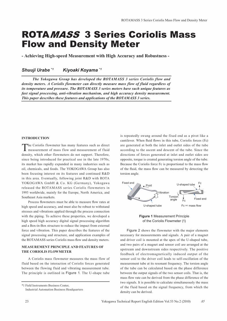
A Coriolis mass f lowmeter measures the mass f low of f luid based on the interaction of Coriolis forces generated between the flowing fluid and vibrating measurement tube. The principle is outlined in Figure 1. The U-shape tube
is repeatedly swung around the fixed end as a pivot like a cantilever. When fluid flows in this tube, Coriolis forces (Fc) are generated at both the inlet and outlet sides of the tube according to the ascent and descent of the tube. Since the directions of forces generated at inlet and outlet sides are opposite, torque is created generating torsion angle of the tube. Because the Coriolis force Fc is proportional to the mass flow of the fluid, the mass flow can be measured by detecting the torsion angle.
Figure 1 Measurement Principle of the Coriolis Flowmeter (1)
Figure 2 shows the flowmeter with the major elements necessary for measurements and signals. A pair of a magnet and driver coil is mounted at the apex of the U-shaped tube, and two pairs of a magnet and sensor coil are arranged at the upstream and downstream sides respectively. The positive feedback of electromagnetically induced output of the sensor coil to the driver coil leads to self-oscillation of the measurement tube at its resonant frequency. The torsion angle of the tube can be calculated based on the phase difference between the output signals of the two sensor coils. That is, the mass flow rate can be derived from the phase difference of the two signals. It is possible to calculate simultaneously the mass of the f luid based on the signal frequency, from which the density can be derived.
Fc
Fc
Torsionangle
Fluid
U-shaped tube
Vibration
U-shaped tubeFixed end
Fixed end
Fc ∝ mass flow
*1 Field Instruments Business Center, Industrial Automation Business Headquarters
23 85
MASS
ROTAMASS 3 Series Coriolis Mass Flow and Density Meter
Yokogawa Technical Report English Edition Vol.53 No.2 (2010)
Figure 2 Measurement Principle of the Coriolis Flowmeter (2)
A Coriolis mass flowmeter:
1) can directly measure the mass f low rate based on the principle of measurement,
2) can measure the mass flow rate with high accuracy of ±0.1%,3) has a wide measurement flow rate range,4) can measure the density of f luid based on the oscillating
frequency,5) is not affected by viscosity and density of the fluid, and does
not require straight pipe sections upstream nor downstream of the flowmeter, and
6) can measure non-conductive fluids.
In general, chemical reactions, etc. are described in moles or masses of substances. Therefore, it is very useful to be able to directly measure the mass flow rate in chemical and pharmaceutical industry applications. Other flowmeters such as differential pressure, electromagnetic, and vortex f lowmeters must convert from volume f low rate to mass flow rate while compensating for temperature and pressure. Although magnetic f lowmeters can measure only electro-conductive fluids due to the principle of measurement, Coriolis mass f lowmeters can measure non-conductive f luids. This is one reason why they are widely used in the chemical and pharmaceutical industries
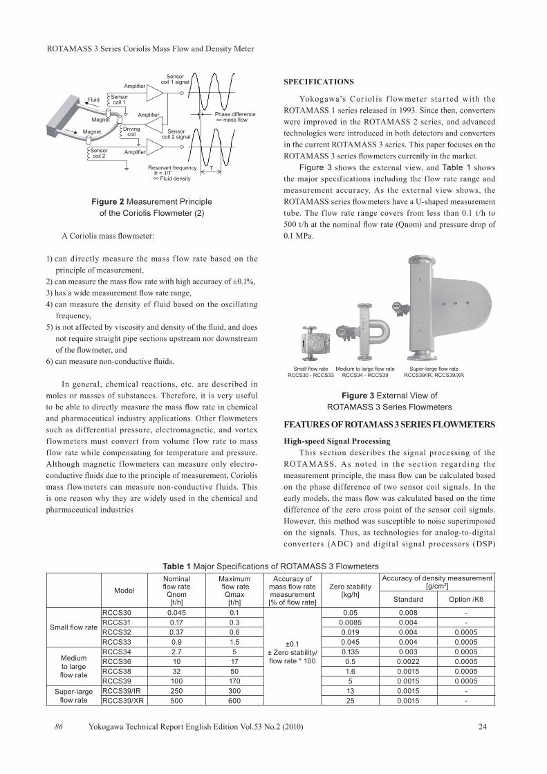
SPECIFICATIONS
Yokogawa’s Cor iol is f lowmeter sta r ted with the ROTAMASS 1 series released in 1993. Since then, converters were improved in the ROTAMASS 2 series, and advanced technologies were introduced in both detectors and converters in the current ROTAMASS 3 series. This paper focuses on the ROTAMASS 3 series flowmeters currently in the market.
Figure 3 shows the external view, and Table 1 shows the major specifications including the f low rate range and measurement accuracy. As the external view shows, the ROTAMASS series flowmeters have a U-shaped measurement tube. The f low rate range covers from less than 0.1 t/h to 500 t/h at the nominal flow rate (Qnom) and pressure drop of 0.1 MPa.
Figure 3 External View of ROTAMASS 3 Series Flowmeters
FEATURES OF ROTAMASS 3 SERIES FLOWMETERS
High-speed Signal ProcessingThis section describes the signal processing of the
ROTAMASS. As noted in the sect ion regard ing the measurement principle, the mass flow can be calculated based on the phase difference of two sensor coil signals. In the early models, the mass flow was calculated based on the time difference of the zero cross point of the sensor coil signals. However, this method was susceptible to noise superimposed on the signals. Thus, as technologies for analog-to-digital conver ters (ADC) and digital signal processors (DSP)
Sensorcoil 1
Amplifier
Drivingcoil
Sensorcoil 2
Fluid
Magnet
Magnet
Amplifier
Amplifier
Resonant frequency fr = 1/T ∝ Fluid density
T
Phase difference ∝ mass flow
Sensorcoil 1 signal
Sensorcoil 2 signal
Small flow rateRCCS30 - RCCS33
Super-large flow rateRCCS39/IR, RCCS39/XR
Medium to large flow rateRCCS34 - RCCS39
2486
Table 1 Major Specifications of ROTAMASS 3 Flowmeters
ModelNominal flow rateQnom[t/h]
Maximum flow rate
Qmax[t/h]
Accuracy of mass flow rate measurement[% of flow rate]
Zero stability[kg/h]
Accuracy of density measurement [g/cm3]
Standard Option /K6
Small flow rate
RCCS30 0.045 0.1
±0.1± Zero stability/flow rate * 100
0.05 0.008 -RCCS31 0.17 0.3 0.0085 0.004 -RCCS32 0.37 0.6 0.019 0.004 0.0005RCCS33 0.9 1.5 0.045 0.004 0.0005
Mediumto largeflow rate
RCCS34 2.7 5 0.135 0.003 0.0005RCCS36 10 17 0.5 0.0022 0.0005RCCS38 32 50 1.6 0.0015 0.0005RCCS39 100 170 5 0.0015 0.0005
Super-largeflow rate
RCCS39/IR 250 300 13 0.0015 -RCCS39/XR 500 600 25 0.0015 -
ROTAMASS 3 Series Coriolis Mass Flow and Density Meter
Yokogawa Technical Report English Edition Vol.53 No.2 (2010)
advances, the procedure where all signals are digitized and the phase difference is calculated by a digital Fourier transform by DSP is mostly applied. Yet with this method, the wavelength interval of the tube vibration must be equally divided and sampling at those points is required, resulting in a complex sampling timing generation circuit. Moreover, it has the disadvantage in which the output cannot follow the fluctuation of the density and temperature of the fluid to be measured, because the vibrational frequency of the tube f luctuates depending on the density and temperature.
To solve these problems, we invented a signal processing method to calculate the phase angle by using the Hilbert transform for the ROTAMASS (Japan Patent No. 3219122 and United States Patent No. 5578764 ). Figure 4 shows a schematic block diagram of the signal processing. The signals of sensor coil 1 and sensor coil 2 are assumed to be sinθ and sin (θ +Dφ), respectively. The Hilbert converter is a digital filter to shift the phase of the input signal by 90 degrees and output it. When the input signal is sinθ, the output signal of the Hilbert converter is cosθ. By using the outputs of each digital filter, the phase difference Dφ can be calculated by the following equation.
This signal processing method has the following features.
1) Signals can be sampled at a fixed sampling frequency independent of the vibrational frequency. Therefore, no complex timing generation circuit is required to follow the vibrational frequency that f luctuates depending on the density, temperature, etc. of the target f luid. In addition, accurate outputs can be obtained with a simple configuration using the inexpensive, accurate DS type AD converter.
2) Phase difference signals can be obtained at every sampling point, achieving high-speed mass flow rate outputs.
3) The amount of calculation required in the DSP is about one-quarter that of the conventional FFT calculation method; the load for the calculation is light.
Figure 4 Signal Processing in the ROTAMASS
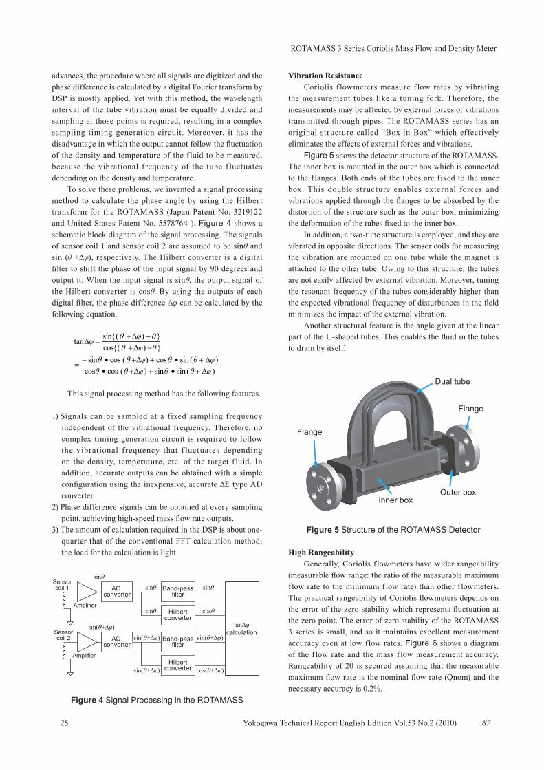
Vibration ResistanceCoriolis f lowmeters measure f low rates by vibrating
the measurement tubes like a tuning fork. Therefore, the measurements may be affected by external forces or vibrations transmitted through pipes. The ROTAMASS series has an original structure called “Box-in-Box” which effectively eliminates the effects of external forces and vibrations.
Figure 5 shows the detector structure of the ROTAMASS. The inner box is mounted in the outer box which is connected to the flanges. Both ends of the tubes are fixed to the inner box. This double structure enables external forces and vibrations applied through the flanges to be absorbed by the distortion of the structure such as the outer box, minimizing the deformation of the tubes fixed to the inner box.
In addition, a two-tube structure is employed, and they are vibrated in opposite directions. The sensor coils for measuring the vibration are mounted on one tube while the magnet is attached to the other tube. Owing to this structure, the tubes are not easily affected by external vibration. Moreover, tuning the resonant frequency of the tubes considerably higher than the expected vibrational frequency of disturbances in the field minimizes the impact of the external vibration.
Another structural feature is the angle given at the linear part of the U-shaped tubes. This enables the fluid in the tubes to drain by itself.
Figure 5 Structure of the ROTAMASS Detector
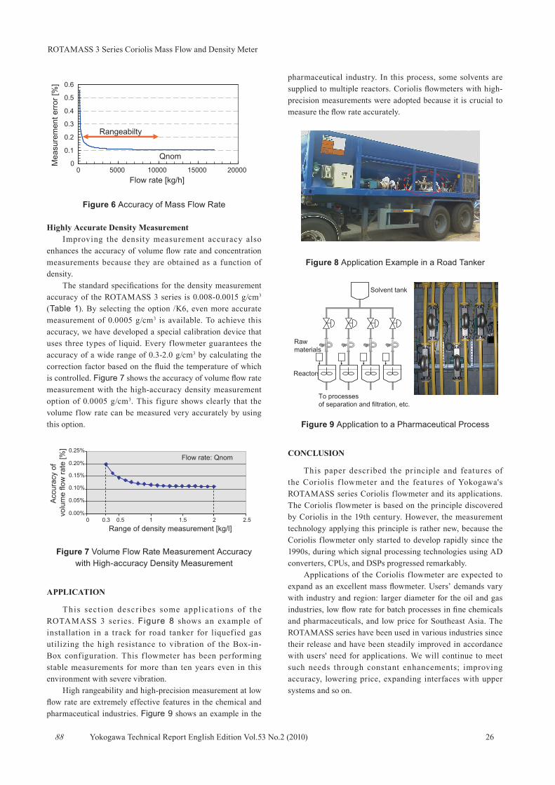
High RangeabilityGenerally, Coriolis f lowmeters have wider rangeability
(measurable flow range: the ratio of the measurable maximum flow rate to the minimum flow rate) than other flowmeters. The practical rangeability of Coriolis flowmeters depends on the error of the zero stability which represents fluctuation at the zero point. The error of zero stability of the ROTAMASS 3 series is small, and so it maintains excellent measurement accuracy even at low flow rates. Figure 6 shows a diagram of the f low rate and the mass f low measurement accuracy. Rangeability of 20 is secured assuming that the measurable maximum flow rate is the nominal flow rate (Qnom) and the necessary accuracy is 0.2%.
( ){ }( ){ }
)(sinsin)(coscos)(sincos)cos (sin
−cossintan
∆φθθ∆φθθ∆φθθ∆φθθ
θ∆φθ∆φ
∆φ
+•++•+•++•−
=
+−+
=θθ
AD converter
AD converter
Band-passfilter
Band-passfilter
Hilbertconverter
Hilbertconverter
tan∆φcalculation
Sensorcoil 1
Sensorcoil 2
Amplifier
Amplifier
sinθ
sin(θ+∆φ)
sinθ
sinθ
sinθ
cosθ
sin(θ+∆φ)
sin(θ+∆φ)
sin(θ+∆φ)
cos(θ+∆φ)
Dual tube
Inner boxOuter box
Flange
Flange
25 87
ROTAMASS 3 Series Coriolis Mass Flow and Density Meter
Yokogawa Technical Report English Edition Vol.53 No.2 (2010)
Figure 6 Accuracy of Mass Flow Rate
Highly Accurate Density MeasurementImproving the density measurement accuracy also
enhances the accuracy of volume flow rate and concentration measurements because they are obtained as a function of density.
The standard specifications for the density measurement accuracy of the ROTAMASS 3 series is 0.008-0.0015 g/cm3 (Table 1). By selecting the option /K6, even more accurate measurement of 0.0005 g/cm3 is available. To achieve this accuracy, we have developed a special calibration device that uses three types of liquid. Every f lowmeter guarantees the accuracy of a wide range of 0.3-2.0 g/cm3 by calculating the correction factor based on the fluid the temperature of which is controlled. Figure 7 shows the accuracy of volume flow rate measurement with the high-accuracy density measurement option of 0.0005 g/cm3. This figure shows clearly that the volume flow rate can be measured very accurately by using this option.
Figure 7 Volume Flow Rate Measurement Accuracy with High-accuracy Density Measurement
APPLICATION
This sect ion descr ibes some appl icat ions of the ROTAMASS 3 ser ies. Figure 8 shows an example of installation in a track for road tanker for liquefied gas utilizing the high resistance to vibration of the Box-in-Box configuration. This f lowmeter has been performing stable measurements for more than ten years even in this environment with severe vibration.
High rangeability and high-precision measurement at low flow rate are extremely effective features in the chemical and pharmaceutical industries. Figure 9 shows an example in the
pharmaceutical industry. In this process, some solvents are supplied to multiple reactors. Coriolis flowmeters with high-precision measurements were adopted because it is crucial to measure the flow rate accurately.
Figure 8 Application Example in a Road Tanker
Figure 9 Application to a Pharmaceutical Process
CONCLUSION
This paper described the principle and features of the Coriolis f lowmeter and the features of Yokogawa's ROTAMASS series Coriolis flowmeter and its applications. The Coriolis flowmeter is based on the principle discovered by Coriolis in the 19th century. However, the measurement technology applying this principle is rather new, because the Coriolis flowmeter only started to develop rapidly since the 1990s, during which signal processing technologies using AD converters, CPUs, and DSPs progressed remarkably.
Applications of the Coriolis f lowmeter are expected to expand as an excellent mass flowmeter. Users’ demands vary with industry and region: larger diameter for the oil and gas industries, low flow rate for batch processes in fine chemicals and pharmaceuticals, and low price for Southeast Asia. The ROTAMASS series have been used in various industries since their release and have been steadily improved in accordance with users' need for applications. We will continue to meet such needs through constant enhancements; improving accuracy, lowering price, expanding interfaces with upper systems and so on.
Flow rate [kg/h]
Rangeabilty
Qnom
Mea
sure
men
t err
or [%
]
0 5000 10000 15000 20000
0.6
0.5
0.4
0.3
0.2
0.1
0
0.25%
0.20%
0.15%
0.10%
0.05%
0.00%
Flow rate: Qnom
2.521.510.50.30
Acc
urac
y of
vo
lum
e flo
w ra
te [%
]
Range of density measurement [kg/l]
To processes of separation and filtration, etc.
Solvent tank
Reactors
Raw materials
2688