User’s Manual DTSX200 Communications(Modbus) Guide · DTSX200 Communications(Modbus) Guide IM...
52
User’s Manual IM 39J06B45-02E DTSX200 Communications(Modbus) Guide IM 39J06B45-02E 4th Edition
Transcript of User’s Manual DTSX200 Communications(Modbus) Guide · DTSX200 Communications(Modbus) Guide IM...

User’s Manual
IM 39J06B45-02E
DTSX200 Communications(Modbus) Guide
IM 39J06B45-02E 4th Edition

IM 39J06B45-02E
Blank Page

< Introduction > i
IM 39J06B45-02E
Introduction
About this Manual Thank you for purchasing the DTSX200 Distributed Temperature Sensor. This document describes the (Modbus) communications function of the DTSX200. Read it carefully before using the function to ensure proper use. You may also refer to the following manuals for other information related to the DTSX200.
Manual name Document No. Description DTSX200 Distributed Temperature Sensor Guide IM 39J06B45-01E
This document describes the functions, operation and usage precautions of the DTSX200 Distributed Temperature Sensor.
DTAP200 DTSX200 Control Visualization Software Guide
IM 39J02B45-01E
This document describes the functions, operation and usage precautions of the DTSX200 Control Visualization Software, which can be used to configure the DTSX200 Distributed Temperature Sensor and display its measurement result.
DTAP200 DTSX200 Control Visualization Software LAS 2.0 Data Conversion Guide
IM 39J02B45-02E This document describes the functions, operation and usage precautions of the software for converting and transmitting measurement data of the DTSX200 Distributed Temperature Sensor in LAS format.
Caution YOKOGAWA reserves the right to make improvements in the manuals and product at any time, without notice or obligation. If you have any questions, or you find mistakes or omissions in the manuals, please contact our sales representative or your local distributor. No part of the manual may be transferred or reproduced without prior written consent from YOKOGAWA.
Trademarks The following names are trademarks or registered trademarks of their respective holders • DTSX, STARDOM and CENTUM are trademarks of Yokogawa Electric Corporation. • Ethernet is a registered trademark of Xerox Corporation. • Modbus is a registered trademark of AEG Schneider.

IM 39J06B45-02E
Blank Page

< CONTENTS > iii
IM 39J06B45-02E
CONTENTS Introduction ................................................................................................ i CONTENTS ............................................................................................... iii 1. Overview of the Communications Function .................................. 1 2. Specifications ................................................................................... 3
2.1. Communications Interface Specifications ................................................ 3 2.1.1. Ethernet ............................................................................................ 3 2.1.2. RS-232C .......................................................................................... 3
2.2. Modbus Communications Protocol Specifications ................................. 4 2.2.1. Modbus/TCP .................................................................................... 4 2.2.2. Modbus Serial ..................................................................................... 4
3. Communications Setup ................................................................... 5 3.1. Modbus/TCP ................................................................................................ 5
3.1.1. Settings ............................................................................................ 5 3.1.2. Setup Procedure .............................................................................. 5
3.2. Modbus Serial Communications ................................................................ 8 3.2.1. Modbus Communications Related Settings ..................................... 8 3.2.2. Setup Procedure .............................................................................. 8
4. Modbus Communications Protocol .............................................. 11 4.1. Overview..................................................................................................... 11 4.2. Message Structure .................................................................................... 11
4.2.1. Device Number .............................................................................. 11 4.2.2. Function Code ................................................................................ 11 4.2.3. Data ................................................................................................ 11 4.2.4. Error Check Code .......................................................................... 12
4.3. Slave Response ......................................................................................... 12 4.3.1. Normal Response .......................................................................... 12 4.3.2. Exception Response ...................................................................... 12 4.3.3. No Response ................................................................................. 13
4.4. Function Codes ......................................................................................... 13 5. Message Description ..................................................................... 15
5.1. Read Holding Registers ............................................................................ 15 5.1.1. Message Structure ......................................................................... 15 5.1.2. Function Description ...................................................................... 15
DTSX200 Communications(Modbus) Guide IM 39J06B45-02E

< CONTENTS > iv
IM 39J06B45-02E
5.1.3. Example of Message Exchange .................................................... 15 5.2. Read Input Registers ................................................................................. 16
5.2.1. Message Structure ......................................................................... 16 5.2.2. Function Description ...................................................................... 16 5.2.3. Example of Message Exchange .................................................... 16
5.3. Write Single Register ................................................................................ 17 5.3.1. Message Structure ......................................................................... 17 5.3.2. Function Description ...................................................................... 17 5.3.3. Example of Message Exchange .................................................... 17
5.4. Write Multiple Registers............................................................................ 18 5.4.1. Message Structure ......................................................................... 18 5.4.2. Function Description ...................................................................... 18 5.4.3. Example of Message Exchange .................................................... 18
6. Address Map ................................................................................... 19 6.1. Handling of Fractional Data ...................................................................... 19 6.2. Holding Register Address Map ................................................................ 19
6.2.1. List of Holding Registers ................................................................ 19 6.2.2. Description of Holding Registers .................................................... 20
6.3. Input Register Address Map ..................................................................... 38 6.3.1. List of Input Registers .................................................................... 38 6.3.2. Description of Input Registers ........................................................ 38
Revision Information ................................................................................. i

< 1. Overview of the Communications Function> 1
IM 39J06B45-02E
1. Overview of the Communications Function
The DTSX200 supports communications based on the Modbus protocol via built-in Ethernet and RS-232C ports as communications interfaces. Using Modbus communications, a client/master can configure, control, as well as retrieve status information and measurement data from a remote DTSX200. The figure below shows an example system configuration.
DTSX200
PC PC
Ethernet
Modbus Serial(ASCII, RTU)
Modbus/TCP Modbus/TCP Modbus/TCP
STARDOM,CENTUM
Modbus/TCP
Control device
RS-232C
PC
If connection to the DTSX200 is by Ethernet, the Modbus/TCP communications protocol is used, the DTSX200 runs as a Modbus/TCP server and can connect to a maximum of four client devices. If connection to the DTSX200 is by RS-232C, the DTSX200 runs as a slave device and communicates one-to-one with a master device. Both the RTU and ASCII serial transmission modes are supported. For RS-232C communications, a slave address must be defined for the DTSX200.

IM 39J06B45-02E
Blank Page

< 2. Specification> 3
IM 39J06B45-02E
2. Specifications 2.1. Communications Interface Specifications
2.1.1. Ethernet
Item Specifications Connector type RJ-45 connector Number of ports 1 Electrical and mechanical specifications IEEE802.3 compliant
Transmission mode 100BASE-TX/10BASE-T
2.1.2. RS-232C
Item Specifications Connector type RJ-45 connector
Number of ports 3 (COM1, COM2 and COM3) * COM1 and COM2 ports are available for Modbus serial communications.
Electrical and mechanical specifications EIA RS-232 compliant
Transmission mode Full-duplex Synchronization Start-stop synchronization
Baud rate 1200, 2400, 4800, 9600, 19200, 38400, 57600 or 115200 bps (selectable) * The COM2 port supports baud rates up to 38400 bps.
Character length 7 or 8 bits Parity None, even or odd Stop bits 1 bit or 2 bits Flow control None, rts/cts or xon/xoff

< 2. Specification> 4
IM 39J06B45-02E
2.2. Modbus Communications Protocol Specifications
2.2.1. Modbus/TCP The DTSX200 supports the Modbus/TCP server function (equivalent to the Modbus slave function) and allows connection to a maximum of four client devices. It also has a timeout function, which automatically disconnects a client device if there is no communication for a specified timeout interval or longer. To maintain connection, communicate with the DTSX200 regularly.
Item Specification Transmission media Ethernet Transmission mode RTU mode Error detection Compliant with TCP/IP error-checking specification Port number used 502 * can be changed from the Maintenance web page Number of clients 4 max. Communication timeout 5 to 1800 seconds
2.2.2. Modbus Serial The DTSX200 supports the Modbus slave function.
Item Specification Transmission media RS-232C Transmission mode RTU mode or ASCII mode (selectable) Slave address 1 to 247 Port number used COM1 or COM2 (selectable) Baud rate Selectable from 1200, 2400, 4800, 9600, 19200, 38400, 57600 or
115200 bps (selectable) * The COM2 port supports baud rates up to 38400 bps.
Data bits 7 or 8 bits. * 8 bits must be specified for RTU transmission mode.
Parity None, even or odd Stop bits 1 bit or 2 bits Flow control None, rts/cts or xon/xoff (selectable) Data interval 24-bit time or shorter Error detection CRC-16 (for RTU mode) and LRC (for ASCII mode)

< 3. Communication Setup> 5
IM 39J06B45-02E
3. Communications Setup 3.1. Modbus/TCP
This section describes how to set up the DTSX200 for Modbus/TCP communications.
3.1.1. Settings Setting Setting Range
Port Number 502 or 1024 to 65535 Communication timeout interval 5 to 1800 seconds
3.1.2. Setup Procedure 1. Open the web application in Maintenance (Auth) mode.
SEE ALSO For details, see Subsection B6.1.4, “How to Transit between Operation States” of Chapter B6, “System Configuration” of the DTSX200 Guide (IM 39J06B45-01E).
2. Click Application Setting – Modbus TCP to display the [Modbus TCP] page.

< 3. Communication Setup> 6
IM 39J06B45-02E
3. Specify the port number for Modbus/TCP communications in [Port Number] and the communication timeout duration in [Comm Timeout]. Select “yes” for [Port Enable] to enable the port number for Modbus/TCP communications. After you have completed all required settings, click the [Set] button. Clicking the [Initialize] button reverts all settings to their default values, namely, 502 for [Port Number], 600 for [Comm Timeout] and “yes” for [Port Enable] respectively.
4. When the following page is displayed, click [OK].

< 3. Communication Setup> 7
IM 39J06B45-02E
5. When the following page is displayed, click Operations-Reboot to reboot the system in online mode.
SEE ALSO For more details, see Subsection B6.1.4, “How to Transit between Operation States” of Chapter B6, “System Configuration” of the DTSX200 Guide (IM 39J06B45-01E).

< 3. Communication Setup> 8
IM 39J06B45-02E
3.2. Modbus Serial Communications This section describes how to perform setup for Modbus serial communications.
3.2.1. Modbus Communications Related Settings Setting Setting Range
Slave Address 1 to 247 Protocol rtu or ascii
SEE ALSO For details on serial communications related settings, see Subsection B6.4.8, “Serial Port Configuration (Serial)” of the DTSX200 Guide (IM 39J06B45-01E).
3.2.2. Setup Procedure 1. Open the web application in Maintenance (Auth) mode.
SEE ALSO For more details, see Subsection B6.1.4, “How to Transit between Operation States” of Chapter B6, “System Configuration” of the DTSX200 Guide (IM 39J06B45-01E).
2. Click Application Setting – Modbus Serial to display the Modbus Serial page.

< 3. Communication Setup> 9
IM 39J06B45-02E
3. Specify the [Slave Address] and [Protocol], and then click the [Set] button. To revert these settings to their default values, click the [Initialize] button. This will revert [Slave Address] to 1 and [Protocol] to “rtu”.
4. When the following page is displayed, click the [OK] button.

< 3. Communication Setup> 10
IM 39J06B45-02E
5. When the following page is displayed, click Operations-Reboot to reboot in online mode.
SEE ALSO For details, see Subsection B6.1.4, “How to Transit between Operation States” of Chapter B6, “System Configuration” of the DTSX200 Guide (IM 39J06B45-01E).

< 4. Modbus Communications Protocol> 11
IM 39J06B45-02E
4. Modbus Communications Protocol 4.1. Overview
In a communications system based on the Modbus protocol, the master initiates a transaction and the slave responds to it. The communications protocol is as follows: 1) A master sends a request message to slaves. 2) Each slave compares the device number in the received message to its own device
number. 3) If the device numbers match, the slave sends a response message. 4) If the device numbers do not match, the slave discards the received request
message and waits for the next request message. By specifying a device number in a request message, a master can communicate with a specific slave even when multiple slaves are connected to the same line.
4.2. Message Structure Each request message or response message comprises four fields, namely a device number, a function code, a data field and an error check code, which are transmitted sequentially in the given order. Modbus defines two serial transmission modes, namely, the RTU mode and the ASCII mode, with different message formats. The ASCII mode permits only data comprising ASCII characters 0-9 and A-F.
Device number (1 byte)Function code (1 byte)
Data (n bytes)Error check code (CRC) (2 bytes)
RTU mode
Start (1 character): colon (:)Device number (2 characters)Function code (2 characters)
Data (n characters)Error check code (LRC) (2 characters)
End (2 characters): CR+LF
ASCII mode Each message field is described in more details below.
4.2.1. Device Number The device number specifies a slave. Only the DTSX200 with a matching device number will process the request message.
4.2.2. Function Code The function code specifies the function to be executed by the slave.
SEE ALSO For more details on the function code, see Section 4.4, “Function Codes.”
4.2.3. Data The data field contains data required for executing the function defined by the function code. The data structure varies with the function code. Each DTSX200 setting is assigned a unique register number. To read or write a setting, specify its register number. Register numbers must be specified as relative addresses in transmitted messages.

< 4. Modbus Communications Protocol> 12
IM 39J06B45-02E
The relative address of a register is given by the formula: Relative address = Last 5 digits of the register number − 1
For example, to specify register number 400003 as a parameter for a function code, you should specify relative address 00002 in the message:
Relative address = (last 5 digits of 400003) − 1 = 0002
4.2.4. Error Check Code The error check code is used for detecting message errors (bit changes), if any, introduced during signal transmission. CRC (Cyclic Redundancy Check) is used in RTU serial transmission mode. LRC (Longitudinal Redundancy Check) is used in ASCII serial transmission mode.
4.3. Slave Response
4.3.1. Normal Response If no error occurs in relation to the function requested in a properly received request message, the slave creates and returns a normal response message. The message structure is as described in Section 4.2. The content of the data field varies with the function code.
SEE ALSO For details on the function code, see Section 4.4, “Function Codes.”
4.3.2. Exception Response If a request message contains a non-transmission-related error (such as a non-existent function code), the slave creates and returns an error response message without executing the request. The figure below shows the structure of an error response message. In an error response, the function code is 80H higher than the function code of the original request.
Device numberFunction code+80H
Error codeError check code (CRC)
RTU mode
Start (1 character): colon (:)Device number
Function code+80H
Error codeError check code (LRC)
End (2 characters): CR+LF
ASCII mode The error codes are listed in the table below.
Table: Error Codes Error Code Error Description
01H Invalid function code The specified function code is non-existent. Check the specified function code.
02H Invalid address for coil or register The specified relative address of a register number is not allowed for the specified function code.
03H Invalid number of registers The specified number of registers is too large and covers a range containing non-existent register numbers.

< 4. Modbus Communications Protocol> 13
IM 39J06B45-02E
4.3.3. No Response A slave ignores a request message and returns no response if: - The device number specified in the request message does not match slave’s own
device number; - The error check code does not match; or - A transmission error (such as a parity error) is detected.
4.4. Function Codes In the Modbus protocol, each function code can only act on certain allocated register numbers. The table below shows the mapping between function codes and register numbers for the DTSX200.
Table: Mapping between Function Codes and Addresses Function Code Register Number
Number Function Object Number Description 03H Read (contiguous) Holding registers 4XXXXX Read-write word data 04H Read (contiguous) Input registers 3XXXXX Read-only word data 06H Write Holding register 4XXXXX Read-write word data 10H Write (contiguous) Holding registers 4XXXXX Read-write word data

IM 39J06B45-02E
Blank Page
< 5. Message Description> 15
IM 39J06B45-02E
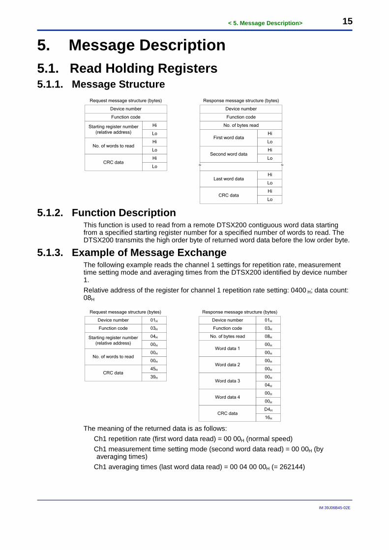
5. Message Description 5.1. Read Holding Registers 5.1.1. Message Structure
Device number
Function code
Starting register number(relative address)
Hi
Lo
No. of words to readHi
Lo
CRC dataHi
Lo
Request message structure (bytes)
Device number
Function code
First word dataHi
Lo
Last word dataHi
Lo
CRC dataHi
Lo
Response message structure (bytes)
No. of bytes read
Second word dataHi
Lo
~ ~
5.1.2. Function Description
This function is used to read from a remote DTSX200 contiguous word data starting from a specified starting register number for a specified number of words to read. The DTSX200 transmits the high order byte of returned word data before the low order byte.
5.1.3. Example of Message Exchange The following example reads the channel 1 settings for repetition rate, measurement time setting mode and averaging times from the DTSX200 identified by device number 1. Relative address of the register for channel 1 repetition rate setting: 0400 H; data count: 08H
Device number
Function code
Starting register number(relative address)
No. of words to read
CRC data
01H Device number
Function code
Word data 100H
00H
Word data 400H
00H
CRC dataD4H
16H
No. of bytes read
Word data 200H
00H
01H
03H
08H
Word data 300H
04H
Request message structure (bytes) Response message structure (bytes)
03H
04H
00H
00H
00H
45H
39H
The meaning of the returned data is as follows:
Ch1 repetition rate (first word data read) = 00 00H (normal speed) Ch1 measurement time setting mode (second word data read) = 00 00H (by averaging times)
Ch1 averaging times (last word data read) = 00 04 00 00H (= 262144)

< 5. Message Description> 16
IM 39J06B45-02E
5.2. Read Input Registers 5.2.1. Message Structure
Device number
Function code
Starting register number(relative address)
Hi
Lo
No. of words to readHi
Lo
CRC dataHi
Lo
Request message structure (bytes)
Device number
Function code
First word dataHi
Lo
Last word dataHi
Lo
CRC dataHi
Lo
Response message structure (bytes)
No. of bytes read
Second word dataHi
Lo
~ ~
5.2.2. Function Description
This function is used to read from a remote DTSX200 contiguous words of read-only data starting from a specified starting register number for a specified number of words to read. The DTSX200 transmits the high order byte of returned word data before the low order byte.
5.2.3. Example of Message Exchange The following example reads status information and measurement progress information (Active channel number and progress percentage) from the DTSX200 identified by device number 1. Relative address of the status information register: 0000 H; Data count: 06H
Device number
Function code
Starting register number(relative address)
No. of words to read
CRC data
01H Device number
Function code
Word data 1
CRC data
No. of bytes read
Word data 2
Word data 3
Request message structure (bytes) Response message structure (bytes)
04H
00H
00H
0BH
B0H
00H
03H
00H
01H
4CH
F2H
00H
01H
01H
04H
06H
01H
43H
The meaning of the returned data is as follows:
Status information (read word data 1) = 00 01H (measurement in progress) Active channel number (read word data 2) = 00 01H (Ch1) Channel measurement progress percentage (read word data 3) = 01 43H (32.3%)
SEE ALSO Response messages cannot contain fractional data values so the data value 32.3 in the above example is returned as data value 323 (143H). For details on the handling of the respective data, see Chapter 6, “Address Map.”

< 5. Message Description> 17
IM 39J06B45-02E
5.3. Write Single Register 5.3.1. Message Structure
Device number
Function code
Register number(relative address)
Hi
Lo
Word data to writeHi
Lo
CRC dataHi
Lo
Request message structure (bytes)
Device number
Function code
Register number(relative address)
Hi
Lo
Word data writtenHi
Lo
CRC dataHi
Lo
Response message structure (bytes)
5.3.2. Function Description
This function is used to write one word of data to a specified register number in a remote DTSX200. The high order byte of the word data to be written must be transmitted to DTSX200 before the low order byte.
5.3.3. Example of Message Exchange The following example writes the power save mode setting value to the DTSX200 identified by device number 1. Relative address of the power save mode setting register: 0100H Power save mode setting value: 0001H (ON)
Device number
Function code
Register number(relative address)
01H
00H
Word data to write00H
01H
CRC data49H
F6H
Request message structure (bytes)
Device number
Function code
Register number(relative address)
Word data written
CRC data
Response message structure (bytes)
01H
06H
01H
00H
00H
01H
49H
F6H
01H
06H

< 5. Message Description> 18
IM 39J06B45-02E
5.4. Write Multiple Registers 5.4.1. Message Structure
Device number
Function code
Starting register number(relative address)
Hi
Lo
No. of words writtenHi
Lo
CRC dataHi
Lo
Response message structure (bytes)
Device number
Function code
Starting register number(relative address)
Hi
Lo
Last word dataHi
Lo
CRC dataHi
Lo
Request message structure (bytes)
No. of bytes to write
Second word dataHi
Lo
~
No. of words to writeHi
Lo
First word data Hi
Lo
~
5.4.2. Function Description
This function is used to write to a remote DTSX200 contiguous word data starting from a specified starting register number for a specified number of words to write. The high order byte of the word data to be written must be transmitted to DTSX200 before the low order byte.
5.4.3. Example of Message Exchange The following example writes the fiber length of zone 1 of channel 1 to the DTSX200 identified by device number 1. It sets the fiber length to 10000.0 m. Relative address of register for fiber length of zone 1 of channel 1: 0802 H; Data count: 02H Ch1 zone 1 fiber length setting value: 00002710H (=10000D)
SEE ALSO Request messages cannot contain decimal points so data value 1000.0 in the above example must be transmitted as data value 100000. For details on the handling of the data, see Chapter 6, “Address Map.”
Device number
Function code
Starting register number(relative address)
08H
02H
No. of words written00H
02H
CRC dataE2H
68H
Response message structure (bytes)
Device number
Function code
Starting register number(relative address)
08H
02H
Word data 227H
10H
CRC data0FH
8AH
Request message structure (bytes)
No. of bytes to write
No. of words to write00H
02H
Word data 100H
00H
01H
10H
04H
01H
10H

< 6. Address Map> 19
IM 39J06B45-02E
6. Address Map 6.1. Handling of Fractional Data
Some DTSX200 settings allow fractional values but transmission of fractional values in messages is not allowed. In the address map tables in the following pages, a setting parameter allowing fractional values is specified with its fixed number of decimal places. When handling fractional data, calculate its proper value using its fixed number of decimal places as shown in the following examples. Example 1: Reading the fiber length setting for zone 1 of channel 1 (register number: 402051) If the DTSX200 returns a value of 1000 for this parameter, which has 1 decimal place, the fiber length of zone 1 of channel 1 is given by: 1000÷10 = 100.0 Example 2: Writing the fiber length setting for zone 1 of channel (register number: 402051) To set the fiber length of zone 1 of channel 1 to 100.0, the value to be written to the DTSX200 for this parameter, which has 1 decimal place, is given by: 100.0x10 = 1000
6.2. Holding Register Address Map 6.2.1. List of Holding Registers
Register Number Function 400001 to 400002 Execution control functions 400017 Data conversion function 400033 Temperature calibration function 400065 Initialization function 400257 — Measurement sequence control settings 400513 — Measurement sequence table settings 401025 —
Channel settings
Measurement condition settings 402049 — Fiber settings 412289 — Alarm settings 422529 — Tag data settings 432769 — Data conversion function Data conversion function selection 433025 — LAS data conversion Header settings 435329 — Conversion and transmission settings 449153 — Latest measurement
data monitoring area
Channel number for latest measurement data 449155 — Tag data 449355 — Alarm information 449409 — Individual channel measurement data monitoring area 453505 — Measurement data information
< 6. Address Map> 20
IM 39J06B45-02E
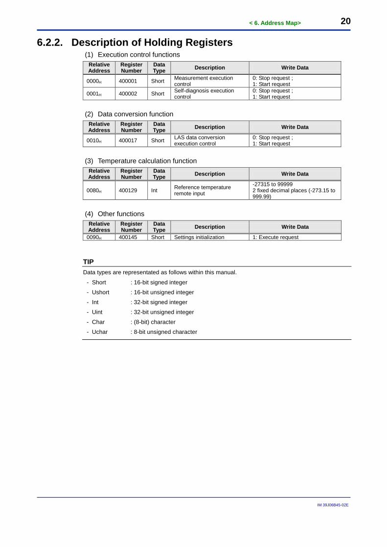
6.2.2. Description of Holding Registers (1) Execution control functions
Relative Address
Register Number
Data Type Description Write Data
0000H 400001 Short Measurement execution control
0: Stop request ; 1: Start request
0001H 400002 Short Self-diagnosis execution control
0: Stop request ; 1: Start request
(2) Data conversion function
Relative Address
Register Number
Data Type Description Write Data
0010H 400017 Short LAS data conversion execution control
0: Stop request ; 1: Start request
(3) Temperature calculation function
Relative Address
Register Number
Data Type Description Write Data
0080H 400129 Int Reference temperature remote input
-27315 to 99999 2 fixed decimal places (-273.15 to 999.99)
(4) Other functions
Relative Address
Register Number
Data Type Description Write Data
0090H 400145 Short Settings initialization 1: Execute request
TIP Data types are representated as follows within this manual.
- Short : 16-bit signed integer
- Ushort : 16-bit unsigned integer
- Int : 32-bit signed integer
- Uint : 32-bit unsigned integer
- Char : (8-bit) character
- Uchar : 8-bit unsigned character

< 6. Address Map> 21
IM 39J06B45-02E
(5) Measurement sequence control settings Relative Address
Register Number
Data Type Description Read/Write Data No.
0100H 400257 Short Power save mode 0: Off; 1: On 1 0101H 400258 Short Sequence mode 0: Single; 1: Continuous 2
0102H 400259 Short Repetition mode 0: Sequence interval; 1: Sequence start time 3
0103H 400260 Short Sequence start time repetition
0: 1 cycle; 1: every day 4
0104H 400261 Int Sequence interval 0 to 86400 5
0106H 400263 Short Use flag of sequence start time 1 0: Off; 1: On 6
0108H 400265 Short×2 Sequence start time 1 Hour (data 1): 0 to 23
Minute (data 2): 0 to 59 7
010AH 400267 Short Use flag of sequence start time 2 0: Off; 1: On 6
010CH 400269 Short×2 Sequence start time 2 Hour (data 1): 0 to 23
Minute (data 2): 0 to 59 7
010EH 400271 Short Use flag of sequence start time 3 0: Off; 1: On 6
0110H 400273 Short×2 Sequence start time 3 Hour (data 1): 0 to 23
Minute (data 2): 0 to 59 7
0112H 400275 Short Use flag of sequence start time 4 0: Off; 1: On 6
0114H 400277 Short×2 Sequence start time 4 Hour (data 1): 0 to 23
Minute (data 2): 0 to 59 7
0116H 400279 Short Use flag of sequence start time 5 0: Off; 1: On 6
0118H 400281 Short×2 Sequence start time 5 Hour (data 1): 0 to 23
Minute (data 2): 0 to 59 7
011AH 400283 Short Use flag of sequence start time 6 0: Off; 1: On 6
011CH 400285 Short×2 Sequence start time 6 Hour (data 1): 0 to 23
Minute (data 2): 0 to 59 7
TIP - These parameters cannot be modified during measurement.
- The screen capture below maps the measurement condition settings displayed in the DTSX200 Control Visualization Software to their allocated Modbus registers. The labels shown in the screen capture map to the “No.” column in the above table. Example: The field labeled as (5)-1 in the screen capture refers to the power save mode in the above table.

< 6. Address Map> 22
IM 39J06B45-02E
(6) Measurement sequence table settings Relative Address
Register Number
Data Type Description Read/Write Data No.
0200H 400513 Short Sequence 1 Use flag 0: Off; 1: On 1
0201H 400514 Short Sequence 1 Principle 0: Single-end; 1: Double-end 2
0202H 400515 Short Sequence 1 Channel (Near) 1: Ch1, …, 16: Ch16 3 0203H 400516 Short Sequence 1 Channel (Far) 1: Ch1, …, 16: Ch16 4 0204H 400517 Short Sequence 1 Interval 0 to 3600 5 0210H — 400529 — Sequence 2 settings (same data structure as sequence 1) - 0220H — 400545 — Sequence 3 settings (same data structure as sequence 1) - 0230H — 400561 — Sequence 4 settings (same data structure as sequence 1) - 0240H — 400577 — Sequence 5 settings (same data structure as sequence 1) - 0250H — 400593 — Sequence 6 settings (same data structure as sequence 1) - 0260H — 400609 — Sequence 7 settings (same data structure as sequence 1) - 0270H — 400625 — Sequence 8 settings (same data structure as sequence 1) - 0280H — 400641 — Sequence 9 settings (same data structure as sequence 1) - 0290H — 400657 — Sequence 10 settings (same data structure as sequence 1) - 02A0H — 400673 — Sequence 11 settings (same data structure as sequence 1) - 02B0H — 400689 — Sequence 12 settings (same data structure as sequence 1) - 02C0H — 400705 — Sequence 13 settings (same data structure as sequence 1) - 02D0H — 400721 — Sequence 14 settings (same data structure as sequence 1) - 02E0H — 400737 — Sequence 15 settings (same data structure as sequence 1) - 02F0H — 400753 — Sequence 16 settings (same data structure as sequence 1) -
TIP - These parameters cannot be modified during measurement.
- The screen capture below maps the sequence table settings displayed in the DTSX200 Control Visualization Software to their allocated Modbus registers. The labels shown in the screen capture map to the “No.” column in the above table. Example: The field labeled as (6)-1 in the screen capture refers to the Sequence 1 Use Flag setting in the above table.

< 6. Address Map> 23
IM 39J06B45-02E
(7) Channel settings Relative Address
Register Number
Data Type Description Read/Write Data No.
0400H 401025 Short Ch1 repetition rate 0: Standard rate; 1: Fast rate 1
0401H 401026 Short Ch1 measurement time setting mode
0: Averaging times; 1: Duration 2
0402H 401027 Int Ch1 averaging times 4096 to 268435456 3 0404H 401029 Int Ch1 measurement time 1 to 86400 4
0406H 401031 Short Ch1 distance range 1000: 1 km; 2000: 2 km; 3000: 3 km; 4000: 4 km; 6000: 6 km
5
0407H 401032 Short Ch1 sampling resolution 10: 10 cm; 20: 20 cm; 50: 50 cm; 100: 1 m 6
0408H 401033 Short Ch1 fiber failure detection 0: Off; 1: On 7
0409H 401034 Short Ch1 fiber failure threshold level
0 to 999 1 fixed decimal place (0.0 to 99.9)
8
040CH 401037 Int Ch1 switch length 0 to 300000 1 fixed decimal place (0.0 to 30000.0)
9
040EH 401039 Int Ch1 well inlet position 0 to 300000 1 fixed decimal place (0.0 to 30000.0)
10
0410H 401041 Int Fiber all length 0 to 300000 1 fixed decimal place (0.0 to 30000.0)
11
0412H 401043 Short Calculation Range 0: All Data; 1: Total Length 12
0414H 401045 Short Ch1 ST-AS differential loss setting type for double-ended measurement
0: Measurement; 1: Setting 13
0415H 401046 Short Ch1 ST-AS differential loss for double-ended measurement
-9999 to 9999 3 fixed decimal places (-9.999 to 9.999)
14
0416H 401047 Int Ch1 distance of W to P1 for double-ended measurement
0 to 300000 1 fixed decimal place (0.0 to 30000.0)
15
0418H 401049 Short Ch1 near end averaging distance for double-ended measurement
50 to 200 1 fixed decimal place (5.0 to 20.0)
16
0419H 401050 Short Ch1 far end distance type for double-ended measurement
0: W to P2; 1: E to P2 17
041AH 401051 Int Ch1 distance of W to P2 for double-ended measurement
0 to 300000 1 fixed decimal place (0.0 to 30000.0)
18
041CH 401053 Int Ch1 distance of E to P2 for double-ended measurement
0 to 300000 1 fixed decimal place (0.0 to 30000.0)
19
041EH 401055 Short Ch1 far end averaging distance for double-ended measurement
50 to 200 1 fixed decimal place (5.0 to 20.0)
20
0440H — 401089 — Channel 2 settings (same data structure as channel 1) - 0480H — 401153 — Channel 3 settings (same data structure as channel 1) - 04C0H — 401217 — Channel 4 settings (same data structure as channel 1) - 0500H — 401281 — Channel 5 settings (same data structure as channel 1) - 0540H — 401345 — Channel 6 settings (same data structure as channel 1) - 0580H — 401409 — Channel 7 settings (same data structure as channel 1) - 05C0H — 401473 — Channel 8 settings (same data structure as channel 1) - 0600H — 401537 — Channel 9 settings (same data structure as channel 1) - 0640H — 401061 — Channel 10 settings (same data structure as channel 1) - 0680H — 401665 — Channel 11 settings (same data structure as channel 1) - 06C0H — 401729 — Channel 12 settings (same data structure as channel 1) - 0700H — 401793 — Channel 13 settings (same data structure as channel 1) - 0740H — 401857 — Channel 14 settings (same data structure as channel 1) - 0780H — 401921 — Channel 15 settings (same data structure as channel 1) - 07C0H — 401985 — Channel 16 settings (same data structure as channel 1) -

< 6. Address Map> 24
IM 39J06B45-02E
TIP - These parameters cannot be modified during measurement.
- Averaging times should be specified as a multiple of 4096. Otherwise, it will be rounded down to the nearest multiple of 4096 with the remainder discarded.
- Sampling resolution of 10 cm is not allowed if the specified distance range is 4 km or longer. If you specify the distance range as 4 km or longer when the specified sampling resolution is 10 cm, the sample resolution will be changed automatically to 1m.
- The screen captures below map the channel settings displayed in the DTSX200 Control Visualization Software to their allocated Modbus registers. The labels shown in the screen captures map to the “No.” column in the above table. Example: The field labeled as (7)-1 in the screen capture refers to the repetition rate of channel 1.

< 6. Address Map> 25
IM 39J06B45-02E
(8) Fiber settings Relative Address
Register Number
Data Type Description Read/Write Data No.
0800H 402049 Short Use flag for Ch1 zone 1 0: No; 1: Yes 1
0802H 402051 Int Fiber length for Ch1 zone 1 1 to 300000 1 fixed decimal place (0.1 to 30000.0)
2
0804H 402053 Int Group index for Ch1 zone 1 130000 to 179999 5 fixed decimal places (1.30000 to 1.79999)
3
0806H 402055 Int Winding coefficient for Ch1 zone 1
1 to 99999 3 fixed decimal places (0.001 to 99.999)
4
0808H 402057 Short Loss correction for Ch1 zone 1
-9999 to 9999 3 fixed decimal places (-9.999 to 9.999)
5
0809H 402058 Short Wavenumber setting mode for Ch1 zone 1 0: Default; 1: Setting 6
080AH 402059 Int Wavenumber for Ch1 zone 1 1 to 99999 2 fixed decimal places (0.01 to 999.99)
7
080CH 402061 Short Correction use flag for Ch1 zone 1 0: Off; 1: On 8
080DH 402062 Short Linearity for Ch1 zone 1 1 to 9999 3 fixed decimal places (0.001 to 9.999)
9
080EH 402063 Short Slope for Ch1 zone 1 -9999 to 9999 3 fixed decimal places (-9.999 to 9.999)
10
0810H 402065 Int Offset for Ch1 zone 1 -27315 to 99999 2 fixed decimal places (-273.15 to 999.99)
11
0812H 402067 Short Calibration use flag for Ch1 zone 1 0: Off; 1: On 12
0813H 402068 Short Calibration type for Ch1 zone 1
0: Manual input 1: Remote input 2: Optical switch
13
0814H 402069 Int T1 (thermometer reading) for Ch1 zone 1
-27315 to 99999 2 fixed decimal places (-273.15 to 999.99)
14
0816H 402071 Int T1’ (DTS reading) for Ch1 zone 1
-27315 to 99999 2 fixed decimal places (-273.15 to 999.99)
15
0818H 402073 Int T1’ (DTS reading) position for Ch1 zone 1
0 to 300000 1 fixed decimal place (0.0 to 30000.0)
16
081AH 402075 Short T1’ (DTS reading) average distance for Ch1 zone 1
10 to 200 1 fixed decimal place (1.0 to 20.0)
17
0840H — 402113 — Fiber settings for Ch1 zone 2 (same data structure as zone 1) - 0880H — 402177 — Fiber settings for Ch1 zone 3 (same data structure as zone 1) - 08C0H — 402241 — Fiber settings for Ch1 zone 4 (same data structure as zone 1) - 0900H — 402305 — Fiber settings for Ch1 zone 5 (same data structure as zone 1) - 0940H — 402369 — Fiber settings for Ch1 zone 6 (same data structure as zone 1) - 0980H — 402433 — Fiber settings for Ch1 zone 7 (same data structure as zone 1) - 09C0H — 402497 — Fiber settings for Ch1 zone 8 (same data structure as zone 1) - 0A00H — 402561 — Fiber settings for Ch1 zone 9 (same data structure as zone 1) - 0A40H — 402625 — Fiber settings for Ch1 zone 10 (same data structure as zone 1) -
0A80H — 402689 — Fiber settings for Ch2 zones 1 to 10 (same data structure as channel 1) -
0D00H — 403329 — Fiber settings for Ch3 zones 1 to 10 (same data structure as channel 1) -
0F80H — 403969 — Fiber settings for Ch4 zones 1 to 10 (same data structure as channel 1) -
1200H — 404609 — Fiber settings for Ch5 zones 1 to 10 (same data structure as channel 1) -
1480H — 405249 — Fiber settings for Ch6 zones 1 to 10 (same data structure as channel 1) -
1700H — 405889 — Fiber settings for Ch7 zones 1 to 10 (same data structure as channel 1) -

< 6. Address Map> 26
IM 39J06B45-02E
1980H — 406529 — Fiber settings for Ch8 zones 1 to 10 (same data structure as channel 1) -
1C00H — 407169 — Fiber settings for Ch9 zones 1 to 10 (same data structure as channel 1) -
1E80H — 407809 — Fiber settings for Ch10 zones 1 to 10 (same data structure as channel 1) -
2100H — 408449 — Fiber settings for Ch11 zones 1 to 10 (same data structure as channel 1) -
2380H — 409089 — Fiber settings for Ch12 zones 1 to 10 (same data structure as channel 1) -
2600H — 409729 — Fiber settings for Ch13 zones 1 to 10 (same data structure as channel 1) -
2880H — 410369 — Fiber settings for Ch14 zones 1 to 10 (same data structure as channel 1) -
2B00H — 411009 — Fiber settings for Ch15 zones 1 to 10 (same data structure as channel 1) -
2D80H — 411649 — Fiber settings for Ch16 zones 1 to 10 (same data structure as channel 1) -
TIP - These parameters cannot be modified during measurement.
- The screen captures below map the fiber settings displayed in the DTSX200 Control Visualization Software to their allocated Modbus registers. The labels shown in the screen captures map to the “No.” column in the above table. Example: The field labeled as (8)-1 in the screen capture refers to the use flag of channel 1 zone 1.

< 6. Address Map> 27
IM 39J06B45-02E
(9) Alarm settings Relative Address
Register Number
Data Type Description Read/Write Data No.
3000H 412289 Short Use flag for Ch1 alarm zone 1 0: Off; 1: On 1
3001H 412290 Short Start depth use flag for Ch1 alarm zone 1 0: Off; 1: On 2
3002H 412291 Int Depth for Ch1 alarm zone 1 1 to 300000 1 fixed decimal place (0.1 to 30000.0)
3
3004H 412293 Int Start depth for Ch1 alarm zone 1
0 to 300000 1 fixed decimal place (0.0 to 30000.0)
4
3006H 412295 Short Alarm combination for Ch1 alarm zone 1
Each setting bit enables (value 1) or disables (value 0) the detection of an associated alarm type as follows: bit0: temperature high alarm bit1: temperature low alarm bit2: temperature rise alarm bit3: temperature fall alarm bit4: temperature difference alarm bit5: delayed temperature high alarm bit6: delayed temperature low alarm
5
3007H 412296 Short Alarm mode for Ch1 alarm zone 1
Each setting bit selects zone average (value 0) or any point (value 1) as the detection mode of an associated alarm type as follows: bit0: temperature high alarm bit1: temperature low alarm bit2: temperature rise alarm bit3: temperature fall alarm bit4: indefinite (not configurable) bit5: delayed temperature high alarm bit6: delayed temperature low alarm
6
3008H 412297 Int Temperature high limit for Ch1 alarm zone 1
-27315 to 99999 2 fixed decimal places (-273.15 to 999.99)
7
300AH 412299 Int Temperature low limit for Ch1 alarm zone 1
-27315 to 99999 2 fixed decimal places (-273.15 to 999.99)
8
300CH 412301 Int Temperature rise limit for Ch1 alarm zone 1
0 to 127314 2 fixed decimal places (0.0 to 1273.14)
9
300EH 412303 Short Temperature rise comparison interval for Ch1 alarm zone 1
1 to 10 Specify the number of previous measurements from the current measurement for temperature comparison.
10
3010H 412305 Int Temperature fall limit for Ch1 alarm zone 1
0 to 127314 2 fixed decimal places (0.0 to 1273.14)
11
3012H 412307 Short Temperature fall comparison interval for Ch1 alarm zone 1
1 to 10 Specify the number of previous measurements from the current measurement for temperature comparison.
12
3014H 412309 Int Delayed temperature high limit for Ch1 alarm zone 1
-27315 to 99999 2 fixed decimal places (-273.15 to 999.99)
13

< 6. Address Map> 28
IM 39J06B45-02E
3016H 412311 Short Delayed temperature high alarm delay for Ch1 alarm zone 1
Specify the alarm delay as a measurement count from 1 to 10.
14
3018H 412313 Int Delayed temperature low limit for Ch1 alarm zone 1
-27315 to 99999 2 fixed decimal places (-273.15 to 999.99)
15
301AH 412315 Short Delayed temperature low alarm delay for Ch1 alarm zone 1
Specify the alarm delay as a measurement count from 1 to 10.
16
301CH 412317 Int Temperature difference limit for Ch1 alarm zone 1
0 to 127314 2 fixed decimal places (0.0 to 1273.14)
17
3040H — 412353 — Ch1 alarm zone 2 settings (same data structure as zone 1) - 3080H — 412417 — Ch1 alarm zone 3 settings (same data structure as zone 1) - 30C0H — 412481 — Ch1 alarm zone 4 settings (same data structure as zone 1) - 3100H — 412545 — Ch1 alarm zone 5 settings (same data structure as zone 1) - 3140H — 412609 — Ch1 alarm zone 6 settings (same data structure as zone 1) - 3180H — 412673 — Ch1 alarm zone 7 settings (same data structure as zone 1) - 31C0H — 412737 — Ch1 alarm zone 8 settings (same data structure as zone 1) - 3200H — 412801 — Ch1 alarm zone 9 settings (same data structure as zone 1) - 3240H — 412865 — Ch1 alarm zone 10 settings (same data structure as zone 1) - 3280H — 412929 — Ch2 alarm zones 1 to 10 settings (same data structure as channel 1) - 3500H — 413569 — Ch3 alarm zones 1 to 10 settings (same data structure as channel 1) - 3780H — 414209 — Ch4 alarm zones 1 to 10 settings (same data structure as channel 1) - 3A00H — 414849 — Ch5 alarm zones 1 to 10 settings (same data structure as channel 1) - 3C80H — 415489 — Ch6 alarm zones 1 to 10 settings (same data structure as channel 1) - 3F00H — 416129 — Ch7 alarm zones 1 to 10 settings (same data structure as channel 1) - 4180H — 416769 — Ch8 alarm zones 1 to 10 settings (same data structure as channel 1) - 4400H — 417409 — Ch9 alarm zones 1 to 10 settings (same data structure as channel 1) - 4680H — 418049 — Ch10 alarm zones 1 to 10 settings (same data structure as channel 1) - 4900H — 418689 — Ch11 alarm zones 1 to 10 settings (same data structure as channel 1) - 4B80H — 419329 — Ch12 alarm zones 1 to 10 settings (same data structure as channel 1) - 4E00H — 419969 — Ch13 alarm zones 1 to 10 settings (same data structure as channel 1) - 5080H — 420609 — Ch14 alarm zones 1 to 10 settings (same data structure as channel 1) - 5300H — 421249 — Ch15 alarm zones 1 to 10 settings (same data structure as channel 1) - 5580H — 421889 — Ch16 alarm zones 1 to 10 settings (same data structure as channel 1) -
TIP - These parameters cannot be modified during measurement.
- The screen captures below map the alarm settings displayed in the DTSX200 Control Visualization Software to their allocated Modbus registers. The labels shown in the screen captures map to the “No.” column in the above table. Example: The field labeled as (9)-1 in the screen capture refers to the use (enable) flag of alarm zone 1 of channel 1.

< 6. Address Map> 29
IM 39J06B45-02E

< 6. Address Map> 30
IM 39J06B45-02E
(10) Tag data settings Relative Address
Register Number
Data Type Description Read/Write Data No.
5800H 422529 Short Tag data creation flag for Ch1 zone 1 0: Off; 1:On 1
5801H 422530 Short Start depth use flag for Ch1 zone 1 0: Off; 1:On 2
5802H 422531 Int Depth for Ch1 zone 1 1 to 300000 1 fixed decimal place (0.1 to 30000.0)
3
5804H 422533 Short Data type for Ch1 zone 1 0: Average; 1: Maximum; 2: Minimum; 3: Difference; 4: Slope
4
5806H 422535 Int Tag unit depth for Ch1 zone 1 1 to 300000 1 fixed decimal place (0.1 to 30000.0)
5
f5808H 422537 Int Start depth for Ch1 zone 1 0 to 300000 1 fixed decimal place (0.0 to 30000.0)
6
5820H — 422561 — Ch1 zone 2 tag data settings (same data structure as Ch1 zone 1) - 5840H — 422593 — Ch1 zone 3 tag data settings (same data structure as Ch1 zone 1) - 5860H — 422625 — Ch1 zone 4 tag data settings (same data structure as Ch1 zone 1) - 5880H — 422657 — Ch2 zones 1 to 4 tag data settings (same data structure as Ch1) - 5900H — 422785 — Ch3 zones 1 to 4 tag data settings (same data structure as Ch1) - 5980H — 422913 — Ch4 zones 1 to 4 tag data settings (same data structure as Ch1) - 5A00H — 423041 — Ch5 zones 1 to 4 tag data settings (same data structure as Ch1) - 5A80H — 423169 — Ch6 zones 1 to 4 tag data settings (same data structure as Ch1) - 5B00H — 423297 — Ch7 zones 1 to 4 tag data settings (same data structure as Ch1) - 5B80H — 423425 — Ch8 zones 1 to 4 tag data settings (same data structure as Ch1) - 5C00H — 423553 — Ch9 zones 1 to 4 tag data settings (same data structure as Ch1) - 5C80H — 423681 — Ch10 zones 1 to 4 tag data settings (same data structure as Ch1) - 5D00H — 423809 — Ch11 zones 1 to 4 tag data settings (same data structure as Ch1) - 5D80H — 423937 — Ch12 zones 1 to 4 tag data settings (same data structure as Ch1) - 5E00H — 424065 — Ch13 zones 1 to 4 tag data settings (same data structure as Ch1) - 5E80H — 424193 — Ch14 zones 1 to 4 tag data settings (same data structure as Ch1) - 5F00H — 424321 — Ch15 zones 1 to 4 tag data settings (same data structure as Ch1) - 5F80H — 424449 — Ch16 zones 1 to 4 tag data settings (same data structure as Ch1) -
TIP - These parameters cannot be modified during measurement.
- The screen captures below map the tag settings displayed in the DTSX200 Control Visualization Software to their allocated Modbus registers. The labels shown in the screen captures map to the “No.” column in the above table. Example: The field labeled as (10)-1 in the screen capture refers to the tag data creation flag of zone 1 of channel 1.

< 6. Address Map> 31
IM 39J06B45-02E
(11) Data conversion function settings Relative Address
Register Number
Data Type Description Read/Write Data
8000H 432769 Short Conversion function selection
0: LAS2.0 100: WITSML1.3.1.1
TIP - If the WITSML format data conversion function, which is an option requiring separate purchase, is
not installed in the DTSX200, the value of this register is fixed as 0 and should not be set.
(12) Header settings for LAS format conversion
Relative Address
Register Number
Data Type Description Read/Write Data
8100H 433025 Short Channel number for parameter 0: Ch1, …, 15: Ch16
8101H 433026 Short Parameter ID
0: Company name 1: Well name 2: Field name 3: Location name 4: Province name 5: County name 6: State name 7: Country name 8: Service company name 9: Unique well ID 10: API number 11: Measurement date/time format 100: Use flag of length along fiber 101: Use flag of measured depth of casing 102: Use flag of DTS temperature 103: Use flag of stokes intensity 104: Use flag of anti-Stokes intensity 105: Use flag of province 106: Use flag of unique well ID 107: License number 108: Unit of distance 109: Unit of temperature
8102H 433027 Short×129 Parameter value
For parameters 0 to 10: Character string (256 characters max.) For parameter 11: Character string (64 characters max.) For parameters 100 to 106: 0: Off; 1: On For parameter 107: 0 to 2147483647 For parameter 108: 0: m; 1: ft; 2: yd; 3: mi For parameter 109: 4: K; 5: degC; 6: degF
SEE ALSO For details on how to specify the measurement date/time format parameter, see Subsection B8.2.2, “Format of Measurement Start Time” of the DTSX200 Guide (IM 39J06B45-01E).

< 6. Address Map> 32
IM 39J06B45-02E
TIP - These parameters cannot be modified during LAS conversion.
- Be sure to specify a channel number using register number 433025 and a parameter type using register number 433026 before reading or writing its parameter value using register number 433027.
- Only non-control ASCII characters and the null byte (0x00) are allowed. Two-byte coded data is not supported.
- When writing a character string parameter, always append a null byte (0x00) at the end of the character string data. Otherwise, the parameter may be improperly set (partially modified or unmodified).
- To specify a double-quote (“) character within character string data, precede it with a backslash (\) escape character. In this case, two bytes are used for the character but the number of allowable characters for the parameter value is not reduced by one.
- The screen capture below maps the LAS conversion header fields displayed in the DTSX200 Control Visualization Software LAS2.0 Data Conversion to their allocated parameters. Each label shown in the screen capture maps to a value for the parameter (register 433026) in the above table. Example: The field labeled as (12)-0 in the screen capture refers to the company name parameter.

< 6. Address Map> 33
IM 39J06B45-02E
(13) Header settings for LAS format conversion Relative Address
Register Number
Data Type Description Read/Write Data
8A01H 435330 Short Parameter ID
0: URI 1: Proxy host name 2: Destination server user ID 3: Destination server password 4: Transmission mode 5: Form data name 6: Conversion file name 100: Transmission enable 101: Transmission method 102: Proxy use flag 103: Proxy port number 104: Deflate flag 105: Conversion format type 106: UTC flag
8A02H 435331 Short×129 Parameter value
For parameters 0, 1, 2, 3 and 5: Character string (255 characters max.) For parameter 4: “LAST”, “NEW” or transmission file name Transmission file name: character string (32 characters max.) For parameter 6: Character string (64 characters max.) For parameters 100, 102 and 104: 0: Off; 1: On For parameter 101: 0: PUT; 1: POST For parameter 103: 1 to 65535 (unsigned short) For parameter 105: 1 to 99 (short) For parameter 106: 0: local time 1: International standard time
SEE ALSO For details on how to specify the conversion file name parameter, see Subsection B8.4.2, “File Name Structure” of the DTSX200 Guide (IM 39J06B45-01E).
TIP - These parameters cannot be modified during LAS conversion.
- Be sure to specify a parameter ID using register number 435330 before reading or writing its parameter value using register number 435331.
- Reading of the destination server user ID (parameter 2), password (parameter 3) and form data name (parameter 5) is prohibited for security reason.
- Only non-control ASCII characters and the null byte (0x00) are allowed. Two-byte coded data is not supported.
- When writing a character string parameter, always append a null byte (0x00) at the end of the character string data. Otherwise, the parameter may be improperly set (partially modified or unmodified).
- To specify a double-quote (“) character within character string data, precede it with a backslash (\) escape character. In this case, two bytes are used for the character but the number of allowable characters for the parameter value is not reduced by one.

< 6. Address Map> 34
IM 39J06B45-02E
- For the URI parameter, characters other than reserved characters and unreserved characters defined in RFC2396 and the ‘#’ character must be encoded as URI escape characters. The table below lists the characters that must be escaped with their escape characters.
Characters Escape characters (URI encoding)
space %20 " %22 % %25 < %3C > %3E [ %5B \ %5C ] %5D ^ %5E ` %60 { %7B | %7C } %7D
The pound (#) character is used as a delimiter character for URI references and fragment identifiers. Only one ‘#’ character can be specified in a URI. For details on fragment identifier, see the RFC2396.
- The screen capture below maps the LAS conversion transmission settings displayed in the DTSX200 Control Visualization Software LAS2.0 Data Conversion to their associated parameters. Each label shown in the screen captures maps to a value for the parameter ID(register 435330) in the above table. Example: The field labeled as (13)-0 in the screen capture refers to the URI parameter.

< 6. Address Map> 35
IM 39J06B45-02E

< 6. Address Map> 36
IM 39J06B45-02E
(14) Measurement data - Latest measurement data Relative Address
Register Number
Data Type Description Read Data
C000H 449153 Short Channel number for latest measurement data 1 to 16
C002H 449155 Int Zone 1 tag data Zone 1 tag data for the latest measurement data
C004H 449157 Int Zone 2 tag data Zone 2 tag data for the latest measurement data
. . . . . . . . .
C0C6H 449351 Int Zone 99 tag data Zone 99 tag data for the latest measurement data
C0C8H 449353 Int Zone 100 tag data Zone 100 tag data for the latest measurement data
C0CAH 449355 Int Zone 1 alarm info Zone 1 alarm info for the latest measurement data
C0CCH 449357 Int Zone 1 alarm depth Zone 1 alarm depth for the latest measurement data
C0CEH 449359 Int Zone 2 alarm info Zone 2 alarm info for the latest measurement data
C0D0H 449361 Int Zone 2 alarm depth Zone 2 alarm depth for the latest measurement data
. . . . . . . . .
C0EAH 449387 Int Zone 9 alarm info Zone 9 alarm info for the latest measurement data
C0ECH 449389 Int Zone 9 alarm depth Zone 9 alarm depth for the latest measurement data
C0EEH 449391 Int Zone 10 alarm info Zone 10 alarm info for the latest measurement data
C0F0H 449393 Int Zone 10 alarm depth Zone 10 alarm depth for the latest measurement data
- Channel measurement data Relative Address
Register Number
Data Type Description Read Data
C100H 449409 Int Ch1 zone 1 tag data Zone 1 tag data for measurement data of ch1
C102H 449411 Int Ch1 zone 2 tag data Zone 2 tag data for measurement data of ch1
... ... . . .
C1C4H 449605 Int Ch1 zone 99 tag data Zone 99 tag data for measurement data of ch1
C1C6H 449607 Int Ch1 zone 100 tag data Zone 100 tag data for measurement data of ch1
C1C8H 449609 Int Ch1 zone 1 alarm info Zone 1 alarm info for measurement data of ch1
C1CAH 449611 Int Ch1 zone 1 alarm depth Zone 1 alarm depth for measurement data of ch1
C1CCH 449613 Int Ch1 zone 2 alarm info Zone 2 alarm info for measurement data of ch1
C1CEH 449615 Int Ch1 zone 2 alarm depth Zone 2 alarm depth for measurement data of ch1
... ... . . .
C1E8H 449641 Int Ch1 zone 9 alarm info Zone 9 alarm info for measurement data of ch1
C1EAH 449643 Int Ch1 zone 9 alarm depth Zone 9 alarm depth for measurement data of ch1
C1ECH 449645 Int Ch1 zone 10 alarm info Zone 10 alarm info for measurement data of ch1
C1EEH 449647 Int Ch1 zone 10 alarm depth Zone 10 alarm depth for measurement data of ch1
C200H — 449665 — Ch2 measurement data (same data structure as Ch1 measurement data) C300H — 449921 — Ch3 measurement data (same data structure as Ch1 measurement data) C400H — 450177 — Ch4 measurement data (same data structure as Ch1 measurement data) C500H — 450433 — Ch5 measurement data (same data structure as Ch1 measurement data) C600H — 450689 — Ch6 measurement data (same data structure as Ch1 measurement data) C700H — 450945 — Ch7 measurement data (same data structure as Ch1 measurement data)

< 6. Address Map> 37
IM 39J06B45-02E
C800H — 451201 — Ch8 measurement data (same data structure as Ch1 measurement data) C900H — 451457 — Ch9 measurement data (same data structure as Ch1 measurement data) CA00H — 451713 — Ch10 measurement data (same data structure as Ch1 measurement data) CB00H — 451969 — Ch11 measurement data (same data structure as Ch1 measurement data) CC00H — 452225 — Ch12 measurement data (same data structure as Ch1 measurement data) CD00H — 452481 — Ch13 measurement data (same data structure as Ch1 measurement data) CE00H — 452737 — Ch14 measurement data (same data structure as Ch1 measurement data) CF00H — 452993 — Ch15 measurement data (same data structure as Ch1 measurement data) D000H — 453249 — Ch16 measurement data (same data structure as Ch1 measurement data)
- Measurement data information Relative Address
Register Number
Data Type Description Read Data
D100H 453505 Short Number of decimal places for tag data 0 to 9
D101H 453506 Short Number of decimal places for alarm depth 0 to 9
SEE ALSO - For details on tag data, read Chapter B10, “Tag Data Creation” of the DTSX200 Guide (IM
39J06B45-01E).
- For details on alarm data, read Chapter B9, “Alarm Detection” of the DTSX200 Guide (IM 39J06B45-01E).
TIP - These are read-only registers, which can be read but not written.
- Registers for the latest measurement data are updated with the measurement result at the end of each measurement so that the latest measurement data is constantly available.
- Measurement data registers for each channel are updated at the end of each measurement for the corresponding channel.
- The figure below shows the data structure of measurement data.
Each tag data group stores tag data for 100 zones of a channel. The tag data content depends on the following parameters:- zone start depth- tag zone depth- data type (maximum, minimum, average, difference or slope)A tag data group for a channel is updated at the end of each measurement for the corresponding channel.
Temperature high alarm detected
Delay temperature low alarm detected
Delay temperature high alarm detected
Temperature difference alarm detected
Temperature fall alarm detected
Temperature rise alarm detected
Temperature low alarm detected
bit0bit31
Each alarm info data group stores alarm information and alarm depth data for 10 zones of a channel.Alarm info contains bit data indicating the presence or absence of each alarm type as shown below.Alarm depth stores the depth of the first alarm detected for a channel.
Ch1 tag data group
Ch1 alarm info data group
Ch2 tag data group
Ch2 alarm info data group
.
.
.
Ch16 tag data group
Ch16 alarm info data group
Ch1 zone 1 tag data
Ch1 zone 2 tag data
Ch1 zone 3 tag data
Ch1 zone 100 tag data
.
.
.
Ch1 zone 1 alarm info
Ch1 zone 1 alarm location
Ch1 zone 2 alarm info
Ch1 zone 2 alarm location
.
.
.
Ch1 zone 10 alarm info
Ch1 zone 10 alarm location
- Handling of tag data and alarm depth data:
Tag data and alarm depth data are fixed point data with their number of decimal places stored in register 453505 and register 453506 respectively. The actual value is given by: Register value ÷10^(Number of decimal places)

< 6. Address Map> 38
IM 39J06B45-02E
6.3. Input Register Address Map 6.3.1. List of Input Registers
Register Number Function 300001 to 300008 DTS status information 300033 to 300039 LAS data conversion information 300257 — Maintenance information 300513 — Product information 349153 — Latest measurement data monitoring area 349409 — Individual channel measurement data monitoring area 353505 — Measurement data information
6.3.2. Description of Input Registers (1) DTSX200 status information
Relative Address
Register Number
Data Type Description Read Data
0000H 300001 Short DTS status register
Each bit of the register indicates a DTS status aspect as follows: bit0: Measurement in progress 0: No; 1: Yes bit1: Self-testing 0: No; 1: Yes bit2: Fiber failure detected 0: No; 1: Yes bit3: Failure detected 0: No; 1: Yes bit4: Converting WITSML data 0: No; 1: Yes bit5: Converting LAS data 0: No; 1: Yes bit6: Initializing 0: No; 1: Yes bit7: HTTP communication error detected 0: No; 1: Yes bit8: HTTP communication warning detected 0: No; 1: Yes
0001H 300002 Short Active channel number 1 to 16
0002H 300003 Short Channel measurement progress percentage
0 to 1000 1 fixed decimal place (0.0 to 100.0)
0003H 300004 Short Active sequence number 1 to 16
0004H 300005 Short Sequence measurement progress percentage
0 to 1000 1 fixed decimal place (0.0 to 100.0)
0006H 300007 Uint Measurement count 1 to 4294967295

< 6. Address Map> 39
IM 39J06B45-02E
(2) LAS data conversion progress information Relative Address
Register Number
Data Type Description Read Data
0020H 300033 Int LAS conversion transmission rate
0 to 2147483647 (Unit: bytes per second)
0022H 300035 Int LAS conversion number of files to be sent 0 to 2147483647
0024H 300037 Int LAS conversion number of files sent 0 to 2147483647
0026H 300039 Short HTTP transmission result
This indicates the result of transmission of converted LAS files to a specified server. 0: Transmission succeeded 1: Transmission failed 2: Server or proxy name search failed 3: User authentication by server failed 4: User authentication by prox failed 5: Connection to server failed 6: Connection timed out 7: Setting error 8: Request to resend 19: Invalid URI

< 6. Address Map> 40
IM 39J06B45-02E
(3) DTSX200 maintenance information
Relative Address
Register Number
Data Type Description Read Data
0100H 300257 Short Result of self-test 0: OK; 1: NG
0102H 300259 Char ×16 Software version reading Character string (16 bytes)
010AH 300267 Uint Total power-on time 0 to 4294967295 010CH 300269 Uint CPU failure information 0: No error; Non-zero: error detected
010EH 300271 Uint DTS hardware failure information
Each bit of the register indicates the presence (value 1) or absence (value 0) of an exception condition as follows: bit0: PLL status error bit1: DTS clock status error bit2: FPGA version error bit3: ADF board version error bit4: DTS interrupt line error bit5: ADC status error bit6: ADC reference voltage error bit7: Reference temperature status error bit8: DAC Set voltage error bit9: Analog power voltage error bit10: LD temperature error bit11: LD temperature control current error bit12: LD drive current error bit13: Photoreceiver APD temperature error bit14: Photoreceiver APD bias voltage error bit15: Not used as failure information bit16: Photoreceiver amplifier setup error bit17: Photoreceiver ADC data error bit18: Photoreceiver ADC overflow bit19: Measurement start/stop error bit20: Reference temperature data error bit21: Transmitter circuit failure bit22: Photoreceiver circuit ST failure bit23: Photoreceiver circuit AS failure
0110H 300273 Ushort
Optical switch failure information
Each bit of the register indicates the presence (value 1) or absence (value 0) of an exception condition as follows: bit0: Optical switch interrupt line error bit1: Optical switch communication error bit2: Optical switch standby failure bit3: Optical switch internal temperature error bit4: Optical switch drive current error bit5: Optical switch channel setup error bit6: Optical switch origin error bit7: Optical switch ROM check error bit8: Optical switch communication error bit9: Optical switch response timeout bit10: Optical switch response error

< 6. Address Map> 41
IM 39J06B45-02E
0112H 300275 Uint Fiber failure information
Each bit of the register indicates the presence (value 1) or absence (value 0) of an exception condition as follows: bit0: Ch1 fiber failure bit1: Ch2 fiber failure bit2: Ch3 fiber failure bit3: Ch4 fiber failure bit4: Ch5 fiber failure bit5: Ch6 fiber failure bit6: Ch7 fiber failure bit7: Ch8 fiber failure bit8: Ch9 fiber failure bit9: Ch10 fiber failure bit10: Ch11 fiber failure bit11: Ch12 fiber failure bit12: Ch13 fiber failure bit13: Ch14 fiber failure bit14: Ch15 fiber failure bit15: Ch16 fiber failure
0114H 300277 Uint Alarm detected status
Each bit of the register indicates the presence (value 1) or absence (value 0) of an alarm condition as follows: bit0: Ch1 alarm detected bit1: Ch2 alarm detected bit2: Ch3 alarm detected bit3: Ch4 alarm detected bit4: Ch5 alarm detected bit5: Ch6 alarm detected bit6: Ch7 alarm detected bit7: Ch8 alarm detected bit8: Ch9 alarm detected bit9: Ch10 alarm detected bit10: Ch11 alarm detected bit11: Ch12 alarm detected bit12: Ch13 alarm detected bit13: Ch14 alarm detected bit14: Ch15 alarm detected bit15: Ch16 alarm detected
(4) DTSX200 product information
Relative Address
Register Number
Data Type Description Read Data
0200H 300513 Char ×32 Model Character string (32 characters
max.)
0210H 300529 Char ×16 FPGA version Character string (16 characters
max.)
0218H 300537 Char ×16 Hardware version Character string (16 characters
max.)
0220H 300545 Char ×16 Serial number Character string (16 characters
max.)
0228H 300553 Uchar×6 MAC address 0 to 0xFF × 6 bytes
022CH 300557 Char ×16 Model of optical switch Character string (16 characters
max.)
0234H 300565 Char ×16
Serial number of optical switch
Character string (16 characters max.)
023CH 300573 Char ×16
FPGA version of optical switch
Character string (16 characters max.)
0244H 300581 Short Number of channels for optical switch 1, 2, 4 or 16
TIP The number of channels for the optical switch varies with the installed optical switch model.

< 6. Address Map> 42
IM 39J06B45-02E
(5) Measurement data - Latest measurement data Relative Address
Register Number
Data Type Description Read Data
C000H 349153 Short Channel number of latest measurement data 1 to 16
C002H 349155 Int Zone 1 tag data Zone 1 tag data for the latest measurement data
C004H 349157 Int Zone 2 tag data Zone 2 tag data for the latest measurement data
. . . . . . . . .
C0C6H 349351 Int Zone 99 tag data Zone 99 tag data for the latest measurement data
C0C8H 349353 Int Zone 100 tag data Zone 100 tag data for the latest measurement data
C0CAH 349355 Int Zone 1 alarm info Zone 1 alarm info for the latest measurement data
C0CCH 349357 Int Zone 1 alarm depth Zone 1 alarm depth for the latest measurement data
C0CEH 349359 Int Zone 2 alarm info Zone 2 alarm info for the latest measurement data
C0D0H 349361 Int Zone 2 alarm depth Zone 2 alarm depth for the latest measurement data
. . . . . . . . .
C0EAH 349387 Int Zone 9 alarm info Zone 9 alarm info for the latest measurement data
C0ECH 349389 Int Zone 9 alarm depth Zone 9 alarm depth for the latest measurement data
C0EEH 349391 Int Zone 10 alarm info Zone 10 alarm info for the latest measurement data
C0F0H 349393 Int Zone 10 alarm depth Zone 10 alarm depth for the latest measurement data
- Measurement data monitoring area Relative Address
Register Number
Data Type Description Read Data
C100H 349409 Int Ch1 zone 1 tag data Zone 1 tag data for measurement data of ch1
C102H 349411 Int Ch1 zone 2 tag data Zone 2 tag data for measurement data of ch1
... ... . . .
C1C4H 349605 Int Ch1 zone 99 tag data Zone 99 tag data for measurement data of ch1
C1C6H 349607 Int Ch1 zone 100 tag data Zone 100 tag data for measurement data of ch1
C1C8H 349609 Int Ch1 zone 1 alarm info Zone 1 alarm info for measurement data of ch1
C1CAH 349611 Int Ch1 zone 1 alarm depth Zone 1 alarm depth for measurement data of ch1
C1CCH 349613 Int Ch1 zone 2 alarm info Zone 2 alarm info for measurement data of ch1
C1CEH 349615 Int Ch1 zone 2 alarm depth Zone 2 alarm depth for measurement data of ch1
... ... . . .
C1E8H 349641 Int Ch1 zone 9 alarm info Zone 9 alarm info for measurement data of ch1
C1EAH 349643 Int Ch1 zone 9 alarm depth Zone 9 alarm depth for measurement data of ch1
C1ECH 349645 Int Ch1 zone 10 alarm info Zone 10 alarm info for measurement data of ch1
C1EEH 349647 Int Ch1 zone 10 alarm depth Zone 10 alarm depth for measurement data of ch1
C200H — 349665 — Ch2 measurement data (same data structure as Ch1 measurement data) C300H — 349921 — Ch3 measurement data (same data structure as Ch1 measurement data) C400H — 350177 — Ch4 measurement data (same data structure as Ch1 measurement data) C500H — 350433 — Ch5 measurement data (same data structure as Ch1 measurement data) C600H — 350689 — Ch6 measurement data (same data structure as Ch1 measurement data) C700H — 350945 — Ch7 measurement data (same data structure as Ch1 measurement data)

< 6. Address Map> 43
IM 39J06B45-02E
C800H — 351201 — Ch8 measurement data (same data structure as Ch1 measurement data) C900H — 351457 — Ch9 measurement data (same data structure as Ch1 measurement data) CA00H — 351713 — Ch10 measurement data (same data structure as Ch1 measurement data) CB00H — 351969 — Ch11 measurement data (same data structure as Ch1 measurement data) CC00H — 352225 — Ch12 measurement data (same data structure as Ch1 measurement data) CD00H — 352481 — Ch13 measurement data (same data structure as Ch1 measurement data) CE00H — 352737 — Ch14 measurement data (same data structure as Ch1 measurement data) CF00H — 352993 — Ch15 measurement data (same data structure as Ch1 measurement data) D000H — 353249 — Ch16 measurement data (same data structure as Ch1 measurement data) - Measurement data information Relative Address
Register Number
Data Type Description Read Data
D100H 353505 Short Number of decimal places for tag data 0 to 9
D101H 353506 Short Number of decimal places for alarm depth 0 to 9
SEE ALSO For details on measurement data, read “(14) Measurement data” of Subsection 6.2.2, “Description of Holding Registers.”
TIP - Handling of tag data and alarm depth data:
Tag data and alarm depth data are fixed point data with their number of decimal places stored in register 353505 and register 353506 respectively. The actual value is given by: Register value ÷10^(Number of decimal places)

IM 39J06B45-02E
Blank Page

i
IM 39J06B45-02E
Revision Information Title : DTSX200 Communications(Modbus) Guide Manual No. : IM 39J06B45-02E Dec. 2011/1st Edition/R1.01.01 or later - First published Jun. 2012/2nd Edition/R1.02.01 or later* - Registration certificate modified. - New functions added. Feb. 2013/3rd Edition/R1.04.01 or later* - Errors were corrected Dec. 2013/4th Edition/R1.05.01 or later* - Errors were corrected
* : Denotes the release number of the software corresponding to the contents of this instruction manual. The revised contents are valid until the next edition is issued.
Written by Fiber Sensing Department New Field Development Center Industrial Automation Platform Business Headquarters Yokogawa Electric Corporation
Published by Yokogawa Electric Corporation 2-9-32 Nakacho, Musashino-shi, Tokyo 180-8750, Japan Printed by Kohoku Publishing & Printing Inc.

ii
IM 39J06B45-02E
Blank Page