USER MANUAL - SENECA | Automation Interfaces | Official ... · USER MANUAL – Z-FLOWCOMPUTER 3 ......
72
Page 1 MI003790 MI004092 SENECA s.r.l. Via Austria, 26 – 35127 –PADOVA – ITALY Tel. +39.049.8705355 – 8705359 Fax. +39.049.8706287 Website: www.seneca.it Technical Support: [email protected] (IT), [email protected] (Other) Commercial reference: [email protected] (IT), [email protected] (Other) This document is property of SENECA srl. Duplication and reproduction are forbidden, if not authorized. Contents of the present documentation refers to products and technologies described in it. All technical data contained in the document may be modified without prior notice Content of this documentation is subject to periodical revision. To use the product safely and effectively, read the following instructions carefully before use. The product must be used only for the use for which it was designed and built. Any other use will be the user's responsibility. The installation, implementation and set-up is allowed only for authorized operators; these ones must be people physically and intellectually suitable. Set-up must be performed only after a correct installation and the user must perform every operation described in the installation manual carefully. Seneca will not be liable for any failure, breakdown or accident caused by ignorance or failure to apply the stated requirements. Seneca will not be liable for any unauthorized changes. Seneca reserves the right to modify the device, for any commercial or construction requirements, without the obligation to promptly update the reference manuals. No liability for the contents of this document can be accepted. Use the concepts, examples and other content at your own risk. There may be errors and inaccuracies in this document, that may of course be damaging to your system. Proceed with caution, and although this is highly unlikely, the author(s) do not take any responsibility for that. Technical features subject to change without notice. USER MANUAL Z-FLOWCOMPUTER Computer for the calculation of flow and energy of liquids, gas and steam
Transcript of USER MANUAL - SENECA | Automation Interfaces | Official ... · USER MANUAL – Z-FLOWCOMPUTER 3 ......

Page 1
MI003790
MI004092
SENECA s.r.l.
Via Austria, 26 – 35127 –PADOVA – ITALY
Tel. +39.049.8705355 – 8705359 Fax. +39.049.8706287
Website: www.seneca.it
Technical Support: [email protected] (IT), [email protected] (Other)
Commercial reference: [email protected] (IT), [email protected] (Other)
This document is property of SENECA srl. Duplication and reproduction are forbidden, if not authorized. Contents of the presentdocumentation refers to products and technologies described in it. All technical data contained in the document may be modifiedwithout prior notice Content of this documentation is subject to periodical revision.
To use the product safely and effectively, read the following instructions carefully before use. The product must be used only for the usefor which it was designed and built. Any other use will be the user's responsibility. The installation, implementation and set-up isallowed only for authorized operators; these ones must be people physically and intellectually suitable. Set-up must be performed onlyafter a correct installation and the user must perform every operation described in the installation manual carefully. Seneca will not beliable for any failure, breakdown or accident caused by ignorance or failure to apply the stated requirements. Seneca will not be liablefor any unauthorized changes. Seneca reserves the right to modify the device, for any commercial or construction requirements,without the obligation to promptly update the reference manuals.
No liability for the contents of this document can be accepted. Use the concepts, examples and other content at your own risk. Theremay be errors and inaccuracies in this document, that may of course be damaging to your system. Proceed with caution, and althoughthis is highly unlikely, the author(s) do not take any responsibility for that. Technical features subject to change without notice.
USER MANUALZ-FLOWCOMPUTER
Computer for the calculation of flow andenergy of liquids, gas and steam

USER MANUAL – Z-FLOWCOMPUTER
2
Date Revision Notes
22/05/2015 1.00 First issue.
29/05/2015 1.01 Chapter on the update of the display software added

USER MANUAL – Z-FLOWCOMPUTER
3
Contents
1. GLOSSARY ..................................................................................................................8
2. ACRONYMS .................................................................................................................9
3. INTRODUCTION...........................................................................................................9
3.1. GENERAL SPECIFICATIONS.............................................................................................................................10
4. Z-FLOWCOMPUTER FACTORY CONFIGURATION ................................................10
5. MEANING OF THE Z-FLOWCOMPUTER LEDS .......................................................11
6. INTEGRATION OF MEASUREMENTS: CUT-OFF AND OUT OF RANGE ...............11
7. CONFIGURING Z-FLOWCOMPUTER USING EASY FLOWCOMPUTER ................12
7.1. CONNECTING Z-FLOWCOMPUTER TO THE PC................................................................................................13
7.2. GENERAL CONFIGURATION PAGE..................................................................................................................13
7.3. SUPPORTED FLOW METERS...........................................................................................................................157.3.1. ORIFICE CALIBRATED WITH LINEAR OUTPUT (VOLUMETRIC) ..................................................................... 167.3.2. ORIFICE CALIBRATED WITH SQUARE OUTPUT (VOLUMETRIC) ................................................................... 167.3.3. TURBINE (VOLUMETRIC) ............................................................................................................................. 167.3.1. VORTEX (VOLUMETRIC) .............................................................................................................................. 167.3.2. MAGNETIC (VOLUMETRIC).......................................................................................................................... 167.3.3. VORTEX CALIBRATED ON P/T POINT (MASS) .............................................................................................. 177.3.4. VORTEX WITH BUILT-IN COMPENSATOR (MASS) ....................................................................................... 177.3.1. ORIFICE CALIBRATED ON A P/T POINT WITH LINEAR OUTPUT (MASS) ...................................................... 177.3.2. ORIFICE CALIBRATED ON A P/T POINT WITH SQUARE OUTPUT (MASS)..................................................... 17
7.4. SUPPORTED PRESSURE METERS ....................................................................................................................17
7.5. SUPPORTED TEMPERATURE SENSORS...........................................................................................................18
7.6. DIGITAL OUTPUTS .........................................................................................................................................19
7.7. ANALOGUE OUTPUT .....................................................................................................................................19
8. APPLICATIONS WITH WATER AND STEAM: MASS AND STEAM CALCULATION20
8.1. TYPE OF APPLICATION...................................................................................................................................20

USER MANUAL – Z-FLOWCOMPUTER
4
8.2. TYPE OF FLUID...............................................................................................................................................21
8.3. FLOW MEASUREMENT ..................................................................................................................................21
8.4. PRESSURE MEASUREMENT ...........................................................................................................................24
8.5. TEMPERATURE MEASUREMENT....................................................................................................................24
8.6. DIGITAL OUTPUTS .........................................................................................................................................26
8.7. ANALOGUE OUTPUT .....................................................................................................................................28
8.8. DISPLAY AND DATALOGGER..........................................................................................................................298.8.1. VARIABLE CONFIGURATION........................................................................................................................ 298.8.2. PAGE 1 .. PAGE 5 ......................................................................................................................................... 30
8.9. CONNECTIONS ..............................................................................................................................................32
8.10. VARIABLES CALCULATED ...............................................................................................................................33
9. APPLICATIONS WITH WATER AND STEAM: STEAM-WATER THERMALDIFFERENCE....................................................................................................................34
9.1. TYPE OF APPLICATION...................................................................................................................................35
9.2. TYPE OF FLUID...............................................................................................................................................36
9.3. FLOW MEASUREMENT ..................................................................................................................................37
9.4. PRESSURE MEASUREMENT ...........................................................................................................................39
9.5. DELIVERY (T1) AND RETURN (T2) TEMPERATURE MEASUREMENT ................................................................40
9.6. DIGITAL OUTPUTS .........................................................................................................................................42
9.7. ANALOGUE OUTPUT .....................................................................................................................................44
9.8. DISPLAY AND DATALOGGER..........................................................................................................................459.8.1. VARIABLE CONFIGURATION........................................................................................................................ 459.8.2. PAGE 1 .. PAGE 5 ......................................................................................................................................... 46
9.9. CONNECTIONS ..............................................................................................................................................47
9.10. VARIABLES CALCULATED ...............................................................................................................................49
10. VOLUME CORRECTOR FOR IDEAL GASES........................................................50
11. VOLUME CORRECTOR FOR REAL GASES (RK, RKS EQUATION) ...................50
11.1. EASY FLOW CONFIGURATIONS (RK, RKS EQUATIONS)...................................................................................50
USER MANUAL – Z-FLOWCOMPUTER
5
12. VOLUME CORRECTOR FOR NATURAL GASES (SGERG88 ISO 12213-3CALCULATION)................................................................................................................50
12.1. EASY FLOWCOMPUTER CONFIGURATION (SGERG88 ISO 12213-3) ................................................................50
13. VOLUME CORRECTOR FOR NATURAL GASES (AGA8 GROSS METHOD 2CALCULATION)................................................................................................................50
13.1. EASY FLOWCOMPUTER CONFIGURATION (AGA8 GROSS METHOD 2)............................................................51
14. VOLUME CORRECTOR FOR NATURAL GASES (AGA8 92-DC ISO 12213-2CALCULATION)................................................................................................................51
14.1. EASY FLOWCOMPUTER CONFIGURATION (AGA8 92-DC ISO 12213-2) ...........................................................51
15. USING THE Z-FLOWCOMPUTER DISPLAY..........................................................52
15.1. IP ADDRESS SET UP .......................................................................................................................................54
15.2. DATE/TIME SETTING .....................................................................................................................................54
16. THE WEB SERVER.................................................................................................55
16.1. Z-FLOWCOMPUTER ADVANCED CONFIGURATION USING THE WEB SERVER .................................................5516.1.1. REAL TIME VIEW ......................................................................................................................................... 5516.1.2. SETUP .......................................................................................................................................................... 5616.1.3. LOCAL TIME SETUP...................................................................................................................................... 59
17. THE MODBUS RTU AND THE MODBUS TCP-IP PROTOCOLS ..........................61
17.1. TABLE OF THE MODBUS REGISTERS ..............................................................................................................62
17.2. FORWARDING OF COMMANDS USING THE MODBUS PROTOCOL .................................................................64
18. Z-FC AND DISPLAY FIRMWARE AND SOFTWARE UPDATE .............................66
18.1. Z-FC firmware update ...................................................................................................................................6618.1.1. Updating the firmware from the FTP server ............................................................................................... 6618.1.2. Firmware update using the microSD card .................................................................................................. 66
18.2. Display software update ...............................................................................................................................66
19. CONNECTION TO THE Z-FLOWCOMPUTER FTP SERVER................................67
20. CALCULATION STANDARDS USED.....................................................................70

USER MANUAL – Z-FLOWCOMPUTER
6
20.1. IAPWS-IF 97 CALCULATION STANDARD.........................................................................................................7020.1.1. REGIONS IDENTIFIED BY IAPWS-IF 97 ......................................................................................................... 70
20.2. IDEAL GAS EQUATION ...................................................................................................................................72
20.3. RK, RKS EQUATIONS......................................................................................................................................72
20.4. CALCULATION STANDARD - SGERG88 (ISO 12213-3) .....................................................................................72
20.5. CALCULATION STANDARD - AGA8 GROSS METHOD 2 ...................................................................................72
20.6. CALCULATION STANDARD - AGA8 92-DC (ISO 12213-2).................................................................................72

USER MANUAL – Z-FLOWCOMPUTER
7
Seneca Z-FLOWCOMPUTER
ATTENTION!
UNDER NON CIRCUMSTANCES SHALL SENECA OR ITS SUPPLIERS BE HELD LIABLEFOR ANY DAMAGES CAUSED BY LOSSES OF INCOMING DATA OR PROFIT DUE TOINDIRECT, CONSEQUENTIAL OR INCIDENTAL CAUSES (INCLUDING NEGLIGENCE)CONNECTED WITH THE USE OR INABILITY TO USE THE SOFTWARE, EVEN IN THEEVENT THAT SENECA HAD BEEN INFORMED OF THE POSSIBILITY OF SUCHDAMAGES.SENECA, ITS SUBSIDIARIES OR AFFILIATES, GROUP PARTNERS, DISTRIBUTORS ANDDEALERS DO NOT GUARANTEE THAT THE FUNCTIONS OF THE SOFTWARE AND/ORFIRMWARE WILL FAITHFULLY MEET EXPECTATIONS, OR THAT THE PRODUCTSOFTWARE AND/OR FIRMWARE, AND THE PRODUCT ITSELF, WILL BE FREE FROMERRORS OR BUGS, OR THAT IT WILL OPERATE UNINTERRUPTEDLY.

USER MANUAL – Z-FLOWCOMPUTER
8
1. GLOSSARY
MODBUS RTU
An open serial communication protocol developed by Modicon Inc. (AEG Schneider AutomationInternational S.A.S.). Simple and robust, it has de facto become a standard communication protocol.
For further information: http://www.modbus.org/specs.php
MODBUS TCP-IP
Modbus RTU protocol with TCP interface that operates through the Ethernet network, rather than serialconnection.
For further information: http://www.modbus.org/specs.php
MODBUS RTU MASTER-SLAVE
The Master is connected to one or more slaves. The slave waits for a register request from the Master. Onlyone Master is allowed in a Modbus network. To remedy to this limitation, a Modbus gateway is required.
MODBUS TCP-IP CLIENT-SERVER
The Client (called "Master" in the Modbus RTU protocol), establishes a connection with the server (called"Slave" in the Modbus RTU protocol). The server waits for an input connection from the Client. Once theconnection has been established, the server supplies/writes the registers requested by the Client.
WEB SERVER
A software that saves, processes, and supplies web pages for clients. Web clients can be PCs, smart phones,tablets. To access the web pages, a browser is required (Chrome, Internet Explorer, Firefox, etc...).
Z-FLOWCOMPUTER PROGRAM
A program is a set of instructions that enables Z-FC to perform applications. There are currently 2 programs:Program 1 (for water and steam calculation applications) and Program 2 (for ideal, real and natural gasvolume correction). To change the program, the Easy FlowComputer software must be used.
USER MANUAL – Z-FLOWCOMPUTER
9
2. ACRONYMS
The following acronyms are used in this document:
Z-FC = Z-FLOWCOMPUTER
IAPWS-IF97 or IAPWS97 = International Association for Properties of Water and Steam IndustrialFormulation 1997
RK = Redlich Kwong Formula
RKS = Redlich Kwong Soave Formula
3. INTRODUCTION
Z-FC is an integrated device that by using international calculation standards is capable of calculating themass flow rate and the heat quantity based on the associated volume flow rate, pressure and temperature.
Z-FC is capable of determining all the main steam and water thermodynamic parameters.
It also has resettable and non-resettable meters for the calculation of consumptions or heat exchange ingeneral.
In addition to water and steam calculations, Z-FLOWCOMPUTER can perform volume correction on natural,ideal, or real gases.

USER MANUAL – Z-FLOWCOMPUTER
10
3.1. GENERAL SPECIFICATIONS
GENERAL SPECIFICATIONSEthernet Port No. 1 10-100 Mbps
USB micro port (side) No. 1
microSD card slot Max. 32 GBPower supply insulation 1500 Vac in relation to the remaining low voltage circuitsRechargeable backup batteries For correct closure of the filesystem on SD card and for
preservation of date/timeSupported calculationstandards:
IAPWS IF-97, AGA8 GROSS METHOD 2, AGA8-92DC (ISO12213-2),SGERG88 (ISO 12213-3), Redlich-Kwong (RK) and Redlich-Kwong-Soave (RKS) formulas, ideal gas law
Display Graphic, resistive touch, connected to Z-FLOWCOMPUTERby means of an Ethernet cable
ANALOGUE INPUTSNo. 2 Voltage/Current inputs 0-30 Volts / 0-20mA, ADC 16 Bit
No. 1 RTD/Voltage/Currentinput
0-10 Volt / 0-20mA / PT100 2, 3 or 4 wires / Ni100 2, 3, 4wires / PT500 2, 3, 4 wires / PT1000 2, 3, 4 wires.ADC 15 bit
DIGITAL INPUTSNo. 1 used, No. 3 for futureuse
Suitable for NPN/PNP configuration, also usable as meters(Max 250 Hz, default PNP)
DIGITAL OUTPUTSNo. 2 With RelayANALOGUE OUTPUTNo. 1 Voltage/Current configurable
SUPPORTED COMMUNICATION PROTOCOLSModbus RTU Slave on serialconnection
Available through terminal
Modbus TCP-IP Server through Ethernet (max. 1 Modbus TCP-IP client)FTP Server Max 1 ClientWeb Server Max 1 Client
4. Z-FLOWCOMPUTER FACTORY CONFIGURATION
The factory configuration of Z-FLOWCOMPUTER is as follows:
STATIC IP
IP address = 192.168.90.101

USER MANUAL – Z-FLOWCOMPUTER
11
Gateway:IP = 192.168.90.1
Loaded program: Program 1, water and steam
5. MEANING OF THE Z-FLOWCOMPUTER LEDS
6. INTEGRATION OF MEASUREMENTS: CUT-OFF and OUT OF RANGE
Z-FC carries out the integration and the counting procedures only if the input measurements are in thecorrect measurement range and the flow rate is not in cut-off mode.
LED STATUS LED meaning
PWR/STS Green ON The device is powered correctly
SD/STS Red Flashing Accessing the microSD card
ETH ACT Yellow Flashing Packet transit on Ethernet port
ETH LNK Green Flashing Connection on RJ45 activate
DI1 Red ON PNP digital input 1 closed at + 12V
DI1 Red OFF PNP digital input 1 open
DI2 Red ON PNP digital input 2 closed at + 12V
DI2 Red OFF PNP digital input 2 open
DI3 Red ON PNP digital input 3 closed at + 12V
DI3 Red OFF PNP digital input 3 open
DI4 Red ON PNP digital input 4 closed at + 12V
DI4 Red OFF PNP digital input 4 open
DO1 Red ON Digital output 1, relay energised
DO1 Red OFF Digital output 1, relay de-energised
DO2 Red ON Digital output 2, relay energised
DO2 Red OFF Digital output 2, relay de-energised
485 ACT Green Flashing Reading internal I/O card

USER MANUAL – Z-FLOWCOMPUTER
12
Cut-off mode and outside range only work with analogue measurements (therefore, they do not work withflow rate sensors with pulse outputs).
For Z-FC, cut-off mode is active if the flow rate measurement is 4% below the bottom of the scale set.
For Z-FC, out of range mode is active if the flow rate, or the pressure, or the temperature measurement is4% above the bottom of the scale set, and 4% below the start of the scale set.
7. CONFIGURING Z-FLOWCOMPUTER USING EASY FLOWCOMPUTER
Z-FC is configured using the Easy FLOWCOMPUTER software, which can be installed on MicrosoftWindows™ operating systems.
The software can be downloaded free of charge from the Z-FlowComputer section of the www.seneca.itwebsite.
The software has 3 main sections:
A) The connection and management menuB) The menu of the sections available (depending on the type of application selected)C) The connection parameter page

USER MANUAL – Z-FLOWCOMPUTER
13
7.1. CONNECTING Z-FLOWCOMPUTER TO THE PC
To connect Z-FLOWCOMPUTER to the PC use a micro USB cable.
To change the factory program, an Ethernet cable must also be connected to the PC.
Once the USB cable has been connected, press the "Connect device" button.
It is now possible to use the available buttons.
OPEN
Open a configuration previously saved on file
SAVE
Save the current configuration on file
READ
Read the configuration currently present on Z-FLOWCOMPUTER using the USB cable
SEND
Send the configuration to Z-FLOWCOMPUTER using the USB cable
MODE
Used to change or update the Z-FLOWCOMPUTER program using the Ethernet cable
7.2. GENERAL CONFIGURATION PAGE
The general configuration page contains the configuration parameters for the communication and thecalculation parameters required for certain applications:

USER MANUAL – Z-FLOWCOMPUTER
14
TYPE OF APPLICATION
It gives the possibility of selecting the type of application to be used by Z-FLOWCOMPUTER. The followingapplications are available:
TYPE OF APPLICATION PROGRAM TO USE
MASS AND STEAM CALCULATION PROGRAM 1
STEAM - WATER THERMALDIFFERENCE (HEATING)
PROGRAM 1
STEAM - WATER THERMALDIFFERENCE (COOLING)
PROGRAM 1
VOLUME CORRECTOR FOR NATURALGASES (SGERG88)
PROGRAM 2
VOLUME CORRECTOR FOR NATURALGASES (SGERG88)
PROGRAM 2
VOLUME CORRECTOR FOR NATURALGASES (AGA8 GROSS METHOD 2)
PROGRAM 2
VOLUME CORRECTOR FOR NATURALGASES (AGA8 92-DC)
PROGRAM 2
VOLUME CORRECTOR FOR NATURALGASES (RK, RKS)
PROGRAM 2

USER MANUAL – Z-FLOWCOMPUTER
15
VOLUME CORRECTOR FOR IDEALGASES
PROGRAM 2
EQUIPMENT NAME
This is the name that identifies the Z-FLOWCOMPUTER being used. It is also the prefix of the name of eachfile that will be created in the microSD card using datalogger.
IP ADDRESS
Select which mode to use for the IP address, either DHCP or static. In case of DHCP, the DHCP server willautomatically provide an IP address, in static mode, the parameters will need to be entered manually (if theDNS address is left as 0.0.0.0., the right address is recovered by the gateway).
FTP SERVER
It selects the mode of operation, between free access, and user name and password protected access tothe FTP server
MODBUS SLAVE SERIAL PORT
It selects the configuration parameters of the Modbus RTU slave port on RS485/RS232 terminal port.(RS232/RS485 terminal port mode depends on the Z-FLOWCOMPUTER purchase code).
BASIC CONDITION VOLUME CORRECTOR
In applications with volume corrector, it gives the possibility to select if this is to be refereed to standard,normal, or custom conditions
7.3. SUPPORTED FLOW METERS
Z-FC accepts many types of input flow meters.
Flow sensors with analogue output must be connected to analogue input 1:
Flow sensors with digital output (pulsed) must be connected to digital input 1:

USER MANUAL – Z-FLOWCOMPUTER
16
7.3.1. ORIFICE CALIBRATED WITH LINEAR OUTPUT (VOLUMETRIC)
This type of meter is used for gas or steam measurements. The output is normally analogue, and is linear inrelation to the speed of the fluid. It therefore provides a signal that is proportional to the volumetric flow.
7.3.2. ORIFICE CALIBRATED WITH SQUARE OUTPUT (VOLUMETRIC)
This type of meter is used for gas or steam measurements. The output is normally analogue, and is squarein relation to the speed of the fluid. It therefore provides a signal that is proportional to the square of thevolumetric flow.
7.3.3. TURBINE (VOLUMETRIC)
The turbine meter is normally used for measuring gas or liquids. The output can be digital, or seldomanalogue. In the first case it provides a quantity pulse signal (frequency), in the second case it generates ananalogue signal proportional to the volume.
7.3.1. VORTEX (VOLUMETRIC)
The Vortex meter is used for measuring gas, steam, or liquids. The output can be analogue or digital(frequency), and is linear in relation to the speed of the fluid. The output signal is proportional to thevolumetric flow.
7.3.2. MAGNETIC (VOLUMETRIC)
The magnetic meter is used to measure liquids with electric conductivity other than zero. Typically water.The output can be digital or analogue. In the first case it provides a quantity pulse signal (frequency), in thesecond case it generates an analogue signal proportional to the volumetric flow.

USER MANUAL – Z-FLOWCOMPUTER
17
7.3.3. VORTEX CALIBRATED ON P/T POINT (MASS)
The Vortex meter is used for measuring gas, steam, or liquids. The output can be analogue or digital(frequency), and is linear in relation to the speed of the fluid. The output signal is proportional to thetravelling mass, after fixing the working pressure and temperature (P/T) values, and the type of fluidmeasured.
7.3.4. VORTEX WITH BUILT-IN COMPENSATOR (MASS)
The Vortex meter is normally used for measuring gas, steam, or liquids. The output can be analogue ordigital (frequency), and is linear in relation to the speed of the fluid. The output signal is proportional to thetravelling mass, as it is fitted with a built-in corrector and pressure and temperature sensors. By connectingthe output of this meter to Z-FC, it is possible to calculate all the fluid parameters not normally supplied bythe corrector.
7.3.1. ORIFICE CALIBRATED ON A P/T POINT WITH LINEAR OUTPUT (MASS)
This type of meter is used for gas or steam measurements. The output is normally analogue, and is linear inrelation to the speed of the fluid. The output signal is proportional to the travelling mass, after fixing theworking pressure and temperature (P/T) values.
7.3.2. ORIFICE CALIBRATED ON A P/T POINT WITH SQUARE OUTPUT (MASS)
This type of meter is used for gas or steam measurements. The output is normally analogue, and is squarein relation to the speed of the fluid. The output signal is proportional to the square of the travelling mass,after fixing the working pressure and temperature (P/T) values.
7.4. SUPPORTED PRESSURE METERS
The measurement of the pressure of the fluid is necessary for almost all applications. It is possible to usedevices with current or voltage outputs, with absolute or relative measurement scale. This device must beinstalled near the flow meter, in order to measure the actual pressure of the fluid travelling through theflow meter itself.

USER MANUAL – Z-FLOWCOMPUTER
18
The pressure meter must be connected to analogue input 2:
7.5. SUPPORTED TEMPERATURE SENSORS
The temperature of the fluid is necessary for almost all applications. It is possible to use devices withcurrent, voltage outputs, PT100, PT1000, Ni100, PT500 This device must be installed near the flow meter, inorder to measure the actual temperature of the fluid travelling through the flow meter itself. In case ofmeasurement of the thermal difference, the T1 temperature is the temperature that must be detectednear the flow meter (delivery temperature).
The delivery temperature meter (T1) must be connected to analogue input 3:
The return temperature meter T2 (only used in applications with thermal difference) can be connected toanalogue inputs 1 or 2. In this case, a sensor with voltage or current output must be used. For theconnections refer to the following figure:

USER MANUAL – Z-FLOWCOMPUTER
19
7.6. DIGITAL OUTPUTS
Digital outputs can be configured to obtain pulses for counting mass or volume, or to notify inputmeasurement alarms (no signal, out of scale, etc.).
Digital outputs have a NO (normally open) and a NC (normally closed) terminal, as shown in the figure:
7.7. ANALOGUE OUTPUT
The analogue output can replicate one of the input measurements, in addition to the mass flow and thethermal flow. It is available both as 0/4...20mA current and 0..10V voltage output.

USER MANUAL – Z-FLOWCOMPUTER
20
8. APPLICATIONS WITH WATER AND STEAM: MASS AND STEAMCALCULATION
The object of this application is to measure the quantity of heat and the mass of the fluid travelling insidethe pipe. For the measurement of overheated steam, the following are required: flow measurement,temperature and pressure measurements. For the measurement of saturated steam, the flow and pressureor temperature measurements (one of the two) are sufficient. For water measurement, only flow andtemperature are required.
Required inputs
Type of fluidFlow measurement
(Q)Temperature
measurement (T)Pressure measurement
(P)Overheated
steam Yes Yes YesSaturated
steam Yes One of the two measurementsWater Yes Yes No
ATTENTION!
The temperature and pressure measurements must be taken near the flow meter.
The variables used by these applications are obtained starting from the IAPWS97 calculation standard (forfurther information refer to the chapter on calculation standards).
To correctly configure this application, refer to the next chapter. To continue, the latest version of the EasyFlowComputer software is required.
8.1. TYPE OF APPLICATION
In the "General Configuration" section select the "Mass and Heat Calculation" application type.

USER MANUAL – Z-FLOWCOMPUTER
21
8.2. TYPE OF FLUID
In the menu select the "Type of Fluid" section and then select the type of fluid.
If "Saturated Steam" is selected, the associated pressure or temperature measurement must also beselected. For Overheated Steam / Water, both measurements are required.
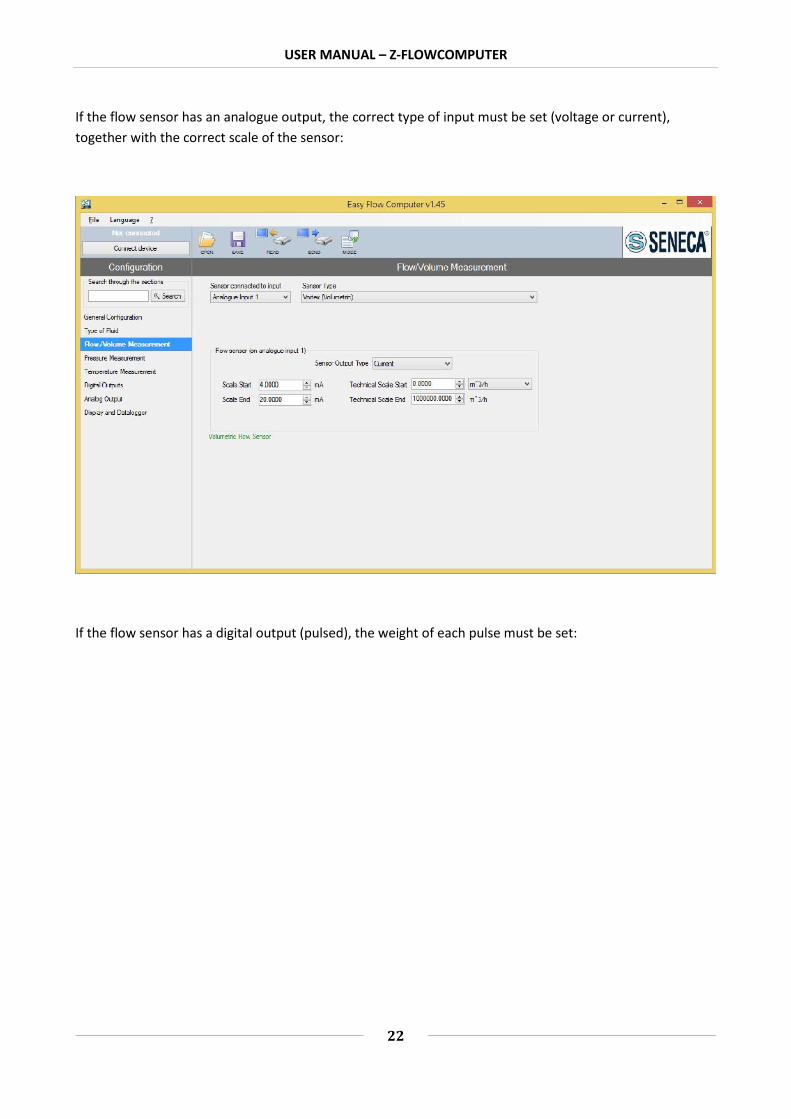
8.3. FLOW MEASUREMENT
In the menu select "Flow / Volume measurement", and then select the sensor used.
USER MANUAL – Z-FLOWCOMPUTER
22
If the flow sensor has an analogue output, the correct type of input must be set (voltage or current),together with the correct scale of the sensor:
If the flow sensor has a digital output (pulsed), the weight of each pulse must be set:

USER MANUAL – Z-FLOWCOMPUTER
23
With mass sensors, it is necessary to set the calibration point for pressure or temperature (recover thisinformation from the instrument configuration details).
The unit of measure of the volume measurement is connected to the type of sensor being used (Volumetricor Mass); the software will indicate any errors at the bottom of the screen.
The flow measurement is always associated to Analogue input 1 or Digital input 1.

USER MANUAL – Z-FLOWCOMPUTER
24
8.4. PRESSURE MEASUREMENT
The pressure measurement is required in case of overheated steam, while it can be used as an alternativeto temperature for saturated steam.
For water, an average pressure value can be entered.
In Z-FC, the pressure values are always considered absolute. For relative pressure meters, the set up of thenormalised atmospheric pressure (1.103 bar) is required.
Configure correctly the scale of the instrument and the value of the unit of measure used.
The pressure measurement is always associated to Analogue input 2.
ATTENTION!
For the purpose of internal calculations and displaying, all the pressure measurements are consideredabsolute.
8.5. TEMPERATURE MEASUREMENT
USER MANUAL – Z-FLOWCOMPUTER
25
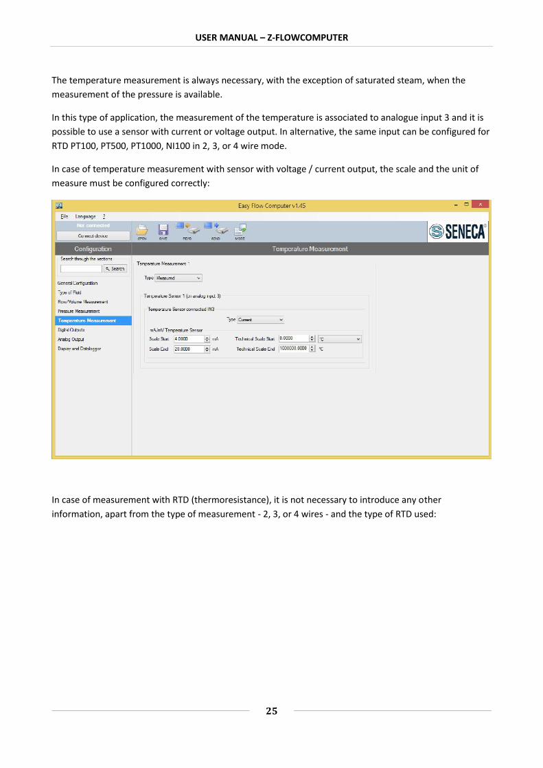
The temperature measurement is always necessary, with the exception of saturated steam, when themeasurement of the pressure is available.
In this type of application, the measurement of the temperature is associated to analogue input 3 and it ispossible to use a sensor with current or voltage output. In alternative, the same input can be configured forRTD PT100, PT500, PT1000, NI100 in 2, 3, or 4 wire mode.
In case of temperature measurement with sensor with voltage / current output, the scale and the unit ofmeasure must be configured correctly:
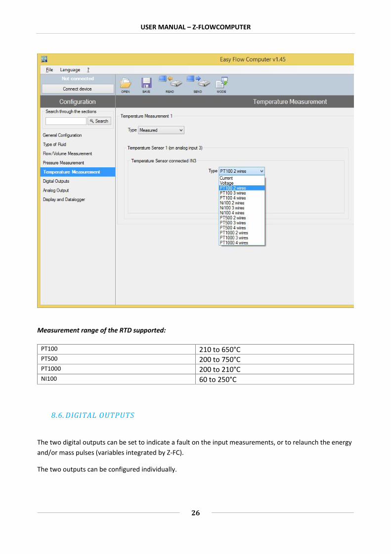
In case of measurement with RTD (thermoresistance), it is not necessary to introduce any otherinformation, apart from the type of measurement - 2, 3, or 4 wires - and the type of RTD used:
USER MANUAL – Z-FLOWCOMPUTER
26
Measurement range of the RTD supported:
PT100 210 to 650°CPT500 200 to 750°CPT1000 200 to 210°CNI100 60 to 250°C
8.6. DIGITAL OUTPUTS
The two digital outputs can be set to indicate a fault on the input measurements, or to relaunch the energyand/or mass pulses (variables integrated by Z-FC).
The two outputs can be configured individually.

USER MANUAL – Z-FLOWCOMPUTER
27
To detect the faults on the input measurements select alarm mode. Here, it is possible to set the validityrange of the measurements. It is enough for one measurement to fall outside the set range to trigger thealarm.
If the notification of the error of a particular measurement is not required, set the values outside the rangeof measurement of the sensor.
ATTENTION!
The alarm on the digital outputs does not stop the integration of the measurements.
To connect a variable to the pulse output, select pulse mode and enter every how many units the pulsemust be sent. The unit depends on the unit of measure selected for that variable in the Display andDatalogger section.
The duration of the pulse is T=100 ms, the minimum waiting time for the next pulse is Tmin=100 ms

USER MANUAL – Z-FLOWCOMPUTER
28
8.7. ANALOGUE OUTPUT
The analogue output can transmit to the other devices one of the variables available. Integrated oraccounted variables are not available on the analogue output (use the digital pulse output).
Select the type of output, current or voltage, the variable to transmit, and then set the scale:

USER MANUAL – Z-FLOWCOMPUTER
29
8.8. DISPLAY AND DATALOGGER
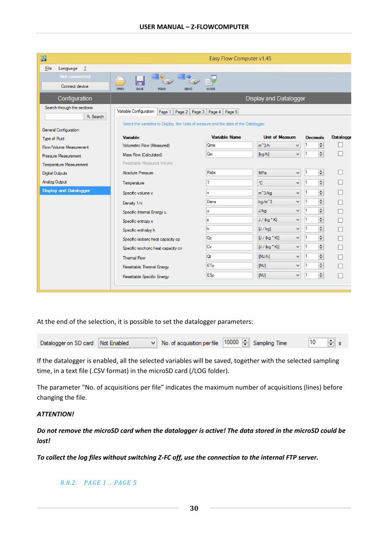
The Display and Datalogger section shows all the variables used by the specific application. It is possible toselect which ones to show on the display, with how many decimal numbers, and in which specific pages.
8.8.1. VARIABLE CONFIGURATION
In this section it is possible to select:
Which variables to show on the display Which name to give to the variables displayed The unit of measure of the variable How many decimal points must be shown in the variable If the variable must be logged
USER MANUAL – Z-FLOWCOMPUTER
30
At the end of the selection, it is possible to set the datalogger parameters:
If the datalogger is enabled, all the selected variables will be saved, together with the selected samplingtime, in a text file (.CSV format) in the microSD card (/LOG folder).
The parameter "No. of acquisitions per file" indicates the maximum number of acquisitions (lines) beforechanging the file.
ATTENTION!
Do not remove the microSD card when the datalogger is active! The data stored in the microSD could belost!
To collect the log files without switching Z-FC off, use the connection to the internal FTP server.
8.8.2. PAGE 1 . . PAGE 5
USER MANUAL – Z-FLOWCOMPUTER
31
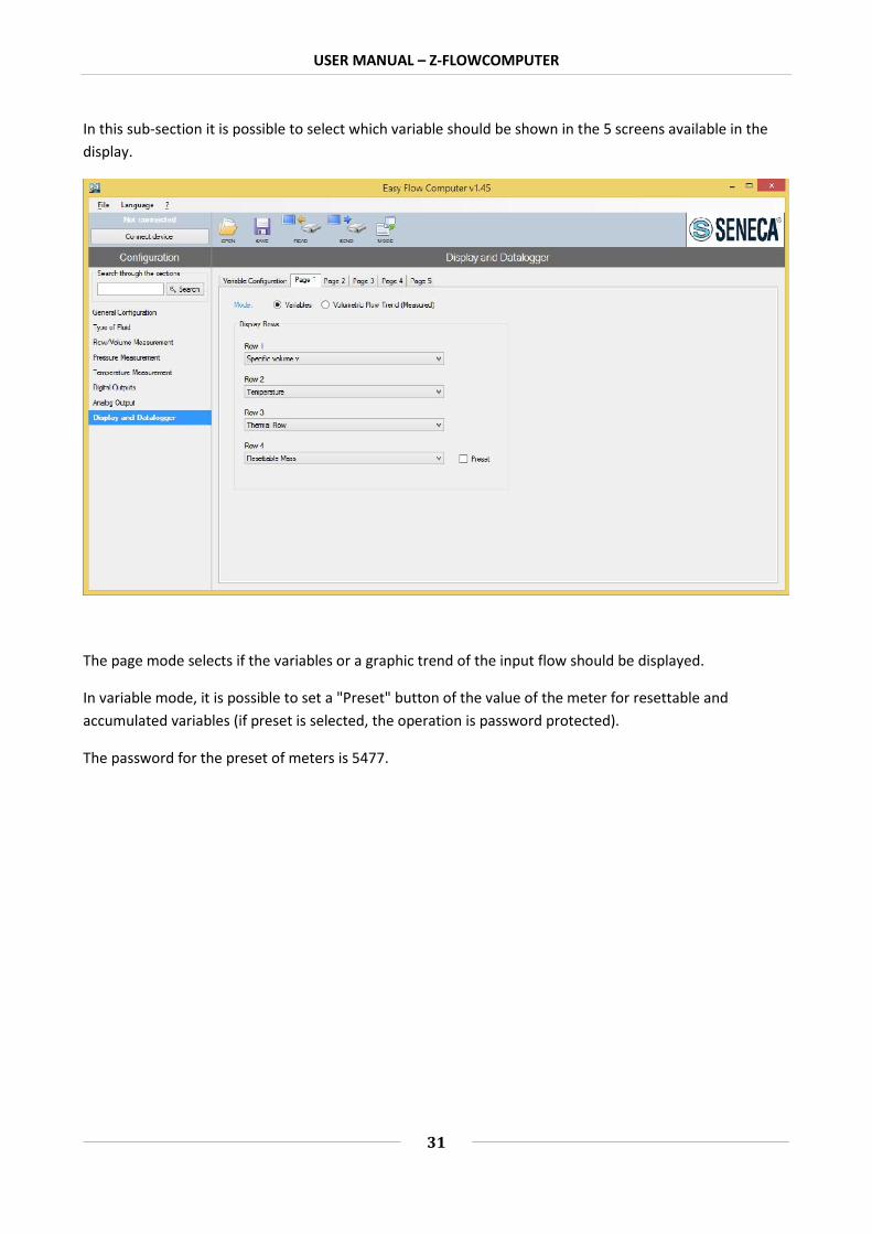
In this sub-section it is possible to select which variable should be shown in the 5 screens available in thedisplay.
The page mode selects if the variables or a graphic trend of the input flow should be displayed.
In variable mode, it is possible to set a "Preset" button of the value of the meter for resettable andaccumulated variables (if preset is selected, the operation is password protected).
The password for the preset of meters is 5477.

USER MANUAL – Z-FLOWCOMPUTER
32
8.9. CONNECTIONS
Meter connection diagram for the "Mass and steam calculation" application
USER MANUAL – Z-FLOWCOMPUTER
33
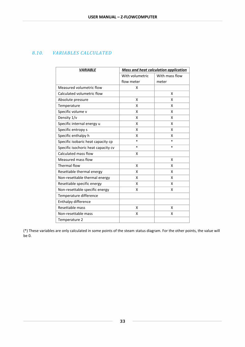
8.10. VARIABLES CALCULATED
VARIABLE Mass and heat calculation applicationWith volumetricflow meter
With mass flowmeter
Measured volumetric flow XCalculated volumetric flow XAbsolute pressure X XTemperature X XSpecific volume v X XDensity 1/v X XSpecific internal energy u X XSpecific entropy s X XSpecific enthalpy h X XSpecific isobaric heat capacity cp * *Specific isochoric heat capacity cv * *Calculated mass flow XMeasured mass flow XThermal flow X XResettable thermal energy X XNon-resettable thermal energy X XResettable specific energy X XNon-resettable specific energy X XTemperature differenceEnthalpy differenceResettable mass X XNon-resettable mass X XTemperature 2
(*) These variables are only calculated in some points of the steam status diagram. For the other points, the value willbe 0.

USER MANUAL – Z-FLOWCOMPUTER
34
9. APPLICATIONS WITH WATER AND STEAM: STEAM-WATER THERMALDIFFERENCE
The object of this application is to measure the power and the energy transferred to another system. In thedelivery piping is overheated steam, saturated steam, or water; in the return piping is the condensationwater. Z-FC calculates the transit power in the delivery piping and in the return piping, and the difference.The result is the exchanged thermal power.
For the measurement of overheated steam, the following are required: flow measurement, pressuremeasurement, delivery temperature measurement (T1) and return temperature measurement (T2).
For this application, it is necessary to select digital input 1 for the flow measurement. As a consequence,the flow meter must have a digital input.
For the measurement of saturated steam, the following are required: flow measurement, delivery pressureor temperature measurement (T1) (only one), and return temperature measurement (T2).
For the measurement of water, the following are required: flow measurement, delivery temperaturemeasurement (T1), return temperature measurement (T2).

USER MANUAL – Z-FLOWCOMPUTER
35
Required inputs
Type ofdelivery fluid
Flow (Q) CapacityDelivery
temperature (T1)Delivery pressure
(P)Return
temperature (T2)Overheated
steamYes (pulses only)
Yes Yes Yes
Saturatedsteam
Yes One of the two measurements Yes
Water Yes Yes Yes No
ATTENTION!
The T1 temperature and P pressure measurements must be taken near the flow meter.
The variables used by these applications are obtained starting from the IAPWS97 calculation standard (forfurther information refer to the chapter on calculation standards).
To correctly configure this application, refer to the next chapter. To continue, the latest version of the EasyFlowComputer software is required.
9.1. TYPE OF APPLICATION
In the "General Configuration" section select the type of application "Mass and Heat Calculation" or the“Difference” applications:

USER MANUAL – Z-FLOWCOMPUTER
36
9.2. TYPE OF FLUID
In the menu select the "Type of Fluid" section and then select the type of fluid.

USER MANUAL – Z-FLOWCOMPUTER
37
If "Saturated Steam" is selected, the associated pressure or temperature measurement must also beselected. For Overheated Steam / Water, both measurements are required.
9.3. FLOW MEASUREMENT
In the menu select "Flow / Volume measurement", and then select the sensor used.
If the flow sensor has an analogue output, the correct type of input must be set (voltage or current),together with the correct scale of the sensor:

USER MANUAL – Z-FLOWCOMPUTER
38
If the flow sensor has a digital output (pulsed), the weight of each pulse must be set:
With mass type sensors, the pressure/temperature calibration point is required (recover this informationfrom the instrument configuration details).

USER MANUAL – Z-FLOWCOMPUTER
39
The unit of measure of the pressure measurement is linked to the type of sensor being used (Volumetric orMass); the software will indicate any errors at the bottom of the screen.
The flow measurement is always associated to Analogue input 1 or Digital input 1.
9.4. PRESSURE MEASUREMENT
The pressure measurement is required in case of overheated steam, while it can be used as an alternativeto temperature for saturated steam.
For water, an average pressure value can be entered.
In Z-FC, the pressure values are always considered absolute. For relative pressure meters, the set up of thenormalized atmospheric pressure (1.103 bar) is required.
Correctly configure the scale of the instrument and the value of the unit of measure used.
The pressure measurement is always associated to Analogue input 2.
ATTENTION!
For the purpose of internal calculations and displaying, all the pressure measurements are consideredabsolute.

USER MANUAL – Z-FLOWCOMPUTER
40
9.5. DELIVERY (T1) AND RETURN (T2) TEMPERATURE MEASUREMENT
The T1 delivery temperature measurement is always necessary, with the exception of saturated steam,when the measurement of the pressure is available.
In this type of application, the measurement of the temperature is associated to analogue input 3 and it ispossible to use a sensor with current or voltage output. In alternative, the same input can be configured forRTD PT100, PT500, PT1000, NI100 in 2, 3, or 4 wire mode.
In case of temperature measurement with sensor with voltage / current output, the scale and the unit ofmeasure must be configured correctly:
In case of measurement with RTD (thermoresistance), it is not necessary to introduce any otherinformation, apart from the type of measurement - 2, 3, or 4 wires - and the type of RTD used:

USER MANUAL – Z-FLOWCOMPUTER
41

USER MANUAL – Z-FLOWCOMPUTER
42
Measurement range of the RTD supported:
PT100 210 to 650°CPT500 200 to 750°CPT1000 200 to 210°CNI100 60 to 250°C
The return temperature (T2) measurement must be taken from analogue input 1 or 2 (therefore, themeasurement can only be taken as voltage or current). Then configure the scale of the measurement.
ATTENTION!
Connect the temperature sensor to the unused analogue input. In case of error, the software will warn ifthe selected input is already being used.
9.6. DIGITAL OUTPUTS

USER MANUAL – Z-FLOWCOMPUTER
43
The two digital outputs can be set to indicate a fault on the input measurements, or to relaunch the energyand/or mass pulses (variables integrated by Z-FC).
The two outputs can be configured individually.
To detect the faults on the input measurements select alarm mode. Here, it is possible to set the validityrange of the measurements. It is enough for one measurement to fall outside the set range to trigger thealarm.
If the notification of the error of a particular measurement is not required, set the values outside the rangeof measurement of the sensor.
ATTENTION!
The alarm on the digital outputs does not stop the integration of the measurements.
To connect a variable to the pulse output, select pulse mode and enter every how many units the pulsemust be sent. The unit depends on the unit of measure selected for that variable in the Display andDatalogger section.
The duration of the pulse is T=100 ms, the minimum waiting time for the next pulse is Tmin=100 ms

USER MANUAL – Z-FLOWCOMPUTER
44
9.7. ANALOGUE OUTPUT
The analogue output can transmit to the other devices one of the variables available. Integrated oraccounted variables are not available on the analogue output (use the digital pulse output).
Select the type of output, current or voltage, the variable to transmit, and then set the scale:

USER MANUAL – Z-FLOWCOMPUTER
45
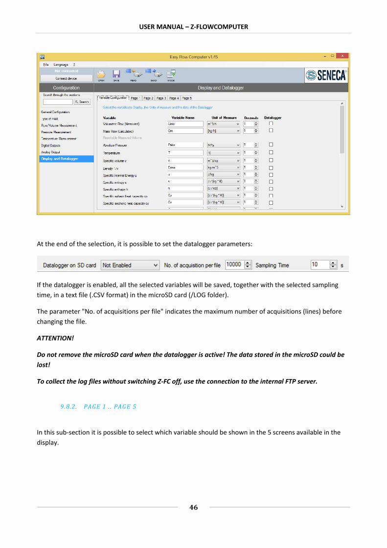
9.8. DISPLAY AND DATALOGGER
The Display and Datalogger section shows all the variables used by the specific application. It is possible toselect which ones must be shown on the display, with how many decimal numbers, and in which specificpages.
9.8.1. VARIABLE CONFIGURATION
In this section it is possible to select:
Which variables to show on the display Which name to give to the variables displayed The unit of measure of the variable How many decimal points must be shown in the variable If the variable must be logged
USER MANUAL – Z-FLOWCOMPUTER
46
At the end of the selection, it is possible to set the datalogger parameters:
If the datalogger is enabled, all the selected variables will be saved, together with the selected samplingtime, in a text file (.CSV format) in the microSD card (/LOG folder).
The parameter "No. of acquisitions per file" indicates the maximum number of acquisitions (lines) beforechanging the file.
ATTENTION!
Do not remove the microSD card when the datalogger is active! The data stored in the microSD could belost!
To collect the log files without switching Z-FC off, use the connection to the internal FTP server.
9.8.2. PAGE 1 . . PAGE 5
In this sub-section it is possible to select which variable should be shown in the 5 screens available in thedisplay.

USER MANUAL – Z-FLOWCOMPUTER
47
The page mode selects if the variables, or a graphic trend of the input flow, should be displayed.
In variable mode, it is possible to set a "Preset" button of the value of the meter for resettable andaccumulated variables (if preset is selected, the operation is password protected).
The password for the preset of meters is 5477.
9.9. CONNECTIONS
Typical connection diagram for the meters for the applications "Heating water-steam thermaldifference (calory count)" or "Cooling water-steam thermal difference (frigory count)":

USER MANUAL – Z-FLOWCOMPUTER
48

USER MANUAL – Z-FLOWCOMPUTER
49
9.10. VARIABLES CALCULATED
VARIABLE
Application
Calory count / Frigory countWith volumetric
flow meterWith mass flow
meterMeasured volumetric flow XCalculated volumetric flow XAbsolute pressure X XTemperature X XSpecific volume v X XDensity 1/v X XSpecific internal energy u X XSpecific entropy s X XSpecific enthalpy h X XSpecific isobaric heat capacity cp * *Specific isochoric heat capacity cv * *Calculated mass flow XMeasured mass flow XThermal flow X XResettable thermal energy X XNon-resettable thermal energy X XResettable specific energy X XNon-resettable specific energy X XTemperature difference X XEnthalpy difference X XResettable mass X XNon-resettable mass X XTemperature 2 X X
(*) These variables are only calculated in some points of the steam status diagram. For the other points, the value willbe 0.

USER MANUAL – Z-FLOWCOMPUTER
50
10. VOLUME CORRECTOR FOR IDEAL GASES
Available shortly.
11. VOLUME CORRECTOR FOR REAL GASES (RK, RKS EQUATION)
Available shortly.
11.1. EASY FLOW CONFIGURATIONS (RK, RKS EQUATIONS)
Available shortly.
12. VOLUME CORRECTOR FOR NATURAL GASES (SGERG88 ISO 12213-3CALCULATION)
Available shortly.
12.1. EASY FLOWCOMPUTER CONFIGURATION (SGERG88 ISO 12213 -3)
Available shortly.
13. VOLUME CORRECTOR FOR NATURAL GASES (AGA8 GROSS METHOD2 CALCULATION)
Available shortly.

USER MANUAL – Z-FLOWCOMPUTER
51
13.1. EASY FLOWCOMPUTER CONFIGURATION (AGA8 GROSS METHOD 2)
Available shortly.
14. VOLUME CORRECTOR FOR NATURAL GASES (AGA8 92-DC ISO12213-2 CALCULATION)
Available shortly.
14.1. EASY FLOWCOMPUTER CONFIGURATION (AGA8 92-DC ISO 12213-2)
Available shortly.

USER MANUAL – Z-FLOWCOMPUTER
52
15. USING THE Z-FLOWCOMPUTER DISPLAY
Using the display, it is possible to to view the parameters measured and calculated by Z-FC.
The display must be connected to the power supply and to Z-FC using and Ethernet cable. This is a touch-screen display. Therefore, by touching the relevant sections of the screen, it is possible to interact with theicons and the configurable fields.
For correct operation, the first three values of the IP address of the screen must be the same as those of Z-FC, while the last value will be different.
The factory configuration is as follows:
Display IP = 192.168.90.102
Z-FC IP = 192.168.90.101
If the display and Z-FC are not connected to the company Ethernet network, changing the above IPaddresses is not necessary.
After being switched on, the display appears as shown below.

USER MANUAL – Z-FLOWCOMPUTER
53
The touch sensitive icons are along the left and top edges, while at the centre are the variables selectedduring configuration. These variables are different for each page.
The following table shows the function of each icon
ICON Action when touchedReturn to page no. 1
Go to the configuration menu
Go to the previous page
Go to the next page
Prompt to enter the password for authorization to reset the meters.
The authorization code is 5477 and cannot be changed.
Go to the alarm log page
None; it indicates that Z-FC has been programmed using program 1 (waterand steam applications)
USER MANUAL – Z-FLOWCOMPUTER
54
None; it indicates that Z-FC has been programmed using program 2 (gasvolume correction applications)
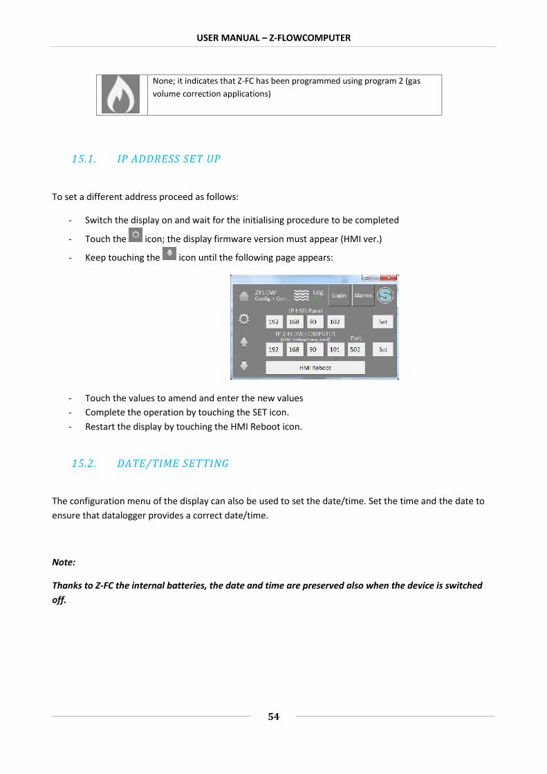
15.1. IP ADDRESS SET UP
To set a different address proceed as follows:
- Switch the display on and wait for the initialising procedure to be completed
- Touch the icon; the display firmware version must appear (HMI ver.)
- Keep touching the icon until the following page appears:
- Touch the values to amend and enter the new values- Complete the operation by touching the SET icon.- Restart the display by touching the HMI Reboot icon.
15.2. DATE/TIME SETTING
The configuration menu of the display can also be used to set the date/time. Set the time and the date toensure that datalogger provides a correct date/time.
Note:
Thanks to Z-FC the internal batteries, the date and time are preserved also when the device is switchedoff.

USER MANUAL – Z-FLOWCOMPUTER
55
16. The Web server
Z-FC has a built-in web server for advanced configuration purposes.
To access the web server using the Z-FLOWCOMPUTER factory IP address enter:
http://192.168.90.101/maintenance/index.html
where 192.168.90.101 is the factory address.
16.1. Z-FLOWCOMPUTER ADVANCED CONFIGURATION USING THE WEBSERVER
Using the web server, it is possible to complete some advanced configurations that are not availablethrough the Easy FlowComputer software
16.1.1. REAL TIME VIEW
In this section, it is possible to display in real time some parameters relating to Z-FLOWCOMPUTER and toanalogue inputs 1 and 2.

USER MANUAL – Z-FLOWCOMPUTER
56
16.1.2. SETUP
In this section, it is possible to configure the Z-FLOWCOMPUTER advanced parameters:

USER MANUAL – Z-FLOWCOMPUTER
57
DHCP
If active, it gives the possibility of obtaining an IP address from a DHCP server (typically the gateway/router)installed on the network.

USER MANUAL – Z-FLOWCOMPUTER
58
STATIC IP
The IP address when DHCP mode is not active.
STATIC IP MASK
The network mask used
STATIC GATEWAY ADDRESS
The gateway address.
DNS ADDRESS
The address of the DNS server to use.
ANALOG INPUTS SAMPLE TIME
The analogue input sampling time
INPUT TYPE ANALOG
Select if the input must be a voltage or current input.
SAMPLES TO AVERAGE ANALOG
This is the number of analogue samples used to calculate the average.
BEGIN SCALE ANALOG
This is the input scale start.
END SCALE ANALOG
This is the input scale end
BEGIN ENG. SCALE ANALOG
This is the engineering value connected to the analogue scale start.
END ENG. SCALE ANALOG
This is the engineering value connected to the analogue scale end.
WEB SERVER PORT
This is the port on which the web server service is active.
WEB SERVER AUTHENTICATION USER NAME
This is the user name for access to the web server.
WEB SERVER AUTHENTICATION USER PASSWORD

USER MANUAL – Z-FLOWCOMPUTER
59
This is the password for access to the web server.
SYNC CLOCK WITH TIME INTERNET
Enable or disable Internet date/time synchronisation.
SYNC CLOCK UPDATE EVERY
Select the Internet date/time synchronisation interval.
NTP SERVER
Set the Network Time Protocol server to obtain the date/time from the Internet.
DAYLIGHT SAVING TIME
Enable or disable the automatic switch to daylight saving time (European legal time).
GMT
Set the offset in relation to the Greenwich mean time (example: Italy +1).
DIGITAL INPUTS TYPE
Select if the digital input must be PNP or NPN type.
FILTER TIME DIGITAL INPUT
Set an ms filter on the digital inputs.
FAIL MODE DIGITAL OUTPUTS
Not used.
FAIL TIMEOUT DIGITAL OUTPUTS (s)
Not used.
DIGITAL OUTPUT STATE WHEN IN FAIL
Not used.
FACTORY DEFAULT
Return all the parameters to the factory values
16.1.3. LOCAL TIME SETUP
This section can be used to set the parameters regarding the local time and the day of the year.

USER MANUAL – Z-FLOWCOMPUTER
60
USER MANUAL – Z-FLOWCOMPUTER
61
17. THE MODBUS RTU AND THE MODBUS TCP-IP PROTOCOLS
Z-FLOWCOMPUTER supports Modbus RTU Slave and Modbus TCP-IP server protocols.
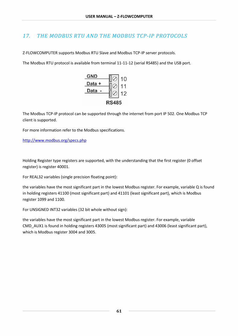
The Modbus RTU protocol is available from terminal 11-11-12 (serial RS485) and the USB port.
The Modbus TCP-IP protocol can be supported through the internet from port IP 502. One Modbus TCPclient is supported.
For more information refer to the Modbus specifications.
http://www.modbus.org/specs.php
Holding Register type registers are supported, with the understanding that the first register (0 offsetregister) is register 40001.
For REAL32 variables (single precision floating point):
the variables have the most significant part in the lowest Modbus register. For example, variable Q is foundin holding registers 41100 (most significant part) and 41101 (least significant part), which is Modbusregister 1099 and 1100.
For UNSIGNED INT32 variables (32 bit whole without sign):
the variables have the most significant part in the lowest Modbus register. For example, variableCMD_AUX1 is found in holding registers 43005 (most significant part) and 43006 (least significant part),which is Modbus register 3004 and 3005.

USER MANUAL – Z-FLOWCOMPUTER
62
17.1. TABLE OF THE MODBUS REGISTERS
VARIABLE
MODBUSREGISTER
(HOLDINGREGISTER)
NUMBER
REGISTERS FORMAT DESCRIPTION
TYPE
R = READING ONLY
R/W =READING/WRITING
Q 41100-41101 2 REAL 32 Volumetric flow R
Vmeas_par 41102-41103 2REAL 32 Volume measured
(resettable)R
Vmeas 41104-41105 2REAL 32 Volume measured (non
resettable)R
P 41106-41107 2 REAL 32 Absolute pressure R
T 41108-41109 2 REAL 32 Delivery temperature R
v 41110-41111 2 REAL 32 Specific volume R
rho 41112-41113 2 REAL 32 Density R
u 41114-41115 2 REAL 32 Specific Internal energy R
s 41116-41117 2 REAL 32 Specific entropy R
h 41118-41119 2 REAL 32 Specific enthalpy R
cp 41120-41121 2REAL 32 Specific isobaric heat
capacityR
cv 41122-41123 2REAL 32 Specific isochoric heat
capacityR
Qm 41124-41125 2 REAL 32 Mass flow R
QT 41126-41127 2 REAL 32 Thermal flow R
TE_par 41128-41129 2REAL 32 Thermal energy
(resettable)R
TE 41130-41131 2REAL 32 Thermal energy (non
resettable)R
SE_par 41132-41133 2REAL 32 Specific Energy
(resettable)R

USER MANUAL – Z-FLOWCOMPUTER
63
SE 41134-41135 2REAL 32 Specific energy (non
resettable)R
TD 41136-41137 2 REAL 32 Temperature difference R
Dh 41138-41139 2 REAL 32 Enthalpy difference R
Vref_par 41140-41141 2REAL 32 Corrected volume
(resettable)R
Vref 41142-41143 2REAL 32 Corrected volume (non
resettable)R
M_par 41144-41145 2 REAL 32 Mass (resettable) R
M 41146-41147 2 REAL 32 Mass (non resettable) R
T2 41148-41149 2 REAL 32 Temperature 2 R
Qref 41150-41151 2REAL 32 Corrected volumetric
flowR
CMD_REG 42000 1UNSIGNED INT
16 Command registerR/W
CMD_AUX1 43005-43006 2UNSIGNED INT
32Value to load - whole
partR/W
CMD_AUX2 43007-43008 2REAL 32 Value to load - fractional
partR/W

USER MANUAL – Z-FLOWCOMPUTER
64
17.2. FORWARDING OF COMMANDS USING THE MODBUS PROTOCOL
Z-FC commands can be sent using the CMD_REG register. Below is the list of supported commands:
COMMAND
(hexadecimal value)
DESCRIPTION
0xBEC1 Loads the value of theCMD_AUX1 register as a
whole and that ofCMD_AUX2 as fraction of
the resettable volumevariable.
0xBEC2 Loads the value of theCMD_AUX1 register as a
whole and that ofCMD_AUX2 as fraction of
the non-resettable volumevariable.
0xBEC3 Loads the value of theCMD_AUX1 register as a
whole and that ofCMD_AUX2 as fraction of
the resettable thermalenergy variable.
0xBEC4 Loads the value of theCMD_AUX1 register as a
whole and that ofCMD_AUX2 as fraction of
the non-resettablethermal energy variable.
0xBEC5 Loads the value of theCMD_AUX1 register as a
whole and that ofCMD_AUX2 as fraction of
the resettable specificenergy variable.
0xBEC6 Loads the value of theCMD_AUX1 register as a
whole and that ofCMD_AUX2 as fraction of

USER MANUAL – Z-FLOWCOMPUTER
65
the non-resettable specificenergy variable.
0xBEC7 Loads the value of theCMD_AUX1 register as a
whole and that ofCMD_AUX2 as fraction ofthe resettable corrected
volume variable.
0xBEC8 Loads the value of theCMD_AUX1 register as a
whole and that ofCMD_AUX2 as fraction of
the non-resettablecorrected volume variable.
0xBEC9 Loads the value of theCMD_AUX1 register as a
whole and that ofCMD_AUX2 as fraction ofthe resettable mass flow
variable.
0xBECA Loads the value of theCMD_AUX1 register as a
whole and that ofCMD_AUX2 as fraction ofthe non-resettable mass
flow variable.
0xABC0 Stops the datalogger(must be enabled).
0xABC1 Starts the datalogger(must be enabled).

USER MANUAL – Z-FLOWCOMPUTER
66
18. Z-FC AND DISPLAY FIRMWARE AND SOFTWARE UPDATE
The Z-FC firmware can be updated using the internal ftp server or the microSD card.
18.1. Z-FC firmware update
18.1.1. Updating the firmware from the FTP server
To update the Z-FC firmware from the FTP server, it is necessary to insert a microSD card formatted using aFAT16 or FAT32 file system.
Connect to the Z-FC FTP server and copy the "zflow.bin" file with the new firmware in the main folder (root)of the FTP server.
Once the transfer of the file has been completed, Z-FC will turn on the 4 red LEDs and will start to updatethe firmware on the internal flash (duration 30 seconds).
At the end Z-FC will restart with the new software.
ATTENTION!
Do not switch off Z-FlowComputer before completing the firmware update procedure!
18.1.2. Firmware update using the microSD card
To update the firmware using the microSD card follow this procedure:
Switch off Z-FC Copy the "zflow.bin" file in the main folder (root) of the microSD (use a PC with a SD card reader) Insert the microSD card in Z-FC Switch on Z-FC Z-FC will turn on the 4 red LEDs and will start to update the software on the internal flash (duration
about 30 seconds). At the end Z-FC will restart with the new software. The "zflow.bin" file will be deleted automatically from the microSD card.
ATTENTION!
Do not switch off Z-FlowComputer before completing the firmware update procedure!
18.2. Display software update

USER MANUAL – Z-FLOWCOMPUTER
67
It is possible to update the Z-FC display software using the following procedure. For this procedure, a USBflash drive is required.
Copy the mt8000ie folder and its content in the main folder of the USB flash drive:
Switch the display on and insert the USB flash drive in the USB port of the display. A menu will appear on the display. Select "Download". Enter password 111111 and confirm. Select "USB Disk" and "Disk_a_1" and press OK. At the end of the operation the display returns to normal operation. Remove the USB flash drive from the display
19. CONNECTION TO THE Z-FLOWCOMPUTER FTP SERVER
Z-FC has a FTP server. To access it, Seneca recommends the use of Filezilla Client.
Download the Filezilla Client from:
https://filezilla-project.org/download.php?show_all=1
Launch the installation and configure a new site:

USER MANUAL – Z-FLOWCOMPUTER
68
Enter the Z-FC IP (default 192.168.90.101) and the access credentials (default User: admin;Password:admin):
In the Transfer Settings section limit the maximum number of connections to 1:
Now in the main filezilla menu increase the maximum timeout to 999 seconds: Edit -> Settings

USER MANUAL – Z-FLOWCOMPUTER
69

USER MANUAL – Z-FLOWCOMPUTER
70
20. CALCULATION STANDARDS USED
20.1. IAPWS-IF 97 CALCULATION STANDARD
The applications of program 1 are based on the calculation standard IAPWS Industrial Formulation 1997.
The implementation used on Z-FC is valid for the following pressure and temperature ranges:
Temperature >= 0°C and <= 800°C
Pressure >= 0 MPa and <= 100 MPa
Within this range, 4 regions are identified, each characterised by different equations.
20.1.1. REGIONS IDENTIFIED BY IAPWS-IF 97
Region 1 represents water in liquid state.
Region 2 represents steam state.
Region 2 identifies the thermodynamic state near the critical point.
Region 4 is represented by the saturation curve (saturated fluid).
USER MANUAL – Z-FLOWCOMPUTER
71
Regions 1 and 2 are each represented by a fundamental equation for the the Gibbs specific free energyg(p,T).
Region 3 is represented by a fundamental equation for the Helmholtz specific free energy f(ρ,T) (where p isdensity).
Region 4 is represented by a Ps(T) equation or by a Ts(P) equation.
The thermodynamic quantity calculated by Z-FC depends on the region in which they are calculated. Inparticular:
Thermodynamic quantities calculated in Region 1 (water in liquid state)
Specific volume (v)Density (1/v)Specific internal energy (u)Specific entropy (s)Specific enthalpy (h)Specific isobaric heat capacity (cp)
Thermodynamic quantities calculated in Region 2 (steam)
Specific volume (v)Density (1/v)Specific internal energy (u)Specific entropy (s)Specific enthalpy (h)Specific isobaric heat capacity (cp)
Thermodynamic quantities calculated in Region 3 (thermodynamic status near the critical point)
Density (1/v)Specific internal energy (u)Specific entropy (s)Specific enthalpy (h)Specific isochoric heat capacity (cv)
Thermodynamic quantities calculated in Region 4 (saturation curve)
Specific volume (v)Density (1/v)Specific internal energy (u)Specific entropy (s)Specific enthalpy (h)Specific isobaric heat capacity (cp)

USER MANUAL – Z-FLOWCOMPUTER
72
20.2. IDEAL GAS EQUATION
Available soon.
20.3. RK, RKS EQUATIONS
Available soon.
20.4. CALCULATION STANDARD - SGERG88 (ISO 12213-3)
Available soon.
20.5. CALCULATION STANDARD - AGA8 GROSS METHOD 2
Available soon.
20.6. CALCULATION STANDARD - AGA8 92-DC (ISO 12213-2)
Available soon.