USER MANUAL - Qoltec · USER MANUAL MODEL: 53920 ... 1KVA With a 1A internal charger and 3 build-in...
28
UNINTERRUPTIBLE POWER SUPPLY (UPS) USER MANUAL MODEL: 53920 | 53921 | 53922 www.qoltec.com EN
Transcript of USER MANUAL - Qoltec · USER MANUAL MODEL: 53920 ... 1KVA With a 1A internal charger and 3 build-in...

UNINTERRUPTIBLE POWER SUPPLY (UPS)
USER MANUAL
MODEL: 53920 | 53921 | 53922
www.qoltec.com
EN

1
Content
1. Introduction ..................................................................................................................................................................................................................... 2
1.1 Description of Commonly Used Symbols .............................................................................................................................................................. 2
1.2 Safety Instructions .................................................................................................................................................................................................... 2
2. Product Description......................................................................................................................................................................................................... 2
2.1 System Type and Configuration .............................................................................................................................................................................. 3
2.2 The Appearance of the UPS ..................................................................................................................................................................................... 3
2.3 Operating Principle ................................................................................................................................................................................................... 3
3. Installation ........................................................................................................................................................................................................................ 4
3.1 Unpacking Inspection ............................................................................................................................................................................................... 4
3.2 Installation Notes...................................................................................................................................................................................................... 4
3.3 Cable Connection ..................................................................................................................................................................................................... 4
3.3.1 Connecting Input and Output Cables .................................................................................................................................................................. 4
3.3.2 Connecting Communication Cable ...................................................................................................................................................................... 5
3.3.3 Description of communication interface ............................................................................................................................................................ 5
4. Operation (LCD model) ................................................................................................................................................................................................... 7
4.1 Operation Display Panel .......................................................................................................................................................................................... 7
4.2 Operation Mode ....................................................................................................................................................................................................... 7
4.2.1 Normal mode ......................................................................................................................................................................................................... 7
4.2.2 Battery Mode ......................................................................................................................................................................................................... 8
4.2.3 Bypass Mode .......................................................................................................................................................................................................... 8
4.2.4 LCD indication of UPS alarm status and faults ................................................................................................................................................... 9
4.3 Operating Instructions ........................................................................................................................................................................................... 10
4.3.1 UPS ON/OFF Operation ....................................................................................................................................................................................... 10
4.3.2 Conducting Battery self-diagnosis ..................................................................................................................................................................... 10
4.3.3 Setting the output voltage and frequency ........................................................................................................................................................ 10
5. Maintenance .................................................................................................................................................................................................................. 11
5.1 Battery Maintenance .............................................................................................................................................................................................. 11
5.2 Checking UPS function ........................................................................................................................................................................................... 11
6. Troubleshooting ............................................................................................................................................................................................................. 11
7. Specifications ................................................................................................................................................................................................................. 13
7.1 Electrical .................................................................................................................................................................................................................. 13
7.2 Environmental ......................................................................................................................................................................................................... 13
7.4 Safety ....................................................................................................................................................................................................................... 13
2
1. Introduction
1.1 Description of Commonly Used Symbols
Some or all of the following symbols may be used in this manual and may appear in your application process. Therefore, all users should read
this manual carefully and thoroughly.
1.2 Safety Instructions
1. Read this manual carefully and thoroughly before operation the UPS and save this manual properly for future reference.
2. Do not tear up or shatter the alarm table on the UPS and pay attention to it.
3. Please do not overload the UPS.
4. The UPS contains large capacity batteries. The case of the UPS must not be opened by untrained personnel. Otherwise, it may cause electric
shock.
5. Do not short the positive and negative electrodes of battery. Otherwise, it may cause electric shock or fire.
6. Do not plunge or insert any objects into the air vents and other inlets.
7. Do not store or use the device in the following environment:
Where there is inflammable gas, corrosive agents or heavy dust.
Where the temperature is very high or low (above 40℃ or below 0℃) or the humidity is very high(more than 90%).
Under direct sunlight or close to heating facilities.
Place of strong vibrations.
8. In the event of fire occurring in the vicinity, please use dry powder fire extinguishers. The use of liquid fire extinguishing agents may cause
electric shock.
BATTERY DISPOSAL:
This product contains a lithium polymer battery. Dispose battery with local
law to protect the environment. To obtain more detailed information about
the recycling of this product, please contact your local authority, household
waste disposal service or the shop where you purchased the product.
2. Product Description
The UPS is an on-line uninterruptible power supply device incorporating double-converter technology with single-phase input and single-
phase output. It offers the high quality power supply with the greatest degree of availability and reliability. The UPS is compact and convenient
for users.
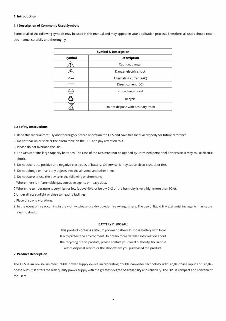
Symbol & Description
Symbol Description
Caution, danger
Danger electric shock
Alternating current (AC)
Direct current (DC)
Protective ground
Recycle
Do not dispose with ordinary trash
3
2.1 System Type and Configuration
There are two types of UPS according to the battery configuration: standard type and long backup time type, each available in the following
ratings: 1KVA, 2KVA and 3KVA UPS.
Type Model Remark
Standar
d
1KVA With a 1A internal charger and 3 build-in batteries of 12V/ 7AH.
2KVA With a 1A internal charger and 6 (or 8) build-in batteries of 12V/
7AH.
3KVA With a 1A internal charger and 8 (or 6) build-in batteries of 12V/
7AH.
Table 2-1 UPS types and configurations
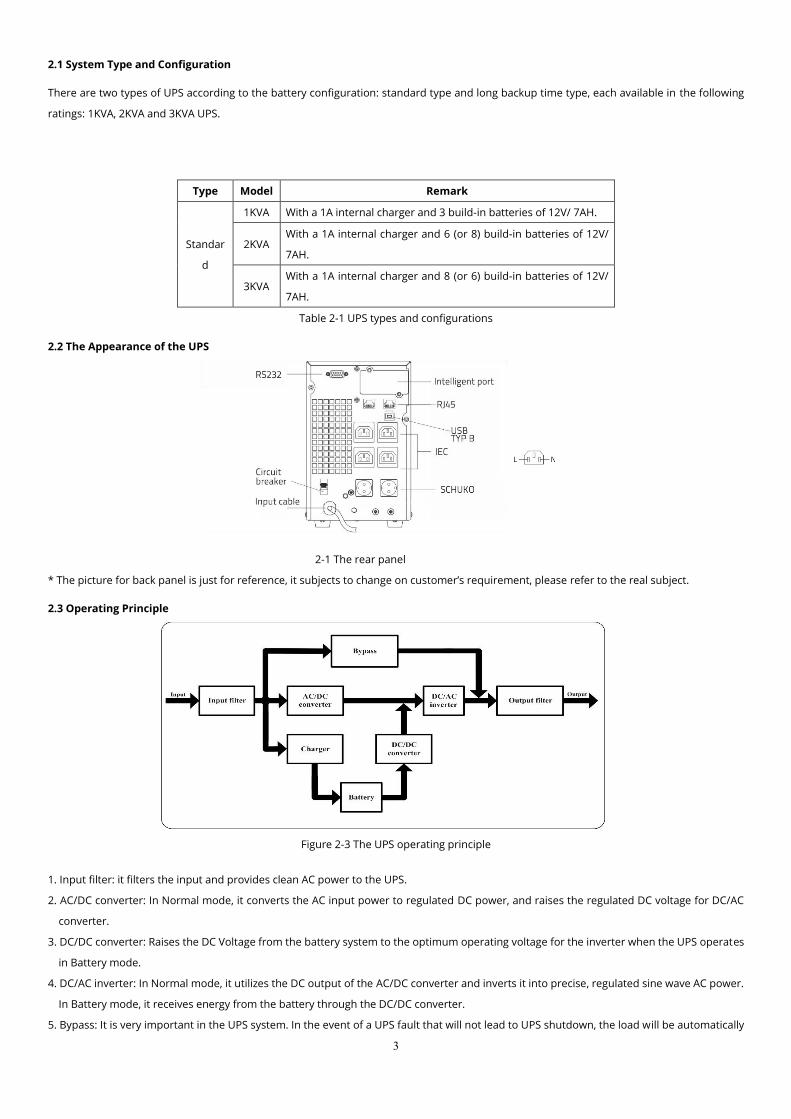
2.2 The Appearance of the UPS
2-1 The rear panel
* The picture for back panel is just for reference, it subjects to change on customer’s requirement, please refer to the real subject.
2.3 Operating Principle
Figure 2-3 The UPS operating principle
1. Input filter: it filters the input and provides clean AC power to the UPS.
2. AC/DC converter: In Normal mode, it converts the AC input power to regulated DC power, and raises the regulated DC voltage for DC/AC
converter.
3. DC/DC converter: Raises the DC Voltage from the battery system to the optimum operating voltage for the inverter when the UPS operates
in Battery mode.
4. DC/AC inverter: In Normal mode, it utilizes the DC output of the AC/DC converter and inverts it into precise, regulated sine wave AC power.
In Battery mode, it receives energy from the battery through the DC/DC converter.
5. Bypass: It is very important in the UPS system. In the event of a UPS fault that will not lead to UPS shutdown, the load will be automatically
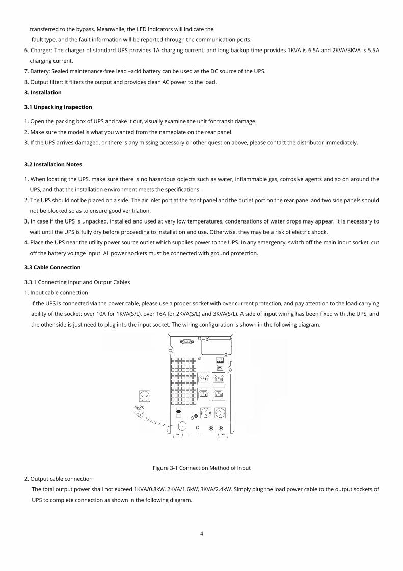
4
transferred to the bypass. Meanwhile, the LED indicators will indicate the
fault type, and the fault information will be reported through the communication ports.
6. Charger: The charger of standard UPS provides 1A charging current; and long backup time provides 1KVA is 6.5A and 2KVA/3KVA is 5.5A
charging current.
7. Battery: Sealed maintenance-free lead –acid battery can be used as the DC source of the UPS.
8. Output filter: It filters the output and provides clean AC power to the load.
3. Installation
3.1 Unpacking Inspection
1. Open the packing box of UPS and take it out, visually examine the unit for transit damage.
2. Make sure the model is what you wanted from the nameplate on the rear panel.
3. If the UPS arrives damaged, or there is any missing accessory or other question above, please contact the distributor immediately.
3.2 Installation Notes
1. When locating the UPS, make sure there is no hazardous objects such as water, inflammable gas, corrosive agents and so on around the
UPS, and that the installation environment meets the specifications.
2. The UPS should not be placed on a side. The air inlet port at the front panel and the outlet port on the rear panel and two side panels should
not be blocked so as to ensure good ventilation.
3. In case if the UPS is unpacked, installed and used at very low temperatures, condensations of water drops may appear. It is necessary to
wait until the UPS is fully dry before proceeding to installation and use. Otherwise, they may be a risk of electric shock.
4. Place the UPS near the utility power source outlet which supplies power to the UPS. In any emergency, switch off the main input socket, cut
off the battery voltage input. All power sockets must be connected with ground protection.
3.3 Cable Connection
3.3.1 Connecting Input and Output Cables
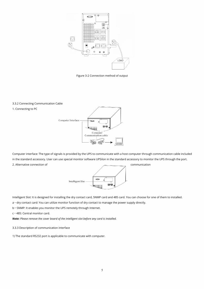
1. Input cable connection
If the UPS is connected via the power cable, please use a proper socket with over current protection, and pay attention to the load-carrying
ability of the socket: over 10A for 1KVA(S/L), over 16A for 2KVA(S/L) and 3KVA(S/L). A side of input wiring has been fixed with the UPS, and
the other side is just need to plug into the input socket. The wiring configuration is shown in the following diagram.
Figure 3-1 Connection Method of Input
2. Output cable connection
The total output power shall not exceed 1KVA/0.8kW, 2KVA/1.6kW, 3KVA/2.4kW. Simply plug the load power cable to the output sockets of
UPS to complete connection as shown in the following diagram.
5
Figure 3-2 Connection method of output
3.3.2 Connecting Communication Cable
1. Connecting to PC
Computer interface: The type of signals is provided by the UPS to communicate with a host computer through communication cable included
in the standard accessory. User can use special monitor software UPSilon in the standard accessory to monitor the UPS through the port.
2. Alternative connection of communication
Intelligent Slot: It is designed for installing the dry contact card, SNMP card and 485 card. You can choose for one of them to installed.
a-dry contact card: You can utilize monitor function of dry contact to manage the power supply directly.
b-SNMP: It enables you monitor the UPS remotely through Internet.
c-485: Central monitor card.
Note: Please remove the cover board of the intelligent slot before any card is installed.
3.3.3 Description of communication interface
1) The standard RS232 port is applicable to communicate with computer.

6
Description and pin assignment of RS232
Baud rate: 2400bps
Data bit: 8 bit
Stop bit: 1bit
Parity bit: No
DB-9 pin assignment:
RS232 Interface
Pin
number
Function
description I/O
3 Rxd Input
2 Txd Output
5 GND Ground
2) USB Type B:
Male Female
USB pin definition:
Note: When RS232 and USB Type B are provided, only one of them will be chosen and RS232 is preferred.
3) User enables to monitor and manage the UPS through installed the AS400 card (optional).
PIN1: UPS failure (normally open, active close)
PIN2: Summary alarm
PIN3: Ground
PIN4: Remote shutdown
PIN5: Common
PIN6: Bypass active (relay close)
PIN7: Low battery
PIN8: UPS on (relay close)
PIN9: Utility Power failure (normally open, active close)
AS400 Interface
Pin Function Color Note
1 V Bus Red 5V
2 Data - White Data -
3 Data + Green Data +
4 GND Black Ground

7
4. Operation (LCD model)
4.1 Operation Display Panel
1. ON button:
Pressing the ON button more than 1 second (buzzer beeps once), the UPS system is turned on.
2. OFF button:
By pressing this button more than 1 second (buzzer beeps once) turns off the UPS system whenever the UPS run under the normal
mode/battery mode.
3. Function button
The Function button provides the following functions:
a) Battery self- diagnosis: When the UPS ran in normal mode, pressing this button more than 2 seconds (buzzer beeps twice) can start the
battery self-diagnosis.
b) Silence function in battery/bypass mode
In battery/bypass mode, when the buzzer beeps, pressing and holding the function button for more than 2 seconds (buzzer beeps two
times) can silence the buzzer. Press the button for more than 2 seconds (buzzer beeps twice) again to resume the alarm function.
c) LCD display screen switch
Pressing the function button for more than 1 seconds and less than 2 seconds (buzzer beeps once) to switch LCD display screen.
4. LED indicators, Bypass indicator, utility power indicator, Inverter indicator, Battery indicator. The definition of each indicator is the same as
LED panel (refer to table 4-1).
4.2 Operation Mode
UPS Operation Mode contains normal mode, battery mode and bypass mode. Under the three modes, the page showing output voltage and
output frequency is the main display page. If users need more information about UPS, Pressing the function button can initiate display screen
switch. If the current page is not the main page, UPS will automatically switch back the main page after 30 seconds. In order to extend the LCD
usage life, the backlight will turn off after 1 minute without any switch operation. At this point, Users just need to touch any button briefly to
turn on the backlight.
4.2.1 Normal mode
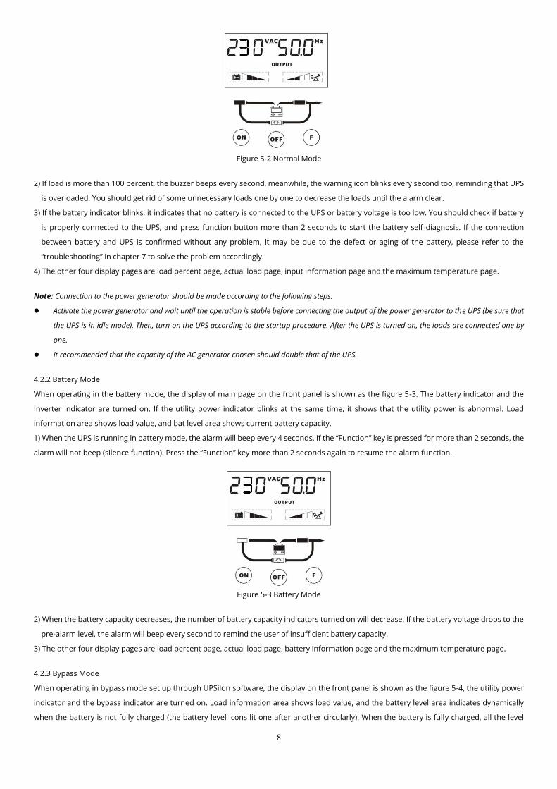
When operating in the normal mode, the display of main page on the front panel is shown as the figure 5-2. The utility power indicator and
the Inverter indicator are turned on. Load information area shows load value, and the battery level area indicates dynamically when the battery
is not fully charged (the battery level icons lit one after another circularly). When the battery is fully charged, all the level icons are turned on.
1) If the utility power indicator blinks, it indicates that there are problems with reversed polarity (L, N) of site wiring or disconnect with ground.
UPS is still working in normal mode. If the battery indicator is turned on at the same time, it shows that the voltage or frequency of the utility
power is out of the normal input range of the UPS. The UPS works in battery mode.
8
Figure 5-2 Normal Mode
2) If load is more than 100 percent, the buzzer beeps every second, meanwhile, the warning icon blinks every second too, reminding that UPS
is overloaded. You should get rid of some unnecessary loads one by one to decrease the loads until the alarm clear.
3) If the battery indicator blinks, it indicates that no battery is connected to the UPS or battery voltage is too low. You should check if battery
is properly connected to the UPS, and press function button more than 2 seconds to start the battery self-diagnosis. If the connection
between battery and UPS is confirmed without any problem, it may be due to the defect or aging of the battery, please refer to the
“troubleshooting” in chapter 7 to solve the problem accordingly.
4) The other four display pages are load percent page, actual load page, input information page and the maximum temperature page.
Note: Connection to the power generator should be made according to the following steps:
Activate the power generator and wait until the operation is stable before connecting the output of the power generator to the UPS (be sure that
the UPS is in idle mode). Then, turn on the UPS according to the startup procedure. After the UPS is turned on, the loads are connected one by
one.
It recommended that the capacity of the AC generator chosen should double that of the UPS.
4.2.2 Battery Mode
When operating in the battery mode, the display of main page on the front panel is shown as the figure 5-3. The battery indicator and the
Inverter indicator are turned on. If the utility power indicator blinks at the same time, it shows that the utility power is abnormal. Load
information area shows load value, and bat level area shows current battery capacity.
1) When the UPS is running in battery mode, the alarm will beep every 4 seconds. If the “Function” key is pressed for more than 2 seconds, the
alarm will not beep (silence function). Press the “Function” key more than 2 seconds again to resume the alarm function.
Figure 5-3 Battery Mode
2) When the battery capacity decreases, the number of battery capacity indicators turned on will decrease. If the battery voltage drops to the
pre-alarm level, the alarm will beep every second to remind the user of insufficient battery capacity.
3) The other four display pages are load percent page, actual load page, battery information page and the maximum temperature page.
4.2.3 Bypass Mode
When operating in bypass mode set up through UPSilon software, the display on the front panel is shown as the figure 5-4, the utility power
indicator and the bypass indicator are turned on. Load information area shows load value, and the battery level area indicates dynamically
when the battery is not fully charged (the battery level icons lit one after another circularly). When the battery is fully charged, all the level

9
icons are turned on.
1) When operating in bypass mode, the UPS beeps every 2 minutes. If the “Function” key is pressed for more than 2 seconds, the alarm will
not beep (silence function). Press the “Function” key more than 2 seconds again to resume the alarm function.
2) If the utility power indicator blinks, it shows that the voltage or frequency of the utility power is out of the input range of the UPS or there
are problems with reversed polarity (L/N) of site wiring or disconnect to the ground for protection.
3) The other four display pages are load percent page, actual load page, input information page and the maximum temperature page.
Notes: When operating in bypass mode, the backup function of the UPS is not available and the power used by the load is directly from the utility
power via internal EMI filter.
Figure 5-4 Bypass Mode
4.2.4 LCD indication of UPS alarm status and faults
In the event of an UPS fault, UPS enters fault operation mode, at this point, the fault icon turns on consistently, the buzzer beeps continuously
and the data information area shows current fault code (refer to table 7-2), the display on the front panel is shown as the figure 5-5, users can
switch to output page by pressing function button.
Figure 5-5 Fault display
When a warning occurred, the fault icon blinks every second, and users can switch to the alarm display page shown as the figure 5-6 to check
the warning code.
Figure 5-6 Alarm display
10
4.3 Operating Instructions
4.3.1 UPS ON/OFF Operation
Note: The battery is fully charged before delivery. However, storage and transportation will inevitably cause some charge loss. Therefore, it is advisable
to charge the battery for 10 hours before using it, so as to ensure adequate battery capacity.
1. Turning on the UPS
The operation of turning on the UPS contains: turning on with utility power and turning on without utility power.
1) Turning on with utility power:
Connect the mains input to the UPS, press the ON button more than one second, UPS starts to turn on. At this point, the LCD begins to
conduct self-diagnosis (all the LCD indicators are turn on about 4 seconds). A few seconds later, the UPS will begin to operate in Normal
mode; meanwhile, the utility power indicator, inverter indicators will turn on. If the utility power is abnormal, the UPS will work in battery
mode.
2) Turning on without utility power:
With no mains input feed to the UPS, press the ON button more than one second, UPS starts to turn on. At this point, the LCD begins to
conduct self-diagnosis (all the LCD indicators are turn on about 4 seconds). A few seconds later, the battery indicator, inverter indicators
will be turn on to indicate that the UPS is working in battery mode.
2. Powering down the UPS
The operation of powering down the UPS contains: turning off UPS in normal mode, turning off UPS in battery mode.
1) Completely power down the UPS from Normal mode
Hold and press the OFF button persistently for more than 1 second to power
off the UPS. If it bas been set up to work in bypass mode by software, the bypass indicator will be turned on to indicate that the UPS is
working in bypass mode. In order to cut off the output from the UPS, simply cut off the utility power supply. LCD begins to conduct self-
diagnosis (all the LCD indicators are turned on about 4 seconds), a few seconds later, not any display is shown on the front panel and no
output is available from the UPS outlets, system completely power down.
2) Completely power down the UPS from Battery mode
Press the “OFF” button persistently for more than 1 second to power off the UPS. When being powered off, the LCD will start self-diagnosis
(all the LCD indicators are turn on about 4 seconds), a few seconds later, not any display is shown on the front panel and no voltage output
is available from the UPS outlets, system completely power down.
4.3.2 Conducting Battery self-diagnosis
In UPS operation, users can manually initiate battery self-diagnosis to check the battery conditions. There are two methods to initiate the
battery self-diagnosis:
1. Through the function button
In normal mode, press and hold the function for more than 2 seconds until the buzzer beeps twice. At this point the indicators (LED7~10)
will blink cyclically, indicating the UPS has worked in battery mode and the battery self-diagnosis has started. The battery self-diagnosis will
last for 10 seconds default. In the event of a battery fault during battery self-diagnosis, the UPS will transfer to normal mode automatically.
2. Through the monitor software
Users can also initiate battery self-diagnosis through the background monitoring software
4.3.3 Setting the output voltage and frequency
1) Connect the mains input to the UPS, and make the UPS works in standby mode or bypass mode.
2) Press the 'F' and 'OFF' button more than one second, then release, the buzzer will beep once, the "OUTPUT" is flashing, which means all of
bottom are used for UPS setting, at this point, if the "VAC" is flashing, it means the output voltage is set to enable; if the "Hz" is flashing, it
means the frequency is set to enable, the LCD screen indicator represents current output voltage and frequency setting value.
3) If you need to set the voltage, check if the voltage setting is enabled ("VAC" is flashing), If not, press the 'F' more than one second, then
release, the output setting is enabled, at this point you can start to set output voltage.
11
4) Release the 'OFF' key after you press it more than one second, LCD display the selected output voltage in turn.
5) Repeat the fourth step until the LCD indicator meets the required voltage.
6) Press 'ON' key about one second, the output voltage setting completed.
7) The frequency setting is the same as the voltage setting, but before the setting, please confirm the frequency setting is enabled, if not, press
'F' key about one second in order to switch to the frequency setting screen ("Hz" is flashing).
8) When done, Press the 'F' and 'OFF' button more than one second, then release, the buzzer will beep once, exit the setting mode.
In the setting process, if no key is detected within twenty second, the UPS exits the setting screen automatically.
5. Maintenance
5.1 Battery Maintenance
The battery is key component of the UPS. The battery life depends on the ambient temperature, charging and discharging times. High ambient
temperature and deep discharging will shorten the battery life.
1. Sealed maintenance-free lead –acid battery be used in the standard. When being connected to the utility power whether the UPS has been
turned on or not, the UPS keeps charging the battery and also offers the protective function of charging and discharging.
2. Keep the ambient temperature between 15℃ and 25℃.
3. If the UPS has not been used for a long period, charging is recommended at the intervals 3 months.
4. Batteries should not be replaced individually.
5. Under normal conditions, the battery life lasts 3 to 5 years. In case if the battery is found not in good condition, earlier replacement should
be made. The battery should only be replaced by qualified service personnel.
Note: 1.Prior to battery replacement, the UPS must be turned off and disconnected from utility power.
2. Metal objects such as rings and watches should be removed.
3. Use the screwdriver with insulated handle. Tools and other metal objects should not be placed on the battery.
4. Short circuit or reverse connection between the positive and negative terminal of the battery is strictly forbidden.
5.2 Checking UPS function
Every time when conducting field maintenance, please check the regular function of the UPS, including:
1. Check the operation status of the UPS
If the main voltage is within the specifications, the UPS should operate in normal mode; if the main voltage is abnormal, the UPS should
operate in battery mode. In both cases, there should be no fault indication.
2. Check the transfer between the UPS operation modes
Disconnect the main input to simulate a mains failure, the UPS should transfer to battery mode and operate normally; then recover the
mains input, the UPS should transfer to normal mode and operate normally.
3. Check the LED indicators of the UPS
During the check processes stated above, check that the LED indication of the UPS agrees with the UPS operation mode.
6. Troubleshooting
In the event of an UPS fault, shoot the trouble according to Table 7-1 or Table 7-2. If the fault still persists, please contact our customer service
center.
Faults Possible cause Solution
Fault/Warning code Fault icon Alarm
F01 On constantly Beep continuously Internal fault. Please contact the distributor or Service center.
F02 On constantly Beep continuously Internal fault. Please contact the distributor or Service center.
F03 On constantly Beep continuously Internal fault. Please contact the distributor or Service center.
F04 On constantly Beep continuously The UPS output is
short circuited
Turn off the UPS. Remove all loads. Ensure that the
loads are not failed or the UPS has no internal short

12
before turn on it again. If failed, please contact the
distributor or service center.
F05 On constantly Beep continuously Internal fault. Please contact the distributor or Service center.
F06 On constantly Beep continuously Internal fault. Please contact the distributor or Service center.
F07 On constantly Beep continuously Overload fault Reduce the member of loads connected to the UPS.
F08 On constantly Beep continuously Internal overheat
Ensure that the UPS is not overloaded and the
ventilation opening is not blocked and ambient
temperature is not too high. Wait for 10 minutes for
the UPS to cool down before turning it on again. If it
does not work. Please contact the distributor or
service center.
F09 On constantly Beep continuously The charger of the
UPS is defective Please contact the distributor or Service center.
F11 On constantly Beep continuously EPO fault After confirm the equipment safety, reset EPO.
A01 Blink once every
second
Beep once every
second
Overload pre-
warning Reduce the member of loads connected to the UPS.
A02 Blink once every
second
Beep once every
second
Battery voltage
low
The UPS output will be cut off, please switch to the
backup power.
A03 Blink once every
second
Beep once every
second
UPS power on
abnormal Check the battery of the UPS connected properly.
A04 Blink once every
second Beep continuously
Battery
overcharging Please contact the distributor or Service center.
A05 Blink once every
second
Beep once every
second Fan failure Ensure that the fan is not locked.
A06 Blink once every
second
Beep once every
two minutes
Maybe reversed
polarity (L, N) of
site wiring (make
sure the ground
connect right). Or
the voltage
between neutral
wiring to
protective ground
is to high
Please check the polarity of the neutral wiring and the
line wiring, ensure that The green/yellow wire
connect protective ground properly, or make sure the
voltage between neutral wiring to protective ground
is less than 36VAC.
Table 7-2 UPS troubleshooting of LCD panel indicator
When you contact the service center, please provide the following information:
● Model No. and Serial No. of the UPS.
● The date when the problem arose.
● Complete description of the problem, including the panel display, alarm warning, and power condition and the load capacity. If the UPS is a
long backup time model, you may also provide the battery information.
13
7. Specifications
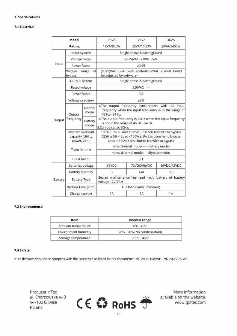
7.1 Electrical
Model 1KVA 2KVA 3KVA
Rating 1KVA/800W 2KVA/1600W 3KVA/2400W
Input
Input system Single phase & earth ground
Voltage range (90±5)VAC~ (300±5)VAC
Power factor ≥0.99
Voltage range of
bypass
(80±5)VAC~ (286±5)VAC (default: 80VAC~264VAC Could
be adjusted by software)
Output
Output system Single phase & earth ground
Rated voltage 220VAC ①
Power factor 0.8
Voltage precision ±2%
Output
frequency
Normal
mode
1.The output frequency synchronizes with the input
frequency when the input frequency is in the range of
46 Hz~ 54 Hz.
2.The output frequency is 50Hz when the input frequency
is not in the range of 46 Hz~ 54 Hz.
3.Can be set as 60Hz.
Battery
mode
Inverter overload
capacity (Utility
power, 25℃)
105% ± 5% < Load ≤ 125% ± 5% 50s transfer to bypass
125% ± 5% < Load <150% ± 5% 25s transfer to bypass
Load > 150% ± 5%, 300ms transfer to bypass
Transfer time 0ms (Normal mode←→ Battery mode)
<4ms (Normal mode←→Bypass mode)
Crest factor 3:1
Battery
Batteries voltage 36VDC 72VDC/96VDC 96VDC/72VDC
Battery quantity 3 6/8 8/6
Battery Type Sealed maintenance-free lead –acid battery of battery
voltage 12V/7AH
Backup Time (25℃) Full load≥5min (Standard)
Charge current 1A 1A 1A
7.2 Environmental
Item Normal range
Ambient temperature 0℃~ 40℃
Environment humidity 20%~ 90% (No condensation)
Storage temperature -15℃~ 45℃
7.4 Safety
nTec declares this device complies with the Directives as listed in this document: EMC 2004/108/WE, LVD 2006/95/WE.

INSTRUKCJA OBSŁUGI Zasilacz awaryjny (UPS)
MODEL: 53920 | 53921 | 53922
www.qoltec.com
PL
1
Spis treści
1 Wstęp .......................................................................................................................................................................................................................... 2
1.1 Opis często używanych symboli .................................................................................................................................................................... 2
1.2 Środki ostrożności ........................................................................................................................................................................................... 2
2 Opis produktu ............................................................................................................................................................................................................ 2
2.1 Modele UPS i ich konfiguracja........................................................................................................................................................................ 2
2.2 Budowa UPS .................................................................................................................................................................................................... 3
2.3 Schemat pracy UPS ......................................................................................................................................................................................... 3
3 Montaż ........................................................................................................................................................................................................................ 3
3.1 Rozpakowywanie ............................................................................................................................................................................................. 3
3.2 Procedura montażu ........................................................................................................................................................................................ 4
3.3 Procedura okablowania .................................................................................................................................................................................. 4
3.3.1 Podłączenie kabla wejściowego i wyjściowego .................................................................................................................................. 4
3.3.2 Podłączanie UPS z komputerem – inteligentny slot .......................................................................................................................... 5
3.3.3 Interfejs komunikacyjny – Port RS232 ................................................................................................................................................. 5
4 Obsługa UPS z wyświetlaczem LCD ......................................................................................................................................................................... 6
4.1 Funkcje wyświetlacza LCD .............................................................................................................................................................................. 6
4.2 Wygląd wyświetlacza w poszczególnych trybach pracy .............................................................................................................................. 6
4.2.1 Tryb normalny ....................................................................................................................................................................................... 7
4.2.2 Tryb akumulatora.................................................................................................................................................................................. 7
4.2.3 Tryb obejścia (bypass) .......................................................................................................................................................................... 8
4.2.4 Komunikaty wyświetlacza LCD podczas wykrycia błędu ................................................................................................................... 8
4.3 Eksploatacja ..................................................................................................................................................................................................... 9
4.3.1 Procedura włączania i wyłączania UPS ............................................................................................................................................... 9
4.3.2 Przeprowadzanie autodiagnozy akumulatora ................................................................................................................................. 10
4.3.3 Ustawienia napięcia wyjściowego oraz częstotliwości .................................................................................................................... 10
5 Konserwacja ............................................................................................................................................................................................................. 10
5.1 Konserwacja akumulatorów ........................................................................................................................................................................ 10
5.2 Okresowe sprawdzanie sprawności UPS .................................................................................................................................................... 10
6 Rozwiązywanie problemów .................................................................................................................................................................................... 11
7 Specyfikacja .............................................................................................................................................................................................................. 12
7.1 Elektryczna ..................................................................................................................................................................................................... 12
7.2 Środowiskowa ............................................................................................................................................................................................... 13
7.3 Normy bezpieczeństwa ................................................................................................................................................................................ 13
2
1 Wstęp
1.1 Opis często używanych symboli
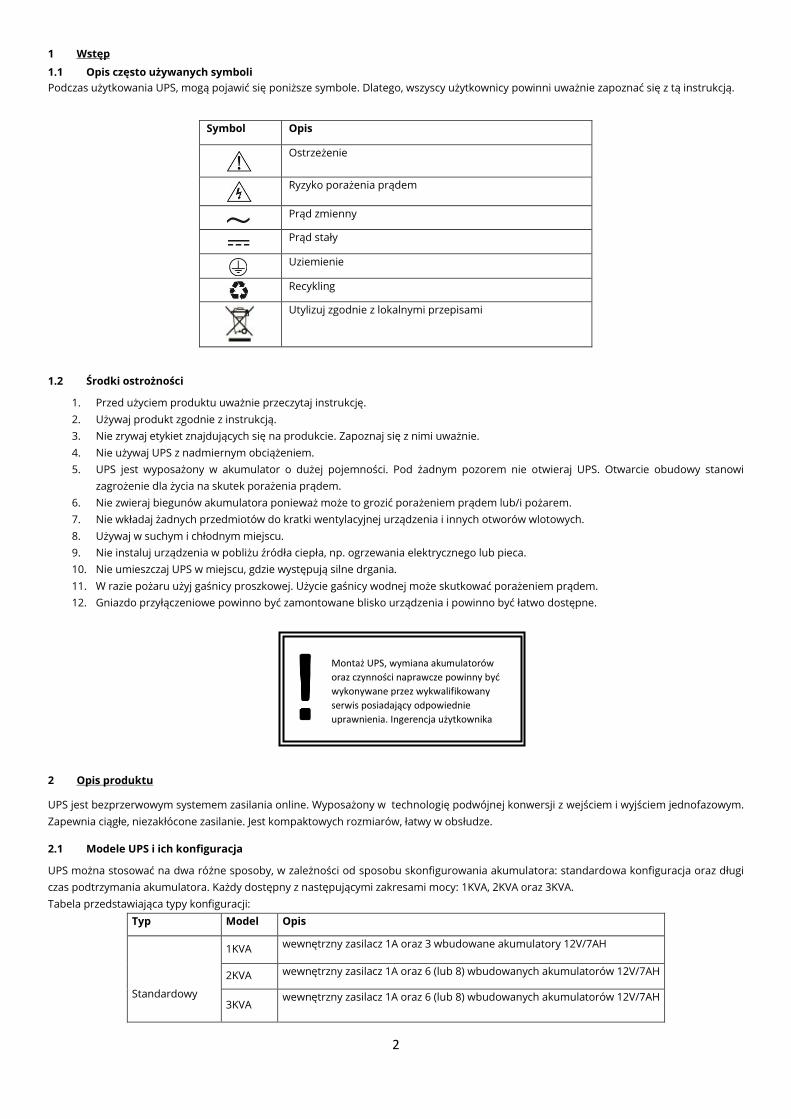
Podczas użytkowania UPS, mogą pojawić się poniższe symbole. Dlatego, wszyscy użytkownicy powinni uważnie zapoznać się z tą instrukcją.
Symbol Opis
Ostrzeżenie
Ryzyko porażenia prądem
Prąd zmienny
Prąd stały
Uziemienie
Recykling
Utylizuj zgodnie z lokalnymi przepisami
1.2 Środki ostrożności
1. Przed użyciem produktu uważnie przeczytaj instrukcję.
2. Używaj produkt zgodnie z instrukcją.
3. Nie zrywaj etykiet znajdujących się na produkcie. Zapoznaj się z nimi uważnie.
4. Nie używaj UPS z nadmiernym obciążeniem.
5. UPS jest wyposażony w akumulator o dużej pojemności. Pod żadnym pozorem nie otwieraj UPS. Otwarcie obudowy stanowi
zagrożenie dla życia na skutek porażenia prądem.
6. Nie zwieraj biegunów akumulatora ponieważ może to grozić porażeniem prądem lub/i pożarem.
7. Nie wkładaj żadnych przedmiotów do kratki wentylacyjnej urządzenia i innych otworów wlotowych.
8. Używaj w suchym i chłodnym miejscu.
9. Nie instaluj urządzenia w pobliżu źródła ciepła, np. ogrzewania elektrycznego lub pieca.
10. Nie umieszczaj UPS w miejscu, gdzie występują silne drgania.
11. W razie pożaru użyj gaśnicy proszkowej. Użycie gaśnicy wodnej może skutkować porażeniem prądem.
12. Gniazdo przyłączeniowe powinno być zamontowane blisko urządzenia i powinno być łatwo dostępne.
2 Opis produktu
UPS jest bezprzerwowym systemem zasilania online. Wyposażony w technologię podwójnej konwersji z wejściem i wyjściem jednofazowym.
Zapewnia ciągłe, niezakłócone zasilanie. Jest kompaktowych rozmiarów, łatwy w obsłudze.
2.1 Modele UPS i ich konfiguracja
UPS można stosować na dwa różne sposoby, w zależności od sposobu skonfigurowania akumulatora: standardowa konfiguracja oraz długi
czas podtrzymania akumulatora. Każdy dostępny z następującymi zakresami mocy: 1KVA, 2KVA oraz 3KVA.
Tabela przedstawiająca typy konfiguracji:
Typ Model Opis
Standardowy
1KVA wewnętrzny zasilacz 1A oraz 3 wbudowane akumulatory 12V/7AH
2KVA wewnętrzny zasilacz 1A oraz 6 (lub 8) wbudowanych akumulatorów 12V/7AH
3KVA wewnętrzny zasilacz 1A oraz 6 (lub 8) wbudowanych akumulatorów 12V/7AH
Montaż UPS, wymiana akumulatorów
oraz czynności naprawcze powinny być
wykonywane przez wykwalifikowany
serwis posiadający odpowiednie
uprawnienia. Ingerencja użytkownika
jest zabroniona ponieważ grozi utratą
3
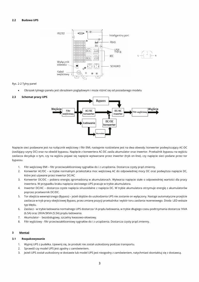
2.2 Budowa UPS
Rys. 2-2 Tylny panel
• Obrazek tylnego panelu jest obrazkiem poglądowym i może różnić się od posiadanego modelu
2.3 Schemat pracy UPS
Napięcie sieci podawane jest na rozłącznik wejściowy i filtr EMI, następnie rozdzielane jest na dwa obwody: konwerter podwyższający AC-DC
(zasilający szyny DC) oraz na obwód bypassu. Napięcie z konwertera AC-DC zasila akumulator oraz inwertor. Przekaźnik bypassu na wyjściu
zasilacza decyduje o tym, czy na wyjściu pojawi się napięcie wytwarzane przez inwerter (tryb on-line), czy napięcie sieci podane przez tor
bypassu.
1. Filtr wejściowy EMI – filtr przeciwzakłóceniowy sygnałów do i z urządzenia. Dostarcza czysty prąd zmienny.
2. Konwerter AC/DC – w trybie normalnym przekształca moc wejściową AC do odpowiedniej mocy DC oraz podwyższa napięcie DC,
które jest używane przez inwertor DC/AC
3. Konwerter DC/DC – pobiera energię zgromadzoną w akumulatorach. Wytwarza napięcie stałe o odpowiedniej wartości dla pracy
inwertera. W przypadku braku napięcia sieciowego UPS pracuje w trybie akumulatora.
4. Inwerter DC/AC – dostarcza czyste napięcia sinusoidalne z napięcia DC. W trybie akumulatora otrzymuje energię z akumulatorów
poprzez przetwornik DC/DC.
5. Tor obejścia wewnętrznego (Bypass) – jeżeli dojdzie do uszkodzenia UPS nie zostanie on wyłączony. Nastąpi automatyczne przejście
zasilacza w tryb pracy obejściowej Bypass, przez zmianę pozycji przekaźnika i wybór toru zasilania rezerwowego. Dioda LED wskaże
typ błędu.
6. Zasilacz - w trybie ładowania normalnego UPS dostarcza 1A prądu ładowania, w trybie długiego czasu podtrzymania dostarcza 1KVA
(6.5A) oraz 2KVA/3KVA (5.5A) prądu ładowania.
7. Akumulator - bezobsługowy, szczelny kwasowo-ołowiowy.
8. Filtr wyjściowy - filtr przeciwzakłóceniowy sygnałów do i z urządzenia. Dostarcza czysty prąd zmienny.
3 Montaż
3.1 Rozpakowywanie
1. Wyjmij UPS z pudełka. Upewnij się, że produkt nie został uszkodzony podczas transportu.
2. Sprawdź czy model UPS jest zgodny z zamówieniem.
3. Jeżeli UPS został uszkodzony w dostawie lub model UPS jest niezgodny z zamówieniem, natychmiast skontaktuj się z dostawcą.
4
3.2 Procedura montażu
1. Nie umieszczaj UPS w pobliżu: wody, łatwopalnych gazów, środków korozyjnych.
2. Ustaw UPS tylko w pozycji pionowej. Aby zapewnić dobrą wentylację UPS, nie blokuj kratki wentylacyjnej, portu wyjściowego i
bocznych paneli.
3. W przypadku gdy UPS został umieszczony w niskiej temperaturze, wewnątrz obudowy może wystąpić zjawisko skraplania pary
wodnej. Należy przed montażem i użyciem poczekać, aż UPS całkowicie wyschnie. W innym przypadku może to grozić porażeniem
prądem.
4. W razie pojawienia się zagrożenia, wyjmij wtyczkę z gniazdka oraz odetnij napięcie wyjściowe akumulatora. Wszystkie gniazdka
muszą być uziemione.
3.3 Procedura okablowania
3.3.1 Podłączenie kabla wejściowego i wyjściowego
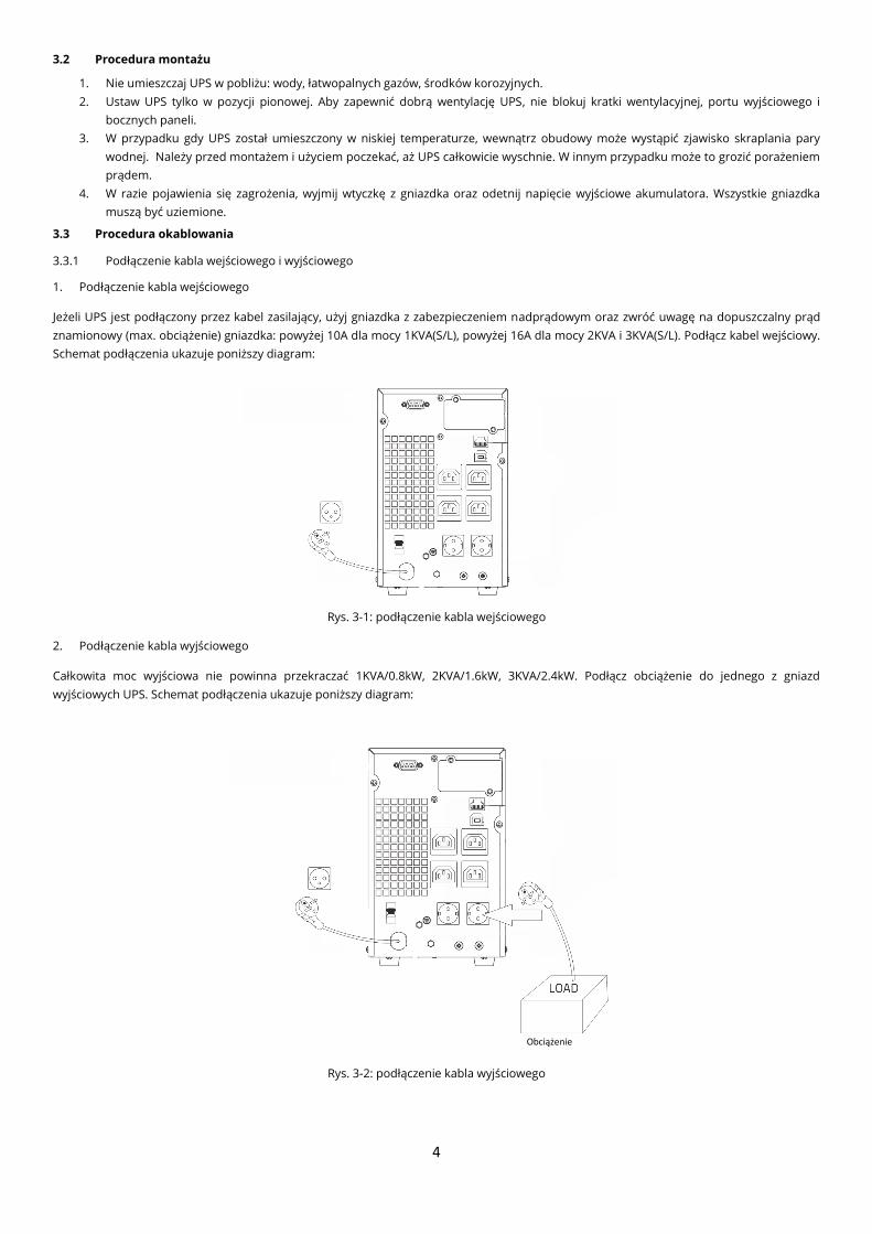
1. Podłączenie kabla wejściowego
Jeżeli UPS jest podłączony przez kabel zasilający, użyj gniazdka z zabezpieczeniem nadprądowym oraz zwróć uwagę na dopuszczalny prąd
znamionowy (max. obciążenie) gniazdka: powyżej 10A dla mocy 1KVA(S/L), powyżej 16A dla mocy 2KVA i 3KVA(S/L). Podłącz kabel wejściowy.
Schemat podłączenia ukazuje poniższy diagram:
Rys. 3-1: podłączenie kabla wejściowego
2. Podłączenie kabla wyjściowego
Całkowita moc wyjściowa nie powinna przekraczać 1KVA/0.8kW, 2KVA/1.6kW, 3KVA/2.4kW. Podłącz obciążenie do jednego z gniazd
wyjściowych UPS. Schemat podłączenia ukazuje poniższy diagram:
Rys. 3-2: podłączenie kabla wyjściowego
Obciążenie
5
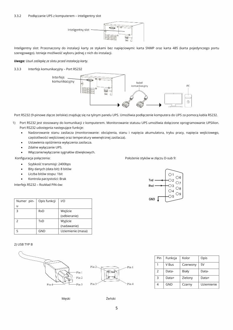
3.3.2 Podłączanie UPS z komputerem – inteligentny slot
Inteligentny slot: Przeznaczony do instalacji karty ze stykami bez napięciowymi: karta SNMP oraz karta 485 (karta pojedynczego portu
szeregowego). Istnieje możliwość wyboru jednej z nich do instalacji.
Uwaga: Usuń zaślepkę ze slotu przed instalacją karty.
3.3.3 Interfejs komunikacyjny – Port RS232
Port RS232 (9-pinowe złącze żeńskie) znajduję się na tylnym panelu UPS. Umożliwia podłączenie komputera do UPS za pomocą kabla RS232.
1) Port RS232 jest stosowany do komunikacji z komputerem. Monitorowanie statusu UPS umożliwia dołączone oprogramowanie UPSilion.
Port RS232 udostępnia następujące funkcje:
• Nadzorowanie stanu zasilacza (monitorowanie: obciążenia, stanu i napięcia akumulatora, trybu pracy, napięcia wejściowego,
częstotliwości wejściowej oraz temperatury wewnętrznej zasilacza).
• Ustawienia opóźnienia wyłączenia zasilacza.
• Zdalne wyłączanie UPS.
• Włączanie/wyłączanie sygnałów dźwiękowych.
Konfiguracja połączenia: Położenie styków w złączu D-sub 9:
• Szybkość transmisji: 2400bps
• Bity danych (data bit): 8 bitów
• Liczba bitów stopu: 1bit
• Kontrola parzystości: Brak
Interfejs RS232 – Rozkład PIN-ów:
Numer pin-
u
Opis funkcji I/O
3 RxD Wejście
(odbieranie)
2 TxD Wyjście
(nadawanie)
5 GND Uziemienie (masa)
2) USB TYP B
Męski Żeński
Pin Funkcja Kolor Opis
1 V Bus Czerwony 5V
2 Data- Biały Data-
3 Data+ Zielony Data+
4 GND Czarny Uziemienie
6
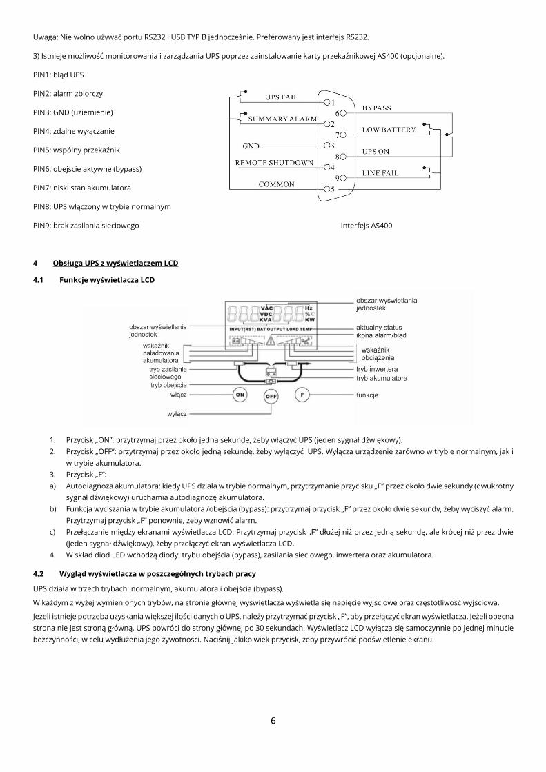
Uwaga: Nie wolno używać portu RS232 i USB TYP B jednocześnie. Preferowany jest interfejs RS232.
3) Istnieje możliwość monitorowania i zarządzania UPS poprzez zainstalowanie karty przekaźnikowej AS400 (opcjonalne).
PIN1: błąd UPS
PIN2: alarm zbiorczy
PIN3: GND (uziemienie)
PIN4: zdalne wyłączanie
PIN5: wspólny przekaźnik
PIN6: obejście aktywne (bypass)
PIN7: niski stan akumulatora
PIN8: UPS włączony w trybie normalnym
PIN9: brak zasilania sieciowego Interfejs AS400
4 Obsługa UPS z wyświetlaczem LCD
4.1 Funkcje wyświetlacza LCD
1. Przycisk „ON”: przytrzymaj przez około jedną sekundę, żeby włączyć UPS (jeden sygnał dźwiękowy).
2. Przycisk „OFF”: przytrzymaj przez około jedną sekundę, żeby wyłączyć UPS. Wyłącza urządzenie zarówno w trybie normalnym, jak i
w trybie akumulatora.
3. Przycisk „F”:
a) Autodiagnoza akumulatora: kiedy UPS działa w trybie normalnym, przytrzymanie przycisku „F” przez około dwie sekundy (dwukrotny
sygnał dźwiękowy) uruchamia autodiagnozę akumulatora.
b) Funkcja wyciszania w trybie akumulatora /obejścia (bypass): przytrzymaj przycisk „F” przez około dwie sekundy, żeby wyciszyć alarm.
Przytrzymaj przycisk „F” ponownie, żeby wznowić alarm.
c) Przełączanie między ekranami wyświetlacza LCD: Przytrzymaj przycisk „F” dłużej niż przez jedną sekundę, ale krócej niż przez dwie
(jeden sygnał dźwiękowy), żeby przełączyć ekran wyświetlacza LCD.
4. W skład diod LED wchodzą diody: trybu obejścia (bypass), zasilania sieciowego, inwertera oraz akumulatora.
4.2 Wygląd wyświetlacza w poszczególnych trybach pracy
UPS działa w trzech trybach: normalnym, akumulatora i obejścia (bypass).
W każdym z wyżej wymienionych trybów, na stronie głównej wyświetlacza wyświetla się napięcie wyjściowe oraz częstotliwość wyjściowa.
Jeżeli istnieje potrzeba uzyskania większej ilości danych o UPS, należy przytrzymać przycisk „F”, aby przełączyć ekran wyświetlacza. Jeżeli obecna
strona nie jest stroną główną, UPS powróci do strony głównej po 30 sekundach. Wyświetlacz LCD wyłącza się samoczynnie po jednej minucie
bezczynności, w celu wydłużenia jego żywotności. Naciśnij jakikolwiek przycisk, żeby przywrócić podświetlenie ekranu.
7
4.2.1 Tryb normalny
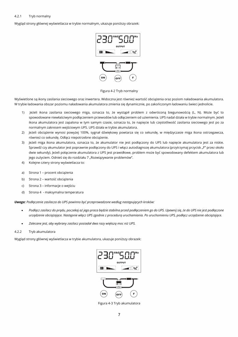
Wygląd strony głównej wyświetlacza w trybie normalnym, ukazuje poniższy obrazek:
Figura 4-2 Tryb normalny
Wyświetlone są ikony zasilania sieciowego oraz inwertera. Widoczna jest również wartość obciążenia oraz poziom naładowania akumulatora.
W trybie ładowania obszar poziomu naładowania akumulatora zmienia się dynamicznie, po zakończonym ładowaniu świeci jednolicie.
1) Jeżeli ikona zasilania sieciowego miga, oznacza to, że wystąpił problem z odwróconą biegunowością (L, N). Może być to
spowodowane niewłaściwym podłączeniem przewodów lub odłączeniem od uziemienia. UPS nadal działa w trybie normalnym. Jeżeli
ikona akumulatora jest zapalona w tym samym czasie, oznacza to, że napięcie lub częstotliwość zasilania sieciowego jest po za
normalnym zakresem wejściowym UPS. UPS działa w trybie akumulatora.
2) Jeżeli obciążenie wynosi powyżej 100%, sygnał dźwiękowy powtarza się co sekundę, w międzyczasie miga ikona ostrzegawcza,
również co sekundę. Odłącz niepotrzebne obciążenie.
3) Jeżeli miga ikona akumulatora, oznacza to, że akumulator nie jest podłączony do UPS lub napięcie akumulatora jest za niskie.
Sprawdź czy akumulator jest poprawnie podłączony do UPS i włącz autodiagnozę akumulatora (przytrzymaj przycisk „F” przez około
dwie sekundy). Jeżeli połączenie akumulatora z UPS jest prawidłowe, problem może być spowodowany defektem akumulatora lub
jego zużyciem. Odnieś się do rozdziału 7 „Rozwiązywanie problemów”.
4) Kolejne cztery strony wyświetlacza to:
a) Strona 1 – procent obciążenia
b) Strona 2 – wartość obciążenia
c) Strona 3 – informacje o wejściu
d) Strona 4 - maksymalna temperatura
Uwaga: Podłączenie zasilacza do UPS powinno być przeprowadzone według następujących kroków:
• Podłącz zasilacz do prądu, poczekaj aż jego praca będzie stabilna przed podłączeniem go do UPS. Upewnij się, że do UPS nie jest podłączone
urządzenie obciążające. Następnie włącz UPS zgodnie z procedurą uruchamiania. Po uruchomieniu UPS, podłącz urządzenie obciążające.
• Zalecane jest, aby wybrany zasilacz posiadał dwa razy większą moc niż UPS.
4.2.2 Tryb akumulatora
Wygląd strony głównej wyświetlacza w trybie akumulatora, ukazuje poniższy obrazek:
Figura 4-3 Tryb akumulatora
8
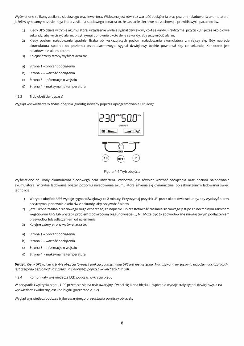
Wyświetlone są ikony zasilania sieciowego oraz inwertera. Widoczna jest również wartość obciążenia oraz poziom naładowania akumulatora.
Jeżeli w tym samym czasie miga ikona zasilania sieciowego oznacza to, że zasilanie sieciowe nie zachowuje prawidłowych parametrów.
1) Kiedy UPS działa w trybie akumulatora, urządzenie wydaje sygnał dźwiękowy co 4 sekundy. Przytrzymaj przycisk „F” przez około dwie
sekundy, aby wyciszyć alarm, przytrzymaj ponownie około dwie sekundy, aby przywrócić alarm.
2) Kiedy poziom naładowania spadnie, liczba pól wskazujących poziom naładowania akumulatora zmniejszy się. Gdy napięcie
akumulatora spadnie do poziomu przed-alarmowego, sygnał dźwiękowy będzie powtarzał się, co sekundę. Konieczne jest
naładowanie akumulatora.
3) Kolejne cztery strony wyświetlacza to:
a) Strona 1 – procent obciążenia
b) Strona 2 – wartość obciążenia
c) Strona 3 – informacje o wejściu
d) Strona 4 - maksymalna temperatura
4.2.3 Tryb obejścia (bypass)
Wygląd wyświetlacza w trybie obejścia (skonfigurowany poprzez oprogramowanie UPSilon):
Figura 4-4 Tryb obejścia
Wyświetlone są ikony akumulatora sieciowego oraz inwertera. Widoczna jest również wartość obciążenia oraz poziom naładowania
akumulatora. W trybie ładowania obszar poziomu naładowania akumulatora zmienia się dynamicznie, po zakończonym ładowaniu świeci
jednolicie.
1) W trybie obejścia UPS wydaje sygnał dźwiękowy co 2 minuty. Przytrzymaj przycisk „F” przez około dwie sekundy, aby wyciszyć alarm,
przytrzymaj ponownie około dwie sekundy, aby przywrócić alarm.
2) Jeżeli ikona zasilania sieciowego miga oznacza to, że napięcie lub częstotliwość zasilania sieciowego jest po za normalnym zakresem
wejściowym UPS lub wystąpił problem z odwróconą biegunowością (L, N). Może być to spowodowane niewłaściwym podłączeniem
przewodów lub odłączeniem od uziemienia.
3) Kolejne cztery strony wyświetlacza to:
a) Strona 1 – procent obciążenia
b) Strona 2 – wartość obciążenia
c) Strona 3 – informacje o wejściu
d) Strona 4 - maksymalna temperatura
Uwaga: Kiedy UPS działa w trybie obejścia (bypass), funkcja podtrzymania UPS jest niedostępna. Moc używana do zasilenia urządzeń obciążających
jest czerpana bezpośrednio z zasilania sieciowego poprzez wewnętrzny filtr EMI.
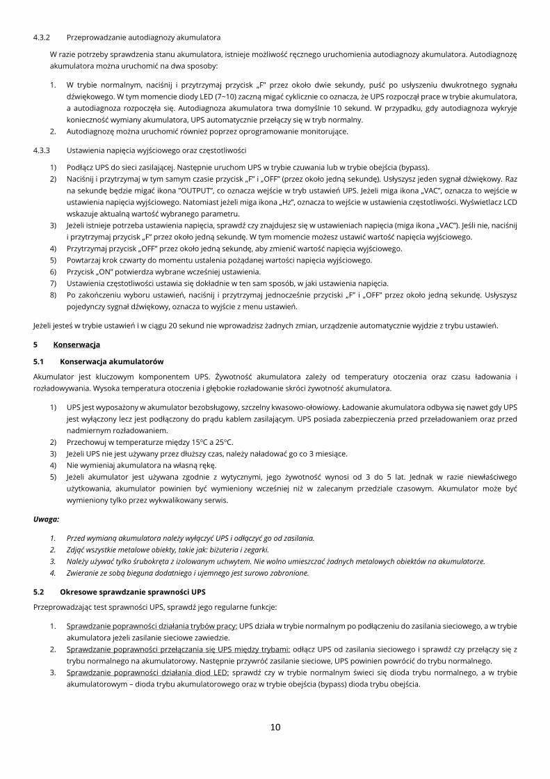
4.2.4 Komunikaty wyświetlacza LCD podczas wykrycia błędu
W przypadku wykrycia błędu, UPS przełącza się na tryb awaryjny. Świeci się ikona błędu, urządzenie wydaje stały sygnał dźwiękowy, a na
wyświetlaczu widoczny jest kod błędu (patrz tabela 7-2).
Wygląd wyświetlacz podczas trybu awaryjnego przedstawia poniższy obrazek:
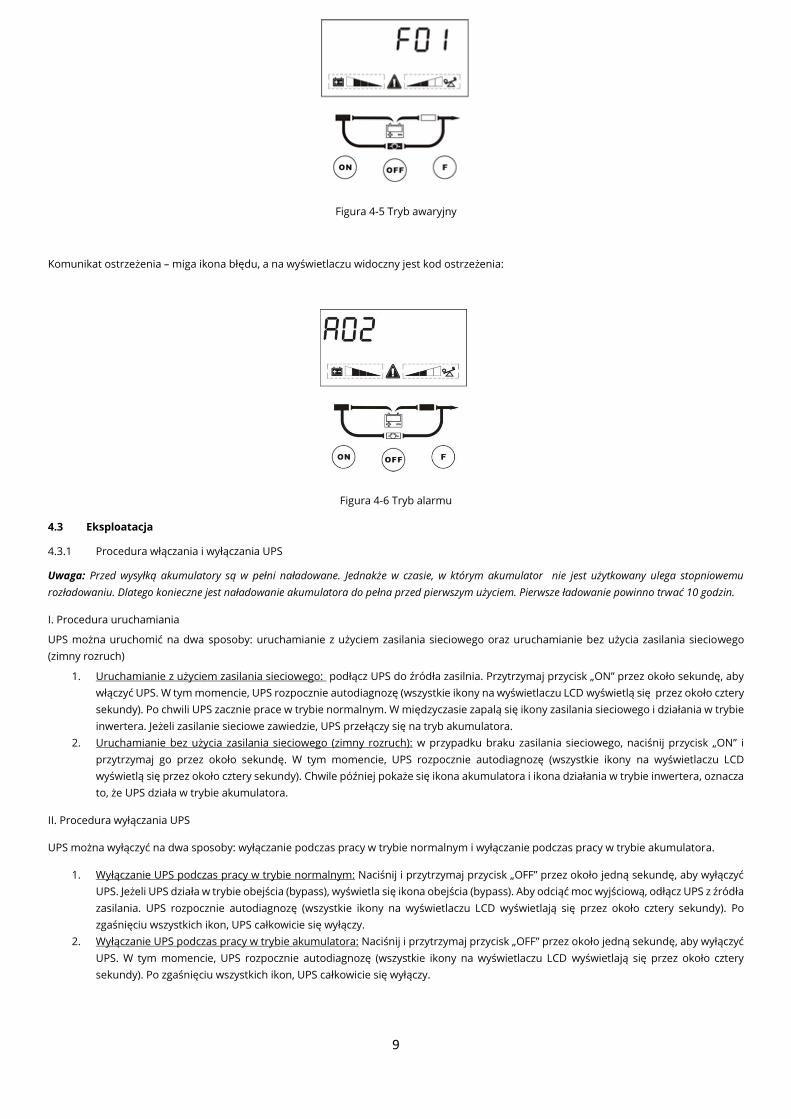
9
Figura 4-5 Tryb awaryjny
Komunikat ostrzeżenia – miga ikona błędu, a na wyświetlaczu widoczny jest kod ostrzeżenia:
Figura 4-6 Tryb alarmu
4.3 Eksploatacja
4.3.1 Procedura włączania i wyłączania UPS
Uwaga: Przed wysyłką akumulatory są w pełni naładowane. Jednakże w czasie, w którym akumulator nie jest użytkowany ulega stopniowemu
rozładowaniu. Dlatego konieczne jest naładowanie akumulatora do pełna przed pierwszym użyciem. Pierwsze ładowanie powinno trwać 10 godzin.
I. Procedura uruchamiania
UPS można uruchomić na dwa sposoby: uruchamianie z użyciem zasilania sieciowego oraz uruchamianie bez użycia zasilania sieciowego
(zimny rozruch)
1. Uruchamianie z użyciem zasilania sieciowego: podłącz UPS do źródła zasilnia. Przytrzymaj przycisk „ON” przez około sekundę, aby
włączyć UPS. W tym momencie, UPS rozpocznie autodiagnozę (wszystkie ikony na wyświetlaczu LCD wyświetlą się przez około cztery
sekundy). Po chwili UPS zacznie prace w trybie normalnym. W międzyczasie zapalą się ikony zasilania sieciowego i działania w trybie
inwertera. Jeżeli zasilanie sieciowe zawiedzie, UPS przełączy się na tryb akumulatora.
2. Uruchamianie bez użycia zasilania sieciowego (zimny rozruch): w przypadku braku zasilania sieciowego, naciśnij przycisk „ON” i
przytrzymaj go przez około sekundę. W tym momencie, UPS rozpocznie autodiagnozę (wszystkie ikony na wyświetlaczu LCD
wyświetlą się przez około cztery sekundy). Chwile później pokaże się ikona akumulatora i ikona działania w trybie inwertera, oznacza
to, że UPS działa w trybie akumulatora.
II. Procedura wyłączania UPS
UPS można wyłączyć na dwa sposoby: wyłączanie podczas pracy w trybie normalnym i wyłączanie podczas pracy w trybie akumulatora.
1. Wyłączanie UPS podczas pracy w trybie normalnym: Naciśnij i przytrzymaj przycisk „OFF” przez około jedną sekundę, aby wyłączyć
UPS. Jeżeli UPS działa w trybie obejścia (bypass), wyświetla się ikona obejścia (bypass). Aby odciąć moc wyjściową, odłącz UPS z źródła
zasilania. UPS rozpocznie autodiagnozę (wszystkie ikony na wyświetlaczu LCD wyświetlają się przez około cztery sekundy). Po
zgaśnięciu wszystkich ikon, UPS całkowicie się wyłączy.
2. Wyłączanie UPS podczas pracy w trybie akumulatora: Naciśnij i przytrzymaj przycisk „OFF” przez około jedną sekundę, aby wyłączyć
UPS. W tym momencie, UPS rozpocznie autodiagnozę (wszystkie ikony na wyświetlaczu LCD wyświetlają się przez około cztery
sekundy). Po zgaśnięciu wszystkich ikon, UPS całkowicie się wyłączy.
10
4.3.2 Przeprowadzanie autodiagnozy akumulatora
W razie potrzeby sprawdzenia stanu akumulatora, istnieje możliwość ręcznego uruchomienia autodiagnozy akumulatora. Autodiagnozę
akumulatora można uruchomić na dwa sposoby:
1. W trybie normalnym, naciśnij i przytrzymaj przycisk „F” przez około dwie sekundy, puść po usłyszeniu dwukrotnego sygnału
dźwiękowego. W tym momencie diody LED (7~10) zaczną migać cyklicznie co oznacza, że UPS rozpoczął prace w trybie akumulatora,
a autodiagnoza rozpoczęła się. Autodiagnoza akumulatora trwa domyślnie 10 sekund. W przypadku, gdy autodiagnoza wykryje
konieczność wymiany akumulatora, UPS automatycznie przełączy się w tryb normalny.
2. Autodiagnozę można uruchomić również poprzez oprogramowanie monitorujące.
4.3.3 Ustawienia napięcia wyjściowego oraz częstotliwości
1) Podłącz UPS do sieci zasilającej. Następnie uruchom UPS w trybie czuwania lub w trybie obejścia (bypass).
2) Naciśnij i przytrzymaj w tym samym czasie przycisk „F” i „OFF” (przez około jedną sekundę). Usłyszysz jeden sygnał dźwiękowy. Raz
na sekundę będzie migać ikona ”OUTPUT”, co oznacza wejście w tryb ustawień UPS. Jeżeli miga ikona „VAC”, oznacza to wejście w
ustawienia napięcia wyjściowego. Natomiast jeżeli miga ikona „Hz”, oznacza to wejście w ustawienia częstotliwości. Wyświetlacz LCD
wskazuje aktualną wartość wybranego parametru.
3) Jeżeli istnieje potrzeba ustawienia napięcia, sprawdź czy znajdujesz się w ustawieniach napięcia (miga ikona „VAC”). Jeśli nie, naciśnij
i przytrzymaj przycisk „F” przez około jedną sekundę. W tym momencie możesz ustawić wartość napięcia wyjściowego.
4) Przytrzymaj przycisk „OFF” przez około jedną sekundę, aby zmienić wartość napięcia wyjściowego.
5) Powtarzaj krok czwarty do momentu ustalenia pożądanej wartości napięcia wyjściowego.
6) Przycisk „ON” potwierdza wybrane wcześniej ustawienia.
7) Ustawienia częstotliwości ustawia się dokładnie w ten sam sposób, w jaki ustawienia napięcia.
8) Po zakończeniu wyboru ustawień, naciśnij i przytrzymaj jednocześnie przyciski „F” i „OFF” przez około jedną sekundę. Usłyszysz
pojedynczy sygnał dźwiękowy, oznacza to wyjście z menu ustawień.
Jeżeli jesteś w trybie ustawień i w ciągu 20 sekund nie wprowadzisz żadnych zmian, urządzenie automatycznie wyjdzie z trybu ustawień.
5 Konserwacja
5.1 Konserwacja akumulatorów
Akumulator jest kluczowym komponentem UPS. Żywotność akumulatora zależy od temperatury otoczenia oraz czasu ładowania i
rozładowywania. Wysoka temperatura otoczenia i głębokie rozładowanie skróci żywotność akumulatora.
1) UPS jest wyposażony w akumulator bezobsługowy, szczelny kwasowo-ołowiowy. Ładowanie akumulatora odbywa się nawet gdy UPS
jest wyłączony lecz jest podłączony do prądu kablem zasilającym. UPS posiada zabezpieczenia przed przeładowaniem oraz przed
nadmiernym rozładowaniem.
2) Przechowuj w temperaturze między 15oC a 25oC.
3) Jeżeli UPS nie jest używany przez dłuższy czas, należy naładować go co 3 miesiące.
4) Nie wymieniaj akumulatora na własną rękę.
5) Jeżeli akumulator jest używana zgodnie z wytycznymi, jego żywotność wynosi od 3 do 5 lat. Jednak w razie niewłaściwego
użytkowania, akumulator powinien być wymieniony wcześniej niż w zalecanym przedziale czasowym. Akumulator może być
wymieniony tylko przez wykwalikowany serwis.
Uwaga:
1. Przed wymianą akumulatora należy wyłączyć UPS i odłączyć go od zasilania.
2. Zdjąć wszystkie metalowe obiekty, takie jak: biżuteria i zegarki.
3. Należy używać tylko śrubokręta z izolowanym uchwytem. Nie wolno umieszczać żadnych metalowych obiektów na akumulatorze.
4. Zwieranie ze sobą bieguna dodatniego i ujemnego jest surowo zabronione.
5.2 Okresowe sprawdzanie sprawności UPS
Przeprowadzając test sprawności UPS, sprawdź jego regularne funkcje:
1. Sprawdzanie poprawności działania trybów pracy: UPS działa w trybie normalnym po podłączeniu do zasilania sieciowego, a w trybie
akumulatora jeżeli zasilanie sieciowe zawiedzie.
2. Sprawdzanie poprawności przełączania się UPS między trybami: odłącz UPS od zasilania sieciowego i sprawdź czy przełączy się z
trybu normalnego na akumulatorowy. Następnie przywróć zasilanie sieciowe, UPS powinien powrócić do trybu normalnego.
3. Sprawdzanie poprawności działania diod LED: sprawdź czy w trybie normalnym świeci się dioda trybu normalnego, a w trybie
akumulatorowym – dioda trybu akumulatorowego oraz w trybie obejścia (bypass) dioda trybu obejścia.
11
6 Rozwiązywanie problemów
Poniższe tabele przedstawiają opisy błędów, które mogą się pojawić podczas normalnego użytkowania. Jeśli UPS przestanie działać
prawidłowo, podążaj za następującymi radami, przed skontaktowaniem się z centrum serwisowym.
Błąd
Możliwa przyczyna Rozwiązanie Kod
błędu/ostrzeżenia
Ikona
błędu Alarm
F01 Świeci na
stałe
Stały sygnał
dźwiękowy Błąd wewnętrzny
Skontaktuj się z dystrybutorem
lub centrum serwisowym.
F02 Świeci na
stałe
Stały sygnał
dźwiękowy Błąd wewnętrzny
Skontaktuj się z dystrybutorem
lub centrum serwisowym.
F03 Świeci na
stałe
Stały sygnał
dźwiękowy Błąd wewnętrzny
Skontaktuj się z dystrybutorem
lub centrum serwisowym.
F04 Świeci na
stałe
Stały sygnał
dźwiękowy Zwarcie na wyjściu UPS
Wyłącz UPS. Odłącz wszystkie
urządzenie obciążające.
Sprawdź czy nie wystąpił błąd
urządzenia obciążającego.
Upewnij się, że nie wystąpiło
wewnętrzne zwarcie UPS przed
ponownym uruchomieniem.
Jeżeli wystąpiło wewnętrzne
zwarcie, skontaktuj się z
dystrybutorem lub centrum
serwisowym.
F05 Świeci na
stałe
Stały sygnał
dźwiękowy Błąd wewnętrzny
Skontaktuj się z dystrybutorem
lub centrum serwisowym.
F06 Świeci na
stałe
Stały sygnał
dźwiękowy Błąd wewnętrzny
Skontaktuj się z dystrybutorem
lub centrum serwisowym.
F07 Świeci na
stałe
Stały sygnał
dźwiękowy UPS przeciążony
Odłącz mniej wrażliwe
urządzenia obciążające.
F08 Świeci na
stałe
Stały sygnał
dźwiękowy UPS przegrzany
Upewnij się, że UPS nie jest
przeciążony. Sprawdź czy
wentylator lub jego osłona nie
są zablokowane oraz czy
temperatura otoczenia nie jest
za wysoka. Poczekaj 10 minut,
aż UPS się ostudzi przed
ponownym uruchomieniem.
Jeśli to nie pomoże skontaktuj
się z serwisem.
F09 Świeci na
stałe
Stały sygnał
dźwiękowy Zasilacz UPS jest uszkodzony
Skontaktuj się z dystrybutorem
lub centrum serwisowym.
F11 Świeci na
stałe
Stały sygnał
dźwiękowy Błąd EPO
Sprawdź czy UPS działa
poprawnie, zresetuj EPO
A01 Miga raz na
sekundę
Sygnał dźwiękowy
co sekundę
Ostrzeżenie o możliwym
przeładowaniu
Odłącz mnie wrażliwe
urządzenia obciążające.
A02 Miga raz na
sekundę
Sygnał dźwiękowy
raz na sekundę Niskie napięcie akumulatora
Przełącz UPS na zasilanie
awaryjne. Wyjście UPS zostanie
wyłączone
A03 Miga raz na
sekundę
Stały sygnał
dźwiękowy Nieprawidłowe zasilanie UPS
Sprawdź poprawność
podłączenia akumulatora do
UPS.
12
A04 Miga raz na
sekundę
Stały sygnał
dźwiękowy Przeładowanie akumulatora
Skontaktuj się z dystrybutorem
lub centrum serwisowym.
A05 Miga raz na
sekundę
Sygnał dźwiękowy
raz na sekundę Błąd wentylatora
Sprawdź czy wentylator lub
jego osłona nie są
zablokowane.
A06 Miga raz na
sekundę
Sygnał dźwiękowy
co 2 minuty
Wystąpił problem z odwróconą
biegunowością (L, N). Może być to
spowodowane niewłaściwym
podłączeniem przewodów lub
odłączeniem od uziemienia.
Lub wystąpiło zbyt wysokie
napięcie pomiędzy przewodem
neutralnym i uziemieniem.
Sprawdź poprawność
podłączenia przewodów.
Upewnij się, że przewód
zielono-żółty jest prawidłowo
podłączony do uziemienia oraz
czy napięcie pomiędzy
przewodem neutralnym i
uziemieniem wynosi mniej niż
36VAC.
W razie potrzeby skontaktowanie się z centrum serwisowym, przygotuj następujące informacje:
• Numer modelu oraz numer seryjny UPS
• Datę pojawienia się błędu
• Dokładny opis błędu: wskazania wyświetlacza LCD, ostrzeżenia, stan zasilania oraz wartość obciążenia.
• Szczegóły dotyczące akumulatora - jeżeli jest to model UPS wyposażony w tryb długiego podtrzymywania akumulatora
7 Specyfikacja
7.1 Elektryczna
Model 1KVA 2KVA 3KVA
Wartość 1KVA/800W 2KVA/1600W 3KVA/2400W
Wejście
Układ wejściowy Jednofazowy z uziemieniem
Napięcie znamionowe 220~240VAC
Zakres napięcia (90±5)VAC~ (300±5)VAC
Współczynnik mocy ≥0.99
Zakres napięcia w trybie obejścia
(bypass)
(80±5)VAC~ (286±5)VAC (domyślnie: 80VAC~264VAC może być dostosowany przez
oprogramowanie)
Wyjście
Układ wyjściowy Jednofazowy z uziemieniem
Napięcie znamionowe 220~240VAC
Współczynnik mocy 0.8
Regulacja napięcia ±2%
Częstotliwość
Tryb normalny Częstotliwość wyjściowa synchronizuje się z częstotliwością wejściową kiedy
częstotliwość wejściowa mieści się w przedziale: 46Hz~54Hz
Częstotliwość wyjściowa wynosi 50Hz jeżeli częstotliwość wejściowa nie mieści się
w przedziale 46Hz~54Hz
Możliwość ustawienia częstotliwości 60Hz
Tryb
akumulatora
Odporność inwertera na
przeciążenia
105% ± 5% < obciążenia ≤ 125% ± 5% 50s przeniesienie na tryb obejścia (bypass)
125% ± 5% < obciążenia <150% ± 5% 25s przeniesienie na tryb obejścia (bypass)
obciążenia > 150% ± 5%, 300ms przeniesienie na tryb obejścia (bypass)
Czas przełączania 0ms (tryb normalny←→ tryb akumulatora)
<4ms (tryb normalny←→tryb obejścia - bypass)
Współczynnik szczytu 3:1
Akumulator
Napięcie akumulatora 36VDC 72VDC/96VDC 96VDC/72VDC
Ilość akumulatora 3 6/8 8/6
Typ akumulatora akumulator bezobsługowy, szczelny kwasowo-ołowiowy o napięciu 12V/7AH
Czas autonomii (25oC) 100% obciążenia ≥5min (Standard)
Prąd ładowania 1A 1A 1A
13
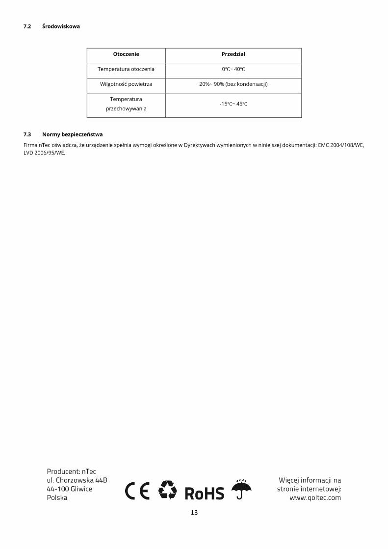
7.2 Środowiskowa
Otoczenie Przedział
Temperatura otoczenia 0℃~ 40℃
Wilgotność powietrza 20%~ 90% (bez kondensacji)
Temperatura
przechowywania -15℃~ 45℃
7.3 Normy bezpieczeństwa
Firma nTec oświadcza, że urządzenie spełnia wymogi określone w Dyrektywach wymienionych w niniejszej dokumentacji: EMC 2004/108/WE,
LVD 2006/95/WE.