User Manual medixX - KKT chillers · Dokument 83000002.Kf Page 6 of 106 2.2.2 medixX 60 Chiller...
106
User Manual medixX Models/Type: medixX 50 medixX 60 medixX 70 Serial number: 131/6002/00/serial/monthyear 144/6002/00/serial/monthyear 149/6002/00/serial/monthyear Following shall be filled by the owner Inventory number Place of installation Place of installation Safety first: The owner of this unit is responsible that everyone who is working on the unit observes the safety rules and reads the whole Manual/Install instructions and understands it. A wrong or sloppy maintained unit could cause high body risk or even risk of death.
-
Upload
trinhthien -
Category
Documents
-
view
214 -
download
0
Transcript of User Manual medixX - KKT chillers · Dokument 83000002.Kf Page 6 of 106 2.2.2 medixX 60 Chiller...

User ManualmedixX
Models/Type: medixX 50medixX 60medixX 70
Serial number: 131/6002/00/serial/monthyear 144/6002/00/serial/monthyear 149/6002/00/serial/monthyear
Following shall be filled by the owner
Inventory number
Place of installation
Place of installation
Safety first:The owner of this unit is responsible that everyone who is working on the unit observes the safetyrules and reads the whole Manual/Install instructions and understands it. A wrong or sloppy maintained unit could cause high body risk or even risk of death.

Dokument 83000002.KfPage 2 of 106
Contents 1 Warranty registration ..................................................................................................................... 4 2 Product specification ..................................................................................................................... 4 2.1 Intended use ................................................................................................................................ 4 2.2 Technical data ............................................................................................................................. 5 2.2.1 medixX 50 ................................................................................................................................ 5 2.2.2 medixX 60 ................................................................................................................................ 6 2.2.3 medixX 70 ................................................................................................................................ 7 2.3 General function and application range ....................................................................................... 8 2.3.1 Chiller ....................................................................................................................................... 9 2.3.1.1 Compressor ............................................................................................................................ 9 2.3.1.2 Condenser .............................................................................................................................. 9 2.3.1.3 Fans ....................................................................................................................................... 9 2.3.1.4 Evaporator ........................................................................................................................... 10 2.3.1.5 Pressure limiter .................................................................................................................... 10 2.3.1.5.1 Low pressure sensor (PSL) ................................................................................................. 10 2.3.1.5.2 High pressure limiter (PZH) ............................................................................................... 10 2.3.1.5.3 High pressure sensor ........................................................................................................ 10 2.3.1.6 switch cabinet ...................................................................................................................... 10 2.3.1.7 PCB board (printed circuit board) ......................................................................................... 10 2.3.1.8 Display Controller ................................................................................................................ 10 2.4 Pump ......................................................................................................................................... 11 2.4.1.1 Filter ball valve ..................................................................................................................... 11 2.5 Remaining risk-phrases .............................................................................................................. 12 2.5.1 Electrical risk .......................................................................................................................... 12 2.5.2 Mechanical risk ....................................................................................................................... 12 2.5.3 Chemical risk .......................................................................................................................... 12 2.6 Other risk .................................................................................................................................. 12 2.6.1 Safety data for refrigerant ...................................................................................................... 12 2.6.2 Safety data for Mineral oils ..................................................................................................... 13 3 Definition ..................................................................................................................................... 15 4 Check before installation .............................................................................................................. 16 4.1 Transport and Storage ............................................................................................................... 16 4.2 Safety regulating before use! ..................................................................................................... 18 4.3 Unpacking ................................................................................................................................. 18 4.4 Disposal of packing waste .......................................................................................................... 18 4.5 Checklist before and during installation ..................................................................................... 19 4.5.1 Installation ............................................................................................................................. 22 4.5.2 Piping connections ................................................................................................................. 22 4.5.3 Electrical connection .............................................................................................................. 23 4.5.4 EMC Compatibility and Grounding .......................................................................................... 24 4.5.5 Filling the system ................................................................................................................... 25 4.5.6 Static Fill pressure .................................................................................................................. 26 4.5.7 Draining air from the unit ....................................................................................................... 27 4.5.8 Decommissioning ................................................................................................................... 29 4.6 Demounting .............................................................................................................................. 29 4.7 Re-packaging ........................................................................................................................... 29 5 Instructions for use ...................................................................................................................... 30 5.1 Bringing into service .................................................................................................................. 30 5.1.1 General function of the control ................................................................................................ 33 5.2 Unexpected situation ................................................................................................................ 39
Dokument 83000002.KfPage 3 of 106
5.2.1 Emergency stop of control circuit (remote off) ........................................................................ 39 5.2.2 Procedure after an unexpected chiller off ............................................................................... 39 5.2.3 Procedure after high pressure fault ........................................................................................ 39 5.2.4 In case of an emergency/fire .................................................................................................. 39 5.3 Signals at the PCB ...................................................................................................................... 40 5.3.1 Collective fault / Customer Contact ........................................................................................ 40 5.3.2 Safety first – Personell protection ........................................................................................... 41 6 Keep in service and cleaning ......................................................................................................... 42 6.1 Safety regulating during Maintenance and Service ..................................................................... 43 6.2 Clean the condenser .................................................................................................................. 43 6.3 Keep in service and cleaning - performed by qualified technicians ............................................. 44 6.4 System log guidelines ................................................................................................................ 48 7 Fault analysis and Maintenance/Service ........................................................................................ 49 8 Options ........................................................................................................................................ 51 8.1 FCU – Free Cooling Unit .............................................................................................................. 51 8.2 FCU – Connections (FCU-Option) ................................................................................................ 52 9 Sparepartlist ................................................................................................................................ 55 9.1 Chiller ........................................................................................................................................ 55 9.2 FCU ........................................................................................................................................... 57 10 Attachment ................................................................................................................................. 58 10.1 Piping and Instruments Diagram P&ID ..................................................................................... 58 11 Automatic Airvent (shall be cleaned once per year) ..................................................................... 60 12 FANS .......................................................................................................................................... 61 13 Compressor 1 (speed controlled) ................................................................................................. 61 13.1 VFD-Drive for Compressor 1 ..................................................................................................... 62 14 Possible pump failures ................................................................................................................ 63 15 3-way valve for FCU (0-10VDC) ................................................................................................... 65 16 Electronic Expansion valve .......................................................................................................... 69 17 8-Bit-Failure code on PCB board ................................................................................................. 70 18 Filter ball valve ........................................................................................................................... 74 19 Tempearturesensor PT1000 resistance ........................................................................................ 75 19.1 Pressure sensor ........................................................................................................................ 76 20 Pressure, Temperature and Flow chart ........................................................................................ 77 21 Safety data for Antifrogen N ....................................................................................................... 78 21.1 Safety data for Dowtherm SR1 .................................................................................................. 85 21.2 Safety data for refrigerant oil .................................................................................................. 93 21.3 Safety data for refrigerant R407c ............................................................................................. 98 22 Wiring diagram ......................................................................................................................... 105 23 KKT Service ............................................................................................................................... 105 24 Declaration of Conformity (affect inside Europe) ...................................................................... 106

Dokument 83000002.KfPage 4 of 106
1 Warranty registration
To make a use of possibly warranty rights, it is necessary to complete the warranty registration, and send it back to KKT chillers.This has to be done by the end-user or installer promptly after the first start-up.
KKT chillers (ait-deutschland GmbH) will only accept warranty, if KKT has received the correctand completely filled out warranty registration.
Available @ www.kkt-chillers.com
2 Product specification
2.1 Intended useThe medixX-Chiller is a factory tested compression refrigerant system and shall only be used to cool liquidsregarding EN 378-1 4.4.2.2., with all for the fully automatic required components. The medixX-Chiller is foroutdoor use only. Housing, roofing or other constructions which is interrupting the airflow are prohibited.
The unit is fully automatically operating as soon the main switch is turned ON
Don´t run this equipment under potentially explosive atmosphere.
The system has to be de-energized before opening!
Only qualified mechanic are allowed to work on the system!
Refrigerant and water pipes are under pressure!
Refrigerant/water/motor/electrical parts could be hot and cold at the same time!
Use only allowed liquids!

Dokument 83000002.KfPage 5 of 106
2.2 Technical data
2.2.1 medixX 50
Manufacturer ait-deutschland GmbH Industriestraße 395359 Kasendorf GermanyT +49 9228 9977 0F +49 9228 9977 149
Chiller medixX 50
Type Air cooled water chiller with closed loop
Serial number 131.6002.00.xxxx.xxxx ← see nameplate
Year of manufacturing 20xx ← see nameplate (last 2 digits)
Cooling capacity tamb 49°C / at 12°C supply water temperature
45 kW
Refrigerant R407C
GWP 1774
Filling weight 13 kg
CO2 equivalent 23,1 t CO2
Coolant 62-65% potable water and 35-38% Ethylene Glycol
Chiller volume 10 liter
Discharge temperature 12 °C
Accuracy +/- 2K
Ambient temperature -25 – 49 °C
Air flow 37.000 m³/h
Protection class EN 60529 with closed housing
IP 54
Operating voltage 400V/50Hz and 480V/60Hz400V/60Hz (optional)
Full load amps 63 A
Control voltage 24 VDC
Sound pressure level in 5 m distance 70 dB(A)
Dimensions Length x Width x Height 2.145 mm x 1.100 mm x 2.050 mm
weight / operating weight 779 kg / 789 kg
Flow rate min. 3.7 m³/h / max. 5 m³/h
Pump pressure max. 6,8 bar
Leak-Test Attention: Safety valve-water 3bar/43PSI

Dokument 83000002.KfPage 6 of 106
2.2.2 medixX 60
Chiller Process water cooler
Typ medixX 60
Produce.-No.: 144.6002.00.xxxx.xxxx ← see nameplate
Year of Manufacturing 20xx ← see nameplate (last 2 digit)
Manufacturer ait-deutschland GmbHIndustriestraße 395359 Kasendorf GermanyT +49 9228 9977 0F +49 9228 9977 149
Refrigerant R407C
GWP 1774
Filling weight 13 kg
CO2 equivalent 23,1 t CO2
Cooling capacity [kW] 60 at 12°C Supply water temperature and 49°C ambient temperature
Operating liquid (water circuit) 62-65% potable water and35-38% Ethylene Glycol
Chiller volume [l] 11 liter
Discharge temperature [°C] 12
Temperature accuracy [K] +/- 2
Ambient temperature limit [°C] -25 / 49
Air flow [m³/h] 37000
Protection classification EN 60529 IP54 [with closed housing]
Electrical connection [power supply] 400V/50Hz400V/60Hz(optional)
80A
480V/60Hz
80A Maximum Overcurrent protection device [A]
Controll circuit 24VDC
Noise level dB(A) in 5 m distance 70 dB(A)
dimensions [mm] l=2145 d=1100 h=2050
weight / operating weight [kg] 807 / 818
Flowrate [m³/h] min. 8.0 / max. 10.0
Max. pressure rise of the pump [bar] max. 6,8
Leak-TestAttention: Safety valve-water 3bar/43PSI

Dokument 83000002.KfPage 7 of 106
2.2.3 medixX 70
Chiller Process water cooler
Typ medixX 70
Produce.-No.: 149.6002.00.xxxx.xxxx ← see nameplate
Year of Manufacturing 20xx ← see nameplate (last 2 digit)
Manufacturer ait-deutschland GmbH Industriestraße 395359 Kasendorf GermanyT +49 9228 9977 0F +49 9228 9977 149
Refrigerant R407C
GWP 1774
Filling weight 13 kg
CO2 equivalent 23,1 t CO2
Cooling capacity [kW] 70 at 12°C Supply water temperature and 45°C ambient
Operating liquid (water circuit) 62-65% potable water and35-38% Ethylene Glycol
Chiller volume [l] 12 liter
Discharge temperature [°C] 12
Temperature accuracy [K] +/- 2
Ambient temperature limit [°C] -25 / 49
Air flow [m³/h] 37000
Protection classification EN 60529 IP54 [with closed housing]
Electrical connection [power supply] 400V/50Hz400V/60Hz(optional)
100A
480V/60Hz
100A Maximum Overcurrent protection device [A]
Controll circuit 24VDC
Noise level dB(A) in 5 m distance 70 dB(A)
dimensions [mm] l=2145 d=1100 h=2050
weight / operating weight [kg] 817 / 829
Flowrate [m³/h] min. 8.0 / max. 10.0
Max. pressure rise of the pump [bar] max. 6,8
Leak-TestAttention: Safety valve-water 3bar/43PSI

Dokument 83000002.KfPage 8 of 106
2.3 General function and application range
The medixX-Chiller is a factory tested compression refrigerant system according EN 378-1 to coolliquid. (water/glycol mixture)
The liquid to be cooled is circulating through the system with 24/7.The heat transfere between liquid and refrigerant happens in the evaporator.The condenser will reject the heat from the refrigerant to the ambient air.
Refrigeration is defined as “the movement of heat from a place it is not wanted to a place it isunobjectionable”. In this case, the heat is rejected to the outside ambient air. The basiccomponents in a cooling system are: the compressor, the condenser, TXV-valve and evaporator,connected with refrigerant pipes. Other components are added as needed for specificapplications, such as the system shown → see scheme
The developed PCB board is controlling any part within the medixX chiller and the FCU (free coolingunit)
Dokument 83000002.KfPage 9 of 106
2.3.1 Chiller
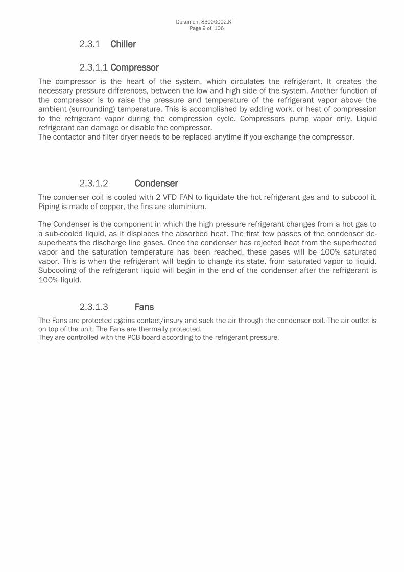
2.3.1.1 Compressor
The compressor is the heart of the system, which circulates the refrigerant. It creates thenecessary pressure differences, between the low and high side of the system. Another function ofthe compressor is to raise the pressure and temperature of the refrigerant vapor above theambient (surrounding) temperature. This is accomplished by adding work, or heat of compressionto the refrigerant vapor during the compression cycle. Compressors pump vapor only. Liquidrefrigerant can damage or disable the compressor. The contactor and filter dryer needs to be replaced anytime if you exchange the compressor.
2.3.1.2 Condenser
The condenser coil is cooled with 2 VFD FAN to liquidate the hot refrigerant gas and to subcool it.Piping is made of copper, the fins are aluminium.
The Condenser is the component in which the high pressure refrigerant changes from a hot gas toa sub-cooled liquid, as it displaces the absorbed heat. The first few passes of the condenser de-superheats the discharge line gases. Once the condenser has rejected heat from the superheatedvapor and the saturation temperature has been reached, these gases will be 100% saturatedvapor. This is when the refrigerant will begin to change its state, from saturated vapor to liquid.Subcooling of the refrigerant liquid will begin in the end of the condenser after the refrigerant is100% liquid.
2.3.1.3 FansThe Fans are protected agains contact/insury and suck the air through the condenser coil. The air outlet ison top of the unit. The Fans are thermally protected. They are controlled with the PCB board according to the refrigerant pressure.
Dokument 83000002.KfPage 10 of 106
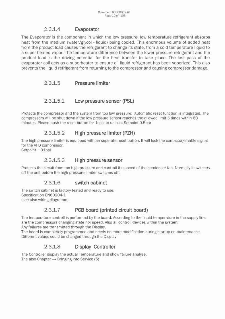
2.3.1.4 Evaporator
The Evaporator is the component in which the low pressure, low temperature refrigerant absorbsheat from the medium (water/glycol - liquid) being cooled. This enormous volume of added heatfrom the product load causes the refrigerant to change its state, from a cold temperature liquid toa super-heated vapor. The temperature difference between the lower pressure refrigerant and theproduct load is the driving potential for the heat transfer to take place. The last pass of theevaporator coil acts as a superheater to ensure all liquid refrigerant has been vaporized. This alsoprevents the liquid refrigerant from returning to the compressor and causing compressor damage.
2.3.1.5 Pressure limiter
2.3.1.5.1 Low pressure sensor (PSL)
Protects the compressor and the system from too low pressure. Automatic reset function is integrated. The compressors will be shut down if the low pressure sensor reaches the allowed limit 3 times within 60 minutes. Please push the reset button for 1sec. to unlock. Setpoint 0.5bar
2.3.1.5.2 High pressure limiter (PZH)The high pressure limiter is equipped with an seperate reset button. It will lock the contactor/enable signal for the VFD compressor.Setpoint ~ 31bar
2.3.1.5.3 High pressure sensor Protects the circuit from too high pressure and controll the speed of the condenser fan. Normally it switchesoff the unit before the high pressure limiter switches off.
2.3.1.6 switch cabinetThe switch cabinet is factory tested and ready to use.Specification EN60204-1(see also wiring diagramm).
2.3.1.7 PCB board (printed circuit board)The temperature controll is performed by the board. According to the liquid temperature in the supply line are the compressors changing state nor speed. Also all controll devices within the system.Any failures are transmitted through the Display.The board is completely programmed and needs no more modification during startup or maintenance.Different values could be changed through the Display
2.3.1.8 Display ControllerThe Controller display the actual Temperature and show failure analyze.The also Chapter → Bringing into Service (5)

Dokument 83000002.KfPage 11 of 106
2.4 Pump
The speed controlled pump in the chiller is running 24/7. The operating point is the difference pressure at the chiller supply and return water line.The pump will be switched off in case of too low pressure in the return line or if the pressure difference atthe chiller is too low or there is a recoginzed VFD failure.
2.4.1.1 Filter ball valveFilter ball valve is installed at the chiller inlet.It has to be cleaned twice during startup and at least once per year. This can be done without loosing water.Spareparts are available.
Dokument 83000002.KfPage 12 of 106
2.5 Remaining risk-phrases
2.5.1 Electrical risk If all safety regulations are followed: None
2.5.2 Mechanical riskIf all safety regulations are followed: None
2.5.3 Chemical risk
Refrigerant gas R407C is a fluorinated greenhouse gas blend of R32 (CH2F2), R125 (CH2CF3), and R134a (CF3CH2F) in a 23/25/52 ratio by mass. Non-combustible, but toxic gases can be produced by thermal decomposition in a fire.
Do not place a open fire near the chiller
Do not smoke
2.6 Other risk
Risk of death, when the unit is inside a too small room (danger of suffocation)
If the unit is used inside the European union, you have to follow the EN378 regulations.
Also take care about the local laws!
2.6.1 Safety data for refrigerantPlease look into the attached files.

Dokument 83000002.KfPage 13 of 106
2.6.2 Safety data for Mineral oilsPlease look into the attached files.
First aidBreath
o Move victim to fresh air and let him relaxo Contact the ambulance or a doctor
Skin contacto Remove the clothingo Wash the skin with potable watero Contact the ambulance or a doctor
Eye contacto Wash the eyes with clean potable water with open eyelid for min. 10 minuteso Contact the ambulance or a doctor
Swallowo Do not throw upo flush the mouth with potable water or drinking watero Contact the ambulance or a doctor
Fire fighting measuresLow fire danger. Product burns only during a high heat input.
Toxic gases can be produced by thermal decomposition in a fire.
Safety regulation during fire fighting:o Wear a self-contained breathing apparatus and fire safety clothes
Safetyo Protect your environment from Oilo Use sand or dry earth to absorb the oilo Fill this mixture in a seperate and closed container o Clean the rest with a damp cloth
In any case of oil loss to the environment contact your local fire department or the next policestation!

Dokument 83000002.KfPage 14 of 106
Handling and storage
Handlingo Avoid skin contacto Don´t breath burned oil or oil dust
Storage o storage only in provided containerso Don´t open new drum´so separate
Storage temperature: -40 till +60°Cmax. Storage time:
Original closed - limitlessafter opening - same day
Personel protection
Wear eye protection!
Wear gloves!
Wear protective clothing!

Dokument 83000002.KfPage 15 of 106
3 Definition
Attention!
The system have to be de-energized before opening!
Danger HOT!
Danger COLD!
Attention, risk of electrical shock!
Risk of snag on sharp fins and may other metal parts inside the units!
Wear eye protection!
Wear gloves!
Wear protective clothing!
Dokument 83000002.KfPage 16 of 106
4 Check before installationCheck the chiller for any transport damage!
Check system guideline of connected System to prevent from installing issues.Do not use old pipes with unknown old liquids or anything else inside.
The max. allowed Pressure at the water inlet side is 2.9bar.The max. allowed Pressure at the discharge side is 8bar.
4.1 Transport and StorageThe chiller can be moved by crane or forklift. Check out the balance point at the wooden crate packing.Transport notice → see next page!
Transport on company premises may be done with a forklift truck. The appliance must however be kept inan upright position and on no account tipped to the side. A visual inspection should be made on delivery tocheck for any damage. Complaints should be made immediately to the haulage contractor and theinsurance company must be notified at once.
Please ensure that the housing is not subjected to pressure at the sides.
Place the lifting tubes in the holes in the feet at the base of the chiller. Lock the ends of the tubes inposition with locking pins and split pins as shown.
The capacity of the lifting gear must be adequate to lift the load of chiller and may packaging.
Check the weight of the chiller units, the capacity of the lifting gear and ropes and the condition andsuitability of the aforementioned equipment.
Weight and dimensions of the unit → see Technical Data
All Pictures act as example and do not show all details of your delivered unit.
Picture act as example. Dimension is correct.

Dokument 83000002.KfPage 17 of 106

Dokument 83000002.KfPage 18 of 106
Don´t tip the chiller to the side!
4.2 Safety regulating before use!Use the medixX-Chiller only outside. Do not build a roof above the chiller.Do not use the medixX-Chiller inside
Do not place a open fire near the chiller
Do not smoke
4.3 Unpacking
Plastic or metall packing straps can be dangerous and jump up during cutting!
A damaged chiller during unpacking, is no part of the warranty! Therefore, please be careful!
4.4 Disposal of packing wasteThe IPPC-Standard wooden box can be recycled.Also all plastic and styrofoam.

Dokument 83000002.KfPage 19 of 106
4.5 Checklist before and during installationo Check the typical ambient temperature in your area according to the chiller Spec. o The chiller shall be placed on a body reference plan basement. See also Spec. For chiller weight.o There shall be at least 1m space around the chiller to all sideso Place the chiller where the fresh air intake is not blocked o KKT chillers can not provide Hurricane safety instructions for this unit. Please find another place.o Piping between customer system and chiller shall be stainless steel, copper or plastic.o See also install instructionso Piping diameter shall be at least 2“. o Install the chiller piping vibration-coshioned and static unencumbered.o Install automatic air vents after each vertical run in supply and return pipe.
Risk of snag on sharp fins and may other metal parts inside the units!

Dokument 83000002.KfPage 20 of 106

Dokument 83000002.KfPage 21 of 106

Dokument 83000002.KfPage 22 of 106
4.5.1 Installation
4.5.2 Piping connections
Attention: - Warranty regulation!
When connecting piping at the chiller take caution to stabilize the chillers connections to prevent the breaking of manufacturers seals; this can be done utilizing a second wrench to grip and secure at the chillers connection point. Failure to follow manufacturers direction will result in KKT not covering any costs or damages due to leaks in the piping at these connecting points.
Sludge accumulation will occur when using iron pipes!
Use only plastic, stainles steel or copper pipes
The provided piping connection at the chiller is 2“. Could be necessary to increase piping directly at thechiller!
Please contact KKT chiller Service for further [email protected]
Recommended minimum Piping dimensions:Anyway is the max. recommended pressure loss one way 0.2bar
medixX 50minimum piping diameter 1.5“ up to 45meter include 12 long radius ellbows each way
medixX 60minimum piping diameter 2“ up to 45meter include 12 long radius ellbows each way
medixX 70minimum piping diameter 2“ up to 45meter include 12 long radius ellbows each way
For distances exceeding 45meters (148ft.) of straight pipe, e-mail the actual pipe lenght, the difference inheigh and the required amount of elbows to KKT chillers.
Dokument 83000002.KfPage 23 of 106
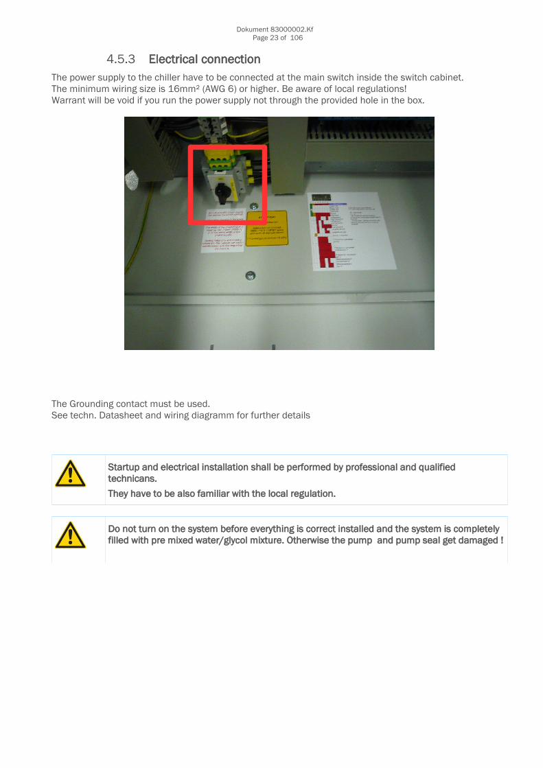
4.5.3 Electrical connection The power supply to the chiller have to be connected at the main switch inside the switch cabinet.The minimum wiring size is 16mm² (AWG 6) or higher. Be aware of local regulations!Warrant will be void if you run the power supply not through the provided hole in the box.
The Grounding contact must be used.See techn. Datasheet and wiring diagramm for further details
Startup and electrical installation shall be performed by professional and qualified technicans.
They have to be also familiar with the local regulation.
Do not turn on the system before everything is correct installed and the system is completely filled with pre mixed water/glycol mixture. Otherwise the pump and pump seal get damaged !

Dokument 83000002.KfPage 24 of 106
4.5.4 EMC Compatibility and GroundingThis comments are compiled to help the field electrician to install the grounding of the power supply and toget a EMC Compatibility.All electrical equipment produces radio and line-born interference at various frequencies. The cables passthis on to the environment like an aerial.The basic countermeasures are isolation of the wiring of control and power components, proper groundingand shielding of cables.
A large contact area is necessary for low-impedance grounding of HF interference. The use of groundingstraps instead of cables is therefore definitely advisable.
Moreover, cable shields must beconnected with purpose-made groundclips.
The grounding surface must be highly conductive bare metal. Remove any coats of varnish and paint.
The width of the grounding wire must be min. 16mm² (AWG 6) or the same width of the power supply.The grounding must be an isolated ground and must be connected on the ground terminal (X1) in the switch cabinet. The ground resistance must be less than 5 ohm.
Metal cable conduits are not allowed for grounding.
The piping of the chiller (supply and return) have to be grounded too.
Do not share the ground wire with other devices.Always use a ground wire that complies with technical standards on electrical equipment and minimize the length of the ground wire.
When using more than one Inverter, be careful not to loop the ground wire.

Dokument 83000002.KfPage 25 of 106
4.5.5 Filling the system
Fill only 250µm filtered liquids!
Use only allowed liquids!
Use only premixed water/glycol!
The concentration has to stay in a range of min.35vol% max.38vol%
The system shall be filled at the lowest point.
Vent all pumps!
Water properties: KKT chillers
properties rangepH-value 7,5 - 9Electrical conductivity 50-500µS/cmChloride (Cl-) <50 mg/kgSulfate <50 mg/kgNitrate <100 mg/kgIron <2 mg/kgCarbonic acid <20 mg/kgManganese <1 mg/kgAmmoniac <2 mg/kgFree chloride <0,5 mg/kgSulfide <0,03 mg/kg
o The medixX-Chillers have to run with anti freeze/water mixture o Use only potable water + ethylene glycol
o Allowed antifreeze is: Antifrogen N (eg. Safeflow EG) from Clariant or DowTherm SR1 from Dow Chemical
o Forbidden antifreeze is:
propylene glycol based antifreezeautomotive antifreeze mixturespure ethylene glycol
o ATTENTION: Never mix different Type and Brand of glycol. This can cause defective pump sealsand/or blocked plate heat exchangers.

Dokument 83000002.KfPage 26 of 106
4.5.6 Static Fill pressure
An installed and working automatic Airvent in supply and return piping with a correct staticpressure will prevent most of the failures and is recommended for this system.
The system is protected by a suction pressure sensor at the inlet water pipe in front of the pump.The pump will shut down if the pressure is lower than 0.5bar - with a few seconds time delay.
Minimum allowed suction pressure during startup is delayed 5seconds.Afterwards the pump will shut down and need manual reset to restart.
Dokument 83000002.KfPage 27 of 106
4.5.7 Draining air from the unit
Follow the procedure to properly air vent the chiller and Piping before start-up or after any major hydraulics repair.
1) Open all individual (not the fill or drain valves) unit valves to assure circulation.Also open all valves on the customer side.
2) Fill system with premixed water/ethylene glycol (35-38%glycol), from the lowest point.
3) The static pressure at the chiller gauge (pump is OFF) shall have the following value:Chiller same level or above the customer system ~ 0,9barChiller lower than the customer system ~ 0,3 – 1,5bar
4) Vent all air by the automatic air vent (black or brass coloured small tank on the top of the discharge side of pump and in the piping.
5) If static pressure decreases during air vent the water circuit must be refilled with premixed water/ethylene glycol (35-38%glycol) up to: see point 3
6) Now bleed all air out of the system and chiller again (expansion tank, pump, automatic and manual air bleeder). If the static pressure decreases again → refill according to point 3
7) If all air is bled out of the system start pump for a few minutes. Then switch off the pump and vent air again. If the static pressure decreases again → refill according to point 3
8) Now start pump again. Monitor pump and bleed points to insure all trapped air is removed.
9) Check pressure on suction side of the pump after a few minutes and again after a few hours and refill the system if necessary up to: → refill according to point 3
10) For a proper adjustment of the suction pressure it is necessary to have the right pressure of nitrogen filling in the expansion tank. The correct pressure of the nitrogen filling is 0,6-0,8bar. This can only be tested while the expansion tank is not under pressure.
11) The suction pressure should be re-checked within 24hours by someone on-site who can advise of any changes.
12) Generally it is necessary to check the suction pressure four times a year even if nothing is changed.
Dokument 83000002.KfPage 28 of 106
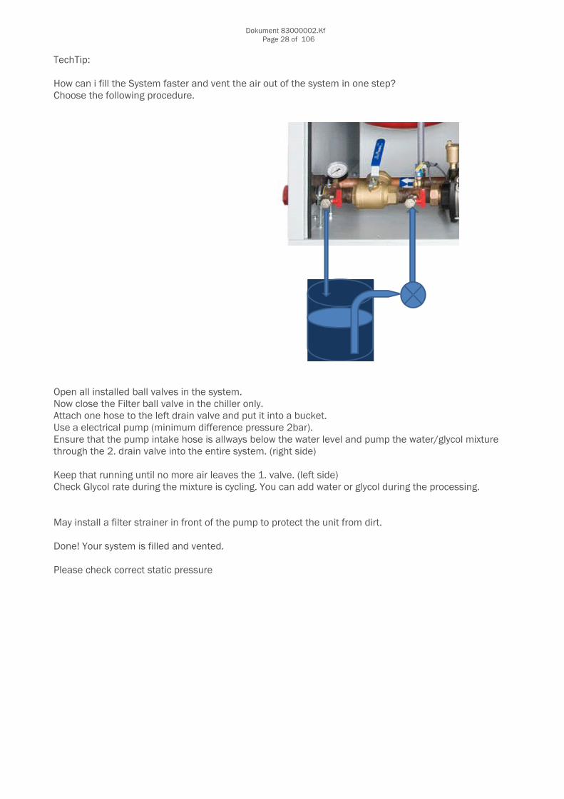
TechTip:
How can i fill the System faster and vent the air out of the system in one step?Choose the following procedure.
Open all installed ball valves in the system.Now close the Filter ball valve in the chiller only.Attach one hose to the left drain valve and put it into a bucket.Use a electrical pump (minimum difference pressure 2bar).Ensure that the pump intake hose is allways below the water level and pump the water/glycol mixture through the 2. drain valve into the entire system. (right side)
Keep that running until no more air leaves the 1. valve. (left side)Check Glycol rate during the mixture is cycling. You can add water or glycol during the processing.
May install a filter strainer in front of the pump to protect the unit from dirt.
Done! Your system is filled and vented.
Please check correct static pressure
Dokument 83000002.KfPage 29 of 106
4.5.8 Decommissioning
Placing out of operation shall be performed by professional and qualified technicans.
They have to be also familiar with the local regulation.
Disassembling has to be performed by professional and qualified technicans.
Water and refrigerant pipes are under pressure!
They have to be also familiar with the local regulation.
After the unit is relocated or longer than 2years out of operation it has to be started accordingto EN 378-2 (A – D) or to the local regulations.
4.6 DemountingAll parts (e.g. refrigerant, oil, glycol, metal, electronics, battery...) have to be recycled, re-used or disposed.Please contact your local waste management center.You could also send the unit back to KKT chillers for proper recycling.Take the local waste management regulation into account.
4.7 Re-packaging
The chiller is delivered in a throw-away pack. Don't use it twice.
Dokument 83000002.KfPage 30 of 106
5 Instructions for use
5.1 Bringing into service(1) Check that all water-valves at the chiller and piping/customer valves are complete open(2) Check that all drain and fill valves are closed(3) Ambient temperature has to be in range(4) Close all covers and switch box when ready(5) Main switch should stay at „0“ System OFF(6) Check correct power supply and phase sequence(7) Turn on the main switch to enable power supply to the unit.(8) The pump start to run automatically ( approx. 20sec. delay time)(9) The condenser fans are speed controlled and maintain ~ 20bar..in the refrigerant circuit(10) Check the correct static water pressure(11) Check the ampere rate of all electrical components
Dokument 83000002.KfPage 31 of 106
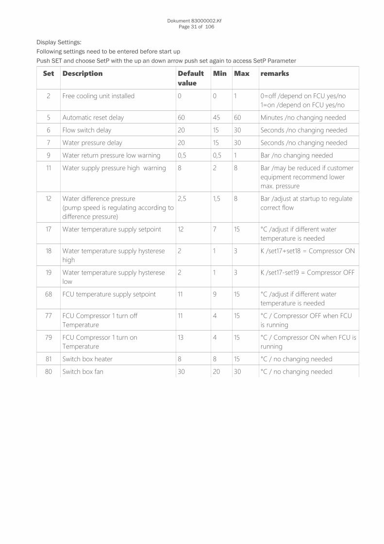
Display Settings:
Following settings need to be entered before start up
Push SET and choose SetP with the up an down arrow push set again to access SetP Parameter
Set Description Defaultvalue
Min Max remarks
2 Free cooling unit installed 0 0 1 0=off /depend on FCU yes/no1=on /depend on FCU yes/no
5 Automatic reset delay 60 45 60 Minutes /no changing needed
6 Flow switch delay 20 15 30 Seconds /no changing needed
7 Water pressure delay 20 15 30 Seconds /no changing needed
9 Water return pressure low warning 0,5 0,5 1 Bar /no changing needed
11 Water supply pressure high warning 8 2 8 Bar /may be reduced if customer equipment recommend lower max. pressure
12 Water difference pressure(pump speed is regulating according todifference pressure)
2,5 1,5 8 Bar /adjust at startup to regulate correct flow
17 Water temperature supply setpoint 12 7 15 °C /adjust if different water temperature is needed
18 Water temperature supply hysterese high
2 1 3 K /set17+set18 = Compressor ON
19 Water temperature supply hysterese low
2 1 3 K /set17-set19 = Compressor OFF
68 FCU temperature supply setpoint 11 9 15 °C /adjust if different water temperature is needed
77 FCU Compressor 1 turn off Temperature
11 4 15 °C / Compressor OFF when FCU is running
79 FCU Compressor 1 turn on Temperature
13 4 15 °C / Compressor ON when FCU isrunning
81 Switch box heater 8 8 15 °C / no changing needed
80 Switch box fan 30 20 30 °C / no changing needed

Dokument 83000002.KfPage 32 of 106
Set Description Defaultvalue
Min Max remarks
ATTENTION 24h clock Correct time/date setting will allow to timestamp error code
93 Set minutes 0 0 59
94 Set hour 0 0 23
95 Set day 1 1 31
96 Set month 1 1 12
97 Set year (2012=12,2013=13) 12 12 99
98 Set weekday (1=monday, 2=tuesday.........)
1 1 7

Dokument 83000002.KfPage 33 of 106
5.1.1 General function of the controlDescription of the control unit of the medixX-chiller:
General
Power SupplyThe Power Supply is monitored by a phase sequence relay.The phase sequence relay switches the Chiller off in case of one or more phases are lost.The phase sequence relay switches the Chiller off if the phase rotation is wrong.
If the phase sequence is correct or the phases are back the chiller starts automatically.
Temperature and Pressure SensorsAll Temperature and Pressure Sensors are monitored. Broken wire or short circuit.
Chiller
When the chiller is connected to the power supply and the main switch is “ON” the Chiller starts automatically.The Chiller Software is programmed and the settings are fixed for autonomous run.For the several control circuits see the captures below.
Display
1. Collective Failure at Display
2. LED-Status at DisplayLED 1: Compressor 1 (LED ON = Compressor RUN)LED 2: Compressor 2 (LED ON = Compressor RUN)LED 3: Fan 1&2 (LED ON = Fan RUN)LED 4: Pump (LED ON = Pump RUN)LED 5: FCU-Option (LED ON = FCU RUN)LED 6: Error AI (LED ON = Temperature or pressure Sensor Error)LED 7: Error DI (LED ON = DI Error e.g. motor protection tripped/Digital signal missing)
3. Snow flake Indikate cooling is ON4. Stand by indikate system is ready to run (pump is running)

Dokument 83000002.KfPage 34 of 106
Push SET and choose ST A with the up an down arrow push set again to access ST A Paramter
Parameter LevelST A
Description Expected value Remarks
dP01 Water pressure inlet 0.5 – 1.0 bar
dP02 Water temperature inlet 15-24°C
dP03 Water temperature outlet 9-13°C
dP04 Water temperature outletFCU
9-13°C If installed
dP05 Switch box/cabinet temperature
Depend: approx 5Kabove ambient temp.
dP06 Suction gas temperature 16-24°C
dP07 High pressure refrigerant circuit
20bar or higher
dP08 Low pressure refrigerant circuit
4-6bar
dP09 Water pressure outlet 3-8bar
dP10 Ambient temperature FCU
If installed
dP11 0-10V Compressor 1 Depend on cooling load
dP12 0-10V Fans Depend on coolingload/ambienttemperature
dP13 0-10V Pump Depend on differencepressure
dP14 0-10V FCU valve in chiller If installed
InF1 Show PCB Software Version
InF2 Show Display Software Version

Dokument 83000002.KfPage 35 of 106
Push SET and choose ST d with the up an down arrow push set again to access ST d Parameter
Parameter LevelST d
Description Remarks
ST01 Pump ON = Relay Closed = RUN
ST02 FAN 1&2 ON = Relay Closed = RUN
ST03 Compressor 1 ON = Relay Closed = RUN
ST04 Compressor 2 ON = Relay Closed = RUN
ST05 HG-Bypass ON = Relay Closed = RUN
ST06 Fan switch box ON = Relay Closed = RUN
ST07 Heater switch box ON = Relay Closed = RUN
ST08 FCU-Option enable ON = Relay Closed = RUN
ST09 Collective Fault relay ON = Relay Closed = RUN
ST10-ST32 Not used

Dokument 83000002.KfPage 36 of 106
For a optimal operation:
Pressure and On/Off control of the pump
The pump runs 24/7 after the main switch is “ON”.
The pump stops if following occurs:1. power supply off or phase sequence relay switch off, restart automatically2. emergency stop (optional, not installed at KKT)3. water temperature above 35°C more than 10min, restart with reset (see Setpoint 5)4. pressure sensor suction/discharge side pump is defective, restart with reset5. difference pressure is too low6. pressure in suction line of pump is below 0,2bar, restart with reset.
If the pressure in supply line reach ~8,0bar the pump speed decreases automatically. Attention: May some Setpoints are changed
Cooling Capacity and ON/Off control of the compressor 1 and 2
The compressor 1 starts under following conditions:1. pump run2. high pressure below 28bar3. low pressure above 1,0 bar4. low pressure sensor okay5. temperature sensor suction line okay6. no emergency stop pressed7. phase sequence relay okay8. water supply temperature over 15°C (see also Setpoint)
The compressor speed is controlled by a PID-Controller to a constant water supply temperature according toyour setpoint.If the temperature sensor in the supply line in chiller is defective the temperature sensor on the returnwater pipe is used. (result: higher temp. swing)Compressor 1 switches off if the supply water temperature drops below ~ 9°C (see also Setpoint)
If the high pressure reaches 28bar the compressor speed will be reduced step by step.The cooling capacity decreases but the compressor still runs and cools the water down as much aspossible.
29.5bar: pressure sensor in liquid pipe will turn off all compressors30.5bar: pressure limiter (need manual reset) will act as safety cut off and needs manual reset at thepressure limiter (liquid line - refrigerant)
Dokument 83000002.KfPage 37 of 106
Pressure control of the refrigerant circuit
Fan 1+2 run if one compressor (1 or 2) run.The speed of the fans 1 is controlled by a PID-Controller and depends on the high pressure of therefrigerantThe speed rises up if the pressure increases.The speed ramps down if the pressure decreases.
Fan 1+2 stop if:
1. high pressure is below 20bar2. Frequency drive defective3. emergency stop4. phase sequence relay is off
Control superheat of the evaporator
The expansion valve is controlled by a PID-Controller to keep the superheat of the suction gas at 6Kelvin.
If no compressor runs the expansion valve is completely closed.The PID-Controller for the expansion valve runs if one compressor runs.
If the superheat is below 3K or above 15K for 60sec. 3 times in one hour then the compressors shut downand an error message will be displayed at the display.
Control of the Hotgas-Bypass-Valve
The Hotgas-Bypass-Valve is NC (normally closed).If Compressor 1 or Compressor 2 starts the Hotgas-Bypass-Valve is energized for 20sec.This function is for start help. (red. Ampera rate at the compressor and protect from high pressure atstartup during warm summer conditions)If the last compressor turns off, the Hotgas-Bypass-Valve is energized for 4sec.This function is for pressure balance.
The Solenoid valve will be also energized if the output Signal to Compressor1 (0-10V) drops below 1Volt.The Valve will be de-energized when the signal reaches more than 5Volt.

Dokument 83000002.KfPage 38 of 106
Control of the FCU (Optional)
The Free Cooling Unit controller is already implemented in the software.FCU-Option is designed to save Energy.The Chiller runs with or without Free Cooling Unit.If the Free Cooling Unit will be installed afterwards change Setting 2The FCU tries to maintain ~11°C supply water temp.
The fan of the Free Cooling Unit (FCU) and the 3-Way-Valve works if:
1. Thermal contact of fan FCU is okay2. Motor protection of fan FCU is okay3. Ambient temperature is below ~5°C for more than 20sec.
The fan runs 100% all the time if above terms are given.The 3-way-valve is controlled by a PID-Controller.The 3-way-valve ties to mix the water to 11°C in the return line to the evaporator.
The fan will stop if:
1. ambient temperature is below -25°C2. Motor protection drip3. temperature sensor ambient, return chiller or sensor behind the 3-way-valve is defective4. temperature sensor after the 3-way-valve is higher then the temperature sensor return chiller.
Reason: In this case the FCU is heating and not cooling.
Dynamic adaptation of the hysteresis
The minimum input limit for the cold water outlet is limited to 9.0 ° C.
The hysteresis is still within the limits of 1.0 - 3.0 Kelvin entered.The dynamic adaptation of the hysteresis ensures that the outlet temperature does not fall below the value of 8.0 ° C.
- If the outlet temperature setpoint is less than 11.0 ° C, the maximum hysteresis can be set to the difference between the setpoint and 8.0 ° C.
- If the setpoint is reduced, the hysteresis is automatically reduced so that the switch-off point of 8.0° C is not undershot.
Dokument 83000002.KfPage 39 of 106
5.2 Unexpected situation
5.2.1 Emergency stop of control circuit (remote off)Your on-site installed emergency stop can be connected at clamp: X4 17/18 (remove the jumper)Emergency stop button shall be purchased seperate and is no equipment in the chiller.This Emergency function is more or less a control circuit break. It will not remove the power supply from theparts.Main voltage is still present at all VFD´s/Contactors/Fuses/Mainswitch........
5.2.2 Procedure after an unexpected chiller offo Reset at the switch box for 2sec.o If the system doesn`t start, check the 8BIT LED´s at the PCB board or error code at the Displayo Call KKT Service if needed
5.2.3 Procedure after high pressure faulto Ambient temperature in range? (see techn. data)o Check free air flow through the condenser coilo Clean Condenser coilo Reset at high pressure limiter o Push the reset button at the switch box for 2sec.o Call KKT service if needed
5.2.4 In case of an emergency/fireSee safety data sheet for oil/refrigerant/glycol

Dokument 83000002.KfPage 40 of 106
5.3 Signals at the PCB1. The left marked field are the 8Bit-LED´s and show any failure in the system.2. The single yellow LED in the right marked field signals a running processor. (LED pulse)2a. The yellow LED in the right marked field is cycling when the communication to the Display is OK4. Chiller can run without SD-Card but can´t log datafiles
5.3.1 Collective fault / Customer Contact
This contact can be used by any customer for their system.See wiring diagram......terminal DO5 P1, P2 and P3.
Maximum 24V AC/DC 100mA1-2 closed = RUN everything OK no Error1-3 closed = FAULT

Dokument 83000002.KfPage 41 of 106
5.3.2 Safety first – Personell protectionThis unit is produced, constructed and tested to run safety if it is installed and repaired according to this manual and the local regulations.
Because of this please read this user manual carefully and completely.This unit contains electrical parts who work with high voltage and moving parts e.g. Fans, pump, compressors.Turn off the power supply before access the unit.Only qualified service technicans shall perform start-up, maintenance and repairs.
General
Most accidents happens because of carelessness and none safety background.Most accidents would be prevented if risk identified soon enough.
The owner of this unit is responsible that everyone who is working on the unit observes the safety rules, reads the whole manual and understands it. A wrong or sloppy maintained unit could cause high body risk or even risk of death.
Don´t run this equipment under potentially explosive atmosphere.
Safety during operating
The chiller is fully automatically operating.It is prohibited to remove/change any safety and protective gear nor the installed insulating materials.The switch box stays closed and shall not be opened without any reason. Only for Service, measurement or repair.

Dokument 83000002.KfPage 42 of 106
6 Keep in service and cleaning
Only qualified mechanics are allowed to work on the system!
The system have to be de-energized before opening!
Wear eye protection!
Wear gloves!
Wear protective clothing!

Dokument 83000002.KfPage 43 of 106
6.1 Safety regulating during Maintenance and Service
Only qualified mechanics are allowed to work on the system!
Non insulated parts could be hot or cold even if the chiller is switched off.
Do not dispose any liquid in canalization or burn combustible waste.This product and all parts should be disposed of as controlled waste.
Use only original spareparts provided by KKT chillers.
Refill only the type of refrigerant displayed at the nameplate
The saftey regulations according to this manual have to be followed.Temperature nor pressure sensors and gauges have to be exchanged if they are out of range.Keep the unit clean at any time. Cover all opened piping or parts within the system during Service andMaintenance to protect from dust and moisture. Welding near oil and other flammable liquids and parts areprohibited. Welding on pressure vessels is highly prohibited!
6.2 Clean the condenserTo prevent the system from too high pressure, please clean the condenser coil at least twice per year ormore often if necessary.This could be performed with water or a brush. Attention: The fins are very thin and could be bend!
Risk of snag on sharp fins and may other metal parts inside the units!

Dokument 83000002.KfPage 44 of 106
6.3 Keep in service and cleaning - performed by qualified technicians
Undertakings operating refrigeration, air conditioning or heat pump equipment, or fire protection systems, including their circuits, which contain controlled substances shall ensure that the stationary equipment or systems: (a) with a fluid charge of 3kg or more of controlled substances are checked for leakage at least once every 12 months; this shall not apply to equipment with hermetically sealed systems, which are labelled as such and contain less than 6kg of controlled substances;(b) with a fluid charge of 30kg or more of controlled substances are checked for leakage at least once every 6 months;(c) with a fluid charge of 300kg or more of controlled substances are checked for leakage at least once every 3 months;and that any detected leakage is repaired as soon as possible and in any event within 14 days.
Service and Maintenance shall be provided by KKT or qualified service technican:o Check all safety devices according to EN 378-2 and VDMA24186 or local lawso Check for any refrigerant leak, also inside of heat exchangerso Check all heat exchangerso Check that all safety, control, measurement and alarmsystems work and are operating
correctly.o Check glycol rate o Check for any leak
SEE ALSO NEXT PAGES FOR DETAILED CHECKLIST
After the unit is relocated or longer than 2years out of operation it have to be started accordingto EN 378-2 (A – D) or to the local regulations..All exchanged parts (e.g. dryer, refrigerant, liquids, electronics, battery.....) have to be recycled.
Attention:If any compressor is changed because of burned winding, an oil test should be performed.In case of acid, exchange the oil and refrigerant. Also install a suction line filter dryer plusexchange the liquid filter dryer also.
The mandatory inspection schedules according to BGV A3 shall be performed dependence to the electrical equipment.

Dokument 83000002.KfPage 45 of 106
Service/Maintenance/Startup Checklist
No: Description Yearlycheck
6monthcheck
If needed
remarks
Compressor
1 Check for dirt and corrosion x x
2 check mounting parts and noise x
3 measure suction pressure x
4 measure suction gas temperature x
5 measure discharge temperature x
6 check oil level x
7 ckeck acid in oil x
8 exchange oil x
9 check crankcase heater function x
10 check hotgas bypass valve function x
11 check for any leak x
Air cooled condenser
20 Check for dirt and corrosion x x
21 measure condensing temperature x
22 measure subcooling x
23 measure inlet/outlet temperature x
24 check function of condensing pressure control x
25 check for any leak x
Evaporator
30 Check for dirt and corrosion x
31 measure/check superheat x
32 measure inlet/outlet temperature at evaporator x
33 measure glycol level x

Dokument 83000002.KfPage 46 of 106
No: Description Yearlycheck
6monthcheck
If needed
remarks
Parts in refrigerant and water circuit
40 Check for dirt and corrosion x x
41 check insulation x
42 check filter dryer x
43 exchange filter dryer x
44 check sight glass x
45 check all pipes for leak and corrosion x
46 check sight glass indicator x
Fans
50 Check for dirt and corrosion x x
51 check mounting parts and noise x
52 check power inlet to the fan, liquid tight strain relief x
Pump and Piping
60 Check for dirt and corrosion x
61 check mounting parts and noise x
62 check function and safety parts of pump x
63 check for any leak x x
64 check pressure difference control x
Strainer
70 Check for dirt and corrosion x x
71 clean inlet x x
72 check inlet for any damage x
Dokument 83000002.KfPage 47 of 106
No: Description Yearlycheck
6monthcheck
If needed
remarks
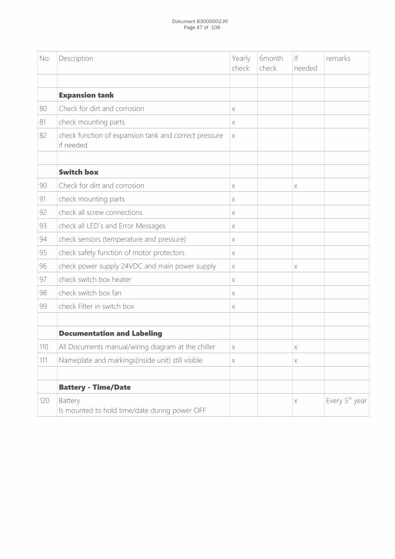
Expansion tank
80 Check for dirt and corrosion x
81 check mounting parts x
82 check function of expansion tank and correct pressure if needed
x
Switch box
90 Check for dirt and corrosion x x
91 check mounting parts x
92 check all screw connections x
93 check all LED´s and Error Messages x
94 check sensors (temperature and pressure) x
95 check safety function of motor protectors x
96 check power supply 24VDC and main power supply x x
97 check switch box heater x
98 check switch box fan x
99 check Filter in switch box x
Documentation and Labeling
110 All Documents manual/wiring diagram at the chiller x x
111 Nameplate and markings(inside unit) still visible x x
Battery - Time/Date
120 BatteryIs mounted to hold time/date during power OFF
x Every 5th year

Dokument 83000002.KfPage 48 of 106
6.4 System log guidelinesThe owner or operator have to place the system logfile in written paper or digital on a computer near thechiller and keep it available for the service technicians.This file has to be kept updated!
These include the following information:o Who, When Whato Full data of all performed work: Service, Maintenance and repairo After service, type and amount of (new, used or recycled) used/refilled or recovered refrigerant. o System log have to be updated if any analyzed refrigerant is usedo Source of pre-used refrigerant o What parts are changed or replacedo Result of all testingso non-operating periods
This page have to be carried out by the operator and placed visible close to the chiller!Responsibility for the system
Name
Street
Zip Code/Town
Phone
Fire departmentStreet
Zip Code/Town
Phone
PoliceStreet
Zip Code/Town
Phone
HospitalStreet
Zip Code/Town
Phone
Center for burned injury victimsStreet
Zip Code/Town
In case of any emergency turn off the power supply!
Dokument 83000002.KfPage 49 of 106
7 Fault analysis and Maintenance/Service
All work have to be performed by qualified technicans. Observ the local safety rules.

83000002.Kf medixX 50 - 70 Manual_GB.odtPage 50 of 106

Dokument 83000002.KfPage 51 of 106
8 Options 8.1 FCU – Free Cooling Unit
Typ FCU
Produce.-No.: FCU 00 / / xx / xxxx ← see nameplate
Year of Manufacturing 20xx ← see nameplate
Manufacturer ait-deutschland GmbH Industriestraße 395359 Kasendorf GermanyT +49 9228 9977 0F +49 9228 9977 149
Cooling capacity [kW] 5-70KW
Operating liquid (water circuit) 62-65% potable water and35-38% Ethylene Glycol
Volume [l] 8,1
Discharge temperature [°C] 11°C
Temperature accuracy [K] +/- 1
Ambient temperature limit [°C] 5 ← FCU enabled
Air flow [m³/h] 8000
Protection classification EN 60529 IP54 [with closed housing]
Electrical connection [power supply] 380-480V / 50-60Hz [3phases + grounding]
Electrical connection [kW] 2,5
Overcurrent protection [A] 6FreeCooler needs own power supply
Controll circuit 24VDc from medixX chiller
Noise level dB(A) in 5 m distance 55
Abmessungen [mm] ca. L=1025 B=855 H=855
Weight empty / operation weight [kg] 69 / 77,6
Flow rate [m³/h] 0,5 – 8,0
Dokument 83000002.KfPage 52 of 106
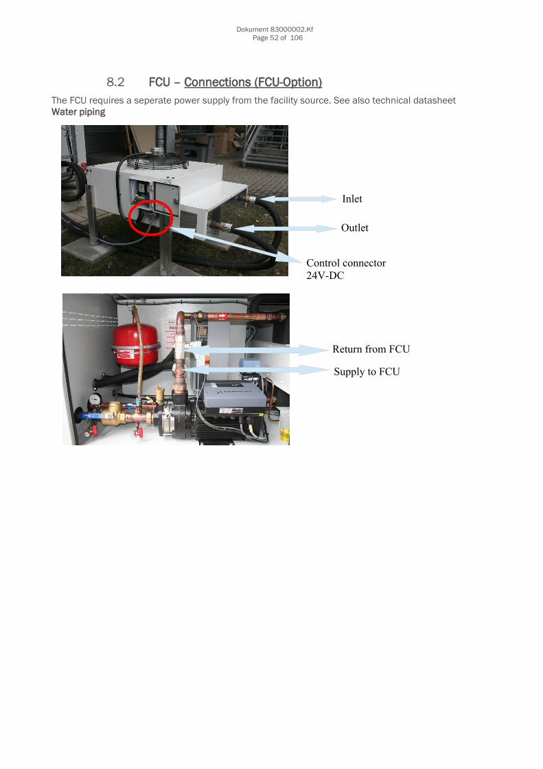
8.2 FCU – Connections (FCU-Option)The FCU requires a seperate power supply from the facility source. See also technical datasheetWater piping
Outlet
Inlet
Return from FCU
Supply to FCU
Control connector 24V-DC

Dokument 83000002.KfPage 53 of 106
3way-valveNext 2 pictures shows the Motor and Valve in OFF position! (FCU not operating - 0Volt)
Valve Characteristic Y1
Dokument 83000002.KfPage 54 of 106
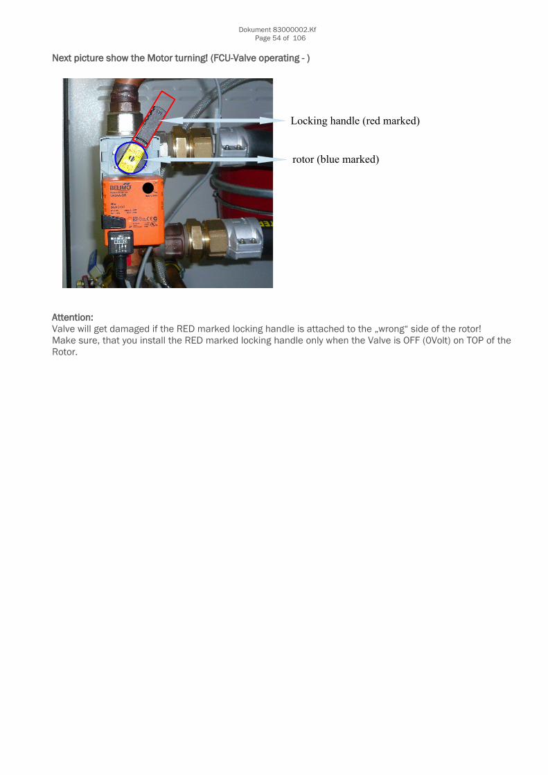
Next picture show the Motor turning! (FCU-Valve operating - )
Attention: Valve will get damaged if the RED marked locking handle is attached to the „wrong“ side of the rotor! Make sure, that you install the RED marked locking handle only when the Valve is OFF (0Volt) on TOP of theRotor.
Locking handle (red marked)
rotor (blue marked)

Dokument 83000002.KfPage 55 of 106
9 Sparepartlist
9.1 Chiller
No. Description SAPKKT-Order-No.
Remarks
1 Controller board chiller 928044
2 Fuse for compressor VTZ171, VTZ215 658363B01 3pieces
3 Overload switch compressor MTZ64-4 61002801
3a Overload switch compressor MTZ100-4 60937301
3b Overload switch compressor MTZ144-4 67115701
3c Overload switch compressor MTZ64-9 61002801
3d Overload switch compressor MTZ100-9 60937301
3e Overload switch compressor MTZ144-9 67115701
4 Overload switch pump 60652301
5 Overload switch FAN 60912801
8 Overload switch 24VDC prim 60937001
9 Circuit breaker 24VDC sec 4A 67133201
10 Circuit breaker 24VDC sec 2A 67121801
11 Controller board fuse 315mAT 65648401 10pieces
12 Contactor compressor MTZ64-4 60936701
12a Contactor compressor MTZ100-4 60936701
12b Contactor compressor MTZ144-4 60936701
12c Contactor compressor MTZ64-9 60936701
12d Contactor compressor MTZ100-9 60936701
12e Contactor compressor MTZ144-9 60936701
16 Compressor VTZ171 without Frequency drive 66002501
16a Compressor VTZ171 incl. Frequency drive 66002401
16b Compressor VTZ215 incl. Frequency drive 60902201
17 Frequency drive for VTZ171 66002601
17a Frequency drive for VTZ215 Not available

Dokument 83000002.KfPage 56 of 106
No. Description SAPKKT-Order-No.
Remarks
18 Compressor MTZ64-4 65997201
18a Compressor MTZ100-4 65997401
18b Compressor MTZ144-4 67141501
18c Compressor MTZ64-9 n/a
18d Compressor MTZ100-9 67094201
18e Compressor MTZ144-9 n/a
19 Oil sump heater for400V/50HZ and 480V/60Hz
65999901
19a Oil sump heater for400V/60Hz
65999901
20 Chiller fan 800 EBM 928032
21 Pressure sensor 30bar(refrigerant circuit)
66058701
22 Temperature sensor chiller / Please order also swagelock screw (#651246)
65878901
23 Coil for magnetic valve 66044101
24 Plug for magnetic valve 657807B01
25 Water pump 65548401
25 Shaft seal for pump 61029201
26 Water relief valve 65453701
27 Pressure sensor 10bar(water circuit)
66058801
28 Air bleeding valve 65493301
29 Pressure vessel 40l 60671701
29a Tightening strap/Metal for 60671701 60673101
31 sieve insert for filter ball - SET 928001 KKTUSA-091954
50 cabinet fan 65800901
50a cabinet heater 657987B01
51 refrigerant filter dryer 66068601
52 High pressure limiter 66055301
53 Electronic expansion valve 65894601
54 Batterie for PCB boardshall be exchanged every 5th year
65635101
55 Display – Eliwell 928038
56 Power supply 24V DC 4.2A 60949501
57 Filter (refrigerant) 66068601

Dokument 83000002.KfPage 57 of 106
9.2 FCU
No.
Description SAPKKT-Order-No.
Remarks
70 overload switch FCU fan 65662401
71 contactor FCU fan 65656801
72 FCU fan 500 65051901
73 Ambient temperature sensor / sensor chiller after 3way valve 65878901
74 actuator for 3/2-way valve FCU 65969501

Dokument 83000002.KfPage 58 of 106
10 Attachment
10.1 Piping and Instruments Diagram P&ID
German English
1 Kältekompressor Compressor
3 Verdampfer Evaporator
4 Kondensator Condenser
8 Sammler Reciever
9 Rotalock ventil Rotalock valve
10 Rückschlagventil No-return valve
15 Kugelhahn Ball valve
16 Magnetventil zur Leistunsregulierung Solenoid valve for hotgasbypass power regulation
17 Expansionsventil Expansion valve
18 Schraderventil/Klappenabsperrventil Schrader valve/Shut off valve with cap
31 Schauglas Sight glass
32 Trockner Dryer
37 Manometer Pressure gauge
38 Niederdruckpressostat Low pressure switch
39 Hochdruckpressostat High pressure switch
44 Druckaufnehmer Pressure sensor
45 Ölsumpfheizung Crank case heater
101 Pumpe Pump
104 Ausdehnungsgefäß Expansion tank
108 Sicherheitsventil Safety valve
117 3/2 Wege-Mischer mit Motor 3/2 way valve with motor
122 Filterkugelhahn Filter ball valve
128 Entleerhahn Drain valve
134 Aussentemperaturfühler Ambient temperature sensor
137 Strömungswächter Flow switch
138 Temperaturfühler Temperature sensor
141 Automatische Entlüftung Automatic air bleeder
173 Isolierung Insulation
258 Druckaufnehmer Pressure sensor

83000002.Kf medixX 50 - 70 Manual_GB.odtPage 59 of 106

11 Automatic Airvent (shall be cleaned once per year)

Dokument 83000002.KfPage 61 of 106
12 FANS
Attention, automatic restart!• The fan may switch on and off automatically for functional reasons.• After power failure or mains disconnection an automatic restart of the fan takes
place after voltage return.• Wait for the fan to come to a complete standstill before approaching it.
For more information browse your CD
13 Compressor 1 (speed controlled)
Operating voltage and cycle rate Operating voltage range The operating voltage limits are directly managed by the CD302 frequency converter generating a constant U/f ratio equal to the one of the motor design and factory preset in the inverter.
Cycle rate limit There may be no more than 12 starts per hour. A higher number reduces the service life of the motor-compressor unit. If necessary, use an anti-shortcycle timer in the control circuit.A time-out of five minutes is recommended. The system must be designed in such a way to guarantee a minimum compressor running time in order to provide proper oil return and sufficient motor cooling after starting. Note that the oil return rate varies as a function of the system design. Note: when using “process loop” control with the frequency converterthese control operations are factory preset in the CD302 on “Smart Logic Control” section.Parameter 13.00 has to be set at ON then:

Dokument 83000002.KfPage 62 of 106
13.1 VFD-Drive for Compressor 1The VFD is delivered and setup to run automatically.NO changing can be done.
Indicator lights (LEDs)If certain threshold values are exceeded, the alarm and/or warning LED lights up. A status and alarm text appear on the control panel.The ON is activated when the frequency converter receives mains voltage.. Green LED/ON: Control section is working.. Yellow Warn.: Indicates a warning.. Flashing Red Alarm: Indicates an alarm.
Change Language0-01 LanguageOption:*English (ENGLISH) [0]German (DEUTSCH) [1]French (FRANCAIS) [2]Danish (DANSK) [3]Spanish (ESPANOL) [4]Italian (ITALIANO) [5]Defines the language to be used in display.
[Quick Menu] allows quick access to different Quick Menus such as: *01 - My Personal Menu 02 - Quick Set-up 03 – PID Process Loop 04 - Changes Made 05 – Loggings
Any changes are prohibited and password protected by KKT chillers!
*See also additional Datasheet on this CD

Dokument 83000002.KfPage 63 of 106
14 Possible pump failures
Warning! Before removing the terminal box cover, make sure that the electricity supply has beenswitched off. The pumped liquid may be scalding hot and under high pressure. Before any removalor dismantling of the pump, the system must therefore be drained, or the isolating valves oneither side of the pump must be closed and the chiller pressure removed (water pipes)
– power supply out of range
– inlet pressure too lowpressure
– supply pressure too high
– pressure sensor in water circuit defective
– temperature in water circuit too high
– differential pressure not reached
– VFD defective
– Ampere rate too high

Dokument 83000002.KfPage 64 of 106
–
CME10-3
For more Information see Grundfos page or contact KKT chillers.A installed and working automatic air vent in supply & return piping with a correct static pressurewill determin most of the failures and is recommended for this system.

Dokument 83000002.KfPage 65 of 106
15 3-way valve for FCU (0-10VDC)
Dokument 83000002.KfPage 66 of 106

Dokument 83000002.KfPage 67 of 106

Dokument 83000002.KfPage 68 of 106
Dokument 83000002.KfPage 69 of 106
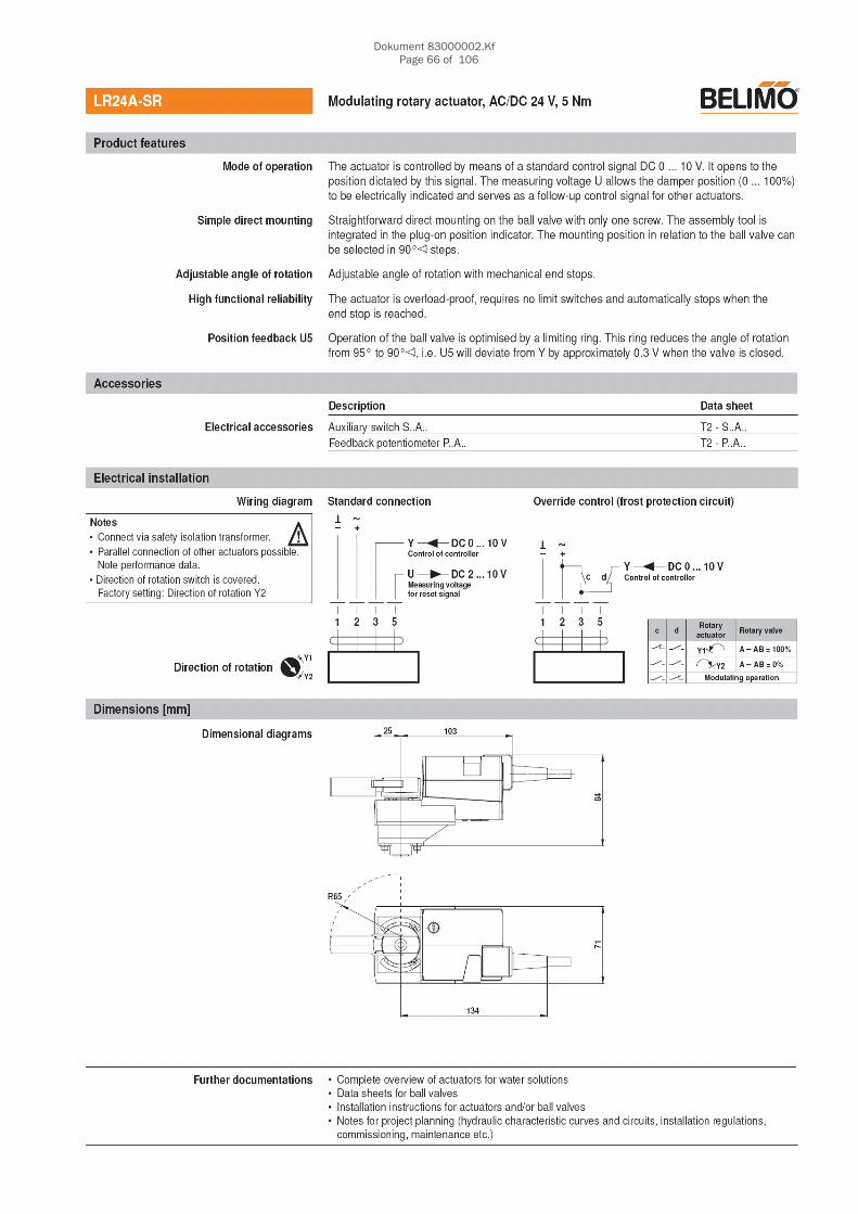
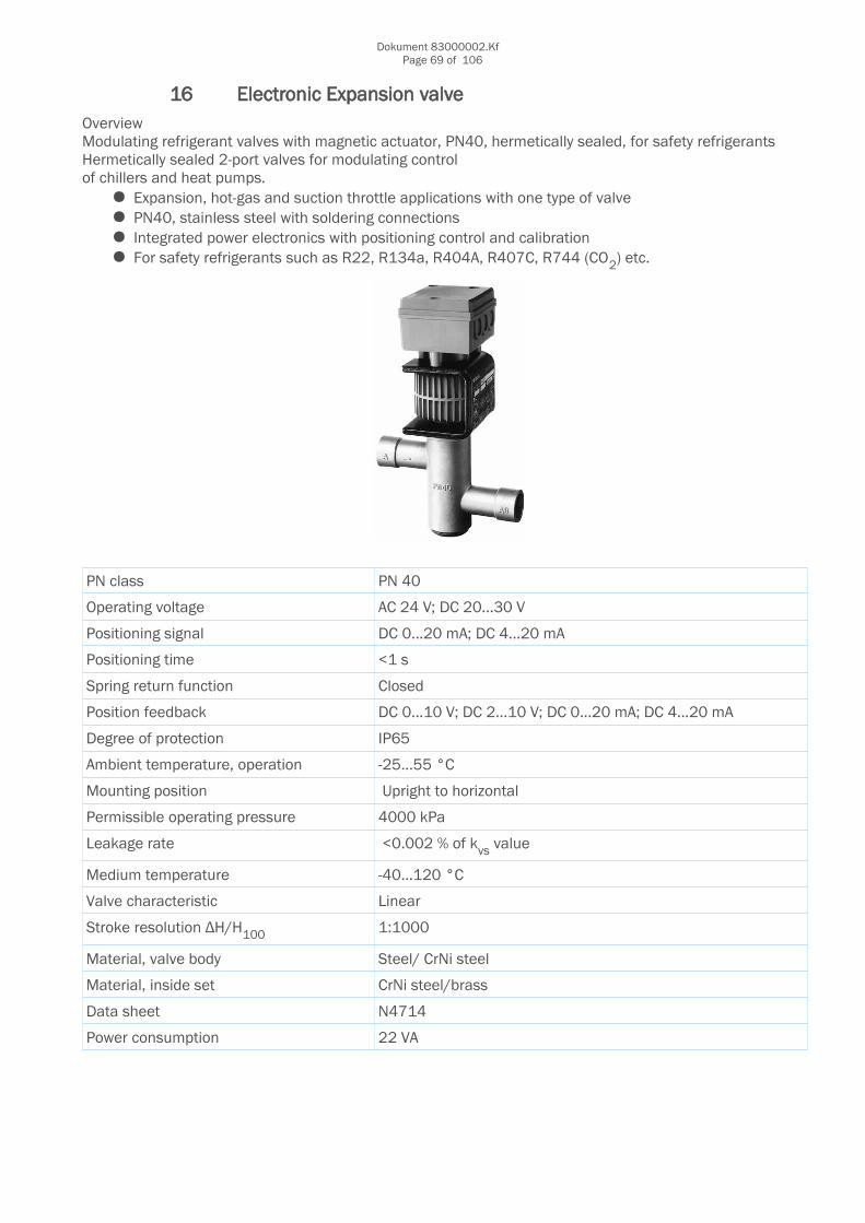
16 Electronic Expansion valveOverview Modulating refrigerant valves with magnetic actuator, PN40, hermetically sealed, for safety refrigerantsHermetically sealed 2-port valves for modulating controlof chillers and heat pumps.
Expansion, hot-gas and suction throttle applications with one type of valve PN40, stainless steel with soldering connections Integrated power electronics with positioning control and calibration For safety refrigerants such as R22, R134a, R404A, R407C, R744 (CO2) etc.
PN class PN 40
Operating voltage AC 24 V; DC 20...30 V
Positioning signal DC 0...20 mA; DC 4...20 mA
Positioning time <1 s
Spring return function Closed
Position feedback DC 0...10 V; DC 2...10 V; DC 0...20 mA; DC 4...20 mA
Degree of protection IP65
Ambient temperature, operation -25...55 °C
Mounting position Upright to horizontal
Permissible operating pressure 4000 kPa
Leakage rate <0.002 % of kvs value
Medium temperature -40…120 °C
Valve characteristic Linear
Stroke resolution ΔH/H100 1:1000
Material, valve body Steel/ CrNi steel
Material, inside set CrNi steel/brass
Data sheet N4714
Power consumption 22 VA

Dokument 83000002.KfPage 70 of 106
17 8-Bit-Failure code on PCB board
Green LED indicate System up and running. → NO ERRORJust add all illuminated „numbers“ together
Example Error Code 33
X X X32
X16
X8
X4
X2
X1
Example Error Code 6
X X X32
X16
X8
X4
X2
X1
Example Error Code 27
X X X32
X16
X8
X4
X2
X1
Possible Error Codes also shown at Display as Number → Alarm level

Dokument 83000002.KfPage 71 of 106
Error Code
Description TODO RESET MAY CAUSE
1 Water pressure inlet Check for loose wireor exchange sensor
Push reset button orwait for autom. reset
Sensor defective, short winding or loose connection
Attention:Temperature sensorcould be also out ofrangelimit: -25/+50°C
2 Water temperature inlet (Return)
3 Water temperature outlet (Supply)
4 Temp. After 3-way valve FreeCooler (option)
5 Cabinet temperature
6 Suctiongas sensor
7 Highpressure refrigerant
8 Lowpressure refrigerant
9 Water pressure outlet
10 Outsidetemp. FreeCooler (option)
11 Not used n/a n/a n/a
12 VFD Waterpump Error(System is OFF)
Try reset and check correct supply voltage to the unit
Push reset button orwait for autom. reset
Power issues, too high water flow, defective pump
13 Motor protection pump(System is OFF)
Try to reset or exchange the pump
Turn on motor protection relay andpush reset
Too high ampere drawing at the pump or short winding
14 Error water temperature, higherthan 30°C(System is OFF)
Reset unit Push reset Cooling does not work, cooling load too high or sensor defective
15 Error water inlet pressure0,2bar - setting(System is OFF)
Check water pressure
Push reset Leak in water circuit,air in the system, some valves closed or strainer blocked
16 Warning water inlet pressure0,5bar - setting(System is still running)
Check water pressure
Push reset Leak in water circuit,air in the system, some valves closed or strainer blocked
17 Error Flow switch(System is OFF)
Check water pressure
Push reset Leak in water circuit,air in the system, some valves closed or strainer blocked

Dokument 83000002.KfPage 72 of 106
Error Code
Description TODO RESET MAY CAUSE
18 Error high water supply pressure –pump without VFD(May only at startup or after refill)
Try to reset, reduce static pressure
Push reset Too high static pressure, closed valve or wrong setting
19 Error difference pressure in water circuit
Change setting Push reset Wrong setting, air in system, pump not working
20 Error high water supply pressure –pump with VFD(May only at startup or after refill)
Try to reset, reduce static pressure
Push reset Too high static pressure, closed valve or wrong setting
21 Error FAN1 thermal contact(system stay run)
Check loose wire Push reset Defective Fan
22 Error FAN2 thermal contact (system stay run)
Check loose wire Push reset Defective Fan
23 Warning high refrigerant pressure – 28bar(system stay run)
Check condenser and clean it
No action necessary-reset to acknowledgePush reset
Def. Fan, dirt condenser, high cooling load, too high ambient temperature or too much refrigerant in the system
24 Error/Warning high refrigerant pressure – 29bar(system stays running in emergency mode)
Compressor automatically reduces his speedsee also Code 23
No action necessary-reset to acknowledge
See Code 23
25 Error refrigerant pressure29.5bar(Active cooling is OFF)
see also Code 23 Reset switch AND push reset button
See Code 23
26 Error VFD Compressor 1 (Compressor 2 run as emergency mode)
See Error at VFD, check power supply, check OIL level
Push reset May exchange VFD and Compressor
27 Error motor protection Compressor 2
Turn motor protection back to ON, check OIL level
Push reset High Ampere drawing,
28 Warning low refrigerant pressure(Active cooling is still on)
(Refill never more than the Name plate shows) refill refrigerant, check flow of refrigerant
Automatic reset
(IF failure was notmore than 4 timesper hour present)
Refrigerant leak, TXVnot working, filterdryer blocked orreciever valve closed

Dokument 83000002.KfPage 73 of 106
Error Code
Description TODO RESET MAY CAUSE
29 Error low refrigerant pressure(Active cooling is OFF)
(Refill never more than the Name plate shows) refill refrigerant, check flow of refrigerant
Push reset Refrigerant leak, TXVnot working, filterdryer blocked orreciever valve closed
30 Error maximum suction gas temperature reached(Active cooling is off)
Refill system, check TXV, check insulationof sensor
Push reset TXV not working correctly, watertemperature too high, refrigerant leak
31 Error superheat out of rangemin. 3K / max. 15K(Active cooling is off)
See Code 30(only present if failure happens 3 times per hour)
Push reset See Code 30
32 Phase sequence relay(power supply more than 4 seconds out of range)
Check power supply Automatic reset after20 seconds
Power supply wrong or out of range
33 Error emergency Stop(System is OFF)(Attention- Emergency stop act only as control stop. Power is still present)
Check wiring or check stop button if installed
Push reset Emergency stop pressed
34 Error FreeCoolerFan thermal contact
Check loose wire, exchange FAN
Push reset Defective Fan
35 Error FreeCoolerFan motor protection relay
Turn motor protection back to ON, exchange FAN
Push reset High Ampere drawing,
36 Error FCU heating (FCU-supply is higher than FCU-inlet temperature)
Reset and wait 10 minutes
Push reset 3way valve not closing, ambient sensor defective, wrong parameter setting in Display
37 SD-Card write Error(6h Datalogger files are no longer monitored at the card)
Change SD-cardATTENTION: Use only Card provided by KKT
No action possible Wrong card installed or card corrupted
38 Error mechanical pressure switch(Active cooling is OFF)
see also Code 23 Reset switch AND push reset button
See Code 23
ErCo Error Modbus communication Check communication, check cable
No action possible Display or PCB defective

Dokument 83000002.KfPage 74 of 106
18 Filter ball valve
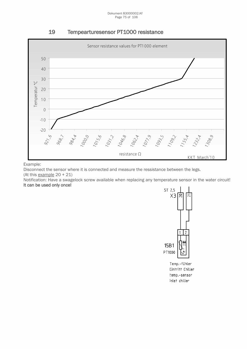
Dokument 83000002.KfPage 75 of 106
19 Tempearturesensor PT1000 resistance
Example:Disconnect the sensor where it is connected and measure the ressistance between the legs.(At this example 20 + 21)Notification: Have a swagelock screw available when replacing any temperature sensor in the water circuit!It can be used only once!
Sensor resistance values for PT1 000 element
-20
-1 0
0
1 0
20
30
40
50
resistance Ω
Tem
pera
tur °
C
K KT March´1 0
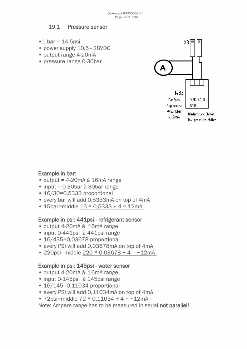
Dokument 83000002.KfPage 76 of 106
19.1 Pressure sensor
•1 bar = 14.5psi • power supply 10,5 - 28VDC• output range 4-20mA• pressure range 0-30bar
Example in bar: • output = 4-20mA à 16mA range • input = 0-30bar à 30bar range • 16/30=0,5333 proportional • every bar will add 0,5333mA on top of 4mA • 15bar=middle 15 * 0,5333 + 4 = 12mA
Example in psi: 441psi - refrigerant sensor • output 4-20mA à 16mA range • input 0-441psi à 441psi range• 16/435=0,03678 proportional • every PSI will add 0,03678mA on top of 4mA • 220psi=middle 220 * 0,03678 + 4 = ~12mA
Example in psi: 145psi - water sensor • output 4-20mA à 16mA range • input 0-145psi à 145psi range• 16/145=0,11034 proportional • every PSI will add 0,11034mA on top of 4mA • 72psi=middle 72 * 0,11034 + 4 = ~12mA Note: Ampere range has to be measured in serial not parallel!
AA

Dokument 83000002.KfPage 77 of 106
20 Pressure, Temperature and Flow chart
Pressure Temperature Flow
bar psi °C °F K m³/h l/s gpm
0 0 -25 -13 248 0,5 8 2,2
1 14,5 -20 -4 253 1 17 4,4
2 29,0 -15 5 258 1,5 25 6,6
3 43,5 -10 14 263 2 33 8,8
4 58,0 -5 23 268 2,5 42 11
5 72,5 0 32 273 3 50 13,2
6 87,0 5 41 278 3,5 58 15,4
7 101,5 10 50 283 4 67 17,6
8 116,0 15 59 288 4,5 75 19,8
9 130,5 20 68 293 5 83 22
10 145,0 25 77 298 5,5 92 24,2
11 159,5 30 86 303 6 100 26,4
12 174,0 35 95 308 6,5 108 28,6
13 188,5 40 104 313 7 117 30,8
14 203,1 45 113 318 7,5 125 33
15 217,6 50 122 323 8 133 35,2
16 232,1
17 246,6 1K ~ 1,8°F 1m³ = 1000l = 264gallon
18 261,1 1K = 1°C 10l = 2,64gallon3,78l = 1 gallon
19 275,6
20 290,1
21 304,6
22 319,1
23 333,6
24 348,1
25 362,6
26 377,1
27 391,6
28 406,1
29 420,6
30 435,1
1bar = 14.5psi

Dokument 83000002.KfPage 78 of 106
21 Safety data for Antifrogen N

Dokument 83000002.KfPage 79 of 106
Safety data sheet in accordance with 2001/58/EC ANTIFROGEN N Page 1
Substance key: SXR024717 Version : 1 - 33 / EU
Revision Date: 25.03.2004 Date of printing : 23.08.2004
1. Identification of the substance/preparation and company
Trade name ANTIFROGEN N
Use of the substance/preparation. Industry sector : Functional Fluids Type of use : Brine for refrigeration
Identification of the company Clariant GmbH
65926 Frankfurt am Main Telephone no. : +49 69 305 18000
Information about the substance/preparation Division Functional Chemicals ++49(0)69-305-2092/15315/32251
Emergency telephone number : +49 69 305 6418
2. Composition/information on ingredients
Chemical characterization Monoethylene glycol (1,2-ethane diol) with inhibitors
Hazardous ingredients
Ethanediol Concentration : 90 - 95 % CAS number : 107-21-1 EINECS number : 203-473-3 Hazard symbols Xn R phrases 22
Sodium nitrite Concentration : < 0,5 % CAS number : 7632-00-0 EINECS number : 231-555-9 Hazard symbols O T N R phrases 8 25 50
Potassium nitrite Concentration : < 0,2 % CAS number : 7758-09-0 EINECS number : 231-832-4 Hazard symbols O T N R phrases 8 25 50
3. Hazards identification Harmful if swallowed.
Safety data sheet in accordance with 2001/58/EC ANTIFROGEN N

Dokument 83000002.KfPage 80 of 106
Substance key: SXR024717 Version : 1 - 33 /EU
Revision Date: 25.03.2004 Date of printing : 23.08.2004
4. First aid measures
General information Remove soiled or soaked clothing immediately
After inhalation In the event of symptoms seek medical advice.
After contact with skin In case of contact with skin wash off immediately with plenty of water
After contact with eyes In case of contact with eyes rinse thoroughly with plenty of water and seek medical advice
After ingestion Summon a doctor immediately.
5. Fire-fighting measures Suitable extinguishing media
water spray jet alcohol-resistant foam carbon dioxide dry powder
Special hazards from the substance itself, its combustion products or from its vapours In case of fires, hazardous combustion gases are formed: Carbon monoxide (CO) Nitrous gases (NOx)
Special protective equipment for firefighting Use self-contained breathing apparatus
6. Accidental release measures Personal precautions
Ensure adequate ventilation. Wear suitable personal protective equipment.
Environmental precautions Do not allow to enter drains or waterways
Methods for cleaning up/taking up Pick up with absorbent material (eg sand, kieselgur, acid binder, universal binder, sawdust). Dispose of as prescribed
7. Handling and storage Advice on safe handling
Open and handle container with care. Provide good ventilation of working area (local exhaust ventilation if necessary).
Advice on protection against fire and explosion Observe the general rules of industrial fire protection

Dokument 83000002.KfPage 81 of 106
Safety data sheet in accordance with 2001/58/EC ANTIFROGEN N Page 3
Substance key: SXR024717 Version : 1 - 33 / EU
Revision Date: 25.03.2004 Date of printing : 23.08.2004
Advice on storage compatibility Do not store with alkalies
8. Exposure controls/personal protection Ingredients with occupational exposure limits to be monitored
ETHYLENE GLYCOL CAS number : 107-21-1 EU. Indicative Exposure and Directives relating to the protection of risks related to work exposure to chemical, physical, and biological agents. EU Exposure Limit Values Data Revision : 07 2000 Time Weighted Average (TWA): Values: 52 mg/m3 20 ppm
ETHYLENE GLYCOL CAS number : 107-21-1 EU. Indicative Exposure and Directives relating to the protection of risks related to work exposure to chemical, physical, and biological agents. EU Exposure Limit Values Data Revision : 07 2000 Skin designation: Can be absorbed through the skin.
ETHYLENE GLYCOL CAS number : 107-21-1 EU. Indicative Exposure and Directives relating to the protection of risks related to work exposure to chemical, physical, and biological agents. EU Exposure Limit Values Data Revision : 07 2000 Short Term Exposure Limit (STEL): Values: 104 mg/m3 40 ppm
General protective measures
Do not inhale vapours Avoid contact with eyes and skin
Hygiene measures Keep away from foodstuffs and beverages.
Respiratory protection : Use respiratory protection in case of insufficient exhaust ventilation or prolonged exposure Full mask to standard DIN EN 136 Filter A (organic gases and vapours) to standard DIN EN 141 The use of filter apparatus presupposes that the environment atmosphere contains at least 17% oxygen by volume, and does not exceed the maximum gas concentration, usually 0.5% by volume. Relevant guidelines to be considered include EN 136/141/143/371/372 as well as other national regulations.

Dokument 83000002.KfPage 82 of 106
Safety data sheet in accordance with 2001/58/EC ANTIFROGEN N Page 4
Substance key: SXR024717 Version : 1 - 33 / EU Revision Date: 25.03.2004 Date of printing : 23.08.2004
Hand protection :
For long-term exposure: Butyl rubber gloves Minimum breakthrough time / gloves : 480 min Minimum thickness / gloves 0,7 mm
For short-term exposure (splash protection): Nitrile rubber gloves. Minimum breakthrough time / gloves : 30 min Minimum thickness / gloves 0,4 mm
These types of protective gloves are offered by various manufacturers. Please note the manufacturers´ detailed statements, especially about the minimum thickness and the minimum breakthrough time. Consider also the particular working conditions under which the gloves are being used.
Eye protection : safety glasses
9. Physical and chemical properties
Form : Liquid
Colour : light yellow
Odour : perceptible
Pourpoint : approx. -70 °C Method : DIN 51583
Boiling temperature : approx. 170 °C ( 1.013 mbar) Method : ASTM D 1120
Flash point : approx. 120 °C Method : DIN 51758 (closed cup)
Ignition temperature : approx. 410 °C Method : DIN 51794
Oxidizing properties : Not applicable
Self-ignition temperature : not determined
Lower explosion limit : 3 %(V)
Upper explosion limit : not determined
Evaporation rate : not determined
Vapour pressure : < 0,1 mbar (20 °C) Method : Calculated by Syracuse.
Density : approx. 1,14 g/cm3 (20 °C) Method : DIN 51757
Bulk density : Not applicable
Vapour density in relation to not determined air :
Dokument 83000002.KfPage 83 of 106
Safety data sheet in accordance with 2001/58/EC ANTIFROGEN N Page 5
Substance key: SXR024717 Version : 1 - 33 / EU
Revision Date: 25.03.2004 Date of printing : 23.08.2004
Solubility in water : (20 °C) miscible in all proportions
Soluble in ... : fat not determined
pH value : 8 - 9 (20 °C, 300 g/l) Method : DIN EN 1262
Octanol/water partition Not applicable coefficient (log Pow) :
Viscosity (kinematic) : 26 - 29 mm2/s ( 20 °C) Method : DIN 51562
Combustion number : Not applicable
10. Stability and reactivity Thermal dmedixXmposition :
approx. 260 °C Method : DSC
Hazardous reactions Reactions with alkalies.
11. Toxicological information
Acute oral toxicity : LD50 4.000 mg/kg (rat) Source : IUCLID Information based on the main component.
Acute inhalation toxicity : not determined
Acute dermal toxicity : not determined
Irritant effect on skin : non-irritant
Irritant effect on eyes : slightly irritant
Sensitization : not determined
Mutagenicity : not determined
Remarks Vapours and mists cause irritation/burns to eyes and the respiratory tract There is a possibility of kidney damage Poisoning affects the central nervous system
12. medixXlogical information Biodegradability :
90 % good degradability Method : Zahn-Wellens test
Fish toxicity : LC50 1.500 mg/l (golden orfe)

Dokument 83000002.KfPage 84 of 106
Safety data sheet in accordance with 2001/58/EC ANTIFROGEN N Page 6
Substance key: SXR024717 Version : 1 - 33 / EU
Revision Date: 25.03.2004 Date of printing : 23.08.2004
Remarks If handled correctly it causes no disturbanc
e in treatment plants.
13. Disposal considerations Product In accordance with local authority regulations, take to special waste incineration plant
14. Transport information ADR ADNR RID IATA IMDG not restricted not restricted not restricted not restricted not
restricted
15. Regulatory information Labelling in accordance with EC-Directives hazard warning labelling compulsory Classification according to the calculation procedure of the Dangerous Preparations Directive (1999/45/EC). Hazard symbols Xn Harmful Hazardous component(s) to be indicated on label Ethanediol R phrases 22 Harmful if swallowed. S phrases 2 Keep out of the reach of children. 24/25 Avoid contact with skin and eyes.
16. Other information Text of the R-phrases which are allocated to the ingredients/components mentioned in section 2 of this Safety Data Sheet. 22 Harmful if swallowed. 25 Toxic if swallowed. 50 Very toxic to aquatic organisms. 8 Contact with combustible material may cause fire.

Dokument 83000002.KfPage 85 of 106
21.1 Safety data for Dowtherm SR1
Material Safety Data SheetPAGE 1 OF 8SAFETY DATA SHEET11/ 6/2004________________________________________________________________________1. IDENTIFICATION OF THE SUBSTANCE/PREPARATION AND OF THECOMPANY/UNDERTAKINGDOW CHEMICAL COMPANY LTD 2 HEATHROW BOULEVARD284 BATH ROADWEST DRAYTONMIDDLESEXUB7 0DQ24 HOUR EMERGENCY RESPONSE NUMBER : +44-1553-761-251For product information: +44-0208-917-5000Product Name: DOWTHERM* SR-1 HEAT TRANSFER FLUID, DYEDLV70: 25630 Issue Date: May 02 Ref: KE005Revised: June 04 (Section(s) 8)Use of the substance/preparationFor industrial use only.________________________________________________________________________2. COMPOSITION/INFORMATION ON INGREDIENTSInhibited glycol formulationDangerous components (see section 16 for complete R-phrases):CAS EC NoEthylene glycol >95 % Xn; R22 000107-21-1 203-473-3________________________________________________________________________3. HAZARDS IDENTIFICATIONHarmful if swallowed.________________________________________________________________________4. FIRST-AID MEASURESNever give fluids or induce vomiting if patient is unconscious or ishaving convulsions.InhalationMove person to fresh air; if effects occur, consult a physician.________________________________________________________________________* Trademark of The Dow Chemical Company.

Dokument 83000002.KfPage 86 of 106
PAGE 2 OF 8SAFETY DATA SHEET11/ 6/2004DOWTHERM* SR-1 HEAT TRANSFER FLUID, DYED________________________________________________________________________Skin ContactImmediately flush skin with water while removing contaminated clothingand shoes. Get medical attention if symptoms occur. Wash clothingbefore reuse. Destroy contaminated articles including leather itemssuch as shoes.Eye ContactFlush eyes thoroughly with water for several minutes. Remove contactlenses after initial 1-2 minutes and continue flushing for severaladditional minutes. If effects occur, consult a physician, preferablyan ophthalmologist.IngestionDo not induce vomiting. Seek medical attention immediately. If personis fully conscious give 1 glass of water. If medical advice is delayedand if an adult has swallowed several grams of chemical, then give ca.100 ml (gram) hard liquor such as 40% whisky. For children giveproportionally less liquor at a dose of 8mL (8 gram, 1.5 teaspoon) ofliquor for each 5 kg body weight or 2 mL per kg bodyweight (36 mL foran 18 kg child).Note to PhysicianIf several grammes of ethylene glycol have been ingested, earlyadministration of ethanol may counter the toxic effects (metabolicacidosis, renal damage). Consider hemodialysis or peritoneal dialysisand thiamine 100mg plus pyridoxide 50mg every 6 hours.If ethanol is used, a therapeutically effective blood concentration inthe range of 100-150 mg/dL may be achieved by a rapid loading dosefollowed by a continuous intravenous infusion. Consult standardliterature for details of treatment.4-Methyl pyrazole (Antizol (R)) is an effective blocker of alcoholdehydrogenase and should be used in the treatment of ethylene glycol,di- or triethylene glycol, ethylene glycol butyl ether, or methanolintoxication if available.Fomepizole protocol (Brent J. et al., New Eng J Med, Feb 8, 2001 344:6,p. 424-9): loading dose 15 mg/kg intravenously, follow by bolus dose of10 mg/kg every 12 hours; after 48 hours, increase bolus dose to 15mg/kg every 12 hours.Continue fomepizole until serum methanol, ethylene glycol, diethyleneglycol or triethylene glycol are undetectable. The signs and symptomsof poisoning include anion gap metabolic acidosis, central nervoussystem depression, renal tubular injury, and possible late stagecranial nerve involvement.Respiratory symptoms, including pulmonary edema, may be delayed.Persons receiving significant exposures should be observed 24-48 hoursfor signs of respiratory distress.In severe poisoning, respiratory support with mechanical ventilationand positive end expiratory pressure may be required.If lavage is performed, suggest endotracheal and/or oesophagealcontrol. Danger from lung aspiration must be weighed against toxicitywhen considering emptying the stomach.

Dokument 83000002.KfPage 87 of 106
PAGE 3 OF 8SAFETY DATA SHEET11/ 6/2004DOWTHERM* SR-1 HEAT TRANSFER FLUID, DYED________________________________________________________________________5. FIRE-FIGHTING MEASURESExtinguishing MediaWater fog or fine spray. Carbon dioxide fire extinguishers. Drychemical fire extinguishers. Foam.Do not use direct water stream. May spread fire.Alcohol resistant foams (ATC type) are preferred. General purposesynthetic foams (including AFFF) or protein foams may function, butwill be less effective.Hazardous Combustion ProductsDuring a fire, smoke may contain the original material in addition tocombustion products of varying composition which may be toxic and/ orirritating.Combustion products may include and are not limited to: Carbonmonoxide. Carbon dioxide.Protection of FirefightersWear positive-pressure self-contained breathing apparatus andprotective fire fighting clothing (includes fire fighting helmet, coat,trousers, boots and gloves). If protective equipment is not availableor not used, fight fire from a protected location or a safe distance.Specific Fire or Explosion HazardsKeep people away. Isolate fire area and deny unneccessary entry. Usewater spray to cool fire exposed containers and fire affected zoneuntil fire is out and danger of reignition has passed. Fight fire froma protected location or safe distance. Consider use of unmanned hoseholder or monitor nozzles. Immediately withdraw all personnel from areain case of rising sound from venting safety device or discolouration ofthe container. Burning liquids may be extinguished by dilution withwater. Do not use direct water stream. May spread fire. Move containersfrom fire area if this is possible without hazard. Burning liquids maybe moved by flushing with water to protect personnel and minimiseproperty damage.Other flammability informationContainer may rupture from gas generation in a fire situation. Violentsteam generation or eruption may occur upon application of direct waterstream to hot liquids. Liquid mist of this product can burn. Flammableconcentrations of vapour can accumulate at temperatures above 111deg.C.________________________________________________________________________6. ACCIDENTAL RELEASE MEASURESPersonal PrecautionsUse appropriate safety equipment. For additional information, refer toSection 8, Exposure Controls/Personal Protection.May be a slipping hazard.

Dokument 83000002.KfPage 88 of 106
PAGE 4 OF 8SAFETY DATA SHEET11/ 6/2004DOWTHERM* SR-1 HEAT TRANSFER FLUID, DYED________________________________________________________________________Environmental PrecautionsPrevent from entering into soil, ditches, sewers, waterways and/orgroundwater. See section 12, medixXlogical Information.Methods of Cleaning UpSmall spills: Absorb with materials such as:Cat litter. Sawdust. Vermiculite. Zorb-all (R).Collect in suitable and properly labelled containers.Large spills: Dike spill immediately. Contain spill if possible. SeeSection 13, Disposal Considerations, for additional information.________________________________________________________________________7. HANDLING AND STORAGEHandlingDo not swallow. See Section 8, Exposure Controls/Personal Protection.Spills of these organic liquids on hot fibrous insulations may lead tolowering of the autoignition temperatures, possibly resulting inspontaneous combustion.When performing maintenance activities, proper care should be taken toprevent spilled fluid from entering the environment. Any spilled fluidshould be absorbed and disposed of in accordance with all regulations.StorageStore in original unopened containers.Do not store in containers made of: Galvanised steel.Avoid exposure to UV-light as this can adversely affect quality.________________________________________________________________________8. EXPOSURE CONTROLS/PERSONAL PROTECTIONExposure GuidelinesEthylene glycol: The UK Health and Safety Executive has established anOccupational Exposure Standard(OES) of 10mg/m3 (8-hour TWA) forparticulate; 60mg/m3 (8-hour TWA) and 125mg/m3 (15-min STEL) forvapour.Engineering ControlsProvide general and/or local exhaust ventilation to control airbornelevels below the exposure guidelines.Personal Protective Equipment- Respiratory ProtectionAtmospheric levels should be maintained below the exposure guideline.For most conditions, no respiratory protection should be needed;however, if material is heated or sprayed, use an approved airpurifyingrespirator.Use a CE approved air-purifying respirator with cartridge/filter for:Organic vapours and particles, type AP2.

Dokument 83000002.KfPage 89 of 106
PAGE 5 OF 8SAFETY DATA SHEET11/ 6/2004DOWTHERM* SR-1 HEAT TRANSFER FLUID, DYED________________________________________________________________________- Skin ProtectionWhen prolonged or frequently repeated contact could occur, useprotective clothing chemically resistant to this material. Selection ofspecific items such as face shield, gloves, boots, apron, or full bodysuitwill depend on operation. If hands are cut or scratched, usegloves chemically resistant to this material even for brief exposures.When handling hot material, protect skin from thermal burns as well asfrom skin absorption.-Hand protectionUse chemical resistant gloves classified under standard EN 374:Protective gloves against chemicals and micro-organisms.Examples of preferred glove barrier materials include: Butyl rubber.Natural rubber ("latex"). Neoprene. Nitrile/butadiene rubber ("nitrile"or "NBR"). Polyethylene. Ethyl vinyl alcohol laminate ("EVAL").Polyvinyl alcohol ("PVA"). Polyvinyl chloride ("PVC" or "vinyl").When prolonged or frequently repeated contact may occur, a glove with aprotection class of 2 or higher (breakthrough time greater than 30minutes according to EN 374) is recommended.NOTICE: The selection of a specific glove for a particular applicationand duration of use in a workplace should also take into account allrequisite workplace factors such as, but not limited to: Otherchemicals which may be handled, physical requirements (cut/punctureprotection, dexterity, thermal protection), as well as theinstructions/specifications provided by the glove supplier.- Eye/Face ProtectionUse safety glasses. If exposure causes eye discomfort, use a full-facerespirator.________________________________________________________________________9. PHYSICAL AND CHEMICAL PROPERTIESDensity : >1.0Boiling point/range : 163 deg.CWater solubility : infiniteVapour pressure : 2.2 mmHg (20 deg.C)Specific gravity : 1.1295 (16 deg.C)Flash point : 111 deg.C (ethylene glycol) (TCC)Auto-ignition temp. : 398 deg.C (ethylene glycol)Flammability-LFL : 3.2 %vol/vol (ethylene glycol)Flammability-UFL : not determined________________________________________________________________________10. STABILITY AND REACTIVITYChemical StabilityThermally stable at recommended temperatures and pressures.Exposure to elevated temperatures can cause product to dmedixXmpose.
Dokument 83000002.KfPage 90 of 106
PAGE 6 OF 8SAFETY DATA SHEET11/ 6/2004DOWTHERM* SR-1 HEAT TRANSFER FLUID, DYED________________________________________________________________________Materials to AvoidAvoid contact with: Strong acids. Strong bases. Strong oxidisingagents.Hazardous DmedixXmposition ProductsDmedixXmposition products depend upon temperature, air supply and thepresence of other materials.DmedixXmposition products may include and are not limited to: Aldehydes.Alcohols. Ethers.Generation of gas during dmedixXmposition can cause pressure in closedsystems.Hazardous PolymerisationWill not occur.________________________________________________________________________11. TOXICOLOGICAL INFORMATIONData for: Ethylene glycol:- IngestionOral toxicity is expected to be moderate in humans even though testswith animals show a lower degree of toxicity. Excessive exposure maycause central nervous system effects, cardiopulmonary effects(metabolic acidosis) and kidney failure. Swallowing may result insevere effects, even death. The lethal dose in humans is estimated tobe 100 ml.May cause nausea or vomiting. May cause abdominal discomfort ordiarrhea.The oral LD50 for rats for a similar material is 8200 mg/kg.- Skin ContactBrief contact is essentially nonirritating to the skin. Prolongedcontact may cause slight skin irritation with local redness. May causemore severe response if skin is abraded (scratched or cut). Prolongedskin contact is unlikely to result in absorption of harmful amounts.Repeated skin exposure to large quantities may result in absorption ofharmful amounts. Massive contact with damaged skin or with materialsufficiently hot to burn skin may result in absorption of potentialylethal amounts.The LD50 for skin absorption in rabbits for similar materials is >2000mg/kg.- InhalationAt room temperature, exposure to vapour is minimal due to lowvolatility. With good ventilation, single exposure is not expected tocause adverse effects. If material is heated or areas are poorlyventilated, vapour/mist may accumulate and cause respiratory irritationand symptoms such as headache and nausea.- EyesMay cause slight temporary eye irritation. Corneal injury is unlikely.Vapour or mist may cause eye irritation.

Dokument 83000002.KfPage 91 of 106
PAGE 7 OF 8SAFETY DATA SHEET11/ 6/2004DOWTHERM* SR-1 HEAT TRANSFER FLUID, DYED________________________________________________________________________MutagenicityIn vitro genetic toxicity studies were negative. Animal genetictoxicity studies were negative.CarcinogenicityDid not cause cancer in laboratory animals.Developmental/Reproductive EffectsBased upon animal studies, ingestion of very large amounts of ethyleneglycol appears to be the major and possibly only route of exposure toproduce birth defects. Exposures by inhalation or skin contact, theprimary route of occupational exposure, had minimal effect on the fetusin animal studies.Ingestion of large amounts of ethylene glycol has been shown tointerfere with reproduction in animals. Specifically, growthretardation and decreased litter size in rats and mice and decreasingmating frequency in mice were observed.Systemic effectsRepeated excessive exposures may cause irritation of the upperrespiratory tract.In humans, effects have been reported on the following organs: Centralnervous system.Observations in humans include: Nystagmus (involuntary eye movement).In animals, effects have been reported on the following organs: Kidney.Liver.________________________________________________________________________12. medixXLOGICAL INFORMATIONMobility and Bioaccumulation PotentialBased largely or completely on information for: Ethylene glycol:Bioconcentration potential is low (BCF less than 100 or log Pow lessthan 3). Potential for mobility in soil is very high (Koc between 0 and50).DegradationBased largely or completely on information for: Ethylene glycol:Material is readily biodegradable. Passes OECD Test(s) for readybiodegradability.Aquatic ToxicityBased largely or completely on information for: Ethylene glycol:Material is not classified as dangerous to aquatic organisms(LC50/EC50/IC50 greater than 100 mg/L in most sensitive species).________________________________________________________________________13. DISPOSAL CONSIDERATIONSDo not dump into any sewers, on the ground, or into any body of water.Any disposal practice must be in compliance with all local and nationallaws and regulations.
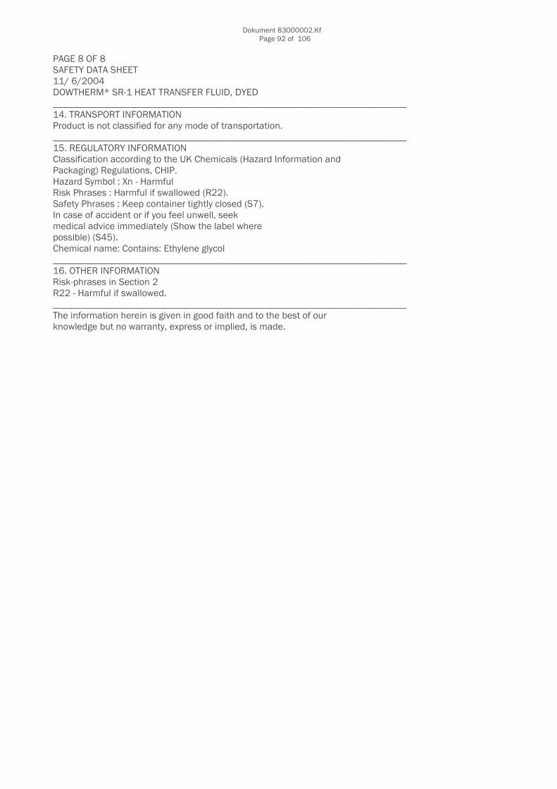
Dokument 83000002.KfPage 92 of 106
PAGE 8 OF 8SAFETY DATA SHEET11/ 6/2004DOWTHERM* SR-1 HEAT TRANSFER FLUID, DYED________________________________________________________________________14. TRANSPORT INFORMATIONProduct is not classified for any mode of transportation.________________________________________________________________________15. REGULATORY INFORMATIONClassification according to the UK Chemicals (Hazard Information andPackaging) Regulations, CHIP.Hazard Symbol : Xn - HarmfulRisk Phrases : Harmful if swallowed (R22).Safety Phrases : Keep container tightly closed (S7).In case of accident or if you feel unwell, seekmedical advice immediately (Show the label wherepossible) (S45).Chemical name: Contains: Ethylene glycol________________________________________________________________________16. OTHER INFORMATIONRisk-phrases in Section 2R22 - Harmful if swallowed.________________________________________________________________________The information herein is given in good faith and to the best of ourknowledge but no warranty, express or implied, is made.

Dokument 83000002.KfPage 93 of 106
21.2 Safety data for refrigerant oil
MINERAL OIL- . .MSDS Number. M7700 * * * * * Effectrve Dute: 05/19/08 * * * * * Supercedes: 08/18/05
Page 1 of 4-MINERAL OIL1. Product IdentificationSynonyms: Paraffin oil; liquid petrolatum, White Mineral Oil; NujolCAS No.: 8012-95-1Molecular Weight: Not applicable.Chemical Formula: Not au.u. l icable.Product Codes:J.T. Baker: 2705Mallinckrodt: 6357, 63582. Composition/Information on IngredientsIngredient CA5 NO Percent Hdzardous
Oil, Mineral 8017-95-1 90 - 100% Yes-3. Hazards IdentificationEmergency OverviewWARNING! HARMFUL IF SWALLOWED OR INHALED. CAUSES IRRITATION T 0 SKIN, EYES AND RESPIRATORY TRACT.COMBUSTIBLE LIQUID AND VAPOR.SAF-T-DATA("") Ratings (Provtded here for your convenience)Health Rating: 2 - ModerateFlammability Rating: 1 - SlightReactivity Rating 0 - NoneContact Rating: 2 - ModerateLab Protective Equip: GOGGLES; LAB COAT; VENT HOOD; PROPER GLOVESStorage Color Code: Green (General Storage)Potential Health EffectsInhalation:Causes irritation to the respiratory tract. Symptoms may include coughing, shortness of breath. Inhalation ofmist or vapor may produce aspiration pneumonia.Ingestion:Material is a cathartic and can cause serious diarrhea. Nausea and vomiting may also occur and possibly abdominal cramping. Aspiration of mineral oil into thelungs can cause chemical pneumonia.Skin Contact:Prolonged contact may cause irritation; occasionally dermatitis due to hypersensitivity occurs.Eye Contact:Mists or fumes can irritate the eyes. Can cause discomfort similar to motor oil.Chronic Exposure:Prolonged or repeated skin exposure may cause dermatitis. Highly refined mineral 011s are not classified as human carcinogens. However, related forms(untreated and mildly-treated oils) are listed as human carcinogens by both NTP and IARC.Aggravation of Pre-existing Conditions:Persons with pre-existing Skin disorders or impaired respiratory function may be more susceptible to the effects of the substance.MINERAL OIL Page 2 of 44. First Aid MeasuresInhalation:

Dokument 83000002.KfPage 94 of 106
Remove to fresh air. If not breathing, give artificial respiration. If breathing is difficult, give oxygen. Get medical attention.Ingestion:If swallowed, D0 NOT INDUCE VOMITING. Give large quantities of water. Never give anything by mouth to an unconscious Person. Get medical attentionimmediately. Aspiration hazard.Skin Contact:Immediately flush skin with plenty of water for at least 15 minutes. Remove contaminated clothing and shoes. Get medical aitention. Wash clothing before reuse.Thoroughly clean shoes before reuse.Eye Contact:Immediately flush eyes with plenty of water for at least 15 minutes, lifting lower and upper eyelids occasionally. Get medical attention immediately.5. Fire Fighting MeasuresFire:Flash point: 135C (275F) CCAutoignition temperature. 260 - 370C (500 - 698F)Combustible Liquid and Vapor!Explosion:Not considered to be an explosion hazard.Fire Extinguishing Media:Water spray, dry chemical, alcohol foam, or carbon dioxide. Water or foam may cause frothing. Do not allow water runoff to enter sewers or watenvays.Special Information:In the event of a fire, wear full protective clothing and NIOSH-approved self-contained breathing apparatus with full facepiece operated in the pressure demandor other positive pressure mode.6. Accidental Release MeasuresVentilate area of leak or spill. Remove all sources of ignition. Wear appropriate personal protective equipment as specified in Section 8. Isolate hazard area. Keepunnecessary and unprotected personnel from entering. Contain and recover liquid when possible. Use non-sparking tools and equipment. Collect liquid in anappropriate container or absorb with an inert material (e. g., vermiculite, dry sand, earth), and place in a chemical waste container. Do not use combustiblematerials, such as saw dust Do not flush to sewer!7. Handling and StorageKeep in a tightly closed container. Store in a cool, dry, ventilated area away from sources of heat or ignition.Protect against physical damage. Store separatelyfrom reactive or combustible materials, and out of direct sunlight. Containers of this material may be hazardous when empty since they retain product residues(vapors, liquid); obsewe all warnings and precautions Iisted for the product.8. Exposure Controls/Personal ProtectionAirborne Exposure Limits:For Mineral Oil; Mistedl:-0SHA Permissible Exposure Limit (PEL): 5 mgim3-ACGIH Threshold Limit Value (TLV).5 mgim3 (TWA) 10 mgIm3 (STEL)(las sampled by method that does not collect vapor)( IRefers to airborne mist of mineral oil)Ventilation System:A system of local andlor general exhaust is recommended to keep employee exposures below the Airborne Exposure Limits. Local exhaust ventilation isgenerally preferred because it can control the emissions of the contaminant at its source, preventing dispersion of it into the general work area. Please refer to theACGIH document, lndustrial Ventilaiion. A Manual of recommendedPractices, most recent edition, for details.Personal Respirators (NIOSH Approved):

Dokument 83000002.KfPage 95 of 106
If the exposure limit is exceeded and engineering conbols are not feasible, a half facepiece particulate respirator (NIOSH type P95 or R95 filters) may be wornfor up to ten times the exposure Iimit or the maximum use concentration specified by the appropriate regulatory agency or respirator supplier, whichever islowest.. A full-face piece particulate respirator (NIOSH type P100 or RlOO filters) may be wom up to 50 times the exposure Iimit, or the maximum useconcentration specified by the appropriate regulatory agency, or respirator supplier, whichever is lowest. Please note that N filters are not recommended for thismaterial. For emergencies or instances where the exposure levels are not known, use a full-facepiece positive-pressure, air-supplied respirator. WARNING. Airpurifyingrespirators do not protect workers in oxygen-deficient atmospheres.Skin Protection:Wear impewious protective clothing, including boots, gloves, lab coat, apron or coveralls, as appropriate, to prevent skin contact.Eye Protection:Use chemical safety goggles andor a full face sbield where splashing is possible. Maintain eye wash fountain and quick-drench facilities in work area.9. Physical and Chemical PropertiesAppearance:Clear oily liquid.Odor:Odorless.Solnbility:MINERAL OIL Page 3 of 4Insoluble in water.Specific Gravity:Heavy: 0.845 to 0.905 Light. 0.818 to 0.880pH:,No inforrnation found% Volatiles by volume @ 21C (70F):0Boiling Point:260 - 330C (500 - 626F)Melting Point:No information foundVapor Density (Air=l):ca. 9Vapor Pressure (mm Hg):< 0 5Evaporation Rate (BuAc=l):No inforrnation found.10. Stability and ReactivityStability:Stable under ordinary conditions of use and storage. May solidify at room temperatureHazardous DmedixXmposition Products:Carbon dioxide and carbon monoxide may form when heated to dmedixXmpositionHazardous Polymerization:Will not occur.Iucompatibilities:Strong oxidizers.Conditions to Avoid:Heat, flames, ignition sources and incompatibles11. Toxicological InformationIrritation Data, rabbit (Std Draize). skin- 100 mg/24H, mild; eye= 500 mg, moderate. Investigated as a tumorigen. Oral rat LD50: 22 gdkg-------\Cancer Llsts\-.--..-- . .- ........................................---NTP Carclnoyen---

Dokument 83000002.KfPage 96 of 106
Ingred~ent Known Rnticipated IARC Category-------------- . - - - - - - - - - - - - - - - - - - - - - - - - - - - - - - - - - . - . - - - -011, Mineral (8012 95 11 NO NO None12. medixXlogical InformationEnvironmeutal Fate:No information found.Environmental Toxicity:No information found.13. Disposal ConsiderationsWhatever cannot be saved for recovery or recycling should be managed in an appropriate and approved waste disposal facility Processing, use or contaminationof this product may change the waste management options. State and local disposal regulations may differ from federal disposal regulations. Dispose of containerand unused contents in accordance with federal, state and local requirements.14. Transport InformationNot regulated.15. Regulator~I nformation--------\Chemical Inventory Status - Part I\---------------------------- ---Inyredlent TSCA EC Japan Australla-------------- -... .----------------------- ------ -------- --- ---011, Mineral (8012-95-11 Yes Yes No Yes. - - . - . - \Chernical lnventory Status - Part 2\--------- --- ------------ Canada--Ingredient Korea DSL NDSL Phil...................... -- - -------------- ----- --- ---- -----011, Mlnerdl (8012-95-11 Yes Yes No YesMINERAL OIL Page 4 of 4- - - - - - - - \Federal, State & International RegulPtions - Part I\--------- S m 302- ------ SARA 313- -----I-ng-r-e-d-i-e-n-t- - R-Q-- -T-P-Q- - -L-is-t- Che-m-i-c-a-l- -C-a-t-g-.-011, Mlneral (8012-95-11 NO No NO NO- - - - - - - - \Federal, State & International Requlations - Part 2\-----------------RCRA- -TSCAIngredientCERCLA 261.33 8 (d)------ - - - - - - - - - - - -Oil, Mineral (8012 -95-11 NO No NoChemical Weapons Convention: No TSCA 1 2 ( b ) : No CDTA: NoSARA 311/312: Acute: Yes Chronic: No Fire: Yes Pressure: NoReactivity: No (Pure / Liquid)Australian Hazchem Code: None allocated.Poison Schedule: S5WHMIS:This MSDS has been prepared according to the hazard criteria of the Controlled Products Regulations (CPR)and the MSDS contains all of the informationrequired by the CPR.16. Other InformationNFPA Ratings: Health: 0 Flammability: 1 Reactivity 0Label Hazard Waruing:WARNING! HARMFUL IF SWALLOWED OR INHALED. CAUSES IRRITATION T0 SKIN, EYES AND RESPIRATORY TRACT. COMBUSTIBLELIQUID AND VAPOR.Label Precautions:Avoid breathing mist.Keep container closed.Use only with adequate ventilation.Avoid contact with eyes, skin and clothing.Wash thoroughly after handling.

Dokument 83000002.KfPage 97 of 106
Keep away from heat, sparks and flame.Label First Aid:If swallowed, D0 NOT INDUCE VOMITING. Give large quantities of water. Never give anything by mouth to an unconscious person. Get medical attentionimmediately. In case of contact, immediately flush eyes or skin with plenty of water for at least 15 minutes. Remove contaminated clothing and shoes. Washclothing before reuse If inhaled, remove to fresh air. If not breathing, give artificial respiration. If breathing isdifficult, give oxygen. In all cases, get medicalattention.Product Use:Laboratory Reagent.Revision Information:No Changes.Disclaimer: ................................................................................................Mallinckrodt Baker, Inc. provides the information contained herein in good faith but makes no representation as to its comprehensiveness or accuracy.This document is intended only as a guide to the appropriate precautionary handling of the material by a properly trained person using this product.Individuals receiving the information must exercise their independeut judgment in determining its appropriateness for a particular purpose.MALLINCKRODT BAKER, INC. MAKES NO REPRESENTATIONS OR WARRANTIES, EITHER EXPRESS OR IMPLIED, INCLUDINGWITHOUT LIMITATION ANY WARRANTIES OF MERCHANTABILITY, FITNESS FOR A PARTICULAR PURPOSE WITH RESPECT T 0THE INFORMATION SET FORTH HEREIN OR THE PRODUCT T 0 WHICH THE INFORMATION REFERS. ACCORDINGLY,MALLINCKRODT BAKER, INC. WILL NOT BE RESPONSIBLE FOR DAMAGES RESULTINC FROM USE OF OR RELIANCE UPON THISINFORMATION. ................................................................................................Prepared by: Environmental Health & SafetyPhone Number. (3 14) 654-1600 (U.S.A.)

Dokument 83000002.KfPage 98 of 106
21.3 Safety data for refrigerant R407c1. CHEMICAL PRODUCT AND COMPANY IDENTIFICATION PRODUCT NAME: R-407C DISTRIBUTOR: For Example:National Refrigerants, Inc. 661 Kenyon Avenue Bridgeton, New Jersey 08302 FOR MORE INFORMATION CALL: IN CASE OF EMERGENCY CALL: (Monday-Friday, 8:00am-5:00pm) CHEMTREC: 1-800-424-9300 1-800-262-0012 2. COMPOSITION / INFORMATION ON INGREDIENTS
INGREDIENT NAME CAS NUMBER WEIGHT % Difluoromethane (HFC-32) 75-10-5 23 Pentafluoroethane (HFC-125) 354-33-6 25 1,1,1,2-Tetrafluoroethane (HFC-134a) 811-97-2 52 Trace impurities and additional material names not listed above may also appear in Section 15 toward the end of the MSDS. These materials may be listed for local “Right-To-Know” compliance and for other reasons. 3. HAZARDS IDENTIFICATION
EMERGENCY OVERVIEW: Colorless, volatile liquid with ethereal and faint sweetish odor. Non-flammable material. Overexposure may cause dizziness and loss of concentration. At higher levels, CNS depression and cardiac arrhythmia may result from exposure. Vapors displace air and can cause asphyxiation in confined spaces. At higher temperatures, (>250°C), dmedixXmposition products may include Hydrofluoric Acid (HF) and carbonyl halides. POTENTIAL HEALTH HAZARDS
SKIN: Irritation would result from a defatting action on tissue. Liquid contact could cause frostbite. EYES: Liquid contact can cause severe irritation and frostbite. Mist may irritate.
INHALATION: R-407C is low in acute toxicity in animals. When oxygen levels in air are reduced to 12-14% by displacement, symptoms of asphyxiation, loss of coordination, increased pulse rate and deeper respiration will occur. At high levels, cardiac arrhythmia may occur. ____________________________________________________________________________________________________________ MSDS: R-407C Page 1 of 7 Current Issue Date: August, 2007

Dokument 83000002.KfPage 99 of 106
INGESTION: Ingestion is unlikely because of the low boiling point of the material. Should it occur, discomfort in the gastrointestinal tract from rapid evaporation of the material and consequent evolution of gas would result. Some effects of inhalation and skin exposure would be expected. DELAYED EFFECTS: None known. Ingredients found on one of the OSHA designated carcinogen lists are listed below. INGREDIENT NAME NTP STATUS IARC STATUS OSHA LISTNo ingredients listed in this section 4. FIRST AID MEASURES
SKIN: Promptly flush skin with water until all chemical is removed. If there is evidence of frostbite, bathe (do not rub) with lukewarm (not hot) water. If water is not available, cover with a clean, soft cloth or similar covering. Get medical attention if symptoms persist. EYES: Immediately flush eyes with large amounts of water for at least 15 minutes (in case of frostbite water should be lukewarm, not hot) lifting eyelids occasionally to facilitate irrigation. Get medical attention if symptoms persist. INHALATION: Immediately remove to fresh air. If breathing has stopped, give artificial respiration. Use oxygen as required, provided a qualified operator is available. Get medical attention. Do not give epinephrine (adrenaline). INGESTION: Ingestion is unlikely because of the physical properties and is not expected to be hazardous. Do not induce vomiting unless instructed to do so by a physician. ADVICE TO PHYSICIAN: Because of the possible disturbances of cardiac rhythm, catecholamine drugs, such as epinephrine, should be used with special caution and only in situations of emergency life support. Treatment of overexposure should be directed at the control of symptoms and the clinical conditions. 5. FIRE FIGHTING MEASURES
FLAMMABLE PROPERTIES FLASH POINT: Gas, not applicable per DOT regulations FLASH POINT METHOD: Not applicable AUTOIGNITION TEMPERATURE: Unknown for mixture UPPER FLAME LIMIT (volume % in air): None* LOWER FLAME LIMIT (volume % in air): None* *Based on ASHRAE Standard 34 with match ignition FLAME PROPAGATION RATE (solids): Not applicable OSHA FLAMMABILITY CLASS: Not applicable EXTINGUISHING MEDIA: Use any standard agent – choose the one most appropriate for type of surrounding fire (material itself is not flammable) ____________________________________________________________________________________________________________ MSDS: R-407C Page 2 of 7 Current Issue Date: August, 2007

Dokument 83000002.KfPage 100 of 106
UNUSUAL FIRE AND EXPLOSION HAZARDS: R-407C is not flammable at ambient temperatures and atmospheric pressure. However, this material will bmedixXme combustible when mixed with air under pressure and exposed to strong ignition sources. Contact with certain reactive metals may result in formation of explosive or exothermic reactions under specific conditions (e.g. very high temperatures and/or appropriate pressures). SPECIAL FIRE FIGHTING PRECAUTIONS/INSTRUCTIONS: Firefighters should wear self-contained, NIOSH-approved breathing apparatus for protection against possible toxic dmedixXmposition products. Proper eye and skin protection should be provided. Use water spray to keep fire-exposed containers cool. 6. ACCIDENTAL RELEASE MEASURES
IN CASE OF SPILL OR OTHER RELEASE: (Always wear recommended personal protective equipment.) Evacuate unprotected personnel. Protected personnel should remove ignition sources and shut off leak, if without risk,and provide ventilation. Unprotected personnel should not return until air has been tested and determined safe, including low- lying areas. Spills and releases may have to be reported to Federal and/or local authorities. See Section 15 regarding reporting requirements. 7. HANDLING AND STORAGE
NORMAL HANDLING: (Always wear recommended personal protective equipment.) Avoid breathing vapors and liquid contact with eyes, skin or clothing. Do not puncture or drop cylinders, expose them to open flame or excessive heat. Use authorized cylinders only. Follow standard safety precautions for handling and use of compressed gas cylinders.
R-407C should not be mixed with air above atmospheric pressure for leak testing or any other purpose. STORAGE recoMMENDATIONS: Store in a cool, well-ventilated area of low fire risk and out of direct sunlight. Protect cylinder and its fittings from physical damage. Storage in subsurface locations should be avoided. Close valve tightly after use and when empty. 8. EXPOSURE CONTROLS / PERSONAL PROTECTION
ENGINEERING CONTROLS: Provide local ventilation at filling zones and areas where leakage is probable. Mechanical (general) ventilation may be adequate for other operating and storage areas. PERSONAL PROTECTIVE EQUIPMENT SKIN PROTECTION: Skin contact with refrigerant may cause frostbite. General work clothing and gloves (leather) should provide adequate protection. If prolonged contact with the liquid or gas is anticipated, insulated gloves constructed of PVA, neoprene or butyl rubber should be used. Any contaminated clothing should be promptly removed and washed before reuse. ____________________________________________________________________________________________________________ MSDS: R-407C Page 3 of 7 Current Issue Date: August, 2007

Dokument 83000002.KfPage 101 of 106
EYE PROTECTION: For normal conditions, wear safety glasses. Where there is reasonable probability of liquid contact, wear chemical safety goggles. RESPIRATORY PROTECTION: None generally required for adequately ventilated work situations. For accidental release or non-ventilated situations, or release into confined space, where the concentration may be above the PEL of 1,000 ppm, use a self-contained, NIOSH- approved breathing apparatus or supplied air respirator. For escape: use the former or a NIOSH-approved gas mask with organic vapor canister. ADDITIONAL recoMMENDATIONS: Where contact with liquid is likely, such as in a spill or leak, impervious boots and clothing should be worn. High dose-level warning signs are recommended for areas of principle exposure. Provide eyewash stations and quick-drench shower facilities at convenient locations. For tank cleaning operations, see OSHA regulations, 29 CFR 1910.132 and 29 CFR 1910.133. EXPOSURE GUIDELINES INGREDIENT NAME ACGIH TLV OSHA PEL OTHER LIMIT Difluoromethane None None **1000 ppm TWA (8hr) Pentafluoroethane None None **1000 ppm TWA (8hr)
1,1,1,2-Tetrafluoroethane None None **1000 ppm TWA (8hr) * = Limit established by National Refrigerants, Inc. ** = Workplace Environmental Exposure Level (AIHA) *** = Biological Exposure Index (ACGIH) OTHER EXPOSURE LIMITS FOR POTENTIAL DmedixXMPOSITION PRODUCTS: Hydrogen Fluoride: ACGIH TLV: 3 ppm ceiling
9. PHYSICAL AND CHEMICAL PROPERTIES
APPEARANCE: Clear, colorless liquid and vapor PHYSICAL STATE: Gas at ambient temperatures MOLECULAR WEIGHT: 86.2 CHEMICAL FORMULA: CH2F2, CF3CHF2, CH2FCF3 ODOR: Faint ethereal odor SPECIFIC GRAVITY (water = 1.0): 1.16 @ 21.1°C (70°F) SOLUBILITY IN WATER (weight %): Unknown pH: Neutral BOILING POINT: -43°C (-45.4°F) FREEZING POINT: Not determined VAPOR PRESSURE: 156.2 psia @ 70°F
356.7 psia @ 130°F VAPOR DENSITY (air = 1.0): 3.0 EVAPORATION RATE: >1 COMPARED TO: CC14 = 1 % VOLATILES: 100 FLASH POINT: Not applicable (Flash point method and additional flammability data are found in Section 5.) ____________________________________________________________________________________________________________ MSDS: R-407C Page 4 of 7

Dokument 83000002.KfPage 102 of 106
10. STABILITY AND REACTIVITY NORMALLY STABLE? (CONDITIONS TO AVOID):
The product is stable. Do not mix with oxygen or air above atmospheric pressure. Any source of high temperature, such as lighted cigarettes, flames, hot spots or welding may yield toxic and/or corrosive dmedixXmposition products. INCOMPATIBILITIES: (Under specific conditions: e.g. very high temperatures and/or appropriate pressures) – Freshly abraded aluminum surfaces (may cause strong exothermic reaction). Chemically active metals: potassium, calcium, powdered aluminum, magnesium and zinc. HAZARDOUS DmedixXMPOSITION PRODUCTS: Halogens, halogen acids and possibly carbonyl halides. HAZARDOUS POLYMERIZATION: Will not occur. 11. TOXICOLOGICAL INFORMATION
IMMEDIATE (ACUTE) EFFECTS: HFC-32: LC50 : 4 hr. (rat) - 520,000 ppm / Cardiac Sensitization threshold (dog) 350,000 ppm
HFC-125: LC50 : 4 hr. (rat) - > 800,000 ppm / Cardiac Sensitization threshold (dog) 75,000 ppm HFC-134a: LC50: 4 hr. (rat) - > 500,000 ppm / Cardiac Sensitization threshold (dog) > 80,000 ppm
DELAYED (SUBCHRONIC AND CHRONIC) EFFECTS: HFC-32: Teratogenic NOEL (rat and rabbit) – 50,000 ppm
Subchronic inhalation (rat) NOEL – 50,000 ppm HFC-125: Teratogenic NOEL (rat and rabbit) – 50,000 ppm
Subchronic inhalation (rat) NOEL - > 50,000 ppm Chronic NOEL – 10,000 ppm
HFC-134a: Teratogenic NOEL (rat and rabbit) – 40,000 ppm Subchronic inhalation (rat) NOEL – 50,000 ppm Chronic NOEL – 10,000 ppm OTHER DATA: HFC-32, HFC-125, HFC-134a: Not active in four genetic studies 12. medixXLOGICAL INFORMATION
Degradability (BOD): R-407C is a gas at room temperature; therefore, it is unlikely to remain in water. Octanol Water Partition Coefficient: Unknown for mixture ____________________________________________________________________________________________________________ MSDS: R-407C Page 5 of 7 Current Issue Date: August, 2007

Dokument 83000002.KfPage 103 of 106
13. DISPOSAL CONSIDERATIONS RCRA Is the unused product a RCRA hazardous waste if discarded? Not a hazardous waste. If yes, the RCRA ID number is: Not applicable. OTHER DISPOSAL CONSIDERATIONS: Disposal must comply with federal, state, and local disposal or discharge laws. R-407C is subject to U.S. Environmental Protection Agency Clean Air Act Regulations Section 608 in 40 CFR Part 82 regarding refrigerant recycling. The information offered here is for the product as shipped. Use and/or alterations to the product such as mixing with other materials may significantly change the characteristics of the material and alter the RCRA classification and the proper disposal method. 14. TRANSPORT INFORMATION
US DOT PROPER SHIPPING NAME: Refrigerant gas R 407C US DOT HAZARD CLASS: 2.2 US DOT PACKING GROUP: Not applicable US DOT ID NUMBER: UN3340 For additional information on shipping regulations affecting this material, contact the information number found in Section 1. 15. REGULATORY INFORMATION
TOXIC SUBSTANCES CONTROL ACT (TSCA) TSCA INVENTORY STATUS: Components listed on the TSCA inventory OTHER TSCA ISSUES: None SARA TITLE III / CERCLA “Reportable Quantities” (RQs) and/or “Threshold Planning Quantities” (TPQs) exist for the following ingredients. INGREDIENT NAME SARA / CERCLA RQ (lb.) SARA EHS TPQ (lb.) No ingredients listed in this section Spills or releases resulting in the loss of any ingredient at or above its RQ requires immediate notification to the National Response Center [(800) 424-8802] and to your Local Emergency Planning Committee. SECTION 311 HAZARD CLASS: IMMEDIATE PRESSURE SARA 313 TOXIC CHEMICALS: The following ingredients are SARA 313 “Toxic Chemicals”. CAS numbers and weight percents are found in Section 2. INGREDIENT NAME COMMENT No ingredients listed in this section ____________________________________________________________________________________________________________ MSDS: R-407C Page 6 of 7 Current Issue Date: August, 2007

Dokument 83000002.KfPage 104 of 106
STATE RIGHT-TO-KNOW In addition to the ingredients found in Section 2, the following are listed for state right-to-know purposes. INGREDIENT NAME WEIGHT % COMMENT No ingredients listed in this section ADDITIONAL REGULATORY INFORMATION: R-407C is subject to U.S. Environmental Protection Agency Clean Air Act Regulations at 40 CFR Part 82.
WARNING: Do not vent to the atmosphere. To comply with provisions of the U.S. Clean Air Act, any residual must be recovered. Contains Pentafluoroethane (HFC-125), Difluoromethane (HFC-32), and Tetrafluoroethane (HFC-134a), greenhouse gases which may contribute to global warming.
WHMIS CLASSIFICATION (CANADA): This product has been evaluated in accordance with the hazard criteria of the CPR and the MSDS contains all the information required by the CPR. FOREIGN INVENTORY STATUS:
EU – EINECS # 2065578 – HFC-125 # 2008394 – HFC-32
# 223770 – HFC-134a 16. OTHER INFORMATION
CURRENT ISSUE DATE: August, 2007 PREVIOUS ISSUE DATE: October, 2006 OTHER INFORMATION: HMIS Classification: Health – 1, Flammability – 1, Reactivity – 0 NFPA Classification: Health – 2, Flammability – 1, Reactivity – 0 ANSI / ASHRAE 34 Safety Group – A1 Regulatory Standards:
1. OSHA regulations for compressed gases: 29 CFR 1910.101 2. DOT classification per 49 CFR 172.101
Toxicity information per PAFT Testing 17. DISCLAIMER
National refrigerants, Inc. believes that the information and recommendations contained herein (including data and statements) are accurate as of the date hereof. NO WARRANTY OF FITNESS FOR ANY PARTICULAR PURPOSE, WARRANTY OF MERCHANTABILITY, OR ANY OTHER WARRANTY, EXPRESSED OR IMPLIED, IS MADE CONCERNING THE INFORMATION PROVIDED HEREIN. The information provided herein relates only to the specific product designated andmay not be valid where such product is used in combination with any other methods or use of the product and of the information referred to herein are beyond the control of National Refrigerants. National Refrigerants expressly disclaims any and all liability as to any results obtained or arising from any use of the product or reliance on such information. ____________________________________________________________________________________________________________ MSDS: R-407C Page 7 of 7 Current Issue Date: August, 2007
Dokument 83000002.KfPage 105 of 106
22 Wiring diagramPlease see seperate files on this CDWiring diagram for medixX50 – medixX70 and FCU
23 KKT Service
Manufacturerait-deutschland GmbH
Industriestraße 3
95359 Kasendorf
Germany
T +49 9228 9977 7190
F +49 9228 9977 7474
W www.kkt-chillers.com
Service Center USAKKT chillers, Inc.
765 Dillon Drive
Wood Dale, IL 60191
T +1 847 734 1600
F +1 847 734 1601
TF +1 866 517 6867 ← 24/7 Hotline

Dokument 83000002.KfPage 106 of 106
24 Declaration of Conformity (affect inside Europe)