User Manual Installation and Operation Wideband … · User Manual Installation and Operation...
52
User Manual Installation and Operation Wideband Airborne Radio Direction Finder R R T T - - 6 6 0 0 0 0 (SAR-DF 517) Standard Version Law Enforcement Version
Transcript of User Manual Installation and Operation Wideband … · User Manual Installation and Operation...
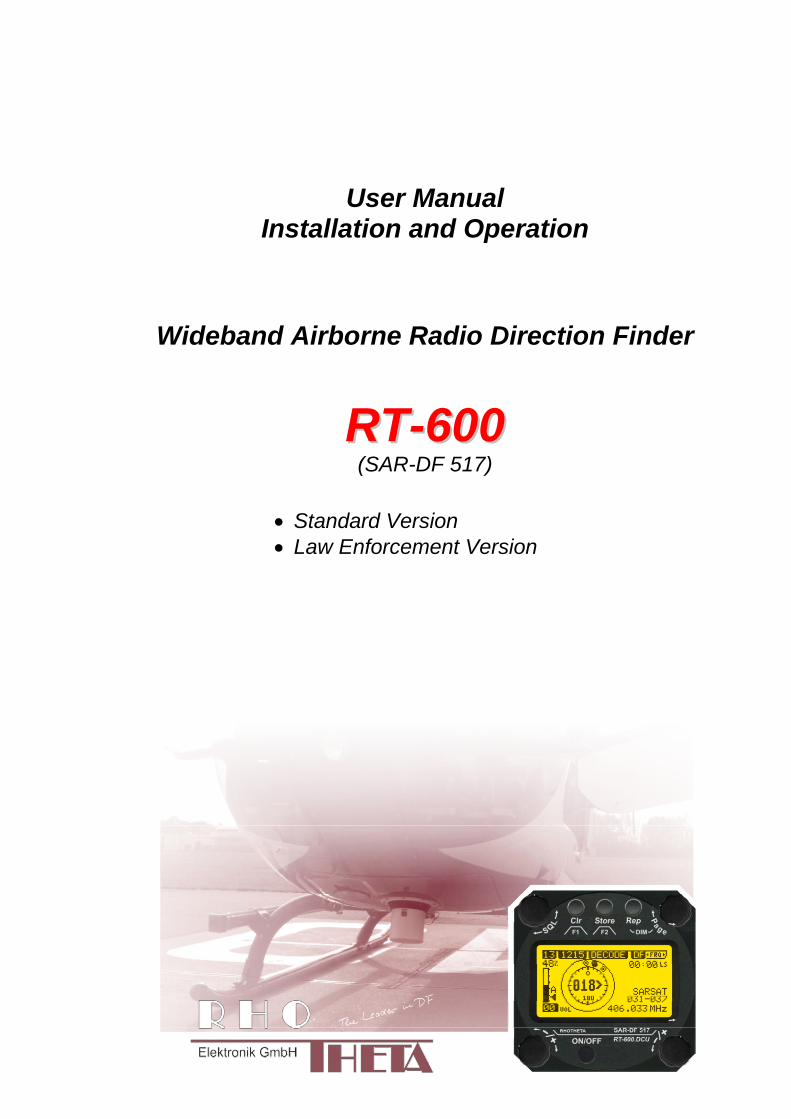
User Manual Installation and Operation
Wideband Airborne Radio Direction Finder
RRTT--660000 (SAR-DF 517)
Standard Version Law Enforcement Version
User manual Direction Finder RHOTHETA RT-600
- 2 -
Edited by
RHOTHETA Elektronik GmbH Dr-Ingeborg-Haeckel-Str 2 82418 Murnau Germany Tel +49 8841 4879 - 0 Fax +49 8841 4879 - 15 Internet wwwrhothetade E-Mail emailrhothetade Copyright RHOTHETA Elektronik GmbH All rights reserved RT-600 User Manual - Installation and Operating PN RT-8699 Issue [20130925] [Rev 302]
Edition valid for DCU with Software [Rev ge 330 hellip] Edition valid for AU with Software [Rev ge 330 hellip]
LoJack is a registered trademark of LoJack Corporation Note
The manufacturer reserves the right on making modifications of the product described herein at any time and without previous information
User manual Direction Finder RHOTHETA RT-600
- 3 -
Index
1 GENERAL INFORMATION 6
11 Purpose of use of the direction finder 6
12 Scope of delivery 7 121 RT-600 A (PN RT-8610) 7 122 RT-600 A NVG (PN RT-8611) 7 123 RT-600 LE (PN RT-8620) 7 124 RT-600 LE NVG (PN RT-8623) 7
13 Main system configuration settings 7
2 OPERATING 8
21 General Operating Principles 8 211 Push-buttons with double function 9 212 Power-On procedure 10 213 Main Pages Selection 11 214 Dimming function 11 215 Squelch Operation 12
22 Frequency (FRQ) Selection Page 14 221 Selecting a Frequency 14 222 Recalling and editing frequencies from a memory channel 14 223 Recalling frequencies from fixed frequencies or CospasSarsat Channels 15 224 Editing a Frequency 16 225 Selecting a Frequency Band 17
23 Direction Finder (DF) Mode 18 231 Operating Elements in DF Mode 18 232 Standard Display in DF Mode 19 233 Special Options in COSPAS-SARSAT DF Mode 20 234 COSPAS-SARSAT Decode Window 21 235 Tracking 121500 MHz while in COSPAS-SARSAT Mode 22 236 COSPAS-SARSAT Scan Mode 23 237 Marine Ship Scan Mode 24
24 Law Enforcement Operation 25 241 Power-On procedure 25 242 LoJack Scan Mode Start scanning for a VLU Code 25 243 LoJack Scan Mode from any other page 26 244 Manual activation of LoJack Scan Mode 27 245 Receiving and accepting a new VLU Code 28 246 Entering a new VLU Code manually 28 247 Tracking one VLU Code while monitoring new VLU Codes 29 248 Tracking one VLU Code and receiving a new VLU Code 29 249 Switching to a new VLU Code 30 2410 ldquoBlockingrdquo function of one LoJack VLU Code 30 2411 Tracking in the 216 to 220 MHz band 31
25 Setup Edit Page 31
3 ERROR MESSAGES 33
4 INSTALLATION 34
41 Antenna unit 34 411 Influence of antenna location and environment on the bearing accuracy 35
42 Display and Control Unit 37
43 System Interconnect Wiring Diagram 38
5 TECHNICAL DATA 39
51 Electric features 39
52 Interface 41
53 Mechanical features 42
User manual Direction Finder RHOTHETA RT-600
- 4 -
6 APPENDIX 44
61 Frequency Ranges 44
62 Frequencies of channels on maritime band 45
63 Serial interface data protocol (short description) 46 631 General 46 632 Serial standard output (protocol description) 47 633 DCU Info output (protocol description) 49 634 Optional extended serial output (protocol description) 50 635 Optional serial input (protocol description) 52
User manual Direction Finder RHOTHETA RT-600
- 5 -
List of figures Fig 1) RT-600 Airborne Direction Finder System 7 Fig 2) RT-600DCU Front Panel Layout 8 Fig 3) Push buttons short-time keypress 9 Fig 4) Push buttons longer-time keypress 9 Fig 5) Power-On Screen 10 Fig 6) Page Selection 11 Fig 7) Dimming Adjustment 11 Fig 8) Manual squelch mode correct squelch adjustment 13 Fig 9) Manual squelch mode Incorrect squelch adjustment 13 Fig 10) Automatic squelch mode 13 Fig 11) Automatic squelch mode with strong signal 13 Fig 12) Automatic squelch mode and not adjustable by the user 13 Fig 13) Open FRQ Page 14 Fig 14) FRQ ndash Frequency Selection Page 14 Fig 15) Recall frequency of Memory channel 3 14 Fig 16) FRQ Selection Page with FIX1 selected 15 Fig 17) FRQ Selection Page before frequency editing 16 Fig 18) FRQ Selection Page after frequency editing 16 Fig 19) FRQ Selection Page (bands) 17 Fig 20) Operational Elements in DF Mode 18 Fig 21) DF Mode 19 Fig 22) Operational Elements and Display in COSPAS-SARSAT DF Mode 20 Fig 23) COSPAS-SARSAT Beacon Information Page 21 Fig 24) Tracking 121500 MHz while in COSPAS-SARSAT Mode 22 Fig 25) FRQ Selection Page with SCN COSPAS-SARSAT Scan Page selected 23 Fig 26) DF page with active COSPAS-SARSAT Scan Mode at the DF page 23 Fig 27) DF Mode FRQ = 156800 MHz F1 for scan function 24 Fig 28) DF Mode active scanning in process 24 Fig 29) STARTUP Screen (see 211 for details) 25 Fig 30) LoJack Scan Mode unit is scanning for a LoJack VLU Code 25 Fig 31) Hotkey F2 26 Fig 32) FRQ Selection Page FRQ = LoJack BAND = LoJack (164-174 MHz) 27 Fig 33) DF Mode with LoJack filter OFF 27 Fig 34) LoJack Scan Mode with new VLU Code received 28 Fig 35) LoJack Scan Mode with new VLU Code entered manually 28 Fig 36) DF Mode with active VLU Code and LoJack filter ON 29 Fig 37) DF Mode with active VLU Code and announcement of new VLU Code 29 Fig 38) LoJack Scan Page with one active VLU Code and one new VLU Code 30 Fig 39) LoJack Scan Page with one active VLU Code and audio OFF 30 Fig 40) Accessing the Setup Page 31 Fig 41) Setup Page 32 Fig 42) Error Messages 33 Fig 43) Antenna Mounting Drawing 34 Fig 44) Antenna Installed in a Bad Location 35 Fig 45) Antenna Installed in Good Locations 36 Fig 46) DCU Mounting Drawing 37 Fig 47) System Interconnect Wiring Diagram 38 Fig 48) DCU Mechanical Drawing (all dimensions in [mm]) 42 Fig 49) AU Mechanical Drawing (all dimensions in [mm]) 43 Fig 50) Timing of serial data 46
User manual Direction Finder RHOTHETA RT-600
- 6 -
1 General information RHOTHETA Elektronik GmbH is the developer and manufacturer of the Direction Finder System RT-600 In the United States of America the system has also been marketed under the system designation SAR-DF 517
11 Purpose of use of the direction finder The RHOTHETA direction finder system RT-600 or SAR-DF 517 is designed to receive and locate emergency signals and special application signals on the international distress and application specific frequencies in the VHF UHF frequency range The system consists of the Display Control Unit (DCU) RT-600DCU-(X)-(X) and the Antenna Unit (AU) RT-600AU-(X) and it is typically mounted on aircraft both manned and unmanned The RT-600 is a modern precision direction finder intended for professional SAR (search and rescue) and LE (Law Enforcement) purposes and there are two versions of the RT-600
The STANDARD or ldquoArdquo version receives and locates signals on all international VHF-UHF emergency frequencies including marine channel 16 and all COSPASSARSAT channels
The LAW ENFORCEMENT or ldquoLErdquo version receives and locates special signals tracked by law enforcement and special ops organizations but it also receives and locates signals on international VHF emergency frequencies including marine channel 16 and all COSPASSARSAT channels
The excellent performance of the RT-600 is possible due to our revolutionary patented antenna (small robust and wideband) and itrsquos sophisticated bearing analyzing algorithms which deliver quick and steady information The RT-600 was designed for usage in harsh conditions mounted on aircraft or vehicles
User manual Direction Finder RHOTHETA RT-600
- 7 -
12 Scope of delivery
121 RT-600 A (PN RT-8610)
Display Control Unit RT-600DCU-(A)-() (PN RT-8605) Antenna Unit RT-600AU-(A) (PN RT-8602) Connector Kit (PN RT-8503) User Manual (PN RT-8699) Cable AU-DCU (PN RT-28146) OPTIONAL
122 RT-600 A NVG (PN RT-8611)
Display Control Unit RT-600DCU-(A)-(N) (PN RT-8606) Antenna Unit RT-600AU-(A) (PN RT-8602) Connector Kit (PN RT-8503) User Manual (PN RT-8699) Cable AU-DCU (PN RT-28146) OPTIONAL
123 RT-600 LE (PN RT-8620)
Display Control Unit RT-600DCU-(L)-() (PN RT-8622) Antenna Unit RT-600AU-(L) (PN RT-8621) Connector Kit (PN RT-8503) User Manual (PN RT-8699) Cable AU-DCU (PN RT-28146) OPTIONAL
124 RT-600 LE NVG (PN RT-8623)
Display Control Unit RT-600DCU-(L)-(N) (PN RT-8624) Antenna Unit RT-600AU-(L) (PN RT-8621) Connector Kit (PN RT-8503) User Manual (PN RT-8699) Cable AU-DCU (PN RT-28146) OPTIONAL
Fig 1) RT-600 Airborne Direction Finder System
13 Main system configuration settings To guarantee a correct configuration and performance the user should verify ndash and change if necessary - the following configuration settings
MOUNTING TOP BOTTOM this parameter indicates if the Antenna Unit is mounted on a TOP or BOTTOM position
EXTERNAL DIMMING MIN MAX if an external voltage is used for dimming the legends the MAX and MIN parameters set respectively the low and high limits of the external analog voltage connected to Pin 8 of the RT-600DCU ldquoPower Supplyrdquo connector
The above settings are available in the SETUP menu For a detailed description see 25 Setup Edit Page on Pg 31
User manual Direction Finder RHOTHETA RT-600
- 8 -
2 Operating Operating the RT-600 direction finder is intentionally simple due to its intuitive human machine interface All operational settings are controlled from the RT-600-DCU Display and Control Unit Of all the controls on the RT-600DCU only the PAGE knob and the ONOFF button have functions which are not dependent on the active page selected by the user
21 General Operating Principles
Fig 2) RT-600DCU Front Panel Layout
(1) gtLC Graphic Displaylt (128 x 64 dots dot-matrix display dark blue on yellow-green background)
showing all relevant operational information depending upon the selected page
(2) gtONOFFlt Push-button to switch on off the system
(3) gtMenult options for rotary and push buttons If a field with dark background and bright text is shown below a button or switch the function described in this field may be selected through the operational element above or below this menu field In case of the Page Menu the active page is high-lighted with dark background while the inactive page is in black letters
(4) gtVolumelt Rotary Switch used depending on the active page to adjust the volume of the audio output or to select frequency values (MHz steps)
(5) gtSQLlt Rotary Switch used depending on the active page to adjust the squelch function or to select specific functions on a page depending upon the interactive menu on the display
(6) Push-buttons (see next page)
(7) gtPagelt Rotary Switch Selects pages ldquoDFrdquo and ldquoFRQrdquo - Page ldquoDFrdquo for direction finder standard bearing operation - Page ldquoFRQrdquo for changing active frequency Also adjusts display brightness if used during DIMMING mode
User manual Direction Finder RHOTHETA RT-600
- 9 -
211 Push-buttons with double function
The three push-buttons (1) (2) and (3) can be used with two different effectshellip
Keypress for short-time (lt 1 sec)
(1) gtF1lt Push-button If pushed for a short time
this button activates the function F1 described in the interactive menu on the display below which depends on the active mode and settings
(2) gtF2lt Push-Button If pushed for a short time this button activates the function F2 described in the interactive menu on the display below which also depends on mode and settings
(3) gtDIMlt Push-Button If pushed for a short time it activates the display DIMMING mode(see 214 Dimming function)
Fig 3) Push buttons short-time keypress
Keypress for longer time (gt 2 sec)
(1) gtCLR lt Push-button If pushed for a longer
time this button activates the CLEAR function
(2) gtSTORElt and special key button If pushed for a longer time and when using the RT-600 LE (LAW ENFORCEMENT) version then the LoJack standard Scan page with all necessary settings is activated (fast-switchover) otherwise the Store functionality is only available at the Setup Page (see 25 Setup Edit Page)
(3) gtReplt Push-Button If pushed for a longer time (ca 3 seconds) it activates the repetition of the last valid relative bearing and signal level information
Fig 4) Push buttons longer-time keypress
User manual Direction Finder RHOTHETA RT-600
- 10 -
212 Power-On procedure
After switching on the DCU pressing the ONOFF pushbutton a startup screen is displayed for five seconds
Fig 5) Power-On Screen
(1) System Type RT-600
(2) System Version ldquo(L)rdquo for LAW ENFORCEMENT version or ldquo(A)rdquo for STANDARD version
(3) Web Address (URL)
(4) Software Revision of AU (antenna unit)
(5) Serial Number of AU
(6) Additional service and maintenance information (the two characters indicate installed options)
(7) Software Revision of DCU (display control unit)
(8) Serial Number of DCU
After five seconds the equipment switches to the operational mode (for LAW ENFORCEMENT version the LoJack Scan page is displayed as home page by default)
User manual Direction Finder RHOTHETA RT-600
- 11 -
213 Main Pages Selection
Two main modes can be selected from the DCU front panel
DF Mode Page displays all relevant operational bearing information depending on the type of signal being received
FREQ SELECTION Page allows to access and edit all pre-programmed frequency memory channels
Fig 6) Page Selection
(1) The gtPagelt rotary switch is used to select the active page
(2) The active page is highlighted with dark background
(3) The inactive page which may be selected is displayed in dark letters on bright background
214 Dimming function
The background of the LC-graphic display is equipped with an LED array and its brightness may be adjusted continuously from 5 to 100 Dimming follows an exponential curve resulting in very accurate adjustment under night conditions
Fig 7) Dimming Adjustment
(1) Pressing the gtRepDIMlt button for a short time activates the
DIMMING mode
(2) Brightness actual information in percentage from 5 to 100 in 5 steps is displayed instead of the ldquoPagerdquo field in the upper right corner of the display
(3) The gtPagelt knob is used to adjust the brightness in 5 steps left and right
The active brightness level of the display will remain stored after switching off the unit separately for day and nightNVG mode
After ca 3 sec of inactivity the display will fall back to the prior main page Dimming of legends can be adjusted in two ways
Internal dimming of legends
Internal dimming is always active If an external dimming voltage is not used or is lt 1V DC legends are dimmed in the same manner as the LC display
External (remote) dimming of legends
If the external dimming voltage is gt 1V DC the brightness of the legends is controlled by the external dimming voltage (Refer to the wiring plan and to the operatingsetup-menu description)
User manual Direction Finder RHOTHETA RT-600
- 12 -
215 Squelch Operation
The main challenge of operating a direction finder is trying to use only the signal transmitted by the target in order to calculate its bearing accurately because noise and RF disturbances will cause misleading bearing indications In order to prevent the direction finder to calculate bearing results which are due to noise and disturbances several techniques are available If a signal can be distinguished from noise or other signals by its message content (eg LoJack ID) only transmissions containing the required message content are used for bearing In other cases the squelch can be used to suppress unwanted weak signals and noise A squelch level called threshold has to be set by the user or automatically by the system All signals with strength below this threshold value will be ignored while signals with strength above this level will cause a bearing indication So for a signal to be usable for bearing calculation it has to be sufficiently stronger than noise or disturbing signals that the receiver can clearly distinguish between wanted and unwanted signals As a result of the squelch technique the receiver sensitivity is reduced to the level set by the squelch threshold decreasing the maximum distance or range to the transmitter However it might be desirable to obtain bearing information even for weak signals which are very close to the noise level In this case it will be necessary to reduce the squelch level below the noise level As soon as the modulation of a signal can be heard on the speaker it can be expected that bearing calculation is possible If the noise is randomly distributed ndash as with ldquowhite noiserdquo ndash and no other signal is received the bearing indication will also be random If the noise is not random but rather a specific disturbance the bearing indication will point to the source of the noise If there is a very weak signal ldquoburiedrdquo in the noise this signal will produce a correct bearing indication thanks to sophisticated bearing technologies used in the RT-600 system Fluctuations due to noise will be small even at low signal levels however the reaction time of the bearing indication can increase To verify if a bearing indication is due to white noise or to an internal disturbance source or if it is due to a valid signal the aircraft should make a slow turn If the bearing indication is due to an external signal eg a SAR beacon the bearing indication should compensate the changed relative flight angle Example with a bearing indication of 30deg The signal is hardly audible as it is buried in the noise The airplane makes a turn left by 60deg If the bearing indication is not changing to approximately 30deg+60deg = 90deg after a few seconds the bearing is likely to be due to noise or internal disturbances from the aircraft Note The weaker a signal is the longer it will take to change the bearing Durations around 5 seconds are not unfamiliar in such cases Therefore it is not useful to use this procedure for signals with short transmission times and low transmit duty cycles such as COSPAS-SARSAT transmission The procedure is best suited for ELT transmission with a continuous signal and still well-suited for ELTs with intermittent transmission (down to 33) In cases where pulsed signals are to be received the receiver is able to decide automatically which squelch level is best-suited for normal operation In such cases an automatic (ldquoArdquo) squelch is provided The threshold is automatically set to a value higher than the calculated noise level The difference in dB between noise and threshold level can be defined in the Setup Menu Refer to the chapter ldquoSetup Pagerdquo for details During AUTO squelch operation the user has the possibility to force the squelch into MANUAL mode but needs to be aware of the operational limitations described in this chapter In cases where the Antenna Unit checks signal validity autonomously and without useful possibilities of user interaction user interaction is not possible and the squelch purely follows internal rules appropriate to the type of signal received
User manual Direction Finder RHOTHETA RT-600
- 13 -
Examples of different squelch settings
Fig 8) Manual squelch mode correct squelch
adjustment
Correct squelch adjustment If the squelch is set to level (b) slightly over the noise level (a) the receiver audio output remains quiet and no wrong noisy bearing is indicated
Fig 9) Manual squelch mode Incorrect squelch
adjustment
Incorrect squelch adjustment If the squelch level is set (b) below the noise level (a) a wrong noisy bearing is indicated
Fig 10) Automatic squelch mode
Automatic squelch mode Automatic squelch mode is indicated by an ldquoArdquo (c) above the squelch level marker Depending on the SN-Ratio setting the squelch level is automatically set slightly higher than the noise level Using the SQL rotary switch (1) the user can change to manual squelch mode Automatic squelch mode can be activated again by setting the squelch level manually to lt 0 or gt 60
Fig 11) Automatic squelch mode with strong signal
Automatic squelch mode with strong signals Strong short receive signals will not modify the squelch level setting
Fig 12) Automatic squelch mode and not adjustable by
the user
Automatic squelch mode level not re-adjustable by user When the squelch is adjusted automatically by the system and the user is not allowed to change it an ldquoXrdquo (c) is displayed above the squelch level marker
User manual Direction Finder RHOTHETA RT-600
- 14 -
22 Frequency (FRQ) Selection Page The Frequency Selection (FRQ Selection) Page allows the user to select a frequency select a band and edit a frequency
Open FRQ Page
From the ldquoDFrdquo standard page activate the Page Rotary Switch in any direction to open the ldquoFRQrdquo Page for Frequency Selection
Fig 13) Open FRQ Page
Fig 14) FRQ ndash Frequency Selection Page
221 Selecting a Frequency
(1) Use the Page knob ldquoFRQrdquo again to select (recall) a frequency from
gtMEMlt four (4) memory channels gtWlt one (1) working (operating) frequency gtFIXlt fixed frequencies gtCPSARlt seven (7) COSPAS-SARSAT channel groups
(2) The actual adjusted frequency
(3) Frequency band-information
Exit Frequency dialogue
(4) Press push-button gtF1lt ldquoEXITrdquo to exit to DF mode (using the actual frequency
222 Recalling and editing frequencies from a memory channel
Recall
(1) With changing the Page rotary knob memory channels 1 4 can be selected The gtmarkerlt symbol indicates the actual memory channel
Edit
(2) MHz plusmn edits the MHz Value of the actual frequency
(3) kHz plusmn edits the kHz Value of the actual frequency
(4) F2 switches to next band
gtMHzlt and gtkHzlt directly changes and overwrites the actual selected memory frequency inside the actual band (see also 224 Editing a Frequency)
Fig 15) Recall frequency of Memory channel 3
User manual Direction Finder RHOTHETA RT-600
- 15 -
223 Recalling frequencies from fixed frequencies or CospasSarsat Channels
Fig 16) FRQ Selection Page with FIX1 selected
(1) ldquoFIXrdquo Selection range for fixed frequencies
for RT-600 Standard version for RT-600 Law Enforcement version
FIX1 ldquoEltPlbrdquo 121500 MHz international VHF air distress emergency frequency
FIX2 ldquoChnl16rdquo 156800 MHz marine VHF emergency radio channel 16
FIX3 ldquoEltMILrdquo 243000 MHz military UHF air distress emergency frequency
FIX1 ldquoEltPlbrdquo 121500 MHz international VHF air distress emergency frequency
FIX2 ldquoChnl16rdquo 156800 MHz marine VHF emergency radio channel 16
FIX3 ldquoLE(USA)rdquo 173xxx MHz LoJack Recovery System
FIX4 ldquoETSSTDrdquo 216487 MHz ETS standard frequency
FIX5 ldquoETSUCVrdquo 216512 MHz ETS ucover frequency
(2) ldquoCPSARrdquo Selection range for Cospas Sarsat channel groups
CPSAR1 ldquo022-028rdquo 406022 hellip 028 MHz Channel A B C
CPSAR2 ldquo031-037rdquo 406031 hellip 037 MHz Channel D E F
CPSAR3 ldquo040-043rdquo 406040 hellip 043 MHz Channel G H
CPSAR4 ldquo046-052rdquo 406046 hellip 052 MHz Channel I J K
CPSAR5 ldquo055-061rdquo 406055 hellip 061 MHz Channel L M N
CPSAR6 ldquo064-070rdquo 406064 hellip 070 MHz Channel O P Q
CPSAR7 ldquo073-076rdquo 406073 hellip 076 MHz Channel R S
User manual Direction Finder RHOTHETA RT-600
- 16 -
224 Editing a Frequency
While on the FRQ SELECTION Page the user can directly edit the frequency displayed
Fig 17) FRQ Selection Page before frequency editing
(1) gtMHzlt Rotary switch for direct adjustment of the displayed MHz range inside the actual band
(1 x step = 1 MHz adjustment)
(2) gtkHzlt Rotary switch for changing the displayed kHz frequency according to the actual band frequency grid (as example 8333 kHz at the VHF airband)
(3) gtF2lt Adjustment of the next available band (see next page gtgt Selecting a Frequency Band)
Fig 18) FRQ Selection Page after frequency editing
If the selected and marked frequency is not one of the MEM [14] channels then the changed frequency is automatically stored in the work frequency WorkFRQ channel
User manual Direction Finder RHOTHETA RT-600
- 17 -
225 Selecting a Frequency Band
While on the FRQ Selection Page each available band can be selected by pressing F2 BAND
(1) Press push button F2 BAND for
switch over to the next band
(2) Designation of actual selected band
(3) Max frequency limits of the actual selected band (depends on wide band options)
Fig 19) FRQ Selection Page (bands)
Frequency bands availability depends on the system version (A LE) and its wide band options (F1 to F4) These optional wide bands are available if ordered in addition to the default bands Here is a listing of DEFAULT and OPTIONAL bands available with each version of the system RT-600 (STANDARD) Listing of bands
Default bands available OPTIONAL extended bands available
Band designation Frequency limits Option Designation Frequency limits
VHF Emergency Band 118000 hellip 124000 MHz gt F1 VHF Air Band 118000 hellip 136992 MHz
VHF Marine Band 154000 hellip 163000 MHz gt F2 Extended VHF Marine 137000 hellip 224995 MHz
UHF Emergency Band 240000 hellip 246000 MHz gt F3 UHF Air Band 225000 hellip 399975 MHz
COSPAS SARSAT 400000 hellip 406092 MHz
UHF FM Band 406100 hellip 410000 MHz gt F4 Additional UHF FM 406100 hellip 470000 MHz
RT-600 (Law Enforcement) Listing of bands
Default bands available OPTIONAL extended bands available
Band designation Frequency limits Option Designation Frequency limits
VHF Emergency Band 118000 hellip 124000 MHz gt F1 VHF Air Band 118000 hellip 136992 MHz
VHF Marine Band 154000 hellip 163000 MHz gt F2 Extended VHF Marine 137000 hellip 163000 MHz
LoJack 164000 hellip 174000 MHz
ETS 216000 hellip 220000 MHz
COSPAS SARSAT 400000 hellip 406092 MHz
User manual Direction Finder RHOTHETA RT-600
- 18 -
23 Direction Finder (DF) Mode Direction Finder (DF) mode is generally used to display all valid information processed by the DF from the signal received from a target transmitter The amount and kind of information displayed by the DCU depends on the type and content of the signal received and processed by the DF Simple signals such as the analog sweep-tone modulation received from a SAR beacon (ELT PLB EPIRB PDD) on 121500 MHz allow displaying only basic bearing information while digital signals such as COSPAS-SARSAT and LOJACK allow displaying more information for ex beacon IDs GPS coordinates codes VLUs etc
231 Operating Elements in DF Mode
Fig 20) Operational Elements in DF Mode
This picture shows the DCU operating in DF Mode on the international emergency frequency 121500 MHz
with an active signal being received (1) gtFREQUENCYlt Rotary switch activates the ldquoFRQrdquo frequency page for changing and selecting the
active frequency The last selected frequency remains stored after switching offon the device The selected frequency is shown on the graphic display bottom right Above additional information for the selected frequency is displayed The use of the rotary switch activates a sub-page Please refer to the Frequency Selection section for details
(2) gtVOLUMElt Rotary switch to adjust the audio output level The volume of a linked external speaker or amplifier can be adjusted in a range from 0 (off) to 99 (maximum loudness) The selected volume is shown in the bottom left corner of the graphic display The volume remains stored after switching offon the device
(3) gtSquelch Levellt adjusts the squelch level The squelch level has to be above the receiving level without signal (noise) Only signals above the squelch level are audible in the loudspeaker and used by the direction finder for bearing indication The gtSQLlt rotary switch allows to select the squelch threshold ie a minimum signal strength of an incoming signal to be processed The current settings on a signal level scale from 0 to 60 is shown in bright letters on dark background below the SQL rotary switch and as an arrow beside the signal Strength Bar-Graph
(4) The gtCLRlt Push-button is used for erasing the internal bearing value averaging store and the Last Signal Timer To activate this function the push-button has to be hold down for a minimum of circa two seconds The sophisticated averaging store increases bearing precision and enables at all an usable
User manual Direction Finder RHOTHETA RT-600
- 19 -
bearing display in case of bad receiving signals (if there is a far away transmitter andor temporary complete loss of a receiving signal) Caused by the averaging procedure a drag error may occur which might be disturbing the bearing indication after a quick change of course of the aircraft or vehicle In this case the indicated bearing value lags by the real bearing value for about two seconds (for very weak signals even longer) By pressing this push-button after a quick change of course the display will show the new bearing value without drag error Additionally the F1CLR Push-Button is used to activate specific functions high-lighted in the menu below the button by pushing it for a short time (here as example ldquoSCANrdquo starts scanning the actual air band)
(5) gtSTORElt push-button Without function except if a special function is high-lighted in the menu line of the display
(6) gtREPEATlt Push-button when pressed and hold for min 3 sec the last valid bearing value with corresponding receiving level is displayed
232 Standard Display in DF Mode
Fig 21) DF Mode
(1) gtRelative Bearing valuelt by means of a sophisticated averaging procedure a steady display is
accomplished as graphic display and as text in the range of 0deghellip 359deg (0deg corresponds to bearing direct ahead)
(2) gtSpreadlt maximum deviation of un-averaged bearing values This is an indicator of bearing quality The wider the range between the directions of maximum deviation the worse the received signal is As a result of the excellent averaging procedure even with a spread of 45deg good bearing results are achieved
(3) gtReceiving levellt (field strength) of the signal as a relative percentage value visualized as bar-graph indication and as decimal value Even without a received signal a certain noise level may be displayed
(4) gtSquelch levellt (independently adjustable and stored for each frequency band) Squelch level is indicated as marker at the Signal Strength Bar-Graph or as direct relative level value A usable bearing analysis can only be achieved if the squelch level is above the noise level (without received signal) If the antenna unit is placed close a heavily disturbing electronic devices the squelch level has to be raised thus making the direction finder being less sensitive In receive modes where the squelch level is set automatically an ldquoArdquo above the marker indicates the ldquoAutosquelchrdquo functionality
(5) gtLast Signallt timer showing the time since a signal has been received for the last time (ie since a signal has been stronger than the squelch level) Values are ldquominutes secondsrdquo
User manual Direction Finder RHOTHETA RT-600
- 20 -
233 Special Options in COSPAS-SARSAT DF Mode
Especially for the use together with beacons transmitting a data signal according to COSPAS-SARSAT specifications in the 406-MHz-Band special functionalities and pages are being provided After selection of a COSPASSARSAT Frequency (Refer to the chapter ldquoFrequency selection Pagerdquo) the bearing page provides additional information and operating options
Fig 22) Operational Elements and Display in COSPAS-SARSAT DF Mode
(1) gtAuto Squelchlt indication indicating that the squelch level is set automatically to be close to the noise
floor It is recommended to always use the Auto Squelch during COSPAS-SARSAT operation This can be achieved by manually selecting 0 (lowest possible value) or 60 (highest possible value) as squelch level During COSPAS-SARSAT-Operation this will force the automatic setting of the level
(2) gt121500lt menu option The COSPAS-SARSAT signal in the 406 MHz band is transmitted only every 50 seconds in form of a short data burst of 440 or 520 ms approaching the transmitter it will be received earlier than the 121500 MHz continuous signal due to its high transmitter power However in a lower distance to a transmitter bearing on 121500 MHz is faster thanks to the continuous or rapidly intermittent signal The 121500 MHz menu option allows a direct switch-over to 121500 MHz Direct return back from 121500 to the COSPAS-SARSAT band is possible from the 121500 MHz bearing Window in COSPAS-SARSAT mode Please refer to the chapter ldquo121500 MHz bearing Window in COSPAS-SARSAT moderdquo for details
(3) gtDecodelt menu option allows to open the COSPASSARSAT Decode sub-page by shortly pushing the F2 push-button above the menu option
(4) gtFrequency rangelt indication COSPAS-SARSAT is using a channel spacing of 3 kHz for its beacons Due to the internal architecture of the direction finder it is possible to receive more than one channel in the same time Thus frequency steps of the direction finder are 833 kHz instead of 3 kHz The receive frequency covered by the current receive frequency setting is shown in the display line above the receive frequency indication
Important If the exact frequency of the COSPAS-SARSAT beacon is unknown it is strongly recommended to use the COSPAS-SARSAT scanning functionality in order to detect the correct frequency (Refer to the chapter ldquoFrequency selection Pagerdquo amp ldquoCOSPAS-SARSAT Scan Moderdquo)
User manual Direction Finder RHOTHETA RT-600
- 21 -
234 COSPAS-SARSAT Decode Window
The COSPAS-SARSAT Decode Window allows decoding incoming COSPAS-SARSAT data messages Only while this decode window is activated the decoding is possible An already received COSPAS-SARSAT puls while DF bearing mode was activated can not be used for decoding afterwards In this case the user has to wait while this decode window is active for the next transmitted puls approx 50 sec later
Fig 23) COSPAS-SARSAT Beacon Information Page
(1) gtExitlt push button (F1 button) allows to exit the decode window and switch back to the COSPAS-
SARSAT DF Mode page
(2) gtSARSATlt in the upper right corner of the display indicates that the COSPAS-SARSAT decode function is activated
(3) gtCountrylt displays the COSPAS-SARSAT Country Code coded into the received data message
(4) gtLast Signallt time since the last COSPAS-SARSAT message has been received in minutes secondsrsquo format
(5) gtPositionlt field showing in case of location protocols being used by the beacon the encoded GNSS position data (latitude longitude) transmitted by the beacon
(6) gt15-HEX-IDlt 15-HEX-ID of the beacon in hexadecimal format
(7) gtData stringlt of the bits 25 to 112 of the COSPAS-SARSAT data burst in case of short messages and bits 25 to 144 in case of a long message format The last 8 Hex Values are separated by a blank Bit- and Frame-synchronization hex values (Bits 1 to 24) are suppressed to increase the readability of the data message
(8) gtXlt sign to indicate that the Squelch is controlled by the antenna unit for optimum sensitivity The user has no access to the Squelch setting
User manual Direction Finder RHOTHETA RT-600
- 22 -
235 Tracking 121500 MHz while in COSPAS-SARSAT Mode
While in COSPAS-SARSAT DF Mode the user can switch to 121500 MHz in order to track the beacon in VHF If a valid signal is not received in 121500 MHz the user can switch back to the last active COSPAS-SARSAT channel (406 MHz frequency) being tracking previously
Fig 24) Tracking 121500 MHz while in COSPAS-SARSAT Mode
Differences are (1) gt406xlt press F1 to switch back to the last
COSPAS-SARSAT channel (406 MHz frequency) being tracking previously
(2) gt121500 MHzlt Actual frequency being tracked
User manual Direction Finder RHOTHETA RT-600
- 23 -
236 COSPAS-SARSAT Scan Mode
If the COSPAS-SARSAT Scan Mode has been selected at the frequency selection page ldquoFRQrdquo the COSPAS-SARSAT channels as selectable manually from the Frequency Selection Page are scanned After reception of a COSPAS-SARSAT Signal the scanning is stopped at the received frequency Due to the fast scanning ndash the complete COSPAS-SARSAT sub-band is scanned within less than 400 ms ndash detection of a receivable COSPAS-SARSAT signal is possible within one COSPAS-SARSAT repetition cycle
Fig 25) FRQ Selection Page with SCN COSPAS-SARSAT Scan Page selected
At the frequency selection page an active COSPAS SARSAT scanning can be stopped by de-activating it with the rotary button (1) While the scanning is active it is also possible by pressing gtF1lt ldquoEXITrdquo to switch back to the DF pagehellip
Fig 26) DF page with active COSPAS-SARSAT Scan Mode at the DF page
(1) gtSCANlt flashing indication notifying the user that the equipment is operating in scan mode
(2) Frequency display indicating the COSPAS-SARSAT scanning frequency range
(3) gtXlt sign showing that squelch settings are controlled autonomously by the receiver
Scan mode can be left by pressing gtF1lt ldquoSTOPrdquo
User manual Direction Finder RHOTHETA RT-600
- 24 -
237 Marine Ship Scan Mode
Fig 27) DF Mode FRQ = 156800 MHz F1 for scan function
If the active frequency (2) is within the VHF Marine Band a fast scan of all ship channels is possible by pushing gtF1lt ldquoSCAN (1) In this scanning mode all marine channels 1 to 88 (156025 to 157450 MHz) are scanned continuously until a signal is received To offer the best monitoring functionality for the user also signals between to channels (4) are detected (scanning without gap) In order to prevent the scan to stop on noisy frequencies it is recommended to start scanning with high squelch settings You can reduce the squelch level in steps until the scan stops on a noisy frequency for the first time Then increase the squelch level slightly This will result in the highest possible scan sensitivity and avoiding noisy channels due to RF disturbances sometimes generated by other equipment in own aircraft
Fig 28) DF Mode active scanning in process
The scanning is stopped by pressing gtF1lt ldquoSTOPrdquo (3)
User manual Direction Finder RHOTHETA RT-600
- 25 -
24 Law Enforcement Operation Law enforcement special ops and other organizations use the RT-600 LE (LAW ENFORCEMENT) version instead of the RT-600 A (STANDARD) version One of the reasons is that the LE version features scanning and tracking of signals like LoJack and ETS as well as signals in the 216000 MHz ndash 220000 MHz band such as medical beacons wristankle transmitters cashasset recovery ldquotagsrdquo etc However the LE version shares many functions in common with the A version such as scanning and tracking in the AIR band COSPAS-SARSAT band etc
241 Power-On procedure
The power-on procedure is the same as described in 211
(1) System Version ldquo(L)rdquo for LAW ENFORCEMENT version
Fig 29) STARTUP Screen (see 211 for details)
242 LoJack Scan Mode Start scanning for a VLU Code
For the convenience of Law Enforcement and other special ops users who frequently engage in tracking SVRS (Stolen Vehicle Recovery System) signals such as LoJack (LoJack Corp FCC 9020 Part 2 SVRS) RHOTHETA has optimized the power-on procedure of the RT-600 LE version so that right after the STARTUP screen the unit displays automatically the LoJack Scan Mode page to start immediately scanning for a valid VLU (Vehicle Location Unit) code without pressing any key
Fig 30) LoJack Scan Mode unit is scanning for a LoJack VLU Code
(1) gtscan LoJacklt DF is scanning for any new LoJack VLU Code
(2) gtEXITlt press F1 to exit and switch directly to DF Mode
User manual Direction Finder RHOTHETA RT-600
- 26 -
243 LoJack Scan Mode from any other page
While operating on any page other than the LoJack Scan page the user can switch directly to LoJack Scan Mode by pressing Hotkey F2 for 2 secs
(1) press Hotkey F2 for 2 secs to switch to the LoJack Scan page
Fig 31) Hotkey F2
User manual Direction Finder RHOTHETA RT-600
- 27 -
244 Manual activation of LoJack Scan Mode
(1) select the LoJack frequency (see also Frequency Selection Page)
(2) press F1 to switch back to the DF MODE
Fig 32) FRQ Selection Page FRQ = LoJack BAND = LoJack (164-174 MHz)
While in DF MODE with adjusted LoJack frequency the user can switch directly to the LoJack Scan by pressing gtF1lt ldquoSCANrdquo
(1) press F1 SCAN to switch to the LoJack Scan page
(2) still no LoJack ID filter used (ID=off) all transmissions are received on the active frequency as example also unwanted tower pulses
Fig 33) DF Mode with LoJack filter OFF
User manual Direction Finder RHOTHETA RT-600
- 28 -
245 Receiving and accepting a new VLU Code
While in LoJack Scan Mode waiting for a VLU Code if a new VLU Code is displayed the user can accept it and switch directly to DF Mode by pressing F2
(1) a new LoJack VLU Code (0001A) has been received
(2) press F2 to accept the new VLU Code (0001A) and switch to DF MODE page with the LoJack filter activated to track only 0001A
Fig 34) LoJack Scan Mode with new VLU Code received
246 Entering a new VLU Code manually
While in LoJack Scan Mode the user can enter a LoJack VLU code also manually
(1 2 3) use the SELECTplusmn and plusmnVALUE knobs to enter a new LoJack VLU Code active ID (0001A)
(4) Press F1 to accept the new VLU Code and switch to DF Mode with the LoJack filter ON to track only 0001A
Fig 35) LoJack Scan Mode with new VLU Code entered manually
User manual Direction Finder RHOTHETA RT-600
- 29 -
247 Tracking one VLU Code while monitoring new VLU Codes
While on DF Mode and tracking a VLU Code (0001A) the user can turn the LoJack switch OFF with F2 also the user can start scanning all VLUs again with F1
0001A is displayed as the active VLU Code filter function is ON only 0001A is tracked
Monitoring of other VLU Codes is active in the background
(1) Press F1 to switch to the LoJack Scan Mode to scan for new VLU Codes
(2) Press F2 to switch LoJack filter OFF
Fig 36) DF Mode with active VLU Code and LoJack filter ON
248 Tracking one VLU Code and receiving a new VLU Code
While on DF MODE page and tracking VLU Code (0001A) in the background a new VLU Code is received and decoded (G2HC7)
(1) The new VLU Code is announced (NEW G2HC7)
(2) Press F1 to switch to LoJack Scan Mode to see the arrival time of G2HC7 and the possibility to change bearing to this new G2HC7
Fig 37) DF Mode with active VLU Code and announcement of new VLU Code
User manual Direction Finder RHOTHETA RT-600
- 30 -
249 Switching to a new VLU Code
While on the LoJack Scan Page tracking one VLU Code (0001A) and notified of a new VLU Code (G2HC7)
(1) press F1 to continue tracking 0001A
(2) press F2 to start tracking G2HC7
(3) Time elapsed since G2HC7 was last received
(4) Time elapsed since 0001A was last received
If F1 is pressed for 2 sec the indicated VLU Code (G2HC7) and ID (0001A) are deleted
Fig 38) LoJack Scan Page with one active VLU Code and one new VLU Code
2410 ldquoBlockingrdquo function of one LoJack VLU Code
The LoJack scan page can also be used to ldquoblockrdquo one unwanted LoJack VLU ID signal by separating the adjusted active ID from any other received LoJack VLU signal This is done by muting the audio (see example below) when a LoJack signal with VLU code ldquo0001Ardquo is received gtgt Any new VLU Code (active LoJack signal) - except for 0001A ndash will be displayed on the top row and generate the audible beep tone
Fig 39) LoJack Scan Page with one active VLU Code and audio OFF
Tip ldquoBlockingrdquo is an important tool for practical missions As example a stolen vehicle with VLU ID ldquo0001Ardquo was tracked in the DF bearing mode The mission
is completed but the VLU is normally still transmitting With the settings above only new VLU signals except the now unwanted ldquo0001Ardquo are audible and displayed in the upper (scan LoJack hellip for new VLU) box
User manual Direction Finder RHOTHETA RT-600
- 31 -
2411 Tracking in the 216 to 220 MHz band
The RT-600 features scanning and bearing functionality in the 216000 MHz to 220000 MHz band The 216000 MHz ndash 220000 MHz band contains frequencies and signals used by special services and tracked by law enforcement special ops and similar organizations These are some of the frequencies and services in this band
CFR 90259 tx 216000 MHz to 220000 MHz
Low Power Radio Service (LPRS) tx 216000 MHz to 217000 MHz
Medical beacons Project Lifesaver tx wristankle tx 213000 MHz to 216000 MHz
ETS tx stolen cashasset recovery tx ldquobaitrdquordquotagrdquo tx 216000 MHz to 220000 MHz tx = transmitter(s) However any future or current user of the Rhotheta RT-600 must be aware that tracking signals on the frequencies listed above may be challenging and even frustrating due mostly to negative factors in some of the transmitters
bull Very low RF power output
bull Inefficient antennas
bull Battery-powered devices with a ldquolow batteryrdquo condition
bull Devices worn or located in conditions of poor RF propagation
bull Devices with channel spacing different than the one specified for the RT-600
These factors can make it very difficult for the DF to receive the signal andor display an accurate bearing Disclaimer For the reasons explained above and even though the RT-600 features top performance in its class RHOTHETA does not offer - and is not to be held responsible for - any guaranteed minimum range or distance to a transmitter in this band
25 Setup Edit Page System settings are displayed in the setup page The functions described in this section should be used by trained personal only
Fig 40) Accessing the Setup Page
The setup page can be accessed by holding down the gtCLRlt (1) and gtREPlt (2) buttons simultaneously and in the same time performing a left-hand turn on the gtPagelt rotary switch (3)
User manual Direction Finder RHOTHETA RT-600
- 32 -
Fig 41) Setup Page
(1) gtStorelt push-button must be pressed in parallel if a value of a setting shall be modified If a value can
be modified the background stops to blink
(2) gtSelectlt rotary switch used to scroll through the menu options The value of the actually activated menu option is high-lighted with dark background and blinking
(3) gtValuelt rotary switch used to change values in menu options (gtStorelt (1) has to be pressed in parallel if a value shall be modified)
(4) gtSN-Ratiolt menu option representing the necessary Signal-To-Noise-Ratio (Difference between signal and noise level) used as criterion for the automatic squelch function Please refer to the chapter ldquoSquelch Operationrdquo for details Default value is 60 dB
(5) gtMounting Positionlt menu option to select Top- or Bottom-Mounting of the DF antenna In case of rooftop installation (eg on land vehicles) ldquoToprdquo shall be selected In case of bottom-down (upside-down) installation (eg on a helicopter) ldquoBotrdquo shall be selected If this option is not selected correctly all bearing values will be mirror-inverted
(6) gtBearing Offsetlt menu option to include a constant offset correction to the bearing indication Bearing values in degrees will be changed according to the offset value
(7) gtMaximum External Dimming Voltage for Legendslt menu option which sets the upper limit of the dimming input voltage for the legends-panel Range=[15 hellip 28]V
(8) gtMinimum External Dimming Voltage for Legendslt menu option which sets the lower limit of the dimming input voltage for the legends-panel Range=[15 hellip 28]V
(9) gtPagelt rotary switch to be turned right-hand to go back to the Direction Finder page A left-hand turn on this rotary switch will show up an additional service page with debug information used for system checks
(10) gtExtended Seriallt It is possible to enable or disable the extended serial data protocol Only of interest if serial data is used by any connected control units like moving maps or computers For detailed information see (Serial interface data protocol (short description)gt at page 46) If there are compatibility problems with already existing older remote control software it is recommended to switch OFF the extended serial data protocol
User manual Direction Finder RHOTHETA RT-600
- 33 -
3 Error messages If an internal error of the device is recognized a corresponding flashing error message will be shown in the DF pages
Fig 42) Error Messages
(1) Error message including error code (in brackets)
(2) Short description of the indicated error
In case of coincidence of various errors the error with the highest priority will be displayed
Error message Error location Reason
Error (12) VOLTDU
Main voltage supply Main Voltage input too low ( 100 V)
Error (11) NO AU
Connection antenna display or Antenna Unit
No serial data (RS485) from Antenna Unit No or damaged connection between antenna and display or damaged antenna unit
Error (10) BAD AU
Connection antenna display
Incompatibility or bad data connection between display and antenna
Error (9) BAD RU
Remote Unit Incompatibility or bad data connection between display and external serial Remote Unit or PC
Error (8) VOLTAU
Antenna Unit Voltage supply at Antenna Unit too low ( 90 V) Main voltage supply too low or considerable drop of voltage between display and antenna
Error (7) BAD DCU
Connection Display Antenna
Incompatibility or bad data connection between antenna and display
Error (6) NO DCU
Connection Display Antenna
No serial data from Display Control Unit to Antenna Unit
Error (5) PLL ERR
antenna Error in synthesizer-oscillator of receiver in Antenna Unit
Error (4) FRQ+OFS
received transmitter Received frequency too high (more than 6 KHz error of transmitter)
Error (3) FRQ-OFS
received transmitter received frequency too low (more than 6 KHZ error of transmitter)
Error (2) DECODE
radio distance transmitter DF
Data Bits of decoded signal (COSPAS-SARSAT or LoJack) defective
Error (1) DATARNG
Incompatibility of data DCU AU
Protocol data bytes out of valid range
Error (0) NO REC
Antenna Unit receiver
Receiver board defective
User manual Direction Finder RHOTHETA RT-600
- 34 -
4 Installation
41 Antenna unit A convenient position of the monopole bearing antenna is crucial for good bearing results The antenna needs an effective ground connection to the body of the aircraft or to the roof of the vehicle If there is no metallic mounting surface available a metallic sheet or similar (net) with connection to ground has to be applied first between vehicle-body and antenna In this hatched area the antenna touches the body ofthe vehicleaircraft In order to obtain a good groundconnection the surface of the body should be bared(Measuring unit [mm])
8 x holes for mounting the antenna unit to the
vehicle aircraft
Fig 43) Antenna Mounting Drawing
User manual Direction Finder RHOTHETA RT-600
- 35 -
411 Influence of antenna location and environment on the bearing accuracy
Recommendations concerning the practical antenna unit location on helicopters and airplanes
The bearing accuracy of the direction finder antenna unit is severely influenced (comparable to an airspeed sensor) by the environment For comparison a perfect high quality speed sensor will not indicate the true airspeed if this sensor is interfered by strong turbulences The direction finder antenna unit acts as a sensor for electromagnetic waves In the near field of this antenna unit any conductive (eg metallic) obstacle will influence the incoming wave field and create reflections which decrease the bearing accuracy These are general physical limitations concerning all types of direction finder systems To achieve the best bearing results it should be considered that the antenna unit is installed as far away as possible from any other vertically polarized conductive structure If possible there should be no reflectors within an area of 2-3 feet around the antenna unit In this worst case example the direction finder will not work properly
Fig 44) Antenna Installed in a Bad Location
In this example the antenna unit is located too close to the cable cutter of the helicopter This cutter will produce strong reflections especially as the length is equal to Lambda4 within the VHF airband
User manual Direction Finder RHOTHETA RT-600
- 36 -
Examples of properly installed direction finder antenna units
Fig 45) Antenna Installed in Good Locations
User manual Direction Finder RHOTHETA RT-600
- 37 -
42 Display and Control Unit
The display control unit may be mounted into a front panel by the means of this mounting drawing
Fig 46) DCU Mounting Drawing
(all dimensions in [mm]) To install or uninstall the display control unit perform the following steps (1) Remove the cover caps of the four rotary switches
(2) Loose the screws visible below the position of the cover caps
(3) Remove the plastic button from the axis of the four rotary switches
(4) Mount dismount the display control unit
(5) Re-install the plastic buttons on the axis of the four rotary switches
(6) Fix the screws so that the plastic buttons are fixed on the axis
(7) Re-install the cover caps on the four rotary switches
User manual Direction Finder RHOTHETA RT-600
- 38 -
43 System Interconnect Wiring Diagram (Also refer to chapter ldquoTechnical Datardquo for details)
Fig 47) System Interconnect Wiring Diagram
6-pol Amphenol plug femalePTG06SE10-6S(SQ)
max length of cable 20 m 9-pol Sub-D plug (femalemale)
User manual Direction Finder RHOTHETA RT-600
- 39 -
5 Technical Data
51 Electric features
Method of bearing Doppler-principle (3 kHz rotational frequency right left rotation)
Bearing accuracy1 plusmn 5deg RMS
Internal resolution 1deg
Bearing Sensitivity VHF AirEmergency le 25 μVm (typical)
VHF Marine le 25 μVm (typical)
UHF Emergency and ETS le 4 μVm (typical)
COSPAS-SARSAT le 4 μVm (typical)
LoJack Decoding (50 Message Error Rate) and bearing le 5 μVm (typical)
Frequency stability plusmn 20 ppm (Δff = plusmn210-6)
Reception frequencies
SAR version (Standard)
Frequency Options
VHF Emergency Band 118000 to 124000 MHz (833 kHz steps AM)
VHF Marine Band 154000 to 163000 MHz ( 500 kHz steps FM) (channel 16 selectable via channel no)
UHF Emergency Band 240000 to 246000 MHz (2500 kHz steps AM)
UHF FM Band 406100 to 410000 MHz ( 500 kHz steps FM)
COSPAS-SARSAT 400000 to 406092 MHz Including 406022 to 406076 MHz (Channel A S)
F1 VHF Air Band 118000 to 136992 MHz
F2 extended VHF Marine Band 137000 to 224995 MHz
F3 extended UHF Air Band 225000 to 399975 MHz
F4 additional UHF FM Band 406100 to 470000 MHz
Reception frequencies
LAW Enforcement version
Frequency Options
VHF Emergency Band 118000 to 124000 MHz (833 kHz steps AM)
VHF Marine Band 154000 to 163000 MHz (500 kHz steps FM) (channel 16 selectable via channel no)
LoJack 164000 to 174000 MHz (125 kHz steps FM)
ETS 216000 to 220000 MHz (10125 kHz AM)
COSPAS-SARSAT 400000 to 406092 MHz Including 406022 to 406076 MHz (Channel A S)
F1VHF Air Band 118000 to 136992 MHz
F2 extended VHF Marine Band 137000 to 163000 MHz
COSPAS-SARSAT fast scan mode
Full automatic detection of any active COSPAS-SARSAT channel A to S within 400 ms
COSPAS-SARSAT decoding
Reception and decoding of COSPAS-SARSAT data signal (112 or 144 bit) specified according to COSPAS-SARSAT
LoJack decoding Selectable LoJack ID display and selective active filtering
Special scanning modes
complete maritime ship band scanning within 3 s (channel 01 hellip 88 also frequencies between 2 channels are included)
1With undisturbed wave field and sufficient field strength Measuring by changing the angle of incidence with the antenna rotating on a revolving table in order to eliminate environmental influences on the results No modulation
User manual Direction Finder RHOTHETA RT-600
- 40 -
Bearable modulation A3E F3E A3X (ELT-modulation) F1D G2D COSPAS-SARSAT Bearing largely independent of modulation
Polarization Vertical
Polarization error 5deg at 60deg field vector rotation
Garbling cone Ca 30deg to the vertical
Time of response2 50 ms (with sufficient reception field strength)
LC-graphic display 128 x 64 pixels supertwist transflective extended range of temperature dark-blue display on yellow-green background background light Freely adjustable (exponential) dimming of brightness
NVG cockpit design Fully compatible NVIS Green B display Control Unit optional
Operating voltage 275 V nominal 12 V to 35 V DC
Current consumption LCD-background light Off max 500 mA (12 V DC) max 250 mA (24 V DC)
LCD-background light 100 max 750 mA (12 V DC) max 350 mA (24 V DC)
LCD-background light 100 max 900 mA (12 V DC) with NVG Option max 400 mA (24 V DC)
Audio out For external speaker approx 2 W (4 Ω)
Serial data interface Serial interface RS-232 (9600 baud 8 data bits 1 stop bit no parity)
2Very weak signals can considerably increase the time of response
User manual Direction Finder RHOTHETA RT-600
- 41 -
52 Interface External connections (optional at Sub-D 9-pol Male connector)
Dimming
Pin 8
external voltage input for variable dimming of legends
(optional)
Analog input signal for variable control of the legends illumination Input voltage range is freely adjustable in the range of 15 hellip 28 V in the setup menu Refer to chapter ldquoSetup Pagerdquo Default setting 8 hellip28 V (8 V = Off 28 V = max dimming for legends)
Input Impedance gt 50 k
Pin 6 night status line for LCD
dimming (optional)
Low-active (as example switch to ground) At input voltage lt 25 VDC the LCD dimming operates in nightNVG mode Maximum brightness ca 4 of daydefault mode brightness
Input Impedance gt 50 k
Pin 4 NVG status line for LCD
dimming (optional)
Low-active (as example switch to ground) At input voltage lt 25 VDC the LCD dimming operates in nightNVG mode Maximum brightness ca 4 of daydefault mode brightness
Input Impedance gt 50 k
AudioLF
Pin 7 Audio output signal
AC coupled voltage source with very low inner resistance Maximum output voltage ca 8 VPP = 283V RMS at maximum Volume Maximum output power ca 2 W with 4 speaker
If a headphone is connected ([32hellip600] 100mW) we recommend using a resistor (18 025 W) between audio output and headphone to prevent damage of the headphone
Serial interface RS232 (9600 baud 8 data bits 1 stop bit no parity)
Pin 3 TXD Serial output (ca plusmn10 V)
Pin 2 RXD Serial input (ca plusmn10 V)
User manual Direction Finder RHOTHETA RT-600
- 42 -
53 Mechanical features
Temperature range
Display Control Unit permissible operating temperature3 -20 degC +60 degC permissible storage temperature -30 degC +80 degC
Antenna Unit permissible operating temperature3 -40 degC +60 degC permissible storage temperature -55 degC +80 degC
Protective system Antenna Unit IP 67
Weights Display Control Unit 250 g Antenna Unit 2000 g
Dimensions Display Control Unit 82 mm x 82 mm x 43 mm (width x height x depth) Antenna Unit 270 mm x 185 mm
Fig 48) DCU Mechanical Drawing (all dimensions in [mm])
3 For temperatures lower than ndash10deg C a warm-up period of 15 min should be allowed
User manual Direction Finder RHOTHETA RT-600
- 43 -
Fig 49) AU Mechanical Drawing (all dimensions in [mm])
User manual Direction Finder RHOTHETA RT-600
- 44 -
6 Appendix
61 Frequency Ranges
User manual Direction Finder RHOTHETA RT-600
- 45 -
62 Frequencies of channels on maritime band (only for standard [A] version) Frequency-range of the RT-600 in the maritime band 156000 MHz 162025 MHz
Channel No frequency (ship - station) Frequency (coast - station)
1 156050 MHz 160650 MHz 2 156100 MHz 160700 MHz 3 156150 MHz 160750 MHz 4 156200 MHz 160800 MHz 5 156250 MHz 160850 MHz 6 156300 MHz 160900 MHz 7 156350 MHz 160950 MHz 8 156400 MHz 9 156450 MHz
10 156500 MHz 11 156550 MHz 12 156600 MHz 13 156650 MHz 14 156700 MHz 15 156750 MHz 16 156800 MHz 17 156850 MHz 18 156900 MHz 161500 MHz 19 156950 MHz 161550 MHz 20 157000 MHz 161600 MHz 21 157050 MHz 161650 MHz 22 157100 MHz 161700 MHz 23 157150 MHz 161750 MHz 24 157200 MHz 161800 MHz 25 157250 MHz 161850 MHz 26 157300 MHz 161900 MHz 27 157350 MHz 161950 MHz 28 157400 MHz 162000 MHz 60 156025 MHz 160625 MHz 61 156075 MHz 160675 MHz 62 156125 MHz 160725 MHz 63 156175 MHz 160775 MHz 64 156225 MHz 160825 MHz 65 156275 MHz 160875 MHz 66 156325 MHz 160925 MHz 67 156375 MHz 68 156425 MHz 69 156475 MHz 70 156525 MHz 71 156575 MHz 72 156625 MHz 73 156675 MHz 74 156725 MHz 75 156775 MHz 76 156825 MHz 77 156875 MHz 78 156925 MHz 161525 MHz 79 156975 MHz 161575 MHz 80 157025 MHz 161625 MHz 81 157075 MHz 161675 MHz 82 157125 MHz 161725 MHz 83 157175 MHz 161775 MHz 84 157225 MHz 161825 MHz 85 157275 MHz 161875 MHz 86 157325 MHz 161925 MHz 87 157375 MHz 161975 MHz 88 157425 MHz 162025 MHz
User manual Direction Finder RHOTHETA RT-600
- 46 -
63 Serial interface data protocol (short description)
631 General
Interface parameters RS232 9600 Baud 8 databits 1 stopbit no parity LSB sent first Timing of serial data For accurate use of the serial data (even for the optional serial input commands) the correct timing is mandatory The DCU (Display Control Unit) sends out via the RS-232 Pins (see 43 System Interconnect Wiring Diagram page 38) cyclic and autonomous every approx 250300 ms a binary data stream which contains all relevant DF-bearing information The output data contains one or two blocks of binary data (see next picture with accordingly description) The optional serial input is only used if changes (as example frequency change) are done by additional remote control units
Fig 50) Timing of serial data
Serial standard output
This output data is always available and contains all relevant DF-bearing data For detailed content see page 47
Optional extended serial output
This data contains some additional information like as example CospasSarsat or LoJack decoding and ID data For detailed content see page 50 The data is only available with DCU Software [Rev ge 320] and if this optional data block is configured as ON = enabled (see Setup Edit Page point (10) )
Even to avoid compatibility problems with already existing older remote control software it is possible to disable switch off this additional data block (see Setup Edit Page point (10) )
Optional serial input
Only used for optional commands to control DCU parameters If as example the direction finder frequency is changed remotely there is send to the DCU one time this data block with the new frequency For detailed content see page 52
User manual Direction Finder RHOTHETA RT-600
- 47 -
632 Serial standard output (protocol description)
Specification serial standard output
The binary data stream with a length of 39 bytes starts with a header byte (value = hex 0xA0 as ID for DF Mode) The next bytes contain different values for status bearing information and also service The last byte is used for data stream checksum control Remark This is a binary data protocol So every byte value from 0dec hellip 255dec (0x00 hellip 0xFF) is possible Because of this it is not allowed to realize a start byte detection by the content (0xA0) The idle line detection is recommended for detection the end of message Register of databytes (for details see next page)
byte no
[0] Header = 0xA0 Id for DF Mode
[1] Number = 39 = bytes in the complete message (including header and checksumbyte)
[2] Status (1) HSB [x|x|x|x|x|x|x|x] LSB | | | | | | | --gt (0) Receiving | | | | | | ----gt (1) Squelch controlled by AU (X) | | | | | ------gt (2) Permission RL Calibration | | | | --------gt (3) Line Night | | | ----------gt (4) Line NVG | | ------------gt (5) Dimming External | --------------gt (6) Autosquelch Active ----------------gt (7) 0=Standard Version 1=LE Version
[3] Status (2) HSB [x|x|x|x|x|x|x|x] LSB | ----------------gt (7) 0=Standard 1=extended serial dataprotocol = ONactive
[45] Error (Bits[120])
[6] Actual DCU Page
[7] Volume [0hellip100]
[811] Frequency [Hz]
[12] Active Band
[13] Actual Squelchlevel [0hellip60]
[14] Audio-Line amp_NF_Test Output
[15] (Not used)
[1617] Voltage_DCU ([0hellip335]=[0 hellip 335]V
[1819] Voltage_AU ([0hellip255]=[0 hellip 255]V
[20] Temperature_AU [-68hellip+127]degC
[21] Frequency Offset [-99hellip+99]
[2225] ServiceTest values (mode dependent test values for service only)
26 (Not used reserved)
[27] Level [0hellip100]
[2829] Bearing Averaged [0hellip359]deg relative
[3031] Bearing Live_Min [0hellip359]deg relative
[3233] Bearing Live_Max [0hellip359]deg relative
[34] Test Value PS-RAM Right Rotation[0hellip178] (for service only)
[35] Test Value PS-RAM Left Rotation [0hellip178] (for service only)
[3637] (Not used reserved)
[38] Checksum is the 2rsquos complement of the modulo-256 sum of all bytes without checksum-byte [0n-1]
User manual Direction Finder RHOTHETA RT-600
- 48 -
Detailed Description of important values for practical use
Status byte [2] Receiving Bit 0 of this value (LSB) indicates signal receiving Bit 0 = 0 then no signal is received and so on no bearing is available Bit 0 = 1 then bearing is possible Bit 1 if(1) then Squelch is controlled by AU (active at modes CospasSarsat Decode CospasSarsat Scanning LoJack with Filter=ID only)
Error bytes [4hellip5] 16 bit value each set bit corresponds to the error no (Refer to the chapter Error messages) Example - 0x0000 No error - 0x0800 Bit No 11 Set ( = No AU Error)
Actual DCU Page byte [6] indicates actual operating mode of DCU 0 = Standard bearing page 1 = Frequency memory page 2 = CospasSarsat decoding page 3 = LoJack decoding page (ID edit)
Frequency bytes [8hellip11] 32 bit value actual adjusted frequency [Hz] Example - 0x073DF160 1215000000 121500 MHz
Active Band Standard Version [A] 0=VHF Airband 1=VHF Marineband sea 2=VHF Marineband coast 3=UHV Airband 4=CospasSarsat LE Version [L] 0=VHF Airband 1=LoJack 2=Lifesaver 3=ETS 4=CospasSarsat
Actual Squelchlevel byte [13] Range [0hellip60] without signal the actual squelchlevel should always be adjusted a little bit over the noise level (Refer to the chapter Squelch operation)
Level byte [27] Range [099] actual receiving level (without signal this value is equal to the noise level) If a signal is received then this value corresponds to the signal strength of this signal
Relative Bearing averaged byte [2829] 16 bit value Range [0hellip359 0xFFFF] if the value = 0xFFFF then no valid bearing is available otherwise this value contains the actual averaged bearing information in Deg [0deg359deg] Example - 0X0114 276deg bearing (= left side oriented to heading)
Bearing Live MinMax byte[3031] amp [3233] - 16 bit values Range [0hellip359 0xFFFF] Only for signal quality or additional information ndash NOT recommended for bearing indication The relative live bearing field contains the maxmin bearing in degrees without averaging The relative live bearing reacts faster than the normal relative bearing but it has not the precision of the averaged bearing The MinMax Bearing Values are calculated within a time period of approx 250 ms If they are very close together (for example ldquo124rdquo and ldquo128rdquo degrees) then the signal quality is quite good A wide span of the minmax values (for example ldquo97rdquo and ldquo162rdquo) shows very noisy but nevertheless bearable signal quality
User manual Direction Finder RHOTHETA RT-600
- 49 -
633 DCU Info output (protocol description)
Specification DCU Info output
Remark This protocol is only available while the SetupEdit page is activated at the DCU
byte no
[0] Header = 0xAF Id for DCU Info Mode
[1] Number = 39 = bytes in the complete message (including header and checksumbyte)
[2]
(see standard output) [3]
[45]
[621] Info String of 15 byteschars the string contains Information about Unit Variant Software Version and Serial No
Example Byte [318] =
|--AU ID---||Var-||---Software Version---| |-------------- Serial No---------------| [0x44][0x55][0x41][0x33][0x2E][0x33][0x30][0x3A][0x20][0x20][0x30][0x31][0x32][0x33][0x34][0x00] rsquoDrsquo rsquoUrsquo rsquoArsquo rsquo3rsquo rsquorsquo rsquo3rsquo rsquo0rsquo rsquorsquo rsquo rsquo rsquo rsquo rsquo0rsquo rsquo1rsquo rsquo2rsquo rsquo3rsquo rsquo4rsquo rsquoENDrsquo | | | | __________________ | | ________________________ | n n n | | n n n n n | (Software Version) | | (Serial No) | gt rsquoArsquo = Standard Variant gt rsquoLrsquo = Law Enforcement Variant
User manual Direction Finder RHOTHETA RT-600
- 50 -
634 Optional extended serial output (protocol description)
The data content depends on the actual mode of the direction finder To get special data the direction finder has first to be switched to the equivalent mode
COSPAS-SARSAT Decoding data
This data is only available and valid if Display Control Unit with actual software Rev ge 320 (see Power-On procedure page 10) Configuration of Extended serial = ON (see Setup Edit Page point (10) ) Direction Finder COSPAS-SARSAT decoding mode is activated by selecting the corresponding page
(see COSPAS-SARSAT Decode Window page 20 and page 21) and so on Header (byte 0 of data) = 0x91
A valid COSPAS-SARSAT decoding data protocol is always marked by the first data byte (header = 0x91) Always after receiving and decoding of a valid COSPAS-SARSAT pulse the complete data protocol with 33 bytes is send out one time
Byte No
[0] Header = 0x91 (Identification for CPSarsat decoding mode)
[1] Number of bytes - 7 if no decoded pulse is available - 33 if new pulse was received and is available
[2] Error
[3] Bit[0] - 0 =gt No new 406 MSG (decoded data) available - 1 =gt New valid 406 MSG available (Sync amp Frame Ok) Check Error Status for Bit-Errors
Bit[61] AutoSquelch Level valid range [060] ( decimal)
Bit[7] = 1 Squelch controlled by AU
[4] Signallevel of received signal valid range [099] ( decimal)
[5] Voltage of Antenna Unit Power Supply input valid range [80255] (decimal = 80 255 V DC)
[6] Temperature inside Antenna Unit valid range [-50+100] (degC signed byte value)
The following databytes are only available if a correct CPSarsat puls gets received and decoded with correct checksum
[724] 18 x Databytes complete orginal CPSarsat 406 decoded message (144 bit)
Databyte Nr [ Byte 7 ] [ Byte 8 ] [Byte9 Byte24] 406 MSG Bit Nr [1 2 3 4 5 6 7 8] [9 10 11 12 13 14 15 16] [17 144]
[25] SN-Flag valid values 0x53=rsquoSrsquo 0x4E=rsquoNrsquo 0x2D=rsquo-rsquo if no GPS data available
GPS-Position Latitude
[26] Deg valid values [090] (decimal Deg) 0xFF if no GPS data available
[27] Min valid values [059] (decimal Deg) 0xFF if no GPS data available
[28] Sec valid values [059] (decimal Deg) 0xFF if no GPS data available
[29] WE-Flag valid values 0x57=rsquoWrsquo 0x45=rsquoErsquo 0x2D=rsquo-rsquo if no GPS data available
GPS-Position Longitude
[30] Deg valid values [0180] (decimal Deg) 0xFF if no GPS data available
[31] Min valid values [059] (decimal Deg) 0xFF if no GPS data available
[32] Sec valid values [059] (decimal Deg) 0xFF if no GPS data available
User manual Direction Finder RHOTHETA RT-600
- 51 -
LoJack ID data
This data is only available and valid if Display Control Unit with actual software Rev ge 320 (see Power-On procedure page 10) Direction Finder of variant [L] Law Enforcement Configuration of Extended serial = ON (see Setup Edit Page point (10) ) Direction Finder is working with active LoJack gtID Filterlt Header (byte 0 of data) = 0x93 or 0x94
Valid LoJack ID decoding data is always marked by the first data byte (header = 0x93 or 0x94)
Byte No
[0] Header = 0x93 LoJack ID editing sub-page is selected Filter = VLU all valid and received LoJack pulses are indicated = 0x94 Lojack Decode amp DF Mode with active Filter = ID
[1] Number of bytes in the complete data stream - decimal 26 = default value
[2] Nonrelevant
[3] Bit[0] Receiving OnOff - 0 =gt No Receiving no bearing - 1 =gt new LoJack pulse received
[412] Nonrelevant
[1317] Lojack ID
Replay Code 5 x ASCII Chars ldquoNo BIOZrdquo set
Example ASCII = ldquo000R1rdquo
18 Receiver Level Out Max [099]
19
LoJack Decoder Status [07] - 0 Off - 1 Wait for Preamble - 2 Preamble Ok - 3 FlagPattern Ok - 4 Data BitError gt 1 - 5 Data Ok (No VLU) - 6 VLU Ok - 7 ID Ok (Filter=IDONLY)
[2025] Nonrelevant
Remark Only if byte no [3] bit [0] gets ldquo1rdquo (Receiving On) then an active LoJack pulse is received and so on the corresponding LoJack ID valid otherwise the LoJack ID only shows the actual adjusted LoJack Filter ID of the direction finder
User manual Direction Finder RHOTHETA RT-600
- 52 -
635 Optional serial input (protocol description)
Specification serial input (optional)
The serial input is normally used for service and maintenance only Nevertheless it is possible via this interface to remote control the actual frequency and the squelchlevel of the DF system If a valid data stream is send to the DF then the actual frequency selection at the DCU is switched to Block2 AUX0 At this memory channel the new frequency is stored and used automatically (Refer to the chapter Frequency Selection Page) If the frequency is changed (by one valid data stream) no more serial input is necessary The actual frequency can be changed again at any time by manual operation at the DCU The timing of serial input (if used) is strictly fixed The optional serial input has to take place directly after a complete serial output (max 50 ms delay time) If a new changed frequency is commanded to the DCU via this serial input interface it can take up to 1 sec of time until this new frequency is ready for operationbearing It is strictly not recommended to use the frequency remote control for any scan mode The frequency control has to be used for static frequency change only Register of databytes
byte no
[0] Header 0xC0
[1] Number of bytes in the complete message (including header and checksumbyte)
[23] (not used for normal operation any byte values allowed)
[4] Volume [0100]
[58] Frequency [Hz] (frequency is rounded to the according grid automatically)
Valid Range for Standard Version Valid Range for LE Version
118000000 hellip 123000000 [Hz] 8333 kHz 118000000 hellip 123000000 [Hz] 8333 kHz
156050000 hellip 162025000 [Hz] 5000 kHz 164000000 hellip 174000000 [Hz] 8333 kHz
201000000 hellip 215995000 [Hz] 5000 kHz
240000000 hellip 246000000 [Hz] 8333 kHz 216000000 hellip 218995000 [Hz] 12500 kHz219000000 hellip 220000000 [Hz] 10000 kHz
400000000 hellip 410000000 [Hz] 8333 kHz 400000000 hellip 410000000 [Hz] 8333 kHz
[9] Squelchlevel Manual = [0hellip60] Autosql= [ -1] Warning use only for pulsed signals (as example CpSarsat LoJack)
[10] (not used for normal operation any byte values allowed)
[11] Internal Dimming [0100]
[12] Checksum is the 2rsquos complement of the modulo-256 sum of all bytes without checksum-byte [0n-1]
User manual Direction Finder RHOTHETA RT-600
- 6 -
1 General information RHOTHETA Elektronik GmbH is the developer and manufacturer of the Direction Finder System RT-600 In the United States of America the system has also been marketed under the system designation SAR-DF 517
11 Purpose of use of the direction finder The RHOTHETA direction finder system RT-600 or SAR-DF 517 is designed to receive and locate emergency signals and special application signals on the international distress and application specific frequencies in the VHF UHF frequency range The system consists of the Display Control Unit (DCU) RT-600DCU-(X)-(X) and the Antenna Unit (AU) RT-600AU-(X) and it is typically mounted on aircraft both manned and unmanned The RT-600 is a modern precision direction finder intended for professional SAR (search and rescue) and LE (Law Enforcement) purposes and there are two versions of the RT-600
The STANDARD or ldquoArdquo version receives and locates signals on all international VHF-UHF emergency frequencies including marine channel 16 and all COSPASSARSAT channels
The LAW ENFORCEMENT or ldquoLErdquo version receives and locates special signals tracked by law enforcement and special ops organizations but it also receives and locates signals on international VHF emergency frequencies including marine channel 16 and all COSPASSARSAT channels
The excellent performance of the RT-600 is possible due to our revolutionary patented antenna (small robust and wideband) and itrsquos sophisticated bearing analyzing algorithms which deliver quick and steady information The RT-600 was designed for usage in harsh conditions mounted on aircraft or vehicles
User manual Direction Finder RHOTHETA RT-600
- 7 -
12 Scope of delivery
121 RT-600 A (PN RT-8610)
Display Control Unit RT-600DCU-(A)-() (PN RT-8605) Antenna Unit RT-600AU-(A) (PN RT-8602) Connector Kit (PN RT-8503) User Manual (PN RT-8699) Cable AU-DCU (PN RT-28146) OPTIONAL
122 RT-600 A NVG (PN RT-8611)
Display Control Unit RT-600DCU-(A)-(N) (PN RT-8606) Antenna Unit RT-600AU-(A) (PN RT-8602) Connector Kit (PN RT-8503) User Manual (PN RT-8699) Cable AU-DCU (PN RT-28146) OPTIONAL
123 RT-600 LE (PN RT-8620)
Display Control Unit RT-600DCU-(L)-() (PN RT-8622) Antenna Unit RT-600AU-(L) (PN RT-8621) Connector Kit (PN RT-8503) User Manual (PN RT-8699) Cable AU-DCU (PN RT-28146) OPTIONAL
124 RT-600 LE NVG (PN RT-8623)
Display Control Unit RT-600DCU-(L)-(N) (PN RT-8624) Antenna Unit RT-600AU-(L) (PN RT-8621) Connector Kit (PN RT-8503) User Manual (PN RT-8699) Cable AU-DCU (PN RT-28146) OPTIONAL
Fig 1) RT-600 Airborne Direction Finder System
13 Main system configuration settings To guarantee a correct configuration and performance the user should verify ndash and change if necessary - the following configuration settings
MOUNTING TOP BOTTOM this parameter indicates if the Antenna Unit is mounted on a TOP or BOTTOM position
EXTERNAL DIMMING MIN MAX if an external voltage is used for dimming the legends the MAX and MIN parameters set respectively the low and high limits of the external analog voltage connected to Pin 8 of the RT-600DCU ldquoPower Supplyrdquo connector
The above settings are available in the SETUP menu For a detailed description see 25 Setup Edit Page on Pg 31
User manual Direction Finder RHOTHETA RT-600
- 8 -
2 Operating Operating the RT-600 direction finder is intentionally simple due to its intuitive human machine interface All operational settings are controlled from the RT-600-DCU Display and Control Unit Of all the controls on the RT-600DCU only the PAGE knob and the ONOFF button have functions which are not dependent on the active page selected by the user
21 General Operating Principles
Fig 2) RT-600DCU Front Panel Layout
(1) gtLC Graphic Displaylt (128 x 64 dots dot-matrix display dark blue on yellow-green background)
showing all relevant operational information depending upon the selected page
(2) gtONOFFlt Push-button to switch on off the system
(3) gtMenult options for rotary and push buttons If a field with dark background and bright text is shown below a button or switch the function described in this field may be selected through the operational element above or below this menu field In case of the Page Menu the active page is high-lighted with dark background while the inactive page is in black letters
(4) gtVolumelt Rotary Switch used depending on the active page to adjust the volume of the audio output or to select frequency values (MHz steps)
(5) gtSQLlt Rotary Switch used depending on the active page to adjust the squelch function or to select specific functions on a page depending upon the interactive menu on the display
(6) Push-buttons (see next page)
(7) gtPagelt Rotary Switch Selects pages ldquoDFrdquo and ldquoFRQrdquo - Page ldquoDFrdquo for direction finder standard bearing operation - Page ldquoFRQrdquo for changing active frequency Also adjusts display brightness if used during DIMMING mode
User manual Direction Finder RHOTHETA RT-600
- 9 -
211 Push-buttons with double function
The three push-buttons (1) (2) and (3) can be used with two different effectshellip
Keypress for short-time (lt 1 sec)
(1) gtF1lt Push-button If pushed for a short time
this button activates the function F1 described in the interactive menu on the display below which depends on the active mode and settings
(2) gtF2lt Push-Button If pushed for a short time this button activates the function F2 described in the interactive menu on the display below which also depends on mode and settings
(3) gtDIMlt Push-Button If pushed for a short time it activates the display DIMMING mode(see 214 Dimming function)
Fig 3) Push buttons short-time keypress
Keypress for longer time (gt 2 sec)
(1) gtCLR lt Push-button If pushed for a longer
time this button activates the CLEAR function
(2) gtSTORElt and special key button If pushed for a longer time and when using the RT-600 LE (LAW ENFORCEMENT) version then the LoJack standard Scan page with all necessary settings is activated (fast-switchover) otherwise the Store functionality is only available at the Setup Page (see 25 Setup Edit Page)
(3) gtReplt Push-Button If pushed for a longer time (ca 3 seconds) it activates the repetition of the last valid relative bearing and signal level information
Fig 4) Push buttons longer-time keypress
User manual Direction Finder RHOTHETA RT-600
- 10 -
212 Power-On procedure
After switching on the DCU pressing the ONOFF pushbutton a startup screen is displayed for five seconds
Fig 5) Power-On Screen
(1) System Type RT-600
(2) System Version ldquo(L)rdquo for LAW ENFORCEMENT version or ldquo(A)rdquo for STANDARD version
(3) Web Address (URL)
(4) Software Revision of AU (antenna unit)
(5) Serial Number of AU
(6) Additional service and maintenance information (the two characters indicate installed options)
(7) Software Revision of DCU (display control unit)
(8) Serial Number of DCU
After five seconds the equipment switches to the operational mode (for LAW ENFORCEMENT version the LoJack Scan page is displayed as home page by default)
User manual Direction Finder RHOTHETA RT-600
- 11 -
213 Main Pages Selection
Two main modes can be selected from the DCU front panel
DF Mode Page displays all relevant operational bearing information depending on the type of signal being received
FREQ SELECTION Page allows to access and edit all pre-programmed frequency memory channels
Fig 6) Page Selection
(1) The gtPagelt rotary switch is used to select the active page
(2) The active page is highlighted with dark background
(3) The inactive page which may be selected is displayed in dark letters on bright background
214 Dimming function
The background of the LC-graphic display is equipped with an LED array and its brightness may be adjusted continuously from 5 to 100 Dimming follows an exponential curve resulting in very accurate adjustment under night conditions
Fig 7) Dimming Adjustment
(1) Pressing the gtRepDIMlt button for a short time activates the
DIMMING mode
(2) Brightness actual information in percentage from 5 to 100 in 5 steps is displayed instead of the ldquoPagerdquo field in the upper right corner of the display
(3) The gtPagelt knob is used to adjust the brightness in 5 steps left and right
The active brightness level of the display will remain stored after switching off the unit separately for day and nightNVG mode
After ca 3 sec of inactivity the display will fall back to the prior main page Dimming of legends can be adjusted in two ways
Internal dimming of legends
Internal dimming is always active If an external dimming voltage is not used or is lt 1V DC legends are dimmed in the same manner as the LC display
External (remote) dimming of legends
If the external dimming voltage is gt 1V DC the brightness of the legends is controlled by the external dimming voltage (Refer to the wiring plan and to the operatingsetup-menu description)
User manual Direction Finder RHOTHETA RT-600
- 12 -
215 Squelch Operation
The main challenge of operating a direction finder is trying to use only the signal transmitted by the target in order to calculate its bearing accurately because noise and RF disturbances will cause misleading bearing indications In order to prevent the direction finder to calculate bearing results which are due to noise and disturbances several techniques are available If a signal can be distinguished from noise or other signals by its message content (eg LoJack ID) only transmissions containing the required message content are used for bearing In other cases the squelch can be used to suppress unwanted weak signals and noise A squelch level called threshold has to be set by the user or automatically by the system All signals with strength below this threshold value will be ignored while signals with strength above this level will cause a bearing indication So for a signal to be usable for bearing calculation it has to be sufficiently stronger than noise or disturbing signals that the receiver can clearly distinguish between wanted and unwanted signals As a result of the squelch technique the receiver sensitivity is reduced to the level set by the squelch threshold decreasing the maximum distance or range to the transmitter However it might be desirable to obtain bearing information even for weak signals which are very close to the noise level In this case it will be necessary to reduce the squelch level below the noise level As soon as the modulation of a signal can be heard on the speaker it can be expected that bearing calculation is possible If the noise is randomly distributed ndash as with ldquowhite noiserdquo ndash and no other signal is received the bearing indication will also be random If the noise is not random but rather a specific disturbance the bearing indication will point to the source of the noise If there is a very weak signal ldquoburiedrdquo in the noise this signal will produce a correct bearing indication thanks to sophisticated bearing technologies used in the RT-600 system Fluctuations due to noise will be small even at low signal levels however the reaction time of the bearing indication can increase To verify if a bearing indication is due to white noise or to an internal disturbance source or if it is due to a valid signal the aircraft should make a slow turn If the bearing indication is due to an external signal eg a SAR beacon the bearing indication should compensate the changed relative flight angle Example with a bearing indication of 30deg The signal is hardly audible as it is buried in the noise The airplane makes a turn left by 60deg If the bearing indication is not changing to approximately 30deg+60deg = 90deg after a few seconds the bearing is likely to be due to noise or internal disturbances from the aircraft Note The weaker a signal is the longer it will take to change the bearing Durations around 5 seconds are not unfamiliar in such cases Therefore it is not useful to use this procedure for signals with short transmission times and low transmit duty cycles such as COSPAS-SARSAT transmission The procedure is best suited for ELT transmission with a continuous signal and still well-suited for ELTs with intermittent transmission (down to 33) In cases where pulsed signals are to be received the receiver is able to decide automatically which squelch level is best-suited for normal operation In such cases an automatic (ldquoArdquo) squelch is provided The threshold is automatically set to a value higher than the calculated noise level The difference in dB between noise and threshold level can be defined in the Setup Menu Refer to the chapter ldquoSetup Pagerdquo for details During AUTO squelch operation the user has the possibility to force the squelch into MANUAL mode but needs to be aware of the operational limitations described in this chapter In cases where the Antenna Unit checks signal validity autonomously and without useful possibilities of user interaction user interaction is not possible and the squelch purely follows internal rules appropriate to the type of signal received
User manual Direction Finder RHOTHETA RT-600
- 13 -
Examples of different squelch settings
Fig 8) Manual squelch mode correct squelch
adjustment
Correct squelch adjustment If the squelch is set to level (b) slightly over the noise level (a) the receiver audio output remains quiet and no wrong noisy bearing is indicated
Fig 9) Manual squelch mode Incorrect squelch
adjustment
Incorrect squelch adjustment If the squelch level is set (b) below the noise level (a) a wrong noisy bearing is indicated
Fig 10) Automatic squelch mode
Automatic squelch mode Automatic squelch mode is indicated by an ldquoArdquo (c) above the squelch level marker Depending on the SN-Ratio setting the squelch level is automatically set slightly higher than the noise level Using the SQL rotary switch (1) the user can change to manual squelch mode Automatic squelch mode can be activated again by setting the squelch level manually to lt 0 or gt 60
Fig 11) Automatic squelch mode with strong signal
Automatic squelch mode with strong signals Strong short receive signals will not modify the squelch level setting
Fig 12) Automatic squelch mode and not adjustable by
the user
Automatic squelch mode level not re-adjustable by user When the squelch is adjusted automatically by the system and the user is not allowed to change it an ldquoXrdquo (c) is displayed above the squelch level marker
User manual Direction Finder RHOTHETA RT-600
- 14 -
22 Frequency (FRQ) Selection Page The Frequency Selection (FRQ Selection) Page allows the user to select a frequency select a band and edit a frequency
Open FRQ Page
From the ldquoDFrdquo standard page activate the Page Rotary Switch in any direction to open the ldquoFRQrdquo Page for Frequency Selection
Fig 13) Open FRQ Page
Fig 14) FRQ ndash Frequency Selection Page
221 Selecting a Frequency
(1) Use the Page knob ldquoFRQrdquo again to select (recall) a frequency from
gtMEMlt four (4) memory channels gtWlt one (1) working (operating) frequency gtFIXlt fixed frequencies gtCPSARlt seven (7) COSPAS-SARSAT channel groups
(2) The actual adjusted frequency
(3) Frequency band-information
Exit Frequency dialogue
(4) Press push-button gtF1lt ldquoEXITrdquo to exit to DF mode (using the actual frequency
222 Recalling and editing frequencies from a memory channel
Recall
(1) With changing the Page rotary knob memory channels 1 4 can be selected The gtmarkerlt symbol indicates the actual memory channel
Edit
(2) MHz plusmn edits the MHz Value of the actual frequency
(3) kHz plusmn edits the kHz Value of the actual frequency
(4) F2 switches to next band
gtMHzlt and gtkHzlt directly changes and overwrites the actual selected memory frequency inside the actual band (see also 224 Editing a Frequency)
Fig 15) Recall frequency of Memory channel 3
User manual Direction Finder RHOTHETA RT-600
- 15 -
223 Recalling frequencies from fixed frequencies or CospasSarsat Channels
Fig 16) FRQ Selection Page with FIX1 selected
(1) ldquoFIXrdquo Selection range for fixed frequencies
for RT-600 Standard version for RT-600 Law Enforcement version
FIX1 ldquoEltPlbrdquo 121500 MHz international VHF air distress emergency frequency
FIX2 ldquoChnl16rdquo 156800 MHz marine VHF emergency radio channel 16
FIX3 ldquoEltMILrdquo 243000 MHz military UHF air distress emergency frequency
FIX1 ldquoEltPlbrdquo 121500 MHz international VHF air distress emergency frequency
FIX2 ldquoChnl16rdquo 156800 MHz marine VHF emergency radio channel 16
FIX3 ldquoLE(USA)rdquo 173xxx MHz LoJack Recovery System
FIX4 ldquoETSSTDrdquo 216487 MHz ETS standard frequency
FIX5 ldquoETSUCVrdquo 216512 MHz ETS ucover frequency
(2) ldquoCPSARrdquo Selection range for Cospas Sarsat channel groups
CPSAR1 ldquo022-028rdquo 406022 hellip 028 MHz Channel A B C
CPSAR2 ldquo031-037rdquo 406031 hellip 037 MHz Channel D E F
CPSAR3 ldquo040-043rdquo 406040 hellip 043 MHz Channel G H
CPSAR4 ldquo046-052rdquo 406046 hellip 052 MHz Channel I J K
CPSAR5 ldquo055-061rdquo 406055 hellip 061 MHz Channel L M N
CPSAR6 ldquo064-070rdquo 406064 hellip 070 MHz Channel O P Q
CPSAR7 ldquo073-076rdquo 406073 hellip 076 MHz Channel R S
User manual Direction Finder RHOTHETA RT-600
- 16 -
224 Editing a Frequency
While on the FRQ SELECTION Page the user can directly edit the frequency displayed
Fig 17) FRQ Selection Page before frequency editing
(1) gtMHzlt Rotary switch for direct adjustment of the displayed MHz range inside the actual band
(1 x step = 1 MHz adjustment)
(2) gtkHzlt Rotary switch for changing the displayed kHz frequency according to the actual band frequency grid (as example 8333 kHz at the VHF airband)
(3) gtF2lt Adjustment of the next available band (see next page gtgt Selecting a Frequency Band)
Fig 18) FRQ Selection Page after frequency editing
If the selected and marked frequency is not one of the MEM [14] channels then the changed frequency is automatically stored in the work frequency WorkFRQ channel
User manual Direction Finder RHOTHETA RT-600
- 17 -
225 Selecting a Frequency Band
While on the FRQ Selection Page each available band can be selected by pressing F2 BAND
(1) Press push button F2 BAND for
switch over to the next band
(2) Designation of actual selected band
(3) Max frequency limits of the actual selected band (depends on wide band options)
Fig 19) FRQ Selection Page (bands)
Frequency bands availability depends on the system version (A LE) and its wide band options (F1 to F4) These optional wide bands are available if ordered in addition to the default bands Here is a listing of DEFAULT and OPTIONAL bands available with each version of the system RT-600 (STANDARD) Listing of bands
Default bands available OPTIONAL extended bands available
Band designation Frequency limits Option Designation Frequency limits
VHF Emergency Band 118000 hellip 124000 MHz gt F1 VHF Air Band 118000 hellip 136992 MHz
VHF Marine Band 154000 hellip 163000 MHz gt F2 Extended VHF Marine 137000 hellip 224995 MHz
UHF Emergency Band 240000 hellip 246000 MHz gt F3 UHF Air Band 225000 hellip 399975 MHz
COSPAS SARSAT 400000 hellip 406092 MHz
UHF FM Band 406100 hellip 410000 MHz gt F4 Additional UHF FM 406100 hellip 470000 MHz
RT-600 (Law Enforcement) Listing of bands
Default bands available OPTIONAL extended bands available
Band designation Frequency limits Option Designation Frequency limits
VHF Emergency Band 118000 hellip 124000 MHz gt F1 VHF Air Band 118000 hellip 136992 MHz
VHF Marine Band 154000 hellip 163000 MHz gt F2 Extended VHF Marine 137000 hellip 163000 MHz
LoJack 164000 hellip 174000 MHz
ETS 216000 hellip 220000 MHz
COSPAS SARSAT 400000 hellip 406092 MHz
User manual Direction Finder RHOTHETA RT-600
- 18 -
23 Direction Finder (DF) Mode Direction Finder (DF) mode is generally used to display all valid information processed by the DF from the signal received from a target transmitter The amount and kind of information displayed by the DCU depends on the type and content of the signal received and processed by the DF Simple signals such as the analog sweep-tone modulation received from a SAR beacon (ELT PLB EPIRB PDD) on 121500 MHz allow displaying only basic bearing information while digital signals such as COSPAS-SARSAT and LOJACK allow displaying more information for ex beacon IDs GPS coordinates codes VLUs etc
231 Operating Elements in DF Mode
Fig 20) Operational Elements in DF Mode
This picture shows the DCU operating in DF Mode on the international emergency frequency 121500 MHz
with an active signal being received (1) gtFREQUENCYlt Rotary switch activates the ldquoFRQrdquo frequency page for changing and selecting the
active frequency The last selected frequency remains stored after switching offon the device The selected frequency is shown on the graphic display bottom right Above additional information for the selected frequency is displayed The use of the rotary switch activates a sub-page Please refer to the Frequency Selection section for details
(2) gtVOLUMElt Rotary switch to adjust the audio output level The volume of a linked external speaker or amplifier can be adjusted in a range from 0 (off) to 99 (maximum loudness) The selected volume is shown in the bottom left corner of the graphic display The volume remains stored after switching offon the device
(3) gtSquelch Levellt adjusts the squelch level The squelch level has to be above the receiving level without signal (noise) Only signals above the squelch level are audible in the loudspeaker and used by the direction finder for bearing indication The gtSQLlt rotary switch allows to select the squelch threshold ie a minimum signal strength of an incoming signal to be processed The current settings on a signal level scale from 0 to 60 is shown in bright letters on dark background below the SQL rotary switch and as an arrow beside the signal Strength Bar-Graph
(4) The gtCLRlt Push-button is used for erasing the internal bearing value averaging store and the Last Signal Timer To activate this function the push-button has to be hold down for a minimum of circa two seconds The sophisticated averaging store increases bearing precision and enables at all an usable
User manual Direction Finder RHOTHETA RT-600
- 19 -
bearing display in case of bad receiving signals (if there is a far away transmitter andor temporary complete loss of a receiving signal) Caused by the averaging procedure a drag error may occur which might be disturbing the bearing indication after a quick change of course of the aircraft or vehicle In this case the indicated bearing value lags by the real bearing value for about two seconds (for very weak signals even longer) By pressing this push-button after a quick change of course the display will show the new bearing value without drag error Additionally the F1CLR Push-Button is used to activate specific functions high-lighted in the menu below the button by pushing it for a short time (here as example ldquoSCANrdquo starts scanning the actual air band)
(5) gtSTORElt push-button Without function except if a special function is high-lighted in the menu line of the display
(6) gtREPEATlt Push-button when pressed and hold for min 3 sec the last valid bearing value with corresponding receiving level is displayed
232 Standard Display in DF Mode
Fig 21) DF Mode
(1) gtRelative Bearing valuelt by means of a sophisticated averaging procedure a steady display is
accomplished as graphic display and as text in the range of 0deghellip 359deg (0deg corresponds to bearing direct ahead)
(2) gtSpreadlt maximum deviation of un-averaged bearing values This is an indicator of bearing quality The wider the range between the directions of maximum deviation the worse the received signal is As a result of the excellent averaging procedure even with a spread of 45deg good bearing results are achieved
(3) gtReceiving levellt (field strength) of the signal as a relative percentage value visualized as bar-graph indication and as decimal value Even without a received signal a certain noise level may be displayed
(4) gtSquelch levellt (independently adjustable and stored for each frequency band) Squelch level is indicated as marker at the Signal Strength Bar-Graph or as direct relative level value A usable bearing analysis can only be achieved if the squelch level is above the noise level (without received signal) If the antenna unit is placed close a heavily disturbing electronic devices the squelch level has to be raised thus making the direction finder being less sensitive In receive modes where the squelch level is set automatically an ldquoArdquo above the marker indicates the ldquoAutosquelchrdquo functionality
(5) gtLast Signallt timer showing the time since a signal has been received for the last time (ie since a signal has been stronger than the squelch level) Values are ldquominutes secondsrdquo
User manual Direction Finder RHOTHETA RT-600
- 20 -
233 Special Options in COSPAS-SARSAT DF Mode
Especially for the use together with beacons transmitting a data signal according to COSPAS-SARSAT specifications in the 406-MHz-Band special functionalities and pages are being provided After selection of a COSPASSARSAT Frequency (Refer to the chapter ldquoFrequency selection Pagerdquo) the bearing page provides additional information and operating options
Fig 22) Operational Elements and Display in COSPAS-SARSAT DF Mode
(1) gtAuto Squelchlt indication indicating that the squelch level is set automatically to be close to the noise
floor It is recommended to always use the Auto Squelch during COSPAS-SARSAT operation This can be achieved by manually selecting 0 (lowest possible value) or 60 (highest possible value) as squelch level During COSPAS-SARSAT-Operation this will force the automatic setting of the level
(2) gt121500lt menu option The COSPAS-SARSAT signal in the 406 MHz band is transmitted only every 50 seconds in form of a short data burst of 440 or 520 ms approaching the transmitter it will be received earlier than the 121500 MHz continuous signal due to its high transmitter power However in a lower distance to a transmitter bearing on 121500 MHz is faster thanks to the continuous or rapidly intermittent signal The 121500 MHz menu option allows a direct switch-over to 121500 MHz Direct return back from 121500 to the COSPAS-SARSAT band is possible from the 121500 MHz bearing Window in COSPAS-SARSAT mode Please refer to the chapter ldquo121500 MHz bearing Window in COSPAS-SARSAT moderdquo for details
(3) gtDecodelt menu option allows to open the COSPASSARSAT Decode sub-page by shortly pushing the F2 push-button above the menu option
(4) gtFrequency rangelt indication COSPAS-SARSAT is using a channel spacing of 3 kHz for its beacons Due to the internal architecture of the direction finder it is possible to receive more than one channel in the same time Thus frequency steps of the direction finder are 833 kHz instead of 3 kHz The receive frequency covered by the current receive frequency setting is shown in the display line above the receive frequency indication
Important If the exact frequency of the COSPAS-SARSAT beacon is unknown it is strongly recommended to use the COSPAS-SARSAT scanning functionality in order to detect the correct frequency (Refer to the chapter ldquoFrequency selection Pagerdquo amp ldquoCOSPAS-SARSAT Scan Moderdquo)
User manual Direction Finder RHOTHETA RT-600
- 21 -
234 COSPAS-SARSAT Decode Window
The COSPAS-SARSAT Decode Window allows decoding incoming COSPAS-SARSAT data messages Only while this decode window is activated the decoding is possible An already received COSPAS-SARSAT puls while DF bearing mode was activated can not be used for decoding afterwards In this case the user has to wait while this decode window is active for the next transmitted puls approx 50 sec later
Fig 23) COSPAS-SARSAT Beacon Information Page
(1) gtExitlt push button (F1 button) allows to exit the decode window and switch back to the COSPAS-
SARSAT DF Mode page
(2) gtSARSATlt in the upper right corner of the display indicates that the COSPAS-SARSAT decode function is activated
(3) gtCountrylt displays the COSPAS-SARSAT Country Code coded into the received data message
(4) gtLast Signallt time since the last COSPAS-SARSAT message has been received in minutes secondsrsquo format
(5) gtPositionlt field showing in case of location protocols being used by the beacon the encoded GNSS position data (latitude longitude) transmitted by the beacon
(6) gt15-HEX-IDlt 15-HEX-ID of the beacon in hexadecimal format
(7) gtData stringlt of the bits 25 to 112 of the COSPAS-SARSAT data burst in case of short messages and bits 25 to 144 in case of a long message format The last 8 Hex Values are separated by a blank Bit- and Frame-synchronization hex values (Bits 1 to 24) are suppressed to increase the readability of the data message
(8) gtXlt sign to indicate that the Squelch is controlled by the antenna unit for optimum sensitivity The user has no access to the Squelch setting
User manual Direction Finder RHOTHETA RT-600
- 22 -
235 Tracking 121500 MHz while in COSPAS-SARSAT Mode
While in COSPAS-SARSAT DF Mode the user can switch to 121500 MHz in order to track the beacon in VHF If a valid signal is not received in 121500 MHz the user can switch back to the last active COSPAS-SARSAT channel (406 MHz frequency) being tracking previously
Fig 24) Tracking 121500 MHz while in COSPAS-SARSAT Mode
Differences are (1) gt406xlt press F1 to switch back to the last
COSPAS-SARSAT channel (406 MHz frequency) being tracking previously
(2) gt121500 MHzlt Actual frequency being tracked
User manual Direction Finder RHOTHETA RT-600
- 23 -
236 COSPAS-SARSAT Scan Mode
If the COSPAS-SARSAT Scan Mode has been selected at the frequency selection page ldquoFRQrdquo the COSPAS-SARSAT channels as selectable manually from the Frequency Selection Page are scanned After reception of a COSPAS-SARSAT Signal the scanning is stopped at the received frequency Due to the fast scanning ndash the complete COSPAS-SARSAT sub-band is scanned within less than 400 ms ndash detection of a receivable COSPAS-SARSAT signal is possible within one COSPAS-SARSAT repetition cycle
Fig 25) FRQ Selection Page with SCN COSPAS-SARSAT Scan Page selected
At the frequency selection page an active COSPAS SARSAT scanning can be stopped by de-activating it with the rotary button (1) While the scanning is active it is also possible by pressing gtF1lt ldquoEXITrdquo to switch back to the DF pagehellip
Fig 26) DF page with active COSPAS-SARSAT Scan Mode at the DF page
(1) gtSCANlt flashing indication notifying the user that the equipment is operating in scan mode
(2) Frequency display indicating the COSPAS-SARSAT scanning frequency range
(3) gtXlt sign showing that squelch settings are controlled autonomously by the receiver
Scan mode can be left by pressing gtF1lt ldquoSTOPrdquo
User manual Direction Finder RHOTHETA RT-600
- 24 -
237 Marine Ship Scan Mode
Fig 27) DF Mode FRQ = 156800 MHz F1 for scan function
If the active frequency (2) is within the VHF Marine Band a fast scan of all ship channels is possible by pushing gtF1lt ldquoSCAN (1) In this scanning mode all marine channels 1 to 88 (156025 to 157450 MHz) are scanned continuously until a signal is received To offer the best monitoring functionality for the user also signals between to channels (4) are detected (scanning without gap) In order to prevent the scan to stop on noisy frequencies it is recommended to start scanning with high squelch settings You can reduce the squelch level in steps until the scan stops on a noisy frequency for the first time Then increase the squelch level slightly This will result in the highest possible scan sensitivity and avoiding noisy channels due to RF disturbances sometimes generated by other equipment in own aircraft
Fig 28) DF Mode active scanning in process
The scanning is stopped by pressing gtF1lt ldquoSTOPrdquo (3)
User manual Direction Finder RHOTHETA RT-600
- 25 -
24 Law Enforcement Operation Law enforcement special ops and other organizations use the RT-600 LE (LAW ENFORCEMENT) version instead of the RT-600 A (STANDARD) version One of the reasons is that the LE version features scanning and tracking of signals like LoJack and ETS as well as signals in the 216000 MHz ndash 220000 MHz band such as medical beacons wristankle transmitters cashasset recovery ldquotagsrdquo etc However the LE version shares many functions in common with the A version such as scanning and tracking in the AIR band COSPAS-SARSAT band etc
241 Power-On procedure
The power-on procedure is the same as described in 211
(1) System Version ldquo(L)rdquo for LAW ENFORCEMENT version
Fig 29) STARTUP Screen (see 211 for details)
242 LoJack Scan Mode Start scanning for a VLU Code
For the convenience of Law Enforcement and other special ops users who frequently engage in tracking SVRS (Stolen Vehicle Recovery System) signals such as LoJack (LoJack Corp FCC 9020 Part 2 SVRS) RHOTHETA has optimized the power-on procedure of the RT-600 LE version so that right after the STARTUP screen the unit displays automatically the LoJack Scan Mode page to start immediately scanning for a valid VLU (Vehicle Location Unit) code without pressing any key
Fig 30) LoJack Scan Mode unit is scanning for a LoJack VLU Code
(1) gtscan LoJacklt DF is scanning for any new LoJack VLU Code
(2) gtEXITlt press F1 to exit and switch directly to DF Mode
User manual Direction Finder RHOTHETA RT-600
- 26 -
243 LoJack Scan Mode from any other page
While operating on any page other than the LoJack Scan page the user can switch directly to LoJack Scan Mode by pressing Hotkey F2 for 2 secs
(1) press Hotkey F2 for 2 secs to switch to the LoJack Scan page
Fig 31) Hotkey F2
User manual Direction Finder RHOTHETA RT-600
- 27 -
244 Manual activation of LoJack Scan Mode
(1) select the LoJack frequency (see also Frequency Selection Page)
(2) press F1 to switch back to the DF MODE
Fig 32) FRQ Selection Page FRQ = LoJack BAND = LoJack (164-174 MHz)
While in DF MODE with adjusted LoJack frequency the user can switch directly to the LoJack Scan by pressing gtF1lt ldquoSCANrdquo
(1) press F1 SCAN to switch to the LoJack Scan page
(2) still no LoJack ID filter used (ID=off) all transmissions are received on the active frequency as example also unwanted tower pulses
Fig 33) DF Mode with LoJack filter OFF
User manual Direction Finder RHOTHETA RT-600
- 28 -
245 Receiving and accepting a new VLU Code
While in LoJack Scan Mode waiting for a VLU Code if a new VLU Code is displayed the user can accept it and switch directly to DF Mode by pressing F2
(1) a new LoJack VLU Code (0001A) has been received
(2) press F2 to accept the new VLU Code (0001A) and switch to DF MODE page with the LoJack filter activated to track only 0001A
Fig 34) LoJack Scan Mode with new VLU Code received
246 Entering a new VLU Code manually
While in LoJack Scan Mode the user can enter a LoJack VLU code also manually
(1 2 3) use the SELECTplusmn and plusmnVALUE knobs to enter a new LoJack VLU Code active ID (0001A)
(4) Press F1 to accept the new VLU Code and switch to DF Mode with the LoJack filter ON to track only 0001A
Fig 35) LoJack Scan Mode with new VLU Code entered manually
User manual Direction Finder RHOTHETA RT-600
- 29 -
247 Tracking one VLU Code while monitoring new VLU Codes
While on DF Mode and tracking a VLU Code (0001A) the user can turn the LoJack switch OFF with F2 also the user can start scanning all VLUs again with F1
0001A is displayed as the active VLU Code filter function is ON only 0001A is tracked
Monitoring of other VLU Codes is active in the background
(1) Press F1 to switch to the LoJack Scan Mode to scan for new VLU Codes
(2) Press F2 to switch LoJack filter OFF
Fig 36) DF Mode with active VLU Code and LoJack filter ON
248 Tracking one VLU Code and receiving a new VLU Code
While on DF MODE page and tracking VLU Code (0001A) in the background a new VLU Code is received and decoded (G2HC7)
(1) The new VLU Code is announced (NEW G2HC7)
(2) Press F1 to switch to LoJack Scan Mode to see the arrival time of G2HC7 and the possibility to change bearing to this new G2HC7
Fig 37) DF Mode with active VLU Code and announcement of new VLU Code
User manual Direction Finder RHOTHETA RT-600
- 30 -
249 Switching to a new VLU Code
While on the LoJack Scan Page tracking one VLU Code (0001A) and notified of a new VLU Code (G2HC7)
(1) press F1 to continue tracking 0001A
(2) press F2 to start tracking G2HC7
(3) Time elapsed since G2HC7 was last received
(4) Time elapsed since 0001A was last received
If F1 is pressed for 2 sec the indicated VLU Code (G2HC7) and ID (0001A) are deleted
Fig 38) LoJack Scan Page with one active VLU Code and one new VLU Code
2410 ldquoBlockingrdquo function of one LoJack VLU Code
The LoJack scan page can also be used to ldquoblockrdquo one unwanted LoJack VLU ID signal by separating the adjusted active ID from any other received LoJack VLU signal This is done by muting the audio (see example below) when a LoJack signal with VLU code ldquo0001Ardquo is received gtgt Any new VLU Code (active LoJack signal) - except for 0001A ndash will be displayed on the top row and generate the audible beep tone
Fig 39) LoJack Scan Page with one active VLU Code and audio OFF
Tip ldquoBlockingrdquo is an important tool for practical missions As example a stolen vehicle with VLU ID ldquo0001Ardquo was tracked in the DF bearing mode The mission
is completed but the VLU is normally still transmitting With the settings above only new VLU signals except the now unwanted ldquo0001Ardquo are audible and displayed in the upper (scan LoJack hellip for new VLU) box
User manual Direction Finder RHOTHETA RT-600
- 31 -
2411 Tracking in the 216 to 220 MHz band
The RT-600 features scanning and bearing functionality in the 216000 MHz to 220000 MHz band The 216000 MHz ndash 220000 MHz band contains frequencies and signals used by special services and tracked by law enforcement special ops and similar organizations These are some of the frequencies and services in this band
CFR 90259 tx 216000 MHz to 220000 MHz
Low Power Radio Service (LPRS) tx 216000 MHz to 217000 MHz
Medical beacons Project Lifesaver tx wristankle tx 213000 MHz to 216000 MHz
ETS tx stolen cashasset recovery tx ldquobaitrdquordquotagrdquo tx 216000 MHz to 220000 MHz tx = transmitter(s) However any future or current user of the Rhotheta RT-600 must be aware that tracking signals on the frequencies listed above may be challenging and even frustrating due mostly to negative factors in some of the transmitters
bull Very low RF power output
bull Inefficient antennas
bull Battery-powered devices with a ldquolow batteryrdquo condition
bull Devices worn or located in conditions of poor RF propagation
bull Devices with channel spacing different than the one specified for the RT-600
These factors can make it very difficult for the DF to receive the signal andor display an accurate bearing Disclaimer For the reasons explained above and even though the RT-600 features top performance in its class RHOTHETA does not offer - and is not to be held responsible for - any guaranteed minimum range or distance to a transmitter in this band
25 Setup Edit Page System settings are displayed in the setup page The functions described in this section should be used by trained personal only
Fig 40) Accessing the Setup Page
The setup page can be accessed by holding down the gtCLRlt (1) and gtREPlt (2) buttons simultaneously and in the same time performing a left-hand turn on the gtPagelt rotary switch (3)
User manual Direction Finder RHOTHETA RT-600
- 32 -
Fig 41) Setup Page
(1) gtStorelt push-button must be pressed in parallel if a value of a setting shall be modified If a value can
be modified the background stops to blink
(2) gtSelectlt rotary switch used to scroll through the menu options The value of the actually activated menu option is high-lighted with dark background and blinking
(3) gtValuelt rotary switch used to change values in menu options (gtStorelt (1) has to be pressed in parallel if a value shall be modified)
(4) gtSN-Ratiolt menu option representing the necessary Signal-To-Noise-Ratio (Difference between signal and noise level) used as criterion for the automatic squelch function Please refer to the chapter ldquoSquelch Operationrdquo for details Default value is 60 dB
(5) gtMounting Positionlt menu option to select Top- or Bottom-Mounting of the DF antenna In case of rooftop installation (eg on land vehicles) ldquoToprdquo shall be selected In case of bottom-down (upside-down) installation (eg on a helicopter) ldquoBotrdquo shall be selected If this option is not selected correctly all bearing values will be mirror-inverted
(6) gtBearing Offsetlt menu option to include a constant offset correction to the bearing indication Bearing values in degrees will be changed according to the offset value
(7) gtMaximum External Dimming Voltage for Legendslt menu option which sets the upper limit of the dimming input voltage for the legends-panel Range=[15 hellip 28]V
(8) gtMinimum External Dimming Voltage for Legendslt menu option which sets the lower limit of the dimming input voltage for the legends-panel Range=[15 hellip 28]V
(9) gtPagelt rotary switch to be turned right-hand to go back to the Direction Finder page A left-hand turn on this rotary switch will show up an additional service page with debug information used for system checks
(10) gtExtended Seriallt It is possible to enable or disable the extended serial data protocol Only of interest if serial data is used by any connected control units like moving maps or computers For detailed information see (Serial interface data protocol (short description)gt at page 46) If there are compatibility problems with already existing older remote control software it is recommended to switch OFF the extended serial data protocol
User manual Direction Finder RHOTHETA RT-600
- 33 -
3 Error messages If an internal error of the device is recognized a corresponding flashing error message will be shown in the DF pages
Fig 42) Error Messages
(1) Error message including error code (in brackets)
(2) Short description of the indicated error
In case of coincidence of various errors the error with the highest priority will be displayed
Error message Error location Reason
Error (12) VOLTDU
Main voltage supply Main Voltage input too low ( 100 V)
Error (11) NO AU
Connection antenna display or Antenna Unit
No serial data (RS485) from Antenna Unit No or damaged connection between antenna and display or damaged antenna unit
Error (10) BAD AU
Connection antenna display
Incompatibility or bad data connection between display and antenna
Error (9) BAD RU
Remote Unit Incompatibility or bad data connection between display and external serial Remote Unit or PC
Error (8) VOLTAU
Antenna Unit Voltage supply at Antenna Unit too low ( 90 V) Main voltage supply too low or considerable drop of voltage between display and antenna
Error (7) BAD DCU
Connection Display Antenna
Incompatibility or bad data connection between antenna and display
Error (6) NO DCU
Connection Display Antenna
No serial data from Display Control Unit to Antenna Unit
Error (5) PLL ERR
antenna Error in synthesizer-oscillator of receiver in Antenna Unit
Error (4) FRQ+OFS
received transmitter Received frequency too high (more than 6 KHz error of transmitter)
Error (3) FRQ-OFS
received transmitter received frequency too low (more than 6 KHZ error of transmitter)
Error (2) DECODE
radio distance transmitter DF
Data Bits of decoded signal (COSPAS-SARSAT or LoJack) defective
Error (1) DATARNG
Incompatibility of data DCU AU
Protocol data bytes out of valid range
Error (0) NO REC
Antenna Unit receiver
Receiver board defective
User manual Direction Finder RHOTHETA RT-600
- 34 -
4 Installation
41 Antenna unit A convenient position of the monopole bearing antenna is crucial for good bearing results The antenna needs an effective ground connection to the body of the aircraft or to the roof of the vehicle If there is no metallic mounting surface available a metallic sheet or similar (net) with connection to ground has to be applied first between vehicle-body and antenna In this hatched area the antenna touches the body ofthe vehicleaircraft In order to obtain a good groundconnection the surface of the body should be bared(Measuring unit [mm])
8 x holes for mounting the antenna unit to the
vehicle aircraft
Fig 43) Antenna Mounting Drawing
User manual Direction Finder RHOTHETA RT-600
- 35 -
411 Influence of antenna location and environment on the bearing accuracy
Recommendations concerning the practical antenna unit location on helicopters and airplanes
The bearing accuracy of the direction finder antenna unit is severely influenced (comparable to an airspeed sensor) by the environment For comparison a perfect high quality speed sensor will not indicate the true airspeed if this sensor is interfered by strong turbulences The direction finder antenna unit acts as a sensor for electromagnetic waves In the near field of this antenna unit any conductive (eg metallic) obstacle will influence the incoming wave field and create reflections which decrease the bearing accuracy These are general physical limitations concerning all types of direction finder systems To achieve the best bearing results it should be considered that the antenna unit is installed as far away as possible from any other vertically polarized conductive structure If possible there should be no reflectors within an area of 2-3 feet around the antenna unit In this worst case example the direction finder will not work properly
Fig 44) Antenna Installed in a Bad Location
In this example the antenna unit is located too close to the cable cutter of the helicopter This cutter will produce strong reflections especially as the length is equal to Lambda4 within the VHF airband
User manual Direction Finder RHOTHETA RT-600
- 36 -
Examples of properly installed direction finder antenna units
Fig 45) Antenna Installed in Good Locations
User manual Direction Finder RHOTHETA RT-600
- 37 -
42 Display and Control Unit
The display control unit may be mounted into a front panel by the means of this mounting drawing
Fig 46) DCU Mounting Drawing
(all dimensions in [mm]) To install or uninstall the display control unit perform the following steps (1) Remove the cover caps of the four rotary switches
(2) Loose the screws visible below the position of the cover caps
(3) Remove the plastic button from the axis of the four rotary switches
(4) Mount dismount the display control unit
(5) Re-install the plastic buttons on the axis of the four rotary switches
(6) Fix the screws so that the plastic buttons are fixed on the axis
(7) Re-install the cover caps on the four rotary switches
User manual Direction Finder RHOTHETA RT-600
- 38 -
43 System Interconnect Wiring Diagram (Also refer to chapter ldquoTechnical Datardquo for details)
Fig 47) System Interconnect Wiring Diagram
6-pol Amphenol plug femalePTG06SE10-6S(SQ)
max length of cable 20 m 9-pol Sub-D plug (femalemale)
User manual Direction Finder RHOTHETA RT-600
- 39 -
5 Technical Data
51 Electric features
Method of bearing Doppler-principle (3 kHz rotational frequency right left rotation)
Bearing accuracy1 plusmn 5deg RMS
Internal resolution 1deg
Bearing Sensitivity VHF AirEmergency le 25 μVm (typical)
VHF Marine le 25 μVm (typical)
UHF Emergency and ETS le 4 μVm (typical)
COSPAS-SARSAT le 4 μVm (typical)
LoJack Decoding (50 Message Error Rate) and bearing le 5 μVm (typical)
Frequency stability plusmn 20 ppm (Δff = plusmn210-6)
Reception frequencies
SAR version (Standard)
Frequency Options
VHF Emergency Band 118000 to 124000 MHz (833 kHz steps AM)
VHF Marine Band 154000 to 163000 MHz ( 500 kHz steps FM) (channel 16 selectable via channel no)
UHF Emergency Band 240000 to 246000 MHz (2500 kHz steps AM)
UHF FM Band 406100 to 410000 MHz ( 500 kHz steps FM)
COSPAS-SARSAT 400000 to 406092 MHz Including 406022 to 406076 MHz (Channel A S)
F1 VHF Air Band 118000 to 136992 MHz
F2 extended VHF Marine Band 137000 to 224995 MHz
F3 extended UHF Air Band 225000 to 399975 MHz
F4 additional UHF FM Band 406100 to 470000 MHz
Reception frequencies
LAW Enforcement version
Frequency Options
VHF Emergency Band 118000 to 124000 MHz (833 kHz steps AM)
VHF Marine Band 154000 to 163000 MHz (500 kHz steps FM) (channel 16 selectable via channel no)
LoJack 164000 to 174000 MHz (125 kHz steps FM)
ETS 216000 to 220000 MHz (10125 kHz AM)
COSPAS-SARSAT 400000 to 406092 MHz Including 406022 to 406076 MHz (Channel A S)
F1VHF Air Band 118000 to 136992 MHz
F2 extended VHF Marine Band 137000 to 163000 MHz
COSPAS-SARSAT fast scan mode
Full automatic detection of any active COSPAS-SARSAT channel A to S within 400 ms
COSPAS-SARSAT decoding
Reception and decoding of COSPAS-SARSAT data signal (112 or 144 bit) specified according to COSPAS-SARSAT
LoJack decoding Selectable LoJack ID display and selective active filtering
Special scanning modes
complete maritime ship band scanning within 3 s (channel 01 hellip 88 also frequencies between 2 channels are included)
1With undisturbed wave field and sufficient field strength Measuring by changing the angle of incidence with the antenna rotating on a revolving table in order to eliminate environmental influences on the results No modulation
User manual Direction Finder RHOTHETA RT-600
- 40 -
Bearable modulation A3E F3E A3X (ELT-modulation) F1D G2D COSPAS-SARSAT Bearing largely independent of modulation
Polarization Vertical
Polarization error 5deg at 60deg field vector rotation
Garbling cone Ca 30deg to the vertical
Time of response2 50 ms (with sufficient reception field strength)
LC-graphic display 128 x 64 pixels supertwist transflective extended range of temperature dark-blue display on yellow-green background background light Freely adjustable (exponential) dimming of brightness
NVG cockpit design Fully compatible NVIS Green B display Control Unit optional
Operating voltage 275 V nominal 12 V to 35 V DC
Current consumption LCD-background light Off max 500 mA (12 V DC) max 250 mA (24 V DC)
LCD-background light 100 max 750 mA (12 V DC) max 350 mA (24 V DC)
LCD-background light 100 max 900 mA (12 V DC) with NVG Option max 400 mA (24 V DC)
Audio out For external speaker approx 2 W (4 Ω)
Serial data interface Serial interface RS-232 (9600 baud 8 data bits 1 stop bit no parity)
2Very weak signals can considerably increase the time of response
User manual Direction Finder RHOTHETA RT-600
- 41 -
52 Interface External connections (optional at Sub-D 9-pol Male connector)
Dimming
Pin 8
external voltage input for variable dimming of legends
(optional)
Analog input signal for variable control of the legends illumination Input voltage range is freely adjustable in the range of 15 hellip 28 V in the setup menu Refer to chapter ldquoSetup Pagerdquo Default setting 8 hellip28 V (8 V = Off 28 V = max dimming for legends)
Input Impedance gt 50 k
Pin 6 night status line for LCD
dimming (optional)
Low-active (as example switch to ground) At input voltage lt 25 VDC the LCD dimming operates in nightNVG mode Maximum brightness ca 4 of daydefault mode brightness
Input Impedance gt 50 k
Pin 4 NVG status line for LCD
dimming (optional)
Low-active (as example switch to ground) At input voltage lt 25 VDC the LCD dimming operates in nightNVG mode Maximum brightness ca 4 of daydefault mode brightness
Input Impedance gt 50 k
AudioLF
Pin 7 Audio output signal
AC coupled voltage source with very low inner resistance Maximum output voltage ca 8 VPP = 283V RMS at maximum Volume Maximum output power ca 2 W with 4 speaker
If a headphone is connected ([32hellip600] 100mW) we recommend using a resistor (18 025 W) between audio output and headphone to prevent damage of the headphone
Serial interface RS232 (9600 baud 8 data bits 1 stop bit no parity)
Pin 3 TXD Serial output (ca plusmn10 V)
Pin 2 RXD Serial input (ca plusmn10 V)
User manual Direction Finder RHOTHETA RT-600
- 42 -
53 Mechanical features
Temperature range
Display Control Unit permissible operating temperature3 -20 degC +60 degC permissible storage temperature -30 degC +80 degC
Antenna Unit permissible operating temperature3 -40 degC +60 degC permissible storage temperature -55 degC +80 degC
Protective system Antenna Unit IP 67
Weights Display Control Unit 250 g Antenna Unit 2000 g
Dimensions Display Control Unit 82 mm x 82 mm x 43 mm (width x height x depth) Antenna Unit 270 mm x 185 mm
Fig 48) DCU Mechanical Drawing (all dimensions in [mm])
3 For temperatures lower than ndash10deg C a warm-up period of 15 min should be allowed
User manual Direction Finder RHOTHETA RT-600
- 43 -
Fig 49) AU Mechanical Drawing (all dimensions in [mm])
User manual Direction Finder RHOTHETA RT-600
- 44 -
6 Appendix
61 Frequency Ranges
User manual Direction Finder RHOTHETA RT-600
- 45 -
62 Frequencies of channels on maritime band (only for standard [A] version) Frequency-range of the RT-600 in the maritime band 156000 MHz 162025 MHz
Channel No frequency (ship - station) Frequency (coast - station)
1 156050 MHz 160650 MHz 2 156100 MHz 160700 MHz 3 156150 MHz 160750 MHz 4 156200 MHz 160800 MHz 5 156250 MHz 160850 MHz 6 156300 MHz 160900 MHz 7 156350 MHz 160950 MHz 8 156400 MHz 9 156450 MHz
10 156500 MHz 11 156550 MHz 12 156600 MHz 13 156650 MHz 14 156700 MHz 15 156750 MHz 16 156800 MHz 17 156850 MHz 18 156900 MHz 161500 MHz 19 156950 MHz 161550 MHz 20 157000 MHz 161600 MHz 21 157050 MHz 161650 MHz 22 157100 MHz 161700 MHz 23 157150 MHz 161750 MHz 24 157200 MHz 161800 MHz 25 157250 MHz 161850 MHz 26 157300 MHz 161900 MHz 27 157350 MHz 161950 MHz 28 157400 MHz 162000 MHz 60 156025 MHz 160625 MHz 61 156075 MHz 160675 MHz 62 156125 MHz 160725 MHz 63 156175 MHz 160775 MHz 64 156225 MHz 160825 MHz 65 156275 MHz 160875 MHz 66 156325 MHz 160925 MHz 67 156375 MHz 68 156425 MHz 69 156475 MHz 70 156525 MHz 71 156575 MHz 72 156625 MHz 73 156675 MHz 74 156725 MHz 75 156775 MHz 76 156825 MHz 77 156875 MHz 78 156925 MHz 161525 MHz 79 156975 MHz 161575 MHz 80 157025 MHz 161625 MHz 81 157075 MHz 161675 MHz 82 157125 MHz 161725 MHz 83 157175 MHz 161775 MHz 84 157225 MHz 161825 MHz 85 157275 MHz 161875 MHz 86 157325 MHz 161925 MHz 87 157375 MHz 161975 MHz 88 157425 MHz 162025 MHz
User manual Direction Finder RHOTHETA RT-600
- 46 -
63 Serial interface data protocol (short description)
631 General
Interface parameters RS232 9600 Baud 8 databits 1 stopbit no parity LSB sent first Timing of serial data For accurate use of the serial data (even for the optional serial input commands) the correct timing is mandatory The DCU (Display Control Unit) sends out via the RS-232 Pins (see 43 System Interconnect Wiring Diagram page 38) cyclic and autonomous every approx 250300 ms a binary data stream which contains all relevant DF-bearing information The output data contains one or two blocks of binary data (see next picture with accordingly description) The optional serial input is only used if changes (as example frequency change) are done by additional remote control units
Fig 50) Timing of serial data
Serial standard output
This output data is always available and contains all relevant DF-bearing data For detailed content see page 47
Optional extended serial output
This data contains some additional information like as example CospasSarsat or LoJack decoding and ID data For detailed content see page 50 The data is only available with DCU Software [Rev ge 320] and if this optional data block is configured as ON = enabled (see Setup Edit Page point (10) )
Even to avoid compatibility problems with already existing older remote control software it is possible to disable switch off this additional data block (see Setup Edit Page point (10) )
Optional serial input
Only used for optional commands to control DCU parameters If as example the direction finder frequency is changed remotely there is send to the DCU one time this data block with the new frequency For detailed content see page 52
User manual Direction Finder RHOTHETA RT-600
- 47 -
632 Serial standard output (protocol description)
Specification serial standard output
The binary data stream with a length of 39 bytes starts with a header byte (value = hex 0xA0 as ID for DF Mode) The next bytes contain different values for status bearing information and also service The last byte is used for data stream checksum control Remark This is a binary data protocol So every byte value from 0dec hellip 255dec (0x00 hellip 0xFF) is possible Because of this it is not allowed to realize a start byte detection by the content (0xA0) The idle line detection is recommended for detection the end of message Register of databytes (for details see next page)
byte no
[0] Header = 0xA0 Id for DF Mode
[1] Number = 39 = bytes in the complete message (including header and checksumbyte)
[2] Status (1) HSB [x|x|x|x|x|x|x|x] LSB | | | | | | | --gt (0) Receiving | | | | | | ----gt (1) Squelch controlled by AU (X) | | | | | ------gt (2) Permission RL Calibration | | | | --------gt (3) Line Night | | | ----------gt (4) Line NVG | | ------------gt (5) Dimming External | --------------gt (6) Autosquelch Active ----------------gt (7) 0=Standard Version 1=LE Version
[3] Status (2) HSB [x|x|x|x|x|x|x|x] LSB | ----------------gt (7) 0=Standard 1=extended serial dataprotocol = ONactive
[45] Error (Bits[120])
[6] Actual DCU Page
[7] Volume [0hellip100]
[811] Frequency [Hz]
[12] Active Band
[13] Actual Squelchlevel [0hellip60]
[14] Audio-Line amp_NF_Test Output
[15] (Not used)
[1617] Voltage_DCU ([0hellip335]=[0 hellip 335]V
[1819] Voltage_AU ([0hellip255]=[0 hellip 255]V
[20] Temperature_AU [-68hellip+127]degC
[21] Frequency Offset [-99hellip+99]
[2225] ServiceTest values (mode dependent test values for service only)
26 (Not used reserved)
[27] Level [0hellip100]
[2829] Bearing Averaged [0hellip359]deg relative
[3031] Bearing Live_Min [0hellip359]deg relative
[3233] Bearing Live_Max [0hellip359]deg relative
[34] Test Value PS-RAM Right Rotation[0hellip178] (for service only)
[35] Test Value PS-RAM Left Rotation [0hellip178] (for service only)
[3637] (Not used reserved)
[38] Checksum is the 2rsquos complement of the modulo-256 sum of all bytes without checksum-byte [0n-1]
User manual Direction Finder RHOTHETA RT-600
- 48 -
Detailed Description of important values for practical use
Status byte [2] Receiving Bit 0 of this value (LSB) indicates signal receiving Bit 0 = 0 then no signal is received and so on no bearing is available Bit 0 = 1 then bearing is possible Bit 1 if(1) then Squelch is controlled by AU (active at modes CospasSarsat Decode CospasSarsat Scanning LoJack with Filter=ID only)
Error bytes [4hellip5] 16 bit value each set bit corresponds to the error no (Refer to the chapter Error messages) Example - 0x0000 No error - 0x0800 Bit No 11 Set ( = No AU Error)
Actual DCU Page byte [6] indicates actual operating mode of DCU 0 = Standard bearing page 1 = Frequency memory page 2 = CospasSarsat decoding page 3 = LoJack decoding page (ID edit)
Frequency bytes [8hellip11] 32 bit value actual adjusted frequency [Hz] Example - 0x073DF160 1215000000 121500 MHz
Active Band Standard Version [A] 0=VHF Airband 1=VHF Marineband sea 2=VHF Marineband coast 3=UHV Airband 4=CospasSarsat LE Version [L] 0=VHF Airband 1=LoJack 2=Lifesaver 3=ETS 4=CospasSarsat
Actual Squelchlevel byte [13] Range [0hellip60] without signal the actual squelchlevel should always be adjusted a little bit over the noise level (Refer to the chapter Squelch operation)
Level byte [27] Range [099] actual receiving level (without signal this value is equal to the noise level) If a signal is received then this value corresponds to the signal strength of this signal
Relative Bearing averaged byte [2829] 16 bit value Range [0hellip359 0xFFFF] if the value = 0xFFFF then no valid bearing is available otherwise this value contains the actual averaged bearing information in Deg [0deg359deg] Example - 0X0114 276deg bearing (= left side oriented to heading)
Bearing Live MinMax byte[3031] amp [3233] - 16 bit values Range [0hellip359 0xFFFF] Only for signal quality or additional information ndash NOT recommended for bearing indication The relative live bearing field contains the maxmin bearing in degrees without averaging The relative live bearing reacts faster than the normal relative bearing but it has not the precision of the averaged bearing The MinMax Bearing Values are calculated within a time period of approx 250 ms If they are very close together (for example ldquo124rdquo and ldquo128rdquo degrees) then the signal quality is quite good A wide span of the minmax values (for example ldquo97rdquo and ldquo162rdquo) shows very noisy but nevertheless bearable signal quality
User manual Direction Finder RHOTHETA RT-600
- 49 -
633 DCU Info output (protocol description)
Specification DCU Info output
Remark This protocol is only available while the SetupEdit page is activated at the DCU
byte no
[0] Header = 0xAF Id for DCU Info Mode
[1] Number = 39 = bytes in the complete message (including header and checksumbyte)
[2]
(see standard output) [3]
[45]
[621] Info String of 15 byteschars the string contains Information about Unit Variant Software Version and Serial No
Example Byte [318] =
|--AU ID---||Var-||---Software Version---| |-------------- Serial No---------------| [0x44][0x55][0x41][0x33][0x2E][0x33][0x30][0x3A][0x20][0x20][0x30][0x31][0x32][0x33][0x34][0x00] rsquoDrsquo rsquoUrsquo rsquoArsquo rsquo3rsquo rsquorsquo rsquo3rsquo rsquo0rsquo rsquorsquo rsquo rsquo rsquo rsquo rsquo0rsquo rsquo1rsquo rsquo2rsquo rsquo3rsquo rsquo4rsquo rsquoENDrsquo | | | | __________________ | | ________________________ | n n n | | n n n n n | (Software Version) | | (Serial No) | gt rsquoArsquo = Standard Variant gt rsquoLrsquo = Law Enforcement Variant
User manual Direction Finder RHOTHETA RT-600
- 50 -
634 Optional extended serial output (protocol description)
The data content depends on the actual mode of the direction finder To get special data the direction finder has first to be switched to the equivalent mode
COSPAS-SARSAT Decoding data
This data is only available and valid if Display Control Unit with actual software Rev ge 320 (see Power-On procedure page 10) Configuration of Extended serial = ON (see Setup Edit Page point (10) ) Direction Finder COSPAS-SARSAT decoding mode is activated by selecting the corresponding page
(see COSPAS-SARSAT Decode Window page 20 and page 21) and so on Header (byte 0 of data) = 0x91
A valid COSPAS-SARSAT decoding data protocol is always marked by the first data byte (header = 0x91) Always after receiving and decoding of a valid COSPAS-SARSAT pulse the complete data protocol with 33 bytes is send out one time
Byte No
[0] Header = 0x91 (Identification for CPSarsat decoding mode)
[1] Number of bytes - 7 if no decoded pulse is available - 33 if new pulse was received and is available
[2] Error
[3] Bit[0] - 0 =gt No new 406 MSG (decoded data) available - 1 =gt New valid 406 MSG available (Sync amp Frame Ok) Check Error Status for Bit-Errors
Bit[61] AutoSquelch Level valid range [060] ( decimal)
Bit[7] = 1 Squelch controlled by AU
[4] Signallevel of received signal valid range [099] ( decimal)
[5] Voltage of Antenna Unit Power Supply input valid range [80255] (decimal = 80 255 V DC)
[6] Temperature inside Antenna Unit valid range [-50+100] (degC signed byte value)
The following databytes are only available if a correct CPSarsat puls gets received and decoded with correct checksum
[724] 18 x Databytes complete orginal CPSarsat 406 decoded message (144 bit)
Databyte Nr [ Byte 7 ] [ Byte 8 ] [Byte9 Byte24] 406 MSG Bit Nr [1 2 3 4 5 6 7 8] [9 10 11 12 13 14 15 16] [17 144]
[25] SN-Flag valid values 0x53=rsquoSrsquo 0x4E=rsquoNrsquo 0x2D=rsquo-rsquo if no GPS data available
GPS-Position Latitude
[26] Deg valid values [090] (decimal Deg) 0xFF if no GPS data available
[27] Min valid values [059] (decimal Deg) 0xFF if no GPS data available
[28] Sec valid values [059] (decimal Deg) 0xFF if no GPS data available
[29] WE-Flag valid values 0x57=rsquoWrsquo 0x45=rsquoErsquo 0x2D=rsquo-rsquo if no GPS data available
GPS-Position Longitude
[30] Deg valid values [0180] (decimal Deg) 0xFF if no GPS data available
[31] Min valid values [059] (decimal Deg) 0xFF if no GPS data available
[32] Sec valid values [059] (decimal Deg) 0xFF if no GPS data available
User manual Direction Finder RHOTHETA RT-600
- 51 -
LoJack ID data
This data is only available and valid if Display Control Unit with actual software Rev ge 320 (see Power-On procedure page 10) Direction Finder of variant [L] Law Enforcement Configuration of Extended serial = ON (see Setup Edit Page point (10) ) Direction Finder is working with active LoJack gtID Filterlt Header (byte 0 of data) = 0x93 or 0x94
Valid LoJack ID decoding data is always marked by the first data byte (header = 0x93 or 0x94)
Byte No
[0] Header = 0x93 LoJack ID editing sub-page is selected Filter = VLU all valid and received LoJack pulses are indicated = 0x94 Lojack Decode amp DF Mode with active Filter = ID
[1] Number of bytes in the complete data stream - decimal 26 = default value
[2] Nonrelevant
[3] Bit[0] Receiving OnOff - 0 =gt No Receiving no bearing - 1 =gt new LoJack pulse received
[412] Nonrelevant
[1317] Lojack ID
Replay Code 5 x ASCII Chars ldquoNo BIOZrdquo set
Example ASCII = ldquo000R1rdquo
18 Receiver Level Out Max [099]
19
LoJack Decoder Status [07] - 0 Off - 1 Wait for Preamble - 2 Preamble Ok - 3 FlagPattern Ok - 4 Data BitError gt 1 - 5 Data Ok (No VLU) - 6 VLU Ok - 7 ID Ok (Filter=IDONLY)
[2025] Nonrelevant
Remark Only if byte no [3] bit [0] gets ldquo1rdquo (Receiving On) then an active LoJack pulse is received and so on the corresponding LoJack ID valid otherwise the LoJack ID only shows the actual adjusted LoJack Filter ID of the direction finder
User manual Direction Finder RHOTHETA RT-600
- 52 -
635 Optional serial input (protocol description)
Specification serial input (optional)
The serial input is normally used for service and maintenance only Nevertheless it is possible via this interface to remote control the actual frequency and the squelchlevel of the DF system If a valid data stream is send to the DF then the actual frequency selection at the DCU is switched to Block2 AUX0 At this memory channel the new frequency is stored and used automatically (Refer to the chapter Frequency Selection Page) If the frequency is changed (by one valid data stream) no more serial input is necessary The actual frequency can be changed again at any time by manual operation at the DCU The timing of serial input (if used) is strictly fixed The optional serial input has to take place directly after a complete serial output (max 50 ms delay time) If a new changed frequency is commanded to the DCU via this serial input interface it can take up to 1 sec of time until this new frequency is ready for operationbearing It is strictly not recommended to use the frequency remote control for any scan mode The frequency control has to be used for static frequency change only Register of databytes
byte no
[0] Header 0xC0
[1] Number of bytes in the complete message (including header and checksumbyte)
[23] (not used for normal operation any byte values allowed)
[4] Volume [0100]
[58] Frequency [Hz] (frequency is rounded to the according grid automatically)
Valid Range for Standard Version Valid Range for LE Version
118000000 hellip 123000000 [Hz] 8333 kHz 118000000 hellip 123000000 [Hz] 8333 kHz
156050000 hellip 162025000 [Hz] 5000 kHz 164000000 hellip 174000000 [Hz] 8333 kHz
201000000 hellip 215995000 [Hz] 5000 kHz
240000000 hellip 246000000 [Hz] 8333 kHz 216000000 hellip 218995000 [Hz] 12500 kHz219000000 hellip 220000000 [Hz] 10000 kHz
400000000 hellip 410000000 [Hz] 8333 kHz 400000000 hellip 410000000 [Hz] 8333 kHz
[9] Squelchlevel Manual = [0hellip60] Autosql= [ -1] Warning use only for pulsed signals (as example CpSarsat LoJack)
[10] (not used for normal operation any byte values allowed)
[11] Internal Dimming [0100]
[12] Checksum is the 2rsquos complement of the modulo-256 sum of all bytes without checksum-byte [0n-1]
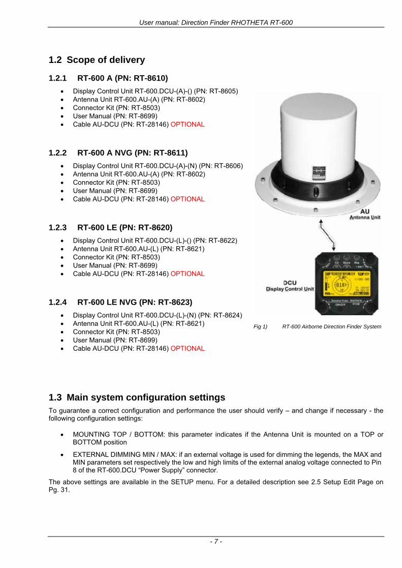
User manual Direction Finder RHOTHETA RT-600
- 7 -
12 Scope of delivery
121 RT-600 A (PN RT-8610)
Display Control Unit RT-600DCU-(A)-() (PN RT-8605) Antenna Unit RT-600AU-(A) (PN RT-8602) Connector Kit (PN RT-8503) User Manual (PN RT-8699) Cable AU-DCU (PN RT-28146) OPTIONAL
122 RT-600 A NVG (PN RT-8611)
Display Control Unit RT-600DCU-(A)-(N) (PN RT-8606) Antenna Unit RT-600AU-(A) (PN RT-8602) Connector Kit (PN RT-8503) User Manual (PN RT-8699) Cable AU-DCU (PN RT-28146) OPTIONAL
123 RT-600 LE (PN RT-8620)
Display Control Unit RT-600DCU-(L)-() (PN RT-8622) Antenna Unit RT-600AU-(L) (PN RT-8621) Connector Kit (PN RT-8503) User Manual (PN RT-8699) Cable AU-DCU (PN RT-28146) OPTIONAL
124 RT-600 LE NVG (PN RT-8623)
Display Control Unit RT-600DCU-(L)-(N) (PN RT-8624) Antenna Unit RT-600AU-(L) (PN RT-8621) Connector Kit (PN RT-8503) User Manual (PN RT-8699) Cable AU-DCU (PN RT-28146) OPTIONAL
Fig 1) RT-600 Airborne Direction Finder System
13 Main system configuration settings To guarantee a correct configuration and performance the user should verify ndash and change if necessary - the following configuration settings
MOUNTING TOP BOTTOM this parameter indicates if the Antenna Unit is mounted on a TOP or BOTTOM position
EXTERNAL DIMMING MIN MAX if an external voltage is used for dimming the legends the MAX and MIN parameters set respectively the low and high limits of the external analog voltage connected to Pin 8 of the RT-600DCU ldquoPower Supplyrdquo connector
The above settings are available in the SETUP menu For a detailed description see 25 Setup Edit Page on Pg 31
User manual Direction Finder RHOTHETA RT-600
- 8 -
2 Operating Operating the RT-600 direction finder is intentionally simple due to its intuitive human machine interface All operational settings are controlled from the RT-600-DCU Display and Control Unit Of all the controls on the RT-600DCU only the PAGE knob and the ONOFF button have functions which are not dependent on the active page selected by the user
21 General Operating Principles
Fig 2) RT-600DCU Front Panel Layout
(1) gtLC Graphic Displaylt (128 x 64 dots dot-matrix display dark blue on yellow-green background)
showing all relevant operational information depending upon the selected page
(2) gtONOFFlt Push-button to switch on off the system
(3) gtMenult options for rotary and push buttons If a field with dark background and bright text is shown below a button or switch the function described in this field may be selected through the operational element above or below this menu field In case of the Page Menu the active page is high-lighted with dark background while the inactive page is in black letters
(4) gtVolumelt Rotary Switch used depending on the active page to adjust the volume of the audio output or to select frequency values (MHz steps)
(5) gtSQLlt Rotary Switch used depending on the active page to adjust the squelch function or to select specific functions on a page depending upon the interactive menu on the display
(6) Push-buttons (see next page)
(7) gtPagelt Rotary Switch Selects pages ldquoDFrdquo and ldquoFRQrdquo - Page ldquoDFrdquo for direction finder standard bearing operation - Page ldquoFRQrdquo for changing active frequency Also adjusts display brightness if used during DIMMING mode
User manual Direction Finder RHOTHETA RT-600
- 9 -
211 Push-buttons with double function
The three push-buttons (1) (2) and (3) can be used with two different effectshellip
Keypress for short-time (lt 1 sec)
(1) gtF1lt Push-button If pushed for a short time
this button activates the function F1 described in the interactive menu on the display below which depends on the active mode and settings
(2) gtF2lt Push-Button If pushed for a short time this button activates the function F2 described in the interactive menu on the display below which also depends on mode and settings
(3) gtDIMlt Push-Button If pushed for a short time it activates the display DIMMING mode(see 214 Dimming function)
Fig 3) Push buttons short-time keypress
Keypress for longer time (gt 2 sec)
(1) gtCLR lt Push-button If pushed for a longer
time this button activates the CLEAR function
(2) gtSTORElt and special key button If pushed for a longer time and when using the RT-600 LE (LAW ENFORCEMENT) version then the LoJack standard Scan page with all necessary settings is activated (fast-switchover) otherwise the Store functionality is only available at the Setup Page (see 25 Setup Edit Page)
(3) gtReplt Push-Button If pushed for a longer time (ca 3 seconds) it activates the repetition of the last valid relative bearing and signal level information
Fig 4) Push buttons longer-time keypress
User manual Direction Finder RHOTHETA RT-600
- 10 -
212 Power-On procedure
After switching on the DCU pressing the ONOFF pushbutton a startup screen is displayed for five seconds
Fig 5) Power-On Screen
(1) System Type RT-600
(2) System Version ldquo(L)rdquo for LAW ENFORCEMENT version or ldquo(A)rdquo for STANDARD version
(3) Web Address (URL)
(4) Software Revision of AU (antenna unit)
(5) Serial Number of AU
(6) Additional service and maintenance information (the two characters indicate installed options)
(7) Software Revision of DCU (display control unit)
(8) Serial Number of DCU
After five seconds the equipment switches to the operational mode (for LAW ENFORCEMENT version the LoJack Scan page is displayed as home page by default)
User manual Direction Finder RHOTHETA RT-600
- 11 -
213 Main Pages Selection
Two main modes can be selected from the DCU front panel
DF Mode Page displays all relevant operational bearing information depending on the type of signal being received
FREQ SELECTION Page allows to access and edit all pre-programmed frequency memory channels
Fig 6) Page Selection
(1) The gtPagelt rotary switch is used to select the active page
(2) The active page is highlighted with dark background
(3) The inactive page which may be selected is displayed in dark letters on bright background
214 Dimming function
The background of the LC-graphic display is equipped with an LED array and its brightness may be adjusted continuously from 5 to 100 Dimming follows an exponential curve resulting in very accurate adjustment under night conditions
Fig 7) Dimming Adjustment
(1) Pressing the gtRepDIMlt button for a short time activates the
DIMMING mode
(2) Brightness actual information in percentage from 5 to 100 in 5 steps is displayed instead of the ldquoPagerdquo field in the upper right corner of the display
(3) The gtPagelt knob is used to adjust the brightness in 5 steps left and right
The active brightness level of the display will remain stored after switching off the unit separately for day and nightNVG mode
After ca 3 sec of inactivity the display will fall back to the prior main page Dimming of legends can be adjusted in two ways
Internal dimming of legends
Internal dimming is always active If an external dimming voltage is not used or is lt 1V DC legends are dimmed in the same manner as the LC display
External (remote) dimming of legends
If the external dimming voltage is gt 1V DC the brightness of the legends is controlled by the external dimming voltage (Refer to the wiring plan and to the operatingsetup-menu description)
User manual Direction Finder RHOTHETA RT-600
- 12 -
215 Squelch Operation
The main challenge of operating a direction finder is trying to use only the signal transmitted by the target in order to calculate its bearing accurately because noise and RF disturbances will cause misleading bearing indications In order to prevent the direction finder to calculate bearing results which are due to noise and disturbances several techniques are available If a signal can be distinguished from noise or other signals by its message content (eg LoJack ID) only transmissions containing the required message content are used for bearing In other cases the squelch can be used to suppress unwanted weak signals and noise A squelch level called threshold has to be set by the user or automatically by the system All signals with strength below this threshold value will be ignored while signals with strength above this level will cause a bearing indication So for a signal to be usable for bearing calculation it has to be sufficiently stronger than noise or disturbing signals that the receiver can clearly distinguish between wanted and unwanted signals As a result of the squelch technique the receiver sensitivity is reduced to the level set by the squelch threshold decreasing the maximum distance or range to the transmitter However it might be desirable to obtain bearing information even for weak signals which are very close to the noise level In this case it will be necessary to reduce the squelch level below the noise level As soon as the modulation of a signal can be heard on the speaker it can be expected that bearing calculation is possible If the noise is randomly distributed ndash as with ldquowhite noiserdquo ndash and no other signal is received the bearing indication will also be random If the noise is not random but rather a specific disturbance the bearing indication will point to the source of the noise If there is a very weak signal ldquoburiedrdquo in the noise this signal will produce a correct bearing indication thanks to sophisticated bearing technologies used in the RT-600 system Fluctuations due to noise will be small even at low signal levels however the reaction time of the bearing indication can increase To verify if a bearing indication is due to white noise or to an internal disturbance source or if it is due to a valid signal the aircraft should make a slow turn If the bearing indication is due to an external signal eg a SAR beacon the bearing indication should compensate the changed relative flight angle Example with a bearing indication of 30deg The signal is hardly audible as it is buried in the noise The airplane makes a turn left by 60deg If the bearing indication is not changing to approximately 30deg+60deg = 90deg after a few seconds the bearing is likely to be due to noise or internal disturbances from the aircraft Note The weaker a signal is the longer it will take to change the bearing Durations around 5 seconds are not unfamiliar in such cases Therefore it is not useful to use this procedure for signals with short transmission times and low transmit duty cycles such as COSPAS-SARSAT transmission The procedure is best suited for ELT transmission with a continuous signal and still well-suited for ELTs with intermittent transmission (down to 33) In cases where pulsed signals are to be received the receiver is able to decide automatically which squelch level is best-suited for normal operation In such cases an automatic (ldquoArdquo) squelch is provided The threshold is automatically set to a value higher than the calculated noise level The difference in dB between noise and threshold level can be defined in the Setup Menu Refer to the chapter ldquoSetup Pagerdquo for details During AUTO squelch operation the user has the possibility to force the squelch into MANUAL mode but needs to be aware of the operational limitations described in this chapter In cases where the Antenna Unit checks signal validity autonomously and without useful possibilities of user interaction user interaction is not possible and the squelch purely follows internal rules appropriate to the type of signal received
User manual Direction Finder RHOTHETA RT-600
- 13 -
Examples of different squelch settings
Fig 8) Manual squelch mode correct squelch
adjustment
Correct squelch adjustment If the squelch is set to level (b) slightly over the noise level (a) the receiver audio output remains quiet and no wrong noisy bearing is indicated
Fig 9) Manual squelch mode Incorrect squelch
adjustment
Incorrect squelch adjustment If the squelch level is set (b) below the noise level (a) a wrong noisy bearing is indicated
Fig 10) Automatic squelch mode
Automatic squelch mode Automatic squelch mode is indicated by an ldquoArdquo (c) above the squelch level marker Depending on the SN-Ratio setting the squelch level is automatically set slightly higher than the noise level Using the SQL rotary switch (1) the user can change to manual squelch mode Automatic squelch mode can be activated again by setting the squelch level manually to lt 0 or gt 60
Fig 11) Automatic squelch mode with strong signal
Automatic squelch mode with strong signals Strong short receive signals will not modify the squelch level setting
Fig 12) Automatic squelch mode and not adjustable by
the user
Automatic squelch mode level not re-adjustable by user When the squelch is adjusted automatically by the system and the user is not allowed to change it an ldquoXrdquo (c) is displayed above the squelch level marker
User manual Direction Finder RHOTHETA RT-600
- 14 -
22 Frequency (FRQ) Selection Page The Frequency Selection (FRQ Selection) Page allows the user to select a frequency select a band and edit a frequency
Open FRQ Page
From the ldquoDFrdquo standard page activate the Page Rotary Switch in any direction to open the ldquoFRQrdquo Page for Frequency Selection
Fig 13) Open FRQ Page
Fig 14) FRQ ndash Frequency Selection Page
221 Selecting a Frequency
(1) Use the Page knob ldquoFRQrdquo again to select (recall) a frequency from
gtMEMlt four (4) memory channels gtWlt one (1) working (operating) frequency gtFIXlt fixed frequencies gtCPSARlt seven (7) COSPAS-SARSAT channel groups
(2) The actual adjusted frequency
(3) Frequency band-information
Exit Frequency dialogue
(4) Press push-button gtF1lt ldquoEXITrdquo to exit to DF mode (using the actual frequency
222 Recalling and editing frequencies from a memory channel
Recall
(1) With changing the Page rotary knob memory channels 1 4 can be selected The gtmarkerlt symbol indicates the actual memory channel
Edit
(2) MHz plusmn edits the MHz Value of the actual frequency
(3) kHz plusmn edits the kHz Value of the actual frequency
(4) F2 switches to next band
gtMHzlt and gtkHzlt directly changes and overwrites the actual selected memory frequency inside the actual band (see also 224 Editing a Frequency)
Fig 15) Recall frequency of Memory channel 3
User manual Direction Finder RHOTHETA RT-600
- 15 -
223 Recalling frequencies from fixed frequencies or CospasSarsat Channels
Fig 16) FRQ Selection Page with FIX1 selected
(1) ldquoFIXrdquo Selection range for fixed frequencies
for RT-600 Standard version for RT-600 Law Enforcement version
FIX1 ldquoEltPlbrdquo 121500 MHz international VHF air distress emergency frequency
FIX2 ldquoChnl16rdquo 156800 MHz marine VHF emergency radio channel 16
FIX3 ldquoEltMILrdquo 243000 MHz military UHF air distress emergency frequency
FIX1 ldquoEltPlbrdquo 121500 MHz international VHF air distress emergency frequency
FIX2 ldquoChnl16rdquo 156800 MHz marine VHF emergency radio channel 16
FIX3 ldquoLE(USA)rdquo 173xxx MHz LoJack Recovery System
FIX4 ldquoETSSTDrdquo 216487 MHz ETS standard frequency
FIX5 ldquoETSUCVrdquo 216512 MHz ETS ucover frequency
(2) ldquoCPSARrdquo Selection range for Cospas Sarsat channel groups
CPSAR1 ldquo022-028rdquo 406022 hellip 028 MHz Channel A B C
CPSAR2 ldquo031-037rdquo 406031 hellip 037 MHz Channel D E F
CPSAR3 ldquo040-043rdquo 406040 hellip 043 MHz Channel G H
CPSAR4 ldquo046-052rdquo 406046 hellip 052 MHz Channel I J K
CPSAR5 ldquo055-061rdquo 406055 hellip 061 MHz Channel L M N
CPSAR6 ldquo064-070rdquo 406064 hellip 070 MHz Channel O P Q
CPSAR7 ldquo073-076rdquo 406073 hellip 076 MHz Channel R S
User manual Direction Finder RHOTHETA RT-600
- 16 -
224 Editing a Frequency
While on the FRQ SELECTION Page the user can directly edit the frequency displayed
Fig 17) FRQ Selection Page before frequency editing
(1) gtMHzlt Rotary switch for direct adjustment of the displayed MHz range inside the actual band
(1 x step = 1 MHz adjustment)
(2) gtkHzlt Rotary switch for changing the displayed kHz frequency according to the actual band frequency grid (as example 8333 kHz at the VHF airband)
(3) gtF2lt Adjustment of the next available band (see next page gtgt Selecting a Frequency Band)
Fig 18) FRQ Selection Page after frequency editing
If the selected and marked frequency is not one of the MEM [14] channels then the changed frequency is automatically stored in the work frequency WorkFRQ channel
User manual Direction Finder RHOTHETA RT-600
- 17 -
225 Selecting a Frequency Band
While on the FRQ Selection Page each available band can be selected by pressing F2 BAND
(1) Press push button F2 BAND for
switch over to the next band
(2) Designation of actual selected band
(3) Max frequency limits of the actual selected band (depends on wide band options)
Fig 19) FRQ Selection Page (bands)
Frequency bands availability depends on the system version (A LE) and its wide band options (F1 to F4) These optional wide bands are available if ordered in addition to the default bands Here is a listing of DEFAULT and OPTIONAL bands available with each version of the system RT-600 (STANDARD) Listing of bands
Default bands available OPTIONAL extended bands available
Band designation Frequency limits Option Designation Frequency limits
VHF Emergency Band 118000 hellip 124000 MHz gt F1 VHF Air Band 118000 hellip 136992 MHz
VHF Marine Band 154000 hellip 163000 MHz gt F2 Extended VHF Marine 137000 hellip 224995 MHz
UHF Emergency Band 240000 hellip 246000 MHz gt F3 UHF Air Band 225000 hellip 399975 MHz
COSPAS SARSAT 400000 hellip 406092 MHz
UHF FM Band 406100 hellip 410000 MHz gt F4 Additional UHF FM 406100 hellip 470000 MHz
RT-600 (Law Enforcement) Listing of bands
Default bands available OPTIONAL extended bands available
Band designation Frequency limits Option Designation Frequency limits
VHF Emergency Band 118000 hellip 124000 MHz gt F1 VHF Air Band 118000 hellip 136992 MHz
VHF Marine Band 154000 hellip 163000 MHz gt F2 Extended VHF Marine 137000 hellip 163000 MHz
LoJack 164000 hellip 174000 MHz
ETS 216000 hellip 220000 MHz
COSPAS SARSAT 400000 hellip 406092 MHz
User manual Direction Finder RHOTHETA RT-600
- 18 -
23 Direction Finder (DF) Mode Direction Finder (DF) mode is generally used to display all valid information processed by the DF from the signal received from a target transmitter The amount and kind of information displayed by the DCU depends on the type and content of the signal received and processed by the DF Simple signals such as the analog sweep-tone modulation received from a SAR beacon (ELT PLB EPIRB PDD) on 121500 MHz allow displaying only basic bearing information while digital signals such as COSPAS-SARSAT and LOJACK allow displaying more information for ex beacon IDs GPS coordinates codes VLUs etc
231 Operating Elements in DF Mode
Fig 20) Operational Elements in DF Mode
This picture shows the DCU operating in DF Mode on the international emergency frequency 121500 MHz
with an active signal being received (1) gtFREQUENCYlt Rotary switch activates the ldquoFRQrdquo frequency page for changing and selecting the
active frequency The last selected frequency remains stored after switching offon the device The selected frequency is shown on the graphic display bottom right Above additional information for the selected frequency is displayed The use of the rotary switch activates a sub-page Please refer to the Frequency Selection section for details
(2) gtVOLUMElt Rotary switch to adjust the audio output level The volume of a linked external speaker or amplifier can be adjusted in a range from 0 (off) to 99 (maximum loudness) The selected volume is shown in the bottom left corner of the graphic display The volume remains stored after switching offon the device
(3) gtSquelch Levellt adjusts the squelch level The squelch level has to be above the receiving level without signal (noise) Only signals above the squelch level are audible in the loudspeaker and used by the direction finder for bearing indication The gtSQLlt rotary switch allows to select the squelch threshold ie a minimum signal strength of an incoming signal to be processed The current settings on a signal level scale from 0 to 60 is shown in bright letters on dark background below the SQL rotary switch and as an arrow beside the signal Strength Bar-Graph
(4) The gtCLRlt Push-button is used for erasing the internal bearing value averaging store and the Last Signal Timer To activate this function the push-button has to be hold down for a minimum of circa two seconds The sophisticated averaging store increases bearing precision and enables at all an usable
User manual Direction Finder RHOTHETA RT-600
- 19 -
bearing display in case of bad receiving signals (if there is a far away transmitter andor temporary complete loss of a receiving signal) Caused by the averaging procedure a drag error may occur which might be disturbing the bearing indication after a quick change of course of the aircraft or vehicle In this case the indicated bearing value lags by the real bearing value for about two seconds (for very weak signals even longer) By pressing this push-button after a quick change of course the display will show the new bearing value without drag error Additionally the F1CLR Push-Button is used to activate specific functions high-lighted in the menu below the button by pushing it for a short time (here as example ldquoSCANrdquo starts scanning the actual air band)
(5) gtSTORElt push-button Without function except if a special function is high-lighted in the menu line of the display
(6) gtREPEATlt Push-button when pressed and hold for min 3 sec the last valid bearing value with corresponding receiving level is displayed
232 Standard Display in DF Mode
Fig 21) DF Mode
(1) gtRelative Bearing valuelt by means of a sophisticated averaging procedure a steady display is
accomplished as graphic display and as text in the range of 0deghellip 359deg (0deg corresponds to bearing direct ahead)
(2) gtSpreadlt maximum deviation of un-averaged bearing values This is an indicator of bearing quality The wider the range between the directions of maximum deviation the worse the received signal is As a result of the excellent averaging procedure even with a spread of 45deg good bearing results are achieved
(3) gtReceiving levellt (field strength) of the signal as a relative percentage value visualized as bar-graph indication and as decimal value Even without a received signal a certain noise level may be displayed
(4) gtSquelch levellt (independently adjustable and stored for each frequency band) Squelch level is indicated as marker at the Signal Strength Bar-Graph or as direct relative level value A usable bearing analysis can only be achieved if the squelch level is above the noise level (without received signal) If the antenna unit is placed close a heavily disturbing electronic devices the squelch level has to be raised thus making the direction finder being less sensitive In receive modes where the squelch level is set automatically an ldquoArdquo above the marker indicates the ldquoAutosquelchrdquo functionality
(5) gtLast Signallt timer showing the time since a signal has been received for the last time (ie since a signal has been stronger than the squelch level) Values are ldquominutes secondsrdquo
User manual Direction Finder RHOTHETA RT-600
- 20 -
233 Special Options in COSPAS-SARSAT DF Mode
Especially for the use together with beacons transmitting a data signal according to COSPAS-SARSAT specifications in the 406-MHz-Band special functionalities and pages are being provided After selection of a COSPASSARSAT Frequency (Refer to the chapter ldquoFrequency selection Pagerdquo) the bearing page provides additional information and operating options
Fig 22) Operational Elements and Display in COSPAS-SARSAT DF Mode
(1) gtAuto Squelchlt indication indicating that the squelch level is set automatically to be close to the noise
floor It is recommended to always use the Auto Squelch during COSPAS-SARSAT operation This can be achieved by manually selecting 0 (lowest possible value) or 60 (highest possible value) as squelch level During COSPAS-SARSAT-Operation this will force the automatic setting of the level
(2) gt121500lt menu option The COSPAS-SARSAT signal in the 406 MHz band is transmitted only every 50 seconds in form of a short data burst of 440 or 520 ms approaching the transmitter it will be received earlier than the 121500 MHz continuous signal due to its high transmitter power However in a lower distance to a transmitter bearing on 121500 MHz is faster thanks to the continuous or rapidly intermittent signal The 121500 MHz menu option allows a direct switch-over to 121500 MHz Direct return back from 121500 to the COSPAS-SARSAT band is possible from the 121500 MHz bearing Window in COSPAS-SARSAT mode Please refer to the chapter ldquo121500 MHz bearing Window in COSPAS-SARSAT moderdquo for details
(3) gtDecodelt menu option allows to open the COSPASSARSAT Decode sub-page by shortly pushing the F2 push-button above the menu option
(4) gtFrequency rangelt indication COSPAS-SARSAT is using a channel spacing of 3 kHz for its beacons Due to the internal architecture of the direction finder it is possible to receive more than one channel in the same time Thus frequency steps of the direction finder are 833 kHz instead of 3 kHz The receive frequency covered by the current receive frequency setting is shown in the display line above the receive frequency indication
Important If the exact frequency of the COSPAS-SARSAT beacon is unknown it is strongly recommended to use the COSPAS-SARSAT scanning functionality in order to detect the correct frequency (Refer to the chapter ldquoFrequency selection Pagerdquo amp ldquoCOSPAS-SARSAT Scan Moderdquo)
User manual Direction Finder RHOTHETA RT-600
- 21 -
234 COSPAS-SARSAT Decode Window
The COSPAS-SARSAT Decode Window allows decoding incoming COSPAS-SARSAT data messages Only while this decode window is activated the decoding is possible An already received COSPAS-SARSAT puls while DF bearing mode was activated can not be used for decoding afterwards In this case the user has to wait while this decode window is active for the next transmitted puls approx 50 sec later
Fig 23) COSPAS-SARSAT Beacon Information Page
(1) gtExitlt push button (F1 button) allows to exit the decode window and switch back to the COSPAS-
SARSAT DF Mode page
(2) gtSARSATlt in the upper right corner of the display indicates that the COSPAS-SARSAT decode function is activated
(3) gtCountrylt displays the COSPAS-SARSAT Country Code coded into the received data message
(4) gtLast Signallt time since the last COSPAS-SARSAT message has been received in minutes secondsrsquo format
(5) gtPositionlt field showing in case of location protocols being used by the beacon the encoded GNSS position data (latitude longitude) transmitted by the beacon
(6) gt15-HEX-IDlt 15-HEX-ID of the beacon in hexadecimal format
(7) gtData stringlt of the bits 25 to 112 of the COSPAS-SARSAT data burst in case of short messages and bits 25 to 144 in case of a long message format The last 8 Hex Values are separated by a blank Bit- and Frame-synchronization hex values (Bits 1 to 24) are suppressed to increase the readability of the data message
(8) gtXlt sign to indicate that the Squelch is controlled by the antenna unit for optimum sensitivity The user has no access to the Squelch setting
User manual Direction Finder RHOTHETA RT-600
- 22 -
235 Tracking 121500 MHz while in COSPAS-SARSAT Mode
While in COSPAS-SARSAT DF Mode the user can switch to 121500 MHz in order to track the beacon in VHF If a valid signal is not received in 121500 MHz the user can switch back to the last active COSPAS-SARSAT channel (406 MHz frequency) being tracking previously
Fig 24) Tracking 121500 MHz while in COSPAS-SARSAT Mode
Differences are (1) gt406xlt press F1 to switch back to the last
COSPAS-SARSAT channel (406 MHz frequency) being tracking previously
(2) gt121500 MHzlt Actual frequency being tracked
User manual Direction Finder RHOTHETA RT-600
- 23 -
236 COSPAS-SARSAT Scan Mode
If the COSPAS-SARSAT Scan Mode has been selected at the frequency selection page ldquoFRQrdquo the COSPAS-SARSAT channels as selectable manually from the Frequency Selection Page are scanned After reception of a COSPAS-SARSAT Signal the scanning is stopped at the received frequency Due to the fast scanning ndash the complete COSPAS-SARSAT sub-band is scanned within less than 400 ms ndash detection of a receivable COSPAS-SARSAT signal is possible within one COSPAS-SARSAT repetition cycle
Fig 25) FRQ Selection Page with SCN COSPAS-SARSAT Scan Page selected
At the frequency selection page an active COSPAS SARSAT scanning can be stopped by de-activating it with the rotary button (1) While the scanning is active it is also possible by pressing gtF1lt ldquoEXITrdquo to switch back to the DF pagehellip
Fig 26) DF page with active COSPAS-SARSAT Scan Mode at the DF page
(1) gtSCANlt flashing indication notifying the user that the equipment is operating in scan mode
(2) Frequency display indicating the COSPAS-SARSAT scanning frequency range
(3) gtXlt sign showing that squelch settings are controlled autonomously by the receiver
Scan mode can be left by pressing gtF1lt ldquoSTOPrdquo
User manual Direction Finder RHOTHETA RT-600
- 24 -
237 Marine Ship Scan Mode
Fig 27) DF Mode FRQ = 156800 MHz F1 for scan function
If the active frequency (2) is within the VHF Marine Band a fast scan of all ship channels is possible by pushing gtF1lt ldquoSCAN (1) In this scanning mode all marine channels 1 to 88 (156025 to 157450 MHz) are scanned continuously until a signal is received To offer the best monitoring functionality for the user also signals between to channels (4) are detected (scanning without gap) In order to prevent the scan to stop on noisy frequencies it is recommended to start scanning with high squelch settings You can reduce the squelch level in steps until the scan stops on a noisy frequency for the first time Then increase the squelch level slightly This will result in the highest possible scan sensitivity and avoiding noisy channels due to RF disturbances sometimes generated by other equipment in own aircraft
Fig 28) DF Mode active scanning in process
The scanning is stopped by pressing gtF1lt ldquoSTOPrdquo (3)
User manual Direction Finder RHOTHETA RT-600
- 25 -
24 Law Enforcement Operation Law enforcement special ops and other organizations use the RT-600 LE (LAW ENFORCEMENT) version instead of the RT-600 A (STANDARD) version One of the reasons is that the LE version features scanning and tracking of signals like LoJack and ETS as well as signals in the 216000 MHz ndash 220000 MHz band such as medical beacons wristankle transmitters cashasset recovery ldquotagsrdquo etc However the LE version shares many functions in common with the A version such as scanning and tracking in the AIR band COSPAS-SARSAT band etc
241 Power-On procedure
The power-on procedure is the same as described in 211
(1) System Version ldquo(L)rdquo for LAW ENFORCEMENT version
Fig 29) STARTUP Screen (see 211 for details)
242 LoJack Scan Mode Start scanning for a VLU Code
For the convenience of Law Enforcement and other special ops users who frequently engage in tracking SVRS (Stolen Vehicle Recovery System) signals such as LoJack (LoJack Corp FCC 9020 Part 2 SVRS) RHOTHETA has optimized the power-on procedure of the RT-600 LE version so that right after the STARTUP screen the unit displays automatically the LoJack Scan Mode page to start immediately scanning for a valid VLU (Vehicle Location Unit) code without pressing any key
Fig 30) LoJack Scan Mode unit is scanning for a LoJack VLU Code
(1) gtscan LoJacklt DF is scanning for any new LoJack VLU Code
(2) gtEXITlt press F1 to exit and switch directly to DF Mode
User manual Direction Finder RHOTHETA RT-600
- 26 -
243 LoJack Scan Mode from any other page
While operating on any page other than the LoJack Scan page the user can switch directly to LoJack Scan Mode by pressing Hotkey F2 for 2 secs
(1) press Hotkey F2 for 2 secs to switch to the LoJack Scan page
Fig 31) Hotkey F2
User manual Direction Finder RHOTHETA RT-600
- 27 -
244 Manual activation of LoJack Scan Mode
(1) select the LoJack frequency (see also Frequency Selection Page)
(2) press F1 to switch back to the DF MODE
Fig 32) FRQ Selection Page FRQ = LoJack BAND = LoJack (164-174 MHz)
While in DF MODE with adjusted LoJack frequency the user can switch directly to the LoJack Scan by pressing gtF1lt ldquoSCANrdquo
(1) press F1 SCAN to switch to the LoJack Scan page
(2) still no LoJack ID filter used (ID=off) all transmissions are received on the active frequency as example also unwanted tower pulses
Fig 33) DF Mode with LoJack filter OFF
User manual Direction Finder RHOTHETA RT-600
- 28 -
245 Receiving and accepting a new VLU Code
While in LoJack Scan Mode waiting for a VLU Code if a new VLU Code is displayed the user can accept it and switch directly to DF Mode by pressing F2
(1) a new LoJack VLU Code (0001A) has been received
(2) press F2 to accept the new VLU Code (0001A) and switch to DF MODE page with the LoJack filter activated to track only 0001A
Fig 34) LoJack Scan Mode with new VLU Code received
246 Entering a new VLU Code manually
While in LoJack Scan Mode the user can enter a LoJack VLU code also manually
(1 2 3) use the SELECTplusmn and plusmnVALUE knobs to enter a new LoJack VLU Code active ID (0001A)
(4) Press F1 to accept the new VLU Code and switch to DF Mode with the LoJack filter ON to track only 0001A
Fig 35) LoJack Scan Mode with new VLU Code entered manually
User manual Direction Finder RHOTHETA RT-600
- 29 -
247 Tracking one VLU Code while monitoring new VLU Codes
While on DF Mode and tracking a VLU Code (0001A) the user can turn the LoJack switch OFF with F2 also the user can start scanning all VLUs again with F1
0001A is displayed as the active VLU Code filter function is ON only 0001A is tracked
Monitoring of other VLU Codes is active in the background
(1) Press F1 to switch to the LoJack Scan Mode to scan for new VLU Codes
(2) Press F2 to switch LoJack filter OFF
Fig 36) DF Mode with active VLU Code and LoJack filter ON
248 Tracking one VLU Code and receiving a new VLU Code
While on DF MODE page and tracking VLU Code (0001A) in the background a new VLU Code is received and decoded (G2HC7)
(1) The new VLU Code is announced (NEW G2HC7)
(2) Press F1 to switch to LoJack Scan Mode to see the arrival time of G2HC7 and the possibility to change bearing to this new G2HC7
Fig 37) DF Mode with active VLU Code and announcement of new VLU Code
User manual Direction Finder RHOTHETA RT-600
- 30 -
249 Switching to a new VLU Code
While on the LoJack Scan Page tracking one VLU Code (0001A) and notified of a new VLU Code (G2HC7)
(1) press F1 to continue tracking 0001A
(2) press F2 to start tracking G2HC7
(3) Time elapsed since G2HC7 was last received
(4) Time elapsed since 0001A was last received
If F1 is pressed for 2 sec the indicated VLU Code (G2HC7) and ID (0001A) are deleted
Fig 38) LoJack Scan Page with one active VLU Code and one new VLU Code
2410 ldquoBlockingrdquo function of one LoJack VLU Code
The LoJack scan page can also be used to ldquoblockrdquo one unwanted LoJack VLU ID signal by separating the adjusted active ID from any other received LoJack VLU signal This is done by muting the audio (see example below) when a LoJack signal with VLU code ldquo0001Ardquo is received gtgt Any new VLU Code (active LoJack signal) - except for 0001A ndash will be displayed on the top row and generate the audible beep tone
Fig 39) LoJack Scan Page with one active VLU Code and audio OFF
Tip ldquoBlockingrdquo is an important tool for practical missions As example a stolen vehicle with VLU ID ldquo0001Ardquo was tracked in the DF bearing mode The mission
is completed but the VLU is normally still transmitting With the settings above only new VLU signals except the now unwanted ldquo0001Ardquo are audible and displayed in the upper (scan LoJack hellip for new VLU) box
User manual Direction Finder RHOTHETA RT-600
- 31 -
2411 Tracking in the 216 to 220 MHz band
The RT-600 features scanning and bearing functionality in the 216000 MHz to 220000 MHz band The 216000 MHz ndash 220000 MHz band contains frequencies and signals used by special services and tracked by law enforcement special ops and similar organizations These are some of the frequencies and services in this band
CFR 90259 tx 216000 MHz to 220000 MHz
Low Power Radio Service (LPRS) tx 216000 MHz to 217000 MHz
Medical beacons Project Lifesaver tx wristankle tx 213000 MHz to 216000 MHz
ETS tx stolen cashasset recovery tx ldquobaitrdquordquotagrdquo tx 216000 MHz to 220000 MHz tx = transmitter(s) However any future or current user of the Rhotheta RT-600 must be aware that tracking signals on the frequencies listed above may be challenging and even frustrating due mostly to negative factors in some of the transmitters
bull Very low RF power output
bull Inefficient antennas
bull Battery-powered devices with a ldquolow batteryrdquo condition
bull Devices worn or located in conditions of poor RF propagation
bull Devices with channel spacing different than the one specified for the RT-600
These factors can make it very difficult for the DF to receive the signal andor display an accurate bearing Disclaimer For the reasons explained above and even though the RT-600 features top performance in its class RHOTHETA does not offer - and is not to be held responsible for - any guaranteed minimum range or distance to a transmitter in this band
25 Setup Edit Page System settings are displayed in the setup page The functions described in this section should be used by trained personal only
Fig 40) Accessing the Setup Page
The setup page can be accessed by holding down the gtCLRlt (1) and gtREPlt (2) buttons simultaneously and in the same time performing a left-hand turn on the gtPagelt rotary switch (3)
User manual Direction Finder RHOTHETA RT-600
- 32 -
Fig 41) Setup Page
(1) gtStorelt push-button must be pressed in parallel if a value of a setting shall be modified If a value can
be modified the background stops to blink
(2) gtSelectlt rotary switch used to scroll through the menu options The value of the actually activated menu option is high-lighted with dark background and blinking
(3) gtValuelt rotary switch used to change values in menu options (gtStorelt (1) has to be pressed in parallel if a value shall be modified)
(4) gtSN-Ratiolt menu option representing the necessary Signal-To-Noise-Ratio (Difference between signal and noise level) used as criterion for the automatic squelch function Please refer to the chapter ldquoSquelch Operationrdquo for details Default value is 60 dB
(5) gtMounting Positionlt menu option to select Top- or Bottom-Mounting of the DF antenna In case of rooftop installation (eg on land vehicles) ldquoToprdquo shall be selected In case of bottom-down (upside-down) installation (eg on a helicopter) ldquoBotrdquo shall be selected If this option is not selected correctly all bearing values will be mirror-inverted
(6) gtBearing Offsetlt menu option to include a constant offset correction to the bearing indication Bearing values in degrees will be changed according to the offset value
(7) gtMaximum External Dimming Voltage for Legendslt menu option which sets the upper limit of the dimming input voltage for the legends-panel Range=[15 hellip 28]V
(8) gtMinimum External Dimming Voltage for Legendslt menu option which sets the lower limit of the dimming input voltage for the legends-panel Range=[15 hellip 28]V
(9) gtPagelt rotary switch to be turned right-hand to go back to the Direction Finder page A left-hand turn on this rotary switch will show up an additional service page with debug information used for system checks
(10) gtExtended Seriallt It is possible to enable or disable the extended serial data protocol Only of interest if serial data is used by any connected control units like moving maps or computers For detailed information see (Serial interface data protocol (short description)gt at page 46) If there are compatibility problems with already existing older remote control software it is recommended to switch OFF the extended serial data protocol
User manual Direction Finder RHOTHETA RT-600
- 33 -
3 Error messages If an internal error of the device is recognized a corresponding flashing error message will be shown in the DF pages
Fig 42) Error Messages
(1) Error message including error code (in brackets)
(2) Short description of the indicated error
In case of coincidence of various errors the error with the highest priority will be displayed
Error message Error location Reason
Error (12) VOLTDU
Main voltage supply Main Voltage input too low ( 100 V)
Error (11) NO AU
Connection antenna display or Antenna Unit
No serial data (RS485) from Antenna Unit No or damaged connection between antenna and display or damaged antenna unit
Error (10) BAD AU
Connection antenna display
Incompatibility or bad data connection between display and antenna
Error (9) BAD RU
Remote Unit Incompatibility or bad data connection between display and external serial Remote Unit or PC
Error (8) VOLTAU
Antenna Unit Voltage supply at Antenna Unit too low ( 90 V) Main voltage supply too low or considerable drop of voltage between display and antenna
Error (7) BAD DCU
Connection Display Antenna
Incompatibility or bad data connection between antenna and display
Error (6) NO DCU
Connection Display Antenna
No serial data from Display Control Unit to Antenna Unit
Error (5) PLL ERR
antenna Error in synthesizer-oscillator of receiver in Antenna Unit
Error (4) FRQ+OFS
received transmitter Received frequency too high (more than 6 KHz error of transmitter)
Error (3) FRQ-OFS
received transmitter received frequency too low (more than 6 KHZ error of transmitter)
Error (2) DECODE
radio distance transmitter DF
Data Bits of decoded signal (COSPAS-SARSAT or LoJack) defective
Error (1) DATARNG
Incompatibility of data DCU AU
Protocol data bytes out of valid range
Error (0) NO REC
Antenna Unit receiver
Receiver board defective
User manual Direction Finder RHOTHETA RT-600
- 34 -
4 Installation
41 Antenna unit A convenient position of the monopole bearing antenna is crucial for good bearing results The antenna needs an effective ground connection to the body of the aircraft or to the roof of the vehicle If there is no metallic mounting surface available a metallic sheet or similar (net) with connection to ground has to be applied first between vehicle-body and antenna In this hatched area the antenna touches the body ofthe vehicleaircraft In order to obtain a good groundconnection the surface of the body should be bared(Measuring unit [mm])
8 x holes for mounting the antenna unit to the
vehicle aircraft
Fig 43) Antenna Mounting Drawing
User manual Direction Finder RHOTHETA RT-600
- 35 -
411 Influence of antenna location and environment on the bearing accuracy
Recommendations concerning the practical antenna unit location on helicopters and airplanes
The bearing accuracy of the direction finder antenna unit is severely influenced (comparable to an airspeed sensor) by the environment For comparison a perfect high quality speed sensor will not indicate the true airspeed if this sensor is interfered by strong turbulences The direction finder antenna unit acts as a sensor for electromagnetic waves In the near field of this antenna unit any conductive (eg metallic) obstacle will influence the incoming wave field and create reflections which decrease the bearing accuracy These are general physical limitations concerning all types of direction finder systems To achieve the best bearing results it should be considered that the antenna unit is installed as far away as possible from any other vertically polarized conductive structure If possible there should be no reflectors within an area of 2-3 feet around the antenna unit In this worst case example the direction finder will not work properly
Fig 44) Antenna Installed in a Bad Location
In this example the antenna unit is located too close to the cable cutter of the helicopter This cutter will produce strong reflections especially as the length is equal to Lambda4 within the VHF airband
User manual Direction Finder RHOTHETA RT-600
- 36 -
Examples of properly installed direction finder antenna units
Fig 45) Antenna Installed in Good Locations
User manual Direction Finder RHOTHETA RT-600
- 37 -
42 Display and Control Unit
The display control unit may be mounted into a front panel by the means of this mounting drawing
Fig 46) DCU Mounting Drawing
(all dimensions in [mm]) To install or uninstall the display control unit perform the following steps (1) Remove the cover caps of the four rotary switches
(2) Loose the screws visible below the position of the cover caps
(3) Remove the plastic button from the axis of the four rotary switches
(4) Mount dismount the display control unit
(5) Re-install the plastic buttons on the axis of the four rotary switches
(6) Fix the screws so that the plastic buttons are fixed on the axis
(7) Re-install the cover caps on the four rotary switches
User manual Direction Finder RHOTHETA RT-600
- 38 -
43 System Interconnect Wiring Diagram (Also refer to chapter ldquoTechnical Datardquo for details)
Fig 47) System Interconnect Wiring Diagram
6-pol Amphenol plug femalePTG06SE10-6S(SQ)
max length of cable 20 m 9-pol Sub-D plug (femalemale)
User manual Direction Finder RHOTHETA RT-600
- 39 -
5 Technical Data
51 Electric features
Method of bearing Doppler-principle (3 kHz rotational frequency right left rotation)
Bearing accuracy1 plusmn 5deg RMS
Internal resolution 1deg
Bearing Sensitivity VHF AirEmergency le 25 μVm (typical)
VHF Marine le 25 μVm (typical)
UHF Emergency and ETS le 4 μVm (typical)
COSPAS-SARSAT le 4 μVm (typical)
LoJack Decoding (50 Message Error Rate) and bearing le 5 μVm (typical)
Frequency stability plusmn 20 ppm (Δff = plusmn210-6)
Reception frequencies
SAR version (Standard)
Frequency Options
VHF Emergency Band 118000 to 124000 MHz (833 kHz steps AM)
VHF Marine Band 154000 to 163000 MHz ( 500 kHz steps FM) (channel 16 selectable via channel no)
UHF Emergency Band 240000 to 246000 MHz (2500 kHz steps AM)
UHF FM Band 406100 to 410000 MHz ( 500 kHz steps FM)
COSPAS-SARSAT 400000 to 406092 MHz Including 406022 to 406076 MHz (Channel A S)
F1 VHF Air Band 118000 to 136992 MHz
F2 extended VHF Marine Band 137000 to 224995 MHz
F3 extended UHF Air Band 225000 to 399975 MHz
F4 additional UHF FM Band 406100 to 470000 MHz
Reception frequencies
LAW Enforcement version
Frequency Options
VHF Emergency Band 118000 to 124000 MHz (833 kHz steps AM)
VHF Marine Band 154000 to 163000 MHz (500 kHz steps FM) (channel 16 selectable via channel no)
LoJack 164000 to 174000 MHz (125 kHz steps FM)
ETS 216000 to 220000 MHz (10125 kHz AM)
COSPAS-SARSAT 400000 to 406092 MHz Including 406022 to 406076 MHz (Channel A S)
F1VHF Air Band 118000 to 136992 MHz
F2 extended VHF Marine Band 137000 to 163000 MHz
COSPAS-SARSAT fast scan mode
Full automatic detection of any active COSPAS-SARSAT channel A to S within 400 ms
COSPAS-SARSAT decoding
Reception and decoding of COSPAS-SARSAT data signal (112 or 144 bit) specified according to COSPAS-SARSAT
LoJack decoding Selectable LoJack ID display and selective active filtering
Special scanning modes
complete maritime ship band scanning within 3 s (channel 01 hellip 88 also frequencies between 2 channels are included)
1With undisturbed wave field and sufficient field strength Measuring by changing the angle of incidence with the antenna rotating on a revolving table in order to eliminate environmental influences on the results No modulation
User manual Direction Finder RHOTHETA RT-600
- 40 -
Bearable modulation A3E F3E A3X (ELT-modulation) F1D G2D COSPAS-SARSAT Bearing largely independent of modulation
Polarization Vertical
Polarization error 5deg at 60deg field vector rotation
Garbling cone Ca 30deg to the vertical
Time of response2 50 ms (with sufficient reception field strength)
LC-graphic display 128 x 64 pixels supertwist transflective extended range of temperature dark-blue display on yellow-green background background light Freely adjustable (exponential) dimming of brightness
NVG cockpit design Fully compatible NVIS Green B display Control Unit optional
Operating voltage 275 V nominal 12 V to 35 V DC
Current consumption LCD-background light Off max 500 mA (12 V DC) max 250 mA (24 V DC)
LCD-background light 100 max 750 mA (12 V DC) max 350 mA (24 V DC)
LCD-background light 100 max 900 mA (12 V DC) with NVG Option max 400 mA (24 V DC)
Audio out For external speaker approx 2 W (4 Ω)
Serial data interface Serial interface RS-232 (9600 baud 8 data bits 1 stop bit no parity)
2Very weak signals can considerably increase the time of response
User manual Direction Finder RHOTHETA RT-600
- 41 -
52 Interface External connections (optional at Sub-D 9-pol Male connector)
Dimming
Pin 8
external voltage input for variable dimming of legends
(optional)
Analog input signal for variable control of the legends illumination Input voltage range is freely adjustable in the range of 15 hellip 28 V in the setup menu Refer to chapter ldquoSetup Pagerdquo Default setting 8 hellip28 V (8 V = Off 28 V = max dimming for legends)
Input Impedance gt 50 k
Pin 6 night status line for LCD
dimming (optional)
Low-active (as example switch to ground) At input voltage lt 25 VDC the LCD dimming operates in nightNVG mode Maximum brightness ca 4 of daydefault mode brightness
Input Impedance gt 50 k
Pin 4 NVG status line for LCD
dimming (optional)
Low-active (as example switch to ground) At input voltage lt 25 VDC the LCD dimming operates in nightNVG mode Maximum brightness ca 4 of daydefault mode brightness
Input Impedance gt 50 k
AudioLF
Pin 7 Audio output signal
AC coupled voltage source with very low inner resistance Maximum output voltage ca 8 VPP = 283V RMS at maximum Volume Maximum output power ca 2 W with 4 speaker
If a headphone is connected ([32hellip600] 100mW) we recommend using a resistor (18 025 W) between audio output and headphone to prevent damage of the headphone
Serial interface RS232 (9600 baud 8 data bits 1 stop bit no parity)
Pin 3 TXD Serial output (ca plusmn10 V)
Pin 2 RXD Serial input (ca plusmn10 V)
User manual Direction Finder RHOTHETA RT-600
- 42 -
53 Mechanical features
Temperature range
Display Control Unit permissible operating temperature3 -20 degC +60 degC permissible storage temperature -30 degC +80 degC
Antenna Unit permissible operating temperature3 -40 degC +60 degC permissible storage temperature -55 degC +80 degC
Protective system Antenna Unit IP 67
Weights Display Control Unit 250 g Antenna Unit 2000 g
Dimensions Display Control Unit 82 mm x 82 mm x 43 mm (width x height x depth) Antenna Unit 270 mm x 185 mm
Fig 48) DCU Mechanical Drawing (all dimensions in [mm])
3 For temperatures lower than ndash10deg C a warm-up period of 15 min should be allowed
User manual Direction Finder RHOTHETA RT-600
- 43 -
Fig 49) AU Mechanical Drawing (all dimensions in [mm])
User manual Direction Finder RHOTHETA RT-600
- 44 -
6 Appendix
61 Frequency Ranges
User manual Direction Finder RHOTHETA RT-600
- 45 -
62 Frequencies of channels on maritime band (only for standard [A] version) Frequency-range of the RT-600 in the maritime band 156000 MHz 162025 MHz
Channel No frequency (ship - station) Frequency (coast - station)
1 156050 MHz 160650 MHz 2 156100 MHz 160700 MHz 3 156150 MHz 160750 MHz 4 156200 MHz 160800 MHz 5 156250 MHz 160850 MHz 6 156300 MHz 160900 MHz 7 156350 MHz 160950 MHz 8 156400 MHz 9 156450 MHz
10 156500 MHz 11 156550 MHz 12 156600 MHz 13 156650 MHz 14 156700 MHz 15 156750 MHz 16 156800 MHz 17 156850 MHz 18 156900 MHz 161500 MHz 19 156950 MHz 161550 MHz 20 157000 MHz 161600 MHz 21 157050 MHz 161650 MHz 22 157100 MHz 161700 MHz 23 157150 MHz 161750 MHz 24 157200 MHz 161800 MHz 25 157250 MHz 161850 MHz 26 157300 MHz 161900 MHz 27 157350 MHz 161950 MHz 28 157400 MHz 162000 MHz 60 156025 MHz 160625 MHz 61 156075 MHz 160675 MHz 62 156125 MHz 160725 MHz 63 156175 MHz 160775 MHz 64 156225 MHz 160825 MHz 65 156275 MHz 160875 MHz 66 156325 MHz 160925 MHz 67 156375 MHz 68 156425 MHz 69 156475 MHz 70 156525 MHz 71 156575 MHz 72 156625 MHz 73 156675 MHz 74 156725 MHz 75 156775 MHz 76 156825 MHz 77 156875 MHz 78 156925 MHz 161525 MHz 79 156975 MHz 161575 MHz 80 157025 MHz 161625 MHz 81 157075 MHz 161675 MHz 82 157125 MHz 161725 MHz 83 157175 MHz 161775 MHz 84 157225 MHz 161825 MHz 85 157275 MHz 161875 MHz 86 157325 MHz 161925 MHz 87 157375 MHz 161975 MHz 88 157425 MHz 162025 MHz
User manual Direction Finder RHOTHETA RT-600
- 46 -
63 Serial interface data protocol (short description)
631 General
Interface parameters RS232 9600 Baud 8 databits 1 stopbit no parity LSB sent first Timing of serial data For accurate use of the serial data (even for the optional serial input commands) the correct timing is mandatory The DCU (Display Control Unit) sends out via the RS-232 Pins (see 43 System Interconnect Wiring Diagram page 38) cyclic and autonomous every approx 250300 ms a binary data stream which contains all relevant DF-bearing information The output data contains one or two blocks of binary data (see next picture with accordingly description) The optional serial input is only used if changes (as example frequency change) are done by additional remote control units
Fig 50) Timing of serial data
Serial standard output
This output data is always available and contains all relevant DF-bearing data For detailed content see page 47
Optional extended serial output
This data contains some additional information like as example CospasSarsat or LoJack decoding and ID data For detailed content see page 50 The data is only available with DCU Software [Rev ge 320] and if this optional data block is configured as ON = enabled (see Setup Edit Page point (10) )
Even to avoid compatibility problems with already existing older remote control software it is possible to disable switch off this additional data block (see Setup Edit Page point (10) )
Optional serial input
Only used for optional commands to control DCU parameters If as example the direction finder frequency is changed remotely there is send to the DCU one time this data block with the new frequency For detailed content see page 52
User manual Direction Finder RHOTHETA RT-600
- 47 -
632 Serial standard output (protocol description)
Specification serial standard output
The binary data stream with a length of 39 bytes starts with a header byte (value = hex 0xA0 as ID for DF Mode) The next bytes contain different values for status bearing information and also service The last byte is used for data stream checksum control Remark This is a binary data protocol So every byte value from 0dec hellip 255dec (0x00 hellip 0xFF) is possible Because of this it is not allowed to realize a start byte detection by the content (0xA0) The idle line detection is recommended for detection the end of message Register of databytes (for details see next page)
byte no
[0] Header = 0xA0 Id for DF Mode
[1] Number = 39 = bytes in the complete message (including header and checksumbyte)
[2] Status (1) HSB [x|x|x|x|x|x|x|x] LSB | | | | | | | --gt (0) Receiving | | | | | | ----gt (1) Squelch controlled by AU (X) | | | | | ------gt (2) Permission RL Calibration | | | | --------gt (3) Line Night | | | ----------gt (4) Line NVG | | ------------gt (5) Dimming External | --------------gt (6) Autosquelch Active ----------------gt (7) 0=Standard Version 1=LE Version
[3] Status (2) HSB [x|x|x|x|x|x|x|x] LSB | ----------------gt (7) 0=Standard 1=extended serial dataprotocol = ONactive
[45] Error (Bits[120])
[6] Actual DCU Page
[7] Volume [0hellip100]
[811] Frequency [Hz]
[12] Active Band
[13] Actual Squelchlevel [0hellip60]
[14] Audio-Line amp_NF_Test Output
[15] (Not used)
[1617] Voltage_DCU ([0hellip335]=[0 hellip 335]V
[1819] Voltage_AU ([0hellip255]=[0 hellip 255]V
[20] Temperature_AU [-68hellip+127]degC
[21] Frequency Offset [-99hellip+99]
[2225] ServiceTest values (mode dependent test values for service only)
26 (Not used reserved)
[27] Level [0hellip100]
[2829] Bearing Averaged [0hellip359]deg relative
[3031] Bearing Live_Min [0hellip359]deg relative
[3233] Bearing Live_Max [0hellip359]deg relative
[34] Test Value PS-RAM Right Rotation[0hellip178] (for service only)
[35] Test Value PS-RAM Left Rotation [0hellip178] (for service only)
[3637] (Not used reserved)
[38] Checksum is the 2rsquos complement of the modulo-256 sum of all bytes without checksum-byte [0n-1]
User manual Direction Finder RHOTHETA RT-600
- 48 -
Detailed Description of important values for practical use
Status byte [2] Receiving Bit 0 of this value (LSB) indicates signal receiving Bit 0 = 0 then no signal is received and so on no bearing is available Bit 0 = 1 then bearing is possible Bit 1 if(1) then Squelch is controlled by AU (active at modes CospasSarsat Decode CospasSarsat Scanning LoJack with Filter=ID only)
Error bytes [4hellip5] 16 bit value each set bit corresponds to the error no (Refer to the chapter Error messages) Example - 0x0000 No error - 0x0800 Bit No 11 Set ( = No AU Error)
Actual DCU Page byte [6] indicates actual operating mode of DCU 0 = Standard bearing page 1 = Frequency memory page 2 = CospasSarsat decoding page 3 = LoJack decoding page (ID edit)
Frequency bytes [8hellip11] 32 bit value actual adjusted frequency [Hz] Example - 0x073DF160 1215000000 121500 MHz
Active Band Standard Version [A] 0=VHF Airband 1=VHF Marineband sea 2=VHF Marineband coast 3=UHV Airband 4=CospasSarsat LE Version [L] 0=VHF Airband 1=LoJack 2=Lifesaver 3=ETS 4=CospasSarsat
Actual Squelchlevel byte [13] Range [0hellip60] without signal the actual squelchlevel should always be adjusted a little bit over the noise level (Refer to the chapter Squelch operation)
Level byte [27] Range [099] actual receiving level (without signal this value is equal to the noise level) If a signal is received then this value corresponds to the signal strength of this signal
Relative Bearing averaged byte [2829] 16 bit value Range [0hellip359 0xFFFF] if the value = 0xFFFF then no valid bearing is available otherwise this value contains the actual averaged bearing information in Deg [0deg359deg] Example - 0X0114 276deg bearing (= left side oriented to heading)
Bearing Live MinMax byte[3031] amp [3233] - 16 bit values Range [0hellip359 0xFFFF] Only for signal quality or additional information ndash NOT recommended for bearing indication The relative live bearing field contains the maxmin bearing in degrees without averaging The relative live bearing reacts faster than the normal relative bearing but it has not the precision of the averaged bearing The MinMax Bearing Values are calculated within a time period of approx 250 ms If they are very close together (for example ldquo124rdquo and ldquo128rdquo degrees) then the signal quality is quite good A wide span of the minmax values (for example ldquo97rdquo and ldquo162rdquo) shows very noisy but nevertheless bearable signal quality
User manual Direction Finder RHOTHETA RT-600
- 49 -
633 DCU Info output (protocol description)
Specification DCU Info output
Remark This protocol is only available while the SetupEdit page is activated at the DCU
byte no
[0] Header = 0xAF Id for DCU Info Mode
[1] Number = 39 = bytes in the complete message (including header and checksumbyte)
[2]
(see standard output) [3]
[45]
[621] Info String of 15 byteschars the string contains Information about Unit Variant Software Version and Serial No
Example Byte [318] =
|--AU ID---||Var-||---Software Version---| |-------------- Serial No---------------| [0x44][0x55][0x41][0x33][0x2E][0x33][0x30][0x3A][0x20][0x20][0x30][0x31][0x32][0x33][0x34][0x00] rsquoDrsquo rsquoUrsquo rsquoArsquo rsquo3rsquo rsquorsquo rsquo3rsquo rsquo0rsquo rsquorsquo rsquo rsquo rsquo rsquo rsquo0rsquo rsquo1rsquo rsquo2rsquo rsquo3rsquo rsquo4rsquo rsquoENDrsquo | | | | __________________ | | ________________________ | n n n | | n n n n n | (Software Version) | | (Serial No) | gt rsquoArsquo = Standard Variant gt rsquoLrsquo = Law Enforcement Variant
User manual Direction Finder RHOTHETA RT-600
- 50 -
634 Optional extended serial output (protocol description)
The data content depends on the actual mode of the direction finder To get special data the direction finder has first to be switched to the equivalent mode
COSPAS-SARSAT Decoding data
This data is only available and valid if Display Control Unit with actual software Rev ge 320 (see Power-On procedure page 10) Configuration of Extended serial = ON (see Setup Edit Page point (10) ) Direction Finder COSPAS-SARSAT decoding mode is activated by selecting the corresponding page
(see COSPAS-SARSAT Decode Window page 20 and page 21) and so on Header (byte 0 of data) = 0x91
A valid COSPAS-SARSAT decoding data protocol is always marked by the first data byte (header = 0x91) Always after receiving and decoding of a valid COSPAS-SARSAT pulse the complete data protocol with 33 bytes is send out one time
Byte No
[0] Header = 0x91 (Identification for CPSarsat decoding mode)
[1] Number of bytes - 7 if no decoded pulse is available - 33 if new pulse was received and is available
[2] Error
[3] Bit[0] - 0 =gt No new 406 MSG (decoded data) available - 1 =gt New valid 406 MSG available (Sync amp Frame Ok) Check Error Status for Bit-Errors
Bit[61] AutoSquelch Level valid range [060] ( decimal)
Bit[7] = 1 Squelch controlled by AU
[4] Signallevel of received signal valid range [099] ( decimal)
[5] Voltage of Antenna Unit Power Supply input valid range [80255] (decimal = 80 255 V DC)
[6] Temperature inside Antenna Unit valid range [-50+100] (degC signed byte value)
The following databytes are only available if a correct CPSarsat puls gets received and decoded with correct checksum
[724] 18 x Databytes complete orginal CPSarsat 406 decoded message (144 bit)
Databyte Nr [ Byte 7 ] [ Byte 8 ] [Byte9 Byte24] 406 MSG Bit Nr [1 2 3 4 5 6 7 8] [9 10 11 12 13 14 15 16] [17 144]
[25] SN-Flag valid values 0x53=rsquoSrsquo 0x4E=rsquoNrsquo 0x2D=rsquo-rsquo if no GPS data available
GPS-Position Latitude
[26] Deg valid values [090] (decimal Deg) 0xFF if no GPS data available
[27] Min valid values [059] (decimal Deg) 0xFF if no GPS data available
[28] Sec valid values [059] (decimal Deg) 0xFF if no GPS data available
[29] WE-Flag valid values 0x57=rsquoWrsquo 0x45=rsquoErsquo 0x2D=rsquo-rsquo if no GPS data available
GPS-Position Longitude
[30] Deg valid values [0180] (decimal Deg) 0xFF if no GPS data available
[31] Min valid values [059] (decimal Deg) 0xFF if no GPS data available
[32] Sec valid values [059] (decimal Deg) 0xFF if no GPS data available
User manual Direction Finder RHOTHETA RT-600
- 51 -
LoJack ID data
This data is only available and valid if Display Control Unit with actual software Rev ge 320 (see Power-On procedure page 10) Direction Finder of variant [L] Law Enforcement Configuration of Extended serial = ON (see Setup Edit Page point (10) ) Direction Finder is working with active LoJack gtID Filterlt Header (byte 0 of data) = 0x93 or 0x94
Valid LoJack ID decoding data is always marked by the first data byte (header = 0x93 or 0x94)
Byte No
[0] Header = 0x93 LoJack ID editing sub-page is selected Filter = VLU all valid and received LoJack pulses are indicated = 0x94 Lojack Decode amp DF Mode with active Filter = ID
[1] Number of bytes in the complete data stream - decimal 26 = default value
[2] Nonrelevant
[3] Bit[0] Receiving OnOff - 0 =gt No Receiving no bearing - 1 =gt new LoJack pulse received
[412] Nonrelevant
[1317] Lojack ID
Replay Code 5 x ASCII Chars ldquoNo BIOZrdquo set
Example ASCII = ldquo000R1rdquo
18 Receiver Level Out Max [099]
19
LoJack Decoder Status [07] - 0 Off - 1 Wait for Preamble - 2 Preamble Ok - 3 FlagPattern Ok - 4 Data BitError gt 1 - 5 Data Ok (No VLU) - 6 VLU Ok - 7 ID Ok (Filter=IDONLY)
[2025] Nonrelevant
Remark Only if byte no [3] bit [0] gets ldquo1rdquo (Receiving On) then an active LoJack pulse is received and so on the corresponding LoJack ID valid otherwise the LoJack ID only shows the actual adjusted LoJack Filter ID of the direction finder
User manual Direction Finder RHOTHETA RT-600
- 52 -
635 Optional serial input (protocol description)
Specification serial input (optional)
The serial input is normally used for service and maintenance only Nevertheless it is possible via this interface to remote control the actual frequency and the squelchlevel of the DF system If a valid data stream is send to the DF then the actual frequency selection at the DCU is switched to Block2 AUX0 At this memory channel the new frequency is stored and used automatically (Refer to the chapter Frequency Selection Page) If the frequency is changed (by one valid data stream) no more serial input is necessary The actual frequency can be changed again at any time by manual operation at the DCU The timing of serial input (if used) is strictly fixed The optional serial input has to take place directly after a complete serial output (max 50 ms delay time) If a new changed frequency is commanded to the DCU via this serial input interface it can take up to 1 sec of time until this new frequency is ready for operationbearing It is strictly not recommended to use the frequency remote control for any scan mode The frequency control has to be used for static frequency change only Register of databytes
byte no
[0] Header 0xC0
[1] Number of bytes in the complete message (including header and checksumbyte)
[23] (not used for normal operation any byte values allowed)
[4] Volume [0100]
[58] Frequency [Hz] (frequency is rounded to the according grid automatically)
Valid Range for Standard Version Valid Range for LE Version
118000000 hellip 123000000 [Hz] 8333 kHz 118000000 hellip 123000000 [Hz] 8333 kHz
156050000 hellip 162025000 [Hz] 5000 kHz 164000000 hellip 174000000 [Hz] 8333 kHz
201000000 hellip 215995000 [Hz] 5000 kHz
240000000 hellip 246000000 [Hz] 8333 kHz 216000000 hellip 218995000 [Hz] 12500 kHz219000000 hellip 220000000 [Hz] 10000 kHz
400000000 hellip 410000000 [Hz] 8333 kHz 400000000 hellip 410000000 [Hz] 8333 kHz
[9] Squelchlevel Manual = [0hellip60] Autosql= [ -1] Warning use only for pulsed signals (as example CpSarsat LoJack)
[10] (not used for normal operation any byte values allowed)
[11] Internal Dimming [0100]
[12] Checksum is the 2rsquos complement of the modulo-256 sum of all bytes without checksum-byte [0n-1]
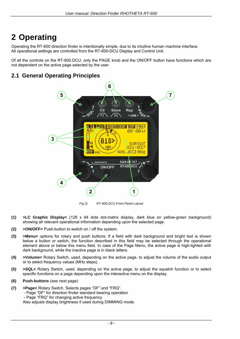
User manual Direction Finder RHOTHETA RT-600
- 8 -
2 Operating Operating the RT-600 direction finder is intentionally simple due to its intuitive human machine interface All operational settings are controlled from the RT-600-DCU Display and Control Unit Of all the controls on the RT-600DCU only the PAGE knob and the ONOFF button have functions which are not dependent on the active page selected by the user
21 General Operating Principles
Fig 2) RT-600DCU Front Panel Layout
(1) gtLC Graphic Displaylt (128 x 64 dots dot-matrix display dark blue on yellow-green background)
showing all relevant operational information depending upon the selected page
(2) gtONOFFlt Push-button to switch on off the system
(3) gtMenult options for rotary and push buttons If a field with dark background and bright text is shown below a button or switch the function described in this field may be selected through the operational element above or below this menu field In case of the Page Menu the active page is high-lighted with dark background while the inactive page is in black letters
(4) gtVolumelt Rotary Switch used depending on the active page to adjust the volume of the audio output or to select frequency values (MHz steps)
(5) gtSQLlt Rotary Switch used depending on the active page to adjust the squelch function or to select specific functions on a page depending upon the interactive menu on the display
(6) Push-buttons (see next page)
(7) gtPagelt Rotary Switch Selects pages ldquoDFrdquo and ldquoFRQrdquo - Page ldquoDFrdquo for direction finder standard bearing operation - Page ldquoFRQrdquo for changing active frequency Also adjusts display brightness if used during DIMMING mode
User manual Direction Finder RHOTHETA RT-600
- 9 -
211 Push-buttons with double function
The three push-buttons (1) (2) and (3) can be used with two different effectshellip
Keypress for short-time (lt 1 sec)
(1) gtF1lt Push-button If pushed for a short time
this button activates the function F1 described in the interactive menu on the display below which depends on the active mode and settings
(2) gtF2lt Push-Button If pushed for a short time this button activates the function F2 described in the interactive menu on the display below which also depends on mode and settings
(3) gtDIMlt Push-Button If pushed for a short time it activates the display DIMMING mode(see 214 Dimming function)
Fig 3) Push buttons short-time keypress
Keypress for longer time (gt 2 sec)
(1) gtCLR lt Push-button If pushed for a longer
time this button activates the CLEAR function
(2) gtSTORElt and special key button If pushed for a longer time and when using the RT-600 LE (LAW ENFORCEMENT) version then the LoJack standard Scan page with all necessary settings is activated (fast-switchover) otherwise the Store functionality is only available at the Setup Page (see 25 Setup Edit Page)
(3) gtReplt Push-Button If pushed for a longer time (ca 3 seconds) it activates the repetition of the last valid relative bearing and signal level information
Fig 4) Push buttons longer-time keypress
User manual Direction Finder RHOTHETA RT-600
- 10 -
212 Power-On procedure
After switching on the DCU pressing the ONOFF pushbutton a startup screen is displayed for five seconds
Fig 5) Power-On Screen
(1) System Type RT-600
(2) System Version ldquo(L)rdquo for LAW ENFORCEMENT version or ldquo(A)rdquo for STANDARD version
(3) Web Address (URL)
(4) Software Revision of AU (antenna unit)
(5) Serial Number of AU
(6) Additional service and maintenance information (the two characters indicate installed options)
(7) Software Revision of DCU (display control unit)
(8) Serial Number of DCU
After five seconds the equipment switches to the operational mode (for LAW ENFORCEMENT version the LoJack Scan page is displayed as home page by default)
User manual Direction Finder RHOTHETA RT-600
- 11 -
213 Main Pages Selection
Two main modes can be selected from the DCU front panel
DF Mode Page displays all relevant operational bearing information depending on the type of signal being received
FREQ SELECTION Page allows to access and edit all pre-programmed frequency memory channels
Fig 6) Page Selection
(1) The gtPagelt rotary switch is used to select the active page
(2) The active page is highlighted with dark background
(3) The inactive page which may be selected is displayed in dark letters on bright background
214 Dimming function
The background of the LC-graphic display is equipped with an LED array and its brightness may be adjusted continuously from 5 to 100 Dimming follows an exponential curve resulting in very accurate adjustment under night conditions
Fig 7) Dimming Adjustment
(1) Pressing the gtRepDIMlt button for a short time activates the
DIMMING mode
(2) Brightness actual information in percentage from 5 to 100 in 5 steps is displayed instead of the ldquoPagerdquo field in the upper right corner of the display
(3) The gtPagelt knob is used to adjust the brightness in 5 steps left and right
The active brightness level of the display will remain stored after switching off the unit separately for day and nightNVG mode
After ca 3 sec of inactivity the display will fall back to the prior main page Dimming of legends can be adjusted in two ways
Internal dimming of legends
Internal dimming is always active If an external dimming voltage is not used or is lt 1V DC legends are dimmed in the same manner as the LC display
External (remote) dimming of legends
If the external dimming voltage is gt 1V DC the brightness of the legends is controlled by the external dimming voltage (Refer to the wiring plan and to the operatingsetup-menu description)
User manual Direction Finder RHOTHETA RT-600
- 12 -
215 Squelch Operation
The main challenge of operating a direction finder is trying to use only the signal transmitted by the target in order to calculate its bearing accurately because noise and RF disturbances will cause misleading bearing indications In order to prevent the direction finder to calculate bearing results which are due to noise and disturbances several techniques are available If a signal can be distinguished from noise or other signals by its message content (eg LoJack ID) only transmissions containing the required message content are used for bearing In other cases the squelch can be used to suppress unwanted weak signals and noise A squelch level called threshold has to be set by the user or automatically by the system All signals with strength below this threshold value will be ignored while signals with strength above this level will cause a bearing indication So for a signal to be usable for bearing calculation it has to be sufficiently stronger than noise or disturbing signals that the receiver can clearly distinguish between wanted and unwanted signals As a result of the squelch technique the receiver sensitivity is reduced to the level set by the squelch threshold decreasing the maximum distance or range to the transmitter However it might be desirable to obtain bearing information even for weak signals which are very close to the noise level In this case it will be necessary to reduce the squelch level below the noise level As soon as the modulation of a signal can be heard on the speaker it can be expected that bearing calculation is possible If the noise is randomly distributed ndash as with ldquowhite noiserdquo ndash and no other signal is received the bearing indication will also be random If the noise is not random but rather a specific disturbance the bearing indication will point to the source of the noise If there is a very weak signal ldquoburiedrdquo in the noise this signal will produce a correct bearing indication thanks to sophisticated bearing technologies used in the RT-600 system Fluctuations due to noise will be small even at low signal levels however the reaction time of the bearing indication can increase To verify if a bearing indication is due to white noise or to an internal disturbance source or if it is due to a valid signal the aircraft should make a slow turn If the bearing indication is due to an external signal eg a SAR beacon the bearing indication should compensate the changed relative flight angle Example with a bearing indication of 30deg The signal is hardly audible as it is buried in the noise The airplane makes a turn left by 60deg If the bearing indication is not changing to approximately 30deg+60deg = 90deg after a few seconds the bearing is likely to be due to noise or internal disturbances from the aircraft Note The weaker a signal is the longer it will take to change the bearing Durations around 5 seconds are not unfamiliar in such cases Therefore it is not useful to use this procedure for signals with short transmission times and low transmit duty cycles such as COSPAS-SARSAT transmission The procedure is best suited for ELT transmission with a continuous signal and still well-suited for ELTs with intermittent transmission (down to 33) In cases where pulsed signals are to be received the receiver is able to decide automatically which squelch level is best-suited for normal operation In such cases an automatic (ldquoArdquo) squelch is provided The threshold is automatically set to a value higher than the calculated noise level The difference in dB between noise and threshold level can be defined in the Setup Menu Refer to the chapter ldquoSetup Pagerdquo for details During AUTO squelch operation the user has the possibility to force the squelch into MANUAL mode but needs to be aware of the operational limitations described in this chapter In cases where the Antenna Unit checks signal validity autonomously and without useful possibilities of user interaction user interaction is not possible and the squelch purely follows internal rules appropriate to the type of signal received
User manual Direction Finder RHOTHETA RT-600
- 13 -
Examples of different squelch settings
Fig 8) Manual squelch mode correct squelch
adjustment
Correct squelch adjustment If the squelch is set to level (b) slightly over the noise level (a) the receiver audio output remains quiet and no wrong noisy bearing is indicated
Fig 9) Manual squelch mode Incorrect squelch
adjustment
Incorrect squelch adjustment If the squelch level is set (b) below the noise level (a) a wrong noisy bearing is indicated
Fig 10) Automatic squelch mode
Automatic squelch mode Automatic squelch mode is indicated by an ldquoArdquo (c) above the squelch level marker Depending on the SN-Ratio setting the squelch level is automatically set slightly higher than the noise level Using the SQL rotary switch (1) the user can change to manual squelch mode Automatic squelch mode can be activated again by setting the squelch level manually to lt 0 or gt 60
Fig 11) Automatic squelch mode with strong signal
Automatic squelch mode with strong signals Strong short receive signals will not modify the squelch level setting
Fig 12) Automatic squelch mode and not adjustable by
the user
Automatic squelch mode level not re-adjustable by user When the squelch is adjusted automatically by the system and the user is not allowed to change it an ldquoXrdquo (c) is displayed above the squelch level marker
User manual Direction Finder RHOTHETA RT-600
- 14 -
22 Frequency (FRQ) Selection Page The Frequency Selection (FRQ Selection) Page allows the user to select a frequency select a band and edit a frequency
Open FRQ Page
From the ldquoDFrdquo standard page activate the Page Rotary Switch in any direction to open the ldquoFRQrdquo Page for Frequency Selection
Fig 13) Open FRQ Page
Fig 14) FRQ ndash Frequency Selection Page
221 Selecting a Frequency
(1) Use the Page knob ldquoFRQrdquo again to select (recall) a frequency from
gtMEMlt four (4) memory channels gtWlt one (1) working (operating) frequency gtFIXlt fixed frequencies gtCPSARlt seven (7) COSPAS-SARSAT channel groups
(2) The actual adjusted frequency
(3) Frequency band-information
Exit Frequency dialogue
(4) Press push-button gtF1lt ldquoEXITrdquo to exit to DF mode (using the actual frequency
222 Recalling and editing frequencies from a memory channel
Recall
(1) With changing the Page rotary knob memory channels 1 4 can be selected The gtmarkerlt symbol indicates the actual memory channel
Edit
(2) MHz plusmn edits the MHz Value of the actual frequency
(3) kHz plusmn edits the kHz Value of the actual frequency
(4) F2 switches to next band
gtMHzlt and gtkHzlt directly changes and overwrites the actual selected memory frequency inside the actual band (see also 224 Editing a Frequency)
Fig 15) Recall frequency of Memory channel 3
User manual Direction Finder RHOTHETA RT-600
- 15 -
223 Recalling frequencies from fixed frequencies or CospasSarsat Channels
Fig 16) FRQ Selection Page with FIX1 selected
(1) ldquoFIXrdquo Selection range for fixed frequencies
for RT-600 Standard version for RT-600 Law Enforcement version
FIX1 ldquoEltPlbrdquo 121500 MHz international VHF air distress emergency frequency
FIX2 ldquoChnl16rdquo 156800 MHz marine VHF emergency radio channel 16
FIX3 ldquoEltMILrdquo 243000 MHz military UHF air distress emergency frequency
FIX1 ldquoEltPlbrdquo 121500 MHz international VHF air distress emergency frequency
FIX2 ldquoChnl16rdquo 156800 MHz marine VHF emergency radio channel 16
FIX3 ldquoLE(USA)rdquo 173xxx MHz LoJack Recovery System
FIX4 ldquoETSSTDrdquo 216487 MHz ETS standard frequency
FIX5 ldquoETSUCVrdquo 216512 MHz ETS ucover frequency
(2) ldquoCPSARrdquo Selection range for Cospas Sarsat channel groups
CPSAR1 ldquo022-028rdquo 406022 hellip 028 MHz Channel A B C
CPSAR2 ldquo031-037rdquo 406031 hellip 037 MHz Channel D E F
CPSAR3 ldquo040-043rdquo 406040 hellip 043 MHz Channel G H
CPSAR4 ldquo046-052rdquo 406046 hellip 052 MHz Channel I J K
CPSAR5 ldquo055-061rdquo 406055 hellip 061 MHz Channel L M N
CPSAR6 ldquo064-070rdquo 406064 hellip 070 MHz Channel O P Q
CPSAR7 ldquo073-076rdquo 406073 hellip 076 MHz Channel R S
User manual Direction Finder RHOTHETA RT-600
- 16 -
224 Editing a Frequency
While on the FRQ SELECTION Page the user can directly edit the frequency displayed
Fig 17) FRQ Selection Page before frequency editing
(1) gtMHzlt Rotary switch for direct adjustment of the displayed MHz range inside the actual band
(1 x step = 1 MHz adjustment)
(2) gtkHzlt Rotary switch for changing the displayed kHz frequency according to the actual band frequency grid (as example 8333 kHz at the VHF airband)
(3) gtF2lt Adjustment of the next available band (see next page gtgt Selecting a Frequency Band)
Fig 18) FRQ Selection Page after frequency editing
If the selected and marked frequency is not one of the MEM [14] channels then the changed frequency is automatically stored in the work frequency WorkFRQ channel
User manual Direction Finder RHOTHETA RT-600
- 17 -
225 Selecting a Frequency Band
While on the FRQ Selection Page each available band can be selected by pressing F2 BAND
(1) Press push button F2 BAND for
switch over to the next band
(2) Designation of actual selected band
(3) Max frequency limits of the actual selected band (depends on wide band options)
Fig 19) FRQ Selection Page (bands)
Frequency bands availability depends on the system version (A LE) and its wide band options (F1 to F4) These optional wide bands are available if ordered in addition to the default bands Here is a listing of DEFAULT and OPTIONAL bands available with each version of the system RT-600 (STANDARD) Listing of bands
Default bands available OPTIONAL extended bands available
Band designation Frequency limits Option Designation Frequency limits
VHF Emergency Band 118000 hellip 124000 MHz gt F1 VHF Air Band 118000 hellip 136992 MHz
VHF Marine Band 154000 hellip 163000 MHz gt F2 Extended VHF Marine 137000 hellip 224995 MHz
UHF Emergency Band 240000 hellip 246000 MHz gt F3 UHF Air Band 225000 hellip 399975 MHz
COSPAS SARSAT 400000 hellip 406092 MHz
UHF FM Band 406100 hellip 410000 MHz gt F4 Additional UHF FM 406100 hellip 470000 MHz
RT-600 (Law Enforcement) Listing of bands
Default bands available OPTIONAL extended bands available
Band designation Frequency limits Option Designation Frequency limits
VHF Emergency Band 118000 hellip 124000 MHz gt F1 VHF Air Band 118000 hellip 136992 MHz
VHF Marine Band 154000 hellip 163000 MHz gt F2 Extended VHF Marine 137000 hellip 163000 MHz
LoJack 164000 hellip 174000 MHz
ETS 216000 hellip 220000 MHz
COSPAS SARSAT 400000 hellip 406092 MHz
User manual Direction Finder RHOTHETA RT-600
- 18 -
23 Direction Finder (DF) Mode Direction Finder (DF) mode is generally used to display all valid information processed by the DF from the signal received from a target transmitter The amount and kind of information displayed by the DCU depends on the type and content of the signal received and processed by the DF Simple signals such as the analog sweep-tone modulation received from a SAR beacon (ELT PLB EPIRB PDD) on 121500 MHz allow displaying only basic bearing information while digital signals such as COSPAS-SARSAT and LOJACK allow displaying more information for ex beacon IDs GPS coordinates codes VLUs etc
231 Operating Elements in DF Mode
Fig 20) Operational Elements in DF Mode
This picture shows the DCU operating in DF Mode on the international emergency frequency 121500 MHz
with an active signal being received (1) gtFREQUENCYlt Rotary switch activates the ldquoFRQrdquo frequency page for changing and selecting the
active frequency The last selected frequency remains stored after switching offon the device The selected frequency is shown on the graphic display bottom right Above additional information for the selected frequency is displayed The use of the rotary switch activates a sub-page Please refer to the Frequency Selection section for details
(2) gtVOLUMElt Rotary switch to adjust the audio output level The volume of a linked external speaker or amplifier can be adjusted in a range from 0 (off) to 99 (maximum loudness) The selected volume is shown in the bottom left corner of the graphic display The volume remains stored after switching offon the device
(3) gtSquelch Levellt adjusts the squelch level The squelch level has to be above the receiving level without signal (noise) Only signals above the squelch level are audible in the loudspeaker and used by the direction finder for bearing indication The gtSQLlt rotary switch allows to select the squelch threshold ie a minimum signal strength of an incoming signal to be processed The current settings on a signal level scale from 0 to 60 is shown in bright letters on dark background below the SQL rotary switch and as an arrow beside the signal Strength Bar-Graph
(4) The gtCLRlt Push-button is used for erasing the internal bearing value averaging store and the Last Signal Timer To activate this function the push-button has to be hold down for a minimum of circa two seconds The sophisticated averaging store increases bearing precision and enables at all an usable
User manual Direction Finder RHOTHETA RT-600
- 19 -
bearing display in case of bad receiving signals (if there is a far away transmitter andor temporary complete loss of a receiving signal) Caused by the averaging procedure a drag error may occur which might be disturbing the bearing indication after a quick change of course of the aircraft or vehicle In this case the indicated bearing value lags by the real bearing value for about two seconds (for very weak signals even longer) By pressing this push-button after a quick change of course the display will show the new bearing value without drag error Additionally the F1CLR Push-Button is used to activate specific functions high-lighted in the menu below the button by pushing it for a short time (here as example ldquoSCANrdquo starts scanning the actual air band)
(5) gtSTORElt push-button Without function except if a special function is high-lighted in the menu line of the display
(6) gtREPEATlt Push-button when pressed and hold for min 3 sec the last valid bearing value with corresponding receiving level is displayed
232 Standard Display in DF Mode
Fig 21) DF Mode
(1) gtRelative Bearing valuelt by means of a sophisticated averaging procedure a steady display is
accomplished as graphic display and as text in the range of 0deghellip 359deg (0deg corresponds to bearing direct ahead)
(2) gtSpreadlt maximum deviation of un-averaged bearing values This is an indicator of bearing quality The wider the range between the directions of maximum deviation the worse the received signal is As a result of the excellent averaging procedure even with a spread of 45deg good bearing results are achieved
(3) gtReceiving levellt (field strength) of the signal as a relative percentage value visualized as bar-graph indication and as decimal value Even without a received signal a certain noise level may be displayed
(4) gtSquelch levellt (independently adjustable and stored for each frequency band) Squelch level is indicated as marker at the Signal Strength Bar-Graph or as direct relative level value A usable bearing analysis can only be achieved if the squelch level is above the noise level (without received signal) If the antenna unit is placed close a heavily disturbing electronic devices the squelch level has to be raised thus making the direction finder being less sensitive In receive modes where the squelch level is set automatically an ldquoArdquo above the marker indicates the ldquoAutosquelchrdquo functionality
(5) gtLast Signallt timer showing the time since a signal has been received for the last time (ie since a signal has been stronger than the squelch level) Values are ldquominutes secondsrdquo
User manual Direction Finder RHOTHETA RT-600
- 20 -
233 Special Options in COSPAS-SARSAT DF Mode
Especially for the use together with beacons transmitting a data signal according to COSPAS-SARSAT specifications in the 406-MHz-Band special functionalities and pages are being provided After selection of a COSPASSARSAT Frequency (Refer to the chapter ldquoFrequency selection Pagerdquo) the bearing page provides additional information and operating options
Fig 22) Operational Elements and Display in COSPAS-SARSAT DF Mode
(1) gtAuto Squelchlt indication indicating that the squelch level is set automatically to be close to the noise
floor It is recommended to always use the Auto Squelch during COSPAS-SARSAT operation This can be achieved by manually selecting 0 (lowest possible value) or 60 (highest possible value) as squelch level During COSPAS-SARSAT-Operation this will force the automatic setting of the level
(2) gt121500lt menu option The COSPAS-SARSAT signal in the 406 MHz band is transmitted only every 50 seconds in form of a short data burst of 440 or 520 ms approaching the transmitter it will be received earlier than the 121500 MHz continuous signal due to its high transmitter power However in a lower distance to a transmitter bearing on 121500 MHz is faster thanks to the continuous or rapidly intermittent signal The 121500 MHz menu option allows a direct switch-over to 121500 MHz Direct return back from 121500 to the COSPAS-SARSAT band is possible from the 121500 MHz bearing Window in COSPAS-SARSAT mode Please refer to the chapter ldquo121500 MHz bearing Window in COSPAS-SARSAT moderdquo for details
(3) gtDecodelt menu option allows to open the COSPASSARSAT Decode sub-page by shortly pushing the F2 push-button above the menu option
(4) gtFrequency rangelt indication COSPAS-SARSAT is using a channel spacing of 3 kHz for its beacons Due to the internal architecture of the direction finder it is possible to receive more than one channel in the same time Thus frequency steps of the direction finder are 833 kHz instead of 3 kHz The receive frequency covered by the current receive frequency setting is shown in the display line above the receive frequency indication
Important If the exact frequency of the COSPAS-SARSAT beacon is unknown it is strongly recommended to use the COSPAS-SARSAT scanning functionality in order to detect the correct frequency (Refer to the chapter ldquoFrequency selection Pagerdquo amp ldquoCOSPAS-SARSAT Scan Moderdquo)
User manual Direction Finder RHOTHETA RT-600
- 21 -
234 COSPAS-SARSAT Decode Window
The COSPAS-SARSAT Decode Window allows decoding incoming COSPAS-SARSAT data messages Only while this decode window is activated the decoding is possible An already received COSPAS-SARSAT puls while DF bearing mode was activated can not be used for decoding afterwards In this case the user has to wait while this decode window is active for the next transmitted puls approx 50 sec later
Fig 23) COSPAS-SARSAT Beacon Information Page
(1) gtExitlt push button (F1 button) allows to exit the decode window and switch back to the COSPAS-
SARSAT DF Mode page
(2) gtSARSATlt in the upper right corner of the display indicates that the COSPAS-SARSAT decode function is activated
(3) gtCountrylt displays the COSPAS-SARSAT Country Code coded into the received data message
(4) gtLast Signallt time since the last COSPAS-SARSAT message has been received in minutes secondsrsquo format
(5) gtPositionlt field showing in case of location protocols being used by the beacon the encoded GNSS position data (latitude longitude) transmitted by the beacon
(6) gt15-HEX-IDlt 15-HEX-ID of the beacon in hexadecimal format
(7) gtData stringlt of the bits 25 to 112 of the COSPAS-SARSAT data burst in case of short messages and bits 25 to 144 in case of a long message format The last 8 Hex Values are separated by a blank Bit- and Frame-synchronization hex values (Bits 1 to 24) are suppressed to increase the readability of the data message
(8) gtXlt sign to indicate that the Squelch is controlled by the antenna unit for optimum sensitivity The user has no access to the Squelch setting
User manual Direction Finder RHOTHETA RT-600
- 22 -
235 Tracking 121500 MHz while in COSPAS-SARSAT Mode
While in COSPAS-SARSAT DF Mode the user can switch to 121500 MHz in order to track the beacon in VHF If a valid signal is not received in 121500 MHz the user can switch back to the last active COSPAS-SARSAT channel (406 MHz frequency) being tracking previously
Fig 24) Tracking 121500 MHz while in COSPAS-SARSAT Mode
Differences are (1) gt406xlt press F1 to switch back to the last
COSPAS-SARSAT channel (406 MHz frequency) being tracking previously
(2) gt121500 MHzlt Actual frequency being tracked
User manual Direction Finder RHOTHETA RT-600
- 23 -
236 COSPAS-SARSAT Scan Mode
If the COSPAS-SARSAT Scan Mode has been selected at the frequency selection page ldquoFRQrdquo the COSPAS-SARSAT channels as selectable manually from the Frequency Selection Page are scanned After reception of a COSPAS-SARSAT Signal the scanning is stopped at the received frequency Due to the fast scanning ndash the complete COSPAS-SARSAT sub-band is scanned within less than 400 ms ndash detection of a receivable COSPAS-SARSAT signal is possible within one COSPAS-SARSAT repetition cycle
Fig 25) FRQ Selection Page with SCN COSPAS-SARSAT Scan Page selected
At the frequency selection page an active COSPAS SARSAT scanning can be stopped by de-activating it with the rotary button (1) While the scanning is active it is also possible by pressing gtF1lt ldquoEXITrdquo to switch back to the DF pagehellip
Fig 26) DF page with active COSPAS-SARSAT Scan Mode at the DF page
(1) gtSCANlt flashing indication notifying the user that the equipment is operating in scan mode
(2) Frequency display indicating the COSPAS-SARSAT scanning frequency range
(3) gtXlt sign showing that squelch settings are controlled autonomously by the receiver
Scan mode can be left by pressing gtF1lt ldquoSTOPrdquo
User manual Direction Finder RHOTHETA RT-600
- 24 -
237 Marine Ship Scan Mode
Fig 27) DF Mode FRQ = 156800 MHz F1 for scan function
If the active frequency (2) is within the VHF Marine Band a fast scan of all ship channels is possible by pushing gtF1lt ldquoSCAN (1) In this scanning mode all marine channels 1 to 88 (156025 to 157450 MHz) are scanned continuously until a signal is received To offer the best monitoring functionality for the user also signals between to channels (4) are detected (scanning without gap) In order to prevent the scan to stop on noisy frequencies it is recommended to start scanning with high squelch settings You can reduce the squelch level in steps until the scan stops on a noisy frequency for the first time Then increase the squelch level slightly This will result in the highest possible scan sensitivity and avoiding noisy channels due to RF disturbances sometimes generated by other equipment in own aircraft
Fig 28) DF Mode active scanning in process
The scanning is stopped by pressing gtF1lt ldquoSTOPrdquo (3)
User manual Direction Finder RHOTHETA RT-600
- 25 -
24 Law Enforcement Operation Law enforcement special ops and other organizations use the RT-600 LE (LAW ENFORCEMENT) version instead of the RT-600 A (STANDARD) version One of the reasons is that the LE version features scanning and tracking of signals like LoJack and ETS as well as signals in the 216000 MHz ndash 220000 MHz band such as medical beacons wristankle transmitters cashasset recovery ldquotagsrdquo etc However the LE version shares many functions in common with the A version such as scanning and tracking in the AIR band COSPAS-SARSAT band etc
241 Power-On procedure
The power-on procedure is the same as described in 211
(1) System Version ldquo(L)rdquo for LAW ENFORCEMENT version
Fig 29) STARTUP Screen (see 211 for details)
242 LoJack Scan Mode Start scanning for a VLU Code
For the convenience of Law Enforcement and other special ops users who frequently engage in tracking SVRS (Stolen Vehicle Recovery System) signals such as LoJack (LoJack Corp FCC 9020 Part 2 SVRS) RHOTHETA has optimized the power-on procedure of the RT-600 LE version so that right after the STARTUP screen the unit displays automatically the LoJack Scan Mode page to start immediately scanning for a valid VLU (Vehicle Location Unit) code without pressing any key
Fig 30) LoJack Scan Mode unit is scanning for a LoJack VLU Code
(1) gtscan LoJacklt DF is scanning for any new LoJack VLU Code
(2) gtEXITlt press F1 to exit and switch directly to DF Mode
User manual Direction Finder RHOTHETA RT-600
- 26 -
243 LoJack Scan Mode from any other page
While operating on any page other than the LoJack Scan page the user can switch directly to LoJack Scan Mode by pressing Hotkey F2 for 2 secs
(1) press Hotkey F2 for 2 secs to switch to the LoJack Scan page
Fig 31) Hotkey F2
User manual Direction Finder RHOTHETA RT-600
- 27 -
244 Manual activation of LoJack Scan Mode
(1) select the LoJack frequency (see also Frequency Selection Page)
(2) press F1 to switch back to the DF MODE
Fig 32) FRQ Selection Page FRQ = LoJack BAND = LoJack (164-174 MHz)
While in DF MODE with adjusted LoJack frequency the user can switch directly to the LoJack Scan by pressing gtF1lt ldquoSCANrdquo
(1) press F1 SCAN to switch to the LoJack Scan page
(2) still no LoJack ID filter used (ID=off) all transmissions are received on the active frequency as example also unwanted tower pulses
Fig 33) DF Mode with LoJack filter OFF
User manual Direction Finder RHOTHETA RT-600
- 28 -
245 Receiving and accepting a new VLU Code
While in LoJack Scan Mode waiting for a VLU Code if a new VLU Code is displayed the user can accept it and switch directly to DF Mode by pressing F2
(1) a new LoJack VLU Code (0001A) has been received
(2) press F2 to accept the new VLU Code (0001A) and switch to DF MODE page with the LoJack filter activated to track only 0001A
Fig 34) LoJack Scan Mode with new VLU Code received
246 Entering a new VLU Code manually
While in LoJack Scan Mode the user can enter a LoJack VLU code also manually
(1 2 3) use the SELECTplusmn and plusmnVALUE knobs to enter a new LoJack VLU Code active ID (0001A)
(4) Press F1 to accept the new VLU Code and switch to DF Mode with the LoJack filter ON to track only 0001A
Fig 35) LoJack Scan Mode with new VLU Code entered manually
User manual Direction Finder RHOTHETA RT-600
- 29 -
247 Tracking one VLU Code while monitoring new VLU Codes
While on DF Mode and tracking a VLU Code (0001A) the user can turn the LoJack switch OFF with F2 also the user can start scanning all VLUs again with F1
0001A is displayed as the active VLU Code filter function is ON only 0001A is tracked
Monitoring of other VLU Codes is active in the background
(1) Press F1 to switch to the LoJack Scan Mode to scan for new VLU Codes
(2) Press F2 to switch LoJack filter OFF
Fig 36) DF Mode with active VLU Code and LoJack filter ON
248 Tracking one VLU Code and receiving a new VLU Code
While on DF MODE page and tracking VLU Code (0001A) in the background a new VLU Code is received and decoded (G2HC7)
(1) The new VLU Code is announced (NEW G2HC7)
(2) Press F1 to switch to LoJack Scan Mode to see the arrival time of G2HC7 and the possibility to change bearing to this new G2HC7
Fig 37) DF Mode with active VLU Code and announcement of new VLU Code
User manual Direction Finder RHOTHETA RT-600
- 30 -
249 Switching to a new VLU Code
While on the LoJack Scan Page tracking one VLU Code (0001A) and notified of a new VLU Code (G2HC7)
(1) press F1 to continue tracking 0001A
(2) press F2 to start tracking G2HC7
(3) Time elapsed since G2HC7 was last received
(4) Time elapsed since 0001A was last received
If F1 is pressed for 2 sec the indicated VLU Code (G2HC7) and ID (0001A) are deleted
Fig 38) LoJack Scan Page with one active VLU Code and one new VLU Code
2410 ldquoBlockingrdquo function of one LoJack VLU Code
The LoJack scan page can also be used to ldquoblockrdquo one unwanted LoJack VLU ID signal by separating the adjusted active ID from any other received LoJack VLU signal This is done by muting the audio (see example below) when a LoJack signal with VLU code ldquo0001Ardquo is received gtgt Any new VLU Code (active LoJack signal) - except for 0001A ndash will be displayed on the top row and generate the audible beep tone
Fig 39) LoJack Scan Page with one active VLU Code and audio OFF
Tip ldquoBlockingrdquo is an important tool for practical missions As example a stolen vehicle with VLU ID ldquo0001Ardquo was tracked in the DF bearing mode The mission
is completed but the VLU is normally still transmitting With the settings above only new VLU signals except the now unwanted ldquo0001Ardquo are audible and displayed in the upper (scan LoJack hellip for new VLU) box
User manual Direction Finder RHOTHETA RT-600
- 31 -
2411 Tracking in the 216 to 220 MHz band
The RT-600 features scanning and bearing functionality in the 216000 MHz to 220000 MHz band The 216000 MHz ndash 220000 MHz band contains frequencies and signals used by special services and tracked by law enforcement special ops and similar organizations These are some of the frequencies and services in this band
CFR 90259 tx 216000 MHz to 220000 MHz
Low Power Radio Service (LPRS) tx 216000 MHz to 217000 MHz
Medical beacons Project Lifesaver tx wristankle tx 213000 MHz to 216000 MHz
ETS tx stolen cashasset recovery tx ldquobaitrdquordquotagrdquo tx 216000 MHz to 220000 MHz tx = transmitter(s) However any future or current user of the Rhotheta RT-600 must be aware that tracking signals on the frequencies listed above may be challenging and even frustrating due mostly to negative factors in some of the transmitters
bull Very low RF power output
bull Inefficient antennas
bull Battery-powered devices with a ldquolow batteryrdquo condition
bull Devices worn or located in conditions of poor RF propagation
bull Devices with channel spacing different than the one specified for the RT-600
These factors can make it very difficult for the DF to receive the signal andor display an accurate bearing Disclaimer For the reasons explained above and even though the RT-600 features top performance in its class RHOTHETA does not offer - and is not to be held responsible for - any guaranteed minimum range or distance to a transmitter in this band
25 Setup Edit Page System settings are displayed in the setup page The functions described in this section should be used by trained personal only
Fig 40) Accessing the Setup Page
The setup page can be accessed by holding down the gtCLRlt (1) and gtREPlt (2) buttons simultaneously and in the same time performing a left-hand turn on the gtPagelt rotary switch (3)
User manual Direction Finder RHOTHETA RT-600
- 32 -
Fig 41) Setup Page
(1) gtStorelt push-button must be pressed in parallel if a value of a setting shall be modified If a value can
be modified the background stops to blink
(2) gtSelectlt rotary switch used to scroll through the menu options The value of the actually activated menu option is high-lighted with dark background and blinking
(3) gtValuelt rotary switch used to change values in menu options (gtStorelt (1) has to be pressed in parallel if a value shall be modified)
(4) gtSN-Ratiolt menu option representing the necessary Signal-To-Noise-Ratio (Difference between signal and noise level) used as criterion for the automatic squelch function Please refer to the chapter ldquoSquelch Operationrdquo for details Default value is 60 dB
(5) gtMounting Positionlt menu option to select Top- or Bottom-Mounting of the DF antenna In case of rooftop installation (eg on land vehicles) ldquoToprdquo shall be selected In case of bottom-down (upside-down) installation (eg on a helicopter) ldquoBotrdquo shall be selected If this option is not selected correctly all bearing values will be mirror-inverted
(6) gtBearing Offsetlt menu option to include a constant offset correction to the bearing indication Bearing values in degrees will be changed according to the offset value
(7) gtMaximum External Dimming Voltage for Legendslt menu option which sets the upper limit of the dimming input voltage for the legends-panel Range=[15 hellip 28]V
(8) gtMinimum External Dimming Voltage for Legendslt menu option which sets the lower limit of the dimming input voltage for the legends-panel Range=[15 hellip 28]V
(9) gtPagelt rotary switch to be turned right-hand to go back to the Direction Finder page A left-hand turn on this rotary switch will show up an additional service page with debug information used for system checks
(10) gtExtended Seriallt It is possible to enable or disable the extended serial data protocol Only of interest if serial data is used by any connected control units like moving maps or computers For detailed information see (Serial interface data protocol (short description)gt at page 46) If there are compatibility problems with already existing older remote control software it is recommended to switch OFF the extended serial data protocol
User manual Direction Finder RHOTHETA RT-600
- 33 -
3 Error messages If an internal error of the device is recognized a corresponding flashing error message will be shown in the DF pages
Fig 42) Error Messages
(1) Error message including error code (in brackets)
(2) Short description of the indicated error
In case of coincidence of various errors the error with the highest priority will be displayed
Error message Error location Reason
Error (12) VOLTDU
Main voltage supply Main Voltage input too low ( 100 V)
Error (11) NO AU
Connection antenna display or Antenna Unit
No serial data (RS485) from Antenna Unit No or damaged connection between antenna and display or damaged antenna unit
Error (10) BAD AU
Connection antenna display
Incompatibility or bad data connection between display and antenna
Error (9) BAD RU
Remote Unit Incompatibility or bad data connection between display and external serial Remote Unit or PC
Error (8) VOLTAU
Antenna Unit Voltage supply at Antenna Unit too low ( 90 V) Main voltage supply too low or considerable drop of voltage between display and antenna
Error (7) BAD DCU
Connection Display Antenna
Incompatibility or bad data connection between antenna and display
Error (6) NO DCU
Connection Display Antenna
No serial data from Display Control Unit to Antenna Unit
Error (5) PLL ERR
antenna Error in synthesizer-oscillator of receiver in Antenna Unit
Error (4) FRQ+OFS
received transmitter Received frequency too high (more than 6 KHz error of transmitter)
Error (3) FRQ-OFS
received transmitter received frequency too low (more than 6 KHZ error of transmitter)
Error (2) DECODE
radio distance transmitter DF
Data Bits of decoded signal (COSPAS-SARSAT or LoJack) defective
Error (1) DATARNG
Incompatibility of data DCU AU
Protocol data bytes out of valid range
Error (0) NO REC
Antenna Unit receiver
Receiver board defective
User manual Direction Finder RHOTHETA RT-600
- 34 -
4 Installation
41 Antenna unit A convenient position of the monopole bearing antenna is crucial for good bearing results The antenna needs an effective ground connection to the body of the aircraft or to the roof of the vehicle If there is no metallic mounting surface available a metallic sheet or similar (net) with connection to ground has to be applied first between vehicle-body and antenna In this hatched area the antenna touches the body ofthe vehicleaircraft In order to obtain a good groundconnection the surface of the body should be bared(Measuring unit [mm])
8 x holes for mounting the antenna unit to the
vehicle aircraft
Fig 43) Antenna Mounting Drawing
User manual Direction Finder RHOTHETA RT-600
- 35 -
411 Influence of antenna location and environment on the bearing accuracy
Recommendations concerning the practical antenna unit location on helicopters and airplanes
The bearing accuracy of the direction finder antenna unit is severely influenced (comparable to an airspeed sensor) by the environment For comparison a perfect high quality speed sensor will not indicate the true airspeed if this sensor is interfered by strong turbulences The direction finder antenna unit acts as a sensor for electromagnetic waves In the near field of this antenna unit any conductive (eg metallic) obstacle will influence the incoming wave field and create reflections which decrease the bearing accuracy These are general physical limitations concerning all types of direction finder systems To achieve the best bearing results it should be considered that the antenna unit is installed as far away as possible from any other vertically polarized conductive structure If possible there should be no reflectors within an area of 2-3 feet around the antenna unit In this worst case example the direction finder will not work properly
Fig 44) Antenna Installed in a Bad Location
In this example the antenna unit is located too close to the cable cutter of the helicopter This cutter will produce strong reflections especially as the length is equal to Lambda4 within the VHF airband
User manual Direction Finder RHOTHETA RT-600
- 36 -
Examples of properly installed direction finder antenna units
Fig 45) Antenna Installed in Good Locations
User manual Direction Finder RHOTHETA RT-600
- 37 -
42 Display and Control Unit
The display control unit may be mounted into a front panel by the means of this mounting drawing
Fig 46) DCU Mounting Drawing
(all dimensions in [mm]) To install or uninstall the display control unit perform the following steps (1) Remove the cover caps of the four rotary switches
(2) Loose the screws visible below the position of the cover caps
(3) Remove the plastic button from the axis of the four rotary switches
(4) Mount dismount the display control unit
(5) Re-install the plastic buttons on the axis of the four rotary switches
(6) Fix the screws so that the plastic buttons are fixed on the axis
(7) Re-install the cover caps on the four rotary switches
User manual Direction Finder RHOTHETA RT-600
- 38 -
43 System Interconnect Wiring Diagram (Also refer to chapter ldquoTechnical Datardquo for details)
Fig 47) System Interconnect Wiring Diagram
6-pol Amphenol plug femalePTG06SE10-6S(SQ)
max length of cable 20 m 9-pol Sub-D plug (femalemale)
User manual Direction Finder RHOTHETA RT-600
- 39 -
5 Technical Data
51 Electric features
Method of bearing Doppler-principle (3 kHz rotational frequency right left rotation)
Bearing accuracy1 plusmn 5deg RMS
Internal resolution 1deg
Bearing Sensitivity VHF AirEmergency le 25 μVm (typical)
VHF Marine le 25 μVm (typical)
UHF Emergency and ETS le 4 μVm (typical)
COSPAS-SARSAT le 4 μVm (typical)
LoJack Decoding (50 Message Error Rate) and bearing le 5 μVm (typical)
Frequency stability plusmn 20 ppm (Δff = plusmn210-6)
Reception frequencies
SAR version (Standard)
Frequency Options
VHF Emergency Band 118000 to 124000 MHz (833 kHz steps AM)
VHF Marine Band 154000 to 163000 MHz ( 500 kHz steps FM) (channel 16 selectable via channel no)
UHF Emergency Band 240000 to 246000 MHz (2500 kHz steps AM)
UHF FM Band 406100 to 410000 MHz ( 500 kHz steps FM)
COSPAS-SARSAT 400000 to 406092 MHz Including 406022 to 406076 MHz (Channel A S)
F1 VHF Air Band 118000 to 136992 MHz
F2 extended VHF Marine Band 137000 to 224995 MHz
F3 extended UHF Air Band 225000 to 399975 MHz
F4 additional UHF FM Band 406100 to 470000 MHz
Reception frequencies
LAW Enforcement version
Frequency Options
VHF Emergency Band 118000 to 124000 MHz (833 kHz steps AM)
VHF Marine Band 154000 to 163000 MHz (500 kHz steps FM) (channel 16 selectable via channel no)
LoJack 164000 to 174000 MHz (125 kHz steps FM)
ETS 216000 to 220000 MHz (10125 kHz AM)
COSPAS-SARSAT 400000 to 406092 MHz Including 406022 to 406076 MHz (Channel A S)
F1VHF Air Band 118000 to 136992 MHz
F2 extended VHF Marine Band 137000 to 163000 MHz
COSPAS-SARSAT fast scan mode
Full automatic detection of any active COSPAS-SARSAT channel A to S within 400 ms
COSPAS-SARSAT decoding
Reception and decoding of COSPAS-SARSAT data signal (112 or 144 bit) specified according to COSPAS-SARSAT
LoJack decoding Selectable LoJack ID display and selective active filtering
Special scanning modes
complete maritime ship band scanning within 3 s (channel 01 hellip 88 also frequencies between 2 channels are included)
1With undisturbed wave field and sufficient field strength Measuring by changing the angle of incidence with the antenna rotating on a revolving table in order to eliminate environmental influences on the results No modulation
User manual Direction Finder RHOTHETA RT-600
- 40 -
Bearable modulation A3E F3E A3X (ELT-modulation) F1D G2D COSPAS-SARSAT Bearing largely independent of modulation
Polarization Vertical
Polarization error 5deg at 60deg field vector rotation
Garbling cone Ca 30deg to the vertical
Time of response2 50 ms (with sufficient reception field strength)
LC-graphic display 128 x 64 pixels supertwist transflective extended range of temperature dark-blue display on yellow-green background background light Freely adjustable (exponential) dimming of brightness
NVG cockpit design Fully compatible NVIS Green B display Control Unit optional
Operating voltage 275 V nominal 12 V to 35 V DC
Current consumption LCD-background light Off max 500 mA (12 V DC) max 250 mA (24 V DC)
LCD-background light 100 max 750 mA (12 V DC) max 350 mA (24 V DC)
LCD-background light 100 max 900 mA (12 V DC) with NVG Option max 400 mA (24 V DC)
Audio out For external speaker approx 2 W (4 Ω)
Serial data interface Serial interface RS-232 (9600 baud 8 data bits 1 stop bit no parity)
2Very weak signals can considerably increase the time of response
User manual Direction Finder RHOTHETA RT-600
- 41 -
52 Interface External connections (optional at Sub-D 9-pol Male connector)
Dimming
Pin 8
external voltage input for variable dimming of legends
(optional)
Analog input signal for variable control of the legends illumination Input voltage range is freely adjustable in the range of 15 hellip 28 V in the setup menu Refer to chapter ldquoSetup Pagerdquo Default setting 8 hellip28 V (8 V = Off 28 V = max dimming for legends)
Input Impedance gt 50 k
Pin 6 night status line for LCD
dimming (optional)
Low-active (as example switch to ground) At input voltage lt 25 VDC the LCD dimming operates in nightNVG mode Maximum brightness ca 4 of daydefault mode brightness
Input Impedance gt 50 k
Pin 4 NVG status line for LCD
dimming (optional)
Low-active (as example switch to ground) At input voltage lt 25 VDC the LCD dimming operates in nightNVG mode Maximum brightness ca 4 of daydefault mode brightness
Input Impedance gt 50 k
AudioLF
Pin 7 Audio output signal
AC coupled voltage source with very low inner resistance Maximum output voltage ca 8 VPP = 283V RMS at maximum Volume Maximum output power ca 2 W with 4 speaker
If a headphone is connected ([32hellip600] 100mW) we recommend using a resistor (18 025 W) between audio output and headphone to prevent damage of the headphone
Serial interface RS232 (9600 baud 8 data bits 1 stop bit no parity)
Pin 3 TXD Serial output (ca plusmn10 V)
Pin 2 RXD Serial input (ca plusmn10 V)
User manual Direction Finder RHOTHETA RT-600
- 42 -
53 Mechanical features
Temperature range
Display Control Unit permissible operating temperature3 -20 degC +60 degC permissible storage temperature -30 degC +80 degC
Antenna Unit permissible operating temperature3 -40 degC +60 degC permissible storage temperature -55 degC +80 degC
Protective system Antenna Unit IP 67
Weights Display Control Unit 250 g Antenna Unit 2000 g
Dimensions Display Control Unit 82 mm x 82 mm x 43 mm (width x height x depth) Antenna Unit 270 mm x 185 mm
Fig 48) DCU Mechanical Drawing (all dimensions in [mm])
3 For temperatures lower than ndash10deg C a warm-up period of 15 min should be allowed
User manual Direction Finder RHOTHETA RT-600
- 43 -
Fig 49) AU Mechanical Drawing (all dimensions in [mm])
User manual Direction Finder RHOTHETA RT-600
- 44 -
6 Appendix
61 Frequency Ranges
User manual Direction Finder RHOTHETA RT-600
- 45 -
62 Frequencies of channels on maritime band (only for standard [A] version) Frequency-range of the RT-600 in the maritime band 156000 MHz 162025 MHz
Channel No frequency (ship - station) Frequency (coast - station)
1 156050 MHz 160650 MHz 2 156100 MHz 160700 MHz 3 156150 MHz 160750 MHz 4 156200 MHz 160800 MHz 5 156250 MHz 160850 MHz 6 156300 MHz 160900 MHz 7 156350 MHz 160950 MHz 8 156400 MHz 9 156450 MHz
10 156500 MHz 11 156550 MHz 12 156600 MHz 13 156650 MHz 14 156700 MHz 15 156750 MHz 16 156800 MHz 17 156850 MHz 18 156900 MHz 161500 MHz 19 156950 MHz 161550 MHz 20 157000 MHz 161600 MHz 21 157050 MHz 161650 MHz 22 157100 MHz 161700 MHz 23 157150 MHz 161750 MHz 24 157200 MHz 161800 MHz 25 157250 MHz 161850 MHz 26 157300 MHz 161900 MHz 27 157350 MHz 161950 MHz 28 157400 MHz 162000 MHz 60 156025 MHz 160625 MHz 61 156075 MHz 160675 MHz 62 156125 MHz 160725 MHz 63 156175 MHz 160775 MHz 64 156225 MHz 160825 MHz 65 156275 MHz 160875 MHz 66 156325 MHz 160925 MHz 67 156375 MHz 68 156425 MHz 69 156475 MHz 70 156525 MHz 71 156575 MHz 72 156625 MHz 73 156675 MHz 74 156725 MHz 75 156775 MHz 76 156825 MHz 77 156875 MHz 78 156925 MHz 161525 MHz 79 156975 MHz 161575 MHz 80 157025 MHz 161625 MHz 81 157075 MHz 161675 MHz 82 157125 MHz 161725 MHz 83 157175 MHz 161775 MHz 84 157225 MHz 161825 MHz 85 157275 MHz 161875 MHz 86 157325 MHz 161925 MHz 87 157375 MHz 161975 MHz 88 157425 MHz 162025 MHz
User manual Direction Finder RHOTHETA RT-600
- 46 -
63 Serial interface data protocol (short description)
631 General
Interface parameters RS232 9600 Baud 8 databits 1 stopbit no parity LSB sent first Timing of serial data For accurate use of the serial data (even for the optional serial input commands) the correct timing is mandatory The DCU (Display Control Unit) sends out via the RS-232 Pins (see 43 System Interconnect Wiring Diagram page 38) cyclic and autonomous every approx 250300 ms a binary data stream which contains all relevant DF-bearing information The output data contains one or two blocks of binary data (see next picture with accordingly description) The optional serial input is only used if changes (as example frequency change) are done by additional remote control units
Fig 50) Timing of serial data
Serial standard output
This output data is always available and contains all relevant DF-bearing data For detailed content see page 47
Optional extended serial output
This data contains some additional information like as example CospasSarsat or LoJack decoding and ID data For detailed content see page 50 The data is only available with DCU Software [Rev ge 320] and if this optional data block is configured as ON = enabled (see Setup Edit Page point (10) )
Even to avoid compatibility problems with already existing older remote control software it is possible to disable switch off this additional data block (see Setup Edit Page point (10) )
Optional serial input
Only used for optional commands to control DCU parameters If as example the direction finder frequency is changed remotely there is send to the DCU one time this data block with the new frequency For detailed content see page 52
User manual Direction Finder RHOTHETA RT-600
- 47 -
632 Serial standard output (protocol description)
Specification serial standard output
The binary data stream with a length of 39 bytes starts with a header byte (value = hex 0xA0 as ID for DF Mode) The next bytes contain different values for status bearing information and also service The last byte is used for data stream checksum control Remark This is a binary data protocol So every byte value from 0dec hellip 255dec (0x00 hellip 0xFF) is possible Because of this it is not allowed to realize a start byte detection by the content (0xA0) The idle line detection is recommended for detection the end of message Register of databytes (for details see next page)
byte no
[0] Header = 0xA0 Id for DF Mode
[1] Number = 39 = bytes in the complete message (including header and checksumbyte)
[2] Status (1) HSB [x|x|x|x|x|x|x|x] LSB | | | | | | | --gt (0) Receiving | | | | | | ----gt (1) Squelch controlled by AU (X) | | | | | ------gt (2) Permission RL Calibration | | | | --------gt (3) Line Night | | | ----------gt (4) Line NVG | | ------------gt (5) Dimming External | --------------gt (6) Autosquelch Active ----------------gt (7) 0=Standard Version 1=LE Version
[3] Status (2) HSB [x|x|x|x|x|x|x|x] LSB | ----------------gt (7) 0=Standard 1=extended serial dataprotocol = ONactive
[45] Error (Bits[120])
[6] Actual DCU Page
[7] Volume [0hellip100]
[811] Frequency [Hz]
[12] Active Band
[13] Actual Squelchlevel [0hellip60]
[14] Audio-Line amp_NF_Test Output
[15] (Not used)
[1617] Voltage_DCU ([0hellip335]=[0 hellip 335]V
[1819] Voltage_AU ([0hellip255]=[0 hellip 255]V
[20] Temperature_AU [-68hellip+127]degC
[21] Frequency Offset [-99hellip+99]
[2225] ServiceTest values (mode dependent test values for service only)
26 (Not used reserved)
[27] Level [0hellip100]
[2829] Bearing Averaged [0hellip359]deg relative
[3031] Bearing Live_Min [0hellip359]deg relative
[3233] Bearing Live_Max [0hellip359]deg relative
[34] Test Value PS-RAM Right Rotation[0hellip178] (for service only)
[35] Test Value PS-RAM Left Rotation [0hellip178] (for service only)
[3637] (Not used reserved)
[38] Checksum is the 2rsquos complement of the modulo-256 sum of all bytes without checksum-byte [0n-1]
User manual Direction Finder RHOTHETA RT-600
- 48 -
Detailed Description of important values for practical use
Status byte [2] Receiving Bit 0 of this value (LSB) indicates signal receiving Bit 0 = 0 then no signal is received and so on no bearing is available Bit 0 = 1 then bearing is possible Bit 1 if(1) then Squelch is controlled by AU (active at modes CospasSarsat Decode CospasSarsat Scanning LoJack with Filter=ID only)
Error bytes [4hellip5] 16 bit value each set bit corresponds to the error no (Refer to the chapter Error messages) Example - 0x0000 No error - 0x0800 Bit No 11 Set ( = No AU Error)
Actual DCU Page byte [6] indicates actual operating mode of DCU 0 = Standard bearing page 1 = Frequency memory page 2 = CospasSarsat decoding page 3 = LoJack decoding page (ID edit)
Frequency bytes [8hellip11] 32 bit value actual adjusted frequency [Hz] Example - 0x073DF160 1215000000 121500 MHz
Active Band Standard Version [A] 0=VHF Airband 1=VHF Marineband sea 2=VHF Marineband coast 3=UHV Airband 4=CospasSarsat LE Version [L] 0=VHF Airband 1=LoJack 2=Lifesaver 3=ETS 4=CospasSarsat
Actual Squelchlevel byte [13] Range [0hellip60] without signal the actual squelchlevel should always be adjusted a little bit over the noise level (Refer to the chapter Squelch operation)
Level byte [27] Range [099] actual receiving level (without signal this value is equal to the noise level) If a signal is received then this value corresponds to the signal strength of this signal
Relative Bearing averaged byte [2829] 16 bit value Range [0hellip359 0xFFFF] if the value = 0xFFFF then no valid bearing is available otherwise this value contains the actual averaged bearing information in Deg [0deg359deg] Example - 0X0114 276deg bearing (= left side oriented to heading)
Bearing Live MinMax byte[3031] amp [3233] - 16 bit values Range [0hellip359 0xFFFF] Only for signal quality or additional information ndash NOT recommended for bearing indication The relative live bearing field contains the maxmin bearing in degrees without averaging The relative live bearing reacts faster than the normal relative bearing but it has not the precision of the averaged bearing The MinMax Bearing Values are calculated within a time period of approx 250 ms If they are very close together (for example ldquo124rdquo and ldquo128rdquo degrees) then the signal quality is quite good A wide span of the minmax values (for example ldquo97rdquo and ldquo162rdquo) shows very noisy but nevertheless bearable signal quality
User manual Direction Finder RHOTHETA RT-600
- 49 -
633 DCU Info output (protocol description)
Specification DCU Info output
Remark This protocol is only available while the SetupEdit page is activated at the DCU
byte no
[0] Header = 0xAF Id for DCU Info Mode
[1] Number = 39 = bytes in the complete message (including header and checksumbyte)
[2]
(see standard output) [3]
[45]
[621] Info String of 15 byteschars the string contains Information about Unit Variant Software Version and Serial No
Example Byte [318] =
|--AU ID---||Var-||---Software Version---| |-------------- Serial No---------------| [0x44][0x55][0x41][0x33][0x2E][0x33][0x30][0x3A][0x20][0x20][0x30][0x31][0x32][0x33][0x34][0x00] rsquoDrsquo rsquoUrsquo rsquoArsquo rsquo3rsquo rsquorsquo rsquo3rsquo rsquo0rsquo rsquorsquo rsquo rsquo rsquo rsquo rsquo0rsquo rsquo1rsquo rsquo2rsquo rsquo3rsquo rsquo4rsquo rsquoENDrsquo | | | | __________________ | | ________________________ | n n n | | n n n n n | (Software Version) | | (Serial No) | gt rsquoArsquo = Standard Variant gt rsquoLrsquo = Law Enforcement Variant
User manual Direction Finder RHOTHETA RT-600
- 50 -
634 Optional extended serial output (protocol description)
The data content depends on the actual mode of the direction finder To get special data the direction finder has first to be switched to the equivalent mode
COSPAS-SARSAT Decoding data
This data is only available and valid if Display Control Unit with actual software Rev ge 320 (see Power-On procedure page 10) Configuration of Extended serial = ON (see Setup Edit Page point (10) ) Direction Finder COSPAS-SARSAT decoding mode is activated by selecting the corresponding page
(see COSPAS-SARSAT Decode Window page 20 and page 21) and so on Header (byte 0 of data) = 0x91
A valid COSPAS-SARSAT decoding data protocol is always marked by the first data byte (header = 0x91) Always after receiving and decoding of a valid COSPAS-SARSAT pulse the complete data protocol with 33 bytes is send out one time
Byte No
[0] Header = 0x91 (Identification for CPSarsat decoding mode)
[1] Number of bytes - 7 if no decoded pulse is available - 33 if new pulse was received and is available
[2] Error
[3] Bit[0] - 0 =gt No new 406 MSG (decoded data) available - 1 =gt New valid 406 MSG available (Sync amp Frame Ok) Check Error Status for Bit-Errors
Bit[61] AutoSquelch Level valid range [060] ( decimal)
Bit[7] = 1 Squelch controlled by AU
[4] Signallevel of received signal valid range [099] ( decimal)
[5] Voltage of Antenna Unit Power Supply input valid range [80255] (decimal = 80 255 V DC)
[6] Temperature inside Antenna Unit valid range [-50+100] (degC signed byte value)
The following databytes are only available if a correct CPSarsat puls gets received and decoded with correct checksum
[724] 18 x Databytes complete orginal CPSarsat 406 decoded message (144 bit)
Databyte Nr [ Byte 7 ] [ Byte 8 ] [Byte9 Byte24] 406 MSG Bit Nr [1 2 3 4 5 6 7 8] [9 10 11 12 13 14 15 16] [17 144]
[25] SN-Flag valid values 0x53=rsquoSrsquo 0x4E=rsquoNrsquo 0x2D=rsquo-rsquo if no GPS data available
GPS-Position Latitude
[26] Deg valid values [090] (decimal Deg) 0xFF if no GPS data available
[27] Min valid values [059] (decimal Deg) 0xFF if no GPS data available
[28] Sec valid values [059] (decimal Deg) 0xFF if no GPS data available
[29] WE-Flag valid values 0x57=rsquoWrsquo 0x45=rsquoErsquo 0x2D=rsquo-rsquo if no GPS data available
GPS-Position Longitude
[30] Deg valid values [0180] (decimal Deg) 0xFF if no GPS data available
[31] Min valid values [059] (decimal Deg) 0xFF if no GPS data available
[32] Sec valid values [059] (decimal Deg) 0xFF if no GPS data available
User manual Direction Finder RHOTHETA RT-600
- 51 -
LoJack ID data
This data is only available and valid if Display Control Unit with actual software Rev ge 320 (see Power-On procedure page 10) Direction Finder of variant [L] Law Enforcement Configuration of Extended serial = ON (see Setup Edit Page point (10) ) Direction Finder is working with active LoJack gtID Filterlt Header (byte 0 of data) = 0x93 or 0x94
Valid LoJack ID decoding data is always marked by the first data byte (header = 0x93 or 0x94)
Byte No
[0] Header = 0x93 LoJack ID editing sub-page is selected Filter = VLU all valid and received LoJack pulses are indicated = 0x94 Lojack Decode amp DF Mode with active Filter = ID
[1] Number of bytes in the complete data stream - decimal 26 = default value
[2] Nonrelevant
[3] Bit[0] Receiving OnOff - 0 =gt No Receiving no bearing - 1 =gt new LoJack pulse received
[412] Nonrelevant
[1317] Lojack ID
Replay Code 5 x ASCII Chars ldquoNo BIOZrdquo set
Example ASCII = ldquo000R1rdquo
18 Receiver Level Out Max [099]
19
LoJack Decoder Status [07] - 0 Off - 1 Wait for Preamble - 2 Preamble Ok - 3 FlagPattern Ok - 4 Data BitError gt 1 - 5 Data Ok (No VLU) - 6 VLU Ok - 7 ID Ok (Filter=IDONLY)
[2025] Nonrelevant
Remark Only if byte no [3] bit [0] gets ldquo1rdquo (Receiving On) then an active LoJack pulse is received and so on the corresponding LoJack ID valid otherwise the LoJack ID only shows the actual adjusted LoJack Filter ID of the direction finder
User manual Direction Finder RHOTHETA RT-600
- 52 -
635 Optional serial input (protocol description)
Specification serial input (optional)
The serial input is normally used for service and maintenance only Nevertheless it is possible via this interface to remote control the actual frequency and the squelchlevel of the DF system If a valid data stream is send to the DF then the actual frequency selection at the DCU is switched to Block2 AUX0 At this memory channel the new frequency is stored and used automatically (Refer to the chapter Frequency Selection Page) If the frequency is changed (by one valid data stream) no more serial input is necessary The actual frequency can be changed again at any time by manual operation at the DCU The timing of serial input (if used) is strictly fixed The optional serial input has to take place directly after a complete serial output (max 50 ms delay time) If a new changed frequency is commanded to the DCU via this serial input interface it can take up to 1 sec of time until this new frequency is ready for operationbearing It is strictly not recommended to use the frequency remote control for any scan mode The frequency control has to be used for static frequency change only Register of databytes
byte no
[0] Header 0xC0
[1] Number of bytes in the complete message (including header and checksumbyte)
[23] (not used for normal operation any byte values allowed)
[4] Volume [0100]
[58] Frequency [Hz] (frequency is rounded to the according grid automatically)
Valid Range for Standard Version Valid Range for LE Version
118000000 hellip 123000000 [Hz] 8333 kHz 118000000 hellip 123000000 [Hz] 8333 kHz
156050000 hellip 162025000 [Hz] 5000 kHz 164000000 hellip 174000000 [Hz] 8333 kHz
201000000 hellip 215995000 [Hz] 5000 kHz
240000000 hellip 246000000 [Hz] 8333 kHz 216000000 hellip 218995000 [Hz] 12500 kHz219000000 hellip 220000000 [Hz] 10000 kHz
400000000 hellip 410000000 [Hz] 8333 kHz 400000000 hellip 410000000 [Hz] 8333 kHz
[9] Squelchlevel Manual = [0hellip60] Autosql= [ -1] Warning use only for pulsed signals (as example CpSarsat LoJack)
[10] (not used for normal operation any byte values allowed)
[11] Internal Dimming [0100]
[12] Checksum is the 2rsquos complement of the modulo-256 sum of all bytes without checksum-byte [0n-1]
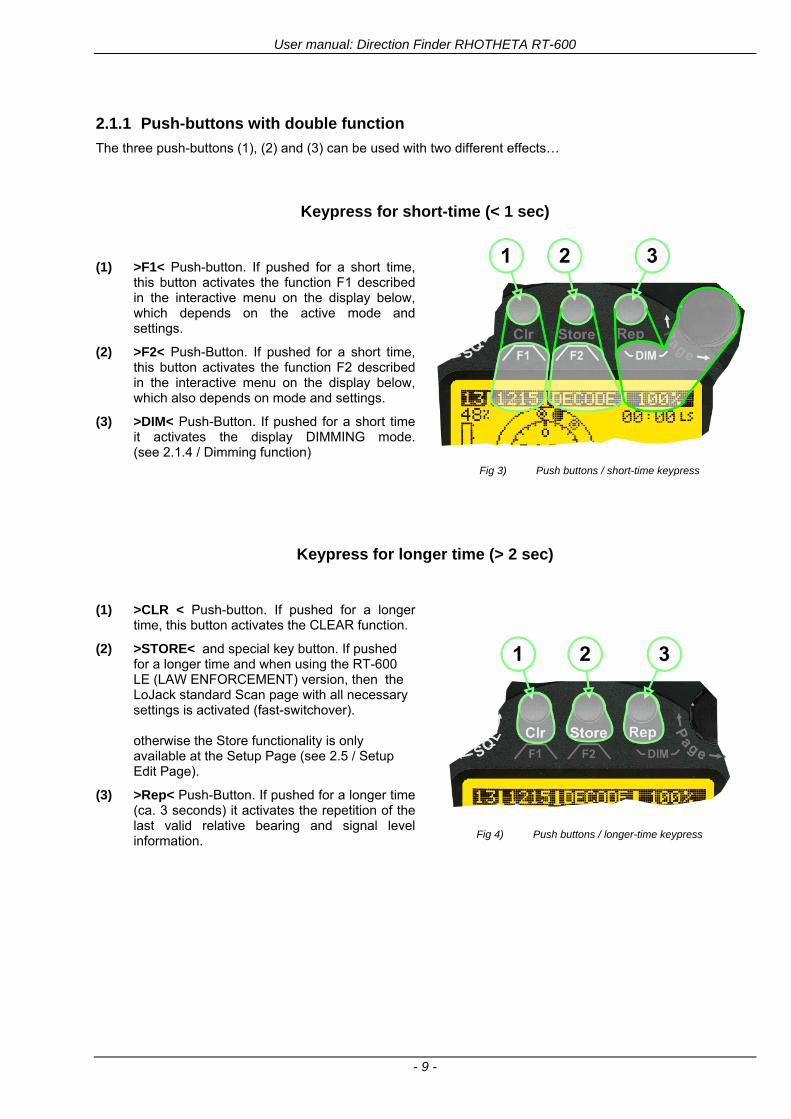
User manual Direction Finder RHOTHETA RT-600
- 9 -
211 Push-buttons with double function
The three push-buttons (1) (2) and (3) can be used with two different effectshellip
Keypress for short-time (lt 1 sec)
(1) gtF1lt Push-button If pushed for a short time
this button activates the function F1 described in the interactive menu on the display below which depends on the active mode and settings
(2) gtF2lt Push-Button If pushed for a short time this button activates the function F2 described in the interactive menu on the display below which also depends on mode and settings
(3) gtDIMlt Push-Button If pushed for a short time it activates the display DIMMING mode(see 214 Dimming function)
Fig 3) Push buttons short-time keypress
Keypress for longer time (gt 2 sec)
(1) gtCLR lt Push-button If pushed for a longer
time this button activates the CLEAR function
(2) gtSTORElt and special key button If pushed for a longer time and when using the RT-600 LE (LAW ENFORCEMENT) version then the LoJack standard Scan page with all necessary settings is activated (fast-switchover) otherwise the Store functionality is only available at the Setup Page (see 25 Setup Edit Page)
(3) gtReplt Push-Button If pushed for a longer time (ca 3 seconds) it activates the repetition of the last valid relative bearing and signal level information
Fig 4) Push buttons longer-time keypress
User manual Direction Finder RHOTHETA RT-600
- 10 -
212 Power-On procedure
After switching on the DCU pressing the ONOFF pushbutton a startup screen is displayed for five seconds
Fig 5) Power-On Screen
(1) System Type RT-600
(2) System Version ldquo(L)rdquo for LAW ENFORCEMENT version or ldquo(A)rdquo for STANDARD version
(3) Web Address (URL)
(4) Software Revision of AU (antenna unit)
(5) Serial Number of AU
(6) Additional service and maintenance information (the two characters indicate installed options)
(7) Software Revision of DCU (display control unit)
(8) Serial Number of DCU
After five seconds the equipment switches to the operational mode (for LAW ENFORCEMENT version the LoJack Scan page is displayed as home page by default)
User manual Direction Finder RHOTHETA RT-600
- 11 -
213 Main Pages Selection
Two main modes can be selected from the DCU front panel
DF Mode Page displays all relevant operational bearing information depending on the type of signal being received
FREQ SELECTION Page allows to access and edit all pre-programmed frequency memory channels
Fig 6) Page Selection
(1) The gtPagelt rotary switch is used to select the active page
(2) The active page is highlighted with dark background
(3) The inactive page which may be selected is displayed in dark letters on bright background
214 Dimming function
The background of the LC-graphic display is equipped with an LED array and its brightness may be adjusted continuously from 5 to 100 Dimming follows an exponential curve resulting in very accurate adjustment under night conditions
Fig 7) Dimming Adjustment
(1) Pressing the gtRepDIMlt button for a short time activates the
DIMMING mode
(2) Brightness actual information in percentage from 5 to 100 in 5 steps is displayed instead of the ldquoPagerdquo field in the upper right corner of the display
(3) The gtPagelt knob is used to adjust the brightness in 5 steps left and right
The active brightness level of the display will remain stored after switching off the unit separately for day and nightNVG mode
After ca 3 sec of inactivity the display will fall back to the prior main page Dimming of legends can be adjusted in two ways
Internal dimming of legends
Internal dimming is always active If an external dimming voltage is not used or is lt 1V DC legends are dimmed in the same manner as the LC display
External (remote) dimming of legends
If the external dimming voltage is gt 1V DC the brightness of the legends is controlled by the external dimming voltage (Refer to the wiring plan and to the operatingsetup-menu description)
User manual Direction Finder RHOTHETA RT-600
- 12 -
215 Squelch Operation
The main challenge of operating a direction finder is trying to use only the signal transmitted by the target in order to calculate its bearing accurately because noise and RF disturbances will cause misleading bearing indications In order to prevent the direction finder to calculate bearing results which are due to noise and disturbances several techniques are available If a signal can be distinguished from noise or other signals by its message content (eg LoJack ID) only transmissions containing the required message content are used for bearing In other cases the squelch can be used to suppress unwanted weak signals and noise A squelch level called threshold has to be set by the user or automatically by the system All signals with strength below this threshold value will be ignored while signals with strength above this level will cause a bearing indication So for a signal to be usable for bearing calculation it has to be sufficiently stronger than noise or disturbing signals that the receiver can clearly distinguish between wanted and unwanted signals As a result of the squelch technique the receiver sensitivity is reduced to the level set by the squelch threshold decreasing the maximum distance or range to the transmitter However it might be desirable to obtain bearing information even for weak signals which are very close to the noise level In this case it will be necessary to reduce the squelch level below the noise level As soon as the modulation of a signal can be heard on the speaker it can be expected that bearing calculation is possible If the noise is randomly distributed ndash as with ldquowhite noiserdquo ndash and no other signal is received the bearing indication will also be random If the noise is not random but rather a specific disturbance the bearing indication will point to the source of the noise If there is a very weak signal ldquoburiedrdquo in the noise this signal will produce a correct bearing indication thanks to sophisticated bearing technologies used in the RT-600 system Fluctuations due to noise will be small even at low signal levels however the reaction time of the bearing indication can increase To verify if a bearing indication is due to white noise or to an internal disturbance source or if it is due to a valid signal the aircraft should make a slow turn If the bearing indication is due to an external signal eg a SAR beacon the bearing indication should compensate the changed relative flight angle Example with a bearing indication of 30deg The signal is hardly audible as it is buried in the noise The airplane makes a turn left by 60deg If the bearing indication is not changing to approximately 30deg+60deg = 90deg after a few seconds the bearing is likely to be due to noise or internal disturbances from the aircraft Note The weaker a signal is the longer it will take to change the bearing Durations around 5 seconds are not unfamiliar in such cases Therefore it is not useful to use this procedure for signals with short transmission times and low transmit duty cycles such as COSPAS-SARSAT transmission The procedure is best suited for ELT transmission with a continuous signal and still well-suited for ELTs with intermittent transmission (down to 33) In cases where pulsed signals are to be received the receiver is able to decide automatically which squelch level is best-suited for normal operation In such cases an automatic (ldquoArdquo) squelch is provided The threshold is automatically set to a value higher than the calculated noise level The difference in dB between noise and threshold level can be defined in the Setup Menu Refer to the chapter ldquoSetup Pagerdquo for details During AUTO squelch operation the user has the possibility to force the squelch into MANUAL mode but needs to be aware of the operational limitations described in this chapter In cases where the Antenna Unit checks signal validity autonomously and without useful possibilities of user interaction user interaction is not possible and the squelch purely follows internal rules appropriate to the type of signal received
User manual Direction Finder RHOTHETA RT-600
- 13 -
Examples of different squelch settings
Fig 8) Manual squelch mode correct squelch
adjustment
Correct squelch adjustment If the squelch is set to level (b) slightly over the noise level (a) the receiver audio output remains quiet and no wrong noisy bearing is indicated
Fig 9) Manual squelch mode Incorrect squelch
adjustment
Incorrect squelch adjustment If the squelch level is set (b) below the noise level (a) a wrong noisy bearing is indicated
Fig 10) Automatic squelch mode
Automatic squelch mode Automatic squelch mode is indicated by an ldquoArdquo (c) above the squelch level marker Depending on the SN-Ratio setting the squelch level is automatically set slightly higher than the noise level Using the SQL rotary switch (1) the user can change to manual squelch mode Automatic squelch mode can be activated again by setting the squelch level manually to lt 0 or gt 60
Fig 11) Automatic squelch mode with strong signal
Automatic squelch mode with strong signals Strong short receive signals will not modify the squelch level setting
Fig 12) Automatic squelch mode and not adjustable by
the user
Automatic squelch mode level not re-adjustable by user When the squelch is adjusted automatically by the system and the user is not allowed to change it an ldquoXrdquo (c) is displayed above the squelch level marker
User manual Direction Finder RHOTHETA RT-600
- 14 -
22 Frequency (FRQ) Selection Page The Frequency Selection (FRQ Selection) Page allows the user to select a frequency select a band and edit a frequency
Open FRQ Page
From the ldquoDFrdquo standard page activate the Page Rotary Switch in any direction to open the ldquoFRQrdquo Page for Frequency Selection
Fig 13) Open FRQ Page
Fig 14) FRQ ndash Frequency Selection Page
221 Selecting a Frequency
(1) Use the Page knob ldquoFRQrdquo again to select (recall) a frequency from
gtMEMlt four (4) memory channels gtWlt one (1) working (operating) frequency gtFIXlt fixed frequencies gtCPSARlt seven (7) COSPAS-SARSAT channel groups
(2) The actual adjusted frequency
(3) Frequency band-information
Exit Frequency dialogue
(4) Press push-button gtF1lt ldquoEXITrdquo to exit to DF mode (using the actual frequency
222 Recalling and editing frequencies from a memory channel
Recall
(1) With changing the Page rotary knob memory channels 1 4 can be selected The gtmarkerlt symbol indicates the actual memory channel
Edit
(2) MHz plusmn edits the MHz Value of the actual frequency
(3) kHz plusmn edits the kHz Value of the actual frequency
(4) F2 switches to next band
gtMHzlt and gtkHzlt directly changes and overwrites the actual selected memory frequency inside the actual band (see also 224 Editing a Frequency)
Fig 15) Recall frequency of Memory channel 3
User manual Direction Finder RHOTHETA RT-600
- 15 -
223 Recalling frequencies from fixed frequencies or CospasSarsat Channels
Fig 16) FRQ Selection Page with FIX1 selected
(1) ldquoFIXrdquo Selection range for fixed frequencies
for RT-600 Standard version for RT-600 Law Enforcement version
FIX1 ldquoEltPlbrdquo 121500 MHz international VHF air distress emergency frequency
FIX2 ldquoChnl16rdquo 156800 MHz marine VHF emergency radio channel 16
FIX3 ldquoEltMILrdquo 243000 MHz military UHF air distress emergency frequency
FIX1 ldquoEltPlbrdquo 121500 MHz international VHF air distress emergency frequency
FIX2 ldquoChnl16rdquo 156800 MHz marine VHF emergency radio channel 16
FIX3 ldquoLE(USA)rdquo 173xxx MHz LoJack Recovery System
FIX4 ldquoETSSTDrdquo 216487 MHz ETS standard frequency
FIX5 ldquoETSUCVrdquo 216512 MHz ETS ucover frequency
(2) ldquoCPSARrdquo Selection range for Cospas Sarsat channel groups
CPSAR1 ldquo022-028rdquo 406022 hellip 028 MHz Channel A B C
CPSAR2 ldquo031-037rdquo 406031 hellip 037 MHz Channel D E F
CPSAR3 ldquo040-043rdquo 406040 hellip 043 MHz Channel G H
CPSAR4 ldquo046-052rdquo 406046 hellip 052 MHz Channel I J K
CPSAR5 ldquo055-061rdquo 406055 hellip 061 MHz Channel L M N
CPSAR6 ldquo064-070rdquo 406064 hellip 070 MHz Channel O P Q
CPSAR7 ldquo073-076rdquo 406073 hellip 076 MHz Channel R S
User manual Direction Finder RHOTHETA RT-600
- 16 -
224 Editing a Frequency
While on the FRQ SELECTION Page the user can directly edit the frequency displayed
Fig 17) FRQ Selection Page before frequency editing
(1) gtMHzlt Rotary switch for direct adjustment of the displayed MHz range inside the actual band
(1 x step = 1 MHz adjustment)
(2) gtkHzlt Rotary switch for changing the displayed kHz frequency according to the actual band frequency grid (as example 8333 kHz at the VHF airband)
(3) gtF2lt Adjustment of the next available band (see next page gtgt Selecting a Frequency Band)
Fig 18) FRQ Selection Page after frequency editing
If the selected and marked frequency is not one of the MEM [14] channels then the changed frequency is automatically stored in the work frequency WorkFRQ channel
User manual Direction Finder RHOTHETA RT-600
- 17 -
225 Selecting a Frequency Band
While on the FRQ Selection Page each available band can be selected by pressing F2 BAND
(1) Press push button F2 BAND for
switch over to the next band
(2) Designation of actual selected band
(3) Max frequency limits of the actual selected band (depends on wide band options)
Fig 19) FRQ Selection Page (bands)
Frequency bands availability depends on the system version (A LE) and its wide band options (F1 to F4) These optional wide bands are available if ordered in addition to the default bands Here is a listing of DEFAULT and OPTIONAL bands available with each version of the system RT-600 (STANDARD) Listing of bands
Default bands available OPTIONAL extended bands available
Band designation Frequency limits Option Designation Frequency limits
VHF Emergency Band 118000 hellip 124000 MHz gt F1 VHF Air Band 118000 hellip 136992 MHz
VHF Marine Band 154000 hellip 163000 MHz gt F2 Extended VHF Marine 137000 hellip 224995 MHz
UHF Emergency Band 240000 hellip 246000 MHz gt F3 UHF Air Band 225000 hellip 399975 MHz
COSPAS SARSAT 400000 hellip 406092 MHz
UHF FM Band 406100 hellip 410000 MHz gt F4 Additional UHF FM 406100 hellip 470000 MHz
RT-600 (Law Enforcement) Listing of bands
Default bands available OPTIONAL extended bands available
Band designation Frequency limits Option Designation Frequency limits
VHF Emergency Band 118000 hellip 124000 MHz gt F1 VHF Air Band 118000 hellip 136992 MHz
VHF Marine Band 154000 hellip 163000 MHz gt F2 Extended VHF Marine 137000 hellip 163000 MHz
LoJack 164000 hellip 174000 MHz
ETS 216000 hellip 220000 MHz
COSPAS SARSAT 400000 hellip 406092 MHz
User manual Direction Finder RHOTHETA RT-600
- 18 -
23 Direction Finder (DF) Mode Direction Finder (DF) mode is generally used to display all valid information processed by the DF from the signal received from a target transmitter The amount and kind of information displayed by the DCU depends on the type and content of the signal received and processed by the DF Simple signals such as the analog sweep-tone modulation received from a SAR beacon (ELT PLB EPIRB PDD) on 121500 MHz allow displaying only basic bearing information while digital signals such as COSPAS-SARSAT and LOJACK allow displaying more information for ex beacon IDs GPS coordinates codes VLUs etc
231 Operating Elements in DF Mode
Fig 20) Operational Elements in DF Mode
This picture shows the DCU operating in DF Mode on the international emergency frequency 121500 MHz
with an active signal being received (1) gtFREQUENCYlt Rotary switch activates the ldquoFRQrdquo frequency page for changing and selecting the
active frequency The last selected frequency remains stored after switching offon the device The selected frequency is shown on the graphic display bottom right Above additional information for the selected frequency is displayed The use of the rotary switch activates a sub-page Please refer to the Frequency Selection section for details
(2) gtVOLUMElt Rotary switch to adjust the audio output level The volume of a linked external speaker or amplifier can be adjusted in a range from 0 (off) to 99 (maximum loudness) The selected volume is shown in the bottom left corner of the graphic display The volume remains stored after switching offon the device
(3) gtSquelch Levellt adjusts the squelch level The squelch level has to be above the receiving level without signal (noise) Only signals above the squelch level are audible in the loudspeaker and used by the direction finder for bearing indication The gtSQLlt rotary switch allows to select the squelch threshold ie a minimum signal strength of an incoming signal to be processed The current settings on a signal level scale from 0 to 60 is shown in bright letters on dark background below the SQL rotary switch and as an arrow beside the signal Strength Bar-Graph
(4) The gtCLRlt Push-button is used for erasing the internal bearing value averaging store and the Last Signal Timer To activate this function the push-button has to be hold down for a minimum of circa two seconds The sophisticated averaging store increases bearing precision and enables at all an usable
User manual Direction Finder RHOTHETA RT-600
- 19 -
bearing display in case of bad receiving signals (if there is a far away transmitter andor temporary complete loss of a receiving signal) Caused by the averaging procedure a drag error may occur which might be disturbing the bearing indication after a quick change of course of the aircraft or vehicle In this case the indicated bearing value lags by the real bearing value for about two seconds (for very weak signals even longer) By pressing this push-button after a quick change of course the display will show the new bearing value without drag error Additionally the F1CLR Push-Button is used to activate specific functions high-lighted in the menu below the button by pushing it for a short time (here as example ldquoSCANrdquo starts scanning the actual air band)
(5) gtSTORElt push-button Without function except if a special function is high-lighted in the menu line of the display
(6) gtREPEATlt Push-button when pressed and hold for min 3 sec the last valid bearing value with corresponding receiving level is displayed
232 Standard Display in DF Mode
Fig 21) DF Mode
(1) gtRelative Bearing valuelt by means of a sophisticated averaging procedure a steady display is
accomplished as graphic display and as text in the range of 0deghellip 359deg (0deg corresponds to bearing direct ahead)
(2) gtSpreadlt maximum deviation of un-averaged bearing values This is an indicator of bearing quality The wider the range between the directions of maximum deviation the worse the received signal is As a result of the excellent averaging procedure even with a spread of 45deg good bearing results are achieved
(3) gtReceiving levellt (field strength) of the signal as a relative percentage value visualized as bar-graph indication and as decimal value Even without a received signal a certain noise level may be displayed
(4) gtSquelch levellt (independently adjustable and stored for each frequency band) Squelch level is indicated as marker at the Signal Strength Bar-Graph or as direct relative level value A usable bearing analysis can only be achieved if the squelch level is above the noise level (without received signal) If the antenna unit is placed close a heavily disturbing electronic devices the squelch level has to be raised thus making the direction finder being less sensitive In receive modes where the squelch level is set automatically an ldquoArdquo above the marker indicates the ldquoAutosquelchrdquo functionality
(5) gtLast Signallt timer showing the time since a signal has been received for the last time (ie since a signal has been stronger than the squelch level) Values are ldquominutes secondsrdquo
User manual Direction Finder RHOTHETA RT-600
- 20 -
233 Special Options in COSPAS-SARSAT DF Mode
Especially for the use together with beacons transmitting a data signal according to COSPAS-SARSAT specifications in the 406-MHz-Band special functionalities and pages are being provided After selection of a COSPASSARSAT Frequency (Refer to the chapter ldquoFrequency selection Pagerdquo) the bearing page provides additional information and operating options
Fig 22) Operational Elements and Display in COSPAS-SARSAT DF Mode
(1) gtAuto Squelchlt indication indicating that the squelch level is set automatically to be close to the noise
floor It is recommended to always use the Auto Squelch during COSPAS-SARSAT operation This can be achieved by manually selecting 0 (lowest possible value) or 60 (highest possible value) as squelch level During COSPAS-SARSAT-Operation this will force the automatic setting of the level
(2) gt121500lt menu option The COSPAS-SARSAT signal in the 406 MHz band is transmitted only every 50 seconds in form of a short data burst of 440 or 520 ms approaching the transmitter it will be received earlier than the 121500 MHz continuous signal due to its high transmitter power However in a lower distance to a transmitter bearing on 121500 MHz is faster thanks to the continuous or rapidly intermittent signal The 121500 MHz menu option allows a direct switch-over to 121500 MHz Direct return back from 121500 to the COSPAS-SARSAT band is possible from the 121500 MHz bearing Window in COSPAS-SARSAT mode Please refer to the chapter ldquo121500 MHz bearing Window in COSPAS-SARSAT moderdquo for details
(3) gtDecodelt menu option allows to open the COSPASSARSAT Decode sub-page by shortly pushing the F2 push-button above the menu option
(4) gtFrequency rangelt indication COSPAS-SARSAT is using a channel spacing of 3 kHz for its beacons Due to the internal architecture of the direction finder it is possible to receive more than one channel in the same time Thus frequency steps of the direction finder are 833 kHz instead of 3 kHz The receive frequency covered by the current receive frequency setting is shown in the display line above the receive frequency indication
Important If the exact frequency of the COSPAS-SARSAT beacon is unknown it is strongly recommended to use the COSPAS-SARSAT scanning functionality in order to detect the correct frequency (Refer to the chapter ldquoFrequency selection Pagerdquo amp ldquoCOSPAS-SARSAT Scan Moderdquo)
User manual Direction Finder RHOTHETA RT-600
- 21 -
234 COSPAS-SARSAT Decode Window
The COSPAS-SARSAT Decode Window allows decoding incoming COSPAS-SARSAT data messages Only while this decode window is activated the decoding is possible An already received COSPAS-SARSAT puls while DF bearing mode was activated can not be used for decoding afterwards In this case the user has to wait while this decode window is active for the next transmitted puls approx 50 sec later
Fig 23) COSPAS-SARSAT Beacon Information Page
(1) gtExitlt push button (F1 button) allows to exit the decode window and switch back to the COSPAS-
SARSAT DF Mode page
(2) gtSARSATlt in the upper right corner of the display indicates that the COSPAS-SARSAT decode function is activated
(3) gtCountrylt displays the COSPAS-SARSAT Country Code coded into the received data message
(4) gtLast Signallt time since the last COSPAS-SARSAT message has been received in minutes secondsrsquo format
(5) gtPositionlt field showing in case of location protocols being used by the beacon the encoded GNSS position data (latitude longitude) transmitted by the beacon
(6) gt15-HEX-IDlt 15-HEX-ID of the beacon in hexadecimal format
(7) gtData stringlt of the bits 25 to 112 of the COSPAS-SARSAT data burst in case of short messages and bits 25 to 144 in case of a long message format The last 8 Hex Values are separated by a blank Bit- and Frame-synchronization hex values (Bits 1 to 24) are suppressed to increase the readability of the data message
(8) gtXlt sign to indicate that the Squelch is controlled by the antenna unit for optimum sensitivity The user has no access to the Squelch setting
User manual Direction Finder RHOTHETA RT-600
- 22 -
235 Tracking 121500 MHz while in COSPAS-SARSAT Mode
While in COSPAS-SARSAT DF Mode the user can switch to 121500 MHz in order to track the beacon in VHF If a valid signal is not received in 121500 MHz the user can switch back to the last active COSPAS-SARSAT channel (406 MHz frequency) being tracking previously
Fig 24) Tracking 121500 MHz while in COSPAS-SARSAT Mode
Differences are (1) gt406xlt press F1 to switch back to the last
COSPAS-SARSAT channel (406 MHz frequency) being tracking previously
(2) gt121500 MHzlt Actual frequency being tracked
User manual Direction Finder RHOTHETA RT-600
- 23 -
236 COSPAS-SARSAT Scan Mode
If the COSPAS-SARSAT Scan Mode has been selected at the frequency selection page ldquoFRQrdquo the COSPAS-SARSAT channels as selectable manually from the Frequency Selection Page are scanned After reception of a COSPAS-SARSAT Signal the scanning is stopped at the received frequency Due to the fast scanning ndash the complete COSPAS-SARSAT sub-band is scanned within less than 400 ms ndash detection of a receivable COSPAS-SARSAT signal is possible within one COSPAS-SARSAT repetition cycle
Fig 25) FRQ Selection Page with SCN COSPAS-SARSAT Scan Page selected
At the frequency selection page an active COSPAS SARSAT scanning can be stopped by de-activating it with the rotary button (1) While the scanning is active it is also possible by pressing gtF1lt ldquoEXITrdquo to switch back to the DF pagehellip
Fig 26) DF page with active COSPAS-SARSAT Scan Mode at the DF page
(1) gtSCANlt flashing indication notifying the user that the equipment is operating in scan mode
(2) Frequency display indicating the COSPAS-SARSAT scanning frequency range
(3) gtXlt sign showing that squelch settings are controlled autonomously by the receiver
Scan mode can be left by pressing gtF1lt ldquoSTOPrdquo
User manual Direction Finder RHOTHETA RT-600
- 24 -
237 Marine Ship Scan Mode
Fig 27) DF Mode FRQ = 156800 MHz F1 for scan function
If the active frequency (2) is within the VHF Marine Band a fast scan of all ship channels is possible by pushing gtF1lt ldquoSCAN (1) In this scanning mode all marine channels 1 to 88 (156025 to 157450 MHz) are scanned continuously until a signal is received To offer the best monitoring functionality for the user also signals between to channels (4) are detected (scanning without gap) In order to prevent the scan to stop on noisy frequencies it is recommended to start scanning with high squelch settings You can reduce the squelch level in steps until the scan stops on a noisy frequency for the first time Then increase the squelch level slightly This will result in the highest possible scan sensitivity and avoiding noisy channels due to RF disturbances sometimes generated by other equipment in own aircraft
Fig 28) DF Mode active scanning in process
The scanning is stopped by pressing gtF1lt ldquoSTOPrdquo (3)
User manual Direction Finder RHOTHETA RT-600
- 25 -
24 Law Enforcement Operation Law enforcement special ops and other organizations use the RT-600 LE (LAW ENFORCEMENT) version instead of the RT-600 A (STANDARD) version One of the reasons is that the LE version features scanning and tracking of signals like LoJack and ETS as well as signals in the 216000 MHz ndash 220000 MHz band such as medical beacons wristankle transmitters cashasset recovery ldquotagsrdquo etc However the LE version shares many functions in common with the A version such as scanning and tracking in the AIR band COSPAS-SARSAT band etc
241 Power-On procedure
The power-on procedure is the same as described in 211
(1) System Version ldquo(L)rdquo for LAW ENFORCEMENT version
Fig 29) STARTUP Screen (see 211 for details)
242 LoJack Scan Mode Start scanning for a VLU Code
For the convenience of Law Enforcement and other special ops users who frequently engage in tracking SVRS (Stolen Vehicle Recovery System) signals such as LoJack (LoJack Corp FCC 9020 Part 2 SVRS) RHOTHETA has optimized the power-on procedure of the RT-600 LE version so that right after the STARTUP screen the unit displays automatically the LoJack Scan Mode page to start immediately scanning for a valid VLU (Vehicle Location Unit) code without pressing any key
Fig 30) LoJack Scan Mode unit is scanning for a LoJack VLU Code
(1) gtscan LoJacklt DF is scanning for any new LoJack VLU Code
(2) gtEXITlt press F1 to exit and switch directly to DF Mode
User manual Direction Finder RHOTHETA RT-600
- 26 -
243 LoJack Scan Mode from any other page
While operating on any page other than the LoJack Scan page the user can switch directly to LoJack Scan Mode by pressing Hotkey F2 for 2 secs
(1) press Hotkey F2 for 2 secs to switch to the LoJack Scan page
Fig 31) Hotkey F2
User manual Direction Finder RHOTHETA RT-600
- 27 -
244 Manual activation of LoJack Scan Mode
(1) select the LoJack frequency (see also Frequency Selection Page)
(2) press F1 to switch back to the DF MODE
Fig 32) FRQ Selection Page FRQ = LoJack BAND = LoJack (164-174 MHz)
While in DF MODE with adjusted LoJack frequency the user can switch directly to the LoJack Scan by pressing gtF1lt ldquoSCANrdquo
(1) press F1 SCAN to switch to the LoJack Scan page
(2) still no LoJack ID filter used (ID=off) all transmissions are received on the active frequency as example also unwanted tower pulses
Fig 33) DF Mode with LoJack filter OFF
User manual Direction Finder RHOTHETA RT-600
- 28 -
245 Receiving and accepting a new VLU Code
While in LoJack Scan Mode waiting for a VLU Code if a new VLU Code is displayed the user can accept it and switch directly to DF Mode by pressing F2
(1) a new LoJack VLU Code (0001A) has been received
(2) press F2 to accept the new VLU Code (0001A) and switch to DF MODE page with the LoJack filter activated to track only 0001A
Fig 34) LoJack Scan Mode with new VLU Code received
246 Entering a new VLU Code manually
While in LoJack Scan Mode the user can enter a LoJack VLU code also manually
(1 2 3) use the SELECTplusmn and plusmnVALUE knobs to enter a new LoJack VLU Code active ID (0001A)
(4) Press F1 to accept the new VLU Code and switch to DF Mode with the LoJack filter ON to track only 0001A
Fig 35) LoJack Scan Mode with new VLU Code entered manually
User manual Direction Finder RHOTHETA RT-600
- 29 -
247 Tracking one VLU Code while monitoring new VLU Codes
While on DF Mode and tracking a VLU Code (0001A) the user can turn the LoJack switch OFF with F2 also the user can start scanning all VLUs again with F1
0001A is displayed as the active VLU Code filter function is ON only 0001A is tracked
Monitoring of other VLU Codes is active in the background
(1) Press F1 to switch to the LoJack Scan Mode to scan for new VLU Codes
(2) Press F2 to switch LoJack filter OFF
Fig 36) DF Mode with active VLU Code and LoJack filter ON
248 Tracking one VLU Code and receiving a new VLU Code
While on DF MODE page and tracking VLU Code (0001A) in the background a new VLU Code is received and decoded (G2HC7)
(1) The new VLU Code is announced (NEW G2HC7)
(2) Press F1 to switch to LoJack Scan Mode to see the arrival time of G2HC7 and the possibility to change bearing to this new G2HC7
Fig 37) DF Mode with active VLU Code and announcement of new VLU Code
User manual Direction Finder RHOTHETA RT-600
- 30 -
249 Switching to a new VLU Code
While on the LoJack Scan Page tracking one VLU Code (0001A) and notified of a new VLU Code (G2HC7)
(1) press F1 to continue tracking 0001A
(2) press F2 to start tracking G2HC7
(3) Time elapsed since G2HC7 was last received
(4) Time elapsed since 0001A was last received
If F1 is pressed for 2 sec the indicated VLU Code (G2HC7) and ID (0001A) are deleted
Fig 38) LoJack Scan Page with one active VLU Code and one new VLU Code
2410 ldquoBlockingrdquo function of one LoJack VLU Code
The LoJack scan page can also be used to ldquoblockrdquo one unwanted LoJack VLU ID signal by separating the adjusted active ID from any other received LoJack VLU signal This is done by muting the audio (see example below) when a LoJack signal with VLU code ldquo0001Ardquo is received gtgt Any new VLU Code (active LoJack signal) - except for 0001A ndash will be displayed on the top row and generate the audible beep tone
Fig 39) LoJack Scan Page with one active VLU Code and audio OFF
Tip ldquoBlockingrdquo is an important tool for practical missions As example a stolen vehicle with VLU ID ldquo0001Ardquo was tracked in the DF bearing mode The mission
is completed but the VLU is normally still transmitting With the settings above only new VLU signals except the now unwanted ldquo0001Ardquo are audible and displayed in the upper (scan LoJack hellip for new VLU) box
User manual Direction Finder RHOTHETA RT-600
- 31 -
2411 Tracking in the 216 to 220 MHz band
The RT-600 features scanning and bearing functionality in the 216000 MHz to 220000 MHz band The 216000 MHz ndash 220000 MHz band contains frequencies and signals used by special services and tracked by law enforcement special ops and similar organizations These are some of the frequencies and services in this band
CFR 90259 tx 216000 MHz to 220000 MHz
Low Power Radio Service (LPRS) tx 216000 MHz to 217000 MHz
Medical beacons Project Lifesaver tx wristankle tx 213000 MHz to 216000 MHz
ETS tx stolen cashasset recovery tx ldquobaitrdquordquotagrdquo tx 216000 MHz to 220000 MHz tx = transmitter(s) However any future or current user of the Rhotheta RT-600 must be aware that tracking signals on the frequencies listed above may be challenging and even frustrating due mostly to negative factors in some of the transmitters
bull Very low RF power output
bull Inefficient antennas
bull Battery-powered devices with a ldquolow batteryrdquo condition
bull Devices worn or located in conditions of poor RF propagation
bull Devices with channel spacing different than the one specified for the RT-600
These factors can make it very difficult for the DF to receive the signal andor display an accurate bearing Disclaimer For the reasons explained above and even though the RT-600 features top performance in its class RHOTHETA does not offer - and is not to be held responsible for - any guaranteed minimum range or distance to a transmitter in this band
25 Setup Edit Page System settings are displayed in the setup page The functions described in this section should be used by trained personal only
Fig 40) Accessing the Setup Page
The setup page can be accessed by holding down the gtCLRlt (1) and gtREPlt (2) buttons simultaneously and in the same time performing a left-hand turn on the gtPagelt rotary switch (3)
User manual Direction Finder RHOTHETA RT-600
- 32 -
Fig 41) Setup Page
(1) gtStorelt push-button must be pressed in parallel if a value of a setting shall be modified If a value can
be modified the background stops to blink
(2) gtSelectlt rotary switch used to scroll through the menu options The value of the actually activated menu option is high-lighted with dark background and blinking
(3) gtValuelt rotary switch used to change values in menu options (gtStorelt (1) has to be pressed in parallel if a value shall be modified)
(4) gtSN-Ratiolt menu option representing the necessary Signal-To-Noise-Ratio (Difference between signal and noise level) used as criterion for the automatic squelch function Please refer to the chapter ldquoSquelch Operationrdquo for details Default value is 60 dB
(5) gtMounting Positionlt menu option to select Top- or Bottom-Mounting of the DF antenna In case of rooftop installation (eg on land vehicles) ldquoToprdquo shall be selected In case of bottom-down (upside-down) installation (eg on a helicopter) ldquoBotrdquo shall be selected If this option is not selected correctly all bearing values will be mirror-inverted
(6) gtBearing Offsetlt menu option to include a constant offset correction to the bearing indication Bearing values in degrees will be changed according to the offset value
(7) gtMaximum External Dimming Voltage for Legendslt menu option which sets the upper limit of the dimming input voltage for the legends-panel Range=[15 hellip 28]V
(8) gtMinimum External Dimming Voltage for Legendslt menu option which sets the lower limit of the dimming input voltage for the legends-panel Range=[15 hellip 28]V
(9) gtPagelt rotary switch to be turned right-hand to go back to the Direction Finder page A left-hand turn on this rotary switch will show up an additional service page with debug information used for system checks
(10) gtExtended Seriallt It is possible to enable or disable the extended serial data protocol Only of interest if serial data is used by any connected control units like moving maps or computers For detailed information see (Serial interface data protocol (short description)gt at page 46) If there are compatibility problems with already existing older remote control software it is recommended to switch OFF the extended serial data protocol
User manual Direction Finder RHOTHETA RT-600
- 33 -
3 Error messages If an internal error of the device is recognized a corresponding flashing error message will be shown in the DF pages
Fig 42) Error Messages
(1) Error message including error code (in brackets)
(2) Short description of the indicated error
In case of coincidence of various errors the error with the highest priority will be displayed
Error message Error location Reason
Error (12) VOLTDU
Main voltage supply Main Voltage input too low ( 100 V)
Error (11) NO AU
Connection antenna display or Antenna Unit
No serial data (RS485) from Antenna Unit No or damaged connection between antenna and display or damaged antenna unit
Error (10) BAD AU
Connection antenna display
Incompatibility or bad data connection between display and antenna
Error (9) BAD RU
Remote Unit Incompatibility or bad data connection between display and external serial Remote Unit or PC
Error (8) VOLTAU
Antenna Unit Voltage supply at Antenna Unit too low ( 90 V) Main voltage supply too low or considerable drop of voltage between display and antenna
Error (7) BAD DCU
Connection Display Antenna
Incompatibility or bad data connection between antenna and display
Error (6) NO DCU
Connection Display Antenna
No serial data from Display Control Unit to Antenna Unit
Error (5) PLL ERR
antenna Error in synthesizer-oscillator of receiver in Antenna Unit
Error (4) FRQ+OFS
received transmitter Received frequency too high (more than 6 KHz error of transmitter)
Error (3) FRQ-OFS
received transmitter received frequency too low (more than 6 KHZ error of transmitter)
Error (2) DECODE
radio distance transmitter DF
Data Bits of decoded signal (COSPAS-SARSAT or LoJack) defective
Error (1) DATARNG
Incompatibility of data DCU AU
Protocol data bytes out of valid range
Error (0) NO REC
Antenna Unit receiver
Receiver board defective
User manual Direction Finder RHOTHETA RT-600
- 34 -
4 Installation
41 Antenna unit A convenient position of the monopole bearing antenna is crucial for good bearing results The antenna needs an effective ground connection to the body of the aircraft or to the roof of the vehicle If there is no metallic mounting surface available a metallic sheet or similar (net) with connection to ground has to be applied first between vehicle-body and antenna In this hatched area the antenna touches the body ofthe vehicleaircraft In order to obtain a good groundconnection the surface of the body should be bared(Measuring unit [mm])
8 x holes for mounting the antenna unit to the
vehicle aircraft
Fig 43) Antenna Mounting Drawing
User manual Direction Finder RHOTHETA RT-600
- 35 -
411 Influence of antenna location and environment on the bearing accuracy
Recommendations concerning the practical antenna unit location on helicopters and airplanes
The bearing accuracy of the direction finder antenna unit is severely influenced (comparable to an airspeed sensor) by the environment For comparison a perfect high quality speed sensor will not indicate the true airspeed if this sensor is interfered by strong turbulences The direction finder antenna unit acts as a sensor for electromagnetic waves In the near field of this antenna unit any conductive (eg metallic) obstacle will influence the incoming wave field and create reflections which decrease the bearing accuracy These are general physical limitations concerning all types of direction finder systems To achieve the best bearing results it should be considered that the antenna unit is installed as far away as possible from any other vertically polarized conductive structure If possible there should be no reflectors within an area of 2-3 feet around the antenna unit In this worst case example the direction finder will not work properly
Fig 44) Antenna Installed in a Bad Location
In this example the antenna unit is located too close to the cable cutter of the helicopter This cutter will produce strong reflections especially as the length is equal to Lambda4 within the VHF airband
User manual Direction Finder RHOTHETA RT-600
- 36 -
Examples of properly installed direction finder antenna units
Fig 45) Antenna Installed in Good Locations
User manual Direction Finder RHOTHETA RT-600
- 37 -
42 Display and Control Unit
The display control unit may be mounted into a front panel by the means of this mounting drawing
Fig 46) DCU Mounting Drawing
(all dimensions in [mm]) To install or uninstall the display control unit perform the following steps (1) Remove the cover caps of the four rotary switches
(2) Loose the screws visible below the position of the cover caps
(3) Remove the plastic button from the axis of the four rotary switches
(4) Mount dismount the display control unit
(5) Re-install the plastic buttons on the axis of the four rotary switches
(6) Fix the screws so that the plastic buttons are fixed on the axis
(7) Re-install the cover caps on the four rotary switches
User manual Direction Finder RHOTHETA RT-600
- 38 -
43 System Interconnect Wiring Diagram (Also refer to chapter ldquoTechnical Datardquo for details)
Fig 47) System Interconnect Wiring Diagram
6-pol Amphenol plug femalePTG06SE10-6S(SQ)
max length of cable 20 m 9-pol Sub-D plug (femalemale)
User manual Direction Finder RHOTHETA RT-600
- 39 -
5 Technical Data
51 Electric features
Method of bearing Doppler-principle (3 kHz rotational frequency right left rotation)
Bearing accuracy1 plusmn 5deg RMS
Internal resolution 1deg
Bearing Sensitivity VHF AirEmergency le 25 μVm (typical)
VHF Marine le 25 μVm (typical)
UHF Emergency and ETS le 4 μVm (typical)
COSPAS-SARSAT le 4 μVm (typical)
LoJack Decoding (50 Message Error Rate) and bearing le 5 μVm (typical)
Frequency stability plusmn 20 ppm (Δff = plusmn210-6)
Reception frequencies
SAR version (Standard)
Frequency Options
VHF Emergency Band 118000 to 124000 MHz (833 kHz steps AM)
VHF Marine Band 154000 to 163000 MHz ( 500 kHz steps FM) (channel 16 selectable via channel no)
UHF Emergency Band 240000 to 246000 MHz (2500 kHz steps AM)
UHF FM Band 406100 to 410000 MHz ( 500 kHz steps FM)
COSPAS-SARSAT 400000 to 406092 MHz Including 406022 to 406076 MHz (Channel A S)
F1 VHF Air Band 118000 to 136992 MHz
F2 extended VHF Marine Band 137000 to 224995 MHz
F3 extended UHF Air Band 225000 to 399975 MHz
F4 additional UHF FM Band 406100 to 470000 MHz
Reception frequencies
LAW Enforcement version
Frequency Options
VHF Emergency Band 118000 to 124000 MHz (833 kHz steps AM)
VHF Marine Band 154000 to 163000 MHz (500 kHz steps FM) (channel 16 selectable via channel no)
LoJack 164000 to 174000 MHz (125 kHz steps FM)
ETS 216000 to 220000 MHz (10125 kHz AM)
COSPAS-SARSAT 400000 to 406092 MHz Including 406022 to 406076 MHz (Channel A S)
F1VHF Air Band 118000 to 136992 MHz
F2 extended VHF Marine Band 137000 to 163000 MHz
COSPAS-SARSAT fast scan mode
Full automatic detection of any active COSPAS-SARSAT channel A to S within 400 ms
COSPAS-SARSAT decoding
Reception and decoding of COSPAS-SARSAT data signal (112 or 144 bit) specified according to COSPAS-SARSAT
LoJack decoding Selectable LoJack ID display and selective active filtering
Special scanning modes
complete maritime ship band scanning within 3 s (channel 01 hellip 88 also frequencies between 2 channels are included)
1With undisturbed wave field and sufficient field strength Measuring by changing the angle of incidence with the antenna rotating on a revolving table in order to eliminate environmental influences on the results No modulation
User manual Direction Finder RHOTHETA RT-600
- 40 -
Bearable modulation A3E F3E A3X (ELT-modulation) F1D G2D COSPAS-SARSAT Bearing largely independent of modulation
Polarization Vertical
Polarization error 5deg at 60deg field vector rotation
Garbling cone Ca 30deg to the vertical
Time of response2 50 ms (with sufficient reception field strength)
LC-graphic display 128 x 64 pixels supertwist transflective extended range of temperature dark-blue display on yellow-green background background light Freely adjustable (exponential) dimming of brightness
NVG cockpit design Fully compatible NVIS Green B display Control Unit optional
Operating voltage 275 V nominal 12 V to 35 V DC
Current consumption LCD-background light Off max 500 mA (12 V DC) max 250 mA (24 V DC)
LCD-background light 100 max 750 mA (12 V DC) max 350 mA (24 V DC)
LCD-background light 100 max 900 mA (12 V DC) with NVG Option max 400 mA (24 V DC)
Audio out For external speaker approx 2 W (4 Ω)
Serial data interface Serial interface RS-232 (9600 baud 8 data bits 1 stop bit no parity)
2Very weak signals can considerably increase the time of response
User manual Direction Finder RHOTHETA RT-600
- 41 -
52 Interface External connections (optional at Sub-D 9-pol Male connector)
Dimming
Pin 8
external voltage input for variable dimming of legends
(optional)
Analog input signal for variable control of the legends illumination Input voltage range is freely adjustable in the range of 15 hellip 28 V in the setup menu Refer to chapter ldquoSetup Pagerdquo Default setting 8 hellip28 V (8 V = Off 28 V = max dimming for legends)
Input Impedance gt 50 k
Pin 6 night status line for LCD
dimming (optional)
Low-active (as example switch to ground) At input voltage lt 25 VDC the LCD dimming operates in nightNVG mode Maximum brightness ca 4 of daydefault mode brightness
Input Impedance gt 50 k
Pin 4 NVG status line for LCD
dimming (optional)
Low-active (as example switch to ground) At input voltage lt 25 VDC the LCD dimming operates in nightNVG mode Maximum brightness ca 4 of daydefault mode brightness
Input Impedance gt 50 k
AudioLF
Pin 7 Audio output signal
AC coupled voltage source with very low inner resistance Maximum output voltage ca 8 VPP = 283V RMS at maximum Volume Maximum output power ca 2 W with 4 speaker
If a headphone is connected ([32hellip600] 100mW) we recommend using a resistor (18 025 W) between audio output and headphone to prevent damage of the headphone
Serial interface RS232 (9600 baud 8 data bits 1 stop bit no parity)
Pin 3 TXD Serial output (ca plusmn10 V)
Pin 2 RXD Serial input (ca plusmn10 V)
User manual Direction Finder RHOTHETA RT-600
- 42 -
53 Mechanical features
Temperature range
Display Control Unit permissible operating temperature3 -20 degC +60 degC permissible storage temperature -30 degC +80 degC
Antenna Unit permissible operating temperature3 -40 degC +60 degC permissible storage temperature -55 degC +80 degC
Protective system Antenna Unit IP 67
Weights Display Control Unit 250 g Antenna Unit 2000 g
Dimensions Display Control Unit 82 mm x 82 mm x 43 mm (width x height x depth) Antenna Unit 270 mm x 185 mm
Fig 48) DCU Mechanical Drawing (all dimensions in [mm])
3 For temperatures lower than ndash10deg C a warm-up period of 15 min should be allowed
User manual Direction Finder RHOTHETA RT-600
- 43 -
Fig 49) AU Mechanical Drawing (all dimensions in [mm])
User manual Direction Finder RHOTHETA RT-600
- 44 -
6 Appendix
61 Frequency Ranges
User manual Direction Finder RHOTHETA RT-600
- 45 -
62 Frequencies of channels on maritime band (only for standard [A] version) Frequency-range of the RT-600 in the maritime band 156000 MHz 162025 MHz
Channel No frequency (ship - station) Frequency (coast - station)
1 156050 MHz 160650 MHz 2 156100 MHz 160700 MHz 3 156150 MHz 160750 MHz 4 156200 MHz 160800 MHz 5 156250 MHz 160850 MHz 6 156300 MHz 160900 MHz 7 156350 MHz 160950 MHz 8 156400 MHz 9 156450 MHz
10 156500 MHz 11 156550 MHz 12 156600 MHz 13 156650 MHz 14 156700 MHz 15 156750 MHz 16 156800 MHz 17 156850 MHz 18 156900 MHz 161500 MHz 19 156950 MHz 161550 MHz 20 157000 MHz 161600 MHz 21 157050 MHz 161650 MHz 22 157100 MHz 161700 MHz 23 157150 MHz 161750 MHz 24 157200 MHz 161800 MHz 25 157250 MHz 161850 MHz 26 157300 MHz 161900 MHz 27 157350 MHz 161950 MHz 28 157400 MHz 162000 MHz 60 156025 MHz 160625 MHz 61 156075 MHz 160675 MHz 62 156125 MHz 160725 MHz 63 156175 MHz 160775 MHz 64 156225 MHz 160825 MHz 65 156275 MHz 160875 MHz 66 156325 MHz 160925 MHz 67 156375 MHz 68 156425 MHz 69 156475 MHz 70 156525 MHz 71 156575 MHz 72 156625 MHz 73 156675 MHz 74 156725 MHz 75 156775 MHz 76 156825 MHz 77 156875 MHz 78 156925 MHz 161525 MHz 79 156975 MHz 161575 MHz 80 157025 MHz 161625 MHz 81 157075 MHz 161675 MHz 82 157125 MHz 161725 MHz 83 157175 MHz 161775 MHz 84 157225 MHz 161825 MHz 85 157275 MHz 161875 MHz 86 157325 MHz 161925 MHz 87 157375 MHz 161975 MHz 88 157425 MHz 162025 MHz
User manual Direction Finder RHOTHETA RT-600
- 46 -
63 Serial interface data protocol (short description)
631 General
Interface parameters RS232 9600 Baud 8 databits 1 stopbit no parity LSB sent first Timing of serial data For accurate use of the serial data (even for the optional serial input commands) the correct timing is mandatory The DCU (Display Control Unit) sends out via the RS-232 Pins (see 43 System Interconnect Wiring Diagram page 38) cyclic and autonomous every approx 250300 ms a binary data stream which contains all relevant DF-bearing information The output data contains one or two blocks of binary data (see next picture with accordingly description) The optional serial input is only used if changes (as example frequency change) are done by additional remote control units
Fig 50) Timing of serial data
Serial standard output
This output data is always available and contains all relevant DF-bearing data For detailed content see page 47
Optional extended serial output
This data contains some additional information like as example CospasSarsat or LoJack decoding and ID data For detailed content see page 50 The data is only available with DCU Software [Rev ge 320] and if this optional data block is configured as ON = enabled (see Setup Edit Page point (10) )
Even to avoid compatibility problems with already existing older remote control software it is possible to disable switch off this additional data block (see Setup Edit Page point (10) )
Optional serial input
Only used for optional commands to control DCU parameters If as example the direction finder frequency is changed remotely there is send to the DCU one time this data block with the new frequency For detailed content see page 52
User manual Direction Finder RHOTHETA RT-600
- 47 -
632 Serial standard output (protocol description)
Specification serial standard output
The binary data stream with a length of 39 bytes starts with a header byte (value = hex 0xA0 as ID for DF Mode) The next bytes contain different values for status bearing information and also service The last byte is used for data stream checksum control Remark This is a binary data protocol So every byte value from 0dec hellip 255dec (0x00 hellip 0xFF) is possible Because of this it is not allowed to realize a start byte detection by the content (0xA0) The idle line detection is recommended for detection the end of message Register of databytes (for details see next page)
byte no
[0] Header = 0xA0 Id for DF Mode
[1] Number = 39 = bytes in the complete message (including header and checksumbyte)
[2] Status (1) HSB [x|x|x|x|x|x|x|x] LSB | | | | | | | --gt (0) Receiving | | | | | | ----gt (1) Squelch controlled by AU (X) | | | | | ------gt (2) Permission RL Calibration | | | | --------gt (3) Line Night | | | ----------gt (4) Line NVG | | ------------gt (5) Dimming External | --------------gt (6) Autosquelch Active ----------------gt (7) 0=Standard Version 1=LE Version
[3] Status (2) HSB [x|x|x|x|x|x|x|x] LSB | ----------------gt (7) 0=Standard 1=extended serial dataprotocol = ONactive
[45] Error (Bits[120])
[6] Actual DCU Page
[7] Volume [0hellip100]
[811] Frequency [Hz]
[12] Active Band
[13] Actual Squelchlevel [0hellip60]
[14] Audio-Line amp_NF_Test Output
[15] (Not used)
[1617] Voltage_DCU ([0hellip335]=[0 hellip 335]V
[1819] Voltage_AU ([0hellip255]=[0 hellip 255]V
[20] Temperature_AU [-68hellip+127]degC
[21] Frequency Offset [-99hellip+99]
[2225] ServiceTest values (mode dependent test values for service only)
26 (Not used reserved)
[27] Level [0hellip100]
[2829] Bearing Averaged [0hellip359]deg relative
[3031] Bearing Live_Min [0hellip359]deg relative
[3233] Bearing Live_Max [0hellip359]deg relative
[34] Test Value PS-RAM Right Rotation[0hellip178] (for service only)
[35] Test Value PS-RAM Left Rotation [0hellip178] (for service only)
[3637] (Not used reserved)
[38] Checksum is the 2rsquos complement of the modulo-256 sum of all bytes without checksum-byte [0n-1]
User manual Direction Finder RHOTHETA RT-600
- 48 -
Detailed Description of important values for practical use
Status byte [2] Receiving Bit 0 of this value (LSB) indicates signal receiving Bit 0 = 0 then no signal is received and so on no bearing is available Bit 0 = 1 then bearing is possible Bit 1 if(1) then Squelch is controlled by AU (active at modes CospasSarsat Decode CospasSarsat Scanning LoJack with Filter=ID only)
Error bytes [4hellip5] 16 bit value each set bit corresponds to the error no (Refer to the chapter Error messages) Example - 0x0000 No error - 0x0800 Bit No 11 Set ( = No AU Error)
Actual DCU Page byte [6] indicates actual operating mode of DCU 0 = Standard bearing page 1 = Frequency memory page 2 = CospasSarsat decoding page 3 = LoJack decoding page (ID edit)
Frequency bytes [8hellip11] 32 bit value actual adjusted frequency [Hz] Example - 0x073DF160 1215000000 121500 MHz
Active Band Standard Version [A] 0=VHF Airband 1=VHF Marineband sea 2=VHF Marineband coast 3=UHV Airband 4=CospasSarsat LE Version [L] 0=VHF Airband 1=LoJack 2=Lifesaver 3=ETS 4=CospasSarsat
Actual Squelchlevel byte [13] Range [0hellip60] without signal the actual squelchlevel should always be adjusted a little bit over the noise level (Refer to the chapter Squelch operation)
Level byte [27] Range [099] actual receiving level (without signal this value is equal to the noise level) If a signal is received then this value corresponds to the signal strength of this signal
Relative Bearing averaged byte [2829] 16 bit value Range [0hellip359 0xFFFF] if the value = 0xFFFF then no valid bearing is available otherwise this value contains the actual averaged bearing information in Deg [0deg359deg] Example - 0X0114 276deg bearing (= left side oriented to heading)
Bearing Live MinMax byte[3031] amp [3233] - 16 bit values Range [0hellip359 0xFFFF] Only for signal quality or additional information ndash NOT recommended for bearing indication The relative live bearing field contains the maxmin bearing in degrees without averaging The relative live bearing reacts faster than the normal relative bearing but it has not the precision of the averaged bearing The MinMax Bearing Values are calculated within a time period of approx 250 ms If they are very close together (for example ldquo124rdquo and ldquo128rdquo degrees) then the signal quality is quite good A wide span of the minmax values (for example ldquo97rdquo and ldquo162rdquo) shows very noisy but nevertheless bearable signal quality
User manual Direction Finder RHOTHETA RT-600
- 49 -
633 DCU Info output (protocol description)
Specification DCU Info output
Remark This protocol is only available while the SetupEdit page is activated at the DCU
byte no
[0] Header = 0xAF Id for DCU Info Mode
[1] Number = 39 = bytes in the complete message (including header and checksumbyte)
[2]
(see standard output) [3]
[45]
[621] Info String of 15 byteschars the string contains Information about Unit Variant Software Version and Serial No
Example Byte [318] =
|--AU ID---||Var-||---Software Version---| |-------------- Serial No---------------| [0x44][0x55][0x41][0x33][0x2E][0x33][0x30][0x3A][0x20][0x20][0x30][0x31][0x32][0x33][0x34][0x00] rsquoDrsquo rsquoUrsquo rsquoArsquo rsquo3rsquo rsquorsquo rsquo3rsquo rsquo0rsquo rsquorsquo rsquo rsquo rsquo rsquo rsquo0rsquo rsquo1rsquo rsquo2rsquo rsquo3rsquo rsquo4rsquo rsquoENDrsquo | | | | __________________ | | ________________________ | n n n | | n n n n n | (Software Version) | | (Serial No) | gt rsquoArsquo = Standard Variant gt rsquoLrsquo = Law Enforcement Variant
User manual Direction Finder RHOTHETA RT-600
- 50 -
634 Optional extended serial output (protocol description)
The data content depends on the actual mode of the direction finder To get special data the direction finder has first to be switched to the equivalent mode
COSPAS-SARSAT Decoding data
This data is only available and valid if Display Control Unit with actual software Rev ge 320 (see Power-On procedure page 10) Configuration of Extended serial = ON (see Setup Edit Page point (10) ) Direction Finder COSPAS-SARSAT decoding mode is activated by selecting the corresponding page
(see COSPAS-SARSAT Decode Window page 20 and page 21) and so on Header (byte 0 of data) = 0x91
A valid COSPAS-SARSAT decoding data protocol is always marked by the first data byte (header = 0x91) Always after receiving and decoding of a valid COSPAS-SARSAT pulse the complete data protocol with 33 bytes is send out one time
Byte No
[0] Header = 0x91 (Identification for CPSarsat decoding mode)
[1] Number of bytes - 7 if no decoded pulse is available - 33 if new pulse was received and is available
[2] Error
[3] Bit[0] - 0 =gt No new 406 MSG (decoded data) available - 1 =gt New valid 406 MSG available (Sync amp Frame Ok) Check Error Status for Bit-Errors
Bit[61] AutoSquelch Level valid range [060] ( decimal)
Bit[7] = 1 Squelch controlled by AU
[4] Signallevel of received signal valid range [099] ( decimal)
[5] Voltage of Antenna Unit Power Supply input valid range [80255] (decimal = 80 255 V DC)
[6] Temperature inside Antenna Unit valid range [-50+100] (degC signed byte value)
The following databytes are only available if a correct CPSarsat puls gets received and decoded with correct checksum
[724] 18 x Databytes complete orginal CPSarsat 406 decoded message (144 bit)
Databyte Nr [ Byte 7 ] [ Byte 8 ] [Byte9 Byte24] 406 MSG Bit Nr [1 2 3 4 5 6 7 8] [9 10 11 12 13 14 15 16] [17 144]
[25] SN-Flag valid values 0x53=rsquoSrsquo 0x4E=rsquoNrsquo 0x2D=rsquo-rsquo if no GPS data available
GPS-Position Latitude
[26] Deg valid values [090] (decimal Deg) 0xFF if no GPS data available
[27] Min valid values [059] (decimal Deg) 0xFF if no GPS data available
[28] Sec valid values [059] (decimal Deg) 0xFF if no GPS data available
[29] WE-Flag valid values 0x57=rsquoWrsquo 0x45=rsquoErsquo 0x2D=rsquo-rsquo if no GPS data available
GPS-Position Longitude
[30] Deg valid values [0180] (decimal Deg) 0xFF if no GPS data available
[31] Min valid values [059] (decimal Deg) 0xFF if no GPS data available
[32] Sec valid values [059] (decimal Deg) 0xFF if no GPS data available
User manual Direction Finder RHOTHETA RT-600
- 51 -
LoJack ID data
This data is only available and valid if Display Control Unit with actual software Rev ge 320 (see Power-On procedure page 10) Direction Finder of variant [L] Law Enforcement Configuration of Extended serial = ON (see Setup Edit Page point (10) ) Direction Finder is working with active LoJack gtID Filterlt Header (byte 0 of data) = 0x93 or 0x94
Valid LoJack ID decoding data is always marked by the first data byte (header = 0x93 or 0x94)
Byte No
[0] Header = 0x93 LoJack ID editing sub-page is selected Filter = VLU all valid and received LoJack pulses are indicated = 0x94 Lojack Decode amp DF Mode with active Filter = ID
[1] Number of bytes in the complete data stream - decimal 26 = default value
[2] Nonrelevant
[3] Bit[0] Receiving OnOff - 0 =gt No Receiving no bearing - 1 =gt new LoJack pulse received
[412] Nonrelevant
[1317] Lojack ID
Replay Code 5 x ASCII Chars ldquoNo BIOZrdquo set
Example ASCII = ldquo000R1rdquo
18 Receiver Level Out Max [099]
19
LoJack Decoder Status [07] - 0 Off - 1 Wait for Preamble - 2 Preamble Ok - 3 FlagPattern Ok - 4 Data BitError gt 1 - 5 Data Ok (No VLU) - 6 VLU Ok - 7 ID Ok (Filter=IDONLY)
[2025] Nonrelevant
Remark Only if byte no [3] bit [0] gets ldquo1rdquo (Receiving On) then an active LoJack pulse is received and so on the corresponding LoJack ID valid otherwise the LoJack ID only shows the actual adjusted LoJack Filter ID of the direction finder
User manual Direction Finder RHOTHETA RT-600
- 52 -
635 Optional serial input (protocol description)
Specification serial input (optional)
The serial input is normally used for service and maintenance only Nevertheless it is possible via this interface to remote control the actual frequency and the squelchlevel of the DF system If a valid data stream is send to the DF then the actual frequency selection at the DCU is switched to Block2 AUX0 At this memory channel the new frequency is stored and used automatically (Refer to the chapter Frequency Selection Page) If the frequency is changed (by one valid data stream) no more serial input is necessary The actual frequency can be changed again at any time by manual operation at the DCU The timing of serial input (if used) is strictly fixed The optional serial input has to take place directly after a complete serial output (max 50 ms delay time) If a new changed frequency is commanded to the DCU via this serial input interface it can take up to 1 sec of time until this new frequency is ready for operationbearing It is strictly not recommended to use the frequency remote control for any scan mode The frequency control has to be used for static frequency change only Register of databytes
byte no
[0] Header 0xC0
[1] Number of bytes in the complete message (including header and checksumbyte)
[23] (not used for normal operation any byte values allowed)
[4] Volume [0100]
[58] Frequency [Hz] (frequency is rounded to the according grid automatically)
Valid Range for Standard Version Valid Range for LE Version
118000000 hellip 123000000 [Hz] 8333 kHz 118000000 hellip 123000000 [Hz] 8333 kHz
156050000 hellip 162025000 [Hz] 5000 kHz 164000000 hellip 174000000 [Hz] 8333 kHz
201000000 hellip 215995000 [Hz] 5000 kHz
240000000 hellip 246000000 [Hz] 8333 kHz 216000000 hellip 218995000 [Hz] 12500 kHz219000000 hellip 220000000 [Hz] 10000 kHz
400000000 hellip 410000000 [Hz] 8333 kHz 400000000 hellip 410000000 [Hz] 8333 kHz
[9] Squelchlevel Manual = [0hellip60] Autosql= [ -1] Warning use only for pulsed signals (as example CpSarsat LoJack)
[10] (not used for normal operation any byte values allowed)
[11] Internal Dimming [0100]
[12] Checksum is the 2rsquos complement of the modulo-256 sum of all bytes without checksum-byte [0n-1]
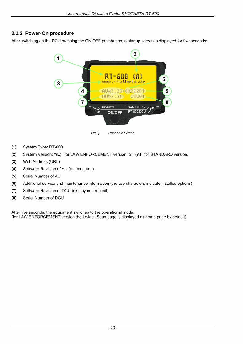
User manual Direction Finder RHOTHETA RT-600
- 10 -
212 Power-On procedure
After switching on the DCU pressing the ONOFF pushbutton a startup screen is displayed for five seconds
Fig 5) Power-On Screen
(1) System Type RT-600
(2) System Version ldquo(L)rdquo for LAW ENFORCEMENT version or ldquo(A)rdquo for STANDARD version
(3) Web Address (URL)
(4) Software Revision of AU (antenna unit)
(5) Serial Number of AU
(6) Additional service and maintenance information (the two characters indicate installed options)
(7) Software Revision of DCU (display control unit)
(8) Serial Number of DCU
After five seconds the equipment switches to the operational mode (for LAW ENFORCEMENT version the LoJack Scan page is displayed as home page by default)
User manual Direction Finder RHOTHETA RT-600
- 11 -
213 Main Pages Selection
Two main modes can be selected from the DCU front panel
DF Mode Page displays all relevant operational bearing information depending on the type of signal being received
FREQ SELECTION Page allows to access and edit all pre-programmed frequency memory channels
Fig 6) Page Selection
(1) The gtPagelt rotary switch is used to select the active page
(2) The active page is highlighted with dark background
(3) The inactive page which may be selected is displayed in dark letters on bright background
214 Dimming function
The background of the LC-graphic display is equipped with an LED array and its brightness may be adjusted continuously from 5 to 100 Dimming follows an exponential curve resulting in very accurate adjustment under night conditions
Fig 7) Dimming Adjustment
(1) Pressing the gtRepDIMlt button for a short time activates the
DIMMING mode
(2) Brightness actual information in percentage from 5 to 100 in 5 steps is displayed instead of the ldquoPagerdquo field in the upper right corner of the display
(3) The gtPagelt knob is used to adjust the brightness in 5 steps left and right
The active brightness level of the display will remain stored after switching off the unit separately for day and nightNVG mode
After ca 3 sec of inactivity the display will fall back to the prior main page Dimming of legends can be adjusted in two ways
Internal dimming of legends
Internal dimming is always active If an external dimming voltage is not used or is lt 1V DC legends are dimmed in the same manner as the LC display
External (remote) dimming of legends
If the external dimming voltage is gt 1V DC the brightness of the legends is controlled by the external dimming voltage (Refer to the wiring plan and to the operatingsetup-menu description)
User manual Direction Finder RHOTHETA RT-600
- 12 -
215 Squelch Operation
The main challenge of operating a direction finder is trying to use only the signal transmitted by the target in order to calculate its bearing accurately because noise and RF disturbances will cause misleading bearing indications In order to prevent the direction finder to calculate bearing results which are due to noise and disturbances several techniques are available If a signal can be distinguished from noise or other signals by its message content (eg LoJack ID) only transmissions containing the required message content are used for bearing In other cases the squelch can be used to suppress unwanted weak signals and noise A squelch level called threshold has to be set by the user or automatically by the system All signals with strength below this threshold value will be ignored while signals with strength above this level will cause a bearing indication So for a signal to be usable for bearing calculation it has to be sufficiently stronger than noise or disturbing signals that the receiver can clearly distinguish between wanted and unwanted signals As a result of the squelch technique the receiver sensitivity is reduced to the level set by the squelch threshold decreasing the maximum distance or range to the transmitter However it might be desirable to obtain bearing information even for weak signals which are very close to the noise level In this case it will be necessary to reduce the squelch level below the noise level As soon as the modulation of a signal can be heard on the speaker it can be expected that bearing calculation is possible If the noise is randomly distributed ndash as with ldquowhite noiserdquo ndash and no other signal is received the bearing indication will also be random If the noise is not random but rather a specific disturbance the bearing indication will point to the source of the noise If there is a very weak signal ldquoburiedrdquo in the noise this signal will produce a correct bearing indication thanks to sophisticated bearing technologies used in the RT-600 system Fluctuations due to noise will be small even at low signal levels however the reaction time of the bearing indication can increase To verify if a bearing indication is due to white noise or to an internal disturbance source or if it is due to a valid signal the aircraft should make a slow turn If the bearing indication is due to an external signal eg a SAR beacon the bearing indication should compensate the changed relative flight angle Example with a bearing indication of 30deg The signal is hardly audible as it is buried in the noise The airplane makes a turn left by 60deg If the bearing indication is not changing to approximately 30deg+60deg = 90deg after a few seconds the bearing is likely to be due to noise or internal disturbances from the aircraft Note The weaker a signal is the longer it will take to change the bearing Durations around 5 seconds are not unfamiliar in such cases Therefore it is not useful to use this procedure for signals with short transmission times and low transmit duty cycles such as COSPAS-SARSAT transmission The procedure is best suited for ELT transmission with a continuous signal and still well-suited for ELTs with intermittent transmission (down to 33) In cases where pulsed signals are to be received the receiver is able to decide automatically which squelch level is best-suited for normal operation In such cases an automatic (ldquoArdquo) squelch is provided The threshold is automatically set to a value higher than the calculated noise level The difference in dB between noise and threshold level can be defined in the Setup Menu Refer to the chapter ldquoSetup Pagerdquo for details During AUTO squelch operation the user has the possibility to force the squelch into MANUAL mode but needs to be aware of the operational limitations described in this chapter In cases where the Antenna Unit checks signal validity autonomously and without useful possibilities of user interaction user interaction is not possible and the squelch purely follows internal rules appropriate to the type of signal received
User manual Direction Finder RHOTHETA RT-600
- 13 -
Examples of different squelch settings
Fig 8) Manual squelch mode correct squelch
adjustment
Correct squelch adjustment If the squelch is set to level (b) slightly over the noise level (a) the receiver audio output remains quiet and no wrong noisy bearing is indicated
Fig 9) Manual squelch mode Incorrect squelch
adjustment
Incorrect squelch adjustment If the squelch level is set (b) below the noise level (a) a wrong noisy bearing is indicated
Fig 10) Automatic squelch mode
Automatic squelch mode Automatic squelch mode is indicated by an ldquoArdquo (c) above the squelch level marker Depending on the SN-Ratio setting the squelch level is automatically set slightly higher than the noise level Using the SQL rotary switch (1) the user can change to manual squelch mode Automatic squelch mode can be activated again by setting the squelch level manually to lt 0 or gt 60
Fig 11) Automatic squelch mode with strong signal
Automatic squelch mode with strong signals Strong short receive signals will not modify the squelch level setting
Fig 12) Automatic squelch mode and not adjustable by
the user
Automatic squelch mode level not re-adjustable by user When the squelch is adjusted automatically by the system and the user is not allowed to change it an ldquoXrdquo (c) is displayed above the squelch level marker
User manual Direction Finder RHOTHETA RT-600
- 14 -
22 Frequency (FRQ) Selection Page The Frequency Selection (FRQ Selection) Page allows the user to select a frequency select a band and edit a frequency
Open FRQ Page
From the ldquoDFrdquo standard page activate the Page Rotary Switch in any direction to open the ldquoFRQrdquo Page for Frequency Selection
Fig 13) Open FRQ Page
Fig 14) FRQ ndash Frequency Selection Page
221 Selecting a Frequency
(1) Use the Page knob ldquoFRQrdquo again to select (recall) a frequency from
gtMEMlt four (4) memory channels gtWlt one (1) working (operating) frequency gtFIXlt fixed frequencies gtCPSARlt seven (7) COSPAS-SARSAT channel groups
(2) The actual adjusted frequency
(3) Frequency band-information
Exit Frequency dialogue
(4) Press push-button gtF1lt ldquoEXITrdquo to exit to DF mode (using the actual frequency
222 Recalling and editing frequencies from a memory channel
Recall
(1) With changing the Page rotary knob memory channels 1 4 can be selected The gtmarkerlt symbol indicates the actual memory channel
Edit
(2) MHz plusmn edits the MHz Value of the actual frequency
(3) kHz plusmn edits the kHz Value of the actual frequency
(4) F2 switches to next band
gtMHzlt and gtkHzlt directly changes and overwrites the actual selected memory frequency inside the actual band (see also 224 Editing a Frequency)
Fig 15) Recall frequency of Memory channel 3
User manual Direction Finder RHOTHETA RT-600
- 15 -
223 Recalling frequencies from fixed frequencies or CospasSarsat Channels
Fig 16) FRQ Selection Page with FIX1 selected
(1) ldquoFIXrdquo Selection range for fixed frequencies
for RT-600 Standard version for RT-600 Law Enforcement version
FIX1 ldquoEltPlbrdquo 121500 MHz international VHF air distress emergency frequency
FIX2 ldquoChnl16rdquo 156800 MHz marine VHF emergency radio channel 16
FIX3 ldquoEltMILrdquo 243000 MHz military UHF air distress emergency frequency
FIX1 ldquoEltPlbrdquo 121500 MHz international VHF air distress emergency frequency
FIX2 ldquoChnl16rdquo 156800 MHz marine VHF emergency radio channel 16
FIX3 ldquoLE(USA)rdquo 173xxx MHz LoJack Recovery System
FIX4 ldquoETSSTDrdquo 216487 MHz ETS standard frequency
FIX5 ldquoETSUCVrdquo 216512 MHz ETS ucover frequency
(2) ldquoCPSARrdquo Selection range for Cospas Sarsat channel groups
CPSAR1 ldquo022-028rdquo 406022 hellip 028 MHz Channel A B C
CPSAR2 ldquo031-037rdquo 406031 hellip 037 MHz Channel D E F
CPSAR3 ldquo040-043rdquo 406040 hellip 043 MHz Channel G H
CPSAR4 ldquo046-052rdquo 406046 hellip 052 MHz Channel I J K
CPSAR5 ldquo055-061rdquo 406055 hellip 061 MHz Channel L M N
CPSAR6 ldquo064-070rdquo 406064 hellip 070 MHz Channel O P Q
CPSAR7 ldquo073-076rdquo 406073 hellip 076 MHz Channel R S
User manual Direction Finder RHOTHETA RT-600
- 16 -
224 Editing a Frequency
While on the FRQ SELECTION Page the user can directly edit the frequency displayed
Fig 17) FRQ Selection Page before frequency editing
(1) gtMHzlt Rotary switch for direct adjustment of the displayed MHz range inside the actual band
(1 x step = 1 MHz adjustment)
(2) gtkHzlt Rotary switch for changing the displayed kHz frequency according to the actual band frequency grid (as example 8333 kHz at the VHF airband)
(3) gtF2lt Adjustment of the next available band (see next page gtgt Selecting a Frequency Band)
Fig 18) FRQ Selection Page after frequency editing
If the selected and marked frequency is not one of the MEM [14] channels then the changed frequency is automatically stored in the work frequency WorkFRQ channel
User manual Direction Finder RHOTHETA RT-600
- 17 -
225 Selecting a Frequency Band
While on the FRQ Selection Page each available band can be selected by pressing F2 BAND
(1) Press push button F2 BAND for
switch over to the next band
(2) Designation of actual selected band
(3) Max frequency limits of the actual selected band (depends on wide band options)
Fig 19) FRQ Selection Page (bands)
Frequency bands availability depends on the system version (A LE) and its wide band options (F1 to F4) These optional wide bands are available if ordered in addition to the default bands Here is a listing of DEFAULT and OPTIONAL bands available with each version of the system RT-600 (STANDARD) Listing of bands
Default bands available OPTIONAL extended bands available
Band designation Frequency limits Option Designation Frequency limits
VHF Emergency Band 118000 hellip 124000 MHz gt F1 VHF Air Band 118000 hellip 136992 MHz
VHF Marine Band 154000 hellip 163000 MHz gt F2 Extended VHF Marine 137000 hellip 224995 MHz
UHF Emergency Band 240000 hellip 246000 MHz gt F3 UHF Air Band 225000 hellip 399975 MHz
COSPAS SARSAT 400000 hellip 406092 MHz
UHF FM Band 406100 hellip 410000 MHz gt F4 Additional UHF FM 406100 hellip 470000 MHz
RT-600 (Law Enforcement) Listing of bands
Default bands available OPTIONAL extended bands available
Band designation Frequency limits Option Designation Frequency limits
VHF Emergency Band 118000 hellip 124000 MHz gt F1 VHF Air Band 118000 hellip 136992 MHz
VHF Marine Band 154000 hellip 163000 MHz gt F2 Extended VHF Marine 137000 hellip 163000 MHz
LoJack 164000 hellip 174000 MHz
ETS 216000 hellip 220000 MHz
COSPAS SARSAT 400000 hellip 406092 MHz
User manual Direction Finder RHOTHETA RT-600
- 18 -
23 Direction Finder (DF) Mode Direction Finder (DF) mode is generally used to display all valid information processed by the DF from the signal received from a target transmitter The amount and kind of information displayed by the DCU depends on the type and content of the signal received and processed by the DF Simple signals such as the analog sweep-tone modulation received from a SAR beacon (ELT PLB EPIRB PDD) on 121500 MHz allow displaying only basic bearing information while digital signals such as COSPAS-SARSAT and LOJACK allow displaying more information for ex beacon IDs GPS coordinates codes VLUs etc
231 Operating Elements in DF Mode
Fig 20) Operational Elements in DF Mode
This picture shows the DCU operating in DF Mode on the international emergency frequency 121500 MHz
with an active signal being received (1) gtFREQUENCYlt Rotary switch activates the ldquoFRQrdquo frequency page for changing and selecting the
active frequency The last selected frequency remains stored after switching offon the device The selected frequency is shown on the graphic display bottom right Above additional information for the selected frequency is displayed The use of the rotary switch activates a sub-page Please refer to the Frequency Selection section for details
(2) gtVOLUMElt Rotary switch to adjust the audio output level The volume of a linked external speaker or amplifier can be adjusted in a range from 0 (off) to 99 (maximum loudness) The selected volume is shown in the bottom left corner of the graphic display The volume remains stored after switching offon the device
(3) gtSquelch Levellt adjusts the squelch level The squelch level has to be above the receiving level without signal (noise) Only signals above the squelch level are audible in the loudspeaker and used by the direction finder for bearing indication The gtSQLlt rotary switch allows to select the squelch threshold ie a minimum signal strength of an incoming signal to be processed The current settings on a signal level scale from 0 to 60 is shown in bright letters on dark background below the SQL rotary switch and as an arrow beside the signal Strength Bar-Graph
(4) The gtCLRlt Push-button is used for erasing the internal bearing value averaging store and the Last Signal Timer To activate this function the push-button has to be hold down for a minimum of circa two seconds The sophisticated averaging store increases bearing precision and enables at all an usable
User manual Direction Finder RHOTHETA RT-600
- 19 -
bearing display in case of bad receiving signals (if there is a far away transmitter andor temporary complete loss of a receiving signal) Caused by the averaging procedure a drag error may occur which might be disturbing the bearing indication after a quick change of course of the aircraft or vehicle In this case the indicated bearing value lags by the real bearing value for about two seconds (for very weak signals even longer) By pressing this push-button after a quick change of course the display will show the new bearing value without drag error Additionally the F1CLR Push-Button is used to activate specific functions high-lighted in the menu below the button by pushing it for a short time (here as example ldquoSCANrdquo starts scanning the actual air band)
(5) gtSTORElt push-button Without function except if a special function is high-lighted in the menu line of the display
(6) gtREPEATlt Push-button when pressed and hold for min 3 sec the last valid bearing value with corresponding receiving level is displayed
232 Standard Display in DF Mode
Fig 21) DF Mode
(1) gtRelative Bearing valuelt by means of a sophisticated averaging procedure a steady display is
accomplished as graphic display and as text in the range of 0deghellip 359deg (0deg corresponds to bearing direct ahead)
(2) gtSpreadlt maximum deviation of un-averaged bearing values This is an indicator of bearing quality The wider the range between the directions of maximum deviation the worse the received signal is As a result of the excellent averaging procedure even with a spread of 45deg good bearing results are achieved
(3) gtReceiving levellt (field strength) of the signal as a relative percentage value visualized as bar-graph indication and as decimal value Even without a received signal a certain noise level may be displayed
(4) gtSquelch levellt (independently adjustable and stored for each frequency band) Squelch level is indicated as marker at the Signal Strength Bar-Graph or as direct relative level value A usable bearing analysis can only be achieved if the squelch level is above the noise level (without received signal) If the antenna unit is placed close a heavily disturbing electronic devices the squelch level has to be raised thus making the direction finder being less sensitive In receive modes where the squelch level is set automatically an ldquoArdquo above the marker indicates the ldquoAutosquelchrdquo functionality
(5) gtLast Signallt timer showing the time since a signal has been received for the last time (ie since a signal has been stronger than the squelch level) Values are ldquominutes secondsrdquo
User manual Direction Finder RHOTHETA RT-600
- 20 -
233 Special Options in COSPAS-SARSAT DF Mode
Especially for the use together with beacons transmitting a data signal according to COSPAS-SARSAT specifications in the 406-MHz-Band special functionalities and pages are being provided After selection of a COSPASSARSAT Frequency (Refer to the chapter ldquoFrequency selection Pagerdquo) the bearing page provides additional information and operating options
Fig 22) Operational Elements and Display in COSPAS-SARSAT DF Mode
(1) gtAuto Squelchlt indication indicating that the squelch level is set automatically to be close to the noise
floor It is recommended to always use the Auto Squelch during COSPAS-SARSAT operation This can be achieved by manually selecting 0 (lowest possible value) or 60 (highest possible value) as squelch level During COSPAS-SARSAT-Operation this will force the automatic setting of the level
(2) gt121500lt menu option The COSPAS-SARSAT signal in the 406 MHz band is transmitted only every 50 seconds in form of a short data burst of 440 or 520 ms approaching the transmitter it will be received earlier than the 121500 MHz continuous signal due to its high transmitter power However in a lower distance to a transmitter bearing on 121500 MHz is faster thanks to the continuous or rapidly intermittent signal The 121500 MHz menu option allows a direct switch-over to 121500 MHz Direct return back from 121500 to the COSPAS-SARSAT band is possible from the 121500 MHz bearing Window in COSPAS-SARSAT mode Please refer to the chapter ldquo121500 MHz bearing Window in COSPAS-SARSAT moderdquo for details
(3) gtDecodelt menu option allows to open the COSPASSARSAT Decode sub-page by shortly pushing the F2 push-button above the menu option
(4) gtFrequency rangelt indication COSPAS-SARSAT is using a channel spacing of 3 kHz for its beacons Due to the internal architecture of the direction finder it is possible to receive more than one channel in the same time Thus frequency steps of the direction finder are 833 kHz instead of 3 kHz The receive frequency covered by the current receive frequency setting is shown in the display line above the receive frequency indication
Important If the exact frequency of the COSPAS-SARSAT beacon is unknown it is strongly recommended to use the COSPAS-SARSAT scanning functionality in order to detect the correct frequency (Refer to the chapter ldquoFrequency selection Pagerdquo amp ldquoCOSPAS-SARSAT Scan Moderdquo)
User manual Direction Finder RHOTHETA RT-600
- 21 -
234 COSPAS-SARSAT Decode Window
The COSPAS-SARSAT Decode Window allows decoding incoming COSPAS-SARSAT data messages Only while this decode window is activated the decoding is possible An already received COSPAS-SARSAT puls while DF bearing mode was activated can not be used for decoding afterwards In this case the user has to wait while this decode window is active for the next transmitted puls approx 50 sec later
Fig 23) COSPAS-SARSAT Beacon Information Page
(1) gtExitlt push button (F1 button) allows to exit the decode window and switch back to the COSPAS-
SARSAT DF Mode page
(2) gtSARSATlt in the upper right corner of the display indicates that the COSPAS-SARSAT decode function is activated
(3) gtCountrylt displays the COSPAS-SARSAT Country Code coded into the received data message
(4) gtLast Signallt time since the last COSPAS-SARSAT message has been received in minutes secondsrsquo format
(5) gtPositionlt field showing in case of location protocols being used by the beacon the encoded GNSS position data (latitude longitude) transmitted by the beacon
(6) gt15-HEX-IDlt 15-HEX-ID of the beacon in hexadecimal format
(7) gtData stringlt of the bits 25 to 112 of the COSPAS-SARSAT data burst in case of short messages and bits 25 to 144 in case of a long message format The last 8 Hex Values are separated by a blank Bit- and Frame-synchronization hex values (Bits 1 to 24) are suppressed to increase the readability of the data message
(8) gtXlt sign to indicate that the Squelch is controlled by the antenna unit for optimum sensitivity The user has no access to the Squelch setting
User manual Direction Finder RHOTHETA RT-600
- 22 -
235 Tracking 121500 MHz while in COSPAS-SARSAT Mode
While in COSPAS-SARSAT DF Mode the user can switch to 121500 MHz in order to track the beacon in VHF If a valid signal is not received in 121500 MHz the user can switch back to the last active COSPAS-SARSAT channel (406 MHz frequency) being tracking previously
Fig 24) Tracking 121500 MHz while in COSPAS-SARSAT Mode
Differences are (1) gt406xlt press F1 to switch back to the last
COSPAS-SARSAT channel (406 MHz frequency) being tracking previously
(2) gt121500 MHzlt Actual frequency being tracked
User manual Direction Finder RHOTHETA RT-600
- 23 -
236 COSPAS-SARSAT Scan Mode
If the COSPAS-SARSAT Scan Mode has been selected at the frequency selection page ldquoFRQrdquo the COSPAS-SARSAT channels as selectable manually from the Frequency Selection Page are scanned After reception of a COSPAS-SARSAT Signal the scanning is stopped at the received frequency Due to the fast scanning ndash the complete COSPAS-SARSAT sub-band is scanned within less than 400 ms ndash detection of a receivable COSPAS-SARSAT signal is possible within one COSPAS-SARSAT repetition cycle
Fig 25) FRQ Selection Page with SCN COSPAS-SARSAT Scan Page selected
At the frequency selection page an active COSPAS SARSAT scanning can be stopped by de-activating it with the rotary button (1) While the scanning is active it is also possible by pressing gtF1lt ldquoEXITrdquo to switch back to the DF pagehellip
Fig 26) DF page with active COSPAS-SARSAT Scan Mode at the DF page
(1) gtSCANlt flashing indication notifying the user that the equipment is operating in scan mode
(2) Frequency display indicating the COSPAS-SARSAT scanning frequency range
(3) gtXlt sign showing that squelch settings are controlled autonomously by the receiver
Scan mode can be left by pressing gtF1lt ldquoSTOPrdquo
User manual Direction Finder RHOTHETA RT-600
- 24 -
237 Marine Ship Scan Mode
Fig 27) DF Mode FRQ = 156800 MHz F1 for scan function
If the active frequency (2) is within the VHF Marine Band a fast scan of all ship channels is possible by pushing gtF1lt ldquoSCAN (1) In this scanning mode all marine channels 1 to 88 (156025 to 157450 MHz) are scanned continuously until a signal is received To offer the best monitoring functionality for the user also signals between to channels (4) are detected (scanning without gap) In order to prevent the scan to stop on noisy frequencies it is recommended to start scanning with high squelch settings You can reduce the squelch level in steps until the scan stops on a noisy frequency for the first time Then increase the squelch level slightly This will result in the highest possible scan sensitivity and avoiding noisy channels due to RF disturbances sometimes generated by other equipment in own aircraft
Fig 28) DF Mode active scanning in process
The scanning is stopped by pressing gtF1lt ldquoSTOPrdquo (3)
User manual Direction Finder RHOTHETA RT-600
- 25 -
24 Law Enforcement Operation Law enforcement special ops and other organizations use the RT-600 LE (LAW ENFORCEMENT) version instead of the RT-600 A (STANDARD) version One of the reasons is that the LE version features scanning and tracking of signals like LoJack and ETS as well as signals in the 216000 MHz ndash 220000 MHz band such as medical beacons wristankle transmitters cashasset recovery ldquotagsrdquo etc However the LE version shares many functions in common with the A version such as scanning and tracking in the AIR band COSPAS-SARSAT band etc
241 Power-On procedure
The power-on procedure is the same as described in 211
(1) System Version ldquo(L)rdquo for LAW ENFORCEMENT version
Fig 29) STARTUP Screen (see 211 for details)
242 LoJack Scan Mode Start scanning for a VLU Code
For the convenience of Law Enforcement and other special ops users who frequently engage in tracking SVRS (Stolen Vehicle Recovery System) signals such as LoJack (LoJack Corp FCC 9020 Part 2 SVRS) RHOTHETA has optimized the power-on procedure of the RT-600 LE version so that right after the STARTUP screen the unit displays automatically the LoJack Scan Mode page to start immediately scanning for a valid VLU (Vehicle Location Unit) code without pressing any key
Fig 30) LoJack Scan Mode unit is scanning for a LoJack VLU Code
(1) gtscan LoJacklt DF is scanning for any new LoJack VLU Code
(2) gtEXITlt press F1 to exit and switch directly to DF Mode
User manual Direction Finder RHOTHETA RT-600
- 26 -
243 LoJack Scan Mode from any other page
While operating on any page other than the LoJack Scan page the user can switch directly to LoJack Scan Mode by pressing Hotkey F2 for 2 secs
(1) press Hotkey F2 for 2 secs to switch to the LoJack Scan page
Fig 31) Hotkey F2
User manual Direction Finder RHOTHETA RT-600
- 27 -
244 Manual activation of LoJack Scan Mode
(1) select the LoJack frequency (see also Frequency Selection Page)
(2) press F1 to switch back to the DF MODE
Fig 32) FRQ Selection Page FRQ = LoJack BAND = LoJack (164-174 MHz)
While in DF MODE with adjusted LoJack frequency the user can switch directly to the LoJack Scan by pressing gtF1lt ldquoSCANrdquo
(1) press F1 SCAN to switch to the LoJack Scan page
(2) still no LoJack ID filter used (ID=off) all transmissions are received on the active frequency as example also unwanted tower pulses
Fig 33) DF Mode with LoJack filter OFF
User manual Direction Finder RHOTHETA RT-600
- 28 -
245 Receiving and accepting a new VLU Code
While in LoJack Scan Mode waiting for a VLU Code if a new VLU Code is displayed the user can accept it and switch directly to DF Mode by pressing F2
(1) a new LoJack VLU Code (0001A) has been received
(2) press F2 to accept the new VLU Code (0001A) and switch to DF MODE page with the LoJack filter activated to track only 0001A
Fig 34) LoJack Scan Mode with new VLU Code received
246 Entering a new VLU Code manually
While in LoJack Scan Mode the user can enter a LoJack VLU code also manually
(1 2 3) use the SELECTplusmn and plusmnVALUE knobs to enter a new LoJack VLU Code active ID (0001A)
(4) Press F1 to accept the new VLU Code and switch to DF Mode with the LoJack filter ON to track only 0001A
Fig 35) LoJack Scan Mode with new VLU Code entered manually
User manual Direction Finder RHOTHETA RT-600
- 29 -
247 Tracking one VLU Code while monitoring new VLU Codes
While on DF Mode and tracking a VLU Code (0001A) the user can turn the LoJack switch OFF with F2 also the user can start scanning all VLUs again with F1
0001A is displayed as the active VLU Code filter function is ON only 0001A is tracked
Monitoring of other VLU Codes is active in the background
(1) Press F1 to switch to the LoJack Scan Mode to scan for new VLU Codes
(2) Press F2 to switch LoJack filter OFF
Fig 36) DF Mode with active VLU Code and LoJack filter ON
248 Tracking one VLU Code and receiving a new VLU Code
While on DF MODE page and tracking VLU Code (0001A) in the background a new VLU Code is received and decoded (G2HC7)
(1) The new VLU Code is announced (NEW G2HC7)
(2) Press F1 to switch to LoJack Scan Mode to see the arrival time of G2HC7 and the possibility to change bearing to this new G2HC7
Fig 37) DF Mode with active VLU Code and announcement of new VLU Code
User manual Direction Finder RHOTHETA RT-600
- 30 -
249 Switching to a new VLU Code
While on the LoJack Scan Page tracking one VLU Code (0001A) and notified of a new VLU Code (G2HC7)
(1) press F1 to continue tracking 0001A
(2) press F2 to start tracking G2HC7
(3) Time elapsed since G2HC7 was last received
(4) Time elapsed since 0001A was last received
If F1 is pressed for 2 sec the indicated VLU Code (G2HC7) and ID (0001A) are deleted
Fig 38) LoJack Scan Page with one active VLU Code and one new VLU Code
2410 ldquoBlockingrdquo function of one LoJack VLU Code
The LoJack scan page can also be used to ldquoblockrdquo one unwanted LoJack VLU ID signal by separating the adjusted active ID from any other received LoJack VLU signal This is done by muting the audio (see example below) when a LoJack signal with VLU code ldquo0001Ardquo is received gtgt Any new VLU Code (active LoJack signal) - except for 0001A ndash will be displayed on the top row and generate the audible beep tone
Fig 39) LoJack Scan Page with one active VLU Code and audio OFF
Tip ldquoBlockingrdquo is an important tool for practical missions As example a stolen vehicle with VLU ID ldquo0001Ardquo was tracked in the DF bearing mode The mission
is completed but the VLU is normally still transmitting With the settings above only new VLU signals except the now unwanted ldquo0001Ardquo are audible and displayed in the upper (scan LoJack hellip for new VLU) box
User manual Direction Finder RHOTHETA RT-600
- 31 -
2411 Tracking in the 216 to 220 MHz band
The RT-600 features scanning and bearing functionality in the 216000 MHz to 220000 MHz band The 216000 MHz ndash 220000 MHz band contains frequencies and signals used by special services and tracked by law enforcement special ops and similar organizations These are some of the frequencies and services in this band
CFR 90259 tx 216000 MHz to 220000 MHz
Low Power Radio Service (LPRS) tx 216000 MHz to 217000 MHz
Medical beacons Project Lifesaver tx wristankle tx 213000 MHz to 216000 MHz
ETS tx stolen cashasset recovery tx ldquobaitrdquordquotagrdquo tx 216000 MHz to 220000 MHz tx = transmitter(s) However any future or current user of the Rhotheta RT-600 must be aware that tracking signals on the frequencies listed above may be challenging and even frustrating due mostly to negative factors in some of the transmitters
bull Very low RF power output
bull Inefficient antennas
bull Battery-powered devices with a ldquolow batteryrdquo condition
bull Devices worn or located in conditions of poor RF propagation
bull Devices with channel spacing different than the one specified for the RT-600
These factors can make it very difficult for the DF to receive the signal andor display an accurate bearing Disclaimer For the reasons explained above and even though the RT-600 features top performance in its class RHOTHETA does not offer - and is not to be held responsible for - any guaranteed minimum range or distance to a transmitter in this band
25 Setup Edit Page System settings are displayed in the setup page The functions described in this section should be used by trained personal only
Fig 40) Accessing the Setup Page
The setup page can be accessed by holding down the gtCLRlt (1) and gtREPlt (2) buttons simultaneously and in the same time performing a left-hand turn on the gtPagelt rotary switch (3)
User manual Direction Finder RHOTHETA RT-600
- 32 -
Fig 41) Setup Page
(1) gtStorelt push-button must be pressed in parallel if a value of a setting shall be modified If a value can
be modified the background stops to blink
(2) gtSelectlt rotary switch used to scroll through the menu options The value of the actually activated menu option is high-lighted with dark background and blinking
(3) gtValuelt rotary switch used to change values in menu options (gtStorelt (1) has to be pressed in parallel if a value shall be modified)
(4) gtSN-Ratiolt menu option representing the necessary Signal-To-Noise-Ratio (Difference between signal and noise level) used as criterion for the automatic squelch function Please refer to the chapter ldquoSquelch Operationrdquo for details Default value is 60 dB
(5) gtMounting Positionlt menu option to select Top- or Bottom-Mounting of the DF antenna In case of rooftop installation (eg on land vehicles) ldquoToprdquo shall be selected In case of bottom-down (upside-down) installation (eg on a helicopter) ldquoBotrdquo shall be selected If this option is not selected correctly all bearing values will be mirror-inverted
(6) gtBearing Offsetlt menu option to include a constant offset correction to the bearing indication Bearing values in degrees will be changed according to the offset value
(7) gtMaximum External Dimming Voltage for Legendslt menu option which sets the upper limit of the dimming input voltage for the legends-panel Range=[15 hellip 28]V
(8) gtMinimum External Dimming Voltage for Legendslt menu option which sets the lower limit of the dimming input voltage for the legends-panel Range=[15 hellip 28]V
(9) gtPagelt rotary switch to be turned right-hand to go back to the Direction Finder page A left-hand turn on this rotary switch will show up an additional service page with debug information used for system checks
(10) gtExtended Seriallt It is possible to enable or disable the extended serial data protocol Only of interest if serial data is used by any connected control units like moving maps or computers For detailed information see (Serial interface data protocol (short description)gt at page 46) If there are compatibility problems with already existing older remote control software it is recommended to switch OFF the extended serial data protocol
User manual Direction Finder RHOTHETA RT-600
- 33 -
3 Error messages If an internal error of the device is recognized a corresponding flashing error message will be shown in the DF pages
Fig 42) Error Messages
(1) Error message including error code (in brackets)
(2) Short description of the indicated error
In case of coincidence of various errors the error with the highest priority will be displayed
Error message Error location Reason
Error (12) VOLTDU
Main voltage supply Main Voltage input too low ( 100 V)
Error (11) NO AU
Connection antenna display or Antenna Unit
No serial data (RS485) from Antenna Unit No or damaged connection between antenna and display or damaged antenna unit
Error (10) BAD AU
Connection antenna display
Incompatibility or bad data connection between display and antenna
Error (9) BAD RU
Remote Unit Incompatibility or bad data connection between display and external serial Remote Unit or PC
Error (8) VOLTAU
Antenna Unit Voltage supply at Antenna Unit too low ( 90 V) Main voltage supply too low or considerable drop of voltage between display and antenna
Error (7) BAD DCU
Connection Display Antenna
Incompatibility or bad data connection between antenna and display
Error (6) NO DCU
Connection Display Antenna
No serial data from Display Control Unit to Antenna Unit
Error (5) PLL ERR
antenna Error in synthesizer-oscillator of receiver in Antenna Unit
Error (4) FRQ+OFS
received transmitter Received frequency too high (more than 6 KHz error of transmitter)
Error (3) FRQ-OFS
received transmitter received frequency too low (more than 6 KHZ error of transmitter)
Error (2) DECODE
radio distance transmitter DF
Data Bits of decoded signal (COSPAS-SARSAT or LoJack) defective
Error (1) DATARNG
Incompatibility of data DCU AU
Protocol data bytes out of valid range
Error (0) NO REC
Antenna Unit receiver
Receiver board defective
User manual Direction Finder RHOTHETA RT-600
- 34 -
4 Installation
41 Antenna unit A convenient position of the monopole bearing antenna is crucial for good bearing results The antenna needs an effective ground connection to the body of the aircraft or to the roof of the vehicle If there is no metallic mounting surface available a metallic sheet or similar (net) with connection to ground has to be applied first between vehicle-body and antenna In this hatched area the antenna touches the body ofthe vehicleaircraft In order to obtain a good groundconnection the surface of the body should be bared(Measuring unit [mm])
8 x holes for mounting the antenna unit to the
vehicle aircraft
Fig 43) Antenna Mounting Drawing
User manual Direction Finder RHOTHETA RT-600
- 35 -
411 Influence of antenna location and environment on the bearing accuracy
Recommendations concerning the practical antenna unit location on helicopters and airplanes
The bearing accuracy of the direction finder antenna unit is severely influenced (comparable to an airspeed sensor) by the environment For comparison a perfect high quality speed sensor will not indicate the true airspeed if this sensor is interfered by strong turbulences The direction finder antenna unit acts as a sensor for electromagnetic waves In the near field of this antenna unit any conductive (eg metallic) obstacle will influence the incoming wave field and create reflections which decrease the bearing accuracy These are general physical limitations concerning all types of direction finder systems To achieve the best bearing results it should be considered that the antenna unit is installed as far away as possible from any other vertically polarized conductive structure If possible there should be no reflectors within an area of 2-3 feet around the antenna unit In this worst case example the direction finder will not work properly
Fig 44) Antenna Installed in a Bad Location
In this example the antenna unit is located too close to the cable cutter of the helicopter This cutter will produce strong reflections especially as the length is equal to Lambda4 within the VHF airband
User manual Direction Finder RHOTHETA RT-600
- 36 -
Examples of properly installed direction finder antenna units
Fig 45) Antenna Installed in Good Locations
User manual Direction Finder RHOTHETA RT-600
- 37 -
42 Display and Control Unit
The display control unit may be mounted into a front panel by the means of this mounting drawing
Fig 46) DCU Mounting Drawing
(all dimensions in [mm]) To install or uninstall the display control unit perform the following steps (1) Remove the cover caps of the four rotary switches
(2) Loose the screws visible below the position of the cover caps
(3) Remove the plastic button from the axis of the four rotary switches
(4) Mount dismount the display control unit
(5) Re-install the plastic buttons on the axis of the four rotary switches
(6) Fix the screws so that the plastic buttons are fixed on the axis
(7) Re-install the cover caps on the four rotary switches
User manual Direction Finder RHOTHETA RT-600
- 38 -
43 System Interconnect Wiring Diagram (Also refer to chapter ldquoTechnical Datardquo for details)
Fig 47) System Interconnect Wiring Diagram
6-pol Amphenol plug femalePTG06SE10-6S(SQ)
max length of cable 20 m 9-pol Sub-D plug (femalemale)
User manual Direction Finder RHOTHETA RT-600
- 39 -
5 Technical Data
51 Electric features
Method of bearing Doppler-principle (3 kHz rotational frequency right left rotation)
Bearing accuracy1 plusmn 5deg RMS
Internal resolution 1deg
Bearing Sensitivity VHF AirEmergency le 25 μVm (typical)
VHF Marine le 25 μVm (typical)
UHF Emergency and ETS le 4 μVm (typical)
COSPAS-SARSAT le 4 μVm (typical)
LoJack Decoding (50 Message Error Rate) and bearing le 5 μVm (typical)
Frequency stability plusmn 20 ppm (Δff = plusmn210-6)
Reception frequencies
SAR version (Standard)
Frequency Options
VHF Emergency Band 118000 to 124000 MHz (833 kHz steps AM)
VHF Marine Band 154000 to 163000 MHz ( 500 kHz steps FM) (channel 16 selectable via channel no)
UHF Emergency Band 240000 to 246000 MHz (2500 kHz steps AM)
UHF FM Band 406100 to 410000 MHz ( 500 kHz steps FM)
COSPAS-SARSAT 400000 to 406092 MHz Including 406022 to 406076 MHz (Channel A S)
F1 VHF Air Band 118000 to 136992 MHz
F2 extended VHF Marine Band 137000 to 224995 MHz
F3 extended UHF Air Band 225000 to 399975 MHz
F4 additional UHF FM Band 406100 to 470000 MHz
Reception frequencies
LAW Enforcement version
Frequency Options
VHF Emergency Band 118000 to 124000 MHz (833 kHz steps AM)
VHF Marine Band 154000 to 163000 MHz (500 kHz steps FM) (channel 16 selectable via channel no)
LoJack 164000 to 174000 MHz (125 kHz steps FM)
ETS 216000 to 220000 MHz (10125 kHz AM)
COSPAS-SARSAT 400000 to 406092 MHz Including 406022 to 406076 MHz (Channel A S)
F1VHF Air Band 118000 to 136992 MHz
F2 extended VHF Marine Band 137000 to 163000 MHz
COSPAS-SARSAT fast scan mode
Full automatic detection of any active COSPAS-SARSAT channel A to S within 400 ms
COSPAS-SARSAT decoding
Reception and decoding of COSPAS-SARSAT data signal (112 or 144 bit) specified according to COSPAS-SARSAT
LoJack decoding Selectable LoJack ID display and selective active filtering
Special scanning modes
complete maritime ship band scanning within 3 s (channel 01 hellip 88 also frequencies between 2 channels are included)
1With undisturbed wave field and sufficient field strength Measuring by changing the angle of incidence with the antenna rotating on a revolving table in order to eliminate environmental influences on the results No modulation
User manual Direction Finder RHOTHETA RT-600
- 40 -
Bearable modulation A3E F3E A3X (ELT-modulation) F1D G2D COSPAS-SARSAT Bearing largely independent of modulation
Polarization Vertical
Polarization error 5deg at 60deg field vector rotation
Garbling cone Ca 30deg to the vertical
Time of response2 50 ms (with sufficient reception field strength)
LC-graphic display 128 x 64 pixels supertwist transflective extended range of temperature dark-blue display on yellow-green background background light Freely adjustable (exponential) dimming of brightness
NVG cockpit design Fully compatible NVIS Green B display Control Unit optional
Operating voltage 275 V nominal 12 V to 35 V DC
Current consumption LCD-background light Off max 500 mA (12 V DC) max 250 mA (24 V DC)
LCD-background light 100 max 750 mA (12 V DC) max 350 mA (24 V DC)
LCD-background light 100 max 900 mA (12 V DC) with NVG Option max 400 mA (24 V DC)
Audio out For external speaker approx 2 W (4 Ω)
Serial data interface Serial interface RS-232 (9600 baud 8 data bits 1 stop bit no parity)
2Very weak signals can considerably increase the time of response
User manual Direction Finder RHOTHETA RT-600
- 41 -
52 Interface External connections (optional at Sub-D 9-pol Male connector)
Dimming
Pin 8
external voltage input for variable dimming of legends
(optional)
Analog input signal for variable control of the legends illumination Input voltage range is freely adjustable in the range of 15 hellip 28 V in the setup menu Refer to chapter ldquoSetup Pagerdquo Default setting 8 hellip28 V (8 V = Off 28 V = max dimming for legends)
Input Impedance gt 50 k
Pin 6 night status line for LCD
dimming (optional)
Low-active (as example switch to ground) At input voltage lt 25 VDC the LCD dimming operates in nightNVG mode Maximum brightness ca 4 of daydefault mode brightness
Input Impedance gt 50 k
Pin 4 NVG status line for LCD
dimming (optional)
Low-active (as example switch to ground) At input voltage lt 25 VDC the LCD dimming operates in nightNVG mode Maximum brightness ca 4 of daydefault mode brightness
Input Impedance gt 50 k
AudioLF
Pin 7 Audio output signal
AC coupled voltage source with very low inner resistance Maximum output voltage ca 8 VPP = 283V RMS at maximum Volume Maximum output power ca 2 W with 4 speaker
If a headphone is connected ([32hellip600] 100mW) we recommend using a resistor (18 025 W) between audio output and headphone to prevent damage of the headphone
Serial interface RS232 (9600 baud 8 data bits 1 stop bit no parity)
Pin 3 TXD Serial output (ca plusmn10 V)
Pin 2 RXD Serial input (ca plusmn10 V)
User manual Direction Finder RHOTHETA RT-600
- 42 -
53 Mechanical features
Temperature range
Display Control Unit permissible operating temperature3 -20 degC +60 degC permissible storage temperature -30 degC +80 degC
Antenna Unit permissible operating temperature3 -40 degC +60 degC permissible storage temperature -55 degC +80 degC
Protective system Antenna Unit IP 67
Weights Display Control Unit 250 g Antenna Unit 2000 g
Dimensions Display Control Unit 82 mm x 82 mm x 43 mm (width x height x depth) Antenna Unit 270 mm x 185 mm
Fig 48) DCU Mechanical Drawing (all dimensions in [mm])
3 For temperatures lower than ndash10deg C a warm-up period of 15 min should be allowed
User manual Direction Finder RHOTHETA RT-600
- 43 -
Fig 49) AU Mechanical Drawing (all dimensions in [mm])
User manual Direction Finder RHOTHETA RT-600
- 44 -
6 Appendix
61 Frequency Ranges
User manual Direction Finder RHOTHETA RT-600
- 45 -
62 Frequencies of channels on maritime band (only for standard [A] version) Frequency-range of the RT-600 in the maritime band 156000 MHz 162025 MHz
Channel No frequency (ship - station) Frequency (coast - station)
1 156050 MHz 160650 MHz 2 156100 MHz 160700 MHz 3 156150 MHz 160750 MHz 4 156200 MHz 160800 MHz 5 156250 MHz 160850 MHz 6 156300 MHz 160900 MHz 7 156350 MHz 160950 MHz 8 156400 MHz 9 156450 MHz
10 156500 MHz 11 156550 MHz 12 156600 MHz 13 156650 MHz 14 156700 MHz 15 156750 MHz 16 156800 MHz 17 156850 MHz 18 156900 MHz 161500 MHz 19 156950 MHz 161550 MHz 20 157000 MHz 161600 MHz 21 157050 MHz 161650 MHz 22 157100 MHz 161700 MHz 23 157150 MHz 161750 MHz 24 157200 MHz 161800 MHz 25 157250 MHz 161850 MHz 26 157300 MHz 161900 MHz 27 157350 MHz 161950 MHz 28 157400 MHz 162000 MHz 60 156025 MHz 160625 MHz 61 156075 MHz 160675 MHz 62 156125 MHz 160725 MHz 63 156175 MHz 160775 MHz 64 156225 MHz 160825 MHz 65 156275 MHz 160875 MHz 66 156325 MHz 160925 MHz 67 156375 MHz 68 156425 MHz 69 156475 MHz 70 156525 MHz 71 156575 MHz 72 156625 MHz 73 156675 MHz 74 156725 MHz 75 156775 MHz 76 156825 MHz 77 156875 MHz 78 156925 MHz 161525 MHz 79 156975 MHz 161575 MHz 80 157025 MHz 161625 MHz 81 157075 MHz 161675 MHz 82 157125 MHz 161725 MHz 83 157175 MHz 161775 MHz 84 157225 MHz 161825 MHz 85 157275 MHz 161875 MHz 86 157325 MHz 161925 MHz 87 157375 MHz 161975 MHz 88 157425 MHz 162025 MHz
User manual Direction Finder RHOTHETA RT-600
- 46 -
63 Serial interface data protocol (short description)
631 General
Interface parameters RS232 9600 Baud 8 databits 1 stopbit no parity LSB sent first Timing of serial data For accurate use of the serial data (even for the optional serial input commands) the correct timing is mandatory The DCU (Display Control Unit) sends out via the RS-232 Pins (see 43 System Interconnect Wiring Diagram page 38) cyclic and autonomous every approx 250300 ms a binary data stream which contains all relevant DF-bearing information The output data contains one or two blocks of binary data (see next picture with accordingly description) The optional serial input is only used if changes (as example frequency change) are done by additional remote control units
Fig 50) Timing of serial data
Serial standard output
This output data is always available and contains all relevant DF-bearing data For detailed content see page 47
Optional extended serial output
This data contains some additional information like as example CospasSarsat or LoJack decoding and ID data For detailed content see page 50 The data is only available with DCU Software [Rev ge 320] and if this optional data block is configured as ON = enabled (see Setup Edit Page point (10) )
Even to avoid compatibility problems with already existing older remote control software it is possible to disable switch off this additional data block (see Setup Edit Page point (10) )
Optional serial input
Only used for optional commands to control DCU parameters If as example the direction finder frequency is changed remotely there is send to the DCU one time this data block with the new frequency For detailed content see page 52
User manual Direction Finder RHOTHETA RT-600
- 47 -
632 Serial standard output (protocol description)
Specification serial standard output
The binary data stream with a length of 39 bytes starts with a header byte (value = hex 0xA0 as ID for DF Mode) The next bytes contain different values for status bearing information and also service The last byte is used for data stream checksum control Remark This is a binary data protocol So every byte value from 0dec hellip 255dec (0x00 hellip 0xFF) is possible Because of this it is not allowed to realize a start byte detection by the content (0xA0) The idle line detection is recommended for detection the end of message Register of databytes (for details see next page)
byte no
[0] Header = 0xA0 Id for DF Mode
[1] Number = 39 = bytes in the complete message (including header and checksumbyte)
[2] Status (1) HSB [x|x|x|x|x|x|x|x] LSB | | | | | | | --gt (0) Receiving | | | | | | ----gt (1) Squelch controlled by AU (X) | | | | | ------gt (2) Permission RL Calibration | | | | --------gt (3) Line Night | | | ----------gt (4) Line NVG | | ------------gt (5) Dimming External | --------------gt (6) Autosquelch Active ----------------gt (7) 0=Standard Version 1=LE Version
[3] Status (2) HSB [x|x|x|x|x|x|x|x] LSB | ----------------gt (7) 0=Standard 1=extended serial dataprotocol = ONactive
[45] Error (Bits[120])
[6] Actual DCU Page
[7] Volume [0hellip100]
[811] Frequency [Hz]
[12] Active Band
[13] Actual Squelchlevel [0hellip60]
[14] Audio-Line amp_NF_Test Output
[15] (Not used)
[1617] Voltage_DCU ([0hellip335]=[0 hellip 335]V
[1819] Voltage_AU ([0hellip255]=[0 hellip 255]V
[20] Temperature_AU [-68hellip+127]degC
[21] Frequency Offset [-99hellip+99]
[2225] ServiceTest values (mode dependent test values for service only)
26 (Not used reserved)
[27] Level [0hellip100]
[2829] Bearing Averaged [0hellip359]deg relative
[3031] Bearing Live_Min [0hellip359]deg relative
[3233] Bearing Live_Max [0hellip359]deg relative
[34] Test Value PS-RAM Right Rotation[0hellip178] (for service only)
[35] Test Value PS-RAM Left Rotation [0hellip178] (for service only)
[3637] (Not used reserved)
[38] Checksum is the 2rsquos complement of the modulo-256 sum of all bytes without checksum-byte [0n-1]
User manual Direction Finder RHOTHETA RT-600
- 48 -
Detailed Description of important values for practical use
Status byte [2] Receiving Bit 0 of this value (LSB) indicates signal receiving Bit 0 = 0 then no signal is received and so on no bearing is available Bit 0 = 1 then bearing is possible Bit 1 if(1) then Squelch is controlled by AU (active at modes CospasSarsat Decode CospasSarsat Scanning LoJack with Filter=ID only)
Error bytes [4hellip5] 16 bit value each set bit corresponds to the error no (Refer to the chapter Error messages) Example - 0x0000 No error - 0x0800 Bit No 11 Set ( = No AU Error)
Actual DCU Page byte [6] indicates actual operating mode of DCU 0 = Standard bearing page 1 = Frequency memory page 2 = CospasSarsat decoding page 3 = LoJack decoding page (ID edit)
Frequency bytes [8hellip11] 32 bit value actual adjusted frequency [Hz] Example - 0x073DF160 1215000000 121500 MHz
Active Band Standard Version [A] 0=VHF Airband 1=VHF Marineband sea 2=VHF Marineband coast 3=UHV Airband 4=CospasSarsat LE Version [L] 0=VHF Airband 1=LoJack 2=Lifesaver 3=ETS 4=CospasSarsat
Actual Squelchlevel byte [13] Range [0hellip60] without signal the actual squelchlevel should always be adjusted a little bit over the noise level (Refer to the chapter Squelch operation)
Level byte [27] Range [099] actual receiving level (without signal this value is equal to the noise level) If a signal is received then this value corresponds to the signal strength of this signal
Relative Bearing averaged byte [2829] 16 bit value Range [0hellip359 0xFFFF] if the value = 0xFFFF then no valid bearing is available otherwise this value contains the actual averaged bearing information in Deg [0deg359deg] Example - 0X0114 276deg bearing (= left side oriented to heading)
Bearing Live MinMax byte[3031] amp [3233] - 16 bit values Range [0hellip359 0xFFFF] Only for signal quality or additional information ndash NOT recommended for bearing indication The relative live bearing field contains the maxmin bearing in degrees without averaging The relative live bearing reacts faster than the normal relative bearing but it has not the precision of the averaged bearing The MinMax Bearing Values are calculated within a time period of approx 250 ms If they are very close together (for example ldquo124rdquo and ldquo128rdquo degrees) then the signal quality is quite good A wide span of the minmax values (for example ldquo97rdquo and ldquo162rdquo) shows very noisy but nevertheless bearable signal quality
User manual Direction Finder RHOTHETA RT-600
- 49 -
633 DCU Info output (protocol description)
Specification DCU Info output
Remark This protocol is only available while the SetupEdit page is activated at the DCU
byte no
[0] Header = 0xAF Id for DCU Info Mode
[1] Number = 39 = bytes in the complete message (including header and checksumbyte)
[2]
(see standard output) [3]
[45]
[621] Info String of 15 byteschars the string contains Information about Unit Variant Software Version and Serial No
Example Byte [318] =
|--AU ID---||Var-||---Software Version---| |-------------- Serial No---------------| [0x44][0x55][0x41][0x33][0x2E][0x33][0x30][0x3A][0x20][0x20][0x30][0x31][0x32][0x33][0x34][0x00] rsquoDrsquo rsquoUrsquo rsquoArsquo rsquo3rsquo rsquorsquo rsquo3rsquo rsquo0rsquo rsquorsquo rsquo rsquo rsquo rsquo rsquo0rsquo rsquo1rsquo rsquo2rsquo rsquo3rsquo rsquo4rsquo rsquoENDrsquo | | | | __________________ | | ________________________ | n n n | | n n n n n | (Software Version) | | (Serial No) | gt rsquoArsquo = Standard Variant gt rsquoLrsquo = Law Enforcement Variant
User manual Direction Finder RHOTHETA RT-600
- 50 -
634 Optional extended serial output (protocol description)
The data content depends on the actual mode of the direction finder To get special data the direction finder has first to be switched to the equivalent mode
COSPAS-SARSAT Decoding data
This data is only available and valid if Display Control Unit with actual software Rev ge 320 (see Power-On procedure page 10) Configuration of Extended serial = ON (see Setup Edit Page point (10) ) Direction Finder COSPAS-SARSAT decoding mode is activated by selecting the corresponding page
(see COSPAS-SARSAT Decode Window page 20 and page 21) and so on Header (byte 0 of data) = 0x91
A valid COSPAS-SARSAT decoding data protocol is always marked by the first data byte (header = 0x91) Always after receiving and decoding of a valid COSPAS-SARSAT pulse the complete data protocol with 33 bytes is send out one time
Byte No
[0] Header = 0x91 (Identification for CPSarsat decoding mode)
[1] Number of bytes - 7 if no decoded pulse is available - 33 if new pulse was received and is available
[2] Error
[3] Bit[0] - 0 =gt No new 406 MSG (decoded data) available - 1 =gt New valid 406 MSG available (Sync amp Frame Ok) Check Error Status for Bit-Errors
Bit[61] AutoSquelch Level valid range [060] ( decimal)
Bit[7] = 1 Squelch controlled by AU
[4] Signallevel of received signal valid range [099] ( decimal)
[5] Voltage of Antenna Unit Power Supply input valid range [80255] (decimal = 80 255 V DC)
[6] Temperature inside Antenna Unit valid range [-50+100] (degC signed byte value)
The following databytes are only available if a correct CPSarsat puls gets received and decoded with correct checksum
[724] 18 x Databytes complete orginal CPSarsat 406 decoded message (144 bit)
Databyte Nr [ Byte 7 ] [ Byte 8 ] [Byte9 Byte24] 406 MSG Bit Nr [1 2 3 4 5 6 7 8] [9 10 11 12 13 14 15 16] [17 144]
[25] SN-Flag valid values 0x53=rsquoSrsquo 0x4E=rsquoNrsquo 0x2D=rsquo-rsquo if no GPS data available
GPS-Position Latitude
[26] Deg valid values [090] (decimal Deg) 0xFF if no GPS data available
[27] Min valid values [059] (decimal Deg) 0xFF if no GPS data available
[28] Sec valid values [059] (decimal Deg) 0xFF if no GPS data available
[29] WE-Flag valid values 0x57=rsquoWrsquo 0x45=rsquoErsquo 0x2D=rsquo-rsquo if no GPS data available
GPS-Position Longitude
[30] Deg valid values [0180] (decimal Deg) 0xFF if no GPS data available
[31] Min valid values [059] (decimal Deg) 0xFF if no GPS data available
[32] Sec valid values [059] (decimal Deg) 0xFF if no GPS data available
User manual Direction Finder RHOTHETA RT-600
- 51 -
LoJack ID data
This data is only available and valid if Display Control Unit with actual software Rev ge 320 (see Power-On procedure page 10) Direction Finder of variant [L] Law Enforcement Configuration of Extended serial = ON (see Setup Edit Page point (10) ) Direction Finder is working with active LoJack gtID Filterlt Header (byte 0 of data) = 0x93 or 0x94
Valid LoJack ID decoding data is always marked by the first data byte (header = 0x93 or 0x94)
Byte No
[0] Header = 0x93 LoJack ID editing sub-page is selected Filter = VLU all valid and received LoJack pulses are indicated = 0x94 Lojack Decode amp DF Mode with active Filter = ID
[1] Number of bytes in the complete data stream - decimal 26 = default value
[2] Nonrelevant
[3] Bit[0] Receiving OnOff - 0 =gt No Receiving no bearing - 1 =gt new LoJack pulse received
[412] Nonrelevant
[1317] Lojack ID
Replay Code 5 x ASCII Chars ldquoNo BIOZrdquo set
Example ASCII = ldquo000R1rdquo
18 Receiver Level Out Max [099]
19
LoJack Decoder Status [07] - 0 Off - 1 Wait for Preamble - 2 Preamble Ok - 3 FlagPattern Ok - 4 Data BitError gt 1 - 5 Data Ok (No VLU) - 6 VLU Ok - 7 ID Ok (Filter=IDONLY)
[2025] Nonrelevant
Remark Only if byte no [3] bit [0] gets ldquo1rdquo (Receiving On) then an active LoJack pulse is received and so on the corresponding LoJack ID valid otherwise the LoJack ID only shows the actual adjusted LoJack Filter ID of the direction finder
User manual Direction Finder RHOTHETA RT-600
- 52 -
635 Optional serial input (protocol description)
Specification serial input (optional)
The serial input is normally used for service and maintenance only Nevertheless it is possible via this interface to remote control the actual frequency and the squelchlevel of the DF system If a valid data stream is send to the DF then the actual frequency selection at the DCU is switched to Block2 AUX0 At this memory channel the new frequency is stored and used automatically (Refer to the chapter Frequency Selection Page) If the frequency is changed (by one valid data stream) no more serial input is necessary The actual frequency can be changed again at any time by manual operation at the DCU The timing of serial input (if used) is strictly fixed The optional serial input has to take place directly after a complete serial output (max 50 ms delay time) If a new changed frequency is commanded to the DCU via this serial input interface it can take up to 1 sec of time until this new frequency is ready for operationbearing It is strictly not recommended to use the frequency remote control for any scan mode The frequency control has to be used for static frequency change only Register of databytes
byte no
[0] Header 0xC0
[1] Number of bytes in the complete message (including header and checksumbyte)
[23] (not used for normal operation any byte values allowed)
[4] Volume [0100]
[58] Frequency [Hz] (frequency is rounded to the according grid automatically)
Valid Range for Standard Version Valid Range for LE Version
118000000 hellip 123000000 [Hz] 8333 kHz 118000000 hellip 123000000 [Hz] 8333 kHz
156050000 hellip 162025000 [Hz] 5000 kHz 164000000 hellip 174000000 [Hz] 8333 kHz
201000000 hellip 215995000 [Hz] 5000 kHz
240000000 hellip 246000000 [Hz] 8333 kHz 216000000 hellip 218995000 [Hz] 12500 kHz219000000 hellip 220000000 [Hz] 10000 kHz
400000000 hellip 410000000 [Hz] 8333 kHz 400000000 hellip 410000000 [Hz] 8333 kHz
[9] Squelchlevel Manual = [0hellip60] Autosql= [ -1] Warning use only for pulsed signals (as example CpSarsat LoJack)
[10] (not used for normal operation any byte values allowed)
[11] Internal Dimming [0100]
[12] Checksum is the 2rsquos complement of the modulo-256 sum of all bytes without checksum-byte [0n-1]
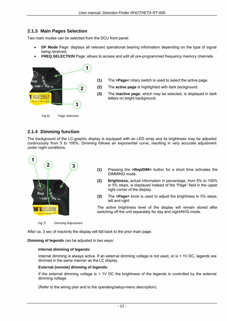
User manual Direction Finder RHOTHETA RT-600
- 11 -
213 Main Pages Selection
Two main modes can be selected from the DCU front panel
DF Mode Page displays all relevant operational bearing information depending on the type of signal being received
FREQ SELECTION Page allows to access and edit all pre-programmed frequency memory channels
Fig 6) Page Selection
(1) The gtPagelt rotary switch is used to select the active page
(2) The active page is highlighted with dark background
(3) The inactive page which may be selected is displayed in dark letters on bright background
214 Dimming function
The background of the LC-graphic display is equipped with an LED array and its brightness may be adjusted continuously from 5 to 100 Dimming follows an exponential curve resulting in very accurate adjustment under night conditions
Fig 7) Dimming Adjustment
(1) Pressing the gtRepDIMlt button for a short time activates the
DIMMING mode
(2) Brightness actual information in percentage from 5 to 100 in 5 steps is displayed instead of the ldquoPagerdquo field in the upper right corner of the display
(3) The gtPagelt knob is used to adjust the brightness in 5 steps left and right
The active brightness level of the display will remain stored after switching off the unit separately for day and nightNVG mode
After ca 3 sec of inactivity the display will fall back to the prior main page Dimming of legends can be adjusted in two ways
Internal dimming of legends
Internal dimming is always active If an external dimming voltage is not used or is lt 1V DC legends are dimmed in the same manner as the LC display
External (remote) dimming of legends
If the external dimming voltage is gt 1V DC the brightness of the legends is controlled by the external dimming voltage (Refer to the wiring plan and to the operatingsetup-menu description)
User manual Direction Finder RHOTHETA RT-600
- 12 -
215 Squelch Operation
The main challenge of operating a direction finder is trying to use only the signal transmitted by the target in order to calculate its bearing accurately because noise and RF disturbances will cause misleading bearing indications In order to prevent the direction finder to calculate bearing results which are due to noise and disturbances several techniques are available If a signal can be distinguished from noise or other signals by its message content (eg LoJack ID) only transmissions containing the required message content are used for bearing In other cases the squelch can be used to suppress unwanted weak signals and noise A squelch level called threshold has to be set by the user or automatically by the system All signals with strength below this threshold value will be ignored while signals with strength above this level will cause a bearing indication So for a signal to be usable for bearing calculation it has to be sufficiently stronger than noise or disturbing signals that the receiver can clearly distinguish between wanted and unwanted signals As a result of the squelch technique the receiver sensitivity is reduced to the level set by the squelch threshold decreasing the maximum distance or range to the transmitter However it might be desirable to obtain bearing information even for weak signals which are very close to the noise level In this case it will be necessary to reduce the squelch level below the noise level As soon as the modulation of a signal can be heard on the speaker it can be expected that bearing calculation is possible If the noise is randomly distributed ndash as with ldquowhite noiserdquo ndash and no other signal is received the bearing indication will also be random If the noise is not random but rather a specific disturbance the bearing indication will point to the source of the noise If there is a very weak signal ldquoburiedrdquo in the noise this signal will produce a correct bearing indication thanks to sophisticated bearing technologies used in the RT-600 system Fluctuations due to noise will be small even at low signal levels however the reaction time of the bearing indication can increase To verify if a bearing indication is due to white noise or to an internal disturbance source or if it is due to a valid signal the aircraft should make a slow turn If the bearing indication is due to an external signal eg a SAR beacon the bearing indication should compensate the changed relative flight angle Example with a bearing indication of 30deg The signal is hardly audible as it is buried in the noise The airplane makes a turn left by 60deg If the bearing indication is not changing to approximately 30deg+60deg = 90deg after a few seconds the bearing is likely to be due to noise or internal disturbances from the aircraft Note The weaker a signal is the longer it will take to change the bearing Durations around 5 seconds are not unfamiliar in such cases Therefore it is not useful to use this procedure for signals with short transmission times and low transmit duty cycles such as COSPAS-SARSAT transmission The procedure is best suited for ELT transmission with a continuous signal and still well-suited for ELTs with intermittent transmission (down to 33) In cases where pulsed signals are to be received the receiver is able to decide automatically which squelch level is best-suited for normal operation In such cases an automatic (ldquoArdquo) squelch is provided The threshold is automatically set to a value higher than the calculated noise level The difference in dB between noise and threshold level can be defined in the Setup Menu Refer to the chapter ldquoSetup Pagerdquo for details During AUTO squelch operation the user has the possibility to force the squelch into MANUAL mode but needs to be aware of the operational limitations described in this chapter In cases where the Antenna Unit checks signal validity autonomously and without useful possibilities of user interaction user interaction is not possible and the squelch purely follows internal rules appropriate to the type of signal received
User manual Direction Finder RHOTHETA RT-600
- 13 -
Examples of different squelch settings
Fig 8) Manual squelch mode correct squelch
adjustment
Correct squelch adjustment If the squelch is set to level (b) slightly over the noise level (a) the receiver audio output remains quiet and no wrong noisy bearing is indicated
Fig 9) Manual squelch mode Incorrect squelch
adjustment
Incorrect squelch adjustment If the squelch level is set (b) below the noise level (a) a wrong noisy bearing is indicated
Fig 10) Automatic squelch mode
Automatic squelch mode Automatic squelch mode is indicated by an ldquoArdquo (c) above the squelch level marker Depending on the SN-Ratio setting the squelch level is automatically set slightly higher than the noise level Using the SQL rotary switch (1) the user can change to manual squelch mode Automatic squelch mode can be activated again by setting the squelch level manually to lt 0 or gt 60
Fig 11) Automatic squelch mode with strong signal
Automatic squelch mode with strong signals Strong short receive signals will not modify the squelch level setting
Fig 12) Automatic squelch mode and not adjustable by
the user
Automatic squelch mode level not re-adjustable by user When the squelch is adjusted automatically by the system and the user is not allowed to change it an ldquoXrdquo (c) is displayed above the squelch level marker
User manual Direction Finder RHOTHETA RT-600
- 14 -
22 Frequency (FRQ) Selection Page The Frequency Selection (FRQ Selection) Page allows the user to select a frequency select a band and edit a frequency
Open FRQ Page
From the ldquoDFrdquo standard page activate the Page Rotary Switch in any direction to open the ldquoFRQrdquo Page for Frequency Selection
Fig 13) Open FRQ Page
Fig 14) FRQ ndash Frequency Selection Page
221 Selecting a Frequency
(1) Use the Page knob ldquoFRQrdquo again to select (recall) a frequency from
gtMEMlt four (4) memory channels gtWlt one (1) working (operating) frequency gtFIXlt fixed frequencies gtCPSARlt seven (7) COSPAS-SARSAT channel groups
(2) The actual adjusted frequency
(3) Frequency band-information
Exit Frequency dialogue
(4) Press push-button gtF1lt ldquoEXITrdquo to exit to DF mode (using the actual frequency
222 Recalling and editing frequencies from a memory channel
Recall
(1) With changing the Page rotary knob memory channels 1 4 can be selected The gtmarkerlt symbol indicates the actual memory channel
Edit
(2) MHz plusmn edits the MHz Value of the actual frequency
(3) kHz plusmn edits the kHz Value of the actual frequency
(4) F2 switches to next band
gtMHzlt and gtkHzlt directly changes and overwrites the actual selected memory frequency inside the actual band (see also 224 Editing a Frequency)
Fig 15) Recall frequency of Memory channel 3
User manual Direction Finder RHOTHETA RT-600
- 15 -
223 Recalling frequencies from fixed frequencies or CospasSarsat Channels
Fig 16) FRQ Selection Page with FIX1 selected
(1) ldquoFIXrdquo Selection range for fixed frequencies
for RT-600 Standard version for RT-600 Law Enforcement version
FIX1 ldquoEltPlbrdquo 121500 MHz international VHF air distress emergency frequency
FIX2 ldquoChnl16rdquo 156800 MHz marine VHF emergency radio channel 16
FIX3 ldquoEltMILrdquo 243000 MHz military UHF air distress emergency frequency
FIX1 ldquoEltPlbrdquo 121500 MHz international VHF air distress emergency frequency
FIX2 ldquoChnl16rdquo 156800 MHz marine VHF emergency radio channel 16
FIX3 ldquoLE(USA)rdquo 173xxx MHz LoJack Recovery System
FIX4 ldquoETSSTDrdquo 216487 MHz ETS standard frequency
FIX5 ldquoETSUCVrdquo 216512 MHz ETS ucover frequency
(2) ldquoCPSARrdquo Selection range for Cospas Sarsat channel groups
CPSAR1 ldquo022-028rdquo 406022 hellip 028 MHz Channel A B C
CPSAR2 ldquo031-037rdquo 406031 hellip 037 MHz Channel D E F
CPSAR3 ldquo040-043rdquo 406040 hellip 043 MHz Channel G H
CPSAR4 ldquo046-052rdquo 406046 hellip 052 MHz Channel I J K
CPSAR5 ldquo055-061rdquo 406055 hellip 061 MHz Channel L M N
CPSAR6 ldquo064-070rdquo 406064 hellip 070 MHz Channel O P Q
CPSAR7 ldquo073-076rdquo 406073 hellip 076 MHz Channel R S
User manual Direction Finder RHOTHETA RT-600
- 16 -
224 Editing a Frequency
While on the FRQ SELECTION Page the user can directly edit the frequency displayed
Fig 17) FRQ Selection Page before frequency editing
(1) gtMHzlt Rotary switch for direct adjustment of the displayed MHz range inside the actual band
(1 x step = 1 MHz adjustment)
(2) gtkHzlt Rotary switch for changing the displayed kHz frequency according to the actual band frequency grid (as example 8333 kHz at the VHF airband)
(3) gtF2lt Adjustment of the next available band (see next page gtgt Selecting a Frequency Band)
Fig 18) FRQ Selection Page after frequency editing
If the selected and marked frequency is not one of the MEM [14] channels then the changed frequency is automatically stored in the work frequency WorkFRQ channel
User manual Direction Finder RHOTHETA RT-600
- 17 -
225 Selecting a Frequency Band
While on the FRQ Selection Page each available band can be selected by pressing F2 BAND
(1) Press push button F2 BAND for
switch over to the next band
(2) Designation of actual selected band
(3) Max frequency limits of the actual selected band (depends on wide band options)
Fig 19) FRQ Selection Page (bands)
Frequency bands availability depends on the system version (A LE) and its wide band options (F1 to F4) These optional wide bands are available if ordered in addition to the default bands Here is a listing of DEFAULT and OPTIONAL bands available with each version of the system RT-600 (STANDARD) Listing of bands
Default bands available OPTIONAL extended bands available
Band designation Frequency limits Option Designation Frequency limits
VHF Emergency Band 118000 hellip 124000 MHz gt F1 VHF Air Band 118000 hellip 136992 MHz
VHF Marine Band 154000 hellip 163000 MHz gt F2 Extended VHF Marine 137000 hellip 224995 MHz
UHF Emergency Band 240000 hellip 246000 MHz gt F3 UHF Air Band 225000 hellip 399975 MHz
COSPAS SARSAT 400000 hellip 406092 MHz
UHF FM Band 406100 hellip 410000 MHz gt F4 Additional UHF FM 406100 hellip 470000 MHz
RT-600 (Law Enforcement) Listing of bands
Default bands available OPTIONAL extended bands available
Band designation Frequency limits Option Designation Frequency limits
VHF Emergency Band 118000 hellip 124000 MHz gt F1 VHF Air Band 118000 hellip 136992 MHz
VHF Marine Band 154000 hellip 163000 MHz gt F2 Extended VHF Marine 137000 hellip 163000 MHz
LoJack 164000 hellip 174000 MHz
ETS 216000 hellip 220000 MHz
COSPAS SARSAT 400000 hellip 406092 MHz
User manual Direction Finder RHOTHETA RT-600
- 18 -
23 Direction Finder (DF) Mode Direction Finder (DF) mode is generally used to display all valid information processed by the DF from the signal received from a target transmitter The amount and kind of information displayed by the DCU depends on the type and content of the signal received and processed by the DF Simple signals such as the analog sweep-tone modulation received from a SAR beacon (ELT PLB EPIRB PDD) on 121500 MHz allow displaying only basic bearing information while digital signals such as COSPAS-SARSAT and LOJACK allow displaying more information for ex beacon IDs GPS coordinates codes VLUs etc
231 Operating Elements in DF Mode
Fig 20) Operational Elements in DF Mode
This picture shows the DCU operating in DF Mode on the international emergency frequency 121500 MHz
with an active signal being received (1) gtFREQUENCYlt Rotary switch activates the ldquoFRQrdquo frequency page for changing and selecting the
active frequency The last selected frequency remains stored after switching offon the device The selected frequency is shown on the graphic display bottom right Above additional information for the selected frequency is displayed The use of the rotary switch activates a sub-page Please refer to the Frequency Selection section for details
(2) gtVOLUMElt Rotary switch to adjust the audio output level The volume of a linked external speaker or amplifier can be adjusted in a range from 0 (off) to 99 (maximum loudness) The selected volume is shown in the bottom left corner of the graphic display The volume remains stored after switching offon the device
(3) gtSquelch Levellt adjusts the squelch level The squelch level has to be above the receiving level without signal (noise) Only signals above the squelch level are audible in the loudspeaker and used by the direction finder for bearing indication The gtSQLlt rotary switch allows to select the squelch threshold ie a minimum signal strength of an incoming signal to be processed The current settings on a signal level scale from 0 to 60 is shown in bright letters on dark background below the SQL rotary switch and as an arrow beside the signal Strength Bar-Graph
(4) The gtCLRlt Push-button is used for erasing the internal bearing value averaging store and the Last Signal Timer To activate this function the push-button has to be hold down for a minimum of circa two seconds The sophisticated averaging store increases bearing precision and enables at all an usable
User manual Direction Finder RHOTHETA RT-600
- 19 -
bearing display in case of bad receiving signals (if there is a far away transmitter andor temporary complete loss of a receiving signal) Caused by the averaging procedure a drag error may occur which might be disturbing the bearing indication after a quick change of course of the aircraft or vehicle In this case the indicated bearing value lags by the real bearing value for about two seconds (for very weak signals even longer) By pressing this push-button after a quick change of course the display will show the new bearing value without drag error Additionally the F1CLR Push-Button is used to activate specific functions high-lighted in the menu below the button by pushing it for a short time (here as example ldquoSCANrdquo starts scanning the actual air band)
(5) gtSTORElt push-button Without function except if a special function is high-lighted in the menu line of the display
(6) gtREPEATlt Push-button when pressed and hold for min 3 sec the last valid bearing value with corresponding receiving level is displayed
232 Standard Display in DF Mode
Fig 21) DF Mode
(1) gtRelative Bearing valuelt by means of a sophisticated averaging procedure a steady display is
accomplished as graphic display and as text in the range of 0deghellip 359deg (0deg corresponds to bearing direct ahead)
(2) gtSpreadlt maximum deviation of un-averaged bearing values This is an indicator of bearing quality The wider the range between the directions of maximum deviation the worse the received signal is As a result of the excellent averaging procedure even with a spread of 45deg good bearing results are achieved
(3) gtReceiving levellt (field strength) of the signal as a relative percentage value visualized as bar-graph indication and as decimal value Even without a received signal a certain noise level may be displayed
(4) gtSquelch levellt (independently adjustable and stored for each frequency band) Squelch level is indicated as marker at the Signal Strength Bar-Graph or as direct relative level value A usable bearing analysis can only be achieved if the squelch level is above the noise level (without received signal) If the antenna unit is placed close a heavily disturbing electronic devices the squelch level has to be raised thus making the direction finder being less sensitive In receive modes where the squelch level is set automatically an ldquoArdquo above the marker indicates the ldquoAutosquelchrdquo functionality
(5) gtLast Signallt timer showing the time since a signal has been received for the last time (ie since a signal has been stronger than the squelch level) Values are ldquominutes secondsrdquo
User manual Direction Finder RHOTHETA RT-600
- 20 -
233 Special Options in COSPAS-SARSAT DF Mode
Especially for the use together with beacons transmitting a data signal according to COSPAS-SARSAT specifications in the 406-MHz-Band special functionalities and pages are being provided After selection of a COSPASSARSAT Frequency (Refer to the chapter ldquoFrequency selection Pagerdquo) the bearing page provides additional information and operating options
Fig 22) Operational Elements and Display in COSPAS-SARSAT DF Mode
(1) gtAuto Squelchlt indication indicating that the squelch level is set automatically to be close to the noise
floor It is recommended to always use the Auto Squelch during COSPAS-SARSAT operation This can be achieved by manually selecting 0 (lowest possible value) or 60 (highest possible value) as squelch level During COSPAS-SARSAT-Operation this will force the automatic setting of the level
(2) gt121500lt menu option The COSPAS-SARSAT signal in the 406 MHz band is transmitted only every 50 seconds in form of a short data burst of 440 or 520 ms approaching the transmitter it will be received earlier than the 121500 MHz continuous signal due to its high transmitter power However in a lower distance to a transmitter bearing on 121500 MHz is faster thanks to the continuous or rapidly intermittent signal The 121500 MHz menu option allows a direct switch-over to 121500 MHz Direct return back from 121500 to the COSPAS-SARSAT band is possible from the 121500 MHz bearing Window in COSPAS-SARSAT mode Please refer to the chapter ldquo121500 MHz bearing Window in COSPAS-SARSAT moderdquo for details
(3) gtDecodelt menu option allows to open the COSPASSARSAT Decode sub-page by shortly pushing the F2 push-button above the menu option
(4) gtFrequency rangelt indication COSPAS-SARSAT is using a channel spacing of 3 kHz for its beacons Due to the internal architecture of the direction finder it is possible to receive more than one channel in the same time Thus frequency steps of the direction finder are 833 kHz instead of 3 kHz The receive frequency covered by the current receive frequency setting is shown in the display line above the receive frequency indication
Important If the exact frequency of the COSPAS-SARSAT beacon is unknown it is strongly recommended to use the COSPAS-SARSAT scanning functionality in order to detect the correct frequency (Refer to the chapter ldquoFrequency selection Pagerdquo amp ldquoCOSPAS-SARSAT Scan Moderdquo)
User manual Direction Finder RHOTHETA RT-600
- 21 -
234 COSPAS-SARSAT Decode Window
The COSPAS-SARSAT Decode Window allows decoding incoming COSPAS-SARSAT data messages Only while this decode window is activated the decoding is possible An already received COSPAS-SARSAT puls while DF bearing mode was activated can not be used for decoding afterwards In this case the user has to wait while this decode window is active for the next transmitted puls approx 50 sec later
Fig 23) COSPAS-SARSAT Beacon Information Page
(1) gtExitlt push button (F1 button) allows to exit the decode window and switch back to the COSPAS-
SARSAT DF Mode page
(2) gtSARSATlt in the upper right corner of the display indicates that the COSPAS-SARSAT decode function is activated
(3) gtCountrylt displays the COSPAS-SARSAT Country Code coded into the received data message
(4) gtLast Signallt time since the last COSPAS-SARSAT message has been received in minutes secondsrsquo format
(5) gtPositionlt field showing in case of location protocols being used by the beacon the encoded GNSS position data (latitude longitude) transmitted by the beacon
(6) gt15-HEX-IDlt 15-HEX-ID of the beacon in hexadecimal format
(7) gtData stringlt of the bits 25 to 112 of the COSPAS-SARSAT data burst in case of short messages and bits 25 to 144 in case of a long message format The last 8 Hex Values are separated by a blank Bit- and Frame-synchronization hex values (Bits 1 to 24) are suppressed to increase the readability of the data message
(8) gtXlt sign to indicate that the Squelch is controlled by the antenna unit for optimum sensitivity The user has no access to the Squelch setting
User manual Direction Finder RHOTHETA RT-600
- 22 -
235 Tracking 121500 MHz while in COSPAS-SARSAT Mode
While in COSPAS-SARSAT DF Mode the user can switch to 121500 MHz in order to track the beacon in VHF If a valid signal is not received in 121500 MHz the user can switch back to the last active COSPAS-SARSAT channel (406 MHz frequency) being tracking previously
Fig 24) Tracking 121500 MHz while in COSPAS-SARSAT Mode
Differences are (1) gt406xlt press F1 to switch back to the last
COSPAS-SARSAT channel (406 MHz frequency) being tracking previously
(2) gt121500 MHzlt Actual frequency being tracked
User manual Direction Finder RHOTHETA RT-600
- 23 -
236 COSPAS-SARSAT Scan Mode
If the COSPAS-SARSAT Scan Mode has been selected at the frequency selection page ldquoFRQrdquo the COSPAS-SARSAT channels as selectable manually from the Frequency Selection Page are scanned After reception of a COSPAS-SARSAT Signal the scanning is stopped at the received frequency Due to the fast scanning ndash the complete COSPAS-SARSAT sub-band is scanned within less than 400 ms ndash detection of a receivable COSPAS-SARSAT signal is possible within one COSPAS-SARSAT repetition cycle
Fig 25) FRQ Selection Page with SCN COSPAS-SARSAT Scan Page selected
At the frequency selection page an active COSPAS SARSAT scanning can be stopped by de-activating it with the rotary button (1) While the scanning is active it is also possible by pressing gtF1lt ldquoEXITrdquo to switch back to the DF pagehellip
Fig 26) DF page with active COSPAS-SARSAT Scan Mode at the DF page
(1) gtSCANlt flashing indication notifying the user that the equipment is operating in scan mode
(2) Frequency display indicating the COSPAS-SARSAT scanning frequency range
(3) gtXlt sign showing that squelch settings are controlled autonomously by the receiver
Scan mode can be left by pressing gtF1lt ldquoSTOPrdquo
User manual Direction Finder RHOTHETA RT-600
- 24 -
237 Marine Ship Scan Mode
Fig 27) DF Mode FRQ = 156800 MHz F1 for scan function
If the active frequency (2) is within the VHF Marine Band a fast scan of all ship channels is possible by pushing gtF1lt ldquoSCAN (1) In this scanning mode all marine channels 1 to 88 (156025 to 157450 MHz) are scanned continuously until a signal is received To offer the best monitoring functionality for the user also signals between to channels (4) are detected (scanning without gap) In order to prevent the scan to stop on noisy frequencies it is recommended to start scanning with high squelch settings You can reduce the squelch level in steps until the scan stops on a noisy frequency for the first time Then increase the squelch level slightly This will result in the highest possible scan sensitivity and avoiding noisy channels due to RF disturbances sometimes generated by other equipment in own aircraft
Fig 28) DF Mode active scanning in process
The scanning is stopped by pressing gtF1lt ldquoSTOPrdquo (3)
User manual Direction Finder RHOTHETA RT-600
- 25 -
24 Law Enforcement Operation Law enforcement special ops and other organizations use the RT-600 LE (LAW ENFORCEMENT) version instead of the RT-600 A (STANDARD) version One of the reasons is that the LE version features scanning and tracking of signals like LoJack and ETS as well as signals in the 216000 MHz ndash 220000 MHz band such as medical beacons wristankle transmitters cashasset recovery ldquotagsrdquo etc However the LE version shares many functions in common with the A version such as scanning and tracking in the AIR band COSPAS-SARSAT band etc
241 Power-On procedure
The power-on procedure is the same as described in 211
(1) System Version ldquo(L)rdquo for LAW ENFORCEMENT version
Fig 29) STARTUP Screen (see 211 for details)
242 LoJack Scan Mode Start scanning for a VLU Code
For the convenience of Law Enforcement and other special ops users who frequently engage in tracking SVRS (Stolen Vehicle Recovery System) signals such as LoJack (LoJack Corp FCC 9020 Part 2 SVRS) RHOTHETA has optimized the power-on procedure of the RT-600 LE version so that right after the STARTUP screen the unit displays automatically the LoJack Scan Mode page to start immediately scanning for a valid VLU (Vehicle Location Unit) code without pressing any key
Fig 30) LoJack Scan Mode unit is scanning for a LoJack VLU Code
(1) gtscan LoJacklt DF is scanning for any new LoJack VLU Code
(2) gtEXITlt press F1 to exit and switch directly to DF Mode
User manual Direction Finder RHOTHETA RT-600
- 26 -
243 LoJack Scan Mode from any other page
While operating on any page other than the LoJack Scan page the user can switch directly to LoJack Scan Mode by pressing Hotkey F2 for 2 secs
(1) press Hotkey F2 for 2 secs to switch to the LoJack Scan page
Fig 31) Hotkey F2
User manual Direction Finder RHOTHETA RT-600
- 27 -
244 Manual activation of LoJack Scan Mode
(1) select the LoJack frequency (see also Frequency Selection Page)
(2) press F1 to switch back to the DF MODE
Fig 32) FRQ Selection Page FRQ = LoJack BAND = LoJack (164-174 MHz)
While in DF MODE with adjusted LoJack frequency the user can switch directly to the LoJack Scan by pressing gtF1lt ldquoSCANrdquo
(1) press F1 SCAN to switch to the LoJack Scan page
(2) still no LoJack ID filter used (ID=off) all transmissions are received on the active frequency as example also unwanted tower pulses
Fig 33) DF Mode with LoJack filter OFF
User manual Direction Finder RHOTHETA RT-600
- 28 -
245 Receiving and accepting a new VLU Code
While in LoJack Scan Mode waiting for a VLU Code if a new VLU Code is displayed the user can accept it and switch directly to DF Mode by pressing F2
(1) a new LoJack VLU Code (0001A) has been received
(2) press F2 to accept the new VLU Code (0001A) and switch to DF MODE page with the LoJack filter activated to track only 0001A
Fig 34) LoJack Scan Mode with new VLU Code received
246 Entering a new VLU Code manually
While in LoJack Scan Mode the user can enter a LoJack VLU code also manually
(1 2 3) use the SELECTplusmn and plusmnVALUE knobs to enter a new LoJack VLU Code active ID (0001A)
(4) Press F1 to accept the new VLU Code and switch to DF Mode with the LoJack filter ON to track only 0001A
Fig 35) LoJack Scan Mode with new VLU Code entered manually
User manual Direction Finder RHOTHETA RT-600
- 29 -
247 Tracking one VLU Code while monitoring new VLU Codes
While on DF Mode and tracking a VLU Code (0001A) the user can turn the LoJack switch OFF with F2 also the user can start scanning all VLUs again with F1
0001A is displayed as the active VLU Code filter function is ON only 0001A is tracked
Monitoring of other VLU Codes is active in the background
(1) Press F1 to switch to the LoJack Scan Mode to scan for new VLU Codes
(2) Press F2 to switch LoJack filter OFF
Fig 36) DF Mode with active VLU Code and LoJack filter ON
248 Tracking one VLU Code and receiving a new VLU Code
While on DF MODE page and tracking VLU Code (0001A) in the background a new VLU Code is received and decoded (G2HC7)
(1) The new VLU Code is announced (NEW G2HC7)
(2) Press F1 to switch to LoJack Scan Mode to see the arrival time of G2HC7 and the possibility to change bearing to this new G2HC7
Fig 37) DF Mode with active VLU Code and announcement of new VLU Code
User manual Direction Finder RHOTHETA RT-600
- 30 -
249 Switching to a new VLU Code
While on the LoJack Scan Page tracking one VLU Code (0001A) and notified of a new VLU Code (G2HC7)
(1) press F1 to continue tracking 0001A
(2) press F2 to start tracking G2HC7
(3) Time elapsed since G2HC7 was last received
(4) Time elapsed since 0001A was last received
If F1 is pressed for 2 sec the indicated VLU Code (G2HC7) and ID (0001A) are deleted
Fig 38) LoJack Scan Page with one active VLU Code and one new VLU Code
2410 ldquoBlockingrdquo function of one LoJack VLU Code
The LoJack scan page can also be used to ldquoblockrdquo one unwanted LoJack VLU ID signal by separating the adjusted active ID from any other received LoJack VLU signal This is done by muting the audio (see example below) when a LoJack signal with VLU code ldquo0001Ardquo is received gtgt Any new VLU Code (active LoJack signal) - except for 0001A ndash will be displayed on the top row and generate the audible beep tone
Fig 39) LoJack Scan Page with one active VLU Code and audio OFF
Tip ldquoBlockingrdquo is an important tool for practical missions As example a stolen vehicle with VLU ID ldquo0001Ardquo was tracked in the DF bearing mode The mission
is completed but the VLU is normally still transmitting With the settings above only new VLU signals except the now unwanted ldquo0001Ardquo are audible and displayed in the upper (scan LoJack hellip for new VLU) box
User manual Direction Finder RHOTHETA RT-600
- 31 -
2411 Tracking in the 216 to 220 MHz band
The RT-600 features scanning and bearing functionality in the 216000 MHz to 220000 MHz band The 216000 MHz ndash 220000 MHz band contains frequencies and signals used by special services and tracked by law enforcement special ops and similar organizations These are some of the frequencies and services in this band
CFR 90259 tx 216000 MHz to 220000 MHz
Low Power Radio Service (LPRS) tx 216000 MHz to 217000 MHz
Medical beacons Project Lifesaver tx wristankle tx 213000 MHz to 216000 MHz
ETS tx stolen cashasset recovery tx ldquobaitrdquordquotagrdquo tx 216000 MHz to 220000 MHz tx = transmitter(s) However any future or current user of the Rhotheta RT-600 must be aware that tracking signals on the frequencies listed above may be challenging and even frustrating due mostly to negative factors in some of the transmitters
bull Very low RF power output
bull Inefficient antennas
bull Battery-powered devices with a ldquolow batteryrdquo condition
bull Devices worn or located in conditions of poor RF propagation
bull Devices with channel spacing different than the one specified for the RT-600
These factors can make it very difficult for the DF to receive the signal andor display an accurate bearing Disclaimer For the reasons explained above and even though the RT-600 features top performance in its class RHOTHETA does not offer - and is not to be held responsible for - any guaranteed minimum range or distance to a transmitter in this band
25 Setup Edit Page System settings are displayed in the setup page The functions described in this section should be used by trained personal only
Fig 40) Accessing the Setup Page
The setup page can be accessed by holding down the gtCLRlt (1) and gtREPlt (2) buttons simultaneously and in the same time performing a left-hand turn on the gtPagelt rotary switch (3)
User manual Direction Finder RHOTHETA RT-600
- 32 -
Fig 41) Setup Page
(1) gtStorelt push-button must be pressed in parallel if a value of a setting shall be modified If a value can
be modified the background stops to blink
(2) gtSelectlt rotary switch used to scroll through the menu options The value of the actually activated menu option is high-lighted with dark background and blinking
(3) gtValuelt rotary switch used to change values in menu options (gtStorelt (1) has to be pressed in parallel if a value shall be modified)
(4) gtSN-Ratiolt menu option representing the necessary Signal-To-Noise-Ratio (Difference between signal and noise level) used as criterion for the automatic squelch function Please refer to the chapter ldquoSquelch Operationrdquo for details Default value is 60 dB
(5) gtMounting Positionlt menu option to select Top- or Bottom-Mounting of the DF antenna In case of rooftop installation (eg on land vehicles) ldquoToprdquo shall be selected In case of bottom-down (upside-down) installation (eg on a helicopter) ldquoBotrdquo shall be selected If this option is not selected correctly all bearing values will be mirror-inverted
(6) gtBearing Offsetlt menu option to include a constant offset correction to the bearing indication Bearing values in degrees will be changed according to the offset value
(7) gtMaximum External Dimming Voltage for Legendslt menu option which sets the upper limit of the dimming input voltage for the legends-panel Range=[15 hellip 28]V
(8) gtMinimum External Dimming Voltage for Legendslt menu option which sets the lower limit of the dimming input voltage for the legends-panel Range=[15 hellip 28]V
(9) gtPagelt rotary switch to be turned right-hand to go back to the Direction Finder page A left-hand turn on this rotary switch will show up an additional service page with debug information used for system checks
(10) gtExtended Seriallt It is possible to enable or disable the extended serial data protocol Only of interest if serial data is used by any connected control units like moving maps or computers For detailed information see (Serial interface data protocol (short description)gt at page 46) If there are compatibility problems with already existing older remote control software it is recommended to switch OFF the extended serial data protocol
User manual Direction Finder RHOTHETA RT-600
- 33 -
3 Error messages If an internal error of the device is recognized a corresponding flashing error message will be shown in the DF pages
Fig 42) Error Messages
(1) Error message including error code (in brackets)
(2) Short description of the indicated error
In case of coincidence of various errors the error with the highest priority will be displayed
Error message Error location Reason
Error (12) VOLTDU
Main voltage supply Main Voltage input too low ( 100 V)
Error (11) NO AU
Connection antenna display or Antenna Unit
No serial data (RS485) from Antenna Unit No or damaged connection between antenna and display or damaged antenna unit
Error (10) BAD AU
Connection antenna display
Incompatibility or bad data connection between display and antenna
Error (9) BAD RU
Remote Unit Incompatibility or bad data connection between display and external serial Remote Unit or PC
Error (8) VOLTAU
Antenna Unit Voltage supply at Antenna Unit too low ( 90 V) Main voltage supply too low or considerable drop of voltage between display and antenna
Error (7) BAD DCU
Connection Display Antenna
Incompatibility or bad data connection between antenna and display
Error (6) NO DCU
Connection Display Antenna
No serial data from Display Control Unit to Antenna Unit
Error (5) PLL ERR
antenna Error in synthesizer-oscillator of receiver in Antenna Unit
Error (4) FRQ+OFS
received transmitter Received frequency too high (more than 6 KHz error of transmitter)
Error (3) FRQ-OFS
received transmitter received frequency too low (more than 6 KHZ error of transmitter)
Error (2) DECODE
radio distance transmitter DF
Data Bits of decoded signal (COSPAS-SARSAT or LoJack) defective
Error (1) DATARNG
Incompatibility of data DCU AU
Protocol data bytes out of valid range
Error (0) NO REC
Antenna Unit receiver
Receiver board defective
User manual Direction Finder RHOTHETA RT-600
- 34 -
4 Installation
41 Antenna unit A convenient position of the monopole bearing antenna is crucial for good bearing results The antenna needs an effective ground connection to the body of the aircraft or to the roof of the vehicle If there is no metallic mounting surface available a metallic sheet or similar (net) with connection to ground has to be applied first between vehicle-body and antenna In this hatched area the antenna touches the body ofthe vehicleaircraft In order to obtain a good groundconnection the surface of the body should be bared(Measuring unit [mm])
8 x holes for mounting the antenna unit to the
vehicle aircraft
Fig 43) Antenna Mounting Drawing
User manual Direction Finder RHOTHETA RT-600
- 35 -
411 Influence of antenna location and environment on the bearing accuracy
Recommendations concerning the practical antenna unit location on helicopters and airplanes
The bearing accuracy of the direction finder antenna unit is severely influenced (comparable to an airspeed sensor) by the environment For comparison a perfect high quality speed sensor will not indicate the true airspeed if this sensor is interfered by strong turbulences The direction finder antenna unit acts as a sensor for electromagnetic waves In the near field of this antenna unit any conductive (eg metallic) obstacle will influence the incoming wave field and create reflections which decrease the bearing accuracy These are general physical limitations concerning all types of direction finder systems To achieve the best bearing results it should be considered that the antenna unit is installed as far away as possible from any other vertically polarized conductive structure If possible there should be no reflectors within an area of 2-3 feet around the antenna unit In this worst case example the direction finder will not work properly
Fig 44) Antenna Installed in a Bad Location
In this example the antenna unit is located too close to the cable cutter of the helicopter This cutter will produce strong reflections especially as the length is equal to Lambda4 within the VHF airband
User manual Direction Finder RHOTHETA RT-600
- 36 -
Examples of properly installed direction finder antenna units
Fig 45) Antenna Installed in Good Locations
User manual Direction Finder RHOTHETA RT-600
- 37 -
42 Display and Control Unit
The display control unit may be mounted into a front panel by the means of this mounting drawing
Fig 46) DCU Mounting Drawing
(all dimensions in [mm]) To install or uninstall the display control unit perform the following steps (1) Remove the cover caps of the four rotary switches
(2) Loose the screws visible below the position of the cover caps
(3) Remove the plastic button from the axis of the four rotary switches
(4) Mount dismount the display control unit
(5) Re-install the plastic buttons on the axis of the four rotary switches
(6) Fix the screws so that the plastic buttons are fixed on the axis
(7) Re-install the cover caps on the four rotary switches
User manual Direction Finder RHOTHETA RT-600
- 38 -
43 System Interconnect Wiring Diagram (Also refer to chapter ldquoTechnical Datardquo for details)
Fig 47) System Interconnect Wiring Diagram
6-pol Amphenol plug femalePTG06SE10-6S(SQ)
max length of cable 20 m 9-pol Sub-D plug (femalemale)
User manual Direction Finder RHOTHETA RT-600
- 39 -
5 Technical Data
51 Electric features
Method of bearing Doppler-principle (3 kHz rotational frequency right left rotation)
Bearing accuracy1 plusmn 5deg RMS
Internal resolution 1deg
Bearing Sensitivity VHF AirEmergency le 25 μVm (typical)
VHF Marine le 25 μVm (typical)
UHF Emergency and ETS le 4 μVm (typical)
COSPAS-SARSAT le 4 μVm (typical)
LoJack Decoding (50 Message Error Rate) and bearing le 5 μVm (typical)
Frequency stability plusmn 20 ppm (Δff = plusmn210-6)
Reception frequencies
SAR version (Standard)
Frequency Options
VHF Emergency Band 118000 to 124000 MHz (833 kHz steps AM)
VHF Marine Band 154000 to 163000 MHz ( 500 kHz steps FM) (channel 16 selectable via channel no)
UHF Emergency Band 240000 to 246000 MHz (2500 kHz steps AM)
UHF FM Band 406100 to 410000 MHz ( 500 kHz steps FM)
COSPAS-SARSAT 400000 to 406092 MHz Including 406022 to 406076 MHz (Channel A S)
F1 VHF Air Band 118000 to 136992 MHz
F2 extended VHF Marine Band 137000 to 224995 MHz
F3 extended UHF Air Band 225000 to 399975 MHz
F4 additional UHF FM Band 406100 to 470000 MHz
Reception frequencies
LAW Enforcement version
Frequency Options
VHF Emergency Band 118000 to 124000 MHz (833 kHz steps AM)
VHF Marine Band 154000 to 163000 MHz (500 kHz steps FM) (channel 16 selectable via channel no)
LoJack 164000 to 174000 MHz (125 kHz steps FM)
ETS 216000 to 220000 MHz (10125 kHz AM)
COSPAS-SARSAT 400000 to 406092 MHz Including 406022 to 406076 MHz (Channel A S)
F1VHF Air Band 118000 to 136992 MHz
F2 extended VHF Marine Band 137000 to 163000 MHz
COSPAS-SARSAT fast scan mode
Full automatic detection of any active COSPAS-SARSAT channel A to S within 400 ms
COSPAS-SARSAT decoding
Reception and decoding of COSPAS-SARSAT data signal (112 or 144 bit) specified according to COSPAS-SARSAT
LoJack decoding Selectable LoJack ID display and selective active filtering
Special scanning modes
complete maritime ship band scanning within 3 s (channel 01 hellip 88 also frequencies between 2 channels are included)
1With undisturbed wave field and sufficient field strength Measuring by changing the angle of incidence with the antenna rotating on a revolving table in order to eliminate environmental influences on the results No modulation
User manual Direction Finder RHOTHETA RT-600
- 40 -
Bearable modulation A3E F3E A3X (ELT-modulation) F1D G2D COSPAS-SARSAT Bearing largely independent of modulation
Polarization Vertical
Polarization error 5deg at 60deg field vector rotation
Garbling cone Ca 30deg to the vertical
Time of response2 50 ms (with sufficient reception field strength)
LC-graphic display 128 x 64 pixels supertwist transflective extended range of temperature dark-blue display on yellow-green background background light Freely adjustable (exponential) dimming of brightness
NVG cockpit design Fully compatible NVIS Green B display Control Unit optional
Operating voltage 275 V nominal 12 V to 35 V DC
Current consumption LCD-background light Off max 500 mA (12 V DC) max 250 mA (24 V DC)
LCD-background light 100 max 750 mA (12 V DC) max 350 mA (24 V DC)
LCD-background light 100 max 900 mA (12 V DC) with NVG Option max 400 mA (24 V DC)
Audio out For external speaker approx 2 W (4 Ω)
Serial data interface Serial interface RS-232 (9600 baud 8 data bits 1 stop bit no parity)
2Very weak signals can considerably increase the time of response
User manual Direction Finder RHOTHETA RT-600
- 41 -
52 Interface External connections (optional at Sub-D 9-pol Male connector)
Dimming
Pin 8
external voltage input for variable dimming of legends
(optional)
Analog input signal for variable control of the legends illumination Input voltage range is freely adjustable in the range of 15 hellip 28 V in the setup menu Refer to chapter ldquoSetup Pagerdquo Default setting 8 hellip28 V (8 V = Off 28 V = max dimming for legends)
Input Impedance gt 50 k
Pin 6 night status line for LCD
dimming (optional)
Low-active (as example switch to ground) At input voltage lt 25 VDC the LCD dimming operates in nightNVG mode Maximum brightness ca 4 of daydefault mode brightness
Input Impedance gt 50 k
Pin 4 NVG status line for LCD
dimming (optional)
Low-active (as example switch to ground) At input voltage lt 25 VDC the LCD dimming operates in nightNVG mode Maximum brightness ca 4 of daydefault mode brightness
Input Impedance gt 50 k
AudioLF
Pin 7 Audio output signal
AC coupled voltage source with very low inner resistance Maximum output voltage ca 8 VPP = 283V RMS at maximum Volume Maximum output power ca 2 W with 4 speaker
If a headphone is connected ([32hellip600] 100mW) we recommend using a resistor (18 025 W) between audio output and headphone to prevent damage of the headphone
Serial interface RS232 (9600 baud 8 data bits 1 stop bit no parity)
Pin 3 TXD Serial output (ca plusmn10 V)
Pin 2 RXD Serial input (ca plusmn10 V)
User manual Direction Finder RHOTHETA RT-600
- 42 -
53 Mechanical features
Temperature range
Display Control Unit permissible operating temperature3 -20 degC +60 degC permissible storage temperature -30 degC +80 degC
Antenna Unit permissible operating temperature3 -40 degC +60 degC permissible storage temperature -55 degC +80 degC
Protective system Antenna Unit IP 67
Weights Display Control Unit 250 g Antenna Unit 2000 g
Dimensions Display Control Unit 82 mm x 82 mm x 43 mm (width x height x depth) Antenna Unit 270 mm x 185 mm
Fig 48) DCU Mechanical Drawing (all dimensions in [mm])
3 For temperatures lower than ndash10deg C a warm-up period of 15 min should be allowed
User manual Direction Finder RHOTHETA RT-600
- 43 -
Fig 49) AU Mechanical Drawing (all dimensions in [mm])
User manual Direction Finder RHOTHETA RT-600
- 44 -
6 Appendix
61 Frequency Ranges
User manual Direction Finder RHOTHETA RT-600
- 45 -
62 Frequencies of channels on maritime band (only for standard [A] version) Frequency-range of the RT-600 in the maritime band 156000 MHz 162025 MHz
Channel No frequency (ship - station) Frequency (coast - station)
1 156050 MHz 160650 MHz 2 156100 MHz 160700 MHz 3 156150 MHz 160750 MHz 4 156200 MHz 160800 MHz 5 156250 MHz 160850 MHz 6 156300 MHz 160900 MHz 7 156350 MHz 160950 MHz 8 156400 MHz 9 156450 MHz
10 156500 MHz 11 156550 MHz 12 156600 MHz 13 156650 MHz 14 156700 MHz 15 156750 MHz 16 156800 MHz 17 156850 MHz 18 156900 MHz 161500 MHz 19 156950 MHz 161550 MHz 20 157000 MHz 161600 MHz 21 157050 MHz 161650 MHz 22 157100 MHz 161700 MHz 23 157150 MHz 161750 MHz 24 157200 MHz 161800 MHz 25 157250 MHz 161850 MHz 26 157300 MHz 161900 MHz 27 157350 MHz 161950 MHz 28 157400 MHz 162000 MHz 60 156025 MHz 160625 MHz 61 156075 MHz 160675 MHz 62 156125 MHz 160725 MHz 63 156175 MHz 160775 MHz 64 156225 MHz 160825 MHz 65 156275 MHz 160875 MHz 66 156325 MHz 160925 MHz 67 156375 MHz 68 156425 MHz 69 156475 MHz 70 156525 MHz 71 156575 MHz 72 156625 MHz 73 156675 MHz 74 156725 MHz 75 156775 MHz 76 156825 MHz 77 156875 MHz 78 156925 MHz 161525 MHz 79 156975 MHz 161575 MHz 80 157025 MHz 161625 MHz 81 157075 MHz 161675 MHz 82 157125 MHz 161725 MHz 83 157175 MHz 161775 MHz 84 157225 MHz 161825 MHz 85 157275 MHz 161875 MHz 86 157325 MHz 161925 MHz 87 157375 MHz 161975 MHz 88 157425 MHz 162025 MHz
User manual Direction Finder RHOTHETA RT-600
- 46 -
63 Serial interface data protocol (short description)
631 General
Interface parameters RS232 9600 Baud 8 databits 1 stopbit no parity LSB sent first Timing of serial data For accurate use of the serial data (even for the optional serial input commands) the correct timing is mandatory The DCU (Display Control Unit) sends out via the RS-232 Pins (see 43 System Interconnect Wiring Diagram page 38) cyclic and autonomous every approx 250300 ms a binary data stream which contains all relevant DF-bearing information The output data contains one or two blocks of binary data (see next picture with accordingly description) The optional serial input is only used if changes (as example frequency change) are done by additional remote control units
Fig 50) Timing of serial data
Serial standard output
This output data is always available and contains all relevant DF-bearing data For detailed content see page 47
Optional extended serial output
This data contains some additional information like as example CospasSarsat or LoJack decoding and ID data For detailed content see page 50 The data is only available with DCU Software [Rev ge 320] and if this optional data block is configured as ON = enabled (see Setup Edit Page point (10) )
Even to avoid compatibility problems with already existing older remote control software it is possible to disable switch off this additional data block (see Setup Edit Page point (10) )
Optional serial input
Only used for optional commands to control DCU parameters If as example the direction finder frequency is changed remotely there is send to the DCU one time this data block with the new frequency For detailed content see page 52
User manual Direction Finder RHOTHETA RT-600
- 47 -
632 Serial standard output (protocol description)
Specification serial standard output
The binary data stream with a length of 39 bytes starts with a header byte (value = hex 0xA0 as ID for DF Mode) The next bytes contain different values for status bearing information and also service The last byte is used for data stream checksum control Remark This is a binary data protocol So every byte value from 0dec hellip 255dec (0x00 hellip 0xFF) is possible Because of this it is not allowed to realize a start byte detection by the content (0xA0) The idle line detection is recommended for detection the end of message Register of databytes (for details see next page)
byte no
[0] Header = 0xA0 Id for DF Mode
[1] Number = 39 = bytes in the complete message (including header and checksumbyte)
[2] Status (1) HSB [x|x|x|x|x|x|x|x] LSB | | | | | | | --gt (0) Receiving | | | | | | ----gt (1) Squelch controlled by AU (X) | | | | | ------gt (2) Permission RL Calibration | | | | --------gt (3) Line Night | | | ----------gt (4) Line NVG | | ------------gt (5) Dimming External | --------------gt (6) Autosquelch Active ----------------gt (7) 0=Standard Version 1=LE Version
[3] Status (2) HSB [x|x|x|x|x|x|x|x] LSB | ----------------gt (7) 0=Standard 1=extended serial dataprotocol = ONactive
[45] Error (Bits[120])
[6] Actual DCU Page
[7] Volume [0hellip100]
[811] Frequency [Hz]
[12] Active Band
[13] Actual Squelchlevel [0hellip60]
[14] Audio-Line amp_NF_Test Output
[15] (Not used)
[1617] Voltage_DCU ([0hellip335]=[0 hellip 335]V
[1819] Voltage_AU ([0hellip255]=[0 hellip 255]V
[20] Temperature_AU [-68hellip+127]degC
[21] Frequency Offset [-99hellip+99]
[2225] ServiceTest values (mode dependent test values for service only)
26 (Not used reserved)
[27] Level [0hellip100]
[2829] Bearing Averaged [0hellip359]deg relative
[3031] Bearing Live_Min [0hellip359]deg relative
[3233] Bearing Live_Max [0hellip359]deg relative
[34] Test Value PS-RAM Right Rotation[0hellip178] (for service only)
[35] Test Value PS-RAM Left Rotation [0hellip178] (for service only)
[3637] (Not used reserved)
[38] Checksum is the 2rsquos complement of the modulo-256 sum of all bytes without checksum-byte [0n-1]
User manual Direction Finder RHOTHETA RT-600
- 48 -
Detailed Description of important values for practical use
Status byte [2] Receiving Bit 0 of this value (LSB) indicates signal receiving Bit 0 = 0 then no signal is received and so on no bearing is available Bit 0 = 1 then bearing is possible Bit 1 if(1) then Squelch is controlled by AU (active at modes CospasSarsat Decode CospasSarsat Scanning LoJack with Filter=ID only)
Error bytes [4hellip5] 16 bit value each set bit corresponds to the error no (Refer to the chapter Error messages) Example - 0x0000 No error - 0x0800 Bit No 11 Set ( = No AU Error)
Actual DCU Page byte [6] indicates actual operating mode of DCU 0 = Standard bearing page 1 = Frequency memory page 2 = CospasSarsat decoding page 3 = LoJack decoding page (ID edit)
Frequency bytes [8hellip11] 32 bit value actual adjusted frequency [Hz] Example - 0x073DF160 1215000000 121500 MHz
Active Band Standard Version [A] 0=VHF Airband 1=VHF Marineband sea 2=VHF Marineband coast 3=UHV Airband 4=CospasSarsat LE Version [L] 0=VHF Airband 1=LoJack 2=Lifesaver 3=ETS 4=CospasSarsat
Actual Squelchlevel byte [13] Range [0hellip60] without signal the actual squelchlevel should always be adjusted a little bit over the noise level (Refer to the chapter Squelch operation)
Level byte [27] Range [099] actual receiving level (without signal this value is equal to the noise level) If a signal is received then this value corresponds to the signal strength of this signal
Relative Bearing averaged byte [2829] 16 bit value Range [0hellip359 0xFFFF] if the value = 0xFFFF then no valid bearing is available otherwise this value contains the actual averaged bearing information in Deg [0deg359deg] Example - 0X0114 276deg bearing (= left side oriented to heading)
Bearing Live MinMax byte[3031] amp [3233] - 16 bit values Range [0hellip359 0xFFFF] Only for signal quality or additional information ndash NOT recommended for bearing indication The relative live bearing field contains the maxmin bearing in degrees without averaging The relative live bearing reacts faster than the normal relative bearing but it has not the precision of the averaged bearing The MinMax Bearing Values are calculated within a time period of approx 250 ms If they are very close together (for example ldquo124rdquo and ldquo128rdquo degrees) then the signal quality is quite good A wide span of the minmax values (for example ldquo97rdquo and ldquo162rdquo) shows very noisy but nevertheless bearable signal quality
User manual Direction Finder RHOTHETA RT-600
- 49 -
633 DCU Info output (protocol description)
Specification DCU Info output
Remark This protocol is only available while the SetupEdit page is activated at the DCU
byte no
[0] Header = 0xAF Id for DCU Info Mode
[1] Number = 39 = bytes in the complete message (including header and checksumbyte)
[2]
(see standard output) [3]
[45]
[621] Info String of 15 byteschars the string contains Information about Unit Variant Software Version and Serial No
Example Byte [318] =
|--AU ID---||Var-||---Software Version---| |-------------- Serial No---------------| [0x44][0x55][0x41][0x33][0x2E][0x33][0x30][0x3A][0x20][0x20][0x30][0x31][0x32][0x33][0x34][0x00] rsquoDrsquo rsquoUrsquo rsquoArsquo rsquo3rsquo rsquorsquo rsquo3rsquo rsquo0rsquo rsquorsquo rsquo rsquo rsquo rsquo rsquo0rsquo rsquo1rsquo rsquo2rsquo rsquo3rsquo rsquo4rsquo rsquoENDrsquo | | | | __________________ | | ________________________ | n n n | | n n n n n | (Software Version) | | (Serial No) | gt rsquoArsquo = Standard Variant gt rsquoLrsquo = Law Enforcement Variant
User manual Direction Finder RHOTHETA RT-600
- 50 -
634 Optional extended serial output (protocol description)
The data content depends on the actual mode of the direction finder To get special data the direction finder has first to be switched to the equivalent mode
COSPAS-SARSAT Decoding data
This data is only available and valid if Display Control Unit with actual software Rev ge 320 (see Power-On procedure page 10) Configuration of Extended serial = ON (see Setup Edit Page point (10) ) Direction Finder COSPAS-SARSAT decoding mode is activated by selecting the corresponding page
(see COSPAS-SARSAT Decode Window page 20 and page 21) and so on Header (byte 0 of data) = 0x91
A valid COSPAS-SARSAT decoding data protocol is always marked by the first data byte (header = 0x91) Always after receiving and decoding of a valid COSPAS-SARSAT pulse the complete data protocol with 33 bytes is send out one time
Byte No
[0] Header = 0x91 (Identification for CPSarsat decoding mode)
[1] Number of bytes - 7 if no decoded pulse is available - 33 if new pulse was received and is available
[2] Error
[3] Bit[0] - 0 =gt No new 406 MSG (decoded data) available - 1 =gt New valid 406 MSG available (Sync amp Frame Ok) Check Error Status for Bit-Errors
Bit[61] AutoSquelch Level valid range [060] ( decimal)
Bit[7] = 1 Squelch controlled by AU
[4] Signallevel of received signal valid range [099] ( decimal)
[5] Voltage of Antenna Unit Power Supply input valid range [80255] (decimal = 80 255 V DC)
[6] Temperature inside Antenna Unit valid range [-50+100] (degC signed byte value)
The following databytes are only available if a correct CPSarsat puls gets received and decoded with correct checksum
[724] 18 x Databytes complete orginal CPSarsat 406 decoded message (144 bit)
Databyte Nr [ Byte 7 ] [ Byte 8 ] [Byte9 Byte24] 406 MSG Bit Nr [1 2 3 4 5 6 7 8] [9 10 11 12 13 14 15 16] [17 144]
[25] SN-Flag valid values 0x53=rsquoSrsquo 0x4E=rsquoNrsquo 0x2D=rsquo-rsquo if no GPS data available
GPS-Position Latitude
[26] Deg valid values [090] (decimal Deg) 0xFF if no GPS data available
[27] Min valid values [059] (decimal Deg) 0xFF if no GPS data available
[28] Sec valid values [059] (decimal Deg) 0xFF if no GPS data available
[29] WE-Flag valid values 0x57=rsquoWrsquo 0x45=rsquoErsquo 0x2D=rsquo-rsquo if no GPS data available
GPS-Position Longitude
[30] Deg valid values [0180] (decimal Deg) 0xFF if no GPS data available
[31] Min valid values [059] (decimal Deg) 0xFF if no GPS data available
[32] Sec valid values [059] (decimal Deg) 0xFF if no GPS data available
User manual Direction Finder RHOTHETA RT-600
- 51 -
LoJack ID data
This data is only available and valid if Display Control Unit with actual software Rev ge 320 (see Power-On procedure page 10) Direction Finder of variant [L] Law Enforcement Configuration of Extended serial = ON (see Setup Edit Page point (10) ) Direction Finder is working with active LoJack gtID Filterlt Header (byte 0 of data) = 0x93 or 0x94
Valid LoJack ID decoding data is always marked by the first data byte (header = 0x93 or 0x94)
Byte No
[0] Header = 0x93 LoJack ID editing sub-page is selected Filter = VLU all valid and received LoJack pulses are indicated = 0x94 Lojack Decode amp DF Mode with active Filter = ID
[1] Number of bytes in the complete data stream - decimal 26 = default value
[2] Nonrelevant
[3] Bit[0] Receiving OnOff - 0 =gt No Receiving no bearing - 1 =gt new LoJack pulse received
[412] Nonrelevant
[1317] Lojack ID
Replay Code 5 x ASCII Chars ldquoNo BIOZrdquo set
Example ASCII = ldquo000R1rdquo
18 Receiver Level Out Max [099]
19
LoJack Decoder Status [07] - 0 Off - 1 Wait for Preamble - 2 Preamble Ok - 3 FlagPattern Ok - 4 Data BitError gt 1 - 5 Data Ok (No VLU) - 6 VLU Ok - 7 ID Ok (Filter=IDONLY)
[2025] Nonrelevant
Remark Only if byte no [3] bit [0] gets ldquo1rdquo (Receiving On) then an active LoJack pulse is received and so on the corresponding LoJack ID valid otherwise the LoJack ID only shows the actual adjusted LoJack Filter ID of the direction finder
User manual Direction Finder RHOTHETA RT-600
- 52 -
635 Optional serial input (protocol description)
Specification serial input (optional)
The serial input is normally used for service and maintenance only Nevertheless it is possible via this interface to remote control the actual frequency and the squelchlevel of the DF system If a valid data stream is send to the DF then the actual frequency selection at the DCU is switched to Block2 AUX0 At this memory channel the new frequency is stored and used automatically (Refer to the chapter Frequency Selection Page) If the frequency is changed (by one valid data stream) no more serial input is necessary The actual frequency can be changed again at any time by manual operation at the DCU The timing of serial input (if used) is strictly fixed The optional serial input has to take place directly after a complete serial output (max 50 ms delay time) If a new changed frequency is commanded to the DCU via this serial input interface it can take up to 1 sec of time until this new frequency is ready for operationbearing It is strictly not recommended to use the frequency remote control for any scan mode The frequency control has to be used for static frequency change only Register of databytes
byte no
[0] Header 0xC0
[1] Number of bytes in the complete message (including header and checksumbyte)
[23] (not used for normal operation any byte values allowed)
[4] Volume [0100]
[58] Frequency [Hz] (frequency is rounded to the according grid automatically)
Valid Range for Standard Version Valid Range for LE Version
118000000 hellip 123000000 [Hz] 8333 kHz 118000000 hellip 123000000 [Hz] 8333 kHz
156050000 hellip 162025000 [Hz] 5000 kHz 164000000 hellip 174000000 [Hz] 8333 kHz
201000000 hellip 215995000 [Hz] 5000 kHz
240000000 hellip 246000000 [Hz] 8333 kHz 216000000 hellip 218995000 [Hz] 12500 kHz219000000 hellip 220000000 [Hz] 10000 kHz
400000000 hellip 410000000 [Hz] 8333 kHz 400000000 hellip 410000000 [Hz] 8333 kHz
[9] Squelchlevel Manual = [0hellip60] Autosql= [ -1] Warning use only for pulsed signals (as example CpSarsat LoJack)
[10] (not used for normal operation any byte values allowed)
[11] Internal Dimming [0100]
[12] Checksum is the 2rsquos complement of the modulo-256 sum of all bytes without checksum-byte [0n-1]
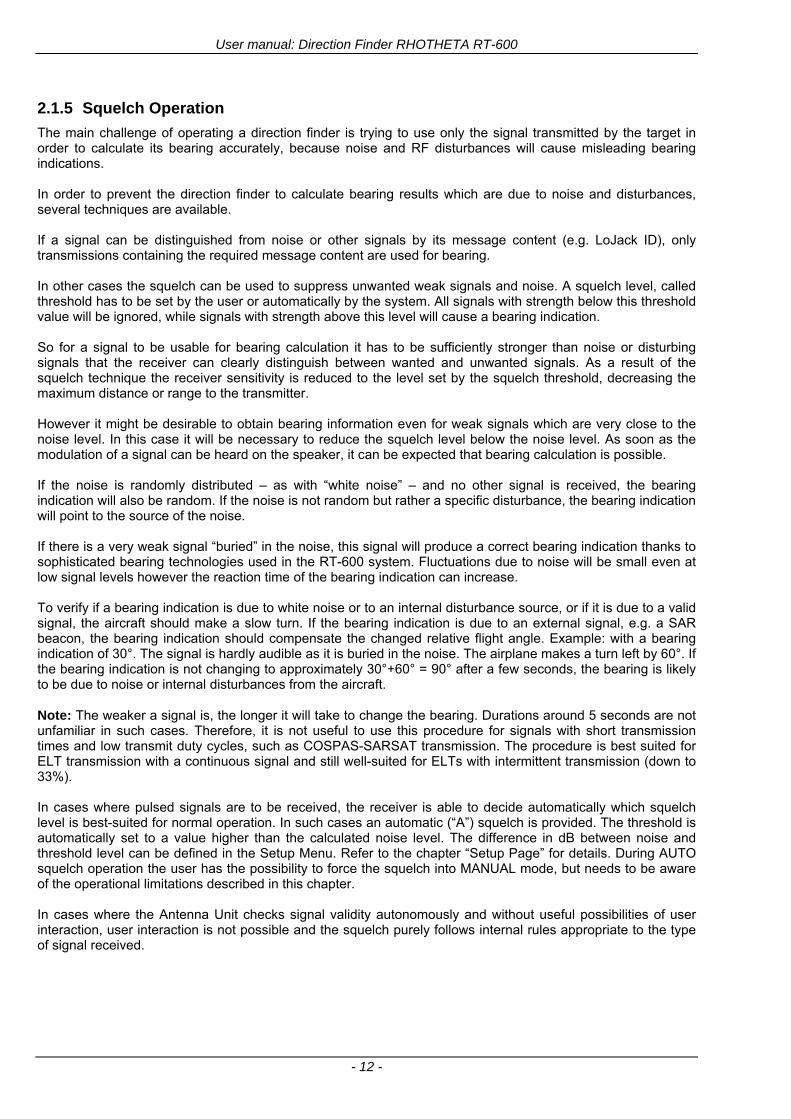
User manual Direction Finder RHOTHETA RT-600
- 12 -
215 Squelch Operation
The main challenge of operating a direction finder is trying to use only the signal transmitted by the target in order to calculate its bearing accurately because noise and RF disturbances will cause misleading bearing indications In order to prevent the direction finder to calculate bearing results which are due to noise and disturbances several techniques are available If a signal can be distinguished from noise or other signals by its message content (eg LoJack ID) only transmissions containing the required message content are used for bearing In other cases the squelch can be used to suppress unwanted weak signals and noise A squelch level called threshold has to be set by the user or automatically by the system All signals with strength below this threshold value will be ignored while signals with strength above this level will cause a bearing indication So for a signal to be usable for bearing calculation it has to be sufficiently stronger than noise or disturbing signals that the receiver can clearly distinguish between wanted and unwanted signals As a result of the squelch technique the receiver sensitivity is reduced to the level set by the squelch threshold decreasing the maximum distance or range to the transmitter However it might be desirable to obtain bearing information even for weak signals which are very close to the noise level In this case it will be necessary to reduce the squelch level below the noise level As soon as the modulation of a signal can be heard on the speaker it can be expected that bearing calculation is possible If the noise is randomly distributed ndash as with ldquowhite noiserdquo ndash and no other signal is received the bearing indication will also be random If the noise is not random but rather a specific disturbance the bearing indication will point to the source of the noise If there is a very weak signal ldquoburiedrdquo in the noise this signal will produce a correct bearing indication thanks to sophisticated bearing technologies used in the RT-600 system Fluctuations due to noise will be small even at low signal levels however the reaction time of the bearing indication can increase To verify if a bearing indication is due to white noise or to an internal disturbance source or if it is due to a valid signal the aircraft should make a slow turn If the bearing indication is due to an external signal eg a SAR beacon the bearing indication should compensate the changed relative flight angle Example with a bearing indication of 30deg The signal is hardly audible as it is buried in the noise The airplane makes a turn left by 60deg If the bearing indication is not changing to approximately 30deg+60deg = 90deg after a few seconds the bearing is likely to be due to noise or internal disturbances from the aircraft Note The weaker a signal is the longer it will take to change the bearing Durations around 5 seconds are not unfamiliar in such cases Therefore it is not useful to use this procedure for signals with short transmission times and low transmit duty cycles such as COSPAS-SARSAT transmission The procedure is best suited for ELT transmission with a continuous signal and still well-suited for ELTs with intermittent transmission (down to 33) In cases where pulsed signals are to be received the receiver is able to decide automatically which squelch level is best-suited for normal operation In such cases an automatic (ldquoArdquo) squelch is provided The threshold is automatically set to a value higher than the calculated noise level The difference in dB between noise and threshold level can be defined in the Setup Menu Refer to the chapter ldquoSetup Pagerdquo for details During AUTO squelch operation the user has the possibility to force the squelch into MANUAL mode but needs to be aware of the operational limitations described in this chapter In cases where the Antenna Unit checks signal validity autonomously and without useful possibilities of user interaction user interaction is not possible and the squelch purely follows internal rules appropriate to the type of signal received
User manual Direction Finder RHOTHETA RT-600
- 13 -
Examples of different squelch settings
Fig 8) Manual squelch mode correct squelch
adjustment
Correct squelch adjustment If the squelch is set to level (b) slightly over the noise level (a) the receiver audio output remains quiet and no wrong noisy bearing is indicated
Fig 9) Manual squelch mode Incorrect squelch
adjustment
Incorrect squelch adjustment If the squelch level is set (b) below the noise level (a) a wrong noisy bearing is indicated
Fig 10) Automatic squelch mode
Automatic squelch mode Automatic squelch mode is indicated by an ldquoArdquo (c) above the squelch level marker Depending on the SN-Ratio setting the squelch level is automatically set slightly higher than the noise level Using the SQL rotary switch (1) the user can change to manual squelch mode Automatic squelch mode can be activated again by setting the squelch level manually to lt 0 or gt 60
Fig 11) Automatic squelch mode with strong signal
Automatic squelch mode with strong signals Strong short receive signals will not modify the squelch level setting
Fig 12) Automatic squelch mode and not adjustable by
the user
Automatic squelch mode level not re-adjustable by user When the squelch is adjusted automatically by the system and the user is not allowed to change it an ldquoXrdquo (c) is displayed above the squelch level marker
User manual Direction Finder RHOTHETA RT-600
- 14 -
22 Frequency (FRQ) Selection Page The Frequency Selection (FRQ Selection) Page allows the user to select a frequency select a band and edit a frequency
Open FRQ Page
From the ldquoDFrdquo standard page activate the Page Rotary Switch in any direction to open the ldquoFRQrdquo Page for Frequency Selection
Fig 13) Open FRQ Page
Fig 14) FRQ ndash Frequency Selection Page
221 Selecting a Frequency
(1) Use the Page knob ldquoFRQrdquo again to select (recall) a frequency from
gtMEMlt four (4) memory channels gtWlt one (1) working (operating) frequency gtFIXlt fixed frequencies gtCPSARlt seven (7) COSPAS-SARSAT channel groups
(2) The actual adjusted frequency
(3) Frequency band-information
Exit Frequency dialogue
(4) Press push-button gtF1lt ldquoEXITrdquo to exit to DF mode (using the actual frequency
222 Recalling and editing frequencies from a memory channel
Recall
(1) With changing the Page rotary knob memory channels 1 4 can be selected The gtmarkerlt symbol indicates the actual memory channel
Edit
(2) MHz plusmn edits the MHz Value of the actual frequency
(3) kHz plusmn edits the kHz Value of the actual frequency
(4) F2 switches to next band
gtMHzlt and gtkHzlt directly changes and overwrites the actual selected memory frequency inside the actual band (see also 224 Editing a Frequency)
Fig 15) Recall frequency of Memory channel 3
User manual Direction Finder RHOTHETA RT-600
- 15 -
223 Recalling frequencies from fixed frequencies or CospasSarsat Channels
Fig 16) FRQ Selection Page with FIX1 selected
(1) ldquoFIXrdquo Selection range for fixed frequencies
for RT-600 Standard version for RT-600 Law Enforcement version
FIX1 ldquoEltPlbrdquo 121500 MHz international VHF air distress emergency frequency
FIX2 ldquoChnl16rdquo 156800 MHz marine VHF emergency radio channel 16
FIX3 ldquoEltMILrdquo 243000 MHz military UHF air distress emergency frequency
FIX1 ldquoEltPlbrdquo 121500 MHz international VHF air distress emergency frequency
FIX2 ldquoChnl16rdquo 156800 MHz marine VHF emergency radio channel 16
FIX3 ldquoLE(USA)rdquo 173xxx MHz LoJack Recovery System
FIX4 ldquoETSSTDrdquo 216487 MHz ETS standard frequency
FIX5 ldquoETSUCVrdquo 216512 MHz ETS ucover frequency
(2) ldquoCPSARrdquo Selection range for Cospas Sarsat channel groups
CPSAR1 ldquo022-028rdquo 406022 hellip 028 MHz Channel A B C
CPSAR2 ldquo031-037rdquo 406031 hellip 037 MHz Channel D E F
CPSAR3 ldquo040-043rdquo 406040 hellip 043 MHz Channel G H
CPSAR4 ldquo046-052rdquo 406046 hellip 052 MHz Channel I J K
CPSAR5 ldquo055-061rdquo 406055 hellip 061 MHz Channel L M N
CPSAR6 ldquo064-070rdquo 406064 hellip 070 MHz Channel O P Q
CPSAR7 ldquo073-076rdquo 406073 hellip 076 MHz Channel R S
User manual Direction Finder RHOTHETA RT-600
- 16 -
224 Editing a Frequency
While on the FRQ SELECTION Page the user can directly edit the frequency displayed
Fig 17) FRQ Selection Page before frequency editing
(1) gtMHzlt Rotary switch for direct adjustment of the displayed MHz range inside the actual band
(1 x step = 1 MHz adjustment)
(2) gtkHzlt Rotary switch for changing the displayed kHz frequency according to the actual band frequency grid (as example 8333 kHz at the VHF airband)
(3) gtF2lt Adjustment of the next available band (see next page gtgt Selecting a Frequency Band)
Fig 18) FRQ Selection Page after frequency editing
If the selected and marked frequency is not one of the MEM [14] channels then the changed frequency is automatically stored in the work frequency WorkFRQ channel
User manual Direction Finder RHOTHETA RT-600
- 17 -
225 Selecting a Frequency Band
While on the FRQ Selection Page each available band can be selected by pressing F2 BAND
(1) Press push button F2 BAND for
switch over to the next band
(2) Designation of actual selected band
(3) Max frequency limits of the actual selected band (depends on wide band options)
Fig 19) FRQ Selection Page (bands)
Frequency bands availability depends on the system version (A LE) and its wide band options (F1 to F4) These optional wide bands are available if ordered in addition to the default bands Here is a listing of DEFAULT and OPTIONAL bands available with each version of the system RT-600 (STANDARD) Listing of bands
Default bands available OPTIONAL extended bands available
Band designation Frequency limits Option Designation Frequency limits
VHF Emergency Band 118000 hellip 124000 MHz gt F1 VHF Air Band 118000 hellip 136992 MHz
VHF Marine Band 154000 hellip 163000 MHz gt F2 Extended VHF Marine 137000 hellip 224995 MHz
UHF Emergency Band 240000 hellip 246000 MHz gt F3 UHF Air Band 225000 hellip 399975 MHz
COSPAS SARSAT 400000 hellip 406092 MHz
UHF FM Band 406100 hellip 410000 MHz gt F4 Additional UHF FM 406100 hellip 470000 MHz
RT-600 (Law Enforcement) Listing of bands
Default bands available OPTIONAL extended bands available
Band designation Frequency limits Option Designation Frequency limits
VHF Emergency Band 118000 hellip 124000 MHz gt F1 VHF Air Band 118000 hellip 136992 MHz
VHF Marine Band 154000 hellip 163000 MHz gt F2 Extended VHF Marine 137000 hellip 163000 MHz
LoJack 164000 hellip 174000 MHz
ETS 216000 hellip 220000 MHz
COSPAS SARSAT 400000 hellip 406092 MHz
User manual Direction Finder RHOTHETA RT-600
- 18 -
23 Direction Finder (DF) Mode Direction Finder (DF) mode is generally used to display all valid information processed by the DF from the signal received from a target transmitter The amount and kind of information displayed by the DCU depends on the type and content of the signal received and processed by the DF Simple signals such as the analog sweep-tone modulation received from a SAR beacon (ELT PLB EPIRB PDD) on 121500 MHz allow displaying only basic bearing information while digital signals such as COSPAS-SARSAT and LOJACK allow displaying more information for ex beacon IDs GPS coordinates codes VLUs etc
231 Operating Elements in DF Mode
Fig 20) Operational Elements in DF Mode
This picture shows the DCU operating in DF Mode on the international emergency frequency 121500 MHz
with an active signal being received (1) gtFREQUENCYlt Rotary switch activates the ldquoFRQrdquo frequency page for changing and selecting the
active frequency The last selected frequency remains stored after switching offon the device The selected frequency is shown on the graphic display bottom right Above additional information for the selected frequency is displayed The use of the rotary switch activates a sub-page Please refer to the Frequency Selection section for details
(2) gtVOLUMElt Rotary switch to adjust the audio output level The volume of a linked external speaker or amplifier can be adjusted in a range from 0 (off) to 99 (maximum loudness) The selected volume is shown in the bottom left corner of the graphic display The volume remains stored after switching offon the device
(3) gtSquelch Levellt adjusts the squelch level The squelch level has to be above the receiving level without signal (noise) Only signals above the squelch level are audible in the loudspeaker and used by the direction finder for bearing indication The gtSQLlt rotary switch allows to select the squelch threshold ie a minimum signal strength of an incoming signal to be processed The current settings on a signal level scale from 0 to 60 is shown in bright letters on dark background below the SQL rotary switch and as an arrow beside the signal Strength Bar-Graph
(4) The gtCLRlt Push-button is used for erasing the internal bearing value averaging store and the Last Signal Timer To activate this function the push-button has to be hold down for a minimum of circa two seconds The sophisticated averaging store increases bearing precision and enables at all an usable
User manual Direction Finder RHOTHETA RT-600
- 19 -
bearing display in case of bad receiving signals (if there is a far away transmitter andor temporary complete loss of a receiving signal) Caused by the averaging procedure a drag error may occur which might be disturbing the bearing indication after a quick change of course of the aircraft or vehicle In this case the indicated bearing value lags by the real bearing value for about two seconds (for very weak signals even longer) By pressing this push-button after a quick change of course the display will show the new bearing value without drag error Additionally the F1CLR Push-Button is used to activate specific functions high-lighted in the menu below the button by pushing it for a short time (here as example ldquoSCANrdquo starts scanning the actual air band)
(5) gtSTORElt push-button Without function except if a special function is high-lighted in the menu line of the display
(6) gtREPEATlt Push-button when pressed and hold for min 3 sec the last valid bearing value with corresponding receiving level is displayed
232 Standard Display in DF Mode
Fig 21) DF Mode
(1) gtRelative Bearing valuelt by means of a sophisticated averaging procedure a steady display is
accomplished as graphic display and as text in the range of 0deghellip 359deg (0deg corresponds to bearing direct ahead)
(2) gtSpreadlt maximum deviation of un-averaged bearing values This is an indicator of bearing quality The wider the range between the directions of maximum deviation the worse the received signal is As a result of the excellent averaging procedure even with a spread of 45deg good bearing results are achieved
(3) gtReceiving levellt (field strength) of the signal as a relative percentage value visualized as bar-graph indication and as decimal value Even without a received signal a certain noise level may be displayed
(4) gtSquelch levellt (independently adjustable and stored for each frequency band) Squelch level is indicated as marker at the Signal Strength Bar-Graph or as direct relative level value A usable bearing analysis can only be achieved if the squelch level is above the noise level (without received signal) If the antenna unit is placed close a heavily disturbing electronic devices the squelch level has to be raised thus making the direction finder being less sensitive In receive modes where the squelch level is set automatically an ldquoArdquo above the marker indicates the ldquoAutosquelchrdquo functionality
(5) gtLast Signallt timer showing the time since a signal has been received for the last time (ie since a signal has been stronger than the squelch level) Values are ldquominutes secondsrdquo
User manual Direction Finder RHOTHETA RT-600
- 20 -
233 Special Options in COSPAS-SARSAT DF Mode
Especially for the use together with beacons transmitting a data signal according to COSPAS-SARSAT specifications in the 406-MHz-Band special functionalities and pages are being provided After selection of a COSPASSARSAT Frequency (Refer to the chapter ldquoFrequency selection Pagerdquo) the bearing page provides additional information and operating options
Fig 22) Operational Elements and Display in COSPAS-SARSAT DF Mode
(1) gtAuto Squelchlt indication indicating that the squelch level is set automatically to be close to the noise
floor It is recommended to always use the Auto Squelch during COSPAS-SARSAT operation This can be achieved by manually selecting 0 (lowest possible value) or 60 (highest possible value) as squelch level During COSPAS-SARSAT-Operation this will force the automatic setting of the level
(2) gt121500lt menu option The COSPAS-SARSAT signal in the 406 MHz band is transmitted only every 50 seconds in form of a short data burst of 440 or 520 ms approaching the transmitter it will be received earlier than the 121500 MHz continuous signal due to its high transmitter power However in a lower distance to a transmitter bearing on 121500 MHz is faster thanks to the continuous or rapidly intermittent signal The 121500 MHz menu option allows a direct switch-over to 121500 MHz Direct return back from 121500 to the COSPAS-SARSAT band is possible from the 121500 MHz bearing Window in COSPAS-SARSAT mode Please refer to the chapter ldquo121500 MHz bearing Window in COSPAS-SARSAT moderdquo for details
(3) gtDecodelt menu option allows to open the COSPASSARSAT Decode sub-page by shortly pushing the F2 push-button above the menu option
(4) gtFrequency rangelt indication COSPAS-SARSAT is using a channel spacing of 3 kHz for its beacons Due to the internal architecture of the direction finder it is possible to receive more than one channel in the same time Thus frequency steps of the direction finder are 833 kHz instead of 3 kHz The receive frequency covered by the current receive frequency setting is shown in the display line above the receive frequency indication
Important If the exact frequency of the COSPAS-SARSAT beacon is unknown it is strongly recommended to use the COSPAS-SARSAT scanning functionality in order to detect the correct frequency (Refer to the chapter ldquoFrequency selection Pagerdquo amp ldquoCOSPAS-SARSAT Scan Moderdquo)
User manual Direction Finder RHOTHETA RT-600
- 21 -
234 COSPAS-SARSAT Decode Window
The COSPAS-SARSAT Decode Window allows decoding incoming COSPAS-SARSAT data messages Only while this decode window is activated the decoding is possible An already received COSPAS-SARSAT puls while DF bearing mode was activated can not be used for decoding afterwards In this case the user has to wait while this decode window is active for the next transmitted puls approx 50 sec later
Fig 23) COSPAS-SARSAT Beacon Information Page
(1) gtExitlt push button (F1 button) allows to exit the decode window and switch back to the COSPAS-
SARSAT DF Mode page
(2) gtSARSATlt in the upper right corner of the display indicates that the COSPAS-SARSAT decode function is activated
(3) gtCountrylt displays the COSPAS-SARSAT Country Code coded into the received data message
(4) gtLast Signallt time since the last COSPAS-SARSAT message has been received in minutes secondsrsquo format
(5) gtPositionlt field showing in case of location protocols being used by the beacon the encoded GNSS position data (latitude longitude) transmitted by the beacon
(6) gt15-HEX-IDlt 15-HEX-ID of the beacon in hexadecimal format
(7) gtData stringlt of the bits 25 to 112 of the COSPAS-SARSAT data burst in case of short messages and bits 25 to 144 in case of a long message format The last 8 Hex Values are separated by a blank Bit- and Frame-synchronization hex values (Bits 1 to 24) are suppressed to increase the readability of the data message
(8) gtXlt sign to indicate that the Squelch is controlled by the antenna unit for optimum sensitivity The user has no access to the Squelch setting
User manual Direction Finder RHOTHETA RT-600
- 22 -
235 Tracking 121500 MHz while in COSPAS-SARSAT Mode
While in COSPAS-SARSAT DF Mode the user can switch to 121500 MHz in order to track the beacon in VHF If a valid signal is not received in 121500 MHz the user can switch back to the last active COSPAS-SARSAT channel (406 MHz frequency) being tracking previously
Fig 24) Tracking 121500 MHz while in COSPAS-SARSAT Mode
Differences are (1) gt406xlt press F1 to switch back to the last
COSPAS-SARSAT channel (406 MHz frequency) being tracking previously
(2) gt121500 MHzlt Actual frequency being tracked
User manual Direction Finder RHOTHETA RT-600
- 23 -
236 COSPAS-SARSAT Scan Mode
If the COSPAS-SARSAT Scan Mode has been selected at the frequency selection page ldquoFRQrdquo the COSPAS-SARSAT channels as selectable manually from the Frequency Selection Page are scanned After reception of a COSPAS-SARSAT Signal the scanning is stopped at the received frequency Due to the fast scanning ndash the complete COSPAS-SARSAT sub-band is scanned within less than 400 ms ndash detection of a receivable COSPAS-SARSAT signal is possible within one COSPAS-SARSAT repetition cycle
Fig 25) FRQ Selection Page with SCN COSPAS-SARSAT Scan Page selected
At the frequency selection page an active COSPAS SARSAT scanning can be stopped by de-activating it with the rotary button (1) While the scanning is active it is also possible by pressing gtF1lt ldquoEXITrdquo to switch back to the DF pagehellip
Fig 26) DF page with active COSPAS-SARSAT Scan Mode at the DF page
(1) gtSCANlt flashing indication notifying the user that the equipment is operating in scan mode
(2) Frequency display indicating the COSPAS-SARSAT scanning frequency range
(3) gtXlt sign showing that squelch settings are controlled autonomously by the receiver
Scan mode can be left by pressing gtF1lt ldquoSTOPrdquo
User manual Direction Finder RHOTHETA RT-600
- 24 -
237 Marine Ship Scan Mode
Fig 27) DF Mode FRQ = 156800 MHz F1 for scan function
If the active frequency (2) is within the VHF Marine Band a fast scan of all ship channels is possible by pushing gtF1lt ldquoSCAN (1) In this scanning mode all marine channels 1 to 88 (156025 to 157450 MHz) are scanned continuously until a signal is received To offer the best monitoring functionality for the user also signals between to channels (4) are detected (scanning without gap) In order to prevent the scan to stop on noisy frequencies it is recommended to start scanning with high squelch settings You can reduce the squelch level in steps until the scan stops on a noisy frequency for the first time Then increase the squelch level slightly This will result in the highest possible scan sensitivity and avoiding noisy channels due to RF disturbances sometimes generated by other equipment in own aircraft
Fig 28) DF Mode active scanning in process
The scanning is stopped by pressing gtF1lt ldquoSTOPrdquo (3)
User manual Direction Finder RHOTHETA RT-600
- 25 -
24 Law Enforcement Operation Law enforcement special ops and other organizations use the RT-600 LE (LAW ENFORCEMENT) version instead of the RT-600 A (STANDARD) version One of the reasons is that the LE version features scanning and tracking of signals like LoJack and ETS as well as signals in the 216000 MHz ndash 220000 MHz band such as medical beacons wristankle transmitters cashasset recovery ldquotagsrdquo etc However the LE version shares many functions in common with the A version such as scanning and tracking in the AIR band COSPAS-SARSAT band etc
241 Power-On procedure
The power-on procedure is the same as described in 211
(1) System Version ldquo(L)rdquo for LAW ENFORCEMENT version
Fig 29) STARTUP Screen (see 211 for details)
242 LoJack Scan Mode Start scanning for a VLU Code
For the convenience of Law Enforcement and other special ops users who frequently engage in tracking SVRS (Stolen Vehicle Recovery System) signals such as LoJack (LoJack Corp FCC 9020 Part 2 SVRS) RHOTHETA has optimized the power-on procedure of the RT-600 LE version so that right after the STARTUP screen the unit displays automatically the LoJack Scan Mode page to start immediately scanning for a valid VLU (Vehicle Location Unit) code without pressing any key
Fig 30) LoJack Scan Mode unit is scanning for a LoJack VLU Code
(1) gtscan LoJacklt DF is scanning for any new LoJack VLU Code
(2) gtEXITlt press F1 to exit and switch directly to DF Mode
User manual Direction Finder RHOTHETA RT-600
- 26 -
243 LoJack Scan Mode from any other page
While operating on any page other than the LoJack Scan page the user can switch directly to LoJack Scan Mode by pressing Hotkey F2 for 2 secs
(1) press Hotkey F2 for 2 secs to switch to the LoJack Scan page
Fig 31) Hotkey F2
User manual Direction Finder RHOTHETA RT-600
- 27 -
244 Manual activation of LoJack Scan Mode
(1) select the LoJack frequency (see also Frequency Selection Page)
(2) press F1 to switch back to the DF MODE
Fig 32) FRQ Selection Page FRQ = LoJack BAND = LoJack (164-174 MHz)
While in DF MODE with adjusted LoJack frequency the user can switch directly to the LoJack Scan by pressing gtF1lt ldquoSCANrdquo
(1) press F1 SCAN to switch to the LoJack Scan page
(2) still no LoJack ID filter used (ID=off) all transmissions are received on the active frequency as example also unwanted tower pulses
Fig 33) DF Mode with LoJack filter OFF
User manual Direction Finder RHOTHETA RT-600
- 28 -
245 Receiving and accepting a new VLU Code
While in LoJack Scan Mode waiting for a VLU Code if a new VLU Code is displayed the user can accept it and switch directly to DF Mode by pressing F2
(1) a new LoJack VLU Code (0001A) has been received
(2) press F2 to accept the new VLU Code (0001A) and switch to DF MODE page with the LoJack filter activated to track only 0001A
Fig 34) LoJack Scan Mode with new VLU Code received
246 Entering a new VLU Code manually
While in LoJack Scan Mode the user can enter a LoJack VLU code also manually
(1 2 3) use the SELECTplusmn and plusmnVALUE knobs to enter a new LoJack VLU Code active ID (0001A)
(4) Press F1 to accept the new VLU Code and switch to DF Mode with the LoJack filter ON to track only 0001A
Fig 35) LoJack Scan Mode with new VLU Code entered manually
User manual Direction Finder RHOTHETA RT-600
- 29 -
247 Tracking one VLU Code while monitoring new VLU Codes
While on DF Mode and tracking a VLU Code (0001A) the user can turn the LoJack switch OFF with F2 also the user can start scanning all VLUs again with F1
0001A is displayed as the active VLU Code filter function is ON only 0001A is tracked
Monitoring of other VLU Codes is active in the background
(1) Press F1 to switch to the LoJack Scan Mode to scan for new VLU Codes
(2) Press F2 to switch LoJack filter OFF
Fig 36) DF Mode with active VLU Code and LoJack filter ON
248 Tracking one VLU Code and receiving a new VLU Code
While on DF MODE page and tracking VLU Code (0001A) in the background a new VLU Code is received and decoded (G2HC7)
(1) The new VLU Code is announced (NEW G2HC7)
(2) Press F1 to switch to LoJack Scan Mode to see the arrival time of G2HC7 and the possibility to change bearing to this new G2HC7
Fig 37) DF Mode with active VLU Code and announcement of new VLU Code
User manual Direction Finder RHOTHETA RT-600
- 30 -
249 Switching to a new VLU Code
While on the LoJack Scan Page tracking one VLU Code (0001A) and notified of a new VLU Code (G2HC7)
(1) press F1 to continue tracking 0001A
(2) press F2 to start tracking G2HC7
(3) Time elapsed since G2HC7 was last received
(4) Time elapsed since 0001A was last received
If F1 is pressed for 2 sec the indicated VLU Code (G2HC7) and ID (0001A) are deleted
Fig 38) LoJack Scan Page with one active VLU Code and one new VLU Code
2410 ldquoBlockingrdquo function of one LoJack VLU Code
The LoJack scan page can also be used to ldquoblockrdquo one unwanted LoJack VLU ID signal by separating the adjusted active ID from any other received LoJack VLU signal This is done by muting the audio (see example below) when a LoJack signal with VLU code ldquo0001Ardquo is received gtgt Any new VLU Code (active LoJack signal) - except for 0001A ndash will be displayed on the top row and generate the audible beep tone
Fig 39) LoJack Scan Page with one active VLU Code and audio OFF
Tip ldquoBlockingrdquo is an important tool for practical missions As example a stolen vehicle with VLU ID ldquo0001Ardquo was tracked in the DF bearing mode The mission
is completed but the VLU is normally still transmitting With the settings above only new VLU signals except the now unwanted ldquo0001Ardquo are audible and displayed in the upper (scan LoJack hellip for new VLU) box
User manual Direction Finder RHOTHETA RT-600
- 31 -
2411 Tracking in the 216 to 220 MHz band
The RT-600 features scanning and bearing functionality in the 216000 MHz to 220000 MHz band The 216000 MHz ndash 220000 MHz band contains frequencies and signals used by special services and tracked by law enforcement special ops and similar organizations These are some of the frequencies and services in this band
CFR 90259 tx 216000 MHz to 220000 MHz
Low Power Radio Service (LPRS) tx 216000 MHz to 217000 MHz
Medical beacons Project Lifesaver tx wristankle tx 213000 MHz to 216000 MHz
ETS tx stolen cashasset recovery tx ldquobaitrdquordquotagrdquo tx 216000 MHz to 220000 MHz tx = transmitter(s) However any future or current user of the Rhotheta RT-600 must be aware that tracking signals on the frequencies listed above may be challenging and even frustrating due mostly to negative factors in some of the transmitters
bull Very low RF power output
bull Inefficient antennas
bull Battery-powered devices with a ldquolow batteryrdquo condition
bull Devices worn or located in conditions of poor RF propagation
bull Devices with channel spacing different than the one specified for the RT-600
These factors can make it very difficult for the DF to receive the signal andor display an accurate bearing Disclaimer For the reasons explained above and even though the RT-600 features top performance in its class RHOTHETA does not offer - and is not to be held responsible for - any guaranteed minimum range or distance to a transmitter in this band
25 Setup Edit Page System settings are displayed in the setup page The functions described in this section should be used by trained personal only
Fig 40) Accessing the Setup Page
The setup page can be accessed by holding down the gtCLRlt (1) and gtREPlt (2) buttons simultaneously and in the same time performing a left-hand turn on the gtPagelt rotary switch (3)
User manual Direction Finder RHOTHETA RT-600
- 32 -
Fig 41) Setup Page
(1) gtStorelt push-button must be pressed in parallel if a value of a setting shall be modified If a value can
be modified the background stops to blink
(2) gtSelectlt rotary switch used to scroll through the menu options The value of the actually activated menu option is high-lighted with dark background and blinking
(3) gtValuelt rotary switch used to change values in menu options (gtStorelt (1) has to be pressed in parallel if a value shall be modified)
(4) gtSN-Ratiolt menu option representing the necessary Signal-To-Noise-Ratio (Difference between signal and noise level) used as criterion for the automatic squelch function Please refer to the chapter ldquoSquelch Operationrdquo for details Default value is 60 dB
(5) gtMounting Positionlt menu option to select Top- or Bottom-Mounting of the DF antenna In case of rooftop installation (eg on land vehicles) ldquoToprdquo shall be selected In case of bottom-down (upside-down) installation (eg on a helicopter) ldquoBotrdquo shall be selected If this option is not selected correctly all bearing values will be mirror-inverted
(6) gtBearing Offsetlt menu option to include a constant offset correction to the bearing indication Bearing values in degrees will be changed according to the offset value
(7) gtMaximum External Dimming Voltage for Legendslt menu option which sets the upper limit of the dimming input voltage for the legends-panel Range=[15 hellip 28]V
(8) gtMinimum External Dimming Voltage for Legendslt menu option which sets the lower limit of the dimming input voltage for the legends-panel Range=[15 hellip 28]V
(9) gtPagelt rotary switch to be turned right-hand to go back to the Direction Finder page A left-hand turn on this rotary switch will show up an additional service page with debug information used for system checks
(10) gtExtended Seriallt It is possible to enable or disable the extended serial data protocol Only of interest if serial data is used by any connected control units like moving maps or computers For detailed information see (Serial interface data protocol (short description)gt at page 46) If there are compatibility problems with already existing older remote control software it is recommended to switch OFF the extended serial data protocol
User manual Direction Finder RHOTHETA RT-600
- 33 -
3 Error messages If an internal error of the device is recognized a corresponding flashing error message will be shown in the DF pages
Fig 42) Error Messages
(1) Error message including error code (in brackets)
(2) Short description of the indicated error
In case of coincidence of various errors the error with the highest priority will be displayed
Error message Error location Reason
Error (12) VOLTDU
Main voltage supply Main Voltage input too low ( 100 V)
Error (11) NO AU
Connection antenna display or Antenna Unit
No serial data (RS485) from Antenna Unit No or damaged connection between antenna and display or damaged antenna unit
Error (10) BAD AU
Connection antenna display
Incompatibility or bad data connection between display and antenna
Error (9) BAD RU
Remote Unit Incompatibility or bad data connection between display and external serial Remote Unit or PC
Error (8) VOLTAU
Antenna Unit Voltage supply at Antenna Unit too low ( 90 V) Main voltage supply too low or considerable drop of voltage between display and antenna
Error (7) BAD DCU
Connection Display Antenna
Incompatibility or bad data connection between antenna and display
Error (6) NO DCU
Connection Display Antenna
No serial data from Display Control Unit to Antenna Unit
Error (5) PLL ERR
antenna Error in synthesizer-oscillator of receiver in Antenna Unit
Error (4) FRQ+OFS
received transmitter Received frequency too high (more than 6 KHz error of transmitter)
Error (3) FRQ-OFS
received transmitter received frequency too low (more than 6 KHZ error of transmitter)
Error (2) DECODE
radio distance transmitter DF
Data Bits of decoded signal (COSPAS-SARSAT or LoJack) defective
Error (1) DATARNG
Incompatibility of data DCU AU
Protocol data bytes out of valid range
Error (0) NO REC
Antenna Unit receiver
Receiver board defective
User manual Direction Finder RHOTHETA RT-600
- 34 -
4 Installation
41 Antenna unit A convenient position of the monopole bearing antenna is crucial for good bearing results The antenna needs an effective ground connection to the body of the aircraft or to the roof of the vehicle If there is no metallic mounting surface available a metallic sheet or similar (net) with connection to ground has to be applied first between vehicle-body and antenna In this hatched area the antenna touches the body ofthe vehicleaircraft In order to obtain a good groundconnection the surface of the body should be bared(Measuring unit [mm])
8 x holes for mounting the antenna unit to the
vehicle aircraft
Fig 43) Antenna Mounting Drawing
User manual Direction Finder RHOTHETA RT-600
- 35 -
411 Influence of antenna location and environment on the bearing accuracy
Recommendations concerning the practical antenna unit location on helicopters and airplanes
The bearing accuracy of the direction finder antenna unit is severely influenced (comparable to an airspeed sensor) by the environment For comparison a perfect high quality speed sensor will not indicate the true airspeed if this sensor is interfered by strong turbulences The direction finder antenna unit acts as a sensor for electromagnetic waves In the near field of this antenna unit any conductive (eg metallic) obstacle will influence the incoming wave field and create reflections which decrease the bearing accuracy These are general physical limitations concerning all types of direction finder systems To achieve the best bearing results it should be considered that the antenna unit is installed as far away as possible from any other vertically polarized conductive structure If possible there should be no reflectors within an area of 2-3 feet around the antenna unit In this worst case example the direction finder will not work properly
Fig 44) Antenna Installed in a Bad Location
In this example the antenna unit is located too close to the cable cutter of the helicopter This cutter will produce strong reflections especially as the length is equal to Lambda4 within the VHF airband
User manual Direction Finder RHOTHETA RT-600
- 36 -
Examples of properly installed direction finder antenna units
Fig 45) Antenna Installed in Good Locations
User manual Direction Finder RHOTHETA RT-600
- 37 -
42 Display and Control Unit
The display control unit may be mounted into a front panel by the means of this mounting drawing
Fig 46) DCU Mounting Drawing
(all dimensions in [mm]) To install or uninstall the display control unit perform the following steps (1) Remove the cover caps of the four rotary switches
(2) Loose the screws visible below the position of the cover caps
(3) Remove the plastic button from the axis of the four rotary switches
(4) Mount dismount the display control unit
(5) Re-install the plastic buttons on the axis of the four rotary switches
(6) Fix the screws so that the plastic buttons are fixed on the axis
(7) Re-install the cover caps on the four rotary switches
User manual Direction Finder RHOTHETA RT-600
- 38 -
43 System Interconnect Wiring Diagram (Also refer to chapter ldquoTechnical Datardquo for details)
Fig 47) System Interconnect Wiring Diagram
6-pol Amphenol plug femalePTG06SE10-6S(SQ)
max length of cable 20 m 9-pol Sub-D plug (femalemale)
User manual Direction Finder RHOTHETA RT-600
- 39 -
5 Technical Data
51 Electric features
Method of bearing Doppler-principle (3 kHz rotational frequency right left rotation)
Bearing accuracy1 plusmn 5deg RMS
Internal resolution 1deg
Bearing Sensitivity VHF AirEmergency le 25 μVm (typical)
VHF Marine le 25 μVm (typical)
UHF Emergency and ETS le 4 μVm (typical)
COSPAS-SARSAT le 4 μVm (typical)
LoJack Decoding (50 Message Error Rate) and bearing le 5 μVm (typical)
Frequency stability plusmn 20 ppm (Δff = plusmn210-6)
Reception frequencies
SAR version (Standard)
Frequency Options
VHF Emergency Band 118000 to 124000 MHz (833 kHz steps AM)
VHF Marine Band 154000 to 163000 MHz ( 500 kHz steps FM) (channel 16 selectable via channel no)
UHF Emergency Band 240000 to 246000 MHz (2500 kHz steps AM)
UHF FM Band 406100 to 410000 MHz ( 500 kHz steps FM)
COSPAS-SARSAT 400000 to 406092 MHz Including 406022 to 406076 MHz (Channel A S)
F1 VHF Air Band 118000 to 136992 MHz
F2 extended VHF Marine Band 137000 to 224995 MHz
F3 extended UHF Air Band 225000 to 399975 MHz
F4 additional UHF FM Band 406100 to 470000 MHz
Reception frequencies
LAW Enforcement version
Frequency Options
VHF Emergency Band 118000 to 124000 MHz (833 kHz steps AM)
VHF Marine Band 154000 to 163000 MHz (500 kHz steps FM) (channel 16 selectable via channel no)
LoJack 164000 to 174000 MHz (125 kHz steps FM)
ETS 216000 to 220000 MHz (10125 kHz AM)
COSPAS-SARSAT 400000 to 406092 MHz Including 406022 to 406076 MHz (Channel A S)
F1VHF Air Band 118000 to 136992 MHz
F2 extended VHF Marine Band 137000 to 163000 MHz
COSPAS-SARSAT fast scan mode
Full automatic detection of any active COSPAS-SARSAT channel A to S within 400 ms
COSPAS-SARSAT decoding
Reception and decoding of COSPAS-SARSAT data signal (112 or 144 bit) specified according to COSPAS-SARSAT
LoJack decoding Selectable LoJack ID display and selective active filtering
Special scanning modes
complete maritime ship band scanning within 3 s (channel 01 hellip 88 also frequencies between 2 channels are included)
1With undisturbed wave field and sufficient field strength Measuring by changing the angle of incidence with the antenna rotating on a revolving table in order to eliminate environmental influences on the results No modulation
User manual Direction Finder RHOTHETA RT-600
- 40 -
Bearable modulation A3E F3E A3X (ELT-modulation) F1D G2D COSPAS-SARSAT Bearing largely independent of modulation
Polarization Vertical
Polarization error 5deg at 60deg field vector rotation
Garbling cone Ca 30deg to the vertical
Time of response2 50 ms (with sufficient reception field strength)
LC-graphic display 128 x 64 pixels supertwist transflective extended range of temperature dark-blue display on yellow-green background background light Freely adjustable (exponential) dimming of brightness
NVG cockpit design Fully compatible NVIS Green B display Control Unit optional
Operating voltage 275 V nominal 12 V to 35 V DC
Current consumption LCD-background light Off max 500 mA (12 V DC) max 250 mA (24 V DC)
LCD-background light 100 max 750 mA (12 V DC) max 350 mA (24 V DC)
LCD-background light 100 max 900 mA (12 V DC) with NVG Option max 400 mA (24 V DC)
Audio out For external speaker approx 2 W (4 Ω)
Serial data interface Serial interface RS-232 (9600 baud 8 data bits 1 stop bit no parity)
2Very weak signals can considerably increase the time of response
User manual Direction Finder RHOTHETA RT-600
- 41 -
52 Interface External connections (optional at Sub-D 9-pol Male connector)
Dimming
Pin 8
external voltage input for variable dimming of legends
(optional)
Analog input signal for variable control of the legends illumination Input voltage range is freely adjustable in the range of 15 hellip 28 V in the setup menu Refer to chapter ldquoSetup Pagerdquo Default setting 8 hellip28 V (8 V = Off 28 V = max dimming for legends)
Input Impedance gt 50 k
Pin 6 night status line for LCD
dimming (optional)
Low-active (as example switch to ground) At input voltage lt 25 VDC the LCD dimming operates in nightNVG mode Maximum brightness ca 4 of daydefault mode brightness
Input Impedance gt 50 k
Pin 4 NVG status line for LCD
dimming (optional)
Low-active (as example switch to ground) At input voltage lt 25 VDC the LCD dimming operates in nightNVG mode Maximum brightness ca 4 of daydefault mode brightness
Input Impedance gt 50 k
AudioLF
Pin 7 Audio output signal
AC coupled voltage source with very low inner resistance Maximum output voltage ca 8 VPP = 283V RMS at maximum Volume Maximum output power ca 2 W with 4 speaker
If a headphone is connected ([32hellip600] 100mW) we recommend using a resistor (18 025 W) between audio output and headphone to prevent damage of the headphone
Serial interface RS232 (9600 baud 8 data bits 1 stop bit no parity)
Pin 3 TXD Serial output (ca plusmn10 V)
Pin 2 RXD Serial input (ca plusmn10 V)
User manual Direction Finder RHOTHETA RT-600
- 42 -
53 Mechanical features
Temperature range
Display Control Unit permissible operating temperature3 -20 degC +60 degC permissible storage temperature -30 degC +80 degC
Antenna Unit permissible operating temperature3 -40 degC +60 degC permissible storage temperature -55 degC +80 degC
Protective system Antenna Unit IP 67
Weights Display Control Unit 250 g Antenna Unit 2000 g
Dimensions Display Control Unit 82 mm x 82 mm x 43 mm (width x height x depth) Antenna Unit 270 mm x 185 mm
Fig 48) DCU Mechanical Drawing (all dimensions in [mm])
3 For temperatures lower than ndash10deg C a warm-up period of 15 min should be allowed
User manual Direction Finder RHOTHETA RT-600
- 43 -
Fig 49) AU Mechanical Drawing (all dimensions in [mm])
User manual Direction Finder RHOTHETA RT-600
- 44 -
6 Appendix
61 Frequency Ranges
User manual Direction Finder RHOTHETA RT-600
- 45 -
62 Frequencies of channels on maritime band (only for standard [A] version) Frequency-range of the RT-600 in the maritime band 156000 MHz 162025 MHz
Channel No frequency (ship - station) Frequency (coast - station)
1 156050 MHz 160650 MHz 2 156100 MHz 160700 MHz 3 156150 MHz 160750 MHz 4 156200 MHz 160800 MHz 5 156250 MHz 160850 MHz 6 156300 MHz 160900 MHz 7 156350 MHz 160950 MHz 8 156400 MHz 9 156450 MHz
10 156500 MHz 11 156550 MHz 12 156600 MHz 13 156650 MHz 14 156700 MHz 15 156750 MHz 16 156800 MHz 17 156850 MHz 18 156900 MHz 161500 MHz 19 156950 MHz 161550 MHz 20 157000 MHz 161600 MHz 21 157050 MHz 161650 MHz 22 157100 MHz 161700 MHz 23 157150 MHz 161750 MHz 24 157200 MHz 161800 MHz 25 157250 MHz 161850 MHz 26 157300 MHz 161900 MHz 27 157350 MHz 161950 MHz 28 157400 MHz 162000 MHz 60 156025 MHz 160625 MHz 61 156075 MHz 160675 MHz 62 156125 MHz 160725 MHz 63 156175 MHz 160775 MHz 64 156225 MHz 160825 MHz 65 156275 MHz 160875 MHz 66 156325 MHz 160925 MHz 67 156375 MHz 68 156425 MHz 69 156475 MHz 70 156525 MHz 71 156575 MHz 72 156625 MHz 73 156675 MHz 74 156725 MHz 75 156775 MHz 76 156825 MHz 77 156875 MHz 78 156925 MHz 161525 MHz 79 156975 MHz 161575 MHz 80 157025 MHz 161625 MHz 81 157075 MHz 161675 MHz 82 157125 MHz 161725 MHz 83 157175 MHz 161775 MHz 84 157225 MHz 161825 MHz 85 157275 MHz 161875 MHz 86 157325 MHz 161925 MHz 87 157375 MHz 161975 MHz 88 157425 MHz 162025 MHz
User manual Direction Finder RHOTHETA RT-600
- 46 -
63 Serial interface data protocol (short description)
631 General
Interface parameters RS232 9600 Baud 8 databits 1 stopbit no parity LSB sent first Timing of serial data For accurate use of the serial data (even for the optional serial input commands) the correct timing is mandatory The DCU (Display Control Unit) sends out via the RS-232 Pins (see 43 System Interconnect Wiring Diagram page 38) cyclic and autonomous every approx 250300 ms a binary data stream which contains all relevant DF-bearing information The output data contains one or two blocks of binary data (see next picture with accordingly description) The optional serial input is only used if changes (as example frequency change) are done by additional remote control units
Fig 50) Timing of serial data
Serial standard output
This output data is always available and contains all relevant DF-bearing data For detailed content see page 47
Optional extended serial output
This data contains some additional information like as example CospasSarsat or LoJack decoding and ID data For detailed content see page 50 The data is only available with DCU Software [Rev ge 320] and if this optional data block is configured as ON = enabled (see Setup Edit Page point (10) )
Even to avoid compatibility problems with already existing older remote control software it is possible to disable switch off this additional data block (see Setup Edit Page point (10) )
Optional serial input
Only used for optional commands to control DCU parameters If as example the direction finder frequency is changed remotely there is send to the DCU one time this data block with the new frequency For detailed content see page 52
User manual Direction Finder RHOTHETA RT-600
- 47 -
632 Serial standard output (protocol description)
Specification serial standard output
The binary data stream with a length of 39 bytes starts with a header byte (value = hex 0xA0 as ID for DF Mode) The next bytes contain different values for status bearing information and also service The last byte is used for data stream checksum control Remark This is a binary data protocol So every byte value from 0dec hellip 255dec (0x00 hellip 0xFF) is possible Because of this it is not allowed to realize a start byte detection by the content (0xA0) The idle line detection is recommended for detection the end of message Register of databytes (for details see next page)
byte no
[0] Header = 0xA0 Id for DF Mode
[1] Number = 39 = bytes in the complete message (including header and checksumbyte)
[2] Status (1) HSB [x|x|x|x|x|x|x|x] LSB | | | | | | | --gt (0) Receiving | | | | | | ----gt (1) Squelch controlled by AU (X) | | | | | ------gt (2) Permission RL Calibration | | | | --------gt (3) Line Night | | | ----------gt (4) Line NVG | | ------------gt (5) Dimming External | --------------gt (6) Autosquelch Active ----------------gt (7) 0=Standard Version 1=LE Version
[3] Status (2) HSB [x|x|x|x|x|x|x|x] LSB | ----------------gt (7) 0=Standard 1=extended serial dataprotocol = ONactive
[45] Error (Bits[120])
[6] Actual DCU Page
[7] Volume [0hellip100]
[811] Frequency [Hz]
[12] Active Band
[13] Actual Squelchlevel [0hellip60]
[14] Audio-Line amp_NF_Test Output
[15] (Not used)
[1617] Voltage_DCU ([0hellip335]=[0 hellip 335]V
[1819] Voltage_AU ([0hellip255]=[0 hellip 255]V
[20] Temperature_AU [-68hellip+127]degC
[21] Frequency Offset [-99hellip+99]
[2225] ServiceTest values (mode dependent test values for service only)
26 (Not used reserved)
[27] Level [0hellip100]
[2829] Bearing Averaged [0hellip359]deg relative
[3031] Bearing Live_Min [0hellip359]deg relative
[3233] Bearing Live_Max [0hellip359]deg relative
[34] Test Value PS-RAM Right Rotation[0hellip178] (for service only)
[35] Test Value PS-RAM Left Rotation [0hellip178] (for service only)
[3637] (Not used reserved)
[38] Checksum is the 2rsquos complement of the modulo-256 sum of all bytes without checksum-byte [0n-1]
User manual Direction Finder RHOTHETA RT-600
- 48 -
Detailed Description of important values for practical use
Status byte [2] Receiving Bit 0 of this value (LSB) indicates signal receiving Bit 0 = 0 then no signal is received and so on no bearing is available Bit 0 = 1 then bearing is possible Bit 1 if(1) then Squelch is controlled by AU (active at modes CospasSarsat Decode CospasSarsat Scanning LoJack with Filter=ID only)
Error bytes [4hellip5] 16 bit value each set bit corresponds to the error no (Refer to the chapter Error messages) Example - 0x0000 No error - 0x0800 Bit No 11 Set ( = No AU Error)
Actual DCU Page byte [6] indicates actual operating mode of DCU 0 = Standard bearing page 1 = Frequency memory page 2 = CospasSarsat decoding page 3 = LoJack decoding page (ID edit)
Frequency bytes [8hellip11] 32 bit value actual adjusted frequency [Hz] Example - 0x073DF160 1215000000 121500 MHz
Active Band Standard Version [A] 0=VHF Airband 1=VHF Marineband sea 2=VHF Marineband coast 3=UHV Airband 4=CospasSarsat LE Version [L] 0=VHF Airband 1=LoJack 2=Lifesaver 3=ETS 4=CospasSarsat
Actual Squelchlevel byte [13] Range [0hellip60] without signal the actual squelchlevel should always be adjusted a little bit over the noise level (Refer to the chapter Squelch operation)
Level byte [27] Range [099] actual receiving level (without signal this value is equal to the noise level) If a signal is received then this value corresponds to the signal strength of this signal
Relative Bearing averaged byte [2829] 16 bit value Range [0hellip359 0xFFFF] if the value = 0xFFFF then no valid bearing is available otherwise this value contains the actual averaged bearing information in Deg [0deg359deg] Example - 0X0114 276deg bearing (= left side oriented to heading)
Bearing Live MinMax byte[3031] amp [3233] - 16 bit values Range [0hellip359 0xFFFF] Only for signal quality or additional information ndash NOT recommended for bearing indication The relative live bearing field contains the maxmin bearing in degrees without averaging The relative live bearing reacts faster than the normal relative bearing but it has not the precision of the averaged bearing The MinMax Bearing Values are calculated within a time period of approx 250 ms If they are very close together (for example ldquo124rdquo and ldquo128rdquo degrees) then the signal quality is quite good A wide span of the minmax values (for example ldquo97rdquo and ldquo162rdquo) shows very noisy but nevertheless bearable signal quality
User manual Direction Finder RHOTHETA RT-600
- 49 -
633 DCU Info output (protocol description)
Specification DCU Info output
Remark This protocol is only available while the SetupEdit page is activated at the DCU
byte no
[0] Header = 0xAF Id for DCU Info Mode
[1] Number = 39 = bytes in the complete message (including header and checksumbyte)
[2]
(see standard output) [3]
[45]
[621] Info String of 15 byteschars the string contains Information about Unit Variant Software Version and Serial No
Example Byte [318] =
|--AU ID---||Var-||---Software Version---| |-------------- Serial No---------------| [0x44][0x55][0x41][0x33][0x2E][0x33][0x30][0x3A][0x20][0x20][0x30][0x31][0x32][0x33][0x34][0x00] rsquoDrsquo rsquoUrsquo rsquoArsquo rsquo3rsquo rsquorsquo rsquo3rsquo rsquo0rsquo rsquorsquo rsquo rsquo rsquo rsquo rsquo0rsquo rsquo1rsquo rsquo2rsquo rsquo3rsquo rsquo4rsquo rsquoENDrsquo | | | | __________________ | | ________________________ | n n n | | n n n n n | (Software Version) | | (Serial No) | gt rsquoArsquo = Standard Variant gt rsquoLrsquo = Law Enforcement Variant
User manual Direction Finder RHOTHETA RT-600
- 50 -
634 Optional extended serial output (protocol description)
The data content depends on the actual mode of the direction finder To get special data the direction finder has first to be switched to the equivalent mode
COSPAS-SARSAT Decoding data
This data is only available and valid if Display Control Unit with actual software Rev ge 320 (see Power-On procedure page 10) Configuration of Extended serial = ON (see Setup Edit Page point (10) ) Direction Finder COSPAS-SARSAT decoding mode is activated by selecting the corresponding page
(see COSPAS-SARSAT Decode Window page 20 and page 21) and so on Header (byte 0 of data) = 0x91
A valid COSPAS-SARSAT decoding data protocol is always marked by the first data byte (header = 0x91) Always after receiving and decoding of a valid COSPAS-SARSAT pulse the complete data protocol with 33 bytes is send out one time
Byte No
[0] Header = 0x91 (Identification for CPSarsat decoding mode)
[1] Number of bytes - 7 if no decoded pulse is available - 33 if new pulse was received and is available
[2] Error
[3] Bit[0] - 0 =gt No new 406 MSG (decoded data) available - 1 =gt New valid 406 MSG available (Sync amp Frame Ok) Check Error Status for Bit-Errors
Bit[61] AutoSquelch Level valid range [060] ( decimal)
Bit[7] = 1 Squelch controlled by AU
[4] Signallevel of received signal valid range [099] ( decimal)
[5] Voltage of Antenna Unit Power Supply input valid range [80255] (decimal = 80 255 V DC)
[6] Temperature inside Antenna Unit valid range [-50+100] (degC signed byte value)
The following databytes are only available if a correct CPSarsat puls gets received and decoded with correct checksum
[724] 18 x Databytes complete orginal CPSarsat 406 decoded message (144 bit)
Databyte Nr [ Byte 7 ] [ Byte 8 ] [Byte9 Byte24] 406 MSG Bit Nr [1 2 3 4 5 6 7 8] [9 10 11 12 13 14 15 16] [17 144]
[25] SN-Flag valid values 0x53=rsquoSrsquo 0x4E=rsquoNrsquo 0x2D=rsquo-rsquo if no GPS data available
GPS-Position Latitude
[26] Deg valid values [090] (decimal Deg) 0xFF if no GPS data available
[27] Min valid values [059] (decimal Deg) 0xFF if no GPS data available
[28] Sec valid values [059] (decimal Deg) 0xFF if no GPS data available
[29] WE-Flag valid values 0x57=rsquoWrsquo 0x45=rsquoErsquo 0x2D=rsquo-rsquo if no GPS data available
GPS-Position Longitude
[30] Deg valid values [0180] (decimal Deg) 0xFF if no GPS data available
[31] Min valid values [059] (decimal Deg) 0xFF if no GPS data available
[32] Sec valid values [059] (decimal Deg) 0xFF if no GPS data available
User manual Direction Finder RHOTHETA RT-600
- 51 -
LoJack ID data
This data is only available and valid if Display Control Unit with actual software Rev ge 320 (see Power-On procedure page 10) Direction Finder of variant [L] Law Enforcement Configuration of Extended serial = ON (see Setup Edit Page point (10) ) Direction Finder is working with active LoJack gtID Filterlt Header (byte 0 of data) = 0x93 or 0x94
Valid LoJack ID decoding data is always marked by the first data byte (header = 0x93 or 0x94)
Byte No
[0] Header = 0x93 LoJack ID editing sub-page is selected Filter = VLU all valid and received LoJack pulses are indicated = 0x94 Lojack Decode amp DF Mode with active Filter = ID
[1] Number of bytes in the complete data stream - decimal 26 = default value
[2] Nonrelevant
[3] Bit[0] Receiving OnOff - 0 =gt No Receiving no bearing - 1 =gt new LoJack pulse received
[412] Nonrelevant
[1317] Lojack ID
Replay Code 5 x ASCII Chars ldquoNo BIOZrdquo set
Example ASCII = ldquo000R1rdquo
18 Receiver Level Out Max [099]
19
LoJack Decoder Status [07] - 0 Off - 1 Wait for Preamble - 2 Preamble Ok - 3 FlagPattern Ok - 4 Data BitError gt 1 - 5 Data Ok (No VLU) - 6 VLU Ok - 7 ID Ok (Filter=IDONLY)
[2025] Nonrelevant
Remark Only if byte no [3] bit [0] gets ldquo1rdquo (Receiving On) then an active LoJack pulse is received and so on the corresponding LoJack ID valid otherwise the LoJack ID only shows the actual adjusted LoJack Filter ID of the direction finder
User manual Direction Finder RHOTHETA RT-600
- 52 -
635 Optional serial input (protocol description)
Specification serial input (optional)
The serial input is normally used for service and maintenance only Nevertheless it is possible via this interface to remote control the actual frequency and the squelchlevel of the DF system If a valid data stream is send to the DF then the actual frequency selection at the DCU is switched to Block2 AUX0 At this memory channel the new frequency is stored and used automatically (Refer to the chapter Frequency Selection Page) If the frequency is changed (by one valid data stream) no more serial input is necessary The actual frequency can be changed again at any time by manual operation at the DCU The timing of serial input (if used) is strictly fixed The optional serial input has to take place directly after a complete serial output (max 50 ms delay time) If a new changed frequency is commanded to the DCU via this serial input interface it can take up to 1 sec of time until this new frequency is ready for operationbearing It is strictly not recommended to use the frequency remote control for any scan mode The frequency control has to be used for static frequency change only Register of databytes
byte no
[0] Header 0xC0
[1] Number of bytes in the complete message (including header and checksumbyte)
[23] (not used for normal operation any byte values allowed)
[4] Volume [0100]
[58] Frequency [Hz] (frequency is rounded to the according grid automatically)
Valid Range for Standard Version Valid Range for LE Version
118000000 hellip 123000000 [Hz] 8333 kHz 118000000 hellip 123000000 [Hz] 8333 kHz
156050000 hellip 162025000 [Hz] 5000 kHz 164000000 hellip 174000000 [Hz] 8333 kHz
201000000 hellip 215995000 [Hz] 5000 kHz
240000000 hellip 246000000 [Hz] 8333 kHz 216000000 hellip 218995000 [Hz] 12500 kHz219000000 hellip 220000000 [Hz] 10000 kHz
400000000 hellip 410000000 [Hz] 8333 kHz 400000000 hellip 410000000 [Hz] 8333 kHz
[9] Squelchlevel Manual = [0hellip60] Autosql= [ -1] Warning use only for pulsed signals (as example CpSarsat LoJack)
[10] (not used for normal operation any byte values allowed)
[11] Internal Dimming [0100]
[12] Checksum is the 2rsquos complement of the modulo-256 sum of all bytes without checksum-byte [0n-1]
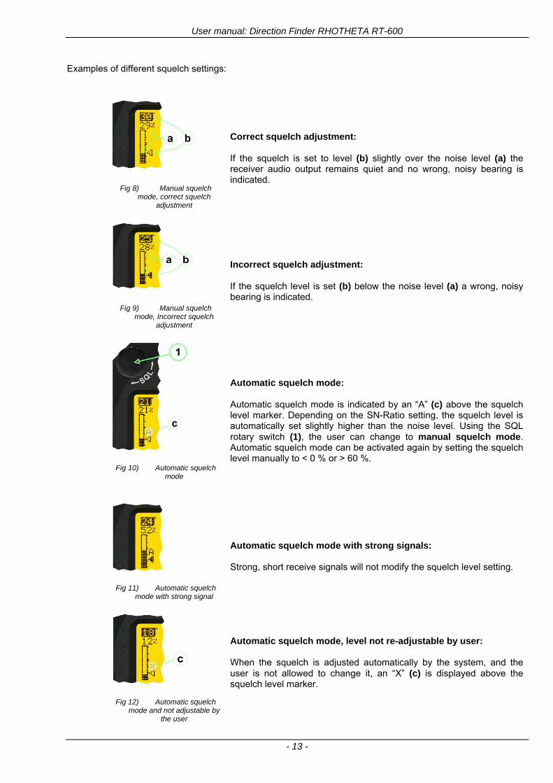
User manual Direction Finder RHOTHETA RT-600
- 13 -
Examples of different squelch settings
Fig 8) Manual squelch mode correct squelch
adjustment
Correct squelch adjustment If the squelch is set to level (b) slightly over the noise level (a) the receiver audio output remains quiet and no wrong noisy bearing is indicated
Fig 9) Manual squelch mode Incorrect squelch
adjustment
Incorrect squelch adjustment If the squelch level is set (b) below the noise level (a) a wrong noisy bearing is indicated
Fig 10) Automatic squelch mode
Automatic squelch mode Automatic squelch mode is indicated by an ldquoArdquo (c) above the squelch level marker Depending on the SN-Ratio setting the squelch level is automatically set slightly higher than the noise level Using the SQL rotary switch (1) the user can change to manual squelch mode Automatic squelch mode can be activated again by setting the squelch level manually to lt 0 or gt 60
Fig 11) Automatic squelch mode with strong signal
Automatic squelch mode with strong signals Strong short receive signals will not modify the squelch level setting
Fig 12) Automatic squelch mode and not adjustable by
the user
Automatic squelch mode level not re-adjustable by user When the squelch is adjusted automatically by the system and the user is not allowed to change it an ldquoXrdquo (c) is displayed above the squelch level marker
User manual Direction Finder RHOTHETA RT-600
- 14 -
22 Frequency (FRQ) Selection Page The Frequency Selection (FRQ Selection) Page allows the user to select a frequency select a band and edit a frequency
Open FRQ Page
From the ldquoDFrdquo standard page activate the Page Rotary Switch in any direction to open the ldquoFRQrdquo Page for Frequency Selection
Fig 13) Open FRQ Page
Fig 14) FRQ ndash Frequency Selection Page
221 Selecting a Frequency
(1) Use the Page knob ldquoFRQrdquo again to select (recall) a frequency from
gtMEMlt four (4) memory channels gtWlt one (1) working (operating) frequency gtFIXlt fixed frequencies gtCPSARlt seven (7) COSPAS-SARSAT channel groups
(2) The actual adjusted frequency
(3) Frequency band-information
Exit Frequency dialogue
(4) Press push-button gtF1lt ldquoEXITrdquo to exit to DF mode (using the actual frequency
222 Recalling and editing frequencies from a memory channel
Recall
(1) With changing the Page rotary knob memory channels 1 4 can be selected The gtmarkerlt symbol indicates the actual memory channel
Edit
(2) MHz plusmn edits the MHz Value of the actual frequency
(3) kHz plusmn edits the kHz Value of the actual frequency
(4) F2 switches to next band
gtMHzlt and gtkHzlt directly changes and overwrites the actual selected memory frequency inside the actual band (see also 224 Editing a Frequency)
Fig 15) Recall frequency of Memory channel 3
User manual Direction Finder RHOTHETA RT-600
- 15 -
223 Recalling frequencies from fixed frequencies or CospasSarsat Channels
Fig 16) FRQ Selection Page with FIX1 selected
(1) ldquoFIXrdquo Selection range for fixed frequencies
for RT-600 Standard version for RT-600 Law Enforcement version
FIX1 ldquoEltPlbrdquo 121500 MHz international VHF air distress emergency frequency
FIX2 ldquoChnl16rdquo 156800 MHz marine VHF emergency radio channel 16
FIX3 ldquoEltMILrdquo 243000 MHz military UHF air distress emergency frequency
FIX1 ldquoEltPlbrdquo 121500 MHz international VHF air distress emergency frequency
FIX2 ldquoChnl16rdquo 156800 MHz marine VHF emergency radio channel 16
FIX3 ldquoLE(USA)rdquo 173xxx MHz LoJack Recovery System
FIX4 ldquoETSSTDrdquo 216487 MHz ETS standard frequency
FIX5 ldquoETSUCVrdquo 216512 MHz ETS ucover frequency
(2) ldquoCPSARrdquo Selection range for Cospas Sarsat channel groups
CPSAR1 ldquo022-028rdquo 406022 hellip 028 MHz Channel A B C
CPSAR2 ldquo031-037rdquo 406031 hellip 037 MHz Channel D E F
CPSAR3 ldquo040-043rdquo 406040 hellip 043 MHz Channel G H
CPSAR4 ldquo046-052rdquo 406046 hellip 052 MHz Channel I J K
CPSAR5 ldquo055-061rdquo 406055 hellip 061 MHz Channel L M N
CPSAR6 ldquo064-070rdquo 406064 hellip 070 MHz Channel O P Q
CPSAR7 ldquo073-076rdquo 406073 hellip 076 MHz Channel R S
User manual Direction Finder RHOTHETA RT-600
- 16 -
224 Editing a Frequency
While on the FRQ SELECTION Page the user can directly edit the frequency displayed
Fig 17) FRQ Selection Page before frequency editing
(1) gtMHzlt Rotary switch for direct adjustment of the displayed MHz range inside the actual band
(1 x step = 1 MHz adjustment)
(2) gtkHzlt Rotary switch for changing the displayed kHz frequency according to the actual band frequency grid (as example 8333 kHz at the VHF airband)
(3) gtF2lt Adjustment of the next available band (see next page gtgt Selecting a Frequency Band)
Fig 18) FRQ Selection Page after frequency editing
If the selected and marked frequency is not one of the MEM [14] channels then the changed frequency is automatically stored in the work frequency WorkFRQ channel
User manual Direction Finder RHOTHETA RT-600
- 17 -
225 Selecting a Frequency Band
While on the FRQ Selection Page each available band can be selected by pressing F2 BAND
(1) Press push button F2 BAND for
switch over to the next band
(2) Designation of actual selected band
(3) Max frequency limits of the actual selected band (depends on wide band options)
Fig 19) FRQ Selection Page (bands)
Frequency bands availability depends on the system version (A LE) and its wide band options (F1 to F4) These optional wide bands are available if ordered in addition to the default bands Here is a listing of DEFAULT and OPTIONAL bands available with each version of the system RT-600 (STANDARD) Listing of bands
Default bands available OPTIONAL extended bands available
Band designation Frequency limits Option Designation Frequency limits
VHF Emergency Band 118000 hellip 124000 MHz gt F1 VHF Air Band 118000 hellip 136992 MHz
VHF Marine Band 154000 hellip 163000 MHz gt F2 Extended VHF Marine 137000 hellip 224995 MHz
UHF Emergency Band 240000 hellip 246000 MHz gt F3 UHF Air Band 225000 hellip 399975 MHz
COSPAS SARSAT 400000 hellip 406092 MHz
UHF FM Band 406100 hellip 410000 MHz gt F4 Additional UHF FM 406100 hellip 470000 MHz
RT-600 (Law Enforcement) Listing of bands
Default bands available OPTIONAL extended bands available
Band designation Frequency limits Option Designation Frequency limits
VHF Emergency Band 118000 hellip 124000 MHz gt F1 VHF Air Band 118000 hellip 136992 MHz
VHF Marine Band 154000 hellip 163000 MHz gt F2 Extended VHF Marine 137000 hellip 163000 MHz
LoJack 164000 hellip 174000 MHz
ETS 216000 hellip 220000 MHz
COSPAS SARSAT 400000 hellip 406092 MHz
User manual Direction Finder RHOTHETA RT-600
- 18 -
23 Direction Finder (DF) Mode Direction Finder (DF) mode is generally used to display all valid information processed by the DF from the signal received from a target transmitter The amount and kind of information displayed by the DCU depends on the type and content of the signal received and processed by the DF Simple signals such as the analog sweep-tone modulation received from a SAR beacon (ELT PLB EPIRB PDD) on 121500 MHz allow displaying only basic bearing information while digital signals such as COSPAS-SARSAT and LOJACK allow displaying more information for ex beacon IDs GPS coordinates codes VLUs etc
231 Operating Elements in DF Mode
Fig 20) Operational Elements in DF Mode
This picture shows the DCU operating in DF Mode on the international emergency frequency 121500 MHz
with an active signal being received (1) gtFREQUENCYlt Rotary switch activates the ldquoFRQrdquo frequency page for changing and selecting the
active frequency The last selected frequency remains stored after switching offon the device The selected frequency is shown on the graphic display bottom right Above additional information for the selected frequency is displayed The use of the rotary switch activates a sub-page Please refer to the Frequency Selection section for details
(2) gtVOLUMElt Rotary switch to adjust the audio output level The volume of a linked external speaker or amplifier can be adjusted in a range from 0 (off) to 99 (maximum loudness) The selected volume is shown in the bottom left corner of the graphic display The volume remains stored after switching offon the device
(3) gtSquelch Levellt adjusts the squelch level The squelch level has to be above the receiving level without signal (noise) Only signals above the squelch level are audible in the loudspeaker and used by the direction finder for bearing indication The gtSQLlt rotary switch allows to select the squelch threshold ie a minimum signal strength of an incoming signal to be processed The current settings on a signal level scale from 0 to 60 is shown in bright letters on dark background below the SQL rotary switch and as an arrow beside the signal Strength Bar-Graph
(4) The gtCLRlt Push-button is used for erasing the internal bearing value averaging store and the Last Signal Timer To activate this function the push-button has to be hold down for a minimum of circa two seconds The sophisticated averaging store increases bearing precision and enables at all an usable
User manual Direction Finder RHOTHETA RT-600
- 19 -
bearing display in case of bad receiving signals (if there is a far away transmitter andor temporary complete loss of a receiving signal) Caused by the averaging procedure a drag error may occur which might be disturbing the bearing indication after a quick change of course of the aircraft or vehicle In this case the indicated bearing value lags by the real bearing value for about two seconds (for very weak signals even longer) By pressing this push-button after a quick change of course the display will show the new bearing value without drag error Additionally the F1CLR Push-Button is used to activate specific functions high-lighted in the menu below the button by pushing it for a short time (here as example ldquoSCANrdquo starts scanning the actual air band)
(5) gtSTORElt push-button Without function except if a special function is high-lighted in the menu line of the display
(6) gtREPEATlt Push-button when pressed and hold for min 3 sec the last valid bearing value with corresponding receiving level is displayed
232 Standard Display in DF Mode
Fig 21) DF Mode
(1) gtRelative Bearing valuelt by means of a sophisticated averaging procedure a steady display is
accomplished as graphic display and as text in the range of 0deghellip 359deg (0deg corresponds to bearing direct ahead)
(2) gtSpreadlt maximum deviation of un-averaged bearing values This is an indicator of bearing quality The wider the range between the directions of maximum deviation the worse the received signal is As a result of the excellent averaging procedure even with a spread of 45deg good bearing results are achieved
(3) gtReceiving levellt (field strength) of the signal as a relative percentage value visualized as bar-graph indication and as decimal value Even without a received signal a certain noise level may be displayed
(4) gtSquelch levellt (independently adjustable and stored for each frequency band) Squelch level is indicated as marker at the Signal Strength Bar-Graph or as direct relative level value A usable bearing analysis can only be achieved if the squelch level is above the noise level (without received signal) If the antenna unit is placed close a heavily disturbing electronic devices the squelch level has to be raised thus making the direction finder being less sensitive In receive modes where the squelch level is set automatically an ldquoArdquo above the marker indicates the ldquoAutosquelchrdquo functionality
(5) gtLast Signallt timer showing the time since a signal has been received for the last time (ie since a signal has been stronger than the squelch level) Values are ldquominutes secondsrdquo
User manual Direction Finder RHOTHETA RT-600
- 20 -
233 Special Options in COSPAS-SARSAT DF Mode
Especially for the use together with beacons transmitting a data signal according to COSPAS-SARSAT specifications in the 406-MHz-Band special functionalities and pages are being provided After selection of a COSPASSARSAT Frequency (Refer to the chapter ldquoFrequency selection Pagerdquo) the bearing page provides additional information and operating options
Fig 22) Operational Elements and Display in COSPAS-SARSAT DF Mode
(1) gtAuto Squelchlt indication indicating that the squelch level is set automatically to be close to the noise
floor It is recommended to always use the Auto Squelch during COSPAS-SARSAT operation This can be achieved by manually selecting 0 (lowest possible value) or 60 (highest possible value) as squelch level During COSPAS-SARSAT-Operation this will force the automatic setting of the level
(2) gt121500lt menu option The COSPAS-SARSAT signal in the 406 MHz band is transmitted only every 50 seconds in form of a short data burst of 440 or 520 ms approaching the transmitter it will be received earlier than the 121500 MHz continuous signal due to its high transmitter power However in a lower distance to a transmitter bearing on 121500 MHz is faster thanks to the continuous or rapidly intermittent signal The 121500 MHz menu option allows a direct switch-over to 121500 MHz Direct return back from 121500 to the COSPAS-SARSAT band is possible from the 121500 MHz bearing Window in COSPAS-SARSAT mode Please refer to the chapter ldquo121500 MHz bearing Window in COSPAS-SARSAT moderdquo for details
(3) gtDecodelt menu option allows to open the COSPASSARSAT Decode sub-page by shortly pushing the F2 push-button above the menu option
(4) gtFrequency rangelt indication COSPAS-SARSAT is using a channel spacing of 3 kHz for its beacons Due to the internal architecture of the direction finder it is possible to receive more than one channel in the same time Thus frequency steps of the direction finder are 833 kHz instead of 3 kHz The receive frequency covered by the current receive frequency setting is shown in the display line above the receive frequency indication
Important If the exact frequency of the COSPAS-SARSAT beacon is unknown it is strongly recommended to use the COSPAS-SARSAT scanning functionality in order to detect the correct frequency (Refer to the chapter ldquoFrequency selection Pagerdquo amp ldquoCOSPAS-SARSAT Scan Moderdquo)
User manual Direction Finder RHOTHETA RT-600
- 21 -
234 COSPAS-SARSAT Decode Window
The COSPAS-SARSAT Decode Window allows decoding incoming COSPAS-SARSAT data messages Only while this decode window is activated the decoding is possible An already received COSPAS-SARSAT puls while DF bearing mode was activated can not be used for decoding afterwards In this case the user has to wait while this decode window is active for the next transmitted puls approx 50 sec later
Fig 23) COSPAS-SARSAT Beacon Information Page
(1) gtExitlt push button (F1 button) allows to exit the decode window and switch back to the COSPAS-
SARSAT DF Mode page
(2) gtSARSATlt in the upper right corner of the display indicates that the COSPAS-SARSAT decode function is activated
(3) gtCountrylt displays the COSPAS-SARSAT Country Code coded into the received data message
(4) gtLast Signallt time since the last COSPAS-SARSAT message has been received in minutes secondsrsquo format
(5) gtPositionlt field showing in case of location protocols being used by the beacon the encoded GNSS position data (latitude longitude) transmitted by the beacon
(6) gt15-HEX-IDlt 15-HEX-ID of the beacon in hexadecimal format
(7) gtData stringlt of the bits 25 to 112 of the COSPAS-SARSAT data burst in case of short messages and bits 25 to 144 in case of a long message format The last 8 Hex Values are separated by a blank Bit- and Frame-synchronization hex values (Bits 1 to 24) are suppressed to increase the readability of the data message
(8) gtXlt sign to indicate that the Squelch is controlled by the antenna unit for optimum sensitivity The user has no access to the Squelch setting
User manual Direction Finder RHOTHETA RT-600
- 22 -
235 Tracking 121500 MHz while in COSPAS-SARSAT Mode
While in COSPAS-SARSAT DF Mode the user can switch to 121500 MHz in order to track the beacon in VHF If a valid signal is not received in 121500 MHz the user can switch back to the last active COSPAS-SARSAT channel (406 MHz frequency) being tracking previously
Fig 24) Tracking 121500 MHz while in COSPAS-SARSAT Mode
Differences are (1) gt406xlt press F1 to switch back to the last
COSPAS-SARSAT channel (406 MHz frequency) being tracking previously
(2) gt121500 MHzlt Actual frequency being tracked
User manual Direction Finder RHOTHETA RT-600
- 23 -
236 COSPAS-SARSAT Scan Mode
If the COSPAS-SARSAT Scan Mode has been selected at the frequency selection page ldquoFRQrdquo the COSPAS-SARSAT channels as selectable manually from the Frequency Selection Page are scanned After reception of a COSPAS-SARSAT Signal the scanning is stopped at the received frequency Due to the fast scanning ndash the complete COSPAS-SARSAT sub-band is scanned within less than 400 ms ndash detection of a receivable COSPAS-SARSAT signal is possible within one COSPAS-SARSAT repetition cycle
Fig 25) FRQ Selection Page with SCN COSPAS-SARSAT Scan Page selected
At the frequency selection page an active COSPAS SARSAT scanning can be stopped by de-activating it with the rotary button (1) While the scanning is active it is also possible by pressing gtF1lt ldquoEXITrdquo to switch back to the DF pagehellip
Fig 26) DF page with active COSPAS-SARSAT Scan Mode at the DF page
(1) gtSCANlt flashing indication notifying the user that the equipment is operating in scan mode
(2) Frequency display indicating the COSPAS-SARSAT scanning frequency range
(3) gtXlt sign showing that squelch settings are controlled autonomously by the receiver
Scan mode can be left by pressing gtF1lt ldquoSTOPrdquo
User manual Direction Finder RHOTHETA RT-600
- 24 -
237 Marine Ship Scan Mode
Fig 27) DF Mode FRQ = 156800 MHz F1 for scan function
If the active frequency (2) is within the VHF Marine Band a fast scan of all ship channels is possible by pushing gtF1lt ldquoSCAN (1) In this scanning mode all marine channels 1 to 88 (156025 to 157450 MHz) are scanned continuously until a signal is received To offer the best monitoring functionality for the user also signals between to channels (4) are detected (scanning without gap) In order to prevent the scan to stop on noisy frequencies it is recommended to start scanning with high squelch settings You can reduce the squelch level in steps until the scan stops on a noisy frequency for the first time Then increase the squelch level slightly This will result in the highest possible scan sensitivity and avoiding noisy channels due to RF disturbances sometimes generated by other equipment in own aircraft
Fig 28) DF Mode active scanning in process
The scanning is stopped by pressing gtF1lt ldquoSTOPrdquo (3)
User manual Direction Finder RHOTHETA RT-600
- 25 -
24 Law Enforcement Operation Law enforcement special ops and other organizations use the RT-600 LE (LAW ENFORCEMENT) version instead of the RT-600 A (STANDARD) version One of the reasons is that the LE version features scanning and tracking of signals like LoJack and ETS as well as signals in the 216000 MHz ndash 220000 MHz band such as medical beacons wristankle transmitters cashasset recovery ldquotagsrdquo etc However the LE version shares many functions in common with the A version such as scanning and tracking in the AIR band COSPAS-SARSAT band etc
241 Power-On procedure
The power-on procedure is the same as described in 211
(1) System Version ldquo(L)rdquo for LAW ENFORCEMENT version
Fig 29) STARTUP Screen (see 211 for details)
242 LoJack Scan Mode Start scanning for a VLU Code
For the convenience of Law Enforcement and other special ops users who frequently engage in tracking SVRS (Stolen Vehicle Recovery System) signals such as LoJack (LoJack Corp FCC 9020 Part 2 SVRS) RHOTHETA has optimized the power-on procedure of the RT-600 LE version so that right after the STARTUP screen the unit displays automatically the LoJack Scan Mode page to start immediately scanning for a valid VLU (Vehicle Location Unit) code without pressing any key
Fig 30) LoJack Scan Mode unit is scanning for a LoJack VLU Code
(1) gtscan LoJacklt DF is scanning for any new LoJack VLU Code
(2) gtEXITlt press F1 to exit and switch directly to DF Mode
User manual Direction Finder RHOTHETA RT-600
- 26 -
243 LoJack Scan Mode from any other page
While operating on any page other than the LoJack Scan page the user can switch directly to LoJack Scan Mode by pressing Hotkey F2 for 2 secs
(1) press Hotkey F2 for 2 secs to switch to the LoJack Scan page
Fig 31) Hotkey F2
User manual Direction Finder RHOTHETA RT-600
- 27 -
244 Manual activation of LoJack Scan Mode
(1) select the LoJack frequency (see also Frequency Selection Page)
(2) press F1 to switch back to the DF MODE
Fig 32) FRQ Selection Page FRQ = LoJack BAND = LoJack (164-174 MHz)
While in DF MODE with adjusted LoJack frequency the user can switch directly to the LoJack Scan by pressing gtF1lt ldquoSCANrdquo
(1) press F1 SCAN to switch to the LoJack Scan page
(2) still no LoJack ID filter used (ID=off) all transmissions are received on the active frequency as example also unwanted tower pulses
Fig 33) DF Mode with LoJack filter OFF
User manual Direction Finder RHOTHETA RT-600
- 28 -
245 Receiving and accepting a new VLU Code
While in LoJack Scan Mode waiting for a VLU Code if a new VLU Code is displayed the user can accept it and switch directly to DF Mode by pressing F2
(1) a new LoJack VLU Code (0001A) has been received
(2) press F2 to accept the new VLU Code (0001A) and switch to DF MODE page with the LoJack filter activated to track only 0001A
Fig 34) LoJack Scan Mode with new VLU Code received
246 Entering a new VLU Code manually
While in LoJack Scan Mode the user can enter a LoJack VLU code also manually
(1 2 3) use the SELECTplusmn and plusmnVALUE knobs to enter a new LoJack VLU Code active ID (0001A)
(4) Press F1 to accept the new VLU Code and switch to DF Mode with the LoJack filter ON to track only 0001A
Fig 35) LoJack Scan Mode with new VLU Code entered manually
User manual Direction Finder RHOTHETA RT-600
- 29 -
247 Tracking one VLU Code while monitoring new VLU Codes
While on DF Mode and tracking a VLU Code (0001A) the user can turn the LoJack switch OFF with F2 also the user can start scanning all VLUs again with F1
0001A is displayed as the active VLU Code filter function is ON only 0001A is tracked
Monitoring of other VLU Codes is active in the background
(1) Press F1 to switch to the LoJack Scan Mode to scan for new VLU Codes
(2) Press F2 to switch LoJack filter OFF
Fig 36) DF Mode with active VLU Code and LoJack filter ON
248 Tracking one VLU Code and receiving a new VLU Code
While on DF MODE page and tracking VLU Code (0001A) in the background a new VLU Code is received and decoded (G2HC7)
(1) The new VLU Code is announced (NEW G2HC7)
(2) Press F1 to switch to LoJack Scan Mode to see the arrival time of G2HC7 and the possibility to change bearing to this new G2HC7
Fig 37) DF Mode with active VLU Code and announcement of new VLU Code
User manual Direction Finder RHOTHETA RT-600
- 30 -
249 Switching to a new VLU Code
While on the LoJack Scan Page tracking one VLU Code (0001A) and notified of a new VLU Code (G2HC7)
(1) press F1 to continue tracking 0001A
(2) press F2 to start tracking G2HC7
(3) Time elapsed since G2HC7 was last received
(4) Time elapsed since 0001A was last received
If F1 is pressed for 2 sec the indicated VLU Code (G2HC7) and ID (0001A) are deleted
Fig 38) LoJack Scan Page with one active VLU Code and one new VLU Code
2410 ldquoBlockingrdquo function of one LoJack VLU Code
The LoJack scan page can also be used to ldquoblockrdquo one unwanted LoJack VLU ID signal by separating the adjusted active ID from any other received LoJack VLU signal This is done by muting the audio (see example below) when a LoJack signal with VLU code ldquo0001Ardquo is received gtgt Any new VLU Code (active LoJack signal) - except for 0001A ndash will be displayed on the top row and generate the audible beep tone
Fig 39) LoJack Scan Page with one active VLU Code and audio OFF
Tip ldquoBlockingrdquo is an important tool for practical missions As example a stolen vehicle with VLU ID ldquo0001Ardquo was tracked in the DF bearing mode The mission
is completed but the VLU is normally still transmitting With the settings above only new VLU signals except the now unwanted ldquo0001Ardquo are audible and displayed in the upper (scan LoJack hellip for new VLU) box
User manual Direction Finder RHOTHETA RT-600
- 31 -
2411 Tracking in the 216 to 220 MHz band
The RT-600 features scanning and bearing functionality in the 216000 MHz to 220000 MHz band The 216000 MHz ndash 220000 MHz band contains frequencies and signals used by special services and tracked by law enforcement special ops and similar organizations These are some of the frequencies and services in this band
CFR 90259 tx 216000 MHz to 220000 MHz
Low Power Radio Service (LPRS) tx 216000 MHz to 217000 MHz
Medical beacons Project Lifesaver tx wristankle tx 213000 MHz to 216000 MHz
ETS tx stolen cashasset recovery tx ldquobaitrdquordquotagrdquo tx 216000 MHz to 220000 MHz tx = transmitter(s) However any future or current user of the Rhotheta RT-600 must be aware that tracking signals on the frequencies listed above may be challenging and even frustrating due mostly to negative factors in some of the transmitters
bull Very low RF power output
bull Inefficient antennas
bull Battery-powered devices with a ldquolow batteryrdquo condition
bull Devices worn or located in conditions of poor RF propagation
bull Devices with channel spacing different than the one specified for the RT-600
These factors can make it very difficult for the DF to receive the signal andor display an accurate bearing Disclaimer For the reasons explained above and even though the RT-600 features top performance in its class RHOTHETA does not offer - and is not to be held responsible for - any guaranteed minimum range or distance to a transmitter in this band
25 Setup Edit Page System settings are displayed in the setup page The functions described in this section should be used by trained personal only
Fig 40) Accessing the Setup Page
The setup page can be accessed by holding down the gtCLRlt (1) and gtREPlt (2) buttons simultaneously and in the same time performing a left-hand turn on the gtPagelt rotary switch (3)
User manual Direction Finder RHOTHETA RT-600
- 32 -
Fig 41) Setup Page
(1) gtStorelt push-button must be pressed in parallel if a value of a setting shall be modified If a value can
be modified the background stops to blink
(2) gtSelectlt rotary switch used to scroll through the menu options The value of the actually activated menu option is high-lighted with dark background and blinking
(3) gtValuelt rotary switch used to change values in menu options (gtStorelt (1) has to be pressed in parallel if a value shall be modified)
(4) gtSN-Ratiolt menu option representing the necessary Signal-To-Noise-Ratio (Difference between signal and noise level) used as criterion for the automatic squelch function Please refer to the chapter ldquoSquelch Operationrdquo for details Default value is 60 dB
(5) gtMounting Positionlt menu option to select Top- or Bottom-Mounting of the DF antenna In case of rooftop installation (eg on land vehicles) ldquoToprdquo shall be selected In case of bottom-down (upside-down) installation (eg on a helicopter) ldquoBotrdquo shall be selected If this option is not selected correctly all bearing values will be mirror-inverted
(6) gtBearing Offsetlt menu option to include a constant offset correction to the bearing indication Bearing values in degrees will be changed according to the offset value
(7) gtMaximum External Dimming Voltage for Legendslt menu option which sets the upper limit of the dimming input voltage for the legends-panel Range=[15 hellip 28]V
(8) gtMinimum External Dimming Voltage for Legendslt menu option which sets the lower limit of the dimming input voltage for the legends-panel Range=[15 hellip 28]V
(9) gtPagelt rotary switch to be turned right-hand to go back to the Direction Finder page A left-hand turn on this rotary switch will show up an additional service page with debug information used for system checks
(10) gtExtended Seriallt It is possible to enable or disable the extended serial data protocol Only of interest if serial data is used by any connected control units like moving maps or computers For detailed information see (Serial interface data protocol (short description)gt at page 46) If there are compatibility problems with already existing older remote control software it is recommended to switch OFF the extended serial data protocol
User manual Direction Finder RHOTHETA RT-600
- 33 -
3 Error messages If an internal error of the device is recognized a corresponding flashing error message will be shown in the DF pages
Fig 42) Error Messages
(1) Error message including error code (in brackets)
(2) Short description of the indicated error
In case of coincidence of various errors the error with the highest priority will be displayed
Error message Error location Reason
Error (12) VOLTDU
Main voltage supply Main Voltage input too low ( 100 V)
Error (11) NO AU
Connection antenna display or Antenna Unit
No serial data (RS485) from Antenna Unit No or damaged connection between antenna and display or damaged antenna unit
Error (10) BAD AU
Connection antenna display
Incompatibility or bad data connection between display and antenna
Error (9) BAD RU
Remote Unit Incompatibility or bad data connection between display and external serial Remote Unit or PC
Error (8) VOLTAU
Antenna Unit Voltage supply at Antenna Unit too low ( 90 V) Main voltage supply too low or considerable drop of voltage between display and antenna
Error (7) BAD DCU
Connection Display Antenna
Incompatibility or bad data connection between antenna and display
Error (6) NO DCU
Connection Display Antenna
No serial data from Display Control Unit to Antenna Unit
Error (5) PLL ERR
antenna Error in synthesizer-oscillator of receiver in Antenna Unit
Error (4) FRQ+OFS
received transmitter Received frequency too high (more than 6 KHz error of transmitter)
Error (3) FRQ-OFS
received transmitter received frequency too low (more than 6 KHZ error of transmitter)
Error (2) DECODE
radio distance transmitter DF
Data Bits of decoded signal (COSPAS-SARSAT or LoJack) defective
Error (1) DATARNG
Incompatibility of data DCU AU
Protocol data bytes out of valid range
Error (0) NO REC
Antenna Unit receiver
Receiver board defective
User manual Direction Finder RHOTHETA RT-600
- 34 -
4 Installation
41 Antenna unit A convenient position of the monopole bearing antenna is crucial for good bearing results The antenna needs an effective ground connection to the body of the aircraft or to the roof of the vehicle If there is no metallic mounting surface available a metallic sheet or similar (net) with connection to ground has to be applied first between vehicle-body and antenna In this hatched area the antenna touches the body ofthe vehicleaircraft In order to obtain a good groundconnection the surface of the body should be bared(Measuring unit [mm])
8 x holes for mounting the antenna unit to the
vehicle aircraft
Fig 43) Antenna Mounting Drawing
User manual Direction Finder RHOTHETA RT-600
- 35 -
411 Influence of antenna location and environment on the bearing accuracy
Recommendations concerning the practical antenna unit location on helicopters and airplanes
The bearing accuracy of the direction finder antenna unit is severely influenced (comparable to an airspeed sensor) by the environment For comparison a perfect high quality speed sensor will not indicate the true airspeed if this sensor is interfered by strong turbulences The direction finder antenna unit acts as a sensor for electromagnetic waves In the near field of this antenna unit any conductive (eg metallic) obstacle will influence the incoming wave field and create reflections which decrease the bearing accuracy These are general physical limitations concerning all types of direction finder systems To achieve the best bearing results it should be considered that the antenna unit is installed as far away as possible from any other vertically polarized conductive structure If possible there should be no reflectors within an area of 2-3 feet around the antenna unit In this worst case example the direction finder will not work properly
Fig 44) Antenna Installed in a Bad Location
In this example the antenna unit is located too close to the cable cutter of the helicopter This cutter will produce strong reflections especially as the length is equal to Lambda4 within the VHF airband
User manual Direction Finder RHOTHETA RT-600
- 36 -
Examples of properly installed direction finder antenna units
Fig 45) Antenna Installed in Good Locations
User manual Direction Finder RHOTHETA RT-600
- 37 -
42 Display and Control Unit
The display control unit may be mounted into a front panel by the means of this mounting drawing
Fig 46) DCU Mounting Drawing
(all dimensions in [mm]) To install or uninstall the display control unit perform the following steps (1) Remove the cover caps of the four rotary switches
(2) Loose the screws visible below the position of the cover caps
(3) Remove the plastic button from the axis of the four rotary switches
(4) Mount dismount the display control unit
(5) Re-install the plastic buttons on the axis of the four rotary switches
(6) Fix the screws so that the plastic buttons are fixed on the axis
(7) Re-install the cover caps on the four rotary switches
User manual Direction Finder RHOTHETA RT-600
- 38 -
43 System Interconnect Wiring Diagram (Also refer to chapter ldquoTechnical Datardquo for details)
Fig 47) System Interconnect Wiring Diagram
6-pol Amphenol plug femalePTG06SE10-6S(SQ)
max length of cable 20 m 9-pol Sub-D plug (femalemale)
User manual Direction Finder RHOTHETA RT-600
- 39 -
5 Technical Data
51 Electric features
Method of bearing Doppler-principle (3 kHz rotational frequency right left rotation)
Bearing accuracy1 plusmn 5deg RMS
Internal resolution 1deg
Bearing Sensitivity VHF AirEmergency le 25 μVm (typical)
VHF Marine le 25 μVm (typical)
UHF Emergency and ETS le 4 μVm (typical)
COSPAS-SARSAT le 4 μVm (typical)
LoJack Decoding (50 Message Error Rate) and bearing le 5 μVm (typical)
Frequency stability plusmn 20 ppm (Δff = plusmn210-6)
Reception frequencies
SAR version (Standard)
Frequency Options
VHF Emergency Band 118000 to 124000 MHz (833 kHz steps AM)
VHF Marine Band 154000 to 163000 MHz ( 500 kHz steps FM) (channel 16 selectable via channel no)
UHF Emergency Band 240000 to 246000 MHz (2500 kHz steps AM)
UHF FM Band 406100 to 410000 MHz ( 500 kHz steps FM)
COSPAS-SARSAT 400000 to 406092 MHz Including 406022 to 406076 MHz (Channel A S)
F1 VHF Air Band 118000 to 136992 MHz
F2 extended VHF Marine Band 137000 to 224995 MHz
F3 extended UHF Air Band 225000 to 399975 MHz
F4 additional UHF FM Band 406100 to 470000 MHz
Reception frequencies
LAW Enforcement version
Frequency Options
VHF Emergency Band 118000 to 124000 MHz (833 kHz steps AM)
VHF Marine Band 154000 to 163000 MHz (500 kHz steps FM) (channel 16 selectable via channel no)
LoJack 164000 to 174000 MHz (125 kHz steps FM)
ETS 216000 to 220000 MHz (10125 kHz AM)
COSPAS-SARSAT 400000 to 406092 MHz Including 406022 to 406076 MHz (Channel A S)
F1VHF Air Band 118000 to 136992 MHz
F2 extended VHF Marine Band 137000 to 163000 MHz
COSPAS-SARSAT fast scan mode
Full automatic detection of any active COSPAS-SARSAT channel A to S within 400 ms
COSPAS-SARSAT decoding
Reception and decoding of COSPAS-SARSAT data signal (112 or 144 bit) specified according to COSPAS-SARSAT
LoJack decoding Selectable LoJack ID display and selective active filtering
Special scanning modes
complete maritime ship band scanning within 3 s (channel 01 hellip 88 also frequencies between 2 channels are included)
1With undisturbed wave field and sufficient field strength Measuring by changing the angle of incidence with the antenna rotating on a revolving table in order to eliminate environmental influences on the results No modulation
User manual Direction Finder RHOTHETA RT-600
- 40 -
Bearable modulation A3E F3E A3X (ELT-modulation) F1D G2D COSPAS-SARSAT Bearing largely independent of modulation
Polarization Vertical
Polarization error 5deg at 60deg field vector rotation
Garbling cone Ca 30deg to the vertical
Time of response2 50 ms (with sufficient reception field strength)
LC-graphic display 128 x 64 pixels supertwist transflective extended range of temperature dark-blue display on yellow-green background background light Freely adjustable (exponential) dimming of brightness
NVG cockpit design Fully compatible NVIS Green B display Control Unit optional
Operating voltage 275 V nominal 12 V to 35 V DC
Current consumption LCD-background light Off max 500 mA (12 V DC) max 250 mA (24 V DC)
LCD-background light 100 max 750 mA (12 V DC) max 350 mA (24 V DC)
LCD-background light 100 max 900 mA (12 V DC) with NVG Option max 400 mA (24 V DC)
Audio out For external speaker approx 2 W (4 Ω)
Serial data interface Serial interface RS-232 (9600 baud 8 data bits 1 stop bit no parity)
2Very weak signals can considerably increase the time of response
User manual Direction Finder RHOTHETA RT-600
- 41 -
52 Interface External connections (optional at Sub-D 9-pol Male connector)
Dimming
Pin 8
external voltage input for variable dimming of legends
(optional)
Analog input signal for variable control of the legends illumination Input voltage range is freely adjustable in the range of 15 hellip 28 V in the setup menu Refer to chapter ldquoSetup Pagerdquo Default setting 8 hellip28 V (8 V = Off 28 V = max dimming for legends)
Input Impedance gt 50 k
Pin 6 night status line for LCD
dimming (optional)
Low-active (as example switch to ground) At input voltage lt 25 VDC the LCD dimming operates in nightNVG mode Maximum brightness ca 4 of daydefault mode brightness
Input Impedance gt 50 k
Pin 4 NVG status line for LCD
dimming (optional)
Low-active (as example switch to ground) At input voltage lt 25 VDC the LCD dimming operates in nightNVG mode Maximum brightness ca 4 of daydefault mode brightness
Input Impedance gt 50 k
AudioLF
Pin 7 Audio output signal
AC coupled voltage source with very low inner resistance Maximum output voltage ca 8 VPP = 283V RMS at maximum Volume Maximum output power ca 2 W with 4 speaker
If a headphone is connected ([32hellip600] 100mW) we recommend using a resistor (18 025 W) between audio output and headphone to prevent damage of the headphone
Serial interface RS232 (9600 baud 8 data bits 1 stop bit no parity)
Pin 3 TXD Serial output (ca plusmn10 V)
Pin 2 RXD Serial input (ca plusmn10 V)
User manual Direction Finder RHOTHETA RT-600
- 42 -
53 Mechanical features
Temperature range
Display Control Unit permissible operating temperature3 -20 degC +60 degC permissible storage temperature -30 degC +80 degC
Antenna Unit permissible operating temperature3 -40 degC +60 degC permissible storage temperature -55 degC +80 degC
Protective system Antenna Unit IP 67
Weights Display Control Unit 250 g Antenna Unit 2000 g
Dimensions Display Control Unit 82 mm x 82 mm x 43 mm (width x height x depth) Antenna Unit 270 mm x 185 mm
Fig 48) DCU Mechanical Drawing (all dimensions in [mm])
3 For temperatures lower than ndash10deg C a warm-up period of 15 min should be allowed
User manual Direction Finder RHOTHETA RT-600
- 43 -
Fig 49) AU Mechanical Drawing (all dimensions in [mm])
User manual Direction Finder RHOTHETA RT-600
- 44 -
6 Appendix
61 Frequency Ranges
User manual Direction Finder RHOTHETA RT-600
- 45 -
62 Frequencies of channels on maritime band (only for standard [A] version) Frequency-range of the RT-600 in the maritime band 156000 MHz 162025 MHz
Channel No frequency (ship - station) Frequency (coast - station)
1 156050 MHz 160650 MHz 2 156100 MHz 160700 MHz 3 156150 MHz 160750 MHz 4 156200 MHz 160800 MHz 5 156250 MHz 160850 MHz 6 156300 MHz 160900 MHz 7 156350 MHz 160950 MHz 8 156400 MHz 9 156450 MHz
10 156500 MHz 11 156550 MHz 12 156600 MHz 13 156650 MHz 14 156700 MHz 15 156750 MHz 16 156800 MHz 17 156850 MHz 18 156900 MHz 161500 MHz 19 156950 MHz 161550 MHz 20 157000 MHz 161600 MHz 21 157050 MHz 161650 MHz 22 157100 MHz 161700 MHz 23 157150 MHz 161750 MHz 24 157200 MHz 161800 MHz 25 157250 MHz 161850 MHz 26 157300 MHz 161900 MHz 27 157350 MHz 161950 MHz 28 157400 MHz 162000 MHz 60 156025 MHz 160625 MHz 61 156075 MHz 160675 MHz 62 156125 MHz 160725 MHz 63 156175 MHz 160775 MHz 64 156225 MHz 160825 MHz 65 156275 MHz 160875 MHz 66 156325 MHz 160925 MHz 67 156375 MHz 68 156425 MHz 69 156475 MHz 70 156525 MHz 71 156575 MHz 72 156625 MHz 73 156675 MHz 74 156725 MHz 75 156775 MHz 76 156825 MHz 77 156875 MHz 78 156925 MHz 161525 MHz 79 156975 MHz 161575 MHz 80 157025 MHz 161625 MHz 81 157075 MHz 161675 MHz 82 157125 MHz 161725 MHz 83 157175 MHz 161775 MHz 84 157225 MHz 161825 MHz 85 157275 MHz 161875 MHz 86 157325 MHz 161925 MHz 87 157375 MHz 161975 MHz 88 157425 MHz 162025 MHz
User manual Direction Finder RHOTHETA RT-600
- 46 -
63 Serial interface data protocol (short description)
631 General
Interface parameters RS232 9600 Baud 8 databits 1 stopbit no parity LSB sent first Timing of serial data For accurate use of the serial data (even for the optional serial input commands) the correct timing is mandatory The DCU (Display Control Unit) sends out via the RS-232 Pins (see 43 System Interconnect Wiring Diagram page 38) cyclic and autonomous every approx 250300 ms a binary data stream which contains all relevant DF-bearing information The output data contains one or two blocks of binary data (see next picture with accordingly description) The optional serial input is only used if changes (as example frequency change) are done by additional remote control units
Fig 50) Timing of serial data
Serial standard output
This output data is always available and contains all relevant DF-bearing data For detailed content see page 47
Optional extended serial output
This data contains some additional information like as example CospasSarsat or LoJack decoding and ID data For detailed content see page 50 The data is only available with DCU Software [Rev ge 320] and if this optional data block is configured as ON = enabled (see Setup Edit Page point (10) )
Even to avoid compatibility problems with already existing older remote control software it is possible to disable switch off this additional data block (see Setup Edit Page point (10) )
Optional serial input
Only used for optional commands to control DCU parameters If as example the direction finder frequency is changed remotely there is send to the DCU one time this data block with the new frequency For detailed content see page 52
User manual Direction Finder RHOTHETA RT-600
- 47 -
632 Serial standard output (protocol description)
Specification serial standard output
The binary data stream with a length of 39 bytes starts with a header byte (value = hex 0xA0 as ID for DF Mode) The next bytes contain different values for status bearing information and also service The last byte is used for data stream checksum control Remark This is a binary data protocol So every byte value from 0dec hellip 255dec (0x00 hellip 0xFF) is possible Because of this it is not allowed to realize a start byte detection by the content (0xA0) The idle line detection is recommended for detection the end of message Register of databytes (for details see next page)
byte no
[0] Header = 0xA0 Id for DF Mode
[1] Number = 39 = bytes in the complete message (including header and checksumbyte)
[2] Status (1) HSB [x|x|x|x|x|x|x|x] LSB | | | | | | | --gt (0) Receiving | | | | | | ----gt (1) Squelch controlled by AU (X) | | | | | ------gt (2) Permission RL Calibration | | | | --------gt (3) Line Night | | | ----------gt (4) Line NVG | | ------------gt (5) Dimming External | --------------gt (6) Autosquelch Active ----------------gt (7) 0=Standard Version 1=LE Version
[3] Status (2) HSB [x|x|x|x|x|x|x|x] LSB | ----------------gt (7) 0=Standard 1=extended serial dataprotocol = ONactive
[45] Error (Bits[120])
[6] Actual DCU Page
[7] Volume [0hellip100]
[811] Frequency [Hz]
[12] Active Band
[13] Actual Squelchlevel [0hellip60]
[14] Audio-Line amp_NF_Test Output
[15] (Not used)
[1617] Voltage_DCU ([0hellip335]=[0 hellip 335]V
[1819] Voltage_AU ([0hellip255]=[0 hellip 255]V
[20] Temperature_AU [-68hellip+127]degC
[21] Frequency Offset [-99hellip+99]
[2225] ServiceTest values (mode dependent test values for service only)
26 (Not used reserved)
[27] Level [0hellip100]
[2829] Bearing Averaged [0hellip359]deg relative
[3031] Bearing Live_Min [0hellip359]deg relative
[3233] Bearing Live_Max [0hellip359]deg relative
[34] Test Value PS-RAM Right Rotation[0hellip178] (for service only)
[35] Test Value PS-RAM Left Rotation [0hellip178] (for service only)
[3637] (Not used reserved)
[38] Checksum is the 2rsquos complement of the modulo-256 sum of all bytes without checksum-byte [0n-1]
User manual Direction Finder RHOTHETA RT-600
- 48 -
Detailed Description of important values for practical use
Status byte [2] Receiving Bit 0 of this value (LSB) indicates signal receiving Bit 0 = 0 then no signal is received and so on no bearing is available Bit 0 = 1 then bearing is possible Bit 1 if(1) then Squelch is controlled by AU (active at modes CospasSarsat Decode CospasSarsat Scanning LoJack with Filter=ID only)
Error bytes [4hellip5] 16 bit value each set bit corresponds to the error no (Refer to the chapter Error messages) Example - 0x0000 No error - 0x0800 Bit No 11 Set ( = No AU Error)
Actual DCU Page byte [6] indicates actual operating mode of DCU 0 = Standard bearing page 1 = Frequency memory page 2 = CospasSarsat decoding page 3 = LoJack decoding page (ID edit)
Frequency bytes [8hellip11] 32 bit value actual adjusted frequency [Hz] Example - 0x073DF160 1215000000 121500 MHz
Active Band Standard Version [A] 0=VHF Airband 1=VHF Marineband sea 2=VHF Marineband coast 3=UHV Airband 4=CospasSarsat LE Version [L] 0=VHF Airband 1=LoJack 2=Lifesaver 3=ETS 4=CospasSarsat
Actual Squelchlevel byte [13] Range [0hellip60] without signal the actual squelchlevel should always be adjusted a little bit over the noise level (Refer to the chapter Squelch operation)
Level byte [27] Range [099] actual receiving level (without signal this value is equal to the noise level) If a signal is received then this value corresponds to the signal strength of this signal
Relative Bearing averaged byte [2829] 16 bit value Range [0hellip359 0xFFFF] if the value = 0xFFFF then no valid bearing is available otherwise this value contains the actual averaged bearing information in Deg [0deg359deg] Example - 0X0114 276deg bearing (= left side oriented to heading)
Bearing Live MinMax byte[3031] amp [3233] - 16 bit values Range [0hellip359 0xFFFF] Only for signal quality or additional information ndash NOT recommended for bearing indication The relative live bearing field contains the maxmin bearing in degrees without averaging The relative live bearing reacts faster than the normal relative bearing but it has not the precision of the averaged bearing The MinMax Bearing Values are calculated within a time period of approx 250 ms If they are very close together (for example ldquo124rdquo and ldquo128rdquo degrees) then the signal quality is quite good A wide span of the minmax values (for example ldquo97rdquo and ldquo162rdquo) shows very noisy but nevertheless bearable signal quality
User manual Direction Finder RHOTHETA RT-600
- 49 -
633 DCU Info output (protocol description)
Specification DCU Info output
Remark This protocol is only available while the SetupEdit page is activated at the DCU
byte no
[0] Header = 0xAF Id for DCU Info Mode
[1] Number = 39 = bytes in the complete message (including header and checksumbyte)
[2]
(see standard output) [3]
[45]
[621] Info String of 15 byteschars the string contains Information about Unit Variant Software Version and Serial No
Example Byte [318] =
|--AU ID---||Var-||---Software Version---| |-------------- Serial No---------------| [0x44][0x55][0x41][0x33][0x2E][0x33][0x30][0x3A][0x20][0x20][0x30][0x31][0x32][0x33][0x34][0x00] rsquoDrsquo rsquoUrsquo rsquoArsquo rsquo3rsquo rsquorsquo rsquo3rsquo rsquo0rsquo rsquorsquo rsquo rsquo rsquo rsquo rsquo0rsquo rsquo1rsquo rsquo2rsquo rsquo3rsquo rsquo4rsquo rsquoENDrsquo | | | | __________________ | | ________________________ | n n n | | n n n n n | (Software Version) | | (Serial No) | gt rsquoArsquo = Standard Variant gt rsquoLrsquo = Law Enforcement Variant
User manual Direction Finder RHOTHETA RT-600
- 50 -
634 Optional extended serial output (protocol description)
The data content depends on the actual mode of the direction finder To get special data the direction finder has first to be switched to the equivalent mode
COSPAS-SARSAT Decoding data
This data is only available and valid if Display Control Unit with actual software Rev ge 320 (see Power-On procedure page 10) Configuration of Extended serial = ON (see Setup Edit Page point (10) ) Direction Finder COSPAS-SARSAT decoding mode is activated by selecting the corresponding page
(see COSPAS-SARSAT Decode Window page 20 and page 21) and so on Header (byte 0 of data) = 0x91
A valid COSPAS-SARSAT decoding data protocol is always marked by the first data byte (header = 0x91) Always after receiving and decoding of a valid COSPAS-SARSAT pulse the complete data protocol with 33 bytes is send out one time
Byte No
[0] Header = 0x91 (Identification for CPSarsat decoding mode)
[1] Number of bytes - 7 if no decoded pulse is available - 33 if new pulse was received and is available
[2] Error
[3] Bit[0] - 0 =gt No new 406 MSG (decoded data) available - 1 =gt New valid 406 MSG available (Sync amp Frame Ok) Check Error Status for Bit-Errors
Bit[61] AutoSquelch Level valid range [060] ( decimal)
Bit[7] = 1 Squelch controlled by AU
[4] Signallevel of received signal valid range [099] ( decimal)
[5] Voltage of Antenna Unit Power Supply input valid range [80255] (decimal = 80 255 V DC)
[6] Temperature inside Antenna Unit valid range [-50+100] (degC signed byte value)
The following databytes are only available if a correct CPSarsat puls gets received and decoded with correct checksum
[724] 18 x Databytes complete orginal CPSarsat 406 decoded message (144 bit)
Databyte Nr [ Byte 7 ] [ Byte 8 ] [Byte9 Byte24] 406 MSG Bit Nr [1 2 3 4 5 6 7 8] [9 10 11 12 13 14 15 16] [17 144]
[25] SN-Flag valid values 0x53=rsquoSrsquo 0x4E=rsquoNrsquo 0x2D=rsquo-rsquo if no GPS data available
GPS-Position Latitude
[26] Deg valid values [090] (decimal Deg) 0xFF if no GPS data available
[27] Min valid values [059] (decimal Deg) 0xFF if no GPS data available
[28] Sec valid values [059] (decimal Deg) 0xFF if no GPS data available
[29] WE-Flag valid values 0x57=rsquoWrsquo 0x45=rsquoErsquo 0x2D=rsquo-rsquo if no GPS data available
GPS-Position Longitude
[30] Deg valid values [0180] (decimal Deg) 0xFF if no GPS data available
[31] Min valid values [059] (decimal Deg) 0xFF if no GPS data available
[32] Sec valid values [059] (decimal Deg) 0xFF if no GPS data available
User manual Direction Finder RHOTHETA RT-600
- 51 -
LoJack ID data
This data is only available and valid if Display Control Unit with actual software Rev ge 320 (see Power-On procedure page 10) Direction Finder of variant [L] Law Enforcement Configuration of Extended serial = ON (see Setup Edit Page point (10) ) Direction Finder is working with active LoJack gtID Filterlt Header (byte 0 of data) = 0x93 or 0x94
Valid LoJack ID decoding data is always marked by the first data byte (header = 0x93 or 0x94)
Byte No
[0] Header = 0x93 LoJack ID editing sub-page is selected Filter = VLU all valid and received LoJack pulses are indicated = 0x94 Lojack Decode amp DF Mode with active Filter = ID
[1] Number of bytes in the complete data stream - decimal 26 = default value
[2] Nonrelevant
[3] Bit[0] Receiving OnOff - 0 =gt No Receiving no bearing - 1 =gt new LoJack pulse received
[412] Nonrelevant
[1317] Lojack ID
Replay Code 5 x ASCII Chars ldquoNo BIOZrdquo set
Example ASCII = ldquo000R1rdquo
18 Receiver Level Out Max [099]
19
LoJack Decoder Status [07] - 0 Off - 1 Wait for Preamble - 2 Preamble Ok - 3 FlagPattern Ok - 4 Data BitError gt 1 - 5 Data Ok (No VLU) - 6 VLU Ok - 7 ID Ok (Filter=IDONLY)
[2025] Nonrelevant
Remark Only if byte no [3] bit [0] gets ldquo1rdquo (Receiving On) then an active LoJack pulse is received and so on the corresponding LoJack ID valid otherwise the LoJack ID only shows the actual adjusted LoJack Filter ID of the direction finder
User manual Direction Finder RHOTHETA RT-600
- 52 -
635 Optional serial input (protocol description)
Specification serial input (optional)
The serial input is normally used for service and maintenance only Nevertheless it is possible via this interface to remote control the actual frequency and the squelchlevel of the DF system If a valid data stream is send to the DF then the actual frequency selection at the DCU is switched to Block2 AUX0 At this memory channel the new frequency is stored and used automatically (Refer to the chapter Frequency Selection Page) If the frequency is changed (by one valid data stream) no more serial input is necessary The actual frequency can be changed again at any time by manual operation at the DCU The timing of serial input (if used) is strictly fixed The optional serial input has to take place directly after a complete serial output (max 50 ms delay time) If a new changed frequency is commanded to the DCU via this serial input interface it can take up to 1 sec of time until this new frequency is ready for operationbearing It is strictly not recommended to use the frequency remote control for any scan mode The frequency control has to be used for static frequency change only Register of databytes
byte no
[0] Header 0xC0
[1] Number of bytes in the complete message (including header and checksumbyte)
[23] (not used for normal operation any byte values allowed)
[4] Volume [0100]
[58] Frequency [Hz] (frequency is rounded to the according grid automatically)
Valid Range for Standard Version Valid Range for LE Version
118000000 hellip 123000000 [Hz] 8333 kHz 118000000 hellip 123000000 [Hz] 8333 kHz
156050000 hellip 162025000 [Hz] 5000 kHz 164000000 hellip 174000000 [Hz] 8333 kHz
201000000 hellip 215995000 [Hz] 5000 kHz
240000000 hellip 246000000 [Hz] 8333 kHz 216000000 hellip 218995000 [Hz] 12500 kHz219000000 hellip 220000000 [Hz] 10000 kHz
400000000 hellip 410000000 [Hz] 8333 kHz 400000000 hellip 410000000 [Hz] 8333 kHz
[9] Squelchlevel Manual = [0hellip60] Autosql= [ -1] Warning use only for pulsed signals (as example CpSarsat LoJack)
[10] (not used for normal operation any byte values allowed)
[11] Internal Dimming [0100]
[12] Checksum is the 2rsquos complement of the modulo-256 sum of all bytes without checksum-byte [0n-1]
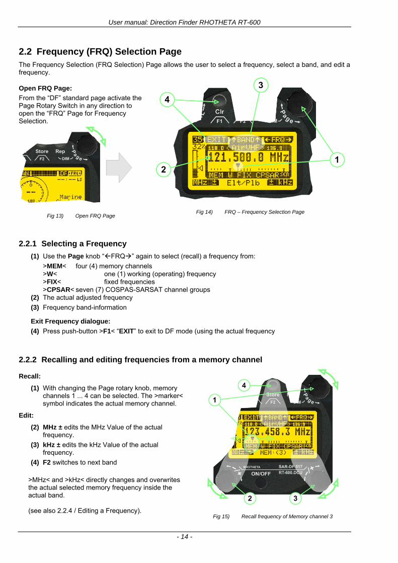
User manual Direction Finder RHOTHETA RT-600
- 14 -
22 Frequency (FRQ) Selection Page The Frequency Selection (FRQ Selection) Page allows the user to select a frequency select a band and edit a frequency
Open FRQ Page
From the ldquoDFrdquo standard page activate the Page Rotary Switch in any direction to open the ldquoFRQrdquo Page for Frequency Selection
Fig 13) Open FRQ Page
Fig 14) FRQ ndash Frequency Selection Page
221 Selecting a Frequency
(1) Use the Page knob ldquoFRQrdquo again to select (recall) a frequency from
gtMEMlt four (4) memory channels gtWlt one (1) working (operating) frequency gtFIXlt fixed frequencies gtCPSARlt seven (7) COSPAS-SARSAT channel groups
(2) The actual adjusted frequency
(3) Frequency band-information
Exit Frequency dialogue
(4) Press push-button gtF1lt ldquoEXITrdquo to exit to DF mode (using the actual frequency
222 Recalling and editing frequencies from a memory channel
Recall
(1) With changing the Page rotary knob memory channels 1 4 can be selected The gtmarkerlt symbol indicates the actual memory channel
Edit
(2) MHz plusmn edits the MHz Value of the actual frequency
(3) kHz plusmn edits the kHz Value of the actual frequency
(4) F2 switches to next band
gtMHzlt and gtkHzlt directly changes and overwrites the actual selected memory frequency inside the actual band (see also 224 Editing a Frequency)
Fig 15) Recall frequency of Memory channel 3
User manual Direction Finder RHOTHETA RT-600
- 15 -
223 Recalling frequencies from fixed frequencies or CospasSarsat Channels
Fig 16) FRQ Selection Page with FIX1 selected
(1) ldquoFIXrdquo Selection range for fixed frequencies
for RT-600 Standard version for RT-600 Law Enforcement version
FIX1 ldquoEltPlbrdquo 121500 MHz international VHF air distress emergency frequency
FIX2 ldquoChnl16rdquo 156800 MHz marine VHF emergency radio channel 16
FIX3 ldquoEltMILrdquo 243000 MHz military UHF air distress emergency frequency
FIX1 ldquoEltPlbrdquo 121500 MHz international VHF air distress emergency frequency
FIX2 ldquoChnl16rdquo 156800 MHz marine VHF emergency radio channel 16
FIX3 ldquoLE(USA)rdquo 173xxx MHz LoJack Recovery System
FIX4 ldquoETSSTDrdquo 216487 MHz ETS standard frequency
FIX5 ldquoETSUCVrdquo 216512 MHz ETS ucover frequency
(2) ldquoCPSARrdquo Selection range for Cospas Sarsat channel groups
CPSAR1 ldquo022-028rdquo 406022 hellip 028 MHz Channel A B C
CPSAR2 ldquo031-037rdquo 406031 hellip 037 MHz Channel D E F
CPSAR3 ldquo040-043rdquo 406040 hellip 043 MHz Channel G H
CPSAR4 ldquo046-052rdquo 406046 hellip 052 MHz Channel I J K
CPSAR5 ldquo055-061rdquo 406055 hellip 061 MHz Channel L M N
CPSAR6 ldquo064-070rdquo 406064 hellip 070 MHz Channel O P Q
CPSAR7 ldquo073-076rdquo 406073 hellip 076 MHz Channel R S
User manual Direction Finder RHOTHETA RT-600
- 16 -
224 Editing a Frequency
While on the FRQ SELECTION Page the user can directly edit the frequency displayed
Fig 17) FRQ Selection Page before frequency editing
(1) gtMHzlt Rotary switch for direct adjustment of the displayed MHz range inside the actual band
(1 x step = 1 MHz adjustment)
(2) gtkHzlt Rotary switch for changing the displayed kHz frequency according to the actual band frequency grid (as example 8333 kHz at the VHF airband)
(3) gtF2lt Adjustment of the next available band (see next page gtgt Selecting a Frequency Band)
Fig 18) FRQ Selection Page after frequency editing
If the selected and marked frequency is not one of the MEM [14] channels then the changed frequency is automatically stored in the work frequency WorkFRQ channel
User manual Direction Finder RHOTHETA RT-600
- 17 -
225 Selecting a Frequency Band
While on the FRQ Selection Page each available band can be selected by pressing F2 BAND
(1) Press push button F2 BAND for
switch over to the next band
(2) Designation of actual selected band
(3) Max frequency limits of the actual selected band (depends on wide band options)
Fig 19) FRQ Selection Page (bands)
Frequency bands availability depends on the system version (A LE) and its wide band options (F1 to F4) These optional wide bands are available if ordered in addition to the default bands Here is a listing of DEFAULT and OPTIONAL bands available with each version of the system RT-600 (STANDARD) Listing of bands
Default bands available OPTIONAL extended bands available
Band designation Frequency limits Option Designation Frequency limits
VHF Emergency Band 118000 hellip 124000 MHz gt F1 VHF Air Band 118000 hellip 136992 MHz
VHF Marine Band 154000 hellip 163000 MHz gt F2 Extended VHF Marine 137000 hellip 224995 MHz
UHF Emergency Band 240000 hellip 246000 MHz gt F3 UHF Air Band 225000 hellip 399975 MHz
COSPAS SARSAT 400000 hellip 406092 MHz
UHF FM Band 406100 hellip 410000 MHz gt F4 Additional UHF FM 406100 hellip 470000 MHz
RT-600 (Law Enforcement) Listing of bands
Default bands available OPTIONAL extended bands available
Band designation Frequency limits Option Designation Frequency limits
VHF Emergency Band 118000 hellip 124000 MHz gt F1 VHF Air Band 118000 hellip 136992 MHz
VHF Marine Band 154000 hellip 163000 MHz gt F2 Extended VHF Marine 137000 hellip 163000 MHz
LoJack 164000 hellip 174000 MHz
ETS 216000 hellip 220000 MHz
COSPAS SARSAT 400000 hellip 406092 MHz
User manual Direction Finder RHOTHETA RT-600
- 18 -
23 Direction Finder (DF) Mode Direction Finder (DF) mode is generally used to display all valid information processed by the DF from the signal received from a target transmitter The amount and kind of information displayed by the DCU depends on the type and content of the signal received and processed by the DF Simple signals such as the analog sweep-tone modulation received from a SAR beacon (ELT PLB EPIRB PDD) on 121500 MHz allow displaying only basic bearing information while digital signals such as COSPAS-SARSAT and LOJACK allow displaying more information for ex beacon IDs GPS coordinates codes VLUs etc
231 Operating Elements in DF Mode
Fig 20) Operational Elements in DF Mode
This picture shows the DCU operating in DF Mode on the international emergency frequency 121500 MHz
with an active signal being received (1) gtFREQUENCYlt Rotary switch activates the ldquoFRQrdquo frequency page for changing and selecting the
active frequency The last selected frequency remains stored after switching offon the device The selected frequency is shown on the graphic display bottom right Above additional information for the selected frequency is displayed The use of the rotary switch activates a sub-page Please refer to the Frequency Selection section for details
(2) gtVOLUMElt Rotary switch to adjust the audio output level The volume of a linked external speaker or amplifier can be adjusted in a range from 0 (off) to 99 (maximum loudness) The selected volume is shown in the bottom left corner of the graphic display The volume remains stored after switching offon the device
(3) gtSquelch Levellt adjusts the squelch level The squelch level has to be above the receiving level without signal (noise) Only signals above the squelch level are audible in the loudspeaker and used by the direction finder for bearing indication The gtSQLlt rotary switch allows to select the squelch threshold ie a minimum signal strength of an incoming signal to be processed The current settings on a signal level scale from 0 to 60 is shown in bright letters on dark background below the SQL rotary switch and as an arrow beside the signal Strength Bar-Graph
(4) The gtCLRlt Push-button is used for erasing the internal bearing value averaging store and the Last Signal Timer To activate this function the push-button has to be hold down for a minimum of circa two seconds The sophisticated averaging store increases bearing precision and enables at all an usable
User manual Direction Finder RHOTHETA RT-600
- 19 -
bearing display in case of bad receiving signals (if there is a far away transmitter andor temporary complete loss of a receiving signal) Caused by the averaging procedure a drag error may occur which might be disturbing the bearing indication after a quick change of course of the aircraft or vehicle In this case the indicated bearing value lags by the real bearing value for about two seconds (for very weak signals even longer) By pressing this push-button after a quick change of course the display will show the new bearing value without drag error Additionally the F1CLR Push-Button is used to activate specific functions high-lighted in the menu below the button by pushing it for a short time (here as example ldquoSCANrdquo starts scanning the actual air band)
(5) gtSTORElt push-button Without function except if a special function is high-lighted in the menu line of the display
(6) gtREPEATlt Push-button when pressed and hold for min 3 sec the last valid bearing value with corresponding receiving level is displayed
232 Standard Display in DF Mode
Fig 21) DF Mode
(1) gtRelative Bearing valuelt by means of a sophisticated averaging procedure a steady display is
accomplished as graphic display and as text in the range of 0deghellip 359deg (0deg corresponds to bearing direct ahead)
(2) gtSpreadlt maximum deviation of un-averaged bearing values This is an indicator of bearing quality The wider the range between the directions of maximum deviation the worse the received signal is As a result of the excellent averaging procedure even with a spread of 45deg good bearing results are achieved
(3) gtReceiving levellt (field strength) of the signal as a relative percentage value visualized as bar-graph indication and as decimal value Even without a received signal a certain noise level may be displayed
(4) gtSquelch levellt (independently adjustable and stored for each frequency band) Squelch level is indicated as marker at the Signal Strength Bar-Graph or as direct relative level value A usable bearing analysis can only be achieved if the squelch level is above the noise level (without received signal) If the antenna unit is placed close a heavily disturbing electronic devices the squelch level has to be raised thus making the direction finder being less sensitive In receive modes where the squelch level is set automatically an ldquoArdquo above the marker indicates the ldquoAutosquelchrdquo functionality
(5) gtLast Signallt timer showing the time since a signal has been received for the last time (ie since a signal has been stronger than the squelch level) Values are ldquominutes secondsrdquo
User manual Direction Finder RHOTHETA RT-600
- 20 -
233 Special Options in COSPAS-SARSAT DF Mode
Especially for the use together with beacons transmitting a data signal according to COSPAS-SARSAT specifications in the 406-MHz-Band special functionalities and pages are being provided After selection of a COSPASSARSAT Frequency (Refer to the chapter ldquoFrequency selection Pagerdquo) the bearing page provides additional information and operating options
Fig 22) Operational Elements and Display in COSPAS-SARSAT DF Mode
(1) gtAuto Squelchlt indication indicating that the squelch level is set automatically to be close to the noise
floor It is recommended to always use the Auto Squelch during COSPAS-SARSAT operation This can be achieved by manually selecting 0 (lowest possible value) or 60 (highest possible value) as squelch level During COSPAS-SARSAT-Operation this will force the automatic setting of the level
(2) gt121500lt menu option The COSPAS-SARSAT signal in the 406 MHz band is transmitted only every 50 seconds in form of a short data burst of 440 or 520 ms approaching the transmitter it will be received earlier than the 121500 MHz continuous signal due to its high transmitter power However in a lower distance to a transmitter bearing on 121500 MHz is faster thanks to the continuous or rapidly intermittent signal The 121500 MHz menu option allows a direct switch-over to 121500 MHz Direct return back from 121500 to the COSPAS-SARSAT band is possible from the 121500 MHz bearing Window in COSPAS-SARSAT mode Please refer to the chapter ldquo121500 MHz bearing Window in COSPAS-SARSAT moderdquo for details
(3) gtDecodelt menu option allows to open the COSPASSARSAT Decode sub-page by shortly pushing the F2 push-button above the menu option
(4) gtFrequency rangelt indication COSPAS-SARSAT is using a channel spacing of 3 kHz for its beacons Due to the internal architecture of the direction finder it is possible to receive more than one channel in the same time Thus frequency steps of the direction finder are 833 kHz instead of 3 kHz The receive frequency covered by the current receive frequency setting is shown in the display line above the receive frequency indication
Important If the exact frequency of the COSPAS-SARSAT beacon is unknown it is strongly recommended to use the COSPAS-SARSAT scanning functionality in order to detect the correct frequency (Refer to the chapter ldquoFrequency selection Pagerdquo amp ldquoCOSPAS-SARSAT Scan Moderdquo)
User manual Direction Finder RHOTHETA RT-600
- 21 -
234 COSPAS-SARSAT Decode Window
The COSPAS-SARSAT Decode Window allows decoding incoming COSPAS-SARSAT data messages Only while this decode window is activated the decoding is possible An already received COSPAS-SARSAT puls while DF bearing mode was activated can not be used for decoding afterwards In this case the user has to wait while this decode window is active for the next transmitted puls approx 50 sec later
Fig 23) COSPAS-SARSAT Beacon Information Page
(1) gtExitlt push button (F1 button) allows to exit the decode window and switch back to the COSPAS-
SARSAT DF Mode page
(2) gtSARSATlt in the upper right corner of the display indicates that the COSPAS-SARSAT decode function is activated
(3) gtCountrylt displays the COSPAS-SARSAT Country Code coded into the received data message
(4) gtLast Signallt time since the last COSPAS-SARSAT message has been received in minutes secondsrsquo format
(5) gtPositionlt field showing in case of location protocols being used by the beacon the encoded GNSS position data (latitude longitude) transmitted by the beacon
(6) gt15-HEX-IDlt 15-HEX-ID of the beacon in hexadecimal format
(7) gtData stringlt of the bits 25 to 112 of the COSPAS-SARSAT data burst in case of short messages and bits 25 to 144 in case of a long message format The last 8 Hex Values are separated by a blank Bit- and Frame-synchronization hex values (Bits 1 to 24) are suppressed to increase the readability of the data message
(8) gtXlt sign to indicate that the Squelch is controlled by the antenna unit for optimum sensitivity The user has no access to the Squelch setting
User manual Direction Finder RHOTHETA RT-600
- 22 -
235 Tracking 121500 MHz while in COSPAS-SARSAT Mode
While in COSPAS-SARSAT DF Mode the user can switch to 121500 MHz in order to track the beacon in VHF If a valid signal is not received in 121500 MHz the user can switch back to the last active COSPAS-SARSAT channel (406 MHz frequency) being tracking previously
Fig 24) Tracking 121500 MHz while in COSPAS-SARSAT Mode
Differences are (1) gt406xlt press F1 to switch back to the last
COSPAS-SARSAT channel (406 MHz frequency) being tracking previously
(2) gt121500 MHzlt Actual frequency being tracked
User manual Direction Finder RHOTHETA RT-600
- 23 -
236 COSPAS-SARSAT Scan Mode
If the COSPAS-SARSAT Scan Mode has been selected at the frequency selection page ldquoFRQrdquo the COSPAS-SARSAT channels as selectable manually from the Frequency Selection Page are scanned After reception of a COSPAS-SARSAT Signal the scanning is stopped at the received frequency Due to the fast scanning ndash the complete COSPAS-SARSAT sub-band is scanned within less than 400 ms ndash detection of a receivable COSPAS-SARSAT signal is possible within one COSPAS-SARSAT repetition cycle
Fig 25) FRQ Selection Page with SCN COSPAS-SARSAT Scan Page selected
At the frequency selection page an active COSPAS SARSAT scanning can be stopped by de-activating it with the rotary button (1) While the scanning is active it is also possible by pressing gtF1lt ldquoEXITrdquo to switch back to the DF pagehellip
Fig 26) DF page with active COSPAS-SARSAT Scan Mode at the DF page
(1) gtSCANlt flashing indication notifying the user that the equipment is operating in scan mode
(2) Frequency display indicating the COSPAS-SARSAT scanning frequency range
(3) gtXlt sign showing that squelch settings are controlled autonomously by the receiver
Scan mode can be left by pressing gtF1lt ldquoSTOPrdquo
User manual Direction Finder RHOTHETA RT-600
- 24 -
237 Marine Ship Scan Mode
Fig 27) DF Mode FRQ = 156800 MHz F1 for scan function
If the active frequency (2) is within the VHF Marine Band a fast scan of all ship channels is possible by pushing gtF1lt ldquoSCAN (1) In this scanning mode all marine channels 1 to 88 (156025 to 157450 MHz) are scanned continuously until a signal is received To offer the best monitoring functionality for the user also signals between to channels (4) are detected (scanning without gap) In order to prevent the scan to stop on noisy frequencies it is recommended to start scanning with high squelch settings You can reduce the squelch level in steps until the scan stops on a noisy frequency for the first time Then increase the squelch level slightly This will result in the highest possible scan sensitivity and avoiding noisy channels due to RF disturbances sometimes generated by other equipment in own aircraft
Fig 28) DF Mode active scanning in process
The scanning is stopped by pressing gtF1lt ldquoSTOPrdquo (3)
User manual Direction Finder RHOTHETA RT-600
- 25 -
24 Law Enforcement Operation Law enforcement special ops and other organizations use the RT-600 LE (LAW ENFORCEMENT) version instead of the RT-600 A (STANDARD) version One of the reasons is that the LE version features scanning and tracking of signals like LoJack and ETS as well as signals in the 216000 MHz ndash 220000 MHz band such as medical beacons wristankle transmitters cashasset recovery ldquotagsrdquo etc However the LE version shares many functions in common with the A version such as scanning and tracking in the AIR band COSPAS-SARSAT band etc
241 Power-On procedure
The power-on procedure is the same as described in 211
(1) System Version ldquo(L)rdquo for LAW ENFORCEMENT version
Fig 29) STARTUP Screen (see 211 for details)
242 LoJack Scan Mode Start scanning for a VLU Code
For the convenience of Law Enforcement and other special ops users who frequently engage in tracking SVRS (Stolen Vehicle Recovery System) signals such as LoJack (LoJack Corp FCC 9020 Part 2 SVRS) RHOTHETA has optimized the power-on procedure of the RT-600 LE version so that right after the STARTUP screen the unit displays automatically the LoJack Scan Mode page to start immediately scanning for a valid VLU (Vehicle Location Unit) code without pressing any key
Fig 30) LoJack Scan Mode unit is scanning for a LoJack VLU Code
(1) gtscan LoJacklt DF is scanning for any new LoJack VLU Code
(2) gtEXITlt press F1 to exit and switch directly to DF Mode
User manual Direction Finder RHOTHETA RT-600
- 26 -
243 LoJack Scan Mode from any other page
While operating on any page other than the LoJack Scan page the user can switch directly to LoJack Scan Mode by pressing Hotkey F2 for 2 secs
(1) press Hotkey F2 for 2 secs to switch to the LoJack Scan page
Fig 31) Hotkey F2
User manual Direction Finder RHOTHETA RT-600
- 27 -
244 Manual activation of LoJack Scan Mode
(1) select the LoJack frequency (see also Frequency Selection Page)
(2) press F1 to switch back to the DF MODE
Fig 32) FRQ Selection Page FRQ = LoJack BAND = LoJack (164-174 MHz)
While in DF MODE with adjusted LoJack frequency the user can switch directly to the LoJack Scan by pressing gtF1lt ldquoSCANrdquo
(1) press F1 SCAN to switch to the LoJack Scan page
(2) still no LoJack ID filter used (ID=off) all transmissions are received on the active frequency as example also unwanted tower pulses
Fig 33) DF Mode with LoJack filter OFF
User manual Direction Finder RHOTHETA RT-600
- 28 -
245 Receiving and accepting a new VLU Code
While in LoJack Scan Mode waiting for a VLU Code if a new VLU Code is displayed the user can accept it and switch directly to DF Mode by pressing F2
(1) a new LoJack VLU Code (0001A) has been received
(2) press F2 to accept the new VLU Code (0001A) and switch to DF MODE page with the LoJack filter activated to track only 0001A
Fig 34) LoJack Scan Mode with new VLU Code received
246 Entering a new VLU Code manually
While in LoJack Scan Mode the user can enter a LoJack VLU code also manually
(1 2 3) use the SELECTplusmn and plusmnVALUE knobs to enter a new LoJack VLU Code active ID (0001A)
(4) Press F1 to accept the new VLU Code and switch to DF Mode with the LoJack filter ON to track only 0001A
Fig 35) LoJack Scan Mode with new VLU Code entered manually
User manual Direction Finder RHOTHETA RT-600
- 29 -
247 Tracking one VLU Code while monitoring new VLU Codes
While on DF Mode and tracking a VLU Code (0001A) the user can turn the LoJack switch OFF with F2 also the user can start scanning all VLUs again with F1
0001A is displayed as the active VLU Code filter function is ON only 0001A is tracked
Monitoring of other VLU Codes is active in the background
(1) Press F1 to switch to the LoJack Scan Mode to scan for new VLU Codes
(2) Press F2 to switch LoJack filter OFF
Fig 36) DF Mode with active VLU Code and LoJack filter ON
248 Tracking one VLU Code and receiving a new VLU Code
While on DF MODE page and tracking VLU Code (0001A) in the background a new VLU Code is received and decoded (G2HC7)
(1) The new VLU Code is announced (NEW G2HC7)
(2) Press F1 to switch to LoJack Scan Mode to see the arrival time of G2HC7 and the possibility to change bearing to this new G2HC7
Fig 37) DF Mode with active VLU Code and announcement of new VLU Code
User manual Direction Finder RHOTHETA RT-600
- 30 -
249 Switching to a new VLU Code
While on the LoJack Scan Page tracking one VLU Code (0001A) and notified of a new VLU Code (G2HC7)
(1) press F1 to continue tracking 0001A
(2) press F2 to start tracking G2HC7
(3) Time elapsed since G2HC7 was last received
(4) Time elapsed since 0001A was last received
If F1 is pressed for 2 sec the indicated VLU Code (G2HC7) and ID (0001A) are deleted
Fig 38) LoJack Scan Page with one active VLU Code and one new VLU Code
2410 ldquoBlockingrdquo function of one LoJack VLU Code
The LoJack scan page can also be used to ldquoblockrdquo one unwanted LoJack VLU ID signal by separating the adjusted active ID from any other received LoJack VLU signal This is done by muting the audio (see example below) when a LoJack signal with VLU code ldquo0001Ardquo is received gtgt Any new VLU Code (active LoJack signal) - except for 0001A ndash will be displayed on the top row and generate the audible beep tone
Fig 39) LoJack Scan Page with one active VLU Code and audio OFF
Tip ldquoBlockingrdquo is an important tool for practical missions As example a stolen vehicle with VLU ID ldquo0001Ardquo was tracked in the DF bearing mode The mission
is completed but the VLU is normally still transmitting With the settings above only new VLU signals except the now unwanted ldquo0001Ardquo are audible and displayed in the upper (scan LoJack hellip for new VLU) box
User manual Direction Finder RHOTHETA RT-600
- 31 -
2411 Tracking in the 216 to 220 MHz band
The RT-600 features scanning and bearing functionality in the 216000 MHz to 220000 MHz band The 216000 MHz ndash 220000 MHz band contains frequencies and signals used by special services and tracked by law enforcement special ops and similar organizations These are some of the frequencies and services in this band
CFR 90259 tx 216000 MHz to 220000 MHz
Low Power Radio Service (LPRS) tx 216000 MHz to 217000 MHz
Medical beacons Project Lifesaver tx wristankle tx 213000 MHz to 216000 MHz
ETS tx stolen cashasset recovery tx ldquobaitrdquordquotagrdquo tx 216000 MHz to 220000 MHz tx = transmitter(s) However any future or current user of the Rhotheta RT-600 must be aware that tracking signals on the frequencies listed above may be challenging and even frustrating due mostly to negative factors in some of the transmitters
bull Very low RF power output
bull Inefficient antennas
bull Battery-powered devices with a ldquolow batteryrdquo condition
bull Devices worn or located in conditions of poor RF propagation
bull Devices with channel spacing different than the one specified for the RT-600
These factors can make it very difficult for the DF to receive the signal andor display an accurate bearing Disclaimer For the reasons explained above and even though the RT-600 features top performance in its class RHOTHETA does not offer - and is not to be held responsible for - any guaranteed minimum range or distance to a transmitter in this band
25 Setup Edit Page System settings are displayed in the setup page The functions described in this section should be used by trained personal only
Fig 40) Accessing the Setup Page
The setup page can be accessed by holding down the gtCLRlt (1) and gtREPlt (2) buttons simultaneously and in the same time performing a left-hand turn on the gtPagelt rotary switch (3)
User manual Direction Finder RHOTHETA RT-600
- 32 -
Fig 41) Setup Page
(1) gtStorelt push-button must be pressed in parallel if a value of a setting shall be modified If a value can
be modified the background stops to blink
(2) gtSelectlt rotary switch used to scroll through the menu options The value of the actually activated menu option is high-lighted with dark background and blinking
(3) gtValuelt rotary switch used to change values in menu options (gtStorelt (1) has to be pressed in parallel if a value shall be modified)
(4) gtSN-Ratiolt menu option representing the necessary Signal-To-Noise-Ratio (Difference between signal and noise level) used as criterion for the automatic squelch function Please refer to the chapter ldquoSquelch Operationrdquo for details Default value is 60 dB
(5) gtMounting Positionlt menu option to select Top- or Bottom-Mounting of the DF antenna In case of rooftop installation (eg on land vehicles) ldquoToprdquo shall be selected In case of bottom-down (upside-down) installation (eg on a helicopter) ldquoBotrdquo shall be selected If this option is not selected correctly all bearing values will be mirror-inverted
(6) gtBearing Offsetlt menu option to include a constant offset correction to the bearing indication Bearing values in degrees will be changed according to the offset value
(7) gtMaximum External Dimming Voltage for Legendslt menu option which sets the upper limit of the dimming input voltage for the legends-panel Range=[15 hellip 28]V
(8) gtMinimum External Dimming Voltage for Legendslt menu option which sets the lower limit of the dimming input voltage for the legends-panel Range=[15 hellip 28]V
(9) gtPagelt rotary switch to be turned right-hand to go back to the Direction Finder page A left-hand turn on this rotary switch will show up an additional service page with debug information used for system checks
(10) gtExtended Seriallt It is possible to enable or disable the extended serial data protocol Only of interest if serial data is used by any connected control units like moving maps or computers For detailed information see (Serial interface data protocol (short description)gt at page 46) If there are compatibility problems with already existing older remote control software it is recommended to switch OFF the extended serial data protocol
User manual Direction Finder RHOTHETA RT-600
- 33 -
3 Error messages If an internal error of the device is recognized a corresponding flashing error message will be shown in the DF pages
Fig 42) Error Messages
(1) Error message including error code (in brackets)
(2) Short description of the indicated error
In case of coincidence of various errors the error with the highest priority will be displayed
Error message Error location Reason
Error (12) VOLTDU
Main voltage supply Main Voltage input too low ( 100 V)
Error (11) NO AU
Connection antenna display or Antenna Unit
No serial data (RS485) from Antenna Unit No or damaged connection between antenna and display or damaged antenna unit
Error (10) BAD AU
Connection antenna display
Incompatibility or bad data connection between display and antenna
Error (9) BAD RU
Remote Unit Incompatibility or bad data connection between display and external serial Remote Unit or PC
Error (8) VOLTAU
Antenna Unit Voltage supply at Antenna Unit too low ( 90 V) Main voltage supply too low or considerable drop of voltage between display and antenna
Error (7) BAD DCU
Connection Display Antenna
Incompatibility or bad data connection between antenna and display
Error (6) NO DCU
Connection Display Antenna
No serial data from Display Control Unit to Antenna Unit
Error (5) PLL ERR
antenna Error in synthesizer-oscillator of receiver in Antenna Unit
Error (4) FRQ+OFS
received transmitter Received frequency too high (more than 6 KHz error of transmitter)
Error (3) FRQ-OFS
received transmitter received frequency too low (more than 6 KHZ error of transmitter)
Error (2) DECODE
radio distance transmitter DF
Data Bits of decoded signal (COSPAS-SARSAT or LoJack) defective
Error (1) DATARNG
Incompatibility of data DCU AU
Protocol data bytes out of valid range
Error (0) NO REC
Antenna Unit receiver
Receiver board defective
User manual Direction Finder RHOTHETA RT-600
- 34 -
4 Installation
41 Antenna unit A convenient position of the monopole bearing antenna is crucial for good bearing results The antenna needs an effective ground connection to the body of the aircraft or to the roof of the vehicle If there is no metallic mounting surface available a metallic sheet or similar (net) with connection to ground has to be applied first between vehicle-body and antenna In this hatched area the antenna touches the body ofthe vehicleaircraft In order to obtain a good groundconnection the surface of the body should be bared(Measuring unit [mm])
8 x holes for mounting the antenna unit to the
vehicle aircraft
Fig 43) Antenna Mounting Drawing
User manual Direction Finder RHOTHETA RT-600
- 35 -
411 Influence of antenna location and environment on the bearing accuracy
Recommendations concerning the practical antenna unit location on helicopters and airplanes
The bearing accuracy of the direction finder antenna unit is severely influenced (comparable to an airspeed sensor) by the environment For comparison a perfect high quality speed sensor will not indicate the true airspeed if this sensor is interfered by strong turbulences The direction finder antenna unit acts as a sensor for electromagnetic waves In the near field of this antenna unit any conductive (eg metallic) obstacle will influence the incoming wave field and create reflections which decrease the bearing accuracy These are general physical limitations concerning all types of direction finder systems To achieve the best bearing results it should be considered that the antenna unit is installed as far away as possible from any other vertically polarized conductive structure If possible there should be no reflectors within an area of 2-3 feet around the antenna unit In this worst case example the direction finder will not work properly
Fig 44) Antenna Installed in a Bad Location
In this example the antenna unit is located too close to the cable cutter of the helicopter This cutter will produce strong reflections especially as the length is equal to Lambda4 within the VHF airband
User manual Direction Finder RHOTHETA RT-600
- 36 -
Examples of properly installed direction finder antenna units
Fig 45) Antenna Installed in Good Locations
User manual Direction Finder RHOTHETA RT-600
- 37 -
42 Display and Control Unit
The display control unit may be mounted into a front panel by the means of this mounting drawing
Fig 46) DCU Mounting Drawing
(all dimensions in [mm]) To install or uninstall the display control unit perform the following steps (1) Remove the cover caps of the four rotary switches
(2) Loose the screws visible below the position of the cover caps
(3) Remove the plastic button from the axis of the four rotary switches
(4) Mount dismount the display control unit
(5) Re-install the plastic buttons on the axis of the four rotary switches
(6) Fix the screws so that the plastic buttons are fixed on the axis
(7) Re-install the cover caps on the four rotary switches
User manual Direction Finder RHOTHETA RT-600
- 38 -
43 System Interconnect Wiring Diagram (Also refer to chapter ldquoTechnical Datardquo for details)
Fig 47) System Interconnect Wiring Diagram
6-pol Amphenol plug femalePTG06SE10-6S(SQ)
max length of cable 20 m 9-pol Sub-D plug (femalemale)
User manual Direction Finder RHOTHETA RT-600
- 39 -
5 Technical Data
51 Electric features
Method of bearing Doppler-principle (3 kHz rotational frequency right left rotation)
Bearing accuracy1 plusmn 5deg RMS
Internal resolution 1deg
Bearing Sensitivity VHF AirEmergency le 25 μVm (typical)
VHF Marine le 25 μVm (typical)
UHF Emergency and ETS le 4 μVm (typical)
COSPAS-SARSAT le 4 μVm (typical)
LoJack Decoding (50 Message Error Rate) and bearing le 5 μVm (typical)
Frequency stability plusmn 20 ppm (Δff = plusmn210-6)
Reception frequencies
SAR version (Standard)
Frequency Options
VHF Emergency Band 118000 to 124000 MHz (833 kHz steps AM)
VHF Marine Band 154000 to 163000 MHz ( 500 kHz steps FM) (channel 16 selectable via channel no)
UHF Emergency Band 240000 to 246000 MHz (2500 kHz steps AM)
UHF FM Band 406100 to 410000 MHz ( 500 kHz steps FM)
COSPAS-SARSAT 400000 to 406092 MHz Including 406022 to 406076 MHz (Channel A S)
F1 VHF Air Band 118000 to 136992 MHz
F2 extended VHF Marine Band 137000 to 224995 MHz
F3 extended UHF Air Band 225000 to 399975 MHz
F4 additional UHF FM Band 406100 to 470000 MHz
Reception frequencies
LAW Enforcement version
Frequency Options
VHF Emergency Band 118000 to 124000 MHz (833 kHz steps AM)
VHF Marine Band 154000 to 163000 MHz (500 kHz steps FM) (channel 16 selectable via channel no)
LoJack 164000 to 174000 MHz (125 kHz steps FM)
ETS 216000 to 220000 MHz (10125 kHz AM)
COSPAS-SARSAT 400000 to 406092 MHz Including 406022 to 406076 MHz (Channel A S)
F1VHF Air Band 118000 to 136992 MHz
F2 extended VHF Marine Band 137000 to 163000 MHz
COSPAS-SARSAT fast scan mode
Full automatic detection of any active COSPAS-SARSAT channel A to S within 400 ms
COSPAS-SARSAT decoding
Reception and decoding of COSPAS-SARSAT data signal (112 or 144 bit) specified according to COSPAS-SARSAT
LoJack decoding Selectable LoJack ID display and selective active filtering
Special scanning modes
complete maritime ship band scanning within 3 s (channel 01 hellip 88 also frequencies between 2 channels are included)
1With undisturbed wave field and sufficient field strength Measuring by changing the angle of incidence with the antenna rotating on a revolving table in order to eliminate environmental influences on the results No modulation
User manual Direction Finder RHOTHETA RT-600
- 40 -
Bearable modulation A3E F3E A3X (ELT-modulation) F1D G2D COSPAS-SARSAT Bearing largely independent of modulation
Polarization Vertical
Polarization error 5deg at 60deg field vector rotation
Garbling cone Ca 30deg to the vertical
Time of response2 50 ms (with sufficient reception field strength)
LC-graphic display 128 x 64 pixels supertwist transflective extended range of temperature dark-blue display on yellow-green background background light Freely adjustable (exponential) dimming of brightness
NVG cockpit design Fully compatible NVIS Green B display Control Unit optional
Operating voltage 275 V nominal 12 V to 35 V DC
Current consumption LCD-background light Off max 500 mA (12 V DC) max 250 mA (24 V DC)
LCD-background light 100 max 750 mA (12 V DC) max 350 mA (24 V DC)
LCD-background light 100 max 900 mA (12 V DC) with NVG Option max 400 mA (24 V DC)
Audio out For external speaker approx 2 W (4 Ω)
Serial data interface Serial interface RS-232 (9600 baud 8 data bits 1 stop bit no parity)
2Very weak signals can considerably increase the time of response
User manual Direction Finder RHOTHETA RT-600
- 41 -
52 Interface External connections (optional at Sub-D 9-pol Male connector)
Dimming
Pin 8
external voltage input for variable dimming of legends
(optional)
Analog input signal for variable control of the legends illumination Input voltage range is freely adjustable in the range of 15 hellip 28 V in the setup menu Refer to chapter ldquoSetup Pagerdquo Default setting 8 hellip28 V (8 V = Off 28 V = max dimming for legends)
Input Impedance gt 50 k
Pin 6 night status line for LCD
dimming (optional)
Low-active (as example switch to ground) At input voltage lt 25 VDC the LCD dimming operates in nightNVG mode Maximum brightness ca 4 of daydefault mode brightness
Input Impedance gt 50 k
Pin 4 NVG status line for LCD
dimming (optional)
Low-active (as example switch to ground) At input voltage lt 25 VDC the LCD dimming operates in nightNVG mode Maximum brightness ca 4 of daydefault mode brightness
Input Impedance gt 50 k
AudioLF
Pin 7 Audio output signal
AC coupled voltage source with very low inner resistance Maximum output voltage ca 8 VPP = 283V RMS at maximum Volume Maximum output power ca 2 W with 4 speaker
If a headphone is connected ([32hellip600] 100mW) we recommend using a resistor (18 025 W) between audio output and headphone to prevent damage of the headphone
Serial interface RS232 (9600 baud 8 data bits 1 stop bit no parity)
Pin 3 TXD Serial output (ca plusmn10 V)
Pin 2 RXD Serial input (ca plusmn10 V)
User manual Direction Finder RHOTHETA RT-600
- 42 -
53 Mechanical features
Temperature range
Display Control Unit permissible operating temperature3 -20 degC +60 degC permissible storage temperature -30 degC +80 degC
Antenna Unit permissible operating temperature3 -40 degC +60 degC permissible storage temperature -55 degC +80 degC
Protective system Antenna Unit IP 67
Weights Display Control Unit 250 g Antenna Unit 2000 g
Dimensions Display Control Unit 82 mm x 82 mm x 43 mm (width x height x depth) Antenna Unit 270 mm x 185 mm
Fig 48) DCU Mechanical Drawing (all dimensions in [mm])
3 For temperatures lower than ndash10deg C a warm-up period of 15 min should be allowed
User manual Direction Finder RHOTHETA RT-600
- 43 -
Fig 49) AU Mechanical Drawing (all dimensions in [mm])
User manual Direction Finder RHOTHETA RT-600
- 44 -
6 Appendix
61 Frequency Ranges
User manual Direction Finder RHOTHETA RT-600
- 45 -
62 Frequencies of channels on maritime band (only for standard [A] version) Frequency-range of the RT-600 in the maritime band 156000 MHz 162025 MHz
Channel No frequency (ship - station) Frequency (coast - station)
1 156050 MHz 160650 MHz 2 156100 MHz 160700 MHz 3 156150 MHz 160750 MHz 4 156200 MHz 160800 MHz 5 156250 MHz 160850 MHz 6 156300 MHz 160900 MHz 7 156350 MHz 160950 MHz 8 156400 MHz 9 156450 MHz
10 156500 MHz 11 156550 MHz 12 156600 MHz 13 156650 MHz 14 156700 MHz 15 156750 MHz 16 156800 MHz 17 156850 MHz 18 156900 MHz 161500 MHz 19 156950 MHz 161550 MHz 20 157000 MHz 161600 MHz 21 157050 MHz 161650 MHz 22 157100 MHz 161700 MHz 23 157150 MHz 161750 MHz 24 157200 MHz 161800 MHz 25 157250 MHz 161850 MHz 26 157300 MHz 161900 MHz 27 157350 MHz 161950 MHz 28 157400 MHz 162000 MHz 60 156025 MHz 160625 MHz 61 156075 MHz 160675 MHz 62 156125 MHz 160725 MHz 63 156175 MHz 160775 MHz 64 156225 MHz 160825 MHz 65 156275 MHz 160875 MHz 66 156325 MHz 160925 MHz 67 156375 MHz 68 156425 MHz 69 156475 MHz 70 156525 MHz 71 156575 MHz 72 156625 MHz 73 156675 MHz 74 156725 MHz 75 156775 MHz 76 156825 MHz 77 156875 MHz 78 156925 MHz 161525 MHz 79 156975 MHz 161575 MHz 80 157025 MHz 161625 MHz 81 157075 MHz 161675 MHz 82 157125 MHz 161725 MHz 83 157175 MHz 161775 MHz 84 157225 MHz 161825 MHz 85 157275 MHz 161875 MHz 86 157325 MHz 161925 MHz 87 157375 MHz 161975 MHz 88 157425 MHz 162025 MHz
User manual Direction Finder RHOTHETA RT-600
- 46 -
63 Serial interface data protocol (short description)
631 General
Interface parameters RS232 9600 Baud 8 databits 1 stopbit no parity LSB sent first Timing of serial data For accurate use of the serial data (even for the optional serial input commands) the correct timing is mandatory The DCU (Display Control Unit) sends out via the RS-232 Pins (see 43 System Interconnect Wiring Diagram page 38) cyclic and autonomous every approx 250300 ms a binary data stream which contains all relevant DF-bearing information The output data contains one or two blocks of binary data (see next picture with accordingly description) The optional serial input is only used if changes (as example frequency change) are done by additional remote control units
Fig 50) Timing of serial data
Serial standard output
This output data is always available and contains all relevant DF-bearing data For detailed content see page 47
Optional extended serial output
This data contains some additional information like as example CospasSarsat or LoJack decoding and ID data For detailed content see page 50 The data is only available with DCU Software [Rev ge 320] and if this optional data block is configured as ON = enabled (see Setup Edit Page point (10) )
Even to avoid compatibility problems with already existing older remote control software it is possible to disable switch off this additional data block (see Setup Edit Page point (10) )
Optional serial input
Only used for optional commands to control DCU parameters If as example the direction finder frequency is changed remotely there is send to the DCU one time this data block with the new frequency For detailed content see page 52
User manual Direction Finder RHOTHETA RT-600
- 47 -
632 Serial standard output (protocol description)
Specification serial standard output
The binary data stream with a length of 39 bytes starts with a header byte (value = hex 0xA0 as ID for DF Mode) The next bytes contain different values for status bearing information and also service The last byte is used for data stream checksum control Remark This is a binary data protocol So every byte value from 0dec hellip 255dec (0x00 hellip 0xFF) is possible Because of this it is not allowed to realize a start byte detection by the content (0xA0) The idle line detection is recommended for detection the end of message Register of databytes (for details see next page)
byte no
[0] Header = 0xA0 Id for DF Mode
[1] Number = 39 = bytes in the complete message (including header and checksumbyte)
[2] Status (1) HSB [x|x|x|x|x|x|x|x] LSB | | | | | | | --gt (0) Receiving | | | | | | ----gt (1) Squelch controlled by AU (X) | | | | | ------gt (2) Permission RL Calibration | | | | --------gt (3) Line Night | | | ----------gt (4) Line NVG | | ------------gt (5) Dimming External | --------------gt (6) Autosquelch Active ----------------gt (7) 0=Standard Version 1=LE Version
[3] Status (2) HSB [x|x|x|x|x|x|x|x] LSB | ----------------gt (7) 0=Standard 1=extended serial dataprotocol = ONactive
[45] Error (Bits[120])
[6] Actual DCU Page
[7] Volume [0hellip100]
[811] Frequency [Hz]
[12] Active Band
[13] Actual Squelchlevel [0hellip60]
[14] Audio-Line amp_NF_Test Output
[15] (Not used)
[1617] Voltage_DCU ([0hellip335]=[0 hellip 335]V
[1819] Voltage_AU ([0hellip255]=[0 hellip 255]V
[20] Temperature_AU [-68hellip+127]degC
[21] Frequency Offset [-99hellip+99]
[2225] ServiceTest values (mode dependent test values for service only)
26 (Not used reserved)
[27] Level [0hellip100]
[2829] Bearing Averaged [0hellip359]deg relative
[3031] Bearing Live_Min [0hellip359]deg relative
[3233] Bearing Live_Max [0hellip359]deg relative
[34] Test Value PS-RAM Right Rotation[0hellip178] (for service only)
[35] Test Value PS-RAM Left Rotation [0hellip178] (for service only)
[3637] (Not used reserved)
[38] Checksum is the 2rsquos complement of the modulo-256 sum of all bytes without checksum-byte [0n-1]
User manual Direction Finder RHOTHETA RT-600
- 48 -
Detailed Description of important values for practical use
Status byte [2] Receiving Bit 0 of this value (LSB) indicates signal receiving Bit 0 = 0 then no signal is received and so on no bearing is available Bit 0 = 1 then bearing is possible Bit 1 if(1) then Squelch is controlled by AU (active at modes CospasSarsat Decode CospasSarsat Scanning LoJack with Filter=ID only)
Error bytes [4hellip5] 16 bit value each set bit corresponds to the error no (Refer to the chapter Error messages) Example - 0x0000 No error - 0x0800 Bit No 11 Set ( = No AU Error)
Actual DCU Page byte [6] indicates actual operating mode of DCU 0 = Standard bearing page 1 = Frequency memory page 2 = CospasSarsat decoding page 3 = LoJack decoding page (ID edit)
Frequency bytes [8hellip11] 32 bit value actual adjusted frequency [Hz] Example - 0x073DF160 1215000000 121500 MHz
Active Band Standard Version [A] 0=VHF Airband 1=VHF Marineband sea 2=VHF Marineband coast 3=UHV Airband 4=CospasSarsat LE Version [L] 0=VHF Airband 1=LoJack 2=Lifesaver 3=ETS 4=CospasSarsat
Actual Squelchlevel byte [13] Range [0hellip60] without signal the actual squelchlevel should always be adjusted a little bit over the noise level (Refer to the chapter Squelch operation)
Level byte [27] Range [099] actual receiving level (without signal this value is equal to the noise level) If a signal is received then this value corresponds to the signal strength of this signal
Relative Bearing averaged byte [2829] 16 bit value Range [0hellip359 0xFFFF] if the value = 0xFFFF then no valid bearing is available otherwise this value contains the actual averaged bearing information in Deg [0deg359deg] Example - 0X0114 276deg bearing (= left side oriented to heading)
Bearing Live MinMax byte[3031] amp [3233] - 16 bit values Range [0hellip359 0xFFFF] Only for signal quality or additional information ndash NOT recommended for bearing indication The relative live bearing field contains the maxmin bearing in degrees without averaging The relative live bearing reacts faster than the normal relative bearing but it has not the precision of the averaged bearing The MinMax Bearing Values are calculated within a time period of approx 250 ms If they are very close together (for example ldquo124rdquo and ldquo128rdquo degrees) then the signal quality is quite good A wide span of the minmax values (for example ldquo97rdquo and ldquo162rdquo) shows very noisy but nevertheless bearable signal quality
User manual Direction Finder RHOTHETA RT-600
- 49 -
633 DCU Info output (protocol description)
Specification DCU Info output
Remark This protocol is only available while the SetupEdit page is activated at the DCU
byte no
[0] Header = 0xAF Id for DCU Info Mode
[1] Number = 39 = bytes in the complete message (including header and checksumbyte)
[2]
(see standard output) [3]
[45]
[621] Info String of 15 byteschars the string contains Information about Unit Variant Software Version and Serial No
Example Byte [318] =
|--AU ID---||Var-||---Software Version---| |-------------- Serial No---------------| [0x44][0x55][0x41][0x33][0x2E][0x33][0x30][0x3A][0x20][0x20][0x30][0x31][0x32][0x33][0x34][0x00] rsquoDrsquo rsquoUrsquo rsquoArsquo rsquo3rsquo rsquorsquo rsquo3rsquo rsquo0rsquo rsquorsquo rsquo rsquo rsquo rsquo rsquo0rsquo rsquo1rsquo rsquo2rsquo rsquo3rsquo rsquo4rsquo rsquoENDrsquo | | | | __________________ | | ________________________ | n n n | | n n n n n | (Software Version) | | (Serial No) | gt rsquoArsquo = Standard Variant gt rsquoLrsquo = Law Enforcement Variant
User manual Direction Finder RHOTHETA RT-600
- 50 -
634 Optional extended serial output (protocol description)
The data content depends on the actual mode of the direction finder To get special data the direction finder has first to be switched to the equivalent mode
COSPAS-SARSAT Decoding data
This data is only available and valid if Display Control Unit with actual software Rev ge 320 (see Power-On procedure page 10) Configuration of Extended serial = ON (see Setup Edit Page point (10) ) Direction Finder COSPAS-SARSAT decoding mode is activated by selecting the corresponding page
(see COSPAS-SARSAT Decode Window page 20 and page 21) and so on Header (byte 0 of data) = 0x91
A valid COSPAS-SARSAT decoding data protocol is always marked by the first data byte (header = 0x91) Always after receiving and decoding of a valid COSPAS-SARSAT pulse the complete data protocol with 33 bytes is send out one time
Byte No
[0] Header = 0x91 (Identification for CPSarsat decoding mode)
[1] Number of bytes - 7 if no decoded pulse is available - 33 if new pulse was received and is available
[2] Error
[3] Bit[0] - 0 =gt No new 406 MSG (decoded data) available - 1 =gt New valid 406 MSG available (Sync amp Frame Ok) Check Error Status for Bit-Errors
Bit[61] AutoSquelch Level valid range [060] ( decimal)
Bit[7] = 1 Squelch controlled by AU
[4] Signallevel of received signal valid range [099] ( decimal)
[5] Voltage of Antenna Unit Power Supply input valid range [80255] (decimal = 80 255 V DC)
[6] Temperature inside Antenna Unit valid range [-50+100] (degC signed byte value)
The following databytes are only available if a correct CPSarsat puls gets received and decoded with correct checksum
[724] 18 x Databytes complete orginal CPSarsat 406 decoded message (144 bit)
Databyte Nr [ Byte 7 ] [ Byte 8 ] [Byte9 Byte24] 406 MSG Bit Nr [1 2 3 4 5 6 7 8] [9 10 11 12 13 14 15 16] [17 144]
[25] SN-Flag valid values 0x53=rsquoSrsquo 0x4E=rsquoNrsquo 0x2D=rsquo-rsquo if no GPS data available
GPS-Position Latitude
[26] Deg valid values [090] (decimal Deg) 0xFF if no GPS data available
[27] Min valid values [059] (decimal Deg) 0xFF if no GPS data available
[28] Sec valid values [059] (decimal Deg) 0xFF if no GPS data available
[29] WE-Flag valid values 0x57=rsquoWrsquo 0x45=rsquoErsquo 0x2D=rsquo-rsquo if no GPS data available
GPS-Position Longitude
[30] Deg valid values [0180] (decimal Deg) 0xFF if no GPS data available
[31] Min valid values [059] (decimal Deg) 0xFF if no GPS data available
[32] Sec valid values [059] (decimal Deg) 0xFF if no GPS data available
User manual Direction Finder RHOTHETA RT-600
- 51 -
LoJack ID data
This data is only available and valid if Display Control Unit with actual software Rev ge 320 (see Power-On procedure page 10) Direction Finder of variant [L] Law Enforcement Configuration of Extended serial = ON (see Setup Edit Page point (10) ) Direction Finder is working with active LoJack gtID Filterlt Header (byte 0 of data) = 0x93 or 0x94
Valid LoJack ID decoding data is always marked by the first data byte (header = 0x93 or 0x94)
Byte No
[0] Header = 0x93 LoJack ID editing sub-page is selected Filter = VLU all valid and received LoJack pulses are indicated = 0x94 Lojack Decode amp DF Mode with active Filter = ID
[1] Number of bytes in the complete data stream - decimal 26 = default value
[2] Nonrelevant
[3] Bit[0] Receiving OnOff - 0 =gt No Receiving no bearing - 1 =gt new LoJack pulse received
[412] Nonrelevant
[1317] Lojack ID
Replay Code 5 x ASCII Chars ldquoNo BIOZrdquo set
Example ASCII = ldquo000R1rdquo
18 Receiver Level Out Max [099]
19
LoJack Decoder Status [07] - 0 Off - 1 Wait for Preamble - 2 Preamble Ok - 3 FlagPattern Ok - 4 Data BitError gt 1 - 5 Data Ok (No VLU) - 6 VLU Ok - 7 ID Ok (Filter=IDONLY)
[2025] Nonrelevant
Remark Only if byte no [3] bit [0] gets ldquo1rdquo (Receiving On) then an active LoJack pulse is received and so on the corresponding LoJack ID valid otherwise the LoJack ID only shows the actual adjusted LoJack Filter ID of the direction finder
User manual Direction Finder RHOTHETA RT-600
- 52 -
635 Optional serial input (protocol description)
Specification serial input (optional)
The serial input is normally used for service and maintenance only Nevertheless it is possible via this interface to remote control the actual frequency and the squelchlevel of the DF system If a valid data stream is send to the DF then the actual frequency selection at the DCU is switched to Block2 AUX0 At this memory channel the new frequency is stored and used automatically (Refer to the chapter Frequency Selection Page) If the frequency is changed (by one valid data stream) no more serial input is necessary The actual frequency can be changed again at any time by manual operation at the DCU The timing of serial input (if used) is strictly fixed The optional serial input has to take place directly after a complete serial output (max 50 ms delay time) If a new changed frequency is commanded to the DCU via this serial input interface it can take up to 1 sec of time until this new frequency is ready for operationbearing It is strictly not recommended to use the frequency remote control for any scan mode The frequency control has to be used for static frequency change only Register of databytes
byte no
[0] Header 0xC0
[1] Number of bytes in the complete message (including header and checksumbyte)
[23] (not used for normal operation any byte values allowed)
[4] Volume [0100]
[58] Frequency [Hz] (frequency is rounded to the according grid automatically)
Valid Range for Standard Version Valid Range for LE Version
118000000 hellip 123000000 [Hz] 8333 kHz 118000000 hellip 123000000 [Hz] 8333 kHz
156050000 hellip 162025000 [Hz] 5000 kHz 164000000 hellip 174000000 [Hz] 8333 kHz
201000000 hellip 215995000 [Hz] 5000 kHz
240000000 hellip 246000000 [Hz] 8333 kHz 216000000 hellip 218995000 [Hz] 12500 kHz219000000 hellip 220000000 [Hz] 10000 kHz
400000000 hellip 410000000 [Hz] 8333 kHz 400000000 hellip 410000000 [Hz] 8333 kHz
[9] Squelchlevel Manual = [0hellip60] Autosql= [ -1] Warning use only for pulsed signals (as example CpSarsat LoJack)
[10] (not used for normal operation any byte values allowed)
[11] Internal Dimming [0100]
[12] Checksum is the 2rsquos complement of the modulo-256 sum of all bytes without checksum-byte [0n-1]
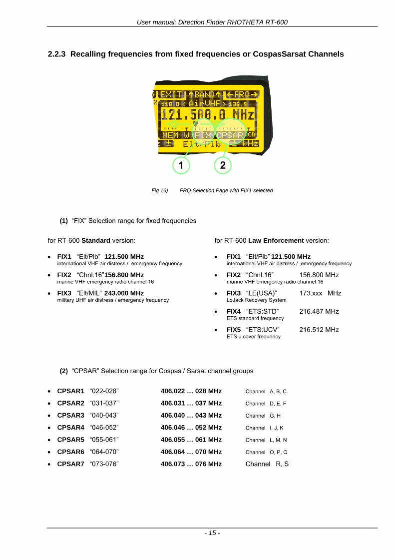
User manual Direction Finder RHOTHETA RT-600
- 15 -
223 Recalling frequencies from fixed frequencies or CospasSarsat Channels
Fig 16) FRQ Selection Page with FIX1 selected
(1) ldquoFIXrdquo Selection range for fixed frequencies
for RT-600 Standard version for RT-600 Law Enforcement version
FIX1 ldquoEltPlbrdquo 121500 MHz international VHF air distress emergency frequency
FIX2 ldquoChnl16rdquo 156800 MHz marine VHF emergency radio channel 16
FIX3 ldquoEltMILrdquo 243000 MHz military UHF air distress emergency frequency
FIX1 ldquoEltPlbrdquo 121500 MHz international VHF air distress emergency frequency
FIX2 ldquoChnl16rdquo 156800 MHz marine VHF emergency radio channel 16
FIX3 ldquoLE(USA)rdquo 173xxx MHz LoJack Recovery System
FIX4 ldquoETSSTDrdquo 216487 MHz ETS standard frequency
FIX5 ldquoETSUCVrdquo 216512 MHz ETS ucover frequency
(2) ldquoCPSARrdquo Selection range for Cospas Sarsat channel groups
CPSAR1 ldquo022-028rdquo 406022 hellip 028 MHz Channel A B C
CPSAR2 ldquo031-037rdquo 406031 hellip 037 MHz Channel D E F
CPSAR3 ldquo040-043rdquo 406040 hellip 043 MHz Channel G H
CPSAR4 ldquo046-052rdquo 406046 hellip 052 MHz Channel I J K
CPSAR5 ldquo055-061rdquo 406055 hellip 061 MHz Channel L M N
CPSAR6 ldquo064-070rdquo 406064 hellip 070 MHz Channel O P Q
CPSAR7 ldquo073-076rdquo 406073 hellip 076 MHz Channel R S
User manual Direction Finder RHOTHETA RT-600
- 16 -
224 Editing a Frequency
While on the FRQ SELECTION Page the user can directly edit the frequency displayed
Fig 17) FRQ Selection Page before frequency editing
(1) gtMHzlt Rotary switch for direct adjustment of the displayed MHz range inside the actual band
(1 x step = 1 MHz adjustment)
(2) gtkHzlt Rotary switch for changing the displayed kHz frequency according to the actual band frequency grid (as example 8333 kHz at the VHF airband)
(3) gtF2lt Adjustment of the next available band (see next page gtgt Selecting a Frequency Band)
Fig 18) FRQ Selection Page after frequency editing
If the selected and marked frequency is not one of the MEM [14] channels then the changed frequency is automatically stored in the work frequency WorkFRQ channel
User manual Direction Finder RHOTHETA RT-600
- 17 -
225 Selecting a Frequency Band
While on the FRQ Selection Page each available band can be selected by pressing F2 BAND
(1) Press push button F2 BAND for
switch over to the next band
(2) Designation of actual selected band
(3) Max frequency limits of the actual selected band (depends on wide band options)
Fig 19) FRQ Selection Page (bands)
Frequency bands availability depends on the system version (A LE) and its wide band options (F1 to F4) These optional wide bands are available if ordered in addition to the default bands Here is a listing of DEFAULT and OPTIONAL bands available with each version of the system RT-600 (STANDARD) Listing of bands
Default bands available OPTIONAL extended bands available
Band designation Frequency limits Option Designation Frequency limits
VHF Emergency Band 118000 hellip 124000 MHz gt F1 VHF Air Band 118000 hellip 136992 MHz
VHF Marine Band 154000 hellip 163000 MHz gt F2 Extended VHF Marine 137000 hellip 224995 MHz
UHF Emergency Band 240000 hellip 246000 MHz gt F3 UHF Air Band 225000 hellip 399975 MHz
COSPAS SARSAT 400000 hellip 406092 MHz
UHF FM Band 406100 hellip 410000 MHz gt F4 Additional UHF FM 406100 hellip 470000 MHz
RT-600 (Law Enforcement) Listing of bands
Default bands available OPTIONAL extended bands available
Band designation Frequency limits Option Designation Frequency limits
VHF Emergency Band 118000 hellip 124000 MHz gt F1 VHF Air Band 118000 hellip 136992 MHz
VHF Marine Band 154000 hellip 163000 MHz gt F2 Extended VHF Marine 137000 hellip 163000 MHz
LoJack 164000 hellip 174000 MHz
ETS 216000 hellip 220000 MHz
COSPAS SARSAT 400000 hellip 406092 MHz
User manual Direction Finder RHOTHETA RT-600
- 18 -
23 Direction Finder (DF) Mode Direction Finder (DF) mode is generally used to display all valid information processed by the DF from the signal received from a target transmitter The amount and kind of information displayed by the DCU depends on the type and content of the signal received and processed by the DF Simple signals such as the analog sweep-tone modulation received from a SAR beacon (ELT PLB EPIRB PDD) on 121500 MHz allow displaying only basic bearing information while digital signals such as COSPAS-SARSAT and LOJACK allow displaying more information for ex beacon IDs GPS coordinates codes VLUs etc
231 Operating Elements in DF Mode
Fig 20) Operational Elements in DF Mode
This picture shows the DCU operating in DF Mode on the international emergency frequency 121500 MHz
with an active signal being received (1) gtFREQUENCYlt Rotary switch activates the ldquoFRQrdquo frequency page for changing and selecting the
active frequency The last selected frequency remains stored after switching offon the device The selected frequency is shown on the graphic display bottom right Above additional information for the selected frequency is displayed The use of the rotary switch activates a sub-page Please refer to the Frequency Selection section for details
(2) gtVOLUMElt Rotary switch to adjust the audio output level The volume of a linked external speaker or amplifier can be adjusted in a range from 0 (off) to 99 (maximum loudness) The selected volume is shown in the bottom left corner of the graphic display The volume remains stored after switching offon the device
(3) gtSquelch Levellt adjusts the squelch level The squelch level has to be above the receiving level without signal (noise) Only signals above the squelch level are audible in the loudspeaker and used by the direction finder for bearing indication The gtSQLlt rotary switch allows to select the squelch threshold ie a minimum signal strength of an incoming signal to be processed The current settings on a signal level scale from 0 to 60 is shown in bright letters on dark background below the SQL rotary switch and as an arrow beside the signal Strength Bar-Graph
(4) The gtCLRlt Push-button is used for erasing the internal bearing value averaging store and the Last Signal Timer To activate this function the push-button has to be hold down for a minimum of circa two seconds The sophisticated averaging store increases bearing precision and enables at all an usable
User manual Direction Finder RHOTHETA RT-600
- 19 -
bearing display in case of bad receiving signals (if there is a far away transmitter andor temporary complete loss of a receiving signal) Caused by the averaging procedure a drag error may occur which might be disturbing the bearing indication after a quick change of course of the aircraft or vehicle In this case the indicated bearing value lags by the real bearing value for about two seconds (for very weak signals even longer) By pressing this push-button after a quick change of course the display will show the new bearing value without drag error Additionally the F1CLR Push-Button is used to activate specific functions high-lighted in the menu below the button by pushing it for a short time (here as example ldquoSCANrdquo starts scanning the actual air band)
(5) gtSTORElt push-button Without function except if a special function is high-lighted in the menu line of the display
(6) gtREPEATlt Push-button when pressed and hold for min 3 sec the last valid bearing value with corresponding receiving level is displayed
232 Standard Display in DF Mode
Fig 21) DF Mode
(1) gtRelative Bearing valuelt by means of a sophisticated averaging procedure a steady display is
accomplished as graphic display and as text in the range of 0deghellip 359deg (0deg corresponds to bearing direct ahead)
(2) gtSpreadlt maximum deviation of un-averaged bearing values This is an indicator of bearing quality The wider the range between the directions of maximum deviation the worse the received signal is As a result of the excellent averaging procedure even with a spread of 45deg good bearing results are achieved
(3) gtReceiving levellt (field strength) of the signal as a relative percentage value visualized as bar-graph indication and as decimal value Even without a received signal a certain noise level may be displayed
(4) gtSquelch levellt (independently adjustable and stored for each frequency band) Squelch level is indicated as marker at the Signal Strength Bar-Graph or as direct relative level value A usable bearing analysis can only be achieved if the squelch level is above the noise level (without received signal) If the antenna unit is placed close a heavily disturbing electronic devices the squelch level has to be raised thus making the direction finder being less sensitive In receive modes where the squelch level is set automatically an ldquoArdquo above the marker indicates the ldquoAutosquelchrdquo functionality
(5) gtLast Signallt timer showing the time since a signal has been received for the last time (ie since a signal has been stronger than the squelch level) Values are ldquominutes secondsrdquo
User manual Direction Finder RHOTHETA RT-600
- 20 -
233 Special Options in COSPAS-SARSAT DF Mode
Especially for the use together with beacons transmitting a data signal according to COSPAS-SARSAT specifications in the 406-MHz-Band special functionalities and pages are being provided After selection of a COSPASSARSAT Frequency (Refer to the chapter ldquoFrequency selection Pagerdquo) the bearing page provides additional information and operating options
Fig 22) Operational Elements and Display in COSPAS-SARSAT DF Mode
(1) gtAuto Squelchlt indication indicating that the squelch level is set automatically to be close to the noise
floor It is recommended to always use the Auto Squelch during COSPAS-SARSAT operation This can be achieved by manually selecting 0 (lowest possible value) or 60 (highest possible value) as squelch level During COSPAS-SARSAT-Operation this will force the automatic setting of the level
(2) gt121500lt menu option The COSPAS-SARSAT signal in the 406 MHz band is transmitted only every 50 seconds in form of a short data burst of 440 or 520 ms approaching the transmitter it will be received earlier than the 121500 MHz continuous signal due to its high transmitter power However in a lower distance to a transmitter bearing on 121500 MHz is faster thanks to the continuous or rapidly intermittent signal The 121500 MHz menu option allows a direct switch-over to 121500 MHz Direct return back from 121500 to the COSPAS-SARSAT band is possible from the 121500 MHz bearing Window in COSPAS-SARSAT mode Please refer to the chapter ldquo121500 MHz bearing Window in COSPAS-SARSAT moderdquo for details
(3) gtDecodelt menu option allows to open the COSPASSARSAT Decode sub-page by shortly pushing the F2 push-button above the menu option
(4) gtFrequency rangelt indication COSPAS-SARSAT is using a channel spacing of 3 kHz for its beacons Due to the internal architecture of the direction finder it is possible to receive more than one channel in the same time Thus frequency steps of the direction finder are 833 kHz instead of 3 kHz The receive frequency covered by the current receive frequency setting is shown in the display line above the receive frequency indication
Important If the exact frequency of the COSPAS-SARSAT beacon is unknown it is strongly recommended to use the COSPAS-SARSAT scanning functionality in order to detect the correct frequency (Refer to the chapter ldquoFrequency selection Pagerdquo amp ldquoCOSPAS-SARSAT Scan Moderdquo)
User manual Direction Finder RHOTHETA RT-600
- 21 -
234 COSPAS-SARSAT Decode Window
The COSPAS-SARSAT Decode Window allows decoding incoming COSPAS-SARSAT data messages Only while this decode window is activated the decoding is possible An already received COSPAS-SARSAT puls while DF bearing mode was activated can not be used for decoding afterwards In this case the user has to wait while this decode window is active for the next transmitted puls approx 50 sec later
Fig 23) COSPAS-SARSAT Beacon Information Page
(1) gtExitlt push button (F1 button) allows to exit the decode window and switch back to the COSPAS-
SARSAT DF Mode page
(2) gtSARSATlt in the upper right corner of the display indicates that the COSPAS-SARSAT decode function is activated
(3) gtCountrylt displays the COSPAS-SARSAT Country Code coded into the received data message
(4) gtLast Signallt time since the last COSPAS-SARSAT message has been received in minutes secondsrsquo format
(5) gtPositionlt field showing in case of location protocols being used by the beacon the encoded GNSS position data (latitude longitude) transmitted by the beacon
(6) gt15-HEX-IDlt 15-HEX-ID of the beacon in hexadecimal format
(7) gtData stringlt of the bits 25 to 112 of the COSPAS-SARSAT data burst in case of short messages and bits 25 to 144 in case of a long message format The last 8 Hex Values are separated by a blank Bit- and Frame-synchronization hex values (Bits 1 to 24) are suppressed to increase the readability of the data message
(8) gtXlt sign to indicate that the Squelch is controlled by the antenna unit for optimum sensitivity The user has no access to the Squelch setting
User manual Direction Finder RHOTHETA RT-600
- 22 -
235 Tracking 121500 MHz while in COSPAS-SARSAT Mode
While in COSPAS-SARSAT DF Mode the user can switch to 121500 MHz in order to track the beacon in VHF If a valid signal is not received in 121500 MHz the user can switch back to the last active COSPAS-SARSAT channel (406 MHz frequency) being tracking previously
Fig 24) Tracking 121500 MHz while in COSPAS-SARSAT Mode
Differences are (1) gt406xlt press F1 to switch back to the last
COSPAS-SARSAT channel (406 MHz frequency) being tracking previously
(2) gt121500 MHzlt Actual frequency being tracked
User manual Direction Finder RHOTHETA RT-600
- 23 -
236 COSPAS-SARSAT Scan Mode
If the COSPAS-SARSAT Scan Mode has been selected at the frequency selection page ldquoFRQrdquo the COSPAS-SARSAT channels as selectable manually from the Frequency Selection Page are scanned After reception of a COSPAS-SARSAT Signal the scanning is stopped at the received frequency Due to the fast scanning ndash the complete COSPAS-SARSAT sub-band is scanned within less than 400 ms ndash detection of a receivable COSPAS-SARSAT signal is possible within one COSPAS-SARSAT repetition cycle
Fig 25) FRQ Selection Page with SCN COSPAS-SARSAT Scan Page selected
At the frequency selection page an active COSPAS SARSAT scanning can be stopped by de-activating it with the rotary button (1) While the scanning is active it is also possible by pressing gtF1lt ldquoEXITrdquo to switch back to the DF pagehellip
Fig 26) DF page with active COSPAS-SARSAT Scan Mode at the DF page
(1) gtSCANlt flashing indication notifying the user that the equipment is operating in scan mode
(2) Frequency display indicating the COSPAS-SARSAT scanning frequency range
(3) gtXlt sign showing that squelch settings are controlled autonomously by the receiver
Scan mode can be left by pressing gtF1lt ldquoSTOPrdquo
User manual Direction Finder RHOTHETA RT-600
- 24 -
237 Marine Ship Scan Mode
Fig 27) DF Mode FRQ = 156800 MHz F1 for scan function
If the active frequency (2) is within the VHF Marine Band a fast scan of all ship channels is possible by pushing gtF1lt ldquoSCAN (1) In this scanning mode all marine channels 1 to 88 (156025 to 157450 MHz) are scanned continuously until a signal is received To offer the best monitoring functionality for the user also signals between to channels (4) are detected (scanning without gap) In order to prevent the scan to stop on noisy frequencies it is recommended to start scanning with high squelch settings You can reduce the squelch level in steps until the scan stops on a noisy frequency for the first time Then increase the squelch level slightly This will result in the highest possible scan sensitivity and avoiding noisy channels due to RF disturbances sometimes generated by other equipment in own aircraft
Fig 28) DF Mode active scanning in process
The scanning is stopped by pressing gtF1lt ldquoSTOPrdquo (3)
User manual Direction Finder RHOTHETA RT-600
- 25 -
24 Law Enforcement Operation Law enforcement special ops and other organizations use the RT-600 LE (LAW ENFORCEMENT) version instead of the RT-600 A (STANDARD) version One of the reasons is that the LE version features scanning and tracking of signals like LoJack and ETS as well as signals in the 216000 MHz ndash 220000 MHz band such as medical beacons wristankle transmitters cashasset recovery ldquotagsrdquo etc However the LE version shares many functions in common with the A version such as scanning and tracking in the AIR band COSPAS-SARSAT band etc
241 Power-On procedure
The power-on procedure is the same as described in 211
(1) System Version ldquo(L)rdquo for LAW ENFORCEMENT version
Fig 29) STARTUP Screen (see 211 for details)
242 LoJack Scan Mode Start scanning for a VLU Code
For the convenience of Law Enforcement and other special ops users who frequently engage in tracking SVRS (Stolen Vehicle Recovery System) signals such as LoJack (LoJack Corp FCC 9020 Part 2 SVRS) RHOTHETA has optimized the power-on procedure of the RT-600 LE version so that right after the STARTUP screen the unit displays automatically the LoJack Scan Mode page to start immediately scanning for a valid VLU (Vehicle Location Unit) code without pressing any key
Fig 30) LoJack Scan Mode unit is scanning for a LoJack VLU Code
(1) gtscan LoJacklt DF is scanning for any new LoJack VLU Code
(2) gtEXITlt press F1 to exit and switch directly to DF Mode
User manual Direction Finder RHOTHETA RT-600
- 26 -
243 LoJack Scan Mode from any other page
While operating on any page other than the LoJack Scan page the user can switch directly to LoJack Scan Mode by pressing Hotkey F2 for 2 secs
(1) press Hotkey F2 for 2 secs to switch to the LoJack Scan page
Fig 31) Hotkey F2
User manual Direction Finder RHOTHETA RT-600
- 27 -
244 Manual activation of LoJack Scan Mode
(1) select the LoJack frequency (see also Frequency Selection Page)
(2) press F1 to switch back to the DF MODE
Fig 32) FRQ Selection Page FRQ = LoJack BAND = LoJack (164-174 MHz)
While in DF MODE with adjusted LoJack frequency the user can switch directly to the LoJack Scan by pressing gtF1lt ldquoSCANrdquo
(1) press F1 SCAN to switch to the LoJack Scan page
(2) still no LoJack ID filter used (ID=off) all transmissions are received on the active frequency as example also unwanted tower pulses
Fig 33) DF Mode with LoJack filter OFF
User manual Direction Finder RHOTHETA RT-600
- 28 -
245 Receiving and accepting a new VLU Code
While in LoJack Scan Mode waiting for a VLU Code if a new VLU Code is displayed the user can accept it and switch directly to DF Mode by pressing F2
(1) a new LoJack VLU Code (0001A) has been received
(2) press F2 to accept the new VLU Code (0001A) and switch to DF MODE page with the LoJack filter activated to track only 0001A
Fig 34) LoJack Scan Mode with new VLU Code received
246 Entering a new VLU Code manually
While in LoJack Scan Mode the user can enter a LoJack VLU code also manually
(1 2 3) use the SELECTplusmn and plusmnVALUE knobs to enter a new LoJack VLU Code active ID (0001A)
(4) Press F1 to accept the new VLU Code and switch to DF Mode with the LoJack filter ON to track only 0001A
Fig 35) LoJack Scan Mode with new VLU Code entered manually
User manual Direction Finder RHOTHETA RT-600
- 29 -
247 Tracking one VLU Code while monitoring new VLU Codes
While on DF Mode and tracking a VLU Code (0001A) the user can turn the LoJack switch OFF with F2 also the user can start scanning all VLUs again with F1
0001A is displayed as the active VLU Code filter function is ON only 0001A is tracked
Monitoring of other VLU Codes is active in the background
(1) Press F1 to switch to the LoJack Scan Mode to scan for new VLU Codes
(2) Press F2 to switch LoJack filter OFF
Fig 36) DF Mode with active VLU Code and LoJack filter ON
248 Tracking one VLU Code and receiving a new VLU Code
While on DF MODE page and tracking VLU Code (0001A) in the background a new VLU Code is received and decoded (G2HC7)
(1) The new VLU Code is announced (NEW G2HC7)
(2) Press F1 to switch to LoJack Scan Mode to see the arrival time of G2HC7 and the possibility to change bearing to this new G2HC7
Fig 37) DF Mode with active VLU Code and announcement of new VLU Code
User manual Direction Finder RHOTHETA RT-600
- 30 -
249 Switching to a new VLU Code
While on the LoJack Scan Page tracking one VLU Code (0001A) and notified of a new VLU Code (G2HC7)
(1) press F1 to continue tracking 0001A
(2) press F2 to start tracking G2HC7
(3) Time elapsed since G2HC7 was last received
(4) Time elapsed since 0001A was last received
If F1 is pressed for 2 sec the indicated VLU Code (G2HC7) and ID (0001A) are deleted
Fig 38) LoJack Scan Page with one active VLU Code and one new VLU Code
2410 ldquoBlockingrdquo function of one LoJack VLU Code
The LoJack scan page can also be used to ldquoblockrdquo one unwanted LoJack VLU ID signal by separating the adjusted active ID from any other received LoJack VLU signal This is done by muting the audio (see example below) when a LoJack signal with VLU code ldquo0001Ardquo is received gtgt Any new VLU Code (active LoJack signal) - except for 0001A ndash will be displayed on the top row and generate the audible beep tone
Fig 39) LoJack Scan Page with one active VLU Code and audio OFF
Tip ldquoBlockingrdquo is an important tool for practical missions As example a stolen vehicle with VLU ID ldquo0001Ardquo was tracked in the DF bearing mode The mission
is completed but the VLU is normally still transmitting With the settings above only new VLU signals except the now unwanted ldquo0001Ardquo are audible and displayed in the upper (scan LoJack hellip for new VLU) box
User manual Direction Finder RHOTHETA RT-600
- 31 -
2411 Tracking in the 216 to 220 MHz band
The RT-600 features scanning and bearing functionality in the 216000 MHz to 220000 MHz band The 216000 MHz ndash 220000 MHz band contains frequencies and signals used by special services and tracked by law enforcement special ops and similar organizations These are some of the frequencies and services in this band
CFR 90259 tx 216000 MHz to 220000 MHz
Low Power Radio Service (LPRS) tx 216000 MHz to 217000 MHz
Medical beacons Project Lifesaver tx wristankle tx 213000 MHz to 216000 MHz
ETS tx stolen cashasset recovery tx ldquobaitrdquordquotagrdquo tx 216000 MHz to 220000 MHz tx = transmitter(s) However any future or current user of the Rhotheta RT-600 must be aware that tracking signals on the frequencies listed above may be challenging and even frustrating due mostly to negative factors in some of the transmitters
bull Very low RF power output
bull Inefficient antennas
bull Battery-powered devices with a ldquolow batteryrdquo condition
bull Devices worn or located in conditions of poor RF propagation
bull Devices with channel spacing different than the one specified for the RT-600
These factors can make it very difficult for the DF to receive the signal andor display an accurate bearing Disclaimer For the reasons explained above and even though the RT-600 features top performance in its class RHOTHETA does not offer - and is not to be held responsible for - any guaranteed minimum range or distance to a transmitter in this band
25 Setup Edit Page System settings are displayed in the setup page The functions described in this section should be used by trained personal only
Fig 40) Accessing the Setup Page
The setup page can be accessed by holding down the gtCLRlt (1) and gtREPlt (2) buttons simultaneously and in the same time performing a left-hand turn on the gtPagelt rotary switch (3)
User manual Direction Finder RHOTHETA RT-600
- 32 -
Fig 41) Setup Page
(1) gtStorelt push-button must be pressed in parallel if a value of a setting shall be modified If a value can
be modified the background stops to blink
(2) gtSelectlt rotary switch used to scroll through the menu options The value of the actually activated menu option is high-lighted with dark background and blinking
(3) gtValuelt rotary switch used to change values in menu options (gtStorelt (1) has to be pressed in parallel if a value shall be modified)
(4) gtSN-Ratiolt menu option representing the necessary Signal-To-Noise-Ratio (Difference between signal and noise level) used as criterion for the automatic squelch function Please refer to the chapter ldquoSquelch Operationrdquo for details Default value is 60 dB
(5) gtMounting Positionlt menu option to select Top- or Bottom-Mounting of the DF antenna In case of rooftop installation (eg on land vehicles) ldquoToprdquo shall be selected In case of bottom-down (upside-down) installation (eg on a helicopter) ldquoBotrdquo shall be selected If this option is not selected correctly all bearing values will be mirror-inverted
(6) gtBearing Offsetlt menu option to include a constant offset correction to the bearing indication Bearing values in degrees will be changed according to the offset value
(7) gtMaximum External Dimming Voltage for Legendslt menu option which sets the upper limit of the dimming input voltage for the legends-panel Range=[15 hellip 28]V
(8) gtMinimum External Dimming Voltage for Legendslt menu option which sets the lower limit of the dimming input voltage for the legends-panel Range=[15 hellip 28]V
(9) gtPagelt rotary switch to be turned right-hand to go back to the Direction Finder page A left-hand turn on this rotary switch will show up an additional service page with debug information used for system checks
(10) gtExtended Seriallt It is possible to enable or disable the extended serial data protocol Only of interest if serial data is used by any connected control units like moving maps or computers For detailed information see (Serial interface data protocol (short description)gt at page 46) If there are compatibility problems with already existing older remote control software it is recommended to switch OFF the extended serial data protocol
User manual Direction Finder RHOTHETA RT-600
- 33 -
3 Error messages If an internal error of the device is recognized a corresponding flashing error message will be shown in the DF pages
Fig 42) Error Messages
(1) Error message including error code (in brackets)
(2) Short description of the indicated error
In case of coincidence of various errors the error with the highest priority will be displayed
Error message Error location Reason
Error (12) VOLTDU
Main voltage supply Main Voltage input too low ( 100 V)
Error (11) NO AU
Connection antenna display or Antenna Unit
No serial data (RS485) from Antenna Unit No or damaged connection between antenna and display or damaged antenna unit
Error (10) BAD AU
Connection antenna display
Incompatibility or bad data connection between display and antenna
Error (9) BAD RU
Remote Unit Incompatibility or bad data connection between display and external serial Remote Unit or PC
Error (8) VOLTAU
Antenna Unit Voltage supply at Antenna Unit too low ( 90 V) Main voltage supply too low or considerable drop of voltage between display and antenna
Error (7) BAD DCU
Connection Display Antenna
Incompatibility or bad data connection between antenna and display
Error (6) NO DCU
Connection Display Antenna
No serial data from Display Control Unit to Antenna Unit
Error (5) PLL ERR
antenna Error in synthesizer-oscillator of receiver in Antenna Unit
Error (4) FRQ+OFS
received transmitter Received frequency too high (more than 6 KHz error of transmitter)
Error (3) FRQ-OFS
received transmitter received frequency too low (more than 6 KHZ error of transmitter)
Error (2) DECODE
radio distance transmitter DF
Data Bits of decoded signal (COSPAS-SARSAT or LoJack) defective
Error (1) DATARNG
Incompatibility of data DCU AU
Protocol data bytes out of valid range
Error (0) NO REC
Antenna Unit receiver
Receiver board defective
User manual Direction Finder RHOTHETA RT-600
- 34 -
4 Installation
41 Antenna unit A convenient position of the monopole bearing antenna is crucial for good bearing results The antenna needs an effective ground connection to the body of the aircraft or to the roof of the vehicle If there is no metallic mounting surface available a metallic sheet or similar (net) with connection to ground has to be applied first between vehicle-body and antenna In this hatched area the antenna touches the body ofthe vehicleaircraft In order to obtain a good groundconnection the surface of the body should be bared(Measuring unit [mm])
8 x holes for mounting the antenna unit to the
vehicle aircraft
Fig 43) Antenna Mounting Drawing
User manual Direction Finder RHOTHETA RT-600
- 35 -
411 Influence of antenna location and environment on the bearing accuracy
Recommendations concerning the practical antenna unit location on helicopters and airplanes
The bearing accuracy of the direction finder antenna unit is severely influenced (comparable to an airspeed sensor) by the environment For comparison a perfect high quality speed sensor will not indicate the true airspeed if this sensor is interfered by strong turbulences The direction finder antenna unit acts as a sensor for electromagnetic waves In the near field of this antenna unit any conductive (eg metallic) obstacle will influence the incoming wave field and create reflections which decrease the bearing accuracy These are general physical limitations concerning all types of direction finder systems To achieve the best bearing results it should be considered that the antenna unit is installed as far away as possible from any other vertically polarized conductive structure If possible there should be no reflectors within an area of 2-3 feet around the antenna unit In this worst case example the direction finder will not work properly
Fig 44) Antenna Installed in a Bad Location
In this example the antenna unit is located too close to the cable cutter of the helicopter This cutter will produce strong reflections especially as the length is equal to Lambda4 within the VHF airband
User manual Direction Finder RHOTHETA RT-600
- 36 -
Examples of properly installed direction finder antenna units
Fig 45) Antenna Installed in Good Locations
User manual Direction Finder RHOTHETA RT-600
- 37 -
42 Display and Control Unit
The display control unit may be mounted into a front panel by the means of this mounting drawing
Fig 46) DCU Mounting Drawing
(all dimensions in [mm]) To install or uninstall the display control unit perform the following steps (1) Remove the cover caps of the four rotary switches
(2) Loose the screws visible below the position of the cover caps
(3) Remove the plastic button from the axis of the four rotary switches
(4) Mount dismount the display control unit
(5) Re-install the plastic buttons on the axis of the four rotary switches
(6) Fix the screws so that the plastic buttons are fixed on the axis
(7) Re-install the cover caps on the four rotary switches
User manual Direction Finder RHOTHETA RT-600
- 38 -
43 System Interconnect Wiring Diagram (Also refer to chapter ldquoTechnical Datardquo for details)
Fig 47) System Interconnect Wiring Diagram
6-pol Amphenol plug femalePTG06SE10-6S(SQ)
max length of cable 20 m 9-pol Sub-D plug (femalemale)
User manual Direction Finder RHOTHETA RT-600
- 39 -
5 Technical Data
51 Electric features
Method of bearing Doppler-principle (3 kHz rotational frequency right left rotation)
Bearing accuracy1 plusmn 5deg RMS
Internal resolution 1deg
Bearing Sensitivity VHF AirEmergency le 25 μVm (typical)
VHF Marine le 25 μVm (typical)
UHF Emergency and ETS le 4 μVm (typical)
COSPAS-SARSAT le 4 μVm (typical)
LoJack Decoding (50 Message Error Rate) and bearing le 5 μVm (typical)
Frequency stability plusmn 20 ppm (Δff = plusmn210-6)
Reception frequencies
SAR version (Standard)
Frequency Options
VHF Emergency Band 118000 to 124000 MHz (833 kHz steps AM)
VHF Marine Band 154000 to 163000 MHz ( 500 kHz steps FM) (channel 16 selectable via channel no)
UHF Emergency Band 240000 to 246000 MHz (2500 kHz steps AM)
UHF FM Band 406100 to 410000 MHz ( 500 kHz steps FM)
COSPAS-SARSAT 400000 to 406092 MHz Including 406022 to 406076 MHz (Channel A S)
F1 VHF Air Band 118000 to 136992 MHz
F2 extended VHF Marine Band 137000 to 224995 MHz
F3 extended UHF Air Band 225000 to 399975 MHz
F4 additional UHF FM Band 406100 to 470000 MHz
Reception frequencies
LAW Enforcement version
Frequency Options
VHF Emergency Band 118000 to 124000 MHz (833 kHz steps AM)
VHF Marine Band 154000 to 163000 MHz (500 kHz steps FM) (channel 16 selectable via channel no)
LoJack 164000 to 174000 MHz (125 kHz steps FM)
ETS 216000 to 220000 MHz (10125 kHz AM)
COSPAS-SARSAT 400000 to 406092 MHz Including 406022 to 406076 MHz (Channel A S)
F1VHF Air Band 118000 to 136992 MHz
F2 extended VHF Marine Band 137000 to 163000 MHz
COSPAS-SARSAT fast scan mode
Full automatic detection of any active COSPAS-SARSAT channel A to S within 400 ms
COSPAS-SARSAT decoding
Reception and decoding of COSPAS-SARSAT data signal (112 or 144 bit) specified according to COSPAS-SARSAT
LoJack decoding Selectable LoJack ID display and selective active filtering
Special scanning modes
complete maritime ship band scanning within 3 s (channel 01 hellip 88 also frequencies between 2 channels are included)
1With undisturbed wave field and sufficient field strength Measuring by changing the angle of incidence with the antenna rotating on a revolving table in order to eliminate environmental influences on the results No modulation
User manual Direction Finder RHOTHETA RT-600
- 40 -
Bearable modulation A3E F3E A3X (ELT-modulation) F1D G2D COSPAS-SARSAT Bearing largely independent of modulation
Polarization Vertical
Polarization error 5deg at 60deg field vector rotation
Garbling cone Ca 30deg to the vertical
Time of response2 50 ms (with sufficient reception field strength)
LC-graphic display 128 x 64 pixels supertwist transflective extended range of temperature dark-blue display on yellow-green background background light Freely adjustable (exponential) dimming of brightness
NVG cockpit design Fully compatible NVIS Green B display Control Unit optional
Operating voltage 275 V nominal 12 V to 35 V DC
Current consumption LCD-background light Off max 500 mA (12 V DC) max 250 mA (24 V DC)
LCD-background light 100 max 750 mA (12 V DC) max 350 mA (24 V DC)
LCD-background light 100 max 900 mA (12 V DC) with NVG Option max 400 mA (24 V DC)
Audio out For external speaker approx 2 W (4 Ω)
Serial data interface Serial interface RS-232 (9600 baud 8 data bits 1 stop bit no parity)
2Very weak signals can considerably increase the time of response
User manual Direction Finder RHOTHETA RT-600
- 41 -
52 Interface External connections (optional at Sub-D 9-pol Male connector)
Dimming
Pin 8
external voltage input for variable dimming of legends
(optional)
Analog input signal for variable control of the legends illumination Input voltage range is freely adjustable in the range of 15 hellip 28 V in the setup menu Refer to chapter ldquoSetup Pagerdquo Default setting 8 hellip28 V (8 V = Off 28 V = max dimming for legends)
Input Impedance gt 50 k
Pin 6 night status line for LCD
dimming (optional)
Low-active (as example switch to ground) At input voltage lt 25 VDC the LCD dimming operates in nightNVG mode Maximum brightness ca 4 of daydefault mode brightness
Input Impedance gt 50 k
Pin 4 NVG status line for LCD
dimming (optional)
Low-active (as example switch to ground) At input voltage lt 25 VDC the LCD dimming operates in nightNVG mode Maximum brightness ca 4 of daydefault mode brightness
Input Impedance gt 50 k
AudioLF
Pin 7 Audio output signal
AC coupled voltage source with very low inner resistance Maximum output voltage ca 8 VPP = 283V RMS at maximum Volume Maximum output power ca 2 W with 4 speaker
If a headphone is connected ([32hellip600] 100mW) we recommend using a resistor (18 025 W) between audio output and headphone to prevent damage of the headphone
Serial interface RS232 (9600 baud 8 data bits 1 stop bit no parity)
Pin 3 TXD Serial output (ca plusmn10 V)
Pin 2 RXD Serial input (ca plusmn10 V)
User manual Direction Finder RHOTHETA RT-600
- 42 -
53 Mechanical features
Temperature range
Display Control Unit permissible operating temperature3 -20 degC +60 degC permissible storage temperature -30 degC +80 degC
Antenna Unit permissible operating temperature3 -40 degC +60 degC permissible storage temperature -55 degC +80 degC
Protective system Antenna Unit IP 67
Weights Display Control Unit 250 g Antenna Unit 2000 g
Dimensions Display Control Unit 82 mm x 82 mm x 43 mm (width x height x depth) Antenna Unit 270 mm x 185 mm
Fig 48) DCU Mechanical Drawing (all dimensions in [mm])
3 For temperatures lower than ndash10deg C a warm-up period of 15 min should be allowed
User manual Direction Finder RHOTHETA RT-600
- 43 -
Fig 49) AU Mechanical Drawing (all dimensions in [mm])
User manual Direction Finder RHOTHETA RT-600
- 44 -
6 Appendix
61 Frequency Ranges
User manual Direction Finder RHOTHETA RT-600
- 45 -
62 Frequencies of channels on maritime band (only for standard [A] version) Frequency-range of the RT-600 in the maritime band 156000 MHz 162025 MHz
Channel No frequency (ship - station) Frequency (coast - station)
1 156050 MHz 160650 MHz 2 156100 MHz 160700 MHz 3 156150 MHz 160750 MHz 4 156200 MHz 160800 MHz 5 156250 MHz 160850 MHz 6 156300 MHz 160900 MHz 7 156350 MHz 160950 MHz 8 156400 MHz 9 156450 MHz
10 156500 MHz 11 156550 MHz 12 156600 MHz 13 156650 MHz 14 156700 MHz 15 156750 MHz 16 156800 MHz 17 156850 MHz 18 156900 MHz 161500 MHz 19 156950 MHz 161550 MHz 20 157000 MHz 161600 MHz 21 157050 MHz 161650 MHz 22 157100 MHz 161700 MHz 23 157150 MHz 161750 MHz 24 157200 MHz 161800 MHz 25 157250 MHz 161850 MHz 26 157300 MHz 161900 MHz 27 157350 MHz 161950 MHz 28 157400 MHz 162000 MHz 60 156025 MHz 160625 MHz 61 156075 MHz 160675 MHz 62 156125 MHz 160725 MHz 63 156175 MHz 160775 MHz 64 156225 MHz 160825 MHz 65 156275 MHz 160875 MHz 66 156325 MHz 160925 MHz 67 156375 MHz 68 156425 MHz 69 156475 MHz 70 156525 MHz 71 156575 MHz 72 156625 MHz 73 156675 MHz 74 156725 MHz 75 156775 MHz 76 156825 MHz 77 156875 MHz 78 156925 MHz 161525 MHz 79 156975 MHz 161575 MHz 80 157025 MHz 161625 MHz 81 157075 MHz 161675 MHz 82 157125 MHz 161725 MHz 83 157175 MHz 161775 MHz 84 157225 MHz 161825 MHz 85 157275 MHz 161875 MHz 86 157325 MHz 161925 MHz 87 157375 MHz 161975 MHz 88 157425 MHz 162025 MHz
User manual Direction Finder RHOTHETA RT-600
- 46 -
63 Serial interface data protocol (short description)
631 General
Interface parameters RS232 9600 Baud 8 databits 1 stopbit no parity LSB sent first Timing of serial data For accurate use of the serial data (even for the optional serial input commands) the correct timing is mandatory The DCU (Display Control Unit) sends out via the RS-232 Pins (see 43 System Interconnect Wiring Diagram page 38) cyclic and autonomous every approx 250300 ms a binary data stream which contains all relevant DF-bearing information The output data contains one or two blocks of binary data (see next picture with accordingly description) The optional serial input is only used if changes (as example frequency change) are done by additional remote control units
Fig 50) Timing of serial data
Serial standard output
This output data is always available and contains all relevant DF-bearing data For detailed content see page 47
Optional extended serial output
This data contains some additional information like as example CospasSarsat or LoJack decoding and ID data For detailed content see page 50 The data is only available with DCU Software [Rev ge 320] and if this optional data block is configured as ON = enabled (see Setup Edit Page point (10) )
Even to avoid compatibility problems with already existing older remote control software it is possible to disable switch off this additional data block (see Setup Edit Page point (10) )
Optional serial input
Only used for optional commands to control DCU parameters If as example the direction finder frequency is changed remotely there is send to the DCU one time this data block with the new frequency For detailed content see page 52
User manual Direction Finder RHOTHETA RT-600
- 47 -
632 Serial standard output (protocol description)
Specification serial standard output
The binary data stream with a length of 39 bytes starts with a header byte (value = hex 0xA0 as ID for DF Mode) The next bytes contain different values for status bearing information and also service The last byte is used for data stream checksum control Remark This is a binary data protocol So every byte value from 0dec hellip 255dec (0x00 hellip 0xFF) is possible Because of this it is not allowed to realize a start byte detection by the content (0xA0) The idle line detection is recommended for detection the end of message Register of databytes (for details see next page)
byte no
[0] Header = 0xA0 Id for DF Mode
[1] Number = 39 = bytes in the complete message (including header and checksumbyte)
[2] Status (1) HSB [x|x|x|x|x|x|x|x] LSB | | | | | | | --gt (0) Receiving | | | | | | ----gt (1) Squelch controlled by AU (X) | | | | | ------gt (2) Permission RL Calibration | | | | --------gt (3) Line Night | | | ----------gt (4) Line NVG | | ------------gt (5) Dimming External | --------------gt (6) Autosquelch Active ----------------gt (7) 0=Standard Version 1=LE Version
[3] Status (2) HSB [x|x|x|x|x|x|x|x] LSB | ----------------gt (7) 0=Standard 1=extended serial dataprotocol = ONactive
[45] Error (Bits[120])
[6] Actual DCU Page
[7] Volume [0hellip100]
[811] Frequency [Hz]
[12] Active Band
[13] Actual Squelchlevel [0hellip60]
[14] Audio-Line amp_NF_Test Output
[15] (Not used)
[1617] Voltage_DCU ([0hellip335]=[0 hellip 335]V
[1819] Voltage_AU ([0hellip255]=[0 hellip 255]V
[20] Temperature_AU [-68hellip+127]degC
[21] Frequency Offset [-99hellip+99]
[2225] ServiceTest values (mode dependent test values for service only)
26 (Not used reserved)
[27] Level [0hellip100]
[2829] Bearing Averaged [0hellip359]deg relative
[3031] Bearing Live_Min [0hellip359]deg relative
[3233] Bearing Live_Max [0hellip359]deg relative
[34] Test Value PS-RAM Right Rotation[0hellip178] (for service only)
[35] Test Value PS-RAM Left Rotation [0hellip178] (for service only)
[3637] (Not used reserved)
[38] Checksum is the 2rsquos complement of the modulo-256 sum of all bytes without checksum-byte [0n-1]
User manual Direction Finder RHOTHETA RT-600
- 48 -
Detailed Description of important values for practical use
Status byte [2] Receiving Bit 0 of this value (LSB) indicates signal receiving Bit 0 = 0 then no signal is received and so on no bearing is available Bit 0 = 1 then bearing is possible Bit 1 if(1) then Squelch is controlled by AU (active at modes CospasSarsat Decode CospasSarsat Scanning LoJack with Filter=ID only)
Error bytes [4hellip5] 16 bit value each set bit corresponds to the error no (Refer to the chapter Error messages) Example - 0x0000 No error - 0x0800 Bit No 11 Set ( = No AU Error)
Actual DCU Page byte [6] indicates actual operating mode of DCU 0 = Standard bearing page 1 = Frequency memory page 2 = CospasSarsat decoding page 3 = LoJack decoding page (ID edit)
Frequency bytes [8hellip11] 32 bit value actual adjusted frequency [Hz] Example - 0x073DF160 1215000000 121500 MHz
Active Band Standard Version [A] 0=VHF Airband 1=VHF Marineband sea 2=VHF Marineband coast 3=UHV Airband 4=CospasSarsat LE Version [L] 0=VHF Airband 1=LoJack 2=Lifesaver 3=ETS 4=CospasSarsat
Actual Squelchlevel byte [13] Range [0hellip60] without signal the actual squelchlevel should always be adjusted a little bit over the noise level (Refer to the chapter Squelch operation)
Level byte [27] Range [099] actual receiving level (without signal this value is equal to the noise level) If a signal is received then this value corresponds to the signal strength of this signal
Relative Bearing averaged byte [2829] 16 bit value Range [0hellip359 0xFFFF] if the value = 0xFFFF then no valid bearing is available otherwise this value contains the actual averaged bearing information in Deg [0deg359deg] Example - 0X0114 276deg bearing (= left side oriented to heading)
Bearing Live MinMax byte[3031] amp [3233] - 16 bit values Range [0hellip359 0xFFFF] Only for signal quality or additional information ndash NOT recommended for bearing indication The relative live bearing field contains the maxmin bearing in degrees without averaging The relative live bearing reacts faster than the normal relative bearing but it has not the precision of the averaged bearing The MinMax Bearing Values are calculated within a time period of approx 250 ms If they are very close together (for example ldquo124rdquo and ldquo128rdquo degrees) then the signal quality is quite good A wide span of the minmax values (for example ldquo97rdquo and ldquo162rdquo) shows very noisy but nevertheless bearable signal quality
User manual Direction Finder RHOTHETA RT-600
- 49 -
633 DCU Info output (protocol description)
Specification DCU Info output
Remark This protocol is only available while the SetupEdit page is activated at the DCU
byte no
[0] Header = 0xAF Id for DCU Info Mode
[1] Number = 39 = bytes in the complete message (including header and checksumbyte)
[2]
(see standard output) [3]
[45]
[621] Info String of 15 byteschars the string contains Information about Unit Variant Software Version and Serial No
Example Byte [318] =
|--AU ID---||Var-||---Software Version---| |-------------- Serial No---------------| [0x44][0x55][0x41][0x33][0x2E][0x33][0x30][0x3A][0x20][0x20][0x30][0x31][0x32][0x33][0x34][0x00] rsquoDrsquo rsquoUrsquo rsquoArsquo rsquo3rsquo rsquorsquo rsquo3rsquo rsquo0rsquo rsquorsquo rsquo rsquo rsquo rsquo rsquo0rsquo rsquo1rsquo rsquo2rsquo rsquo3rsquo rsquo4rsquo rsquoENDrsquo | | | | __________________ | | ________________________ | n n n | | n n n n n | (Software Version) | | (Serial No) | gt rsquoArsquo = Standard Variant gt rsquoLrsquo = Law Enforcement Variant
User manual Direction Finder RHOTHETA RT-600
- 50 -
634 Optional extended serial output (protocol description)
The data content depends on the actual mode of the direction finder To get special data the direction finder has first to be switched to the equivalent mode
COSPAS-SARSAT Decoding data
This data is only available and valid if Display Control Unit with actual software Rev ge 320 (see Power-On procedure page 10) Configuration of Extended serial = ON (see Setup Edit Page point (10) ) Direction Finder COSPAS-SARSAT decoding mode is activated by selecting the corresponding page
(see COSPAS-SARSAT Decode Window page 20 and page 21) and so on Header (byte 0 of data) = 0x91
A valid COSPAS-SARSAT decoding data protocol is always marked by the first data byte (header = 0x91) Always after receiving and decoding of a valid COSPAS-SARSAT pulse the complete data protocol with 33 bytes is send out one time
Byte No
[0] Header = 0x91 (Identification for CPSarsat decoding mode)
[1] Number of bytes - 7 if no decoded pulse is available - 33 if new pulse was received and is available
[2] Error
[3] Bit[0] - 0 =gt No new 406 MSG (decoded data) available - 1 =gt New valid 406 MSG available (Sync amp Frame Ok) Check Error Status for Bit-Errors
Bit[61] AutoSquelch Level valid range [060] ( decimal)
Bit[7] = 1 Squelch controlled by AU
[4] Signallevel of received signal valid range [099] ( decimal)
[5] Voltage of Antenna Unit Power Supply input valid range [80255] (decimal = 80 255 V DC)
[6] Temperature inside Antenna Unit valid range [-50+100] (degC signed byte value)
The following databytes are only available if a correct CPSarsat puls gets received and decoded with correct checksum
[724] 18 x Databytes complete orginal CPSarsat 406 decoded message (144 bit)
Databyte Nr [ Byte 7 ] [ Byte 8 ] [Byte9 Byte24] 406 MSG Bit Nr [1 2 3 4 5 6 7 8] [9 10 11 12 13 14 15 16] [17 144]
[25] SN-Flag valid values 0x53=rsquoSrsquo 0x4E=rsquoNrsquo 0x2D=rsquo-rsquo if no GPS data available
GPS-Position Latitude
[26] Deg valid values [090] (decimal Deg) 0xFF if no GPS data available
[27] Min valid values [059] (decimal Deg) 0xFF if no GPS data available
[28] Sec valid values [059] (decimal Deg) 0xFF if no GPS data available
[29] WE-Flag valid values 0x57=rsquoWrsquo 0x45=rsquoErsquo 0x2D=rsquo-rsquo if no GPS data available
GPS-Position Longitude
[30] Deg valid values [0180] (decimal Deg) 0xFF if no GPS data available
[31] Min valid values [059] (decimal Deg) 0xFF if no GPS data available
[32] Sec valid values [059] (decimal Deg) 0xFF if no GPS data available
User manual Direction Finder RHOTHETA RT-600
- 51 -
LoJack ID data
This data is only available and valid if Display Control Unit with actual software Rev ge 320 (see Power-On procedure page 10) Direction Finder of variant [L] Law Enforcement Configuration of Extended serial = ON (see Setup Edit Page point (10) ) Direction Finder is working with active LoJack gtID Filterlt Header (byte 0 of data) = 0x93 or 0x94
Valid LoJack ID decoding data is always marked by the first data byte (header = 0x93 or 0x94)
Byte No
[0] Header = 0x93 LoJack ID editing sub-page is selected Filter = VLU all valid and received LoJack pulses are indicated = 0x94 Lojack Decode amp DF Mode with active Filter = ID
[1] Number of bytes in the complete data stream - decimal 26 = default value
[2] Nonrelevant
[3] Bit[0] Receiving OnOff - 0 =gt No Receiving no bearing - 1 =gt new LoJack pulse received
[412] Nonrelevant
[1317] Lojack ID
Replay Code 5 x ASCII Chars ldquoNo BIOZrdquo set
Example ASCII = ldquo000R1rdquo
18 Receiver Level Out Max [099]
19
LoJack Decoder Status [07] - 0 Off - 1 Wait for Preamble - 2 Preamble Ok - 3 FlagPattern Ok - 4 Data BitError gt 1 - 5 Data Ok (No VLU) - 6 VLU Ok - 7 ID Ok (Filter=IDONLY)
[2025] Nonrelevant
Remark Only if byte no [3] bit [0] gets ldquo1rdquo (Receiving On) then an active LoJack pulse is received and so on the corresponding LoJack ID valid otherwise the LoJack ID only shows the actual adjusted LoJack Filter ID of the direction finder
User manual Direction Finder RHOTHETA RT-600
- 52 -
635 Optional serial input (protocol description)
Specification serial input (optional)
The serial input is normally used for service and maintenance only Nevertheless it is possible via this interface to remote control the actual frequency and the squelchlevel of the DF system If a valid data stream is send to the DF then the actual frequency selection at the DCU is switched to Block2 AUX0 At this memory channel the new frequency is stored and used automatically (Refer to the chapter Frequency Selection Page) If the frequency is changed (by one valid data stream) no more serial input is necessary The actual frequency can be changed again at any time by manual operation at the DCU The timing of serial input (if used) is strictly fixed The optional serial input has to take place directly after a complete serial output (max 50 ms delay time) If a new changed frequency is commanded to the DCU via this serial input interface it can take up to 1 sec of time until this new frequency is ready for operationbearing It is strictly not recommended to use the frequency remote control for any scan mode The frequency control has to be used for static frequency change only Register of databytes
byte no
[0] Header 0xC0
[1] Number of bytes in the complete message (including header and checksumbyte)
[23] (not used for normal operation any byte values allowed)
[4] Volume [0100]
[58] Frequency [Hz] (frequency is rounded to the according grid automatically)
Valid Range for Standard Version Valid Range for LE Version
118000000 hellip 123000000 [Hz] 8333 kHz 118000000 hellip 123000000 [Hz] 8333 kHz
156050000 hellip 162025000 [Hz] 5000 kHz 164000000 hellip 174000000 [Hz] 8333 kHz
201000000 hellip 215995000 [Hz] 5000 kHz
240000000 hellip 246000000 [Hz] 8333 kHz 216000000 hellip 218995000 [Hz] 12500 kHz219000000 hellip 220000000 [Hz] 10000 kHz
400000000 hellip 410000000 [Hz] 8333 kHz 400000000 hellip 410000000 [Hz] 8333 kHz
[9] Squelchlevel Manual = [0hellip60] Autosql= [ -1] Warning use only for pulsed signals (as example CpSarsat LoJack)
[10] (not used for normal operation any byte values allowed)
[11] Internal Dimming [0100]
[12] Checksum is the 2rsquos complement of the modulo-256 sum of all bytes without checksum-byte [0n-1]
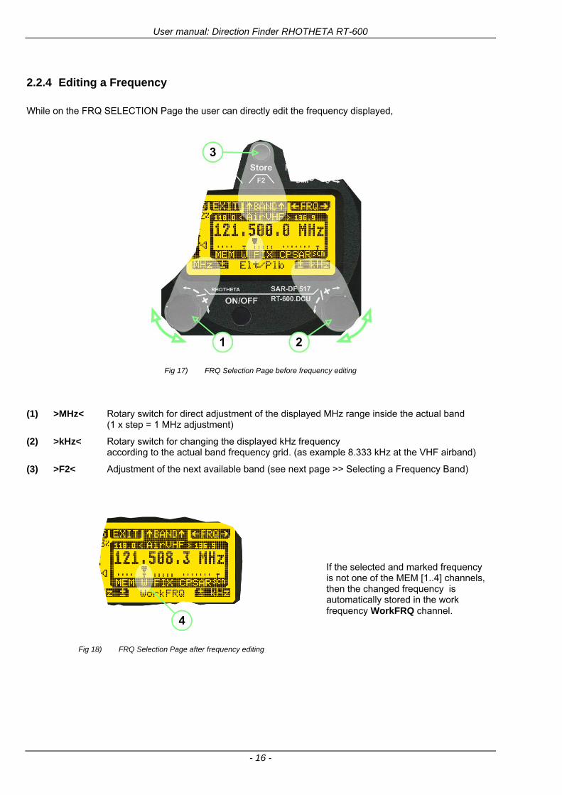
User manual Direction Finder RHOTHETA RT-600
- 16 -
224 Editing a Frequency
While on the FRQ SELECTION Page the user can directly edit the frequency displayed
Fig 17) FRQ Selection Page before frequency editing
(1) gtMHzlt Rotary switch for direct adjustment of the displayed MHz range inside the actual band
(1 x step = 1 MHz adjustment)
(2) gtkHzlt Rotary switch for changing the displayed kHz frequency according to the actual band frequency grid (as example 8333 kHz at the VHF airband)
(3) gtF2lt Adjustment of the next available band (see next page gtgt Selecting a Frequency Band)
Fig 18) FRQ Selection Page after frequency editing
If the selected and marked frequency is not one of the MEM [14] channels then the changed frequency is automatically stored in the work frequency WorkFRQ channel
User manual Direction Finder RHOTHETA RT-600
- 17 -
225 Selecting a Frequency Band
While on the FRQ Selection Page each available band can be selected by pressing F2 BAND
(1) Press push button F2 BAND for
switch over to the next band
(2) Designation of actual selected band
(3) Max frequency limits of the actual selected band (depends on wide band options)
Fig 19) FRQ Selection Page (bands)
Frequency bands availability depends on the system version (A LE) and its wide band options (F1 to F4) These optional wide bands are available if ordered in addition to the default bands Here is a listing of DEFAULT and OPTIONAL bands available with each version of the system RT-600 (STANDARD) Listing of bands
Default bands available OPTIONAL extended bands available
Band designation Frequency limits Option Designation Frequency limits
VHF Emergency Band 118000 hellip 124000 MHz gt F1 VHF Air Band 118000 hellip 136992 MHz
VHF Marine Band 154000 hellip 163000 MHz gt F2 Extended VHF Marine 137000 hellip 224995 MHz
UHF Emergency Band 240000 hellip 246000 MHz gt F3 UHF Air Band 225000 hellip 399975 MHz
COSPAS SARSAT 400000 hellip 406092 MHz
UHF FM Band 406100 hellip 410000 MHz gt F4 Additional UHF FM 406100 hellip 470000 MHz
RT-600 (Law Enforcement) Listing of bands
Default bands available OPTIONAL extended bands available
Band designation Frequency limits Option Designation Frequency limits
VHF Emergency Band 118000 hellip 124000 MHz gt F1 VHF Air Band 118000 hellip 136992 MHz
VHF Marine Band 154000 hellip 163000 MHz gt F2 Extended VHF Marine 137000 hellip 163000 MHz
LoJack 164000 hellip 174000 MHz
ETS 216000 hellip 220000 MHz
COSPAS SARSAT 400000 hellip 406092 MHz
User manual Direction Finder RHOTHETA RT-600
- 18 -
23 Direction Finder (DF) Mode Direction Finder (DF) mode is generally used to display all valid information processed by the DF from the signal received from a target transmitter The amount and kind of information displayed by the DCU depends on the type and content of the signal received and processed by the DF Simple signals such as the analog sweep-tone modulation received from a SAR beacon (ELT PLB EPIRB PDD) on 121500 MHz allow displaying only basic bearing information while digital signals such as COSPAS-SARSAT and LOJACK allow displaying more information for ex beacon IDs GPS coordinates codes VLUs etc
231 Operating Elements in DF Mode
Fig 20) Operational Elements in DF Mode
This picture shows the DCU operating in DF Mode on the international emergency frequency 121500 MHz
with an active signal being received (1) gtFREQUENCYlt Rotary switch activates the ldquoFRQrdquo frequency page for changing and selecting the
active frequency The last selected frequency remains stored after switching offon the device The selected frequency is shown on the graphic display bottom right Above additional information for the selected frequency is displayed The use of the rotary switch activates a sub-page Please refer to the Frequency Selection section for details
(2) gtVOLUMElt Rotary switch to adjust the audio output level The volume of a linked external speaker or amplifier can be adjusted in a range from 0 (off) to 99 (maximum loudness) The selected volume is shown in the bottom left corner of the graphic display The volume remains stored after switching offon the device
(3) gtSquelch Levellt adjusts the squelch level The squelch level has to be above the receiving level without signal (noise) Only signals above the squelch level are audible in the loudspeaker and used by the direction finder for bearing indication The gtSQLlt rotary switch allows to select the squelch threshold ie a minimum signal strength of an incoming signal to be processed The current settings on a signal level scale from 0 to 60 is shown in bright letters on dark background below the SQL rotary switch and as an arrow beside the signal Strength Bar-Graph
(4) The gtCLRlt Push-button is used for erasing the internal bearing value averaging store and the Last Signal Timer To activate this function the push-button has to be hold down for a minimum of circa two seconds The sophisticated averaging store increases bearing precision and enables at all an usable
User manual Direction Finder RHOTHETA RT-600
- 19 -
bearing display in case of bad receiving signals (if there is a far away transmitter andor temporary complete loss of a receiving signal) Caused by the averaging procedure a drag error may occur which might be disturbing the bearing indication after a quick change of course of the aircraft or vehicle In this case the indicated bearing value lags by the real bearing value for about two seconds (for very weak signals even longer) By pressing this push-button after a quick change of course the display will show the new bearing value without drag error Additionally the F1CLR Push-Button is used to activate specific functions high-lighted in the menu below the button by pushing it for a short time (here as example ldquoSCANrdquo starts scanning the actual air band)
(5) gtSTORElt push-button Without function except if a special function is high-lighted in the menu line of the display
(6) gtREPEATlt Push-button when pressed and hold for min 3 sec the last valid bearing value with corresponding receiving level is displayed
232 Standard Display in DF Mode
Fig 21) DF Mode
(1) gtRelative Bearing valuelt by means of a sophisticated averaging procedure a steady display is
accomplished as graphic display and as text in the range of 0deghellip 359deg (0deg corresponds to bearing direct ahead)
(2) gtSpreadlt maximum deviation of un-averaged bearing values This is an indicator of bearing quality The wider the range between the directions of maximum deviation the worse the received signal is As a result of the excellent averaging procedure even with a spread of 45deg good bearing results are achieved
(3) gtReceiving levellt (field strength) of the signal as a relative percentage value visualized as bar-graph indication and as decimal value Even without a received signal a certain noise level may be displayed
(4) gtSquelch levellt (independently adjustable and stored for each frequency band) Squelch level is indicated as marker at the Signal Strength Bar-Graph or as direct relative level value A usable bearing analysis can only be achieved if the squelch level is above the noise level (without received signal) If the antenna unit is placed close a heavily disturbing electronic devices the squelch level has to be raised thus making the direction finder being less sensitive In receive modes where the squelch level is set automatically an ldquoArdquo above the marker indicates the ldquoAutosquelchrdquo functionality
(5) gtLast Signallt timer showing the time since a signal has been received for the last time (ie since a signal has been stronger than the squelch level) Values are ldquominutes secondsrdquo
User manual Direction Finder RHOTHETA RT-600
- 20 -
233 Special Options in COSPAS-SARSAT DF Mode
Especially for the use together with beacons transmitting a data signal according to COSPAS-SARSAT specifications in the 406-MHz-Band special functionalities and pages are being provided After selection of a COSPASSARSAT Frequency (Refer to the chapter ldquoFrequency selection Pagerdquo) the bearing page provides additional information and operating options
Fig 22) Operational Elements and Display in COSPAS-SARSAT DF Mode
(1) gtAuto Squelchlt indication indicating that the squelch level is set automatically to be close to the noise
floor It is recommended to always use the Auto Squelch during COSPAS-SARSAT operation This can be achieved by manually selecting 0 (lowest possible value) or 60 (highest possible value) as squelch level During COSPAS-SARSAT-Operation this will force the automatic setting of the level
(2) gt121500lt menu option The COSPAS-SARSAT signal in the 406 MHz band is transmitted only every 50 seconds in form of a short data burst of 440 or 520 ms approaching the transmitter it will be received earlier than the 121500 MHz continuous signal due to its high transmitter power However in a lower distance to a transmitter bearing on 121500 MHz is faster thanks to the continuous or rapidly intermittent signal The 121500 MHz menu option allows a direct switch-over to 121500 MHz Direct return back from 121500 to the COSPAS-SARSAT band is possible from the 121500 MHz bearing Window in COSPAS-SARSAT mode Please refer to the chapter ldquo121500 MHz bearing Window in COSPAS-SARSAT moderdquo for details
(3) gtDecodelt menu option allows to open the COSPASSARSAT Decode sub-page by shortly pushing the F2 push-button above the menu option
(4) gtFrequency rangelt indication COSPAS-SARSAT is using a channel spacing of 3 kHz for its beacons Due to the internal architecture of the direction finder it is possible to receive more than one channel in the same time Thus frequency steps of the direction finder are 833 kHz instead of 3 kHz The receive frequency covered by the current receive frequency setting is shown in the display line above the receive frequency indication
Important If the exact frequency of the COSPAS-SARSAT beacon is unknown it is strongly recommended to use the COSPAS-SARSAT scanning functionality in order to detect the correct frequency (Refer to the chapter ldquoFrequency selection Pagerdquo amp ldquoCOSPAS-SARSAT Scan Moderdquo)
User manual Direction Finder RHOTHETA RT-600
- 21 -
234 COSPAS-SARSAT Decode Window
The COSPAS-SARSAT Decode Window allows decoding incoming COSPAS-SARSAT data messages Only while this decode window is activated the decoding is possible An already received COSPAS-SARSAT puls while DF bearing mode was activated can not be used for decoding afterwards In this case the user has to wait while this decode window is active for the next transmitted puls approx 50 sec later
Fig 23) COSPAS-SARSAT Beacon Information Page
(1) gtExitlt push button (F1 button) allows to exit the decode window and switch back to the COSPAS-
SARSAT DF Mode page
(2) gtSARSATlt in the upper right corner of the display indicates that the COSPAS-SARSAT decode function is activated
(3) gtCountrylt displays the COSPAS-SARSAT Country Code coded into the received data message
(4) gtLast Signallt time since the last COSPAS-SARSAT message has been received in minutes secondsrsquo format
(5) gtPositionlt field showing in case of location protocols being used by the beacon the encoded GNSS position data (latitude longitude) transmitted by the beacon
(6) gt15-HEX-IDlt 15-HEX-ID of the beacon in hexadecimal format
(7) gtData stringlt of the bits 25 to 112 of the COSPAS-SARSAT data burst in case of short messages and bits 25 to 144 in case of a long message format The last 8 Hex Values are separated by a blank Bit- and Frame-synchronization hex values (Bits 1 to 24) are suppressed to increase the readability of the data message
(8) gtXlt sign to indicate that the Squelch is controlled by the antenna unit for optimum sensitivity The user has no access to the Squelch setting
User manual Direction Finder RHOTHETA RT-600
- 22 -
235 Tracking 121500 MHz while in COSPAS-SARSAT Mode
While in COSPAS-SARSAT DF Mode the user can switch to 121500 MHz in order to track the beacon in VHF If a valid signal is not received in 121500 MHz the user can switch back to the last active COSPAS-SARSAT channel (406 MHz frequency) being tracking previously
Fig 24) Tracking 121500 MHz while in COSPAS-SARSAT Mode
Differences are (1) gt406xlt press F1 to switch back to the last
COSPAS-SARSAT channel (406 MHz frequency) being tracking previously
(2) gt121500 MHzlt Actual frequency being tracked
User manual Direction Finder RHOTHETA RT-600
- 23 -
236 COSPAS-SARSAT Scan Mode
If the COSPAS-SARSAT Scan Mode has been selected at the frequency selection page ldquoFRQrdquo the COSPAS-SARSAT channels as selectable manually from the Frequency Selection Page are scanned After reception of a COSPAS-SARSAT Signal the scanning is stopped at the received frequency Due to the fast scanning ndash the complete COSPAS-SARSAT sub-band is scanned within less than 400 ms ndash detection of a receivable COSPAS-SARSAT signal is possible within one COSPAS-SARSAT repetition cycle
Fig 25) FRQ Selection Page with SCN COSPAS-SARSAT Scan Page selected
At the frequency selection page an active COSPAS SARSAT scanning can be stopped by de-activating it with the rotary button (1) While the scanning is active it is also possible by pressing gtF1lt ldquoEXITrdquo to switch back to the DF pagehellip
Fig 26) DF page with active COSPAS-SARSAT Scan Mode at the DF page
(1) gtSCANlt flashing indication notifying the user that the equipment is operating in scan mode
(2) Frequency display indicating the COSPAS-SARSAT scanning frequency range
(3) gtXlt sign showing that squelch settings are controlled autonomously by the receiver
Scan mode can be left by pressing gtF1lt ldquoSTOPrdquo
User manual Direction Finder RHOTHETA RT-600
- 24 -
237 Marine Ship Scan Mode
Fig 27) DF Mode FRQ = 156800 MHz F1 for scan function
If the active frequency (2) is within the VHF Marine Band a fast scan of all ship channels is possible by pushing gtF1lt ldquoSCAN (1) In this scanning mode all marine channels 1 to 88 (156025 to 157450 MHz) are scanned continuously until a signal is received To offer the best monitoring functionality for the user also signals between to channels (4) are detected (scanning without gap) In order to prevent the scan to stop on noisy frequencies it is recommended to start scanning with high squelch settings You can reduce the squelch level in steps until the scan stops on a noisy frequency for the first time Then increase the squelch level slightly This will result in the highest possible scan sensitivity and avoiding noisy channels due to RF disturbances sometimes generated by other equipment in own aircraft
Fig 28) DF Mode active scanning in process
The scanning is stopped by pressing gtF1lt ldquoSTOPrdquo (3)
User manual Direction Finder RHOTHETA RT-600
- 25 -
24 Law Enforcement Operation Law enforcement special ops and other organizations use the RT-600 LE (LAW ENFORCEMENT) version instead of the RT-600 A (STANDARD) version One of the reasons is that the LE version features scanning and tracking of signals like LoJack and ETS as well as signals in the 216000 MHz ndash 220000 MHz band such as medical beacons wristankle transmitters cashasset recovery ldquotagsrdquo etc However the LE version shares many functions in common with the A version such as scanning and tracking in the AIR band COSPAS-SARSAT band etc
241 Power-On procedure
The power-on procedure is the same as described in 211
(1) System Version ldquo(L)rdquo for LAW ENFORCEMENT version
Fig 29) STARTUP Screen (see 211 for details)
242 LoJack Scan Mode Start scanning for a VLU Code
For the convenience of Law Enforcement and other special ops users who frequently engage in tracking SVRS (Stolen Vehicle Recovery System) signals such as LoJack (LoJack Corp FCC 9020 Part 2 SVRS) RHOTHETA has optimized the power-on procedure of the RT-600 LE version so that right after the STARTUP screen the unit displays automatically the LoJack Scan Mode page to start immediately scanning for a valid VLU (Vehicle Location Unit) code without pressing any key
Fig 30) LoJack Scan Mode unit is scanning for a LoJack VLU Code
(1) gtscan LoJacklt DF is scanning for any new LoJack VLU Code
(2) gtEXITlt press F1 to exit and switch directly to DF Mode
User manual Direction Finder RHOTHETA RT-600
- 26 -
243 LoJack Scan Mode from any other page
While operating on any page other than the LoJack Scan page the user can switch directly to LoJack Scan Mode by pressing Hotkey F2 for 2 secs
(1) press Hotkey F2 for 2 secs to switch to the LoJack Scan page
Fig 31) Hotkey F2
User manual Direction Finder RHOTHETA RT-600
- 27 -
244 Manual activation of LoJack Scan Mode
(1) select the LoJack frequency (see also Frequency Selection Page)
(2) press F1 to switch back to the DF MODE
Fig 32) FRQ Selection Page FRQ = LoJack BAND = LoJack (164-174 MHz)
While in DF MODE with adjusted LoJack frequency the user can switch directly to the LoJack Scan by pressing gtF1lt ldquoSCANrdquo
(1) press F1 SCAN to switch to the LoJack Scan page
(2) still no LoJack ID filter used (ID=off) all transmissions are received on the active frequency as example also unwanted tower pulses
Fig 33) DF Mode with LoJack filter OFF
User manual Direction Finder RHOTHETA RT-600
- 28 -
245 Receiving and accepting a new VLU Code
While in LoJack Scan Mode waiting for a VLU Code if a new VLU Code is displayed the user can accept it and switch directly to DF Mode by pressing F2
(1) a new LoJack VLU Code (0001A) has been received
(2) press F2 to accept the new VLU Code (0001A) and switch to DF MODE page with the LoJack filter activated to track only 0001A
Fig 34) LoJack Scan Mode with new VLU Code received
246 Entering a new VLU Code manually
While in LoJack Scan Mode the user can enter a LoJack VLU code also manually
(1 2 3) use the SELECTplusmn and plusmnVALUE knobs to enter a new LoJack VLU Code active ID (0001A)
(4) Press F1 to accept the new VLU Code and switch to DF Mode with the LoJack filter ON to track only 0001A
Fig 35) LoJack Scan Mode with new VLU Code entered manually
User manual Direction Finder RHOTHETA RT-600
- 29 -
247 Tracking one VLU Code while monitoring new VLU Codes
While on DF Mode and tracking a VLU Code (0001A) the user can turn the LoJack switch OFF with F2 also the user can start scanning all VLUs again with F1
0001A is displayed as the active VLU Code filter function is ON only 0001A is tracked
Monitoring of other VLU Codes is active in the background
(1) Press F1 to switch to the LoJack Scan Mode to scan for new VLU Codes
(2) Press F2 to switch LoJack filter OFF
Fig 36) DF Mode with active VLU Code and LoJack filter ON
248 Tracking one VLU Code and receiving a new VLU Code
While on DF MODE page and tracking VLU Code (0001A) in the background a new VLU Code is received and decoded (G2HC7)
(1) The new VLU Code is announced (NEW G2HC7)
(2) Press F1 to switch to LoJack Scan Mode to see the arrival time of G2HC7 and the possibility to change bearing to this new G2HC7
Fig 37) DF Mode with active VLU Code and announcement of new VLU Code
User manual Direction Finder RHOTHETA RT-600
- 30 -
249 Switching to a new VLU Code
While on the LoJack Scan Page tracking one VLU Code (0001A) and notified of a new VLU Code (G2HC7)
(1) press F1 to continue tracking 0001A
(2) press F2 to start tracking G2HC7
(3) Time elapsed since G2HC7 was last received
(4) Time elapsed since 0001A was last received
If F1 is pressed for 2 sec the indicated VLU Code (G2HC7) and ID (0001A) are deleted
Fig 38) LoJack Scan Page with one active VLU Code and one new VLU Code
2410 ldquoBlockingrdquo function of one LoJack VLU Code
The LoJack scan page can also be used to ldquoblockrdquo one unwanted LoJack VLU ID signal by separating the adjusted active ID from any other received LoJack VLU signal This is done by muting the audio (see example below) when a LoJack signal with VLU code ldquo0001Ardquo is received gtgt Any new VLU Code (active LoJack signal) - except for 0001A ndash will be displayed on the top row and generate the audible beep tone
Fig 39) LoJack Scan Page with one active VLU Code and audio OFF
Tip ldquoBlockingrdquo is an important tool for practical missions As example a stolen vehicle with VLU ID ldquo0001Ardquo was tracked in the DF bearing mode The mission
is completed but the VLU is normally still transmitting With the settings above only new VLU signals except the now unwanted ldquo0001Ardquo are audible and displayed in the upper (scan LoJack hellip for new VLU) box
User manual Direction Finder RHOTHETA RT-600
- 31 -
2411 Tracking in the 216 to 220 MHz band
The RT-600 features scanning and bearing functionality in the 216000 MHz to 220000 MHz band The 216000 MHz ndash 220000 MHz band contains frequencies and signals used by special services and tracked by law enforcement special ops and similar organizations These are some of the frequencies and services in this band
CFR 90259 tx 216000 MHz to 220000 MHz
Low Power Radio Service (LPRS) tx 216000 MHz to 217000 MHz
Medical beacons Project Lifesaver tx wristankle tx 213000 MHz to 216000 MHz
ETS tx stolen cashasset recovery tx ldquobaitrdquordquotagrdquo tx 216000 MHz to 220000 MHz tx = transmitter(s) However any future or current user of the Rhotheta RT-600 must be aware that tracking signals on the frequencies listed above may be challenging and even frustrating due mostly to negative factors in some of the transmitters
bull Very low RF power output
bull Inefficient antennas
bull Battery-powered devices with a ldquolow batteryrdquo condition
bull Devices worn or located in conditions of poor RF propagation
bull Devices with channel spacing different than the one specified for the RT-600
These factors can make it very difficult for the DF to receive the signal andor display an accurate bearing Disclaimer For the reasons explained above and even though the RT-600 features top performance in its class RHOTHETA does not offer - and is not to be held responsible for - any guaranteed minimum range or distance to a transmitter in this band
25 Setup Edit Page System settings are displayed in the setup page The functions described in this section should be used by trained personal only
Fig 40) Accessing the Setup Page
The setup page can be accessed by holding down the gtCLRlt (1) and gtREPlt (2) buttons simultaneously and in the same time performing a left-hand turn on the gtPagelt rotary switch (3)
User manual Direction Finder RHOTHETA RT-600
- 32 -
Fig 41) Setup Page
(1) gtStorelt push-button must be pressed in parallel if a value of a setting shall be modified If a value can
be modified the background stops to blink
(2) gtSelectlt rotary switch used to scroll through the menu options The value of the actually activated menu option is high-lighted with dark background and blinking
(3) gtValuelt rotary switch used to change values in menu options (gtStorelt (1) has to be pressed in parallel if a value shall be modified)
(4) gtSN-Ratiolt menu option representing the necessary Signal-To-Noise-Ratio (Difference between signal and noise level) used as criterion for the automatic squelch function Please refer to the chapter ldquoSquelch Operationrdquo for details Default value is 60 dB
(5) gtMounting Positionlt menu option to select Top- or Bottom-Mounting of the DF antenna In case of rooftop installation (eg on land vehicles) ldquoToprdquo shall be selected In case of bottom-down (upside-down) installation (eg on a helicopter) ldquoBotrdquo shall be selected If this option is not selected correctly all bearing values will be mirror-inverted
(6) gtBearing Offsetlt menu option to include a constant offset correction to the bearing indication Bearing values in degrees will be changed according to the offset value
(7) gtMaximum External Dimming Voltage for Legendslt menu option which sets the upper limit of the dimming input voltage for the legends-panel Range=[15 hellip 28]V
(8) gtMinimum External Dimming Voltage for Legendslt menu option which sets the lower limit of the dimming input voltage for the legends-panel Range=[15 hellip 28]V
(9) gtPagelt rotary switch to be turned right-hand to go back to the Direction Finder page A left-hand turn on this rotary switch will show up an additional service page with debug information used for system checks
(10) gtExtended Seriallt It is possible to enable or disable the extended serial data protocol Only of interest if serial data is used by any connected control units like moving maps or computers For detailed information see (Serial interface data protocol (short description)gt at page 46) If there are compatibility problems with already existing older remote control software it is recommended to switch OFF the extended serial data protocol
User manual Direction Finder RHOTHETA RT-600
- 33 -
3 Error messages If an internal error of the device is recognized a corresponding flashing error message will be shown in the DF pages
Fig 42) Error Messages
(1) Error message including error code (in brackets)
(2) Short description of the indicated error
In case of coincidence of various errors the error with the highest priority will be displayed
Error message Error location Reason
Error (12) VOLTDU
Main voltage supply Main Voltage input too low ( 100 V)
Error (11) NO AU
Connection antenna display or Antenna Unit
No serial data (RS485) from Antenna Unit No or damaged connection between antenna and display or damaged antenna unit
Error (10) BAD AU
Connection antenna display
Incompatibility or bad data connection between display and antenna
Error (9) BAD RU
Remote Unit Incompatibility or bad data connection between display and external serial Remote Unit or PC
Error (8) VOLTAU
Antenna Unit Voltage supply at Antenna Unit too low ( 90 V) Main voltage supply too low or considerable drop of voltage between display and antenna
Error (7) BAD DCU
Connection Display Antenna
Incompatibility or bad data connection between antenna and display
Error (6) NO DCU
Connection Display Antenna
No serial data from Display Control Unit to Antenna Unit
Error (5) PLL ERR
antenna Error in synthesizer-oscillator of receiver in Antenna Unit
Error (4) FRQ+OFS
received transmitter Received frequency too high (more than 6 KHz error of transmitter)
Error (3) FRQ-OFS
received transmitter received frequency too low (more than 6 KHZ error of transmitter)
Error (2) DECODE
radio distance transmitter DF
Data Bits of decoded signal (COSPAS-SARSAT or LoJack) defective
Error (1) DATARNG
Incompatibility of data DCU AU
Protocol data bytes out of valid range
Error (0) NO REC
Antenna Unit receiver
Receiver board defective
User manual Direction Finder RHOTHETA RT-600
- 34 -
4 Installation
41 Antenna unit A convenient position of the monopole bearing antenna is crucial for good bearing results The antenna needs an effective ground connection to the body of the aircraft or to the roof of the vehicle If there is no metallic mounting surface available a metallic sheet or similar (net) with connection to ground has to be applied first between vehicle-body and antenna In this hatched area the antenna touches the body ofthe vehicleaircraft In order to obtain a good groundconnection the surface of the body should be bared(Measuring unit [mm])
8 x holes for mounting the antenna unit to the
vehicle aircraft
Fig 43) Antenna Mounting Drawing
User manual Direction Finder RHOTHETA RT-600
- 35 -
411 Influence of antenna location and environment on the bearing accuracy
Recommendations concerning the practical antenna unit location on helicopters and airplanes
The bearing accuracy of the direction finder antenna unit is severely influenced (comparable to an airspeed sensor) by the environment For comparison a perfect high quality speed sensor will not indicate the true airspeed if this sensor is interfered by strong turbulences The direction finder antenna unit acts as a sensor for electromagnetic waves In the near field of this antenna unit any conductive (eg metallic) obstacle will influence the incoming wave field and create reflections which decrease the bearing accuracy These are general physical limitations concerning all types of direction finder systems To achieve the best bearing results it should be considered that the antenna unit is installed as far away as possible from any other vertically polarized conductive structure If possible there should be no reflectors within an area of 2-3 feet around the antenna unit In this worst case example the direction finder will not work properly
Fig 44) Antenna Installed in a Bad Location
In this example the antenna unit is located too close to the cable cutter of the helicopter This cutter will produce strong reflections especially as the length is equal to Lambda4 within the VHF airband
User manual Direction Finder RHOTHETA RT-600
- 36 -
Examples of properly installed direction finder antenna units
Fig 45) Antenna Installed in Good Locations
User manual Direction Finder RHOTHETA RT-600
- 37 -
42 Display and Control Unit
The display control unit may be mounted into a front panel by the means of this mounting drawing
Fig 46) DCU Mounting Drawing
(all dimensions in [mm]) To install or uninstall the display control unit perform the following steps (1) Remove the cover caps of the four rotary switches
(2) Loose the screws visible below the position of the cover caps
(3) Remove the plastic button from the axis of the four rotary switches
(4) Mount dismount the display control unit
(5) Re-install the plastic buttons on the axis of the four rotary switches
(6) Fix the screws so that the plastic buttons are fixed on the axis
(7) Re-install the cover caps on the four rotary switches
User manual Direction Finder RHOTHETA RT-600
- 38 -
43 System Interconnect Wiring Diagram (Also refer to chapter ldquoTechnical Datardquo for details)
Fig 47) System Interconnect Wiring Diagram
6-pol Amphenol plug femalePTG06SE10-6S(SQ)
max length of cable 20 m 9-pol Sub-D plug (femalemale)
User manual Direction Finder RHOTHETA RT-600
- 39 -
5 Technical Data
51 Electric features
Method of bearing Doppler-principle (3 kHz rotational frequency right left rotation)
Bearing accuracy1 plusmn 5deg RMS
Internal resolution 1deg
Bearing Sensitivity VHF AirEmergency le 25 μVm (typical)
VHF Marine le 25 μVm (typical)
UHF Emergency and ETS le 4 μVm (typical)
COSPAS-SARSAT le 4 μVm (typical)
LoJack Decoding (50 Message Error Rate) and bearing le 5 μVm (typical)
Frequency stability plusmn 20 ppm (Δff = plusmn210-6)
Reception frequencies
SAR version (Standard)
Frequency Options
VHF Emergency Band 118000 to 124000 MHz (833 kHz steps AM)
VHF Marine Band 154000 to 163000 MHz ( 500 kHz steps FM) (channel 16 selectable via channel no)
UHF Emergency Band 240000 to 246000 MHz (2500 kHz steps AM)
UHF FM Band 406100 to 410000 MHz ( 500 kHz steps FM)
COSPAS-SARSAT 400000 to 406092 MHz Including 406022 to 406076 MHz (Channel A S)
F1 VHF Air Band 118000 to 136992 MHz
F2 extended VHF Marine Band 137000 to 224995 MHz
F3 extended UHF Air Band 225000 to 399975 MHz
F4 additional UHF FM Band 406100 to 470000 MHz
Reception frequencies
LAW Enforcement version
Frequency Options
VHF Emergency Band 118000 to 124000 MHz (833 kHz steps AM)
VHF Marine Band 154000 to 163000 MHz (500 kHz steps FM) (channel 16 selectable via channel no)
LoJack 164000 to 174000 MHz (125 kHz steps FM)
ETS 216000 to 220000 MHz (10125 kHz AM)
COSPAS-SARSAT 400000 to 406092 MHz Including 406022 to 406076 MHz (Channel A S)
F1VHF Air Band 118000 to 136992 MHz
F2 extended VHF Marine Band 137000 to 163000 MHz
COSPAS-SARSAT fast scan mode
Full automatic detection of any active COSPAS-SARSAT channel A to S within 400 ms
COSPAS-SARSAT decoding
Reception and decoding of COSPAS-SARSAT data signal (112 or 144 bit) specified according to COSPAS-SARSAT
LoJack decoding Selectable LoJack ID display and selective active filtering
Special scanning modes
complete maritime ship band scanning within 3 s (channel 01 hellip 88 also frequencies between 2 channels are included)
1With undisturbed wave field and sufficient field strength Measuring by changing the angle of incidence with the antenna rotating on a revolving table in order to eliminate environmental influences on the results No modulation
User manual Direction Finder RHOTHETA RT-600
- 40 -
Bearable modulation A3E F3E A3X (ELT-modulation) F1D G2D COSPAS-SARSAT Bearing largely independent of modulation
Polarization Vertical
Polarization error 5deg at 60deg field vector rotation
Garbling cone Ca 30deg to the vertical
Time of response2 50 ms (with sufficient reception field strength)
LC-graphic display 128 x 64 pixels supertwist transflective extended range of temperature dark-blue display on yellow-green background background light Freely adjustable (exponential) dimming of brightness
NVG cockpit design Fully compatible NVIS Green B display Control Unit optional
Operating voltage 275 V nominal 12 V to 35 V DC
Current consumption LCD-background light Off max 500 mA (12 V DC) max 250 mA (24 V DC)
LCD-background light 100 max 750 mA (12 V DC) max 350 mA (24 V DC)
LCD-background light 100 max 900 mA (12 V DC) with NVG Option max 400 mA (24 V DC)
Audio out For external speaker approx 2 W (4 Ω)
Serial data interface Serial interface RS-232 (9600 baud 8 data bits 1 stop bit no parity)
2Very weak signals can considerably increase the time of response
User manual Direction Finder RHOTHETA RT-600
- 41 -
52 Interface External connections (optional at Sub-D 9-pol Male connector)
Dimming
Pin 8
external voltage input for variable dimming of legends
(optional)
Analog input signal for variable control of the legends illumination Input voltage range is freely adjustable in the range of 15 hellip 28 V in the setup menu Refer to chapter ldquoSetup Pagerdquo Default setting 8 hellip28 V (8 V = Off 28 V = max dimming for legends)
Input Impedance gt 50 k
Pin 6 night status line for LCD
dimming (optional)
Low-active (as example switch to ground) At input voltage lt 25 VDC the LCD dimming operates in nightNVG mode Maximum brightness ca 4 of daydefault mode brightness
Input Impedance gt 50 k
Pin 4 NVG status line for LCD
dimming (optional)
Low-active (as example switch to ground) At input voltage lt 25 VDC the LCD dimming operates in nightNVG mode Maximum brightness ca 4 of daydefault mode brightness
Input Impedance gt 50 k
AudioLF
Pin 7 Audio output signal
AC coupled voltage source with very low inner resistance Maximum output voltage ca 8 VPP = 283V RMS at maximum Volume Maximum output power ca 2 W with 4 speaker
If a headphone is connected ([32hellip600] 100mW) we recommend using a resistor (18 025 W) between audio output and headphone to prevent damage of the headphone
Serial interface RS232 (9600 baud 8 data bits 1 stop bit no parity)
Pin 3 TXD Serial output (ca plusmn10 V)
Pin 2 RXD Serial input (ca plusmn10 V)
User manual Direction Finder RHOTHETA RT-600
- 42 -
53 Mechanical features
Temperature range
Display Control Unit permissible operating temperature3 -20 degC +60 degC permissible storage temperature -30 degC +80 degC
Antenna Unit permissible operating temperature3 -40 degC +60 degC permissible storage temperature -55 degC +80 degC
Protective system Antenna Unit IP 67
Weights Display Control Unit 250 g Antenna Unit 2000 g
Dimensions Display Control Unit 82 mm x 82 mm x 43 mm (width x height x depth) Antenna Unit 270 mm x 185 mm
Fig 48) DCU Mechanical Drawing (all dimensions in [mm])
3 For temperatures lower than ndash10deg C a warm-up period of 15 min should be allowed
User manual Direction Finder RHOTHETA RT-600
- 43 -
Fig 49) AU Mechanical Drawing (all dimensions in [mm])
User manual Direction Finder RHOTHETA RT-600
- 44 -
6 Appendix
61 Frequency Ranges
User manual Direction Finder RHOTHETA RT-600
- 45 -
62 Frequencies of channels on maritime band (only for standard [A] version) Frequency-range of the RT-600 in the maritime band 156000 MHz 162025 MHz
Channel No frequency (ship - station) Frequency (coast - station)
1 156050 MHz 160650 MHz 2 156100 MHz 160700 MHz 3 156150 MHz 160750 MHz 4 156200 MHz 160800 MHz 5 156250 MHz 160850 MHz 6 156300 MHz 160900 MHz 7 156350 MHz 160950 MHz 8 156400 MHz 9 156450 MHz
10 156500 MHz 11 156550 MHz 12 156600 MHz 13 156650 MHz 14 156700 MHz 15 156750 MHz 16 156800 MHz 17 156850 MHz 18 156900 MHz 161500 MHz 19 156950 MHz 161550 MHz 20 157000 MHz 161600 MHz 21 157050 MHz 161650 MHz 22 157100 MHz 161700 MHz 23 157150 MHz 161750 MHz 24 157200 MHz 161800 MHz 25 157250 MHz 161850 MHz 26 157300 MHz 161900 MHz 27 157350 MHz 161950 MHz 28 157400 MHz 162000 MHz 60 156025 MHz 160625 MHz 61 156075 MHz 160675 MHz 62 156125 MHz 160725 MHz 63 156175 MHz 160775 MHz 64 156225 MHz 160825 MHz 65 156275 MHz 160875 MHz 66 156325 MHz 160925 MHz 67 156375 MHz 68 156425 MHz 69 156475 MHz 70 156525 MHz 71 156575 MHz 72 156625 MHz 73 156675 MHz 74 156725 MHz 75 156775 MHz 76 156825 MHz 77 156875 MHz 78 156925 MHz 161525 MHz 79 156975 MHz 161575 MHz 80 157025 MHz 161625 MHz 81 157075 MHz 161675 MHz 82 157125 MHz 161725 MHz 83 157175 MHz 161775 MHz 84 157225 MHz 161825 MHz 85 157275 MHz 161875 MHz 86 157325 MHz 161925 MHz 87 157375 MHz 161975 MHz 88 157425 MHz 162025 MHz
User manual Direction Finder RHOTHETA RT-600
- 46 -
63 Serial interface data protocol (short description)
631 General
Interface parameters RS232 9600 Baud 8 databits 1 stopbit no parity LSB sent first Timing of serial data For accurate use of the serial data (even for the optional serial input commands) the correct timing is mandatory The DCU (Display Control Unit) sends out via the RS-232 Pins (see 43 System Interconnect Wiring Diagram page 38) cyclic and autonomous every approx 250300 ms a binary data stream which contains all relevant DF-bearing information The output data contains one or two blocks of binary data (see next picture with accordingly description) The optional serial input is only used if changes (as example frequency change) are done by additional remote control units
Fig 50) Timing of serial data
Serial standard output
This output data is always available and contains all relevant DF-bearing data For detailed content see page 47
Optional extended serial output
This data contains some additional information like as example CospasSarsat or LoJack decoding and ID data For detailed content see page 50 The data is only available with DCU Software [Rev ge 320] and if this optional data block is configured as ON = enabled (see Setup Edit Page point (10) )
Even to avoid compatibility problems with already existing older remote control software it is possible to disable switch off this additional data block (see Setup Edit Page point (10) )
Optional serial input
Only used for optional commands to control DCU parameters If as example the direction finder frequency is changed remotely there is send to the DCU one time this data block with the new frequency For detailed content see page 52
User manual Direction Finder RHOTHETA RT-600
- 47 -
632 Serial standard output (protocol description)
Specification serial standard output
The binary data stream with a length of 39 bytes starts with a header byte (value = hex 0xA0 as ID for DF Mode) The next bytes contain different values for status bearing information and also service The last byte is used for data stream checksum control Remark This is a binary data protocol So every byte value from 0dec hellip 255dec (0x00 hellip 0xFF) is possible Because of this it is not allowed to realize a start byte detection by the content (0xA0) The idle line detection is recommended for detection the end of message Register of databytes (for details see next page)
byte no
[0] Header = 0xA0 Id for DF Mode
[1] Number = 39 = bytes in the complete message (including header and checksumbyte)
[2] Status (1) HSB [x|x|x|x|x|x|x|x] LSB | | | | | | | --gt (0) Receiving | | | | | | ----gt (1) Squelch controlled by AU (X) | | | | | ------gt (2) Permission RL Calibration | | | | --------gt (3) Line Night | | | ----------gt (4) Line NVG | | ------------gt (5) Dimming External | --------------gt (6) Autosquelch Active ----------------gt (7) 0=Standard Version 1=LE Version
[3] Status (2) HSB [x|x|x|x|x|x|x|x] LSB | ----------------gt (7) 0=Standard 1=extended serial dataprotocol = ONactive
[45] Error (Bits[120])
[6] Actual DCU Page
[7] Volume [0hellip100]
[811] Frequency [Hz]
[12] Active Band
[13] Actual Squelchlevel [0hellip60]
[14] Audio-Line amp_NF_Test Output
[15] (Not used)
[1617] Voltage_DCU ([0hellip335]=[0 hellip 335]V
[1819] Voltage_AU ([0hellip255]=[0 hellip 255]V
[20] Temperature_AU [-68hellip+127]degC
[21] Frequency Offset [-99hellip+99]
[2225] ServiceTest values (mode dependent test values for service only)
26 (Not used reserved)
[27] Level [0hellip100]
[2829] Bearing Averaged [0hellip359]deg relative
[3031] Bearing Live_Min [0hellip359]deg relative
[3233] Bearing Live_Max [0hellip359]deg relative
[34] Test Value PS-RAM Right Rotation[0hellip178] (for service only)
[35] Test Value PS-RAM Left Rotation [0hellip178] (for service only)
[3637] (Not used reserved)
[38] Checksum is the 2rsquos complement of the modulo-256 sum of all bytes without checksum-byte [0n-1]
User manual Direction Finder RHOTHETA RT-600
- 48 -
Detailed Description of important values for practical use
Status byte [2] Receiving Bit 0 of this value (LSB) indicates signal receiving Bit 0 = 0 then no signal is received and so on no bearing is available Bit 0 = 1 then bearing is possible Bit 1 if(1) then Squelch is controlled by AU (active at modes CospasSarsat Decode CospasSarsat Scanning LoJack with Filter=ID only)
Error bytes [4hellip5] 16 bit value each set bit corresponds to the error no (Refer to the chapter Error messages) Example - 0x0000 No error - 0x0800 Bit No 11 Set ( = No AU Error)
Actual DCU Page byte [6] indicates actual operating mode of DCU 0 = Standard bearing page 1 = Frequency memory page 2 = CospasSarsat decoding page 3 = LoJack decoding page (ID edit)
Frequency bytes [8hellip11] 32 bit value actual adjusted frequency [Hz] Example - 0x073DF160 1215000000 121500 MHz
Active Band Standard Version [A] 0=VHF Airband 1=VHF Marineband sea 2=VHF Marineband coast 3=UHV Airband 4=CospasSarsat LE Version [L] 0=VHF Airband 1=LoJack 2=Lifesaver 3=ETS 4=CospasSarsat
Actual Squelchlevel byte [13] Range [0hellip60] without signal the actual squelchlevel should always be adjusted a little bit over the noise level (Refer to the chapter Squelch operation)
Level byte [27] Range [099] actual receiving level (without signal this value is equal to the noise level) If a signal is received then this value corresponds to the signal strength of this signal
Relative Bearing averaged byte [2829] 16 bit value Range [0hellip359 0xFFFF] if the value = 0xFFFF then no valid bearing is available otherwise this value contains the actual averaged bearing information in Deg [0deg359deg] Example - 0X0114 276deg bearing (= left side oriented to heading)
Bearing Live MinMax byte[3031] amp [3233] - 16 bit values Range [0hellip359 0xFFFF] Only for signal quality or additional information ndash NOT recommended for bearing indication The relative live bearing field contains the maxmin bearing in degrees without averaging The relative live bearing reacts faster than the normal relative bearing but it has not the precision of the averaged bearing The MinMax Bearing Values are calculated within a time period of approx 250 ms If they are very close together (for example ldquo124rdquo and ldquo128rdquo degrees) then the signal quality is quite good A wide span of the minmax values (for example ldquo97rdquo and ldquo162rdquo) shows very noisy but nevertheless bearable signal quality
User manual Direction Finder RHOTHETA RT-600
- 49 -
633 DCU Info output (protocol description)
Specification DCU Info output
Remark This protocol is only available while the SetupEdit page is activated at the DCU
byte no
[0] Header = 0xAF Id for DCU Info Mode
[1] Number = 39 = bytes in the complete message (including header and checksumbyte)
[2]
(see standard output) [3]
[45]
[621] Info String of 15 byteschars the string contains Information about Unit Variant Software Version and Serial No
Example Byte [318] =
|--AU ID---||Var-||---Software Version---| |-------------- Serial No---------------| [0x44][0x55][0x41][0x33][0x2E][0x33][0x30][0x3A][0x20][0x20][0x30][0x31][0x32][0x33][0x34][0x00] rsquoDrsquo rsquoUrsquo rsquoArsquo rsquo3rsquo rsquorsquo rsquo3rsquo rsquo0rsquo rsquorsquo rsquo rsquo rsquo rsquo rsquo0rsquo rsquo1rsquo rsquo2rsquo rsquo3rsquo rsquo4rsquo rsquoENDrsquo | | | | __________________ | | ________________________ | n n n | | n n n n n | (Software Version) | | (Serial No) | gt rsquoArsquo = Standard Variant gt rsquoLrsquo = Law Enforcement Variant
User manual Direction Finder RHOTHETA RT-600
- 50 -
634 Optional extended serial output (protocol description)
The data content depends on the actual mode of the direction finder To get special data the direction finder has first to be switched to the equivalent mode
COSPAS-SARSAT Decoding data
This data is only available and valid if Display Control Unit with actual software Rev ge 320 (see Power-On procedure page 10) Configuration of Extended serial = ON (see Setup Edit Page point (10) ) Direction Finder COSPAS-SARSAT decoding mode is activated by selecting the corresponding page
(see COSPAS-SARSAT Decode Window page 20 and page 21) and so on Header (byte 0 of data) = 0x91
A valid COSPAS-SARSAT decoding data protocol is always marked by the first data byte (header = 0x91) Always after receiving and decoding of a valid COSPAS-SARSAT pulse the complete data protocol with 33 bytes is send out one time
Byte No
[0] Header = 0x91 (Identification for CPSarsat decoding mode)
[1] Number of bytes - 7 if no decoded pulse is available - 33 if new pulse was received and is available
[2] Error
[3] Bit[0] - 0 =gt No new 406 MSG (decoded data) available - 1 =gt New valid 406 MSG available (Sync amp Frame Ok) Check Error Status for Bit-Errors
Bit[61] AutoSquelch Level valid range [060] ( decimal)
Bit[7] = 1 Squelch controlled by AU
[4] Signallevel of received signal valid range [099] ( decimal)
[5] Voltage of Antenna Unit Power Supply input valid range [80255] (decimal = 80 255 V DC)
[6] Temperature inside Antenna Unit valid range [-50+100] (degC signed byte value)
The following databytes are only available if a correct CPSarsat puls gets received and decoded with correct checksum
[724] 18 x Databytes complete orginal CPSarsat 406 decoded message (144 bit)
Databyte Nr [ Byte 7 ] [ Byte 8 ] [Byte9 Byte24] 406 MSG Bit Nr [1 2 3 4 5 6 7 8] [9 10 11 12 13 14 15 16] [17 144]
[25] SN-Flag valid values 0x53=rsquoSrsquo 0x4E=rsquoNrsquo 0x2D=rsquo-rsquo if no GPS data available
GPS-Position Latitude
[26] Deg valid values [090] (decimal Deg) 0xFF if no GPS data available
[27] Min valid values [059] (decimal Deg) 0xFF if no GPS data available
[28] Sec valid values [059] (decimal Deg) 0xFF if no GPS data available
[29] WE-Flag valid values 0x57=rsquoWrsquo 0x45=rsquoErsquo 0x2D=rsquo-rsquo if no GPS data available
GPS-Position Longitude
[30] Deg valid values [0180] (decimal Deg) 0xFF if no GPS data available
[31] Min valid values [059] (decimal Deg) 0xFF if no GPS data available
[32] Sec valid values [059] (decimal Deg) 0xFF if no GPS data available
User manual Direction Finder RHOTHETA RT-600
- 51 -
LoJack ID data
This data is only available and valid if Display Control Unit with actual software Rev ge 320 (see Power-On procedure page 10) Direction Finder of variant [L] Law Enforcement Configuration of Extended serial = ON (see Setup Edit Page point (10) ) Direction Finder is working with active LoJack gtID Filterlt Header (byte 0 of data) = 0x93 or 0x94
Valid LoJack ID decoding data is always marked by the first data byte (header = 0x93 or 0x94)
Byte No
[0] Header = 0x93 LoJack ID editing sub-page is selected Filter = VLU all valid and received LoJack pulses are indicated = 0x94 Lojack Decode amp DF Mode with active Filter = ID
[1] Number of bytes in the complete data stream - decimal 26 = default value
[2] Nonrelevant
[3] Bit[0] Receiving OnOff - 0 =gt No Receiving no bearing - 1 =gt new LoJack pulse received
[412] Nonrelevant
[1317] Lojack ID
Replay Code 5 x ASCII Chars ldquoNo BIOZrdquo set
Example ASCII = ldquo000R1rdquo
18 Receiver Level Out Max [099]
19
LoJack Decoder Status [07] - 0 Off - 1 Wait for Preamble - 2 Preamble Ok - 3 FlagPattern Ok - 4 Data BitError gt 1 - 5 Data Ok (No VLU) - 6 VLU Ok - 7 ID Ok (Filter=IDONLY)
[2025] Nonrelevant
Remark Only if byte no [3] bit [0] gets ldquo1rdquo (Receiving On) then an active LoJack pulse is received and so on the corresponding LoJack ID valid otherwise the LoJack ID only shows the actual adjusted LoJack Filter ID of the direction finder
User manual Direction Finder RHOTHETA RT-600
- 52 -
635 Optional serial input (protocol description)
Specification serial input (optional)
The serial input is normally used for service and maintenance only Nevertheless it is possible via this interface to remote control the actual frequency and the squelchlevel of the DF system If a valid data stream is send to the DF then the actual frequency selection at the DCU is switched to Block2 AUX0 At this memory channel the new frequency is stored and used automatically (Refer to the chapter Frequency Selection Page) If the frequency is changed (by one valid data stream) no more serial input is necessary The actual frequency can be changed again at any time by manual operation at the DCU The timing of serial input (if used) is strictly fixed The optional serial input has to take place directly after a complete serial output (max 50 ms delay time) If a new changed frequency is commanded to the DCU via this serial input interface it can take up to 1 sec of time until this new frequency is ready for operationbearing It is strictly not recommended to use the frequency remote control for any scan mode The frequency control has to be used for static frequency change only Register of databytes
byte no
[0] Header 0xC0
[1] Number of bytes in the complete message (including header and checksumbyte)
[23] (not used for normal operation any byte values allowed)
[4] Volume [0100]
[58] Frequency [Hz] (frequency is rounded to the according grid automatically)
Valid Range for Standard Version Valid Range for LE Version
118000000 hellip 123000000 [Hz] 8333 kHz 118000000 hellip 123000000 [Hz] 8333 kHz
156050000 hellip 162025000 [Hz] 5000 kHz 164000000 hellip 174000000 [Hz] 8333 kHz
201000000 hellip 215995000 [Hz] 5000 kHz
240000000 hellip 246000000 [Hz] 8333 kHz 216000000 hellip 218995000 [Hz] 12500 kHz219000000 hellip 220000000 [Hz] 10000 kHz
400000000 hellip 410000000 [Hz] 8333 kHz 400000000 hellip 410000000 [Hz] 8333 kHz
[9] Squelchlevel Manual = [0hellip60] Autosql= [ -1] Warning use only for pulsed signals (as example CpSarsat LoJack)
[10] (not used for normal operation any byte values allowed)
[11] Internal Dimming [0100]
[12] Checksum is the 2rsquos complement of the modulo-256 sum of all bytes without checksum-byte [0n-1]
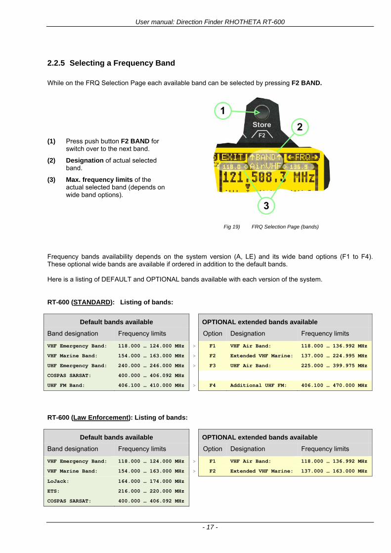
User manual Direction Finder RHOTHETA RT-600
- 17 -
225 Selecting a Frequency Band
While on the FRQ Selection Page each available band can be selected by pressing F2 BAND
(1) Press push button F2 BAND for
switch over to the next band
(2) Designation of actual selected band
(3) Max frequency limits of the actual selected band (depends on wide band options)
Fig 19) FRQ Selection Page (bands)
Frequency bands availability depends on the system version (A LE) and its wide band options (F1 to F4) These optional wide bands are available if ordered in addition to the default bands Here is a listing of DEFAULT and OPTIONAL bands available with each version of the system RT-600 (STANDARD) Listing of bands
Default bands available OPTIONAL extended bands available
Band designation Frequency limits Option Designation Frequency limits
VHF Emergency Band 118000 hellip 124000 MHz gt F1 VHF Air Band 118000 hellip 136992 MHz
VHF Marine Band 154000 hellip 163000 MHz gt F2 Extended VHF Marine 137000 hellip 224995 MHz
UHF Emergency Band 240000 hellip 246000 MHz gt F3 UHF Air Band 225000 hellip 399975 MHz
COSPAS SARSAT 400000 hellip 406092 MHz
UHF FM Band 406100 hellip 410000 MHz gt F4 Additional UHF FM 406100 hellip 470000 MHz
RT-600 (Law Enforcement) Listing of bands
Default bands available OPTIONAL extended bands available
Band designation Frequency limits Option Designation Frequency limits
VHF Emergency Band 118000 hellip 124000 MHz gt F1 VHF Air Band 118000 hellip 136992 MHz
VHF Marine Band 154000 hellip 163000 MHz gt F2 Extended VHF Marine 137000 hellip 163000 MHz
LoJack 164000 hellip 174000 MHz
ETS 216000 hellip 220000 MHz
COSPAS SARSAT 400000 hellip 406092 MHz
User manual Direction Finder RHOTHETA RT-600
- 18 -
23 Direction Finder (DF) Mode Direction Finder (DF) mode is generally used to display all valid information processed by the DF from the signal received from a target transmitter The amount and kind of information displayed by the DCU depends on the type and content of the signal received and processed by the DF Simple signals such as the analog sweep-tone modulation received from a SAR beacon (ELT PLB EPIRB PDD) on 121500 MHz allow displaying only basic bearing information while digital signals such as COSPAS-SARSAT and LOJACK allow displaying more information for ex beacon IDs GPS coordinates codes VLUs etc
231 Operating Elements in DF Mode
Fig 20) Operational Elements in DF Mode
This picture shows the DCU operating in DF Mode on the international emergency frequency 121500 MHz
with an active signal being received (1) gtFREQUENCYlt Rotary switch activates the ldquoFRQrdquo frequency page for changing and selecting the
active frequency The last selected frequency remains stored after switching offon the device The selected frequency is shown on the graphic display bottom right Above additional information for the selected frequency is displayed The use of the rotary switch activates a sub-page Please refer to the Frequency Selection section for details
(2) gtVOLUMElt Rotary switch to adjust the audio output level The volume of a linked external speaker or amplifier can be adjusted in a range from 0 (off) to 99 (maximum loudness) The selected volume is shown in the bottom left corner of the graphic display The volume remains stored after switching offon the device
(3) gtSquelch Levellt adjusts the squelch level The squelch level has to be above the receiving level without signal (noise) Only signals above the squelch level are audible in the loudspeaker and used by the direction finder for bearing indication The gtSQLlt rotary switch allows to select the squelch threshold ie a minimum signal strength of an incoming signal to be processed The current settings on a signal level scale from 0 to 60 is shown in bright letters on dark background below the SQL rotary switch and as an arrow beside the signal Strength Bar-Graph
(4) The gtCLRlt Push-button is used for erasing the internal bearing value averaging store and the Last Signal Timer To activate this function the push-button has to be hold down for a minimum of circa two seconds The sophisticated averaging store increases bearing precision and enables at all an usable
User manual Direction Finder RHOTHETA RT-600
- 19 -
bearing display in case of bad receiving signals (if there is a far away transmitter andor temporary complete loss of a receiving signal) Caused by the averaging procedure a drag error may occur which might be disturbing the bearing indication after a quick change of course of the aircraft or vehicle In this case the indicated bearing value lags by the real bearing value for about two seconds (for very weak signals even longer) By pressing this push-button after a quick change of course the display will show the new bearing value without drag error Additionally the F1CLR Push-Button is used to activate specific functions high-lighted in the menu below the button by pushing it for a short time (here as example ldquoSCANrdquo starts scanning the actual air band)
(5) gtSTORElt push-button Without function except if a special function is high-lighted in the menu line of the display
(6) gtREPEATlt Push-button when pressed and hold for min 3 sec the last valid bearing value with corresponding receiving level is displayed
232 Standard Display in DF Mode
Fig 21) DF Mode
(1) gtRelative Bearing valuelt by means of a sophisticated averaging procedure a steady display is
accomplished as graphic display and as text in the range of 0deghellip 359deg (0deg corresponds to bearing direct ahead)
(2) gtSpreadlt maximum deviation of un-averaged bearing values This is an indicator of bearing quality The wider the range between the directions of maximum deviation the worse the received signal is As a result of the excellent averaging procedure even with a spread of 45deg good bearing results are achieved
(3) gtReceiving levellt (field strength) of the signal as a relative percentage value visualized as bar-graph indication and as decimal value Even without a received signal a certain noise level may be displayed
(4) gtSquelch levellt (independently adjustable and stored for each frequency band) Squelch level is indicated as marker at the Signal Strength Bar-Graph or as direct relative level value A usable bearing analysis can only be achieved if the squelch level is above the noise level (without received signal) If the antenna unit is placed close a heavily disturbing electronic devices the squelch level has to be raised thus making the direction finder being less sensitive In receive modes where the squelch level is set automatically an ldquoArdquo above the marker indicates the ldquoAutosquelchrdquo functionality
(5) gtLast Signallt timer showing the time since a signal has been received for the last time (ie since a signal has been stronger than the squelch level) Values are ldquominutes secondsrdquo
User manual Direction Finder RHOTHETA RT-600
- 20 -
233 Special Options in COSPAS-SARSAT DF Mode
Especially for the use together with beacons transmitting a data signal according to COSPAS-SARSAT specifications in the 406-MHz-Band special functionalities and pages are being provided After selection of a COSPASSARSAT Frequency (Refer to the chapter ldquoFrequency selection Pagerdquo) the bearing page provides additional information and operating options
Fig 22) Operational Elements and Display in COSPAS-SARSAT DF Mode
(1) gtAuto Squelchlt indication indicating that the squelch level is set automatically to be close to the noise
floor It is recommended to always use the Auto Squelch during COSPAS-SARSAT operation This can be achieved by manually selecting 0 (lowest possible value) or 60 (highest possible value) as squelch level During COSPAS-SARSAT-Operation this will force the automatic setting of the level
(2) gt121500lt menu option The COSPAS-SARSAT signal in the 406 MHz band is transmitted only every 50 seconds in form of a short data burst of 440 or 520 ms approaching the transmitter it will be received earlier than the 121500 MHz continuous signal due to its high transmitter power However in a lower distance to a transmitter bearing on 121500 MHz is faster thanks to the continuous or rapidly intermittent signal The 121500 MHz menu option allows a direct switch-over to 121500 MHz Direct return back from 121500 to the COSPAS-SARSAT band is possible from the 121500 MHz bearing Window in COSPAS-SARSAT mode Please refer to the chapter ldquo121500 MHz bearing Window in COSPAS-SARSAT moderdquo for details
(3) gtDecodelt menu option allows to open the COSPASSARSAT Decode sub-page by shortly pushing the F2 push-button above the menu option
(4) gtFrequency rangelt indication COSPAS-SARSAT is using a channel spacing of 3 kHz for its beacons Due to the internal architecture of the direction finder it is possible to receive more than one channel in the same time Thus frequency steps of the direction finder are 833 kHz instead of 3 kHz The receive frequency covered by the current receive frequency setting is shown in the display line above the receive frequency indication
Important If the exact frequency of the COSPAS-SARSAT beacon is unknown it is strongly recommended to use the COSPAS-SARSAT scanning functionality in order to detect the correct frequency (Refer to the chapter ldquoFrequency selection Pagerdquo amp ldquoCOSPAS-SARSAT Scan Moderdquo)
User manual Direction Finder RHOTHETA RT-600
- 21 -
234 COSPAS-SARSAT Decode Window
The COSPAS-SARSAT Decode Window allows decoding incoming COSPAS-SARSAT data messages Only while this decode window is activated the decoding is possible An already received COSPAS-SARSAT puls while DF bearing mode was activated can not be used for decoding afterwards In this case the user has to wait while this decode window is active for the next transmitted puls approx 50 sec later
Fig 23) COSPAS-SARSAT Beacon Information Page
(1) gtExitlt push button (F1 button) allows to exit the decode window and switch back to the COSPAS-
SARSAT DF Mode page
(2) gtSARSATlt in the upper right corner of the display indicates that the COSPAS-SARSAT decode function is activated
(3) gtCountrylt displays the COSPAS-SARSAT Country Code coded into the received data message
(4) gtLast Signallt time since the last COSPAS-SARSAT message has been received in minutes secondsrsquo format
(5) gtPositionlt field showing in case of location protocols being used by the beacon the encoded GNSS position data (latitude longitude) transmitted by the beacon
(6) gt15-HEX-IDlt 15-HEX-ID of the beacon in hexadecimal format
(7) gtData stringlt of the bits 25 to 112 of the COSPAS-SARSAT data burst in case of short messages and bits 25 to 144 in case of a long message format The last 8 Hex Values are separated by a blank Bit- and Frame-synchronization hex values (Bits 1 to 24) are suppressed to increase the readability of the data message
(8) gtXlt sign to indicate that the Squelch is controlled by the antenna unit for optimum sensitivity The user has no access to the Squelch setting
User manual Direction Finder RHOTHETA RT-600
- 22 -
235 Tracking 121500 MHz while in COSPAS-SARSAT Mode
While in COSPAS-SARSAT DF Mode the user can switch to 121500 MHz in order to track the beacon in VHF If a valid signal is not received in 121500 MHz the user can switch back to the last active COSPAS-SARSAT channel (406 MHz frequency) being tracking previously
Fig 24) Tracking 121500 MHz while in COSPAS-SARSAT Mode
Differences are (1) gt406xlt press F1 to switch back to the last
COSPAS-SARSAT channel (406 MHz frequency) being tracking previously
(2) gt121500 MHzlt Actual frequency being tracked
User manual Direction Finder RHOTHETA RT-600
- 23 -
236 COSPAS-SARSAT Scan Mode
If the COSPAS-SARSAT Scan Mode has been selected at the frequency selection page ldquoFRQrdquo the COSPAS-SARSAT channels as selectable manually from the Frequency Selection Page are scanned After reception of a COSPAS-SARSAT Signal the scanning is stopped at the received frequency Due to the fast scanning ndash the complete COSPAS-SARSAT sub-band is scanned within less than 400 ms ndash detection of a receivable COSPAS-SARSAT signal is possible within one COSPAS-SARSAT repetition cycle
Fig 25) FRQ Selection Page with SCN COSPAS-SARSAT Scan Page selected
At the frequency selection page an active COSPAS SARSAT scanning can be stopped by de-activating it with the rotary button (1) While the scanning is active it is also possible by pressing gtF1lt ldquoEXITrdquo to switch back to the DF pagehellip
Fig 26) DF page with active COSPAS-SARSAT Scan Mode at the DF page
(1) gtSCANlt flashing indication notifying the user that the equipment is operating in scan mode
(2) Frequency display indicating the COSPAS-SARSAT scanning frequency range
(3) gtXlt sign showing that squelch settings are controlled autonomously by the receiver
Scan mode can be left by pressing gtF1lt ldquoSTOPrdquo
User manual Direction Finder RHOTHETA RT-600
- 24 -
237 Marine Ship Scan Mode
Fig 27) DF Mode FRQ = 156800 MHz F1 for scan function
If the active frequency (2) is within the VHF Marine Band a fast scan of all ship channels is possible by pushing gtF1lt ldquoSCAN (1) In this scanning mode all marine channels 1 to 88 (156025 to 157450 MHz) are scanned continuously until a signal is received To offer the best monitoring functionality for the user also signals between to channels (4) are detected (scanning without gap) In order to prevent the scan to stop on noisy frequencies it is recommended to start scanning with high squelch settings You can reduce the squelch level in steps until the scan stops on a noisy frequency for the first time Then increase the squelch level slightly This will result in the highest possible scan sensitivity and avoiding noisy channels due to RF disturbances sometimes generated by other equipment in own aircraft
Fig 28) DF Mode active scanning in process
The scanning is stopped by pressing gtF1lt ldquoSTOPrdquo (3)
User manual Direction Finder RHOTHETA RT-600
- 25 -
24 Law Enforcement Operation Law enforcement special ops and other organizations use the RT-600 LE (LAW ENFORCEMENT) version instead of the RT-600 A (STANDARD) version One of the reasons is that the LE version features scanning and tracking of signals like LoJack and ETS as well as signals in the 216000 MHz ndash 220000 MHz band such as medical beacons wristankle transmitters cashasset recovery ldquotagsrdquo etc However the LE version shares many functions in common with the A version such as scanning and tracking in the AIR band COSPAS-SARSAT band etc
241 Power-On procedure
The power-on procedure is the same as described in 211
(1) System Version ldquo(L)rdquo for LAW ENFORCEMENT version
Fig 29) STARTUP Screen (see 211 for details)
242 LoJack Scan Mode Start scanning for a VLU Code
For the convenience of Law Enforcement and other special ops users who frequently engage in tracking SVRS (Stolen Vehicle Recovery System) signals such as LoJack (LoJack Corp FCC 9020 Part 2 SVRS) RHOTHETA has optimized the power-on procedure of the RT-600 LE version so that right after the STARTUP screen the unit displays automatically the LoJack Scan Mode page to start immediately scanning for a valid VLU (Vehicle Location Unit) code without pressing any key
Fig 30) LoJack Scan Mode unit is scanning for a LoJack VLU Code
(1) gtscan LoJacklt DF is scanning for any new LoJack VLU Code
(2) gtEXITlt press F1 to exit and switch directly to DF Mode
User manual Direction Finder RHOTHETA RT-600
- 26 -
243 LoJack Scan Mode from any other page
While operating on any page other than the LoJack Scan page the user can switch directly to LoJack Scan Mode by pressing Hotkey F2 for 2 secs
(1) press Hotkey F2 for 2 secs to switch to the LoJack Scan page
Fig 31) Hotkey F2
User manual Direction Finder RHOTHETA RT-600
- 27 -
244 Manual activation of LoJack Scan Mode
(1) select the LoJack frequency (see also Frequency Selection Page)
(2) press F1 to switch back to the DF MODE
Fig 32) FRQ Selection Page FRQ = LoJack BAND = LoJack (164-174 MHz)
While in DF MODE with adjusted LoJack frequency the user can switch directly to the LoJack Scan by pressing gtF1lt ldquoSCANrdquo
(1) press F1 SCAN to switch to the LoJack Scan page
(2) still no LoJack ID filter used (ID=off) all transmissions are received on the active frequency as example also unwanted tower pulses
Fig 33) DF Mode with LoJack filter OFF
User manual Direction Finder RHOTHETA RT-600
- 28 -
245 Receiving and accepting a new VLU Code
While in LoJack Scan Mode waiting for a VLU Code if a new VLU Code is displayed the user can accept it and switch directly to DF Mode by pressing F2
(1) a new LoJack VLU Code (0001A) has been received
(2) press F2 to accept the new VLU Code (0001A) and switch to DF MODE page with the LoJack filter activated to track only 0001A
Fig 34) LoJack Scan Mode with new VLU Code received
246 Entering a new VLU Code manually
While in LoJack Scan Mode the user can enter a LoJack VLU code also manually
(1 2 3) use the SELECTplusmn and plusmnVALUE knobs to enter a new LoJack VLU Code active ID (0001A)
(4) Press F1 to accept the new VLU Code and switch to DF Mode with the LoJack filter ON to track only 0001A
Fig 35) LoJack Scan Mode with new VLU Code entered manually
User manual Direction Finder RHOTHETA RT-600
- 29 -
247 Tracking one VLU Code while monitoring new VLU Codes
While on DF Mode and tracking a VLU Code (0001A) the user can turn the LoJack switch OFF with F2 also the user can start scanning all VLUs again with F1
0001A is displayed as the active VLU Code filter function is ON only 0001A is tracked
Monitoring of other VLU Codes is active in the background
(1) Press F1 to switch to the LoJack Scan Mode to scan for new VLU Codes
(2) Press F2 to switch LoJack filter OFF
Fig 36) DF Mode with active VLU Code and LoJack filter ON
248 Tracking one VLU Code and receiving a new VLU Code
While on DF MODE page and tracking VLU Code (0001A) in the background a new VLU Code is received and decoded (G2HC7)
(1) The new VLU Code is announced (NEW G2HC7)
(2) Press F1 to switch to LoJack Scan Mode to see the arrival time of G2HC7 and the possibility to change bearing to this new G2HC7
Fig 37) DF Mode with active VLU Code and announcement of new VLU Code
User manual Direction Finder RHOTHETA RT-600
- 30 -
249 Switching to a new VLU Code
While on the LoJack Scan Page tracking one VLU Code (0001A) and notified of a new VLU Code (G2HC7)
(1) press F1 to continue tracking 0001A
(2) press F2 to start tracking G2HC7
(3) Time elapsed since G2HC7 was last received
(4) Time elapsed since 0001A was last received
If F1 is pressed for 2 sec the indicated VLU Code (G2HC7) and ID (0001A) are deleted
Fig 38) LoJack Scan Page with one active VLU Code and one new VLU Code
2410 ldquoBlockingrdquo function of one LoJack VLU Code
The LoJack scan page can also be used to ldquoblockrdquo one unwanted LoJack VLU ID signal by separating the adjusted active ID from any other received LoJack VLU signal This is done by muting the audio (see example below) when a LoJack signal with VLU code ldquo0001Ardquo is received gtgt Any new VLU Code (active LoJack signal) - except for 0001A ndash will be displayed on the top row and generate the audible beep tone
Fig 39) LoJack Scan Page with one active VLU Code and audio OFF
Tip ldquoBlockingrdquo is an important tool for practical missions As example a stolen vehicle with VLU ID ldquo0001Ardquo was tracked in the DF bearing mode The mission
is completed but the VLU is normally still transmitting With the settings above only new VLU signals except the now unwanted ldquo0001Ardquo are audible and displayed in the upper (scan LoJack hellip for new VLU) box
User manual Direction Finder RHOTHETA RT-600
- 31 -
2411 Tracking in the 216 to 220 MHz band
The RT-600 features scanning and bearing functionality in the 216000 MHz to 220000 MHz band The 216000 MHz ndash 220000 MHz band contains frequencies and signals used by special services and tracked by law enforcement special ops and similar organizations These are some of the frequencies and services in this band
CFR 90259 tx 216000 MHz to 220000 MHz
Low Power Radio Service (LPRS) tx 216000 MHz to 217000 MHz
Medical beacons Project Lifesaver tx wristankle tx 213000 MHz to 216000 MHz
ETS tx stolen cashasset recovery tx ldquobaitrdquordquotagrdquo tx 216000 MHz to 220000 MHz tx = transmitter(s) However any future or current user of the Rhotheta RT-600 must be aware that tracking signals on the frequencies listed above may be challenging and even frustrating due mostly to negative factors in some of the transmitters
bull Very low RF power output
bull Inefficient antennas
bull Battery-powered devices with a ldquolow batteryrdquo condition
bull Devices worn or located in conditions of poor RF propagation
bull Devices with channel spacing different than the one specified for the RT-600
These factors can make it very difficult for the DF to receive the signal andor display an accurate bearing Disclaimer For the reasons explained above and even though the RT-600 features top performance in its class RHOTHETA does not offer - and is not to be held responsible for - any guaranteed minimum range or distance to a transmitter in this band
25 Setup Edit Page System settings are displayed in the setup page The functions described in this section should be used by trained personal only
Fig 40) Accessing the Setup Page
The setup page can be accessed by holding down the gtCLRlt (1) and gtREPlt (2) buttons simultaneously and in the same time performing a left-hand turn on the gtPagelt rotary switch (3)
User manual Direction Finder RHOTHETA RT-600
- 32 -
Fig 41) Setup Page
(1) gtStorelt push-button must be pressed in parallel if a value of a setting shall be modified If a value can
be modified the background stops to blink
(2) gtSelectlt rotary switch used to scroll through the menu options The value of the actually activated menu option is high-lighted with dark background and blinking
(3) gtValuelt rotary switch used to change values in menu options (gtStorelt (1) has to be pressed in parallel if a value shall be modified)
(4) gtSN-Ratiolt menu option representing the necessary Signal-To-Noise-Ratio (Difference between signal and noise level) used as criterion for the automatic squelch function Please refer to the chapter ldquoSquelch Operationrdquo for details Default value is 60 dB
(5) gtMounting Positionlt menu option to select Top- or Bottom-Mounting of the DF antenna In case of rooftop installation (eg on land vehicles) ldquoToprdquo shall be selected In case of bottom-down (upside-down) installation (eg on a helicopter) ldquoBotrdquo shall be selected If this option is not selected correctly all bearing values will be mirror-inverted
(6) gtBearing Offsetlt menu option to include a constant offset correction to the bearing indication Bearing values in degrees will be changed according to the offset value
(7) gtMaximum External Dimming Voltage for Legendslt menu option which sets the upper limit of the dimming input voltage for the legends-panel Range=[15 hellip 28]V
(8) gtMinimum External Dimming Voltage for Legendslt menu option which sets the lower limit of the dimming input voltage for the legends-panel Range=[15 hellip 28]V
(9) gtPagelt rotary switch to be turned right-hand to go back to the Direction Finder page A left-hand turn on this rotary switch will show up an additional service page with debug information used for system checks
(10) gtExtended Seriallt It is possible to enable or disable the extended serial data protocol Only of interest if serial data is used by any connected control units like moving maps or computers For detailed information see (Serial interface data protocol (short description)gt at page 46) If there are compatibility problems with already existing older remote control software it is recommended to switch OFF the extended serial data protocol
User manual Direction Finder RHOTHETA RT-600
- 33 -
3 Error messages If an internal error of the device is recognized a corresponding flashing error message will be shown in the DF pages
Fig 42) Error Messages
(1) Error message including error code (in brackets)
(2) Short description of the indicated error
In case of coincidence of various errors the error with the highest priority will be displayed
Error message Error location Reason
Error (12) VOLTDU
Main voltage supply Main Voltage input too low ( 100 V)
Error (11) NO AU
Connection antenna display or Antenna Unit
No serial data (RS485) from Antenna Unit No or damaged connection between antenna and display or damaged antenna unit
Error (10) BAD AU
Connection antenna display
Incompatibility or bad data connection between display and antenna
Error (9) BAD RU
Remote Unit Incompatibility or bad data connection between display and external serial Remote Unit or PC
Error (8) VOLTAU
Antenna Unit Voltage supply at Antenna Unit too low ( 90 V) Main voltage supply too low or considerable drop of voltage between display and antenna
Error (7) BAD DCU
Connection Display Antenna
Incompatibility or bad data connection between antenna and display
Error (6) NO DCU
Connection Display Antenna
No serial data from Display Control Unit to Antenna Unit
Error (5) PLL ERR
antenna Error in synthesizer-oscillator of receiver in Antenna Unit
Error (4) FRQ+OFS
received transmitter Received frequency too high (more than 6 KHz error of transmitter)
Error (3) FRQ-OFS
received transmitter received frequency too low (more than 6 KHZ error of transmitter)
Error (2) DECODE
radio distance transmitter DF
Data Bits of decoded signal (COSPAS-SARSAT or LoJack) defective
Error (1) DATARNG
Incompatibility of data DCU AU
Protocol data bytes out of valid range
Error (0) NO REC
Antenna Unit receiver
Receiver board defective
User manual Direction Finder RHOTHETA RT-600
- 34 -
4 Installation
41 Antenna unit A convenient position of the monopole bearing antenna is crucial for good bearing results The antenna needs an effective ground connection to the body of the aircraft or to the roof of the vehicle If there is no metallic mounting surface available a metallic sheet or similar (net) with connection to ground has to be applied first between vehicle-body and antenna In this hatched area the antenna touches the body ofthe vehicleaircraft In order to obtain a good groundconnection the surface of the body should be bared(Measuring unit [mm])
8 x holes for mounting the antenna unit to the
vehicle aircraft
Fig 43) Antenna Mounting Drawing
User manual Direction Finder RHOTHETA RT-600
- 35 -
411 Influence of antenna location and environment on the bearing accuracy
Recommendations concerning the practical antenna unit location on helicopters and airplanes
The bearing accuracy of the direction finder antenna unit is severely influenced (comparable to an airspeed sensor) by the environment For comparison a perfect high quality speed sensor will not indicate the true airspeed if this sensor is interfered by strong turbulences The direction finder antenna unit acts as a sensor for electromagnetic waves In the near field of this antenna unit any conductive (eg metallic) obstacle will influence the incoming wave field and create reflections which decrease the bearing accuracy These are general physical limitations concerning all types of direction finder systems To achieve the best bearing results it should be considered that the antenna unit is installed as far away as possible from any other vertically polarized conductive structure If possible there should be no reflectors within an area of 2-3 feet around the antenna unit In this worst case example the direction finder will not work properly
Fig 44) Antenna Installed in a Bad Location
In this example the antenna unit is located too close to the cable cutter of the helicopter This cutter will produce strong reflections especially as the length is equal to Lambda4 within the VHF airband
User manual Direction Finder RHOTHETA RT-600
- 36 -
Examples of properly installed direction finder antenna units
Fig 45) Antenna Installed in Good Locations
User manual Direction Finder RHOTHETA RT-600
- 37 -
42 Display and Control Unit
The display control unit may be mounted into a front panel by the means of this mounting drawing
Fig 46) DCU Mounting Drawing
(all dimensions in [mm]) To install or uninstall the display control unit perform the following steps (1) Remove the cover caps of the four rotary switches
(2) Loose the screws visible below the position of the cover caps
(3) Remove the plastic button from the axis of the four rotary switches
(4) Mount dismount the display control unit
(5) Re-install the plastic buttons on the axis of the four rotary switches
(6) Fix the screws so that the plastic buttons are fixed on the axis
(7) Re-install the cover caps on the four rotary switches
User manual Direction Finder RHOTHETA RT-600
- 38 -
43 System Interconnect Wiring Diagram (Also refer to chapter ldquoTechnical Datardquo for details)
Fig 47) System Interconnect Wiring Diagram
6-pol Amphenol plug femalePTG06SE10-6S(SQ)
max length of cable 20 m 9-pol Sub-D plug (femalemale)
User manual Direction Finder RHOTHETA RT-600
- 39 -
5 Technical Data
51 Electric features
Method of bearing Doppler-principle (3 kHz rotational frequency right left rotation)
Bearing accuracy1 plusmn 5deg RMS
Internal resolution 1deg
Bearing Sensitivity VHF AirEmergency le 25 μVm (typical)
VHF Marine le 25 μVm (typical)
UHF Emergency and ETS le 4 μVm (typical)
COSPAS-SARSAT le 4 μVm (typical)
LoJack Decoding (50 Message Error Rate) and bearing le 5 μVm (typical)
Frequency stability plusmn 20 ppm (Δff = plusmn210-6)
Reception frequencies
SAR version (Standard)
Frequency Options
VHF Emergency Band 118000 to 124000 MHz (833 kHz steps AM)
VHF Marine Band 154000 to 163000 MHz ( 500 kHz steps FM) (channel 16 selectable via channel no)
UHF Emergency Band 240000 to 246000 MHz (2500 kHz steps AM)
UHF FM Band 406100 to 410000 MHz ( 500 kHz steps FM)
COSPAS-SARSAT 400000 to 406092 MHz Including 406022 to 406076 MHz (Channel A S)
F1 VHF Air Band 118000 to 136992 MHz
F2 extended VHF Marine Band 137000 to 224995 MHz
F3 extended UHF Air Band 225000 to 399975 MHz
F4 additional UHF FM Band 406100 to 470000 MHz
Reception frequencies
LAW Enforcement version
Frequency Options
VHF Emergency Band 118000 to 124000 MHz (833 kHz steps AM)
VHF Marine Band 154000 to 163000 MHz (500 kHz steps FM) (channel 16 selectable via channel no)
LoJack 164000 to 174000 MHz (125 kHz steps FM)
ETS 216000 to 220000 MHz (10125 kHz AM)
COSPAS-SARSAT 400000 to 406092 MHz Including 406022 to 406076 MHz (Channel A S)
F1VHF Air Band 118000 to 136992 MHz
F2 extended VHF Marine Band 137000 to 163000 MHz
COSPAS-SARSAT fast scan mode
Full automatic detection of any active COSPAS-SARSAT channel A to S within 400 ms
COSPAS-SARSAT decoding
Reception and decoding of COSPAS-SARSAT data signal (112 or 144 bit) specified according to COSPAS-SARSAT
LoJack decoding Selectable LoJack ID display and selective active filtering
Special scanning modes
complete maritime ship band scanning within 3 s (channel 01 hellip 88 also frequencies between 2 channels are included)
1With undisturbed wave field and sufficient field strength Measuring by changing the angle of incidence with the antenna rotating on a revolving table in order to eliminate environmental influences on the results No modulation
User manual Direction Finder RHOTHETA RT-600
- 40 -
Bearable modulation A3E F3E A3X (ELT-modulation) F1D G2D COSPAS-SARSAT Bearing largely independent of modulation
Polarization Vertical
Polarization error 5deg at 60deg field vector rotation
Garbling cone Ca 30deg to the vertical
Time of response2 50 ms (with sufficient reception field strength)
LC-graphic display 128 x 64 pixels supertwist transflective extended range of temperature dark-blue display on yellow-green background background light Freely adjustable (exponential) dimming of brightness
NVG cockpit design Fully compatible NVIS Green B display Control Unit optional
Operating voltage 275 V nominal 12 V to 35 V DC
Current consumption LCD-background light Off max 500 mA (12 V DC) max 250 mA (24 V DC)
LCD-background light 100 max 750 mA (12 V DC) max 350 mA (24 V DC)
LCD-background light 100 max 900 mA (12 V DC) with NVG Option max 400 mA (24 V DC)
Audio out For external speaker approx 2 W (4 Ω)
Serial data interface Serial interface RS-232 (9600 baud 8 data bits 1 stop bit no parity)
2Very weak signals can considerably increase the time of response
User manual Direction Finder RHOTHETA RT-600
- 41 -
52 Interface External connections (optional at Sub-D 9-pol Male connector)
Dimming
Pin 8
external voltage input for variable dimming of legends
(optional)
Analog input signal for variable control of the legends illumination Input voltage range is freely adjustable in the range of 15 hellip 28 V in the setup menu Refer to chapter ldquoSetup Pagerdquo Default setting 8 hellip28 V (8 V = Off 28 V = max dimming for legends)
Input Impedance gt 50 k
Pin 6 night status line for LCD
dimming (optional)
Low-active (as example switch to ground) At input voltage lt 25 VDC the LCD dimming operates in nightNVG mode Maximum brightness ca 4 of daydefault mode brightness
Input Impedance gt 50 k
Pin 4 NVG status line for LCD
dimming (optional)
Low-active (as example switch to ground) At input voltage lt 25 VDC the LCD dimming operates in nightNVG mode Maximum brightness ca 4 of daydefault mode brightness
Input Impedance gt 50 k
AudioLF
Pin 7 Audio output signal
AC coupled voltage source with very low inner resistance Maximum output voltage ca 8 VPP = 283V RMS at maximum Volume Maximum output power ca 2 W with 4 speaker
If a headphone is connected ([32hellip600] 100mW) we recommend using a resistor (18 025 W) between audio output and headphone to prevent damage of the headphone
Serial interface RS232 (9600 baud 8 data bits 1 stop bit no parity)
Pin 3 TXD Serial output (ca plusmn10 V)
Pin 2 RXD Serial input (ca plusmn10 V)
User manual Direction Finder RHOTHETA RT-600
- 42 -
53 Mechanical features
Temperature range
Display Control Unit permissible operating temperature3 -20 degC +60 degC permissible storage temperature -30 degC +80 degC
Antenna Unit permissible operating temperature3 -40 degC +60 degC permissible storage temperature -55 degC +80 degC
Protective system Antenna Unit IP 67
Weights Display Control Unit 250 g Antenna Unit 2000 g
Dimensions Display Control Unit 82 mm x 82 mm x 43 mm (width x height x depth) Antenna Unit 270 mm x 185 mm
Fig 48) DCU Mechanical Drawing (all dimensions in [mm])
3 For temperatures lower than ndash10deg C a warm-up period of 15 min should be allowed
User manual Direction Finder RHOTHETA RT-600
- 43 -
Fig 49) AU Mechanical Drawing (all dimensions in [mm])
User manual Direction Finder RHOTHETA RT-600
- 44 -
6 Appendix
61 Frequency Ranges
User manual Direction Finder RHOTHETA RT-600
- 45 -
62 Frequencies of channels on maritime band (only for standard [A] version) Frequency-range of the RT-600 in the maritime band 156000 MHz 162025 MHz
Channel No frequency (ship - station) Frequency (coast - station)
1 156050 MHz 160650 MHz 2 156100 MHz 160700 MHz 3 156150 MHz 160750 MHz 4 156200 MHz 160800 MHz 5 156250 MHz 160850 MHz 6 156300 MHz 160900 MHz 7 156350 MHz 160950 MHz 8 156400 MHz 9 156450 MHz
10 156500 MHz 11 156550 MHz 12 156600 MHz 13 156650 MHz 14 156700 MHz 15 156750 MHz 16 156800 MHz 17 156850 MHz 18 156900 MHz 161500 MHz 19 156950 MHz 161550 MHz 20 157000 MHz 161600 MHz 21 157050 MHz 161650 MHz 22 157100 MHz 161700 MHz 23 157150 MHz 161750 MHz 24 157200 MHz 161800 MHz 25 157250 MHz 161850 MHz 26 157300 MHz 161900 MHz 27 157350 MHz 161950 MHz 28 157400 MHz 162000 MHz 60 156025 MHz 160625 MHz 61 156075 MHz 160675 MHz 62 156125 MHz 160725 MHz 63 156175 MHz 160775 MHz 64 156225 MHz 160825 MHz 65 156275 MHz 160875 MHz 66 156325 MHz 160925 MHz 67 156375 MHz 68 156425 MHz 69 156475 MHz 70 156525 MHz 71 156575 MHz 72 156625 MHz 73 156675 MHz 74 156725 MHz 75 156775 MHz 76 156825 MHz 77 156875 MHz 78 156925 MHz 161525 MHz 79 156975 MHz 161575 MHz 80 157025 MHz 161625 MHz 81 157075 MHz 161675 MHz 82 157125 MHz 161725 MHz 83 157175 MHz 161775 MHz 84 157225 MHz 161825 MHz 85 157275 MHz 161875 MHz 86 157325 MHz 161925 MHz 87 157375 MHz 161975 MHz 88 157425 MHz 162025 MHz
User manual Direction Finder RHOTHETA RT-600
- 46 -
63 Serial interface data protocol (short description)
631 General
Interface parameters RS232 9600 Baud 8 databits 1 stopbit no parity LSB sent first Timing of serial data For accurate use of the serial data (even for the optional serial input commands) the correct timing is mandatory The DCU (Display Control Unit) sends out via the RS-232 Pins (see 43 System Interconnect Wiring Diagram page 38) cyclic and autonomous every approx 250300 ms a binary data stream which contains all relevant DF-bearing information The output data contains one or two blocks of binary data (see next picture with accordingly description) The optional serial input is only used if changes (as example frequency change) are done by additional remote control units
Fig 50) Timing of serial data
Serial standard output
This output data is always available and contains all relevant DF-bearing data For detailed content see page 47
Optional extended serial output
This data contains some additional information like as example CospasSarsat or LoJack decoding and ID data For detailed content see page 50 The data is only available with DCU Software [Rev ge 320] and if this optional data block is configured as ON = enabled (see Setup Edit Page point (10) )
Even to avoid compatibility problems with already existing older remote control software it is possible to disable switch off this additional data block (see Setup Edit Page point (10) )
Optional serial input
Only used for optional commands to control DCU parameters If as example the direction finder frequency is changed remotely there is send to the DCU one time this data block with the new frequency For detailed content see page 52
User manual Direction Finder RHOTHETA RT-600
- 47 -
632 Serial standard output (protocol description)
Specification serial standard output
The binary data stream with a length of 39 bytes starts with a header byte (value = hex 0xA0 as ID for DF Mode) The next bytes contain different values for status bearing information and also service The last byte is used for data stream checksum control Remark This is a binary data protocol So every byte value from 0dec hellip 255dec (0x00 hellip 0xFF) is possible Because of this it is not allowed to realize a start byte detection by the content (0xA0) The idle line detection is recommended for detection the end of message Register of databytes (for details see next page)
byte no
[0] Header = 0xA0 Id for DF Mode
[1] Number = 39 = bytes in the complete message (including header and checksumbyte)
[2] Status (1) HSB [x|x|x|x|x|x|x|x] LSB | | | | | | | --gt (0) Receiving | | | | | | ----gt (1) Squelch controlled by AU (X) | | | | | ------gt (2) Permission RL Calibration | | | | --------gt (3) Line Night | | | ----------gt (4) Line NVG | | ------------gt (5) Dimming External | --------------gt (6) Autosquelch Active ----------------gt (7) 0=Standard Version 1=LE Version
[3] Status (2) HSB [x|x|x|x|x|x|x|x] LSB | ----------------gt (7) 0=Standard 1=extended serial dataprotocol = ONactive
[45] Error (Bits[120])
[6] Actual DCU Page
[7] Volume [0hellip100]
[811] Frequency [Hz]
[12] Active Band
[13] Actual Squelchlevel [0hellip60]
[14] Audio-Line amp_NF_Test Output
[15] (Not used)
[1617] Voltage_DCU ([0hellip335]=[0 hellip 335]V
[1819] Voltage_AU ([0hellip255]=[0 hellip 255]V
[20] Temperature_AU [-68hellip+127]degC
[21] Frequency Offset [-99hellip+99]
[2225] ServiceTest values (mode dependent test values for service only)
26 (Not used reserved)
[27] Level [0hellip100]
[2829] Bearing Averaged [0hellip359]deg relative
[3031] Bearing Live_Min [0hellip359]deg relative
[3233] Bearing Live_Max [0hellip359]deg relative
[34] Test Value PS-RAM Right Rotation[0hellip178] (for service only)
[35] Test Value PS-RAM Left Rotation [0hellip178] (for service only)
[3637] (Not used reserved)
[38] Checksum is the 2rsquos complement of the modulo-256 sum of all bytes without checksum-byte [0n-1]
User manual Direction Finder RHOTHETA RT-600
- 48 -
Detailed Description of important values for practical use
Status byte [2] Receiving Bit 0 of this value (LSB) indicates signal receiving Bit 0 = 0 then no signal is received and so on no bearing is available Bit 0 = 1 then bearing is possible Bit 1 if(1) then Squelch is controlled by AU (active at modes CospasSarsat Decode CospasSarsat Scanning LoJack with Filter=ID only)
Error bytes [4hellip5] 16 bit value each set bit corresponds to the error no (Refer to the chapter Error messages) Example - 0x0000 No error - 0x0800 Bit No 11 Set ( = No AU Error)
Actual DCU Page byte [6] indicates actual operating mode of DCU 0 = Standard bearing page 1 = Frequency memory page 2 = CospasSarsat decoding page 3 = LoJack decoding page (ID edit)
Frequency bytes [8hellip11] 32 bit value actual adjusted frequency [Hz] Example - 0x073DF160 1215000000 121500 MHz
Active Band Standard Version [A] 0=VHF Airband 1=VHF Marineband sea 2=VHF Marineband coast 3=UHV Airband 4=CospasSarsat LE Version [L] 0=VHF Airband 1=LoJack 2=Lifesaver 3=ETS 4=CospasSarsat
Actual Squelchlevel byte [13] Range [0hellip60] without signal the actual squelchlevel should always be adjusted a little bit over the noise level (Refer to the chapter Squelch operation)
Level byte [27] Range [099] actual receiving level (without signal this value is equal to the noise level) If a signal is received then this value corresponds to the signal strength of this signal
Relative Bearing averaged byte [2829] 16 bit value Range [0hellip359 0xFFFF] if the value = 0xFFFF then no valid bearing is available otherwise this value contains the actual averaged bearing information in Deg [0deg359deg] Example - 0X0114 276deg bearing (= left side oriented to heading)
Bearing Live MinMax byte[3031] amp [3233] - 16 bit values Range [0hellip359 0xFFFF] Only for signal quality or additional information ndash NOT recommended for bearing indication The relative live bearing field contains the maxmin bearing in degrees without averaging The relative live bearing reacts faster than the normal relative bearing but it has not the precision of the averaged bearing The MinMax Bearing Values are calculated within a time period of approx 250 ms If they are very close together (for example ldquo124rdquo and ldquo128rdquo degrees) then the signal quality is quite good A wide span of the minmax values (for example ldquo97rdquo and ldquo162rdquo) shows very noisy but nevertheless bearable signal quality
User manual Direction Finder RHOTHETA RT-600
- 49 -
633 DCU Info output (protocol description)
Specification DCU Info output
Remark This protocol is only available while the SetupEdit page is activated at the DCU
byte no
[0] Header = 0xAF Id for DCU Info Mode
[1] Number = 39 = bytes in the complete message (including header and checksumbyte)
[2]
(see standard output) [3]
[45]
[621] Info String of 15 byteschars the string contains Information about Unit Variant Software Version and Serial No
Example Byte [318] =
|--AU ID---||Var-||---Software Version---| |-------------- Serial No---------------| [0x44][0x55][0x41][0x33][0x2E][0x33][0x30][0x3A][0x20][0x20][0x30][0x31][0x32][0x33][0x34][0x00] rsquoDrsquo rsquoUrsquo rsquoArsquo rsquo3rsquo rsquorsquo rsquo3rsquo rsquo0rsquo rsquorsquo rsquo rsquo rsquo rsquo rsquo0rsquo rsquo1rsquo rsquo2rsquo rsquo3rsquo rsquo4rsquo rsquoENDrsquo | | | | __________________ | | ________________________ | n n n | | n n n n n | (Software Version) | | (Serial No) | gt rsquoArsquo = Standard Variant gt rsquoLrsquo = Law Enforcement Variant
User manual Direction Finder RHOTHETA RT-600
- 50 -
634 Optional extended serial output (protocol description)
The data content depends on the actual mode of the direction finder To get special data the direction finder has first to be switched to the equivalent mode
COSPAS-SARSAT Decoding data
This data is only available and valid if Display Control Unit with actual software Rev ge 320 (see Power-On procedure page 10) Configuration of Extended serial = ON (see Setup Edit Page point (10) ) Direction Finder COSPAS-SARSAT decoding mode is activated by selecting the corresponding page
(see COSPAS-SARSAT Decode Window page 20 and page 21) and so on Header (byte 0 of data) = 0x91
A valid COSPAS-SARSAT decoding data protocol is always marked by the first data byte (header = 0x91) Always after receiving and decoding of a valid COSPAS-SARSAT pulse the complete data protocol with 33 bytes is send out one time
Byte No
[0] Header = 0x91 (Identification for CPSarsat decoding mode)
[1] Number of bytes - 7 if no decoded pulse is available - 33 if new pulse was received and is available
[2] Error
[3] Bit[0] - 0 =gt No new 406 MSG (decoded data) available - 1 =gt New valid 406 MSG available (Sync amp Frame Ok) Check Error Status for Bit-Errors
Bit[61] AutoSquelch Level valid range [060] ( decimal)
Bit[7] = 1 Squelch controlled by AU
[4] Signallevel of received signal valid range [099] ( decimal)
[5] Voltage of Antenna Unit Power Supply input valid range [80255] (decimal = 80 255 V DC)
[6] Temperature inside Antenna Unit valid range [-50+100] (degC signed byte value)
The following databytes are only available if a correct CPSarsat puls gets received and decoded with correct checksum
[724] 18 x Databytes complete orginal CPSarsat 406 decoded message (144 bit)
Databyte Nr [ Byte 7 ] [ Byte 8 ] [Byte9 Byte24] 406 MSG Bit Nr [1 2 3 4 5 6 7 8] [9 10 11 12 13 14 15 16] [17 144]
[25] SN-Flag valid values 0x53=rsquoSrsquo 0x4E=rsquoNrsquo 0x2D=rsquo-rsquo if no GPS data available
GPS-Position Latitude
[26] Deg valid values [090] (decimal Deg) 0xFF if no GPS data available
[27] Min valid values [059] (decimal Deg) 0xFF if no GPS data available
[28] Sec valid values [059] (decimal Deg) 0xFF if no GPS data available
[29] WE-Flag valid values 0x57=rsquoWrsquo 0x45=rsquoErsquo 0x2D=rsquo-rsquo if no GPS data available
GPS-Position Longitude
[30] Deg valid values [0180] (decimal Deg) 0xFF if no GPS data available
[31] Min valid values [059] (decimal Deg) 0xFF if no GPS data available
[32] Sec valid values [059] (decimal Deg) 0xFF if no GPS data available
User manual Direction Finder RHOTHETA RT-600
- 51 -
LoJack ID data
This data is only available and valid if Display Control Unit with actual software Rev ge 320 (see Power-On procedure page 10) Direction Finder of variant [L] Law Enforcement Configuration of Extended serial = ON (see Setup Edit Page point (10) ) Direction Finder is working with active LoJack gtID Filterlt Header (byte 0 of data) = 0x93 or 0x94
Valid LoJack ID decoding data is always marked by the first data byte (header = 0x93 or 0x94)
Byte No
[0] Header = 0x93 LoJack ID editing sub-page is selected Filter = VLU all valid and received LoJack pulses are indicated = 0x94 Lojack Decode amp DF Mode with active Filter = ID
[1] Number of bytes in the complete data stream - decimal 26 = default value
[2] Nonrelevant
[3] Bit[0] Receiving OnOff - 0 =gt No Receiving no bearing - 1 =gt new LoJack pulse received
[412] Nonrelevant
[1317] Lojack ID
Replay Code 5 x ASCII Chars ldquoNo BIOZrdquo set
Example ASCII = ldquo000R1rdquo
18 Receiver Level Out Max [099]
19
LoJack Decoder Status [07] - 0 Off - 1 Wait for Preamble - 2 Preamble Ok - 3 FlagPattern Ok - 4 Data BitError gt 1 - 5 Data Ok (No VLU) - 6 VLU Ok - 7 ID Ok (Filter=IDONLY)
[2025] Nonrelevant
Remark Only if byte no [3] bit [0] gets ldquo1rdquo (Receiving On) then an active LoJack pulse is received and so on the corresponding LoJack ID valid otherwise the LoJack ID only shows the actual adjusted LoJack Filter ID of the direction finder
User manual Direction Finder RHOTHETA RT-600
- 52 -
635 Optional serial input (protocol description)
Specification serial input (optional)
The serial input is normally used for service and maintenance only Nevertheless it is possible via this interface to remote control the actual frequency and the squelchlevel of the DF system If a valid data stream is send to the DF then the actual frequency selection at the DCU is switched to Block2 AUX0 At this memory channel the new frequency is stored and used automatically (Refer to the chapter Frequency Selection Page) If the frequency is changed (by one valid data stream) no more serial input is necessary The actual frequency can be changed again at any time by manual operation at the DCU The timing of serial input (if used) is strictly fixed The optional serial input has to take place directly after a complete serial output (max 50 ms delay time) If a new changed frequency is commanded to the DCU via this serial input interface it can take up to 1 sec of time until this new frequency is ready for operationbearing It is strictly not recommended to use the frequency remote control for any scan mode The frequency control has to be used for static frequency change only Register of databytes
byte no
[0] Header 0xC0
[1] Number of bytes in the complete message (including header and checksumbyte)
[23] (not used for normal operation any byte values allowed)
[4] Volume [0100]
[58] Frequency [Hz] (frequency is rounded to the according grid automatically)
Valid Range for Standard Version Valid Range for LE Version
118000000 hellip 123000000 [Hz] 8333 kHz 118000000 hellip 123000000 [Hz] 8333 kHz
156050000 hellip 162025000 [Hz] 5000 kHz 164000000 hellip 174000000 [Hz] 8333 kHz
201000000 hellip 215995000 [Hz] 5000 kHz
240000000 hellip 246000000 [Hz] 8333 kHz 216000000 hellip 218995000 [Hz] 12500 kHz219000000 hellip 220000000 [Hz] 10000 kHz
400000000 hellip 410000000 [Hz] 8333 kHz 400000000 hellip 410000000 [Hz] 8333 kHz
[9] Squelchlevel Manual = [0hellip60] Autosql= [ -1] Warning use only for pulsed signals (as example CpSarsat LoJack)
[10] (not used for normal operation any byte values allowed)
[11] Internal Dimming [0100]
[12] Checksum is the 2rsquos complement of the modulo-256 sum of all bytes without checksum-byte [0n-1]
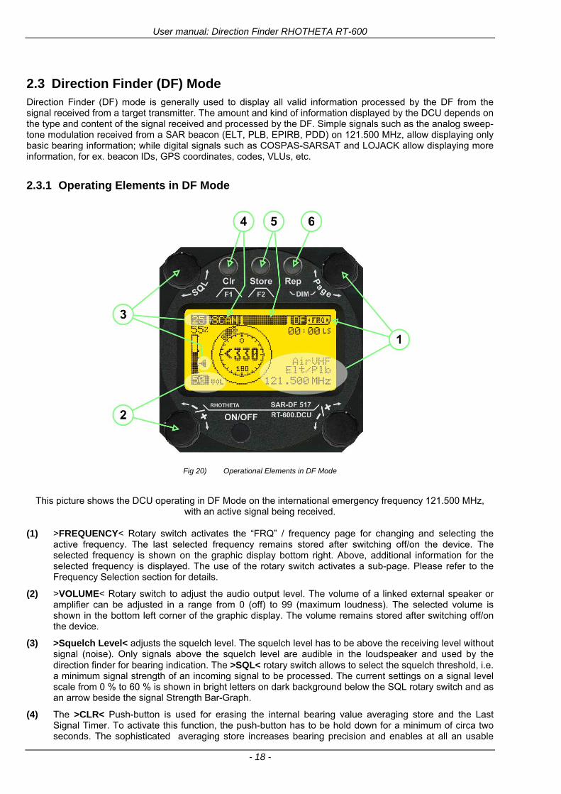
User manual Direction Finder RHOTHETA RT-600
- 18 -
23 Direction Finder (DF) Mode Direction Finder (DF) mode is generally used to display all valid information processed by the DF from the signal received from a target transmitter The amount and kind of information displayed by the DCU depends on the type and content of the signal received and processed by the DF Simple signals such as the analog sweep-tone modulation received from a SAR beacon (ELT PLB EPIRB PDD) on 121500 MHz allow displaying only basic bearing information while digital signals such as COSPAS-SARSAT and LOJACK allow displaying more information for ex beacon IDs GPS coordinates codes VLUs etc
231 Operating Elements in DF Mode
Fig 20) Operational Elements in DF Mode
This picture shows the DCU operating in DF Mode on the international emergency frequency 121500 MHz
with an active signal being received (1) gtFREQUENCYlt Rotary switch activates the ldquoFRQrdquo frequency page for changing and selecting the
active frequency The last selected frequency remains stored after switching offon the device The selected frequency is shown on the graphic display bottom right Above additional information for the selected frequency is displayed The use of the rotary switch activates a sub-page Please refer to the Frequency Selection section for details
(2) gtVOLUMElt Rotary switch to adjust the audio output level The volume of a linked external speaker or amplifier can be adjusted in a range from 0 (off) to 99 (maximum loudness) The selected volume is shown in the bottom left corner of the graphic display The volume remains stored after switching offon the device
(3) gtSquelch Levellt adjusts the squelch level The squelch level has to be above the receiving level without signal (noise) Only signals above the squelch level are audible in the loudspeaker and used by the direction finder for bearing indication The gtSQLlt rotary switch allows to select the squelch threshold ie a minimum signal strength of an incoming signal to be processed The current settings on a signal level scale from 0 to 60 is shown in bright letters on dark background below the SQL rotary switch and as an arrow beside the signal Strength Bar-Graph
(4) The gtCLRlt Push-button is used for erasing the internal bearing value averaging store and the Last Signal Timer To activate this function the push-button has to be hold down for a minimum of circa two seconds The sophisticated averaging store increases bearing precision and enables at all an usable
User manual Direction Finder RHOTHETA RT-600
- 19 -
bearing display in case of bad receiving signals (if there is a far away transmitter andor temporary complete loss of a receiving signal) Caused by the averaging procedure a drag error may occur which might be disturbing the bearing indication after a quick change of course of the aircraft or vehicle In this case the indicated bearing value lags by the real bearing value for about two seconds (for very weak signals even longer) By pressing this push-button after a quick change of course the display will show the new bearing value without drag error Additionally the F1CLR Push-Button is used to activate specific functions high-lighted in the menu below the button by pushing it for a short time (here as example ldquoSCANrdquo starts scanning the actual air band)
(5) gtSTORElt push-button Without function except if a special function is high-lighted in the menu line of the display
(6) gtREPEATlt Push-button when pressed and hold for min 3 sec the last valid bearing value with corresponding receiving level is displayed
232 Standard Display in DF Mode
Fig 21) DF Mode
(1) gtRelative Bearing valuelt by means of a sophisticated averaging procedure a steady display is
accomplished as graphic display and as text in the range of 0deghellip 359deg (0deg corresponds to bearing direct ahead)
(2) gtSpreadlt maximum deviation of un-averaged bearing values This is an indicator of bearing quality The wider the range between the directions of maximum deviation the worse the received signal is As a result of the excellent averaging procedure even with a spread of 45deg good bearing results are achieved
(3) gtReceiving levellt (field strength) of the signal as a relative percentage value visualized as bar-graph indication and as decimal value Even without a received signal a certain noise level may be displayed
(4) gtSquelch levellt (independently adjustable and stored for each frequency band) Squelch level is indicated as marker at the Signal Strength Bar-Graph or as direct relative level value A usable bearing analysis can only be achieved if the squelch level is above the noise level (without received signal) If the antenna unit is placed close a heavily disturbing electronic devices the squelch level has to be raised thus making the direction finder being less sensitive In receive modes where the squelch level is set automatically an ldquoArdquo above the marker indicates the ldquoAutosquelchrdquo functionality
(5) gtLast Signallt timer showing the time since a signal has been received for the last time (ie since a signal has been stronger than the squelch level) Values are ldquominutes secondsrdquo
User manual Direction Finder RHOTHETA RT-600
- 20 -
233 Special Options in COSPAS-SARSAT DF Mode
Especially for the use together with beacons transmitting a data signal according to COSPAS-SARSAT specifications in the 406-MHz-Band special functionalities and pages are being provided After selection of a COSPASSARSAT Frequency (Refer to the chapter ldquoFrequency selection Pagerdquo) the bearing page provides additional information and operating options
Fig 22) Operational Elements and Display in COSPAS-SARSAT DF Mode
(1) gtAuto Squelchlt indication indicating that the squelch level is set automatically to be close to the noise
floor It is recommended to always use the Auto Squelch during COSPAS-SARSAT operation This can be achieved by manually selecting 0 (lowest possible value) or 60 (highest possible value) as squelch level During COSPAS-SARSAT-Operation this will force the automatic setting of the level
(2) gt121500lt menu option The COSPAS-SARSAT signal in the 406 MHz band is transmitted only every 50 seconds in form of a short data burst of 440 or 520 ms approaching the transmitter it will be received earlier than the 121500 MHz continuous signal due to its high transmitter power However in a lower distance to a transmitter bearing on 121500 MHz is faster thanks to the continuous or rapidly intermittent signal The 121500 MHz menu option allows a direct switch-over to 121500 MHz Direct return back from 121500 to the COSPAS-SARSAT band is possible from the 121500 MHz bearing Window in COSPAS-SARSAT mode Please refer to the chapter ldquo121500 MHz bearing Window in COSPAS-SARSAT moderdquo for details
(3) gtDecodelt menu option allows to open the COSPASSARSAT Decode sub-page by shortly pushing the F2 push-button above the menu option
(4) gtFrequency rangelt indication COSPAS-SARSAT is using a channel spacing of 3 kHz for its beacons Due to the internal architecture of the direction finder it is possible to receive more than one channel in the same time Thus frequency steps of the direction finder are 833 kHz instead of 3 kHz The receive frequency covered by the current receive frequency setting is shown in the display line above the receive frequency indication
Important If the exact frequency of the COSPAS-SARSAT beacon is unknown it is strongly recommended to use the COSPAS-SARSAT scanning functionality in order to detect the correct frequency (Refer to the chapter ldquoFrequency selection Pagerdquo amp ldquoCOSPAS-SARSAT Scan Moderdquo)
User manual Direction Finder RHOTHETA RT-600
- 21 -
234 COSPAS-SARSAT Decode Window
The COSPAS-SARSAT Decode Window allows decoding incoming COSPAS-SARSAT data messages Only while this decode window is activated the decoding is possible An already received COSPAS-SARSAT puls while DF bearing mode was activated can not be used for decoding afterwards In this case the user has to wait while this decode window is active for the next transmitted puls approx 50 sec later
Fig 23) COSPAS-SARSAT Beacon Information Page
(1) gtExitlt push button (F1 button) allows to exit the decode window and switch back to the COSPAS-
SARSAT DF Mode page
(2) gtSARSATlt in the upper right corner of the display indicates that the COSPAS-SARSAT decode function is activated
(3) gtCountrylt displays the COSPAS-SARSAT Country Code coded into the received data message
(4) gtLast Signallt time since the last COSPAS-SARSAT message has been received in minutes secondsrsquo format
(5) gtPositionlt field showing in case of location protocols being used by the beacon the encoded GNSS position data (latitude longitude) transmitted by the beacon
(6) gt15-HEX-IDlt 15-HEX-ID of the beacon in hexadecimal format
(7) gtData stringlt of the bits 25 to 112 of the COSPAS-SARSAT data burst in case of short messages and bits 25 to 144 in case of a long message format The last 8 Hex Values are separated by a blank Bit- and Frame-synchronization hex values (Bits 1 to 24) are suppressed to increase the readability of the data message
(8) gtXlt sign to indicate that the Squelch is controlled by the antenna unit for optimum sensitivity The user has no access to the Squelch setting
User manual Direction Finder RHOTHETA RT-600
- 22 -
235 Tracking 121500 MHz while in COSPAS-SARSAT Mode
While in COSPAS-SARSAT DF Mode the user can switch to 121500 MHz in order to track the beacon in VHF If a valid signal is not received in 121500 MHz the user can switch back to the last active COSPAS-SARSAT channel (406 MHz frequency) being tracking previously
Fig 24) Tracking 121500 MHz while in COSPAS-SARSAT Mode
Differences are (1) gt406xlt press F1 to switch back to the last
COSPAS-SARSAT channel (406 MHz frequency) being tracking previously
(2) gt121500 MHzlt Actual frequency being tracked
User manual Direction Finder RHOTHETA RT-600
- 23 -
236 COSPAS-SARSAT Scan Mode
If the COSPAS-SARSAT Scan Mode has been selected at the frequency selection page ldquoFRQrdquo the COSPAS-SARSAT channels as selectable manually from the Frequency Selection Page are scanned After reception of a COSPAS-SARSAT Signal the scanning is stopped at the received frequency Due to the fast scanning ndash the complete COSPAS-SARSAT sub-band is scanned within less than 400 ms ndash detection of a receivable COSPAS-SARSAT signal is possible within one COSPAS-SARSAT repetition cycle
Fig 25) FRQ Selection Page with SCN COSPAS-SARSAT Scan Page selected
At the frequency selection page an active COSPAS SARSAT scanning can be stopped by de-activating it with the rotary button (1) While the scanning is active it is also possible by pressing gtF1lt ldquoEXITrdquo to switch back to the DF pagehellip
Fig 26) DF page with active COSPAS-SARSAT Scan Mode at the DF page
(1) gtSCANlt flashing indication notifying the user that the equipment is operating in scan mode
(2) Frequency display indicating the COSPAS-SARSAT scanning frequency range
(3) gtXlt sign showing that squelch settings are controlled autonomously by the receiver
Scan mode can be left by pressing gtF1lt ldquoSTOPrdquo
User manual Direction Finder RHOTHETA RT-600
- 24 -
237 Marine Ship Scan Mode
Fig 27) DF Mode FRQ = 156800 MHz F1 for scan function
If the active frequency (2) is within the VHF Marine Band a fast scan of all ship channels is possible by pushing gtF1lt ldquoSCAN (1) In this scanning mode all marine channels 1 to 88 (156025 to 157450 MHz) are scanned continuously until a signal is received To offer the best monitoring functionality for the user also signals between to channels (4) are detected (scanning without gap) In order to prevent the scan to stop on noisy frequencies it is recommended to start scanning with high squelch settings You can reduce the squelch level in steps until the scan stops on a noisy frequency for the first time Then increase the squelch level slightly This will result in the highest possible scan sensitivity and avoiding noisy channels due to RF disturbances sometimes generated by other equipment in own aircraft
Fig 28) DF Mode active scanning in process
The scanning is stopped by pressing gtF1lt ldquoSTOPrdquo (3)
User manual Direction Finder RHOTHETA RT-600
- 25 -
24 Law Enforcement Operation Law enforcement special ops and other organizations use the RT-600 LE (LAW ENFORCEMENT) version instead of the RT-600 A (STANDARD) version One of the reasons is that the LE version features scanning and tracking of signals like LoJack and ETS as well as signals in the 216000 MHz ndash 220000 MHz band such as medical beacons wristankle transmitters cashasset recovery ldquotagsrdquo etc However the LE version shares many functions in common with the A version such as scanning and tracking in the AIR band COSPAS-SARSAT band etc
241 Power-On procedure
The power-on procedure is the same as described in 211
(1) System Version ldquo(L)rdquo for LAW ENFORCEMENT version
Fig 29) STARTUP Screen (see 211 for details)
242 LoJack Scan Mode Start scanning for a VLU Code
For the convenience of Law Enforcement and other special ops users who frequently engage in tracking SVRS (Stolen Vehicle Recovery System) signals such as LoJack (LoJack Corp FCC 9020 Part 2 SVRS) RHOTHETA has optimized the power-on procedure of the RT-600 LE version so that right after the STARTUP screen the unit displays automatically the LoJack Scan Mode page to start immediately scanning for a valid VLU (Vehicle Location Unit) code without pressing any key
Fig 30) LoJack Scan Mode unit is scanning for a LoJack VLU Code
(1) gtscan LoJacklt DF is scanning for any new LoJack VLU Code
(2) gtEXITlt press F1 to exit and switch directly to DF Mode
User manual Direction Finder RHOTHETA RT-600
- 26 -
243 LoJack Scan Mode from any other page
While operating on any page other than the LoJack Scan page the user can switch directly to LoJack Scan Mode by pressing Hotkey F2 for 2 secs
(1) press Hotkey F2 for 2 secs to switch to the LoJack Scan page
Fig 31) Hotkey F2
User manual Direction Finder RHOTHETA RT-600
- 27 -
244 Manual activation of LoJack Scan Mode
(1) select the LoJack frequency (see also Frequency Selection Page)
(2) press F1 to switch back to the DF MODE
Fig 32) FRQ Selection Page FRQ = LoJack BAND = LoJack (164-174 MHz)
While in DF MODE with adjusted LoJack frequency the user can switch directly to the LoJack Scan by pressing gtF1lt ldquoSCANrdquo
(1) press F1 SCAN to switch to the LoJack Scan page
(2) still no LoJack ID filter used (ID=off) all transmissions are received on the active frequency as example also unwanted tower pulses
Fig 33) DF Mode with LoJack filter OFF
User manual Direction Finder RHOTHETA RT-600
- 28 -
245 Receiving and accepting a new VLU Code
While in LoJack Scan Mode waiting for a VLU Code if a new VLU Code is displayed the user can accept it and switch directly to DF Mode by pressing F2
(1) a new LoJack VLU Code (0001A) has been received
(2) press F2 to accept the new VLU Code (0001A) and switch to DF MODE page with the LoJack filter activated to track only 0001A
Fig 34) LoJack Scan Mode with new VLU Code received
246 Entering a new VLU Code manually
While in LoJack Scan Mode the user can enter a LoJack VLU code also manually
(1 2 3) use the SELECTplusmn and plusmnVALUE knobs to enter a new LoJack VLU Code active ID (0001A)
(4) Press F1 to accept the new VLU Code and switch to DF Mode with the LoJack filter ON to track only 0001A
Fig 35) LoJack Scan Mode with new VLU Code entered manually
User manual Direction Finder RHOTHETA RT-600
- 29 -
247 Tracking one VLU Code while monitoring new VLU Codes
While on DF Mode and tracking a VLU Code (0001A) the user can turn the LoJack switch OFF with F2 also the user can start scanning all VLUs again with F1
0001A is displayed as the active VLU Code filter function is ON only 0001A is tracked
Monitoring of other VLU Codes is active in the background
(1) Press F1 to switch to the LoJack Scan Mode to scan for new VLU Codes
(2) Press F2 to switch LoJack filter OFF
Fig 36) DF Mode with active VLU Code and LoJack filter ON
248 Tracking one VLU Code and receiving a new VLU Code
While on DF MODE page and tracking VLU Code (0001A) in the background a new VLU Code is received and decoded (G2HC7)
(1) The new VLU Code is announced (NEW G2HC7)
(2) Press F1 to switch to LoJack Scan Mode to see the arrival time of G2HC7 and the possibility to change bearing to this new G2HC7
Fig 37) DF Mode with active VLU Code and announcement of new VLU Code
User manual Direction Finder RHOTHETA RT-600
- 30 -
249 Switching to a new VLU Code
While on the LoJack Scan Page tracking one VLU Code (0001A) and notified of a new VLU Code (G2HC7)
(1) press F1 to continue tracking 0001A
(2) press F2 to start tracking G2HC7
(3) Time elapsed since G2HC7 was last received
(4) Time elapsed since 0001A was last received
If F1 is pressed for 2 sec the indicated VLU Code (G2HC7) and ID (0001A) are deleted
Fig 38) LoJack Scan Page with one active VLU Code and one new VLU Code
2410 ldquoBlockingrdquo function of one LoJack VLU Code
The LoJack scan page can also be used to ldquoblockrdquo one unwanted LoJack VLU ID signal by separating the adjusted active ID from any other received LoJack VLU signal This is done by muting the audio (see example below) when a LoJack signal with VLU code ldquo0001Ardquo is received gtgt Any new VLU Code (active LoJack signal) - except for 0001A ndash will be displayed on the top row and generate the audible beep tone
Fig 39) LoJack Scan Page with one active VLU Code and audio OFF
Tip ldquoBlockingrdquo is an important tool for practical missions As example a stolen vehicle with VLU ID ldquo0001Ardquo was tracked in the DF bearing mode The mission
is completed but the VLU is normally still transmitting With the settings above only new VLU signals except the now unwanted ldquo0001Ardquo are audible and displayed in the upper (scan LoJack hellip for new VLU) box
User manual Direction Finder RHOTHETA RT-600
- 31 -
2411 Tracking in the 216 to 220 MHz band
The RT-600 features scanning and bearing functionality in the 216000 MHz to 220000 MHz band The 216000 MHz ndash 220000 MHz band contains frequencies and signals used by special services and tracked by law enforcement special ops and similar organizations These are some of the frequencies and services in this band
CFR 90259 tx 216000 MHz to 220000 MHz
Low Power Radio Service (LPRS) tx 216000 MHz to 217000 MHz
Medical beacons Project Lifesaver tx wristankle tx 213000 MHz to 216000 MHz
ETS tx stolen cashasset recovery tx ldquobaitrdquordquotagrdquo tx 216000 MHz to 220000 MHz tx = transmitter(s) However any future or current user of the Rhotheta RT-600 must be aware that tracking signals on the frequencies listed above may be challenging and even frustrating due mostly to negative factors in some of the transmitters
bull Very low RF power output
bull Inefficient antennas
bull Battery-powered devices with a ldquolow batteryrdquo condition
bull Devices worn or located in conditions of poor RF propagation
bull Devices with channel spacing different than the one specified for the RT-600
These factors can make it very difficult for the DF to receive the signal andor display an accurate bearing Disclaimer For the reasons explained above and even though the RT-600 features top performance in its class RHOTHETA does not offer - and is not to be held responsible for - any guaranteed minimum range or distance to a transmitter in this band
25 Setup Edit Page System settings are displayed in the setup page The functions described in this section should be used by trained personal only
Fig 40) Accessing the Setup Page
The setup page can be accessed by holding down the gtCLRlt (1) and gtREPlt (2) buttons simultaneously and in the same time performing a left-hand turn on the gtPagelt rotary switch (3)
User manual Direction Finder RHOTHETA RT-600
- 32 -
Fig 41) Setup Page
(1) gtStorelt push-button must be pressed in parallel if a value of a setting shall be modified If a value can
be modified the background stops to blink
(2) gtSelectlt rotary switch used to scroll through the menu options The value of the actually activated menu option is high-lighted with dark background and blinking
(3) gtValuelt rotary switch used to change values in menu options (gtStorelt (1) has to be pressed in parallel if a value shall be modified)
(4) gtSN-Ratiolt menu option representing the necessary Signal-To-Noise-Ratio (Difference between signal and noise level) used as criterion for the automatic squelch function Please refer to the chapter ldquoSquelch Operationrdquo for details Default value is 60 dB
(5) gtMounting Positionlt menu option to select Top- or Bottom-Mounting of the DF antenna In case of rooftop installation (eg on land vehicles) ldquoToprdquo shall be selected In case of bottom-down (upside-down) installation (eg on a helicopter) ldquoBotrdquo shall be selected If this option is not selected correctly all bearing values will be mirror-inverted
(6) gtBearing Offsetlt menu option to include a constant offset correction to the bearing indication Bearing values in degrees will be changed according to the offset value
(7) gtMaximum External Dimming Voltage for Legendslt menu option which sets the upper limit of the dimming input voltage for the legends-panel Range=[15 hellip 28]V
(8) gtMinimum External Dimming Voltage for Legendslt menu option which sets the lower limit of the dimming input voltage for the legends-panel Range=[15 hellip 28]V
(9) gtPagelt rotary switch to be turned right-hand to go back to the Direction Finder page A left-hand turn on this rotary switch will show up an additional service page with debug information used for system checks
(10) gtExtended Seriallt It is possible to enable or disable the extended serial data protocol Only of interest if serial data is used by any connected control units like moving maps or computers For detailed information see (Serial interface data protocol (short description)gt at page 46) If there are compatibility problems with already existing older remote control software it is recommended to switch OFF the extended serial data protocol
User manual Direction Finder RHOTHETA RT-600
- 33 -
3 Error messages If an internal error of the device is recognized a corresponding flashing error message will be shown in the DF pages
Fig 42) Error Messages
(1) Error message including error code (in brackets)
(2) Short description of the indicated error
In case of coincidence of various errors the error with the highest priority will be displayed
Error message Error location Reason
Error (12) VOLTDU
Main voltage supply Main Voltage input too low ( 100 V)
Error (11) NO AU
Connection antenna display or Antenna Unit
No serial data (RS485) from Antenna Unit No or damaged connection between antenna and display or damaged antenna unit
Error (10) BAD AU
Connection antenna display
Incompatibility or bad data connection between display and antenna
Error (9) BAD RU
Remote Unit Incompatibility or bad data connection between display and external serial Remote Unit or PC
Error (8) VOLTAU
Antenna Unit Voltage supply at Antenna Unit too low ( 90 V) Main voltage supply too low or considerable drop of voltage between display and antenna
Error (7) BAD DCU
Connection Display Antenna
Incompatibility or bad data connection between antenna and display
Error (6) NO DCU
Connection Display Antenna
No serial data from Display Control Unit to Antenna Unit
Error (5) PLL ERR
antenna Error in synthesizer-oscillator of receiver in Antenna Unit
Error (4) FRQ+OFS
received transmitter Received frequency too high (more than 6 KHz error of transmitter)
Error (3) FRQ-OFS
received transmitter received frequency too low (more than 6 KHZ error of transmitter)
Error (2) DECODE
radio distance transmitter DF
Data Bits of decoded signal (COSPAS-SARSAT or LoJack) defective
Error (1) DATARNG
Incompatibility of data DCU AU
Protocol data bytes out of valid range
Error (0) NO REC
Antenna Unit receiver
Receiver board defective
User manual Direction Finder RHOTHETA RT-600
- 34 -
4 Installation
41 Antenna unit A convenient position of the monopole bearing antenna is crucial for good bearing results The antenna needs an effective ground connection to the body of the aircraft or to the roof of the vehicle If there is no metallic mounting surface available a metallic sheet or similar (net) with connection to ground has to be applied first between vehicle-body and antenna In this hatched area the antenna touches the body ofthe vehicleaircraft In order to obtain a good groundconnection the surface of the body should be bared(Measuring unit [mm])
8 x holes for mounting the antenna unit to the
vehicle aircraft
Fig 43) Antenna Mounting Drawing
User manual Direction Finder RHOTHETA RT-600
- 35 -
411 Influence of antenna location and environment on the bearing accuracy
Recommendations concerning the practical antenna unit location on helicopters and airplanes
The bearing accuracy of the direction finder antenna unit is severely influenced (comparable to an airspeed sensor) by the environment For comparison a perfect high quality speed sensor will not indicate the true airspeed if this sensor is interfered by strong turbulences The direction finder antenna unit acts as a sensor for electromagnetic waves In the near field of this antenna unit any conductive (eg metallic) obstacle will influence the incoming wave field and create reflections which decrease the bearing accuracy These are general physical limitations concerning all types of direction finder systems To achieve the best bearing results it should be considered that the antenna unit is installed as far away as possible from any other vertically polarized conductive structure If possible there should be no reflectors within an area of 2-3 feet around the antenna unit In this worst case example the direction finder will not work properly
Fig 44) Antenna Installed in a Bad Location
In this example the antenna unit is located too close to the cable cutter of the helicopter This cutter will produce strong reflections especially as the length is equal to Lambda4 within the VHF airband
User manual Direction Finder RHOTHETA RT-600
- 36 -
Examples of properly installed direction finder antenna units
Fig 45) Antenna Installed in Good Locations
User manual Direction Finder RHOTHETA RT-600
- 37 -
42 Display and Control Unit
The display control unit may be mounted into a front panel by the means of this mounting drawing
Fig 46) DCU Mounting Drawing
(all dimensions in [mm]) To install or uninstall the display control unit perform the following steps (1) Remove the cover caps of the four rotary switches
(2) Loose the screws visible below the position of the cover caps
(3) Remove the plastic button from the axis of the four rotary switches
(4) Mount dismount the display control unit
(5) Re-install the plastic buttons on the axis of the four rotary switches
(6) Fix the screws so that the plastic buttons are fixed on the axis
(7) Re-install the cover caps on the four rotary switches
User manual Direction Finder RHOTHETA RT-600
- 38 -
43 System Interconnect Wiring Diagram (Also refer to chapter ldquoTechnical Datardquo for details)
Fig 47) System Interconnect Wiring Diagram
6-pol Amphenol plug femalePTG06SE10-6S(SQ)
max length of cable 20 m 9-pol Sub-D plug (femalemale)
User manual Direction Finder RHOTHETA RT-600
- 39 -
5 Technical Data
51 Electric features
Method of bearing Doppler-principle (3 kHz rotational frequency right left rotation)
Bearing accuracy1 plusmn 5deg RMS
Internal resolution 1deg
Bearing Sensitivity VHF AirEmergency le 25 μVm (typical)
VHF Marine le 25 μVm (typical)
UHF Emergency and ETS le 4 μVm (typical)
COSPAS-SARSAT le 4 μVm (typical)
LoJack Decoding (50 Message Error Rate) and bearing le 5 μVm (typical)
Frequency stability plusmn 20 ppm (Δff = plusmn210-6)
Reception frequencies
SAR version (Standard)
Frequency Options
VHF Emergency Band 118000 to 124000 MHz (833 kHz steps AM)
VHF Marine Band 154000 to 163000 MHz ( 500 kHz steps FM) (channel 16 selectable via channel no)
UHF Emergency Band 240000 to 246000 MHz (2500 kHz steps AM)
UHF FM Band 406100 to 410000 MHz ( 500 kHz steps FM)
COSPAS-SARSAT 400000 to 406092 MHz Including 406022 to 406076 MHz (Channel A S)
F1 VHF Air Band 118000 to 136992 MHz
F2 extended VHF Marine Band 137000 to 224995 MHz
F3 extended UHF Air Band 225000 to 399975 MHz
F4 additional UHF FM Band 406100 to 470000 MHz
Reception frequencies
LAW Enforcement version
Frequency Options
VHF Emergency Band 118000 to 124000 MHz (833 kHz steps AM)
VHF Marine Band 154000 to 163000 MHz (500 kHz steps FM) (channel 16 selectable via channel no)
LoJack 164000 to 174000 MHz (125 kHz steps FM)
ETS 216000 to 220000 MHz (10125 kHz AM)
COSPAS-SARSAT 400000 to 406092 MHz Including 406022 to 406076 MHz (Channel A S)
F1VHF Air Band 118000 to 136992 MHz
F2 extended VHF Marine Band 137000 to 163000 MHz
COSPAS-SARSAT fast scan mode
Full automatic detection of any active COSPAS-SARSAT channel A to S within 400 ms
COSPAS-SARSAT decoding
Reception and decoding of COSPAS-SARSAT data signal (112 or 144 bit) specified according to COSPAS-SARSAT
LoJack decoding Selectable LoJack ID display and selective active filtering
Special scanning modes
complete maritime ship band scanning within 3 s (channel 01 hellip 88 also frequencies between 2 channels are included)
1With undisturbed wave field and sufficient field strength Measuring by changing the angle of incidence with the antenna rotating on a revolving table in order to eliminate environmental influences on the results No modulation
User manual Direction Finder RHOTHETA RT-600
- 40 -
Bearable modulation A3E F3E A3X (ELT-modulation) F1D G2D COSPAS-SARSAT Bearing largely independent of modulation
Polarization Vertical
Polarization error 5deg at 60deg field vector rotation
Garbling cone Ca 30deg to the vertical
Time of response2 50 ms (with sufficient reception field strength)
LC-graphic display 128 x 64 pixels supertwist transflective extended range of temperature dark-blue display on yellow-green background background light Freely adjustable (exponential) dimming of brightness
NVG cockpit design Fully compatible NVIS Green B display Control Unit optional
Operating voltage 275 V nominal 12 V to 35 V DC
Current consumption LCD-background light Off max 500 mA (12 V DC) max 250 mA (24 V DC)
LCD-background light 100 max 750 mA (12 V DC) max 350 mA (24 V DC)
LCD-background light 100 max 900 mA (12 V DC) with NVG Option max 400 mA (24 V DC)
Audio out For external speaker approx 2 W (4 Ω)
Serial data interface Serial interface RS-232 (9600 baud 8 data bits 1 stop bit no parity)
2Very weak signals can considerably increase the time of response
User manual Direction Finder RHOTHETA RT-600
- 41 -
52 Interface External connections (optional at Sub-D 9-pol Male connector)
Dimming
Pin 8
external voltage input for variable dimming of legends
(optional)
Analog input signal for variable control of the legends illumination Input voltage range is freely adjustable in the range of 15 hellip 28 V in the setup menu Refer to chapter ldquoSetup Pagerdquo Default setting 8 hellip28 V (8 V = Off 28 V = max dimming for legends)
Input Impedance gt 50 k
Pin 6 night status line for LCD
dimming (optional)
Low-active (as example switch to ground) At input voltage lt 25 VDC the LCD dimming operates in nightNVG mode Maximum brightness ca 4 of daydefault mode brightness
Input Impedance gt 50 k
Pin 4 NVG status line for LCD
dimming (optional)
Low-active (as example switch to ground) At input voltage lt 25 VDC the LCD dimming operates in nightNVG mode Maximum brightness ca 4 of daydefault mode brightness
Input Impedance gt 50 k
AudioLF
Pin 7 Audio output signal
AC coupled voltage source with very low inner resistance Maximum output voltage ca 8 VPP = 283V RMS at maximum Volume Maximum output power ca 2 W with 4 speaker
If a headphone is connected ([32hellip600] 100mW) we recommend using a resistor (18 025 W) between audio output and headphone to prevent damage of the headphone
Serial interface RS232 (9600 baud 8 data bits 1 stop bit no parity)
Pin 3 TXD Serial output (ca plusmn10 V)
Pin 2 RXD Serial input (ca plusmn10 V)
User manual Direction Finder RHOTHETA RT-600
- 42 -
53 Mechanical features
Temperature range
Display Control Unit permissible operating temperature3 -20 degC +60 degC permissible storage temperature -30 degC +80 degC
Antenna Unit permissible operating temperature3 -40 degC +60 degC permissible storage temperature -55 degC +80 degC
Protective system Antenna Unit IP 67
Weights Display Control Unit 250 g Antenna Unit 2000 g
Dimensions Display Control Unit 82 mm x 82 mm x 43 mm (width x height x depth) Antenna Unit 270 mm x 185 mm
Fig 48) DCU Mechanical Drawing (all dimensions in [mm])
3 For temperatures lower than ndash10deg C a warm-up period of 15 min should be allowed
User manual Direction Finder RHOTHETA RT-600
- 43 -
Fig 49) AU Mechanical Drawing (all dimensions in [mm])
User manual Direction Finder RHOTHETA RT-600
- 44 -
6 Appendix
61 Frequency Ranges
User manual Direction Finder RHOTHETA RT-600
- 45 -
62 Frequencies of channels on maritime band (only for standard [A] version) Frequency-range of the RT-600 in the maritime band 156000 MHz 162025 MHz
Channel No frequency (ship - station) Frequency (coast - station)
1 156050 MHz 160650 MHz 2 156100 MHz 160700 MHz 3 156150 MHz 160750 MHz 4 156200 MHz 160800 MHz 5 156250 MHz 160850 MHz 6 156300 MHz 160900 MHz 7 156350 MHz 160950 MHz 8 156400 MHz 9 156450 MHz
10 156500 MHz 11 156550 MHz 12 156600 MHz 13 156650 MHz 14 156700 MHz 15 156750 MHz 16 156800 MHz 17 156850 MHz 18 156900 MHz 161500 MHz 19 156950 MHz 161550 MHz 20 157000 MHz 161600 MHz 21 157050 MHz 161650 MHz 22 157100 MHz 161700 MHz 23 157150 MHz 161750 MHz 24 157200 MHz 161800 MHz 25 157250 MHz 161850 MHz 26 157300 MHz 161900 MHz 27 157350 MHz 161950 MHz 28 157400 MHz 162000 MHz 60 156025 MHz 160625 MHz 61 156075 MHz 160675 MHz 62 156125 MHz 160725 MHz 63 156175 MHz 160775 MHz 64 156225 MHz 160825 MHz 65 156275 MHz 160875 MHz 66 156325 MHz 160925 MHz 67 156375 MHz 68 156425 MHz 69 156475 MHz 70 156525 MHz 71 156575 MHz 72 156625 MHz 73 156675 MHz 74 156725 MHz 75 156775 MHz 76 156825 MHz 77 156875 MHz 78 156925 MHz 161525 MHz 79 156975 MHz 161575 MHz 80 157025 MHz 161625 MHz 81 157075 MHz 161675 MHz 82 157125 MHz 161725 MHz 83 157175 MHz 161775 MHz 84 157225 MHz 161825 MHz 85 157275 MHz 161875 MHz 86 157325 MHz 161925 MHz 87 157375 MHz 161975 MHz 88 157425 MHz 162025 MHz
User manual Direction Finder RHOTHETA RT-600
- 46 -
63 Serial interface data protocol (short description)
631 General
Interface parameters RS232 9600 Baud 8 databits 1 stopbit no parity LSB sent first Timing of serial data For accurate use of the serial data (even for the optional serial input commands) the correct timing is mandatory The DCU (Display Control Unit) sends out via the RS-232 Pins (see 43 System Interconnect Wiring Diagram page 38) cyclic and autonomous every approx 250300 ms a binary data stream which contains all relevant DF-bearing information The output data contains one or two blocks of binary data (see next picture with accordingly description) The optional serial input is only used if changes (as example frequency change) are done by additional remote control units
Fig 50) Timing of serial data
Serial standard output
This output data is always available and contains all relevant DF-bearing data For detailed content see page 47
Optional extended serial output
This data contains some additional information like as example CospasSarsat or LoJack decoding and ID data For detailed content see page 50 The data is only available with DCU Software [Rev ge 320] and if this optional data block is configured as ON = enabled (see Setup Edit Page point (10) )
Even to avoid compatibility problems with already existing older remote control software it is possible to disable switch off this additional data block (see Setup Edit Page point (10) )
Optional serial input
Only used for optional commands to control DCU parameters If as example the direction finder frequency is changed remotely there is send to the DCU one time this data block with the new frequency For detailed content see page 52
User manual Direction Finder RHOTHETA RT-600
- 47 -
632 Serial standard output (protocol description)
Specification serial standard output
The binary data stream with a length of 39 bytes starts with a header byte (value = hex 0xA0 as ID for DF Mode) The next bytes contain different values for status bearing information and also service The last byte is used for data stream checksum control Remark This is a binary data protocol So every byte value from 0dec hellip 255dec (0x00 hellip 0xFF) is possible Because of this it is not allowed to realize a start byte detection by the content (0xA0) The idle line detection is recommended for detection the end of message Register of databytes (for details see next page)
byte no
[0] Header = 0xA0 Id for DF Mode
[1] Number = 39 = bytes in the complete message (including header and checksumbyte)
[2] Status (1) HSB [x|x|x|x|x|x|x|x] LSB | | | | | | | --gt (0) Receiving | | | | | | ----gt (1) Squelch controlled by AU (X) | | | | | ------gt (2) Permission RL Calibration | | | | --------gt (3) Line Night | | | ----------gt (4) Line NVG | | ------------gt (5) Dimming External | --------------gt (6) Autosquelch Active ----------------gt (7) 0=Standard Version 1=LE Version
[3] Status (2) HSB [x|x|x|x|x|x|x|x] LSB | ----------------gt (7) 0=Standard 1=extended serial dataprotocol = ONactive
[45] Error (Bits[120])
[6] Actual DCU Page
[7] Volume [0hellip100]
[811] Frequency [Hz]
[12] Active Band
[13] Actual Squelchlevel [0hellip60]
[14] Audio-Line amp_NF_Test Output
[15] (Not used)
[1617] Voltage_DCU ([0hellip335]=[0 hellip 335]V
[1819] Voltage_AU ([0hellip255]=[0 hellip 255]V
[20] Temperature_AU [-68hellip+127]degC
[21] Frequency Offset [-99hellip+99]
[2225] ServiceTest values (mode dependent test values for service only)
26 (Not used reserved)
[27] Level [0hellip100]
[2829] Bearing Averaged [0hellip359]deg relative
[3031] Bearing Live_Min [0hellip359]deg relative
[3233] Bearing Live_Max [0hellip359]deg relative
[34] Test Value PS-RAM Right Rotation[0hellip178] (for service only)
[35] Test Value PS-RAM Left Rotation [0hellip178] (for service only)
[3637] (Not used reserved)
[38] Checksum is the 2rsquos complement of the modulo-256 sum of all bytes without checksum-byte [0n-1]
User manual Direction Finder RHOTHETA RT-600
- 48 -
Detailed Description of important values for practical use
Status byte [2] Receiving Bit 0 of this value (LSB) indicates signal receiving Bit 0 = 0 then no signal is received and so on no bearing is available Bit 0 = 1 then bearing is possible Bit 1 if(1) then Squelch is controlled by AU (active at modes CospasSarsat Decode CospasSarsat Scanning LoJack with Filter=ID only)
Error bytes [4hellip5] 16 bit value each set bit corresponds to the error no (Refer to the chapter Error messages) Example - 0x0000 No error - 0x0800 Bit No 11 Set ( = No AU Error)
Actual DCU Page byte [6] indicates actual operating mode of DCU 0 = Standard bearing page 1 = Frequency memory page 2 = CospasSarsat decoding page 3 = LoJack decoding page (ID edit)
Frequency bytes [8hellip11] 32 bit value actual adjusted frequency [Hz] Example - 0x073DF160 1215000000 121500 MHz
Active Band Standard Version [A] 0=VHF Airband 1=VHF Marineband sea 2=VHF Marineband coast 3=UHV Airband 4=CospasSarsat LE Version [L] 0=VHF Airband 1=LoJack 2=Lifesaver 3=ETS 4=CospasSarsat
Actual Squelchlevel byte [13] Range [0hellip60] without signal the actual squelchlevel should always be adjusted a little bit over the noise level (Refer to the chapter Squelch operation)
Level byte [27] Range [099] actual receiving level (without signal this value is equal to the noise level) If a signal is received then this value corresponds to the signal strength of this signal
Relative Bearing averaged byte [2829] 16 bit value Range [0hellip359 0xFFFF] if the value = 0xFFFF then no valid bearing is available otherwise this value contains the actual averaged bearing information in Deg [0deg359deg] Example - 0X0114 276deg bearing (= left side oriented to heading)
Bearing Live MinMax byte[3031] amp [3233] - 16 bit values Range [0hellip359 0xFFFF] Only for signal quality or additional information ndash NOT recommended for bearing indication The relative live bearing field contains the maxmin bearing in degrees without averaging The relative live bearing reacts faster than the normal relative bearing but it has not the precision of the averaged bearing The MinMax Bearing Values are calculated within a time period of approx 250 ms If they are very close together (for example ldquo124rdquo and ldquo128rdquo degrees) then the signal quality is quite good A wide span of the minmax values (for example ldquo97rdquo and ldquo162rdquo) shows very noisy but nevertheless bearable signal quality
User manual Direction Finder RHOTHETA RT-600
- 49 -
633 DCU Info output (protocol description)
Specification DCU Info output
Remark This protocol is only available while the SetupEdit page is activated at the DCU
byte no
[0] Header = 0xAF Id for DCU Info Mode
[1] Number = 39 = bytes in the complete message (including header and checksumbyte)
[2]
(see standard output) [3]
[45]
[621] Info String of 15 byteschars the string contains Information about Unit Variant Software Version and Serial No
Example Byte [318] =
|--AU ID---||Var-||---Software Version---| |-------------- Serial No---------------| [0x44][0x55][0x41][0x33][0x2E][0x33][0x30][0x3A][0x20][0x20][0x30][0x31][0x32][0x33][0x34][0x00] rsquoDrsquo rsquoUrsquo rsquoArsquo rsquo3rsquo rsquorsquo rsquo3rsquo rsquo0rsquo rsquorsquo rsquo rsquo rsquo rsquo rsquo0rsquo rsquo1rsquo rsquo2rsquo rsquo3rsquo rsquo4rsquo rsquoENDrsquo | | | | __________________ | | ________________________ | n n n | | n n n n n | (Software Version) | | (Serial No) | gt rsquoArsquo = Standard Variant gt rsquoLrsquo = Law Enforcement Variant
User manual Direction Finder RHOTHETA RT-600
- 50 -
634 Optional extended serial output (protocol description)
The data content depends on the actual mode of the direction finder To get special data the direction finder has first to be switched to the equivalent mode
COSPAS-SARSAT Decoding data
This data is only available and valid if Display Control Unit with actual software Rev ge 320 (see Power-On procedure page 10) Configuration of Extended serial = ON (see Setup Edit Page point (10) ) Direction Finder COSPAS-SARSAT decoding mode is activated by selecting the corresponding page
(see COSPAS-SARSAT Decode Window page 20 and page 21) and so on Header (byte 0 of data) = 0x91
A valid COSPAS-SARSAT decoding data protocol is always marked by the first data byte (header = 0x91) Always after receiving and decoding of a valid COSPAS-SARSAT pulse the complete data protocol with 33 bytes is send out one time
Byte No
[0] Header = 0x91 (Identification for CPSarsat decoding mode)
[1] Number of bytes - 7 if no decoded pulse is available - 33 if new pulse was received and is available
[2] Error
[3] Bit[0] - 0 =gt No new 406 MSG (decoded data) available - 1 =gt New valid 406 MSG available (Sync amp Frame Ok) Check Error Status for Bit-Errors
Bit[61] AutoSquelch Level valid range [060] ( decimal)
Bit[7] = 1 Squelch controlled by AU
[4] Signallevel of received signal valid range [099] ( decimal)
[5] Voltage of Antenna Unit Power Supply input valid range [80255] (decimal = 80 255 V DC)
[6] Temperature inside Antenna Unit valid range [-50+100] (degC signed byte value)
The following databytes are only available if a correct CPSarsat puls gets received and decoded with correct checksum
[724] 18 x Databytes complete orginal CPSarsat 406 decoded message (144 bit)
Databyte Nr [ Byte 7 ] [ Byte 8 ] [Byte9 Byte24] 406 MSG Bit Nr [1 2 3 4 5 6 7 8] [9 10 11 12 13 14 15 16] [17 144]
[25] SN-Flag valid values 0x53=rsquoSrsquo 0x4E=rsquoNrsquo 0x2D=rsquo-rsquo if no GPS data available
GPS-Position Latitude
[26] Deg valid values [090] (decimal Deg) 0xFF if no GPS data available
[27] Min valid values [059] (decimal Deg) 0xFF if no GPS data available
[28] Sec valid values [059] (decimal Deg) 0xFF if no GPS data available
[29] WE-Flag valid values 0x57=rsquoWrsquo 0x45=rsquoErsquo 0x2D=rsquo-rsquo if no GPS data available
GPS-Position Longitude
[30] Deg valid values [0180] (decimal Deg) 0xFF if no GPS data available
[31] Min valid values [059] (decimal Deg) 0xFF if no GPS data available
[32] Sec valid values [059] (decimal Deg) 0xFF if no GPS data available
User manual Direction Finder RHOTHETA RT-600
- 51 -
LoJack ID data
This data is only available and valid if Display Control Unit with actual software Rev ge 320 (see Power-On procedure page 10) Direction Finder of variant [L] Law Enforcement Configuration of Extended serial = ON (see Setup Edit Page point (10) ) Direction Finder is working with active LoJack gtID Filterlt Header (byte 0 of data) = 0x93 or 0x94
Valid LoJack ID decoding data is always marked by the first data byte (header = 0x93 or 0x94)
Byte No
[0] Header = 0x93 LoJack ID editing sub-page is selected Filter = VLU all valid and received LoJack pulses are indicated = 0x94 Lojack Decode amp DF Mode with active Filter = ID
[1] Number of bytes in the complete data stream - decimal 26 = default value
[2] Nonrelevant
[3] Bit[0] Receiving OnOff - 0 =gt No Receiving no bearing - 1 =gt new LoJack pulse received
[412] Nonrelevant
[1317] Lojack ID
Replay Code 5 x ASCII Chars ldquoNo BIOZrdquo set
Example ASCII = ldquo000R1rdquo
18 Receiver Level Out Max [099]
19
LoJack Decoder Status [07] - 0 Off - 1 Wait for Preamble - 2 Preamble Ok - 3 FlagPattern Ok - 4 Data BitError gt 1 - 5 Data Ok (No VLU) - 6 VLU Ok - 7 ID Ok (Filter=IDONLY)
[2025] Nonrelevant
Remark Only if byte no [3] bit [0] gets ldquo1rdquo (Receiving On) then an active LoJack pulse is received and so on the corresponding LoJack ID valid otherwise the LoJack ID only shows the actual adjusted LoJack Filter ID of the direction finder
User manual Direction Finder RHOTHETA RT-600
- 52 -
635 Optional serial input (protocol description)
Specification serial input (optional)
The serial input is normally used for service and maintenance only Nevertheless it is possible via this interface to remote control the actual frequency and the squelchlevel of the DF system If a valid data stream is send to the DF then the actual frequency selection at the DCU is switched to Block2 AUX0 At this memory channel the new frequency is stored and used automatically (Refer to the chapter Frequency Selection Page) If the frequency is changed (by one valid data stream) no more serial input is necessary The actual frequency can be changed again at any time by manual operation at the DCU The timing of serial input (if used) is strictly fixed The optional serial input has to take place directly after a complete serial output (max 50 ms delay time) If a new changed frequency is commanded to the DCU via this serial input interface it can take up to 1 sec of time until this new frequency is ready for operationbearing It is strictly not recommended to use the frequency remote control for any scan mode The frequency control has to be used for static frequency change only Register of databytes
byte no
[0] Header 0xC0
[1] Number of bytes in the complete message (including header and checksumbyte)
[23] (not used for normal operation any byte values allowed)
[4] Volume [0100]
[58] Frequency [Hz] (frequency is rounded to the according grid automatically)
Valid Range for Standard Version Valid Range for LE Version
118000000 hellip 123000000 [Hz] 8333 kHz 118000000 hellip 123000000 [Hz] 8333 kHz
156050000 hellip 162025000 [Hz] 5000 kHz 164000000 hellip 174000000 [Hz] 8333 kHz
201000000 hellip 215995000 [Hz] 5000 kHz
240000000 hellip 246000000 [Hz] 8333 kHz 216000000 hellip 218995000 [Hz] 12500 kHz219000000 hellip 220000000 [Hz] 10000 kHz
400000000 hellip 410000000 [Hz] 8333 kHz 400000000 hellip 410000000 [Hz] 8333 kHz
[9] Squelchlevel Manual = [0hellip60] Autosql= [ -1] Warning use only for pulsed signals (as example CpSarsat LoJack)
[10] (not used for normal operation any byte values allowed)
[11] Internal Dimming [0100]
[12] Checksum is the 2rsquos complement of the modulo-256 sum of all bytes without checksum-byte [0n-1]
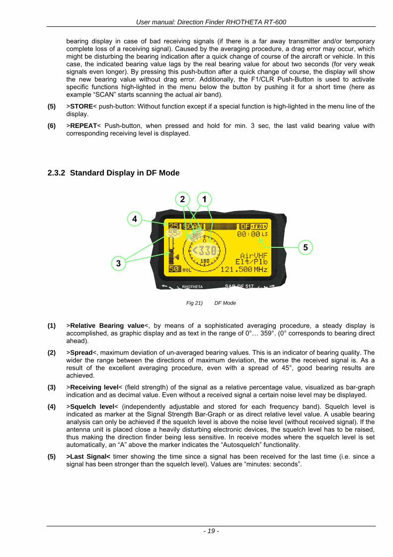
User manual Direction Finder RHOTHETA RT-600
- 19 -
bearing display in case of bad receiving signals (if there is a far away transmitter andor temporary complete loss of a receiving signal) Caused by the averaging procedure a drag error may occur which might be disturbing the bearing indication after a quick change of course of the aircraft or vehicle In this case the indicated bearing value lags by the real bearing value for about two seconds (for very weak signals even longer) By pressing this push-button after a quick change of course the display will show the new bearing value without drag error Additionally the F1CLR Push-Button is used to activate specific functions high-lighted in the menu below the button by pushing it for a short time (here as example ldquoSCANrdquo starts scanning the actual air band)
(5) gtSTORElt push-button Without function except if a special function is high-lighted in the menu line of the display
(6) gtREPEATlt Push-button when pressed and hold for min 3 sec the last valid bearing value with corresponding receiving level is displayed
232 Standard Display in DF Mode
Fig 21) DF Mode
(1) gtRelative Bearing valuelt by means of a sophisticated averaging procedure a steady display is
accomplished as graphic display and as text in the range of 0deghellip 359deg (0deg corresponds to bearing direct ahead)
(2) gtSpreadlt maximum deviation of un-averaged bearing values This is an indicator of bearing quality The wider the range between the directions of maximum deviation the worse the received signal is As a result of the excellent averaging procedure even with a spread of 45deg good bearing results are achieved
(3) gtReceiving levellt (field strength) of the signal as a relative percentage value visualized as bar-graph indication and as decimal value Even without a received signal a certain noise level may be displayed
(4) gtSquelch levellt (independently adjustable and stored for each frequency band) Squelch level is indicated as marker at the Signal Strength Bar-Graph or as direct relative level value A usable bearing analysis can only be achieved if the squelch level is above the noise level (without received signal) If the antenna unit is placed close a heavily disturbing electronic devices the squelch level has to be raised thus making the direction finder being less sensitive In receive modes where the squelch level is set automatically an ldquoArdquo above the marker indicates the ldquoAutosquelchrdquo functionality
(5) gtLast Signallt timer showing the time since a signal has been received for the last time (ie since a signal has been stronger than the squelch level) Values are ldquominutes secondsrdquo
User manual Direction Finder RHOTHETA RT-600
- 20 -
233 Special Options in COSPAS-SARSAT DF Mode
Especially for the use together with beacons transmitting a data signal according to COSPAS-SARSAT specifications in the 406-MHz-Band special functionalities and pages are being provided After selection of a COSPASSARSAT Frequency (Refer to the chapter ldquoFrequency selection Pagerdquo) the bearing page provides additional information and operating options
Fig 22) Operational Elements and Display in COSPAS-SARSAT DF Mode
(1) gtAuto Squelchlt indication indicating that the squelch level is set automatically to be close to the noise
floor It is recommended to always use the Auto Squelch during COSPAS-SARSAT operation This can be achieved by manually selecting 0 (lowest possible value) or 60 (highest possible value) as squelch level During COSPAS-SARSAT-Operation this will force the automatic setting of the level
(2) gt121500lt menu option The COSPAS-SARSAT signal in the 406 MHz band is transmitted only every 50 seconds in form of a short data burst of 440 or 520 ms approaching the transmitter it will be received earlier than the 121500 MHz continuous signal due to its high transmitter power However in a lower distance to a transmitter bearing on 121500 MHz is faster thanks to the continuous or rapidly intermittent signal The 121500 MHz menu option allows a direct switch-over to 121500 MHz Direct return back from 121500 to the COSPAS-SARSAT band is possible from the 121500 MHz bearing Window in COSPAS-SARSAT mode Please refer to the chapter ldquo121500 MHz bearing Window in COSPAS-SARSAT moderdquo for details
(3) gtDecodelt menu option allows to open the COSPASSARSAT Decode sub-page by shortly pushing the F2 push-button above the menu option
(4) gtFrequency rangelt indication COSPAS-SARSAT is using a channel spacing of 3 kHz for its beacons Due to the internal architecture of the direction finder it is possible to receive more than one channel in the same time Thus frequency steps of the direction finder are 833 kHz instead of 3 kHz The receive frequency covered by the current receive frequency setting is shown in the display line above the receive frequency indication
Important If the exact frequency of the COSPAS-SARSAT beacon is unknown it is strongly recommended to use the COSPAS-SARSAT scanning functionality in order to detect the correct frequency (Refer to the chapter ldquoFrequency selection Pagerdquo amp ldquoCOSPAS-SARSAT Scan Moderdquo)
User manual Direction Finder RHOTHETA RT-600
- 21 -
234 COSPAS-SARSAT Decode Window
The COSPAS-SARSAT Decode Window allows decoding incoming COSPAS-SARSAT data messages Only while this decode window is activated the decoding is possible An already received COSPAS-SARSAT puls while DF bearing mode was activated can not be used for decoding afterwards In this case the user has to wait while this decode window is active for the next transmitted puls approx 50 sec later
Fig 23) COSPAS-SARSAT Beacon Information Page
(1) gtExitlt push button (F1 button) allows to exit the decode window and switch back to the COSPAS-
SARSAT DF Mode page
(2) gtSARSATlt in the upper right corner of the display indicates that the COSPAS-SARSAT decode function is activated
(3) gtCountrylt displays the COSPAS-SARSAT Country Code coded into the received data message
(4) gtLast Signallt time since the last COSPAS-SARSAT message has been received in minutes secondsrsquo format
(5) gtPositionlt field showing in case of location protocols being used by the beacon the encoded GNSS position data (latitude longitude) transmitted by the beacon
(6) gt15-HEX-IDlt 15-HEX-ID of the beacon in hexadecimal format
(7) gtData stringlt of the bits 25 to 112 of the COSPAS-SARSAT data burst in case of short messages and bits 25 to 144 in case of a long message format The last 8 Hex Values are separated by a blank Bit- and Frame-synchronization hex values (Bits 1 to 24) are suppressed to increase the readability of the data message
(8) gtXlt sign to indicate that the Squelch is controlled by the antenna unit for optimum sensitivity The user has no access to the Squelch setting
User manual Direction Finder RHOTHETA RT-600
- 22 -
235 Tracking 121500 MHz while in COSPAS-SARSAT Mode
While in COSPAS-SARSAT DF Mode the user can switch to 121500 MHz in order to track the beacon in VHF If a valid signal is not received in 121500 MHz the user can switch back to the last active COSPAS-SARSAT channel (406 MHz frequency) being tracking previously
Fig 24) Tracking 121500 MHz while in COSPAS-SARSAT Mode
Differences are (1) gt406xlt press F1 to switch back to the last
COSPAS-SARSAT channel (406 MHz frequency) being tracking previously
(2) gt121500 MHzlt Actual frequency being tracked
User manual Direction Finder RHOTHETA RT-600
- 23 -
236 COSPAS-SARSAT Scan Mode
If the COSPAS-SARSAT Scan Mode has been selected at the frequency selection page ldquoFRQrdquo the COSPAS-SARSAT channels as selectable manually from the Frequency Selection Page are scanned After reception of a COSPAS-SARSAT Signal the scanning is stopped at the received frequency Due to the fast scanning ndash the complete COSPAS-SARSAT sub-band is scanned within less than 400 ms ndash detection of a receivable COSPAS-SARSAT signal is possible within one COSPAS-SARSAT repetition cycle
Fig 25) FRQ Selection Page with SCN COSPAS-SARSAT Scan Page selected
At the frequency selection page an active COSPAS SARSAT scanning can be stopped by de-activating it with the rotary button (1) While the scanning is active it is also possible by pressing gtF1lt ldquoEXITrdquo to switch back to the DF pagehellip
Fig 26) DF page with active COSPAS-SARSAT Scan Mode at the DF page
(1) gtSCANlt flashing indication notifying the user that the equipment is operating in scan mode
(2) Frequency display indicating the COSPAS-SARSAT scanning frequency range
(3) gtXlt sign showing that squelch settings are controlled autonomously by the receiver
Scan mode can be left by pressing gtF1lt ldquoSTOPrdquo
User manual Direction Finder RHOTHETA RT-600
- 24 -
237 Marine Ship Scan Mode
Fig 27) DF Mode FRQ = 156800 MHz F1 for scan function
If the active frequency (2) is within the VHF Marine Band a fast scan of all ship channels is possible by pushing gtF1lt ldquoSCAN (1) In this scanning mode all marine channels 1 to 88 (156025 to 157450 MHz) are scanned continuously until a signal is received To offer the best monitoring functionality for the user also signals between to channels (4) are detected (scanning without gap) In order to prevent the scan to stop on noisy frequencies it is recommended to start scanning with high squelch settings You can reduce the squelch level in steps until the scan stops on a noisy frequency for the first time Then increase the squelch level slightly This will result in the highest possible scan sensitivity and avoiding noisy channels due to RF disturbances sometimes generated by other equipment in own aircraft
Fig 28) DF Mode active scanning in process
The scanning is stopped by pressing gtF1lt ldquoSTOPrdquo (3)
User manual Direction Finder RHOTHETA RT-600
- 25 -
24 Law Enforcement Operation Law enforcement special ops and other organizations use the RT-600 LE (LAW ENFORCEMENT) version instead of the RT-600 A (STANDARD) version One of the reasons is that the LE version features scanning and tracking of signals like LoJack and ETS as well as signals in the 216000 MHz ndash 220000 MHz band such as medical beacons wristankle transmitters cashasset recovery ldquotagsrdquo etc However the LE version shares many functions in common with the A version such as scanning and tracking in the AIR band COSPAS-SARSAT band etc
241 Power-On procedure
The power-on procedure is the same as described in 211
(1) System Version ldquo(L)rdquo for LAW ENFORCEMENT version
Fig 29) STARTUP Screen (see 211 for details)
242 LoJack Scan Mode Start scanning for a VLU Code
For the convenience of Law Enforcement and other special ops users who frequently engage in tracking SVRS (Stolen Vehicle Recovery System) signals such as LoJack (LoJack Corp FCC 9020 Part 2 SVRS) RHOTHETA has optimized the power-on procedure of the RT-600 LE version so that right after the STARTUP screen the unit displays automatically the LoJack Scan Mode page to start immediately scanning for a valid VLU (Vehicle Location Unit) code without pressing any key
Fig 30) LoJack Scan Mode unit is scanning for a LoJack VLU Code
(1) gtscan LoJacklt DF is scanning for any new LoJack VLU Code
(2) gtEXITlt press F1 to exit and switch directly to DF Mode
User manual Direction Finder RHOTHETA RT-600
- 26 -
243 LoJack Scan Mode from any other page
While operating on any page other than the LoJack Scan page the user can switch directly to LoJack Scan Mode by pressing Hotkey F2 for 2 secs
(1) press Hotkey F2 for 2 secs to switch to the LoJack Scan page
Fig 31) Hotkey F2
User manual Direction Finder RHOTHETA RT-600
- 27 -
244 Manual activation of LoJack Scan Mode
(1) select the LoJack frequency (see also Frequency Selection Page)
(2) press F1 to switch back to the DF MODE
Fig 32) FRQ Selection Page FRQ = LoJack BAND = LoJack (164-174 MHz)
While in DF MODE with adjusted LoJack frequency the user can switch directly to the LoJack Scan by pressing gtF1lt ldquoSCANrdquo
(1) press F1 SCAN to switch to the LoJack Scan page
(2) still no LoJack ID filter used (ID=off) all transmissions are received on the active frequency as example also unwanted tower pulses
Fig 33) DF Mode with LoJack filter OFF
User manual Direction Finder RHOTHETA RT-600
- 28 -
245 Receiving and accepting a new VLU Code
While in LoJack Scan Mode waiting for a VLU Code if a new VLU Code is displayed the user can accept it and switch directly to DF Mode by pressing F2
(1) a new LoJack VLU Code (0001A) has been received
(2) press F2 to accept the new VLU Code (0001A) and switch to DF MODE page with the LoJack filter activated to track only 0001A
Fig 34) LoJack Scan Mode with new VLU Code received
246 Entering a new VLU Code manually
While in LoJack Scan Mode the user can enter a LoJack VLU code also manually
(1 2 3) use the SELECTplusmn and plusmnVALUE knobs to enter a new LoJack VLU Code active ID (0001A)
(4) Press F1 to accept the new VLU Code and switch to DF Mode with the LoJack filter ON to track only 0001A
Fig 35) LoJack Scan Mode with new VLU Code entered manually
User manual Direction Finder RHOTHETA RT-600
- 29 -
247 Tracking one VLU Code while monitoring new VLU Codes
While on DF Mode and tracking a VLU Code (0001A) the user can turn the LoJack switch OFF with F2 also the user can start scanning all VLUs again with F1
0001A is displayed as the active VLU Code filter function is ON only 0001A is tracked
Monitoring of other VLU Codes is active in the background
(1) Press F1 to switch to the LoJack Scan Mode to scan for new VLU Codes
(2) Press F2 to switch LoJack filter OFF
Fig 36) DF Mode with active VLU Code and LoJack filter ON
248 Tracking one VLU Code and receiving a new VLU Code
While on DF MODE page and tracking VLU Code (0001A) in the background a new VLU Code is received and decoded (G2HC7)
(1) The new VLU Code is announced (NEW G2HC7)
(2) Press F1 to switch to LoJack Scan Mode to see the arrival time of G2HC7 and the possibility to change bearing to this new G2HC7
Fig 37) DF Mode with active VLU Code and announcement of new VLU Code
User manual Direction Finder RHOTHETA RT-600
- 30 -
249 Switching to a new VLU Code
While on the LoJack Scan Page tracking one VLU Code (0001A) and notified of a new VLU Code (G2HC7)
(1) press F1 to continue tracking 0001A
(2) press F2 to start tracking G2HC7
(3) Time elapsed since G2HC7 was last received
(4) Time elapsed since 0001A was last received
If F1 is pressed for 2 sec the indicated VLU Code (G2HC7) and ID (0001A) are deleted
Fig 38) LoJack Scan Page with one active VLU Code and one new VLU Code
2410 ldquoBlockingrdquo function of one LoJack VLU Code
The LoJack scan page can also be used to ldquoblockrdquo one unwanted LoJack VLU ID signal by separating the adjusted active ID from any other received LoJack VLU signal This is done by muting the audio (see example below) when a LoJack signal with VLU code ldquo0001Ardquo is received gtgt Any new VLU Code (active LoJack signal) - except for 0001A ndash will be displayed on the top row and generate the audible beep tone
Fig 39) LoJack Scan Page with one active VLU Code and audio OFF
Tip ldquoBlockingrdquo is an important tool for practical missions As example a stolen vehicle with VLU ID ldquo0001Ardquo was tracked in the DF bearing mode The mission
is completed but the VLU is normally still transmitting With the settings above only new VLU signals except the now unwanted ldquo0001Ardquo are audible and displayed in the upper (scan LoJack hellip for new VLU) box
User manual Direction Finder RHOTHETA RT-600
- 31 -
2411 Tracking in the 216 to 220 MHz band
The RT-600 features scanning and bearing functionality in the 216000 MHz to 220000 MHz band The 216000 MHz ndash 220000 MHz band contains frequencies and signals used by special services and tracked by law enforcement special ops and similar organizations These are some of the frequencies and services in this band
CFR 90259 tx 216000 MHz to 220000 MHz
Low Power Radio Service (LPRS) tx 216000 MHz to 217000 MHz
Medical beacons Project Lifesaver tx wristankle tx 213000 MHz to 216000 MHz
ETS tx stolen cashasset recovery tx ldquobaitrdquordquotagrdquo tx 216000 MHz to 220000 MHz tx = transmitter(s) However any future or current user of the Rhotheta RT-600 must be aware that tracking signals on the frequencies listed above may be challenging and even frustrating due mostly to negative factors in some of the transmitters
bull Very low RF power output
bull Inefficient antennas
bull Battery-powered devices with a ldquolow batteryrdquo condition
bull Devices worn or located in conditions of poor RF propagation
bull Devices with channel spacing different than the one specified for the RT-600
These factors can make it very difficult for the DF to receive the signal andor display an accurate bearing Disclaimer For the reasons explained above and even though the RT-600 features top performance in its class RHOTHETA does not offer - and is not to be held responsible for - any guaranteed minimum range or distance to a transmitter in this band
25 Setup Edit Page System settings are displayed in the setup page The functions described in this section should be used by trained personal only
Fig 40) Accessing the Setup Page
The setup page can be accessed by holding down the gtCLRlt (1) and gtREPlt (2) buttons simultaneously and in the same time performing a left-hand turn on the gtPagelt rotary switch (3)
User manual Direction Finder RHOTHETA RT-600
- 32 -
Fig 41) Setup Page
(1) gtStorelt push-button must be pressed in parallel if a value of a setting shall be modified If a value can
be modified the background stops to blink
(2) gtSelectlt rotary switch used to scroll through the menu options The value of the actually activated menu option is high-lighted with dark background and blinking
(3) gtValuelt rotary switch used to change values in menu options (gtStorelt (1) has to be pressed in parallel if a value shall be modified)
(4) gtSN-Ratiolt menu option representing the necessary Signal-To-Noise-Ratio (Difference between signal and noise level) used as criterion for the automatic squelch function Please refer to the chapter ldquoSquelch Operationrdquo for details Default value is 60 dB
(5) gtMounting Positionlt menu option to select Top- or Bottom-Mounting of the DF antenna In case of rooftop installation (eg on land vehicles) ldquoToprdquo shall be selected In case of bottom-down (upside-down) installation (eg on a helicopter) ldquoBotrdquo shall be selected If this option is not selected correctly all bearing values will be mirror-inverted
(6) gtBearing Offsetlt menu option to include a constant offset correction to the bearing indication Bearing values in degrees will be changed according to the offset value
(7) gtMaximum External Dimming Voltage for Legendslt menu option which sets the upper limit of the dimming input voltage for the legends-panel Range=[15 hellip 28]V
(8) gtMinimum External Dimming Voltage for Legendslt menu option which sets the lower limit of the dimming input voltage for the legends-panel Range=[15 hellip 28]V
(9) gtPagelt rotary switch to be turned right-hand to go back to the Direction Finder page A left-hand turn on this rotary switch will show up an additional service page with debug information used for system checks
(10) gtExtended Seriallt It is possible to enable or disable the extended serial data protocol Only of interest if serial data is used by any connected control units like moving maps or computers For detailed information see (Serial interface data protocol (short description)gt at page 46) If there are compatibility problems with already existing older remote control software it is recommended to switch OFF the extended serial data protocol
User manual Direction Finder RHOTHETA RT-600
- 33 -
3 Error messages If an internal error of the device is recognized a corresponding flashing error message will be shown in the DF pages
Fig 42) Error Messages
(1) Error message including error code (in brackets)
(2) Short description of the indicated error
In case of coincidence of various errors the error with the highest priority will be displayed
Error message Error location Reason
Error (12) VOLTDU
Main voltage supply Main Voltage input too low ( 100 V)
Error (11) NO AU
Connection antenna display or Antenna Unit
No serial data (RS485) from Antenna Unit No or damaged connection between antenna and display or damaged antenna unit
Error (10) BAD AU
Connection antenna display
Incompatibility or bad data connection between display and antenna
Error (9) BAD RU
Remote Unit Incompatibility or bad data connection between display and external serial Remote Unit or PC
Error (8) VOLTAU
Antenna Unit Voltage supply at Antenna Unit too low ( 90 V) Main voltage supply too low or considerable drop of voltage between display and antenna
Error (7) BAD DCU
Connection Display Antenna
Incompatibility or bad data connection between antenna and display
Error (6) NO DCU
Connection Display Antenna
No serial data from Display Control Unit to Antenna Unit
Error (5) PLL ERR
antenna Error in synthesizer-oscillator of receiver in Antenna Unit
Error (4) FRQ+OFS
received transmitter Received frequency too high (more than 6 KHz error of transmitter)
Error (3) FRQ-OFS
received transmitter received frequency too low (more than 6 KHZ error of transmitter)
Error (2) DECODE
radio distance transmitter DF
Data Bits of decoded signal (COSPAS-SARSAT or LoJack) defective
Error (1) DATARNG
Incompatibility of data DCU AU
Protocol data bytes out of valid range
Error (0) NO REC
Antenna Unit receiver
Receiver board defective
User manual Direction Finder RHOTHETA RT-600
- 34 -
4 Installation
41 Antenna unit A convenient position of the monopole bearing antenna is crucial for good bearing results The antenna needs an effective ground connection to the body of the aircraft or to the roof of the vehicle If there is no metallic mounting surface available a metallic sheet or similar (net) with connection to ground has to be applied first between vehicle-body and antenna In this hatched area the antenna touches the body ofthe vehicleaircraft In order to obtain a good groundconnection the surface of the body should be bared(Measuring unit [mm])
8 x holes for mounting the antenna unit to the
vehicle aircraft
Fig 43) Antenna Mounting Drawing
User manual Direction Finder RHOTHETA RT-600
- 35 -
411 Influence of antenna location and environment on the bearing accuracy
Recommendations concerning the practical antenna unit location on helicopters and airplanes
The bearing accuracy of the direction finder antenna unit is severely influenced (comparable to an airspeed sensor) by the environment For comparison a perfect high quality speed sensor will not indicate the true airspeed if this sensor is interfered by strong turbulences The direction finder antenna unit acts as a sensor for electromagnetic waves In the near field of this antenna unit any conductive (eg metallic) obstacle will influence the incoming wave field and create reflections which decrease the bearing accuracy These are general physical limitations concerning all types of direction finder systems To achieve the best bearing results it should be considered that the antenna unit is installed as far away as possible from any other vertically polarized conductive structure If possible there should be no reflectors within an area of 2-3 feet around the antenna unit In this worst case example the direction finder will not work properly
Fig 44) Antenna Installed in a Bad Location
In this example the antenna unit is located too close to the cable cutter of the helicopter This cutter will produce strong reflections especially as the length is equal to Lambda4 within the VHF airband
User manual Direction Finder RHOTHETA RT-600
- 36 -
Examples of properly installed direction finder antenna units
Fig 45) Antenna Installed in Good Locations
User manual Direction Finder RHOTHETA RT-600
- 37 -
42 Display and Control Unit
The display control unit may be mounted into a front panel by the means of this mounting drawing
Fig 46) DCU Mounting Drawing
(all dimensions in [mm]) To install or uninstall the display control unit perform the following steps (1) Remove the cover caps of the four rotary switches
(2) Loose the screws visible below the position of the cover caps
(3) Remove the plastic button from the axis of the four rotary switches
(4) Mount dismount the display control unit
(5) Re-install the plastic buttons on the axis of the four rotary switches
(6) Fix the screws so that the plastic buttons are fixed on the axis
(7) Re-install the cover caps on the four rotary switches
User manual Direction Finder RHOTHETA RT-600
- 38 -
43 System Interconnect Wiring Diagram (Also refer to chapter ldquoTechnical Datardquo for details)
Fig 47) System Interconnect Wiring Diagram
6-pol Amphenol plug femalePTG06SE10-6S(SQ)
max length of cable 20 m 9-pol Sub-D plug (femalemale)
User manual Direction Finder RHOTHETA RT-600
- 39 -
5 Technical Data
51 Electric features
Method of bearing Doppler-principle (3 kHz rotational frequency right left rotation)
Bearing accuracy1 plusmn 5deg RMS
Internal resolution 1deg
Bearing Sensitivity VHF AirEmergency le 25 μVm (typical)
VHF Marine le 25 μVm (typical)
UHF Emergency and ETS le 4 μVm (typical)
COSPAS-SARSAT le 4 μVm (typical)
LoJack Decoding (50 Message Error Rate) and bearing le 5 μVm (typical)
Frequency stability plusmn 20 ppm (Δff = plusmn210-6)
Reception frequencies
SAR version (Standard)
Frequency Options
VHF Emergency Band 118000 to 124000 MHz (833 kHz steps AM)
VHF Marine Band 154000 to 163000 MHz ( 500 kHz steps FM) (channel 16 selectable via channel no)
UHF Emergency Band 240000 to 246000 MHz (2500 kHz steps AM)
UHF FM Band 406100 to 410000 MHz ( 500 kHz steps FM)
COSPAS-SARSAT 400000 to 406092 MHz Including 406022 to 406076 MHz (Channel A S)
F1 VHF Air Band 118000 to 136992 MHz
F2 extended VHF Marine Band 137000 to 224995 MHz
F3 extended UHF Air Band 225000 to 399975 MHz
F4 additional UHF FM Band 406100 to 470000 MHz
Reception frequencies
LAW Enforcement version
Frequency Options
VHF Emergency Band 118000 to 124000 MHz (833 kHz steps AM)
VHF Marine Band 154000 to 163000 MHz (500 kHz steps FM) (channel 16 selectable via channel no)
LoJack 164000 to 174000 MHz (125 kHz steps FM)
ETS 216000 to 220000 MHz (10125 kHz AM)
COSPAS-SARSAT 400000 to 406092 MHz Including 406022 to 406076 MHz (Channel A S)
F1VHF Air Band 118000 to 136992 MHz
F2 extended VHF Marine Band 137000 to 163000 MHz
COSPAS-SARSAT fast scan mode
Full automatic detection of any active COSPAS-SARSAT channel A to S within 400 ms
COSPAS-SARSAT decoding
Reception and decoding of COSPAS-SARSAT data signal (112 or 144 bit) specified according to COSPAS-SARSAT
LoJack decoding Selectable LoJack ID display and selective active filtering
Special scanning modes
complete maritime ship band scanning within 3 s (channel 01 hellip 88 also frequencies between 2 channels are included)
1With undisturbed wave field and sufficient field strength Measuring by changing the angle of incidence with the antenna rotating on a revolving table in order to eliminate environmental influences on the results No modulation
User manual Direction Finder RHOTHETA RT-600
- 40 -
Bearable modulation A3E F3E A3X (ELT-modulation) F1D G2D COSPAS-SARSAT Bearing largely independent of modulation
Polarization Vertical
Polarization error 5deg at 60deg field vector rotation
Garbling cone Ca 30deg to the vertical
Time of response2 50 ms (with sufficient reception field strength)
LC-graphic display 128 x 64 pixels supertwist transflective extended range of temperature dark-blue display on yellow-green background background light Freely adjustable (exponential) dimming of brightness
NVG cockpit design Fully compatible NVIS Green B display Control Unit optional
Operating voltage 275 V nominal 12 V to 35 V DC
Current consumption LCD-background light Off max 500 mA (12 V DC) max 250 mA (24 V DC)
LCD-background light 100 max 750 mA (12 V DC) max 350 mA (24 V DC)
LCD-background light 100 max 900 mA (12 V DC) with NVG Option max 400 mA (24 V DC)
Audio out For external speaker approx 2 W (4 Ω)
Serial data interface Serial interface RS-232 (9600 baud 8 data bits 1 stop bit no parity)
2Very weak signals can considerably increase the time of response
User manual Direction Finder RHOTHETA RT-600
- 41 -
52 Interface External connections (optional at Sub-D 9-pol Male connector)
Dimming
Pin 8
external voltage input for variable dimming of legends
(optional)
Analog input signal for variable control of the legends illumination Input voltage range is freely adjustable in the range of 15 hellip 28 V in the setup menu Refer to chapter ldquoSetup Pagerdquo Default setting 8 hellip28 V (8 V = Off 28 V = max dimming for legends)
Input Impedance gt 50 k
Pin 6 night status line for LCD
dimming (optional)
Low-active (as example switch to ground) At input voltage lt 25 VDC the LCD dimming operates in nightNVG mode Maximum brightness ca 4 of daydefault mode brightness
Input Impedance gt 50 k
Pin 4 NVG status line for LCD
dimming (optional)
Low-active (as example switch to ground) At input voltage lt 25 VDC the LCD dimming operates in nightNVG mode Maximum brightness ca 4 of daydefault mode brightness
Input Impedance gt 50 k
AudioLF
Pin 7 Audio output signal
AC coupled voltage source with very low inner resistance Maximum output voltage ca 8 VPP = 283V RMS at maximum Volume Maximum output power ca 2 W with 4 speaker
If a headphone is connected ([32hellip600] 100mW) we recommend using a resistor (18 025 W) between audio output and headphone to prevent damage of the headphone
Serial interface RS232 (9600 baud 8 data bits 1 stop bit no parity)
Pin 3 TXD Serial output (ca plusmn10 V)
Pin 2 RXD Serial input (ca plusmn10 V)
User manual Direction Finder RHOTHETA RT-600
- 42 -
53 Mechanical features
Temperature range
Display Control Unit permissible operating temperature3 -20 degC +60 degC permissible storage temperature -30 degC +80 degC
Antenna Unit permissible operating temperature3 -40 degC +60 degC permissible storage temperature -55 degC +80 degC
Protective system Antenna Unit IP 67
Weights Display Control Unit 250 g Antenna Unit 2000 g
Dimensions Display Control Unit 82 mm x 82 mm x 43 mm (width x height x depth) Antenna Unit 270 mm x 185 mm
Fig 48) DCU Mechanical Drawing (all dimensions in [mm])
3 For temperatures lower than ndash10deg C a warm-up period of 15 min should be allowed
User manual Direction Finder RHOTHETA RT-600
- 43 -
Fig 49) AU Mechanical Drawing (all dimensions in [mm])
User manual Direction Finder RHOTHETA RT-600
- 44 -
6 Appendix
61 Frequency Ranges
User manual Direction Finder RHOTHETA RT-600
- 45 -
62 Frequencies of channels on maritime band (only for standard [A] version) Frequency-range of the RT-600 in the maritime band 156000 MHz 162025 MHz
Channel No frequency (ship - station) Frequency (coast - station)
1 156050 MHz 160650 MHz 2 156100 MHz 160700 MHz 3 156150 MHz 160750 MHz 4 156200 MHz 160800 MHz 5 156250 MHz 160850 MHz 6 156300 MHz 160900 MHz 7 156350 MHz 160950 MHz 8 156400 MHz 9 156450 MHz
10 156500 MHz 11 156550 MHz 12 156600 MHz 13 156650 MHz 14 156700 MHz 15 156750 MHz 16 156800 MHz 17 156850 MHz 18 156900 MHz 161500 MHz 19 156950 MHz 161550 MHz 20 157000 MHz 161600 MHz 21 157050 MHz 161650 MHz 22 157100 MHz 161700 MHz 23 157150 MHz 161750 MHz 24 157200 MHz 161800 MHz 25 157250 MHz 161850 MHz 26 157300 MHz 161900 MHz 27 157350 MHz 161950 MHz 28 157400 MHz 162000 MHz 60 156025 MHz 160625 MHz 61 156075 MHz 160675 MHz 62 156125 MHz 160725 MHz 63 156175 MHz 160775 MHz 64 156225 MHz 160825 MHz 65 156275 MHz 160875 MHz 66 156325 MHz 160925 MHz 67 156375 MHz 68 156425 MHz 69 156475 MHz 70 156525 MHz 71 156575 MHz 72 156625 MHz 73 156675 MHz 74 156725 MHz 75 156775 MHz 76 156825 MHz 77 156875 MHz 78 156925 MHz 161525 MHz 79 156975 MHz 161575 MHz 80 157025 MHz 161625 MHz 81 157075 MHz 161675 MHz 82 157125 MHz 161725 MHz 83 157175 MHz 161775 MHz 84 157225 MHz 161825 MHz 85 157275 MHz 161875 MHz 86 157325 MHz 161925 MHz 87 157375 MHz 161975 MHz 88 157425 MHz 162025 MHz
User manual Direction Finder RHOTHETA RT-600
- 46 -
63 Serial interface data protocol (short description)
631 General
Interface parameters RS232 9600 Baud 8 databits 1 stopbit no parity LSB sent first Timing of serial data For accurate use of the serial data (even for the optional serial input commands) the correct timing is mandatory The DCU (Display Control Unit) sends out via the RS-232 Pins (see 43 System Interconnect Wiring Diagram page 38) cyclic and autonomous every approx 250300 ms a binary data stream which contains all relevant DF-bearing information The output data contains one or two blocks of binary data (see next picture with accordingly description) The optional serial input is only used if changes (as example frequency change) are done by additional remote control units
Fig 50) Timing of serial data
Serial standard output
This output data is always available and contains all relevant DF-bearing data For detailed content see page 47
Optional extended serial output
This data contains some additional information like as example CospasSarsat or LoJack decoding and ID data For detailed content see page 50 The data is only available with DCU Software [Rev ge 320] and if this optional data block is configured as ON = enabled (see Setup Edit Page point (10) )
Even to avoid compatibility problems with already existing older remote control software it is possible to disable switch off this additional data block (see Setup Edit Page point (10) )
Optional serial input
Only used for optional commands to control DCU parameters If as example the direction finder frequency is changed remotely there is send to the DCU one time this data block with the new frequency For detailed content see page 52
User manual Direction Finder RHOTHETA RT-600
- 47 -
632 Serial standard output (protocol description)
Specification serial standard output
The binary data stream with a length of 39 bytes starts with a header byte (value = hex 0xA0 as ID for DF Mode) The next bytes contain different values for status bearing information and also service The last byte is used for data stream checksum control Remark This is a binary data protocol So every byte value from 0dec hellip 255dec (0x00 hellip 0xFF) is possible Because of this it is not allowed to realize a start byte detection by the content (0xA0) The idle line detection is recommended for detection the end of message Register of databytes (for details see next page)
byte no
[0] Header = 0xA0 Id for DF Mode
[1] Number = 39 = bytes in the complete message (including header and checksumbyte)
[2] Status (1) HSB [x|x|x|x|x|x|x|x] LSB | | | | | | | --gt (0) Receiving | | | | | | ----gt (1) Squelch controlled by AU (X) | | | | | ------gt (2) Permission RL Calibration | | | | --------gt (3) Line Night | | | ----------gt (4) Line NVG | | ------------gt (5) Dimming External | --------------gt (6) Autosquelch Active ----------------gt (7) 0=Standard Version 1=LE Version
[3] Status (2) HSB [x|x|x|x|x|x|x|x] LSB | ----------------gt (7) 0=Standard 1=extended serial dataprotocol = ONactive
[45] Error (Bits[120])
[6] Actual DCU Page
[7] Volume [0hellip100]
[811] Frequency [Hz]
[12] Active Band
[13] Actual Squelchlevel [0hellip60]
[14] Audio-Line amp_NF_Test Output
[15] (Not used)
[1617] Voltage_DCU ([0hellip335]=[0 hellip 335]V
[1819] Voltage_AU ([0hellip255]=[0 hellip 255]V
[20] Temperature_AU [-68hellip+127]degC
[21] Frequency Offset [-99hellip+99]
[2225] ServiceTest values (mode dependent test values for service only)
26 (Not used reserved)
[27] Level [0hellip100]
[2829] Bearing Averaged [0hellip359]deg relative
[3031] Bearing Live_Min [0hellip359]deg relative
[3233] Bearing Live_Max [0hellip359]deg relative
[34] Test Value PS-RAM Right Rotation[0hellip178] (for service only)
[35] Test Value PS-RAM Left Rotation [0hellip178] (for service only)
[3637] (Not used reserved)
[38] Checksum is the 2rsquos complement of the modulo-256 sum of all bytes without checksum-byte [0n-1]
User manual Direction Finder RHOTHETA RT-600
- 48 -
Detailed Description of important values for practical use
Status byte [2] Receiving Bit 0 of this value (LSB) indicates signal receiving Bit 0 = 0 then no signal is received and so on no bearing is available Bit 0 = 1 then bearing is possible Bit 1 if(1) then Squelch is controlled by AU (active at modes CospasSarsat Decode CospasSarsat Scanning LoJack with Filter=ID only)
Error bytes [4hellip5] 16 bit value each set bit corresponds to the error no (Refer to the chapter Error messages) Example - 0x0000 No error - 0x0800 Bit No 11 Set ( = No AU Error)
Actual DCU Page byte [6] indicates actual operating mode of DCU 0 = Standard bearing page 1 = Frequency memory page 2 = CospasSarsat decoding page 3 = LoJack decoding page (ID edit)
Frequency bytes [8hellip11] 32 bit value actual adjusted frequency [Hz] Example - 0x073DF160 1215000000 121500 MHz
Active Band Standard Version [A] 0=VHF Airband 1=VHF Marineband sea 2=VHF Marineband coast 3=UHV Airband 4=CospasSarsat LE Version [L] 0=VHF Airband 1=LoJack 2=Lifesaver 3=ETS 4=CospasSarsat
Actual Squelchlevel byte [13] Range [0hellip60] without signal the actual squelchlevel should always be adjusted a little bit over the noise level (Refer to the chapter Squelch operation)
Level byte [27] Range [099] actual receiving level (without signal this value is equal to the noise level) If a signal is received then this value corresponds to the signal strength of this signal
Relative Bearing averaged byte [2829] 16 bit value Range [0hellip359 0xFFFF] if the value = 0xFFFF then no valid bearing is available otherwise this value contains the actual averaged bearing information in Deg [0deg359deg] Example - 0X0114 276deg bearing (= left side oriented to heading)
Bearing Live MinMax byte[3031] amp [3233] - 16 bit values Range [0hellip359 0xFFFF] Only for signal quality or additional information ndash NOT recommended for bearing indication The relative live bearing field contains the maxmin bearing in degrees without averaging The relative live bearing reacts faster than the normal relative bearing but it has not the precision of the averaged bearing The MinMax Bearing Values are calculated within a time period of approx 250 ms If they are very close together (for example ldquo124rdquo and ldquo128rdquo degrees) then the signal quality is quite good A wide span of the minmax values (for example ldquo97rdquo and ldquo162rdquo) shows very noisy but nevertheless bearable signal quality
User manual Direction Finder RHOTHETA RT-600
- 49 -
633 DCU Info output (protocol description)
Specification DCU Info output
Remark This protocol is only available while the SetupEdit page is activated at the DCU
byte no
[0] Header = 0xAF Id for DCU Info Mode
[1] Number = 39 = bytes in the complete message (including header and checksumbyte)
[2]
(see standard output) [3]
[45]
[621] Info String of 15 byteschars the string contains Information about Unit Variant Software Version and Serial No
Example Byte [318] =
|--AU ID---||Var-||---Software Version---| |-------------- Serial No---------------| [0x44][0x55][0x41][0x33][0x2E][0x33][0x30][0x3A][0x20][0x20][0x30][0x31][0x32][0x33][0x34][0x00] rsquoDrsquo rsquoUrsquo rsquoArsquo rsquo3rsquo rsquorsquo rsquo3rsquo rsquo0rsquo rsquorsquo rsquo rsquo rsquo rsquo rsquo0rsquo rsquo1rsquo rsquo2rsquo rsquo3rsquo rsquo4rsquo rsquoENDrsquo | | | | __________________ | | ________________________ | n n n | | n n n n n | (Software Version) | | (Serial No) | gt rsquoArsquo = Standard Variant gt rsquoLrsquo = Law Enforcement Variant
User manual Direction Finder RHOTHETA RT-600
- 50 -
634 Optional extended serial output (protocol description)
The data content depends on the actual mode of the direction finder To get special data the direction finder has first to be switched to the equivalent mode
COSPAS-SARSAT Decoding data
This data is only available and valid if Display Control Unit with actual software Rev ge 320 (see Power-On procedure page 10) Configuration of Extended serial = ON (see Setup Edit Page point (10) ) Direction Finder COSPAS-SARSAT decoding mode is activated by selecting the corresponding page
(see COSPAS-SARSAT Decode Window page 20 and page 21) and so on Header (byte 0 of data) = 0x91
A valid COSPAS-SARSAT decoding data protocol is always marked by the first data byte (header = 0x91) Always after receiving and decoding of a valid COSPAS-SARSAT pulse the complete data protocol with 33 bytes is send out one time
Byte No
[0] Header = 0x91 (Identification for CPSarsat decoding mode)
[1] Number of bytes - 7 if no decoded pulse is available - 33 if new pulse was received and is available
[2] Error
[3] Bit[0] - 0 =gt No new 406 MSG (decoded data) available - 1 =gt New valid 406 MSG available (Sync amp Frame Ok) Check Error Status for Bit-Errors
Bit[61] AutoSquelch Level valid range [060] ( decimal)
Bit[7] = 1 Squelch controlled by AU
[4] Signallevel of received signal valid range [099] ( decimal)
[5] Voltage of Antenna Unit Power Supply input valid range [80255] (decimal = 80 255 V DC)
[6] Temperature inside Antenna Unit valid range [-50+100] (degC signed byte value)
The following databytes are only available if a correct CPSarsat puls gets received and decoded with correct checksum
[724] 18 x Databytes complete orginal CPSarsat 406 decoded message (144 bit)
Databyte Nr [ Byte 7 ] [ Byte 8 ] [Byte9 Byte24] 406 MSG Bit Nr [1 2 3 4 5 6 7 8] [9 10 11 12 13 14 15 16] [17 144]
[25] SN-Flag valid values 0x53=rsquoSrsquo 0x4E=rsquoNrsquo 0x2D=rsquo-rsquo if no GPS data available
GPS-Position Latitude
[26] Deg valid values [090] (decimal Deg) 0xFF if no GPS data available
[27] Min valid values [059] (decimal Deg) 0xFF if no GPS data available
[28] Sec valid values [059] (decimal Deg) 0xFF if no GPS data available
[29] WE-Flag valid values 0x57=rsquoWrsquo 0x45=rsquoErsquo 0x2D=rsquo-rsquo if no GPS data available
GPS-Position Longitude
[30] Deg valid values [0180] (decimal Deg) 0xFF if no GPS data available
[31] Min valid values [059] (decimal Deg) 0xFF if no GPS data available
[32] Sec valid values [059] (decimal Deg) 0xFF if no GPS data available
User manual Direction Finder RHOTHETA RT-600
- 51 -
LoJack ID data
This data is only available and valid if Display Control Unit with actual software Rev ge 320 (see Power-On procedure page 10) Direction Finder of variant [L] Law Enforcement Configuration of Extended serial = ON (see Setup Edit Page point (10) ) Direction Finder is working with active LoJack gtID Filterlt Header (byte 0 of data) = 0x93 or 0x94
Valid LoJack ID decoding data is always marked by the first data byte (header = 0x93 or 0x94)
Byte No
[0] Header = 0x93 LoJack ID editing sub-page is selected Filter = VLU all valid and received LoJack pulses are indicated = 0x94 Lojack Decode amp DF Mode with active Filter = ID
[1] Number of bytes in the complete data stream - decimal 26 = default value
[2] Nonrelevant
[3] Bit[0] Receiving OnOff - 0 =gt No Receiving no bearing - 1 =gt new LoJack pulse received
[412] Nonrelevant
[1317] Lojack ID
Replay Code 5 x ASCII Chars ldquoNo BIOZrdquo set
Example ASCII = ldquo000R1rdquo
18 Receiver Level Out Max [099]
19
LoJack Decoder Status [07] - 0 Off - 1 Wait for Preamble - 2 Preamble Ok - 3 FlagPattern Ok - 4 Data BitError gt 1 - 5 Data Ok (No VLU) - 6 VLU Ok - 7 ID Ok (Filter=IDONLY)
[2025] Nonrelevant
Remark Only if byte no [3] bit [0] gets ldquo1rdquo (Receiving On) then an active LoJack pulse is received and so on the corresponding LoJack ID valid otherwise the LoJack ID only shows the actual adjusted LoJack Filter ID of the direction finder
User manual Direction Finder RHOTHETA RT-600
- 52 -
635 Optional serial input (protocol description)
Specification serial input (optional)
The serial input is normally used for service and maintenance only Nevertheless it is possible via this interface to remote control the actual frequency and the squelchlevel of the DF system If a valid data stream is send to the DF then the actual frequency selection at the DCU is switched to Block2 AUX0 At this memory channel the new frequency is stored and used automatically (Refer to the chapter Frequency Selection Page) If the frequency is changed (by one valid data stream) no more serial input is necessary The actual frequency can be changed again at any time by manual operation at the DCU The timing of serial input (if used) is strictly fixed The optional serial input has to take place directly after a complete serial output (max 50 ms delay time) If a new changed frequency is commanded to the DCU via this serial input interface it can take up to 1 sec of time until this new frequency is ready for operationbearing It is strictly not recommended to use the frequency remote control for any scan mode The frequency control has to be used for static frequency change only Register of databytes
byte no
[0] Header 0xC0
[1] Number of bytes in the complete message (including header and checksumbyte)
[23] (not used for normal operation any byte values allowed)
[4] Volume [0100]
[58] Frequency [Hz] (frequency is rounded to the according grid automatically)
Valid Range for Standard Version Valid Range for LE Version
118000000 hellip 123000000 [Hz] 8333 kHz 118000000 hellip 123000000 [Hz] 8333 kHz
156050000 hellip 162025000 [Hz] 5000 kHz 164000000 hellip 174000000 [Hz] 8333 kHz
201000000 hellip 215995000 [Hz] 5000 kHz
240000000 hellip 246000000 [Hz] 8333 kHz 216000000 hellip 218995000 [Hz] 12500 kHz219000000 hellip 220000000 [Hz] 10000 kHz
400000000 hellip 410000000 [Hz] 8333 kHz 400000000 hellip 410000000 [Hz] 8333 kHz
[9] Squelchlevel Manual = [0hellip60] Autosql= [ -1] Warning use only for pulsed signals (as example CpSarsat LoJack)
[10] (not used for normal operation any byte values allowed)
[11] Internal Dimming [0100]
[12] Checksum is the 2rsquos complement of the modulo-256 sum of all bytes without checksum-byte [0n-1]
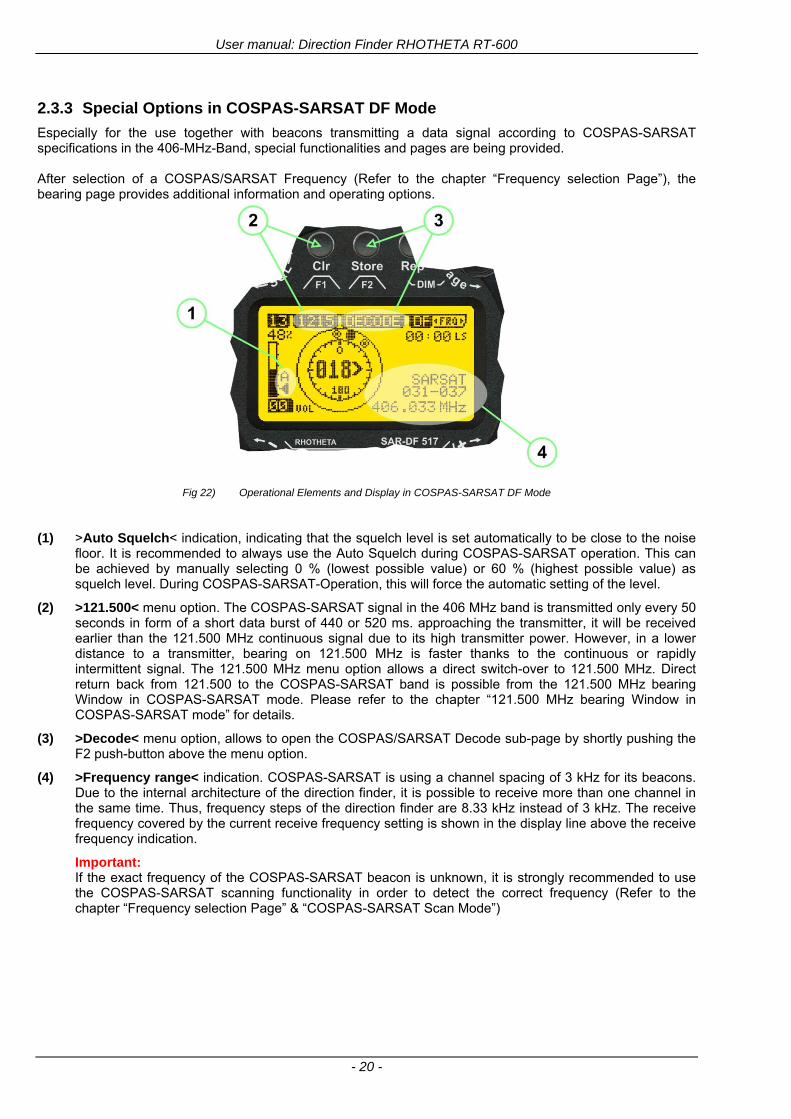
User manual Direction Finder RHOTHETA RT-600
- 20 -
233 Special Options in COSPAS-SARSAT DF Mode
Especially for the use together with beacons transmitting a data signal according to COSPAS-SARSAT specifications in the 406-MHz-Band special functionalities and pages are being provided After selection of a COSPASSARSAT Frequency (Refer to the chapter ldquoFrequency selection Pagerdquo) the bearing page provides additional information and operating options
Fig 22) Operational Elements and Display in COSPAS-SARSAT DF Mode
(1) gtAuto Squelchlt indication indicating that the squelch level is set automatically to be close to the noise
floor It is recommended to always use the Auto Squelch during COSPAS-SARSAT operation This can be achieved by manually selecting 0 (lowest possible value) or 60 (highest possible value) as squelch level During COSPAS-SARSAT-Operation this will force the automatic setting of the level
(2) gt121500lt menu option The COSPAS-SARSAT signal in the 406 MHz band is transmitted only every 50 seconds in form of a short data burst of 440 or 520 ms approaching the transmitter it will be received earlier than the 121500 MHz continuous signal due to its high transmitter power However in a lower distance to a transmitter bearing on 121500 MHz is faster thanks to the continuous or rapidly intermittent signal The 121500 MHz menu option allows a direct switch-over to 121500 MHz Direct return back from 121500 to the COSPAS-SARSAT band is possible from the 121500 MHz bearing Window in COSPAS-SARSAT mode Please refer to the chapter ldquo121500 MHz bearing Window in COSPAS-SARSAT moderdquo for details
(3) gtDecodelt menu option allows to open the COSPASSARSAT Decode sub-page by shortly pushing the F2 push-button above the menu option
(4) gtFrequency rangelt indication COSPAS-SARSAT is using a channel spacing of 3 kHz for its beacons Due to the internal architecture of the direction finder it is possible to receive more than one channel in the same time Thus frequency steps of the direction finder are 833 kHz instead of 3 kHz The receive frequency covered by the current receive frequency setting is shown in the display line above the receive frequency indication
Important If the exact frequency of the COSPAS-SARSAT beacon is unknown it is strongly recommended to use the COSPAS-SARSAT scanning functionality in order to detect the correct frequency (Refer to the chapter ldquoFrequency selection Pagerdquo amp ldquoCOSPAS-SARSAT Scan Moderdquo)
User manual Direction Finder RHOTHETA RT-600
- 21 -
234 COSPAS-SARSAT Decode Window
The COSPAS-SARSAT Decode Window allows decoding incoming COSPAS-SARSAT data messages Only while this decode window is activated the decoding is possible An already received COSPAS-SARSAT puls while DF bearing mode was activated can not be used for decoding afterwards In this case the user has to wait while this decode window is active for the next transmitted puls approx 50 sec later
Fig 23) COSPAS-SARSAT Beacon Information Page
(1) gtExitlt push button (F1 button) allows to exit the decode window and switch back to the COSPAS-
SARSAT DF Mode page
(2) gtSARSATlt in the upper right corner of the display indicates that the COSPAS-SARSAT decode function is activated
(3) gtCountrylt displays the COSPAS-SARSAT Country Code coded into the received data message
(4) gtLast Signallt time since the last COSPAS-SARSAT message has been received in minutes secondsrsquo format
(5) gtPositionlt field showing in case of location protocols being used by the beacon the encoded GNSS position data (latitude longitude) transmitted by the beacon
(6) gt15-HEX-IDlt 15-HEX-ID of the beacon in hexadecimal format
(7) gtData stringlt of the bits 25 to 112 of the COSPAS-SARSAT data burst in case of short messages and bits 25 to 144 in case of a long message format The last 8 Hex Values are separated by a blank Bit- and Frame-synchronization hex values (Bits 1 to 24) are suppressed to increase the readability of the data message
(8) gtXlt sign to indicate that the Squelch is controlled by the antenna unit for optimum sensitivity The user has no access to the Squelch setting
User manual Direction Finder RHOTHETA RT-600
- 22 -
235 Tracking 121500 MHz while in COSPAS-SARSAT Mode
While in COSPAS-SARSAT DF Mode the user can switch to 121500 MHz in order to track the beacon in VHF If a valid signal is not received in 121500 MHz the user can switch back to the last active COSPAS-SARSAT channel (406 MHz frequency) being tracking previously
Fig 24) Tracking 121500 MHz while in COSPAS-SARSAT Mode
Differences are (1) gt406xlt press F1 to switch back to the last
COSPAS-SARSAT channel (406 MHz frequency) being tracking previously
(2) gt121500 MHzlt Actual frequency being tracked
User manual Direction Finder RHOTHETA RT-600
- 23 -
236 COSPAS-SARSAT Scan Mode
If the COSPAS-SARSAT Scan Mode has been selected at the frequency selection page ldquoFRQrdquo the COSPAS-SARSAT channels as selectable manually from the Frequency Selection Page are scanned After reception of a COSPAS-SARSAT Signal the scanning is stopped at the received frequency Due to the fast scanning ndash the complete COSPAS-SARSAT sub-band is scanned within less than 400 ms ndash detection of a receivable COSPAS-SARSAT signal is possible within one COSPAS-SARSAT repetition cycle
Fig 25) FRQ Selection Page with SCN COSPAS-SARSAT Scan Page selected
At the frequency selection page an active COSPAS SARSAT scanning can be stopped by de-activating it with the rotary button (1) While the scanning is active it is also possible by pressing gtF1lt ldquoEXITrdquo to switch back to the DF pagehellip
Fig 26) DF page with active COSPAS-SARSAT Scan Mode at the DF page
(1) gtSCANlt flashing indication notifying the user that the equipment is operating in scan mode
(2) Frequency display indicating the COSPAS-SARSAT scanning frequency range
(3) gtXlt sign showing that squelch settings are controlled autonomously by the receiver
Scan mode can be left by pressing gtF1lt ldquoSTOPrdquo
User manual Direction Finder RHOTHETA RT-600
- 24 -
237 Marine Ship Scan Mode
Fig 27) DF Mode FRQ = 156800 MHz F1 for scan function
If the active frequency (2) is within the VHF Marine Band a fast scan of all ship channels is possible by pushing gtF1lt ldquoSCAN (1) In this scanning mode all marine channels 1 to 88 (156025 to 157450 MHz) are scanned continuously until a signal is received To offer the best monitoring functionality for the user also signals between to channels (4) are detected (scanning without gap) In order to prevent the scan to stop on noisy frequencies it is recommended to start scanning with high squelch settings You can reduce the squelch level in steps until the scan stops on a noisy frequency for the first time Then increase the squelch level slightly This will result in the highest possible scan sensitivity and avoiding noisy channels due to RF disturbances sometimes generated by other equipment in own aircraft
Fig 28) DF Mode active scanning in process
The scanning is stopped by pressing gtF1lt ldquoSTOPrdquo (3)
User manual Direction Finder RHOTHETA RT-600
- 25 -
24 Law Enforcement Operation Law enforcement special ops and other organizations use the RT-600 LE (LAW ENFORCEMENT) version instead of the RT-600 A (STANDARD) version One of the reasons is that the LE version features scanning and tracking of signals like LoJack and ETS as well as signals in the 216000 MHz ndash 220000 MHz band such as medical beacons wristankle transmitters cashasset recovery ldquotagsrdquo etc However the LE version shares many functions in common with the A version such as scanning and tracking in the AIR band COSPAS-SARSAT band etc
241 Power-On procedure
The power-on procedure is the same as described in 211
(1) System Version ldquo(L)rdquo for LAW ENFORCEMENT version
Fig 29) STARTUP Screen (see 211 for details)
242 LoJack Scan Mode Start scanning for a VLU Code
For the convenience of Law Enforcement and other special ops users who frequently engage in tracking SVRS (Stolen Vehicle Recovery System) signals such as LoJack (LoJack Corp FCC 9020 Part 2 SVRS) RHOTHETA has optimized the power-on procedure of the RT-600 LE version so that right after the STARTUP screen the unit displays automatically the LoJack Scan Mode page to start immediately scanning for a valid VLU (Vehicle Location Unit) code without pressing any key
Fig 30) LoJack Scan Mode unit is scanning for a LoJack VLU Code
(1) gtscan LoJacklt DF is scanning for any new LoJack VLU Code
(2) gtEXITlt press F1 to exit and switch directly to DF Mode
User manual Direction Finder RHOTHETA RT-600
- 26 -
243 LoJack Scan Mode from any other page
While operating on any page other than the LoJack Scan page the user can switch directly to LoJack Scan Mode by pressing Hotkey F2 for 2 secs
(1) press Hotkey F2 for 2 secs to switch to the LoJack Scan page
Fig 31) Hotkey F2
User manual Direction Finder RHOTHETA RT-600
- 27 -
244 Manual activation of LoJack Scan Mode
(1) select the LoJack frequency (see also Frequency Selection Page)
(2) press F1 to switch back to the DF MODE
Fig 32) FRQ Selection Page FRQ = LoJack BAND = LoJack (164-174 MHz)
While in DF MODE with adjusted LoJack frequency the user can switch directly to the LoJack Scan by pressing gtF1lt ldquoSCANrdquo
(1) press F1 SCAN to switch to the LoJack Scan page
(2) still no LoJack ID filter used (ID=off) all transmissions are received on the active frequency as example also unwanted tower pulses
Fig 33) DF Mode with LoJack filter OFF
User manual Direction Finder RHOTHETA RT-600
- 28 -
245 Receiving and accepting a new VLU Code
While in LoJack Scan Mode waiting for a VLU Code if a new VLU Code is displayed the user can accept it and switch directly to DF Mode by pressing F2
(1) a new LoJack VLU Code (0001A) has been received
(2) press F2 to accept the new VLU Code (0001A) and switch to DF MODE page with the LoJack filter activated to track only 0001A
Fig 34) LoJack Scan Mode with new VLU Code received
246 Entering a new VLU Code manually
While in LoJack Scan Mode the user can enter a LoJack VLU code also manually
(1 2 3) use the SELECTplusmn and plusmnVALUE knobs to enter a new LoJack VLU Code active ID (0001A)
(4) Press F1 to accept the new VLU Code and switch to DF Mode with the LoJack filter ON to track only 0001A
Fig 35) LoJack Scan Mode with new VLU Code entered manually
User manual Direction Finder RHOTHETA RT-600
- 29 -
247 Tracking one VLU Code while monitoring new VLU Codes
While on DF Mode and tracking a VLU Code (0001A) the user can turn the LoJack switch OFF with F2 also the user can start scanning all VLUs again with F1
0001A is displayed as the active VLU Code filter function is ON only 0001A is tracked
Monitoring of other VLU Codes is active in the background
(1) Press F1 to switch to the LoJack Scan Mode to scan for new VLU Codes
(2) Press F2 to switch LoJack filter OFF
Fig 36) DF Mode with active VLU Code and LoJack filter ON
248 Tracking one VLU Code and receiving a new VLU Code
While on DF MODE page and tracking VLU Code (0001A) in the background a new VLU Code is received and decoded (G2HC7)
(1) The new VLU Code is announced (NEW G2HC7)
(2) Press F1 to switch to LoJack Scan Mode to see the arrival time of G2HC7 and the possibility to change bearing to this new G2HC7
Fig 37) DF Mode with active VLU Code and announcement of new VLU Code
User manual Direction Finder RHOTHETA RT-600
- 30 -
249 Switching to a new VLU Code
While on the LoJack Scan Page tracking one VLU Code (0001A) and notified of a new VLU Code (G2HC7)
(1) press F1 to continue tracking 0001A
(2) press F2 to start tracking G2HC7
(3) Time elapsed since G2HC7 was last received
(4) Time elapsed since 0001A was last received
If F1 is pressed for 2 sec the indicated VLU Code (G2HC7) and ID (0001A) are deleted
Fig 38) LoJack Scan Page with one active VLU Code and one new VLU Code
2410 ldquoBlockingrdquo function of one LoJack VLU Code
The LoJack scan page can also be used to ldquoblockrdquo one unwanted LoJack VLU ID signal by separating the adjusted active ID from any other received LoJack VLU signal This is done by muting the audio (see example below) when a LoJack signal with VLU code ldquo0001Ardquo is received gtgt Any new VLU Code (active LoJack signal) - except for 0001A ndash will be displayed on the top row and generate the audible beep tone
Fig 39) LoJack Scan Page with one active VLU Code and audio OFF
Tip ldquoBlockingrdquo is an important tool for practical missions As example a stolen vehicle with VLU ID ldquo0001Ardquo was tracked in the DF bearing mode The mission
is completed but the VLU is normally still transmitting With the settings above only new VLU signals except the now unwanted ldquo0001Ardquo are audible and displayed in the upper (scan LoJack hellip for new VLU) box
User manual Direction Finder RHOTHETA RT-600
- 31 -
2411 Tracking in the 216 to 220 MHz band
The RT-600 features scanning and bearing functionality in the 216000 MHz to 220000 MHz band The 216000 MHz ndash 220000 MHz band contains frequencies and signals used by special services and tracked by law enforcement special ops and similar organizations These are some of the frequencies and services in this band
CFR 90259 tx 216000 MHz to 220000 MHz
Low Power Radio Service (LPRS) tx 216000 MHz to 217000 MHz
Medical beacons Project Lifesaver tx wristankle tx 213000 MHz to 216000 MHz
ETS tx stolen cashasset recovery tx ldquobaitrdquordquotagrdquo tx 216000 MHz to 220000 MHz tx = transmitter(s) However any future or current user of the Rhotheta RT-600 must be aware that tracking signals on the frequencies listed above may be challenging and even frustrating due mostly to negative factors in some of the transmitters
bull Very low RF power output
bull Inefficient antennas
bull Battery-powered devices with a ldquolow batteryrdquo condition
bull Devices worn or located in conditions of poor RF propagation
bull Devices with channel spacing different than the one specified for the RT-600
These factors can make it very difficult for the DF to receive the signal andor display an accurate bearing Disclaimer For the reasons explained above and even though the RT-600 features top performance in its class RHOTHETA does not offer - and is not to be held responsible for - any guaranteed minimum range or distance to a transmitter in this band
25 Setup Edit Page System settings are displayed in the setup page The functions described in this section should be used by trained personal only
Fig 40) Accessing the Setup Page
The setup page can be accessed by holding down the gtCLRlt (1) and gtREPlt (2) buttons simultaneously and in the same time performing a left-hand turn on the gtPagelt rotary switch (3)
User manual Direction Finder RHOTHETA RT-600
- 32 -
Fig 41) Setup Page
(1) gtStorelt push-button must be pressed in parallel if a value of a setting shall be modified If a value can
be modified the background stops to blink
(2) gtSelectlt rotary switch used to scroll through the menu options The value of the actually activated menu option is high-lighted with dark background and blinking
(3) gtValuelt rotary switch used to change values in menu options (gtStorelt (1) has to be pressed in parallel if a value shall be modified)
(4) gtSN-Ratiolt menu option representing the necessary Signal-To-Noise-Ratio (Difference between signal and noise level) used as criterion for the automatic squelch function Please refer to the chapter ldquoSquelch Operationrdquo for details Default value is 60 dB
(5) gtMounting Positionlt menu option to select Top- or Bottom-Mounting of the DF antenna In case of rooftop installation (eg on land vehicles) ldquoToprdquo shall be selected In case of bottom-down (upside-down) installation (eg on a helicopter) ldquoBotrdquo shall be selected If this option is not selected correctly all bearing values will be mirror-inverted
(6) gtBearing Offsetlt menu option to include a constant offset correction to the bearing indication Bearing values in degrees will be changed according to the offset value
(7) gtMaximum External Dimming Voltage for Legendslt menu option which sets the upper limit of the dimming input voltage for the legends-panel Range=[15 hellip 28]V
(8) gtMinimum External Dimming Voltage for Legendslt menu option which sets the lower limit of the dimming input voltage for the legends-panel Range=[15 hellip 28]V
(9) gtPagelt rotary switch to be turned right-hand to go back to the Direction Finder page A left-hand turn on this rotary switch will show up an additional service page with debug information used for system checks
(10) gtExtended Seriallt It is possible to enable or disable the extended serial data protocol Only of interest if serial data is used by any connected control units like moving maps or computers For detailed information see (Serial interface data protocol (short description)gt at page 46) If there are compatibility problems with already existing older remote control software it is recommended to switch OFF the extended serial data protocol
User manual Direction Finder RHOTHETA RT-600
- 33 -
3 Error messages If an internal error of the device is recognized a corresponding flashing error message will be shown in the DF pages
Fig 42) Error Messages
(1) Error message including error code (in brackets)
(2) Short description of the indicated error
In case of coincidence of various errors the error with the highest priority will be displayed
Error message Error location Reason
Error (12) VOLTDU
Main voltage supply Main Voltage input too low ( 100 V)
Error (11) NO AU
Connection antenna display or Antenna Unit
No serial data (RS485) from Antenna Unit No or damaged connection between antenna and display or damaged antenna unit
Error (10) BAD AU
Connection antenna display
Incompatibility or bad data connection between display and antenna
Error (9) BAD RU
Remote Unit Incompatibility or bad data connection between display and external serial Remote Unit or PC
Error (8) VOLTAU
Antenna Unit Voltage supply at Antenna Unit too low ( 90 V) Main voltage supply too low or considerable drop of voltage between display and antenna
Error (7) BAD DCU
Connection Display Antenna
Incompatibility or bad data connection between antenna and display
Error (6) NO DCU
Connection Display Antenna
No serial data from Display Control Unit to Antenna Unit
Error (5) PLL ERR
antenna Error in synthesizer-oscillator of receiver in Antenna Unit
Error (4) FRQ+OFS
received transmitter Received frequency too high (more than 6 KHz error of transmitter)
Error (3) FRQ-OFS
received transmitter received frequency too low (more than 6 KHZ error of transmitter)
Error (2) DECODE
radio distance transmitter DF
Data Bits of decoded signal (COSPAS-SARSAT or LoJack) defective
Error (1) DATARNG
Incompatibility of data DCU AU
Protocol data bytes out of valid range
Error (0) NO REC
Antenna Unit receiver
Receiver board defective
User manual Direction Finder RHOTHETA RT-600
- 34 -
4 Installation
41 Antenna unit A convenient position of the monopole bearing antenna is crucial for good bearing results The antenna needs an effective ground connection to the body of the aircraft or to the roof of the vehicle If there is no metallic mounting surface available a metallic sheet or similar (net) with connection to ground has to be applied first between vehicle-body and antenna In this hatched area the antenna touches the body ofthe vehicleaircraft In order to obtain a good groundconnection the surface of the body should be bared(Measuring unit [mm])
8 x holes for mounting the antenna unit to the
vehicle aircraft
Fig 43) Antenna Mounting Drawing
User manual Direction Finder RHOTHETA RT-600
- 35 -
411 Influence of antenna location and environment on the bearing accuracy
Recommendations concerning the practical antenna unit location on helicopters and airplanes
The bearing accuracy of the direction finder antenna unit is severely influenced (comparable to an airspeed sensor) by the environment For comparison a perfect high quality speed sensor will not indicate the true airspeed if this sensor is interfered by strong turbulences The direction finder antenna unit acts as a sensor for electromagnetic waves In the near field of this antenna unit any conductive (eg metallic) obstacle will influence the incoming wave field and create reflections which decrease the bearing accuracy These are general physical limitations concerning all types of direction finder systems To achieve the best bearing results it should be considered that the antenna unit is installed as far away as possible from any other vertically polarized conductive structure If possible there should be no reflectors within an area of 2-3 feet around the antenna unit In this worst case example the direction finder will not work properly
Fig 44) Antenna Installed in a Bad Location
In this example the antenna unit is located too close to the cable cutter of the helicopter This cutter will produce strong reflections especially as the length is equal to Lambda4 within the VHF airband
User manual Direction Finder RHOTHETA RT-600
- 36 -
Examples of properly installed direction finder antenna units
Fig 45) Antenna Installed in Good Locations
User manual Direction Finder RHOTHETA RT-600
- 37 -
42 Display and Control Unit
The display control unit may be mounted into a front panel by the means of this mounting drawing
Fig 46) DCU Mounting Drawing
(all dimensions in [mm]) To install or uninstall the display control unit perform the following steps (1) Remove the cover caps of the four rotary switches
(2) Loose the screws visible below the position of the cover caps
(3) Remove the plastic button from the axis of the four rotary switches
(4) Mount dismount the display control unit
(5) Re-install the plastic buttons on the axis of the four rotary switches
(6) Fix the screws so that the plastic buttons are fixed on the axis
(7) Re-install the cover caps on the four rotary switches
User manual Direction Finder RHOTHETA RT-600
- 38 -
43 System Interconnect Wiring Diagram (Also refer to chapter ldquoTechnical Datardquo for details)
Fig 47) System Interconnect Wiring Diagram
6-pol Amphenol plug femalePTG06SE10-6S(SQ)
max length of cable 20 m 9-pol Sub-D plug (femalemale)
User manual Direction Finder RHOTHETA RT-600
- 39 -
5 Technical Data
51 Electric features
Method of bearing Doppler-principle (3 kHz rotational frequency right left rotation)
Bearing accuracy1 plusmn 5deg RMS
Internal resolution 1deg
Bearing Sensitivity VHF AirEmergency le 25 μVm (typical)
VHF Marine le 25 μVm (typical)
UHF Emergency and ETS le 4 μVm (typical)
COSPAS-SARSAT le 4 μVm (typical)
LoJack Decoding (50 Message Error Rate) and bearing le 5 μVm (typical)
Frequency stability plusmn 20 ppm (Δff = plusmn210-6)
Reception frequencies
SAR version (Standard)
Frequency Options
VHF Emergency Band 118000 to 124000 MHz (833 kHz steps AM)
VHF Marine Band 154000 to 163000 MHz ( 500 kHz steps FM) (channel 16 selectable via channel no)
UHF Emergency Band 240000 to 246000 MHz (2500 kHz steps AM)
UHF FM Band 406100 to 410000 MHz ( 500 kHz steps FM)
COSPAS-SARSAT 400000 to 406092 MHz Including 406022 to 406076 MHz (Channel A S)
F1 VHF Air Band 118000 to 136992 MHz
F2 extended VHF Marine Band 137000 to 224995 MHz
F3 extended UHF Air Band 225000 to 399975 MHz
F4 additional UHF FM Band 406100 to 470000 MHz
Reception frequencies
LAW Enforcement version
Frequency Options
VHF Emergency Band 118000 to 124000 MHz (833 kHz steps AM)
VHF Marine Band 154000 to 163000 MHz (500 kHz steps FM) (channel 16 selectable via channel no)
LoJack 164000 to 174000 MHz (125 kHz steps FM)
ETS 216000 to 220000 MHz (10125 kHz AM)
COSPAS-SARSAT 400000 to 406092 MHz Including 406022 to 406076 MHz (Channel A S)
F1VHF Air Band 118000 to 136992 MHz
F2 extended VHF Marine Band 137000 to 163000 MHz
COSPAS-SARSAT fast scan mode
Full automatic detection of any active COSPAS-SARSAT channel A to S within 400 ms
COSPAS-SARSAT decoding
Reception and decoding of COSPAS-SARSAT data signal (112 or 144 bit) specified according to COSPAS-SARSAT
LoJack decoding Selectable LoJack ID display and selective active filtering
Special scanning modes
complete maritime ship band scanning within 3 s (channel 01 hellip 88 also frequencies between 2 channels are included)
1With undisturbed wave field and sufficient field strength Measuring by changing the angle of incidence with the antenna rotating on a revolving table in order to eliminate environmental influences on the results No modulation
User manual Direction Finder RHOTHETA RT-600
- 40 -
Bearable modulation A3E F3E A3X (ELT-modulation) F1D G2D COSPAS-SARSAT Bearing largely independent of modulation
Polarization Vertical
Polarization error 5deg at 60deg field vector rotation
Garbling cone Ca 30deg to the vertical
Time of response2 50 ms (with sufficient reception field strength)
LC-graphic display 128 x 64 pixels supertwist transflective extended range of temperature dark-blue display on yellow-green background background light Freely adjustable (exponential) dimming of brightness
NVG cockpit design Fully compatible NVIS Green B display Control Unit optional
Operating voltage 275 V nominal 12 V to 35 V DC
Current consumption LCD-background light Off max 500 mA (12 V DC) max 250 mA (24 V DC)
LCD-background light 100 max 750 mA (12 V DC) max 350 mA (24 V DC)
LCD-background light 100 max 900 mA (12 V DC) with NVG Option max 400 mA (24 V DC)
Audio out For external speaker approx 2 W (4 Ω)
Serial data interface Serial interface RS-232 (9600 baud 8 data bits 1 stop bit no parity)
2Very weak signals can considerably increase the time of response
User manual Direction Finder RHOTHETA RT-600
- 41 -
52 Interface External connections (optional at Sub-D 9-pol Male connector)
Dimming
Pin 8
external voltage input for variable dimming of legends
(optional)
Analog input signal for variable control of the legends illumination Input voltage range is freely adjustable in the range of 15 hellip 28 V in the setup menu Refer to chapter ldquoSetup Pagerdquo Default setting 8 hellip28 V (8 V = Off 28 V = max dimming for legends)
Input Impedance gt 50 k
Pin 6 night status line for LCD
dimming (optional)
Low-active (as example switch to ground) At input voltage lt 25 VDC the LCD dimming operates in nightNVG mode Maximum brightness ca 4 of daydefault mode brightness
Input Impedance gt 50 k
Pin 4 NVG status line for LCD
dimming (optional)
Low-active (as example switch to ground) At input voltage lt 25 VDC the LCD dimming operates in nightNVG mode Maximum brightness ca 4 of daydefault mode brightness
Input Impedance gt 50 k
AudioLF
Pin 7 Audio output signal
AC coupled voltage source with very low inner resistance Maximum output voltage ca 8 VPP = 283V RMS at maximum Volume Maximum output power ca 2 W with 4 speaker
If a headphone is connected ([32hellip600] 100mW) we recommend using a resistor (18 025 W) between audio output and headphone to prevent damage of the headphone
Serial interface RS232 (9600 baud 8 data bits 1 stop bit no parity)
Pin 3 TXD Serial output (ca plusmn10 V)
Pin 2 RXD Serial input (ca plusmn10 V)
User manual Direction Finder RHOTHETA RT-600
- 42 -
53 Mechanical features
Temperature range
Display Control Unit permissible operating temperature3 -20 degC +60 degC permissible storage temperature -30 degC +80 degC
Antenna Unit permissible operating temperature3 -40 degC +60 degC permissible storage temperature -55 degC +80 degC
Protective system Antenna Unit IP 67
Weights Display Control Unit 250 g Antenna Unit 2000 g
Dimensions Display Control Unit 82 mm x 82 mm x 43 mm (width x height x depth) Antenna Unit 270 mm x 185 mm
Fig 48) DCU Mechanical Drawing (all dimensions in [mm])
3 For temperatures lower than ndash10deg C a warm-up period of 15 min should be allowed
User manual Direction Finder RHOTHETA RT-600
- 43 -
Fig 49) AU Mechanical Drawing (all dimensions in [mm])
User manual Direction Finder RHOTHETA RT-600
- 44 -
6 Appendix
61 Frequency Ranges
User manual Direction Finder RHOTHETA RT-600
- 45 -
62 Frequencies of channels on maritime band (only for standard [A] version) Frequency-range of the RT-600 in the maritime band 156000 MHz 162025 MHz
Channel No frequency (ship - station) Frequency (coast - station)
1 156050 MHz 160650 MHz 2 156100 MHz 160700 MHz 3 156150 MHz 160750 MHz 4 156200 MHz 160800 MHz 5 156250 MHz 160850 MHz 6 156300 MHz 160900 MHz 7 156350 MHz 160950 MHz 8 156400 MHz 9 156450 MHz
10 156500 MHz 11 156550 MHz 12 156600 MHz 13 156650 MHz 14 156700 MHz 15 156750 MHz 16 156800 MHz 17 156850 MHz 18 156900 MHz 161500 MHz 19 156950 MHz 161550 MHz 20 157000 MHz 161600 MHz 21 157050 MHz 161650 MHz 22 157100 MHz 161700 MHz 23 157150 MHz 161750 MHz 24 157200 MHz 161800 MHz 25 157250 MHz 161850 MHz 26 157300 MHz 161900 MHz 27 157350 MHz 161950 MHz 28 157400 MHz 162000 MHz 60 156025 MHz 160625 MHz 61 156075 MHz 160675 MHz 62 156125 MHz 160725 MHz 63 156175 MHz 160775 MHz 64 156225 MHz 160825 MHz 65 156275 MHz 160875 MHz 66 156325 MHz 160925 MHz 67 156375 MHz 68 156425 MHz 69 156475 MHz 70 156525 MHz 71 156575 MHz 72 156625 MHz 73 156675 MHz 74 156725 MHz 75 156775 MHz 76 156825 MHz 77 156875 MHz 78 156925 MHz 161525 MHz 79 156975 MHz 161575 MHz 80 157025 MHz 161625 MHz 81 157075 MHz 161675 MHz 82 157125 MHz 161725 MHz 83 157175 MHz 161775 MHz 84 157225 MHz 161825 MHz 85 157275 MHz 161875 MHz 86 157325 MHz 161925 MHz 87 157375 MHz 161975 MHz 88 157425 MHz 162025 MHz
User manual Direction Finder RHOTHETA RT-600
- 46 -
63 Serial interface data protocol (short description)
631 General
Interface parameters RS232 9600 Baud 8 databits 1 stopbit no parity LSB sent first Timing of serial data For accurate use of the serial data (even for the optional serial input commands) the correct timing is mandatory The DCU (Display Control Unit) sends out via the RS-232 Pins (see 43 System Interconnect Wiring Diagram page 38) cyclic and autonomous every approx 250300 ms a binary data stream which contains all relevant DF-bearing information The output data contains one or two blocks of binary data (see next picture with accordingly description) The optional serial input is only used if changes (as example frequency change) are done by additional remote control units
Fig 50) Timing of serial data
Serial standard output
This output data is always available and contains all relevant DF-bearing data For detailed content see page 47
Optional extended serial output
This data contains some additional information like as example CospasSarsat or LoJack decoding and ID data For detailed content see page 50 The data is only available with DCU Software [Rev ge 320] and if this optional data block is configured as ON = enabled (see Setup Edit Page point (10) )
Even to avoid compatibility problems with already existing older remote control software it is possible to disable switch off this additional data block (see Setup Edit Page point (10) )
Optional serial input
Only used for optional commands to control DCU parameters If as example the direction finder frequency is changed remotely there is send to the DCU one time this data block with the new frequency For detailed content see page 52
User manual Direction Finder RHOTHETA RT-600
- 47 -
632 Serial standard output (protocol description)
Specification serial standard output
The binary data stream with a length of 39 bytes starts with a header byte (value = hex 0xA0 as ID for DF Mode) The next bytes contain different values for status bearing information and also service The last byte is used for data stream checksum control Remark This is a binary data protocol So every byte value from 0dec hellip 255dec (0x00 hellip 0xFF) is possible Because of this it is not allowed to realize a start byte detection by the content (0xA0) The idle line detection is recommended for detection the end of message Register of databytes (for details see next page)
byte no
[0] Header = 0xA0 Id for DF Mode
[1] Number = 39 = bytes in the complete message (including header and checksumbyte)
[2] Status (1) HSB [x|x|x|x|x|x|x|x] LSB | | | | | | | --gt (0) Receiving | | | | | | ----gt (1) Squelch controlled by AU (X) | | | | | ------gt (2) Permission RL Calibration | | | | --------gt (3) Line Night | | | ----------gt (4) Line NVG | | ------------gt (5) Dimming External | --------------gt (6) Autosquelch Active ----------------gt (7) 0=Standard Version 1=LE Version
[3] Status (2) HSB [x|x|x|x|x|x|x|x] LSB | ----------------gt (7) 0=Standard 1=extended serial dataprotocol = ONactive
[45] Error (Bits[120])
[6] Actual DCU Page
[7] Volume [0hellip100]
[811] Frequency [Hz]
[12] Active Band
[13] Actual Squelchlevel [0hellip60]
[14] Audio-Line amp_NF_Test Output
[15] (Not used)
[1617] Voltage_DCU ([0hellip335]=[0 hellip 335]V
[1819] Voltage_AU ([0hellip255]=[0 hellip 255]V
[20] Temperature_AU [-68hellip+127]degC
[21] Frequency Offset [-99hellip+99]
[2225] ServiceTest values (mode dependent test values for service only)
26 (Not used reserved)
[27] Level [0hellip100]
[2829] Bearing Averaged [0hellip359]deg relative
[3031] Bearing Live_Min [0hellip359]deg relative
[3233] Bearing Live_Max [0hellip359]deg relative
[34] Test Value PS-RAM Right Rotation[0hellip178] (for service only)
[35] Test Value PS-RAM Left Rotation [0hellip178] (for service only)
[3637] (Not used reserved)
[38] Checksum is the 2rsquos complement of the modulo-256 sum of all bytes without checksum-byte [0n-1]
User manual Direction Finder RHOTHETA RT-600
- 48 -
Detailed Description of important values for practical use
Status byte [2] Receiving Bit 0 of this value (LSB) indicates signal receiving Bit 0 = 0 then no signal is received and so on no bearing is available Bit 0 = 1 then bearing is possible Bit 1 if(1) then Squelch is controlled by AU (active at modes CospasSarsat Decode CospasSarsat Scanning LoJack with Filter=ID only)
Error bytes [4hellip5] 16 bit value each set bit corresponds to the error no (Refer to the chapter Error messages) Example - 0x0000 No error - 0x0800 Bit No 11 Set ( = No AU Error)
Actual DCU Page byte [6] indicates actual operating mode of DCU 0 = Standard bearing page 1 = Frequency memory page 2 = CospasSarsat decoding page 3 = LoJack decoding page (ID edit)
Frequency bytes [8hellip11] 32 bit value actual adjusted frequency [Hz] Example - 0x073DF160 1215000000 121500 MHz
Active Band Standard Version [A] 0=VHF Airband 1=VHF Marineband sea 2=VHF Marineband coast 3=UHV Airband 4=CospasSarsat LE Version [L] 0=VHF Airband 1=LoJack 2=Lifesaver 3=ETS 4=CospasSarsat
Actual Squelchlevel byte [13] Range [0hellip60] without signal the actual squelchlevel should always be adjusted a little bit over the noise level (Refer to the chapter Squelch operation)
Level byte [27] Range [099] actual receiving level (without signal this value is equal to the noise level) If a signal is received then this value corresponds to the signal strength of this signal
Relative Bearing averaged byte [2829] 16 bit value Range [0hellip359 0xFFFF] if the value = 0xFFFF then no valid bearing is available otherwise this value contains the actual averaged bearing information in Deg [0deg359deg] Example - 0X0114 276deg bearing (= left side oriented to heading)
Bearing Live MinMax byte[3031] amp [3233] - 16 bit values Range [0hellip359 0xFFFF] Only for signal quality or additional information ndash NOT recommended for bearing indication The relative live bearing field contains the maxmin bearing in degrees without averaging The relative live bearing reacts faster than the normal relative bearing but it has not the precision of the averaged bearing The MinMax Bearing Values are calculated within a time period of approx 250 ms If they are very close together (for example ldquo124rdquo and ldquo128rdquo degrees) then the signal quality is quite good A wide span of the minmax values (for example ldquo97rdquo and ldquo162rdquo) shows very noisy but nevertheless bearable signal quality
User manual Direction Finder RHOTHETA RT-600
- 49 -
633 DCU Info output (protocol description)
Specification DCU Info output
Remark This protocol is only available while the SetupEdit page is activated at the DCU
byte no
[0] Header = 0xAF Id for DCU Info Mode
[1] Number = 39 = bytes in the complete message (including header and checksumbyte)
[2]
(see standard output) [3]
[45]
[621] Info String of 15 byteschars the string contains Information about Unit Variant Software Version and Serial No
Example Byte [318] =
|--AU ID---||Var-||---Software Version---| |-------------- Serial No---------------| [0x44][0x55][0x41][0x33][0x2E][0x33][0x30][0x3A][0x20][0x20][0x30][0x31][0x32][0x33][0x34][0x00] rsquoDrsquo rsquoUrsquo rsquoArsquo rsquo3rsquo rsquorsquo rsquo3rsquo rsquo0rsquo rsquorsquo rsquo rsquo rsquo rsquo rsquo0rsquo rsquo1rsquo rsquo2rsquo rsquo3rsquo rsquo4rsquo rsquoENDrsquo | | | | __________________ | | ________________________ | n n n | | n n n n n | (Software Version) | | (Serial No) | gt rsquoArsquo = Standard Variant gt rsquoLrsquo = Law Enforcement Variant
User manual Direction Finder RHOTHETA RT-600
- 50 -
634 Optional extended serial output (protocol description)
The data content depends on the actual mode of the direction finder To get special data the direction finder has first to be switched to the equivalent mode
COSPAS-SARSAT Decoding data
This data is only available and valid if Display Control Unit with actual software Rev ge 320 (see Power-On procedure page 10) Configuration of Extended serial = ON (see Setup Edit Page point (10) ) Direction Finder COSPAS-SARSAT decoding mode is activated by selecting the corresponding page
(see COSPAS-SARSAT Decode Window page 20 and page 21) and so on Header (byte 0 of data) = 0x91
A valid COSPAS-SARSAT decoding data protocol is always marked by the first data byte (header = 0x91) Always after receiving and decoding of a valid COSPAS-SARSAT pulse the complete data protocol with 33 bytes is send out one time
Byte No
[0] Header = 0x91 (Identification for CPSarsat decoding mode)
[1] Number of bytes - 7 if no decoded pulse is available - 33 if new pulse was received and is available
[2] Error
[3] Bit[0] - 0 =gt No new 406 MSG (decoded data) available - 1 =gt New valid 406 MSG available (Sync amp Frame Ok) Check Error Status for Bit-Errors
Bit[61] AutoSquelch Level valid range [060] ( decimal)
Bit[7] = 1 Squelch controlled by AU
[4] Signallevel of received signal valid range [099] ( decimal)
[5] Voltage of Antenna Unit Power Supply input valid range [80255] (decimal = 80 255 V DC)
[6] Temperature inside Antenna Unit valid range [-50+100] (degC signed byte value)
The following databytes are only available if a correct CPSarsat puls gets received and decoded with correct checksum
[724] 18 x Databytes complete orginal CPSarsat 406 decoded message (144 bit)
Databyte Nr [ Byte 7 ] [ Byte 8 ] [Byte9 Byte24] 406 MSG Bit Nr [1 2 3 4 5 6 7 8] [9 10 11 12 13 14 15 16] [17 144]
[25] SN-Flag valid values 0x53=rsquoSrsquo 0x4E=rsquoNrsquo 0x2D=rsquo-rsquo if no GPS data available
GPS-Position Latitude
[26] Deg valid values [090] (decimal Deg) 0xFF if no GPS data available
[27] Min valid values [059] (decimal Deg) 0xFF if no GPS data available
[28] Sec valid values [059] (decimal Deg) 0xFF if no GPS data available
[29] WE-Flag valid values 0x57=rsquoWrsquo 0x45=rsquoErsquo 0x2D=rsquo-rsquo if no GPS data available
GPS-Position Longitude
[30] Deg valid values [0180] (decimal Deg) 0xFF if no GPS data available
[31] Min valid values [059] (decimal Deg) 0xFF if no GPS data available
[32] Sec valid values [059] (decimal Deg) 0xFF if no GPS data available
User manual Direction Finder RHOTHETA RT-600
- 51 -
LoJack ID data
This data is only available and valid if Display Control Unit with actual software Rev ge 320 (see Power-On procedure page 10) Direction Finder of variant [L] Law Enforcement Configuration of Extended serial = ON (see Setup Edit Page point (10) ) Direction Finder is working with active LoJack gtID Filterlt Header (byte 0 of data) = 0x93 or 0x94
Valid LoJack ID decoding data is always marked by the first data byte (header = 0x93 or 0x94)
Byte No
[0] Header = 0x93 LoJack ID editing sub-page is selected Filter = VLU all valid and received LoJack pulses are indicated = 0x94 Lojack Decode amp DF Mode with active Filter = ID
[1] Number of bytes in the complete data stream - decimal 26 = default value
[2] Nonrelevant
[3] Bit[0] Receiving OnOff - 0 =gt No Receiving no bearing - 1 =gt new LoJack pulse received
[412] Nonrelevant
[1317] Lojack ID
Replay Code 5 x ASCII Chars ldquoNo BIOZrdquo set
Example ASCII = ldquo000R1rdquo
18 Receiver Level Out Max [099]
19
LoJack Decoder Status [07] - 0 Off - 1 Wait for Preamble - 2 Preamble Ok - 3 FlagPattern Ok - 4 Data BitError gt 1 - 5 Data Ok (No VLU) - 6 VLU Ok - 7 ID Ok (Filter=IDONLY)
[2025] Nonrelevant
Remark Only if byte no [3] bit [0] gets ldquo1rdquo (Receiving On) then an active LoJack pulse is received and so on the corresponding LoJack ID valid otherwise the LoJack ID only shows the actual adjusted LoJack Filter ID of the direction finder
User manual Direction Finder RHOTHETA RT-600
- 52 -
635 Optional serial input (protocol description)
Specification serial input (optional)
The serial input is normally used for service and maintenance only Nevertheless it is possible via this interface to remote control the actual frequency and the squelchlevel of the DF system If a valid data stream is send to the DF then the actual frequency selection at the DCU is switched to Block2 AUX0 At this memory channel the new frequency is stored and used automatically (Refer to the chapter Frequency Selection Page) If the frequency is changed (by one valid data stream) no more serial input is necessary The actual frequency can be changed again at any time by manual operation at the DCU The timing of serial input (if used) is strictly fixed The optional serial input has to take place directly after a complete serial output (max 50 ms delay time) If a new changed frequency is commanded to the DCU via this serial input interface it can take up to 1 sec of time until this new frequency is ready for operationbearing It is strictly not recommended to use the frequency remote control for any scan mode The frequency control has to be used for static frequency change only Register of databytes
byte no
[0] Header 0xC0
[1] Number of bytes in the complete message (including header and checksumbyte)
[23] (not used for normal operation any byte values allowed)
[4] Volume [0100]
[58] Frequency [Hz] (frequency is rounded to the according grid automatically)
Valid Range for Standard Version Valid Range for LE Version
118000000 hellip 123000000 [Hz] 8333 kHz 118000000 hellip 123000000 [Hz] 8333 kHz
156050000 hellip 162025000 [Hz] 5000 kHz 164000000 hellip 174000000 [Hz] 8333 kHz
201000000 hellip 215995000 [Hz] 5000 kHz
240000000 hellip 246000000 [Hz] 8333 kHz 216000000 hellip 218995000 [Hz] 12500 kHz219000000 hellip 220000000 [Hz] 10000 kHz
400000000 hellip 410000000 [Hz] 8333 kHz 400000000 hellip 410000000 [Hz] 8333 kHz
[9] Squelchlevel Manual = [0hellip60] Autosql= [ -1] Warning use only for pulsed signals (as example CpSarsat LoJack)
[10] (not used for normal operation any byte values allowed)
[11] Internal Dimming [0100]
[12] Checksum is the 2rsquos complement of the modulo-256 sum of all bytes without checksum-byte [0n-1]
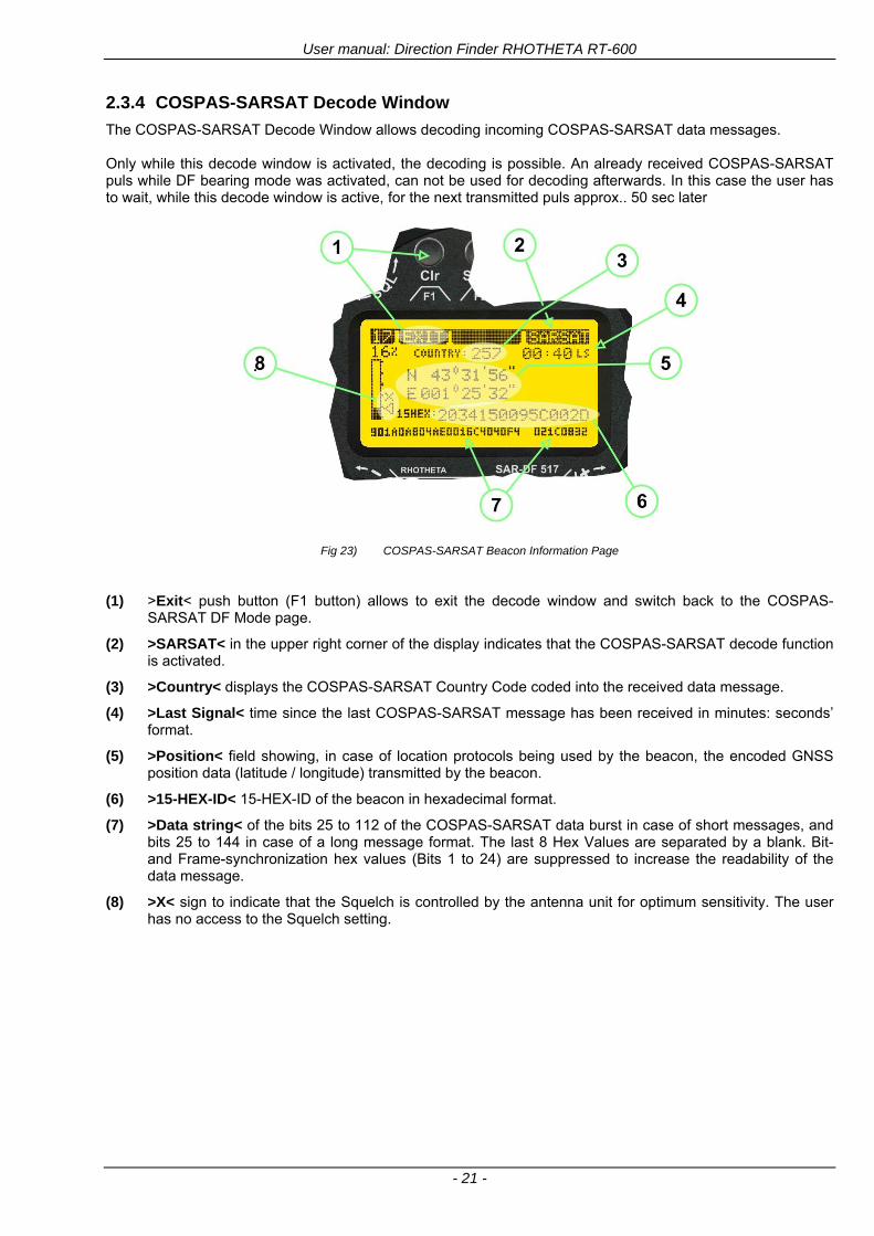
User manual Direction Finder RHOTHETA RT-600
- 21 -
234 COSPAS-SARSAT Decode Window
The COSPAS-SARSAT Decode Window allows decoding incoming COSPAS-SARSAT data messages Only while this decode window is activated the decoding is possible An already received COSPAS-SARSAT puls while DF bearing mode was activated can not be used for decoding afterwards In this case the user has to wait while this decode window is active for the next transmitted puls approx 50 sec later
Fig 23) COSPAS-SARSAT Beacon Information Page
(1) gtExitlt push button (F1 button) allows to exit the decode window and switch back to the COSPAS-
SARSAT DF Mode page
(2) gtSARSATlt in the upper right corner of the display indicates that the COSPAS-SARSAT decode function is activated
(3) gtCountrylt displays the COSPAS-SARSAT Country Code coded into the received data message
(4) gtLast Signallt time since the last COSPAS-SARSAT message has been received in minutes secondsrsquo format
(5) gtPositionlt field showing in case of location protocols being used by the beacon the encoded GNSS position data (latitude longitude) transmitted by the beacon
(6) gt15-HEX-IDlt 15-HEX-ID of the beacon in hexadecimal format
(7) gtData stringlt of the bits 25 to 112 of the COSPAS-SARSAT data burst in case of short messages and bits 25 to 144 in case of a long message format The last 8 Hex Values are separated by a blank Bit- and Frame-synchronization hex values (Bits 1 to 24) are suppressed to increase the readability of the data message
(8) gtXlt sign to indicate that the Squelch is controlled by the antenna unit for optimum sensitivity The user has no access to the Squelch setting
User manual Direction Finder RHOTHETA RT-600
- 22 -
235 Tracking 121500 MHz while in COSPAS-SARSAT Mode
While in COSPAS-SARSAT DF Mode the user can switch to 121500 MHz in order to track the beacon in VHF If a valid signal is not received in 121500 MHz the user can switch back to the last active COSPAS-SARSAT channel (406 MHz frequency) being tracking previously
Fig 24) Tracking 121500 MHz while in COSPAS-SARSAT Mode
Differences are (1) gt406xlt press F1 to switch back to the last
COSPAS-SARSAT channel (406 MHz frequency) being tracking previously
(2) gt121500 MHzlt Actual frequency being tracked
User manual Direction Finder RHOTHETA RT-600
- 23 -
236 COSPAS-SARSAT Scan Mode
If the COSPAS-SARSAT Scan Mode has been selected at the frequency selection page ldquoFRQrdquo the COSPAS-SARSAT channels as selectable manually from the Frequency Selection Page are scanned After reception of a COSPAS-SARSAT Signal the scanning is stopped at the received frequency Due to the fast scanning ndash the complete COSPAS-SARSAT sub-band is scanned within less than 400 ms ndash detection of a receivable COSPAS-SARSAT signal is possible within one COSPAS-SARSAT repetition cycle
Fig 25) FRQ Selection Page with SCN COSPAS-SARSAT Scan Page selected
At the frequency selection page an active COSPAS SARSAT scanning can be stopped by de-activating it with the rotary button (1) While the scanning is active it is also possible by pressing gtF1lt ldquoEXITrdquo to switch back to the DF pagehellip
Fig 26) DF page with active COSPAS-SARSAT Scan Mode at the DF page
(1) gtSCANlt flashing indication notifying the user that the equipment is operating in scan mode
(2) Frequency display indicating the COSPAS-SARSAT scanning frequency range
(3) gtXlt sign showing that squelch settings are controlled autonomously by the receiver
Scan mode can be left by pressing gtF1lt ldquoSTOPrdquo
User manual Direction Finder RHOTHETA RT-600
- 24 -
237 Marine Ship Scan Mode
Fig 27) DF Mode FRQ = 156800 MHz F1 for scan function
If the active frequency (2) is within the VHF Marine Band a fast scan of all ship channels is possible by pushing gtF1lt ldquoSCAN (1) In this scanning mode all marine channels 1 to 88 (156025 to 157450 MHz) are scanned continuously until a signal is received To offer the best monitoring functionality for the user also signals between to channels (4) are detected (scanning without gap) In order to prevent the scan to stop on noisy frequencies it is recommended to start scanning with high squelch settings You can reduce the squelch level in steps until the scan stops on a noisy frequency for the first time Then increase the squelch level slightly This will result in the highest possible scan sensitivity and avoiding noisy channels due to RF disturbances sometimes generated by other equipment in own aircraft
Fig 28) DF Mode active scanning in process
The scanning is stopped by pressing gtF1lt ldquoSTOPrdquo (3)
User manual Direction Finder RHOTHETA RT-600
- 25 -
24 Law Enforcement Operation Law enforcement special ops and other organizations use the RT-600 LE (LAW ENFORCEMENT) version instead of the RT-600 A (STANDARD) version One of the reasons is that the LE version features scanning and tracking of signals like LoJack and ETS as well as signals in the 216000 MHz ndash 220000 MHz band such as medical beacons wristankle transmitters cashasset recovery ldquotagsrdquo etc However the LE version shares many functions in common with the A version such as scanning and tracking in the AIR band COSPAS-SARSAT band etc
241 Power-On procedure
The power-on procedure is the same as described in 211
(1) System Version ldquo(L)rdquo for LAW ENFORCEMENT version
Fig 29) STARTUP Screen (see 211 for details)
242 LoJack Scan Mode Start scanning for a VLU Code
For the convenience of Law Enforcement and other special ops users who frequently engage in tracking SVRS (Stolen Vehicle Recovery System) signals such as LoJack (LoJack Corp FCC 9020 Part 2 SVRS) RHOTHETA has optimized the power-on procedure of the RT-600 LE version so that right after the STARTUP screen the unit displays automatically the LoJack Scan Mode page to start immediately scanning for a valid VLU (Vehicle Location Unit) code without pressing any key
Fig 30) LoJack Scan Mode unit is scanning for a LoJack VLU Code
(1) gtscan LoJacklt DF is scanning for any new LoJack VLU Code
(2) gtEXITlt press F1 to exit and switch directly to DF Mode
User manual Direction Finder RHOTHETA RT-600
- 26 -
243 LoJack Scan Mode from any other page
While operating on any page other than the LoJack Scan page the user can switch directly to LoJack Scan Mode by pressing Hotkey F2 for 2 secs
(1) press Hotkey F2 for 2 secs to switch to the LoJack Scan page
Fig 31) Hotkey F2
User manual Direction Finder RHOTHETA RT-600
- 27 -
244 Manual activation of LoJack Scan Mode
(1) select the LoJack frequency (see also Frequency Selection Page)
(2) press F1 to switch back to the DF MODE
Fig 32) FRQ Selection Page FRQ = LoJack BAND = LoJack (164-174 MHz)
While in DF MODE with adjusted LoJack frequency the user can switch directly to the LoJack Scan by pressing gtF1lt ldquoSCANrdquo
(1) press F1 SCAN to switch to the LoJack Scan page
(2) still no LoJack ID filter used (ID=off) all transmissions are received on the active frequency as example also unwanted tower pulses
Fig 33) DF Mode with LoJack filter OFF
User manual Direction Finder RHOTHETA RT-600
- 28 -
245 Receiving and accepting a new VLU Code
While in LoJack Scan Mode waiting for a VLU Code if a new VLU Code is displayed the user can accept it and switch directly to DF Mode by pressing F2
(1) a new LoJack VLU Code (0001A) has been received
(2) press F2 to accept the new VLU Code (0001A) and switch to DF MODE page with the LoJack filter activated to track only 0001A
Fig 34) LoJack Scan Mode with new VLU Code received
246 Entering a new VLU Code manually
While in LoJack Scan Mode the user can enter a LoJack VLU code also manually
(1 2 3) use the SELECTplusmn and plusmnVALUE knobs to enter a new LoJack VLU Code active ID (0001A)
(4) Press F1 to accept the new VLU Code and switch to DF Mode with the LoJack filter ON to track only 0001A
Fig 35) LoJack Scan Mode with new VLU Code entered manually
User manual Direction Finder RHOTHETA RT-600
- 29 -
247 Tracking one VLU Code while monitoring new VLU Codes
While on DF Mode and tracking a VLU Code (0001A) the user can turn the LoJack switch OFF with F2 also the user can start scanning all VLUs again with F1
0001A is displayed as the active VLU Code filter function is ON only 0001A is tracked
Monitoring of other VLU Codes is active in the background
(1) Press F1 to switch to the LoJack Scan Mode to scan for new VLU Codes
(2) Press F2 to switch LoJack filter OFF
Fig 36) DF Mode with active VLU Code and LoJack filter ON
248 Tracking one VLU Code and receiving a new VLU Code
While on DF MODE page and tracking VLU Code (0001A) in the background a new VLU Code is received and decoded (G2HC7)
(1) The new VLU Code is announced (NEW G2HC7)
(2) Press F1 to switch to LoJack Scan Mode to see the arrival time of G2HC7 and the possibility to change bearing to this new G2HC7
Fig 37) DF Mode with active VLU Code and announcement of new VLU Code
User manual Direction Finder RHOTHETA RT-600
- 30 -
249 Switching to a new VLU Code
While on the LoJack Scan Page tracking one VLU Code (0001A) and notified of a new VLU Code (G2HC7)
(1) press F1 to continue tracking 0001A
(2) press F2 to start tracking G2HC7
(3) Time elapsed since G2HC7 was last received
(4) Time elapsed since 0001A was last received
If F1 is pressed for 2 sec the indicated VLU Code (G2HC7) and ID (0001A) are deleted
Fig 38) LoJack Scan Page with one active VLU Code and one new VLU Code
2410 ldquoBlockingrdquo function of one LoJack VLU Code
The LoJack scan page can also be used to ldquoblockrdquo one unwanted LoJack VLU ID signal by separating the adjusted active ID from any other received LoJack VLU signal This is done by muting the audio (see example below) when a LoJack signal with VLU code ldquo0001Ardquo is received gtgt Any new VLU Code (active LoJack signal) - except for 0001A ndash will be displayed on the top row and generate the audible beep tone
Fig 39) LoJack Scan Page with one active VLU Code and audio OFF
Tip ldquoBlockingrdquo is an important tool for practical missions As example a stolen vehicle with VLU ID ldquo0001Ardquo was tracked in the DF bearing mode The mission
is completed but the VLU is normally still transmitting With the settings above only new VLU signals except the now unwanted ldquo0001Ardquo are audible and displayed in the upper (scan LoJack hellip for new VLU) box
User manual Direction Finder RHOTHETA RT-600
- 31 -
2411 Tracking in the 216 to 220 MHz band
The RT-600 features scanning and bearing functionality in the 216000 MHz to 220000 MHz band The 216000 MHz ndash 220000 MHz band contains frequencies and signals used by special services and tracked by law enforcement special ops and similar organizations These are some of the frequencies and services in this band
CFR 90259 tx 216000 MHz to 220000 MHz
Low Power Radio Service (LPRS) tx 216000 MHz to 217000 MHz
Medical beacons Project Lifesaver tx wristankle tx 213000 MHz to 216000 MHz
ETS tx stolen cashasset recovery tx ldquobaitrdquordquotagrdquo tx 216000 MHz to 220000 MHz tx = transmitter(s) However any future or current user of the Rhotheta RT-600 must be aware that tracking signals on the frequencies listed above may be challenging and even frustrating due mostly to negative factors in some of the transmitters
bull Very low RF power output
bull Inefficient antennas
bull Battery-powered devices with a ldquolow batteryrdquo condition
bull Devices worn or located in conditions of poor RF propagation
bull Devices with channel spacing different than the one specified for the RT-600
These factors can make it very difficult for the DF to receive the signal andor display an accurate bearing Disclaimer For the reasons explained above and even though the RT-600 features top performance in its class RHOTHETA does not offer - and is not to be held responsible for - any guaranteed minimum range or distance to a transmitter in this band
25 Setup Edit Page System settings are displayed in the setup page The functions described in this section should be used by trained personal only
Fig 40) Accessing the Setup Page
The setup page can be accessed by holding down the gtCLRlt (1) and gtREPlt (2) buttons simultaneously and in the same time performing a left-hand turn on the gtPagelt rotary switch (3)
User manual Direction Finder RHOTHETA RT-600
- 32 -
Fig 41) Setup Page
(1) gtStorelt push-button must be pressed in parallel if a value of a setting shall be modified If a value can
be modified the background stops to blink
(2) gtSelectlt rotary switch used to scroll through the menu options The value of the actually activated menu option is high-lighted with dark background and blinking
(3) gtValuelt rotary switch used to change values in menu options (gtStorelt (1) has to be pressed in parallel if a value shall be modified)
(4) gtSN-Ratiolt menu option representing the necessary Signal-To-Noise-Ratio (Difference between signal and noise level) used as criterion for the automatic squelch function Please refer to the chapter ldquoSquelch Operationrdquo for details Default value is 60 dB
(5) gtMounting Positionlt menu option to select Top- or Bottom-Mounting of the DF antenna In case of rooftop installation (eg on land vehicles) ldquoToprdquo shall be selected In case of bottom-down (upside-down) installation (eg on a helicopter) ldquoBotrdquo shall be selected If this option is not selected correctly all bearing values will be mirror-inverted
(6) gtBearing Offsetlt menu option to include a constant offset correction to the bearing indication Bearing values in degrees will be changed according to the offset value
(7) gtMaximum External Dimming Voltage for Legendslt menu option which sets the upper limit of the dimming input voltage for the legends-panel Range=[15 hellip 28]V
(8) gtMinimum External Dimming Voltage for Legendslt menu option which sets the lower limit of the dimming input voltage for the legends-panel Range=[15 hellip 28]V
(9) gtPagelt rotary switch to be turned right-hand to go back to the Direction Finder page A left-hand turn on this rotary switch will show up an additional service page with debug information used for system checks
(10) gtExtended Seriallt It is possible to enable or disable the extended serial data protocol Only of interest if serial data is used by any connected control units like moving maps or computers For detailed information see (Serial interface data protocol (short description)gt at page 46) If there are compatibility problems with already existing older remote control software it is recommended to switch OFF the extended serial data protocol
User manual Direction Finder RHOTHETA RT-600
- 33 -
3 Error messages If an internal error of the device is recognized a corresponding flashing error message will be shown in the DF pages
Fig 42) Error Messages
(1) Error message including error code (in brackets)
(2) Short description of the indicated error
In case of coincidence of various errors the error with the highest priority will be displayed
Error message Error location Reason
Error (12) VOLTDU
Main voltage supply Main Voltage input too low ( 100 V)
Error (11) NO AU
Connection antenna display or Antenna Unit
No serial data (RS485) from Antenna Unit No or damaged connection between antenna and display or damaged antenna unit
Error (10) BAD AU
Connection antenna display
Incompatibility or bad data connection between display and antenna
Error (9) BAD RU
Remote Unit Incompatibility or bad data connection between display and external serial Remote Unit or PC
Error (8) VOLTAU
Antenna Unit Voltage supply at Antenna Unit too low ( 90 V) Main voltage supply too low or considerable drop of voltage between display and antenna
Error (7) BAD DCU
Connection Display Antenna
Incompatibility or bad data connection between antenna and display
Error (6) NO DCU
Connection Display Antenna
No serial data from Display Control Unit to Antenna Unit
Error (5) PLL ERR
antenna Error in synthesizer-oscillator of receiver in Antenna Unit
Error (4) FRQ+OFS
received transmitter Received frequency too high (more than 6 KHz error of transmitter)
Error (3) FRQ-OFS
received transmitter received frequency too low (more than 6 KHZ error of transmitter)
Error (2) DECODE
radio distance transmitter DF
Data Bits of decoded signal (COSPAS-SARSAT or LoJack) defective
Error (1) DATARNG
Incompatibility of data DCU AU
Protocol data bytes out of valid range
Error (0) NO REC
Antenna Unit receiver
Receiver board defective
User manual Direction Finder RHOTHETA RT-600
- 34 -
4 Installation
41 Antenna unit A convenient position of the monopole bearing antenna is crucial for good bearing results The antenna needs an effective ground connection to the body of the aircraft or to the roof of the vehicle If there is no metallic mounting surface available a metallic sheet or similar (net) with connection to ground has to be applied first between vehicle-body and antenna In this hatched area the antenna touches the body ofthe vehicleaircraft In order to obtain a good groundconnection the surface of the body should be bared(Measuring unit [mm])
8 x holes for mounting the antenna unit to the
vehicle aircraft
Fig 43) Antenna Mounting Drawing
User manual Direction Finder RHOTHETA RT-600
- 35 -
411 Influence of antenna location and environment on the bearing accuracy
Recommendations concerning the practical antenna unit location on helicopters and airplanes
The bearing accuracy of the direction finder antenna unit is severely influenced (comparable to an airspeed sensor) by the environment For comparison a perfect high quality speed sensor will not indicate the true airspeed if this sensor is interfered by strong turbulences The direction finder antenna unit acts as a sensor for electromagnetic waves In the near field of this antenna unit any conductive (eg metallic) obstacle will influence the incoming wave field and create reflections which decrease the bearing accuracy These are general physical limitations concerning all types of direction finder systems To achieve the best bearing results it should be considered that the antenna unit is installed as far away as possible from any other vertically polarized conductive structure If possible there should be no reflectors within an area of 2-3 feet around the antenna unit In this worst case example the direction finder will not work properly
Fig 44) Antenna Installed in a Bad Location
In this example the antenna unit is located too close to the cable cutter of the helicopter This cutter will produce strong reflections especially as the length is equal to Lambda4 within the VHF airband
User manual Direction Finder RHOTHETA RT-600
- 36 -
Examples of properly installed direction finder antenna units
Fig 45) Antenna Installed in Good Locations
User manual Direction Finder RHOTHETA RT-600
- 37 -
42 Display and Control Unit
The display control unit may be mounted into a front panel by the means of this mounting drawing
Fig 46) DCU Mounting Drawing
(all dimensions in [mm]) To install or uninstall the display control unit perform the following steps (1) Remove the cover caps of the four rotary switches
(2) Loose the screws visible below the position of the cover caps
(3) Remove the plastic button from the axis of the four rotary switches
(4) Mount dismount the display control unit
(5) Re-install the plastic buttons on the axis of the four rotary switches
(6) Fix the screws so that the plastic buttons are fixed on the axis
(7) Re-install the cover caps on the four rotary switches
User manual Direction Finder RHOTHETA RT-600
- 38 -
43 System Interconnect Wiring Diagram (Also refer to chapter ldquoTechnical Datardquo for details)
Fig 47) System Interconnect Wiring Diagram
6-pol Amphenol plug femalePTG06SE10-6S(SQ)
max length of cable 20 m 9-pol Sub-D plug (femalemale)
User manual Direction Finder RHOTHETA RT-600
- 39 -
5 Technical Data
51 Electric features
Method of bearing Doppler-principle (3 kHz rotational frequency right left rotation)
Bearing accuracy1 plusmn 5deg RMS
Internal resolution 1deg
Bearing Sensitivity VHF AirEmergency le 25 μVm (typical)
VHF Marine le 25 μVm (typical)
UHF Emergency and ETS le 4 μVm (typical)
COSPAS-SARSAT le 4 μVm (typical)
LoJack Decoding (50 Message Error Rate) and bearing le 5 μVm (typical)
Frequency stability plusmn 20 ppm (Δff = plusmn210-6)
Reception frequencies
SAR version (Standard)
Frequency Options
VHF Emergency Band 118000 to 124000 MHz (833 kHz steps AM)
VHF Marine Band 154000 to 163000 MHz ( 500 kHz steps FM) (channel 16 selectable via channel no)
UHF Emergency Band 240000 to 246000 MHz (2500 kHz steps AM)
UHF FM Band 406100 to 410000 MHz ( 500 kHz steps FM)
COSPAS-SARSAT 400000 to 406092 MHz Including 406022 to 406076 MHz (Channel A S)
F1 VHF Air Band 118000 to 136992 MHz
F2 extended VHF Marine Band 137000 to 224995 MHz
F3 extended UHF Air Band 225000 to 399975 MHz
F4 additional UHF FM Band 406100 to 470000 MHz
Reception frequencies
LAW Enforcement version
Frequency Options
VHF Emergency Band 118000 to 124000 MHz (833 kHz steps AM)
VHF Marine Band 154000 to 163000 MHz (500 kHz steps FM) (channel 16 selectable via channel no)
LoJack 164000 to 174000 MHz (125 kHz steps FM)
ETS 216000 to 220000 MHz (10125 kHz AM)
COSPAS-SARSAT 400000 to 406092 MHz Including 406022 to 406076 MHz (Channel A S)
F1VHF Air Band 118000 to 136992 MHz
F2 extended VHF Marine Band 137000 to 163000 MHz
COSPAS-SARSAT fast scan mode
Full automatic detection of any active COSPAS-SARSAT channel A to S within 400 ms
COSPAS-SARSAT decoding
Reception and decoding of COSPAS-SARSAT data signal (112 or 144 bit) specified according to COSPAS-SARSAT
LoJack decoding Selectable LoJack ID display and selective active filtering
Special scanning modes
complete maritime ship band scanning within 3 s (channel 01 hellip 88 also frequencies between 2 channels are included)
1With undisturbed wave field and sufficient field strength Measuring by changing the angle of incidence with the antenna rotating on a revolving table in order to eliminate environmental influences on the results No modulation
User manual Direction Finder RHOTHETA RT-600
- 40 -
Bearable modulation A3E F3E A3X (ELT-modulation) F1D G2D COSPAS-SARSAT Bearing largely independent of modulation
Polarization Vertical
Polarization error 5deg at 60deg field vector rotation
Garbling cone Ca 30deg to the vertical
Time of response2 50 ms (with sufficient reception field strength)
LC-graphic display 128 x 64 pixels supertwist transflective extended range of temperature dark-blue display on yellow-green background background light Freely adjustable (exponential) dimming of brightness
NVG cockpit design Fully compatible NVIS Green B display Control Unit optional
Operating voltage 275 V nominal 12 V to 35 V DC
Current consumption LCD-background light Off max 500 mA (12 V DC) max 250 mA (24 V DC)
LCD-background light 100 max 750 mA (12 V DC) max 350 mA (24 V DC)
LCD-background light 100 max 900 mA (12 V DC) with NVG Option max 400 mA (24 V DC)
Audio out For external speaker approx 2 W (4 Ω)
Serial data interface Serial interface RS-232 (9600 baud 8 data bits 1 stop bit no parity)
2Very weak signals can considerably increase the time of response
User manual Direction Finder RHOTHETA RT-600
- 41 -
52 Interface External connections (optional at Sub-D 9-pol Male connector)
Dimming
Pin 8
external voltage input for variable dimming of legends
(optional)
Analog input signal for variable control of the legends illumination Input voltage range is freely adjustable in the range of 15 hellip 28 V in the setup menu Refer to chapter ldquoSetup Pagerdquo Default setting 8 hellip28 V (8 V = Off 28 V = max dimming for legends)
Input Impedance gt 50 k
Pin 6 night status line for LCD
dimming (optional)
Low-active (as example switch to ground) At input voltage lt 25 VDC the LCD dimming operates in nightNVG mode Maximum brightness ca 4 of daydefault mode brightness
Input Impedance gt 50 k
Pin 4 NVG status line for LCD
dimming (optional)
Low-active (as example switch to ground) At input voltage lt 25 VDC the LCD dimming operates in nightNVG mode Maximum brightness ca 4 of daydefault mode brightness
Input Impedance gt 50 k
AudioLF
Pin 7 Audio output signal
AC coupled voltage source with very low inner resistance Maximum output voltage ca 8 VPP = 283V RMS at maximum Volume Maximum output power ca 2 W with 4 speaker
If a headphone is connected ([32hellip600] 100mW) we recommend using a resistor (18 025 W) between audio output and headphone to prevent damage of the headphone
Serial interface RS232 (9600 baud 8 data bits 1 stop bit no parity)
Pin 3 TXD Serial output (ca plusmn10 V)
Pin 2 RXD Serial input (ca plusmn10 V)
User manual Direction Finder RHOTHETA RT-600
- 42 -
53 Mechanical features
Temperature range
Display Control Unit permissible operating temperature3 -20 degC +60 degC permissible storage temperature -30 degC +80 degC
Antenna Unit permissible operating temperature3 -40 degC +60 degC permissible storage temperature -55 degC +80 degC
Protective system Antenna Unit IP 67
Weights Display Control Unit 250 g Antenna Unit 2000 g
Dimensions Display Control Unit 82 mm x 82 mm x 43 mm (width x height x depth) Antenna Unit 270 mm x 185 mm
Fig 48) DCU Mechanical Drawing (all dimensions in [mm])
3 For temperatures lower than ndash10deg C a warm-up period of 15 min should be allowed
User manual Direction Finder RHOTHETA RT-600
- 43 -
Fig 49) AU Mechanical Drawing (all dimensions in [mm])
User manual Direction Finder RHOTHETA RT-600
- 44 -
6 Appendix
61 Frequency Ranges
User manual Direction Finder RHOTHETA RT-600
- 45 -
62 Frequencies of channels on maritime band (only for standard [A] version) Frequency-range of the RT-600 in the maritime band 156000 MHz 162025 MHz
Channel No frequency (ship - station) Frequency (coast - station)
1 156050 MHz 160650 MHz 2 156100 MHz 160700 MHz 3 156150 MHz 160750 MHz 4 156200 MHz 160800 MHz 5 156250 MHz 160850 MHz 6 156300 MHz 160900 MHz 7 156350 MHz 160950 MHz 8 156400 MHz 9 156450 MHz
10 156500 MHz 11 156550 MHz 12 156600 MHz 13 156650 MHz 14 156700 MHz 15 156750 MHz 16 156800 MHz 17 156850 MHz 18 156900 MHz 161500 MHz 19 156950 MHz 161550 MHz 20 157000 MHz 161600 MHz 21 157050 MHz 161650 MHz 22 157100 MHz 161700 MHz 23 157150 MHz 161750 MHz 24 157200 MHz 161800 MHz 25 157250 MHz 161850 MHz 26 157300 MHz 161900 MHz 27 157350 MHz 161950 MHz 28 157400 MHz 162000 MHz 60 156025 MHz 160625 MHz 61 156075 MHz 160675 MHz 62 156125 MHz 160725 MHz 63 156175 MHz 160775 MHz 64 156225 MHz 160825 MHz 65 156275 MHz 160875 MHz 66 156325 MHz 160925 MHz 67 156375 MHz 68 156425 MHz 69 156475 MHz 70 156525 MHz 71 156575 MHz 72 156625 MHz 73 156675 MHz 74 156725 MHz 75 156775 MHz 76 156825 MHz 77 156875 MHz 78 156925 MHz 161525 MHz 79 156975 MHz 161575 MHz 80 157025 MHz 161625 MHz 81 157075 MHz 161675 MHz 82 157125 MHz 161725 MHz 83 157175 MHz 161775 MHz 84 157225 MHz 161825 MHz 85 157275 MHz 161875 MHz 86 157325 MHz 161925 MHz 87 157375 MHz 161975 MHz 88 157425 MHz 162025 MHz
User manual Direction Finder RHOTHETA RT-600
- 46 -
63 Serial interface data protocol (short description)
631 General
Interface parameters RS232 9600 Baud 8 databits 1 stopbit no parity LSB sent first Timing of serial data For accurate use of the serial data (even for the optional serial input commands) the correct timing is mandatory The DCU (Display Control Unit) sends out via the RS-232 Pins (see 43 System Interconnect Wiring Diagram page 38) cyclic and autonomous every approx 250300 ms a binary data stream which contains all relevant DF-bearing information The output data contains one or two blocks of binary data (see next picture with accordingly description) The optional serial input is only used if changes (as example frequency change) are done by additional remote control units
Fig 50) Timing of serial data
Serial standard output
This output data is always available and contains all relevant DF-bearing data For detailed content see page 47
Optional extended serial output
This data contains some additional information like as example CospasSarsat or LoJack decoding and ID data For detailed content see page 50 The data is only available with DCU Software [Rev ge 320] and if this optional data block is configured as ON = enabled (see Setup Edit Page point (10) )
Even to avoid compatibility problems with already existing older remote control software it is possible to disable switch off this additional data block (see Setup Edit Page point (10) )
Optional serial input
Only used for optional commands to control DCU parameters If as example the direction finder frequency is changed remotely there is send to the DCU one time this data block with the new frequency For detailed content see page 52
User manual Direction Finder RHOTHETA RT-600
- 47 -
632 Serial standard output (protocol description)
Specification serial standard output
The binary data stream with a length of 39 bytes starts with a header byte (value = hex 0xA0 as ID for DF Mode) The next bytes contain different values for status bearing information and also service The last byte is used for data stream checksum control Remark This is a binary data protocol So every byte value from 0dec hellip 255dec (0x00 hellip 0xFF) is possible Because of this it is not allowed to realize a start byte detection by the content (0xA0) The idle line detection is recommended for detection the end of message Register of databytes (for details see next page)
byte no
[0] Header = 0xA0 Id for DF Mode
[1] Number = 39 = bytes in the complete message (including header and checksumbyte)
[2] Status (1) HSB [x|x|x|x|x|x|x|x] LSB | | | | | | | --gt (0) Receiving | | | | | | ----gt (1) Squelch controlled by AU (X) | | | | | ------gt (2) Permission RL Calibration | | | | --------gt (3) Line Night | | | ----------gt (4) Line NVG | | ------------gt (5) Dimming External | --------------gt (6) Autosquelch Active ----------------gt (7) 0=Standard Version 1=LE Version
[3] Status (2) HSB [x|x|x|x|x|x|x|x] LSB | ----------------gt (7) 0=Standard 1=extended serial dataprotocol = ONactive
[45] Error (Bits[120])
[6] Actual DCU Page
[7] Volume [0hellip100]
[811] Frequency [Hz]
[12] Active Band
[13] Actual Squelchlevel [0hellip60]
[14] Audio-Line amp_NF_Test Output
[15] (Not used)
[1617] Voltage_DCU ([0hellip335]=[0 hellip 335]V
[1819] Voltage_AU ([0hellip255]=[0 hellip 255]V
[20] Temperature_AU [-68hellip+127]degC
[21] Frequency Offset [-99hellip+99]
[2225] ServiceTest values (mode dependent test values for service only)
26 (Not used reserved)
[27] Level [0hellip100]
[2829] Bearing Averaged [0hellip359]deg relative
[3031] Bearing Live_Min [0hellip359]deg relative
[3233] Bearing Live_Max [0hellip359]deg relative
[34] Test Value PS-RAM Right Rotation[0hellip178] (for service only)
[35] Test Value PS-RAM Left Rotation [0hellip178] (for service only)
[3637] (Not used reserved)
[38] Checksum is the 2rsquos complement of the modulo-256 sum of all bytes without checksum-byte [0n-1]
User manual Direction Finder RHOTHETA RT-600
- 48 -
Detailed Description of important values for practical use
Status byte [2] Receiving Bit 0 of this value (LSB) indicates signal receiving Bit 0 = 0 then no signal is received and so on no bearing is available Bit 0 = 1 then bearing is possible Bit 1 if(1) then Squelch is controlled by AU (active at modes CospasSarsat Decode CospasSarsat Scanning LoJack with Filter=ID only)
Error bytes [4hellip5] 16 bit value each set bit corresponds to the error no (Refer to the chapter Error messages) Example - 0x0000 No error - 0x0800 Bit No 11 Set ( = No AU Error)
Actual DCU Page byte [6] indicates actual operating mode of DCU 0 = Standard bearing page 1 = Frequency memory page 2 = CospasSarsat decoding page 3 = LoJack decoding page (ID edit)
Frequency bytes [8hellip11] 32 bit value actual adjusted frequency [Hz] Example - 0x073DF160 1215000000 121500 MHz
Active Band Standard Version [A] 0=VHF Airband 1=VHF Marineband sea 2=VHF Marineband coast 3=UHV Airband 4=CospasSarsat LE Version [L] 0=VHF Airband 1=LoJack 2=Lifesaver 3=ETS 4=CospasSarsat
Actual Squelchlevel byte [13] Range [0hellip60] without signal the actual squelchlevel should always be adjusted a little bit over the noise level (Refer to the chapter Squelch operation)
Level byte [27] Range [099] actual receiving level (without signal this value is equal to the noise level) If a signal is received then this value corresponds to the signal strength of this signal
Relative Bearing averaged byte [2829] 16 bit value Range [0hellip359 0xFFFF] if the value = 0xFFFF then no valid bearing is available otherwise this value contains the actual averaged bearing information in Deg [0deg359deg] Example - 0X0114 276deg bearing (= left side oriented to heading)
Bearing Live MinMax byte[3031] amp [3233] - 16 bit values Range [0hellip359 0xFFFF] Only for signal quality or additional information ndash NOT recommended for bearing indication The relative live bearing field contains the maxmin bearing in degrees without averaging The relative live bearing reacts faster than the normal relative bearing but it has not the precision of the averaged bearing The MinMax Bearing Values are calculated within a time period of approx 250 ms If they are very close together (for example ldquo124rdquo and ldquo128rdquo degrees) then the signal quality is quite good A wide span of the minmax values (for example ldquo97rdquo and ldquo162rdquo) shows very noisy but nevertheless bearable signal quality
User manual Direction Finder RHOTHETA RT-600
- 49 -
633 DCU Info output (protocol description)
Specification DCU Info output
Remark This protocol is only available while the SetupEdit page is activated at the DCU
byte no
[0] Header = 0xAF Id for DCU Info Mode
[1] Number = 39 = bytes in the complete message (including header and checksumbyte)
[2]
(see standard output) [3]
[45]
[621] Info String of 15 byteschars the string contains Information about Unit Variant Software Version and Serial No
Example Byte [318] =
|--AU ID---||Var-||---Software Version---| |-------------- Serial No---------------| [0x44][0x55][0x41][0x33][0x2E][0x33][0x30][0x3A][0x20][0x20][0x30][0x31][0x32][0x33][0x34][0x00] rsquoDrsquo rsquoUrsquo rsquoArsquo rsquo3rsquo rsquorsquo rsquo3rsquo rsquo0rsquo rsquorsquo rsquo rsquo rsquo rsquo rsquo0rsquo rsquo1rsquo rsquo2rsquo rsquo3rsquo rsquo4rsquo rsquoENDrsquo | | | | __________________ | | ________________________ | n n n | | n n n n n | (Software Version) | | (Serial No) | gt rsquoArsquo = Standard Variant gt rsquoLrsquo = Law Enforcement Variant
User manual Direction Finder RHOTHETA RT-600
- 50 -
634 Optional extended serial output (protocol description)
The data content depends on the actual mode of the direction finder To get special data the direction finder has first to be switched to the equivalent mode
COSPAS-SARSAT Decoding data
This data is only available and valid if Display Control Unit with actual software Rev ge 320 (see Power-On procedure page 10) Configuration of Extended serial = ON (see Setup Edit Page point (10) ) Direction Finder COSPAS-SARSAT decoding mode is activated by selecting the corresponding page
(see COSPAS-SARSAT Decode Window page 20 and page 21) and so on Header (byte 0 of data) = 0x91
A valid COSPAS-SARSAT decoding data protocol is always marked by the first data byte (header = 0x91) Always after receiving and decoding of a valid COSPAS-SARSAT pulse the complete data protocol with 33 bytes is send out one time
Byte No
[0] Header = 0x91 (Identification for CPSarsat decoding mode)
[1] Number of bytes - 7 if no decoded pulse is available - 33 if new pulse was received and is available
[2] Error
[3] Bit[0] - 0 =gt No new 406 MSG (decoded data) available - 1 =gt New valid 406 MSG available (Sync amp Frame Ok) Check Error Status for Bit-Errors
Bit[61] AutoSquelch Level valid range [060] ( decimal)
Bit[7] = 1 Squelch controlled by AU
[4] Signallevel of received signal valid range [099] ( decimal)
[5] Voltage of Antenna Unit Power Supply input valid range [80255] (decimal = 80 255 V DC)
[6] Temperature inside Antenna Unit valid range [-50+100] (degC signed byte value)
The following databytes are only available if a correct CPSarsat puls gets received and decoded with correct checksum
[724] 18 x Databytes complete orginal CPSarsat 406 decoded message (144 bit)
Databyte Nr [ Byte 7 ] [ Byte 8 ] [Byte9 Byte24] 406 MSG Bit Nr [1 2 3 4 5 6 7 8] [9 10 11 12 13 14 15 16] [17 144]
[25] SN-Flag valid values 0x53=rsquoSrsquo 0x4E=rsquoNrsquo 0x2D=rsquo-rsquo if no GPS data available
GPS-Position Latitude
[26] Deg valid values [090] (decimal Deg) 0xFF if no GPS data available
[27] Min valid values [059] (decimal Deg) 0xFF if no GPS data available
[28] Sec valid values [059] (decimal Deg) 0xFF if no GPS data available
[29] WE-Flag valid values 0x57=rsquoWrsquo 0x45=rsquoErsquo 0x2D=rsquo-rsquo if no GPS data available
GPS-Position Longitude
[30] Deg valid values [0180] (decimal Deg) 0xFF if no GPS data available
[31] Min valid values [059] (decimal Deg) 0xFF if no GPS data available
[32] Sec valid values [059] (decimal Deg) 0xFF if no GPS data available
User manual Direction Finder RHOTHETA RT-600
- 51 -
LoJack ID data
This data is only available and valid if Display Control Unit with actual software Rev ge 320 (see Power-On procedure page 10) Direction Finder of variant [L] Law Enforcement Configuration of Extended serial = ON (see Setup Edit Page point (10) ) Direction Finder is working with active LoJack gtID Filterlt Header (byte 0 of data) = 0x93 or 0x94
Valid LoJack ID decoding data is always marked by the first data byte (header = 0x93 or 0x94)
Byte No
[0] Header = 0x93 LoJack ID editing sub-page is selected Filter = VLU all valid and received LoJack pulses are indicated = 0x94 Lojack Decode amp DF Mode with active Filter = ID
[1] Number of bytes in the complete data stream - decimal 26 = default value
[2] Nonrelevant
[3] Bit[0] Receiving OnOff - 0 =gt No Receiving no bearing - 1 =gt new LoJack pulse received
[412] Nonrelevant
[1317] Lojack ID
Replay Code 5 x ASCII Chars ldquoNo BIOZrdquo set
Example ASCII = ldquo000R1rdquo
18 Receiver Level Out Max [099]
19
LoJack Decoder Status [07] - 0 Off - 1 Wait for Preamble - 2 Preamble Ok - 3 FlagPattern Ok - 4 Data BitError gt 1 - 5 Data Ok (No VLU) - 6 VLU Ok - 7 ID Ok (Filter=IDONLY)
[2025] Nonrelevant
Remark Only if byte no [3] bit [0] gets ldquo1rdquo (Receiving On) then an active LoJack pulse is received and so on the corresponding LoJack ID valid otherwise the LoJack ID only shows the actual adjusted LoJack Filter ID of the direction finder
User manual Direction Finder RHOTHETA RT-600
- 52 -
635 Optional serial input (protocol description)
Specification serial input (optional)
The serial input is normally used for service and maintenance only Nevertheless it is possible via this interface to remote control the actual frequency and the squelchlevel of the DF system If a valid data stream is send to the DF then the actual frequency selection at the DCU is switched to Block2 AUX0 At this memory channel the new frequency is stored and used automatically (Refer to the chapter Frequency Selection Page) If the frequency is changed (by one valid data stream) no more serial input is necessary The actual frequency can be changed again at any time by manual operation at the DCU The timing of serial input (if used) is strictly fixed The optional serial input has to take place directly after a complete serial output (max 50 ms delay time) If a new changed frequency is commanded to the DCU via this serial input interface it can take up to 1 sec of time until this new frequency is ready for operationbearing It is strictly not recommended to use the frequency remote control for any scan mode The frequency control has to be used for static frequency change only Register of databytes
byte no
[0] Header 0xC0
[1] Number of bytes in the complete message (including header and checksumbyte)
[23] (not used for normal operation any byte values allowed)
[4] Volume [0100]
[58] Frequency [Hz] (frequency is rounded to the according grid automatically)
Valid Range for Standard Version Valid Range for LE Version
118000000 hellip 123000000 [Hz] 8333 kHz 118000000 hellip 123000000 [Hz] 8333 kHz
156050000 hellip 162025000 [Hz] 5000 kHz 164000000 hellip 174000000 [Hz] 8333 kHz
201000000 hellip 215995000 [Hz] 5000 kHz
240000000 hellip 246000000 [Hz] 8333 kHz 216000000 hellip 218995000 [Hz] 12500 kHz219000000 hellip 220000000 [Hz] 10000 kHz
400000000 hellip 410000000 [Hz] 8333 kHz 400000000 hellip 410000000 [Hz] 8333 kHz
[9] Squelchlevel Manual = [0hellip60] Autosql= [ -1] Warning use only for pulsed signals (as example CpSarsat LoJack)
[10] (not used for normal operation any byte values allowed)
[11] Internal Dimming [0100]
[12] Checksum is the 2rsquos complement of the modulo-256 sum of all bytes without checksum-byte [0n-1]
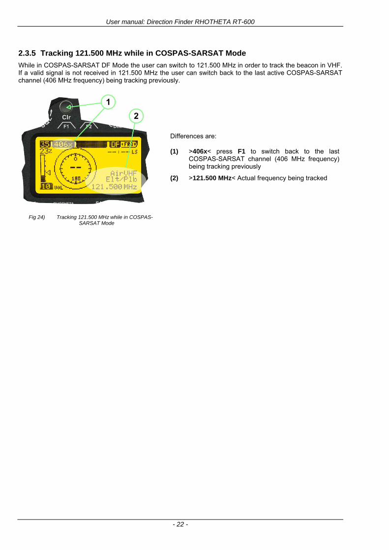
User manual Direction Finder RHOTHETA RT-600
- 22 -
235 Tracking 121500 MHz while in COSPAS-SARSAT Mode
While in COSPAS-SARSAT DF Mode the user can switch to 121500 MHz in order to track the beacon in VHF If a valid signal is not received in 121500 MHz the user can switch back to the last active COSPAS-SARSAT channel (406 MHz frequency) being tracking previously
Fig 24) Tracking 121500 MHz while in COSPAS-SARSAT Mode
Differences are (1) gt406xlt press F1 to switch back to the last
COSPAS-SARSAT channel (406 MHz frequency) being tracking previously
(2) gt121500 MHzlt Actual frequency being tracked
User manual Direction Finder RHOTHETA RT-600
- 23 -
236 COSPAS-SARSAT Scan Mode
If the COSPAS-SARSAT Scan Mode has been selected at the frequency selection page ldquoFRQrdquo the COSPAS-SARSAT channels as selectable manually from the Frequency Selection Page are scanned After reception of a COSPAS-SARSAT Signal the scanning is stopped at the received frequency Due to the fast scanning ndash the complete COSPAS-SARSAT sub-band is scanned within less than 400 ms ndash detection of a receivable COSPAS-SARSAT signal is possible within one COSPAS-SARSAT repetition cycle
Fig 25) FRQ Selection Page with SCN COSPAS-SARSAT Scan Page selected
At the frequency selection page an active COSPAS SARSAT scanning can be stopped by de-activating it with the rotary button (1) While the scanning is active it is also possible by pressing gtF1lt ldquoEXITrdquo to switch back to the DF pagehellip
Fig 26) DF page with active COSPAS-SARSAT Scan Mode at the DF page
(1) gtSCANlt flashing indication notifying the user that the equipment is operating in scan mode
(2) Frequency display indicating the COSPAS-SARSAT scanning frequency range
(3) gtXlt sign showing that squelch settings are controlled autonomously by the receiver
Scan mode can be left by pressing gtF1lt ldquoSTOPrdquo
User manual Direction Finder RHOTHETA RT-600
- 24 -
237 Marine Ship Scan Mode
Fig 27) DF Mode FRQ = 156800 MHz F1 for scan function
If the active frequency (2) is within the VHF Marine Band a fast scan of all ship channels is possible by pushing gtF1lt ldquoSCAN (1) In this scanning mode all marine channels 1 to 88 (156025 to 157450 MHz) are scanned continuously until a signal is received To offer the best monitoring functionality for the user also signals between to channels (4) are detected (scanning without gap) In order to prevent the scan to stop on noisy frequencies it is recommended to start scanning with high squelch settings You can reduce the squelch level in steps until the scan stops on a noisy frequency for the first time Then increase the squelch level slightly This will result in the highest possible scan sensitivity and avoiding noisy channels due to RF disturbances sometimes generated by other equipment in own aircraft
Fig 28) DF Mode active scanning in process
The scanning is stopped by pressing gtF1lt ldquoSTOPrdquo (3)
User manual Direction Finder RHOTHETA RT-600
- 25 -
24 Law Enforcement Operation Law enforcement special ops and other organizations use the RT-600 LE (LAW ENFORCEMENT) version instead of the RT-600 A (STANDARD) version One of the reasons is that the LE version features scanning and tracking of signals like LoJack and ETS as well as signals in the 216000 MHz ndash 220000 MHz band such as medical beacons wristankle transmitters cashasset recovery ldquotagsrdquo etc However the LE version shares many functions in common with the A version such as scanning and tracking in the AIR band COSPAS-SARSAT band etc
241 Power-On procedure
The power-on procedure is the same as described in 211
(1) System Version ldquo(L)rdquo for LAW ENFORCEMENT version
Fig 29) STARTUP Screen (see 211 for details)
242 LoJack Scan Mode Start scanning for a VLU Code
For the convenience of Law Enforcement and other special ops users who frequently engage in tracking SVRS (Stolen Vehicle Recovery System) signals such as LoJack (LoJack Corp FCC 9020 Part 2 SVRS) RHOTHETA has optimized the power-on procedure of the RT-600 LE version so that right after the STARTUP screen the unit displays automatically the LoJack Scan Mode page to start immediately scanning for a valid VLU (Vehicle Location Unit) code without pressing any key
Fig 30) LoJack Scan Mode unit is scanning for a LoJack VLU Code
(1) gtscan LoJacklt DF is scanning for any new LoJack VLU Code
(2) gtEXITlt press F1 to exit and switch directly to DF Mode
User manual Direction Finder RHOTHETA RT-600
- 26 -
243 LoJack Scan Mode from any other page
While operating on any page other than the LoJack Scan page the user can switch directly to LoJack Scan Mode by pressing Hotkey F2 for 2 secs
(1) press Hotkey F2 for 2 secs to switch to the LoJack Scan page
Fig 31) Hotkey F2
User manual Direction Finder RHOTHETA RT-600
- 27 -
244 Manual activation of LoJack Scan Mode
(1) select the LoJack frequency (see also Frequency Selection Page)
(2) press F1 to switch back to the DF MODE
Fig 32) FRQ Selection Page FRQ = LoJack BAND = LoJack (164-174 MHz)
While in DF MODE with adjusted LoJack frequency the user can switch directly to the LoJack Scan by pressing gtF1lt ldquoSCANrdquo
(1) press F1 SCAN to switch to the LoJack Scan page
(2) still no LoJack ID filter used (ID=off) all transmissions are received on the active frequency as example also unwanted tower pulses
Fig 33) DF Mode with LoJack filter OFF
User manual Direction Finder RHOTHETA RT-600
- 28 -
245 Receiving and accepting a new VLU Code
While in LoJack Scan Mode waiting for a VLU Code if a new VLU Code is displayed the user can accept it and switch directly to DF Mode by pressing F2
(1) a new LoJack VLU Code (0001A) has been received
(2) press F2 to accept the new VLU Code (0001A) and switch to DF MODE page with the LoJack filter activated to track only 0001A
Fig 34) LoJack Scan Mode with new VLU Code received
246 Entering a new VLU Code manually
While in LoJack Scan Mode the user can enter a LoJack VLU code also manually
(1 2 3) use the SELECTplusmn and plusmnVALUE knobs to enter a new LoJack VLU Code active ID (0001A)
(4) Press F1 to accept the new VLU Code and switch to DF Mode with the LoJack filter ON to track only 0001A
Fig 35) LoJack Scan Mode with new VLU Code entered manually
User manual Direction Finder RHOTHETA RT-600
- 29 -
247 Tracking one VLU Code while monitoring new VLU Codes
While on DF Mode and tracking a VLU Code (0001A) the user can turn the LoJack switch OFF with F2 also the user can start scanning all VLUs again with F1
0001A is displayed as the active VLU Code filter function is ON only 0001A is tracked
Monitoring of other VLU Codes is active in the background
(1) Press F1 to switch to the LoJack Scan Mode to scan for new VLU Codes
(2) Press F2 to switch LoJack filter OFF
Fig 36) DF Mode with active VLU Code and LoJack filter ON
248 Tracking one VLU Code and receiving a new VLU Code
While on DF MODE page and tracking VLU Code (0001A) in the background a new VLU Code is received and decoded (G2HC7)
(1) The new VLU Code is announced (NEW G2HC7)
(2) Press F1 to switch to LoJack Scan Mode to see the arrival time of G2HC7 and the possibility to change bearing to this new G2HC7
Fig 37) DF Mode with active VLU Code and announcement of new VLU Code
User manual Direction Finder RHOTHETA RT-600
- 30 -
249 Switching to a new VLU Code
While on the LoJack Scan Page tracking one VLU Code (0001A) and notified of a new VLU Code (G2HC7)
(1) press F1 to continue tracking 0001A
(2) press F2 to start tracking G2HC7
(3) Time elapsed since G2HC7 was last received
(4) Time elapsed since 0001A was last received
If F1 is pressed for 2 sec the indicated VLU Code (G2HC7) and ID (0001A) are deleted
Fig 38) LoJack Scan Page with one active VLU Code and one new VLU Code
2410 ldquoBlockingrdquo function of one LoJack VLU Code
The LoJack scan page can also be used to ldquoblockrdquo one unwanted LoJack VLU ID signal by separating the adjusted active ID from any other received LoJack VLU signal This is done by muting the audio (see example below) when a LoJack signal with VLU code ldquo0001Ardquo is received gtgt Any new VLU Code (active LoJack signal) - except for 0001A ndash will be displayed on the top row and generate the audible beep tone
Fig 39) LoJack Scan Page with one active VLU Code and audio OFF
Tip ldquoBlockingrdquo is an important tool for practical missions As example a stolen vehicle with VLU ID ldquo0001Ardquo was tracked in the DF bearing mode The mission
is completed but the VLU is normally still transmitting With the settings above only new VLU signals except the now unwanted ldquo0001Ardquo are audible and displayed in the upper (scan LoJack hellip for new VLU) box
User manual Direction Finder RHOTHETA RT-600
- 31 -
2411 Tracking in the 216 to 220 MHz band
The RT-600 features scanning and bearing functionality in the 216000 MHz to 220000 MHz band The 216000 MHz ndash 220000 MHz band contains frequencies and signals used by special services and tracked by law enforcement special ops and similar organizations These are some of the frequencies and services in this band
CFR 90259 tx 216000 MHz to 220000 MHz
Low Power Radio Service (LPRS) tx 216000 MHz to 217000 MHz
Medical beacons Project Lifesaver tx wristankle tx 213000 MHz to 216000 MHz
ETS tx stolen cashasset recovery tx ldquobaitrdquordquotagrdquo tx 216000 MHz to 220000 MHz tx = transmitter(s) However any future or current user of the Rhotheta RT-600 must be aware that tracking signals on the frequencies listed above may be challenging and even frustrating due mostly to negative factors in some of the transmitters
bull Very low RF power output
bull Inefficient antennas
bull Battery-powered devices with a ldquolow batteryrdquo condition
bull Devices worn or located in conditions of poor RF propagation
bull Devices with channel spacing different than the one specified for the RT-600
These factors can make it very difficult for the DF to receive the signal andor display an accurate bearing Disclaimer For the reasons explained above and even though the RT-600 features top performance in its class RHOTHETA does not offer - and is not to be held responsible for - any guaranteed minimum range or distance to a transmitter in this band
25 Setup Edit Page System settings are displayed in the setup page The functions described in this section should be used by trained personal only
Fig 40) Accessing the Setup Page
The setup page can be accessed by holding down the gtCLRlt (1) and gtREPlt (2) buttons simultaneously and in the same time performing a left-hand turn on the gtPagelt rotary switch (3)
User manual Direction Finder RHOTHETA RT-600
- 32 -
Fig 41) Setup Page
(1) gtStorelt push-button must be pressed in parallel if a value of a setting shall be modified If a value can
be modified the background stops to blink
(2) gtSelectlt rotary switch used to scroll through the menu options The value of the actually activated menu option is high-lighted with dark background and blinking
(3) gtValuelt rotary switch used to change values in menu options (gtStorelt (1) has to be pressed in parallel if a value shall be modified)
(4) gtSN-Ratiolt menu option representing the necessary Signal-To-Noise-Ratio (Difference between signal and noise level) used as criterion for the automatic squelch function Please refer to the chapter ldquoSquelch Operationrdquo for details Default value is 60 dB
(5) gtMounting Positionlt menu option to select Top- or Bottom-Mounting of the DF antenna In case of rooftop installation (eg on land vehicles) ldquoToprdquo shall be selected In case of bottom-down (upside-down) installation (eg on a helicopter) ldquoBotrdquo shall be selected If this option is not selected correctly all bearing values will be mirror-inverted
(6) gtBearing Offsetlt menu option to include a constant offset correction to the bearing indication Bearing values in degrees will be changed according to the offset value
(7) gtMaximum External Dimming Voltage for Legendslt menu option which sets the upper limit of the dimming input voltage for the legends-panel Range=[15 hellip 28]V
(8) gtMinimum External Dimming Voltage for Legendslt menu option which sets the lower limit of the dimming input voltage for the legends-panel Range=[15 hellip 28]V
(9) gtPagelt rotary switch to be turned right-hand to go back to the Direction Finder page A left-hand turn on this rotary switch will show up an additional service page with debug information used for system checks
(10) gtExtended Seriallt It is possible to enable or disable the extended serial data protocol Only of interest if serial data is used by any connected control units like moving maps or computers For detailed information see (Serial interface data protocol (short description)gt at page 46) If there are compatibility problems with already existing older remote control software it is recommended to switch OFF the extended serial data protocol
User manual Direction Finder RHOTHETA RT-600
- 33 -
3 Error messages If an internal error of the device is recognized a corresponding flashing error message will be shown in the DF pages
Fig 42) Error Messages
(1) Error message including error code (in brackets)
(2) Short description of the indicated error
In case of coincidence of various errors the error with the highest priority will be displayed
Error message Error location Reason
Error (12) VOLTDU
Main voltage supply Main Voltage input too low ( 100 V)
Error (11) NO AU
Connection antenna display or Antenna Unit
No serial data (RS485) from Antenna Unit No or damaged connection between antenna and display or damaged antenna unit
Error (10) BAD AU
Connection antenna display
Incompatibility or bad data connection between display and antenna
Error (9) BAD RU
Remote Unit Incompatibility or bad data connection between display and external serial Remote Unit or PC
Error (8) VOLTAU
Antenna Unit Voltage supply at Antenna Unit too low ( 90 V) Main voltage supply too low or considerable drop of voltage between display and antenna
Error (7) BAD DCU
Connection Display Antenna
Incompatibility or bad data connection between antenna and display
Error (6) NO DCU
Connection Display Antenna
No serial data from Display Control Unit to Antenna Unit
Error (5) PLL ERR
antenna Error in synthesizer-oscillator of receiver in Antenna Unit
Error (4) FRQ+OFS
received transmitter Received frequency too high (more than 6 KHz error of transmitter)
Error (3) FRQ-OFS
received transmitter received frequency too low (more than 6 KHZ error of transmitter)
Error (2) DECODE
radio distance transmitter DF
Data Bits of decoded signal (COSPAS-SARSAT or LoJack) defective
Error (1) DATARNG
Incompatibility of data DCU AU
Protocol data bytes out of valid range
Error (0) NO REC
Antenna Unit receiver
Receiver board defective
User manual Direction Finder RHOTHETA RT-600
- 34 -
4 Installation
41 Antenna unit A convenient position of the monopole bearing antenna is crucial for good bearing results The antenna needs an effective ground connection to the body of the aircraft or to the roof of the vehicle If there is no metallic mounting surface available a metallic sheet or similar (net) with connection to ground has to be applied first between vehicle-body and antenna In this hatched area the antenna touches the body ofthe vehicleaircraft In order to obtain a good groundconnection the surface of the body should be bared(Measuring unit [mm])
8 x holes for mounting the antenna unit to the
vehicle aircraft
Fig 43) Antenna Mounting Drawing
User manual Direction Finder RHOTHETA RT-600
- 35 -
411 Influence of antenna location and environment on the bearing accuracy
Recommendations concerning the practical antenna unit location on helicopters and airplanes
The bearing accuracy of the direction finder antenna unit is severely influenced (comparable to an airspeed sensor) by the environment For comparison a perfect high quality speed sensor will not indicate the true airspeed if this sensor is interfered by strong turbulences The direction finder antenna unit acts as a sensor for electromagnetic waves In the near field of this antenna unit any conductive (eg metallic) obstacle will influence the incoming wave field and create reflections which decrease the bearing accuracy These are general physical limitations concerning all types of direction finder systems To achieve the best bearing results it should be considered that the antenna unit is installed as far away as possible from any other vertically polarized conductive structure If possible there should be no reflectors within an area of 2-3 feet around the antenna unit In this worst case example the direction finder will not work properly
Fig 44) Antenna Installed in a Bad Location
In this example the antenna unit is located too close to the cable cutter of the helicopter This cutter will produce strong reflections especially as the length is equal to Lambda4 within the VHF airband
User manual Direction Finder RHOTHETA RT-600
- 36 -
Examples of properly installed direction finder antenna units
Fig 45) Antenna Installed in Good Locations
User manual Direction Finder RHOTHETA RT-600
- 37 -
42 Display and Control Unit
The display control unit may be mounted into a front panel by the means of this mounting drawing
Fig 46) DCU Mounting Drawing
(all dimensions in [mm]) To install or uninstall the display control unit perform the following steps (1) Remove the cover caps of the four rotary switches
(2) Loose the screws visible below the position of the cover caps
(3) Remove the plastic button from the axis of the four rotary switches
(4) Mount dismount the display control unit
(5) Re-install the plastic buttons on the axis of the four rotary switches
(6) Fix the screws so that the plastic buttons are fixed on the axis
(7) Re-install the cover caps on the four rotary switches
User manual Direction Finder RHOTHETA RT-600
- 38 -
43 System Interconnect Wiring Diagram (Also refer to chapter ldquoTechnical Datardquo for details)
Fig 47) System Interconnect Wiring Diagram
6-pol Amphenol plug femalePTG06SE10-6S(SQ)
max length of cable 20 m 9-pol Sub-D plug (femalemale)
User manual Direction Finder RHOTHETA RT-600
- 39 -
5 Technical Data
51 Electric features
Method of bearing Doppler-principle (3 kHz rotational frequency right left rotation)
Bearing accuracy1 plusmn 5deg RMS
Internal resolution 1deg
Bearing Sensitivity VHF AirEmergency le 25 μVm (typical)
VHF Marine le 25 μVm (typical)
UHF Emergency and ETS le 4 μVm (typical)
COSPAS-SARSAT le 4 μVm (typical)
LoJack Decoding (50 Message Error Rate) and bearing le 5 μVm (typical)
Frequency stability plusmn 20 ppm (Δff = plusmn210-6)
Reception frequencies
SAR version (Standard)
Frequency Options
VHF Emergency Band 118000 to 124000 MHz (833 kHz steps AM)
VHF Marine Band 154000 to 163000 MHz ( 500 kHz steps FM) (channel 16 selectable via channel no)
UHF Emergency Band 240000 to 246000 MHz (2500 kHz steps AM)
UHF FM Band 406100 to 410000 MHz ( 500 kHz steps FM)
COSPAS-SARSAT 400000 to 406092 MHz Including 406022 to 406076 MHz (Channel A S)
F1 VHF Air Band 118000 to 136992 MHz
F2 extended VHF Marine Band 137000 to 224995 MHz
F3 extended UHF Air Band 225000 to 399975 MHz
F4 additional UHF FM Band 406100 to 470000 MHz
Reception frequencies
LAW Enforcement version
Frequency Options
VHF Emergency Band 118000 to 124000 MHz (833 kHz steps AM)
VHF Marine Band 154000 to 163000 MHz (500 kHz steps FM) (channel 16 selectable via channel no)
LoJack 164000 to 174000 MHz (125 kHz steps FM)
ETS 216000 to 220000 MHz (10125 kHz AM)
COSPAS-SARSAT 400000 to 406092 MHz Including 406022 to 406076 MHz (Channel A S)
F1VHF Air Band 118000 to 136992 MHz
F2 extended VHF Marine Band 137000 to 163000 MHz
COSPAS-SARSAT fast scan mode
Full automatic detection of any active COSPAS-SARSAT channel A to S within 400 ms
COSPAS-SARSAT decoding
Reception and decoding of COSPAS-SARSAT data signal (112 or 144 bit) specified according to COSPAS-SARSAT
LoJack decoding Selectable LoJack ID display and selective active filtering
Special scanning modes
complete maritime ship band scanning within 3 s (channel 01 hellip 88 also frequencies between 2 channels are included)
1With undisturbed wave field and sufficient field strength Measuring by changing the angle of incidence with the antenna rotating on a revolving table in order to eliminate environmental influences on the results No modulation
User manual Direction Finder RHOTHETA RT-600
- 40 -
Bearable modulation A3E F3E A3X (ELT-modulation) F1D G2D COSPAS-SARSAT Bearing largely independent of modulation
Polarization Vertical
Polarization error 5deg at 60deg field vector rotation
Garbling cone Ca 30deg to the vertical
Time of response2 50 ms (with sufficient reception field strength)
LC-graphic display 128 x 64 pixels supertwist transflective extended range of temperature dark-blue display on yellow-green background background light Freely adjustable (exponential) dimming of brightness
NVG cockpit design Fully compatible NVIS Green B display Control Unit optional
Operating voltage 275 V nominal 12 V to 35 V DC
Current consumption LCD-background light Off max 500 mA (12 V DC) max 250 mA (24 V DC)
LCD-background light 100 max 750 mA (12 V DC) max 350 mA (24 V DC)
LCD-background light 100 max 900 mA (12 V DC) with NVG Option max 400 mA (24 V DC)
Audio out For external speaker approx 2 W (4 Ω)
Serial data interface Serial interface RS-232 (9600 baud 8 data bits 1 stop bit no parity)
2Very weak signals can considerably increase the time of response
User manual Direction Finder RHOTHETA RT-600
- 41 -
52 Interface External connections (optional at Sub-D 9-pol Male connector)
Dimming
Pin 8
external voltage input for variable dimming of legends
(optional)
Analog input signal for variable control of the legends illumination Input voltage range is freely adjustable in the range of 15 hellip 28 V in the setup menu Refer to chapter ldquoSetup Pagerdquo Default setting 8 hellip28 V (8 V = Off 28 V = max dimming for legends)
Input Impedance gt 50 k
Pin 6 night status line for LCD
dimming (optional)
Low-active (as example switch to ground) At input voltage lt 25 VDC the LCD dimming operates in nightNVG mode Maximum brightness ca 4 of daydefault mode brightness
Input Impedance gt 50 k
Pin 4 NVG status line for LCD
dimming (optional)
Low-active (as example switch to ground) At input voltage lt 25 VDC the LCD dimming operates in nightNVG mode Maximum brightness ca 4 of daydefault mode brightness
Input Impedance gt 50 k
AudioLF
Pin 7 Audio output signal
AC coupled voltage source with very low inner resistance Maximum output voltage ca 8 VPP = 283V RMS at maximum Volume Maximum output power ca 2 W with 4 speaker
If a headphone is connected ([32hellip600] 100mW) we recommend using a resistor (18 025 W) between audio output and headphone to prevent damage of the headphone
Serial interface RS232 (9600 baud 8 data bits 1 stop bit no parity)
Pin 3 TXD Serial output (ca plusmn10 V)
Pin 2 RXD Serial input (ca plusmn10 V)
User manual Direction Finder RHOTHETA RT-600
- 42 -
53 Mechanical features
Temperature range
Display Control Unit permissible operating temperature3 -20 degC +60 degC permissible storage temperature -30 degC +80 degC
Antenna Unit permissible operating temperature3 -40 degC +60 degC permissible storage temperature -55 degC +80 degC
Protective system Antenna Unit IP 67
Weights Display Control Unit 250 g Antenna Unit 2000 g
Dimensions Display Control Unit 82 mm x 82 mm x 43 mm (width x height x depth) Antenna Unit 270 mm x 185 mm
Fig 48) DCU Mechanical Drawing (all dimensions in [mm])
3 For temperatures lower than ndash10deg C a warm-up period of 15 min should be allowed
User manual Direction Finder RHOTHETA RT-600
- 43 -
Fig 49) AU Mechanical Drawing (all dimensions in [mm])
User manual Direction Finder RHOTHETA RT-600
- 44 -
6 Appendix
61 Frequency Ranges
User manual Direction Finder RHOTHETA RT-600
- 45 -
62 Frequencies of channels on maritime band (only for standard [A] version) Frequency-range of the RT-600 in the maritime band 156000 MHz 162025 MHz
Channel No frequency (ship - station) Frequency (coast - station)
1 156050 MHz 160650 MHz 2 156100 MHz 160700 MHz 3 156150 MHz 160750 MHz 4 156200 MHz 160800 MHz 5 156250 MHz 160850 MHz 6 156300 MHz 160900 MHz 7 156350 MHz 160950 MHz 8 156400 MHz 9 156450 MHz
10 156500 MHz 11 156550 MHz 12 156600 MHz 13 156650 MHz 14 156700 MHz 15 156750 MHz 16 156800 MHz 17 156850 MHz 18 156900 MHz 161500 MHz 19 156950 MHz 161550 MHz 20 157000 MHz 161600 MHz 21 157050 MHz 161650 MHz 22 157100 MHz 161700 MHz 23 157150 MHz 161750 MHz 24 157200 MHz 161800 MHz 25 157250 MHz 161850 MHz 26 157300 MHz 161900 MHz 27 157350 MHz 161950 MHz 28 157400 MHz 162000 MHz 60 156025 MHz 160625 MHz 61 156075 MHz 160675 MHz 62 156125 MHz 160725 MHz 63 156175 MHz 160775 MHz 64 156225 MHz 160825 MHz 65 156275 MHz 160875 MHz 66 156325 MHz 160925 MHz 67 156375 MHz 68 156425 MHz 69 156475 MHz 70 156525 MHz 71 156575 MHz 72 156625 MHz 73 156675 MHz 74 156725 MHz 75 156775 MHz 76 156825 MHz 77 156875 MHz 78 156925 MHz 161525 MHz 79 156975 MHz 161575 MHz 80 157025 MHz 161625 MHz 81 157075 MHz 161675 MHz 82 157125 MHz 161725 MHz 83 157175 MHz 161775 MHz 84 157225 MHz 161825 MHz 85 157275 MHz 161875 MHz 86 157325 MHz 161925 MHz 87 157375 MHz 161975 MHz 88 157425 MHz 162025 MHz
User manual Direction Finder RHOTHETA RT-600
- 46 -
63 Serial interface data protocol (short description)
631 General
Interface parameters RS232 9600 Baud 8 databits 1 stopbit no parity LSB sent first Timing of serial data For accurate use of the serial data (even for the optional serial input commands) the correct timing is mandatory The DCU (Display Control Unit) sends out via the RS-232 Pins (see 43 System Interconnect Wiring Diagram page 38) cyclic and autonomous every approx 250300 ms a binary data stream which contains all relevant DF-bearing information The output data contains one or two blocks of binary data (see next picture with accordingly description) The optional serial input is only used if changes (as example frequency change) are done by additional remote control units
Fig 50) Timing of serial data
Serial standard output
This output data is always available and contains all relevant DF-bearing data For detailed content see page 47
Optional extended serial output
This data contains some additional information like as example CospasSarsat or LoJack decoding and ID data For detailed content see page 50 The data is only available with DCU Software [Rev ge 320] and if this optional data block is configured as ON = enabled (see Setup Edit Page point (10) )
Even to avoid compatibility problems with already existing older remote control software it is possible to disable switch off this additional data block (see Setup Edit Page point (10) )
Optional serial input
Only used for optional commands to control DCU parameters If as example the direction finder frequency is changed remotely there is send to the DCU one time this data block with the new frequency For detailed content see page 52
User manual Direction Finder RHOTHETA RT-600
- 47 -
632 Serial standard output (protocol description)
Specification serial standard output
The binary data stream with a length of 39 bytes starts with a header byte (value = hex 0xA0 as ID for DF Mode) The next bytes contain different values for status bearing information and also service The last byte is used for data stream checksum control Remark This is a binary data protocol So every byte value from 0dec hellip 255dec (0x00 hellip 0xFF) is possible Because of this it is not allowed to realize a start byte detection by the content (0xA0) The idle line detection is recommended for detection the end of message Register of databytes (for details see next page)
byte no
[0] Header = 0xA0 Id for DF Mode
[1] Number = 39 = bytes in the complete message (including header and checksumbyte)
[2] Status (1) HSB [x|x|x|x|x|x|x|x] LSB | | | | | | | --gt (0) Receiving | | | | | | ----gt (1) Squelch controlled by AU (X) | | | | | ------gt (2) Permission RL Calibration | | | | --------gt (3) Line Night | | | ----------gt (4) Line NVG | | ------------gt (5) Dimming External | --------------gt (6) Autosquelch Active ----------------gt (7) 0=Standard Version 1=LE Version
[3] Status (2) HSB [x|x|x|x|x|x|x|x] LSB | ----------------gt (7) 0=Standard 1=extended serial dataprotocol = ONactive
[45] Error (Bits[120])
[6] Actual DCU Page
[7] Volume [0hellip100]
[811] Frequency [Hz]
[12] Active Band
[13] Actual Squelchlevel [0hellip60]
[14] Audio-Line amp_NF_Test Output
[15] (Not used)
[1617] Voltage_DCU ([0hellip335]=[0 hellip 335]V
[1819] Voltage_AU ([0hellip255]=[0 hellip 255]V
[20] Temperature_AU [-68hellip+127]degC
[21] Frequency Offset [-99hellip+99]
[2225] ServiceTest values (mode dependent test values for service only)
26 (Not used reserved)
[27] Level [0hellip100]
[2829] Bearing Averaged [0hellip359]deg relative
[3031] Bearing Live_Min [0hellip359]deg relative
[3233] Bearing Live_Max [0hellip359]deg relative
[34] Test Value PS-RAM Right Rotation[0hellip178] (for service only)
[35] Test Value PS-RAM Left Rotation [0hellip178] (for service only)
[3637] (Not used reserved)
[38] Checksum is the 2rsquos complement of the modulo-256 sum of all bytes without checksum-byte [0n-1]
User manual Direction Finder RHOTHETA RT-600
- 48 -
Detailed Description of important values for practical use
Status byte [2] Receiving Bit 0 of this value (LSB) indicates signal receiving Bit 0 = 0 then no signal is received and so on no bearing is available Bit 0 = 1 then bearing is possible Bit 1 if(1) then Squelch is controlled by AU (active at modes CospasSarsat Decode CospasSarsat Scanning LoJack with Filter=ID only)
Error bytes [4hellip5] 16 bit value each set bit corresponds to the error no (Refer to the chapter Error messages) Example - 0x0000 No error - 0x0800 Bit No 11 Set ( = No AU Error)
Actual DCU Page byte [6] indicates actual operating mode of DCU 0 = Standard bearing page 1 = Frequency memory page 2 = CospasSarsat decoding page 3 = LoJack decoding page (ID edit)
Frequency bytes [8hellip11] 32 bit value actual adjusted frequency [Hz] Example - 0x073DF160 1215000000 121500 MHz
Active Band Standard Version [A] 0=VHF Airband 1=VHF Marineband sea 2=VHF Marineband coast 3=UHV Airband 4=CospasSarsat LE Version [L] 0=VHF Airband 1=LoJack 2=Lifesaver 3=ETS 4=CospasSarsat
Actual Squelchlevel byte [13] Range [0hellip60] without signal the actual squelchlevel should always be adjusted a little bit over the noise level (Refer to the chapter Squelch operation)
Level byte [27] Range [099] actual receiving level (without signal this value is equal to the noise level) If a signal is received then this value corresponds to the signal strength of this signal
Relative Bearing averaged byte [2829] 16 bit value Range [0hellip359 0xFFFF] if the value = 0xFFFF then no valid bearing is available otherwise this value contains the actual averaged bearing information in Deg [0deg359deg] Example - 0X0114 276deg bearing (= left side oriented to heading)
Bearing Live MinMax byte[3031] amp [3233] - 16 bit values Range [0hellip359 0xFFFF] Only for signal quality or additional information ndash NOT recommended for bearing indication The relative live bearing field contains the maxmin bearing in degrees without averaging The relative live bearing reacts faster than the normal relative bearing but it has not the precision of the averaged bearing The MinMax Bearing Values are calculated within a time period of approx 250 ms If they are very close together (for example ldquo124rdquo and ldquo128rdquo degrees) then the signal quality is quite good A wide span of the minmax values (for example ldquo97rdquo and ldquo162rdquo) shows very noisy but nevertheless bearable signal quality
User manual Direction Finder RHOTHETA RT-600
- 49 -
633 DCU Info output (protocol description)
Specification DCU Info output
Remark This protocol is only available while the SetupEdit page is activated at the DCU
byte no
[0] Header = 0xAF Id for DCU Info Mode
[1] Number = 39 = bytes in the complete message (including header and checksumbyte)
[2]
(see standard output) [3]
[45]
[621] Info String of 15 byteschars the string contains Information about Unit Variant Software Version and Serial No
Example Byte [318] =
|--AU ID---||Var-||---Software Version---| |-------------- Serial No---------------| [0x44][0x55][0x41][0x33][0x2E][0x33][0x30][0x3A][0x20][0x20][0x30][0x31][0x32][0x33][0x34][0x00] rsquoDrsquo rsquoUrsquo rsquoArsquo rsquo3rsquo rsquorsquo rsquo3rsquo rsquo0rsquo rsquorsquo rsquo rsquo rsquo rsquo rsquo0rsquo rsquo1rsquo rsquo2rsquo rsquo3rsquo rsquo4rsquo rsquoENDrsquo | | | | __________________ | | ________________________ | n n n | | n n n n n | (Software Version) | | (Serial No) | gt rsquoArsquo = Standard Variant gt rsquoLrsquo = Law Enforcement Variant
User manual Direction Finder RHOTHETA RT-600
- 50 -
634 Optional extended serial output (protocol description)
The data content depends on the actual mode of the direction finder To get special data the direction finder has first to be switched to the equivalent mode
COSPAS-SARSAT Decoding data
This data is only available and valid if Display Control Unit with actual software Rev ge 320 (see Power-On procedure page 10) Configuration of Extended serial = ON (see Setup Edit Page point (10) ) Direction Finder COSPAS-SARSAT decoding mode is activated by selecting the corresponding page
(see COSPAS-SARSAT Decode Window page 20 and page 21) and so on Header (byte 0 of data) = 0x91
A valid COSPAS-SARSAT decoding data protocol is always marked by the first data byte (header = 0x91) Always after receiving and decoding of a valid COSPAS-SARSAT pulse the complete data protocol with 33 bytes is send out one time
Byte No
[0] Header = 0x91 (Identification for CPSarsat decoding mode)
[1] Number of bytes - 7 if no decoded pulse is available - 33 if new pulse was received and is available
[2] Error
[3] Bit[0] - 0 =gt No new 406 MSG (decoded data) available - 1 =gt New valid 406 MSG available (Sync amp Frame Ok) Check Error Status for Bit-Errors
Bit[61] AutoSquelch Level valid range [060] ( decimal)
Bit[7] = 1 Squelch controlled by AU
[4] Signallevel of received signal valid range [099] ( decimal)
[5] Voltage of Antenna Unit Power Supply input valid range [80255] (decimal = 80 255 V DC)
[6] Temperature inside Antenna Unit valid range [-50+100] (degC signed byte value)
The following databytes are only available if a correct CPSarsat puls gets received and decoded with correct checksum
[724] 18 x Databytes complete orginal CPSarsat 406 decoded message (144 bit)
Databyte Nr [ Byte 7 ] [ Byte 8 ] [Byte9 Byte24] 406 MSG Bit Nr [1 2 3 4 5 6 7 8] [9 10 11 12 13 14 15 16] [17 144]
[25] SN-Flag valid values 0x53=rsquoSrsquo 0x4E=rsquoNrsquo 0x2D=rsquo-rsquo if no GPS data available
GPS-Position Latitude
[26] Deg valid values [090] (decimal Deg) 0xFF if no GPS data available
[27] Min valid values [059] (decimal Deg) 0xFF if no GPS data available
[28] Sec valid values [059] (decimal Deg) 0xFF if no GPS data available
[29] WE-Flag valid values 0x57=rsquoWrsquo 0x45=rsquoErsquo 0x2D=rsquo-rsquo if no GPS data available
GPS-Position Longitude
[30] Deg valid values [0180] (decimal Deg) 0xFF if no GPS data available
[31] Min valid values [059] (decimal Deg) 0xFF if no GPS data available
[32] Sec valid values [059] (decimal Deg) 0xFF if no GPS data available
User manual Direction Finder RHOTHETA RT-600
- 51 -
LoJack ID data
This data is only available and valid if Display Control Unit with actual software Rev ge 320 (see Power-On procedure page 10) Direction Finder of variant [L] Law Enforcement Configuration of Extended serial = ON (see Setup Edit Page point (10) ) Direction Finder is working with active LoJack gtID Filterlt Header (byte 0 of data) = 0x93 or 0x94
Valid LoJack ID decoding data is always marked by the first data byte (header = 0x93 or 0x94)
Byte No
[0] Header = 0x93 LoJack ID editing sub-page is selected Filter = VLU all valid and received LoJack pulses are indicated = 0x94 Lojack Decode amp DF Mode with active Filter = ID
[1] Number of bytes in the complete data stream - decimal 26 = default value
[2] Nonrelevant
[3] Bit[0] Receiving OnOff - 0 =gt No Receiving no bearing - 1 =gt new LoJack pulse received
[412] Nonrelevant
[1317] Lojack ID
Replay Code 5 x ASCII Chars ldquoNo BIOZrdquo set
Example ASCII = ldquo000R1rdquo
18 Receiver Level Out Max [099]
19
LoJack Decoder Status [07] - 0 Off - 1 Wait for Preamble - 2 Preamble Ok - 3 FlagPattern Ok - 4 Data BitError gt 1 - 5 Data Ok (No VLU) - 6 VLU Ok - 7 ID Ok (Filter=IDONLY)
[2025] Nonrelevant
Remark Only if byte no [3] bit [0] gets ldquo1rdquo (Receiving On) then an active LoJack pulse is received and so on the corresponding LoJack ID valid otherwise the LoJack ID only shows the actual adjusted LoJack Filter ID of the direction finder
User manual Direction Finder RHOTHETA RT-600
- 52 -
635 Optional serial input (protocol description)
Specification serial input (optional)
The serial input is normally used for service and maintenance only Nevertheless it is possible via this interface to remote control the actual frequency and the squelchlevel of the DF system If a valid data stream is send to the DF then the actual frequency selection at the DCU is switched to Block2 AUX0 At this memory channel the new frequency is stored and used automatically (Refer to the chapter Frequency Selection Page) If the frequency is changed (by one valid data stream) no more serial input is necessary The actual frequency can be changed again at any time by manual operation at the DCU The timing of serial input (if used) is strictly fixed The optional serial input has to take place directly after a complete serial output (max 50 ms delay time) If a new changed frequency is commanded to the DCU via this serial input interface it can take up to 1 sec of time until this new frequency is ready for operationbearing It is strictly not recommended to use the frequency remote control for any scan mode The frequency control has to be used for static frequency change only Register of databytes
byte no
[0] Header 0xC0
[1] Number of bytes in the complete message (including header and checksumbyte)
[23] (not used for normal operation any byte values allowed)
[4] Volume [0100]
[58] Frequency [Hz] (frequency is rounded to the according grid automatically)
Valid Range for Standard Version Valid Range for LE Version
118000000 hellip 123000000 [Hz] 8333 kHz 118000000 hellip 123000000 [Hz] 8333 kHz
156050000 hellip 162025000 [Hz] 5000 kHz 164000000 hellip 174000000 [Hz] 8333 kHz
201000000 hellip 215995000 [Hz] 5000 kHz
240000000 hellip 246000000 [Hz] 8333 kHz 216000000 hellip 218995000 [Hz] 12500 kHz219000000 hellip 220000000 [Hz] 10000 kHz
400000000 hellip 410000000 [Hz] 8333 kHz 400000000 hellip 410000000 [Hz] 8333 kHz
[9] Squelchlevel Manual = [0hellip60] Autosql= [ -1] Warning use only for pulsed signals (as example CpSarsat LoJack)
[10] (not used for normal operation any byte values allowed)
[11] Internal Dimming [0100]
[12] Checksum is the 2rsquos complement of the modulo-256 sum of all bytes without checksum-byte [0n-1]
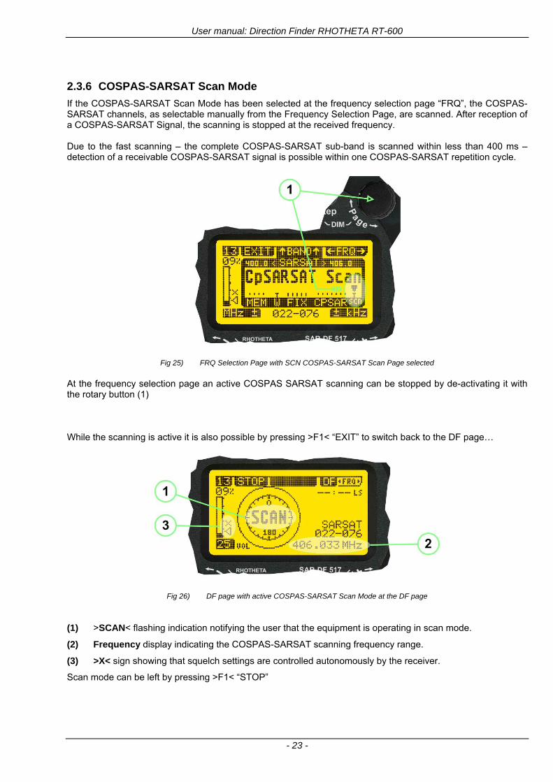
User manual Direction Finder RHOTHETA RT-600
- 23 -
236 COSPAS-SARSAT Scan Mode
If the COSPAS-SARSAT Scan Mode has been selected at the frequency selection page ldquoFRQrdquo the COSPAS-SARSAT channels as selectable manually from the Frequency Selection Page are scanned After reception of a COSPAS-SARSAT Signal the scanning is stopped at the received frequency Due to the fast scanning ndash the complete COSPAS-SARSAT sub-band is scanned within less than 400 ms ndash detection of a receivable COSPAS-SARSAT signal is possible within one COSPAS-SARSAT repetition cycle
Fig 25) FRQ Selection Page with SCN COSPAS-SARSAT Scan Page selected
At the frequency selection page an active COSPAS SARSAT scanning can be stopped by de-activating it with the rotary button (1) While the scanning is active it is also possible by pressing gtF1lt ldquoEXITrdquo to switch back to the DF pagehellip
Fig 26) DF page with active COSPAS-SARSAT Scan Mode at the DF page
(1) gtSCANlt flashing indication notifying the user that the equipment is operating in scan mode
(2) Frequency display indicating the COSPAS-SARSAT scanning frequency range
(3) gtXlt sign showing that squelch settings are controlled autonomously by the receiver
Scan mode can be left by pressing gtF1lt ldquoSTOPrdquo
User manual Direction Finder RHOTHETA RT-600
- 24 -
237 Marine Ship Scan Mode
Fig 27) DF Mode FRQ = 156800 MHz F1 for scan function
If the active frequency (2) is within the VHF Marine Band a fast scan of all ship channels is possible by pushing gtF1lt ldquoSCAN (1) In this scanning mode all marine channels 1 to 88 (156025 to 157450 MHz) are scanned continuously until a signal is received To offer the best monitoring functionality for the user also signals between to channels (4) are detected (scanning without gap) In order to prevent the scan to stop on noisy frequencies it is recommended to start scanning with high squelch settings You can reduce the squelch level in steps until the scan stops on a noisy frequency for the first time Then increase the squelch level slightly This will result in the highest possible scan sensitivity and avoiding noisy channels due to RF disturbances sometimes generated by other equipment in own aircraft
Fig 28) DF Mode active scanning in process
The scanning is stopped by pressing gtF1lt ldquoSTOPrdquo (3)
User manual Direction Finder RHOTHETA RT-600
- 25 -
24 Law Enforcement Operation Law enforcement special ops and other organizations use the RT-600 LE (LAW ENFORCEMENT) version instead of the RT-600 A (STANDARD) version One of the reasons is that the LE version features scanning and tracking of signals like LoJack and ETS as well as signals in the 216000 MHz ndash 220000 MHz band such as medical beacons wristankle transmitters cashasset recovery ldquotagsrdquo etc However the LE version shares many functions in common with the A version such as scanning and tracking in the AIR band COSPAS-SARSAT band etc
241 Power-On procedure
The power-on procedure is the same as described in 211
(1) System Version ldquo(L)rdquo for LAW ENFORCEMENT version
Fig 29) STARTUP Screen (see 211 for details)
242 LoJack Scan Mode Start scanning for a VLU Code
For the convenience of Law Enforcement and other special ops users who frequently engage in tracking SVRS (Stolen Vehicle Recovery System) signals such as LoJack (LoJack Corp FCC 9020 Part 2 SVRS) RHOTHETA has optimized the power-on procedure of the RT-600 LE version so that right after the STARTUP screen the unit displays automatically the LoJack Scan Mode page to start immediately scanning for a valid VLU (Vehicle Location Unit) code without pressing any key
Fig 30) LoJack Scan Mode unit is scanning for a LoJack VLU Code
(1) gtscan LoJacklt DF is scanning for any new LoJack VLU Code
(2) gtEXITlt press F1 to exit and switch directly to DF Mode
User manual Direction Finder RHOTHETA RT-600
- 26 -
243 LoJack Scan Mode from any other page
While operating on any page other than the LoJack Scan page the user can switch directly to LoJack Scan Mode by pressing Hotkey F2 for 2 secs
(1) press Hotkey F2 for 2 secs to switch to the LoJack Scan page
Fig 31) Hotkey F2
User manual Direction Finder RHOTHETA RT-600
- 27 -
244 Manual activation of LoJack Scan Mode
(1) select the LoJack frequency (see also Frequency Selection Page)
(2) press F1 to switch back to the DF MODE
Fig 32) FRQ Selection Page FRQ = LoJack BAND = LoJack (164-174 MHz)
While in DF MODE with adjusted LoJack frequency the user can switch directly to the LoJack Scan by pressing gtF1lt ldquoSCANrdquo
(1) press F1 SCAN to switch to the LoJack Scan page
(2) still no LoJack ID filter used (ID=off) all transmissions are received on the active frequency as example also unwanted tower pulses
Fig 33) DF Mode with LoJack filter OFF
User manual Direction Finder RHOTHETA RT-600
- 28 -
245 Receiving and accepting a new VLU Code
While in LoJack Scan Mode waiting for a VLU Code if a new VLU Code is displayed the user can accept it and switch directly to DF Mode by pressing F2
(1) a new LoJack VLU Code (0001A) has been received
(2) press F2 to accept the new VLU Code (0001A) and switch to DF MODE page with the LoJack filter activated to track only 0001A
Fig 34) LoJack Scan Mode with new VLU Code received
246 Entering a new VLU Code manually
While in LoJack Scan Mode the user can enter a LoJack VLU code also manually
(1 2 3) use the SELECTplusmn and plusmnVALUE knobs to enter a new LoJack VLU Code active ID (0001A)
(4) Press F1 to accept the new VLU Code and switch to DF Mode with the LoJack filter ON to track only 0001A
Fig 35) LoJack Scan Mode with new VLU Code entered manually
User manual Direction Finder RHOTHETA RT-600
- 29 -
247 Tracking one VLU Code while monitoring new VLU Codes
While on DF Mode and tracking a VLU Code (0001A) the user can turn the LoJack switch OFF with F2 also the user can start scanning all VLUs again with F1
0001A is displayed as the active VLU Code filter function is ON only 0001A is tracked
Monitoring of other VLU Codes is active in the background
(1) Press F1 to switch to the LoJack Scan Mode to scan for new VLU Codes
(2) Press F2 to switch LoJack filter OFF
Fig 36) DF Mode with active VLU Code and LoJack filter ON
248 Tracking one VLU Code and receiving a new VLU Code
While on DF MODE page and tracking VLU Code (0001A) in the background a new VLU Code is received and decoded (G2HC7)
(1) The new VLU Code is announced (NEW G2HC7)
(2) Press F1 to switch to LoJack Scan Mode to see the arrival time of G2HC7 and the possibility to change bearing to this new G2HC7
Fig 37) DF Mode with active VLU Code and announcement of new VLU Code
User manual Direction Finder RHOTHETA RT-600
- 30 -
249 Switching to a new VLU Code
While on the LoJack Scan Page tracking one VLU Code (0001A) and notified of a new VLU Code (G2HC7)
(1) press F1 to continue tracking 0001A
(2) press F2 to start tracking G2HC7
(3) Time elapsed since G2HC7 was last received
(4) Time elapsed since 0001A was last received
If F1 is pressed for 2 sec the indicated VLU Code (G2HC7) and ID (0001A) are deleted
Fig 38) LoJack Scan Page with one active VLU Code and one new VLU Code
2410 ldquoBlockingrdquo function of one LoJack VLU Code
The LoJack scan page can also be used to ldquoblockrdquo one unwanted LoJack VLU ID signal by separating the adjusted active ID from any other received LoJack VLU signal This is done by muting the audio (see example below) when a LoJack signal with VLU code ldquo0001Ardquo is received gtgt Any new VLU Code (active LoJack signal) - except for 0001A ndash will be displayed on the top row and generate the audible beep tone
Fig 39) LoJack Scan Page with one active VLU Code and audio OFF
Tip ldquoBlockingrdquo is an important tool for practical missions As example a stolen vehicle with VLU ID ldquo0001Ardquo was tracked in the DF bearing mode The mission
is completed but the VLU is normally still transmitting With the settings above only new VLU signals except the now unwanted ldquo0001Ardquo are audible and displayed in the upper (scan LoJack hellip for new VLU) box
User manual Direction Finder RHOTHETA RT-600
- 31 -
2411 Tracking in the 216 to 220 MHz band
The RT-600 features scanning and bearing functionality in the 216000 MHz to 220000 MHz band The 216000 MHz ndash 220000 MHz band contains frequencies and signals used by special services and tracked by law enforcement special ops and similar organizations These are some of the frequencies and services in this band
CFR 90259 tx 216000 MHz to 220000 MHz
Low Power Radio Service (LPRS) tx 216000 MHz to 217000 MHz
Medical beacons Project Lifesaver tx wristankle tx 213000 MHz to 216000 MHz
ETS tx stolen cashasset recovery tx ldquobaitrdquordquotagrdquo tx 216000 MHz to 220000 MHz tx = transmitter(s) However any future or current user of the Rhotheta RT-600 must be aware that tracking signals on the frequencies listed above may be challenging and even frustrating due mostly to negative factors in some of the transmitters
bull Very low RF power output
bull Inefficient antennas
bull Battery-powered devices with a ldquolow batteryrdquo condition
bull Devices worn or located in conditions of poor RF propagation
bull Devices with channel spacing different than the one specified for the RT-600
These factors can make it very difficult for the DF to receive the signal andor display an accurate bearing Disclaimer For the reasons explained above and even though the RT-600 features top performance in its class RHOTHETA does not offer - and is not to be held responsible for - any guaranteed minimum range or distance to a transmitter in this band
25 Setup Edit Page System settings are displayed in the setup page The functions described in this section should be used by trained personal only
Fig 40) Accessing the Setup Page
The setup page can be accessed by holding down the gtCLRlt (1) and gtREPlt (2) buttons simultaneously and in the same time performing a left-hand turn on the gtPagelt rotary switch (3)
User manual Direction Finder RHOTHETA RT-600
- 32 -
Fig 41) Setup Page
(1) gtStorelt push-button must be pressed in parallel if a value of a setting shall be modified If a value can
be modified the background stops to blink
(2) gtSelectlt rotary switch used to scroll through the menu options The value of the actually activated menu option is high-lighted with dark background and blinking
(3) gtValuelt rotary switch used to change values in menu options (gtStorelt (1) has to be pressed in parallel if a value shall be modified)
(4) gtSN-Ratiolt menu option representing the necessary Signal-To-Noise-Ratio (Difference between signal and noise level) used as criterion for the automatic squelch function Please refer to the chapter ldquoSquelch Operationrdquo for details Default value is 60 dB
(5) gtMounting Positionlt menu option to select Top- or Bottom-Mounting of the DF antenna In case of rooftop installation (eg on land vehicles) ldquoToprdquo shall be selected In case of bottom-down (upside-down) installation (eg on a helicopter) ldquoBotrdquo shall be selected If this option is not selected correctly all bearing values will be mirror-inverted
(6) gtBearing Offsetlt menu option to include a constant offset correction to the bearing indication Bearing values in degrees will be changed according to the offset value
(7) gtMaximum External Dimming Voltage for Legendslt menu option which sets the upper limit of the dimming input voltage for the legends-panel Range=[15 hellip 28]V
(8) gtMinimum External Dimming Voltage for Legendslt menu option which sets the lower limit of the dimming input voltage for the legends-panel Range=[15 hellip 28]V
(9) gtPagelt rotary switch to be turned right-hand to go back to the Direction Finder page A left-hand turn on this rotary switch will show up an additional service page with debug information used for system checks
(10) gtExtended Seriallt It is possible to enable or disable the extended serial data protocol Only of interest if serial data is used by any connected control units like moving maps or computers For detailed information see (Serial interface data protocol (short description)gt at page 46) If there are compatibility problems with already existing older remote control software it is recommended to switch OFF the extended serial data protocol
User manual Direction Finder RHOTHETA RT-600
- 33 -
3 Error messages If an internal error of the device is recognized a corresponding flashing error message will be shown in the DF pages
Fig 42) Error Messages
(1) Error message including error code (in brackets)
(2) Short description of the indicated error
In case of coincidence of various errors the error with the highest priority will be displayed
Error message Error location Reason
Error (12) VOLTDU
Main voltage supply Main Voltage input too low ( 100 V)
Error (11) NO AU
Connection antenna display or Antenna Unit
No serial data (RS485) from Antenna Unit No or damaged connection between antenna and display or damaged antenna unit
Error (10) BAD AU
Connection antenna display
Incompatibility or bad data connection between display and antenna
Error (9) BAD RU
Remote Unit Incompatibility or bad data connection between display and external serial Remote Unit or PC
Error (8) VOLTAU
Antenna Unit Voltage supply at Antenna Unit too low ( 90 V) Main voltage supply too low or considerable drop of voltage between display and antenna
Error (7) BAD DCU
Connection Display Antenna
Incompatibility or bad data connection between antenna and display
Error (6) NO DCU
Connection Display Antenna
No serial data from Display Control Unit to Antenna Unit
Error (5) PLL ERR
antenna Error in synthesizer-oscillator of receiver in Antenna Unit
Error (4) FRQ+OFS
received transmitter Received frequency too high (more than 6 KHz error of transmitter)
Error (3) FRQ-OFS
received transmitter received frequency too low (more than 6 KHZ error of transmitter)
Error (2) DECODE
radio distance transmitter DF
Data Bits of decoded signal (COSPAS-SARSAT or LoJack) defective
Error (1) DATARNG
Incompatibility of data DCU AU
Protocol data bytes out of valid range
Error (0) NO REC
Antenna Unit receiver
Receiver board defective
User manual Direction Finder RHOTHETA RT-600
- 34 -
4 Installation
41 Antenna unit A convenient position of the monopole bearing antenna is crucial for good bearing results The antenna needs an effective ground connection to the body of the aircraft or to the roof of the vehicle If there is no metallic mounting surface available a metallic sheet or similar (net) with connection to ground has to be applied first between vehicle-body and antenna In this hatched area the antenna touches the body ofthe vehicleaircraft In order to obtain a good groundconnection the surface of the body should be bared(Measuring unit [mm])
8 x holes for mounting the antenna unit to the
vehicle aircraft
Fig 43) Antenna Mounting Drawing
User manual Direction Finder RHOTHETA RT-600
- 35 -
411 Influence of antenna location and environment on the bearing accuracy
Recommendations concerning the practical antenna unit location on helicopters and airplanes
The bearing accuracy of the direction finder antenna unit is severely influenced (comparable to an airspeed sensor) by the environment For comparison a perfect high quality speed sensor will not indicate the true airspeed if this sensor is interfered by strong turbulences The direction finder antenna unit acts as a sensor for electromagnetic waves In the near field of this antenna unit any conductive (eg metallic) obstacle will influence the incoming wave field and create reflections which decrease the bearing accuracy These are general physical limitations concerning all types of direction finder systems To achieve the best bearing results it should be considered that the antenna unit is installed as far away as possible from any other vertically polarized conductive structure If possible there should be no reflectors within an area of 2-3 feet around the antenna unit In this worst case example the direction finder will not work properly
Fig 44) Antenna Installed in a Bad Location
In this example the antenna unit is located too close to the cable cutter of the helicopter This cutter will produce strong reflections especially as the length is equal to Lambda4 within the VHF airband
User manual Direction Finder RHOTHETA RT-600
- 36 -
Examples of properly installed direction finder antenna units
Fig 45) Antenna Installed in Good Locations
User manual Direction Finder RHOTHETA RT-600
- 37 -
42 Display and Control Unit
The display control unit may be mounted into a front panel by the means of this mounting drawing
Fig 46) DCU Mounting Drawing
(all dimensions in [mm]) To install or uninstall the display control unit perform the following steps (1) Remove the cover caps of the four rotary switches
(2) Loose the screws visible below the position of the cover caps
(3) Remove the plastic button from the axis of the four rotary switches
(4) Mount dismount the display control unit
(5) Re-install the plastic buttons on the axis of the four rotary switches
(6) Fix the screws so that the plastic buttons are fixed on the axis
(7) Re-install the cover caps on the four rotary switches
User manual Direction Finder RHOTHETA RT-600
- 38 -
43 System Interconnect Wiring Diagram (Also refer to chapter ldquoTechnical Datardquo for details)
Fig 47) System Interconnect Wiring Diagram
6-pol Amphenol plug femalePTG06SE10-6S(SQ)
max length of cable 20 m 9-pol Sub-D plug (femalemale)
User manual Direction Finder RHOTHETA RT-600
- 39 -
5 Technical Data
51 Electric features
Method of bearing Doppler-principle (3 kHz rotational frequency right left rotation)
Bearing accuracy1 plusmn 5deg RMS
Internal resolution 1deg
Bearing Sensitivity VHF AirEmergency le 25 μVm (typical)
VHF Marine le 25 μVm (typical)
UHF Emergency and ETS le 4 μVm (typical)
COSPAS-SARSAT le 4 μVm (typical)
LoJack Decoding (50 Message Error Rate) and bearing le 5 μVm (typical)
Frequency stability plusmn 20 ppm (Δff = plusmn210-6)
Reception frequencies
SAR version (Standard)
Frequency Options
VHF Emergency Band 118000 to 124000 MHz (833 kHz steps AM)
VHF Marine Band 154000 to 163000 MHz ( 500 kHz steps FM) (channel 16 selectable via channel no)
UHF Emergency Band 240000 to 246000 MHz (2500 kHz steps AM)
UHF FM Band 406100 to 410000 MHz ( 500 kHz steps FM)
COSPAS-SARSAT 400000 to 406092 MHz Including 406022 to 406076 MHz (Channel A S)
F1 VHF Air Band 118000 to 136992 MHz
F2 extended VHF Marine Band 137000 to 224995 MHz
F3 extended UHF Air Band 225000 to 399975 MHz
F4 additional UHF FM Band 406100 to 470000 MHz
Reception frequencies
LAW Enforcement version
Frequency Options
VHF Emergency Band 118000 to 124000 MHz (833 kHz steps AM)
VHF Marine Band 154000 to 163000 MHz (500 kHz steps FM) (channel 16 selectable via channel no)
LoJack 164000 to 174000 MHz (125 kHz steps FM)
ETS 216000 to 220000 MHz (10125 kHz AM)
COSPAS-SARSAT 400000 to 406092 MHz Including 406022 to 406076 MHz (Channel A S)
F1VHF Air Band 118000 to 136992 MHz
F2 extended VHF Marine Band 137000 to 163000 MHz
COSPAS-SARSAT fast scan mode
Full automatic detection of any active COSPAS-SARSAT channel A to S within 400 ms
COSPAS-SARSAT decoding
Reception and decoding of COSPAS-SARSAT data signal (112 or 144 bit) specified according to COSPAS-SARSAT
LoJack decoding Selectable LoJack ID display and selective active filtering
Special scanning modes
complete maritime ship band scanning within 3 s (channel 01 hellip 88 also frequencies between 2 channels are included)
1With undisturbed wave field and sufficient field strength Measuring by changing the angle of incidence with the antenna rotating on a revolving table in order to eliminate environmental influences on the results No modulation
User manual Direction Finder RHOTHETA RT-600
- 40 -
Bearable modulation A3E F3E A3X (ELT-modulation) F1D G2D COSPAS-SARSAT Bearing largely independent of modulation
Polarization Vertical
Polarization error 5deg at 60deg field vector rotation
Garbling cone Ca 30deg to the vertical
Time of response2 50 ms (with sufficient reception field strength)
LC-graphic display 128 x 64 pixels supertwist transflective extended range of temperature dark-blue display on yellow-green background background light Freely adjustable (exponential) dimming of brightness
NVG cockpit design Fully compatible NVIS Green B display Control Unit optional
Operating voltage 275 V nominal 12 V to 35 V DC
Current consumption LCD-background light Off max 500 mA (12 V DC) max 250 mA (24 V DC)
LCD-background light 100 max 750 mA (12 V DC) max 350 mA (24 V DC)
LCD-background light 100 max 900 mA (12 V DC) with NVG Option max 400 mA (24 V DC)
Audio out For external speaker approx 2 W (4 Ω)
Serial data interface Serial interface RS-232 (9600 baud 8 data bits 1 stop bit no parity)
2Very weak signals can considerably increase the time of response
User manual Direction Finder RHOTHETA RT-600
- 41 -
52 Interface External connections (optional at Sub-D 9-pol Male connector)
Dimming
Pin 8
external voltage input for variable dimming of legends
(optional)
Analog input signal for variable control of the legends illumination Input voltage range is freely adjustable in the range of 15 hellip 28 V in the setup menu Refer to chapter ldquoSetup Pagerdquo Default setting 8 hellip28 V (8 V = Off 28 V = max dimming for legends)
Input Impedance gt 50 k
Pin 6 night status line for LCD
dimming (optional)
Low-active (as example switch to ground) At input voltage lt 25 VDC the LCD dimming operates in nightNVG mode Maximum brightness ca 4 of daydefault mode brightness
Input Impedance gt 50 k
Pin 4 NVG status line for LCD
dimming (optional)
Low-active (as example switch to ground) At input voltage lt 25 VDC the LCD dimming operates in nightNVG mode Maximum brightness ca 4 of daydefault mode brightness
Input Impedance gt 50 k
AudioLF
Pin 7 Audio output signal
AC coupled voltage source with very low inner resistance Maximum output voltage ca 8 VPP = 283V RMS at maximum Volume Maximum output power ca 2 W with 4 speaker
If a headphone is connected ([32hellip600] 100mW) we recommend using a resistor (18 025 W) between audio output and headphone to prevent damage of the headphone
Serial interface RS232 (9600 baud 8 data bits 1 stop bit no parity)
Pin 3 TXD Serial output (ca plusmn10 V)
Pin 2 RXD Serial input (ca plusmn10 V)
User manual Direction Finder RHOTHETA RT-600
- 42 -
53 Mechanical features
Temperature range
Display Control Unit permissible operating temperature3 -20 degC +60 degC permissible storage temperature -30 degC +80 degC
Antenna Unit permissible operating temperature3 -40 degC +60 degC permissible storage temperature -55 degC +80 degC
Protective system Antenna Unit IP 67
Weights Display Control Unit 250 g Antenna Unit 2000 g
Dimensions Display Control Unit 82 mm x 82 mm x 43 mm (width x height x depth) Antenna Unit 270 mm x 185 mm
Fig 48) DCU Mechanical Drawing (all dimensions in [mm])
3 For temperatures lower than ndash10deg C a warm-up period of 15 min should be allowed
User manual Direction Finder RHOTHETA RT-600
- 43 -
Fig 49) AU Mechanical Drawing (all dimensions in [mm])
User manual Direction Finder RHOTHETA RT-600
- 44 -
6 Appendix
61 Frequency Ranges
User manual Direction Finder RHOTHETA RT-600
- 45 -
62 Frequencies of channels on maritime band (only for standard [A] version) Frequency-range of the RT-600 in the maritime band 156000 MHz 162025 MHz
Channel No frequency (ship - station) Frequency (coast - station)
1 156050 MHz 160650 MHz 2 156100 MHz 160700 MHz 3 156150 MHz 160750 MHz 4 156200 MHz 160800 MHz 5 156250 MHz 160850 MHz 6 156300 MHz 160900 MHz 7 156350 MHz 160950 MHz 8 156400 MHz 9 156450 MHz
10 156500 MHz 11 156550 MHz 12 156600 MHz 13 156650 MHz 14 156700 MHz 15 156750 MHz 16 156800 MHz 17 156850 MHz 18 156900 MHz 161500 MHz 19 156950 MHz 161550 MHz 20 157000 MHz 161600 MHz 21 157050 MHz 161650 MHz 22 157100 MHz 161700 MHz 23 157150 MHz 161750 MHz 24 157200 MHz 161800 MHz 25 157250 MHz 161850 MHz 26 157300 MHz 161900 MHz 27 157350 MHz 161950 MHz 28 157400 MHz 162000 MHz 60 156025 MHz 160625 MHz 61 156075 MHz 160675 MHz 62 156125 MHz 160725 MHz 63 156175 MHz 160775 MHz 64 156225 MHz 160825 MHz 65 156275 MHz 160875 MHz 66 156325 MHz 160925 MHz 67 156375 MHz 68 156425 MHz 69 156475 MHz 70 156525 MHz 71 156575 MHz 72 156625 MHz 73 156675 MHz 74 156725 MHz 75 156775 MHz 76 156825 MHz 77 156875 MHz 78 156925 MHz 161525 MHz 79 156975 MHz 161575 MHz 80 157025 MHz 161625 MHz 81 157075 MHz 161675 MHz 82 157125 MHz 161725 MHz 83 157175 MHz 161775 MHz 84 157225 MHz 161825 MHz 85 157275 MHz 161875 MHz 86 157325 MHz 161925 MHz 87 157375 MHz 161975 MHz 88 157425 MHz 162025 MHz
User manual Direction Finder RHOTHETA RT-600
- 46 -
63 Serial interface data protocol (short description)
631 General
Interface parameters RS232 9600 Baud 8 databits 1 stopbit no parity LSB sent first Timing of serial data For accurate use of the serial data (even for the optional serial input commands) the correct timing is mandatory The DCU (Display Control Unit) sends out via the RS-232 Pins (see 43 System Interconnect Wiring Diagram page 38) cyclic and autonomous every approx 250300 ms a binary data stream which contains all relevant DF-bearing information The output data contains one or two blocks of binary data (see next picture with accordingly description) The optional serial input is only used if changes (as example frequency change) are done by additional remote control units
Fig 50) Timing of serial data
Serial standard output
This output data is always available and contains all relevant DF-bearing data For detailed content see page 47
Optional extended serial output
This data contains some additional information like as example CospasSarsat or LoJack decoding and ID data For detailed content see page 50 The data is only available with DCU Software [Rev ge 320] and if this optional data block is configured as ON = enabled (see Setup Edit Page point (10) )
Even to avoid compatibility problems with already existing older remote control software it is possible to disable switch off this additional data block (see Setup Edit Page point (10) )
Optional serial input
Only used for optional commands to control DCU parameters If as example the direction finder frequency is changed remotely there is send to the DCU one time this data block with the new frequency For detailed content see page 52
User manual Direction Finder RHOTHETA RT-600
- 47 -
632 Serial standard output (protocol description)
Specification serial standard output
The binary data stream with a length of 39 bytes starts with a header byte (value = hex 0xA0 as ID for DF Mode) The next bytes contain different values for status bearing information and also service The last byte is used for data stream checksum control Remark This is a binary data protocol So every byte value from 0dec hellip 255dec (0x00 hellip 0xFF) is possible Because of this it is not allowed to realize a start byte detection by the content (0xA0) The idle line detection is recommended for detection the end of message Register of databytes (for details see next page)
byte no
[0] Header = 0xA0 Id for DF Mode
[1] Number = 39 = bytes in the complete message (including header and checksumbyte)
[2] Status (1) HSB [x|x|x|x|x|x|x|x] LSB | | | | | | | --gt (0) Receiving | | | | | | ----gt (1) Squelch controlled by AU (X) | | | | | ------gt (2) Permission RL Calibration | | | | --------gt (3) Line Night | | | ----------gt (4) Line NVG | | ------------gt (5) Dimming External | --------------gt (6) Autosquelch Active ----------------gt (7) 0=Standard Version 1=LE Version
[3] Status (2) HSB [x|x|x|x|x|x|x|x] LSB | ----------------gt (7) 0=Standard 1=extended serial dataprotocol = ONactive
[45] Error (Bits[120])
[6] Actual DCU Page
[7] Volume [0hellip100]
[811] Frequency [Hz]
[12] Active Band
[13] Actual Squelchlevel [0hellip60]
[14] Audio-Line amp_NF_Test Output
[15] (Not used)
[1617] Voltage_DCU ([0hellip335]=[0 hellip 335]V
[1819] Voltage_AU ([0hellip255]=[0 hellip 255]V
[20] Temperature_AU [-68hellip+127]degC
[21] Frequency Offset [-99hellip+99]
[2225] ServiceTest values (mode dependent test values for service only)
26 (Not used reserved)
[27] Level [0hellip100]
[2829] Bearing Averaged [0hellip359]deg relative
[3031] Bearing Live_Min [0hellip359]deg relative
[3233] Bearing Live_Max [0hellip359]deg relative
[34] Test Value PS-RAM Right Rotation[0hellip178] (for service only)
[35] Test Value PS-RAM Left Rotation [0hellip178] (for service only)
[3637] (Not used reserved)
[38] Checksum is the 2rsquos complement of the modulo-256 sum of all bytes without checksum-byte [0n-1]
User manual Direction Finder RHOTHETA RT-600
- 48 -
Detailed Description of important values for practical use
Status byte [2] Receiving Bit 0 of this value (LSB) indicates signal receiving Bit 0 = 0 then no signal is received and so on no bearing is available Bit 0 = 1 then bearing is possible Bit 1 if(1) then Squelch is controlled by AU (active at modes CospasSarsat Decode CospasSarsat Scanning LoJack with Filter=ID only)
Error bytes [4hellip5] 16 bit value each set bit corresponds to the error no (Refer to the chapter Error messages) Example - 0x0000 No error - 0x0800 Bit No 11 Set ( = No AU Error)
Actual DCU Page byte [6] indicates actual operating mode of DCU 0 = Standard bearing page 1 = Frequency memory page 2 = CospasSarsat decoding page 3 = LoJack decoding page (ID edit)
Frequency bytes [8hellip11] 32 bit value actual adjusted frequency [Hz] Example - 0x073DF160 1215000000 121500 MHz
Active Band Standard Version [A] 0=VHF Airband 1=VHF Marineband sea 2=VHF Marineband coast 3=UHV Airband 4=CospasSarsat LE Version [L] 0=VHF Airband 1=LoJack 2=Lifesaver 3=ETS 4=CospasSarsat
Actual Squelchlevel byte [13] Range [0hellip60] without signal the actual squelchlevel should always be adjusted a little bit over the noise level (Refer to the chapter Squelch operation)
Level byte [27] Range [099] actual receiving level (without signal this value is equal to the noise level) If a signal is received then this value corresponds to the signal strength of this signal
Relative Bearing averaged byte [2829] 16 bit value Range [0hellip359 0xFFFF] if the value = 0xFFFF then no valid bearing is available otherwise this value contains the actual averaged bearing information in Deg [0deg359deg] Example - 0X0114 276deg bearing (= left side oriented to heading)
Bearing Live MinMax byte[3031] amp [3233] - 16 bit values Range [0hellip359 0xFFFF] Only for signal quality or additional information ndash NOT recommended for bearing indication The relative live bearing field contains the maxmin bearing in degrees without averaging The relative live bearing reacts faster than the normal relative bearing but it has not the precision of the averaged bearing The MinMax Bearing Values are calculated within a time period of approx 250 ms If they are very close together (for example ldquo124rdquo and ldquo128rdquo degrees) then the signal quality is quite good A wide span of the minmax values (for example ldquo97rdquo and ldquo162rdquo) shows very noisy but nevertheless bearable signal quality
User manual Direction Finder RHOTHETA RT-600
- 49 -
633 DCU Info output (protocol description)
Specification DCU Info output
Remark This protocol is only available while the SetupEdit page is activated at the DCU
byte no
[0] Header = 0xAF Id for DCU Info Mode
[1] Number = 39 = bytes in the complete message (including header and checksumbyte)
[2]
(see standard output) [3]
[45]
[621] Info String of 15 byteschars the string contains Information about Unit Variant Software Version and Serial No
Example Byte [318] =
|--AU ID---||Var-||---Software Version---| |-------------- Serial No---------------| [0x44][0x55][0x41][0x33][0x2E][0x33][0x30][0x3A][0x20][0x20][0x30][0x31][0x32][0x33][0x34][0x00] rsquoDrsquo rsquoUrsquo rsquoArsquo rsquo3rsquo rsquorsquo rsquo3rsquo rsquo0rsquo rsquorsquo rsquo rsquo rsquo rsquo rsquo0rsquo rsquo1rsquo rsquo2rsquo rsquo3rsquo rsquo4rsquo rsquoENDrsquo | | | | __________________ | | ________________________ | n n n | | n n n n n | (Software Version) | | (Serial No) | gt rsquoArsquo = Standard Variant gt rsquoLrsquo = Law Enforcement Variant
User manual Direction Finder RHOTHETA RT-600
- 50 -
634 Optional extended serial output (protocol description)
The data content depends on the actual mode of the direction finder To get special data the direction finder has first to be switched to the equivalent mode
COSPAS-SARSAT Decoding data
This data is only available and valid if Display Control Unit with actual software Rev ge 320 (see Power-On procedure page 10) Configuration of Extended serial = ON (see Setup Edit Page point (10) ) Direction Finder COSPAS-SARSAT decoding mode is activated by selecting the corresponding page
(see COSPAS-SARSAT Decode Window page 20 and page 21) and so on Header (byte 0 of data) = 0x91
A valid COSPAS-SARSAT decoding data protocol is always marked by the first data byte (header = 0x91) Always after receiving and decoding of a valid COSPAS-SARSAT pulse the complete data protocol with 33 bytes is send out one time
Byte No
[0] Header = 0x91 (Identification for CPSarsat decoding mode)
[1] Number of bytes - 7 if no decoded pulse is available - 33 if new pulse was received and is available
[2] Error
[3] Bit[0] - 0 =gt No new 406 MSG (decoded data) available - 1 =gt New valid 406 MSG available (Sync amp Frame Ok) Check Error Status for Bit-Errors
Bit[61] AutoSquelch Level valid range [060] ( decimal)
Bit[7] = 1 Squelch controlled by AU
[4] Signallevel of received signal valid range [099] ( decimal)
[5] Voltage of Antenna Unit Power Supply input valid range [80255] (decimal = 80 255 V DC)
[6] Temperature inside Antenna Unit valid range [-50+100] (degC signed byte value)
The following databytes are only available if a correct CPSarsat puls gets received and decoded with correct checksum
[724] 18 x Databytes complete orginal CPSarsat 406 decoded message (144 bit)
Databyte Nr [ Byte 7 ] [ Byte 8 ] [Byte9 Byte24] 406 MSG Bit Nr [1 2 3 4 5 6 7 8] [9 10 11 12 13 14 15 16] [17 144]
[25] SN-Flag valid values 0x53=rsquoSrsquo 0x4E=rsquoNrsquo 0x2D=rsquo-rsquo if no GPS data available
GPS-Position Latitude
[26] Deg valid values [090] (decimal Deg) 0xFF if no GPS data available
[27] Min valid values [059] (decimal Deg) 0xFF if no GPS data available
[28] Sec valid values [059] (decimal Deg) 0xFF if no GPS data available
[29] WE-Flag valid values 0x57=rsquoWrsquo 0x45=rsquoErsquo 0x2D=rsquo-rsquo if no GPS data available
GPS-Position Longitude
[30] Deg valid values [0180] (decimal Deg) 0xFF if no GPS data available
[31] Min valid values [059] (decimal Deg) 0xFF if no GPS data available
[32] Sec valid values [059] (decimal Deg) 0xFF if no GPS data available
User manual Direction Finder RHOTHETA RT-600
- 51 -
LoJack ID data
This data is only available and valid if Display Control Unit with actual software Rev ge 320 (see Power-On procedure page 10) Direction Finder of variant [L] Law Enforcement Configuration of Extended serial = ON (see Setup Edit Page point (10) ) Direction Finder is working with active LoJack gtID Filterlt Header (byte 0 of data) = 0x93 or 0x94
Valid LoJack ID decoding data is always marked by the first data byte (header = 0x93 or 0x94)
Byte No
[0] Header = 0x93 LoJack ID editing sub-page is selected Filter = VLU all valid and received LoJack pulses are indicated = 0x94 Lojack Decode amp DF Mode with active Filter = ID
[1] Number of bytes in the complete data stream - decimal 26 = default value
[2] Nonrelevant
[3] Bit[0] Receiving OnOff - 0 =gt No Receiving no bearing - 1 =gt new LoJack pulse received
[412] Nonrelevant
[1317] Lojack ID
Replay Code 5 x ASCII Chars ldquoNo BIOZrdquo set
Example ASCII = ldquo000R1rdquo
18 Receiver Level Out Max [099]
19
LoJack Decoder Status [07] - 0 Off - 1 Wait for Preamble - 2 Preamble Ok - 3 FlagPattern Ok - 4 Data BitError gt 1 - 5 Data Ok (No VLU) - 6 VLU Ok - 7 ID Ok (Filter=IDONLY)
[2025] Nonrelevant
Remark Only if byte no [3] bit [0] gets ldquo1rdquo (Receiving On) then an active LoJack pulse is received and so on the corresponding LoJack ID valid otherwise the LoJack ID only shows the actual adjusted LoJack Filter ID of the direction finder
User manual Direction Finder RHOTHETA RT-600
- 52 -
635 Optional serial input (protocol description)
Specification serial input (optional)
The serial input is normally used for service and maintenance only Nevertheless it is possible via this interface to remote control the actual frequency and the squelchlevel of the DF system If a valid data stream is send to the DF then the actual frequency selection at the DCU is switched to Block2 AUX0 At this memory channel the new frequency is stored and used automatically (Refer to the chapter Frequency Selection Page) If the frequency is changed (by one valid data stream) no more serial input is necessary The actual frequency can be changed again at any time by manual operation at the DCU The timing of serial input (if used) is strictly fixed The optional serial input has to take place directly after a complete serial output (max 50 ms delay time) If a new changed frequency is commanded to the DCU via this serial input interface it can take up to 1 sec of time until this new frequency is ready for operationbearing It is strictly not recommended to use the frequency remote control for any scan mode The frequency control has to be used for static frequency change only Register of databytes
byte no
[0] Header 0xC0
[1] Number of bytes in the complete message (including header and checksumbyte)
[23] (not used for normal operation any byte values allowed)
[4] Volume [0100]
[58] Frequency [Hz] (frequency is rounded to the according grid automatically)
Valid Range for Standard Version Valid Range for LE Version
118000000 hellip 123000000 [Hz] 8333 kHz 118000000 hellip 123000000 [Hz] 8333 kHz
156050000 hellip 162025000 [Hz] 5000 kHz 164000000 hellip 174000000 [Hz] 8333 kHz
201000000 hellip 215995000 [Hz] 5000 kHz
240000000 hellip 246000000 [Hz] 8333 kHz 216000000 hellip 218995000 [Hz] 12500 kHz219000000 hellip 220000000 [Hz] 10000 kHz
400000000 hellip 410000000 [Hz] 8333 kHz 400000000 hellip 410000000 [Hz] 8333 kHz
[9] Squelchlevel Manual = [0hellip60] Autosql= [ -1] Warning use only for pulsed signals (as example CpSarsat LoJack)
[10] (not used for normal operation any byte values allowed)
[11] Internal Dimming [0100]
[12] Checksum is the 2rsquos complement of the modulo-256 sum of all bytes without checksum-byte [0n-1]
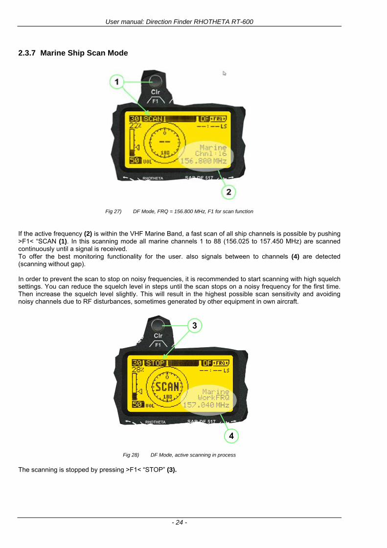
User manual Direction Finder RHOTHETA RT-600
- 24 -
237 Marine Ship Scan Mode
Fig 27) DF Mode FRQ = 156800 MHz F1 for scan function
If the active frequency (2) is within the VHF Marine Band a fast scan of all ship channels is possible by pushing gtF1lt ldquoSCAN (1) In this scanning mode all marine channels 1 to 88 (156025 to 157450 MHz) are scanned continuously until a signal is received To offer the best monitoring functionality for the user also signals between to channels (4) are detected (scanning without gap) In order to prevent the scan to stop on noisy frequencies it is recommended to start scanning with high squelch settings You can reduce the squelch level in steps until the scan stops on a noisy frequency for the first time Then increase the squelch level slightly This will result in the highest possible scan sensitivity and avoiding noisy channels due to RF disturbances sometimes generated by other equipment in own aircraft
Fig 28) DF Mode active scanning in process
The scanning is stopped by pressing gtF1lt ldquoSTOPrdquo (3)
User manual Direction Finder RHOTHETA RT-600
- 25 -
24 Law Enforcement Operation Law enforcement special ops and other organizations use the RT-600 LE (LAW ENFORCEMENT) version instead of the RT-600 A (STANDARD) version One of the reasons is that the LE version features scanning and tracking of signals like LoJack and ETS as well as signals in the 216000 MHz ndash 220000 MHz band such as medical beacons wristankle transmitters cashasset recovery ldquotagsrdquo etc However the LE version shares many functions in common with the A version such as scanning and tracking in the AIR band COSPAS-SARSAT band etc
241 Power-On procedure
The power-on procedure is the same as described in 211
(1) System Version ldquo(L)rdquo for LAW ENFORCEMENT version
Fig 29) STARTUP Screen (see 211 for details)
242 LoJack Scan Mode Start scanning for a VLU Code
For the convenience of Law Enforcement and other special ops users who frequently engage in tracking SVRS (Stolen Vehicle Recovery System) signals such as LoJack (LoJack Corp FCC 9020 Part 2 SVRS) RHOTHETA has optimized the power-on procedure of the RT-600 LE version so that right after the STARTUP screen the unit displays automatically the LoJack Scan Mode page to start immediately scanning for a valid VLU (Vehicle Location Unit) code without pressing any key
Fig 30) LoJack Scan Mode unit is scanning for a LoJack VLU Code
(1) gtscan LoJacklt DF is scanning for any new LoJack VLU Code
(2) gtEXITlt press F1 to exit and switch directly to DF Mode
User manual Direction Finder RHOTHETA RT-600
- 26 -
243 LoJack Scan Mode from any other page
While operating on any page other than the LoJack Scan page the user can switch directly to LoJack Scan Mode by pressing Hotkey F2 for 2 secs
(1) press Hotkey F2 for 2 secs to switch to the LoJack Scan page
Fig 31) Hotkey F2
User manual Direction Finder RHOTHETA RT-600
- 27 -
244 Manual activation of LoJack Scan Mode
(1) select the LoJack frequency (see also Frequency Selection Page)
(2) press F1 to switch back to the DF MODE
Fig 32) FRQ Selection Page FRQ = LoJack BAND = LoJack (164-174 MHz)
While in DF MODE with adjusted LoJack frequency the user can switch directly to the LoJack Scan by pressing gtF1lt ldquoSCANrdquo
(1) press F1 SCAN to switch to the LoJack Scan page
(2) still no LoJack ID filter used (ID=off) all transmissions are received on the active frequency as example also unwanted tower pulses
Fig 33) DF Mode with LoJack filter OFF
User manual Direction Finder RHOTHETA RT-600
- 28 -
245 Receiving and accepting a new VLU Code
While in LoJack Scan Mode waiting for a VLU Code if a new VLU Code is displayed the user can accept it and switch directly to DF Mode by pressing F2
(1) a new LoJack VLU Code (0001A) has been received
(2) press F2 to accept the new VLU Code (0001A) and switch to DF MODE page with the LoJack filter activated to track only 0001A
Fig 34) LoJack Scan Mode with new VLU Code received
246 Entering a new VLU Code manually
While in LoJack Scan Mode the user can enter a LoJack VLU code also manually
(1 2 3) use the SELECTplusmn and plusmnVALUE knobs to enter a new LoJack VLU Code active ID (0001A)
(4) Press F1 to accept the new VLU Code and switch to DF Mode with the LoJack filter ON to track only 0001A
Fig 35) LoJack Scan Mode with new VLU Code entered manually
User manual Direction Finder RHOTHETA RT-600
- 29 -
247 Tracking one VLU Code while monitoring new VLU Codes
While on DF Mode and tracking a VLU Code (0001A) the user can turn the LoJack switch OFF with F2 also the user can start scanning all VLUs again with F1
0001A is displayed as the active VLU Code filter function is ON only 0001A is tracked
Monitoring of other VLU Codes is active in the background
(1) Press F1 to switch to the LoJack Scan Mode to scan for new VLU Codes
(2) Press F2 to switch LoJack filter OFF
Fig 36) DF Mode with active VLU Code and LoJack filter ON
248 Tracking one VLU Code and receiving a new VLU Code
While on DF MODE page and tracking VLU Code (0001A) in the background a new VLU Code is received and decoded (G2HC7)
(1) The new VLU Code is announced (NEW G2HC7)
(2) Press F1 to switch to LoJack Scan Mode to see the arrival time of G2HC7 and the possibility to change bearing to this new G2HC7
Fig 37) DF Mode with active VLU Code and announcement of new VLU Code
User manual Direction Finder RHOTHETA RT-600
- 30 -
249 Switching to a new VLU Code
While on the LoJack Scan Page tracking one VLU Code (0001A) and notified of a new VLU Code (G2HC7)
(1) press F1 to continue tracking 0001A
(2) press F2 to start tracking G2HC7
(3) Time elapsed since G2HC7 was last received
(4) Time elapsed since 0001A was last received
If F1 is pressed for 2 sec the indicated VLU Code (G2HC7) and ID (0001A) are deleted
Fig 38) LoJack Scan Page with one active VLU Code and one new VLU Code
2410 ldquoBlockingrdquo function of one LoJack VLU Code
The LoJack scan page can also be used to ldquoblockrdquo one unwanted LoJack VLU ID signal by separating the adjusted active ID from any other received LoJack VLU signal This is done by muting the audio (see example below) when a LoJack signal with VLU code ldquo0001Ardquo is received gtgt Any new VLU Code (active LoJack signal) - except for 0001A ndash will be displayed on the top row and generate the audible beep tone
Fig 39) LoJack Scan Page with one active VLU Code and audio OFF
Tip ldquoBlockingrdquo is an important tool for practical missions As example a stolen vehicle with VLU ID ldquo0001Ardquo was tracked in the DF bearing mode The mission
is completed but the VLU is normally still transmitting With the settings above only new VLU signals except the now unwanted ldquo0001Ardquo are audible and displayed in the upper (scan LoJack hellip for new VLU) box
User manual Direction Finder RHOTHETA RT-600
- 31 -
2411 Tracking in the 216 to 220 MHz band
The RT-600 features scanning and bearing functionality in the 216000 MHz to 220000 MHz band The 216000 MHz ndash 220000 MHz band contains frequencies and signals used by special services and tracked by law enforcement special ops and similar organizations These are some of the frequencies and services in this band
CFR 90259 tx 216000 MHz to 220000 MHz
Low Power Radio Service (LPRS) tx 216000 MHz to 217000 MHz
Medical beacons Project Lifesaver tx wristankle tx 213000 MHz to 216000 MHz
ETS tx stolen cashasset recovery tx ldquobaitrdquordquotagrdquo tx 216000 MHz to 220000 MHz tx = transmitter(s) However any future or current user of the Rhotheta RT-600 must be aware that tracking signals on the frequencies listed above may be challenging and even frustrating due mostly to negative factors in some of the transmitters
bull Very low RF power output
bull Inefficient antennas
bull Battery-powered devices with a ldquolow batteryrdquo condition
bull Devices worn or located in conditions of poor RF propagation
bull Devices with channel spacing different than the one specified for the RT-600
These factors can make it very difficult for the DF to receive the signal andor display an accurate bearing Disclaimer For the reasons explained above and even though the RT-600 features top performance in its class RHOTHETA does not offer - and is not to be held responsible for - any guaranteed minimum range or distance to a transmitter in this band
25 Setup Edit Page System settings are displayed in the setup page The functions described in this section should be used by trained personal only
Fig 40) Accessing the Setup Page
The setup page can be accessed by holding down the gtCLRlt (1) and gtREPlt (2) buttons simultaneously and in the same time performing a left-hand turn on the gtPagelt rotary switch (3)
User manual Direction Finder RHOTHETA RT-600
- 32 -
Fig 41) Setup Page
(1) gtStorelt push-button must be pressed in parallel if a value of a setting shall be modified If a value can
be modified the background stops to blink
(2) gtSelectlt rotary switch used to scroll through the menu options The value of the actually activated menu option is high-lighted with dark background and blinking
(3) gtValuelt rotary switch used to change values in menu options (gtStorelt (1) has to be pressed in parallel if a value shall be modified)
(4) gtSN-Ratiolt menu option representing the necessary Signal-To-Noise-Ratio (Difference between signal and noise level) used as criterion for the automatic squelch function Please refer to the chapter ldquoSquelch Operationrdquo for details Default value is 60 dB
(5) gtMounting Positionlt menu option to select Top- or Bottom-Mounting of the DF antenna In case of rooftop installation (eg on land vehicles) ldquoToprdquo shall be selected In case of bottom-down (upside-down) installation (eg on a helicopter) ldquoBotrdquo shall be selected If this option is not selected correctly all bearing values will be mirror-inverted
(6) gtBearing Offsetlt menu option to include a constant offset correction to the bearing indication Bearing values in degrees will be changed according to the offset value
(7) gtMaximum External Dimming Voltage for Legendslt menu option which sets the upper limit of the dimming input voltage for the legends-panel Range=[15 hellip 28]V
(8) gtMinimum External Dimming Voltage for Legendslt menu option which sets the lower limit of the dimming input voltage for the legends-panel Range=[15 hellip 28]V
(9) gtPagelt rotary switch to be turned right-hand to go back to the Direction Finder page A left-hand turn on this rotary switch will show up an additional service page with debug information used for system checks
(10) gtExtended Seriallt It is possible to enable or disable the extended serial data protocol Only of interest if serial data is used by any connected control units like moving maps or computers For detailed information see (Serial interface data protocol (short description)gt at page 46) If there are compatibility problems with already existing older remote control software it is recommended to switch OFF the extended serial data protocol
User manual Direction Finder RHOTHETA RT-600
- 33 -
3 Error messages If an internal error of the device is recognized a corresponding flashing error message will be shown in the DF pages
Fig 42) Error Messages
(1) Error message including error code (in brackets)
(2) Short description of the indicated error
In case of coincidence of various errors the error with the highest priority will be displayed
Error message Error location Reason
Error (12) VOLTDU
Main voltage supply Main Voltage input too low ( 100 V)
Error (11) NO AU
Connection antenna display or Antenna Unit
No serial data (RS485) from Antenna Unit No or damaged connection between antenna and display or damaged antenna unit
Error (10) BAD AU
Connection antenna display
Incompatibility or bad data connection between display and antenna
Error (9) BAD RU
Remote Unit Incompatibility or bad data connection between display and external serial Remote Unit or PC
Error (8) VOLTAU
Antenna Unit Voltage supply at Antenna Unit too low ( 90 V) Main voltage supply too low or considerable drop of voltage between display and antenna
Error (7) BAD DCU
Connection Display Antenna
Incompatibility or bad data connection between antenna and display
Error (6) NO DCU
Connection Display Antenna
No serial data from Display Control Unit to Antenna Unit
Error (5) PLL ERR
antenna Error in synthesizer-oscillator of receiver in Antenna Unit
Error (4) FRQ+OFS
received transmitter Received frequency too high (more than 6 KHz error of transmitter)
Error (3) FRQ-OFS
received transmitter received frequency too low (more than 6 KHZ error of transmitter)
Error (2) DECODE
radio distance transmitter DF
Data Bits of decoded signal (COSPAS-SARSAT or LoJack) defective
Error (1) DATARNG
Incompatibility of data DCU AU
Protocol data bytes out of valid range
Error (0) NO REC
Antenna Unit receiver
Receiver board defective
User manual Direction Finder RHOTHETA RT-600
- 34 -
4 Installation
41 Antenna unit A convenient position of the monopole bearing antenna is crucial for good bearing results The antenna needs an effective ground connection to the body of the aircraft or to the roof of the vehicle If there is no metallic mounting surface available a metallic sheet or similar (net) with connection to ground has to be applied first between vehicle-body and antenna In this hatched area the antenna touches the body ofthe vehicleaircraft In order to obtain a good groundconnection the surface of the body should be bared(Measuring unit [mm])
8 x holes for mounting the antenna unit to the
vehicle aircraft
Fig 43) Antenna Mounting Drawing
User manual Direction Finder RHOTHETA RT-600
- 35 -
411 Influence of antenna location and environment on the bearing accuracy
Recommendations concerning the practical antenna unit location on helicopters and airplanes
The bearing accuracy of the direction finder antenna unit is severely influenced (comparable to an airspeed sensor) by the environment For comparison a perfect high quality speed sensor will not indicate the true airspeed if this sensor is interfered by strong turbulences The direction finder antenna unit acts as a sensor for electromagnetic waves In the near field of this antenna unit any conductive (eg metallic) obstacle will influence the incoming wave field and create reflections which decrease the bearing accuracy These are general physical limitations concerning all types of direction finder systems To achieve the best bearing results it should be considered that the antenna unit is installed as far away as possible from any other vertically polarized conductive structure If possible there should be no reflectors within an area of 2-3 feet around the antenna unit In this worst case example the direction finder will not work properly
Fig 44) Antenna Installed in a Bad Location
In this example the antenna unit is located too close to the cable cutter of the helicopter This cutter will produce strong reflections especially as the length is equal to Lambda4 within the VHF airband
User manual Direction Finder RHOTHETA RT-600
- 36 -
Examples of properly installed direction finder antenna units
Fig 45) Antenna Installed in Good Locations
User manual Direction Finder RHOTHETA RT-600
- 37 -
42 Display and Control Unit
The display control unit may be mounted into a front panel by the means of this mounting drawing
Fig 46) DCU Mounting Drawing
(all dimensions in [mm]) To install or uninstall the display control unit perform the following steps (1) Remove the cover caps of the four rotary switches
(2) Loose the screws visible below the position of the cover caps
(3) Remove the plastic button from the axis of the four rotary switches
(4) Mount dismount the display control unit
(5) Re-install the plastic buttons on the axis of the four rotary switches
(6) Fix the screws so that the plastic buttons are fixed on the axis
(7) Re-install the cover caps on the four rotary switches
User manual Direction Finder RHOTHETA RT-600
- 38 -
43 System Interconnect Wiring Diagram (Also refer to chapter ldquoTechnical Datardquo for details)
Fig 47) System Interconnect Wiring Diagram
6-pol Amphenol plug femalePTG06SE10-6S(SQ)
max length of cable 20 m 9-pol Sub-D plug (femalemale)
User manual Direction Finder RHOTHETA RT-600
- 39 -
5 Technical Data
51 Electric features
Method of bearing Doppler-principle (3 kHz rotational frequency right left rotation)
Bearing accuracy1 plusmn 5deg RMS
Internal resolution 1deg
Bearing Sensitivity VHF AirEmergency le 25 μVm (typical)
VHF Marine le 25 μVm (typical)
UHF Emergency and ETS le 4 μVm (typical)
COSPAS-SARSAT le 4 μVm (typical)
LoJack Decoding (50 Message Error Rate) and bearing le 5 μVm (typical)
Frequency stability plusmn 20 ppm (Δff = plusmn210-6)
Reception frequencies
SAR version (Standard)
Frequency Options
VHF Emergency Band 118000 to 124000 MHz (833 kHz steps AM)
VHF Marine Band 154000 to 163000 MHz ( 500 kHz steps FM) (channel 16 selectable via channel no)
UHF Emergency Band 240000 to 246000 MHz (2500 kHz steps AM)
UHF FM Band 406100 to 410000 MHz ( 500 kHz steps FM)
COSPAS-SARSAT 400000 to 406092 MHz Including 406022 to 406076 MHz (Channel A S)
F1 VHF Air Band 118000 to 136992 MHz
F2 extended VHF Marine Band 137000 to 224995 MHz
F3 extended UHF Air Band 225000 to 399975 MHz
F4 additional UHF FM Band 406100 to 470000 MHz
Reception frequencies
LAW Enforcement version
Frequency Options
VHF Emergency Band 118000 to 124000 MHz (833 kHz steps AM)
VHF Marine Band 154000 to 163000 MHz (500 kHz steps FM) (channel 16 selectable via channel no)
LoJack 164000 to 174000 MHz (125 kHz steps FM)
ETS 216000 to 220000 MHz (10125 kHz AM)
COSPAS-SARSAT 400000 to 406092 MHz Including 406022 to 406076 MHz (Channel A S)
F1VHF Air Band 118000 to 136992 MHz
F2 extended VHF Marine Band 137000 to 163000 MHz
COSPAS-SARSAT fast scan mode
Full automatic detection of any active COSPAS-SARSAT channel A to S within 400 ms
COSPAS-SARSAT decoding
Reception and decoding of COSPAS-SARSAT data signal (112 or 144 bit) specified according to COSPAS-SARSAT
LoJack decoding Selectable LoJack ID display and selective active filtering
Special scanning modes
complete maritime ship band scanning within 3 s (channel 01 hellip 88 also frequencies between 2 channels are included)
1With undisturbed wave field and sufficient field strength Measuring by changing the angle of incidence with the antenna rotating on a revolving table in order to eliminate environmental influences on the results No modulation
User manual Direction Finder RHOTHETA RT-600
- 40 -
Bearable modulation A3E F3E A3X (ELT-modulation) F1D G2D COSPAS-SARSAT Bearing largely independent of modulation
Polarization Vertical
Polarization error 5deg at 60deg field vector rotation
Garbling cone Ca 30deg to the vertical
Time of response2 50 ms (with sufficient reception field strength)
LC-graphic display 128 x 64 pixels supertwist transflective extended range of temperature dark-blue display on yellow-green background background light Freely adjustable (exponential) dimming of brightness
NVG cockpit design Fully compatible NVIS Green B display Control Unit optional
Operating voltage 275 V nominal 12 V to 35 V DC
Current consumption LCD-background light Off max 500 mA (12 V DC) max 250 mA (24 V DC)
LCD-background light 100 max 750 mA (12 V DC) max 350 mA (24 V DC)
LCD-background light 100 max 900 mA (12 V DC) with NVG Option max 400 mA (24 V DC)
Audio out For external speaker approx 2 W (4 Ω)
Serial data interface Serial interface RS-232 (9600 baud 8 data bits 1 stop bit no parity)
2Very weak signals can considerably increase the time of response
User manual Direction Finder RHOTHETA RT-600
- 41 -
52 Interface External connections (optional at Sub-D 9-pol Male connector)
Dimming
Pin 8
external voltage input for variable dimming of legends
(optional)
Analog input signal for variable control of the legends illumination Input voltage range is freely adjustable in the range of 15 hellip 28 V in the setup menu Refer to chapter ldquoSetup Pagerdquo Default setting 8 hellip28 V (8 V = Off 28 V = max dimming for legends)
Input Impedance gt 50 k
Pin 6 night status line for LCD
dimming (optional)
Low-active (as example switch to ground) At input voltage lt 25 VDC the LCD dimming operates in nightNVG mode Maximum brightness ca 4 of daydefault mode brightness
Input Impedance gt 50 k
Pin 4 NVG status line for LCD
dimming (optional)
Low-active (as example switch to ground) At input voltage lt 25 VDC the LCD dimming operates in nightNVG mode Maximum brightness ca 4 of daydefault mode brightness
Input Impedance gt 50 k
AudioLF
Pin 7 Audio output signal
AC coupled voltage source with very low inner resistance Maximum output voltage ca 8 VPP = 283V RMS at maximum Volume Maximum output power ca 2 W with 4 speaker
If a headphone is connected ([32hellip600] 100mW) we recommend using a resistor (18 025 W) between audio output and headphone to prevent damage of the headphone
Serial interface RS232 (9600 baud 8 data bits 1 stop bit no parity)
Pin 3 TXD Serial output (ca plusmn10 V)
Pin 2 RXD Serial input (ca plusmn10 V)
User manual Direction Finder RHOTHETA RT-600
- 42 -
53 Mechanical features
Temperature range
Display Control Unit permissible operating temperature3 -20 degC +60 degC permissible storage temperature -30 degC +80 degC
Antenna Unit permissible operating temperature3 -40 degC +60 degC permissible storage temperature -55 degC +80 degC
Protective system Antenna Unit IP 67
Weights Display Control Unit 250 g Antenna Unit 2000 g
Dimensions Display Control Unit 82 mm x 82 mm x 43 mm (width x height x depth) Antenna Unit 270 mm x 185 mm
Fig 48) DCU Mechanical Drawing (all dimensions in [mm])
3 For temperatures lower than ndash10deg C a warm-up period of 15 min should be allowed
User manual Direction Finder RHOTHETA RT-600
- 43 -
Fig 49) AU Mechanical Drawing (all dimensions in [mm])
User manual Direction Finder RHOTHETA RT-600
- 44 -
6 Appendix
61 Frequency Ranges
User manual Direction Finder RHOTHETA RT-600
- 45 -
62 Frequencies of channels on maritime band (only for standard [A] version) Frequency-range of the RT-600 in the maritime band 156000 MHz 162025 MHz
Channel No frequency (ship - station) Frequency (coast - station)
1 156050 MHz 160650 MHz 2 156100 MHz 160700 MHz 3 156150 MHz 160750 MHz 4 156200 MHz 160800 MHz 5 156250 MHz 160850 MHz 6 156300 MHz 160900 MHz 7 156350 MHz 160950 MHz 8 156400 MHz 9 156450 MHz
10 156500 MHz 11 156550 MHz 12 156600 MHz 13 156650 MHz 14 156700 MHz 15 156750 MHz 16 156800 MHz 17 156850 MHz 18 156900 MHz 161500 MHz 19 156950 MHz 161550 MHz 20 157000 MHz 161600 MHz 21 157050 MHz 161650 MHz 22 157100 MHz 161700 MHz 23 157150 MHz 161750 MHz 24 157200 MHz 161800 MHz 25 157250 MHz 161850 MHz 26 157300 MHz 161900 MHz 27 157350 MHz 161950 MHz 28 157400 MHz 162000 MHz 60 156025 MHz 160625 MHz 61 156075 MHz 160675 MHz 62 156125 MHz 160725 MHz 63 156175 MHz 160775 MHz 64 156225 MHz 160825 MHz 65 156275 MHz 160875 MHz 66 156325 MHz 160925 MHz 67 156375 MHz 68 156425 MHz 69 156475 MHz 70 156525 MHz 71 156575 MHz 72 156625 MHz 73 156675 MHz 74 156725 MHz 75 156775 MHz 76 156825 MHz 77 156875 MHz 78 156925 MHz 161525 MHz 79 156975 MHz 161575 MHz 80 157025 MHz 161625 MHz 81 157075 MHz 161675 MHz 82 157125 MHz 161725 MHz 83 157175 MHz 161775 MHz 84 157225 MHz 161825 MHz 85 157275 MHz 161875 MHz 86 157325 MHz 161925 MHz 87 157375 MHz 161975 MHz 88 157425 MHz 162025 MHz
User manual Direction Finder RHOTHETA RT-600
- 46 -
63 Serial interface data protocol (short description)
631 General
Interface parameters RS232 9600 Baud 8 databits 1 stopbit no parity LSB sent first Timing of serial data For accurate use of the serial data (even for the optional serial input commands) the correct timing is mandatory The DCU (Display Control Unit) sends out via the RS-232 Pins (see 43 System Interconnect Wiring Diagram page 38) cyclic and autonomous every approx 250300 ms a binary data stream which contains all relevant DF-bearing information The output data contains one or two blocks of binary data (see next picture with accordingly description) The optional serial input is only used if changes (as example frequency change) are done by additional remote control units
Fig 50) Timing of serial data
Serial standard output
This output data is always available and contains all relevant DF-bearing data For detailed content see page 47
Optional extended serial output
This data contains some additional information like as example CospasSarsat or LoJack decoding and ID data For detailed content see page 50 The data is only available with DCU Software [Rev ge 320] and if this optional data block is configured as ON = enabled (see Setup Edit Page point (10) )
Even to avoid compatibility problems with already existing older remote control software it is possible to disable switch off this additional data block (see Setup Edit Page point (10) )
Optional serial input
Only used for optional commands to control DCU parameters If as example the direction finder frequency is changed remotely there is send to the DCU one time this data block with the new frequency For detailed content see page 52
User manual Direction Finder RHOTHETA RT-600
- 47 -
632 Serial standard output (protocol description)
Specification serial standard output
The binary data stream with a length of 39 bytes starts with a header byte (value = hex 0xA0 as ID for DF Mode) The next bytes contain different values for status bearing information and also service The last byte is used for data stream checksum control Remark This is a binary data protocol So every byte value from 0dec hellip 255dec (0x00 hellip 0xFF) is possible Because of this it is not allowed to realize a start byte detection by the content (0xA0) The idle line detection is recommended for detection the end of message Register of databytes (for details see next page)
byte no
[0] Header = 0xA0 Id for DF Mode
[1] Number = 39 = bytes in the complete message (including header and checksumbyte)
[2] Status (1) HSB [x|x|x|x|x|x|x|x] LSB | | | | | | | --gt (0) Receiving | | | | | | ----gt (1) Squelch controlled by AU (X) | | | | | ------gt (2) Permission RL Calibration | | | | --------gt (3) Line Night | | | ----------gt (4) Line NVG | | ------------gt (5) Dimming External | --------------gt (6) Autosquelch Active ----------------gt (7) 0=Standard Version 1=LE Version
[3] Status (2) HSB [x|x|x|x|x|x|x|x] LSB | ----------------gt (7) 0=Standard 1=extended serial dataprotocol = ONactive
[45] Error (Bits[120])
[6] Actual DCU Page
[7] Volume [0hellip100]
[811] Frequency [Hz]
[12] Active Band
[13] Actual Squelchlevel [0hellip60]
[14] Audio-Line amp_NF_Test Output
[15] (Not used)
[1617] Voltage_DCU ([0hellip335]=[0 hellip 335]V
[1819] Voltage_AU ([0hellip255]=[0 hellip 255]V
[20] Temperature_AU [-68hellip+127]degC
[21] Frequency Offset [-99hellip+99]
[2225] ServiceTest values (mode dependent test values for service only)
26 (Not used reserved)
[27] Level [0hellip100]
[2829] Bearing Averaged [0hellip359]deg relative
[3031] Bearing Live_Min [0hellip359]deg relative
[3233] Bearing Live_Max [0hellip359]deg relative
[34] Test Value PS-RAM Right Rotation[0hellip178] (for service only)
[35] Test Value PS-RAM Left Rotation [0hellip178] (for service only)
[3637] (Not used reserved)
[38] Checksum is the 2rsquos complement of the modulo-256 sum of all bytes without checksum-byte [0n-1]
User manual Direction Finder RHOTHETA RT-600
- 48 -
Detailed Description of important values for practical use
Status byte [2] Receiving Bit 0 of this value (LSB) indicates signal receiving Bit 0 = 0 then no signal is received and so on no bearing is available Bit 0 = 1 then bearing is possible Bit 1 if(1) then Squelch is controlled by AU (active at modes CospasSarsat Decode CospasSarsat Scanning LoJack with Filter=ID only)
Error bytes [4hellip5] 16 bit value each set bit corresponds to the error no (Refer to the chapter Error messages) Example - 0x0000 No error - 0x0800 Bit No 11 Set ( = No AU Error)
Actual DCU Page byte [6] indicates actual operating mode of DCU 0 = Standard bearing page 1 = Frequency memory page 2 = CospasSarsat decoding page 3 = LoJack decoding page (ID edit)
Frequency bytes [8hellip11] 32 bit value actual adjusted frequency [Hz] Example - 0x073DF160 1215000000 121500 MHz
Active Band Standard Version [A] 0=VHF Airband 1=VHF Marineband sea 2=VHF Marineband coast 3=UHV Airband 4=CospasSarsat LE Version [L] 0=VHF Airband 1=LoJack 2=Lifesaver 3=ETS 4=CospasSarsat
Actual Squelchlevel byte [13] Range [0hellip60] without signal the actual squelchlevel should always be adjusted a little bit over the noise level (Refer to the chapter Squelch operation)
Level byte [27] Range [099] actual receiving level (without signal this value is equal to the noise level) If a signal is received then this value corresponds to the signal strength of this signal
Relative Bearing averaged byte [2829] 16 bit value Range [0hellip359 0xFFFF] if the value = 0xFFFF then no valid bearing is available otherwise this value contains the actual averaged bearing information in Deg [0deg359deg] Example - 0X0114 276deg bearing (= left side oriented to heading)
Bearing Live MinMax byte[3031] amp [3233] - 16 bit values Range [0hellip359 0xFFFF] Only for signal quality or additional information ndash NOT recommended for bearing indication The relative live bearing field contains the maxmin bearing in degrees without averaging The relative live bearing reacts faster than the normal relative bearing but it has not the precision of the averaged bearing The MinMax Bearing Values are calculated within a time period of approx 250 ms If they are very close together (for example ldquo124rdquo and ldquo128rdquo degrees) then the signal quality is quite good A wide span of the minmax values (for example ldquo97rdquo and ldquo162rdquo) shows very noisy but nevertheless bearable signal quality
User manual Direction Finder RHOTHETA RT-600
- 49 -
633 DCU Info output (protocol description)
Specification DCU Info output
Remark This protocol is only available while the SetupEdit page is activated at the DCU
byte no
[0] Header = 0xAF Id for DCU Info Mode
[1] Number = 39 = bytes in the complete message (including header and checksumbyte)
[2]
(see standard output) [3]
[45]
[621] Info String of 15 byteschars the string contains Information about Unit Variant Software Version and Serial No
Example Byte [318] =
|--AU ID---||Var-||---Software Version---| |-------------- Serial No---------------| [0x44][0x55][0x41][0x33][0x2E][0x33][0x30][0x3A][0x20][0x20][0x30][0x31][0x32][0x33][0x34][0x00] rsquoDrsquo rsquoUrsquo rsquoArsquo rsquo3rsquo rsquorsquo rsquo3rsquo rsquo0rsquo rsquorsquo rsquo rsquo rsquo rsquo rsquo0rsquo rsquo1rsquo rsquo2rsquo rsquo3rsquo rsquo4rsquo rsquoENDrsquo | | | | __________________ | | ________________________ | n n n | | n n n n n | (Software Version) | | (Serial No) | gt rsquoArsquo = Standard Variant gt rsquoLrsquo = Law Enforcement Variant
User manual Direction Finder RHOTHETA RT-600
- 50 -
634 Optional extended serial output (protocol description)
The data content depends on the actual mode of the direction finder To get special data the direction finder has first to be switched to the equivalent mode
COSPAS-SARSAT Decoding data
This data is only available and valid if Display Control Unit with actual software Rev ge 320 (see Power-On procedure page 10) Configuration of Extended serial = ON (see Setup Edit Page point (10) ) Direction Finder COSPAS-SARSAT decoding mode is activated by selecting the corresponding page
(see COSPAS-SARSAT Decode Window page 20 and page 21) and so on Header (byte 0 of data) = 0x91
A valid COSPAS-SARSAT decoding data protocol is always marked by the first data byte (header = 0x91) Always after receiving and decoding of a valid COSPAS-SARSAT pulse the complete data protocol with 33 bytes is send out one time
Byte No
[0] Header = 0x91 (Identification for CPSarsat decoding mode)
[1] Number of bytes - 7 if no decoded pulse is available - 33 if new pulse was received and is available
[2] Error
[3] Bit[0] - 0 =gt No new 406 MSG (decoded data) available - 1 =gt New valid 406 MSG available (Sync amp Frame Ok) Check Error Status for Bit-Errors
Bit[61] AutoSquelch Level valid range [060] ( decimal)
Bit[7] = 1 Squelch controlled by AU
[4] Signallevel of received signal valid range [099] ( decimal)
[5] Voltage of Antenna Unit Power Supply input valid range [80255] (decimal = 80 255 V DC)
[6] Temperature inside Antenna Unit valid range [-50+100] (degC signed byte value)
The following databytes are only available if a correct CPSarsat puls gets received and decoded with correct checksum
[724] 18 x Databytes complete orginal CPSarsat 406 decoded message (144 bit)
Databyte Nr [ Byte 7 ] [ Byte 8 ] [Byte9 Byte24] 406 MSG Bit Nr [1 2 3 4 5 6 7 8] [9 10 11 12 13 14 15 16] [17 144]
[25] SN-Flag valid values 0x53=rsquoSrsquo 0x4E=rsquoNrsquo 0x2D=rsquo-rsquo if no GPS data available
GPS-Position Latitude
[26] Deg valid values [090] (decimal Deg) 0xFF if no GPS data available
[27] Min valid values [059] (decimal Deg) 0xFF if no GPS data available
[28] Sec valid values [059] (decimal Deg) 0xFF if no GPS data available
[29] WE-Flag valid values 0x57=rsquoWrsquo 0x45=rsquoErsquo 0x2D=rsquo-rsquo if no GPS data available
GPS-Position Longitude
[30] Deg valid values [0180] (decimal Deg) 0xFF if no GPS data available
[31] Min valid values [059] (decimal Deg) 0xFF if no GPS data available
[32] Sec valid values [059] (decimal Deg) 0xFF if no GPS data available
User manual Direction Finder RHOTHETA RT-600
- 51 -
LoJack ID data
This data is only available and valid if Display Control Unit with actual software Rev ge 320 (see Power-On procedure page 10) Direction Finder of variant [L] Law Enforcement Configuration of Extended serial = ON (see Setup Edit Page point (10) ) Direction Finder is working with active LoJack gtID Filterlt Header (byte 0 of data) = 0x93 or 0x94
Valid LoJack ID decoding data is always marked by the first data byte (header = 0x93 or 0x94)
Byte No
[0] Header = 0x93 LoJack ID editing sub-page is selected Filter = VLU all valid and received LoJack pulses are indicated = 0x94 Lojack Decode amp DF Mode with active Filter = ID
[1] Number of bytes in the complete data stream - decimal 26 = default value
[2] Nonrelevant
[3] Bit[0] Receiving OnOff - 0 =gt No Receiving no bearing - 1 =gt new LoJack pulse received
[412] Nonrelevant
[1317] Lojack ID
Replay Code 5 x ASCII Chars ldquoNo BIOZrdquo set
Example ASCII = ldquo000R1rdquo
18 Receiver Level Out Max [099]
19
LoJack Decoder Status [07] - 0 Off - 1 Wait for Preamble - 2 Preamble Ok - 3 FlagPattern Ok - 4 Data BitError gt 1 - 5 Data Ok (No VLU) - 6 VLU Ok - 7 ID Ok (Filter=IDONLY)
[2025] Nonrelevant
Remark Only if byte no [3] bit [0] gets ldquo1rdquo (Receiving On) then an active LoJack pulse is received and so on the corresponding LoJack ID valid otherwise the LoJack ID only shows the actual adjusted LoJack Filter ID of the direction finder
User manual Direction Finder RHOTHETA RT-600
- 52 -
635 Optional serial input (protocol description)
Specification serial input (optional)
The serial input is normally used for service and maintenance only Nevertheless it is possible via this interface to remote control the actual frequency and the squelchlevel of the DF system If a valid data stream is send to the DF then the actual frequency selection at the DCU is switched to Block2 AUX0 At this memory channel the new frequency is stored and used automatically (Refer to the chapter Frequency Selection Page) If the frequency is changed (by one valid data stream) no more serial input is necessary The actual frequency can be changed again at any time by manual operation at the DCU The timing of serial input (if used) is strictly fixed The optional serial input has to take place directly after a complete serial output (max 50 ms delay time) If a new changed frequency is commanded to the DCU via this serial input interface it can take up to 1 sec of time until this new frequency is ready for operationbearing It is strictly not recommended to use the frequency remote control for any scan mode The frequency control has to be used for static frequency change only Register of databytes
byte no
[0] Header 0xC0
[1] Number of bytes in the complete message (including header and checksumbyte)
[23] (not used for normal operation any byte values allowed)
[4] Volume [0100]
[58] Frequency [Hz] (frequency is rounded to the according grid automatically)
Valid Range for Standard Version Valid Range for LE Version
118000000 hellip 123000000 [Hz] 8333 kHz 118000000 hellip 123000000 [Hz] 8333 kHz
156050000 hellip 162025000 [Hz] 5000 kHz 164000000 hellip 174000000 [Hz] 8333 kHz
201000000 hellip 215995000 [Hz] 5000 kHz
240000000 hellip 246000000 [Hz] 8333 kHz 216000000 hellip 218995000 [Hz] 12500 kHz219000000 hellip 220000000 [Hz] 10000 kHz
400000000 hellip 410000000 [Hz] 8333 kHz 400000000 hellip 410000000 [Hz] 8333 kHz
[9] Squelchlevel Manual = [0hellip60] Autosql= [ -1] Warning use only for pulsed signals (as example CpSarsat LoJack)
[10] (not used for normal operation any byte values allowed)
[11] Internal Dimming [0100]
[12] Checksum is the 2rsquos complement of the modulo-256 sum of all bytes without checksum-byte [0n-1]
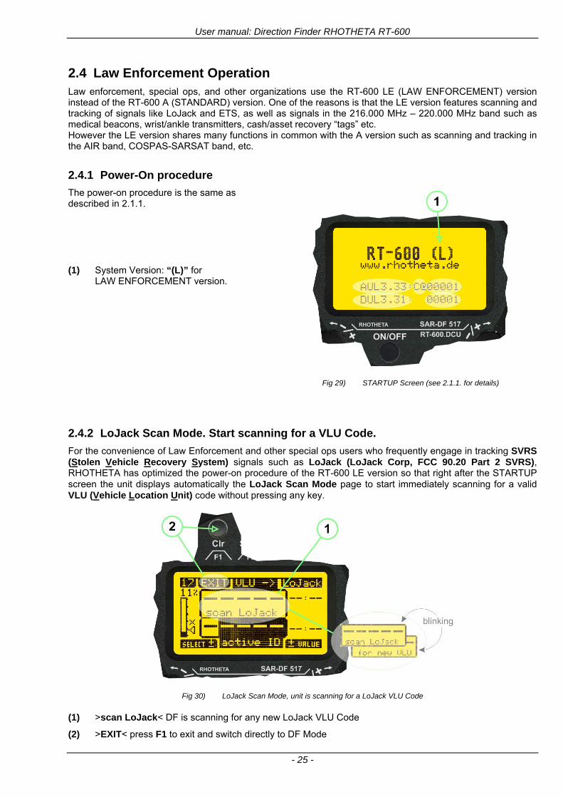
User manual Direction Finder RHOTHETA RT-600
- 25 -
24 Law Enforcement Operation Law enforcement special ops and other organizations use the RT-600 LE (LAW ENFORCEMENT) version instead of the RT-600 A (STANDARD) version One of the reasons is that the LE version features scanning and tracking of signals like LoJack and ETS as well as signals in the 216000 MHz ndash 220000 MHz band such as medical beacons wristankle transmitters cashasset recovery ldquotagsrdquo etc However the LE version shares many functions in common with the A version such as scanning and tracking in the AIR band COSPAS-SARSAT band etc
241 Power-On procedure
The power-on procedure is the same as described in 211
(1) System Version ldquo(L)rdquo for LAW ENFORCEMENT version
Fig 29) STARTUP Screen (see 211 for details)
242 LoJack Scan Mode Start scanning for a VLU Code
For the convenience of Law Enforcement and other special ops users who frequently engage in tracking SVRS (Stolen Vehicle Recovery System) signals such as LoJack (LoJack Corp FCC 9020 Part 2 SVRS) RHOTHETA has optimized the power-on procedure of the RT-600 LE version so that right after the STARTUP screen the unit displays automatically the LoJack Scan Mode page to start immediately scanning for a valid VLU (Vehicle Location Unit) code without pressing any key
Fig 30) LoJack Scan Mode unit is scanning for a LoJack VLU Code
(1) gtscan LoJacklt DF is scanning for any new LoJack VLU Code
(2) gtEXITlt press F1 to exit and switch directly to DF Mode
User manual Direction Finder RHOTHETA RT-600
- 26 -
243 LoJack Scan Mode from any other page
While operating on any page other than the LoJack Scan page the user can switch directly to LoJack Scan Mode by pressing Hotkey F2 for 2 secs
(1) press Hotkey F2 for 2 secs to switch to the LoJack Scan page
Fig 31) Hotkey F2
User manual Direction Finder RHOTHETA RT-600
- 27 -
244 Manual activation of LoJack Scan Mode
(1) select the LoJack frequency (see also Frequency Selection Page)
(2) press F1 to switch back to the DF MODE
Fig 32) FRQ Selection Page FRQ = LoJack BAND = LoJack (164-174 MHz)
While in DF MODE with adjusted LoJack frequency the user can switch directly to the LoJack Scan by pressing gtF1lt ldquoSCANrdquo
(1) press F1 SCAN to switch to the LoJack Scan page
(2) still no LoJack ID filter used (ID=off) all transmissions are received on the active frequency as example also unwanted tower pulses
Fig 33) DF Mode with LoJack filter OFF
User manual Direction Finder RHOTHETA RT-600
- 28 -
245 Receiving and accepting a new VLU Code
While in LoJack Scan Mode waiting for a VLU Code if a new VLU Code is displayed the user can accept it and switch directly to DF Mode by pressing F2
(1) a new LoJack VLU Code (0001A) has been received
(2) press F2 to accept the new VLU Code (0001A) and switch to DF MODE page with the LoJack filter activated to track only 0001A
Fig 34) LoJack Scan Mode with new VLU Code received
246 Entering a new VLU Code manually
While in LoJack Scan Mode the user can enter a LoJack VLU code also manually
(1 2 3) use the SELECTplusmn and plusmnVALUE knobs to enter a new LoJack VLU Code active ID (0001A)
(4) Press F1 to accept the new VLU Code and switch to DF Mode with the LoJack filter ON to track only 0001A
Fig 35) LoJack Scan Mode with new VLU Code entered manually
User manual Direction Finder RHOTHETA RT-600
- 29 -
247 Tracking one VLU Code while monitoring new VLU Codes
While on DF Mode and tracking a VLU Code (0001A) the user can turn the LoJack switch OFF with F2 also the user can start scanning all VLUs again with F1
0001A is displayed as the active VLU Code filter function is ON only 0001A is tracked
Monitoring of other VLU Codes is active in the background
(1) Press F1 to switch to the LoJack Scan Mode to scan for new VLU Codes
(2) Press F2 to switch LoJack filter OFF
Fig 36) DF Mode with active VLU Code and LoJack filter ON
248 Tracking one VLU Code and receiving a new VLU Code
While on DF MODE page and tracking VLU Code (0001A) in the background a new VLU Code is received and decoded (G2HC7)
(1) The new VLU Code is announced (NEW G2HC7)
(2) Press F1 to switch to LoJack Scan Mode to see the arrival time of G2HC7 and the possibility to change bearing to this new G2HC7
Fig 37) DF Mode with active VLU Code and announcement of new VLU Code
User manual Direction Finder RHOTHETA RT-600
- 30 -
249 Switching to a new VLU Code
While on the LoJack Scan Page tracking one VLU Code (0001A) and notified of a new VLU Code (G2HC7)
(1) press F1 to continue tracking 0001A
(2) press F2 to start tracking G2HC7
(3) Time elapsed since G2HC7 was last received
(4) Time elapsed since 0001A was last received
If F1 is pressed for 2 sec the indicated VLU Code (G2HC7) and ID (0001A) are deleted
Fig 38) LoJack Scan Page with one active VLU Code and one new VLU Code
2410 ldquoBlockingrdquo function of one LoJack VLU Code
The LoJack scan page can also be used to ldquoblockrdquo one unwanted LoJack VLU ID signal by separating the adjusted active ID from any other received LoJack VLU signal This is done by muting the audio (see example below) when a LoJack signal with VLU code ldquo0001Ardquo is received gtgt Any new VLU Code (active LoJack signal) - except for 0001A ndash will be displayed on the top row and generate the audible beep tone
Fig 39) LoJack Scan Page with one active VLU Code and audio OFF
Tip ldquoBlockingrdquo is an important tool for practical missions As example a stolen vehicle with VLU ID ldquo0001Ardquo was tracked in the DF bearing mode The mission
is completed but the VLU is normally still transmitting With the settings above only new VLU signals except the now unwanted ldquo0001Ardquo are audible and displayed in the upper (scan LoJack hellip for new VLU) box
User manual Direction Finder RHOTHETA RT-600
- 31 -
2411 Tracking in the 216 to 220 MHz band
The RT-600 features scanning and bearing functionality in the 216000 MHz to 220000 MHz band The 216000 MHz ndash 220000 MHz band contains frequencies and signals used by special services and tracked by law enforcement special ops and similar organizations These are some of the frequencies and services in this band
CFR 90259 tx 216000 MHz to 220000 MHz
Low Power Radio Service (LPRS) tx 216000 MHz to 217000 MHz
Medical beacons Project Lifesaver tx wristankle tx 213000 MHz to 216000 MHz
ETS tx stolen cashasset recovery tx ldquobaitrdquordquotagrdquo tx 216000 MHz to 220000 MHz tx = transmitter(s) However any future or current user of the Rhotheta RT-600 must be aware that tracking signals on the frequencies listed above may be challenging and even frustrating due mostly to negative factors in some of the transmitters
bull Very low RF power output
bull Inefficient antennas
bull Battery-powered devices with a ldquolow batteryrdquo condition
bull Devices worn or located in conditions of poor RF propagation
bull Devices with channel spacing different than the one specified for the RT-600
These factors can make it very difficult for the DF to receive the signal andor display an accurate bearing Disclaimer For the reasons explained above and even though the RT-600 features top performance in its class RHOTHETA does not offer - and is not to be held responsible for - any guaranteed minimum range or distance to a transmitter in this band
25 Setup Edit Page System settings are displayed in the setup page The functions described in this section should be used by trained personal only
Fig 40) Accessing the Setup Page
The setup page can be accessed by holding down the gtCLRlt (1) and gtREPlt (2) buttons simultaneously and in the same time performing a left-hand turn on the gtPagelt rotary switch (3)
User manual Direction Finder RHOTHETA RT-600
- 32 -
Fig 41) Setup Page
(1) gtStorelt push-button must be pressed in parallel if a value of a setting shall be modified If a value can
be modified the background stops to blink
(2) gtSelectlt rotary switch used to scroll through the menu options The value of the actually activated menu option is high-lighted with dark background and blinking
(3) gtValuelt rotary switch used to change values in menu options (gtStorelt (1) has to be pressed in parallel if a value shall be modified)
(4) gtSN-Ratiolt menu option representing the necessary Signal-To-Noise-Ratio (Difference between signal and noise level) used as criterion for the automatic squelch function Please refer to the chapter ldquoSquelch Operationrdquo for details Default value is 60 dB
(5) gtMounting Positionlt menu option to select Top- or Bottom-Mounting of the DF antenna In case of rooftop installation (eg on land vehicles) ldquoToprdquo shall be selected In case of bottom-down (upside-down) installation (eg on a helicopter) ldquoBotrdquo shall be selected If this option is not selected correctly all bearing values will be mirror-inverted
(6) gtBearing Offsetlt menu option to include a constant offset correction to the bearing indication Bearing values in degrees will be changed according to the offset value
(7) gtMaximum External Dimming Voltage for Legendslt menu option which sets the upper limit of the dimming input voltage for the legends-panel Range=[15 hellip 28]V
(8) gtMinimum External Dimming Voltage for Legendslt menu option which sets the lower limit of the dimming input voltage for the legends-panel Range=[15 hellip 28]V
(9) gtPagelt rotary switch to be turned right-hand to go back to the Direction Finder page A left-hand turn on this rotary switch will show up an additional service page with debug information used for system checks
(10) gtExtended Seriallt It is possible to enable or disable the extended serial data protocol Only of interest if serial data is used by any connected control units like moving maps or computers For detailed information see (Serial interface data protocol (short description)gt at page 46) If there are compatibility problems with already existing older remote control software it is recommended to switch OFF the extended serial data protocol
User manual Direction Finder RHOTHETA RT-600
- 33 -
3 Error messages If an internal error of the device is recognized a corresponding flashing error message will be shown in the DF pages
Fig 42) Error Messages
(1) Error message including error code (in brackets)
(2) Short description of the indicated error
In case of coincidence of various errors the error with the highest priority will be displayed
Error message Error location Reason
Error (12) VOLTDU
Main voltage supply Main Voltage input too low ( 100 V)
Error (11) NO AU
Connection antenna display or Antenna Unit
No serial data (RS485) from Antenna Unit No or damaged connection between antenna and display or damaged antenna unit
Error (10) BAD AU
Connection antenna display
Incompatibility or bad data connection between display and antenna
Error (9) BAD RU
Remote Unit Incompatibility or bad data connection between display and external serial Remote Unit or PC
Error (8) VOLTAU
Antenna Unit Voltage supply at Antenna Unit too low ( 90 V) Main voltage supply too low or considerable drop of voltage between display and antenna
Error (7) BAD DCU
Connection Display Antenna
Incompatibility or bad data connection between antenna and display
Error (6) NO DCU
Connection Display Antenna
No serial data from Display Control Unit to Antenna Unit
Error (5) PLL ERR
antenna Error in synthesizer-oscillator of receiver in Antenna Unit
Error (4) FRQ+OFS
received transmitter Received frequency too high (more than 6 KHz error of transmitter)
Error (3) FRQ-OFS
received transmitter received frequency too low (more than 6 KHZ error of transmitter)
Error (2) DECODE
radio distance transmitter DF
Data Bits of decoded signal (COSPAS-SARSAT or LoJack) defective
Error (1) DATARNG
Incompatibility of data DCU AU
Protocol data bytes out of valid range
Error (0) NO REC
Antenna Unit receiver
Receiver board defective
User manual Direction Finder RHOTHETA RT-600
- 34 -
4 Installation
41 Antenna unit A convenient position of the monopole bearing antenna is crucial for good bearing results The antenna needs an effective ground connection to the body of the aircraft or to the roof of the vehicle If there is no metallic mounting surface available a metallic sheet or similar (net) with connection to ground has to be applied first between vehicle-body and antenna In this hatched area the antenna touches the body ofthe vehicleaircraft In order to obtain a good groundconnection the surface of the body should be bared(Measuring unit [mm])
8 x holes for mounting the antenna unit to the
vehicle aircraft
Fig 43) Antenna Mounting Drawing
User manual Direction Finder RHOTHETA RT-600
- 35 -
411 Influence of antenna location and environment on the bearing accuracy
Recommendations concerning the practical antenna unit location on helicopters and airplanes
The bearing accuracy of the direction finder antenna unit is severely influenced (comparable to an airspeed sensor) by the environment For comparison a perfect high quality speed sensor will not indicate the true airspeed if this sensor is interfered by strong turbulences The direction finder antenna unit acts as a sensor for electromagnetic waves In the near field of this antenna unit any conductive (eg metallic) obstacle will influence the incoming wave field and create reflections which decrease the bearing accuracy These are general physical limitations concerning all types of direction finder systems To achieve the best bearing results it should be considered that the antenna unit is installed as far away as possible from any other vertically polarized conductive structure If possible there should be no reflectors within an area of 2-3 feet around the antenna unit In this worst case example the direction finder will not work properly
Fig 44) Antenna Installed in a Bad Location
In this example the antenna unit is located too close to the cable cutter of the helicopter This cutter will produce strong reflections especially as the length is equal to Lambda4 within the VHF airband
User manual Direction Finder RHOTHETA RT-600
- 36 -
Examples of properly installed direction finder antenna units
Fig 45) Antenna Installed in Good Locations
User manual Direction Finder RHOTHETA RT-600
- 37 -
42 Display and Control Unit
The display control unit may be mounted into a front panel by the means of this mounting drawing
Fig 46) DCU Mounting Drawing
(all dimensions in [mm]) To install or uninstall the display control unit perform the following steps (1) Remove the cover caps of the four rotary switches
(2) Loose the screws visible below the position of the cover caps
(3) Remove the plastic button from the axis of the four rotary switches
(4) Mount dismount the display control unit
(5) Re-install the plastic buttons on the axis of the four rotary switches
(6) Fix the screws so that the plastic buttons are fixed on the axis
(7) Re-install the cover caps on the four rotary switches
User manual Direction Finder RHOTHETA RT-600
- 38 -
43 System Interconnect Wiring Diagram (Also refer to chapter ldquoTechnical Datardquo for details)
Fig 47) System Interconnect Wiring Diagram
6-pol Amphenol plug femalePTG06SE10-6S(SQ)
max length of cable 20 m 9-pol Sub-D plug (femalemale)
User manual Direction Finder RHOTHETA RT-600
- 39 -
5 Technical Data
51 Electric features
Method of bearing Doppler-principle (3 kHz rotational frequency right left rotation)
Bearing accuracy1 plusmn 5deg RMS
Internal resolution 1deg
Bearing Sensitivity VHF AirEmergency le 25 μVm (typical)
VHF Marine le 25 μVm (typical)
UHF Emergency and ETS le 4 μVm (typical)
COSPAS-SARSAT le 4 μVm (typical)
LoJack Decoding (50 Message Error Rate) and bearing le 5 μVm (typical)
Frequency stability plusmn 20 ppm (Δff = plusmn210-6)
Reception frequencies
SAR version (Standard)
Frequency Options
VHF Emergency Band 118000 to 124000 MHz (833 kHz steps AM)
VHF Marine Band 154000 to 163000 MHz ( 500 kHz steps FM) (channel 16 selectable via channel no)
UHF Emergency Band 240000 to 246000 MHz (2500 kHz steps AM)
UHF FM Band 406100 to 410000 MHz ( 500 kHz steps FM)
COSPAS-SARSAT 400000 to 406092 MHz Including 406022 to 406076 MHz (Channel A S)
F1 VHF Air Band 118000 to 136992 MHz
F2 extended VHF Marine Band 137000 to 224995 MHz
F3 extended UHF Air Band 225000 to 399975 MHz
F4 additional UHF FM Band 406100 to 470000 MHz
Reception frequencies
LAW Enforcement version
Frequency Options
VHF Emergency Band 118000 to 124000 MHz (833 kHz steps AM)
VHF Marine Band 154000 to 163000 MHz (500 kHz steps FM) (channel 16 selectable via channel no)
LoJack 164000 to 174000 MHz (125 kHz steps FM)
ETS 216000 to 220000 MHz (10125 kHz AM)
COSPAS-SARSAT 400000 to 406092 MHz Including 406022 to 406076 MHz (Channel A S)
F1VHF Air Band 118000 to 136992 MHz
F2 extended VHF Marine Band 137000 to 163000 MHz
COSPAS-SARSAT fast scan mode
Full automatic detection of any active COSPAS-SARSAT channel A to S within 400 ms
COSPAS-SARSAT decoding
Reception and decoding of COSPAS-SARSAT data signal (112 or 144 bit) specified according to COSPAS-SARSAT
LoJack decoding Selectable LoJack ID display and selective active filtering
Special scanning modes
complete maritime ship band scanning within 3 s (channel 01 hellip 88 also frequencies between 2 channels are included)
1With undisturbed wave field and sufficient field strength Measuring by changing the angle of incidence with the antenna rotating on a revolving table in order to eliminate environmental influences on the results No modulation
User manual Direction Finder RHOTHETA RT-600
- 40 -
Bearable modulation A3E F3E A3X (ELT-modulation) F1D G2D COSPAS-SARSAT Bearing largely independent of modulation
Polarization Vertical
Polarization error 5deg at 60deg field vector rotation
Garbling cone Ca 30deg to the vertical
Time of response2 50 ms (with sufficient reception field strength)
LC-graphic display 128 x 64 pixels supertwist transflective extended range of temperature dark-blue display on yellow-green background background light Freely adjustable (exponential) dimming of brightness
NVG cockpit design Fully compatible NVIS Green B display Control Unit optional
Operating voltage 275 V nominal 12 V to 35 V DC
Current consumption LCD-background light Off max 500 mA (12 V DC) max 250 mA (24 V DC)
LCD-background light 100 max 750 mA (12 V DC) max 350 mA (24 V DC)
LCD-background light 100 max 900 mA (12 V DC) with NVG Option max 400 mA (24 V DC)
Audio out For external speaker approx 2 W (4 Ω)
Serial data interface Serial interface RS-232 (9600 baud 8 data bits 1 stop bit no parity)
2Very weak signals can considerably increase the time of response
User manual Direction Finder RHOTHETA RT-600
- 41 -
52 Interface External connections (optional at Sub-D 9-pol Male connector)
Dimming
Pin 8
external voltage input for variable dimming of legends
(optional)
Analog input signal for variable control of the legends illumination Input voltage range is freely adjustable in the range of 15 hellip 28 V in the setup menu Refer to chapter ldquoSetup Pagerdquo Default setting 8 hellip28 V (8 V = Off 28 V = max dimming for legends)
Input Impedance gt 50 k
Pin 6 night status line for LCD
dimming (optional)
Low-active (as example switch to ground) At input voltage lt 25 VDC the LCD dimming operates in nightNVG mode Maximum brightness ca 4 of daydefault mode brightness
Input Impedance gt 50 k
Pin 4 NVG status line for LCD
dimming (optional)
Low-active (as example switch to ground) At input voltage lt 25 VDC the LCD dimming operates in nightNVG mode Maximum brightness ca 4 of daydefault mode brightness
Input Impedance gt 50 k
AudioLF
Pin 7 Audio output signal
AC coupled voltage source with very low inner resistance Maximum output voltage ca 8 VPP = 283V RMS at maximum Volume Maximum output power ca 2 W with 4 speaker
If a headphone is connected ([32hellip600] 100mW) we recommend using a resistor (18 025 W) between audio output and headphone to prevent damage of the headphone
Serial interface RS232 (9600 baud 8 data bits 1 stop bit no parity)
Pin 3 TXD Serial output (ca plusmn10 V)
Pin 2 RXD Serial input (ca plusmn10 V)
User manual Direction Finder RHOTHETA RT-600
- 42 -
53 Mechanical features
Temperature range
Display Control Unit permissible operating temperature3 -20 degC +60 degC permissible storage temperature -30 degC +80 degC
Antenna Unit permissible operating temperature3 -40 degC +60 degC permissible storage temperature -55 degC +80 degC
Protective system Antenna Unit IP 67
Weights Display Control Unit 250 g Antenna Unit 2000 g
Dimensions Display Control Unit 82 mm x 82 mm x 43 mm (width x height x depth) Antenna Unit 270 mm x 185 mm
Fig 48) DCU Mechanical Drawing (all dimensions in [mm])
3 For temperatures lower than ndash10deg C a warm-up period of 15 min should be allowed
User manual Direction Finder RHOTHETA RT-600
- 43 -
Fig 49) AU Mechanical Drawing (all dimensions in [mm])
User manual Direction Finder RHOTHETA RT-600
- 44 -
6 Appendix
61 Frequency Ranges
User manual Direction Finder RHOTHETA RT-600
- 45 -
62 Frequencies of channels on maritime band (only for standard [A] version) Frequency-range of the RT-600 in the maritime band 156000 MHz 162025 MHz
Channel No frequency (ship - station) Frequency (coast - station)
1 156050 MHz 160650 MHz 2 156100 MHz 160700 MHz 3 156150 MHz 160750 MHz 4 156200 MHz 160800 MHz 5 156250 MHz 160850 MHz 6 156300 MHz 160900 MHz 7 156350 MHz 160950 MHz 8 156400 MHz 9 156450 MHz
10 156500 MHz 11 156550 MHz 12 156600 MHz 13 156650 MHz 14 156700 MHz 15 156750 MHz 16 156800 MHz 17 156850 MHz 18 156900 MHz 161500 MHz 19 156950 MHz 161550 MHz 20 157000 MHz 161600 MHz 21 157050 MHz 161650 MHz 22 157100 MHz 161700 MHz 23 157150 MHz 161750 MHz 24 157200 MHz 161800 MHz 25 157250 MHz 161850 MHz 26 157300 MHz 161900 MHz 27 157350 MHz 161950 MHz 28 157400 MHz 162000 MHz 60 156025 MHz 160625 MHz 61 156075 MHz 160675 MHz 62 156125 MHz 160725 MHz 63 156175 MHz 160775 MHz 64 156225 MHz 160825 MHz 65 156275 MHz 160875 MHz 66 156325 MHz 160925 MHz 67 156375 MHz 68 156425 MHz 69 156475 MHz 70 156525 MHz 71 156575 MHz 72 156625 MHz 73 156675 MHz 74 156725 MHz 75 156775 MHz 76 156825 MHz 77 156875 MHz 78 156925 MHz 161525 MHz 79 156975 MHz 161575 MHz 80 157025 MHz 161625 MHz 81 157075 MHz 161675 MHz 82 157125 MHz 161725 MHz 83 157175 MHz 161775 MHz 84 157225 MHz 161825 MHz 85 157275 MHz 161875 MHz 86 157325 MHz 161925 MHz 87 157375 MHz 161975 MHz 88 157425 MHz 162025 MHz
User manual Direction Finder RHOTHETA RT-600
- 46 -
63 Serial interface data protocol (short description)
631 General
Interface parameters RS232 9600 Baud 8 databits 1 stopbit no parity LSB sent first Timing of serial data For accurate use of the serial data (even for the optional serial input commands) the correct timing is mandatory The DCU (Display Control Unit) sends out via the RS-232 Pins (see 43 System Interconnect Wiring Diagram page 38) cyclic and autonomous every approx 250300 ms a binary data stream which contains all relevant DF-bearing information The output data contains one or two blocks of binary data (see next picture with accordingly description) The optional serial input is only used if changes (as example frequency change) are done by additional remote control units
Fig 50) Timing of serial data
Serial standard output
This output data is always available and contains all relevant DF-bearing data For detailed content see page 47
Optional extended serial output
This data contains some additional information like as example CospasSarsat or LoJack decoding and ID data For detailed content see page 50 The data is only available with DCU Software [Rev ge 320] and if this optional data block is configured as ON = enabled (see Setup Edit Page point (10) )
Even to avoid compatibility problems with already existing older remote control software it is possible to disable switch off this additional data block (see Setup Edit Page point (10) )
Optional serial input
Only used for optional commands to control DCU parameters If as example the direction finder frequency is changed remotely there is send to the DCU one time this data block with the new frequency For detailed content see page 52
User manual Direction Finder RHOTHETA RT-600
- 47 -
632 Serial standard output (protocol description)
Specification serial standard output
The binary data stream with a length of 39 bytes starts with a header byte (value = hex 0xA0 as ID for DF Mode) The next bytes contain different values for status bearing information and also service The last byte is used for data stream checksum control Remark This is a binary data protocol So every byte value from 0dec hellip 255dec (0x00 hellip 0xFF) is possible Because of this it is not allowed to realize a start byte detection by the content (0xA0) The idle line detection is recommended for detection the end of message Register of databytes (for details see next page)
byte no
[0] Header = 0xA0 Id for DF Mode
[1] Number = 39 = bytes in the complete message (including header and checksumbyte)
[2] Status (1) HSB [x|x|x|x|x|x|x|x] LSB | | | | | | | --gt (0) Receiving | | | | | | ----gt (1) Squelch controlled by AU (X) | | | | | ------gt (2) Permission RL Calibration | | | | --------gt (3) Line Night | | | ----------gt (4) Line NVG | | ------------gt (5) Dimming External | --------------gt (6) Autosquelch Active ----------------gt (7) 0=Standard Version 1=LE Version
[3] Status (2) HSB [x|x|x|x|x|x|x|x] LSB | ----------------gt (7) 0=Standard 1=extended serial dataprotocol = ONactive
[45] Error (Bits[120])
[6] Actual DCU Page
[7] Volume [0hellip100]
[811] Frequency [Hz]
[12] Active Band
[13] Actual Squelchlevel [0hellip60]
[14] Audio-Line amp_NF_Test Output
[15] (Not used)
[1617] Voltage_DCU ([0hellip335]=[0 hellip 335]V
[1819] Voltage_AU ([0hellip255]=[0 hellip 255]V
[20] Temperature_AU [-68hellip+127]degC
[21] Frequency Offset [-99hellip+99]
[2225] ServiceTest values (mode dependent test values for service only)
26 (Not used reserved)
[27] Level [0hellip100]
[2829] Bearing Averaged [0hellip359]deg relative
[3031] Bearing Live_Min [0hellip359]deg relative
[3233] Bearing Live_Max [0hellip359]deg relative
[34] Test Value PS-RAM Right Rotation[0hellip178] (for service only)
[35] Test Value PS-RAM Left Rotation [0hellip178] (for service only)
[3637] (Not used reserved)
[38] Checksum is the 2rsquos complement of the modulo-256 sum of all bytes without checksum-byte [0n-1]
User manual Direction Finder RHOTHETA RT-600
- 48 -
Detailed Description of important values for practical use
Status byte [2] Receiving Bit 0 of this value (LSB) indicates signal receiving Bit 0 = 0 then no signal is received and so on no bearing is available Bit 0 = 1 then bearing is possible Bit 1 if(1) then Squelch is controlled by AU (active at modes CospasSarsat Decode CospasSarsat Scanning LoJack with Filter=ID only)
Error bytes [4hellip5] 16 bit value each set bit corresponds to the error no (Refer to the chapter Error messages) Example - 0x0000 No error - 0x0800 Bit No 11 Set ( = No AU Error)
Actual DCU Page byte [6] indicates actual operating mode of DCU 0 = Standard bearing page 1 = Frequency memory page 2 = CospasSarsat decoding page 3 = LoJack decoding page (ID edit)
Frequency bytes [8hellip11] 32 bit value actual adjusted frequency [Hz] Example - 0x073DF160 1215000000 121500 MHz
Active Band Standard Version [A] 0=VHF Airband 1=VHF Marineband sea 2=VHF Marineband coast 3=UHV Airband 4=CospasSarsat LE Version [L] 0=VHF Airband 1=LoJack 2=Lifesaver 3=ETS 4=CospasSarsat
Actual Squelchlevel byte [13] Range [0hellip60] without signal the actual squelchlevel should always be adjusted a little bit over the noise level (Refer to the chapter Squelch operation)
Level byte [27] Range [099] actual receiving level (without signal this value is equal to the noise level) If a signal is received then this value corresponds to the signal strength of this signal
Relative Bearing averaged byte [2829] 16 bit value Range [0hellip359 0xFFFF] if the value = 0xFFFF then no valid bearing is available otherwise this value contains the actual averaged bearing information in Deg [0deg359deg] Example - 0X0114 276deg bearing (= left side oriented to heading)
Bearing Live MinMax byte[3031] amp [3233] - 16 bit values Range [0hellip359 0xFFFF] Only for signal quality or additional information ndash NOT recommended for bearing indication The relative live bearing field contains the maxmin bearing in degrees without averaging The relative live bearing reacts faster than the normal relative bearing but it has not the precision of the averaged bearing The MinMax Bearing Values are calculated within a time period of approx 250 ms If they are very close together (for example ldquo124rdquo and ldquo128rdquo degrees) then the signal quality is quite good A wide span of the minmax values (for example ldquo97rdquo and ldquo162rdquo) shows very noisy but nevertheless bearable signal quality
User manual Direction Finder RHOTHETA RT-600
- 49 -
633 DCU Info output (protocol description)
Specification DCU Info output
Remark This protocol is only available while the SetupEdit page is activated at the DCU
byte no
[0] Header = 0xAF Id for DCU Info Mode
[1] Number = 39 = bytes in the complete message (including header and checksumbyte)
[2]
(see standard output) [3]
[45]
[621] Info String of 15 byteschars the string contains Information about Unit Variant Software Version and Serial No
Example Byte [318] =
|--AU ID---||Var-||---Software Version---| |-------------- Serial No---------------| [0x44][0x55][0x41][0x33][0x2E][0x33][0x30][0x3A][0x20][0x20][0x30][0x31][0x32][0x33][0x34][0x00] rsquoDrsquo rsquoUrsquo rsquoArsquo rsquo3rsquo rsquorsquo rsquo3rsquo rsquo0rsquo rsquorsquo rsquo rsquo rsquo rsquo rsquo0rsquo rsquo1rsquo rsquo2rsquo rsquo3rsquo rsquo4rsquo rsquoENDrsquo | | | | __________________ | | ________________________ | n n n | | n n n n n | (Software Version) | | (Serial No) | gt rsquoArsquo = Standard Variant gt rsquoLrsquo = Law Enforcement Variant
User manual Direction Finder RHOTHETA RT-600
- 50 -
634 Optional extended serial output (protocol description)
The data content depends on the actual mode of the direction finder To get special data the direction finder has first to be switched to the equivalent mode
COSPAS-SARSAT Decoding data
This data is only available and valid if Display Control Unit with actual software Rev ge 320 (see Power-On procedure page 10) Configuration of Extended serial = ON (see Setup Edit Page point (10) ) Direction Finder COSPAS-SARSAT decoding mode is activated by selecting the corresponding page
(see COSPAS-SARSAT Decode Window page 20 and page 21) and so on Header (byte 0 of data) = 0x91
A valid COSPAS-SARSAT decoding data protocol is always marked by the first data byte (header = 0x91) Always after receiving and decoding of a valid COSPAS-SARSAT pulse the complete data protocol with 33 bytes is send out one time
Byte No
[0] Header = 0x91 (Identification for CPSarsat decoding mode)
[1] Number of bytes - 7 if no decoded pulse is available - 33 if new pulse was received and is available
[2] Error
[3] Bit[0] - 0 =gt No new 406 MSG (decoded data) available - 1 =gt New valid 406 MSG available (Sync amp Frame Ok) Check Error Status for Bit-Errors
Bit[61] AutoSquelch Level valid range [060] ( decimal)
Bit[7] = 1 Squelch controlled by AU
[4] Signallevel of received signal valid range [099] ( decimal)
[5] Voltage of Antenna Unit Power Supply input valid range [80255] (decimal = 80 255 V DC)
[6] Temperature inside Antenna Unit valid range [-50+100] (degC signed byte value)
The following databytes are only available if a correct CPSarsat puls gets received and decoded with correct checksum
[724] 18 x Databytes complete orginal CPSarsat 406 decoded message (144 bit)
Databyte Nr [ Byte 7 ] [ Byte 8 ] [Byte9 Byte24] 406 MSG Bit Nr [1 2 3 4 5 6 7 8] [9 10 11 12 13 14 15 16] [17 144]
[25] SN-Flag valid values 0x53=rsquoSrsquo 0x4E=rsquoNrsquo 0x2D=rsquo-rsquo if no GPS data available
GPS-Position Latitude
[26] Deg valid values [090] (decimal Deg) 0xFF if no GPS data available
[27] Min valid values [059] (decimal Deg) 0xFF if no GPS data available
[28] Sec valid values [059] (decimal Deg) 0xFF if no GPS data available
[29] WE-Flag valid values 0x57=rsquoWrsquo 0x45=rsquoErsquo 0x2D=rsquo-rsquo if no GPS data available
GPS-Position Longitude
[30] Deg valid values [0180] (decimal Deg) 0xFF if no GPS data available
[31] Min valid values [059] (decimal Deg) 0xFF if no GPS data available
[32] Sec valid values [059] (decimal Deg) 0xFF if no GPS data available
User manual Direction Finder RHOTHETA RT-600
- 51 -
LoJack ID data
This data is only available and valid if Display Control Unit with actual software Rev ge 320 (see Power-On procedure page 10) Direction Finder of variant [L] Law Enforcement Configuration of Extended serial = ON (see Setup Edit Page point (10) ) Direction Finder is working with active LoJack gtID Filterlt Header (byte 0 of data) = 0x93 or 0x94
Valid LoJack ID decoding data is always marked by the first data byte (header = 0x93 or 0x94)
Byte No
[0] Header = 0x93 LoJack ID editing sub-page is selected Filter = VLU all valid and received LoJack pulses are indicated = 0x94 Lojack Decode amp DF Mode with active Filter = ID
[1] Number of bytes in the complete data stream - decimal 26 = default value
[2] Nonrelevant
[3] Bit[0] Receiving OnOff - 0 =gt No Receiving no bearing - 1 =gt new LoJack pulse received
[412] Nonrelevant
[1317] Lojack ID
Replay Code 5 x ASCII Chars ldquoNo BIOZrdquo set
Example ASCII = ldquo000R1rdquo
18 Receiver Level Out Max [099]
19
LoJack Decoder Status [07] - 0 Off - 1 Wait for Preamble - 2 Preamble Ok - 3 FlagPattern Ok - 4 Data BitError gt 1 - 5 Data Ok (No VLU) - 6 VLU Ok - 7 ID Ok (Filter=IDONLY)
[2025] Nonrelevant
Remark Only if byte no [3] bit [0] gets ldquo1rdquo (Receiving On) then an active LoJack pulse is received and so on the corresponding LoJack ID valid otherwise the LoJack ID only shows the actual adjusted LoJack Filter ID of the direction finder
User manual Direction Finder RHOTHETA RT-600
- 52 -
635 Optional serial input (protocol description)
Specification serial input (optional)
The serial input is normally used for service and maintenance only Nevertheless it is possible via this interface to remote control the actual frequency and the squelchlevel of the DF system If a valid data stream is send to the DF then the actual frequency selection at the DCU is switched to Block2 AUX0 At this memory channel the new frequency is stored and used automatically (Refer to the chapter Frequency Selection Page) If the frequency is changed (by one valid data stream) no more serial input is necessary The actual frequency can be changed again at any time by manual operation at the DCU The timing of serial input (if used) is strictly fixed The optional serial input has to take place directly after a complete serial output (max 50 ms delay time) If a new changed frequency is commanded to the DCU via this serial input interface it can take up to 1 sec of time until this new frequency is ready for operationbearing It is strictly not recommended to use the frequency remote control for any scan mode The frequency control has to be used for static frequency change only Register of databytes
byte no
[0] Header 0xC0
[1] Number of bytes in the complete message (including header and checksumbyte)
[23] (not used for normal operation any byte values allowed)
[4] Volume [0100]
[58] Frequency [Hz] (frequency is rounded to the according grid automatically)
Valid Range for Standard Version Valid Range for LE Version
118000000 hellip 123000000 [Hz] 8333 kHz 118000000 hellip 123000000 [Hz] 8333 kHz
156050000 hellip 162025000 [Hz] 5000 kHz 164000000 hellip 174000000 [Hz] 8333 kHz
201000000 hellip 215995000 [Hz] 5000 kHz
240000000 hellip 246000000 [Hz] 8333 kHz 216000000 hellip 218995000 [Hz] 12500 kHz219000000 hellip 220000000 [Hz] 10000 kHz
400000000 hellip 410000000 [Hz] 8333 kHz 400000000 hellip 410000000 [Hz] 8333 kHz
[9] Squelchlevel Manual = [0hellip60] Autosql= [ -1] Warning use only for pulsed signals (as example CpSarsat LoJack)
[10] (not used for normal operation any byte values allowed)
[11] Internal Dimming [0100]
[12] Checksum is the 2rsquos complement of the modulo-256 sum of all bytes without checksum-byte [0n-1]
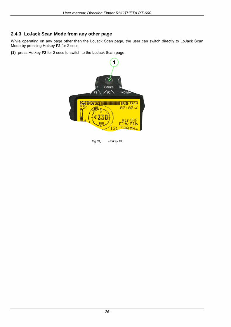
User manual Direction Finder RHOTHETA RT-600
- 26 -
243 LoJack Scan Mode from any other page
While operating on any page other than the LoJack Scan page the user can switch directly to LoJack Scan Mode by pressing Hotkey F2 for 2 secs
(1) press Hotkey F2 for 2 secs to switch to the LoJack Scan page
Fig 31) Hotkey F2
User manual Direction Finder RHOTHETA RT-600
- 27 -
244 Manual activation of LoJack Scan Mode
(1) select the LoJack frequency (see also Frequency Selection Page)
(2) press F1 to switch back to the DF MODE
Fig 32) FRQ Selection Page FRQ = LoJack BAND = LoJack (164-174 MHz)
While in DF MODE with adjusted LoJack frequency the user can switch directly to the LoJack Scan by pressing gtF1lt ldquoSCANrdquo
(1) press F1 SCAN to switch to the LoJack Scan page
(2) still no LoJack ID filter used (ID=off) all transmissions are received on the active frequency as example also unwanted tower pulses
Fig 33) DF Mode with LoJack filter OFF
User manual Direction Finder RHOTHETA RT-600
- 28 -
245 Receiving and accepting a new VLU Code
While in LoJack Scan Mode waiting for a VLU Code if a new VLU Code is displayed the user can accept it and switch directly to DF Mode by pressing F2
(1) a new LoJack VLU Code (0001A) has been received
(2) press F2 to accept the new VLU Code (0001A) and switch to DF MODE page with the LoJack filter activated to track only 0001A
Fig 34) LoJack Scan Mode with new VLU Code received
246 Entering a new VLU Code manually
While in LoJack Scan Mode the user can enter a LoJack VLU code also manually
(1 2 3) use the SELECTplusmn and plusmnVALUE knobs to enter a new LoJack VLU Code active ID (0001A)
(4) Press F1 to accept the new VLU Code and switch to DF Mode with the LoJack filter ON to track only 0001A
Fig 35) LoJack Scan Mode with new VLU Code entered manually
User manual Direction Finder RHOTHETA RT-600
- 29 -
247 Tracking one VLU Code while monitoring new VLU Codes
While on DF Mode and tracking a VLU Code (0001A) the user can turn the LoJack switch OFF with F2 also the user can start scanning all VLUs again with F1
0001A is displayed as the active VLU Code filter function is ON only 0001A is tracked
Monitoring of other VLU Codes is active in the background
(1) Press F1 to switch to the LoJack Scan Mode to scan for new VLU Codes
(2) Press F2 to switch LoJack filter OFF
Fig 36) DF Mode with active VLU Code and LoJack filter ON
248 Tracking one VLU Code and receiving a new VLU Code
While on DF MODE page and tracking VLU Code (0001A) in the background a new VLU Code is received and decoded (G2HC7)
(1) The new VLU Code is announced (NEW G2HC7)
(2) Press F1 to switch to LoJack Scan Mode to see the arrival time of G2HC7 and the possibility to change bearing to this new G2HC7
Fig 37) DF Mode with active VLU Code and announcement of new VLU Code
User manual Direction Finder RHOTHETA RT-600
- 30 -
249 Switching to a new VLU Code
While on the LoJack Scan Page tracking one VLU Code (0001A) and notified of a new VLU Code (G2HC7)
(1) press F1 to continue tracking 0001A
(2) press F2 to start tracking G2HC7
(3) Time elapsed since G2HC7 was last received
(4) Time elapsed since 0001A was last received
If F1 is pressed for 2 sec the indicated VLU Code (G2HC7) and ID (0001A) are deleted
Fig 38) LoJack Scan Page with one active VLU Code and one new VLU Code
2410 ldquoBlockingrdquo function of one LoJack VLU Code
The LoJack scan page can also be used to ldquoblockrdquo one unwanted LoJack VLU ID signal by separating the adjusted active ID from any other received LoJack VLU signal This is done by muting the audio (see example below) when a LoJack signal with VLU code ldquo0001Ardquo is received gtgt Any new VLU Code (active LoJack signal) - except for 0001A ndash will be displayed on the top row and generate the audible beep tone
Fig 39) LoJack Scan Page with one active VLU Code and audio OFF
Tip ldquoBlockingrdquo is an important tool for practical missions As example a stolen vehicle with VLU ID ldquo0001Ardquo was tracked in the DF bearing mode The mission
is completed but the VLU is normally still transmitting With the settings above only new VLU signals except the now unwanted ldquo0001Ardquo are audible and displayed in the upper (scan LoJack hellip for new VLU) box
User manual Direction Finder RHOTHETA RT-600
- 31 -
2411 Tracking in the 216 to 220 MHz band
The RT-600 features scanning and bearing functionality in the 216000 MHz to 220000 MHz band The 216000 MHz ndash 220000 MHz band contains frequencies and signals used by special services and tracked by law enforcement special ops and similar organizations These are some of the frequencies and services in this band
CFR 90259 tx 216000 MHz to 220000 MHz
Low Power Radio Service (LPRS) tx 216000 MHz to 217000 MHz
Medical beacons Project Lifesaver tx wristankle tx 213000 MHz to 216000 MHz
ETS tx stolen cashasset recovery tx ldquobaitrdquordquotagrdquo tx 216000 MHz to 220000 MHz tx = transmitter(s) However any future or current user of the Rhotheta RT-600 must be aware that tracking signals on the frequencies listed above may be challenging and even frustrating due mostly to negative factors in some of the transmitters
bull Very low RF power output
bull Inefficient antennas
bull Battery-powered devices with a ldquolow batteryrdquo condition
bull Devices worn or located in conditions of poor RF propagation
bull Devices with channel spacing different than the one specified for the RT-600
These factors can make it very difficult for the DF to receive the signal andor display an accurate bearing Disclaimer For the reasons explained above and even though the RT-600 features top performance in its class RHOTHETA does not offer - and is not to be held responsible for - any guaranteed minimum range or distance to a transmitter in this band
25 Setup Edit Page System settings are displayed in the setup page The functions described in this section should be used by trained personal only
Fig 40) Accessing the Setup Page
The setup page can be accessed by holding down the gtCLRlt (1) and gtREPlt (2) buttons simultaneously and in the same time performing a left-hand turn on the gtPagelt rotary switch (3)
User manual Direction Finder RHOTHETA RT-600
- 32 -
Fig 41) Setup Page
(1) gtStorelt push-button must be pressed in parallel if a value of a setting shall be modified If a value can
be modified the background stops to blink
(2) gtSelectlt rotary switch used to scroll through the menu options The value of the actually activated menu option is high-lighted with dark background and blinking
(3) gtValuelt rotary switch used to change values in menu options (gtStorelt (1) has to be pressed in parallel if a value shall be modified)
(4) gtSN-Ratiolt menu option representing the necessary Signal-To-Noise-Ratio (Difference between signal and noise level) used as criterion for the automatic squelch function Please refer to the chapter ldquoSquelch Operationrdquo for details Default value is 60 dB
(5) gtMounting Positionlt menu option to select Top- or Bottom-Mounting of the DF antenna In case of rooftop installation (eg on land vehicles) ldquoToprdquo shall be selected In case of bottom-down (upside-down) installation (eg on a helicopter) ldquoBotrdquo shall be selected If this option is not selected correctly all bearing values will be mirror-inverted
(6) gtBearing Offsetlt menu option to include a constant offset correction to the bearing indication Bearing values in degrees will be changed according to the offset value
(7) gtMaximum External Dimming Voltage for Legendslt menu option which sets the upper limit of the dimming input voltage for the legends-panel Range=[15 hellip 28]V
(8) gtMinimum External Dimming Voltage for Legendslt menu option which sets the lower limit of the dimming input voltage for the legends-panel Range=[15 hellip 28]V
(9) gtPagelt rotary switch to be turned right-hand to go back to the Direction Finder page A left-hand turn on this rotary switch will show up an additional service page with debug information used for system checks
(10) gtExtended Seriallt It is possible to enable or disable the extended serial data protocol Only of interest if serial data is used by any connected control units like moving maps or computers For detailed information see (Serial interface data protocol (short description)gt at page 46) If there are compatibility problems with already existing older remote control software it is recommended to switch OFF the extended serial data protocol
User manual Direction Finder RHOTHETA RT-600
- 33 -
3 Error messages If an internal error of the device is recognized a corresponding flashing error message will be shown in the DF pages
Fig 42) Error Messages
(1) Error message including error code (in brackets)
(2) Short description of the indicated error
In case of coincidence of various errors the error with the highest priority will be displayed
Error message Error location Reason
Error (12) VOLTDU
Main voltage supply Main Voltage input too low ( 100 V)
Error (11) NO AU
Connection antenna display or Antenna Unit
No serial data (RS485) from Antenna Unit No or damaged connection between antenna and display or damaged antenna unit
Error (10) BAD AU
Connection antenna display
Incompatibility or bad data connection between display and antenna
Error (9) BAD RU
Remote Unit Incompatibility or bad data connection between display and external serial Remote Unit or PC
Error (8) VOLTAU
Antenna Unit Voltage supply at Antenna Unit too low ( 90 V) Main voltage supply too low or considerable drop of voltage between display and antenna
Error (7) BAD DCU
Connection Display Antenna
Incompatibility or bad data connection between antenna and display
Error (6) NO DCU
Connection Display Antenna
No serial data from Display Control Unit to Antenna Unit
Error (5) PLL ERR
antenna Error in synthesizer-oscillator of receiver in Antenna Unit
Error (4) FRQ+OFS
received transmitter Received frequency too high (more than 6 KHz error of transmitter)
Error (3) FRQ-OFS
received transmitter received frequency too low (more than 6 KHZ error of transmitter)
Error (2) DECODE
radio distance transmitter DF
Data Bits of decoded signal (COSPAS-SARSAT or LoJack) defective
Error (1) DATARNG
Incompatibility of data DCU AU
Protocol data bytes out of valid range
Error (0) NO REC
Antenna Unit receiver
Receiver board defective
User manual Direction Finder RHOTHETA RT-600
- 34 -
4 Installation
41 Antenna unit A convenient position of the monopole bearing antenna is crucial for good bearing results The antenna needs an effective ground connection to the body of the aircraft or to the roof of the vehicle If there is no metallic mounting surface available a metallic sheet or similar (net) with connection to ground has to be applied first between vehicle-body and antenna In this hatched area the antenna touches the body ofthe vehicleaircraft In order to obtain a good groundconnection the surface of the body should be bared(Measuring unit [mm])
8 x holes for mounting the antenna unit to the
vehicle aircraft
Fig 43) Antenna Mounting Drawing
User manual Direction Finder RHOTHETA RT-600
- 35 -
411 Influence of antenna location and environment on the bearing accuracy
Recommendations concerning the practical antenna unit location on helicopters and airplanes
The bearing accuracy of the direction finder antenna unit is severely influenced (comparable to an airspeed sensor) by the environment For comparison a perfect high quality speed sensor will not indicate the true airspeed if this sensor is interfered by strong turbulences The direction finder antenna unit acts as a sensor for electromagnetic waves In the near field of this antenna unit any conductive (eg metallic) obstacle will influence the incoming wave field and create reflections which decrease the bearing accuracy These are general physical limitations concerning all types of direction finder systems To achieve the best bearing results it should be considered that the antenna unit is installed as far away as possible from any other vertically polarized conductive structure If possible there should be no reflectors within an area of 2-3 feet around the antenna unit In this worst case example the direction finder will not work properly
Fig 44) Antenna Installed in a Bad Location
In this example the antenna unit is located too close to the cable cutter of the helicopter This cutter will produce strong reflections especially as the length is equal to Lambda4 within the VHF airband
User manual Direction Finder RHOTHETA RT-600
- 36 -
Examples of properly installed direction finder antenna units
Fig 45) Antenna Installed in Good Locations
User manual Direction Finder RHOTHETA RT-600
- 37 -
42 Display and Control Unit
The display control unit may be mounted into a front panel by the means of this mounting drawing
Fig 46) DCU Mounting Drawing
(all dimensions in [mm]) To install or uninstall the display control unit perform the following steps (1) Remove the cover caps of the four rotary switches
(2) Loose the screws visible below the position of the cover caps
(3) Remove the plastic button from the axis of the four rotary switches
(4) Mount dismount the display control unit
(5) Re-install the plastic buttons on the axis of the four rotary switches
(6) Fix the screws so that the plastic buttons are fixed on the axis
(7) Re-install the cover caps on the four rotary switches
User manual Direction Finder RHOTHETA RT-600
- 38 -
43 System Interconnect Wiring Diagram (Also refer to chapter ldquoTechnical Datardquo for details)
Fig 47) System Interconnect Wiring Diagram
6-pol Amphenol plug femalePTG06SE10-6S(SQ)
max length of cable 20 m 9-pol Sub-D plug (femalemale)
User manual Direction Finder RHOTHETA RT-600
- 39 -
5 Technical Data
51 Electric features
Method of bearing Doppler-principle (3 kHz rotational frequency right left rotation)
Bearing accuracy1 plusmn 5deg RMS
Internal resolution 1deg
Bearing Sensitivity VHF AirEmergency le 25 μVm (typical)
VHF Marine le 25 μVm (typical)
UHF Emergency and ETS le 4 μVm (typical)
COSPAS-SARSAT le 4 μVm (typical)
LoJack Decoding (50 Message Error Rate) and bearing le 5 μVm (typical)
Frequency stability plusmn 20 ppm (Δff = plusmn210-6)
Reception frequencies
SAR version (Standard)
Frequency Options
VHF Emergency Band 118000 to 124000 MHz (833 kHz steps AM)
VHF Marine Band 154000 to 163000 MHz ( 500 kHz steps FM) (channel 16 selectable via channel no)
UHF Emergency Band 240000 to 246000 MHz (2500 kHz steps AM)
UHF FM Band 406100 to 410000 MHz ( 500 kHz steps FM)
COSPAS-SARSAT 400000 to 406092 MHz Including 406022 to 406076 MHz (Channel A S)
F1 VHF Air Band 118000 to 136992 MHz
F2 extended VHF Marine Band 137000 to 224995 MHz
F3 extended UHF Air Band 225000 to 399975 MHz
F4 additional UHF FM Band 406100 to 470000 MHz
Reception frequencies
LAW Enforcement version
Frequency Options
VHF Emergency Band 118000 to 124000 MHz (833 kHz steps AM)
VHF Marine Band 154000 to 163000 MHz (500 kHz steps FM) (channel 16 selectable via channel no)
LoJack 164000 to 174000 MHz (125 kHz steps FM)
ETS 216000 to 220000 MHz (10125 kHz AM)
COSPAS-SARSAT 400000 to 406092 MHz Including 406022 to 406076 MHz (Channel A S)
F1VHF Air Band 118000 to 136992 MHz
F2 extended VHF Marine Band 137000 to 163000 MHz
COSPAS-SARSAT fast scan mode
Full automatic detection of any active COSPAS-SARSAT channel A to S within 400 ms
COSPAS-SARSAT decoding
Reception and decoding of COSPAS-SARSAT data signal (112 or 144 bit) specified according to COSPAS-SARSAT
LoJack decoding Selectable LoJack ID display and selective active filtering
Special scanning modes
complete maritime ship band scanning within 3 s (channel 01 hellip 88 also frequencies between 2 channels are included)
1With undisturbed wave field and sufficient field strength Measuring by changing the angle of incidence with the antenna rotating on a revolving table in order to eliminate environmental influences on the results No modulation
User manual Direction Finder RHOTHETA RT-600
- 40 -
Bearable modulation A3E F3E A3X (ELT-modulation) F1D G2D COSPAS-SARSAT Bearing largely independent of modulation
Polarization Vertical
Polarization error 5deg at 60deg field vector rotation
Garbling cone Ca 30deg to the vertical
Time of response2 50 ms (with sufficient reception field strength)
LC-graphic display 128 x 64 pixels supertwist transflective extended range of temperature dark-blue display on yellow-green background background light Freely adjustable (exponential) dimming of brightness
NVG cockpit design Fully compatible NVIS Green B display Control Unit optional
Operating voltage 275 V nominal 12 V to 35 V DC
Current consumption LCD-background light Off max 500 mA (12 V DC) max 250 mA (24 V DC)
LCD-background light 100 max 750 mA (12 V DC) max 350 mA (24 V DC)
LCD-background light 100 max 900 mA (12 V DC) with NVG Option max 400 mA (24 V DC)
Audio out For external speaker approx 2 W (4 Ω)
Serial data interface Serial interface RS-232 (9600 baud 8 data bits 1 stop bit no parity)
2Very weak signals can considerably increase the time of response
User manual Direction Finder RHOTHETA RT-600
- 41 -
52 Interface External connections (optional at Sub-D 9-pol Male connector)
Dimming
Pin 8
external voltage input for variable dimming of legends
(optional)
Analog input signal for variable control of the legends illumination Input voltage range is freely adjustable in the range of 15 hellip 28 V in the setup menu Refer to chapter ldquoSetup Pagerdquo Default setting 8 hellip28 V (8 V = Off 28 V = max dimming for legends)
Input Impedance gt 50 k
Pin 6 night status line for LCD
dimming (optional)
Low-active (as example switch to ground) At input voltage lt 25 VDC the LCD dimming operates in nightNVG mode Maximum brightness ca 4 of daydefault mode brightness
Input Impedance gt 50 k
Pin 4 NVG status line for LCD
dimming (optional)
Low-active (as example switch to ground) At input voltage lt 25 VDC the LCD dimming operates in nightNVG mode Maximum brightness ca 4 of daydefault mode brightness
Input Impedance gt 50 k
AudioLF
Pin 7 Audio output signal
AC coupled voltage source with very low inner resistance Maximum output voltage ca 8 VPP = 283V RMS at maximum Volume Maximum output power ca 2 W with 4 speaker
If a headphone is connected ([32hellip600] 100mW) we recommend using a resistor (18 025 W) between audio output and headphone to prevent damage of the headphone
Serial interface RS232 (9600 baud 8 data bits 1 stop bit no parity)
Pin 3 TXD Serial output (ca plusmn10 V)
Pin 2 RXD Serial input (ca plusmn10 V)
User manual Direction Finder RHOTHETA RT-600
- 42 -
53 Mechanical features
Temperature range
Display Control Unit permissible operating temperature3 -20 degC +60 degC permissible storage temperature -30 degC +80 degC
Antenna Unit permissible operating temperature3 -40 degC +60 degC permissible storage temperature -55 degC +80 degC
Protective system Antenna Unit IP 67
Weights Display Control Unit 250 g Antenna Unit 2000 g
Dimensions Display Control Unit 82 mm x 82 mm x 43 mm (width x height x depth) Antenna Unit 270 mm x 185 mm
Fig 48) DCU Mechanical Drawing (all dimensions in [mm])
3 For temperatures lower than ndash10deg C a warm-up period of 15 min should be allowed
User manual Direction Finder RHOTHETA RT-600
- 43 -
Fig 49) AU Mechanical Drawing (all dimensions in [mm])
User manual Direction Finder RHOTHETA RT-600
- 44 -
6 Appendix
61 Frequency Ranges
User manual Direction Finder RHOTHETA RT-600
- 45 -
62 Frequencies of channels on maritime band (only for standard [A] version) Frequency-range of the RT-600 in the maritime band 156000 MHz 162025 MHz
Channel No frequency (ship - station) Frequency (coast - station)
1 156050 MHz 160650 MHz 2 156100 MHz 160700 MHz 3 156150 MHz 160750 MHz 4 156200 MHz 160800 MHz 5 156250 MHz 160850 MHz 6 156300 MHz 160900 MHz 7 156350 MHz 160950 MHz 8 156400 MHz 9 156450 MHz
10 156500 MHz 11 156550 MHz 12 156600 MHz 13 156650 MHz 14 156700 MHz 15 156750 MHz 16 156800 MHz 17 156850 MHz 18 156900 MHz 161500 MHz 19 156950 MHz 161550 MHz 20 157000 MHz 161600 MHz 21 157050 MHz 161650 MHz 22 157100 MHz 161700 MHz 23 157150 MHz 161750 MHz 24 157200 MHz 161800 MHz 25 157250 MHz 161850 MHz 26 157300 MHz 161900 MHz 27 157350 MHz 161950 MHz 28 157400 MHz 162000 MHz 60 156025 MHz 160625 MHz 61 156075 MHz 160675 MHz 62 156125 MHz 160725 MHz 63 156175 MHz 160775 MHz 64 156225 MHz 160825 MHz 65 156275 MHz 160875 MHz 66 156325 MHz 160925 MHz 67 156375 MHz 68 156425 MHz 69 156475 MHz 70 156525 MHz 71 156575 MHz 72 156625 MHz 73 156675 MHz 74 156725 MHz 75 156775 MHz 76 156825 MHz 77 156875 MHz 78 156925 MHz 161525 MHz 79 156975 MHz 161575 MHz 80 157025 MHz 161625 MHz 81 157075 MHz 161675 MHz 82 157125 MHz 161725 MHz 83 157175 MHz 161775 MHz 84 157225 MHz 161825 MHz 85 157275 MHz 161875 MHz 86 157325 MHz 161925 MHz 87 157375 MHz 161975 MHz 88 157425 MHz 162025 MHz
User manual Direction Finder RHOTHETA RT-600
- 46 -
63 Serial interface data protocol (short description)
631 General
Interface parameters RS232 9600 Baud 8 databits 1 stopbit no parity LSB sent first Timing of serial data For accurate use of the serial data (even for the optional serial input commands) the correct timing is mandatory The DCU (Display Control Unit) sends out via the RS-232 Pins (see 43 System Interconnect Wiring Diagram page 38) cyclic and autonomous every approx 250300 ms a binary data stream which contains all relevant DF-bearing information The output data contains one or two blocks of binary data (see next picture with accordingly description) The optional serial input is only used if changes (as example frequency change) are done by additional remote control units
Fig 50) Timing of serial data
Serial standard output
This output data is always available and contains all relevant DF-bearing data For detailed content see page 47
Optional extended serial output
This data contains some additional information like as example CospasSarsat or LoJack decoding and ID data For detailed content see page 50 The data is only available with DCU Software [Rev ge 320] and if this optional data block is configured as ON = enabled (see Setup Edit Page point (10) )
Even to avoid compatibility problems with already existing older remote control software it is possible to disable switch off this additional data block (see Setup Edit Page point (10) )
Optional serial input
Only used for optional commands to control DCU parameters If as example the direction finder frequency is changed remotely there is send to the DCU one time this data block with the new frequency For detailed content see page 52
User manual Direction Finder RHOTHETA RT-600
- 47 -
632 Serial standard output (protocol description)
Specification serial standard output
The binary data stream with a length of 39 bytes starts with a header byte (value = hex 0xA0 as ID for DF Mode) The next bytes contain different values for status bearing information and also service The last byte is used for data stream checksum control Remark This is a binary data protocol So every byte value from 0dec hellip 255dec (0x00 hellip 0xFF) is possible Because of this it is not allowed to realize a start byte detection by the content (0xA0) The idle line detection is recommended for detection the end of message Register of databytes (for details see next page)
byte no
[0] Header = 0xA0 Id for DF Mode
[1] Number = 39 = bytes in the complete message (including header and checksumbyte)
[2] Status (1) HSB [x|x|x|x|x|x|x|x] LSB | | | | | | | --gt (0) Receiving | | | | | | ----gt (1) Squelch controlled by AU (X) | | | | | ------gt (2) Permission RL Calibration | | | | --------gt (3) Line Night | | | ----------gt (4) Line NVG | | ------------gt (5) Dimming External | --------------gt (6) Autosquelch Active ----------------gt (7) 0=Standard Version 1=LE Version
[3] Status (2) HSB [x|x|x|x|x|x|x|x] LSB | ----------------gt (7) 0=Standard 1=extended serial dataprotocol = ONactive
[45] Error (Bits[120])
[6] Actual DCU Page
[7] Volume [0hellip100]
[811] Frequency [Hz]
[12] Active Band
[13] Actual Squelchlevel [0hellip60]
[14] Audio-Line amp_NF_Test Output
[15] (Not used)
[1617] Voltage_DCU ([0hellip335]=[0 hellip 335]V
[1819] Voltage_AU ([0hellip255]=[0 hellip 255]V
[20] Temperature_AU [-68hellip+127]degC
[21] Frequency Offset [-99hellip+99]
[2225] ServiceTest values (mode dependent test values for service only)
26 (Not used reserved)
[27] Level [0hellip100]
[2829] Bearing Averaged [0hellip359]deg relative
[3031] Bearing Live_Min [0hellip359]deg relative
[3233] Bearing Live_Max [0hellip359]deg relative
[34] Test Value PS-RAM Right Rotation[0hellip178] (for service only)
[35] Test Value PS-RAM Left Rotation [0hellip178] (for service only)
[3637] (Not used reserved)
[38] Checksum is the 2rsquos complement of the modulo-256 sum of all bytes without checksum-byte [0n-1]
User manual Direction Finder RHOTHETA RT-600
- 48 -
Detailed Description of important values for practical use
Status byte [2] Receiving Bit 0 of this value (LSB) indicates signal receiving Bit 0 = 0 then no signal is received and so on no bearing is available Bit 0 = 1 then bearing is possible Bit 1 if(1) then Squelch is controlled by AU (active at modes CospasSarsat Decode CospasSarsat Scanning LoJack with Filter=ID only)
Error bytes [4hellip5] 16 bit value each set bit corresponds to the error no (Refer to the chapter Error messages) Example - 0x0000 No error - 0x0800 Bit No 11 Set ( = No AU Error)
Actual DCU Page byte [6] indicates actual operating mode of DCU 0 = Standard bearing page 1 = Frequency memory page 2 = CospasSarsat decoding page 3 = LoJack decoding page (ID edit)
Frequency bytes [8hellip11] 32 bit value actual adjusted frequency [Hz] Example - 0x073DF160 1215000000 121500 MHz
Active Band Standard Version [A] 0=VHF Airband 1=VHF Marineband sea 2=VHF Marineband coast 3=UHV Airband 4=CospasSarsat LE Version [L] 0=VHF Airband 1=LoJack 2=Lifesaver 3=ETS 4=CospasSarsat
Actual Squelchlevel byte [13] Range [0hellip60] without signal the actual squelchlevel should always be adjusted a little bit over the noise level (Refer to the chapter Squelch operation)
Level byte [27] Range [099] actual receiving level (without signal this value is equal to the noise level) If a signal is received then this value corresponds to the signal strength of this signal
Relative Bearing averaged byte [2829] 16 bit value Range [0hellip359 0xFFFF] if the value = 0xFFFF then no valid bearing is available otherwise this value contains the actual averaged bearing information in Deg [0deg359deg] Example - 0X0114 276deg bearing (= left side oriented to heading)
Bearing Live MinMax byte[3031] amp [3233] - 16 bit values Range [0hellip359 0xFFFF] Only for signal quality or additional information ndash NOT recommended for bearing indication The relative live bearing field contains the maxmin bearing in degrees without averaging The relative live bearing reacts faster than the normal relative bearing but it has not the precision of the averaged bearing The MinMax Bearing Values are calculated within a time period of approx 250 ms If they are very close together (for example ldquo124rdquo and ldquo128rdquo degrees) then the signal quality is quite good A wide span of the minmax values (for example ldquo97rdquo and ldquo162rdquo) shows very noisy but nevertheless bearable signal quality
User manual Direction Finder RHOTHETA RT-600
- 49 -
633 DCU Info output (protocol description)
Specification DCU Info output
Remark This protocol is only available while the SetupEdit page is activated at the DCU
byte no
[0] Header = 0xAF Id for DCU Info Mode
[1] Number = 39 = bytes in the complete message (including header and checksumbyte)
[2]
(see standard output) [3]
[45]
[621] Info String of 15 byteschars the string contains Information about Unit Variant Software Version and Serial No
Example Byte [318] =
|--AU ID---||Var-||---Software Version---| |-------------- Serial No---------------| [0x44][0x55][0x41][0x33][0x2E][0x33][0x30][0x3A][0x20][0x20][0x30][0x31][0x32][0x33][0x34][0x00] rsquoDrsquo rsquoUrsquo rsquoArsquo rsquo3rsquo rsquorsquo rsquo3rsquo rsquo0rsquo rsquorsquo rsquo rsquo rsquo rsquo rsquo0rsquo rsquo1rsquo rsquo2rsquo rsquo3rsquo rsquo4rsquo rsquoENDrsquo | | | | __________________ | | ________________________ | n n n | | n n n n n | (Software Version) | | (Serial No) | gt rsquoArsquo = Standard Variant gt rsquoLrsquo = Law Enforcement Variant
User manual Direction Finder RHOTHETA RT-600
- 50 -
634 Optional extended serial output (protocol description)
The data content depends on the actual mode of the direction finder To get special data the direction finder has first to be switched to the equivalent mode
COSPAS-SARSAT Decoding data
This data is only available and valid if Display Control Unit with actual software Rev ge 320 (see Power-On procedure page 10) Configuration of Extended serial = ON (see Setup Edit Page point (10) ) Direction Finder COSPAS-SARSAT decoding mode is activated by selecting the corresponding page
(see COSPAS-SARSAT Decode Window page 20 and page 21) and so on Header (byte 0 of data) = 0x91
A valid COSPAS-SARSAT decoding data protocol is always marked by the first data byte (header = 0x91) Always after receiving and decoding of a valid COSPAS-SARSAT pulse the complete data protocol with 33 bytes is send out one time
Byte No
[0] Header = 0x91 (Identification for CPSarsat decoding mode)
[1] Number of bytes - 7 if no decoded pulse is available - 33 if new pulse was received and is available
[2] Error
[3] Bit[0] - 0 =gt No new 406 MSG (decoded data) available - 1 =gt New valid 406 MSG available (Sync amp Frame Ok) Check Error Status for Bit-Errors
Bit[61] AutoSquelch Level valid range [060] ( decimal)
Bit[7] = 1 Squelch controlled by AU
[4] Signallevel of received signal valid range [099] ( decimal)
[5] Voltage of Antenna Unit Power Supply input valid range [80255] (decimal = 80 255 V DC)
[6] Temperature inside Antenna Unit valid range [-50+100] (degC signed byte value)
The following databytes are only available if a correct CPSarsat puls gets received and decoded with correct checksum
[724] 18 x Databytes complete orginal CPSarsat 406 decoded message (144 bit)
Databyte Nr [ Byte 7 ] [ Byte 8 ] [Byte9 Byte24] 406 MSG Bit Nr [1 2 3 4 5 6 7 8] [9 10 11 12 13 14 15 16] [17 144]
[25] SN-Flag valid values 0x53=rsquoSrsquo 0x4E=rsquoNrsquo 0x2D=rsquo-rsquo if no GPS data available
GPS-Position Latitude
[26] Deg valid values [090] (decimal Deg) 0xFF if no GPS data available
[27] Min valid values [059] (decimal Deg) 0xFF if no GPS data available
[28] Sec valid values [059] (decimal Deg) 0xFF if no GPS data available
[29] WE-Flag valid values 0x57=rsquoWrsquo 0x45=rsquoErsquo 0x2D=rsquo-rsquo if no GPS data available
GPS-Position Longitude
[30] Deg valid values [0180] (decimal Deg) 0xFF if no GPS data available
[31] Min valid values [059] (decimal Deg) 0xFF if no GPS data available
[32] Sec valid values [059] (decimal Deg) 0xFF if no GPS data available
User manual Direction Finder RHOTHETA RT-600
- 51 -
LoJack ID data
This data is only available and valid if Display Control Unit with actual software Rev ge 320 (see Power-On procedure page 10) Direction Finder of variant [L] Law Enforcement Configuration of Extended serial = ON (see Setup Edit Page point (10) ) Direction Finder is working with active LoJack gtID Filterlt Header (byte 0 of data) = 0x93 or 0x94
Valid LoJack ID decoding data is always marked by the first data byte (header = 0x93 or 0x94)
Byte No
[0] Header = 0x93 LoJack ID editing sub-page is selected Filter = VLU all valid and received LoJack pulses are indicated = 0x94 Lojack Decode amp DF Mode with active Filter = ID
[1] Number of bytes in the complete data stream - decimal 26 = default value
[2] Nonrelevant
[3] Bit[0] Receiving OnOff - 0 =gt No Receiving no bearing - 1 =gt new LoJack pulse received
[412] Nonrelevant
[1317] Lojack ID
Replay Code 5 x ASCII Chars ldquoNo BIOZrdquo set
Example ASCII = ldquo000R1rdquo
18 Receiver Level Out Max [099]
19
LoJack Decoder Status [07] - 0 Off - 1 Wait for Preamble - 2 Preamble Ok - 3 FlagPattern Ok - 4 Data BitError gt 1 - 5 Data Ok (No VLU) - 6 VLU Ok - 7 ID Ok (Filter=IDONLY)
[2025] Nonrelevant
Remark Only if byte no [3] bit [0] gets ldquo1rdquo (Receiving On) then an active LoJack pulse is received and so on the corresponding LoJack ID valid otherwise the LoJack ID only shows the actual adjusted LoJack Filter ID of the direction finder
User manual Direction Finder RHOTHETA RT-600
- 52 -
635 Optional serial input (protocol description)
Specification serial input (optional)
The serial input is normally used for service and maintenance only Nevertheless it is possible via this interface to remote control the actual frequency and the squelchlevel of the DF system If a valid data stream is send to the DF then the actual frequency selection at the DCU is switched to Block2 AUX0 At this memory channel the new frequency is stored and used automatically (Refer to the chapter Frequency Selection Page) If the frequency is changed (by one valid data stream) no more serial input is necessary The actual frequency can be changed again at any time by manual operation at the DCU The timing of serial input (if used) is strictly fixed The optional serial input has to take place directly after a complete serial output (max 50 ms delay time) If a new changed frequency is commanded to the DCU via this serial input interface it can take up to 1 sec of time until this new frequency is ready for operationbearing It is strictly not recommended to use the frequency remote control for any scan mode The frequency control has to be used for static frequency change only Register of databytes
byte no
[0] Header 0xC0
[1] Number of bytes in the complete message (including header and checksumbyte)
[23] (not used for normal operation any byte values allowed)
[4] Volume [0100]
[58] Frequency [Hz] (frequency is rounded to the according grid automatically)
Valid Range for Standard Version Valid Range for LE Version
118000000 hellip 123000000 [Hz] 8333 kHz 118000000 hellip 123000000 [Hz] 8333 kHz
156050000 hellip 162025000 [Hz] 5000 kHz 164000000 hellip 174000000 [Hz] 8333 kHz
201000000 hellip 215995000 [Hz] 5000 kHz
240000000 hellip 246000000 [Hz] 8333 kHz 216000000 hellip 218995000 [Hz] 12500 kHz219000000 hellip 220000000 [Hz] 10000 kHz
400000000 hellip 410000000 [Hz] 8333 kHz 400000000 hellip 410000000 [Hz] 8333 kHz
[9] Squelchlevel Manual = [0hellip60] Autosql= [ -1] Warning use only for pulsed signals (as example CpSarsat LoJack)
[10] (not used for normal operation any byte values allowed)
[11] Internal Dimming [0100]
[12] Checksum is the 2rsquos complement of the modulo-256 sum of all bytes without checksum-byte [0n-1]
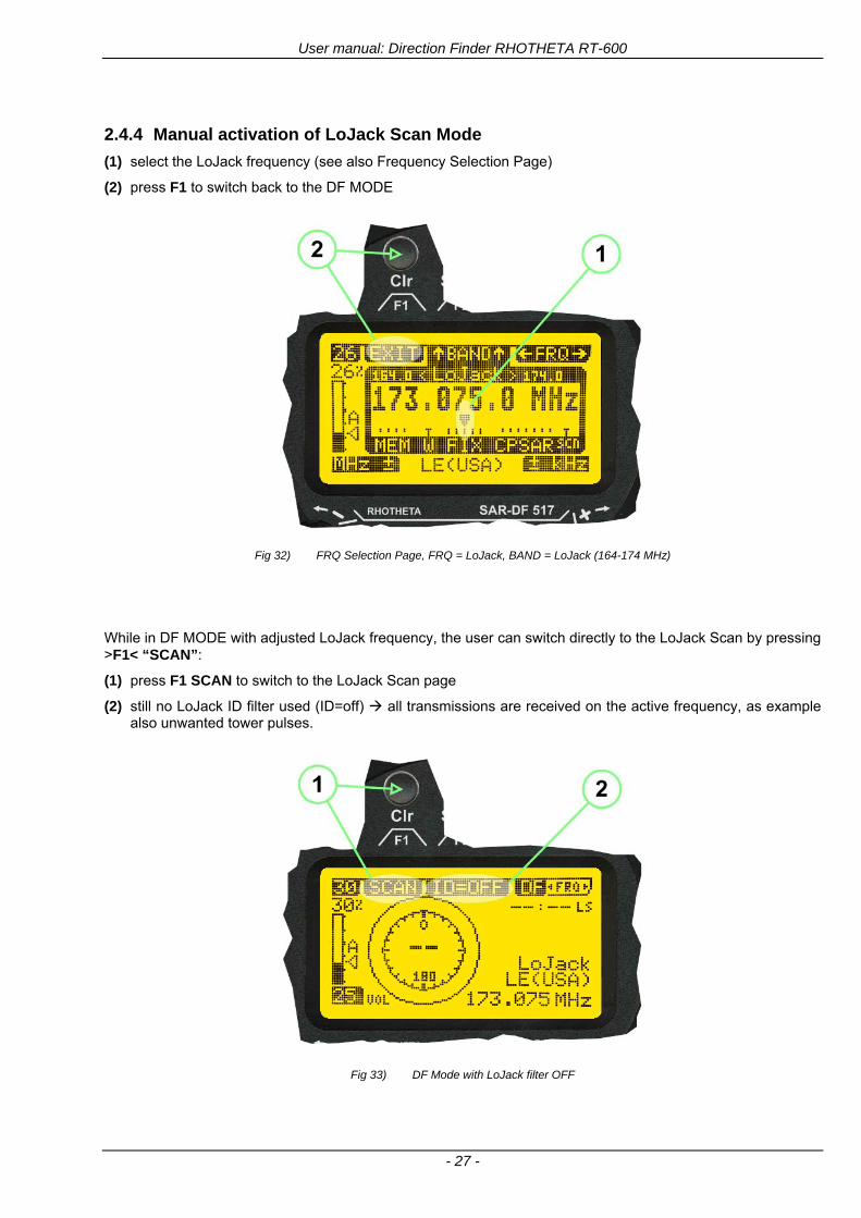
User manual Direction Finder RHOTHETA RT-600
- 27 -
244 Manual activation of LoJack Scan Mode
(1) select the LoJack frequency (see also Frequency Selection Page)
(2) press F1 to switch back to the DF MODE
Fig 32) FRQ Selection Page FRQ = LoJack BAND = LoJack (164-174 MHz)
While in DF MODE with adjusted LoJack frequency the user can switch directly to the LoJack Scan by pressing gtF1lt ldquoSCANrdquo
(1) press F1 SCAN to switch to the LoJack Scan page
(2) still no LoJack ID filter used (ID=off) all transmissions are received on the active frequency as example also unwanted tower pulses
Fig 33) DF Mode with LoJack filter OFF
User manual Direction Finder RHOTHETA RT-600
- 28 -
245 Receiving and accepting a new VLU Code
While in LoJack Scan Mode waiting for a VLU Code if a new VLU Code is displayed the user can accept it and switch directly to DF Mode by pressing F2
(1) a new LoJack VLU Code (0001A) has been received
(2) press F2 to accept the new VLU Code (0001A) and switch to DF MODE page with the LoJack filter activated to track only 0001A
Fig 34) LoJack Scan Mode with new VLU Code received
246 Entering a new VLU Code manually
While in LoJack Scan Mode the user can enter a LoJack VLU code also manually
(1 2 3) use the SELECTplusmn and plusmnVALUE knobs to enter a new LoJack VLU Code active ID (0001A)
(4) Press F1 to accept the new VLU Code and switch to DF Mode with the LoJack filter ON to track only 0001A
Fig 35) LoJack Scan Mode with new VLU Code entered manually
User manual Direction Finder RHOTHETA RT-600
- 29 -
247 Tracking one VLU Code while monitoring new VLU Codes
While on DF Mode and tracking a VLU Code (0001A) the user can turn the LoJack switch OFF with F2 also the user can start scanning all VLUs again with F1
0001A is displayed as the active VLU Code filter function is ON only 0001A is tracked
Monitoring of other VLU Codes is active in the background
(1) Press F1 to switch to the LoJack Scan Mode to scan for new VLU Codes
(2) Press F2 to switch LoJack filter OFF
Fig 36) DF Mode with active VLU Code and LoJack filter ON
248 Tracking one VLU Code and receiving a new VLU Code
While on DF MODE page and tracking VLU Code (0001A) in the background a new VLU Code is received and decoded (G2HC7)
(1) The new VLU Code is announced (NEW G2HC7)
(2) Press F1 to switch to LoJack Scan Mode to see the arrival time of G2HC7 and the possibility to change bearing to this new G2HC7
Fig 37) DF Mode with active VLU Code and announcement of new VLU Code
User manual Direction Finder RHOTHETA RT-600
- 30 -
249 Switching to a new VLU Code
While on the LoJack Scan Page tracking one VLU Code (0001A) and notified of a new VLU Code (G2HC7)
(1) press F1 to continue tracking 0001A
(2) press F2 to start tracking G2HC7
(3) Time elapsed since G2HC7 was last received
(4) Time elapsed since 0001A was last received
If F1 is pressed for 2 sec the indicated VLU Code (G2HC7) and ID (0001A) are deleted
Fig 38) LoJack Scan Page with one active VLU Code and one new VLU Code
2410 ldquoBlockingrdquo function of one LoJack VLU Code
The LoJack scan page can also be used to ldquoblockrdquo one unwanted LoJack VLU ID signal by separating the adjusted active ID from any other received LoJack VLU signal This is done by muting the audio (see example below) when a LoJack signal with VLU code ldquo0001Ardquo is received gtgt Any new VLU Code (active LoJack signal) - except for 0001A ndash will be displayed on the top row and generate the audible beep tone
Fig 39) LoJack Scan Page with one active VLU Code and audio OFF
Tip ldquoBlockingrdquo is an important tool for practical missions As example a stolen vehicle with VLU ID ldquo0001Ardquo was tracked in the DF bearing mode The mission
is completed but the VLU is normally still transmitting With the settings above only new VLU signals except the now unwanted ldquo0001Ardquo are audible and displayed in the upper (scan LoJack hellip for new VLU) box
User manual Direction Finder RHOTHETA RT-600
- 31 -
2411 Tracking in the 216 to 220 MHz band
The RT-600 features scanning and bearing functionality in the 216000 MHz to 220000 MHz band The 216000 MHz ndash 220000 MHz band contains frequencies and signals used by special services and tracked by law enforcement special ops and similar organizations These are some of the frequencies and services in this band
CFR 90259 tx 216000 MHz to 220000 MHz
Low Power Radio Service (LPRS) tx 216000 MHz to 217000 MHz
Medical beacons Project Lifesaver tx wristankle tx 213000 MHz to 216000 MHz
ETS tx stolen cashasset recovery tx ldquobaitrdquordquotagrdquo tx 216000 MHz to 220000 MHz tx = transmitter(s) However any future or current user of the Rhotheta RT-600 must be aware that tracking signals on the frequencies listed above may be challenging and even frustrating due mostly to negative factors in some of the transmitters
bull Very low RF power output
bull Inefficient antennas
bull Battery-powered devices with a ldquolow batteryrdquo condition
bull Devices worn or located in conditions of poor RF propagation
bull Devices with channel spacing different than the one specified for the RT-600
These factors can make it very difficult for the DF to receive the signal andor display an accurate bearing Disclaimer For the reasons explained above and even though the RT-600 features top performance in its class RHOTHETA does not offer - and is not to be held responsible for - any guaranteed minimum range or distance to a transmitter in this band
25 Setup Edit Page System settings are displayed in the setup page The functions described in this section should be used by trained personal only
Fig 40) Accessing the Setup Page
The setup page can be accessed by holding down the gtCLRlt (1) and gtREPlt (2) buttons simultaneously and in the same time performing a left-hand turn on the gtPagelt rotary switch (3)
User manual Direction Finder RHOTHETA RT-600
- 32 -
Fig 41) Setup Page
(1) gtStorelt push-button must be pressed in parallel if a value of a setting shall be modified If a value can
be modified the background stops to blink
(2) gtSelectlt rotary switch used to scroll through the menu options The value of the actually activated menu option is high-lighted with dark background and blinking
(3) gtValuelt rotary switch used to change values in menu options (gtStorelt (1) has to be pressed in parallel if a value shall be modified)
(4) gtSN-Ratiolt menu option representing the necessary Signal-To-Noise-Ratio (Difference between signal and noise level) used as criterion for the automatic squelch function Please refer to the chapter ldquoSquelch Operationrdquo for details Default value is 60 dB
(5) gtMounting Positionlt menu option to select Top- or Bottom-Mounting of the DF antenna In case of rooftop installation (eg on land vehicles) ldquoToprdquo shall be selected In case of bottom-down (upside-down) installation (eg on a helicopter) ldquoBotrdquo shall be selected If this option is not selected correctly all bearing values will be mirror-inverted
(6) gtBearing Offsetlt menu option to include a constant offset correction to the bearing indication Bearing values in degrees will be changed according to the offset value
(7) gtMaximum External Dimming Voltage for Legendslt menu option which sets the upper limit of the dimming input voltage for the legends-panel Range=[15 hellip 28]V
(8) gtMinimum External Dimming Voltage for Legendslt menu option which sets the lower limit of the dimming input voltage for the legends-panel Range=[15 hellip 28]V
(9) gtPagelt rotary switch to be turned right-hand to go back to the Direction Finder page A left-hand turn on this rotary switch will show up an additional service page with debug information used for system checks
(10) gtExtended Seriallt It is possible to enable or disable the extended serial data protocol Only of interest if serial data is used by any connected control units like moving maps or computers For detailed information see (Serial interface data protocol (short description)gt at page 46) If there are compatibility problems with already existing older remote control software it is recommended to switch OFF the extended serial data protocol
User manual Direction Finder RHOTHETA RT-600
- 33 -
3 Error messages If an internal error of the device is recognized a corresponding flashing error message will be shown in the DF pages
Fig 42) Error Messages
(1) Error message including error code (in brackets)
(2) Short description of the indicated error
In case of coincidence of various errors the error with the highest priority will be displayed
Error message Error location Reason
Error (12) VOLTDU
Main voltage supply Main Voltage input too low ( 100 V)
Error (11) NO AU
Connection antenna display or Antenna Unit
No serial data (RS485) from Antenna Unit No or damaged connection between antenna and display or damaged antenna unit
Error (10) BAD AU
Connection antenna display
Incompatibility or bad data connection between display and antenna
Error (9) BAD RU
Remote Unit Incompatibility or bad data connection between display and external serial Remote Unit or PC
Error (8) VOLTAU
Antenna Unit Voltage supply at Antenna Unit too low ( 90 V) Main voltage supply too low or considerable drop of voltage between display and antenna
Error (7) BAD DCU
Connection Display Antenna
Incompatibility or bad data connection between antenna and display
Error (6) NO DCU
Connection Display Antenna
No serial data from Display Control Unit to Antenna Unit
Error (5) PLL ERR
antenna Error in synthesizer-oscillator of receiver in Antenna Unit
Error (4) FRQ+OFS
received transmitter Received frequency too high (more than 6 KHz error of transmitter)
Error (3) FRQ-OFS
received transmitter received frequency too low (more than 6 KHZ error of transmitter)
Error (2) DECODE
radio distance transmitter DF
Data Bits of decoded signal (COSPAS-SARSAT or LoJack) defective
Error (1) DATARNG
Incompatibility of data DCU AU
Protocol data bytes out of valid range
Error (0) NO REC
Antenna Unit receiver
Receiver board defective
User manual Direction Finder RHOTHETA RT-600
- 34 -
4 Installation
41 Antenna unit A convenient position of the monopole bearing antenna is crucial for good bearing results The antenna needs an effective ground connection to the body of the aircraft or to the roof of the vehicle If there is no metallic mounting surface available a metallic sheet or similar (net) with connection to ground has to be applied first between vehicle-body and antenna In this hatched area the antenna touches the body ofthe vehicleaircraft In order to obtain a good groundconnection the surface of the body should be bared(Measuring unit [mm])
8 x holes for mounting the antenna unit to the
vehicle aircraft
Fig 43) Antenna Mounting Drawing
User manual Direction Finder RHOTHETA RT-600
- 35 -
411 Influence of antenna location and environment on the bearing accuracy
Recommendations concerning the practical antenna unit location on helicopters and airplanes
The bearing accuracy of the direction finder antenna unit is severely influenced (comparable to an airspeed sensor) by the environment For comparison a perfect high quality speed sensor will not indicate the true airspeed if this sensor is interfered by strong turbulences The direction finder antenna unit acts as a sensor for electromagnetic waves In the near field of this antenna unit any conductive (eg metallic) obstacle will influence the incoming wave field and create reflections which decrease the bearing accuracy These are general physical limitations concerning all types of direction finder systems To achieve the best bearing results it should be considered that the antenna unit is installed as far away as possible from any other vertically polarized conductive structure If possible there should be no reflectors within an area of 2-3 feet around the antenna unit In this worst case example the direction finder will not work properly
Fig 44) Antenna Installed in a Bad Location
In this example the antenna unit is located too close to the cable cutter of the helicopter This cutter will produce strong reflections especially as the length is equal to Lambda4 within the VHF airband
User manual Direction Finder RHOTHETA RT-600
- 36 -
Examples of properly installed direction finder antenna units
Fig 45) Antenna Installed in Good Locations
User manual Direction Finder RHOTHETA RT-600
- 37 -
42 Display and Control Unit
The display control unit may be mounted into a front panel by the means of this mounting drawing
Fig 46) DCU Mounting Drawing
(all dimensions in [mm]) To install or uninstall the display control unit perform the following steps (1) Remove the cover caps of the four rotary switches
(2) Loose the screws visible below the position of the cover caps
(3) Remove the plastic button from the axis of the four rotary switches
(4) Mount dismount the display control unit
(5) Re-install the plastic buttons on the axis of the four rotary switches
(6) Fix the screws so that the plastic buttons are fixed on the axis
(7) Re-install the cover caps on the four rotary switches
User manual Direction Finder RHOTHETA RT-600
- 38 -
43 System Interconnect Wiring Diagram (Also refer to chapter ldquoTechnical Datardquo for details)
Fig 47) System Interconnect Wiring Diagram
6-pol Amphenol plug femalePTG06SE10-6S(SQ)
max length of cable 20 m 9-pol Sub-D plug (femalemale)
User manual Direction Finder RHOTHETA RT-600
- 39 -
5 Technical Data
51 Electric features
Method of bearing Doppler-principle (3 kHz rotational frequency right left rotation)
Bearing accuracy1 plusmn 5deg RMS
Internal resolution 1deg
Bearing Sensitivity VHF AirEmergency le 25 μVm (typical)
VHF Marine le 25 μVm (typical)
UHF Emergency and ETS le 4 μVm (typical)
COSPAS-SARSAT le 4 μVm (typical)
LoJack Decoding (50 Message Error Rate) and bearing le 5 μVm (typical)
Frequency stability plusmn 20 ppm (Δff = plusmn210-6)
Reception frequencies
SAR version (Standard)
Frequency Options
VHF Emergency Band 118000 to 124000 MHz (833 kHz steps AM)
VHF Marine Band 154000 to 163000 MHz ( 500 kHz steps FM) (channel 16 selectable via channel no)
UHF Emergency Band 240000 to 246000 MHz (2500 kHz steps AM)
UHF FM Band 406100 to 410000 MHz ( 500 kHz steps FM)
COSPAS-SARSAT 400000 to 406092 MHz Including 406022 to 406076 MHz (Channel A S)
F1 VHF Air Band 118000 to 136992 MHz
F2 extended VHF Marine Band 137000 to 224995 MHz
F3 extended UHF Air Band 225000 to 399975 MHz
F4 additional UHF FM Band 406100 to 470000 MHz
Reception frequencies
LAW Enforcement version
Frequency Options
VHF Emergency Band 118000 to 124000 MHz (833 kHz steps AM)
VHF Marine Band 154000 to 163000 MHz (500 kHz steps FM) (channel 16 selectable via channel no)
LoJack 164000 to 174000 MHz (125 kHz steps FM)
ETS 216000 to 220000 MHz (10125 kHz AM)
COSPAS-SARSAT 400000 to 406092 MHz Including 406022 to 406076 MHz (Channel A S)
F1VHF Air Band 118000 to 136992 MHz
F2 extended VHF Marine Band 137000 to 163000 MHz
COSPAS-SARSAT fast scan mode
Full automatic detection of any active COSPAS-SARSAT channel A to S within 400 ms
COSPAS-SARSAT decoding
Reception and decoding of COSPAS-SARSAT data signal (112 or 144 bit) specified according to COSPAS-SARSAT
LoJack decoding Selectable LoJack ID display and selective active filtering
Special scanning modes
complete maritime ship band scanning within 3 s (channel 01 hellip 88 also frequencies between 2 channels are included)
1With undisturbed wave field and sufficient field strength Measuring by changing the angle of incidence with the antenna rotating on a revolving table in order to eliminate environmental influences on the results No modulation
User manual Direction Finder RHOTHETA RT-600
- 40 -
Bearable modulation A3E F3E A3X (ELT-modulation) F1D G2D COSPAS-SARSAT Bearing largely independent of modulation
Polarization Vertical
Polarization error 5deg at 60deg field vector rotation
Garbling cone Ca 30deg to the vertical
Time of response2 50 ms (with sufficient reception field strength)
LC-graphic display 128 x 64 pixels supertwist transflective extended range of temperature dark-blue display on yellow-green background background light Freely adjustable (exponential) dimming of brightness
NVG cockpit design Fully compatible NVIS Green B display Control Unit optional
Operating voltage 275 V nominal 12 V to 35 V DC
Current consumption LCD-background light Off max 500 mA (12 V DC) max 250 mA (24 V DC)
LCD-background light 100 max 750 mA (12 V DC) max 350 mA (24 V DC)
LCD-background light 100 max 900 mA (12 V DC) with NVG Option max 400 mA (24 V DC)
Audio out For external speaker approx 2 W (4 Ω)
Serial data interface Serial interface RS-232 (9600 baud 8 data bits 1 stop bit no parity)
2Very weak signals can considerably increase the time of response
User manual Direction Finder RHOTHETA RT-600
- 41 -
52 Interface External connections (optional at Sub-D 9-pol Male connector)
Dimming
Pin 8
external voltage input for variable dimming of legends
(optional)
Analog input signal for variable control of the legends illumination Input voltage range is freely adjustable in the range of 15 hellip 28 V in the setup menu Refer to chapter ldquoSetup Pagerdquo Default setting 8 hellip28 V (8 V = Off 28 V = max dimming for legends)
Input Impedance gt 50 k
Pin 6 night status line for LCD
dimming (optional)
Low-active (as example switch to ground) At input voltage lt 25 VDC the LCD dimming operates in nightNVG mode Maximum brightness ca 4 of daydefault mode brightness
Input Impedance gt 50 k
Pin 4 NVG status line for LCD
dimming (optional)
Low-active (as example switch to ground) At input voltage lt 25 VDC the LCD dimming operates in nightNVG mode Maximum brightness ca 4 of daydefault mode brightness
Input Impedance gt 50 k
AudioLF
Pin 7 Audio output signal
AC coupled voltage source with very low inner resistance Maximum output voltage ca 8 VPP = 283V RMS at maximum Volume Maximum output power ca 2 W with 4 speaker
If a headphone is connected ([32hellip600] 100mW) we recommend using a resistor (18 025 W) between audio output and headphone to prevent damage of the headphone
Serial interface RS232 (9600 baud 8 data bits 1 stop bit no parity)
Pin 3 TXD Serial output (ca plusmn10 V)
Pin 2 RXD Serial input (ca plusmn10 V)
User manual Direction Finder RHOTHETA RT-600
- 42 -
53 Mechanical features
Temperature range
Display Control Unit permissible operating temperature3 -20 degC +60 degC permissible storage temperature -30 degC +80 degC
Antenna Unit permissible operating temperature3 -40 degC +60 degC permissible storage temperature -55 degC +80 degC
Protective system Antenna Unit IP 67
Weights Display Control Unit 250 g Antenna Unit 2000 g
Dimensions Display Control Unit 82 mm x 82 mm x 43 mm (width x height x depth) Antenna Unit 270 mm x 185 mm
Fig 48) DCU Mechanical Drawing (all dimensions in [mm])
3 For temperatures lower than ndash10deg C a warm-up period of 15 min should be allowed
User manual Direction Finder RHOTHETA RT-600
- 43 -
Fig 49) AU Mechanical Drawing (all dimensions in [mm])
User manual Direction Finder RHOTHETA RT-600
- 44 -
6 Appendix
61 Frequency Ranges
User manual Direction Finder RHOTHETA RT-600
- 45 -
62 Frequencies of channels on maritime band (only for standard [A] version) Frequency-range of the RT-600 in the maritime band 156000 MHz 162025 MHz
Channel No frequency (ship - station) Frequency (coast - station)
1 156050 MHz 160650 MHz 2 156100 MHz 160700 MHz 3 156150 MHz 160750 MHz 4 156200 MHz 160800 MHz 5 156250 MHz 160850 MHz 6 156300 MHz 160900 MHz 7 156350 MHz 160950 MHz 8 156400 MHz 9 156450 MHz
10 156500 MHz 11 156550 MHz 12 156600 MHz 13 156650 MHz 14 156700 MHz 15 156750 MHz 16 156800 MHz 17 156850 MHz 18 156900 MHz 161500 MHz 19 156950 MHz 161550 MHz 20 157000 MHz 161600 MHz 21 157050 MHz 161650 MHz 22 157100 MHz 161700 MHz 23 157150 MHz 161750 MHz 24 157200 MHz 161800 MHz 25 157250 MHz 161850 MHz 26 157300 MHz 161900 MHz 27 157350 MHz 161950 MHz 28 157400 MHz 162000 MHz 60 156025 MHz 160625 MHz 61 156075 MHz 160675 MHz 62 156125 MHz 160725 MHz 63 156175 MHz 160775 MHz 64 156225 MHz 160825 MHz 65 156275 MHz 160875 MHz 66 156325 MHz 160925 MHz 67 156375 MHz 68 156425 MHz 69 156475 MHz 70 156525 MHz 71 156575 MHz 72 156625 MHz 73 156675 MHz 74 156725 MHz 75 156775 MHz 76 156825 MHz 77 156875 MHz 78 156925 MHz 161525 MHz 79 156975 MHz 161575 MHz 80 157025 MHz 161625 MHz 81 157075 MHz 161675 MHz 82 157125 MHz 161725 MHz 83 157175 MHz 161775 MHz 84 157225 MHz 161825 MHz 85 157275 MHz 161875 MHz 86 157325 MHz 161925 MHz 87 157375 MHz 161975 MHz 88 157425 MHz 162025 MHz
User manual Direction Finder RHOTHETA RT-600
- 46 -
63 Serial interface data protocol (short description)
631 General
Interface parameters RS232 9600 Baud 8 databits 1 stopbit no parity LSB sent first Timing of serial data For accurate use of the serial data (even for the optional serial input commands) the correct timing is mandatory The DCU (Display Control Unit) sends out via the RS-232 Pins (see 43 System Interconnect Wiring Diagram page 38) cyclic and autonomous every approx 250300 ms a binary data stream which contains all relevant DF-bearing information The output data contains one or two blocks of binary data (see next picture with accordingly description) The optional serial input is only used if changes (as example frequency change) are done by additional remote control units
Fig 50) Timing of serial data
Serial standard output
This output data is always available and contains all relevant DF-bearing data For detailed content see page 47
Optional extended serial output
This data contains some additional information like as example CospasSarsat or LoJack decoding and ID data For detailed content see page 50 The data is only available with DCU Software [Rev ge 320] and if this optional data block is configured as ON = enabled (see Setup Edit Page point (10) )
Even to avoid compatibility problems with already existing older remote control software it is possible to disable switch off this additional data block (see Setup Edit Page point (10) )
Optional serial input
Only used for optional commands to control DCU parameters If as example the direction finder frequency is changed remotely there is send to the DCU one time this data block with the new frequency For detailed content see page 52
User manual Direction Finder RHOTHETA RT-600
- 47 -
632 Serial standard output (protocol description)
Specification serial standard output
The binary data stream with a length of 39 bytes starts with a header byte (value = hex 0xA0 as ID for DF Mode) The next bytes contain different values for status bearing information and also service The last byte is used for data stream checksum control Remark This is a binary data protocol So every byte value from 0dec hellip 255dec (0x00 hellip 0xFF) is possible Because of this it is not allowed to realize a start byte detection by the content (0xA0) The idle line detection is recommended for detection the end of message Register of databytes (for details see next page)
byte no
[0] Header = 0xA0 Id for DF Mode
[1] Number = 39 = bytes in the complete message (including header and checksumbyte)
[2] Status (1) HSB [x|x|x|x|x|x|x|x] LSB | | | | | | | --gt (0) Receiving | | | | | | ----gt (1) Squelch controlled by AU (X) | | | | | ------gt (2) Permission RL Calibration | | | | --------gt (3) Line Night | | | ----------gt (4) Line NVG | | ------------gt (5) Dimming External | --------------gt (6) Autosquelch Active ----------------gt (7) 0=Standard Version 1=LE Version
[3] Status (2) HSB [x|x|x|x|x|x|x|x] LSB | ----------------gt (7) 0=Standard 1=extended serial dataprotocol = ONactive
[45] Error (Bits[120])
[6] Actual DCU Page
[7] Volume [0hellip100]
[811] Frequency [Hz]
[12] Active Band
[13] Actual Squelchlevel [0hellip60]
[14] Audio-Line amp_NF_Test Output
[15] (Not used)
[1617] Voltage_DCU ([0hellip335]=[0 hellip 335]V
[1819] Voltage_AU ([0hellip255]=[0 hellip 255]V
[20] Temperature_AU [-68hellip+127]degC
[21] Frequency Offset [-99hellip+99]
[2225] ServiceTest values (mode dependent test values for service only)
26 (Not used reserved)
[27] Level [0hellip100]
[2829] Bearing Averaged [0hellip359]deg relative
[3031] Bearing Live_Min [0hellip359]deg relative
[3233] Bearing Live_Max [0hellip359]deg relative
[34] Test Value PS-RAM Right Rotation[0hellip178] (for service only)
[35] Test Value PS-RAM Left Rotation [0hellip178] (for service only)
[3637] (Not used reserved)
[38] Checksum is the 2rsquos complement of the modulo-256 sum of all bytes without checksum-byte [0n-1]
User manual Direction Finder RHOTHETA RT-600
- 48 -
Detailed Description of important values for practical use
Status byte [2] Receiving Bit 0 of this value (LSB) indicates signal receiving Bit 0 = 0 then no signal is received and so on no bearing is available Bit 0 = 1 then bearing is possible Bit 1 if(1) then Squelch is controlled by AU (active at modes CospasSarsat Decode CospasSarsat Scanning LoJack with Filter=ID only)
Error bytes [4hellip5] 16 bit value each set bit corresponds to the error no (Refer to the chapter Error messages) Example - 0x0000 No error - 0x0800 Bit No 11 Set ( = No AU Error)
Actual DCU Page byte [6] indicates actual operating mode of DCU 0 = Standard bearing page 1 = Frequency memory page 2 = CospasSarsat decoding page 3 = LoJack decoding page (ID edit)
Frequency bytes [8hellip11] 32 bit value actual adjusted frequency [Hz] Example - 0x073DF160 1215000000 121500 MHz
Active Band Standard Version [A] 0=VHF Airband 1=VHF Marineband sea 2=VHF Marineband coast 3=UHV Airband 4=CospasSarsat LE Version [L] 0=VHF Airband 1=LoJack 2=Lifesaver 3=ETS 4=CospasSarsat
Actual Squelchlevel byte [13] Range [0hellip60] without signal the actual squelchlevel should always be adjusted a little bit over the noise level (Refer to the chapter Squelch operation)
Level byte [27] Range [099] actual receiving level (without signal this value is equal to the noise level) If a signal is received then this value corresponds to the signal strength of this signal
Relative Bearing averaged byte [2829] 16 bit value Range [0hellip359 0xFFFF] if the value = 0xFFFF then no valid bearing is available otherwise this value contains the actual averaged bearing information in Deg [0deg359deg] Example - 0X0114 276deg bearing (= left side oriented to heading)
Bearing Live MinMax byte[3031] amp [3233] - 16 bit values Range [0hellip359 0xFFFF] Only for signal quality or additional information ndash NOT recommended for bearing indication The relative live bearing field contains the maxmin bearing in degrees without averaging The relative live bearing reacts faster than the normal relative bearing but it has not the precision of the averaged bearing The MinMax Bearing Values are calculated within a time period of approx 250 ms If they are very close together (for example ldquo124rdquo and ldquo128rdquo degrees) then the signal quality is quite good A wide span of the minmax values (for example ldquo97rdquo and ldquo162rdquo) shows very noisy but nevertheless bearable signal quality
User manual Direction Finder RHOTHETA RT-600
- 49 -
633 DCU Info output (protocol description)
Specification DCU Info output
Remark This protocol is only available while the SetupEdit page is activated at the DCU
byte no
[0] Header = 0xAF Id for DCU Info Mode
[1] Number = 39 = bytes in the complete message (including header and checksumbyte)
[2]
(see standard output) [3]
[45]
[621] Info String of 15 byteschars the string contains Information about Unit Variant Software Version and Serial No
Example Byte [318] =
|--AU ID---||Var-||---Software Version---| |-------------- Serial No---------------| [0x44][0x55][0x41][0x33][0x2E][0x33][0x30][0x3A][0x20][0x20][0x30][0x31][0x32][0x33][0x34][0x00] rsquoDrsquo rsquoUrsquo rsquoArsquo rsquo3rsquo rsquorsquo rsquo3rsquo rsquo0rsquo rsquorsquo rsquo rsquo rsquo rsquo rsquo0rsquo rsquo1rsquo rsquo2rsquo rsquo3rsquo rsquo4rsquo rsquoENDrsquo | | | | __________________ | | ________________________ | n n n | | n n n n n | (Software Version) | | (Serial No) | gt rsquoArsquo = Standard Variant gt rsquoLrsquo = Law Enforcement Variant
User manual Direction Finder RHOTHETA RT-600
- 50 -
634 Optional extended serial output (protocol description)
The data content depends on the actual mode of the direction finder To get special data the direction finder has first to be switched to the equivalent mode
COSPAS-SARSAT Decoding data
This data is only available and valid if Display Control Unit with actual software Rev ge 320 (see Power-On procedure page 10) Configuration of Extended serial = ON (see Setup Edit Page point (10) ) Direction Finder COSPAS-SARSAT decoding mode is activated by selecting the corresponding page
(see COSPAS-SARSAT Decode Window page 20 and page 21) and so on Header (byte 0 of data) = 0x91
A valid COSPAS-SARSAT decoding data protocol is always marked by the first data byte (header = 0x91) Always after receiving and decoding of a valid COSPAS-SARSAT pulse the complete data protocol with 33 bytes is send out one time
Byte No
[0] Header = 0x91 (Identification for CPSarsat decoding mode)
[1] Number of bytes - 7 if no decoded pulse is available - 33 if new pulse was received and is available
[2] Error
[3] Bit[0] - 0 =gt No new 406 MSG (decoded data) available - 1 =gt New valid 406 MSG available (Sync amp Frame Ok) Check Error Status for Bit-Errors
Bit[61] AutoSquelch Level valid range [060] ( decimal)
Bit[7] = 1 Squelch controlled by AU
[4] Signallevel of received signal valid range [099] ( decimal)
[5] Voltage of Antenna Unit Power Supply input valid range [80255] (decimal = 80 255 V DC)
[6] Temperature inside Antenna Unit valid range [-50+100] (degC signed byte value)
The following databytes are only available if a correct CPSarsat puls gets received and decoded with correct checksum
[724] 18 x Databytes complete orginal CPSarsat 406 decoded message (144 bit)
Databyte Nr [ Byte 7 ] [ Byte 8 ] [Byte9 Byte24] 406 MSG Bit Nr [1 2 3 4 5 6 7 8] [9 10 11 12 13 14 15 16] [17 144]
[25] SN-Flag valid values 0x53=rsquoSrsquo 0x4E=rsquoNrsquo 0x2D=rsquo-rsquo if no GPS data available
GPS-Position Latitude
[26] Deg valid values [090] (decimal Deg) 0xFF if no GPS data available
[27] Min valid values [059] (decimal Deg) 0xFF if no GPS data available
[28] Sec valid values [059] (decimal Deg) 0xFF if no GPS data available
[29] WE-Flag valid values 0x57=rsquoWrsquo 0x45=rsquoErsquo 0x2D=rsquo-rsquo if no GPS data available
GPS-Position Longitude
[30] Deg valid values [0180] (decimal Deg) 0xFF if no GPS data available
[31] Min valid values [059] (decimal Deg) 0xFF if no GPS data available
[32] Sec valid values [059] (decimal Deg) 0xFF if no GPS data available
User manual Direction Finder RHOTHETA RT-600
- 51 -
LoJack ID data
This data is only available and valid if Display Control Unit with actual software Rev ge 320 (see Power-On procedure page 10) Direction Finder of variant [L] Law Enforcement Configuration of Extended serial = ON (see Setup Edit Page point (10) ) Direction Finder is working with active LoJack gtID Filterlt Header (byte 0 of data) = 0x93 or 0x94
Valid LoJack ID decoding data is always marked by the first data byte (header = 0x93 or 0x94)
Byte No
[0] Header = 0x93 LoJack ID editing sub-page is selected Filter = VLU all valid and received LoJack pulses are indicated = 0x94 Lojack Decode amp DF Mode with active Filter = ID
[1] Number of bytes in the complete data stream - decimal 26 = default value
[2] Nonrelevant
[3] Bit[0] Receiving OnOff - 0 =gt No Receiving no bearing - 1 =gt new LoJack pulse received
[412] Nonrelevant
[1317] Lojack ID
Replay Code 5 x ASCII Chars ldquoNo BIOZrdquo set
Example ASCII = ldquo000R1rdquo
18 Receiver Level Out Max [099]
19
LoJack Decoder Status [07] - 0 Off - 1 Wait for Preamble - 2 Preamble Ok - 3 FlagPattern Ok - 4 Data BitError gt 1 - 5 Data Ok (No VLU) - 6 VLU Ok - 7 ID Ok (Filter=IDONLY)
[2025] Nonrelevant
Remark Only if byte no [3] bit [0] gets ldquo1rdquo (Receiving On) then an active LoJack pulse is received and so on the corresponding LoJack ID valid otherwise the LoJack ID only shows the actual adjusted LoJack Filter ID of the direction finder
User manual Direction Finder RHOTHETA RT-600
- 52 -
635 Optional serial input (protocol description)
Specification serial input (optional)
The serial input is normally used for service and maintenance only Nevertheless it is possible via this interface to remote control the actual frequency and the squelchlevel of the DF system If a valid data stream is send to the DF then the actual frequency selection at the DCU is switched to Block2 AUX0 At this memory channel the new frequency is stored and used automatically (Refer to the chapter Frequency Selection Page) If the frequency is changed (by one valid data stream) no more serial input is necessary The actual frequency can be changed again at any time by manual operation at the DCU The timing of serial input (if used) is strictly fixed The optional serial input has to take place directly after a complete serial output (max 50 ms delay time) If a new changed frequency is commanded to the DCU via this serial input interface it can take up to 1 sec of time until this new frequency is ready for operationbearing It is strictly not recommended to use the frequency remote control for any scan mode The frequency control has to be used for static frequency change only Register of databytes
byte no
[0] Header 0xC0
[1] Number of bytes in the complete message (including header and checksumbyte)
[23] (not used for normal operation any byte values allowed)
[4] Volume [0100]
[58] Frequency [Hz] (frequency is rounded to the according grid automatically)
Valid Range for Standard Version Valid Range for LE Version
118000000 hellip 123000000 [Hz] 8333 kHz 118000000 hellip 123000000 [Hz] 8333 kHz
156050000 hellip 162025000 [Hz] 5000 kHz 164000000 hellip 174000000 [Hz] 8333 kHz
201000000 hellip 215995000 [Hz] 5000 kHz
240000000 hellip 246000000 [Hz] 8333 kHz 216000000 hellip 218995000 [Hz] 12500 kHz219000000 hellip 220000000 [Hz] 10000 kHz
400000000 hellip 410000000 [Hz] 8333 kHz 400000000 hellip 410000000 [Hz] 8333 kHz
[9] Squelchlevel Manual = [0hellip60] Autosql= [ -1] Warning use only for pulsed signals (as example CpSarsat LoJack)
[10] (not used for normal operation any byte values allowed)
[11] Internal Dimming [0100]
[12] Checksum is the 2rsquos complement of the modulo-256 sum of all bytes without checksum-byte [0n-1]
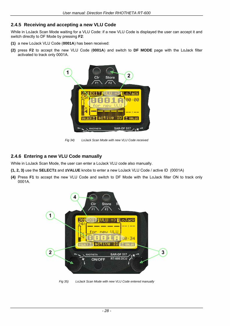
User manual Direction Finder RHOTHETA RT-600
- 28 -
245 Receiving and accepting a new VLU Code
While in LoJack Scan Mode waiting for a VLU Code if a new VLU Code is displayed the user can accept it and switch directly to DF Mode by pressing F2
(1) a new LoJack VLU Code (0001A) has been received
(2) press F2 to accept the new VLU Code (0001A) and switch to DF MODE page with the LoJack filter activated to track only 0001A
Fig 34) LoJack Scan Mode with new VLU Code received
246 Entering a new VLU Code manually
While in LoJack Scan Mode the user can enter a LoJack VLU code also manually
(1 2 3) use the SELECTplusmn and plusmnVALUE knobs to enter a new LoJack VLU Code active ID (0001A)
(4) Press F1 to accept the new VLU Code and switch to DF Mode with the LoJack filter ON to track only 0001A
Fig 35) LoJack Scan Mode with new VLU Code entered manually
User manual Direction Finder RHOTHETA RT-600
- 29 -
247 Tracking one VLU Code while monitoring new VLU Codes
While on DF Mode and tracking a VLU Code (0001A) the user can turn the LoJack switch OFF with F2 also the user can start scanning all VLUs again with F1
0001A is displayed as the active VLU Code filter function is ON only 0001A is tracked
Monitoring of other VLU Codes is active in the background
(1) Press F1 to switch to the LoJack Scan Mode to scan for new VLU Codes
(2) Press F2 to switch LoJack filter OFF
Fig 36) DF Mode with active VLU Code and LoJack filter ON
248 Tracking one VLU Code and receiving a new VLU Code
While on DF MODE page and tracking VLU Code (0001A) in the background a new VLU Code is received and decoded (G2HC7)
(1) The new VLU Code is announced (NEW G2HC7)
(2) Press F1 to switch to LoJack Scan Mode to see the arrival time of G2HC7 and the possibility to change bearing to this new G2HC7
Fig 37) DF Mode with active VLU Code and announcement of new VLU Code
User manual Direction Finder RHOTHETA RT-600
- 30 -
249 Switching to a new VLU Code
While on the LoJack Scan Page tracking one VLU Code (0001A) and notified of a new VLU Code (G2HC7)
(1) press F1 to continue tracking 0001A
(2) press F2 to start tracking G2HC7
(3) Time elapsed since G2HC7 was last received
(4) Time elapsed since 0001A was last received
If F1 is pressed for 2 sec the indicated VLU Code (G2HC7) and ID (0001A) are deleted
Fig 38) LoJack Scan Page with one active VLU Code and one new VLU Code
2410 ldquoBlockingrdquo function of one LoJack VLU Code
The LoJack scan page can also be used to ldquoblockrdquo one unwanted LoJack VLU ID signal by separating the adjusted active ID from any other received LoJack VLU signal This is done by muting the audio (see example below) when a LoJack signal with VLU code ldquo0001Ardquo is received gtgt Any new VLU Code (active LoJack signal) - except for 0001A ndash will be displayed on the top row and generate the audible beep tone
Fig 39) LoJack Scan Page with one active VLU Code and audio OFF
Tip ldquoBlockingrdquo is an important tool for practical missions As example a stolen vehicle with VLU ID ldquo0001Ardquo was tracked in the DF bearing mode The mission
is completed but the VLU is normally still transmitting With the settings above only new VLU signals except the now unwanted ldquo0001Ardquo are audible and displayed in the upper (scan LoJack hellip for new VLU) box
User manual Direction Finder RHOTHETA RT-600
- 31 -
2411 Tracking in the 216 to 220 MHz band
The RT-600 features scanning and bearing functionality in the 216000 MHz to 220000 MHz band The 216000 MHz ndash 220000 MHz band contains frequencies and signals used by special services and tracked by law enforcement special ops and similar organizations These are some of the frequencies and services in this band
CFR 90259 tx 216000 MHz to 220000 MHz
Low Power Radio Service (LPRS) tx 216000 MHz to 217000 MHz
Medical beacons Project Lifesaver tx wristankle tx 213000 MHz to 216000 MHz
ETS tx stolen cashasset recovery tx ldquobaitrdquordquotagrdquo tx 216000 MHz to 220000 MHz tx = transmitter(s) However any future or current user of the Rhotheta RT-600 must be aware that tracking signals on the frequencies listed above may be challenging and even frustrating due mostly to negative factors in some of the transmitters
bull Very low RF power output
bull Inefficient antennas
bull Battery-powered devices with a ldquolow batteryrdquo condition
bull Devices worn or located in conditions of poor RF propagation
bull Devices with channel spacing different than the one specified for the RT-600
These factors can make it very difficult for the DF to receive the signal andor display an accurate bearing Disclaimer For the reasons explained above and even though the RT-600 features top performance in its class RHOTHETA does not offer - and is not to be held responsible for - any guaranteed minimum range or distance to a transmitter in this band
25 Setup Edit Page System settings are displayed in the setup page The functions described in this section should be used by trained personal only
Fig 40) Accessing the Setup Page
The setup page can be accessed by holding down the gtCLRlt (1) and gtREPlt (2) buttons simultaneously and in the same time performing a left-hand turn on the gtPagelt rotary switch (3)
User manual Direction Finder RHOTHETA RT-600
- 32 -
Fig 41) Setup Page
(1) gtStorelt push-button must be pressed in parallel if a value of a setting shall be modified If a value can
be modified the background stops to blink
(2) gtSelectlt rotary switch used to scroll through the menu options The value of the actually activated menu option is high-lighted with dark background and blinking
(3) gtValuelt rotary switch used to change values in menu options (gtStorelt (1) has to be pressed in parallel if a value shall be modified)
(4) gtSN-Ratiolt menu option representing the necessary Signal-To-Noise-Ratio (Difference between signal and noise level) used as criterion for the automatic squelch function Please refer to the chapter ldquoSquelch Operationrdquo for details Default value is 60 dB
(5) gtMounting Positionlt menu option to select Top- or Bottom-Mounting of the DF antenna In case of rooftop installation (eg on land vehicles) ldquoToprdquo shall be selected In case of bottom-down (upside-down) installation (eg on a helicopter) ldquoBotrdquo shall be selected If this option is not selected correctly all bearing values will be mirror-inverted
(6) gtBearing Offsetlt menu option to include a constant offset correction to the bearing indication Bearing values in degrees will be changed according to the offset value
(7) gtMaximum External Dimming Voltage for Legendslt menu option which sets the upper limit of the dimming input voltage for the legends-panel Range=[15 hellip 28]V
(8) gtMinimum External Dimming Voltage for Legendslt menu option which sets the lower limit of the dimming input voltage for the legends-panel Range=[15 hellip 28]V
(9) gtPagelt rotary switch to be turned right-hand to go back to the Direction Finder page A left-hand turn on this rotary switch will show up an additional service page with debug information used for system checks
(10) gtExtended Seriallt It is possible to enable or disable the extended serial data protocol Only of interest if serial data is used by any connected control units like moving maps or computers For detailed information see (Serial interface data protocol (short description)gt at page 46) If there are compatibility problems with already existing older remote control software it is recommended to switch OFF the extended serial data protocol
User manual Direction Finder RHOTHETA RT-600
- 33 -
3 Error messages If an internal error of the device is recognized a corresponding flashing error message will be shown in the DF pages
Fig 42) Error Messages
(1) Error message including error code (in brackets)
(2) Short description of the indicated error
In case of coincidence of various errors the error with the highest priority will be displayed
Error message Error location Reason
Error (12) VOLTDU
Main voltage supply Main Voltage input too low ( 100 V)
Error (11) NO AU
Connection antenna display or Antenna Unit
No serial data (RS485) from Antenna Unit No or damaged connection between antenna and display or damaged antenna unit
Error (10) BAD AU
Connection antenna display
Incompatibility or bad data connection between display and antenna
Error (9) BAD RU
Remote Unit Incompatibility or bad data connection between display and external serial Remote Unit or PC
Error (8) VOLTAU
Antenna Unit Voltage supply at Antenna Unit too low ( 90 V) Main voltage supply too low or considerable drop of voltage between display and antenna
Error (7) BAD DCU
Connection Display Antenna
Incompatibility or bad data connection between antenna and display
Error (6) NO DCU
Connection Display Antenna
No serial data from Display Control Unit to Antenna Unit
Error (5) PLL ERR
antenna Error in synthesizer-oscillator of receiver in Antenna Unit
Error (4) FRQ+OFS
received transmitter Received frequency too high (more than 6 KHz error of transmitter)
Error (3) FRQ-OFS
received transmitter received frequency too low (more than 6 KHZ error of transmitter)
Error (2) DECODE
radio distance transmitter DF
Data Bits of decoded signal (COSPAS-SARSAT or LoJack) defective
Error (1) DATARNG
Incompatibility of data DCU AU
Protocol data bytes out of valid range
Error (0) NO REC
Antenna Unit receiver
Receiver board defective
User manual Direction Finder RHOTHETA RT-600
- 34 -
4 Installation
41 Antenna unit A convenient position of the monopole bearing antenna is crucial for good bearing results The antenna needs an effective ground connection to the body of the aircraft or to the roof of the vehicle If there is no metallic mounting surface available a metallic sheet or similar (net) with connection to ground has to be applied first between vehicle-body and antenna In this hatched area the antenna touches the body ofthe vehicleaircraft In order to obtain a good groundconnection the surface of the body should be bared(Measuring unit [mm])
8 x holes for mounting the antenna unit to the
vehicle aircraft
Fig 43) Antenna Mounting Drawing
User manual Direction Finder RHOTHETA RT-600
- 35 -
411 Influence of antenna location and environment on the bearing accuracy
Recommendations concerning the practical antenna unit location on helicopters and airplanes
The bearing accuracy of the direction finder antenna unit is severely influenced (comparable to an airspeed sensor) by the environment For comparison a perfect high quality speed sensor will not indicate the true airspeed if this sensor is interfered by strong turbulences The direction finder antenna unit acts as a sensor for electromagnetic waves In the near field of this antenna unit any conductive (eg metallic) obstacle will influence the incoming wave field and create reflections which decrease the bearing accuracy These are general physical limitations concerning all types of direction finder systems To achieve the best bearing results it should be considered that the antenna unit is installed as far away as possible from any other vertically polarized conductive structure If possible there should be no reflectors within an area of 2-3 feet around the antenna unit In this worst case example the direction finder will not work properly
Fig 44) Antenna Installed in a Bad Location
In this example the antenna unit is located too close to the cable cutter of the helicopter This cutter will produce strong reflections especially as the length is equal to Lambda4 within the VHF airband
User manual Direction Finder RHOTHETA RT-600
- 36 -
Examples of properly installed direction finder antenna units
Fig 45) Antenna Installed in Good Locations
User manual Direction Finder RHOTHETA RT-600
- 37 -
42 Display and Control Unit
The display control unit may be mounted into a front panel by the means of this mounting drawing
Fig 46) DCU Mounting Drawing
(all dimensions in [mm]) To install or uninstall the display control unit perform the following steps (1) Remove the cover caps of the four rotary switches
(2) Loose the screws visible below the position of the cover caps
(3) Remove the plastic button from the axis of the four rotary switches
(4) Mount dismount the display control unit
(5) Re-install the plastic buttons on the axis of the four rotary switches
(6) Fix the screws so that the plastic buttons are fixed on the axis
(7) Re-install the cover caps on the four rotary switches
User manual Direction Finder RHOTHETA RT-600
- 38 -
43 System Interconnect Wiring Diagram (Also refer to chapter ldquoTechnical Datardquo for details)
Fig 47) System Interconnect Wiring Diagram
6-pol Amphenol plug femalePTG06SE10-6S(SQ)
max length of cable 20 m 9-pol Sub-D plug (femalemale)
User manual Direction Finder RHOTHETA RT-600
- 39 -
5 Technical Data
51 Electric features
Method of bearing Doppler-principle (3 kHz rotational frequency right left rotation)
Bearing accuracy1 plusmn 5deg RMS
Internal resolution 1deg
Bearing Sensitivity VHF AirEmergency le 25 μVm (typical)
VHF Marine le 25 μVm (typical)
UHF Emergency and ETS le 4 μVm (typical)
COSPAS-SARSAT le 4 μVm (typical)
LoJack Decoding (50 Message Error Rate) and bearing le 5 μVm (typical)
Frequency stability plusmn 20 ppm (Δff = plusmn210-6)
Reception frequencies
SAR version (Standard)
Frequency Options
VHF Emergency Band 118000 to 124000 MHz (833 kHz steps AM)
VHF Marine Band 154000 to 163000 MHz ( 500 kHz steps FM) (channel 16 selectable via channel no)
UHF Emergency Band 240000 to 246000 MHz (2500 kHz steps AM)
UHF FM Band 406100 to 410000 MHz ( 500 kHz steps FM)
COSPAS-SARSAT 400000 to 406092 MHz Including 406022 to 406076 MHz (Channel A S)
F1 VHF Air Band 118000 to 136992 MHz
F2 extended VHF Marine Band 137000 to 224995 MHz
F3 extended UHF Air Band 225000 to 399975 MHz
F4 additional UHF FM Band 406100 to 470000 MHz
Reception frequencies
LAW Enforcement version
Frequency Options
VHF Emergency Band 118000 to 124000 MHz (833 kHz steps AM)
VHF Marine Band 154000 to 163000 MHz (500 kHz steps FM) (channel 16 selectable via channel no)
LoJack 164000 to 174000 MHz (125 kHz steps FM)
ETS 216000 to 220000 MHz (10125 kHz AM)
COSPAS-SARSAT 400000 to 406092 MHz Including 406022 to 406076 MHz (Channel A S)
F1VHF Air Band 118000 to 136992 MHz
F2 extended VHF Marine Band 137000 to 163000 MHz
COSPAS-SARSAT fast scan mode
Full automatic detection of any active COSPAS-SARSAT channel A to S within 400 ms
COSPAS-SARSAT decoding
Reception and decoding of COSPAS-SARSAT data signal (112 or 144 bit) specified according to COSPAS-SARSAT
LoJack decoding Selectable LoJack ID display and selective active filtering
Special scanning modes
complete maritime ship band scanning within 3 s (channel 01 hellip 88 also frequencies between 2 channels are included)
1With undisturbed wave field and sufficient field strength Measuring by changing the angle of incidence with the antenna rotating on a revolving table in order to eliminate environmental influences on the results No modulation
User manual Direction Finder RHOTHETA RT-600
- 40 -
Bearable modulation A3E F3E A3X (ELT-modulation) F1D G2D COSPAS-SARSAT Bearing largely independent of modulation
Polarization Vertical
Polarization error 5deg at 60deg field vector rotation
Garbling cone Ca 30deg to the vertical
Time of response2 50 ms (with sufficient reception field strength)
LC-graphic display 128 x 64 pixels supertwist transflective extended range of temperature dark-blue display on yellow-green background background light Freely adjustable (exponential) dimming of brightness
NVG cockpit design Fully compatible NVIS Green B display Control Unit optional
Operating voltage 275 V nominal 12 V to 35 V DC
Current consumption LCD-background light Off max 500 mA (12 V DC) max 250 mA (24 V DC)
LCD-background light 100 max 750 mA (12 V DC) max 350 mA (24 V DC)
LCD-background light 100 max 900 mA (12 V DC) with NVG Option max 400 mA (24 V DC)
Audio out For external speaker approx 2 W (4 Ω)
Serial data interface Serial interface RS-232 (9600 baud 8 data bits 1 stop bit no parity)
2Very weak signals can considerably increase the time of response
User manual Direction Finder RHOTHETA RT-600
- 41 -
52 Interface External connections (optional at Sub-D 9-pol Male connector)
Dimming
Pin 8
external voltage input for variable dimming of legends
(optional)
Analog input signal for variable control of the legends illumination Input voltage range is freely adjustable in the range of 15 hellip 28 V in the setup menu Refer to chapter ldquoSetup Pagerdquo Default setting 8 hellip28 V (8 V = Off 28 V = max dimming for legends)
Input Impedance gt 50 k
Pin 6 night status line for LCD
dimming (optional)
Low-active (as example switch to ground) At input voltage lt 25 VDC the LCD dimming operates in nightNVG mode Maximum brightness ca 4 of daydefault mode brightness
Input Impedance gt 50 k
Pin 4 NVG status line for LCD
dimming (optional)
Low-active (as example switch to ground) At input voltage lt 25 VDC the LCD dimming operates in nightNVG mode Maximum brightness ca 4 of daydefault mode brightness
Input Impedance gt 50 k
AudioLF
Pin 7 Audio output signal
AC coupled voltage source with very low inner resistance Maximum output voltage ca 8 VPP = 283V RMS at maximum Volume Maximum output power ca 2 W with 4 speaker
If a headphone is connected ([32hellip600] 100mW) we recommend using a resistor (18 025 W) between audio output and headphone to prevent damage of the headphone
Serial interface RS232 (9600 baud 8 data bits 1 stop bit no parity)
Pin 3 TXD Serial output (ca plusmn10 V)
Pin 2 RXD Serial input (ca plusmn10 V)
User manual Direction Finder RHOTHETA RT-600
- 42 -
53 Mechanical features
Temperature range
Display Control Unit permissible operating temperature3 -20 degC +60 degC permissible storage temperature -30 degC +80 degC
Antenna Unit permissible operating temperature3 -40 degC +60 degC permissible storage temperature -55 degC +80 degC
Protective system Antenna Unit IP 67
Weights Display Control Unit 250 g Antenna Unit 2000 g
Dimensions Display Control Unit 82 mm x 82 mm x 43 mm (width x height x depth) Antenna Unit 270 mm x 185 mm
Fig 48) DCU Mechanical Drawing (all dimensions in [mm])
3 For temperatures lower than ndash10deg C a warm-up period of 15 min should be allowed
User manual Direction Finder RHOTHETA RT-600
- 43 -
Fig 49) AU Mechanical Drawing (all dimensions in [mm])
User manual Direction Finder RHOTHETA RT-600
- 44 -
6 Appendix
61 Frequency Ranges
User manual Direction Finder RHOTHETA RT-600
- 45 -
62 Frequencies of channels on maritime band (only for standard [A] version) Frequency-range of the RT-600 in the maritime band 156000 MHz 162025 MHz
Channel No frequency (ship - station) Frequency (coast - station)
1 156050 MHz 160650 MHz 2 156100 MHz 160700 MHz 3 156150 MHz 160750 MHz 4 156200 MHz 160800 MHz 5 156250 MHz 160850 MHz 6 156300 MHz 160900 MHz 7 156350 MHz 160950 MHz 8 156400 MHz 9 156450 MHz
10 156500 MHz 11 156550 MHz 12 156600 MHz 13 156650 MHz 14 156700 MHz 15 156750 MHz 16 156800 MHz 17 156850 MHz 18 156900 MHz 161500 MHz 19 156950 MHz 161550 MHz 20 157000 MHz 161600 MHz 21 157050 MHz 161650 MHz 22 157100 MHz 161700 MHz 23 157150 MHz 161750 MHz 24 157200 MHz 161800 MHz 25 157250 MHz 161850 MHz 26 157300 MHz 161900 MHz 27 157350 MHz 161950 MHz 28 157400 MHz 162000 MHz 60 156025 MHz 160625 MHz 61 156075 MHz 160675 MHz 62 156125 MHz 160725 MHz 63 156175 MHz 160775 MHz 64 156225 MHz 160825 MHz 65 156275 MHz 160875 MHz 66 156325 MHz 160925 MHz 67 156375 MHz 68 156425 MHz 69 156475 MHz 70 156525 MHz 71 156575 MHz 72 156625 MHz 73 156675 MHz 74 156725 MHz 75 156775 MHz 76 156825 MHz 77 156875 MHz 78 156925 MHz 161525 MHz 79 156975 MHz 161575 MHz 80 157025 MHz 161625 MHz 81 157075 MHz 161675 MHz 82 157125 MHz 161725 MHz 83 157175 MHz 161775 MHz 84 157225 MHz 161825 MHz 85 157275 MHz 161875 MHz 86 157325 MHz 161925 MHz 87 157375 MHz 161975 MHz 88 157425 MHz 162025 MHz
User manual Direction Finder RHOTHETA RT-600
- 46 -
63 Serial interface data protocol (short description)
631 General
Interface parameters RS232 9600 Baud 8 databits 1 stopbit no parity LSB sent first Timing of serial data For accurate use of the serial data (even for the optional serial input commands) the correct timing is mandatory The DCU (Display Control Unit) sends out via the RS-232 Pins (see 43 System Interconnect Wiring Diagram page 38) cyclic and autonomous every approx 250300 ms a binary data stream which contains all relevant DF-bearing information The output data contains one or two blocks of binary data (see next picture with accordingly description) The optional serial input is only used if changes (as example frequency change) are done by additional remote control units
Fig 50) Timing of serial data
Serial standard output
This output data is always available and contains all relevant DF-bearing data For detailed content see page 47
Optional extended serial output
This data contains some additional information like as example CospasSarsat or LoJack decoding and ID data For detailed content see page 50 The data is only available with DCU Software [Rev ge 320] and if this optional data block is configured as ON = enabled (see Setup Edit Page point (10) )
Even to avoid compatibility problems with already existing older remote control software it is possible to disable switch off this additional data block (see Setup Edit Page point (10) )
Optional serial input
Only used for optional commands to control DCU parameters If as example the direction finder frequency is changed remotely there is send to the DCU one time this data block with the new frequency For detailed content see page 52
User manual Direction Finder RHOTHETA RT-600
- 47 -
632 Serial standard output (protocol description)
Specification serial standard output
The binary data stream with a length of 39 bytes starts with a header byte (value = hex 0xA0 as ID for DF Mode) The next bytes contain different values for status bearing information and also service The last byte is used for data stream checksum control Remark This is a binary data protocol So every byte value from 0dec hellip 255dec (0x00 hellip 0xFF) is possible Because of this it is not allowed to realize a start byte detection by the content (0xA0) The idle line detection is recommended for detection the end of message Register of databytes (for details see next page)
byte no
[0] Header = 0xA0 Id for DF Mode
[1] Number = 39 = bytes in the complete message (including header and checksumbyte)
[2] Status (1) HSB [x|x|x|x|x|x|x|x] LSB | | | | | | | --gt (0) Receiving | | | | | | ----gt (1) Squelch controlled by AU (X) | | | | | ------gt (2) Permission RL Calibration | | | | --------gt (3) Line Night | | | ----------gt (4) Line NVG | | ------------gt (5) Dimming External | --------------gt (6) Autosquelch Active ----------------gt (7) 0=Standard Version 1=LE Version
[3] Status (2) HSB [x|x|x|x|x|x|x|x] LSB | ----------------gt (7) 0=Standard 1=extended serial dataprotocol = ONactive
[45] Error (Bits[120])
[6] Actual DCU Page
[7] Volume [0hellip100]
[811] Frequency [Hz]
[12] Active Band
[13] Actual Squelchlevel [0hellip60]
[14] Audio-Line amp_NF_Test Output
[15] (Not used)
[1617] Voltage_DCU ([0hellip335]=[0 hellip 335]V
[1819] Voltage_AU ([0hellip255]=[0 hellip 255]V
[20] Temperature_AU [-68hellip+127]degC
[21] Frequency Offset [-99hellip+99]
[2225] ServiceTest values (mode dependent test values for service only)
26 (Not used reserved)
[27] Level [0hellip100]
[2829] Bearing Averaged [0hellip359]deg relative
[3031] Bearing Live_Min [0hellip359]deg relative
[3233] Bearing Live_Max [0hellip359]deg relative
[34] Test Value PS-RAM Right Rotation[0hellip178] (for service only)
[35] Test Value PS-RAM Left Rotation [0hellip178] (for service only)
[3637] (Not used reserved)
[38] Checksum is the 2rsquos complement of the modulo-256 sum of all bytes without checksum-byte [0n-1]
User manual Direction Finder RHOTHETA RT-600
- 48 -
Detailed Description of important values for practical use
Status byte [2] Receiving Bit 0 of this value (LSB) indicates signal receiving Bit 0 = 0 then no signal is received and so on no bearing is available Bit 0 = 1 then bearing is possible Bit 1 if(1) then Squelch is controlled by AU (active at modes CospasSarsat Decode CospasSarsat Scanning LoJack with Filter=ID only)
Error bytes [4hellip5] 16 bit value each set bit corresponds to the error no (Refer to the chapter Error messages) Example - 0x0000 No error - 0x0800 Bit No 11 Set ( = No AU Error)
Actual DCU Page byte [6] indicates actual operating mode of DCU 0 = Standard bearing page 1 = Frequency memory page 2 = CospasSarsat decoding page 3 = LoJack decoding page (ID edit)
Frequency bytes [8hellip11] 32 bit value actual adjusted frequency [Hz] Example - 0x073DF160 1215000000 121500 MHz
Active Band Standard Version [A] 0=VHF Airband 1=VHF Marineband sea 2=VHF Marineband coast 3=UHV Airband 4=CospasSarsat LE Version [L] 0=VHF Airband 1=LoJack 2=Lifesaver 3=ETS 4=CospasSarsat
Actual Squelchlevel byte [13] Range [0hellip60] without signal the actual squelchlevel should always be adjusted a little bit over the noise level (Refer to the chapter Squelch operation)
Level byte [27] Range [099] actual receiving level (without signal this value is equal to the noise level) If a signal is received then this value corresponds to the signal strength of this signal
Relative Bearing averaged byte [2829] 16 bit value Range [0hellip359 0xFFFF] if the value = 0xFFFF then no valid bearing is available otherwise this value contains the actual averaged bearing information in Deg [0deg359deg] Example - 0X0114 276deg bearing (= left side oriented to heading)
Bearing Live MinMax byte[3031] amp [3233] - 16 bit values Range [0hellip359 0xFFFF] Only for signal quality or additional information ndash NOT recommended for bearing indication The relative live bearing field contains the maxmin bearing in degrees without averaging The relative live bearing reacts faster than the normal relative bearing but it has not the precision of the averaged bearing The MinMax Bearing Values are calculated within a time period of approx 250 ms If they are very close together (for example ldquo124rdquo and ldquo128rdquo degrees) then the signal quality is quite good A wide span of the minmax values (for example ldquo97rdquo and ldquo162rdquo) shows very noisy but nevertheless bearable signal quality
User manual Direction Finder RHOTHETA RT-600
- 49 -
633 DCU Info output (protocol description)
Specification DCU Info output
Remark This protocol is only available while the SetupEdit page is activated at the DCU
byte no
[0] Header = 0xAF Id for DCU Info Mode
[1] Number = 39 = bytes in the complete message (including header and checksumbyte)
[2]
(see standard output) [3]
[45]
[621] Info String of 15 byteschars the string contains Information about Unit Variant Software Version and Serial No
Example Byte [318] =
|--AU ID---||Var-||---Software Version---| |-------------- Serial No---------------| [0x44][0x55][0x41][0x33][0x2E][0x33][0x30][0x3A][0x20][0x20][0x30][0x31][0x32][0x33][0x34][0x00] rsquoDrsquo rsquoUrsquo rsquoArsquo rsquo3rsquo rsquorsquo rsquo3rsquo rsquo0rsquo rsquorsquo rsquo rsquo rsquo rsquo rsquo0rsquo rsquo1rsquo rsquo2rsquo rsquo3rsquo rsquo4rsquo rsquoENDrsquo | | | | __________________ | | ________________________ | n n n | | n n n n n | (Software Version) | | (Serial No) | gt rsquoArsquo = Standard Variant gt rsquoLrsquo = Law Enforcement Variant
User manual Direction Finder RHOTHETA RT-600
- 50 -
634 Optional extended serial output (protocol description)
The data content depends on the actual mode of the direction finder To get special data the direction finder has first to be switched to the equivalent mode
COSPAS-SARSAT Decoding data
This data is only available and valid if Display Control Unit with actual software Rev ge 320 (see Power-On procedure page 10) Configuration of Extended serial = ON (see Setup Edit Page point (10) ) Direction Finder COSPAS-SARSAT decoding mode is activated by selecting the corresponding page
(see COSPAS-SARSAT Decode Window page 20 and page 21) and so on Header (byte 0 of data) = 0x91
A valid COSPAS-SARSAT decoding data protocol is always marked by the first data byte (header = 0x91) Always after receiving and decoding of a valid COSPAS-SARSAT pulse the complete data protocol with 33 bytes is send out one time
Byte No
[0] Header = 0x91 (Identification for CPSarsat decoding mode)
[1] Number of bytes - 7 if no decoded pulse is available - 33 if new pulse was received and is available
[2] Error
[3] Bit[0] - 0 =gt No new 406 MSG (decoded data) available - 1 =gt New valid 406 MSG available (Sync amp Frame Ok) Check Error Status for Bit-Errors
Bit[61] AutoSquelch Level valid range [060] ( decimal)
Bit[7] = 1 Squelch controlled by AU
[4] Signallevel of received signal valid range [099] ( decimal)
[5] Voltage of Antenna Unit Power Supply input valid range [80255] (decimal = 80 255 V DC)
[6] Temperature inside Antenna Unit valid range [-50+100] (degC signed byte value)
The following databytes are only available if a correct CPSarsat puls gets received and decoded with correct checksum
[724] 18 x Databytes complete orginal CPSarsat 406 decoded message (144 bit)
Databyte Nr [ Byte 7 ] [ Byte 8 ] [Byte9 Byte24] 406 MSG Bit Nr [1 2 3 4 5 6 7 8] [9 10 11 12 13 14 15 16] [17 144]
[25] SN-Flag valid values 0x53=rsquoSrsquo 0x4E=rsquoNrsquo 0x2D=rsquo-rsquo if no GPS data available
GPS-Position Latitude
[26] Deg valid values [090] (decimal Deg) 0xFF if no GPS data available
[27] Min valid values [059] (decimal Deg) 0xFF if no GPS data available
[28] Sec valid values [059] (decimal Deg) 0xFF if no GPS data available
[29] WE-Flag valid values 0x57=rsquoWrsquo 0x45=rsquoErsquo 0x2D=rsquo-rsquo if no GPS data available
GPS-Position Longitude
[30] Deg valid values [0180] (decimal Deg) 0xFF if no GPS data available
[31] Min valid values [059] (decimal Deg) 0xFF if no GPS data available
[32] Sec valid values [059] (decimal Deg) 0xFF if no GPS data available
User manual Direction Finder RHOTHETA RT-600
- 51 -
LoJack ID data
This data is only available and valid if Display Control Unit with actual software Rev ge 320 (see Power-On procedure page 10) Direction Finder of variant [L] Law Enforcement Configuration of Extended serial = ON (see Setup Edit Page point (10) ) Direction Finder is working with active LoJack gtID Filterlt Header (byte 0 of data) = 0x93 or 0x94
Valid LoJack ID decoding data is always marked by the first data byte (header = 0x93 or 0x94)
Byte No
[0] Header = 0x93 LoJack ID editing sub-page is selected Filter = VLU all valid and received LoJack pulses are indicated = 0x94 Lojack Decode amp DF Mode with active Filter = ID
[1] Number of bytes in the complete data stream - decimal 26 = default value
[2] Nonrelevant
[3] Bit[0] Receiving OnOff - 0 =gt No Receiving no bearing - 1 =gt new LoJack pulse received
[412] Nonrelevant
[1317] Lojack ID
Replay Code 5 x ASCII Chars ldquoNo BIOZrdquo set
Example ASCII = ldquo000R1rdquo
18 Receiver Level Out Max [099]
19
LoJack Decoder Status [07] - 0 Off - 1 Wait for Preamble - 2 Preamble Ok - 3 FlagPattern Ok - 4 Data BitError gt 1 - 5 Data Ok (No VLU) - 6 VLU Ok - 7 ID Ok (Filter=IDONLY)
[2025] Nonrelevant
Remark Only if byte no [3] bit [0] gets ldquo1rdquo (Receiving On) then an active LoJack pulse is received and so on the corresponding LoJack ID valid otherwise the LoJack ID only shows the actual adjusted LoJack Filter ID of the direction finder
User manual Direction Finder RHOTHETA RT-600
- 52 -
635 Optional serial input (protocol description)
Specification serial input (optional)
The serial input is normally used for service and maintenance only Nevertheless it is possible via this interface to remote control the actual frequency and the squelchlevel of the DF system If a valid data stream is send to the DF then the actual frequency selection at the DCU is switched to Block2 AUX0 At this memory channel the new frequency is stored and used automatically (Refer to the chapter Frequency Selection Page) If the frequency is changed (by one valid data stream) no more serial input is necessary The actual frequency can be changed again at any time by manual operation at the DCU The timing of serial input (if used) is strictly fixed The optional serial input has to take place directly after a complete serial output (max 50 ms delay time) If a new changed frequency is commanded to the DCU via this serial input interface it can take up to 1 sec of time until this new frequency is ready for operationbearing It is strictly not recommended to use the frequency remote control for any scan mode The frequency control has to be used for static frequency change only Register of databytes
byte no
[0] Header 0xC0
[1] Number of bytes in the complete message (including header and checksumbyte)
[23] (not used for normal operation any byte values allowed)
[4] Volume [0100]
[58] Frequency [Hz] (frequency is rounded to the according grid automatically)
Valid Range for Standard Version Valid Range for LE Version
118000000 hellip 123000000 [Hz] 8333 kHz 118000000 hellip 123000000 [Hz] 8333 kHz
156050000 hellip 162025000 [Hz] 5000 kHz 164000000 hellip 174000000 [Hz] 8333 kHz
201000000 hellip 215995000 [Hz] 5000 kHz
240000000 hellip 246000000 [Hz] 8333 kHz 216000000 hellip 218995000 [Hz] 12500 kHz219000000 hellip 220000000 [Hz] 10000 kHz
400000000 hellip 410000000 [Hz] 8333 kHz 400000000 hellip 410000000 [Hz] 8333 kHz
[9] Squelchlevel Manual = [0hellip60] Autosql= [ -1] Warning use only for pulsed signals (as example CpSarsat LoJack)
[10] (not used for normal operation any byte values allowed)
[11] Internal Dimming [0100]
[12] Checksum is the 2rsquos complement of the modulo-256 sum of all bytes without checksum-byte [0n-1]
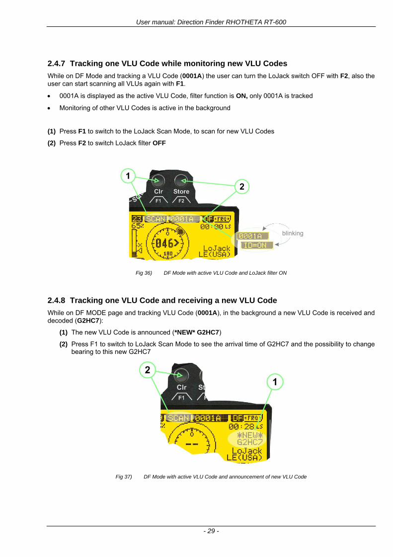
User manual Direction Finder RHOTHETA RT-600
- 29 -
247 Tracking one VLU Code while monitoring new VLU Codes
While on DF Mode and tracking a VLU Code (0001A) the user can turn the LoJack switch OFF with F2 also the user can start scanning all VLUs again with F1
0001A is displayed as the active VLU Code filter function is ON only 0001A is tracked
Monitoring of other VLU Codes is active in the background
(1) Press F1 to switch to the LoJack Scan Mode to scan for new VLU Codes
(2) Press F2 to switch LoJack filter OFF
Fig 36) DF Mode with active VLU Code and LoJack filter ON
248 Tracking one VLU Code and receiving a new VLU Code
While on DF MODE page and tracking VLU Code (0001A) in the background a new VLU Code is received and decoded (G2HC7)
(1) The new VLU Code is announced (NEW G2HC7)
(2) Press F1 to switch to LoJack Scan Mode to see the arrival time of G2HC7 and the possibility to change bearing to this new G2HC7
Fig 37) DF Mode with active VLU Code and announcement of new VLU Code
User manual Direction Finder RHOTHETA RT-600
- 30 -
249 Switching to a new VLU Code
While on the LoJack Scan Page tracking one VLU Code (0001A) and notified of a new VLU Code (G2HC7)
(1) press F1 to continue tracking 0001A
(2) press F2 to start tracking G2HC7
(3) Time elapsed since G2HC7 was last received
(4) Time elapsed since 0001A was last received
If F1 is pressed for 2 sec the indicated VLU Code (G2HC7) and ID (0001A) are deleted
Fig 38) LoJack Scan Page with one active VLU Code and one new VLU Code
2410 ldquoBlockingrdquo function of one LoJack VLU Code
The LoJack scan page can also be used to ldquoblockrdquo one unwanted LoJack VLU ID signal by separating the adjusted active ID from any other received LoJack VLU signal This is done by muting the audio (see example below) when a LoJack signal with VLU code ldquo0001Ardquo is received gtgt Any new VLU Code (active LoJack signal) - except for 0001A ndash will be displayed on the top row and generate the audible beep tone
Fig 39) LoJack Scan Page with one active VLU Code and audio OFF
Tip ldquoBlockingrdquo is an important tool for practical missions As example a stolen vehicle with VLU ID ldquo0001Ardquo was tracked in the DF bearing mode The mission
is completed but the VLU is normally still transmitting With the settings above only new VLU signals except the now unwanted ldquo0001Ardquo are audible and displayed in the upper (scan LoJack hellip for new VLU) box
User manual Direction Finder RHOTHETA RT-600
- 31 -
2411 Tracking in the 216 to 220 MHz band
The RT-600 features scanning and bearing functionality in the 216000 MHz to 220000 MHz band The 216000 MHz ndash 220000 MHz band contains frequencies and signals used by special services and tracked by law enforcement special ops and similar organizations These are some of the frequencies and services in this band
CFR 90259 tx 216000 MHz to 220000 MHz
Low Power Radio Service (LPRS) tx 216000 MHz to 217000 MHz
Medical beacons Project Lifesaver tx wristankle tx 213000 MHz to 216000 MHz
ETS tx stolen cashasset recovery tx ldquobaitrdquordquotagrdquo tx 216000 MHz to 220000 MHz tx = transmitter(s) However any future or current user of the Rhotheta RT-600 must be aware that tracking signals on the frequencies listed above may be challenging and even frustrating due mostly to negative factors in some of the transmitters
bull Very low RF power output
bull Inefficient antennas
bull Battery-powered devices with a ldquolow batteryrdquo condition
bull Devices worn or located in conditions of poor RF propagation
bull Devices with channel spacing different than the one specified for the RT-600
These factors can make it very difficult for the DF to receive the signal andor display an accurate bearing Disclaimer For the reasons explained above and even though the RT-600 features top performance in its class RHOTHETA does not offer - and is not to be held responsible for - any guaranteed minimum range or distance to a transmitter in this band
25 Setup Edit Page System settings are displayed in the setup page The functions described in this section should be used by trained personal only
Fig 40) Accessing the Setup Page
The setup page can be accessed by holding down the gtCLRlt (1) and gtREPlt (2) buttons simultaneously and in the same time performing a left-hand turn on the gtPagelt rotary switch (3)
User manual Direction Finder RHOTHETA RT-600
- 32 -
Fig 41) Setup Page
(1) gtStorelt push-button must be pressed in parallel if a value of a setting shall be modified If a value can
be modified the background stops to blink
(2) gtSelectlt rotary switch used to scroll through the menu options The value of the actually activated menu option is high-lighted with dark background and blinking
(3) gtValuelt rotary switch used to change values in menu options (gtStorelt (1) has to be pressed in parallel if a value shall be modified)
(4) gtSN-Ratiolt menu option representing the necessary Signal-To-Noise-Ratio (Difference between signal and noise level) used as criterion for the automatic squelch function Please refer to the chapter ldquoSquelch Operationrdquo for details Default value is 60 dB
(5) gtMounting Positionlt menu option to select Top- or Bottom-Mounting of the DF antenna In case of rooftop installation (eg on land vehicles) ldquoToprdquo shall be selected In case of bottom-down (upside-down) installation (eg on a helicopter) ldquoBotrdquo shall be selected If this option is not selected correctly all bearing values will be mirror-inverted
(6) gtBearing Offsetlt menu option to include a constant offset correction to the bearing indication Bearing values in degrees will be changed according to the offset value
(7) gtMaximum External Dimming Voltage for Legendslt menu option which sets the upper limit of the dimming input voltage for the legends-panel Range=[15 hellip 28]V
(8) gtMinimum External Dimming Voltage for Legendslt menu option which sets the lower limit of the dimming input voltage for the legends-panel Range=[15 hellip 28]V
(9) gtPagelt rotary switch to be turned right-hand to go back to the Direction Finder page A left-hand turn on this rotary switch will show up an additional service page with debug information used for system checks
(10) gtExtended Seriallt It is possible to enable or disable the extended serial data protocol Only of interest if serial data is used by any connected control units like moving maps or computers For detailed information see (Serial interface data protocol (short description)gt at page 46) If there are compatibility problems with already existing older remote control software it is recommended to switch OFF the extended serial data protocol
User manual Direction Finder RHOTHETA RT-600
- 33 -
3 Error messages If an internal error of the device is recognized a corresponding flashing error message will be shown in the DF pages
Fig 42) Error Messages
(1) Error message including error code (in brackets)
(2) Short description of the indicated error
In case of coincidence of various errors the error with the highest priority will be displayed
Error message Error location Reason
Error (12) VOLTDU
Main voltage supply Main Voltage input too low ( 100 V)
Error (11) NO AU
Connection antenna display or Antenna Unit
No serial data (RS485) from Antenna Unit No or damaged connection between antenna and display or damaged antenna unit
Error (10) BAD AU
Connection antenna display
Incompatibility or bad data connection between display and antenna
Error (9) BAD RU
Remote Unit Incompatibility or bad data connection between display and external serial Remote Unit or PC
Error (8) VOLTAU
Antenna Unit Voltage supply at Antenna Unit too low ( 90 V) Main voltage supply too low or considerable drop of voltage between display and antenna
Error (7) BAD DCU
Connection Display Antenna
Incompatibility or bad data connection between antenna and display
Error (6) NO DCU
Connection Display Antenna
No serial data from Display Control Unit to Antenna Unit
Error (5) PLL ERR
antenna Error in synthesizer-oscillator of receiver in Antenna Unit
Error (4) FRQ+OFS
received transmitter Received frequency too high (more than 6 KHz error of transmitter)
Error (3) FRQ-OFS
received transmitter received frequency too low (more than 6 KHZ error of transmitter)
Error (2) DECODE
radio distance transmitter DF
Data Bits of decoded signal (COSPAS-SARSAT or LoJack) defective
Error (1) DATARNG
Incompatibility of data DCU AU
Protocol data bytes out of valid range
Error (0) NO REC
Antenna Unit receiver
Receiver board defective
User manual Direction Finder RHOTHETA RT-600
- 34 -
4 Installation
41 Antenna unit A convenient position of the monopole bearing antenna is crucial for good bearing results The antenna needs an effective ground connection to the body of the aircraft or to the roof of the vehicle If there is no metallic mounting surface available a metallic sheet or similar (net) with connection to ground has to be applied first between vehicle-body and antenna In this hatched area the antenna touches the body ofthe vehicleaircraft In order to obtain a good groundconnection the surface of the body should be bared(Measuring unit [mm])
8 x holes for mounting the antenna unit to the
vehicle aircraft
Fig 43) Antenna Mounting Drawing
User manual Direction Finder RHOTHETA RT-600
- 35 -
411 Influence of antenna location and environment on the bearing accuracy
Recommendations concerning the practical antenna unit location on helicopters and airplanes
The bearing accuracy of the direction finder antenna unit is severely influenced (comparable to an airspeed sensor) by the environment For comparison a perfect high quality speed sensor will not indicate the true airspeed if this sensor is interfered by strong turbulences The direction finder antenna unit acts as a sensor for electromagnetic waves In the near field of this antenna unit any conductive (eg metallic) obstacle will influence the incoming wave field and create reflections which decrease the bearing accuracy These are general physical limitations concerning all types of direction finder systems To achieve the best bearing results it should be considered that the antenna unit is installed as far away as possible from any other vertically polarized conductive structure If possible there should be no reflectors within an area of 2-3 feet around the antenna unit In this worst case example the direction finder will not work properly
Fig 44) Antenna Installed in a Bad Location
In this example the antenna unit is located too close to the cable cutter of the helicopter This cutter will produce strong reflections especially as the length is equal to Lambda4 within the VHF airband
User manual Direction Finder RHOTHETA RT-600
- 36 -
Examples of properly installed direction finder antenna units
Fig 45) Antenna Installed in Good Locations
User manual Direction Finder RHOTHETA RT-600
- 37 -
42 Display and Control Unit
The display control unit may be mounted into a front panel by the means of this mounting drawing
Fig 46) DCU Mounting Drawing
(all dimensions in [mm]) To install or uninstall the display control unit perform the following steps (1) Remove the cover caps of the four rotary switches
(2) Loose the screws visible below the position of the cover caps
(3) Remove the plastic button from the axis of the four rotary switches
(4) Mount dismount the display control unit
(5) Re-install the plastic buttons on the axis of the four rotary switches
(6) Fix the screws so that the plastic buttons are fixed on the axis
(7) Re-install the cover caps on the four rotary switches
User manual Direction Finder RHOTHETA RT-600
- 38 -
43 System Interconnect Wiring Diagram (Also refer to chapter ldquoTechnical Datardquo for details)
Fig 47) System Interconnect Wiring Diagram
6-pol Amphenol plug femalePTG06SE10-6S(SQ)
max length of cable 20 m 9-pol Sub-D plug (femalemale)
User manual Direction Finder RHOTHETA RT-600
- 39 -
5 Technical Data
51 Electric features
Method of bearing Doppler-principle (3 kHz rotational frequency right left rotation)
Bearing accuracy1 plusmn 5deg RMS
Internal resolution 1deg
Bearing Sensitivity VHF AirEmergency le 25 μVm (typical)
VHF Marine le 25 μVm (typical)
UHF Emergency and ETS le 4 μVm (typical)
COSPAS-SARSAT le 4 μVm (typical)
LoJack Decoding (50 Message Error Rate) and bearing le 5 μVm (typical)
Frequency stability plusmn 20 ppm (Δff = plusmn210-6)
Reception frequencies
SAR version (Standard)
Frequency Options
VHF Emergency Band 118000 to 124000 MHz (833 kHz steps AM)
VHF Marine Band 154000 to 163000 MHz ( 500 kHz steps FM) (channel 16 selectable via channel no)
UHF Emergency Band 240000 to 246000 MHz (2500 kHz steps AM)
UHF FM Band 406100 to 410000 MHz ( 500 kHz steps FM)
COSPAS-SARSAT 400000 to 406092 MHz Including 406022 to 406076 MHz (Channel A S)
F1 VHF Air Band 118000 to 136992 MHz
F2 extended VHF Marine Band 137000 to 224995 MHz
F3 extended UHF Air Band 225000 to 399975 MHz
F4 additional UHF FM Band 406100 to 470000 MHz
Reception frequencies
LAW Enforcement version
Frequency Options
VHF Emergency Band 118000 to 124000 MHz (833 kHz steps AM)
VHF Marine Band 154000 to 163000 MHz (500 kHz steps FM) (channel 16 selectable via channel no)
LoJack 164000 to 174000 MHz (125 kHz steps FM)
ETS 216000 to 220000 MHz (10125 kHz AM)
COSPAS-SARSAT 400000 to 406092 MHz Including 406022 to 406076 MHz (Channel A S)
F1VHF Air Band 118000 to 136992 MHz
F2 extended VHF Marine Band 137000 to 163000 MHz
COSPAS-SARSAT fast scan mode
Full automatic detection of any active COSPAS-SARSAT channel A to S within 400 ms
COSPAS-SARSAT decoding
Reception and decoding of COSPAS-SARSAT data signal (112 or 144 bit) specified according to COSPAS-SARSAT
LoJack decoding Selectable LoJack ID display and selective active filtering
Special scanning modes
complete maritime ship band scanning within 3 s (channel 01 hellip 88 also frequencies between 2 channels are included)
1With undisturbed wave field and sufficient field strength Measuring by changing the angle of incidence with the antenna rotating on a revolving table in order to eliminate environmental influences on the results No modulation
User manual Direction Finder RHOTHETA RT-600
- 40 -
Bearable modulation A3E F3E A3X (ELT-modulation) F1D G2D COSPAS-SARSAT Bearing largely independent of modulation
Polarization Vertical
Polarization error 5deg at 60deg field vector rotation
Garbling cone Ca 30deg to the vertical
Time of response2 50 ms (with sufficient reception field strength)
LC-graphic display 128 x 64 pixels supertwist transflective extended range of temperature dark-blue display on yellow-green background background light Freely adjustable (exponential) dimming of brightness
NVG cockpit design Fully compatible NVIS Green B display Control Unit optional
Operating voltage 275 V nominal 12 V to 35 V DC
Current consumption LCD-background light Off max 500 mA (12 V DC) max 250 mA (24 V DC)
LCD-background light 100 max 750 mA (12 V DC) max 350 mA (24 V DC)
LCD-background light 100 max 900 mA (12 V DC) with NVG Option max 400 mA (24 V DC)
Audio out For external speaker approx 2 W (4 Ω)
Serial data interface Serial interface RS-232 (9600 baud 8 data bits 1 stop bit no parity)
2Very weak signals can considerably increase the time of response
User manual Direction Finder RHOTHETA RT-600
- 41 -
52 Interface External connections (optional at Sub-D 9-pol Male connector)
Dimming
Pin 8
external voltage input for variable dimming of legends
(optional)
Analog input signal for variable control of the legends illumination Input voltage range is freely adjustable in the range of 15 hellip 28 V in the setup menu Refer to chapter ldquoSetup Pagerdquo Default setting 8 hellip28 V (8 V = Off 28 V = max dimming for legends)
Input Impedance gt 50 k
Pin 6 night status line for LCD
dimming (optional)
Low-active (as example switch to ground) At input voltage lt 25 VDC the LCD dimming operates in nightNVG mode Maximum brightness ca 4 of daydefault mode brightness
Input Impedance gt 50 k
Pin 4 NVG status line for LCD
dimming (optional)
Low-active (as example switch to ground) At input voltage lt 25 VDC the LCD dimming operates in nightNVG mode Maximum brightness ca 4 of daydefault mode brightness
Input Impedance gt 50 k
AudioLF
Pin 7 Audio output signal
AC coupled voltage source with very low inner resistance Maximum output voltage ca 8 VPP = 283V RMS at maximum Volume Maximum output power ca 2 W with 4 speaker
If a headphone is connected ([32hellip600] 100mW) we recommend using a resistor (18 025 W) between audio output and headphone to prevent damage of the headphone
Serial interface RS232 (9600 baud 8 data bits 1 stop bit no parity)
Pin 3 TXD Serial output (ca plusmn10 V)
Pin 2 RXD Serial input (ca plusmn10 V)
User manual Direction Finder RHOTHETA RT-600
- 42 -
53 Mechanical features
Temperature range
Display Control Unit permissible operating temperature3 -20 degC +60 degC permissible storage temperature -30 degC +80 degC
Antenna Unit permissible operating temperature3 -40 degC +60 degC permissible storage temperature -55 degC +80 degC
Protective system Antenna Unit IP 67
Weights Display Control Unit 250 g Antenna Unit 2000 g
Dimensions Display Control Unit 82 mm x 82 mm x 43 mm (width x height x depth) Antenna Unit 270 mm x 185 mm
Fig 48) DCU Mechanical Drawing (all dimensions in [mm])
3 For temperatures lower than ndash10deg C a warm-up period of 15 min should be allowed
User manual Direction Finder RHOTHETA RT-600
- 43 -
Fig 49) AU Mechanical Drawing (all dimensions in [mm])
User manual Direction Finder RHOTHETA RT-600
- 44 -
6 Appendix
61 Frequency Ranges
User manual Direction Finder RHOTHETA RT-600
- 45 -
62 Frequencies of channels on maritime band (only for standard [A] version) Frequency-range of the RT-600 in the maritime band 156000 MHz 162025 MHz
Channel No frequency (ship - station) Frequency (coast - station)
1 156050 MHz 160650 MHz 2 156100 MHz 160700 MHz 3 156150 MHz 160750 MHz 4 156200 MHz 160800 MHz 5 156250 MHz 160850 MHz 6 156300 MHz 160900 MHz 7 156350 MHz 160950 MHz 8 156400 MHz 9 156450 MHz
10 156500 MHz 11 156550 MHz 12 156600 MHz 13 156650 MHz 14 156700 MHz 15 156750 MHz 16 156800 MHz 17 156850 MHz 18 156900 MHz 161500 MHz 19 156950 MHz 161550 MHz 20 157000 MHz 161600 MHz 21 157050 MHz 161650 MHz 22 157100 MHz 161700 MHz 23 157150 MHz 161750 MHz 24 157200 MHz 161800 MHz 25 157250 MHz 161850 MHz 26 157300 MHz 161900 MHz 27 157350 MHz 161950 MHz 28 157400 MHz 162000 MHz 60 156025 MHz 160625 MHz 61 156075 MHz 160675 MHz 62 156125 MHz 160725 MHz 63 156175 MHz 160775 MHz 64 156225 MHz 160825 MHz 65 156275 MHz 160875 MHz 66 156325 MHz 160925 MHz 67 156375 MHz 68 156425 MHz 69 156475 MHz 70 156525 MHz 71 156575 MHz 72 156625 MHz 73 156675 MHz 74 156725 MHz 75 156775 MHz 76 156825 MHz 77 156875 MHz 78 156925 MHz 161525 MHz 79 156975 MHz 161575 MHz 80 157025 MHz 161625 MHz 81 157075 MHz 161675 MHz 82 157125 MHz 161725 MHz 83 157175 MHz 161775 MHz 84 157225 MHz 161825 MHz 85 157275 MHz 161875 MHz 86 157325 MHz 161925 MHz 87 157375 MHz 161975 MHz 88 157425 MHz 162025 MHz
User manual Direction Finder RHOTHETA RT-600
- 46 -
63 Serial interface data protocol (short description)
631 General
Interface parameters RS232 9600 Baud 8 databits 1 stopbit no parity LSB sent first Timing of serial data For accurate use of the serial data (even for the optional serial input commands) the correct timing is mandatory The DCU (Display Control Unit) sends out via the RS-232 Pins (see 43 System Interconnect Wiring Diagram page 38) cyclic and autonomous every approx 250300 ms a binary data stream which contains all relevant DF-bearing information The output data contains one or two blocks of binary data (see next picture with accordingly description) The optional serial input is only used if changes (as example frequency change) are done by additional remote control units
Fig 50) Timing of serial data
Serial standard output
This output data is always available and contains all relevant DF-bearing data For detailed content see page 47
Optional extended serial output
This data contains some additional information like as example CospasSarsat or LoJack decoding and ID data For detailed content see page 50 The data is only available with DCU Software [Rev ge 320] and if this optional data block is configured as ON = enabled (see Setup Edit Page point (10) )
Even to avoid compatibility problems with already existing older remote control software it is possible to disable switch off this additional data block (see Setup Edit Page point (10) )
Optional serial input
Only used for optional commands to control DCU parameters If as example the direction finder frequency is changed remotely there is send to the DCU one time this data block with the new frequency For detailed content see page 52
User manual Direction Finder RHOTHETA RT-600
- 47 -
632 Serial standard output (protocol description)
Specification serial standard output
The binary data stream with a length of 39 bytes starts with a header byte (value = hex 0xA0 as ID for DF Mode) The next bytes contain different values for status bearing information and also service The last byte is used for data stream checksum control Remark This is a binary data protocol So every byte value from 0dec hellip 255dec (0x00 hellip 0xFF) is possible Because of this it is not allowed to realize a start byte detection by the content (0xA0) The idle line detection is recommended for detection the end of message Register of databytes (for details see next page)
byte no
[0] Header = 0xA0 Id for DF Mode
[1] Number = 39 = bytes in the complete message (including header and checksumbyte)
[2] Status (1) HSB [x|x|x|x|x|x|x|x] LSB | | | | | | | --gt (0) Receiving | | | | | | ----gt (1) Squelch controlled by AU (X) | | | | | ------gt (2) Permission RL Calibration | | | | --------gt (3) Line Night | | | ----------gt (4) Line NVG | | ------------gt (5) Dimming External | --------------gt (6) Autosquelch Active ----------------gt (7) 0=Standard Version 1=LE Version
[3] Status (2) HSB [x|x|x|x|x|x|x|x] LSB | ----------------gt (7) 0=Standard 1=extended serial dataprotocol = ONactive
[45] Error (Bits[120])
[6] Actual DCU Page
[7] Volume [0hellip100]
[811] Frequency [Hz]
[12] Active Band
[13] Actual Squelchlevel [0hellip60]
[14] Audio-Line amp_NF_Test Output
[15] (Not used)
[1617] Voltage_DCU ([0hellip335]=[0 hellip 335]V
[1819] Voltage_AU ([0hellip255]=[0 hellip 255]V
[20] Temperature_AU [-68hellip+127]degC
[21] Frequency Offset [-99hellip+99]
[2225] ServiceTest values (mode dependent test values for service only)
26 (Not used reserved)
[27] Level [0hellip100]
[2829] Bearing Averaged [0hellip359]deg relative
[3031] Bearing Live_Min [0hellip359]deg relative
[3233] Bearing Live_Max [0hellip359]deg relative
[34] Test Value PS-RAM Right Rotation[0hellip178] (for service only)
[35] Test Value PS-RAM Left Rotation [0hellip178] (for service only)
[3637] (Not used reserved)
[38] Checksum is the 2rsquos complement of the modulo-256 sum of all bytes without checksum-byte [0n-1]
User manual Direction Finder RHOTHETA RT-600
- 48 -
Detailed Description of important values for practical use
Status byte [2] Receiving Bit 0 of this value (LSB) indicates signal receiving Bit 0 = 0 then no signal is received and so on no bearing is available Bit 0 = 1 then bearing is possible Bit 1 if(1) then Squelch is controlled by AU (active at modes CospasSarsat Decode CospasSarsat Scanning LoJack with Filter=ID only)
Error bytes [4hellip5] 16 bit value each set bit corresponds to the error no (Refer to the chapter Error messages) Example - 0x0000 No error - 0x0800 Bit No 11 Set ( = No AU Error)
Actual DCU Page byte [6] indicates actual operating mode of DCU 0 = Standard bearing page 1 = Frequency memory page 2 = CospasSarsat decoding page 3 = LoJack decoding page (ID edit)
Frequency bytes [8hellip11] 32 bit value actual adjusted frequency [Hz] Example - 0x073DF160 1215000000 121500 MHz
Active Band Standard Version [A] 0=VHF Airband 1=VHF Marineband sea 2=VHF Marineband coast 3=UHV Airband 4=CospasSarsat LE Version [L] 0=VHF Airband 1=LoJack 2=Lifesaver 3=ETS 4=CospasSarsat
Actual Squelchlevel byte [13] Range [0hellip60] without signal the actual squelchlevel should always be adjusted a little bit over the noise level (Refer to the chapter Squelch operation)
Level byte [27] Range [099] actual receiving level (without signal this value is equal to the noise level) If a signal is received then this value corresponds to the signal strength of this signal
Relative Bearing averaged byte [2829] 16 bit value Range [0hellip359 0xFFFF] if the value = 0xFFFF then no valid bearing is available otherwise this value contains the actual averaged bearing information in Deg [0deg359deg] Example - 0X0114 276deg bearing (= left side oriented to heading)
Bearing Live MinMax byte[3031] amp [3233] - 16 bit values Range [0hellip359 0xFFFF] Only for signal quality or additional information ndash NOT recommended for bearing indication The relative live bearing field contains the maxmin bearing in degrees without averaging The relative live bearing reacts faster than the normal relative bearing but it has not the precision of the averaged bearing The MinMax Bearing Values are calculated within a time period of approx 250 ms If they are very close together (for example ldquo124rdquo and ldquo128rdquo degrees) then the signal quality is quite good A wide span of the minmax values (for example ldquo97rdquo and ldquo162rdquo) shows very noisy but nevertheless bearable signal quality
User manual Direction Finder RHOTHETA RT-600
- 49 -
633 DCU Info output (protocol description)
Specification DCU Info output
Remark This protocol is only available while the SetupEdit page is activated at the DCU
byte no
[0] Header = 0xAF Id for DCU Info Mode
[1] Number = 39 = bytes in the complete message (including header and checksumbyte)
[2]
(see standard output) [3]
[45]
[621] Info String of 15 byteschars the string contains Information about Unit Variant Software Version and Serial No
Example Byte [318] =
|--AU ID---||Var-||---Software Version---| |-------------- Serial No---------------| [0x44][0x55][0x41][0x33][0x2E][0x33][0x30][0x3A][0x20][0x20][0x30][0x31][0x32][0x33][0x34][0x00] rsquoDrsquo rsquoUrsquo rsquoArsquo rsquo3rsquo rsquorsquo rsquo3rsquo rsquo0rsquo rsquorsquo rsquo rsquo rsquo rsquo rsquo0rsquo rsquo1rsquo rsquo2rsquo rsquo3rsquo rsquo4rsquo rsquoENDrsquo | | | | __________________ | | ________________________ | n n n | | n n n n n | (Software Version) | | (Serial No) | gt rsquoArsquo = Standard Variant gt rsquoLrsquo = Law Enforcement Variant
User manual Direction Finder RHOTHETA RT-600
- 50 -
634 Optional extended serial output (protocol description)
The data content depends on the actual mode of the direction finder To get special data the direction finder has first to be switched to the equivalent mode
COSPAS-SARSAT Decoding data
This data is only available and valid if Display Control Unit with actual software Rev ge 320 (see Power-On procedure page 10) Configuration of Extended serial = ON (see Setup Edit Page point (10) ) Direction Finder COSPAS-SARSAT decoding mode is activated by selecting the corresponding page
(see COSPAS-SARSAT Decode Window page 20 and page 21) and so on Header (byte 0 of data) = 0x91
A valid COSPAS-SARSAT decoding data protocol is always marked by the first data byte (header = 0x91) Always after receiving and decoding of a valid COSPAS-SARSAT pulse the complete data protocol with 33 bytes is send out one time
Byte No
[0] Header = 0x91 (Identification for CPSarsat decoding mode)
[1] Number of bytes - 7 if no decoded pulse is available - 33 if new pulse was received and is available
[2] Error
[3] Bit[0] - 0 =gt No new 406 MSG (decoded data) available - 1 =gt New valid 406 MSG available (Sync amp Frame Ok) Check Error Status for Bit-Errors
Bit[61] AutoSquelch Level valid range [060] ( decimal)
Bit[7] = 1 Squelch controlled by AU
[4] Signallevel of received signal valid range [099] ( decimal)
[5] Voltage of Antenna Unit Power Supply input valid range [80255] (decimal = 80 255 V DC)
[6] Temperature inside Antenna Unit valid range [-50+100] (degC signed byte value)
The following databytes are only available if a correct CPSarsat puls gets received and decoded with correct checksum
[724] 18 x Databytes complete orginal CPSarsat 406 decoded message (144 bit)
Databyte Nr [ Byte 7 ] [ Byte 8 ] [Byte9 Byte24] 406 MSG Bit Nr [1 2 3 4 5 6 7 8] [9 10 11 12 13 14 15 16] [17 144]
[25] SN-Flag valid values 0x53=rsquoSrsquo 0x4E=rsquoNrsquo 0x2D=rsquo-rsquo if no GPS data available
GPS-Position Latitude
[26] Deg valid values [090] (decimal Deg) 0xFF if no GPS data available
[27] Min valid values [059] (decimal Deg) 0xFF if no GPS data available
[28] Sec valid values [059] (decimal Deg) 0xFF if no GPS data available
[29] WE-Flag valid values 0x57=rsquoWrsquo 0x45=rsquoErsquo 0x2D=rsquo-rsquo if no GPS data available
GPS-Position Longitude
[30] Deg valid values [0180] (decimal Deg) 0xFF if no GPS data available
[31] Min valid values [059] (decimal Deg) 0xFF if no GPS data available
[32] Sec valid values [059] (decimal Deg) 0xFF if no GPS data available
User manual Direction Finder RHOTHETA RT-600
- 51 -
LoJack ID data
This data is only available and valid if Display Control Unit with actual software Rev ge 320 (see Power-On procedure page 10) Direction Finder of variant [L] Law Enforcement Configuration of Extended serial = ON (see Setup Edit Page point (10) ) Direction Finder is working with active LoJack gtID Filterlt Header (byte 0 of data) = 0x93 or 0x94
Valid LoJack ID decoding data is always marked by the first data byte (header = 0x93 or 0x94)
Byte No
[0] Header = 0x93 LoJack ID editing sub-page is selected Filter = VLU all valid and received LoJack pulses are indicated = 0x94 Lojack Decode amp DF Mode with active Filter = ID
[1] Number of bytes in the complete data stream - decimal 26 = default value
[2] Nonrelevant
[3] Bit[0] Receiving OnOff - 0 =gt No Receiving no bearing - 1 =gt new LoJack pulse received
[412] Nonrelevant
[1317] Lojack ID
Replay Code 5 x ASCII Chars ldquoNo BIOZrdquo set
Example ASCII = ldquo000R1rdquo
18 Receiver Level Out Max [099]
19
LoJack Decoder Status [07] - 0 Off - 1 Wait for Preamble - 2 Preamble Ok - 3 FlagPattern Ok - 4 Data BitError gt 1 - 5 Data Ok (No VLU) - 6 VLU Ok - 7 ID Ok (Filter=IDONLY)
[2025] Nonrelevant
Remark Only if byte no [3] bit [0] gets ldquo1rdquo (Receiving On) then an active LoJack pulse is received and so on the corresponding LoJack ID valid otherwise the LoJack ID only shows the actual adjusted LoJack Filter ID of the direction finder
User manual Direction Finder RHOTHETA RT-600
- 52 -
635 Optional serial input (protocol description)
Specification serial input (optional)
The serial input is normally used for service and maintenance only Nevertheless it is possible via this interface to remote control the actual frequency and the squelchlevel of the DF system If a valid data stream is send to the DF then the actual frequency selection at the DCU is switched to Block2 AUX0 At this memory channel the new frequency is stored and used automatically (Refer to the chapter Frequency Selection Page) If the frequency is changed (by one valid data stream) no more serial input is necessary The actual frequency can be changed again at any time by manual operation at the DCU The timing of serial input (if used) is strictly fixed The optional serial input has to take place directly after a complete serial output (max 50 ms delay time) If a new changed frequency is commanded to the DCU via this serial input interface it can take up to 1 sec of time until this new frequency is ready for operationbearing It is strictly not recommended to use the frequency remote control for any scan mode The frequency control has to be used for static frequency change only Register of databytes
byte no
[0] Header 0xC0
[1] Number of bytes in the complete message (including header and checksumbyte)
[23] (not used for normal operation any byte values allowed)
[4] Volume [0100]
[58] Frequency [Hz] (frequency is rounded to the according grid automatically)
Valid Range for Standard Version Valid Range for LE Version
118000000 hellip 123000000 [Hz] 8333 kHz 118000000 hellip 123000000 [Hz] 8333 kHz
156050000 hellip 162025000 [Hz] 5000 kHz 164000000 hellip 174000000 [Hz] 8333 kHz
201000000 hellip 215995000 [Hz] 5000 kHz
240000000 hellip 246000000 [Hz] 8333 kHz 216000000 hellip 218995000 [Hz] 12500 kHz219000000 hellip 220000000 [Hz] 10000 kHz
400000000 hellip 410000000 [Hz] 8333 kHz 400000000 hellip 410000000 [Hz] 8333 kHz
[9] Squelchlevel Manual = [0hellip60] Autosql= [ -1] Warning use only for pulsed signals (as example CpSarsat LoJack)
[10] (not used for normal operation any byte values allowed)
[11] Internal Dimming [0100]
[12] Checksum is the 2rsquos complement of the modulo-256 sum of all bytes without checksum-byte [0n-1]
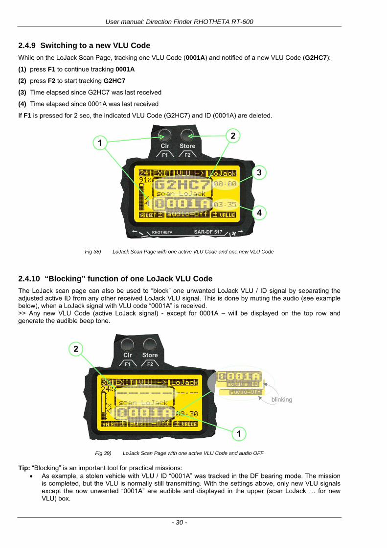
User manual Direction Finder RHOTHETA RT-600
- 30 -
249 Switching to a new VLU Code
While on the LoJack Scan Page tracking one VLU Code (0001A) and notified of a new VLU Code (G2HC7)
(1) press F1 to continue tracking 0001A
(2) press F2 to start tracking G2HC7
(3) Time elapsed since G2HC7 was last received
(4) Time elapsed since 0001A was last received
If F1 is pressed for 2 sec the indicated VLU Code (G2HC7) and ID (0001A) are deleted
Fig 38) LoJack Scan Page with one active VLU Code and one new VLU Code
2410 ldquoBlockingrdquo function of one LoJack VLU Code
The LoJack scan page can also be used to ldquoblockrdquo one unwanted LoJack VLU ID signal by separating the adjusted active ID from any other received LoJack VLU signal This is done by muting the audio (see example below) when a LoJack signal with VLU code ldquo0001Ardquo is received gtgt Any new VLU Code (active LoJack signal) - except for 0001A ndash will be displayed on the top row and generate the audible beep tone
Fig 39) LoJack Scan Page with one active VLU Code and audio OFF
Tip ldquoBlockingrdquo is an important tool for practical missions As example a stolen vehicle with VLU ID ldquo0001Ardquo was tracked in the DF bearing mode The mission
is completed but the VLU is normally still transmitting With the settings above only new VLU signals except the now unwanted ldquo0001Ardquo are audible and displayed in the upper (scan LoJack hellip for new VLU) box
User manual Direction Finder RHOTHETA RT-600
- 31 -
2411 Tracking in the 216 to 220 MHz band
The RT-600 features scanning and bearing functionality in the 216000 MHz to 220000 MHz band The 216000 MHz ndash 220000 MHz band contains frequencies and signals used by special services and tracked by law enforcement special ops and similar organizations These are some of the frequencies and services in this band
CFR 90259 tx 216000 MHz to 220000 MHz
Low Power Radio Service (LPRS) tx 216000 MHz to 217000 MHz
Medical beacons Project Lifesaver tx wristankle tx 213000 MHz to 216000 MHz
ETS tx stolen cashasset recovery tx ldquobaitrdquordquotagrdquo tx 216000 MHz to 220000 MHz tx = transmitter(s) However any future or current user of the Rhotheta RT-600 must be aware that tracking signals on the frequencies listed above may be challenging and even frustrating due mostly to negative factors in some of the transmitters
bull Very low RF power output
bull Inefficient antennas
bull Battery-powered devices with a ldquolow batteryrdquo condition
bull Devices worn or located in conditions of poor RF propagation
bull Devices with channel spacing different than the one specified for the RT-600
These factors can make it very difficult for the DF to receive the signal andor display an accurate bearing Disclaimer For the reasons explained above and even though the RT-600 features top performance in its class RHOTHETA does not offer - and is not to be held responsible for - any guaranteed minimum range or distance to a transmitter in this band
25 Setup Edit Page System settings are displayed in the setup page The functions described in this section should be used by trained personal only
Fig 40) Accessing the Setup Page
The setup page can be accessed by holding down the gtCLRlt (1) and gtREPlt (2) buttons simultaneously and in the same time performing a left-hand turn on the gtPagelt rotary switch (3)
User manual Direction Finder RHOTHETA RT-600
- 32 -
Fig 41) Setup Page
(1) gtStorelt push-button must be pressed in parallel if a value of a setting shall be modified If a value can
be modified the background stops to blink
(2) gtSelectlt rotary switch used to scroll through the menu options The value of the actually activated menu option is high-lighted with dark background and blinking
(3) gtValuelt rotary switch used to change values in menu options (gtStorelt (1) has to be pressed in parallel if a value shall be modified)
(4) gtSN-Ratiolt menu option representing the necessary Signal-To-Noise-Ratio (Difference between signal and noise level) used as criterion for the automatic squelch function Please refer to the chapter ldquoSquelch Operationrdquo for details Default value is 60 dB
(5) gtMounting Positionlt menu option to select Top- or Bottom-Mounting of the DF antenna In case of rooftop installation (eg on land vehicles) ldquoToprdquo shall be selected In case of bottom-down (upside-down) installation (eg on a helicopter) ldquoBotrdquo shall be selected If this option is not selected correctly all bearing values will be mirror-inverted
(6) gtBearing Offsetlt menu option to include a constant offset correction to the bearing indication Bearing values in degrees will be changed according to the offset value
(7) gtMaximum External Dimming Voltage for Legendslt menu option which sets the upper limit of the dimming input voltage for the legends-panel Range=[15 hellip 28]V
(8) gtMinimum External Dimming Voltage for Legendslt menu option which sets the lower limit of the dimming input voltage for the legends-panel Range=[15 hellip 28]V
(9) gtPagelt rotary switch to be turned right-hand to go back to the Direction Finder page A left-hand turn on this rotary switch will show up an additional service page with debug information used for system checks
(10) gtExtended Seriallt It is possible to enable or disable the extended serial data protocol Only of interest if serial data is used by any connected control units like moving maps or computers For detailed information see (Serial interface data protocol (short description)gt at page 46) If there are compatibility problems with already existing older remote control software it is recommended to switch OFF the extended serial data protocol
User manual Direction Finder RHOTHETA RT-600
- 33 -
3 Error messages If an internal error of the device is recognized a corresponding flashing error message will be shown in the DF pages
Fig 42) Error Messages
(1) Error message including error code (in brackets)
(2) Short description of the indicated error
In case of coincidence of various errors the error with the highest priority will be displayed
Error message Error location Reason
Error (12) VOLTDU
Main voltage supply Main Voltage input too low ( 100 V)
Error (11) NO AU
Connection antenna display or Antenna Unit
No serial data (RS485) from Antenna Unit No or damaged connection between antenna and display or damaged antenna unit
Error (10) BAD AU
Connection antenna display
Incompatibility or bad data connection between display and antenna
Error (9) BAD RU
Remote Unit Incompatibility or bad data connection between display and external serial Remote Unit or PC
Error (8) VOLTAU
Antenna Unit Voltage supply at Antenna Unit too low ( 90 V) Main voltage supply too low or considerable drop of voltage between display and antenna
Error (7) BAD DCU
Connection Display Antenna
Incompatibility or bad data connection between antenna and display
Error (6) NO DCU
Connection Display Antenna
No serial data from Display Control Unit to Antenna Unit
Error (5) PLL ERR
antenna Error in synthesizer-oscillator of receiver in Antenna Unit
Error (4) FRQ+OFS
received transmitter Received frequency too high (more than 6 KHz error of transmitter)
Error (3) FRQ-OFS
received transmitter received frequency too low (more than 6 KHZ error of transmitter)
Error (2) DECODE
radio distance transmitter DF
Data Bits of decoded signal (COSPAS-SARSAT or LoJack) defective
Error (1) DATARNG
Incompatibility of data DCU AU
Protocol data bytes out of valid range
Error (0) NO REC
Antenna Unit receiver
Receiver board defective
User manual Direction Finder RHOTHETA RT-600
- 34 -
4 Installation
41 Antenna unit A convenient position of the monopole bearing antenna is crucial for good bearing results The antenna needs an effective ground connection to the body of the aircraft or to the roof of the vehicle If there is no metallic mounting surface available a metallic sheet or similar (net) with connection to ground has to be applied first between vehicle-body and antenna In this hatched area the antenna touches the body ofthe vehicleaircraft In order to obtain a good groundconnection the surface of the body should be bared(Measuring unit [mm])
8 x holes for mounting the antenna unit to the
vehicle aircraft
Fig 43) Antenna Mounting Drawing
User manual Direction Finder RHOTHETA RT-600
- 35 -
411 Influence of antenna location and environment on the bearing accuracy
Recommendations concerning the practical antenna unit location on helicopters and airplanes
The bearing accuracy of the direction finder antenna unit is severely influenced (comparable to an airspeed sensor) by the environment For comparison a perfect high quality speed sensor will not indicate the true airspeed if this sensor is interfered by strong turbulences The direction finder antenna unit acts as a sensor for electromagnetic waves In the near field of this antenna unit any conductive (eg metallic) obstacle will influence the incoming wave field and create reflections which decrease the bearing accuracy These are general physical limitations concerning all types of direction finder systems To achieve the best bearing results it should be considered that the antenna unit is installed as far away as possible from any other vertically polarized conductive structure If possible there should be no reflectors within an area of 2-3 feet around the antenna unit In this worst case example the direction finder will not work properly
Fig 44) Antenna Installed in a Bad Location
In this example the antenna unit is located too close to the cable cutter of the helicopter This cutter will produce strong reflections especially as the length is equal to Lambda4 within the VHF airband
User manual Direction Finder RHOTHETA RT-600
- 36 -
Examples of properly installed direction finder antenna units
Fig 45) Antenna Installed in Good Locations
User manual Direction Finder RHOTHETA RT-600
- 37 -
42 Display and Control Unit
The display control unit may be mounted into a front panel by the means of this mounting drawing
Fig 46) DCU Mounting Drawing
(all dimensions in [mm]) To install or uninstall the display control unit perform the following steps (1) Remove the cover caps of the four rotary switches
(2) Loose the screws visible below the position of the cover caps
(3) Remove the plastic button from the axis of the four rotary switches
(4) Mount dismount the display control unit
(5) Re-install the plastic buttons on the axis of the four rotary switches
(6) Fix the screws so that the plastic buttons are fixed on the axis
(7) Re-install the cover caps on the four rotary switches
User manual Direction Finder RHOTHETA RT-600
- 38 -
43 System Interconnect Wiring Diagram (Also refer to chapter ldquoTechnical Datardquo for details)
Fig 47) System Interconnect Wiring Diagram
6-pol Amphenol plug femalePTG06SE10-6S(SQ)
max length of cable 20 m 9-pol Sub-D plug (femalemale)
User manual Direction Finder RHOTHETA RT-600
- 39 -
5 Technical Data
51 Electric features
Method of bearing Doppler-principle (3 kHz rotational frequency right left rotation)
Bearing accuracy1 plusmn 5deg RMS
Internal resolution 1deg
Bearing Sensitivity VHF AirEmergency le 25 μVm (typical)
VHF Marine le 25 μVm (typical)
UHF Emergency and ETS le 4 μVm (typical)
COSPAS-SARSAT le 4 μVm (typical)
LoJack Decoding (50 Message Error Rate) and bearing le 5 μVm (typical)
Frequency stability plusmn 20 ppm (Δff = plusmn210-6)
Reception frequencies
SAR version (Standard)
Frequency Options
VHF Emergency Band 118000 to 124000 MHz (833 kHz steps AM)
VHF Marine Band 154000 to 163000 MHz ( 500 kHz steps FM) (channel 16 selectable via channel no)
UHF Emergency Band 240000 to 246000 MHz (2500 kHz steps AM)
UHF FM Band 406100 to 410000 MHz ( 500 kHz steps FM)
COSPAS-SARSAT 400000 to 406092 MHz Including 406022 to 406076 MHz (Channel A S)
F1 VHF Air Band 118000 to 136992 MHz
F2 extended VHF Marine Band 137000 to 224995 MHz
F3 extended UHF Air Band 225000 to 399975 MHz
F4 additional UHF FM Band 406100 to 470000 MHz
Reception frequencies
LAW Enforcement version
Frequency Options
VHF Emergency Band 118000 to 124000 MHz (833 kHz steps AM)
VHF Marine Band 154000 to 163000 MHz (500 kHz steps FM) (channel 16 selectable via channel no)
LoJack 164000 to 174000 MHz (125 kHz steps FM)
ETS 216000 to 220000 MHz (10125 kHz AM)
COSPAS-SARSAT 400000 to 406092 MHz Including 406022 to 406076 MHz (Channel A S)
F1VHF Air Band 118000 to 136992 MHz
F2 extended VHF Marine Band 137000 to 163000 MHz
COSPAS-SARSAT fast scan mode
Full automatic detection of any active COSPAS-SARSAT channel A to S within 400 ms
COSPAS-SARSAT decoding
Reception and decoding of COSPAS-SARSAT data signal (112 or 144 bit) specified according to COSPAS-SARSAT
LoJack decoding Selectable LoJack ID display and selective active filtering
Special scanning modes
complete maritime ship band scanning within 3 s (channel 01 hellip 88 also frequencies between 2 channels are included)
1With undisturbed wave field and sufficient field strength Measuring by changing the angle of incidence with the antenna rotating on a revolving table in order to eliminate environmental influences on the results No modulation
User manual Direction Finder RHOTHETA RT-600
- 40 -
Bearable modulation A3E F3E A3X (ELT-modulation) F1D G2D COSPAS-SARSAT Bearing largely independent of modulation
Polarization Vertical
Polarization error 5deg at 60deg field vector rotation
Garbling cone Ca 30deg to the vertical
Time of response2 50 ms (with sufficient reception field strength)
LC-graphic display 128 x 64 pixels supertwist transflective extended range of temperature dark-blue display on yellow-green background background light Freely adjustable (exponential) dimming of brightness
NVG cockpit design Fully compatible NVIS Green B display Control Unit optional
Operating voltage 275 V nominal 12 V to 35 V DC
Current consumption LCD-background light Off max 500 mA (12 V DC) max 250 mA (24 V DC)
LCD-background light 100 max 750 mA (12 V DC) max 350 mA (24 V DC)
LCD-background light 100 max 900 mA (12 V DC) with NVG Option max 400 mA (24 V DC)
Audio out For external speaker approx 2 W (4 Ω)
Serial data interface Serial interface RS-232 (9600 baud 8 data bits 1 stop bit no parity)
2Very weak signals can considerably increase the time of response
User manual Direction Finder RHOTHETA RT-600
- 41 -
52 Interface External connections (optional at Sub-D 9-pol Male connector)
Dimming
Pin 8
external voltage input for variable dimming of legends
(optional)
Analog input signal for variable control of the legends illumination Input voltage range is freely adjustable in the range of 15 hellip 28 V in the setup menu Refer to chapter ldquoSetup Pagerdquo Default setting 8 hellip28 V (8 V = Off 28 V = max dimming for legends)
Input Impedance gt 50 k
Pin 6 night status line for LCD
dimming (optional)
Low-active (as example switch to ground) At input voltage lt 25 VDC the LCD dimming operates in nightNVG mode Maximum brightness ca 4 of daydefault mode brightness
Input Impedance gt 50 k
Pin 4 NVG status line for LCD
dimming (optional)
Low-active (as example switch to ground) At input voltage lt 25 VDC the LCD dimming operates in nightNVG mode Maximum brightness ca 4 of daydefault mode brightness
Input Impedance gt 50 k
AudioLF
Pin 7 Audio output signal
AC coupled voltage source with very low inner resistance Maximum output voltage ca 8 VPP = 283V RMS at maximum Volume Maximum output power ca 2 W with 4 speaker
If a headphone is connected ([32hellip600] 100mW) we recommend using a resistor (18 025 W) between audio output and headphone to prevent damage of the headphone
Serial interface RS232 (9600 baud 8 data bits 1 stop bit no parity)
Pin 3 TXD Serial output (ca plusmn10 V)
Pin 2 RXD Serial input (ca plusmn10 V)
User manual Direction Finder RHOTHETA RT-600
- 42 -
53 Mechanical features
Temperature range
Display Control Unit permissible operating temperature3 -20 degC +60 degC permissible storage temperature -30 degC +80 degC
Antenna Unit permissible operating temperature3 -40 degC +60 degC permissible storage temperature -55 degC +80 degC
Protective system Antenna Unit IP 67
Weights Display Control Unit 250 g Antenna Unit 2000 g
Dimensions Display Control Unit 82 mm x 82 mm x 43 mm (width x height x depth) Antenna Unit 270 mm x 185 mm
Fig 48) DCU Mechanical Drawing (all dimensions in [mm])
3 For temperatures lower than ndash10deg C a warm-up period of 15 min should be allowed
User manual Direction Finder RHOTHETA RT-600
- 43 -
Fig 49) AU Mechanical Drawing (all dimensions in [mm])
User manual Direction Finder RHOTHETA RT-600
- 44 -
6 Appendix
61 Frequency Ranges
User manual Direction Finder RHOTHETA RT-600
- 45 -
62 Frequencies of channels on maritime band (only for standard [A] version) Frequency-range of the RT-600 in the maritime band 156000 MHz 162025 MHz
Channel No frequency (ship - station) Frequency (coast - station)
1 156050 MHz 160650 MHz 2 156100 MHz 160700 MHz 3 156150 MHz 160750 MHz 4 156200 MHz 160800 MHz 5 156250 MHz 160850 MHz 6 156300 MHz 160900 MHz 7 156350 MHz 160950 MHz 8 156400 MHz 9 156450 MHz
10 156500 MHz 11 156550 MHz 12 156600 MHz 13 156650 MHz 14 156700 MHz 15 156750 MHz 16 156800 MHz 17 156850 MHz 18 156900 MHz 161500 MHz 19 156950 MHz 161550 MHz 20 157000 MHz 161600 MHz 21 157050 MHz 161650 MHz 22 157100 MHz 161700 MHz 23 157150 MHz 161750 MHz 24 157200 MHz 161800 MHz 25 157250 MHz 161850 MHz 26 157300 MHz 161900 MHz 27 157350 MHz 161950 MHz 28 157400 MHz 162000 MHz 60 156025 MHz 160625 MHz 61 156075 MHz 160675 MHz 62 156125 MHz 160725 MHz 63 156175 MHz 160775 MHz 64 156225 MHz 160825 MHz 65 156275 MHz 160875 MHz 66 156325 MHz 160925 MHz 67 156375 MHz 68 156425 MHz 69 156475 MHz 70 156525 MHz 71 156575 MHz 72 156625 MHz 73 156675 MHz 74 156725 MHz 75 156775 MHz 76 156825 MHz 77 156875 MHz 78 156925 MHz 161525 MHz 79 156975 MHz 161575 MHz 80 157025 MHz 161625 MHz 81 157075 MHz 161675 MHz 82 157125 MHz 161725 MHz 83 157175 MHz 161775 MHz 84 157225 MHz 161825 MHz 85 157275 MHz 161875 MHz 86 157325 MHz 161925 MHz 87 157375 MHz 161975 MHz 88 157425 MHz 162025 MHz
User manual Direction Finder RHOTHETA RT-600
- 46 -
63 Serial interface data protocol (short description)
631 General
Interface parameters RS232 9600 Baud 8 databits 1 stopbit no parity LSB sent first Timing of serial data For accurate use of the serial data (even for the optional serial input commands) the correct timing is mandatory The DCU (Display Control Unit) sends out via the RS-232 Pins (see 43 System Interconnect Wiring Diagram page 38) cyclic and autonomous every approx 250300 ms a binary data stream which contains all relevant DF-bearing information The output data contains one or two blocks of binary data (see next picture with accordingly description) The optional serial input is only used if changes (as example frequency change) are done by additional remote control units
Fig 50) Timing of serial data
Serial standard output
This output data is always available and contains all relevant DF-bearing data For detailed content see page 47
Optional extended serial output
This data contains some additional information like as example CospasSarsat or LoJack decoding and ID data For detailed content see page 50 The data is only available with DCU Software [Rev ge 320] and if this optional data block is configured as ON = enabled (see Setup Edit Page point (10) )
Even to avoid compatibility problems with already existing older remote control software it is possible to disable switch off this additional data block (see Setup Edit Page point (10) )
Optional serial input
Only used for optional commands to control DCU parameters If as example the direction finder frequency is changed remotely there is send to the DCU one time this data block with the new frequency For detailed content see page 52
User manual Direction Finder RHOTHETA RT-600
- 47 -
632 Serial standard output (protocol description)
Specification serial standard output
The binary data stream with a length of 39 bytes starts with a header byte (value = hex 0xA0 as ID for DF Mode) The next bytes contain different values for status bearing information and also service The last byte is used for data stream checksum control Remark This is a binary data protocol So every byte value from 0dec hellip 255dec (0x00 hellip 0xFF) is possible Because of this it is not allowed to realize a start byte detection by the content (0xA0) The idle line detection is recommended for detection the end of message Register of databytes (for details see next page)
byte no
[0] Header = 0xA0 Id for DF Mode
[1] Number = 39 = bytes in the complete message (including header and checksumbyte)
[2] Status (1) HSB [x|x|x|x|x|x|x|x] LSB | | | | | | | --gt (0) Receiving | | | | | | ----gt (1) Squelch controlled by AU (X) | | | | | ------gt (2) Permission RL Calibration | | | | --------gt (3) Line Night | | | ----------gt (4) Line NVG | | ------------gt (5) Dimming External | --------------gt (6) Autosquelch Active ----------------gt (7) 0=Standard Version 1=LE Version
[3] Status (2) HSB [x|x|x|x|x|x|x|x] LSB | ----------------gt (7) 0=Standard 1=extended serial dataprotocol = ONactive
[45] Error (Bits[120])
[6] Actual DCU Page
[7] Volume [0hellip100]
[811] Frequency [Hz]
[12] Active Band
[13] Actual Squelchlevel [0hellip60]
[14] Audio-Line amp_NF_Test Output
[15] (Not used)
[1617] Voltage_DCU ([0hellip335]=[0 hellip 335]V
[1819] Voltage_AU ([0hellip255]=[0 hellip 255]V
[20] Temperature_AU [-68hellip+127]degC
[21] Frequency Offset [-99hellip+99]
[2225] ServiceTest values (mode dependent test values for service only)
26 (Not used reserved)
[27] Level [0hellip100]
[2829] Bearing Averaged [0hellip359]deg relative
[3031] Bearing Live_Min [0hellip359]deg relative
[3233] Bearing Live_Max [0hellip359]deg relative
[34] Test Value PS-RAM Right Rotation[0hellip178] (for service only)
[35] Test Value PS-RAM Left Rotation [0hellip178] (for service only)
[3637] (Not used reserved)
[38] Checksum is the 2rsquos complement of the modulo-256 sum of all bytes without checksum-byte [0n-1]
User manual Direction Finder RHOTHETA RT-600
- 48 -
Detailed Description of important values for practical use
Status byte [2] Receiving Bit 0 of this value (LSB) indicates signal receiving Bit 0 = 0 then no signal is received and so on no bearing is available Bit 0 = 1 then bearing is possible Bit 1 if(1) then Squelch is controlled by AU (active at modes CospasSarsat Decode CospasSarsat Scanning LoJack with Filter=ID only)
Error bytes [4hellip5] 16 bit value each set bit corresponds to the error no (Refer to the chapter Error messages) Example - 0x0000 No error - 0x0800 Bit No 11 Set ( = No AU Error)
Actual DCU Page byte [6] indicates actual operating mode of DCU 0 = Standard bearing page 1 = Frequency memory page 2 = CospasSarsat decoding page 3 = LoJack decoding page (ID edit)
Frequency bytes [8hellip11] 32 bit value actual adjusted frequency [Hz] Example - 0x073DF160 1215000000 121500 MHz
Active Band Standard Version [A] 0=VHF Airband 1=VHF Marineband sea 2=VHF Marineband coast 3=UHV Airband 4=CospasSarsat LE Version [L] 0=VHF Airband 1=LoJack 2=Lifesaver 3=ETS 4=CospasSarsat
Actual Squelchlevel byte [13] Range [0hellip60] without signal the actual squelchlevel should always be adjusted a little bit over the noise level (Refer to the chapter Squelch operation)
Level byte [27] Range [099] actual receiving level (without signal this value is equal to the noise level) If a signal is received then this value corresponds to the signal strength of this signal
Relative Bearing averaged byte [2829] 16 bit value Range [0hellip359 0xFFFF] if the value = 0xFFFF then no valid bearing is available otherwise this value contains the actual averaged bearing information in Deg [0deg359deg] Example - 0X0114 276deg bearing (= left side oriented to heading)
Bearing Live MinMax byte[3031] amp [3233] - 16 bit values Range [0hellip359 0xFFFF] Only for signal quality or additional information ndash NOT recommended for bearing indication The relative live bearing field contains the maxmin bearing in degrees without averaging The relative live bearing reacts faster than the normal relative bearing but it has not the precision of the averaged bearing The MinMax Bearing Values are calculated within a time period of approx 250 ms If they are very close together (for example ldquo124rdquo and ldquo128rdquo degrees) then the signal quality is quite good A wide span of the minmax values (for example ldquo97rdquo and ldquo162rdquo) shows very noisy but nevertheless bearable signal quality
User manual Direction Finder RHOTHETA RT-600
- 49 -
633 DCU Info output (protocol description)
Specification DCU Info output
Remark This protocol is only available while the SetupEdit page is activated at the DCU
byte no
[0] Header = 0xAF Id for DCU Info Mode
[1] Number = 39 = bytes in the complete message (including header and checksumbyte)
[2]
(see standard output) [3]
[45]
[621] Info String of 15 byteschars the string contains Information about Unit Variant Software Version and Serial No
Example Byte [318] =
|--AU ID---||Var-||---Software Version---| |-------------- Serial No---------------| [0x44][0x55][0x41][0x33][0x2E][0x33][0x30][0x3A][0x20][0x20][0x30][0x31][0x32][0x33][0x34][0x00] rsquoDrsquo rsquoUrsquo rsquoArsquo rsquo3rsquo rsquorsquo rsquo3rsquo rsquo0rsquo rsquorsquo rsquo rsquo rsquo rsquo rsquo0rsquo rsquo1rsquo rsquo2rsquo rsquo3rsquo rsquo4rsquo rsquoENDrsquo | | | | __________________ | | ________________________ | n n n | | n n n n n | (Software Version) | | (Serial No) | gt rsquoArsquo = Standard Variant gt rsquoLrsquo = Law Enforcement Variant
User manual Direction Finder RHOTHETA RT-600
- 50 -
634 Optional extended serial output (protocol description)
The data content depends on the actual mode of the direction finder To get special data the direction finder has first to be switched to the equivalent mode
COSPAS-SARSAT Decoding data
This data is only available and valid if Display Control Unit with actual software Rev ge 320 (see Power-On procedure page 10) Configuration of Extended serial = ON (see Setup Edit Page point (10) ) Direction Finder COSPAS-SARSAT decoding mode is activated by selecting the corresponding page
(see COSPAS-SARSAT Decode Window page 20 and page 21) and so on Header (byte 0 of data) = 0x91
A valid COSPAS-SARSAT decoding data protocol is always marked by the first data byte (header = 0x91) Always after receiving and decoding of a valid COSPAS-SARSAT pulse the complete data protocol with 33 bytes is send out one time
Byte No
[0] Header = 0x91 (Identification for CPSarsat decoding mode)
[1] Number of bytes - 7 if no decoded pulse is available - 33 if new pulse was received and is available
[2] Error
[3] Bit[0] - 0 =gt No new 406 MSG (decoded data) available - 1 =gt New valid 406 MSG available (Sync amp Frame Ok) Check Error Status for Bit-Errors
Bit[61] AutoSquelch Level valid range [060] ( decimal)
Bit[7] = 1 Squelch controlled by AU
[4] Signallevel of received signal valid range [099] ( decimal)
[5] Voltage of Antenna Unit Power Supply input valid range [80255] (decimal = 80 255 V DC)
[6] Temperature inside Antenna Unit valid range [-50+100] (degC signed byte value)
The following databytes are only available if a correct CPSarsat puls gets received and decoded with correct checksum
[724] 18 x Databytes complete orginal CPSarsat 406 decoded message (144 bit)
Databyte Nr [ Byte 7 ] [ Byte 8 ] [Byte9 Byte24] 406 MSG Bit Nr [1 2 3 4 5 6 7 8] [9 10 11 12 13 14 15 16] [17 144]
[25] SN-Flag valid values 0x53=rsquoSrsquo 0x4E=rsquoNrsquo 0x2D=rsquo-rsquo if no GPS data available
GPS-Position Latitude
[26] Deg valid values [090] (decimal Deg) 0xFF if no GPS data available
[27] Min valid values [059] (decimal Deg) 0xFF if no GPS data available
[28] Sec valid values [059] (decimal Deg) 0xFF if no GPS data available
[29] WE-Flag valid values 0x57=rsquoWrsquo 0x45=rsquoErsquo 0x2D=rsquo-rsquo if no GPS data available
GPS-Position Longitude
[30] Deg valid values [0180] (decimal Deg) 0xFF if no GPS data available
[31] Min valid values [059] (decimal Deg) 0xFF if no GPS data available
[32] Sec valid values [059] (decimal Deg) 0xFF if no GPS data available
User manual Direction Finder RHOTHETA RT-600
- 51 -
LoJack ID data
This data is only available and valid if Display Control Unit with actual software Rev ge 320 (see Power-On procedure page 10) Direction Finder of variant [L] Law Enforcement Configuration of Extended serial = ON (see Setup Edit Page point (10) ) Direction Finder is working with active LoJack gtID Filterlt Header (byte 0 of data) = 0x93 or 0x94
Valid LoJack ID decoding data is always marked by the first data byte (header = 0x93 or 0x94)
Byte No
[0] Header = 0x93 LoJack ID editing sub-page is selected Filter = VLU all valid and received LoJack pulses are indicated = 0x94 Lojack Decode amp DF Mode with active Filter = ID
[1] Number of bytes in the complete data stream - decimal 26 = default value
[2] Nonrelevant
[3] Bit[0] Receiving OnOff - 0 =gt No Receiving no bearing - 1 =gt new LoJack pulse received
[412] Nonrelevant
[1317] Lojack ID
Replay Code 5 x ASCII Chars ldquoNo BIOZrdquo set
Example ASCII = ldquo000R1rdquo
18 Receiver Level Out Max [099]
19
LoJack Decoder Status [07] - 0 Off - 1 Wait for Preamble - 2 Preamble Ok - 3 FlagPattern Ok - 4 Data BitError gt 1 - 5 Data Ok (No VLU) - 6 VLU Ok - 7 ID Ok (Filter=IDONLY)
[2025] Nonrelevant
Remark Only if byte no [3] bit [0] gets ldquo1rdquo (Receiving On) then an active LoJack pulse is received and so on the corresponding LoJack ID valid otherwise the LoJack ID only shows the actual adjusted LoJack Filter ID of the direction finder
User manual Direction Finder RHOTHETA RT-600
- 52 -
635 Optional serial input (protocol description)
Specification serial input (optional)
The serial input is normally used for service and maintenance only Nevertheless it is possible via this interface to remote control the actual frequency and the squelchlevel of the DF system If a valid data stream is send to the DF then the actual frequency selection at the DCU is switched to Block2 AUX0 At this memory channel the new frequency is stored and used automatically (Refer to the chapter Frequency Selection Page) If the frequency is changed (by one valid data stream) no more serial input is necessary The actual frequency can be changed again at any time by manual operation at the DCU The timing of serial input (if used) is strictly fixed The optional serial input has to take place directly after a complete serial output (max 50 ms delay time) If a new changed frequency is commanded to the DCU via this serial input interface it can take up to 1 sec of time until this new frequency is ready for operationbearing It is strictly not recommended to use the frequency remote control for any scan mode The frequency control has to be used for static frequency change only Register of databytes
byte no
[0] Header 0xC0
[1] Number of bytes in the complete message (including header and checksumbyte)
[23] (not used for normal operation any byte values allowed)
[4] Volume [0100]
[58] Frequency [Hz] (frequency is rounded to the according grid automatically)
Valid Range for Standard Version Valid Range for LE Version
118000000 hellip 123000000 [Hz] 8333 kHz 118000000 hellip 123000000 [Hz] 8333 kHz
156050000 hellip 162025000 [Hz] 5000 kHz 164000000 hellip 174000000 [Hz] 8333 kHz
201000000 hellip 215995000 [Hz] 5000 kHz
240000000 hellip 246000000 [Hz] 8333 kHz 216000000 hellip 218995000 [Hz] 12500 kHz219000000 hellip 220000000 [Hz] 10000 kHz
400000000 hellip 410000000 [Hz] 8333 kHz 400000000 hellip 410000000 [Hz] 8333 kHz
[9] Squelchlevel Manual = [0hellip60] Autosql= [ -1] Warning use only for pulsed signals (as example CpSarsat LoJack)
[10] (not used for normal operation any byte values allowed)
[11] Internal Dimming [0100]
[12] Checksum is the 2rsquos complement of the modulo-256 sum of all bytes without checksum-byte [0n-1]
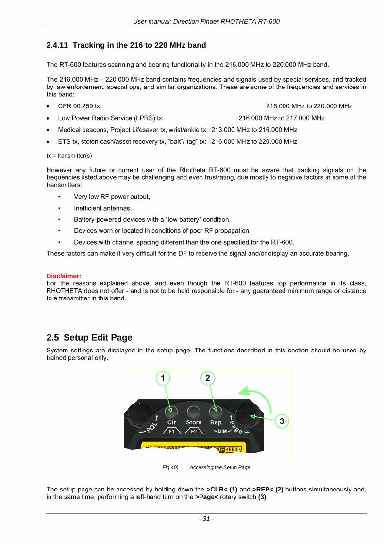
User manual Direction Finder RHOTHETA RT-600
- 31 -
2411 Tracking in the 216 to 220 MHz band
The RT-600 features scanning and bearing functionality in the 216000 MHz to 220000 MHz band The 216000 MHz ndash 220000 MHz band contains frequencies and signals used by special services and tracked by law enforcement special ops and similar organizations These are some of the frequencies and services in this band
CFR 90259 tx 216000 MHz to 220000 MHz
Low Power Radio Service (LPRS) tx 216000 MHz to 217000 MHz
Medical beacons Project Lifesaver tx wristankle tx 213000 MHz to 216000 MHz
ETS tx stolen cashasset recovery tx ldquobaitrdquordquotagrdquo tx 216000 MHz to 220000 MHz tx = transmitter(s) However any future or current user of the Rhotheta RT-600 must be aware that tracking signals on the frequencies listed above may be challenging and even frustrating due mostly to negative factors in some of the transmitters
bull Very low RF power output
bull Inefficient antennas
bull Battery-powered devices with a ldquolow batteryrdquo condition
bull Devices worn or located in conditions of poor RF propagation
bull Devices with channel spacing different than the one specified for the RT-600
These factors can make it very difficult for the DF to receive the signal andor display an accurate bearing Disclaimer For the reasons explained above and even though the RT-600 features top performance in its class RHOTHETA does not offer - and is not to be held responsible for - any guaranteed minimum range or distance to a transmitter in this band
25 Setup Edit Page System settings are displayed in the setup page The functions described in this section should be used by trained personal only
Fig 40) Accessing the Setup Page
The setup page can be accessed by holding down the gtCLRlt (1) and gtREPlt (2) buttons simultaneously and in the same time performing a left-hand turn on the gtPagelt rotary switch (3)
User manual Direction Finder RHOTHETA RT-600
- 32 -
Fig 41) Setup Page
(1) gtStorelt push-button must be pressed in parallel if a value of a setting shall be modified If a value can
be modified the background stops to blink
(2) gtSelectlt rotary switch used to scroll through the menu options The value of the actually activated menu option is high-lighted with dark background and blinking
(3) gtValuelt rotary switch used to change values in menu options (gtStorelt (1) has to be pressed in parallel if a value shall be modified)
(4) gtSN-Ratiolt menu option representing the necessary Signal-To-Noise-Ratio (Difference between signal and noise level) used as criterion for the automatic squelch function Please refer to the chapter ldquoSquelch Operationrdquo for details Default value is 60 dB
(5) gtMounting Positionlt menu option to select Top- or Bottom-Mounting of the DF antenna In case of rooftop installation (eg on land vehicles) ldquoToprdquo shall be selected In case of bottom-down (upside-down) installation (eg on a helicopter) ldquoBotrdquo shall be selected If this option is not selected correctly all bearing values will be mirror-inverted
(6) gtBearing Offsetlt menu option to include a constant offset correction to the bearing indication Bearing values in degrees will be changed according to the offset value
(7) gtMaximum External Dimming Voltage for Legendslt menu option which sets the upper limit of the dimming input voltage for the legends-panel Range=[15 hellip 28]V
(8) gtMinimum External Dimming Voltage for Legendslt menu option which sets the lower limit of the dimming input voltage for the legends-panel Range=[15 hellip 28]V
(9) gtPagelt rotary switch to be turned right-hand to go back to the Direction Finder page A left-hand turn on this rotary switch will show up an additional service page with debug information used for system checks
(10) gtExtended Seriallt It is possible to enable or disable the extended serial data protocol Only of interest if serial data is used by any connected control units like moving maps or computers For detailed information see (Serial interface data protocol (short description)gt at page 46) If there are compatibility problems with already existing older remote control software it is recommended to switch OFF the extended serial data protocol
User manual Direction Finder RHOTHETA RT-600
- 33 -
3 Error messages If an internal error of the device is recognized a corresponding flashing error message will be shown in the DF pages
Fig 42) Error Messages
(1) Error message including error code (in brackets)
(2) Short description of the indicated error
In case of coincidence of various errors the error with the highest priority will be displayed
Error message Error location Reason
Error (12) VOLTDU
Main voltage supply Main Voltage input too low ( 100 V)
Error (11) NO AU
Connection antenna display or Antenna Unit
No serial data (RS485) from Antenna Unit No or damaged connection between antenna and display or damaged antenna unit
Error (10) BAD AU
Connection antenna display
Incompatibility or bad data connection between display and antenna
Error (9) BAD RU
Remote Unit Incompatibility or bad data connection between display and external serial Remote Unit or PC
Error (8) VOLTAU
Antenna Unit Voltage supply at Antenna Unit too low ( 90 V) Main voltage supply too low or considerable drop of voltage between display and antenna
Error (7) BAD DCU
Connection Display Antenna
Incompatibility or bad data connection between antenna and display
Error (6) NO DCU
Connection Display Antenna
No serial data from Display Control Unit to Antenna Unit
Error (5) PLL ERR
antenna Error in synthesizer-oscillator of receiver in Antenna Unit
Error (4) FRQ+OFS
received transmitter Received frequency too high (more than 6 KHz error of transmitter)
Error (3) FRQ-OFS
received transmitter received frequency too low (more than 6 KHZ error of transmitter)
Error (2) DECODE
radio distance transmitter DF
Data Bits of decoded signal (COSPAS-SARSAT or LoJack) defective
Error (1) DATARNG
Incompatibility of data DCU AU
Protocol data bytes out of valid range
Error (0) NO REC
Antenna Unit receiver
Receiver board defective
User manual Direction Finder RHOTHETA RT-600
- 34 -
4 Installation
41 Antenna unit A convenient position of the monopole bearing antenna is crucial for good bearing results The antenna needs an effective ground connection to the body of the aircraft or to the roof of the vehicle If there is no metallic mounting surface available a metallic sheet or similar (net) with connection to ground has to be applied first between vehicle-body and antenna In this hatched area the antenna touches the body ofthe vehicleaircraft In order to obtain a good groundconnection the surface of the body should be bared(Measuring unit [mm])
8 x holes for mounting the antenna unit to the
vehicle aircraft
Fig 43) Antenna Mounting Drawing
User manual Direction Finder RHOTHETA RT-600
- 35 -
411 Influence of antenna location and environment on the bearing accuracy
Recommendations concerning the practical antenna unit location on helicopters and airplanes
The bearing accuracy of the direction finder antenna unit is severely influenced (comparable to an airspeed sensor) by the environment For comparison a perfect high quality speed sensor will not indicate the true airspeed if this sensor is interfered by strong turbulences The direction finder antenna unit acts as a sensor for electromagnetic waves In the near field of this antenna unit any conductive (eg metallic) obstacle will influence the incoming wave field and create reflections which decrease the bearing accuracy These are general physical limitations concerning all types of direction finder systems To achieve the best bearing results it should be considered that the antenna unit is installed as far away as possible from any other vertically polarized conductive structure If possible there should be no reflectors within an area of 2-3 feet around the antenna unit In this worst case example the direction finder will not work properly
Fig 44) Antenna Installed in a Bad Location
In this example the antenna unit is located too close to the cable cutter of the helicopter This cutter will produce strong reflections especially as the length is equal to Lambda4 within the VHF airband
User manual Direction Finder RHOTHETA RT-600
- 36 -
Examples of properly installed direction finder antenna units
Fig 45) Antenna Installed in Good Locations
User manual Direction Finder RHOTHETA RT-600
- 37 -
42 Display and Control Unit
The display control unit may be mounted into a front panel by the means of this mounting drawing
Fig 46) DCU Mounting Drawing
(all dimensions in [mm]) To install or uninstall the display control unit perform the following steps (1) Remove the cover caps of the four rotary switches
(2) Loose the screws visible below the position of the cover caps
(3) Remove the plastic button from the axis of the four rotary switches
(4) Mount dismount the display control unit
(5) Re-install the plastic buttons on the axis of the four rotary switches
(6) Fix the screws so that the plastic buttons are fixed on the axis
(7) Re-install the cover caps on the four rotary switches
User manual Direction Finder RHOTHETA RT-600
- 38 -
43 System Interconnect Wiring Diagram (Also refer to chapter ldquoTechnical Datardquo for details)
Fig 47) System Interconnect Wiring Diagram
6-pol Amphenol plug femalePTG06SE10-6S(SQ)
max length of cable 20 m 9-pol Sub-D plug (femalemale)
User manual Direction Finder RHOTHETA RT-600
- 39 -
5 Technical Data
51 Electric features
Method of bearing Doppler-principle (3 kHz rotational frequency right left rotation)
Bearing accuracy1 plusmn 5deg RMS
Internal resolution 1deg
Bearing Sensitivity VHF AirEmergency le 25 μVm (typical)
VHF Marine le 25 μVm (typical)
UHF Emergency and ETS le 4 μVm (typical)
COSPAS-SARSAT le 4 μVm (typical)
LoJack Decoding (50 Message Error Rate) and bearing le 5 μVm (typical)
Frequency stability plusmn 20 ppm (Δff = plusmn210-6)
Reception frequencies
SAR version (Standard)
Frequency Options
VHF Emergency Band 118000 to 124000 MHz (833 kHz steps AM)
VHF Marine Band 154000 to 163000 MHz ( 500 kHz steps FM) (channel 16 selectable via channel no)
UHF Emergency Band 240000 to 246000 MHz (2500 kHz steps AM)
UHF FM Band 406100 to 410000 MHz ( 500 kHz steps FM)
COSPAS-SARSAT 400000 to 406092 MHz Including 406022 to 406076 MHz (Channel A S)
F1 VHF Air Band 118000 to 136992 MHz
F2 extended VHF Marine Band 137000 to 224995 MHz
F3 extended UHF Air Band 225000 to 399975 MHz
F4 additional UHF FM Band 406100 to 470000 MHz
Reception frequencies
LAW Enforcement version
Frequency Options
VHF Emergency Band 118000 to 124000 MHz (833 kHz steps AM)
VHF Marine Band 154000 to 163000 MHz (500 kHz steps FM) (channel 16 selectable via channel no)
LoJack 164000 to 174000 MHz (125 kHz steps FM)
ETS 216000 to 220000 MHz (10125 kHz AM)
COSPAS-SARSAT 400000 to 406092 MHz Including 406022 to 406076 MHz (Channel A S)
F1VHF Air Band 118000 to 136992 MHz
F2 extended VHF Marine Band 137000 to 163000 MHz
COSPAS-SARSAT fast scan mode
Full automatic detection of any active COSPAS-SARSAT channel A to S within 400 ms
COSPAS-SARSAT decoding
Reception and decoding of COSPAS-SARSAT data signal (112 or 144 bit) specified according to COSPAS-SARSAT
LoJack decoding Selectable LoJack ID display and selective active filtering
Special scanning modes
complete maritime ship band scanning within 3 s (channel 01 hellip 88 also frequencies between 2 channels are included)
1With undisturbed wave field and sufficient field strength Measuring by changing the angle of incidence with the antenna rotating on a revolving table in order to eliminate environmental influences on the results No modulation
User manual Direction Finder RHOTHETA RT-600
- 40 -
Bearable modulation A3E F3E A3X (ELT-modulation) F1D G2D COSPAS-SARSAT Bearing largely independent of modulation
Polarization Vertical
Polarization error 5deg at 60deg field vector rotation
Garbling cone Ca 30deg to the vertical
Time of response2 50 ms (with sufficient reception field strength)
LC-graphic display 128 x 64 pixels supertwist transflective extended range of temperature dark-blue display on yellow-green background background light Freely adjustable (exponential) dimming of brightness
NVG cockpit design Fully compatible NVIS Green B display Control Unit optional
Operating voltage 275 V nominal 12 V to 35 V DC
Current consumption LCD-background light Off max 500 mA (12 V DC) max 250 mA (24 V DC)
LCD-background light 100 max 750 mA (12 V DC) max 350 mA (24 V DC)
LCD-background light 100 max 900 mA (12 V DC) with NVG Option max 400 mA (24 V DC)
Audio out For external speaker approx 2 W (4 Ω)
Serial data interface Serial interface RS-232 (9600 baud 8 data bits 1 stop bit no parity)
2Very weak signals can considerably increase the time of response
User manual Direction Finder RHOTHETA RT-600
- 41 -
52 Interface External connections (optional at Sub-D 9-pol Male connector)
Dimming
Pin 8
external voltage input for variable dimming of legends
(optional)
Analog input signal for variable control of the legends illumination Input voltage range is freely adjustable in the range of 15 hellip 28 V in the setup menu Refer to chapter ldquoSetup Pagerdquo Default setting 8 hellip28 V (8 V = Off 28 V = max dimming for legends)
Input Impedance gt 50 k
Pin 6 night status line for LCD
dimming (optional)
Low-active (as example switch to ground) At input voltage lt 25 VDC the LCD dimming operates in nightNVG mode Maximum brightness ca 4 of daydefault mode brightness
Input Impedance gt 50 k
Pin 4 NVG status line for LCD
dimming (optional)
Low-active (as example switch to ground) At input voltage lt 25 VDC the LCD dimming operates in nightNVG mode Maximum brightness ca 4 of daydefault mode brightness
Input Impedance gt 50 k
AudioLF
Pin 7 Audio output signal
AC coupled voltage source with very low inner resistance Maximum output voltage ca 8 VPP = 283V RMS at maximum Volume Maximum output power ca 2 W with 4 speaker
If a headphone is connected ([32hellip600] 100mW) we recommend using a resistor (18 025 W) between audio output and headphone to prevent damage of the headphone
Serial interface RS232 (9600 baud 8 data bits 1 stop bit no parity)
Pin 3 TXD Serial output (ca plusmn10 V)
Pin 2 RXD Serial input (ca plusmn10 V)
User manual Direction Finder RHOTHETA RT-600
- 42 -
53 Mechanical features
Temperature range
Display Control Unit permissible operating temperature3 -20 degC +60 degC permissible storage temperature -30 degC +80 degC
Antenna Unit permissible operating temperature3 -40 degC +60 degC permissible storage temperature -55 degC +80 degC
Protective system Antenna Unit IP 67
Weights Display Control Unit 250 g Antenna Unit 2000 g
Dimensions Display Control Unit 82 mm x 82 mm x 43 mm (width x height x depth) Antenna Unit 270 mm x 185 mm
Fig 48) DCU Mechanical Drawing (all dimensions in [mm])
3 For temperatures lower than ndash10deg C a warm-up period of 15 min should be allowed
User manual Direction Finder RHOTHETA RT-600
- 43 -
Fig 49) AU Mechanical Drawing (all dimensions in [mm])
User manual Direction Finder RHOTHETA RT-600
- 44 -
6 Appendix
61 Frequency Ranges
User manual Direction Finder RHOTHETA RT-600
- 45 -
62 Frequencies of channels on maritime band (only for standard [A] version) Frequency-range of the RT-600 in the maritime band 156000 MHz 162025 MHz
Channel No frequency (ship - station) Frequency (coast - station)
1 156050 MHz 160650 MHz 2 156100 MHz 160700 MHz 3 156150 MHz 160750 MHz 4 156200 MHz 160800 MHz 5 156250 MHz 160850 MHz 6 156300 MHz 160900 MHz 7 156350 MHz 160950 MHz 8 156400 MHz 9 156450 MHz
10 156500 MHz 11 156550 MHz 12 156600 MHz 13 156650 MHz 14 156700 MHz 15 156750 MHz 16 156800 MHz 17 156850 MHz 18 156900 MHz 161500 MHz 19 156950 MHz 161550 MHz 20 157000 MHz 161600 MHz 21 157050 MHz 161650 MHz 22 157100 MHz 161700 MHz 23 157150 MHz 161750 MHz 24 157200 MHz 161800 MHz 25 157250 MHz 161850 MHz 26 157300 MHz 161900 MHz 27 157350 MHz 161950 MHz 28 157400 MHz 162000 MHz 60 156025 MHz 160625 MHz 61 156075 MHz 160675 MHz 62 156125 MHz 160725 MHz 63 156175 MHz 160775 MHz 64 156225 MHz 160825 MHz 65 156275 MHz 160875 MHz 66 156325 MHz 160925 MHz 67 156375 MHz 68 156425 MHz 69 156475 MHz 70 156525 MHz 71 156575 MHz 72 156625 MHz 73 156675 MHz 74 156725 MHz 75 156775 MHz 76 156825 MHz 77 156875 MHz 78 156925 MHz 161525 MHz 79 156975 MHz 161575 MHz 80 157025 MHz 161625 MHz 81 157075 MHz 161675 MHz 82 157125 MHz 161725 MHz 83 157175 MHz 161775 MHz 84 157225 MHz 161825 MHz 85 157275 MHz 161875 MHz 86 157325 MHz 161925 MHz 87 157375 MHz 161975 MHz 88 157425 MHz 162025 MHz
User manual Direction Finder RHOTHETA RT-600
- 46 -
63 Serial interface data protocol (short description)
631 General
Interface parameters RS232 9600 Baud 8 databits 1 stopbit no parity LSB sent first Timing of serial data For accurate use of the serial data (even for the optional serial input commands) the correct timing is mandatory The DCU (Display Control Unit) sends out via the RS-232 Pins (see 43 System Interconnect Wiring Diagram page 38) cyclic and autonomous every approx 250300 ms a binary data stream which contains all relevant DF-bearing information The output data contains one or two blocks of binary data (see next picture with accordingly description) The optional serial input is only used if changes (as example frequency change) are done by additional remote control units
Fig 50) Timing of serial data
Serial standard output
This output data is always available and contains all relevant DF-bearing data For detailed content see page 47
Optional extended serial output
This data contains some additional information like as example CospasSarsat or LoJack decoding and ID data For detailed content see page 50 The data is only available with DCU Software [Rev ge 320] and if this optional data block is configured as ON = enabled (see Setup Edit Page point (10) )
Even to avoid compatibility problems with already existing older remote control software it is possible to disable switch off this additional data block (see Setup Edit Page point (10) )
Optional serial input
Only used for optional commands to control DCU parameters If as example the direction finder frequency is changed remotely there is send to the DCU one time this data block with the new frequency For detailed content see page 52
User manual Direction Finder RHOTHETA RT-600
- 47 -
632 Serial standard output (protocol description)
Specification serial standard output
The binary data stream with a length of 39 bytes starts with a header byte (value = hex 0xA0 as ID for DF Mode) The next bytes contain different values for status bearing information and also service The last byte is used for data stream checksum control Remark This is a binary data protocol So every byte value from 0dec hellip 255dec (0x00 hellip 0xFF) is possible Because of this it is not allowed to realize a start byte detection by the content (0xA0) The idle line detection is recommended for detection the end of message Register of databytes (for details see next page)
byte no
[0] Header = 0xA0 Id for DF Mode
[1] Number = 39 = bytes in the complete message (including header and checksumbyte)
[2] Status (1) HSB [x|x|x|x|x|x|x|x] LSB | | | | | | | --gt (0) Receiving | | | | | | ----gt (1) Squelch controlled by AU (X) | | | | | ------gt (2) Permission RL Calibration | | | | --------gt (3) Line Night | | | ----------gt (4) Line NVG | | ------------gt (5) Dimming External | --------------gt (6) Autosquelch Active ----------------gt (7) 0=Standard Version 1=LE Version
[3] Status (2) HSB [x|x|x|x|x|x|x|x] LSB | ----------------gt (7) 0=Standard 1=extended serial dataprotocol = ONactive
[45] Error (Bits[120])
[6] Actual DCU Page
[7] Volume [0hellip100]
[811] Frequency [Hz]
[12] Active Band
[13] Actual Squelchlevel [0hellip60]
[14] Audio-Line amp_NF_Test Output
[15] (Not used)
[1617] Voltage_DCU ([0hellip335]=[0 hellip 335]V
[1819] Voltage_AU ([0hellip255]=[0 hellip 255]V
[20] Temperature_AU [-68hellip+127]degC
[21] Frequency Offset [-99hellip+99]
[2225] ServiceTest values (mode dependent test values for service only)
26 (Not used reserved)
[27] Level [0hellip100]
[2829] Bearing Averaged [0hellip359]deg relative
[3031] Bearing Live_Min [0hellip359]deg relative
[3233] Bearing Live_Max [0hellip359]deg relative
[34] Test Value PS-RAM Right Rotation[0hellip178] (for service only)
[35] Test Value PS-RAM Left Rotation [0hellip178] (for service only)
[3637] (Not used reserved)
[38] Checksum is the 2rsquos complement of the modulo-256 sum of all bytes without checksum-byte [0n-1]
User manual Direction Finder RHOTHETA RT-600
- 48 -
Detailed Description of important values for practical use
Status byte [2] Receiving Bit 0 of this value (LSB) indicates signal receiving Bit 0 = 0 then no signal is received and so on no bearing is available Bit 0 = 1 then bearing is possible Bit 1 if(1) then Squelch is controlled by AU (active at modes CospasSarsat Decode CospasSarsat Scanning LoJack with Filter=ID only)
Error bytes [4hellip5] 16 bit value each set bit corresponds to the error no (Refer to the chapter Error messages) Example - 0x0000 No error - 0x0800 Bit No 11 Set ( = No AU Error)
Actual DCU Page byte [6] indicates actual operating mode of DCU 0 = Standard bearing page 1 = Frequency memory page 2 = CospasSarsat decoding page 3 = LoJack decoding page (ID edit)
Frequency bytes [8hellip11] 32 bit value actual adjusted frequency [Hz] Example - 0x073DF160 1215000000 121500 MHz
Active Band Standard Version [A] 0=VHF Airband 1=VHF Marineband sea 2=VHF Marineband coast 3=UHV Airband 4=CospasSarsat LE Version [L] 0=VHF Airband 1=LoJack 2=Lifesaver 3=ETS 4=CospasSarsat
Actual Squelchlevel byte [13] Range [0hellip60] without signal the actual squelchlevel should always be adjusted a little bit over the noise level (Refer to the chapter Squelch operation)
Level byte [27] Range [099] actual receiving level (without signal this value is equal to the noise level) If a signal is received then this value corresponds to the signal strength of this signal
Relative Bearing averaged byte [2829] 16 bit value Range [0hellip359 0xFFFF] if the value = 0xFFFF then no valid bearing is available otherwise this value contains the actual averaged bearing information in Deg [0deg359deg] Example - 0X0114 276deg bearing (= left side oriented to heading)
Bearing Live MinMax byte[3031] amp [3233] - 16 bit values Range [0hellip359 0xFFFF] Only for signal quality or additional information ndash NOT recommended for bearing indication The relative live bearing field contains the maxmin bearing in degrees without averaging The relative live bearing reacts faster than the normal relative bearing but it has not the precision of the averaged bearing The MinMax Bearing Values are calculated within a time period of approx 250 ms If they are very close together (for example ldquo124rdquo and ldquo128rdquo degrees) then the signal quality is quite good A wide span of the minmax values (for example ldquo97rdquo and ldquo162rdquo) shows very noisy but nevertheless bearable signal quality
User manual Direction Finder RHOTHETA RT-600
- 49 -
633 DCU Info output (protocol description)
Specification DCU Info output
Remark This protocol is only available while the SetupEdit page is activated at the DCU
byte no
[0] Header = 0xAF Id for DCU Info Mode
[1] Number = 39 = bytes in the complete message (including header and checksumbyte)
[2]
(see standard output) [3]
[45]
[621] Info String of 15 byteschars the string contains Information about Unit Variant Software Version and Serial No
Example Byte [318] =
|--AU ID---||Var-||---Software Version---| |-------------- Serial No---------------| [0x44][0x55][0x41][0x33][0x2E][0x33][0x30][0x3A][0x20][0x20][0x30][0x31][0x32][0x33][0x34][0x00] rsquoDrsquo rsquoUrsquo rsquoArsquo rsquo3rsquo rsquorsquo rsquo3rsquo rsquo0rsquo rsquorsquo rsquo rsquo rsquo rsquo rsquo0rsquo rsquo1rsquo rsquo2rsquo rsquo3rsquo rsquo4rsquo rsquoENDrsquo | | | | __________________ | | ________________________ | n n n | | n n n n n | (Software Version) | | (Serial No) | gt rsquoArsquo = Standard Variant gt rsquoLrsquo = Law Enforcement Variant
User manual Direction Finder RHOTHETA RT-600
- 50 -
634 Optional extended serial output (protocol description)
The data content depends on the actual mode of the direction finder To get special data the direction finder has first to be switched to the equivalent mode
COSPAS-SARSAT Decoding data
This data is only available and valid if Display Control Unit with actual software Rev ge 320 (see Power-On procedure page 10) Configuration of Extended serial = ON (see Setup Edit Page point (10) ) Direction Finder COSPAS-SARSAT decoding mode is activated by selecting the corresponding page
(see COSPAS-SARSAT Decode Window page 20 and page 21) and so on Header (byte 0 of data) = 0x91
A valid COSPAS-SARSAT decoding data protocol is always marked by the first data byte (header = 0x91) Always after receiving and decoding of a valid COSPAS-SARSAT pulse the complete data protocol with 33 bytes is send out one time
Byte No
[0] Header = 0x91 (Identification for CPSarsat decoding mode)
[1] Number of bytes - 7 if no decoded pulse is available - 33 if new pulse was received and is available
[2] Error
[3] Bit[0] - 0 =gt No new 406 MSG (decoded data) available - 1 =gt New valid 406 MSG available (Sync amp Frame Ok) Check Error Status for Bit-Errors
Bit[61] AutoSquelch Level valid range [060] ( decimal)
Bit[7] = 1 Squelch controlled by AU
[4] Signallevel of received signal valid range [099] ( decimal)
[5] Voltage of Antenna Unit Power Supply input valid range [80255] (decimal = 80 255 V DC)
[6] Temperature inside Antenna Unit valid range [-50+100] (degC signed byte value)
The following databytes are only available if a correct CPSarsat puls gets received and decoded with correct checksum
[724] 18 x Databytes complete orginal CPSarsat 406 decoded message (144 bit)
Databyte Nr [ Byte 7 ] [ Byte 8 ] [Byte9 Byte24] 406 MSG Bit Nr [1 2 3 4 5 6 7 8] [9 10 11 12 13 14 15 16] [17 144]
[25] SN-Flag valid values 0x53=rsquoSrsquo 0x4E=rsquoNrsquo 0x2D=rsquo-rsquo if no GPS data available
GPS-Position Latitude
[26] Deg valid values [090] (decimal Deg) 0xFF if no GPS data available
[27] Min valid values [059] (decimal Deg) 0xFF if no GPS data available
[28] Sec valid values [059] (decimal Deg) 0xFF if no GPS data available
[29] WE-Flag valid values 0x57=rsquoWrsquo 0x45=rsquoErsquo 0x2D=rsquo-rsquo if no GPS data available
GPS-Position Longitude
[30] Deg valid values [0180] (decimal Deg) 0xFF if no GPS data available
[31] Min valid values [059] (decimal Deg) 0xFF if no GPS data available
[32] Sec valid values [059] (decimal Deg) 0xFF if no GPS data available
User manual Direction Finder RHOTHETA RT-600
- 51 -
LoJack ID data
This data is only available and valid if Display Control Unit with actual software Rev ge 320 (see Power-On procedure page 10) Direction Finder of variant [L] Law Enforcement Configuration of Extended serial = ON (see Setup Edit Page point (10) ) Direction Finder is working with active LoJack gtID Filterlt Header (byte 0 of data) = 0x93 or 0x94
Valid LoJack ID decoding data is always marked by the first data byte (header = 0x93 or 0x94)
Byte No
[0] Header = 0x93 LoJack ID editing sub-page is selected Filter = VLU all valid and received LoJack pulses are indicated = 0x94 Lojack Decode amp DF Mode with active Filter = ID
[1] Number of bytes in the complete data stream - decimal 26 = default value
[2] Nonrelevant
[3] Bit[0] Receiving OnOff - 0 =gt No Receiving no bearing - 1 =gt new LoJack pulse received
[412] Nonrelevant
[1317] Lojack ID
Replay Code 5 x ASCII Chars ldquoNo BIOZrdquo set
Example ASCII = ldquo000R1rdquo
18 Receiver Level Out Max [099]
19
LoJack Decoder Status [07] - 0 Off - 1 Wait for Preamble - 2 Preamble Ok - 3 FlagPattern Ok - 4 Data BitError gt 1 - 5 Data Ok (No VLU) - 6 VLU Ok - 7 ID Ok (Filter=IDONLY)
[2025] Nonrelevant
Remark Only if byte no [3] bit [0] gets ldquo1rdquo (Receiving On) then an active LoJack pulse is received and so on the corresponding LoJack ID valid otherwise the LoJack ID only shows the actual adjusted LoJack Filter ID of the direction finder
User manual Direction Finder RHOTHETA RT-600
- 52 -
635 Optional serial input (protocol description)
Specification serial input (optional)
The serial input is normally used for service and maintenance only Nevertheless it is possible via this interface to remote control the actual frequency and the squelchlevel of the DF system If a valid data stream is send to the DF then the actual frequency selection at the DCU is switched to Block2 AUX0 At this memory channel the new frequency is stored and used automatically (Refer to the chapter Frequency Selection Page) If the frequency is changed (by one valid data stream) no more serial input is necessary The actual frequency can be changed again at any time by manual operation at the DCU The timing of serial input (if used) is strictly fixed The optional serial input has to take place directly after a complete serial output (max 50 ms delay time) If a new changed frequency is commanded to the DCU via this serial input interface it can take up to 1 sec of time until this new frequency is ready for operationbearing It is strictly not recommended to use the frequency remote control for any scan mode The frequency control has to be used for static frequency change only Register of databytes
byte no
[0] Header 0xC0
[1] Number of bytes in the complete message (including header and checksumbyte)
[23] (not used for normal operation any byte values allowed)
[4] Volume [0100]
[58] Frequency [Hz] (frequency is rounded to the according grid automatically)
Valid Range for Standard Version Valid Range for LE Version
118000000 hellip 123000000 [Hz] 8333 kHz 118000000 hellip 123000000 [Hz] 8333 kHz
156050000 hellip 162025000 [Hz] 5000 kHz 164000000 hellip 174000000 [Hz] 8333 kHz
201000000 hellip 215995000 [Hz] 5000 kHz
240000000 hellip 246000000 [Hz] 8333 kHz 216000000 hellip 218995000 [Hz] 12500 kHz219000000 hellip 220000000 [Hz] 10000 kHz
400000000 hellip 410000000 [Hz] 8333 kHz 400000000 hellip 410000000 [Hz] 8333 kHz
[9] Squelchlevel Manual = [0hellip60] Autosql= [ -1] Warning use only for pulsed signals (as example CpSarsat LoJack)
[10] (not used for normal operation any byte values allowed)
[11] Internal Dimming [0100]
[12] Checksum is the 2rsquos complement of the modulo-256 sum of all bytes without checksum-byte [0n-1]
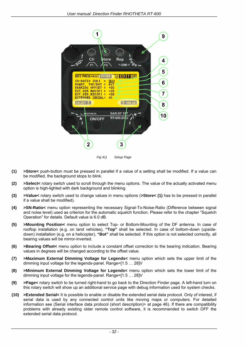
User manual Direction Finder RHOTHETA RT-600
- 32 -
Fig 41) Setup Page
(1) gtStorelt push-button must be pressed in parallel if a value of a setting shall be modified If a value can
be modified the background stops to blink
(2) gtSelectlt rotary switch used to scroll through the menu options The value of the actually activated menu option is high-lighted with dark background and blinking
(3) gtValuelt rotary switch used to change values in menu options (gtStorelt (1) has to be pressed in parallel if a value shall be modified)
(4) gtSN-Ratiolt menu option representing the necessary Signal-To-Noise-Ratio (Difference between signal and noise level) used as criterion for the automatic squelch function Please refer to the chapter ldquoSquelch Operationrdquo for details Default value is 60 dB
(5) gtMounting Positionlt menu option to select Top- or Bottom-Mounting of the DF antenna In case of rooftop installation (eg on land vehicles) ldquoToprdquo shall be selected In case of bottom-down (upside-down) installation (eg on a helicopter) ldquoBotrdquo shall be selected If this option is not selected correctly all bearing values will be mirror-inverted
(6) gtBearing Offsetlt menu option to include a constant offset correction to the bearing indication Bearing values in degrees will be changed according to the offset value
(7) gtMaximum External Dimming Voltage for Legendslt menu option which sets the upper limit of the dimming input voltage for the legends-panel Range=[15 hellip 28]V
(8) gtMinimum External Dimming Voltage for Legendslt menu option which sets the lower limit of the dimming input voltage for the legends-panel Range=[15 hellip 28]V
(9) gtPagelt rotary switch to be turned right-hand to go back to the Direction Finder page A left-hand turn on this rotary switch will show up an additional service page with debug information used for system checks
(10) gtExtended Seriallt It is possible to enable or disable the extended serial data protocol Only of interest if serial data is used by any connected control units like moving maps or computers For detailed information see (Serial interface data protocol (short description)gt at page 46) If there are compatibility problems with already existing older remote control software it is recommended to switch OFF the extended serial data protocol
User manual Direction Finder RHOTHETA RT-600
- 33 -
3 Error messages If an internal error of the device is recognized a corresponding flashing error message will be shown in the DF pages
Fig 42) Error Messages
(1) Error message including error code (in brackets)
(2) Short description of the indicated error
In case of coincidence of various errors the error with the highest priority will be displayed
Error message Error location Reason
Error (12) VOLTDU
Main voltage supply Main Voltage input too low ( 100 V)
Error (11) NO AU
Connection antenna display or Antenna Unit
No serial data (RS485) from Antenna Unit No or damaged connection between antenna and display or damaged antenna unit
Error (10) BAD AU
Connection antenna display
Incompatibility or bad data connection between display and antenna
Error (9) BAD RU
Remote Unit Incompatibility or bad data connection between display and external serial Remote Unit or PC
Error (8) VOLTAU
Antenna Unit Voltage supply at Antenna Unit too low ( 90 V) Main voltage supply too low or considerable drop of voltage between display and antenna
Error (7) BAD DCU
Connection Display Antenna
Incompatibility or bad data connection between antenna and display
Error (6) NO DCU
Connection Display Antenna
No serial data from Display Control Unit to Antenna Unit
Error (5) PLL ERR
antenna Error in synthesizer-oscillator of receiver in Antenna Unit
Error (4) FRQ+OFS
received transmitter Received frequency too high (more than 6 KHz error of transmitter)
Error (3) FRQ-OFS
received transmitter received frequency too low (more than 6 KHZ error of transmitter)
Error (2) DECODE
radio distance transmitter DF
Data Bits of decoded signal (COSPAS-SARSAT or LoJack) defective
Error (1) DATARNG
Incompatibility of data DCU AU
Protocol data bytes out of valid range
Error (0) NO REC
Antenna Unit receiver
Receiver board defective
User manual Direction Finder RHOTHETA RT-600
- 34 -
4 Installation
41 Antenna unit A convenient position of the monopole bearing antenna is crucial for good bearing results The antenna needs an effective ground connection to the body of the aircraft or to the roof of the vehicle If there is no metallic mounting surface available a metallic sheet or similar (net) with connection to ground has to be applied first between vehicle-body and antenna In this hatched area the antenna touches the body ofthe vehicleaircraft In order to obtain a good groundconnection the surface of the body should be bared(Measuring unit [mm])
8 x holes for mounting the antenna unit to the
vehicle aircraft
Fig 43) Antenna Mounting Drawing
User manual Direction Finder RHOTHETA RT-600
- 35 -
411 Influence of antenna location and environment on the bearing accuracy
Recommendations concerning the practical antenna unit location on helicopters and airplanes
The bearing accuracy of the direction finder antenna unit is severely influenced (comparable to an airspeed sensor) by the environment For comparison a perfect high quality speed sensor will not indicate the true airspeed if this sensor is interfered by strong turbulences The direction finder antenna unit acts as a sensor for electromagnetic waves In the near field of this antenna unit any conductive (eg metallic) obstacle will influence the incoming wave field and create reflections which decrease the bearing accuracy These are general physical limitations concerning all types of direction finder systems To achieve the best bearing results it should be considered that the antenna unit is installed as far away as possible from any other vertically polarized conductive structure If possible there should be no reflectors within an area of 2-3 feet around the antenna unit In this worst case example the direction finder will not work properly
Fig 44) Antenna Installed in a Bad Location
In this example the antenna unit is located too close to the cable cutter of the helicopter This cutter will produce strong reflections especially as the length is equal to Lambda4 within the VHF airband
User manual Direction Finder RHOTHETA RT-600
- 36 -
Examples of properly installed direction finder antenna units
Fig 45) Antenna Installed in Good Locations
User manual Direction Finder RHOTHETA RT-600
- 37 -
42 Display and Control Unit
The display control unit may be mounted into a front panel by the means of this mounting drawing
Fig 46) DCU Mounting Drawing
(all dimensions in [mm]) To install or uninstall the display control unit perform the following steps (1) Remove the cover caps of the four rotary switches
(2) Loose the screws visible below the position of the cover caps
(3) Remove the plastic button from the axis of the four rotary switches
(4) Mount dismount the display control unit
(5) Re-install the plastic buttons on the axis of the four rotary switches
(6) Fix the screws so that the plastic buttons are fixed on the axis
(7) Re-install the cover caps on the four rotary switches
User manual Direction Finder RHOTHETA RT-600
- 38 -
43 System Interconnect Wiring Diagram (Also refer to chapter ldquoTechnical Datardquo for details)
Fig 47) System Interconnect Wiring Diagram
6-pol Amphenol plug femalePTG06SE10-6S(SQ)
max length of cable 20 m 9-pol Sub-D plug (femalemale)
User manual Direction Finder RHOTHETA RT-600
- 39 -
5 Technical Data
51 Electric features
Method of bearing Doppler-principle (3 kHz rotational frequency right left rotation)
Bearing accuracy1 plusmn 5deg RMS
Internal resolution 1deg
Bearing Sensitivity VHF AirEmergency le 25 μVm (typical)
VHF Marine le 25 μVm (typical)
UHF Emergency and ETS le 4 μVm (typical)
COSPAS-SARSAT le 4 μVm (typical)
LoJack Decoding (50 Message Error Rate) and bearing le 5 μVm (typical)
Frequency stability plusmn 20 ppm (Δff = plusmn210-6)
Reception frequencies
SAR version (Standard)
Frequency Options
VHF Emergency Band 118000 to 124000 MHz (833 kHz steps AM)
VHF Marine Band 154000 to 163000 MHz ( 500 kHz steps FM) (channel 16 selectable via channel no)
UHF Emergency Band 240000 to 246000 MHz (2500 kHz steps AM)
UHF FM Band 406100 to 410000 MHz ( 500 kHz steps FM)
COSPAS-SARSAT 400000 to 406092 MHz Including 406022 to 406076 MHz (Channel A S)
F1 VHF Air Band 118000 to 136992 MHz
F2 extended VHF Marine Band 137000 to 224995 MHz
F3 extended UHF Air Band 225000 to 399975 MHz
F4 additional UHF FM Band 406100 to 470000 MHz
Reception frequencies
LAW Enforcement version
Frequency Options
VHF Emergency Band 118000 to 124000 MHz (833 kHz steps AM)
VHF Marine Band 154000 to 163000 MHz (500 kHz steps FM) (channel 16 selectable via channel no)
LoJack 164000 to 174000 MHz (125 kHz steps FM)
ETS 216000 to 220000 MHz (10125 kHz AM)
COSPAS-SARSAT 400000 to 406092 MHz Including 406022 to 406076 MHz (Channel A S)
F1VHF Air Band 118000 to 136992 MHz
F2 extended VHF Marine Band 137000 to 163000 MHz
COSPAS-SARSAT fast scan mode
Full automatic detection of any active COSPAS-SARSAT channel A to S within 400 ms
COSPAS-SARSAT decoding
Reception and decoding of COSPAS-SARSAT data signal (112 or 144 bit) specified according to COSPAS-SARSAT
LoJack decoding Selectable LoJack ID display and selective active filtering
Special scanning modes
complete maritime ship band scanning within 3 s (channel 01 hellip 88 also frequencies between 2 channels are included)
1With undisturbed wave field and sufficient field strength Measuring by changing the angle of incidence with the antenna rotating on a revolving table in order to eliminate environmental influences on the results No modulation
User manual Direction Finder RHOTHETA RT-600
- 40 -
Bearable modulation A3E F3E A3X (ELT-modulation) F1D G2D COSPAS-SARSAT Bearing largely independent of modulation
Polarization Vertical
Polarization error 5deg at 60deg field vector rotation
Garbling cone Ca 30deg to the vertical
Time of response2 50 ms (with sufficient reception field strength)
LC-graphic display 128 x 64 pixels supertwist transflective extended range of temperature dark-blue display on yellow-green background background light Freely adjustable (exponential) dimming of brightness
NVG cockpit design Fully compatible NVIS Green B display Control Unit optional
Operating voltage 275 V nominal 12 V to 35 V DC
Current consumption LCD-background light Off max 500 mA (12 V DC) max 250 mA (24 V DC)
LCD-background light 100 max 750 mA (12 V DC) max 350 mA (24 V DC)
LCD-background light 100 max 900 mA (12 V DC) with NVG Option max 400 mA (24 V DC)
Audio out For external speaker approx 2 W (4 Ω)
Serial data interface Serial interface RS-232 (9600 baud 8 data bits 1 stop bit no parity)
2Very weak signals can considerably increase the time of response
User manual Direction Finder RHOTHETA RT-600
- 41 -
52 Interface External connections (optional at Sub-D 9-pol Male connector)
Dimming
Pin 8
external voltage input for variable dimming of legends
(optional)
Analog input signal for variable control of the legends illumination Input voltage range is freely adjustable in the range of 15 hellip 28 V in the setup menu Refer to chapter ldquoSetup Pagerdquo Default setting 8 hellip28 V (8 V = Off 28 V = max dimming for legends)
Input Impedance gt 50 k
Pin 6 night status line for LCD
dimming (optional)
Low-active (as example switch to ground) At input voltage lt 25 VDC the LCD dimming operates in nightNVG mode Maximum brightness ca 4 of daydefault mode brightness
Input Impedance gt 50 k
Pin 4 NVG status line for LCD
dimming (optional)
Low-active (as example switch to ground) At input voltage lt 25 VDC the LCD dimming operates in nightNVG mode Maximum brightness ca 4 of daydefault mode brightness
Input Impedance gt 50 k
AudioLF
Pin 7 Audio output signal
AC coupled voltage source with very low inner resistance Maximum output voltage ca 8 VPP = 283V RMS at maximum Volume Maximum output power ca 2 W with 4 speaker
If a headphone is connected ([32hellip600] 100mW) we recommend using a resistor (18 025 W) between audio output and headphone to prevent damage of the headphone
Serial interface RS232 (9600 baud 8 data bits 1 stop bit no parity)
Pin 3 TXD Serial output (ca plusmn10 V)
Pin 2 RXD Serial input (ca plusmn10 V)
User manual Direction Finder RHOTHETA RT-600
- 42 -
53 Mechanical features
Temperature range
Display Control Unit permissible operating temperature3 -20 degC +60 degC permissible storage temperature -30 degC +80 degC
Antenna Unit permissible operating temperature3 -40 degC +60 degC permissible storage temperature -55 degC +80 degC
Protective system Antenna Unit IP 67
Weights Display Control Unit 250 g Antenna Unit 2000 g
Dimensions Display Control Unit 82 mm x 82 mm x 43 mm (width x height x depth) Antenna Unit 270 mm x 185 mm
Fig 48) DCU Mechanical Drawing (all dimensions in [mm])
3 For temperatures lower than ndash10deg C a warm-up period of 15 min should be allowed
User manual Direction Finder RHOTHETA RT-600
- 43 -
Fig 49) AU Mechanical Drawing (all dimensions in [mm])
User manual Direction Finder RHOTHETA RT-600
- 44 -
6 Appendix
61 Frequency Ranges
User manual Direction Finder RHOTHETA RT-600
- 45 -
62 Frequencies of channels on maritime band (only for standard [A] version) Frequency-range of the RT-600 in the maritime band 156000 MHz 162025 MHz
Channel No frequency (ship - station) Frequency (coast - station)
1 156050 MHz 160650 MHz 2 156100 MHz 160700 MHz 3 156150 MHz 160750 MHz 4 156200 MHz 160800 MHz 5 156250 MHz 160850 MHz 6 156300 MHz 160900 MHz 7 156350 MHz 160950 MHz 8 156400 MHz 9 156450 MHz
10 156500 MHz 11 156550 MHz 12 156600 MHz 13 156650 MHz 14 156700 MHz 15 156750 MHz 16 156800 MHz 17 156850 MHz 18 156900 MHz 161500 MHz 19 156950 MHz 161550 MHz 20 157000 MHz 161600 MHz 21 157050 MHz 161650 MHz 22 157100 MHz 161700 MHz 23 157150 MHz 161750 MHz 24 157200 MHz 161800 MHz 25 157250 MHz 161850 MHz 26 157300 MHz 161900 MHz 27 157350 MHz 161950 MHz 28 157400 MHz 162000 MHz 60 156025 MHz 160625 MHz 61 156075 MHz 160675 MHz 62 156125 MHz 160725 MHz 63 156175 MHz 160775 MHz 64 156225 MHz 160825 MHz 65 156275 MHz 160875 MHz 66 156325 MHz 160925 MHz 67 156375 MHz 68 156425 MHz 69 156475 MHz 70 156525 MHz 71 156575 MHz 72 156625 MHz 73 156675 MHz 74 156725 MHz 75 156775 MHz 76 156825 MHz 77 156875 MHz 78 156925 MHz 161525 MHz 79 156975 MHz 161575 MHz 80 157025 MHz 161625 MHz 81 157075 MHz 161675 MHz 82 157125 MHz 161725 MHz 83 157175 MHz 161775 MHz 84 157225 MHz 161825 MHz 85 157275 MHz 161875 MHz 86 157325 MHz 161925 MHz 87 157375 MHz 161975 MHz 88 157425 MHz 162025 MHz
User manual Direction Finder RHOTHETA RT-600
- 46 -
63 Serial interface data protocol (short description)
631 General
Interface parameters RS232 9600 Baud 8 databits 1 stopbit no parity LSB sent first Timing of serial data For accurate use of the serial data (even for the optional serial input commands) the correct timing is mandatory The DCU (Display Control Unit) sends out via the RS-232 Pins (see 43 System Interconnect Wiring Diagram page 38) cyclic and autonomous every approx 250300 ms a binary data stream which contains all relevant DF-bearing information The output data contains one or two blocks of binary data (see next picture with accordingly description) The optional serial input is only used if changes (as example frequency change) are done by additional remote control units
Fig 50) Timing of serial data
Serial standard output
This output data is always available and contains all relevant DF-bearing data For detailed content see page 47
Optional extended serial output
This data contains some additional information like as example CospasSarsat or LoJack decoding and ID data For detailed content see page 50 The data is only available with DCU Software [Rev ge 320] and if this optional data block is configured as ON = enabled (see Setup Edit Page point (10) )
Even to avoid compatibility problems with already existing older remote control software it is possible to disable switch off this additional data block (see Setup Edit Page point (10) )
Optional serial input
Only used for optional commands to control DCU parameters If as example the direction finder frequency is changed remotely there is send to the DCU one time this data block with the new frequency For detailed content see page 52
User manual Direction Finder RHOTHETA RT-600
- 47 -
632 Serial standard output (protocol description)
Specification serial standard output
The binary data stream with a length of 39 bytes starts with a header byte (value = hex 0xA0 as ID for DF Mode) The next bytes contain different values for status bearing information and also service The last byte is used for data stream checksum control Remark This is a binary data protocol So every byte value from 0dec hellip 255dec (0x00 hellip 0xFF) is possible Because of this it is not allowed to realize a start byte detection by the content (0xA0) The idle line detection is recommended for detection the end of message Register of databytes (for details see next page)
byte no
[0] Header = 0xA0 Id for DF Mode
[1] Number = 39 = bytes in the complete message (including header and checksumbyte)
[2] Status (1) HSB [x|x|x|x|x|x|x|x] LSB | | | | | | | --gt (0) Receiving | | | | | | ----gt (1) Squelch controlled by AU (X) | | | | | ------gt (2) Permission RL Calibration | | | | --------gt (3) Line Night | | | ----------gt (4) Line NVG | | ------------gt (5) Dimming External | --------------gt (6) Autosquelch Active ----------------gt (7) 0=Standard Version 1=LE Version
[3] Status (2) HSB [x|x|x|x|x|x|x|x] LSB | ----------------gt (7) 0=Standard 1=extended serial dataprotocol = ONactive
[45] Error (Bits[120])
[6] Actual DCU Page
[7] Volume [0hellip100]
[811] Frequency [Hz]
[12] Active Band
[13] Actual Squelchlevel [0hellip60]
[14] Audio-Line amp_NF_Test Output
[15] (Not used)
[1617] Voltage_DCU ([0hellip335]=[0 hellip 335]V
[1819] Voltage_AU ([0hellip255]=[0 hellip 255]V
[20] Temperature_AU [-68hellip+127]degC
[21] Frequency Offset [-99hellip+99]
[2225] ServiceTest values (mode dependent test values for service only)
26 (Not used reserved)
[27] Level [0hellip100]
[2829] Bearing Averaged [0hellip359]deg relative
[3031] Bearing Live_Min [0hellip359]deg relative
[3233] Bearing Live_Max [0hellip359]deg relative
[34] Test Value PS-RAM Right Rotation[0hellip178] (for service only)
[35] Test Value PS-RAM Left Rotation [0hellip178] (for service only)
[3637] (Not used reserved)
[38] Checksum is the 2rsquos complement of the modulo-256 sum of all bytes without checksum-byte [0n-1]
User manual Direction Finder RHOTHETA RT-600
- 48 -
Detailed Description of important values for practical use
Status byte [2] Receiving Bit 0 of this value (LSB) indicates signal receiving Bit 0 = 0 then no signal is received and so on no bearing is available Bit 0 = 1 then bearing is possible Bit 1 if(1) then Squelch is controlled by AU (active at modes CospasSarsat Decode CospasSarsat Scanning LoJack with Filter=ID only)
Error bytes [4hellip5] 16 bit value each set bit corresponds to the error no (Refer to the chapter Error messages) Example - 0x0000 No error - 0x0800 Bit No 11 Set ( = No AU Error)
Actual DCU Page byte [6] indicates actual operating mode of DCU 0 = Standard bearing page 1 = Frequency memory page 2 = CospasSarsat decoding page 3 = LoJack decoding page (ID edit)
Frequency bytes [8hellip11] 32 bit value actual adjusted frequency [Hz] Example - 0x073DF160 1215000000 121500 MHz
Active Band Standard Version [A] 0=VHF Airband 1=VHF Marineband sea 2=VHF Marineband coast 3=UHV Airband 4=CospasSarsat LE Version [L] 0=VHF Airband 1=LoJack 2=Lifesaver 3=ETS 4=CospasSarsat
Actual Squelchlevel byte [13] Range [0hellip60] without signal the actual squelchlevel should always be adjusted a little bit over the noise level (Refer to the chapter Squelch operation)
Level byte [27] Range [099] actual receiving level (without signal this value is equal to the noise level) If a signal is received then this value corresponds to the signal strength of this signal
Relative Bearing averaged byte [2829] 16 bit value Range [0hellip359 0xFFFF] if the value = 0xFFFF then no valid bearing is available otherwise this value contains the actual averaged bearing information in Deg [0deg359deg] Example - 0X0114 276deg bearing (= left side oriented to heading)
Bearing Live MinMax byte[3031] amp [3233] - 16 bit values Range [0hellip359 0xFFFF] Only for signal quality or additional information ndash NOT recommended for bearing indication The relative live bearing field contains the maxmin bearing in degrees without averaging The relative live bearing reacts faster than the normal relative bearing but it has not the precision of the averaged bearing The MinMax Bearing Values are calculated within a time period of approx 250 ms If they are very close together (for example ldquo124rdquo and ldquo128rdquo degrees) then the signal quality is quite good A wide span of the minmax values (for example ldquo97rdquo and ldquo162rdquo) shows very noisy but nevertheless bearable signal quality
User manual Direction Finder RHOTHETA RT-600
- 49 -
633 DCU Info output (protocol description)
Specification DCU Info output
Remark This protocol is only available while the SetupEdit page is activated at the DCU
byte no
[0] Header = 0xAF Id for DCU Info Mode
[1] Number = 39 = bytes in the complete message (including header and checksumbyte)
[2]
(see standard output) [3]
[45]
[621] Info String of 15 byteschars the string contains Information about Unit Variant Software Version and Serial No
Example Byte [318] =
|--AU ID---||Var-||---Software Version---| |-------------- Serial No---------------| [0x44][0x55][0x41][0x33][0x2E][0x33][0x30][0x3A][0x20][0x20][0x30][0x31][0x32][0x33][0x34][0x00] rsquoDrsquo rsquoUrsquo rsquoArsquo rsquo3rsquo rsquorsquo rsquo3rsquo rsquo0rsquo rsquorsquo rsquo rsquo rsquo rsquo rsquo0rsquo rsquo1rsquo rsquo2rsquo rsquo3rsquo rsquo4rsquo rsquoENDrsquo | | | | __________________ | | ________________________ | n n n | | n n n n n | (Software Version) | | (Serial No) | gt rsquoArsquo = Standard Variant gt rsquoLrsquo = Law Enforcement Variant
User manual Direction Finder RHOTHETA RT-600
- 50 -
634 Optional extended serial output (protocol description)
The data content depends on the actual mode of the direction finder To get special data the direction finder has first to be switched to the equivalent mode
COSPAS-SARSAT Decoding data
This data is only available and valid if Display Control Unit with actual software Rev ge 320 (see Power-On procedure page 10) Configuration of Extended serial = ON (see Setup Edit Page point (10) ) Direction Finder COSPAS-SARSAT decoding mode is activated by selecting the corresponding page
(see COSPAS-SARSAT Decode Window page 20 and page 21) and so on Header (byte 0 of data) = 0x91
A valid COSPAS-SARSAT decoding data protocol is always marked by the first data byte (header = 0x91) Always after receiving and decoding of a valid COSPAS-SARSAT pulse the complete data protocol with 33 bytes is send out one time
Byte No
[0] Header = 0x91 (Identification for CPSarsat decoding mode)
[1] Number of bytes - 7 if no decoded pulse is available - 33 if new pulse was received and is available
[2] Error
[3] Bit[0] - 0 =gt No new 406 MSG (decoded data) available - 1 =gt New valid 406 MSG available (Sync amp Frame Ok) Check Error Status for Bit-Errors
Bit[61] AutoSquelch Level valid range [060] ( decimal)
Bit[7] = 1 Squelch controlled by AU
[4] Signallevel of received signal valid range [099] ( decimal)
[5] Voltage of Antenna Unit Power Supply input valid range [80255] (decimal = 80 255 V DC)
[6] Temperature inside Antenna Unit valid range [-50+100] (degC signed byte value)
The following databytes are only available if a correct CPSarsat puls gets received and decoded with correct checksum
[724] 18 x Databytes complete orginal CPSarsat 406 decoded message (144 bit)
Databyte Nr [ Byte 7 ] [ Byte 8 ] [Byte9 Byte24] 406 MSG Bit Nr [1 2 3 4 5 6 7 8] [9 10 11 12 13 14 15 16] [17 144]
[25] SN-Flag valid values 0x53=rsquoSrsquo 0x4E=rsquoNrsquo 0x2D=rsquo-rsquo if no GPS data available
GPS-Position Latitude
[26] Deg valid values [090] (decimal Deg) 0xFF if no GPS data available
[27] Min valid values [059] (decimal Deg) 0xFF if no GPS data available
[28] Sec valid values [059] (decimal Deg) 0xFF if no GPS data available
[29] WE-Flag valid values 0x57=rsquoWrsquo 0x45=rsquoErsquo 0x2D=rsquo-rsquo if no GPS data available
GPS-Position Longitude
[30] Deg valid values [0180] (decimal Deg) 0xFF if no GPS data available
[31] Min valid values [059] (decimal Deg) 0xFF if no GPS data available
[32] Sec valid values [059] (decimal Deg) 0xFF if no GPS data available
User manual Direction Finder RHOTHETA RT-600
- 51 -
LoJack ID data
This data is only available and valid if Display Control Unit with actual software Rev ge 320 (see Power-On procedure page 10) Direction Finder of variant [L] Law Enforcement Configuration of Extended serial = ON (see Setup Edit Page point (10) ) Direction Finder is working with active LoJack gtID Filterlt Header (byte 0 of data) = 0x93 or 0x94
Valid LoJack ID decoding data is always marked by the first data byte (header = 0x93 or 0x94)
Byte No
[0] Header = 0x93 LoJack ID editing sub-page is selected Filter = VLU all valid and received LoJack pulses are indicated = 0x94 Lojack Decode amp DF Mode with active Filter = ID
[1] Number of bytes in the complete data stream - decimal 26 = default value
[2] Nonrelevant
[3] Bit[0] Receiving OnOff - 0 =gt No Receiving no bearing - 1 =gt new LoJack pulse received
[412] Nonrelevant
[1317] Lojack ID
Replay Code 5 x ASCII Chars ldquoNo BIOZrdquo set
Example ASCII = ldquo000R1rdquo
18 Receiver Level Out Max [099]
19
LoJack Decoder Status [07] - 0 Off - 1 Wait for Preamble - 2 Preamble Ok - 3 FlagPattern Ok - 4 Data BitError gt 1 - 5 Data Ok (No VLU) - 6 VLU Ok - 7 ID Ok (Filter=IDONLY)
[2025] Nonrelevant
Remark Only if byte no [3] bit [0] gets ldquo1rdquo (Receiving On) then an active LoJack pulse is received and so on the corresponding LoJack ID valid otherwise the LoJack ID only shows the actual adjusted LoJack Filter ID of the direction finder
User manual Direction Finder RHOTHETA RT-600
- 52 -
635 Optional serial input (protocol description)
Specification serial input (optional)
The serial input is normally used for service and maintenance only Nevertheless it is possible via this interface to remote control the actual frequency and the squelchlevel of the DF system If a valid data stream is send to the DF then the actual frequency selection at the DCU is switched to Block2 AUX0 At this memory channel the new frequency is stored and used automatically (Refer to the chapter Frequency Selection Page) If the frequency is changed (by one valid data stream) no more serial input is necessary The actual frequency can be changed again at any time by manual operation at the DCU The timing of serial input (if used) is strictly fixed The optional serial input has to take place directly after a complete serial output (max 50 ms delay time) If a new changed frequency is commanded to the DCU via this serial input interface it can take up to 1 sec of time until this new frequency is ready for operationbearing It is strictly not recommended to use the frequency remote control for any scan mode The frequency control has to be used for static frequency change only Register of databytes
byte no
[0] Header 0xC0
[1] Number of bytes in the complete message (including header and checksumbyte)
[23] (not used for normal operation any byte values allowed)
[4] Volume [0100]
[58] Frequency [Hz] (frequency is rounded to the according grid automatically)
Valid Range for Standard Version Valid Range for LE Version
118000000 hellip 123000000 [Hz] 8333 kHz 118000000 hellip 123000000 [Hz] 8333 kHz
156050000 hellip 162025000 [Hz] 5000 kHz 164000000 hellip 174000000 [Hz] 8333 kHz
201000000 hellip 215995000 [Hz] 5000 kHz
240000000 hellip 246000000 [Hz] 8333 kHz 216000000 hellip 218995000 [Hz] 12500 kHz219000000 hellip 220000000 [Hz] 10000 kHz
400000000 hellip 410000000 [Hz] 8333 kHz 400000000 hellip 410000000 [Hz] 8333 kHz
[9] Squelchlevel Manual = [0hellip60] Autosql= [ -1] Warning use only for pulsed signals (as example CpSarsat LoJack)
[10] (not used for normal operation any byte values allowed)
[11] Internal Dimming [0100]
[12] Checksum is the 2rsquos complement of the modulo-256 sum of all bytes without checksum-byte [0n-1]
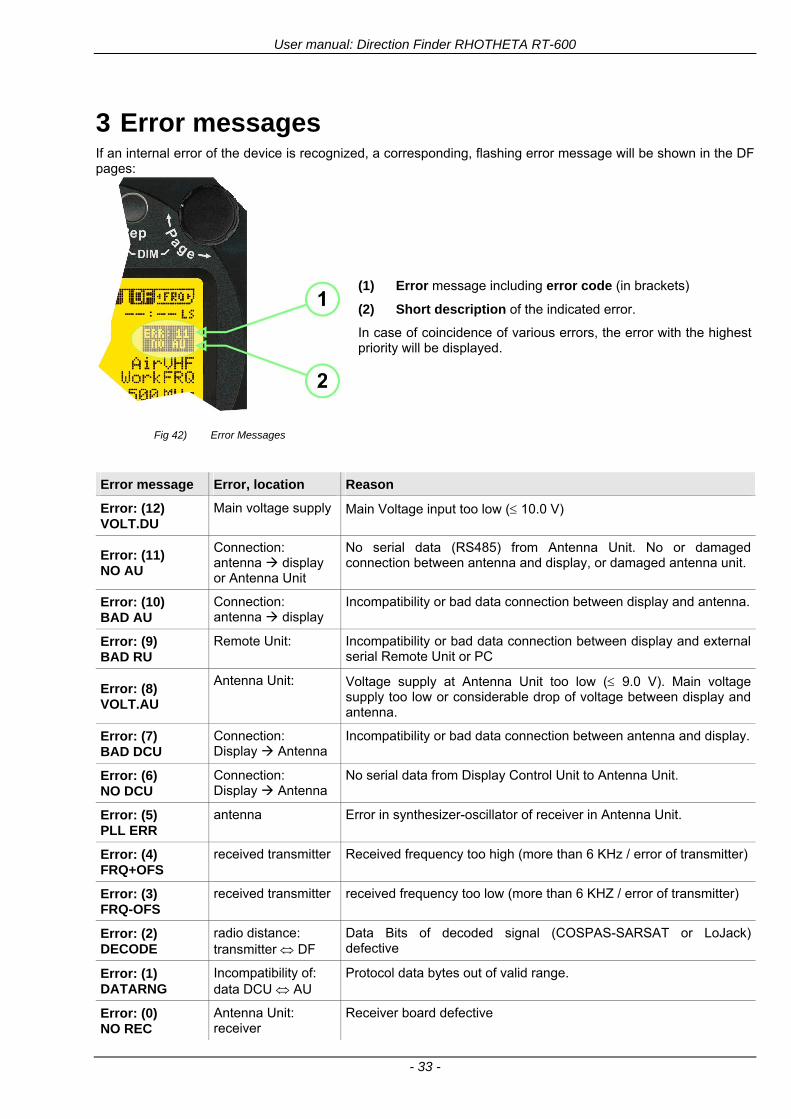
User manual Direction Finder RHOTHETA RT-600
- 33 -
3 Error messages If an internal error of the device is recognized a corresponding flashing error message will be shown in the DF pages
Fig 42) Error Messages
(1) Error message including error code (in brackets)
(2) Short description of the indicated error
In case of coincidence of various errors the error with the highest priority will be displayed
Error message Error location Reason
Error (12) VOLTDU
Main voltage supply Main Voltage input too low ( 100 V)
Error (11) NO AU
Connection antenna display or Antenna Unit
No serial data (RS485) from Antenna Unit No or damaged connection between antenna and display or damaged antenna unit
Error (10) BAD AU
Connection antenna display
Incompatibility or bad data connection between display and antenna
Error (9) BAD RU
Remote Unit Incompatibility or bad data connection between display and external serial Remote Unit or PC
Error (8) VOLTAU
Antenna Unit Voltage supply at Antenna Unit too low ( 90 V) Main voltage supply too low or considerable drop of voltage between display and antenna
Error (7) BAD DCU
Connection Display Antenna
Incompatibility or bad data connection between antenna and display
Error (6) NO DCU
Connection Display Antenna
No serial data from Display Control Unit to Antenna Unit
Error (5) PLL ERR
antenna Error in synthesizer-oscillator of receiver in Antenna Unit
Error (4) FRQ+OFS
received transmitter Received frequency too high (more than 6 KHz error of transmitter)
Error (3) FRQ-OFS
received transmitter received frequency too low (more than 6 KHZ error of transmitter)
Error (2) DECODE
radio distance transmitter DF
Data Bits of decoded signal (COSPAS-SARSAT or LoJack) defective
Error (1) DATARNG
Incompatibility of data DCU AU
Protocol data bytes out of valid range
Error (0) NO REC
Antenna Unit receiver
Receiver board defective
User manual Direction Finder RHOTHETA RT-600
- 34 -
4 Installation
41 Antenna unit A convenient position of the monopole bearing antenna is crucial for good bearing results The antenna needs an effective ground connection to the body of the aircraft or to the roof of the vehicle If there is no metallic mounting surface available a metallic sheet or similar (net) with connection to ground has to be applied first between vehicle-body and antenna In this hatched area the antenna touches the body ofthe vehicleaircraft In order to obtain a good groundconnection the surface of the body should be bared(Measuring unit [mm])
8 x holes for mounting the antenna unit to the
vehicle aircraft
Fig 43) Antenna Mounting Drawing
User manual Direction Finder RHOTHETA RT-600
- 35 -
411 Influence of antenna location and environment on the bearing accuracy
Recommendations concerning the practical antenna unit location on helicopters and airplanes
The bearing accuracy of the direction finder antenna unit is severely influenced (comparable to an airspeed sensor) by the environment For comparison a perfect high quality speed sensor will not indicate the true airspeed if this sensor is interfered by strong turbulences The direction finder antenna unit acts as a sensor for electromagnetic waves In the near field of this antenna unit any conductive (eg metallic) obstacle will influence the incoming wave field and create reflections which decrease the bearing accuracy These are general physical limitations concerning all types of direction finder systems To achieve the best bearing results it should be considered that the antenna unit is installed as far away as possible from any other vertically polarized conductive structure If possible there should be no reflectors within an area of 2-3 feet around the antenna unit In this worst case example the direction finder will not work properly
Fig 44) Antenna Installed in a Bad Location
In this example the antenna unit is located too close to the cable cutter of the helicopter This cutter will produce strong reflections especially as the length is equal to Lambda4 within the VHF airband
User manual Direction Finder RHOTHETA RT-600
- 36 -
Examples of properly installed direction finder antenna units
Fig 45) Antenna Installed in Good Locations
User manual Direction Finder RHOTHETA RT-600
- 37 -
42 Display and Control Unit
The display control unit may be mounted into a front panel by the means of this mounting drawing
Fig 46) DCU Mounting Drawing
(all dimensions in [mm]) To install or uninstall the display control unit perform the following steps (1) Remove the cover caps of the four rotary switches
(2) Loose the screws visible below the position of the cover caps
(3) Remove the plastic button from the axis of the four rotary switches
(4) Mount dismount the display control unit
(5) Re-install the plastic buttons on the axis of the four rotary switches
(6) Fix the screws so that the plastic buttons are fixed on the axis
(7) Re-install the cover caps on the four rotary switches
User manual Direction Finder RHOTHETA RT-600
- 38 -
43 System Interconnect Wiring Diagram (Also refer to chapter ldquoTechnical Datardquo for details)
Fig 47) System Interconnect Wiring Diagram
6-pol Amphenol plug femalePTG06SE10-6S(SQ)
max length of cable 20 m 9-pol Sub-D plug (femalemale)
User manual Direction Finder RHOTHETA RT-600
- 39 -
5 Technical Data
51 Electric features
Method of bearing Doppler-principle (3 kHz rotational frequency right left rotation)
Bearing accuracy1 plusmn 5deg RMS
Internal resolution 1deg
Bearing Sensitivity VHF AirEmergency le 25 μVm (typical)
VHF Marine le 25 μVm (typical)
UHF Emergency and ETS le 4 μVm (typical)
COSPAS-SARSAT le 4 μVm (typical)
LoJack Decoding (50 Message Error Rate) and bearing le 5 μVm (typical)
Frequency stability plusmn 20 ppm (Δff = plusmn210-6)
Reception frequencies
SAR version (Standard)
Frequency Options
VHF Emergency Band 118000 to 124000 MHz (833 kHz steps AM)
VHF Marine Band 154000 to 163000 MHz ( 500 kHz steps FM) (channel 16 selectable via channel no)
UHF Emergency Band 240000 to 246000 MHz (2500 kHz steps AM)
UHF FM Band 406100 to 410000 MHz ( 500 kHz steps FM)
COSPAS-SARSAT 400000 to 406092 MHz Including 406022 to 406076 MHz (Channel A S)
F1 VHF Air Band 118000 to 136992 MHz
F2 extended VHF Marine Band 137000 to 224995 MHz
F3 extended UHF Air Band 225000 to 399975 MHz
F4 additional UHF FM Band 406100 to 470000 MHz
Reception frequencies
LAW Enforcement version
Frequency Options
VHF Emergency Band 118000 to 124000 MHz (833 kHz steps AM)
VHF Marine Band 154000 to 163000 MHz (500 kHz steps FM) (channel 16 selectable via channel no)
LoJack 164000 to 174000 MHz (125 kHz steps FM)
ETS 216000 to 220000 MHz (10125 kHz AM)
COSPAS-SARSAT 400000 to 406092 MHz Including 406022 to 406076 MHz (Channel A S)
F1VHF Air Band 118000 to 136992 MHz
F2 extended VHF Marine Band 137000 to 163000 MHz
COSPAS-SARSAT fast scan mode
Full automatic detection of any active COSPAS-SARSAT channel A to S within 400 ms
COSPAS-SARSAT decoding
Reception and decoding of COSPAS-SARSAT data signal (112 or 144 bit) specified according to COSPAS-SARSAT
LoJack decoding Selectable LoJack ID display and selective active filtering
Special scanning modes
complete maritime ship band scanning within 3 s (channel 01 hellip 88 also frequencies between 2 channels are included)
1With undisturbed wave field and sufficient field strength Measuring by changing the angle of incidence with the antenna rotating on a revolving table in order to eliminate environmental influences on the results No modulation
User manual Direction Finder RHOTHETA RT-600
- 40 -
Bearable modulation A3E F3E A3X (ELT-modulation) F1D G2D COSPAS-SARSAT Bearing largely independent of modulation
Polarization Vertical
Polarization error 5deg at 60deg field vector rotation
Garbling cone Ca 30deg to the vertical
Time of response2 50 ms (with sufficient reception field strength)
LC-graphic display 128 x 64 pixels supertwist transflective extended range of temperature dark-blue display on yellow-green background background light Freely adjustable (exponential) dimming of brightness
NVG cockpit design Fully compatible NVIS Green B display Control Unit optional
Operating voltage 275 V nominal 12 V to 35 V DC
Current consumption LCD-background light Off max 500 mA (12 V DC) max 250 mA (24 V DC)
LCD-background light 100 max 750 mA (12 V DC) max 350 mA (24 V DC)
LCD-background light 100 max 900 mA (12 V DC) with NVG Option max 400 mA (24 V DC)
Audio out For external speaker approx 2 W (4 Ω)
Serial data interface Serial interface RS-232 (9600 baud 8 data bits 1 stop bit no parity)
2Very weak signals can considerably increase the time of response
User manual Direction Finder RHOTHETA RT-600
- 41 -
52 Interface External connections (optional at Sub-D 9-pol Male connector)
Dimming
Pin 8
external voltage input for variable dimming of legends
(optional)
Analog input signal for variable control of the legends illumination Input voltage range is freely adjustable in the range of 15 hellip 28 V in the setup menu Refer to chapter ldquoSetup Pagerdquo Default setting 8 hellip28 V (8 V = Off 28 V = max dimming for legends)
Input Impedance gt 50 k
Pin 6 night status line for LCD
dimming (optional)
Low-active (as example switch to ground) At input voltage lt 25 VDC the LCD dimming operates in nightNVG mode Maximum brightness ca 4 of daydefault mode brightness
Input Impedance gt 50 k
Pin 4 NVG status line for LCD
dimming (optional)
Low-active (as example switch to ground) At input voltage lt 25 VDC the LCD dimming operates in nightNVG mode Maximum brightness ca 4 of daydefault mode brightness
Input Impedance gt 50 k
AudioLF
Pin 7 Audio output signal
AC coupled voltage source with very low inner resistance Maximum output voltage ca 8 VPP = 283V RMS at maximum Volume Maximum output power ca 2 W with 4 speaker
If a headphone is connected ([32hellip600] 100mW) we recommend using a resistor (18 025 W) between audio output and headphone to prevent damage of the headphone
Serial interface RS232 (9600 baud 8 data bits 1 stop bit no parity)
Pin 3 TXD Serial output (ca plusmn10 V)
Pin 2 RXD Serial input (ca plusmn10 V)
User manual Direction Finder RHOTHETA RT-600
- 42 -
53 Mechanical features
Temperature range
Display Control Unit permissible operating temperature3 -20 degC +60 degC permissible storage temperature -30 degC +80 degC
Antenna Unit permissible operating temperature3 -40 degC +60 degC permissible storage temperature -55 degC +80 degC
Protective system Antenna Unit IP 67
Weights Display Control Unit 250 g Antenna Unit 2000 g
Dimensions Display Control Unit 82 mm x 82 mm x 43 mm (width x height x depth) Antenna Unit 270 mm x 185 mm
Fig 48) DCU Mechanical Drawing (all dimensions in [mm])
3 For temperatures lower than ndash10deg C a warm-up period of 15 min should be allowed
User manual Direction Finder RHOTHETA RT-600
- 43 -
Fig 49) AU Mechanical Drawing (all dimensions in [mm])
User manual Direction Finder RHOTHETA RT-600
- 44 -
6 Appendix
61 Frequency Ranges
User manual Direction Finder RHOTHETA RT-600
- 45 -
62 Frequencies of channels on maritime band (only for standard [A] version) Frequency-range of the RT-600 in the maritime band 156000 MHz 162025 MHz
Channel No frequency (ship - station) Frequency (coast - station)
1 156050 MHz 160650 MHz 2 156100 MHz 160700 MHz 3 156150 MHz 160750 MHz 4 156200 MHz 160800 MHz 5 156250 MHz 160850 MHz 6 156300 MHz 160900 MHz 7 156350 MHz 160950 MHz 8 156400 MHz 9 156450 MHz
10 156500 MHz 11 156550 MHz 12 156600 MHz 13 156650 MHz 14 156700 MHz 15 156750 MHz 16 156800 MHz 17 156850 MHz 18 156900 MHz 161500 MHz 19 156950 MHz 161550 MHz 20 157000 MHz 161600 MHz 21 157050 MHz 161650 MHz 22 157100 MHz 161700 MHz 23 157150 MHz 161750 MHz 24 157200 MHz 161800 MHz 25 157250 MHz 161850 MHz 26 157300 MHz 161900 MHz 27 157350 MHz 161950 MHz 28 157400 MHz 162000 MHz 60 156025 MHz 160625 MHz 61 156075 MHz 160675 MHz 62 156125 MHz 160725 MHz 63 156175 MHz 160775 MHz 64 156225 MHz 160825 MHz 65 156275 MHz 160875 MHz 66 156325 MHz 160925 MHz 67 156375 MHz 68 156425 MHz 69 156475 MHz 70 156525 MHz 71 156575 MHz 72 156625 MHz 73 156675 MHz 74 156725 MHz 75 156775 MHz 76 156825 MHz 77 156875 MHz 78 156925 MHz 161525 MHz 79 156975 MHz 161575 MHz 80 157025 MHz 161625 MHz 81 157075 MHz 161675 MHz 82 157125 MHz 161725 MHz 83 157175 MHz 161775 MHz 84 157225 MHz 161825 MHz 85 157275 MHz 161875 MHz 86 157325 MHz 161925 MHz 87 157375 MHz 161975 MHz 88 157425 MHz 162025 MHz
User manual Direction Finder RHOTHETA RT-600
- 46 -
63 Serial interface data protocol (short description)
631 General
Interface parameters RS232 9600 Baud 8 databits 1 stopbit no parity LSB sent first Timing of serial data For accurate use of the serial data (even for the optional serial input commands) the correct timing is mandatory The DCU (Display Control Unit) sends out via the RS-232 Pins (see 43 System Interconnect Wiring Diagram page 38) cyclic and autonomous every approx 250300 ms a binary data stream which contains all relevant DF-bearing information The output data contains one or two blocks of binary data (see next picture with accordingly description) The optional serial input is only used if changes (as example frequency change) are done by additional remote control units
Fig 50) Timing of serial data
Serial standard output
This output data is always available and contains all relevant DF-bearing data For detailed content see page 47
Optional extended serial output
This data contains some additional information like as example CospasSarsat or LoJack decoding and ID data For detailed content see page 50 The data is only available with DCU Software [Rev ge 320] and if this optional data block is configured as ON = enabled (see Setup Edit Page point (10) )
Even to avoid compatibility problems with already existing older remote control software it is possible to disable switch off this additional data block (see Setup Edit Page point (10) )
Optional serial input
Only used for optional commands to control DCU parameters If as example the direction finder frequency is changed remotely there is send to the DCU one time this data block with the new frequency For detailed content see page 52
User manual Direction Finder RHOTHETA RT-600
- 47 -
632 Serial standard output (protocol description)
Specification serial standard output
The binary data stream with a length of 39 bytes starts with a header byte (value = hex 0xA0 as ID for DF Mode) The next bytes contain different values for status bearing information and also service The last byte is used for data stream checksum control Remark This is a binary data protocol So every byte value from 0dec hellip 255dec (0x00 hellip 0xFF) is possible Because of this it is not allowed to realize a start byte detection by the content (0xA0) The idle line detection is recommended for detection the end of message Register of databytes (for details see next page)
byte no
[0] Header = 0xA0 Id for DF Mode
[1] Number = 39 = bytes in the complete message (including header and checksumbyte)
[2] Status (1) HSB [x|x|x|x|x|x|x|x] LSB | | | | | | | --gt (0) Receiving | | | | | | ----gt (1) Squelch controlled by AU (X) | | | | | ------gt (2) Permission RL Calibration | | | | --------gt (3) Line Night | | | ----------gt (4) Line NVG | | ------------gt (5) Dimming External | --------------gt (6) Autosquelch Active ----------------gt (7) 0=Standard Version 1=LE Version
[3] Status (2) HSB [x|x|x|x|x|x|x|x] LSB | ----------------gt (7) 0=Standard 1=extended serial dataprotocol = ONactive
[45] Error (Bits[120])
[6] Actual DCU Page
[7] Volume [0hellip100]
[811] Frequency [Hz]
[12] Active Band
[13] Actual Squelchlevel [0hellip60]
[14] Audio-Line amp_NF_Test Output
[15] (Not used)
[1617] Voltage_DCU ([0hellip335]=[0 hellip 335]V
[1819] Voltage_AU ([0hellip255]=[0 hellip 255]V
[20] Temperature_AU [-68hellip+127]degC
[21] Frequency Offset [-99hellip+99]
[2225] ServiceTest values (mode dependent test values for service only)
26 (Not used reserved)
[27] Level [0hellip100]
[2829] Bearing Averaged [0hellip359]deg relative
[3031] Bearing Live_Min [0hellip359]deg relative
[3233] Bearing Live_Max [0hellip359]deg relative
[34] Test Value PS-RAM Right Rotation[0hellip178] (for service only)
[35] Test Value PS-RAM Left Rotation [0hellip178] (for service only)
[3637] (Not used reserved)
[38] Checksum is the 2rsquos complement of the modulo-256 sum of all bytes without checksum-byte [0n-1]
User manual Direction Finder RHOTHETA RT-600
- 48 -
Detailed Description of important values for practical use
Status byte [2] Receiving Bit 0 of this value (LSB) indicates signal receiving Bit 0 = 0 then no signal is received and so on no bearing is available Bit 0 = 1 then bearing is possible Bit 1 if(1) then Squelch is controlled by AU (active at modes CospasSarsat Decode CospasSarsat Scanning LoJack with Filter=ID only)
Error bytes [4hellip5] 16 bit value each set bit corresponds to the error no (Refer to the chapter Error messages) Example - 0x0000 No error - 0x0800 Bit No 11 Set ( = No AU Error)
Actual DCU Page byte [6] indicates actual operating mode of DCU 0 = Standard bearing page 1 = Frequency memory page 2 = CospasSarsat decoding page 3 = LoJack decoding page (ID edit)
Frequency bytes [8hellip11] 32 bit value actual adjusted frequency [Hz] Example - 0x073DF160 1215000000 121500 MHz
Active Band Standard Version [A] 0=VHF Airband 1=VHF Marineband sea 2=VHF Marineband coast 3=UHV Airband 4=CospasSarsat LE Version [L] 0=VHF Airband 1=LoJack 2=Lifesaver 3=ETS 4=CospasSarsat
Actual Squelchlevel byte [13] Range [0hellip60] without signal the actual squelchlevel should always be adjusted a little bit over the noise level (Refer to the chapter Squelch operation)
Level byte [27] Range [099] actual receiving level (without signal this value is equal to the noise level) If a signal is received then this value corresponds to the signal strength of this signal
Relative Bearing averaged byte [2829] 16 bit value Range [0hellip359 0xFFFF] if the value = 0xFFFF then no valid bearing is available otherwise this value contains the actual averaged bearing information in Deg [0deg359deg] Example - 0X0114 276deg bearing (= left side oriented to heading)
Bearing Live MinMax byte[3031] amp [3233] - 16 bit values Range [0hellip359 0xFFFF] Only for signal quality or additional information ndash NOT recommended for bearing indication The relative live bearing field contains the maxmin bearing in degrees without averaging The relative live bearing reacts faster than the normal relative bearing but it has not the precision of the averaged bearing The MinMax Bearing Values are calculated within a time period of approx 250 ms If they are very close together (for example ldquo124rdquo and ldquo128rdquo degrees) then the signal quality is quite good A wide span of the minmax values (for example ldquo97rdquo and ldquo162rdquo) shows very noisy but nevertheless bearable signal quality
User manual Direction Finder RHOTHETA RT-600
- 49 -
633 DCU Info output (protocol description)
Specification DCU Info output
Remark This protocol is only available while the SetupEdit page is activated at the DCU
byte no
[0] Header = 0xAF Id for DCU Info Mode
[1] Number = 39 = bytes in the complete message (including header and checksumbyte)
[2]
(see standard output) [3]
[45]
[621] Info String of 15 byteschars the string contains Information about Unit Variant Software Version and Serial No
Example Byte [318] =
|--AU ID---||Var-||---Software Version---| |-------------- Serial No---------------| [0x44][0x55][0x41][0x33][0x2E][0x33][0x30][0x3A][0x20][0x20][0x30][0x31][0x32][0x33][0x34][0x00] rsquoDrsquo rsquoUrsquo rsquoArsquo rsquo3rsquo rsquorsquo rsquo3rsquo rsquo0rsquo rsquorsquo rsquo rsquo rsquo rsquo rsquo0rsquo rsquo1rsquo rsquo2rsquo rsquo3rsquo rsquo4rsquo rsquoENDrsquo | | | | __________________ | | ________________________ | n n n | | n n n n n | (Software Version) | | (Serial No) | gt rsquoArsquo = Standard Variant gt rsquoLrsquo = Law Enforcement Variant
User manual Direction Finder RHOTHETA RT-600
- 50 -
634 Optional extended serial output (protocol description)
The data content depends on the actual mode of the direction finder To get special data the direction finder has first to be switched to the equivalent mode
COSPAS-SARSAT Decoding data
This data is only available and valid if Display Control Unit with actual software Rev ge 320 (see Power-On procedure page 10) Configuration of Extended serial = ON (see Setup Edit Page point (10) ) Direction Finder COSPAS-SARSAT decoding mode is activated by selecting the corresponding page
(see COSPAS-SARSAT Decode Window page 20 and page 21) and so on Header (byte 0 of data) = 0x91
A valid COSPAS-SARSAT decoding data protocol is always marked by the first data byte (header = 0x91) Always after receiving and decoding of a valid COSPAS-SARSAT pulse the complete data protocol with 33 bytes is send out one time
Byte No
[0] Header = 0x91 (Identification for CPSarsat decoding mode)
[1] Number of bytes - 7 if no decoded pulse is available - 33 if new pulse was received and is available
[2] Error
[3] Bit[0] - 0 =gt No new 406 MSG (decoded data) available - 1 =gt New valid 406 MSG available (Sync amp Frame Ok) Check Error Status for Bit-Errors
Bit[61] AutoSquelch Level valid range [060] ( decimal)
Bit[7] = 1 Squelch controlled by AU
[4] Signallevel of received signal valid range [099] ( decimal)
[5] Voltage of Antenna Unit Power Supply input valid range [80255] (decimal = 80 255 V DC)
[6] Temperature inside Antenna Unit valid range [-50+100] (degC signed byte value)
The following databytes are only available if a correct CPSarsat puls gets received and decoded with correct checksum
[724] 18 x Databytes complete orginal CPSarsat 406 decoded message (144 bit)
Databyte Nr [ Byte 7 ] [ Byte 8 ] [Byte9 Byte24] 406 MSG Bit Nr [1 2 3 4 5 6 7 8] [9 10 11 12 13 14 15 16] [17 144]
[25] SN-Flag valid values 0x53=rsquoSrsquo 0x4E=rsquoNrsquo 0x2D=rsquo-rsquo if no GPS data available
GPS-Position Latitude
[26] Deg valid values [090] (decimal Deg) 0xFF if no GPS data available
[27] Min valid values [059] (decimal Deg) 0xFF if no GPS data available
[28] Sec valid values [059] (decimal Deg) 0xFF if no GPS data available
[29] WE-Flag valid values 0x57=rsquoWrsquo 0x45=rsquoErsquo 0x2D=rsquo-rsquo if no GPS data available
GPS-Position Longitude
[30] Deg valid values [0180] (decimal Deg) 0xFF if no GPS data available
[31] Min valid values [059] (decimal Deg) 0xFF if no GPS data available
[32] Sec valid values [059] (decimal Deg) 0xFF if no GPS data available
User manual Direction Finder RHOTHETA RT-600
- 51 -
LoJack ID data
This data is only available and valid if Display Control Unit with actual software Rev ge 320 (see Power-On procedure page 10) Direction Finder of variant [L] Law Enforcement Configuration of Extended serial = ON (see Setup Edit Page point (10) ) Direction Finder is working with active LoJack gtID Filterlt Header (byte 0 of data) = 0x93 or 0x94
Valid LoJack ID decoding data is always marked by the first data byte (header = 0x93 or 0x94)
Byte No
[0] Header = 0x93 LoJack ID editing sub-page is selected Filter = VLU all valid and received LoJack pulses are indicated = 0x94 Lojack Decode amp DF Mode with active Filter = ID
[1] Number of bytes in the complete data stream - decimal 26 = default value
[2] Nonrelevant
[3] Bit[0] Receiving OnOff - 0 =gt No Receiving no bearing - 1 =gt new LoJack pulse received
[412] Nonrelevant
[1317] Lojack ID
Replay Code 5 x ASCII Chars ldquoNo BIOZrdquo set
Example ASCII = ldquo000R1rdquo
18 Receiver Level Out Max [099]
19
LoJack Decoder Status [07] - 0 Off - 1 Wait for Preamble - 2 Preamble Ok - 3 FlagPattern Ok - 4 Data BitError gt 1 - 5 Data Ok (No VLU) - 6 VLU Ok - 7 ID Ok (Filter=IDONLY)
[2025] Nonrelevant
Remark Only if byte no [3] bit [0] gets ldquo1rdquo (Receiving On) then an active LoJack pulse is received and so on the corresponding LoJack ID valid otherwise the LoJack ID only shows the actual adjusted LoJack Filter ID of the direction finder
User manual Direction Finder RHOTHETA RT-600
- 52 -
635 Optional serial input (protocol description)
Specification serial input (optional)
The serial input is normally used for service and maintenance only Nevertheless it is possible via this interface to remote control the actual frequency and the squelchlevel of the DF system If a valid data stream is send to the DF then the actual frequency selection at the DCU is switched to Block2 AUX0 At this memory channel the new frequency is stored and used automatically (Refer to the chapter Frequency Selection Page) If the frequency is changed (by one valid data stream) no more serial input is necessary The actual frequency can be changed again at any time by manual operation at the DCU The timing of serial input (if used) is strictly fixed The optional serial input has to take place directly after a complete serial output (max 50 ms delay time) If a new changed frequency is commanded to the DCU via this serial input interface it can take up to 1 sec of time until this new frequency is ready for operationbearing It is strictly not recommended to use the frequency remote control for any scan mode The frequency control has to be used for static frequency change only Register of databytes
byte no
[0] Header 0xC0
[1] Number of bytes in the complete message (including header and checksumbyte)
[23] (not used for normal operation any byte values allowed)
[4] Volume [0100]
[58] Frequency [Hz] (frequency is rounded to the according grid automatically)
Valid Range for Standard Version Valid Range for LE Version
118000000 hellip 123000000 [Hz] 8333 kHz 118000000 hellip 123000000 [Hz] 8333 kHz
156050000 hellip 162025000 [Hz] 5000 kHz 164000000 hellip 174000000 [Hz] 8333 kHz
201000000 hellip 215995000 [Hz] 5000 kHz
240000000 hellip 246000000 [Hz] 8333 kHz 216000000 hellip 218995000 [Hz] 12500 kHz219000000 hellip 220000000 [Hz] 10000 kHz
400000000 hellip 410000000 [Hz] 8333 kHz 400000000 hellip 410000000 [Hz] 8333 kHz
[9] Squelchlevel Manual = [0hellip60] Autosql= [ -1] Warning use only for pulsed signals (as example CpSarsat LoJack)
[10] (not used for normal operation any byte values allowed)
[11] Internal Dimming [0100]
[12] Checksum is the 2rsquos complement of the modulo-256 sum of all bytes without checksum-byte [0n-1]
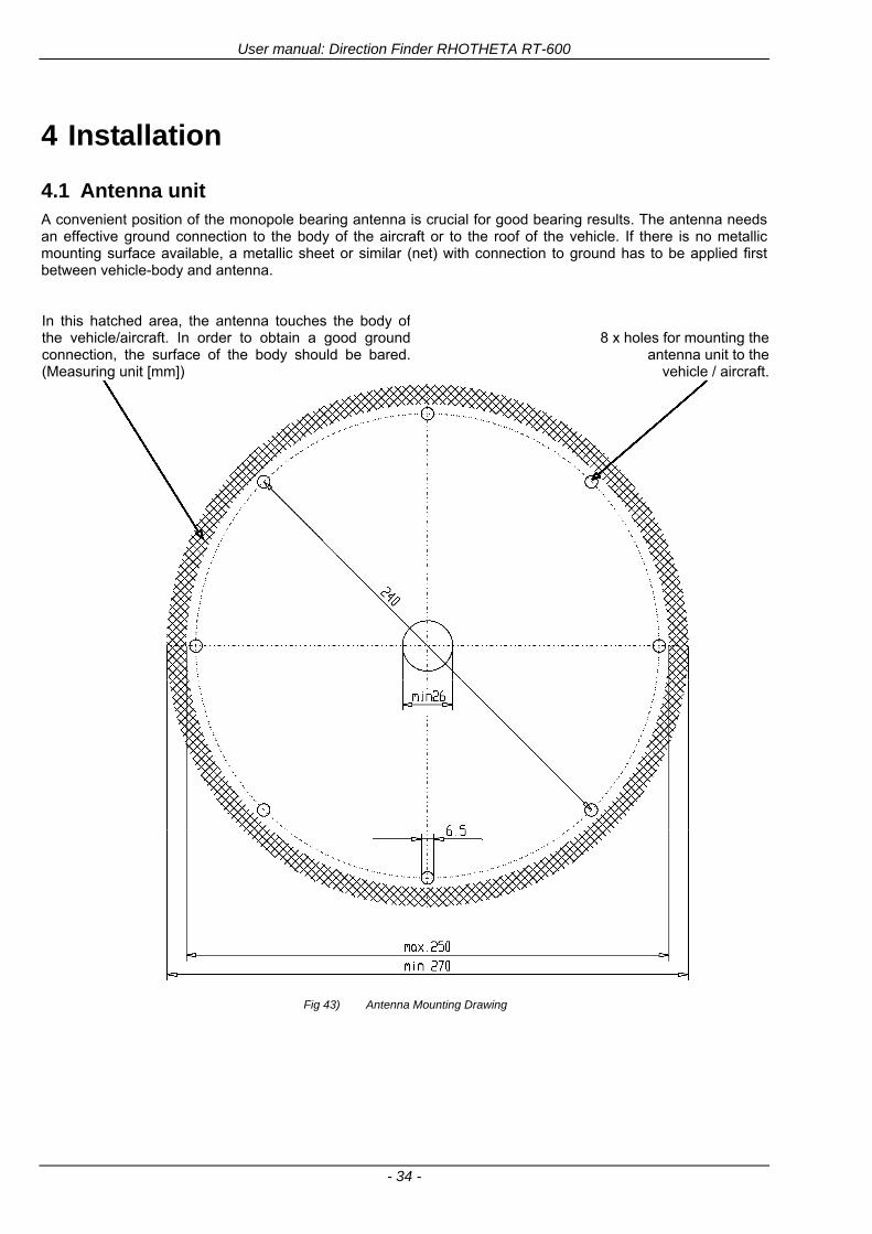
User manual Direction Finder RHOTHETA RT-600
- 34 -
4 Installation
41 Antenna unit A convenient position of the monopole bearing antenna is crucial for good bearing results The antenna needs an effective ground connection to the body of the aircraft or to the roof of the vehicle If there is no metallic mounting surface available a metallic sheet or similar (net) with connection to ground has to be applied first between vehicle-body and antenna In this hatched area the antenna touches the body ofthe vehicleaircraft In order to obtain a good groundconnection the surface of the body should be bared(Measuring unit [mm])
8 x holes for mounting the antenna unit to the
vehicle aircraft
Fig 43) Antenna Mounting Drawing
User manual Direction Finder RHOTHETA RT-600
- 35 -
411 Influence of antenna location and environment on the bearing accuracy
Recommendations concerning the practical antenna unit location on helicopters and airplanes
The bearing accuracy of the direction finder antenna unit is severely influenced (comparable to an airspeed sensor) by the environment For comparison a perfect high quality speed sensor will not indicate the true airspeed if this sensor is interfered by strong turbulences The direction finder antenna unit acts as a sensor for electromagnetic waves In the near field of this antenna unit any conductive (eg metallic) obstacle will influence the incoming wave field and create reflections which decrease the bearing accuracy These are general physical limitations concerning all types of direction finder systems To achieve the best bearing results it should be considered that the antenna unit is installed as far away as possible from any other vertically polarized conductive structure If possible there should be no reflectors within an area of 2-3 feet around the antenna unit In this worst case example the direction finder will not work properly
Fig 44) Antenna Installed in a Bad Location
In this example the antenna unit is located too close to the cable cutter of the helicopter This cutter will produce strong reflections especially as the length is equal to Lambda4 within the VHF airband
User manual Direction Finder RHOTHETA RT-600
- 36 -
Examples of properly installed direction finder antenna units
Fig 45) Antenna Installed in Good Locations
User manual Direction Finder RHOTHETA RT-600
- 37 -
42 Display and Control Unit
The display control unit may be mounted into a front panel by the means of this mounting drawing
Fig 46) DCU Mounting Drawing
(all dimensions in [mm]) To install or uninstall the display control unit perform the following steps (1) Remove the cover caps of the four rotary switches
(2) Loose the screws visible below the position of the cover caps
(3) Remove the plastic button from the axis of the four rotary switches
(4) Mount dismount the display control unit
(5) Re-install the plastic buttons on the axis of the four rotary switches
(6) Fix the screws so that the plastic buttons are fixed on the axis
(7) Re-install the cover caps on the four rotary switches
User manual Direction Finder RHOTHETA RT-600
- 38 -
43 System Interconnect Wiring Diagram (Also refer to chapter ldquoTechnical Datardquo for details)
Fig 47) System Interconnect Wiring Diagram
6-pol Amphenol plug femalePTG06SE10-6S(SQ)
max length of cable 20 m 9-pol Sub-D plug (femalemale)
User manual Direction Finder RHOTHETA RT-600
- 39 -
5 Technical Data
51 Electric features
Method of bearing Doppler-principle (3 kHz rotational frequency right left rotation)
Bearing accuracy1 plusmn 5deg RMS
Internal resolution 1deg
Bearing Sensitivity VHF AirEmergency le 25 μVm (typical)
VHF Marine le 25 μVm (typical)
UHF Emergency and ETS le 4 μVm (typical)
COSPAS-SARSAT le 4 μVm (typical)
LoJack Decoding (50 Message Error Rate) and bearing le 5 μVm (typical)
Frequency stability plusmn 20 ppm (Δff = plusmn210-6)
Reception frequencies
SAR version (Standard)
Frequency Options
VHF Emergency Band 118000 to 124000 MHz (833 kHz steps AM)
VHF Marine Band 154000 to 163000 MHz ( 500 kHz steps FM) (channel 16 selectable via channel no)
UHF Emergency Band 240000 to 246000 MHz (2500 kHz steps AM)
UHF FM Band 406100 to 410000 MHz ( 500 kHz steps FM)
COSPAS-SARSAT 400000 to 406092 MHz Including 406022 to 406076 MHz (Channel A S)
F1 VHF Air Band 118000 to 136992 MHz
F2 extended VHF Marine Band 137000 to 224995 MHz
F3 extended UHF Air Band 225000 to 399975 MHz
F4 additional UHF FM Band 406100 to 470000 MHz
Reception frequencies
LAW Enforcement version
Frequency Options
VHF Emergency Band 118000 to 124000 MHz (833 kHz steps AM)
VHF Marine Band 154000 to 163000 MHz (500 kHz steps FM) (channel 16 selectable via channel no)
LoJack 164000 to 174000 MHz (125 kHz steps FM)
ETS 216000 to 220000 MHz (10125 kHz AM)
COSPAS-SARSAT 400000 to 406092 MHz Including 406022 to 406076 MHz (Channel A S)
F1VHF Air Band 118000 to 136992 MHz
F2 extended VHF Marine Band 137000 to 163000 MHz
COSPAS-SARSAT fast scan mode
Full automatic detection of any active COSPAS-SARSAT channel A to S within 400 ms
COSPAS-SARSAT decoding
Reception and decoding of COSPAS-SARSAT data signal (112 or 144 bit) specified according to COSPAS-SARSAT
LoJack decoding Selectable LoJack ID display and selective active filtering
Special scanning modes
complete maritime ship band scanning within 3 s (channel 01 hellip 88 also frequencies between 2 channels are included)
1With undisturbed wave field and sufficient field strength Measuring by changing the angle of incidence with the antenna rotating on a revolving table in order to eliminate environmental influences on the results No modulation
User manual Direction Finder RHOTHETA RT-600
- 40 -
Bearable modulation A3E F3E A3X (ELT-modulation) F1D G2D COSPAS-SARSAT Bearing largely independent of modulation
Polarization Vertical
Polarization error 5deg at 60deg field vector rotation
Garbling cone Ca 30deg to the vertical
Time of response2 50 ms (with sufficient reception field strength)
LC-graphic display 128 x 64 pixels supertwist transflective extended range of temperature dark-blue display on yellow-green background background light Freely adjustable (exponential) dimming of brightness
NVG cockpit design Fully compatible NVIS Green B display Control Unit optional
Operating voltage 275 V nominal 12 V to 35 V DC
Current consumption LCD-background light Off max 500 mA (12 V DC) max 250 mA (24 V DC)
LCD-background light 100 max 750 mA (12 V DC) max 350 mA (24 V DC)
LCD-background light 100 max 900 mA (12 V DC) with NVG Option max 400 mA (24 V DC)
Audio out For external speaker approx 2 W (4 Ω)
Serial data interface Serial interface RS-232 (9600 baud 8 data bits 1 stop bit no parity)
2Very weak signals can considerably increase the time of response
User manual Direction Finder RHOTHETA RT-600
- 41 -
52 Interface External connections (optional at Sub-D 9-pol Male connector)
Dimming
Pin 8
external voltage input for variable dimming of legends
(optional)
Analog input signal for variable control of the legends illumination Input voltage range is freely adjustable in the range of 15 hellip 28 V in the setup menu Refer to chapter ldquoSetup Pagerdquo Default setting 8 hellip28 V (8 V = Off 28 V = max dimming for legends)
Input Impedance gt 50 k
Pin 6 night status line for LCD
dimming (optional)
Low-active (as example switch to ground) At input voltage lt 25 VDC the LCD dimming operates in nightNVG mode Maximum brightness ca 4 of daydefault mode brightness
Input Impedance gt 50 k
Pin 4 NVG status line for LCD
dimming (optional)
Low-active (as example switch to ground) At input voltage lt 25 VDC the LCD dimming operates in nightNVG mode Maximum brightness ca 4 of daydefault mode brightness
Input Impedance gt 50 k
AudioLF
Pin 7 Audio output signal
AC coupled voltage source with very low inner resistance Maximum output voltage ca 8 VPP = 283V RMS at maximum Volume Maximum output power ca 2 W with 4 speaker
If a headphone is connected ([32hellip600] 100mW) we recommend using a resistor (18 025 W) between audio output and headphone to prevent damage of the headphone
Serial interface RS232 (9600 baud 8 data bits 1 stop bit no parity)
Pin 3 TXD Serial output (ca plusmn10 V)
Pin 2 RXD Serial input (ca plusmn10 V)
User manual Direction Finder RHOTHETA RT-600
- 42 -
53 Mechanical features
Temperature range
Display Control Unit permissible operating temperature3 -20 degC +60 degC permissible storage temperature -30 degC +80 degC
Antenna Unit permissible operating temperature3 -40 degC +60 degC permissible storage temperature -55 degC +80 degC
Protective system Antenna Unit IP 67
Weights Display Control Unit 250 g Antenna Unit 2000 g
Dimensions Display Control Unit 82 mm x 82 mm x 43 mm (width x height x depth) Antenna Unit 270 mm x 185 mm
Fig 48) DCU Mechanical Drawing (all dimensions in [mm])
3 For temperatures lower than ndash10deg C a warm-up period of 15 min should be allowed
User manual Direction Finder RHOTHETA RT-600
- 43 -
Fig 49) AU Mechanical Drawing (all dimensions in [mm])
User manual Direction Finder RHOTHETA RT-600
- 44 -
6 Appendix
61 Frequency Ranges
User manual Direction Finder RHOTHETA RT-600
- 45 -
62 Frequencies of channels on maritime band (only for standard [A] version) Frequency-range of the RT-600 in the maritime band 156000 MHz 162025 MHz
Channel No frequency (ship - station) Frequency (coast - station)
1 156050 MHz 160650 MHz 2 156100 MHz 160700 MHz 3 156150 MHz 160750 MHz 4 156200 MHz 160800 MHz 5 156250 MHz 160850 MHz 6 156300 MHz 160900 MHz 7 156350 MHz 160950 MHz 8 156400 MHz 9 156450 MHz
10 156500 MHz 11 156550 MHz 12 156600 MHz 13 156650 MHz 14 156700 MHz 15 156750 MHz 16 156800 MHz 17 156850 MHz 18 156900 MHz 161500 MHz 19 156950 MHz 161550 MHz 20 157000 MHz 161600 MHz 21 157050 MHz 161650 MHz 22 157100 MHz 161700 MHz 23 157150 MHz 161750 MHz 24 157200 MHz 161800 MHz 25 157250 MHz 161850 MHz 26 157300 MHz 161900 MHz 27 157350 MHz 161950 MHz 28 157400 MHz 162000 MHz 60 156025 MHz 160625 MHz 61 156075 MHz 160675 MHz 62 156125 MHz 160725 MHz 63 156175 MHz 160775 MHz 64 156225 MHz 160825 MHz 65 156275 MHz 160875 MHz 66 156325 MHz 160925 MHz 67 156375 MHz 68 156425 MHz 69 156475 MHz 70 156525 MHz 71 156575 MHz 72 156625 MHz 73 156675 MHz 74 156725 MHz 75 156775 MHz 76 156825 MHz 77 156875 MHz 78 156925 MHz 161525 MHz 79 156975 MHz 161575 MHz 80 157025 MHz 161625 MHz 81 157075 MHz 161675 MHz 82 157125 MHz 161725 MHz 83 157175 MHz 161775 MHz 84 157225 MHz 161825 MHz 85 157275 MHz 161875 MHz 86 157325 MHz 161925 MHz 87 157375 MHz 161975 MHz 88 157425 MHz 162025 MHz
User manual Direction Finder RHOTHETA RT-600
- 46 -
63 Serial interface data protocol (short description)
631 General
Interface parameters RS232 9600 Baud 8 databits 1 stopbit no parity LSB sent first Timing of serial data For accurate use of the serial data (even for the optional serial input commands) the correct timing is mandatory The DCU (Display Control Unit) sends out via the RS-232 Pins (see 43 System Interconnect Wiring Diagram page 38) cyclic and autonomous every approx 250300 ms a binary data stream which contains all relevant DF-bearing information The output data contains one or two blocks of binary data (see next picture with accordingly description) The optional serial input is only used if changes (as example frequency change) are done by additional remote control units
Fig 50) Timing of serial data
Serial standard output
This output data is always available and contains all relevant DF-bearing data For detailed content see page 47
Optional extended serial output
This data contains some additional information like as example CospasSarsat or LoJack decoding and ID data For detailed content see page 50 The data is only available with DCU Software [Rev ge 320] and if this optional data block is configured as ON = enabled (see Setup Edit Page point (10) )
Even to avoid compatibility problems with already existing older remote control software it is possible to disable switch off this additional data block (see Setup Edit Page point (10) )
Optional serial input
Only used for optional commands to control DCU parameters If as example the direction finder frequency is changed remotely there is send to the DCU one time this data block with the new frequency For detailed content see page 52
User manual Direction Finder RHOTHETA RT-600
- 47 -
632 Serial standard output (protocol description)
Specification serial standard output
The binary data stream with a length of 39 bytes starts with a header byte (value = hex 0xA0 as ID for DF Mode) The next bytes contain different values for status bearing information and also service The last byte is used for data stream checksum control Remark This is a binary data protocol So every byte value from 0dec hellip 255dec (0x00 hellip 0xFF) is possible Because of this it is not allowed to realize a start byte detection by the content (0xA0) The idle line detection is recommended for detection the end of message Register of databytes (for details see next page)
byte no
[0] Header = 0xA0 Id for DF Mode
[1] Number = 39 = bytes in the complete message (including header and checksumbyte)
[2] Status (1) HSB [x|x|x|x|x|x|x|x] LSB | | | | | | | --gt (0) Receiving | | | | | | ----gt (1) Squelch controlled by AU (X) | | | | | ------gt (2) Permission RL Calibration | | | | --------gt (3) Line Night | | | ----------gt (4) Line NVG | | ------------gt (5) Dimming External | --------------gt (6) Autosquelch Active ----------------gt (7) 0=Standard Version 1=LE Version
[3] Status (2) HSB [x|x|x|x|x|x|x|x] LSB | ----------------gt (7) 0=Standard 1=extended serial dataprotocol = ONactive
[45] Error (Bits[120])
[6] Actual DCU Page
[7] Volume [0hellip100]
[811] Frequency [Hz]
[12] Active Band
[13] Actual Squelchlevel [0hellip60]
[14] Audio-Line amp_NF_Test Output
[15] (Not used)
[1617] Voltage_DCU ([0hellip335]=[0 hellip 335]V
[1819] Voltage_AU ([0hellip255]=[0 hellip 255]V
[20] Temperature_AU [-68hellip+127]degC
[21] Frequency Offset [-99hellip+99]
[2225] ServiceTest values (mode dependent test values for service only)
26 (Not used reserved)
[27] Level [0hellip100]
[2829] Bearing Averaged [0hellip359]deg relative
[3031] Bearing Live_Min [0hellip359]deg relative
[3233] Bearing Live_Max [0hellip359]deg relative
[34] Test Value PS-RAM Right Rotation[0hellip178] (for service only)
[35] Test Value PS-RAM Left Rotation [0hellip178] (for service only)
[3637] (Not used reserved)
[38] Checksum is the 2rsquos complement of the modulo-256 sum of all bytes without checksum-byte [0n-1]
User manual Direction Finder RHOTHETA RT-600
- 48 -
Detailed Description of important values for practical use
Status byte [2] Receiving Bit 0 of this value (LSB) indicates signal receiving Bit 0 = 0 then no signal is received and so on no bearing is available Bit 0 = 1 then bearing is possible Bit 1 if(1) then Squelch is controlled by AU (active at modes CospasSarsat Decode CospasSarsat Scanning LoJack with Filter=ID only)
Error bytes [4hellip5] 16 bit value each set bit corresponds to the error no (Refer to the chapter Error messages) Example - 0x0000 No error - 0x0800 Bit No 11 Set ( = No AU Error)
Actual DCU Page byte [6] indicates actual operating mode of DCU 0 = Standard bearing page 1 = Frequency memory page 2 = CospasSarsat decoding page 3 = LoJack decoding page (ID edit)
Frequency bytes [8hellip11] 32 bit value actual adjusted frequency [Hz] Example - 0x073DF160 1215000000 121500 MHz
Active Band Standard Version [A] 0=VHF Airband 1=VHF Marineband sea 2=VHF Marineband coast 3=UHV Airband 4=CospasSarsat LE Version [L] 0=VHF Airband 1=LoJack 2=Lifesaver 3=ETS 4=CospasSarsat
Actual Squelchlevel byte [13] Range [0hellip60] without signal the actual squelchlevel should always be adjusted a little bit over the noise level (Refer to the chapter Squelch operation)
Level byte [27] Range [099] actual receiving level (without signal this value is equal to the noise level) If a signal is received then this value corresponds to the signal strength of this signal
Relative Bearing averaged byte [2829] 16 bit value Range [0hellip359 0xFFFF] if the value = 0xFFFF then no valid bearing is available otherwise this value contains the actual averaged bearing information in Deg [0deg359deg] Example - 0X0114 276deg bearing (= left side oriented to heading)
Bearing Live MinMax byte[3031] amp [3233] - 16 bit values Range [0hellip359 0xFFFF] Only for signal quality or additional information ndash NOT recommended for bearing indication The relative live bearing field contains the maxmin bearing in degrees without averaging The relative live bearing reacts faster than the normal relative bearing but it has not the precision of the averaged bearing The MinMax Bearing Values are calculated within a time period of approx 250 ms If they are very close together (for example ldquo124rdquo and ldquo128rdquo degrees) then the signal quality is quite good A wide span of the minmax values (for example ldquo97rdquo and ldquo162rdquo) shows very noisy but nevertheless bearable signal quality
User manual Direction Finder RHOTHETA RT-600
- 49 -
633 DCU Info output (protocol description)
Specification DCU Info output
Remark This protocol is only available while the SetupEdit page is activated at the DCU
byte no
[0] Header = 0xAF Id for DCU Info Mode
[1] Number = 39 = bytes in the complete message (including header and checksumbyte)
[2]
(see standard output) [3]
[45]
[621] Info String of 15 byteschars the string contains Information about Unit Variant Software Version and Serial No
Example Byte [318] =
|--AU ID---||Var-||---Software Version---| |-------------- Serial No---------------| [0x44][0x55][0x41][0x33][0x2E][0x33][0x30][0x3A][0x20][0x20][0x30][0x31][0x32][0x33][0x34][0x00] rsquoDrsquo rsquoUrsquo rsquoArsquo rsquo3rsquo rsquorsquo rsquo3rsquo rsquo0rsquo rsquorsquo rsquo rsquo rsquo rsquo rsquo0rsquo rsquo1rsquo rsquo2rsquo rsquo3rsquo rsquo4rsquo rsquoENDrsquo | | | | __________________ | | ________________________ | n n n | | n n n n n | (Software Version) | | (Serial No) | gt rsquoArsquo = Standard Variant gt rsquoLrsquo = Law Enforcement Variant
User manual Direction Finder RHOTHETA RT-600
- 50 -
634 Optional extended serial output (protocol description)
The data content depends on the actual mode of the direction finder To get special data the direction finder has first to be switched to the equivalent mode
COSPAS-SARSAT Decoding data
This data is only available and valid if Display Control Unit with actual software Rev ge 320 (see Power-On procedure page 10) Configuration of Extended serial = ON (see Setup Edit Page point (10) ) Direction Finder COSPAS-SARSAT decoding mode is activated by selecting the corresponding page
(see COSPAS-SARSAT Decode Window page 20 and page 21) and so on Header (byte 0 of data) = 0x91
A valid COSPAS-SARSAT decoding data protocol is always marked by the first data byte (header = 0x91) Always after receiving and decoding of a valid COSPAS-SARSAT pulse the complete data protocol with 33 bytes is send out one time
Byte No
[0] Header = 0x91 (Identification for CPSarsat decoding mode)
[1] Number of bytes - 7 if no decoded pulse is available - 33 if new pulse was received and is available
[2] Error
[3] Bit[0] - 0 =gt No new 406 MSG (decoded data) available - 1 =gt New valid 406 MSG available (Sync amp Frame Ok) Check Error Status for Bit-Errors
Bit[61] AutoSquelch Level valid range [060] ( decimal)
Bit[7] = 1 Squelch controlled by AU
[4] Signallevel of received signal valid range [099] ( decimal)
[5] Voltage of Antenna Unit Power Supply input valid range [80255] (decimal = 80 255 V DC)
[6] Temperature inside Antenna Unit valid range [-50+100] (degC signed byte value)
The following databytes are only available if a correct CPSarsat puls gets received and decoded with correct checksum
[724] 18 x Databytes complete orginal CPSarsat 406 decoded message (144 bit)
Databyte Nr [ Byte 7 ] [ Byte 8 ] [Byte9 Byte24] 406 MSG Bit Nr [1 2 3 4 5 6 7 8] [9 10 11 12 13 14 15 16] [17 144]
[25] SN-Flag valid values 0x53=rsquoSrsquo 0x4E=rsquoNrsquo 0x2D=rsquo-rsquo if no GPS data available
GPS-Position Latitude
[26] Deg valid values [090] (decimal Deg) 0xFF if no GPS data available
[27] Min valid values [059] (decimal Deg) 0xFF if no GPS data available
[28] Sec valid values [059] (decimal Deg) 0xFF if no GPS data available
[29] WE-Flag valid values 0x57=rsquoWrsquo 0x45=rsquoErsquo 0x2D=rsquo-rsquo if no GPS data available
GPS-Position Longitude
[30] Deg valid values [0180] (decimal Deg) 0xFF if no GPS data available
[31] Min valid values [059] (decimal Deg) 0xFF if no GPS data available
[32] Sec valid values [059] (decimal Deg) 0xFF if no GPS data available
User manual Direction Finder RHOTHETA RT-600
- 51 -
LoJack ID data
This data is only available and valid if Display Control Unit with actual software Rev ge 320 (see Power-On procedure page 10) Direction Finder of variant [L] Law Enforcement Configuration of Extended serial = ON (see Setup Edit Page point (10) ) Direction Finder is working with active LoJack gtID Filterlt Header (byte 0 of data) = 0x93 or 0x94
Valid LoJack ID decoding data is always marked by the first data byte (header = 0x93 or 0x94)
Byte No
[0] Header = 0x93 LoJack ID editing sub-page is selected Filter = VLU all valid and received LoJack pulses are indicated = 0x94 Lojack Decode amp DF Mode with active Filter = ID
[1] Number of bytes in the complete data stream - decimal 26 = default value
[2] Nonrelevant
[3] Bit[0] Receiving OnOff - 0 =gt No Receiving no bearing - 1 =gt new LoJack pulse received
[412] Nonrelevant
[1317] Lojack ID
Replay Code 5 x ASCII Chars ldquoNo BIOZrdquo set
Example ASCII = ldquo000R1rdquo
18 Receiver Level Out Max [099]
19
LoJack Decoder Status [07] - 0 Off - 1 Wait for Preamble - 2 Preamble Ok - 3 FlagPattern Ok - 4 Data BitError gt 1 - 5 Data Ok (No VLU) - 6 VLU Ok - 7 ID Ok (Filter=IDONLY)
[2025] Nonrelevant
Remark Only if byte no [3] bit [0] gets ldquo1rdquo (Receiving On) then an active LoJack pulse is received and so on the corresponding LoJack ID valid otherwise the LoJack ID only shows the actual adjusted LoJack Filter ID of the direction finder
User manual Direction Finder RHOTHETA RT-600
- 52 -
635 Optional serial input (protocol description)
Specification serial input (optional)
The serial input is normally used for service and maintenance only Nevertheless it is possible via this interface to remote control the actual frequency and the squelchlevel of the DF system If a valid data stream is send to the DF then the actual frequency selection at the DCU is switched to Block2 AUX0 At this memory channel the new frequency is stored and used automatically (Refer to the chapter Frequency Selection Page) If the frequency is changed (by one valid data stream) no more serial input is necessary The actual frequency can be changed again at any time by manual operation at the DCU The timing of serial input (if used) is strictly fixed The optional serial input has to take place directly after a complete serial output (max 50 ms delay time) If a new changed frequency is commanded to the DCU via this serial input interface it can take up to 1 sec of time until this new frequency is ready for operationbearing It is strictly not recommended to use the frequency remote control for any scan mode The frequency control has to be used for static frequency change only Register of databytes
byte no
[0] Header 0xC0
[1] Number of bytes in the complete message (including header and checksumbyte)
[23] (not used for normal operation any byte values allowed)
[4] Volume [0100]
[58] Frequency [Hz] (frequency is rounded to the according grid automatically)
Valid Range for Standard Version Valid Range for LE Version
118000000 hellip 123000000 [Hz] 8333 kHz 118000000 hellip 123000000 [Hz] 8333 kHz
156050000 hellip 162025000 [Hz] 5000 kHz 164000000 hellip 174000000 [Hz] 8333 kHz
201000000 hellip 215995000 [Hz] 5000 kHz
240000000 hellip 246000000 [Hz] 8333 kHz 216000000 hellip 218995000 [Hz] 12500 kHz219000000 hellip 220000000 [Hz] 10000 kHz
400000000 hellip 410000000 [Hz] 8333 kHz 400000000 hellip 410000000 [Hz] 8333 kHz
[9] Squelchlevel Manual = [0hellip60] Autosql= [ -1] Warning use only for pulsed signals (as example CpSarsat LoJack)
[10] (not used for normal operation any byte values allowed)
[11] Internal Dimming [0100]
[12] Checksum is the 2rsquos complement of the modulo-256 sum of all bytes without checksum-byte [0n-1]
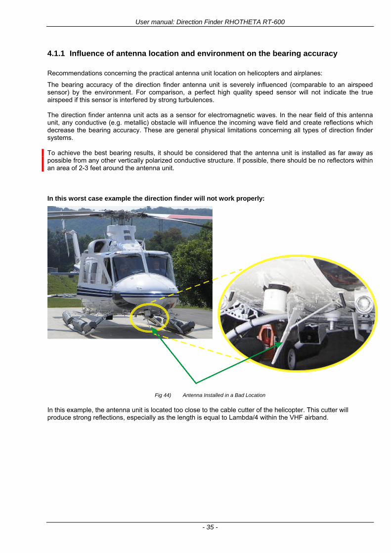
User manual Direction Finder RHOTHETA RT-600
- 35 -
411 Influence of antenna location and environment on the bearing accuracy
Recommendations concerning the practical antenna unit location on helicopters and airplanes
The bearing accuracy of the direction finder antenna unit is severely influenced (comparable to an airspeed sensor) by the environment For comparison a perfect high quality speed sensor will not indicate the true airspeed if this sensor is interfered by strong turbulences The direction finder antenna unit acts as a sensor for electromagnetic waves In the near field of this antenna unit any conductive (eg metallic) obstacle will influence the incoming wave field and create reflections which decrease the bearing accuracy These are general physical limitations concerning all types of direction finder systems To achieve the best bearing results it should be considered that the antenna unit is installed as far away as possible from any other vertically polarized conductive structure If possible there should be no reflectors within an area of 2-3 feet around the antenna unit In this worst case example the direction finder will not work properly
Fig 44) Antenna Installed in a Bad Location
In this example the antenna unit is located too close to the cable cutter of the helicopter This cutter will produce strong reflections especially as the length is equal to Lambda4 within the VHF airband
User manual Direction Finder RHOTHETA RT-600
- 36 -
Examples of properly installed direction finder antenna units
Fig 45) Antenna Installed in Good Locations
User manual Direction Finder RHOTHETA RT-600
- 37 -
42 Display and Control Unit
The display control unit may be mounted into a front panel by the means of this mounting drawing
Fig 46) DCU Mounting Drawing
(all dimensions in [mm]) To install or uninstall the display control unit perform the following steps (1) Remove the cover caps of the four rotary switches
(2) Loose the screws visible below the position of the cover caps
(3) Remove the plastic button from the axis of the four rotary switches
(4) Mount dismount the display control unit
(5) Re-install the plastic buttons on the axis of the four rotary switches
(6) Fix the screws so that the plastic buttons are fixed on the axis
(7) Re-install the cover caps on the four rotary switches
User manual Direction Finder RHOTHETA RT-600
- 38 -
43 System Interconnect Wiring Diagram (Also refer to chapter ldquoTechnical Datardquo for details)
Fig 47) System Interconnect Wiring Diagram
6-pol Amphenol plug femalePTG06SE10-6S(SQ)
max length of cable 20 m 9-pol Sub-D plug (femalemale)
User manual Direction Finder RHOTHETA RT-600
- 39 -
5 Technical Data
51 Electric features
Method of bearing Doppler-principle (3 kHz rotational frequency right left rotation)
Bearing accuracy1 plusmn 5deg RMS
Internal resolution 1deg
Bearing Sensitivity VHF AirEmergency le 25 μVm (typical)
VHF Marine le 25 μVm (typical)
UHF Emergency and ETS le 4 μVm (typical)
COSPAS-SARSAT le 4 μVm (typical)
LoJack Decoding (50 Message Error Rate) and bearing le 5 μVm (typical)
Frequency stability plusmn 20 ppm (Δff = plusmn210-6)
Reception frequencies
SAR version (Standard)
Frequency Options
VHF Emergency Band 118000 to 124000 MHz (833 kHz steps AM)
VHF Marine Band 154000 to 163000 MHz ( 500 kHz steps FM) (channel 16 selectable via channel no)
UHF Emergency Band 240000 to 246000 MHz (2500 kHz steps AM)
UHF FM Band 406100 to 410000 MHz ( 500 kHz steps FM)
COSPAS-SARSAT 400000 to 406092 MHz Including 406022 to 406076 MHz (Channel A S)
F1 VHF Air Band 118000 to 136992 MHz
F2 extended VHF Marine Band 137000 to 224995 MHz
F3 extended UHF Air Band 225000 to 399975 MHz
F4 additional UHF FM Band 406100 to 470000 MHz
Reception frequencies
LAW Enforcement version
Frequency Options
VHF Emergency Band 118000 to 124000 MHz (833 kHz steps AM)
VHF Marine Band 154000 to 163000 MHz (500 kHz steps FM) (channel 16 selectable via channel no)
LoJack 164000 to 174000 MHz (125 kHz steps FM)
ETS 216000 to 220000 MHz (10125 kHz AM)
COSPAS-SARSAT 400000 to 406092 MHz Including 406022 to 406076 MHz (Channel A S)
F1VHF Air Band 118000 to 136992 MHz
F2 extended VHF Marine Band 137000 to 163000 MHz
COSPAS-SARSAT fast scan mode
Full automatic detection of any active COSPAS-SARSAT channel A to S within 400 ms
COSPAS-SARSAT decoding
Reception and decoding of COSPAS-SARSAT data signal (112 or 144 bit) specified according to COSPAS-SARSAT
LoJack decoding Selectable LoJack ID display and selective active filtering
Special scanning modes
complete maritime ship band scanning within 3 s (channel 01 hellip 88 also frequencies between 2 channels are included)
1With undisturbed wave field and sufficient field strength Measuring by changing the angle of incidence with the antenna rotating on a revolving table in order to eliminate environmental influences on the results No modulation
User manual Direction Finder RHOTHETA RT-600
- 40 -
Bearable modulation A3E F3E A3X (ELT-modulation) F1D G2D COSPAS-SARSAT Bearing largely independent of modulation
Polarization Vertical
Polarization error 5deg at 60deg field vector rotation
Garbling cone Ca 30deg to the vertical
Time of response2 50 ms (with sufficient reception field strength)
LC-graphic display 128 x 64 pixels supertwist transflective extended range of temperature dark-blue display on yellow-green background background light Freely adjustable (exponential) dimming of brightness
NVG cockpit design Fully compatible NVIS Green B display Control Unit optional
Operating voltage 275 V nominal 12 V to 35 V DC
Current consumption LCD-background light Off max 500 mA (12 V DC) max 250 mA (24 V DC)
LCD-background light 100 max 750 mA (12 V DC) max 350 mA (24 V DC)
LCD-background light 100 max 900 mA (12 V DC) with NVG Option max 400 mA (24 V DC)
Audio out For external speaker approx 2 W (4 Ω)
Serial data interface Serial interface RS-232 (9600 baud 8 data bits 1 stop bit no parity)
2Very weak signals can considerably increase the time of response
User manual Direction Finder RHOTHETA RT-600
- 41 -
52 Interface External connections (optional at Sub-D 9-pol Male connector)
Dimming
Pin 8
external voltage input for variable dimming of legends
(optional)
Analog input signal for variable control of the legends illumination Input voltage range is freely adjustable in the range of 15 hellip 28 V in the setup menu Refer to chapter ldquoSetup Pagerdquo Default setting 8 hellip28 V (8 V = Off 28 V = max dimming for legends)
Input Impedance gt 50 k
Pin 6 night status line for LCD
dimming (optional)
Low-active (as example switch to ground) At input voltage lt 25 VDC the LCD dimming operates in nightNVG mode Maximum brightness ca 4 of daydefault mode brightness
Input Impedance gt 50 k
Pin 4 NVG status line for LCD
dimming (optional)
Low-active (as example switch to ground) At input voltage lt 25 VDC the LCD dimming operates in nightNVG mode Maximum brightness ca 4 of daydefault mode brightness
Input Impedance gt 50 k
AudioLF
Pin 7 Audio output signal
AC coupled voltage source with very low inner resistance Maximum output voltage ca 8 VPP = 283V RMS at maximum Volume Maximum output power ca 2 W with 4 speaker
If a headphone is connected ([32hellip600] 100mW) we recommend using a resistor (18 025 W) between audio output and headphone to prevent damage of the headphone
Serial interface RS232 (9600 baud 8 data bits 1 stop bit no parity)
Pin 3 TXD Serial output (ca plusmn10 V)
Pin 2 RXD Serial input (ca plusmn10 V)
User manual Direction Finder RHOTHETA RT-600
- 42 -
53 Mechanical features
Temperature range
Display Control Unit permissible operating temperature3 -20 degC +60 degC permissible storage temperature -30 degC +80 degC
Antenna Unit permissible operating temperature3 -40 degC +60 degC permissible storage temperature -55 degC +80 degC
Protective system Antenna Unit IP 67
Weights Display Control Unit 250 g Antenna Unit 2000 g
Dimensions Display Control Unit 82 mm x 82 mm x 43 mm (width x height x depth) Antenna Unit 270 mm x 185 mm
Fig 48) DCU Mechanical Drawing (all dimensions in [mm])
3 For temperatures lower than ndash10deg C a warm-up period of 15 min should be allowed
User manual Direction Finder RHOTHETA RT-600
- 43 -
Fig 49) AU Mechanical Drawing (all dimensions in [mm])
User manual Direction Finder RHOTHETA RT-600
- 44 -
6 Appendix
61 Frequency Ranges
User manual Direction Finder RHOTHETA RT-600
- 45 -
62 Frequencies of channels on maritime band (only for standard [A] version) Frequency-range of the RT-600 in the maritime band 156000 MHz 162025 MHz
Channel No frequency (ship - station) Frequency (coast - station)
1 156050 MHz 160650 MHz 2 156100 MHz 160700 MHz 3 156150 MHz 160750 MHz 4 156200 MHz 160800 MHz 5 156250 MHz 160850 MHz 6 156300 MHz 160900 MHz 7 156350 MHz 160950 MHz 8 156400 MHz 9 156450 MHz
10 156500 MHz 11 156550 MHz 12 156600 MHz 13 156650 MHz 14 156700 MHz 15 156750 MHz 16 156800 MHz 17 156850 MHz 18 156900 MHz 161500 MHz 19 156950 MHz 161550 MHz 20 157000 MHz 161600 MHz 21 157050 MHz 161650 MHz 22 157100 MHz 161700 MHz 23 157150 MHz 161750 MHz 24 157200 MHz 161800 MHz 25 157250 MHz 161850 MHz 26 157300 MHz 161900 MHz 27 157350 MHz 161950 MHz 28 157400 MHz 162000 MHz 60 156025 MHz 160625 MHz 61 156075 MHz 160675 MHz 62 156125 MHz 160725 MHz 63 156175 MHz 160775 MHz 64 156225 MHz 160825 MHz 65 156275 MHz 160875 MHz 66 156325 MHz 160925 MHz 67 156375 MHz 68 156425 MHz 69 156475 MHz 70 156525 MHz 71 156575 MHz 72 156625 MHz 73 156675 MHz 74 156725 MHz 75 156775 MHz 76 156825 MHz 77 156875 MHz 78 156925 MHz 161525 MHz 79 156975 MHz 161575 MHz 80 157025 MHz 161625 MHz 81 157075 MHz 161675 MHz 82 157125 MHz 161725 MHz 83 157175 MHz 161775 MHz 84 157225 MHz 161825 MHz 85 157275 MHz 161875 MHz 86 157325 MHz 161925 MHz 87 157375 MHz 161975 MHz 88 157425 MHz 162025 MHz
User manual Direction Finder RHOTHETA RT-600
- 46 -
63 Serial interface data protocol (short description)
631 General
Interface parameters RS232 9600 Baud 8 databits 1 stopbit no parity LSB sent first Timing of serial data For accurate use of the serial data (even for the optional serial input commands) the correct timing is mandatory The DCU (Display Control Unit) sends out via the RS-232 Pins (see 43 System Interconnect Wiring Diagram page 38) cyclic and autonomous every approx 250300 ms a binary data stream which contains all relevant DF-bearing information The output data contains one or two blocks of binary data (see next picture with accordingly description) The optional serial input is only used if changes (as example frequency change) are done by additional remote control units
Fig 50) Timing of serial data
Serial standard output
This output data is always available and contains all relevant DF-bearing data For detailed content see page 47
Optional extended serial output
This data contains some additional information like as example CospasSarsat or LoJack decoding and ID data For detailed content see page 50 The data is only available with DCU Software [Rev ge 320] and if this optional data block is configured as ON = enabled (see Setup Edit Page point (10) )
Even to avoid compatibility problems with already existing older remote control software it is possible to disable switch off this additional data block (see Setup Edit Page point (10) )
Optional serial input
Only used for optional commands to control DCU parameters If as example the direction finder frequency is changed remotely there is send to the DCU one time this data block with the new frequency For detailed content see page 52
User manual Direction Finder RHOTHETA RT-600
- 47 -
632 Serial standard output (protocol description)
Specification serial standard output
The binary data stream with a length of 39 bytes starts with a header byte (value = hex 0xA0 as ID for DF Mode) The next bytes contain different values for status bearing information and also service The last byte is used for data stream checksum control Remark This is a binary data protocol So every byte value from 0dec hellip 255dec (0x00 hellip 0xFF) is possible Because of this it is not allowed to realize a start byte detection by the content (0xA0) The idle line detection is recommended for detection the end of message Register of databytes (for details see next page)
byte no
[0] Header = 0xA0 Id for DF Mode
[1] Number = 39 = bytes in the complete message (including header and checksumbyte)
[2] Status (1) HSB [x|x|x|x|x|x|x|x] LSB | | | | | | | --gt (0) Receiving | | | | | | ----gt (1) Squelch controlled by AU (X) | | | | | ------gt (2) Permission RL Calibration | | | | --------gt (3) Line Night | | | ----------gt (4) Line NVG | | ------------gt (5) Dimming External | --------------gt (6) Autosquelch Active ----------------gt (7) 0=Standard Version 1=LE Version
[3] Status (2) HSB [x|x|x|x|x|x|x|x] LSB | ----------------gt (7) 0=Standard 1=extended serial dataprotocol = ONactive
[45] Error (Bits[120])
[6] Actual DCU Page
[7] Volume [0hellip100]
[811] Frequency [Hz]
[12] Active Band
[13] Actual Squelchlevel [0hellip60]
[14] Audio-Line amp_NF_Test Output
[15] (Not used)
[1617] Voltage_DCU ([0hellip335]=[0 hellip 335]V
[1819] Voltage_AU ([0hellip255]=[0 hellip 255]V
[20] Temperature_AU [-68hellip+127]degC
[21] Frequency Offset [-99hellip+99]
[2225] ServiceTest values (mode dependent test values for service only)
26 (Not used reserved)
[27] Level [0hellip100]
[2829] Bearing Averaged [0hellip359]deg relative
[3031] Bearing Live_Min [0hellip359]deg relative
[3233] Bearing Live_Max [0hellip359]deg relative
[34] Test Value PS-RAM Right Rotation[0hellip178] (for service only)
[35] Test Value PS-RAM Left Rotation [0hellip178] (for service only)
[3637] (Not used reserved)
[38] Checksum is the 2rsquos complement of the modulo-256 sum of all bytes without checksum-byte [0n-1]
User manual Direction Finder RHOTHETA RT-600
- 48 -
Detailed Description of important values for practical use
Status byte [2] Receiving Bit 0 of this value (LSB) indicates signal receiving Bit 0 = 0 then no signal is received and so on no bearing is available Bit 0 = 1 then bearing is possible Bit 1 if(1) then Squelch is controlled by AU (active at modes CospasSarsat Decode CospasSarsat Scanning LoJack with Filter=ID only)
Error bytes [4hellip5] 16 bit value each set bit corresponds to the error no (Refer to the chapter Error messages) Example - 0x0000 No error - 0x0800 Bit No 11 Set ( = No AU Error)
Actual DCU Page byte [6] indicates actual operating mode of DCU 0 = Standard bearing page 1 = Frequency memory page 2 = CospasSarsat decoding page 3 = LoJack decoding page (ID edit)
Frequency bytes [8hellip11] 32 bit value actual adjusted frequency [Hz] Example - 0x073DF160 1215000000 121500 MHz
Active Band Standard Version [A] 0=VHF Airband 1=VHF Marineband sea 2=VHF Marineband coast 3=UHV Airband 4=CospasSarsat LE Version [L] 0=VHF Airband 1=LoJack 2=Lifesaver 3=ETS 4=CospasSarsat
Actual Squelchlevel byte [13] Range [0hellip60] without signal the actual squelchlevel should always be adjusted a little bit over the noise level (Refer to the chapter Squelch operation)
Level byte [27] Range [099] actual receiving level (without signal this value is equal to the noise level) If a signal is received then this value corresponds to the signal strength of this signal
Relative Bearing averaged byte [2829] 16 bit value Range [0hellip359 0xFFFF] if the value = 0xFFFF then no valid bearing is available otherwise this value contains the actual averaged bearing information in Deg [0deg359deg] Example - 0X0114 276deg bearing (= left side oriented to heading)
Bearing Live MinMax byte[3031] amp [3233] - 16 bit values Range [0hellip359 0xFFFF] Only for signal quality or additional information ndash NOT recommended for bearing indication The relative live bearing field contains the maxmin bearing in degrees without averaging The relative live bearing reacts faster than the normal relative bearing but it has not the precision of the averaged bearing The MinMax Bearing Values are calculated within a time period of approx 250 ms If they are very close together (for example ldquo124rdquo and ldquo128rdquo degrees) then the signal quality is quite good A wide span of the minmax values (for example ldquo97rdquo and ldquo162rdquo) shows very noisy but nevertheless bearable signal quality
User manual Direction Finder RHOTHETA RT-600
- 49 -
633 DCU Info output (protocol description)
Specification DCU Info output
Remark This protocol is only available while the SetupEdit page is activated at the DCU
byte no
[0] Header = 0xAF Id for DCU Info Mode
[1] Number = 39 = bytes in the complete message (including header and checksumbyte)
[2]
(see standard output) [3]
[45]
[621] Info String of 15 byteschars the string contains Information about Unit Variant Software Version and Serial No
Example Byte [318] =
|--AU ID---||Var-||---Software Version---| |-------------- Serial No---------------| [0x44][0x55][0x41][0x33][0x2E][0x33][0x30][0x3A][0x20][0x20][0x30][0x31][0x32][0x33][0x34][0x00] rsquoDrsquo rsquoUrsquo rsquoArsquo rsquo3rsquo rsquorsquo rsquo3rsquo rsquo0rsquo rsquorsquo rsquo rsquo rsquo rsquo rsquo0rsquo rsquo1rsquo rsquo2rsquo rsquo3rsquo rsquo4rsquo rsquoENDrsquo | | | | __________________ | | ________________________ | n n n | | n n n n n | (Software Version) | | (Serial No) | gt rsquoArsquo = Standard Variant gt rsquoLrsquo = Law Enforcement Variant
User manual Direction Finder RHOTHETA RT-600
- 50 -
634 Optional extended serial output (protocol description)
The data content depends on the actual mode of the direction finder To get special data the direction finder has first to be switched to the equivalent mode
COSPAS-SARSAT Decoding data
This data is only available and valid if Display Control Unit with actual software Rev ge 320 (see Power-On procedure page 10) Configuration of Extended serial = ON (see Setup Edit Page point (10) ) Direction Finder COSPAS-SARSAT decoding mode is activated by selecting the corresponding page
(see COSPAS-SARSAT Decode Window page 20 and page 21) and so on Header (byte 0 of data) = 0x91
A valid COSPAS-SARSAT decoding data protocol is always marked by the first data byte (header = 0x91) Always after receiving and decoding of a valid COSPAS-SARSAT pulse the complete data protocol with 33 bytes is send out one time
Byte No
[0] Header = 0x91 (Identification for CPSarsat decoding mode)
[1] Number of bytes - 7 if no decoded pulse is available - 33 if new pulse was received and is available
[2] Error
[3] Bit[0] - 0 =gt No new 406 MSG (decoded data) available - 1 =gt New valid 406 MSG available (Sync amp Frame Ok) Check Error Status for Bit-Errors
Bit[61] AutoSquelch Level valid range [060] ( decimal)
Bit[7] = 1 Squelch controlled by AU
[4] Signallevel of received signal valid range [099] ( decimal)
[5] Voltage of Antenna Unit Power Supply input valid range [80255] (decimal = 80 255 V DC)
[6] Temperature inside Antenna Unit valid range [-50+100] (degC signed byte value)
The following databytes are only available if a correct CPSarsat puls gets received and decoded with correct checksum
[724] 18 x Databytes complete orginal CPSarsat 406 decoded message (144 bit)
Databyte Nr [ Byte 7 ] [ Byte 8 ] [Byte9 Byte24] 406 MSG Bit Nr [1 2 3 4 5 6 7 8] [9 10 11 12 13 14 15 16] [17 144]
[25] SN-Flag valid values 0x53=rsquoSrsquo 0x4E=rsquoNrsquo 0x2D=rsquo-rsquo if no GPS data available
GPS-Position Latitude
[26] Deg valid values [090] (decimal Deg) 0xFF if no GPS data available
[27] Min valid values [059] (decimal Deg) 0xFF if no GPS data available
[28] Sec valid values [059] (decimal Deg) 0xFF if no GPS data available
[29] WE-Flag valid values 0x57=rsquoWrsquo 0x45=rsquoErsquo 0x2D=rsquo-rsquo if no GPS data available
GPS-Position Longitude
[30] Deg valid values [0180] (decimal Deg) 0xFF if no GPS data available
[31] Min valid values [059] (decimal Deg) 0xFF if no GPS data available
[32] Sec valid values [059] (decimal Deg) 0xFF if no GPS data available
User manual Direction Finder RHOTHETA RT-600
- 51 -
LoJack ID data
This data is only available and valid if Display Control Unit with actual software Rev ge 320 (see Power-On procedure page 10) Direction Finder of variant [L] Law Enforcement Configuration of Extended serial = ON (see Setup Edit Page point (10) ) Direction Finder is working with active LoJack gtID Filterlt Header (byte 0 of data) = 0x93 or 0x94
Valid LoJack ID decoding data is always marked by the first data byte (header = 0x93 or 0x94)
Byte No
[0] Header = 0x93 LoJack ID editing sub-page is selected Filter = VLU all valid and received LoJack pulses are indicated = 0x94 Lojack Decode amp DF Mode with active Filter = ID
[1] Number of bytes in the complete data stream - decimal 26 = default value
[2] Nonrelevant
[3] Bit[0] Receiving OnOff - 0 =gt No Receiving no bearing - 1 =gt new LoJack pulse received
[412] Nonrelevant
[1317] Lojack ID
Replay Code 5 x ASCII Chars ldquoNo BIOZrdquo set
Example ASCII = ldquo000R1rdquo
18 Receiver Level Out Max [099]
19
LoJack Decoder Status [07] - 0 Off - 1 Wait for Preamble - 2 Preamble Ok - 3 FlagPattern Ok - 4 Data BitError gt 1 - 5 Data Ok (No VLU) - 6 VLU Ok - 7 ID Ok (Filter=IDONLY)
[2025] Nonrelevant
Remark Only if byte no [3] bit [0] gets ldquo1rdquo (Receiving On) then an active LoJack pulse is received and so on the corresponding LoJack ID valid otherwise the LoJack ID only shows the actual adjusted LoJack Filter ID of the direction finder
User manual Direction Finder RHOTHETA RT-600
- 52 -
635 Optional serial input (protocol description)
Specification serial input (optional)
The serial input is normally used for service and maintenance only Nevertheless it is possible via this interface to remote control the actual frequency and the squelchlevel of the DF system If a valid data stream is send to the DF then the actual frequency selection at the DCU is switched to Block2 AUX0 At this memory channel the new frequency is stored and used automatically (Refer to the chapter Frequency Selection Page) If the frequency is changed (by one valid data stream) no more serial input is necessary The actual frequency can be changed again at any time by manual operation at the DCU The timing of serial input (if used) is strictly fixed The optional serial input has to take place directly after a complete serial output (max 50 ms delay time) If a new changed frequency is commanded to the DCU via this serial input interface it can take up to 1 sec of time until this new frequency is ready for operationbearing It is strictly not recommended to use the frequency remote control for any scan mode The frequency control has to be used for static frequency change only Register of databytes
byte no
[0] Header 0xC0
[1] Number of bytes in the complete message (including header and checksumbyte)
[23] (not used for normal operation any byte values allowed)
[4] Volume [0100]
[58] Frequency [Hz] (frequency is rounded to the according grid automatically)
Valid Range for Standard Version Valid Range for LE Version
118000000 hellip 123000000 [Hz] 8333 kHz 118000000 hellip 123000000 [Hz] 8333 kHz
156050000 hellip 162025000 [Hz] 5000 kHz 164000000 hellip 174000000 [Hz] 8333 kHz
201000000 hellip 215995000 [Hz] 5000 kHz
240000000 hellip 246000000 [Hz] 8333 kHz 216000000 hellip 218995000 [Hz] 12500 kHz219000000 hellip 220000000 [Hz] 10000 kHz
400000000 hellip 410000000 [Hz] 8333 kHz 400000000 hellip 410000000 [Hz] 8333 kHz
[9] Squelchlevel Manual = [0hellip60] Autosql= [ -1] Warning use only for pulsed signals (as example CpSarsat LoJack)
[10] (not used for normal operation any byte values allowed)
[11] Internal Dimming [0100]
[12] Checksum is the 2rsquos complement of the modulo-256 sum of all bytes without checksum-byte [0n-1]
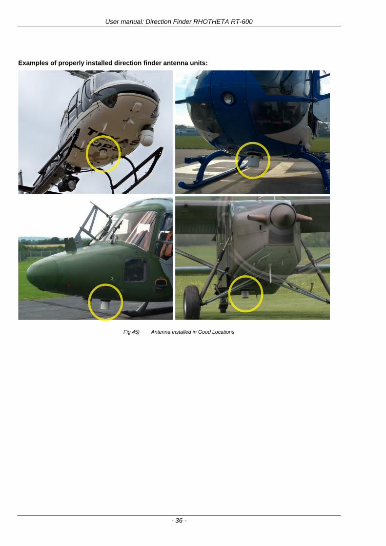
User manual Direction Finder RHOTHETA RT-600
- 36 -
Examples of properly installed direction finder antenna units
Fig 45) Antenna Installed in Good Locations
User manual Direction Finder RHOTHETA RT-600
- 37 -
42 Display and Control Unit
The display control unit may be mounted into a front panel by the means of this mounting drawing
Fig 46) DCU Mounting Drawing
(all dimensions in [mm]) To install or uninstall the display control unit perform the following steps (1) Remove the cover caps of the four rotary switches
(2) Loose the screws visible below the position of the cover caps
(3) Remove the plastic button from the axis of the four rotary switches
(4) Mount dismount the display control unit
(5) Re-install the plastic buttons on the axis of the four rotary switches
(6) Fix the screws so that the plastic buttons are fixed on the axis
(7) Re-install the cover caps on the four rotary switches
User manual Direction Finder RHOTHETA RT-600
- 38 -
43 System Interconnect Wiring Diagram (Also refer to chapter ldquoTechnical Datardquo for details)
Fig 47) System Interconnect Wiring Diagram
6-pol Amphenol plug femalePTG06SE10-6S(SQ)
max length of cable 20 m 9-pol Sub-D plug (femalemale)
User manual Direction Finder RHOTHETA RT-600
- 39 -
5 Technical Data
51 Electric features
Method of bearing Doppler-principle (3 kHz rotational frequency right left rotation)
Bearing accuracy1 plusmn 5deg RMS
Internal resolution 1deg
Bearing Sensitivity VHF AirEmergency le 25 μVm (typical)
VHF Marine le 25 μVm (typical)
UHF Emergency and ETS le 4 μVm (typical)
COSPAS-SARSAT le 4 μVm (typical)
LoJack Decoding (50 Message Error Rate) and bearing le 5 μVm (typical)
Frequency stability plusmn 20 ppm (Δff = plusmn210-6)
Reception frequencies
SAR version (Standard)
Frequency Options
VHF Emergency Band 118000 to 124000 MHz (833 kHz steps AM)
VHF Marine Band 154000 to 163000 MHz ( 500 kHz steps FM) (channel 16 selectable via channel no)
UHF Emergency Band 240000 to 246000 MHz (2500 kHz steps AM)
UHF FM Band 406100 to 410000 MHz ( 500 kHz steps FM)
COSPAS-SARSAT 400000 to 406092 MHz Including 406022 to 406076 MHz (Channel A S)
F1 VHF Air Band 118000 to 136992 MHz
F2 extended VHF Marine Band 137000 to 224995 MHz
F3 extended UHF Air Band 225000 to 399975 MHz
F4 additional UHF FM Band 406100 to 470000 MHz
Reception frequencies
LAW Enforcement version
Frequency Options
VHF Emergency Band 118000 to 124000 MHz (833 kHz steps AM)
VHF Marine Band 154000 to 163000 MHz (500 kHz steps FM) (channel 16 selectable via channel no)
LoJack 164000 to 174000 MHz (125 kHz steps FM)
ETS 216000 to 220000 MHz (10125 kHz AM)
COSPAS-SARSAT 400000 to 406092 MHz Including 406022 to 406076 MHz (Channel A S)
F1VHF Air Band 118000 to 136992 MHz
F2 extended VHF Marine Band 137000 to 163000 MHz
COSPAS-SARSAT fast scan mode
Full automatic detection of any active COSPAS-SARSAT channel A to S within 400 ms
COSPAS-SARSAT decoding
Reception and decoding of COSPAS-SARSAT data signal (112 or 144 bit) specified according to COSPAS-SARSAT
LoJack decoding Selectable LoJack ID display and selective active filtering
Special scanning modes
complete maritime ship band scanning within 3 s (channel 01 hellip 88 also frequencies between 2 channels are included)
1With undisturbed wave field and sufficient field strength Measuring by changing the angle of incidence with the antenna rotating on a revolving table in order to eliminate environmental influences on the results No modulation
User manual Direction Finder RHOTHETA RT-600
- 40 -
Bearable modulation A3E F3E A3X (ELT-modulation) F1D G2D COSPAS-SARSAT Bearing largely independent of modulation
Polarization Vertical
Polarization error 5deg at 60deg field vector rotation
Garbling cone Ca 30deg to the vertical
Time of response2 50 ms (with sufficient reception field strength)
LC-graphic display 128 x 64 pixels supertwist transflective extended range of temperature dark-blue display on yellow-green background background light Freely adjustable (exponential) dimming of brightness
NVG cockpit design Fully compatible NVIS Green B display Control Unit optional
Operating voltage 275 V nominal 12 V to 35 V DC
Current consumption LCD-background light Off max 500 mA (12 V DC) max 250 mA (24 V DC)
LCD-background light 100 max 750 mA (12 V DC) max 350 mA (24 V DC)
LCD-background light 100 max 900 mA (12 V DC) with NVG Option max 400 mA (24 V DC)
Audio out For external speaker approx 2 W (4 Ω)
Serial data interface Serial interface RS-232 (9600 baud 8 data bits 1 stop bit no parity)
2Very weak signals can considerably increase the time of response
User manual Direction Finder RHOTHETA RT-600
- 41 -
52 Interface External connections (optional at Sub-D 9-pol Male connector)
Dimming
Pin 8
external voltage input for variable dimming of legends
(optional)
Analog input signal for variable control of the legends illumination Input voltage range is freely adjustable in the range of 15 hellip 28 V in the setup menu Refer to chapter ldquoSetup Pagerdquo Default setting 8 hellip28 V (8 V = Off 28 V = max dimming for legends)
Input Impedance gt 50 k
Pin 6 night status line for LCD
dimming (optional)
Low-active (as example switch to ground) At input voltage lt 25 VDC the LCD dimming operates in nightNVG mode Maximum brightness ca 4 of daydefault mode brightness
Input Impedance gt 50 k
Pin 4 NVG status line for LCD
dimming (optional)
Low-active (as example switch to ground) At input voltage lt 25 VDC the LCD dimming operates in nightNVG mode Maximum brightness ca 4 of daydefault mode brightness
Input Impedance gt 50 k
AudioLF
Pin 7 Audio output signal
AC coupled voltage source with very low inner resistance Maximum output voltage ca 8 VPP = 283V RMS at maximum Volume Maximum output power ca 2 W with 4 speaker
If a headphone is connected ([32hellip600] 100mW) we recommend using a resistor (18 025 W) between audio output and headphone to prevent damage of the headphone
Serial interface RS232 (9600 baud 8 data bits 1 stop bit no parity)
Pin 3 TXD Serial output (ca plusmn10 V)
Pin 2 RXD Serial input (ca plusmn10 V)
User manual Direction Finder RHOTHETA RT-600
- 42 -
53 Mechanical features
Temperature range
Display Control Unit permissible operating temperature3 -20 degC +60 degC permissible storage temperature -30 degC +80 degC
Antenna Unit permissible operating temperature3 -40 degC +60 degC permissible storage temperature -55 degC +80 degC
Protective system Antenna Unit IP 67
Weights Display Control Unit 250 g Antenna Unit 2000 g
Dimensions Display Control Unit 82 mm x 82 mm x 43 mm (width x height x depth) Antenna Unit 270 mm x 185 mm
Fig 48) DCU Mechanical Drawing (all dimensions in [mm])
3 For temperatures lower than ndash10deg C a warm-up period of 15 min should be allowed
User manual Direction Finder RHOTHETA RT-600
- 43 -
Fig 49) AU Mechanical Drawing (all dimensions in [mm])
User manual Direction Finder RHOTHETA RT-600
- 44 -
6 Appendix
61 Frequency Ranges
User manual Direction Finder RHOTHETA RT-600
- 45 -
62 Frequencies of channels on maritime band (only for standard [A] version) Frequency-range of the RT-600 in the maritime band 156000 MHz 162025 MHz
Channel No frequency (ship - station) Frequency (coast - station)
1 156050 MHz 160650 MHz 2 156100 MHz 160700 MHz 3 156150 MHz 160750 MHz 4 156200 MHz 160800 MHz 5 156250 MHz 160850 MHz 6 156300 MHz 160900 MHz 7 156350 MHz 160950 MHz 8 156400 MHz 9 156450 MHz
10 156500 MHz 11 156550 MHz 12 156600 MHz 13 156650 MHz 14 156700 MHz 15 156750 MHz 16 156800 MHz 17 156850 MHz 18 156900 MHz 161500 MHz 19 156950 MHz 161550 MHz 20 157000 MHz 161600 MHz 21 157050 MHz 161650 MHz 22 157100 MHz 161700 MHz 23 157150 MHz 161750 MHz 24 157200 MHz 161800 MHz 25 157250 MHz 161850 MHz 26 157300 MHz 161900 MHz 27 157350 MHz 161950 MHz 28 157400 MHz 162000 MHz 60 156025 MHz 160625 MHz 61 156075 MHz 160675 MHz 62 156125 MHz 160725 MHz 63 156175 MHz 160775 MHz 64 156225 MHz 160825 MHz 65 156275 MHz 160875 MHz 66 156325 MHz 160925 MHz 67 156375 MHz 68 156425 MHz 69 156475 MHz 70 156525 MHz 71 156575 MHz 72 156625 MHz 73 156675 MHz 74 156725 MHz 75 156775 MHz 76 156825 MHz 77 156875 MHz 78 156925 MHz 161525 MHz 79 156975 MHz 161575 MHz 80 157025 MHz 161625 MHz 81 157075 MHz 161675 MHz 82 157125 MHz 161725 MHz 83 157175 MHz 161775 MHz 84 157225 MHz 161825 MHz 85 157275 MHz 161875 MHz 86 157325 MHz 161925 MHz 87 157375 MHz 161975 MHz 88 157425 MHz 162025 MHz
User manual Direction Finder RHOTHETA RT-600
- 46 -
63 Serial interface data protocol (short description)
631 General
Interface parameters RS232 9600 Baud 8 databits 1 stopbit no parity LSB sent first Timing of serial data For accurate use of the serial data (even for the optional serial input commands) the correct timing is mandatory The DCU (Display Control Unit) sends out via the RS-232 Pins (see 43 System Interconnect Wiring Diagram page 38) cyclic and autonomous every approx 250300 ms a binary data stream which contains all relevant DF-bearing information The output data contains one or two blocks of binary data (see next picture with accordingly description) The optional serial input is only used if changes (as example frequency change) are done by additional remote control units
Fig 50) Timing of serial data
Serial standard output
This output data is always available and contains all relevant DF-bearing data For detailed content see page 47
Optional extended serial output
This data contains some additional information like as example CospasSarsat or LoJack decoding and ID data For detailed content see page 50 The data is only available with DCU Software [Rev ge 320] and if this optional data block is configured as ON = enabled (see Setup Edit Page point (10) )
Even to avoid compatibility problems with already existing older remote control software it is possible to disable switch off this additional data block (see Setup Edit Page point (10) )
Optional serial input
Only used for optional commands to control DCU parameters If as example the direction finder frequency is changed remotely there is send to the DCU one time this data block with the new frequency For detailed content see page 52
User manual Direction Finder RHOTHETA RT-600
- 47 -
632 Serial standard output (protocol description)
Specification serial standard output
The binary data stream with a length of 39 bytes starts with a header byte (value = hex 0xA0 as ID for DF Mode) The next bytes contain different values for status bearing information and also service The last byte is used for data stream checksum control Remark This is a binary data protocol So every byte value from 0dec hellip 255dec (0x00 hellip 0xFF) is possible Because of this it is not allowed to realize a start byte detection by the content (0xA0) The idle line detection is recommended for detection the end of message Register of databytes (for details see next page)
byte no
[0] Header = 0xA0 Id for DF Mode
[1] Number = 39 = bytes in the complete message (including header and checksumbyte)
[2] Status (1) HSB [x|x|x|x|x|x|x|x] LSB | | | | | | | --gt (0) Receiving | | | | | | ----gt (1) Squelch controlled by AU (X) | | | | | ------gt (2) Permission RL Calibration | | | | --------gt (3) Line Night | | | ----------gt (4) Line NVG | | ------------gt (5) Dimming External | --------------gt (6) Autosquelch Active ----------------gt (7) 0=Standard Version 1=LE Version
[3] Status (2) HSB [x|x|x|x|x|x|x|x] LSB | ----------------gt (7) 0=Standard 1=extended serial dataprotocol = ONactive
[45] Error (Bits[120])
[6] Actual DCU Page
[7] Volume [0hellip100]
[811] Frequency [Hz]
[12] Active Band
[13] Actual Squelchlevel [0hellip60]
[14] Audio-Line amp_NF_Test Output
[15] (Not used)
[1617] Voltage_DCU ([0hellip335]=[0 hellip 335]V
[1819] Voltage_AU ([0hellip255]=[0 hellip 255]V
[20] Temperature_AU [-68hellip+127]degC
[21] Frequency Offset [-99hellip+99]
[2225] ServiceTest values (mode dependent test values for service only)
26 (Not used reserved)
[27] Level [0hellip100]
[2829] Bearing Averaged [0hellip359]deg relative
[3031] Bearing Live_Min [0hellip359]deg relative
[3233] Bearing Live_Max [0hellip359]deg relative
[34] Test Value PS-RAM Right Rotation[0hellip178] (for service only)
[35] Test Value PS-RAM Left Rotation [0hellip178] (for service only)
[3637] (Not used reserved)
[38] Checksum is the 2rsquos complement of the modulo-256 sum of all bytes without checksum-byte [0n-1]
User manual Direction Finder RHOTHETA RT-600
- 48 -
Detailed Description of important values for practical use
Status byte [2] Receiving Bit 0 of this value (LSB) indicates signal receiving Bit 0 = 0 then no signal is received and so on no bearing is available Bit 0 = 1 then bearing is possible Bit 1 if(1) then Squelch is controlled by AU (active at modes CospasSarsat Decode CospasSarsat Scanning LoJack with Filter=ID only)
Error bytes [4hellip5] 16 bit value each set bit corresponds to the error no (Refer to the chapter Error messages) Example - 0x0000 No error - 0x0800 Bit No 11 Set ( = No AU Error)
Actual DCU Page byte [6] indicates actual operating mode of DCU 0 = Standard bearing page 1 = Frequency memory page 2 = CospasSarsat decoding page 3 = LoJack decoding page (ID edit)
Frequency bytes [8hellip11] 32 bit value actual adjusted frequency [Hz] Example - 0x073DF160 1215000000 121500 MHz
Active Band Standard Version [A] 0=VHF Airband 1=VHF Marineband sea 2=VHF Marineband coast 3=UHV Airband 4=CospasSarsat LE Version [L] 0=VHF Airband 1=LoJack 2=Lifesaver 3=ETS 4=CospasSarsat
Actual Squelchlevel byte [13] Range [0hellip60] without signal the actual squelchlevel should always be adjusted a little bit over the noise level (Refer to the chapter Squelch operation)
Level byte [27] Range [099] actual receiving level (without signal this value is equal to the noise level) If a signal is received then this value corresponds to the signal strength of this signal
Relative Bearing averaged byte [2829] 16 bit value Range [0hellip359 0xFFFF] if the value = 0xFFFF then no valid bearing is available otherwise this value contains the actual averaged bearing information in Deg [0deg359deg] Example - 0X0114 276deg bearing (= left side oriented to heading)
Bearing Live MinMax byte[3031] amp [3233] - 16 bit values Range [0hellip359 0xFFFF] Only for signal quality or additional information ndash NOT recommended for bearing indication The relative live bearing field contains the maxmin bearing in degrees without averaging The relative live bearing reacts faster than the normal relative bearing but it has not the precision of the averaged bearing The MinMax Bearing Values are calculated within a time period of approx 250 ms If they are very close together (for example ldquo124rdquo and ldquo128rdquo degrees) then the signal quality is quite good A wide span of the minmax values (for example ldquo97rdquo and ldquo162rdquo) shows very noisy but nevertheless bearable signal quality
User manual Direction Finder RHOTHETA RT-600
- 49 -
633 DCU Info output (protocol description)
Specification DCU Info output
Remark This protocol is only available while the SetupEdit page is activated at the DCU
byte no
[0] Header = 0xAF Id for DCU Info Mode
[1] Number = 39 = bytes in the complete message (including header and checksumbyte)
[2]
(see standard output) [3]
[45]
[621] Info String of 15 byteschars the string contains Information about Unit Variant Software Version and Serial No
Example Byte [318] =
|--AU ID---||Var-||---Software Version---| |-------------- Serial No---------------| [0x44][0x55][0x41][0x33][0x2E][0x33][0x30][0x3A][0x20][0x20][0x30][0x31][0x32][0x33][0x34][0x00] rsquoDrsquo rsquoUrsquo rsquoArsquo rsquo3rsquo rsquorsquo rsquo3rsquo rsquo0rsquo rsquorsquo rsquo rsquo rsquo rsquo rsquo0rsquo rsquo1rsquo rsquo2rsquo rsquo3rsquo rsquo4rsquo rsquoENDrsquo | | | | __________________ | | ________________________ | n n n | | n n n n n | (Software Version) | | (Serial No) | gt rsquoArsquo = Standard Variant gt rsquoLrsquo = Law Enforcement Variant
User manual Direction Finder RHOTHETA RT-600
- 50 -
634 Optional extended serial output (protocol description)
The data content depends on the actual mode of the direction finder To get special data the direction finder has first to be switched to the equivalent mode
COSPAS-SARSAT Decoding data
This data is only available and valid if Display Control Unit with actual software Rev ge 320 (see Power-On procedure page 10) Configuration of Extended serial = ON (see Setup Edit Page point (10) ) Direction Finder COSPAS-SARSAT decoding mode is activated by selecting the corresponding page
(see COSPAS-SARSAT Decode Window page 20 and page 21) and so on Header (byte 0 of data) = 0x91
A valid COSPAS-SARSAT decoding data protocol is always marked by the first data byte (header = 0x91) Always after receiving and decoding of a valid COSPAS-SARSAT pulse the complete data protocol with 33 bytes is send out one time
Byte No
[0] Header = 0x91 (Identification for CPSarsat decoding mode)
[1] Number of bytes - 7 if no decoded pulse is available - 33 if new pulse was received and is available
[2] Error
[3] Bit[0] - 0 =gt No new 406 MSG (decoded data) available - 1 =gt New valid 406 MSG available (Sync amp Frame Ok) Check Error Status for Bit-Errors
Bit[61] AutoSquelch Level valid range [060] ( decimal)
Bit[7] = 1 Squelch controlled by AU
[4] Signallevel of received signal valid range [099] ( decimal)
[5] Voltage of Antenna Unit Power Supply input valid range [80255] (decimal = 80 255 V DC)
[6] Temperature inside Antenna Unit valid range [-50+100] (degC signed byte value)
The following databytes are only available if a correct CPSarsat puls gets received and decoded with correct checksum
[724] 18 x Databytes complete orginal CPSarsat 406 decoded message (144 bit)
Databyte Nr [ Byte 7 ] [ Byte 8 ] [Byte9 Byte24] 406 MSG Bit Nr [1 2 3 4 5 6 7 8] [9 10 11 12 13 14 15 16] [17 144]
[25] SN-Flag valid values 0x53=rsquoSrsquo 0x4E=rsquoNrsquo 0x2D=rsquo-rsquo if no GPS data available
GPS-Position Latitude
[26] Deg valid values [090] (decimal Deg) 0xFF if no GPS data available
[27] Min valid values [059] (decimal Deg) 0xFF if no GPS data available
[28] Sec valid values [059] (decimal Deg) 0xFF if no GPS data available
[29] WE-Flag valid values 0x57=rsquoWrsquo 0x45=rsquoErsquo 0x2D=rsquo-rsquo if no GPS data available
GPS-Position Longitude
[30] Deg valid values [0180] (decimal Deg) 0xFF if no GPS data available
[31] Min valid values [059] (decimal Deg) 0xFF if no GPS data available
[32] Sec valid values [059] (decimal Deg) 0xFF if no GPS data available
User manual Direction Finder RHOTHETA RT-600
- 51 -
LoJack ID data
This data is only available and valid if Display Control Unit with actual software Rev ge 320 (see Power-On procedure page 10) Direction Finder of variant [L] Law Enforcement Configuration of Extended serial = ON (see Setup Edit Page point (10) ) Direction Finder is working with active LoJack gtID Filterlt Header (byte 0 of data) = 0x93 or 0x94
Valid LoJack ID decoding data is always marked by the first data byte (header = 0x93 or 0x94)
Byte No
[0] Header = 0x93 LoJack ID editing sub-page is selected Filter = VLU all valid and received LoJack pulses are indicated = 0x94 Lojack Decode amp DF Mode with active Filter = ID
[1] Number of bytes in the complete data stream - decimal 26 = default value
[2] Nonrelevant
[3] Bit[0] Receiving OnOff - 0 =gt No Receiving no bearing - 1 =gt new LoJack pulse received
[412] Nonrelevant
[1317] Lojack ID
Replay Code 5 x ASCII Chars ldquoNo BIOZrdquo set
Example ASCII = ldquo000R1rdquo
18 Receiver Level Out Max [099]
19
LoJack Decoder Status [07] - 0 Off - 1 Wait for Preamble - 2 Preamble Ok - 3 FlagPattern Ok - 4 Data BitError gt 1 - 5 Data Ok (No VLU) - 6 VLU Ok - 7 ID Ok (Filter=IDONLY)
[2025] Nonrelevant
Remark Only if byte no [3] bit [0] gets ldquo1rdquo (Receiving On) then an active LoJack pulse is received and so on the corresponding LoJack ID valid otherwise the LoJack ID only shows the actual adjusted LoJack Filter ID of the direction finder
User manual Direction Finder RHOTHETA RT-600
- 52 -
635 Optional serial input (protocol description)
Specification serial input (optional)
The serial input is normally used for service and maintenance only Nevertheless it is possible via this interface to remote control the actual frequency and the squelchlevel of the DF system If a valid data stream is send to the DF then the actual frequency selection at the DCU is switched to Block2 AUX0 At this memory channel the new frequency is stored and used automatically (Refer to the chapter Frequency Selection Page) If the frequency is changed (by one valid data stream) no more serial input is necessary The actual frequency can be changed again at any time by manual operation at the DCU The timing of serial input (if used) is strictly fixed The optional serial input has to take place directly after a complete serial output (max 50 ms delay time) If a new changed frequency is commanded to the DCU via this serial input interface it can take up to 1 sec of time until this new frequency is ready for operationbearing It is strictly not recommended to use the frequency remote control for any scan mode The frequency control has to be used for static frequency change only Register of databytes
byte no
[0] Header 0xC0
[1] Number of bytes in the complete message (including header and checksumbyte)
[23] (not used for normal operation any byte values allowed)
[4] Volume [0100]
[58] Frequency [Hz] (frequency is rounded to the according grid automatically)
Valid Range for Standard Version Valid Range for LE Version
118000000 hellip 123000000 [Hz] 8333 kHz 118000000 hellip 123000000 [Hz] 8333 kHz
156050000 hellip 162025000 [Hz] 5000 kHz 164000000 hellip 174000000 [Hz] 8333 kHz
201000000 hellip 215995000 [Hz] 5000 kHz
240000000 hellip 246000000 [Hz] 8333 kHz 216000000 hellip 218995000 [Hz] 12500 kHz219000000 hellip 220000000 [Hz] 10000 kHz
400000000 hellip 410000000 [Hz] 8333 kHz 400000000 hellip 410000000 [Hz] 8333 kHz
[9] Squelchlevel Manual = [0hellip60] Autosql= [ -1] Warning use only for pulsed signals (as example CpSarsat LoJack)
[10] (not used for normal operation any byte values allowed)
[11] Internal Dimming [0100]
[12] Checksum is the 2rsquos complement of the modulo-256 sum of all bytes without checksum-byte [0n-1]
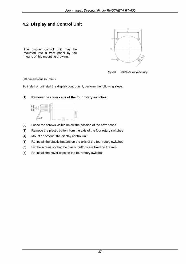
User manual Direction Finder RHOTHETA RT-600
- 37 -
42 Display and Control Unit
The display control unit may be mounted into a front panel by the means of this mounting drawing
Fig 46) DCU Mounting Drawing
(all dimensions in [mm]) To install or uninstall the display control unit perform the following steps (1) Remove the cover caps of the four rotary switches
(2) Loose the screws visible below the position of the cover caps
(3) Remove the plastic button from the axis of the four rotary switches
(4) Mount dismount the display control unit
(5) Re-install the plastic buttons on the axis of the four rotary switches
(6) Fix the screws so that the plastic buttons are fixed on the axis
(7) Re-install the cover caps on the four rotary switches
User manual Direction Finder RHOTHETA RT-600
- 38 -
43 System Interconnect Wiring Diagram (Also refer to chapter ldquoTechnical Datardquo for details)
Fig 47) System Interconnect Wiring Diagram
6-pol Amphenol plug femalePTG06SE10-6S(SQ)
max length of cable 20 m 9-pol Sub-D plug (femalemale)
User manual Direction Finder RHOTHETA RT-600
- 39 -
5 Technical Data
51 Electric features
Method of bearing Doppler-principle (3 kHz rotational frequency right left rotation)
Bearing accuracy1 plusmn 5deg RMS
Internal resolution 1deg
Bearing Sensitivity VHF AirEmergency le 25 μVm (typical)
VHF Marine le 25 μVm (typical)
UHF Emergency and ETS le 4 μVm (typical)
COSPAS-SARSAT le 4 μVm (typical)
LoJack Decoding (50 Message Error Rate) and bearing le 5 μVm (typical)
Frequency stability plusmn 20 ppm (Δff = plusmn210-6)
Reception frequencies
SAR version (Standard)
Frequency Options
VHF Emergency Band 118000 to 124000 MHz (833 kHz steps AM)
VHF Marine Band 154000 to 163000 MHz ( 500 kHz steps FM) (channel 16 selectable via channel no)
UHF Emergency Band 240000 to 246000 MHz (2500 kHz steps AM)
UHF FM Band 406100 to 410000 MHz ( 500 kHz steps FM)
COSPAS-SARSAT 400000 to 406092 MHz Including 406022 to 406076 MHz (Channel A S)
F1 VHF Air Band 118000 to 136992 MHz
F2 extended VHF Marine Band 137000 to 224995 MHz
F3 extended UHF Air Band 225000 to 399975 MHz
F4 additional UHF FM Band 406100 to 470000 MHz
Reception frequencies
LAW Enforcement version
Frequency Options
VHF Emergency Band 118000 to 124000 MHz (833 kHz steps AM)
VHF Marine Band 154000 to 163000 MHz (500 kHz steps FM) (channel 16 selectable via channel no)
LoJack 164000 to 174000 MHz (125 kHz steps FM)
ETS 216000 to 220000 MHz (10125 kHz AM)
COSPAS-SARSAT 400000 to 406092 MHz Including 406022 to 406076 MHz (Channel A S)
F1VHF Air Band 118000 to 136992 MHz
F2 extended VHF Marine Band 137000 to 163000 MHz
COSPAS-SARSAT fast scan mode
Full automatic detection of any active COSPAS-SARSAT channel A to S within 400 ms
COSPAS-SARSAT decoding
Reception and decoding of COSPAS-SARSAT data signal (112 or 144 bit) specified according to COSPAS-SARSAT
LoJack decoding Selectable LoJack ID display and selective active filtering
Special scanning modes
complete maritime ship band scanning within 3 s (channel 01 hellip 88 also frequencies between 2 channels are included)
1With undisturbed wave field and sufficient field strength Measuring by changing the angle of incidence with the antenna rotating on a revolving table in order to eliminate environmental influences on the results No modulation
User manual Direction Finder RHOTHETA RT-600
- 40 -
Bearable modulation A3E F3E A3X (ELT-modulation) F1D G2D COSPAS-SARSAT Bearing largely independent of modulation
Polarization Vertical
Polarization error 5deg at 60deg field vector rotation
Garbling cone Ca 30deg to the vertical
Time of response2 50 ms (with sufficient reception field strength)
LC-graphic display 128 x 64 pixels supertwist transflective extended range of temperature dark-blue display on yellow-green background background light Freely adjustable (exponential) dimming of brightness
NVG cockpit design Fully compatible NVIS Green B display Control Unit optional
Operating voltage 275 V nominal 12 V to 35 V DC
Current consumption LCD-background light Off max 500 mA (12 V DC) max 250 mA (24 V DC)
LCD-background light 100 max 750 mA (12 V DC) max 350 mA (24 V DC)
LCD-background light 100 max 900 mA (12 V DC) with NVG Option max 400 mA (24 V DC)
Audio out For external speaker approx 2 W (4 Ω)
Serial data interface Serial interface RS-232 (9600 baud 8 data bits 1 stop bit no parity)
2Very weak signals can considerably increase the time of response
User manual Direction Finder RHOTHETA RT-600
- 41 -
52 Interface External connections (optional at Sub-D 9-pol Male connector)
Dimming
Pin 8
external voltage input for variable dimming of legends
(optional)
Analog input signal for variable control of the legends illumination Input voltage range is freely adjustable in the range of 15 hellip 28 V in the setup menu Refer to chapter ldquoSetup Pagerdquo Default setting 8 hellip28 V (8 V = Off 28 V = max dimming for legends)
Input Impedance gt 50 k
Pin 6 night status line for LCD
dimming (optional)
Low-active (as example switch to ground) At input voltage lt 25 VDC the LCD dimming operates in nightNVG mode Maximum brightness ca 4 of daydefault mode brightness
Input Impedance gt 50 k
Pin 4 NVG status line for LCD
dimming (optional)
Low-active (as example switch to ground) At input voltage lt 25 VDC the LCD dimming operates in nightNVG mode Maximum brightness ca 4 of daydefault mode brightness
Input Impedance gt 50 k
AudioLF
Pin 7 Audio output signal
AC coupled voltage source with very low inner resistance Maximum output voltage ca 8 VPP = 283V RMS at maximum Volume Maximum output power ca 2 W with 4 speaker
If a headphone is connected ([32hellip600] 100mW) we recommend using a resistor (18 025 W) between audio output and headphone to prevent damage of the headphone
Serial interface RS232 (9600 baud 8 data bits 1 stop bit no parity)
Pin 3 TXD Serial output (ca plusmn10 V)
Pin 2 RXD Serial input (ca plusmn10 V)
User manual Direction Finder RHOTHETA RT-600
- 42 -
53 Mechanical features
Temperature range
Display Control Unit permissible operating temperature3 -20 degC +60 degC permissible storage temperature -30 degC +80 degC
Antenna Unit permissible operating temperature3 -40 degC +60 degC permissible storage temperature -55 degC +80 degC
Protective system Antenna Unit IP 67
Weights Display Control Unit 250 g Antenna Unit 2000 g
Dimensions Display Control Unit 82 mm x 82 mm x 43 mm (width x height x depth) Antenna Unit 270 mm x 185 mm
Fig 48) DCU Mechanical Drawing (all dimensions in [mm])
3 For temperatures lower than ndash10deg C a warm-up period of 15 min should be allowed
User manual Direction Finder RHOTHETA RT-600
- 43 -
Fig 49) AU Mechanical Drawing (all dimensions in [mm])
User manual Direction Finder RHOTHETA RT-600
- 44 -
6 Appendix
61 Frequency Ranges
User manual Direction Finder RHOTHETA RT-600
- 45 -
62 Frequencies of channels on maritime band (only for standard [A] version) Frequency-range of the RT-600 in the maritime band 156000 MHz 162025 MHz
Channel No frequency (ship - station) Frequency (coast - station)
1 156050 MHz 160650 MHz 2 156100 MHz 160700 MHz 3 156150 MHz 160750 MHz 4 156200 MHz 160800 MHz 5 156250 MHz 160850 MHz 6 156300 MHz 160900 MHz 7 156350 MHz 160950 MHz 8 156400 MHz 9 156450 MHz
10 156500 MHz 11 156550 MHz 12 156600 MHz 13 156650 MHz 14 156700 MHz 15 156750 MHz 16 156800 MHz 17 156850 MHz 18 156900 MHz 161500 MHz 19 156950 MHz 161550 MHz 20 157000 MHz 161600 MHz 21 157050 MHz 161650 MHz 22 157100 MHz 161700 MHz 23 157150 MHz 161750 MHz 24 157200 MHz 161800 MHz 25 157250 MHz 161850 MHz 26 157300 MHz 161900 MHz 27 157350 MHz 161950 MHz 28 157400 MHz 162000 MHz 60 156025 MHz 160625 MHz 61 156075 MHz 160675 MHz 62 156125 MHz 160725 MHz 63 156175 MHz 160775 MHz 64 156225 MHz 160825 MHz 65 156275 MHz 160875 MHz 66 156325 MHz 160925 MHz 67 156375 MHz 68 156425 MHz 69 156475 MHz 70 156525 MHz 71 156575 MHz 72 156625 MHz 73 156675 MHz 74 156725 MHz 75 156775 MHz 76 156825 MHz 77 156875 MHz 78 156925 MHz 161525 MHz 79 156975 MHz 161575 MHz 80 157025 MHz 161625 MHz 81 157075 MHz 161675 MHz 82 157125 MHz 161725 MHz 83 157175 MHz 161775 MHz 84 157225 MHz 161825 MHz 85 157275 MHz 161875 MHz 86 157325 MHz 161925 MHz 87 157375 MHz 161975 MHz 88 157425 MHz 162025 MHz
User manual Direction Finder RHOTHETA RT-600
- 46 -
63 Serial interface data protocol (short description)
631 General
Interface parameters RS232 9600 Baud 8 databits 1 stopbit no parity LSB sent first Timing of serial data For accurate use of the serial data (even for the optional serial input commands) the correct timing is mandatory The DCU (Display Control Unit) sends out via the RS-232 Pins (see 43 System Interconnect Wiring Diagram page 38) cyclic and autonomous every approx 250300 ms a binary data stream which contains all relevant DF-bearing information The output data contains one or two blocks of binary data (see next picture with accordingly description) The optional serial input is only used if changes (as example frequency change) are done by additional remote control units
Fig 50) Timing of serial data
Serial standard output
This output data is always available and contains all relevant DF-bearing data For detailed content see page 47
Optional extended serial output
This data contains some additional information like as example CospasSarsat or LoJack decoding and ID data For detailed content see page 50 The data is only available with DCU Software [Rev ge 320] and if this optional data block is configured as ON = enabled (see Setup Edit Page point (10) )
Even to avoid compatibility problems with already existing older remote control software it is possible to disable switch off this additional data block (see Setup Edit Page point (10) )
Optional serial input
Only used for optional commands to control DCU parameters If as example the direction finder frequency is changed remotely there is send to the DCU one time this data block with the new frequency For detailed content see page 52
User manual Direction Finder RHOTHETA RT-600
- 47 -
632 Serial standard output (protocol description)
Specification serial standard output
The binary data stream with a length of 39 bytes starts with a header byte (value = hex 0xA0 as ID for DF Mode) The next bytes contain different values for status bearing information and also service The last byte is used for data stream checksum control Remark This is a binary data protocol So every byte value from 0dec hellip 255dec (0x00 hellip 0xFF) is possible Because of this it is not allowed to realize a start byte detection by the content (0xA0) The idle line detection is recommended for detection the end of message Register of databytes (for details see next page)
byte no
[0] Header = 0xA0 Id for DF Mode
[1] Number = 39 = bytes in the complete message (including header and checksumbyte)
[2] Status (1) HSB [x|x|x|x|x|x|x|x] LSB | | | | | | | --gt (0) Receiving | | | | | | ----gt (1) Squelch controlled by AU (X) | | | | | ------gt (2) Permission RL Calibration | | | | --------gt (3) Line Night | | | ----------gt (4) Line NVG | | ------------gt (5) Dimming External | --------------gt (6) Autosquelch Active ----------------gt (7) 0=Standard Version 1=LE Version
[3] Status (2) HSB [x|x|x|x|x|x|x|x] LSB | ----------------gt (7) 0=Standard 1=extended serial dataprotocol = ONactive
[45] Error (Bits[120])
[6] Actual DCU Page
[7] Volume [0hellip100]
[811] Frequency [Hz]
[12] Active Band
[13] Actual Squelchlevel [0hellip60]
[14] Audio-Line amp_NF_Test Output
[15] (Not used)
[1617] Voltage_DCU ([0hellip335]=[0 hellip 335]V
[1819] Voltage_AU ([0hellip255]=[0 hellip 255]V
[20] Temperature_AU [-68hellip+127]degC
[21] Frequency Offset [-99hellip+99]
[2225] ServiceTest values (mode dependent test values for service only)
26 (Not used reserved)
[27] Level [0hellip100]
[2829] Bearing Averaged [0hellip359]deg relative
[3031] Bearing Live_Min [0hellip359]deg relative
[3233] Bearing Live_Max [0hellip359]deg relative
[34] Test Value PS-RAM Right Rotation[0hellip178] (for service only)
[35] Test Value PS-RAM Left Rotation [0hellip178] (for service only)
[3637] (Not used reserved)
[38] Checksum is the 2rsquos complement of the modulo-256 sum of all bytes without checksum-byte [0n-1]
User manual Direction Finder RHOTHETA RT-600
- 48 -
Detailed Description of important values for practical use
Status byte [2] Receiving Bit 0 of this value (LSB) indicates signal receiving Bit 0 = 0 then no signal is received and so on no bearing is available Bit 0 = 1 then bearing is possible Bit 1 if(1) then Squelch is controlled by AU (active at modes CospasSarsat Decode CospasSarsat Scanning LoJack with Filter=ID only)
Error bytes [4hellip5] 16 bit value each set bit corresponds to the error no (Refer to the chapter Error messages) Example - 0x0000 No error - 0x0800 Bit No 11 Set ( = No AU Error)
Actual DCU Page byte [6] indicates actual operating mode of DCU 0 = Standard bearing page 1 = Frequency memory page 2 = CospasSarsat decoding page 3 = LoJack decoding page (ID edit)
Frequency bytes [8hellip11] 32 bit value actual adjusted frequency [Hz] Example - 0x073DF160 1215000000 121500 MHz
Active Band Standard Version [A] 0=VHF Airband 1=VHF Marineband sea 2=VHF Marineband coast 3=UHV Airband 4=CospasSarsat LE Version [L] 0=VHF Airband 1=LoJack 2=Lifesaver 3=ETS 4=CospasSarsat
Actual Squelchlevel byte [13] Range [0hellip60] without signal the actual squelchlevel should always be adjusted a little bit over the noise level (Refer to the chapter Squelch operation)
Level byte [27] Range [099] actual receiving level (without signal this value is equal to the noise level) If a signal is received then this value corresponds to the signal strength of this signal
Relative Bearing averaged byte [2829] 16 bit value Range [0hellip359 0xFFFF] if the value = 0xFFFF then no valid bearing is available otherwise this value contains the actual averaged bearing information in Deg [0deg359deg] Example - 0X0114 276deg bearing (= left side oriented to heading)
Bearing Live MinMax byte[3031] amp [3233] - 16 bit values Range [0hellip359 0xFFFF] Only for signal quality or additional information ndash NOT recommended for bearing indication The relative live bearing field contains the maxmin bearing in degrees without averaging The relative live bearing reacts faster than the normal relative bearing but it has not the precision of the averaged bearing The MinMax Bearing Values are calculated within a time period of approx 250 ms If they are very close together (for example ldquo124rdquo and ldquo128rdquo degrees) then the signal quality is quite good A wide span of the minmax values (for example ldquo97rdquo and ldquo162rdquo) shows very noisy but nevertheless bearable signal quality
User manual Direction Finder RHOTHETA RT-600
- 49 -
633 DCU Info output (protocol description)
Specification DCU Info output
Remark This protocol is only available while the SetupEdit page is activated at the DCU
byte no
[0] Header = 0xAF Id for DCU Info Mode
[1] Number = 39 = bytes in the complete message (including header and checksumbyte)
[2]
(see standard output) [3]
[45]
[621] Info String of 15 byteschars the string contains Information about Unit Variant Software Version and Serial No
Example Byte [318] =
|--AU ID---||Var-||---Software Version---| |-------------- Serial No---------------| [0x44][0x55][0x41][0x33][0x2E][0x33][0x30][0x3A][0x20][0x20][0x30][0x31][0x32][0x33][0x34][0x00] rsquoDrsquo rsquoUrsquo rsquoArsquo rsquo3rsquo rsquorsquo rsquo3rsquo rsquo0rsquo rsquorsquo rsquo rsquo rsquo rsquo rsquo0rsquo rsquo1rsquo rsquo2rsquo rsquo3rsquo rsquo4rsquo rsquoENDrsquo | | | | __________________ | | ________________________ | n n n | | n n n n n | (Software Version) | | (Serial No) | gt rsquoArsquo = Standard Variant gt rsquoLrsquo = Law Enforcement Variant
User manual Direction Finder RHOTHETA RT-600
- 50 -
634 Optional extended serial output (protocol description)
The data content depends on the actual mode of the direction finder To get special data the direction finder has first to be switched to the equivalent mode
COSPAS-SARSAT Decoding data
This data is only available and valid if Display Control Unit with actual software Rev ge 320 (see Power-On procedure page 10) Configuration of Extended serial = ON (see Setup Edit Page point (10) ) Direction Finder COSPAS-SARSAT decoding mode is activated by selecting the corresponding page
(see COSPAS-SARSAT Decode Window page 20 and page 21) and so on Header (byte 0 of data) = 0x91
A valid COSPAS-SARSAT decoding data protocol is always marked by the first data byte (header = 0x91) Always after receiving and decoding of a valid COSPAS-SARSAT pulse the complete data protocol with 33 bytes is send out one time
Byte No
[0] Header = 0x91 (Identification for CPSarsat decoding mode)
[1] Number of bytes - 7 if no decoded pulse is available - 33 if new pulse was received and is available
[2] Error
[3] Bit[0] - 0 =gt No new 406 MSG (decoded data) available - 1 =gt New valid 406 MSG available (Sync amp Frame Ok) Check Error Status for Bit-Errors
Bit[61] AutoSquelch Level valid range [060] ( decimal)
Bit[7] = 1 Squelch controlled by AU
[4] Signallevel of received signal valid range [099] ( decimal)
[5] Voltage of Antenna Unit Power Supply input valid range [80255] (decimal = 80 255 V DC)
[6] Temperature inside Antenna Unit valid range [-50+100] (degC signed byte value)
The following databytes are only available if a correct CPSarsat puls gets received and decoded with correct checksum
[724] 18 x Databytes complete orginal CPSarsat 406 decoded message (144 bit)
Databyte Nr [ Byte 7 ] [ Byte 8 ] [Byte9 Byte24] 406 MSG Bit Nr [1 2 3 4 5 6 7 8] [9 10 11 12 13 14 15 16] [17 144]
[25] SN-Flag valid values 0x53=rsquoSrsquo 0x4E=rsquoNrsquo 0x2D=rsquo-rsquo if no GPS data available
GPS-Position Latitude
[26] Deg valid values [090] (decimal Deg) 0xFF if no GPS data available
[27] Min valid values [059] (decimal Deg) 0xFF if no GPS data available
[28] Sec valid values [059] (decimal Deg) 0xFF if no GPS data available
[29] WE-Flag valid values 0x57=rsquoWrsquo 0x45=rsquoErsquo 0x2D=rsquo-rsquo if no GPS data available
GPS-Position Longitude
[30] Deg valid values [0180] (decimal Deg) 0xFF if no GPS data available
[31] Min valid values [059] (decimal Deg) 0xFF if no GPS data available
[32] Sec valid values [059] (decimal Deg) 0xFF if no GPS data available
User manual Direction Finder RHOTHETA RT-600
- 51 -
LoJack ID data
This data is only available and valid if Display Control Unit with actual software Rev ge 320 (see Power-On procedure page 10) Direction Finder of variant [L] Law Enforcement Configuration of Extended serial = ON (see Setup Edit Page point (10) ) Direction Finder is working with active LoJack gtID Filterlt Header (byte 0 of data) = 0x93 or 0x94
Valid LoJack ID decoding data is always marked by the first data byte (header = 0x93 or 0x94)
Byte No
[0] Header = 0x93 LoJack ID editing sub-page is selected Filter = VLU all valid and received LoJack pulses are indicated = 0x94 Lojack Decode amp DF Mode with active Filter = ID
[1] Number of bytes in the complete data stream - decimal 26 = default value
[2] Nonrelevant
[3] Bit[0] Receiving OnOff - 0 =gt No Receiving no bearing - 1 =gt new LoJack pulse received
[412] Nonrelevant
[1317] Lojack ID
Replay Code 5 x ASCII Chars ldquoNo BIOZrdquo set
Example ASCII = ldquo000R1rdquo
18 Receiver Level Out Max [099]
19
LoJack Decoder Status [07] - 0 Off - 1 Wait for Preamble - 2 Preamble Ok - 3 FlagPattern Ok - 4 Data BitError gt 1 - 5 Data Ok (No VLU) - 6 VLU Ok - 7 ID Ok (Filter=IDONLY)
[2025] Nonrelevant
Remark Only if byte no [3] bit [0] gets ldquo1rdquo (Receiving On) then an active LoJack pulse is received and so on the corresponding LoJack ID valid otherwise the LoJack ID only shows the actual adjusted LoJack Filter ID of the direction finder
User manual Direction Finder RHOTHETA RT-600
- 52 -
635 Optional serial input (protocol description)
Specification serial input (optional)
The serial input is normally used for service and maintenance only Nevertheless it is possible via this interface to remote control the actual frequency and the squelchlevel of the DF system If a valid data stream is send to the DF then the actual frequency selection at the DCU is switched to Block2 AUX0 At this memory channel the new frequency is stored and used automatically (Refer to the chapter Frequency Selection Page) If the frequency is changed (by one valid data stream) no more serial input is necessary The actual frequency can be changed again at any time by manual operation at the DCU The timing of serial input (if used) is strictly fixed The optional serial input has to take place directly after a complete serial output (max 50 ms delay time) If a new changed frequency is commanded to the DCU via this serial input interface it can take up to 1 sec of time until this new frequency is ready for operationbearing It is strictly not recommended to use the frequency remote control for any scan mode The frequency control has to be used for static frequency change only Register of databytes
byte no
[0] Header 0xC0
[1] Number of bytes in the complete message (including header and checksumbyte)
[23] (not used for normal operation any byte values allowed)
[4] Volume [0100]
[58] Frequency [Hz] (frequency is rounded to the according grid automatically)
Valid Range for Standard Version Valid Range for LE Version
118000000 hellip 123000000 [Hz] 8333 kHz 118000000 hellip 123000000 [Hz] 8333 kHz
156050000 hellip 162025000 [Hz] 5000 kHz 164000000 hellip 174000000 [Hz] 8333 kHz
201000000 hellip 215995000 [Hz] 5000 kHz
240000000 hellip 246000000 [Hz] 8333 kHz 216000000 hellip 218995000 [Hz] 12500 kHz219000000 hellip 220000000 [Hz] 10000 kHz
400000000 hellip 410000000 [Hz] 8333 kHz 400000000 hellip 410000000 [Hz] 8333 kHz
[9] Squelchlevel Manual = [0hellip60] Autosql= [ -1] Warning use only for pulsed signals (as example CpSarsat LoJack)
[10] (not used for normal operation any byte values allowed)
[11] Internal Dimming [0100]
[12] Checksum is the 2rsquos complement of the modulo-256 sum of all bytes without checksum-byte [0n-1]
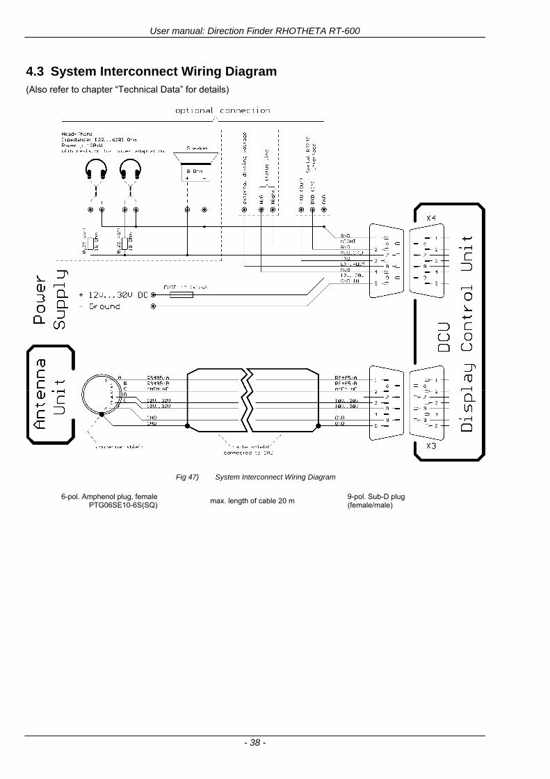
User manual Direction Finder RHOTHETA RT-600
- 38 -
43 System Interconnect Wiring Diagram (Also refer to chapter ldquoTechnical Datardquo for details)
Fig 47) System Interconnect Wiring Diagram
6-pol Amphenol plug femalePTG06SE10-6S(SQ)
max length of cable 20 m 9-pol Sub-D plug (femalemale)
User manual Direction Finder RHOTHETA RT-600
- 39 -
5 Technical Data
51 Electric features
Method of bearing Doppler-principle (3 kHz rotational frequency right left rotation)
Bearing accuracy1 plusmn 5deg RMS
Internal resolution 1deg
Bearing Sensitivity VHF AirEmergency le 25 μVm (typical)
VHF Marine le 25 μVm (typical)
UHF Emergency and ETS le 4 μVm (typical)
COSPAS-SARSAT le 4 μVm (typical)
LoJack Decoding (50 Message Error Rate) and bearing le 5 μVm (typical)
Frequency stability plusmn 20 ppm (Δff = plusmn210-6)
Reception frequencies
SAR version (Standard)
Frequency Options
VHF Emergency Band 118000 to 124000 MHz (833 kHz steps AM)
VHF Marine Band 154000 to 163000 MHz ( 500 kHz steps FM) (channel 16 selectable via channel no)
UHF Emergency Band 240000 to 246000 MHz (2500 kHz steps AM)
UHF FM Band 406100 to 410000 MHz ( 500 kHz steps FM)
COSPAS-SARSAT 400000 to 406092 MHz Including 406022 to 406076 MHz (Channel A S)
F1 VHF Air Band 118000 to 136992 MHz
F2 extended VHF Marine Band 137000 to 224995 MHz
F3 extended UHF Air Band 225000 to 399975 MHz
F4 additional UHF FM Band 406100 to 470000 MHz
Reception frequencies
LAW Enforcement version
Frequency Options
VHF Emergency Band 118000 to 124000 MHz (833 kHz steps AM)
VHF Marine Band 154000 to 163000 MHz (500 kHz steps FM) (channel 16 selectable via channel no)
LoJack 164000 to 174000 MHz (125 kHz steps FM)
ETS 216000 to 220000 MHz (10125 kHz AM)
COSPAS-SARSAT 400000 to 406092 MHz Including 406022 to 406076 MHz (Channel A S)
F1VHF Air Band 118000 to 136992 MHz
F2 extended VHF Marine Band 137000 to 163000 MHz
COSPAS-SARSAT fast scan mode
Full automatic detection of any active COSPAS-SARSAT channel A to S within 400 ms
COSPAS-SARSAT decoding
Reception and decoding of COSPAS-SARSAT data signal (112 or 144 bit) specified according to COSPAS-SARSAT
LoJack decoding Selectable LoJack ID display and selective active filtering
Special scanning modes
complete maritime ship band scanning within 3 s (channel 01 hellip 88 also frequencies between 2 channels are included)
1With undisturbed wave field and sufficient field strength Measuring by changing the angle of incidence with the antenna rotating on a revolving table in order to eliminate environmental influences on the results No modulation
User manual Direction Finder RHOTHETA RT-600
- 40 -
Bearable modulation A3E F3E A3X (ELT-modulation) F1D G2D COSPAS-SARSAT Bearing largely independent of modulation
Polarization Vertical
Polarization error 5deg at 60deg field vector rotation
Garbling cone Ca 30deg to the vertical
Time of response2 50 ms (with sufficient reception field strength)
LC-graphic display 128 x 64 pixels supertwist transflective extended range of temperature dark-blue display on yellow-green background background light Freely adjustable (exponential) dimming of brightness
NVG cockpit design Fully compatible NVIS Green B display Control Unit optional
Operating voltage 275 V nominal 12 V to 35 V DC
Current consumption LCD-background light Off max 500 mA (12 V DC) max 250 mA (24 V DC)
LCD-background light 100 max 750 mA (12 V DC) max 350 mA (24 V DC)
LCD-background light 100 max 900 mA (12 V DC) with NVG Option max 400 mA (24 V DC)
Audio out For external speaker approx 2 W (4 Ω)
Serial data interface Serial interface RS-232 (9600 baud 8 data bits 1 stop bit no parity)
2Very weak signals can considerably increase the time of response
User manual Direction Finder RHOTHETA RT-600
- 41 -
52 Interface External connections (optional at Sub-D 9-pol Male connector)
Dimming
Pin 8
external voltage input for variable dimming of legends
(optional)
Analog input signal for variable control of the legends illumination Input voltage range is freely adjustable in the range of 15 hellip 28 V in the setup menu Refer to chapter ldquoSetup Pagerdquo Default setting 8 hellip28 V (8 V = Off 28 V = max dimming for legends)
Input Impedance gt 50 k
Pin 6 night status line for LCD
dimming (optional)
Low-active (as example switch to ground) At input voltage lt 25 VDC the LCD dimming operates in nightNVG mode Maximum brightness ca 4 of daydefault mode brightness
Input Impedance gt 50 k
Pin 4 NVG status line for LCD
dimming (optional)
Low-active (as example switch to ground) At input voltage lt 25 VDC the LCD dimming operates in nightNVG mode Maximum brightness ca 4 of daydefault mode brightness
Input Impedance gt 50 k
AudioLF
Pin 7 Audio output signal
AC coupled voltage source with very low inner resistance Maximum output voltage ca 8 VPP = 283V RMS at maximum Volume Maximum output power ca 2 W with 4 speaker
If a headphone is connected ([32hellip600] 100mW) we recommend using a resistor (18 025 W) between audio output and headphone to prevent damage of the headphone
Serial interface RS232 (9600 baud 8 data bits 1 stop bit no parity)
Pin 3 TXD Serial output (ca plusmn10 V)
Pin 2 RXD Serial input (ca plusmn10 V)
User manual Direction Finder RHOTHETA RT-600
- 42 -
53 Mechanical features
Temperature range
Display Control Unit permissible operating temperature3 -20 degC +60 degC permissible storage temperature -30 degC +80 degC
Antenna Unit permissible operating temperature3 -40 degC +60 degC permissible storage temperature -55 degC +80 degC
Protective system Antenna Unit IP 67
Weights Display Control Unit 250 g Antenna Unit 2000 g
Dimensions Display Control Unit 82 mm x 82 mm x 43 mm (width x height x depth) Antenna Unit 270 mm x 185 mm
Fig 48) DCU Mechanical Drawing (all dimensions in [mm])
3 For temperatures lower than ndash10deg C a warm-up period of 15 min should be allowed
User manual Direction Finder RHOTHETA RT-600
- 43 -
Fig 49) AU Mechanical Drawing (all dimensions in [mm])
User manual Direction Finder RHOTHETA RT-600
- 44 -
6 Appendix
61 Frequency Ranges
User manual Direction Finder RHOTHETA RT-600
- 45 -
62 Frequencies of channels on maritime band (only for standard [A] version) Frequency-range of the RT-600 in the maritime band 156000 MHz 162025 MHz
Channel No frequency (ship - station) Frequency (coast - station)
1 156050 MHz 160650 MHz 2 156100 MHz 160700 MHz 3 156150 MHz 160750 MHz 4 156200 MHz 160800 MHz 5 156250 MHz 160850 MHz 6 156300 MHz 160900 MHz 7 156350 MHz 160950 MHz 8 156400 MHz 9 156450 MHz
10 156500 MHz 11 156550 MHz 12 156600 MHz 13 156650 MHz 14 156700 MHz 15 156750 MHz 16 156800 MHz 17 156850 MHz 18 156900 MHz 161500 MHz 19 156950 MHz 161550 MHz 20 157000 MHz 161600 MHz 21 157050 MHz 161650 MHz 22 157100 MHz 161700 MHz 23 157150 MHz 161750 MHz 24 157200 MHz 161800 MHz 25 157250 MHz 161850 MHz 26 157300 MHz 161900 MHz 27 157350 MHz 161950 MHz 28 157400 MHz 162000 MHz 60 156025 MHz 160625 MHz 61 156075 MHz 160675 MHz 62 156125 MHz 160725 MHz 63 156175 MHz 160775 MHz 64 156225 MHz 160825 MHz 65 156275 MHz 160875 MHz 66 156325 MHz 160925 MHz 67 156375 MHz 68 156425 MHz 69 156475 MHz 70 156525 MHz 71 156575 MHz 72 156625 MHz 73 156675 MHz 74 156725 MHz 75 156775 MHz 76 156825 MHz 77 156875 MHz 78 156925 MHz 161525 MHz 79 156975 MHz 161575 MHz 80 157025 MHz 161625 MHz 81 157075 MHz 161675 MHz 82 157125 MHz 161725 MHz 83 157175 MHz 161775 MHz 84 157225 MHz 161825 MHz 85 157275 MHz 161875 MHz 86 157325 MHz 161925 MHz 87 157375 MHz 161975 MHz 88 157425 MHz 162025 MHz
User manual Direction Finder RHOTHETA RT-600
- 46 -
63 Serial interface data protocol (short description)
631 General
Interface parameters RS232 9600 Baud 8 databits 1 stopbit no parity LSB sent first Timing of serial data For accurate use of the serial data (even for the optional serial input commands) the correct timing is mandatory The DCU (Display Control Unit) sends out via the RS-232 Pins (see 43 System Interconnect Wiring Diagram page 38) cyclic and autonomous every approx 250300 ms a binary data stream which contains all relevant DF-bearing information The output data contains one or two blocks of binary data (see next picture with accordingly description) The optional serial input is only used if changes (as example frequency change) are done by additional remote control units
Fig 50) Timing of serial data
Serial standard output
This output data is always available and contains all relevant DF-bearing data For detailed content see page 47
Optional extended serial output
This data contains some additional information like as example CospasSarsat or LoJack decoding and ID data For detailed content see page 50 The data is only available with DCU Software [Rev ge 320] and if this optional data block is configured as ON = enabled (see Setup Edit Page point (10) )
Even to avoid compatibility problems with already existing older remote control software it is possible to disable switch off this additional data block (see Setup Edit Page point (10) )
Optional serial input
Only used for optional commands to control DCU parameters If as example the direction finder frequency is changed remotely there is send to the DCU one time this data block with the new frequency For detailed content see page 52
User manual Direction Finder RHOTHETA RT-600
- 47 -
632 Serial standard output (protocol description)
Specification serial standard output
The binary data stream with a length of 39 bytes starts with a header byte (value = hex 0xA0 as ID for DF Mode) The next bytes contain different values for status bearing information and also service The last byte is used for data stream checksum control Remark This is a binary data protocol So every byte value from 0dec hellip 255dec (0x00 hellip 0xFF) is possible Because of this it is not allowed to realize a start byte detection by the content (0xA0) The idle line detection is recommended for detection the end of message Register of databytes (for details see next page)
byte no
[0] Header = 0xA0 Id for DF Mode
[1] Number = 39 = bytes in the complete message (including header and checksumbyte)
[2] Status (1) HSB [x|x|x|x|x|x|x|x] LSB | | | | | | | --gt (0) Receiving | | | | | | ----gt (1) Squelch controlled by AU (X) | | | | | ------gt (2) Permission RL Calibration | | | | --------gt (3) Line Night | | | ----------gt (4) Line NVG | | ------------gt (5) Dimming External | --------------gt (6) Autosquelch Active ----------------gt (7) 0=Standard Version 1=LE Version
[3] Status (2) HSB [x|x|x|x|x|x|x|x] LSB | ----------------gt (7) 0=Standard 1=extended serial dataprotocol = ONactive
[45] Error (Bits[120])
[6] Actual DCU Page
[7] Volume [0hellip100]
[811] Frequency [Hz]
[12] Active Band
[13] Actual Squelchlevel [0hellip60]
[14] Audio-Line amp_NF_Test Output
[15] (Not used)
[1617] Voltage_DCU ([0hellip335]=[0 hellip 335]V
[1819] Voltage_AU ([0hellip255]=[0 hellip 255]V
[20] Temperature_AU [-68hellip+127]degC
[21] Frequency Offset [-99hellip+99]
[2225] ServiceTest values (mode dependent test values for service only)
26 (Not used reserved)
[27] Level [0hellip100]
[2829] Bearing Averaged [0hellip359]deg relative
[3031] Bearing Live_Min [0hellip359]deg relative
[3233] Bearing Live_Max [0hellip359]deg relative
[34] Test Value PS-RAM Right Rotation[0hellip178] (for service only)
[35] Test Value PS-RAM Left Rotation [0hellip178] (for service only)
[3637] (Not used reserved)
[38] Checksum is the 2rsquos complement of the modulo-256 sum of all bytes without checksum-byte [0n-1]
User manual Direction Finder RHOTHETA RT-600
- 48 -
Detailed Description of important values for practical use
Status byte [2] Receiving Bit 0 of this value (LSB) indicates signal receiving Bit 0 = 0 then no signal is received and so on no bearing is available Bit 0 = 1 then bearing is possible Bit 1 if(1) then Squelch is controlled by AU (active at modes CospasSarsat Decode CospasSarsat Scanning LoJack with Filter=ID only)
Error bytes [4hellip5] 16 bit value each set bit corresponds to the error no (Refer to the chapter Error messages) Example - 0x0000 No error - 0x0800 Bit No 11 Set ( = No AU Error)
Actual DCU Page byte [6] indicates actual operating mode of DCU 0 = Standard bearing page 1 = Frequency memory page 2 = CospasSarsat decoding page 3 = LoJack decoding page (ID edit)
Frequency bytes [8hellip11] 32 bit value actual adjusted frequency [Hz] Example - 0x073DF160 1215000000 121500 MHz
Active Band Standard Version [A] 0=VHF Airband 1=VHF Marineband sea 2=VHF Marineband coast 3=UHV Airband 4=CospasSarsat LE Version [L] 0=VHF Airband 1=LoJack 2=Lifesaver 3=ETS 4=CospasSarsat
Actual Squelchlevel byte [13] Range [0hellip60] without signal the actual squelchlevel should always be adjusted a little bit over the noise level (Refer to the chapter Squelch operation)
Level byte [27] Range [099] actual receiving level (without signal this value is equal to the noise level) If a signal is received then this value corresponds to the signal strength of this signal
Relative Bearing averaged byte [2829] 16 bit value Range [0hellip359 0xFFFF] if the value = 0xFFFF then no valid bearing is available otherwise this value contains the actual averaged bearing information in Deg [0deg359deg] Example - 0X0114 276deg bearing (= left side oriented to heading)
Bearing Live MinMax byte[3031] amp [3233] - 16 bit values Range [0hellip359 0xFFFF] Only for signal quality or additional information ndash NOT recommended for bearing indication The relative live bearing field contains the maxmin bearing in degrees without averaging The relative live bearing reacts faster than the normal relative bearing but it has not the precision of the averaged bearing The MinMax Bearing Values are calculated within a time period of approx 250 ms If they are very close together (for example ldquo124rdquo and ldquo128rdquo degrees) then the signal quality is quite good A wide span of the minmax values (for example ldquo97rdquo and ldquo162rdquo) shows very noisy but nevertheless bearable signal quality
User manual Direction Finder RHOTHETA RT-600
- 49 -
633 DCU Info output (protocol description)
Specification DCU Info output
Remark This protocol is only available while the SetupEdit page is activated at the DCU
byte no
[0] Header = 0xAF Id for DCU Info Mode
[1] Number = 39 = bytes in the complete message (including header and checksumbyte)
[2]
(see standard output) [3]
[45]
[621] Info String of 15 byteschars the string contains Information about Unit Variant Software Version and Serial No
Example Byte [318] =
|--AU ID---||Var-||---Software Version---| |-------------- Serial No---------------| [0x44][0x55][0x41][0x33][0x2E][0x33][0x30][0x3A][0x20][0x20][0x30][0x31][0x32][0x33][0x34][0x00] rsquoDrsquo rsquoUrsquo rsquoArsquo rsquo3rsquo rsquorsquo rsquo3rsquo rsquo0rsquo rsquorsquo rsquo rsquo rsquo rsquo rsquo0rsquo rsquo1rsquo rsquo2rsquo rsquo3rsquo rsquo4rsquo rsquoENDrsquo | | | | __________________ | | ________________________ | n n n | | n n n n n | (Software Version) | | (Serial No) | gt rsquoArsquo = Standard Variant gt rsquoLrsquo = Law Enforcement Variant
User manual Direction Finder RHOTHETA RT-600
- 50 -
634 Optional extended serial output (protocol description)
The data content depends on the actual mode of the direction finder To get special data the direction finder has first to be switched to the equivalent mode
COSPAS-SARSAT Decoding data
This data is only available and valid if Display Control Unit with actual software Rev ge 320 (see Power-On procedure page 10) Configuration of Extended serial = ON (see Setup Edit Page point (10) ) Direction Finder COSPAS-SARSAT decoding mode is activated by selecting the corresponding page
(see COSPAS-SARSAT Decode Window page 20 and page 21) and so on Header (byte 0 of data) = 0x91
A valid COSPAS-SARSAT decoding data protocol is always marked by the first data byte (header = 0x91) Always after receiving and decoding of a valid COSPAS-SARSAT pulse the complete data protocol with 33 bytes is send out one time
Byte No
[0] Header = 0x91 (Identification for CPSarsat decoding mode)
[1] Number of bytes - 7 if no decoded pulse is available - 33 if new pulse was received and is available
[2] Error
[3] Bit[0] - 0 =gt No new 406 MSG (decoded data) available - 1 =gt New valid 406 MSG available (Sync amp Frame Ok) Check Error Status for Bit-Errors
Bit[61] AutoSquelch Level valid range [060] ( decimal)
Bit[7] = 1 Squelch controlled by AU
[4] Signallevel of received signal valid range [099] ( decimal)
[5] Voltage of Antenna Unit Power Supply input valid range [80255] (decimal = 80 255 V DC)
[6] Temperature inside Antenna Unit valid range [-50+100] (degC signed byte value)
The following databytes are only available if a correct CPSarsat puls gets received and decoded with correct checksum
[724] 18 x Databytes complete orginal CPSarsat 406 decoded message (144 bit)
Databyte Nr [ Byte 7 ] [ Byte 8 ] [Byte9 Byte24] 406 MSG Bit Nr [1 2 3 4 5 6 7 8] [9 10 11 12 13 14 15 16] [17 144]
[25] SN-Flag valid values 0x53=rsquoSrsquo 0x4E=rsquoNrsquo 0x2D=rsquo-rsquo if no GPS data available
GPS-Position Latitude
[26] Deg valid values [090] (decimal Deg) 0xFF if no GPS data available
[27] Min valid values [059] (decimal Deg) 0xFF if no GPS data available
[28] Sec valid values [059] (decimal Deg) 0xFF if no GPS data available
[29] WE-Flag valid values 0x57=rsquoWrsquo 0x45=rsquoErsquo 0x2D=rsquo-rsquo if no GPS data available
GPS-Position Longitude
[30] Deg valid values [0180] (decimal Deg) 0xFF if no GPS data available
[31] Min valid values [059] (decimal Deg) 0xFF if no GPS data available
[32] Sec valid values [059] (decimal Deg) 0xFF if no GPS data available
User manual Direction Finder RHOTHETA RT-600
- 51 -
LoJack ID data
This data is only available and valid if Display Control Unit with actual software Rev ge 320 (see Power-On procedure page 10) Direction Finder of variant [L] Law Enforcement Configuration of Extended serial = ON (see Setup Edit Page point (10) ) Direction Finder is working with active LoJack gtID Filterlt Header (byte 0 of data) = 0x93 or 0x94
Valid LoJack ID decoding data is always marked by the first data byte (header = 0x93 or 0x94)
Byte No
[0] Header = 0x93 LoJack ID editing sub-page is selected Filter = VLU all valid and received LoJack pulses are indicated = 0x94 Lojack Decode amp DF Mode with active Filter = ID
[1] Number of bytes in the complete data stream - decimal 26 = default value
[2] Nonrelevant
[3] Bit[0] Receiving OnOff - 0 =gt No Receiving no bearing - 1 =gt new LoJack pulse received
[412] Nonrelevant
[1317] Lojack ID
Replay Code 5 x ASCII Chars ldquoNo BIOZrdquo set
Example ASCII = ldquo000R1rdquo
18 Receiver Level Out Max [099]
19
LoJack Decoder Status [07] - 0 Off - 1 Wait for Preamble - 2 Preamble Ok - 3 FlagPattern Ok - 4 Data BitError gt 1 - 5 Data Ok (No VLU) - 6 VLU Ok - 7 ID Ok (Filter=IDONLY)
[2025] Nonrelevant
Remark Only if byte no [3] bit [0] gets ldquo1rdquo (Receiving On) then an active LoJack pulse is received and so on the corresponding LoJack ID valid otherwise the LoJack ID only shows the actual adjusted LoJack Filter ID of the direction finder
User manual Direction Finder RHOTHETA RT-600
- 52 -
635 Optional serial input (protocol description)
Specification serial input (optional)
The serial input is normally used for service and maintenance only Nevertheless it is possible via this interface to remote control the actual frequency and the squelchlevel of the DF system If a valid data stream is send to the DF then the actual frequency selection at the DCU is switched to Block2 AUX0 At this memory channel the new frequency is stored and used automatically (Refer to the chapter Frequency Selection Page) If the frequency is changed (by one valid data stream) no more serial input is necessary The actual frequency can be changed again at any time by manual operation at the DCU The timing of serial input (if used) is strictly fixed The optional serial input has to take place directly after a complete serial output (max 50 ms delay time) If a new changed frequency is commanded to the DCU via this serial input interface it can take up to 1 sec of time until this new frequency is ready for operationbearing It is strictly not recommended to use the frequency remote control for any scan mode The frequency control has to be used for static frequency change only Register of databytes
byte no
[0] Header 0xC0
[1] Number of bytes in the complete message (including header and checksumbyte)
[23] (not used for normal operation any byte values allowed)
[4] Volume [0100]
[58] Frequency [Hz] (frequency is rounded to the according grid automatically)
Valid Range for Standard Version Valid Range for LE Version
118000000 hellip 123000000 [Hz] 8333 kHz 118000000 hellip 123000000 [Hz] 8333 kHz
156050000 hellip 162025000 [Hz] 5000 kHz 164000000 hellip 174000000 [Hz] 8333 kHz
201000000 hellip 215995000 [Hz] 5000 kHz
240000000 hellip 246000000 [Hz] 8333 kHz 216000000 hellip 218995000 [Hz] 12500 kHz219000000 hellip 220000000 [Hz] 10000 kHz
400000000 hellip 410000000 [Hz] 8333 kHz 400000000 hellip 410000000 [Hz] 8333 kHz
[9] Squelchlevel Manual = [0hellip60] Autosql= [ -1] Warning use only for pulsed signals (as example CpSarsat LoJack)
[10] (not used for normal operation any byte values allowed)
[11] Internal Dimming [0100]
[12] Checksum is the 2rsquos complement of the modulo-256 sum of all bytes without checksum-byte [0n-1]
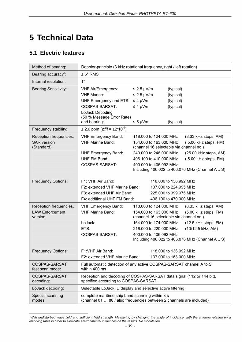
User manual Direction Finder RHOTHETA RT-600
- 39 -
5 Technical Data
51 Electric features
Method of bearing Doppler-principle (3 kHz rotational frequency right left rotation)
Bearing accuracy1 plusmn 5deg RMS
Internal resolution 1deg
Bearing Sensitivity VHF AirEmergency le 25 μVm (typical)
VHF Marine le 25 μVm (typical)
UHF Emergency and ETS le 4 μVm (typical)
COSPAS-SARSAT le 4 μVm (typical)
LoJack Decoding (50 Message Error Rate) and bearing le 5 μVm (typical)
Frequency stability plusmn 20 ppm (Δff = plusmn210-6)
Reception frequencies
SAR version (Standard)
Frequency Options
VHF Emergency Band 118000 to 124000 MHz (833 kHz steps AM)
VHF Marine Band 154000 to 163000 MHz ( 500 kHz steps FM) (channel 16 selectable via channel no)
UHF Emergency Band 240000 to 246000 MHz (2500 kHz steps AM)
UHF FM Band 406100 to 410000 MHz ( 500 kHz steps FM)
COSPAS-SARSAT 400000 to 406092 MHz Including 406022 to 406076 MHz (Channel A S)
F1 VHF Air Band 118000 to 136992 MHz
F2 extended VHF Marine Band 137000 to 224995 MHz
F3 extended UHF Air Band 225000 to 399975 MHz
F4 additional UHF FM Band 406100 to 470000 MHz
Reception frequencies
LAW Enforcement version
Frequency Options
VHF Emergency Band 118000 to 124000 MHz (833 kHz steps AM)
VHF Marine Band 154000 to 163000 MHz (500 kHz steps FM) (channel 16 selectable via channel no)
LoJack 164000 to 174000 MHz (125 kHz steps FM)
ETS 216000 to 220000 MHz (10125 kHz AM)
COSPAS-SARSAT 400000 to 406092 MHz Including 406022 to 406076 MHz (Channel A S)
F1VHF Air Band 118000 to 136992 MHz
F2 extended VHF Marine Band 137000 to 163000 MHz
COSPAS-SARSAT fast scan mode
Full automatic detection of any active COSPAS-SARSAT channel A to S within 400 ms
COSPAS-SARSAT decoding
Reception and decoding of COSPAS-SARSAT data signal (112 or 144 bit) specified according to COSPAS-SARSAT
LoJack decoding Selectable LoJack ID display and selective active filtering
Special scanning modes
complete maritime ship band scanning within 3 s (channel 01 hellip 88 also frequencies between 2 channels are included)
1With undisturbed wave field and sufficient field strength Measuring by changing the angle of incidence with the antenna rotating on a revolving table in order to eliminate environmental influences on the results No modulation
User manual Direction Finder RHOTHETA RT-600
- 40 -
Bearable modulation A3E F3E A3X (ELT-modulation) F1D G2D COSPAS-SARSAT Bearing largely independent of modulation
Polarization Vertical
Polarization error 5deg at 60deg field vector rotation
Garbling cone Ca 30deg to the vertical
Time of response2 50 ms (with sufficient reception field strength)
LC-graphic display 128 x 64 pixels supertwist transflective extended range of temperature dark-blue display on yellow-green background background light Freely adjustable (exponential) dimming of brightness
NVG cockpit design Fully compatible NVIS Green B display Control Unit optional
Operating voltage 275 V nominal 12 V to 35 V DC
Current consumption LCD-background light Off max 500 mA (12 V DC) max 250 mA (24 V DC)
LCD-background light 100 max 750 mA (12 V DC) max 350 mA (24 V DC)
LCD-background light 100 max 900 mA (12 V DC) with NVG Option max 400 mA (24 V DC)
Audio out For external speaker approx 2 W (4 Ω)
Serial data interface Serial interface RS-232 (9600 baud 8 data bits 1 stop bit no parity)
2Very weak signals can considerably increase the time of response
User manual Direction Finder RHOTHETA RT-600
- 41 -
52 Interface External connections (optional at Sub-D 9-pol Male connector)
Dimming
Pin 8
external voltage input for variable dimming of legends
(optional)
Analog input signal for variable control of the legends illumination Input voltage range is freely adjustable in the range of 15 hellip 28 V in the setup menu Refer to chapter ldquoSetup Pagerdquo Default setting 8 hellip28 V (8 V = Off 28 V = max dimming for legends)
Input Impedance gt 50 k
Pin 6 night status line for LCD
dimming (optional)
Low-active (as example switch to ground) At input voltage lt 25 VDC the LCD dimming operates in nightNVG mode Maximum brightness ca 4 of daydefault mode brightness
Input Impedance gt 50 k
Pin 4 NVG status line for LCD
dimming (optional)
Low-active (as example switch to ground) At input voltage lt 25 VDC the LCD dimming operates in nightNVG mode Maximum brightness ca 4 of daydefault mode brightness
Input Impedance gt 50 k
AudioLF
Pin 7 Audio output signal
AC coupled voltage source with very low inner resistance Maximum output voltage ca 8 VPP = 283V RMS at maximum Volume Maximum output power ca 2 W with 4 speaker
If a headphone is connected ([32hellip600] 100mW) we recommend using a resistor (18 025 W) between audio output and headphone to prevent damage of the headphone
Serial interface RS232 (9600 baud 8 data bits 1 stop bit no parity)
Pin 3 TXD Serial output (ca plusmn10 V)
Pin 2 RXD Serial input (ca plusmn10 V)
User manual Direction Finder RHOTHETA RT-600
- 42 -
53 Mechanical features
Temperature range
Display Control Unit permissible operating temperature3 -20 degC +60 degC permissible storage temperature -30 degC +80 degC
Antenna Unit permissible operating temperature3 -40 degC +60 degC permissible storage temperature -55 degC +80 degC
Protective system Antenna Unit IP 67
Weights Display Control Unit 250 g Antenna Unit 2000 g
Dimensions Display Control Unit 82 mm x 82 mm x 43 mm (width x height x depth) Antenna Unit 270 mm x 185 mm
Fig 48) DCU Mechanical Drawing (all dimensions in [mm])
3 For temperatures lower than ndash10deg C a warm-up period of 15 min should be allowed
User manual Direction Finder RHOTHETA RT-600
- 43 -
Fig 49) AU Mechanical Drawing (all dimensions in [mm])
User manual Direction Finder RHOTHETA RT-600
- 44 -
6 Appendix
61 Frequency Ranges
User manual Direction Finder RHOTHETA RT-600
- 45 -
62 Frequencies of channels on maritime band (only for standard [A] version) Frequency-range of the RT-600 in the maritime band 156000 MHz 162025 MHz
Channel No frequency (ship - station) Frequency (coast - station)
1 156050 MHz 160650 MHz 2 156100 MHz 160700 MHz 3 156150 MHz 160750 MHz 4 156200 MHz 160800 MHz 5 156250 MHz 160850 MHz 6 156300 MHz 160900 MHz 7 156350 MHz 160950 MHz 8 156400 MHz 9 156450 MHz
10 156500 MHz 11 156550 MHz 12 156600 MHz 13 156650 MHz 14 156700 MHz 15 156750 MHz 16 156800 MHz 17 156850 MHz 18 156900 MHz 161500 MHz 19 156950 MHz 161550 MHz 20 157000 MHz 161600 MHz 21 157050 MHz 161650 MHz 22 157100 MHz 161700 MHz 23 157150 MHz 161750 MHz 24 157200 MHz 161800 MHz 25 157250 MHz 161850 MHz 26 157300 MHz 161900 MHz 27 157350 MHz 161950 MHz 28 157400 MHz 162000 MHz 60 156025 MHz 160625 MHz 61 156075 MHz 160675 MHz 62 156125 MHz 160725 MHz 63 156175 MHz 160775 MHz 64 156225 MHz 160825 MHz 65 156275 MHz 160875 MHz 66 156325 MHz 160925 MHz 67 156375 MHz 68 156425 MHz 69 156475 MHz 70 156525 MHz 71 156575 MHz 72 156625 MHz 73 156675 MHz 74 156725 MHz 75 156775 MHz 76 156825 MHz 77 156875 MHz 78 156925 MHz 161525 MHz 79 156975 MHz 161575 MHz 80 157025 MHz 161625 MHz 81 157075 MHz 161675 MHz 82 157125 MHz 161725 MHz 83 157175 MHz 161775 MHz 84 157225 MHz 161825 MHz 85 157275 MHz 161875 MHz 86 157325 MHz 161925 MHz 87 157375 MHz 161975 MHz 88 157425 MHz 162025 MHz
User manual Direction Finder RHOTHETA RT-600
- 46 -
63 Serial interface data protocol (short description)
631 General
Interface parameters RS232 9600 Baud 8 databits 1 stopbit no parity LSB sent first Timing of serial data For accurate use of the serial data (even for the optional serial input commands) the correct timing is mandatory The DCU (Display Control Unit) sends out via the RS-232 Pins (see 43 System Interconnect Wiring Diagram page 38) cyclic and autonomous every approx 250300 ms a binary data stream which contains all relevant DF-bearing information The output data contains one or two blocks of binary data (see next picture with accordingly description) The optional serial input is only used if changes (as example frequency change) are done by additional remote control units
Fig 50) Timing of serial data
Serial standard output
This output data is always available and contains all relevant DF-bearing data For detailed content see page 47
Optional extended serial output
This data contains some additional information like as example CospasSarsat or LoJack decoding and ID data For detailed content see page 50 The data is only available with DCU Software [Rev ge 320] and if this optional data block is configured as ON = enabled (see Setup Edit Page point (10) )
Even to avoid compatibility problems with already existing older remote control software it is possible to disable switch off this additional data block (see Setup Edit Page point (10) )
Optional serial input
Only used for optional commands to control DCU parameters If as example the direction finder frequency is changed remotely there is send to the DCU one time this data block with the new frequency For detailed content see page 52
User manual Direction Finder RHOTHETA RT-600
- 47 -
632 Serial standard output (protocol description)
Specification serial standard output
The binary data stream with a length of 39 bytes starts with a header byte (value = hex 0xA0 as ID for DF Mode) The next bytes contain different values for status bearing information and also service The last byte is used for data stream checksum control Remark This is a binary data protocol So every byte value from 0dec hellip 255dec (0x00 hellip 0xFF) is possible Because of this it is not allowed to realize a start byte detection by the content (0xA0) The idle line detection is recommended for detection the end of message Register of databytes (for details see next page)
byte no
[0] Header = 0xA0 Id for DF Mode
[1] Number = 39 = bytes in the complete message (including header and checksumbyte)
[2] Status (1) HSB [x|x|x|x|x|x|x|x] LSB | | | | | | | --gt (0) Receiving | | | | | | ----gt (1) Squelch controlled by AU (X) | | | | | ------gt (2) Permission RL Calibration | | | | --------gt (3) Line Night | | | ----------gt (4) Line NVG | | ------------gt (5) Dimming External | --------------gt (6) Autosquelch Active ----------------gt (7) 0=Standard Version 1=LE Version
[3] Status (2) HSB [x|x|x|x|x|x|x|x] LSB | ----------------gt (7) 0=Standard 1=extended serial dataprotocol = ONactive
[45] Error (Bits[120])
[6] Actual DCU Page
[7] Volume [0hellip100]
[811] Frequency [Hz]
[12] Active Band
[13] Actual Squelchlevel [0hellip60]
[14] Audio-Line amp_NF_Test Output
[15] (Not used)
[1617] Voltage_DCU ([0hellip335]=[0 hellip 335]V
[1819] Voltage_AU ([0hellip255]=[0 hellip 255]V
[20] Temperature_AU [-68hellip+127]degC
[21] Frequency Offset [-99hellip+99]
[2225] ServiceTest values (mode dependent test values for service only)
26 (Not used reserved)
[27] Level [0hellip100]
[2829] Bearing Averaged [0hellip359]deg relative
[3031] Bearing Live_Min [0hellip359]deg relative
[3233] Bearing Live_Max [0hellip359]deg relative
[34] Test Value PS-RAM Right Rotation[0hellip178] (for service only)
[35] Test Value PS-RAM Left Rotation [0hellip178] (for service only)
[3637] (Not used reserved)
[38] Checksum is the 2rsquos complement of the modulo-256 sum of all bytes without checksum-byte [0n-1]
User manual Direction Finder RHOTHETA RT-600
- 48 -
Detailed Description of important values for practical use
Status byte [2] Receiving Bit 0 of this value (LSB) indicates signal receiving Bit 0 = 0 then no signal is received and so on no bearing is available Bit 0 = 1 then bearing is possible Bit 1 if(1) then Squelch is controlled by AU (active at modes CospasSarsat Decode CospasSarsat Scanning LoJack with Filter=ID only)
Error bytes [4hellip5] 16 bit value each set bit corresponds to the error no (Refer to the chapter Error messages) Example - 0x0000 No error - 0x0800 Bit No 11 Set ( = No AU Error)
Actual DCU Page byte [6] indicates actual operating mode of DCU 0 = Standard bearing page 1 = Frequency memory page 2 = CospasSarsat decoding page 3 = LoJack decoding page (ID edit)
Frequency bytes [8hellip11] 32 bit value actual adjusted frequency [Hz] Example - 0x073DF160 1215000000 121500 MHz
Active Band Standard Version [A] 0=VHF Airband 1=VHF Marineband sea 2=VHF Marineband coast 3=UHV Airband 4=CospasSarsat LE Version [L] 0=VHF Airband 1=LoJack 2=Lifesaver 3=ETS 4=CospasSarsat
Actual Squelchlevel byte [13] Range [0hellip60] without signal the actual squelchlevel should always be adjusted a little bit over the noise level (Refer to the chapter Squelch operation)
Level byte [27] Range [099] actual receiving level (without signal this value is equal to the noise level) If a signal is received then this value corresponds to the signal strength of this signal
Relative Bearing averaged byte [2829] 16 bit value Range [0hellip359 0xFFFF] if the value = 0xFFFF then no valid bearing is available otherwise this value contains the actual averaged bearing information in Deg [0deg359deg] Example - 0X0114 276deg bearing (= left side oriented to heading)
Bearing Live MinMax byte[3031] amp [3233] - 16 bit values Range [0hellip359 0xFFFF] Only for signal quality or additional information ndash NOT recommended for bearing indication The relative live bearing field contains the maxmin bearing in degrees without averaging The relative live bearing reacts faster than the normal relative bearing but it has not the precision of the averaged bearing The MinMax Bearing Values are calculated within a time period of approx 250 ms If they are very close together (for example ldquo124rdquo and ldquo128rdquo degrees) then the signal quality is quite good A wide span of the minmax values (for example ldquo97rdquo and ldquo162rdquo) shows very noisy but nevertheless bearable signal quality
User manual Direction Finder RHOTHETA RT-600
- 49 -
633 DCU Info output (protocol description)
Specification DCU Info output
Remark This protocol is only available while the SetupEdit page is activated at the DCU
byte no
[0] Header = 0xAF Id for DCU Info Mode
[1] Number = 39 = bytes in the complete message (including header and checksumbyte)
[2]
(see standard output) [3]
[45]
[621] Info String of 15 byteschars the string contains Information about Unit Variant Software Version and Serial No
Example Byte [318] =
|--AU ID---||Var-||---Software Version---| |-------------- Serial No---------------| [0x44][0x55][0x41][0x33][0x2E][0x33][0x30][0x3A][0x20][0x20][0x30][0x31][0x32][0x33][0x34][0x00] rsquoDrsquo rsquoUrsquo rsquoArsquo rsquo3rsquo rsquorsquo rsquo3rsquo rsquo0rsquo rsquorsquo rsquo rsquo rsquo rsquo rsquo0rsquo rsquo1rsquo rsquo2rsquo rsquo3rsquo rsquo4rsquo rsquoENDrsquo | | | | __________________ | | ________________________ | n n n | | n n n n n | (Software Version) | | (Serial No) | gt rsquoArsquo = Standard Variant gt rsquoLrsquo = Law Enforcement Variant
User manual Direction Finder RHOTHETA RT-600
- 50 -
634 Optional extended serial output (protocol description)
The data content depends on the actual mode of the direction finder To get special data the direction finder has first to be switched to the equivalent mode
COSPAS-SARSAT Decoding data
This data is only available and valid if Display Control Unit with actual software Rev ge 320 (see Power-On procedure page 10) Configuration of Extended serial = ON (see Setup Edit Page point (10) ) Direction Finder COSPAS-SARSAT decoding mode is activated by selecting the corresponding page
(see COSPAS-SARSAT Decode Window page 20 and page 21) and so on Header (byte 0 of data) = 0x91
A valid COSPAS-SARSAT decoding data protocol is always marked by the first data byte (header = 0x91) Always after receiving and decoding of a valid COSPAS-SARSAT pulse the complete data protocol with 33 bytes is send out one time
Byte No
[0] Header = 0x91 (Identification for CPSarsat decoding mode)
[1] Number of bytes - 7 if no decoded pulse is available - 33 if new pulse was received and is available
[2] Error
[3] Bit[0] - 0 =gt No new 406 MSG (decoded data) available - 1 =gt New valid 406 MSG available (Sync amp Frame Ok) Check Error Status for Bit-Errors
Bit[61] AutoSquelch Level valid range [060] ( decimal)
Bit[7] = 1 Squelch controlled by AU
[4] Signallevel of received signal valid range [099] ( decimal)
[5] Voltage of Antenna Unit Power Supply input valid range [80255] (decimal = 80 255 V DC)
[6] Temperature inside Antenna Unit valid range [-50+100] (degC signed byte value)
The following databytes are only available if a correct CPSarsat puls gets received and decoded with correct checksum
[724] 18 x Databytes complete orginal CPSarsat 406 decoded message (144 bit)
Databyte Nr [ Byte 7 ] [ Byte 8 ] [Byte9 Byte24] 406 MSG Bit Nr [1 2 3 4 5 6 7 8] [9 10 11 12 13 14 15 16] [17 144]
[25] SN-Flag valid values 0x53=rsquoSrsquo 0x4E=rsquoNrsquo 0x2D=rsquo-rsquo if no GPS data available
GPS-Position Latitude
[26] Deg valid values [090] (decimal Deg) 0xFF if no GPS data available
[27] Min valid values [059] (decimal Deg) 0xFF if no GPS data available
[28] Sec valid values [059] (decimal Deg) 0xFF if no GPS data available
[29] WE-Flag valid values 0x57=rsquoWrsquo 0x45=rsquoErsquo 0x2D=rsquo-rsquo if no GPS data available
GPS-Position Longitude
[30] Deg valid values [0180] (decimal Deg) 0xFF if no GPS data available
[31] Min valid values [059] (decimal Deg) 0xFF if no GPS data available
[32] Sec valid values [059] (decimal Deg) 0xFF if no GPS data available
User manual Direction Finder RHOTHETA RT-600
- 51 -
LoJack ID data
This data is only available and valid if Display Control Unit with actual software Rev ge 320 (see Power-On procedure page 10) Direction Finder of variant [L] Law Enforcement Configuration of Extended serial = ON (see Setup Edit Page point (10) ) Direction Finder is working with active LoJack gtID Filterlt Header (byte 0 of data) = 0x93 or 0x94
Valid LoJack ID decoding data is always marked by the first data byte (header = 0x93 or 0x94)
Byte No
[0] Header = 0x93 LoJack ID editing sub-page is selected Filter = VLU all valid and received LoJack pulses are indicated = 0x94 Lojack Decode amp DF Mode with active Filter = ID
[1] Number of bytes in the complete data stream - decimal 26 = default value
[2] Nonrelevant
[3] Bit[0] Receiving OnOff - 0 =gt No Receiving no bearing - 1 =gt new LoJack pulse received
[412] Nonrelevant
[1317] Lojack ID
Replay Code 5 x ASCII Chars ldquoNo BIOZrdquo set
Example ASCII = ldquo000R1rdquo
18 Receiver Level Out Max [099]
19
LoJack Decoder Status [07] - 0 Off - 1 Wait for Preamble - 2 Preamble Ok - 3 FlagPattern Ok - 4 Data BitError gt 1 - 5 Data Ok (No VLU) - 6 VLU Ok - 7 ID Ok (Filter=IDONLY)
[2025] Nonrelevant
Remark Only if byte no [3] bit [0] gets ldquo1rdquo (Receiving On) then an active LoJack pulse is received and so on the corresponding LoJack ID valid otherwise the LoJack ID only shows the actual adjusted LoJack Filter ID of the direction finder
User manual Direction Finder RHOTHETA RT-600
- 52 -
635 Optional serial input (protocol description)
Specification serial input (optional)
The serial input is normally used for service and maintenance only Nevertheless it is possible via this interface to remote control the actual frequency and the squelchlevel of the DF system If a valid data stream is send to the DF then the actual frequency selection at the DCU is switched to Block2 AUX0 At this memory channel the new frequency is stored and used automatically (Refer to the chapter Frequency Selection Page) If the frequency is changed (by one valid data stream) no more serial input is necessary The actual frequency can be changed again at any time by manual operation at the DCU The timing of serial input (if used) is strictly fixed The optional serial input has to take place directly after a complete serial output (max 50 ms delay time) If a new changed frequency is commanded to the DCU via this serial input interface it can take up to 1 sec of time until this new frequency is ready for operationbearing It is strictly not recommended to use the frequency remote control for any scan mode The frequency control has to be used for static frequency change only Register of databytes
byte no
[0] Header 0xC0
[1] Number of bytes in the complete message (including header and checksumbyte)
[23] (not used for normal operation any byte values allowed)
[4] Volume [0100]
[58] Frequency [Hz] (frequency is rounded to the according grid automatically)
Valid Range for Standard Version Valid Range for LE Version
118000000 hellip 123000000 [Hz] 8333 kHz 118000000 hellip 123000000 [Hz] 8333 kHz
156050000 hellip 162025000 [Hz] 5000 kHz 164000000 hellip 174000000 [Hz] 8333 kHz
201000000 hellip 215995000 [Hz] 5000 kHz
240000000 hellip 246000000 [Hz] 8333 kHz 216000000 hellip 218995000 [Hz] 12500 kHz219000000 hellip 220000000 [Hz] 10000 kHz
400000000 hellip 410000000 [Hz] 8333 kHz 400000000 hellip 410000000 [Hz] 8333 kHz
[9] Squelchlevel Manual = [0hellip60] Autosql= [ -1] Warning use only for pulsed signals (as example CpSarsat LoJack)
[10] (not used for normal operation any byte values allowed)
[11] Internal Dimming [0100]
[12] Checksum is the 2rsquos complement of the modulo-256 sum of all bytes without checksum-byte [0n-1]
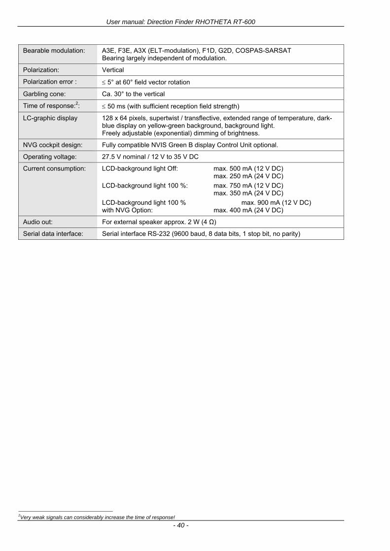
User manual Direction Finder RHOTHETA RT-600
- 40 -
Bearable modulation A3E F3E A3X (ELT-modulation) F1D G2D COSPAS-SARSAT Bearing largely independent of modulation
Polarization Vertical
Polarization error 5deg at 60deg field vector rotation
Garbling cone Ca 30deg to the vertical
Time of response2 50 ms (with sufficient reception field strength)
LC-graphic display 128 x 64 pixels supertwist transflective extended range of temperature dark-blue display on yellow-green background background light Freely adjustable (exponential) dimming of brightness
NVG cockpit design Fully compatible NVIS Green B display Control Unit optional
Operating voltage 275 V nominal 12 V to 35 V DC
Current consumption LCD-background light Off max 500 mA (12 V DC) max 250 mA (24 V DC)
LCD-background light 100 max 750 mA (12 V DC) max 350 mA (24 V DC)
LCD-background light 100 max 900 mA (12 V DC) with NVG Option max 400 mA (24 V DC)
Audio out For external speaker approx 2 W (4 Ω)
Serial data interface Serial interface RS-232 (9600 baud 8 data bits 1 stop bit no parity)
2Very weak signals can considerably increase the time of response
User manual Direction Finder RHOTHETA RT-600
- 41 -
52 Interface External connections (optional at Sub-D 9-pol Male connector)
Dimming
Pin 8
external voltage input for variable dimming of legends
(optional)
Analog input signal for variable control of the legends illumination Input voltage range is freely adjustable in the range of 15 hellip 28 V in the setup menu Refer to chapter ldquoSetup Pagerdquo Default setting 8 hellip28 V (8 V = Off 28 V = max dimming for legends)
Input Impedance gt 50 k
Pin 6 night status line for LCD
dimming (optional)
Low-active (as example switch to ground) At input voltage lt 25 VDC the LCD dimming operates in nightNVG mode Maximum brightness ca 4 of daydefault mode brightness
Input Impedance gt 50 k
Pin 4 NVG status line for LCD
dimming (optional)
Low-active (as example switch to ground) At input voltage lt 25 VDC the LCD dimming operates in nightNVG mode Maximum brightness ca 4 of daydefault mode brightness
Input Impedance gt 50 k
AudioLF
Pin 7 Audio output signal
AC coupled voltage source with very low inner resistance Maximum output voltage ca 8 VPP = 283V RMS at maximum Volume Maximum output power ca 2 W with 4 speaker
If a headphone is connected ([32hellip600] 100mW) we recommend using a resistor (18 025 W) between audio output and headphone to prevent damage of the headphone
Serial interface RS232 (9600 baud 8 data bits 1 stop bit no parity)
Pin 3 TXD Serial output (ca plusmn10 V)
Pin 2 RXD Serial input (ca plusmn10 V)
User manual Direction Finder RHOTHETA RT-600
- 42 -
53 Mechanical features
Temperature range
Display Control Unit permissible operating temperature3 -20 degC +60 degC permissible storage temperature -30 degC +80 degC
Antenna Unit permissible operating temperature3 -40 degC +60 degC permissible storage temperature -55 degC +80 degC
Protective system Antenna Unit IP 67
Weights Display Control Unit 250 g Antenna Unit 2000 g
Dimensions Display Control Unit 82 mm x 82 mm x 43 mm (width x height x depth) Antenna Unit 270 mm x 185 mm
Fig 48) DCU Mechanical Drawing (all dimensions in [mm])
3 For temperatures lower than ndash10deg C a warm-up period of 15 min should be allowed
User manual Direction Finder RHOTHETA RT-600
- 43 -
Fig 49) AU Mechanical Drawing (all dimensions in [mm])
User manual Direction Finder RHOTHETA RT-600
- 44 -
6 Appendix
61 Frequency Ranges
User manual Direction Finder RHOTHETA RT-600
- 45 -
62 Frequencies of channels on maritime band (only for standard [A] version) Frequency-range of the RT-600 in the maritime band 156000 MHz 162025 MHz
Channel No frequency (ship - station) Frequency (coast - station)
1 156050 MHz 160650 MHz 2 156100 MHz 160700 MHz 3 156150 MHz 160750 MHz 4 156200 MHz 160800 MHz 5 156250 MHz 160850 MHz 6 156300 MHz 160900 MHz 7 156350 MHz 160950 MHz 8 156400 MHz 9 156450 MHz
10 156500 MHz 11 156550 MHz 12 156600 MHz 13 156650 MHz 14 156700 MHz 15 156750 MHz 16 156800 MHz 17 156850 MHz 18 156900 MHz 161500 MHz 19 156950 MHz 161550 MHz 20 157000 MHz 161600 MHz 21 157050 MHz 161650 MHz 22 157100 MHz 161700 MHz 23 157150 MHz 161750 MHz 24 157200 MHz 161800 MHz 25 157250 MHz 161850 MHz 26 157300 MHz 161900 MHz 27 157350 MHz 161950 MHz 28 157400 MHz 162000 MHz 60 156025 MHz 160625 MHz 61 156075 MHz 160675 MHz 62 156125 MHz 160725 MHz 63 156175 MHz 160775 MHz 64 156225 MHz 160825 MHz 65 156275 MHz 160875 MHz 66 156325 MHz 160925 MHz 67 156375 MHz 68 156425 MHz 69 156475 MHz 70 156525 MHz 71 156575 MHz 72 156625 MHz 73 156675 MHz 74 156725 MHz 75 156775 MHz 76 156825 MHz 77 156875 MHz 78 156925 MHz 161525 MHz 79 156975 MHz 161575 MHz 80 157025 MHz 161625 MHz 81 157075 MHz 161675 MHz 82 157125 MHz 161725 MHz 83 157175 MHz 161775 MHz 84 157225 MHz 161825 MHz 85 157275 MHz 161875 MHz 86 157325 MHz 161925 MHz 87 157375 MHz 161975 MHz 88 157425 MHz 162025 MHz
User manual Direction Finder RHOTHETA RT-600
- 46 -
63 Serial interface data protocol (short description)
631 General
Interface parameters RS232 9600 Baud 8 databits 1 stopbit no parity LSB sent first Timing of serial data For accurate use of the serial data (even for the optional serial input commands) the correct timing is mandatory The DCU (Display Control Unit) sends out via the RS-232 Pins (see 43 System Interconnect Wiring Diagram page 38) cyclic and autonomous every approx 250300 ms a binary data stream which contains all relevant DF-bearing information The output data contains one or two blocks of binary data (see next picture with accordingly description) The optional serial input is only used if changes (as example frequency change) are done by additional remote control units
Fig 50) Timing of serial data
Serial standard output
This output data is always available and contains all relevant DF-bearing data For detailed content see page 47
Optional extended serial output
This data contains some additional information like as example CospasSarsat or LoJack decoding and ID data For detailed content see page 50 The data is only available with DCU Software [Rev ge 320] and if this optional data block is configured as ON = enabled (see Setup Edit Page point (10) )
Even to avoid compatibility problems with already existing older remote control software it is possible to disable switch off this additional data block (see Setup Edit Page point (10) )
Optional serial input
Only used for optional commands to control DCU parameters If as example the direction finder frequency is changed remotely there is send to the DCU one time this data block with the new frequency For detailed content see page 52
User manual Direction Finder RHOTHETA RT-600
- 47 -
632 Serial standard output (protocol description)
Specification serial standard output
The binary data stream with a length of 39 bytes starts with a header byte (value = hex 0xA0 as ID for DF Mode) The next bytes contain different values for status bearing information and also service The last byte is used for data stream checksum control Remark This is a binary data protocol So every byte value from 0dec hellip 255dec (0x00 hellip 0xFF) is possible Because of this it is not allowed to realize a start byte detection by the content (0xA0) The idle line detection is recommended for detection the end of message Register of databytes (for details see next page)
byte no
[0] Header = 0xA0 Id for DF Mode
[1] Number = 39 = bytes in the complete message (including header and checksumbyte)
[2] Status (1) HSB [x|x|x|x|x|x|x|x] LSB | | | | | | | --gt (0) Receiving | | | | | | ----gt (1) Squelch controlled by AU (X) | | | | | ------gt (2) Permission RL Calibration | | | | --------gt (3) Line Night | | | ----------gt (4) Line NVG | | ------------gt (5) Dimming External | --------------gt (6) Autosquelch Active ----------------gt (7) 0=Standard Version 1=LE Version
[3] Status (2) HSB [x|x|x|x|x|x|x|x] LSB | ----------------gt (7) 0=Standard 1=extended serial dataprotocol = ONactive
[45] Error (Bits[120])
[6] Actual DCU Page
[7] Volume [0hellip100]
[811] Frequency [Hz]
[12] Active Band
[13] Actual Squelchlevel [0hellip60]
[14] Audio-Line amp_NF_Test Output
[15] (Not used)
[1617] Voltage_DCU ([0hellip335]=[0 hellip 335]V
[1819] Voltage_AU ([0hellip255]=[0 hellip 255]V
[20] Temperature_AU [-68hellip+127]degC
[21] Frequency Offset [-99hellip+99]
[2225] ServiceTest values (mode dependent test values for service only)
26 (Not used reserved)
[27] Level [0hellip100]
[2829] Bearing Averaged [0hellip359]deg relative
[3031] Bearing Live_Min [0hellip359]deg relative
[3233] Bearing Live_Max [0hellip359]deg relative
[34] Test Value PS-RAM Right Rotation[0hellip178] (for service only)
[35] Test Value PS-RAM Left Rotation [0hellip178] (for service only)
[3637] (Not used reserved)
[38] Checksum is the 2rsquos complement of the modulo-256 sum of all bytes without checksum-byte [0n-1]
User manual Direction Finder RHOTHETA RT-600
- 48 -
Detailed Description of important values for practical use
Status byte [2] Receiving Bit 0 of this value (LSB) indicates signal receiving Bit 0 = 0 then no signal is received and so on no bearing is available Bit 0 = 1 then bearing is possible Bit 1 if(1) then Squelch is controlled by AU (active at modes CospasSarsat Decode CospasSarsat Scanning LoJack with Filter=ID only)
Error bytes [4hellip5] 16 bit value each set bit corresponds to the error no (Refer to the chapter Error messages) Example - 0x0000 No error - 0x0800 Bit No 11 Set ( = No AU Error)
Actual DCU Page byte [6] indicates actual operating mode of DCU 0 = Standard bearing page 1 = Frequency memory page 2 = CospasSarsat decoding page 3 = LoJack decoding page (ID edit)
Frequency bytes [8hellip11] 32 bit value actual adjusted frequency [Hz] Example - 0x073DF160 1215000000 121500 MHz
Active Band Standard Version [A] 0=VHF Airband 1=VHF Marineband sea 2=VHF Marineband coast 3=UHV Airband 4=CospasSarsat LE Version [L] 0=VHF Airband 1=LoJack 2=Lifesaver 3=ETS 4=CospasSarsat
Actual Squelchlevel byte [13] Range [0hellip60] without signal the actual squelchlevel should always be adjusted a little bit over the noise level (Refer to the chapter Squelch operation)
Level byte [27] Range [099] actual receiving level (without signal this value is equal to the noise level) If a signal is received then this value corresponds to the signal strength of this signal
Relative Bearing averaged byte [2829] 16 bit value Range [0hellip359 0xFFFF] if the value = 0xFFFF then no valid bearing is available otherwise this value contains the actual averaged bearing information in Deg [0deg359deg] Example - 0X0114 276deg bearing (= left side oriented to heading)
Bearing Live MinMax byte[3031] amp [3233] - 16 bit values Range [0hellip359 0xFFFF] Only for signal quality or additional information ndash NOT recommended for bearing indication The relative live bearing field contains the maxmin bearing in degrees without averaging The relative live bearing reacts faster than the normal relative bearing but it has not the precision of the averaged bearing The MinMax Bearing Values are calculated within a time period of approx 250 ms If they are very close together (for example ldquo124rdquo and ldquo128rdquo degrees) then the signal quality is quite good A wide span of the minmax values (for example ldquo97rdquo and ldquo162rdquo) shows very noisy but nevertheless bearable signal quality
User manual Direction Finder RHOTHETA RT-600
- 49 -
633 DCU Info output (protocol description)
Specification DCU Info output
Remark This protocol is only available while the SetupEdit page is activated at the DCU
byte no
[0] Header = 0xAF Id for DCU Info Mode
[1] Number = 39 = bytes in the complete message (including header and checksumbyte)
[2]
(see standard output) [3]
[45]
[621] Info String of 15 byteschars the string contains Information about Unit Variant Software Version and Serial No
Example Byte [318] =
|--AU ID---||Var-||---Software Version---| |-------------- Serial No---------------| [0x44][0x55][0x41][0x33][0x2E][0x33][0x30][0x3A][0x20][0x20][0x30][0x31][0x32][0x33][0x34][0x00] rsquoDrsquo rsquoUrsquo rsquoArsquo rsquo3rsquo rsquorsquo rsquo3rsquo rsquo0rsquo rsquorsquo rsquo rsquo rsquo rsquo rsquo0rsquo rsquo1rsquo rsquo2rsquo rsquo3rsquo rsquo4rsquo rsquoENDrsquo | | | | __________________ | | ________________________ | n n n | | n n n n n | (Software Version) | | (Serial No) | gt rsquoArsquo = Standard Variant gt rsquoLrsquo = Law Enforcement Variant
User manual Direction Finder RHOTHETA RT-600
- 50 -
634 Optional extended serial output (protocol description)
The data content depends on the actual mode of the direction finder To get special data the direction finder has first to be switched to the equivalent mode
COSPAS-SARSAT Decoding data
This data is only available and valid if Display Control Unit with actual software Rev ge 320 (see Power-On procedure page 10) Configuration of Extended serial = ON (see Setup Edit Page point (10) ) Direction Finder COSPAS-SARSAT decoding mode is activated by selecting the corresponding page
(see COSPAS-SARSAT Decode Window page 20 and page 21) and so on Header (byte 0 of data) = 0x91
A valid COSPAS-SARSAT decoding data protocol is always marked by the first data byte (header = 0x91) Always after receiving and decoding of a valid COSPAS-SARSAT pulse the complete data protocol with 33 bytes is send out one time
Byte No
[0] Header = 0x91 (Identification for CPSarsat decoding mode)
[1] Number of bytes - 7 if no decoded pulse is available - 33 if new pulse was received and is available
[2] Error
[3] Bit[0] - 0 =gt No new 406 MSG (decoded data) available - 1 =gt New valid 406 MSG available (Sync amp Frame Ok) Check Error Status for Bit-Errors
Bit[61] AutoSquelch Level valid range [060] ( decimal)
Bit[7] = 1 Squelch controlled by AU
[4] Signallevel of received signal valid range [099] ( decimal)
[5] Voltage of Antenna Unit Power Supply input valid range [80255] (decimal = 80 255 V DC)
[6] Temperature inside Antenna Unit valid range [-50+100] (degC signed byte value)
The following databytes are only available if a correct CPSarsat puls gets received and decoded with correct checksum
[724] 18 x Databytes complete orginal CPSarsat 406 decoded message (144 bit)
Databyte Nr [ Byte 7 ] [ Byte 8 ] [Byte9 Byte24] 406 MSG Bit Nr [1 2 3 4 5 6 7 8] [9 10 11 12 13 14 15 16] [17 144]
[25] SN-Flag valid values 0x53=rsquoSrsquo 0x4E=rsquoNrsquo 0x2D=rsquo-rsquo if no GPS data available
GPS-Position Latitude
[26] Deg valid values [090] (decimal Deg) 0xFF if no GPS data available
[27] Min valid values [059] (decimal Deg) 0xFF if no GPS data available
[28] Sec valid values [059] (decimal Deg) 0xFF if no GPS data available
[29] WE-Flag valid values 0x57=rsquoWrsquo 0x45=rsquoErsquo 0x2D=rsquo-rsquo if no GPS data available
GPS-Position Longitude
[30] Deg valid values [0180] (decimal Deg) 0xFF if no GPS data available
[31] Min valid values [059] (decimal Deg) 0xFF if no GPS data available
[32] Sec valid values [059] (decimal Deg) 0xFF if no GPS data available
User manual Direction Finder RHOTHETA RT-600
- 51 -
LoJack ID data
This data is only available and valid if Display Control Unit with actual software Rev ge 320 (see Power-On procedure page 10) Direction Finder of variant [L] Law Enforcement Configuration of Extended serial = ON (see Setup Edit Page point (10) ) Direction Finder is working with active LoJack gtID Filterlt Header (byte 0 of data) = 0x93 or 0x94
Valid LoJack ID decoding data is always marked by the first data byte (header = 0x93 or 0x94)
Byte No
[0] Header = 0x93 LoJack ID editing sub-page is selected Filter = VLU all valid and received LoJack pulses are indicated = 0x94 Lojack Decode amp DF Mode with active Filter = ID
[1] Number of bytes in the complete data stream - decimal 26 = default value
[2] Nonrelevant
[3] Bit[0] Receiving OnOff - 0 =gt No Receiving no bearing - 1 =gt new LoJack pulse received
[412] Nonrelevant
[1317] Lojack ID
Replay Code 5 x ASCII Chars ldquoNo BIOZrdquo set
Example ASCII = ldquo000R1rdquo
18 Receiver Level Out Max [099]
19
LoJack Decoder Status [07] - 0 Off - 1 Wait for Preamble - 2 Preamble Ok - 3 FlagPattern Ok - 4 Data BitError gt 1 - 5 Data Ok (No VLU) - 6 VLU Ok - 7 ID Ok (Filter=IDONLY)
[2025] Nonrelevant
Remark Only if byte no [3] bit [0] gets ldquo1rdquo (Receiving On) then an active LoJack pulse is received and so on the corresponding LoJack ID valid otherwise the LoJack ID only shows the actual adjusted LoJack Filter ID of the direction finder
User manual Direction Finder RHOTHETA RT-600
- 52 -
635 Optional serial input (protocol description)
Specification serial input (optional)
The serial input is normally used for service and maintenance only Nevertheless it is possible via this interface to remote control the actual frequency and the squelchlevel of the DF system If a valid data stream is send to the DF then the actual frequency selection at the DCU is switched to Block2 AUX0 At this memory channel the new frequency is stored and used automatically (Refer to the chapter Frequency Selection Page) If the frequency is changed (by one valid data stream) no more serial input is necessary The actual frequency can be changed again at any time by manual operation at the DCU The timing of serial input (if used) is strictly fixed The optional serial input has to take place directly after a complete serial output (max 50 ms delay time) If a new changed frequency is commanded to the DCU via this serial input interface it can take up to 1 sec of time until this new frequency is ready for operationbearing It is strictly not recommended to use the frequency remote control for any scan mode The frequency control has to be used for static frequency change only Register of databytes
byte no
[0] Header 0xC0
[1] Number of bytes in the complete message (including header and checksumbyte)
[23] (not used for normal operation any byte values allowed)
[4] Volume [0100]
[58] Frequency [Hz] (frequency is rounded to the according grid automatically)
Valid Range for Standard Version Valid Range for LE Version
118000000 hellip 123000000 [Hz] 8333 kHz 118000000 hellip 123000000 [Hz] 8333 kHz
156050000 hellip 162025000 [Hz] 5000 kHz 164000000 hellip 174000000 [Hz] 8333 kHz
201000000 hellip 215995000 [Hz] 5000 kHz
240000000 hellip 246000000 [Hz] 8333 kHz 216000000 hellip 218995000 [Hz] 12500 kHz219000000 hellip 220000000 [Hz] 10000 kHz
400000000 hellip 410000000 [Hz] 8333 kHz 400000000 hellip 410000000 [Hz] 8333 kHz
[9] Squelchlevel Manual = [0hellip60] Autosql= [ -1] Warning use only for pulsed signals (as example CpSarsat LoJack)
[10] (not used for normal operation any byte values allowed)
[11] Internal Dimming [0100]
[12] Checksum is the 2rsquos complement of the modulo-256 sum of all bytes without checksum-byte [0n-1]
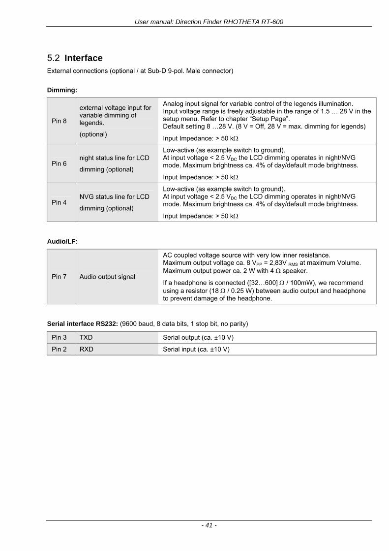
User manual Direction Finder RHOTHETA RT-600
- 41 -
52 Interface External connections (optional at Sub-D 9-pol Male connector)
Dimming
Pin 8
external voltage input for variable dimming of legends
(optional)
Analog input signal for variable control of the legends illumination Input voltage range is freely adjustable in the range of 15 hellip 28 V in the setup menu Refer to chapter ldquoSetup Pagerdquo Default setting 8 hellip28 V (8 V = Off 28 V = max dimming for legends)
Input Impedance gt 50 k
Pin 6 night status line for LCD
dimming (optional)
Low-active (as example switch to ground) At input voltage lt 25 VDC the LCD dimming operates in nightNVG mode Maximum brightness ca 4 of daydefault mode brightness
Input Impedance gt 50 k
Pin 4 NVG status line for LCD
dimming (optional)
Low-active (as example switch to ground) At input voltage lt 25 VDC the LCD dimming operates in nightNVG mode Maximum brightness ca 4 of daydefault mode brightness
Input Impedance gt 50 k
AudioLF
Pin 7 Audio output signal
AC coupled voltage source with very low inner resistance Maximum output voltage ca 8 VPP = 283V RMS at maximum Volume Maximum output power ca 2 W with 4 speaker
If a headphone is connected ([32hellip600] 100mW) we recommend using a resistor (18 025 W) between audio output and headphone to prevent damage of the headphone
Serial interface RS232 (9600 baud 8 data bits 1 stop bit no parity)
Pin 3 TXD Serial output (ca plusmn10 V)
Pin 2 RXD Serial input (ca plusmn10 V)
User manual Direction Finder RHOTHETA RT-600
- 42 -
53 Mechanical features
Temperature range
Display Control Unit permissible operating temperature3 -20 degC +60 degC permissible storage temperature -30 degC +80 degC
Antenna Unit permissible operating temperature3 -40 degC +60 degC permissible storage temperature -55 degC +80 degC
Protective system Antenna Unit IP 67
Weights Display Control Unit 250 g Antenna Unit 2000 g
Dimensions Display Control Unit 82 mm x 82 mm x 43 mm (width x height x depth) Antenna Unit 270 mm x 185 mm
Fig 48) DCU Mechanical Drawing (all dimensions in [mm])
3 For temperatures lower than ndash10deg C a warm-up period of 15 min should be allowed
User manual Direction Finder RHOTHETA RT-600
- 43 -
Fig 49) AU Mechanical Drawing (all dimensions in [mm])
User manual Direction Finder RHOTHETA RT-600
- 44 -
6 Appendix
61 Frequency Ranges
User manual Direction Finder RHOTHETA RT-600
- 45 -
62 Frequencies of channels on maritime band (only for standard [A] version) Frequency-range of the RT-600 in the maritime band 156000 MHz 162025 MHz
Channel No frequency (ship - station) Frequency (coast - station)
1 156050 MHz 160650 MHz 2 156100 MHz 160700 MHz 3 156150 MHz 160750 MHz 4 156200 MHz 160800 MHz 5 156250 MHz 160850 MHz 6 156300 MHz 160900 MHz 7 156350 MHz 160950 MHz 8 156400 MHz 9 156450 MHz
10 156500 MHz 11 156550 MHz 12 156600 MHz 13 156650 MHz 14 156700 MHz 15 156750 MHz 16 156800 MHz 17 156850 MHz 18 156900 MHz 161500 MHz 19 156950 MHz 161550 MHz 20 157000 MHz 161600 MHz 21 157050 MHz 161650 MHz 22 157100 MHz 161700 MHz 23 157150 MHz 161750 MHz 24 157200 MHz 161800 MHz 25 157250 MHz 161850 MHz 26 157300 MHz 161900 MHz 27 157350 MHz 161950 MHz 28 157400 MHz 162000 MHz 60 156025 MHz 160625 MHz 61 156075 MHz 160675 MHz 62 156125 MHz 160725 MHz 63 156175 MHz 160775 MHz 64 156225 MHz 160825 MHz 65 156275 MHz 160875 MHz 66 156325 MHz 160925 MHz 67 156375 MHz 68 156425 MHz 69 156475 MHz 70 156525 MHz 71 156575 MHz 72 156625 MHz 73 156675 MHz 74 156725 MHz 75 156775 MHz 76 156825 MHz 77 156875 MHz 78 156925 MHz 161525 MHz 79 156975 MHz 161575 MHz 80 157025 MHz 161625 MHz 81 157075 MHz 161675 MHz 82 157125 MHz 161725 MHz 83 157175 MHz 161775 MHz 84 157225 MHz 161825 MHz 85 157275 MHz 161875 MHz 86 157325 MHz 161925 MHz 87 157375 MHz 161975 MHz 88 157425 MHz 162025 MHz
User manual Direction Finder RHOTHETA RT-600
- 46 -
63 Serial interface data protocol (short description)
631 General
Interface parameters RS232 9600 Baud 8 databits 1 stopbit no parity LSB sent first Timing of serial data For accurate use of the serial data (even for the optional serial input commands) the correct timing is mandatory The DCU (Display Control Unit) sends out via the RS-232 Pins (see 43 System Interconnect Wiring Diagram page 38) cyclic and autonomous every approx 250300 ms a binary data stream which contains all relevant DF-bearing information The output data contains one or two blocks of binary data (see next picture with accordingly description) The optional serial input is only used if changes (as example frequency change) are done by additional remote control units
Fig 50) Timing of serial data
Serial standard output
This output data is always available and contains all relevant DF-bearing data For detailed content see page 47
Optional extended serial output
This data contains some additional information like as example CospasSarsat or LoJack decoding and ID data For detailed content see page 50 The data is only available with DCU Software [Rev ge 320] and if this optional data block is configured as ON = enabled (see Setup Edit Page point (10) )
Even to avoid compatibility problems with already existing older remote control software it is possible to disable switch off this additional data block (see Setup Edit Page point (10) )
Optional serial input
Only used for optional commands to control DCU parameters If as example the direction finder frequency is changed remotely there is send to the DCU one time this data block with the new frequency For detailed content see page 52
User manual Direction Finder RHOTHETA RT-600
- 47 -
632 Serial standard output (protocol description)
Specification serial standard output
The binary data stream with a length of 39 bytes starts with a header byte (value = hex 0xA0 as ID for DF Mode) The next bytes contain different values for status bearing information and also service The last byte is used for data stream checksum control Remark This is a binary data protocol So every byte value from 0dec hellip 255dec (0x00 hellip 0xFF) is possible Because of this it is not allowed to realize a start byte detection by the content (0xA0) The idle line detection is recommended for detection the end of message Register of databytes (for details see next page)
byte no
[0] Header = 0xA0 Id for DF Mode
[1] Number = 39 = bytes in the complete message (including header and checksumbyte)
[2] Status (1) HSB [x|x|x|x|x|x|x|x] LSB | | | | | | | --gt (0) Receiving | | | | | | ----gt (1) Squelch controlled by AU (X) | | | | | ------gt (2) Permission RL Calibration | | | | --------gt (3) Line Night | | | ----------gt (4) Line NVG | | ------------gt (5) Dimming External | --------------gt (6) Autosquelch Active ----------------gt (7) 0=Standard Version 1=LE Version
[3] Status (2) HSB [x|x|x|x|x|x|x|x] LSB | ----------------gt (7) 0=Standard 1=extended serial dataprotocol = ONactive
[45] Error (Bits[120])
[6] Actual DCU Page
[7] Volume [0hellip100]
[811] Frequency [Hz]
[12] Active Band
[13] Actual Squelchlevel [0hellip60]
[14] Audio-Line amp_NF_Test Output
[15] (Not used)
[1617] Voltage_DCU ([0hellip335]=[0 hellip 335]V
[1819] Voltage_AU ([0hellip255]=[0 hellip 255]V
[20] Temperature_AU [-68hellip+127]degC
[21] Frequency Offset [-99hellip+99]
[2225] ServiceTest values (mode dependent test values for service only)
26 (Not used reserved)
[27] Level [0hellip100]
[2829] Bearing Averaged [0hellip359]deg relative
[3031] Bearing Live_Min [0hellip359]deg relative
[3233] Bearing Live_Max [0hellip359]deg relative
[34] Test Value PS-RAM Right Rotation[0hellip178] (for service only)
[35] Test Value PS-RAM Left Rotation [0hellip178] (for service only)
[3637] (Not used reserved)
[38] Checksum is the 2rsquos complement of the modulo-256 sum of all bytes without checksum-byte [0n-1]
User manual Direction Finder RHOTHETA RT-600
- 48 -
Detailed Description of important values for practical use
Status byte [2] Receiving Bit 0 of this value (LSB) indicates signal receiving Bit 0 = 0 then no signal is received and so on no bearing is available Bit 0 = 1 then bearing is possible Bit 1 if(1) then Squelch is controlled by AU (active at modes CospasSarsat Decode CospasSarsat Scanning LoJack with Filter=ID only)
Error bytes [4hellip5] 16 bit value each set bit corresponds to the error no (Refer to the chapter Error messages) Example - 0x0000 No error - 0x0800 Bit No 11 Set ( = No AU Error)
Actual DCU Page byte [6] indicates actual operating mode of DCU 0 = Standard bearing page 1 = Frequency memory page 2 = CospasSarsat decoding page 3 = LoJack decoding page (ID edit)
Frequency bytes [8hellip11] 32 bit value actual adjusted frequency [Hz] Example - 0x073DF160 1215000000 121500 MHz
Active Band Standard Version [A] 0=VHF Airband 1=VHF Marineband sea 2=VHF Marineband coast 3=UHV Airband 4=CospasSarsat LE Version [L] 0=VHF Airband 1=LoJack 2=Lifesaver 3=ETS 4=CospasSarsat
Actual Squelchlevel byte [13] Range [0hellip60] without signal the actual squelchlevel should always be adjusted a little bit over the noise level (Refer to the chapter Squelch operation)
Level byte [27] Range [099] actual receiving level (without signal this value is equal to the noise level) If a signal is received then this value corresponds to the signal strength of this signal
Relative Bearing averaged byte [2829] 16 bit value Range [0hellip359 0xFFFF] if the value = 0xFFFF then no valid bearing is available otherwise this value contains the actual averaged bearing information in Deg [0deg359deg] Example - 0X0114 276deg bearing (= left side oriented to heading)
Bearing Live MinMax byte[3031] amp [3233] - 16 bit values Range [0hellip359 0xFFFF] Only for signal quality or additional information ndash NOT recommended for bearing indication The relative live bearing field contains the maxmin bearing in degrees without averaging The relative live bearing reacts faster than the normal relative bearing but it has not the precision of the averaged bearing The MinMax Bearing Values are calculated within a time period of approx 250 ms If they are very close together (for example ldquo124rdquo and ldquo128rdquo degrees) then the signal quality is quite good A wide span of the minmax values (for example ldquo97rdquo and ldquo162rdquo) shows very noisy but nevertheless bearable signal quality
User manual Direction Finder RHOTHETA RT-600
- 49 -
633 DCU Info output (protocol description)
Specification DCU Info output
Remark This protocol is only available while the SetupEdit page is activated at the DCU
byte no
[0] Header = 0xAF Id for DCU Info Mode
[1] Number = 39 = bytes in the complete message (including header and checksumbyte)
[2]
(see standard output) [3]
[45]
[621] Info String of 15 byteschars the string contains Information about Unit Variant Software Version and Serial No
Example Byte [318] =
|--AU ID---||Var-||---Software Version---| |-------------- Serial No---------------| [0x44][0x55][0x41][0x33][0x2E][0x33][0x30][0x3A][0x20][0x20][0x30][0x31][0x32][0x33][0x34][0x00] rsquoDrsquo rsquoUrsquo rsquoArsquo rsquo3rsquo rsquorsquo rsquo3rsquo rsquo0rsquo rsquorsquo rsquo rsquo rsquo rsquo rsquo0rsquo rsquo1rsquo rsquo2rsquo rsquo3rsquo rsquo4rsquo rsquoENDrsquo | | | | __________________ | | ________________________ | n n n | | n n n n n | (Software Version) | | (Serial No) | gt rsquoArsquo = Standard Variant gt rsquoLrsquo = Law Enforcement Variant
User manual Direction Finder RHOTHETA RT-600
- 50 -
634 Optional extended serial output (protocol description)
The data content depends on the actual mode of the direction finder To get special data the direction finder has first to be switched to the equivalent mode
COSPAS-SARSAT Decoding data
This data is only available and valid if Display Control Unit with actual software Rev ge 320 (see Power-On procedure page 10) Configuration of Extended serial = ON (see Setup Edit Page point (10) ) Direction Finder COSPAS-SARSAT decoding mode is activated by selecting the corresponding page
(see COSPAS-SARSAT Decode Window page 20 and page 21) and so on Header (byte 0 of data) = 0x91
A valid COSPAS-SARSAT decoding data protocol is always marked by the first data byte (header = 0x91) Always after receiving and decoding of a valid COSPAS-SARSAT pulse the complete data protocol with 33 bytes is send out one time
Byte No
[0] Header = 0x91 (Identification for CPSarsat decoding mode)
[1] Number of bytes - 7 if no decoded pulse is available - 33 if new pulse was received and is available
[2] Error
[3] Bit[0] - 0 =gt No new 406 MSG (decoded data) available - 1 =gt New valid 406 MSG available (Sync amp Frame Ok) Check Error Status for Bit-Errors
Bit[61] AutoSquelch Level valid range [060] ( decimal)
Bit[7] = 1 Squelch controlled by AU
[4] Signallevel of received signal valid range [099] ( decimal)
[5] Voltage of Antenna Unit Power Supply input valid range [80255] (decimal = 80 255 V DC)
[6] Temperature inside Antenna Unit valid range [-50+100] (degC signed byte value)
The following databytes are only available if a correct CPSarsat puls gets received and decoded with correct checksum
[724] 18 x Databytes complete orginal CPSarsat 406 decoded message (144 bit)
Databyte Nr [ Byte 7 ] [ Byte 8 ] [Byte9 Byte24] 406 MSG Bit Nr [1 2 3 4 5 6 7 8] [9 10 11 12 13 14 15 16] [17 144]
[25] SN-Flag valid values 0x53=rsquoSrsquo 0x4E=rsquoNrsquo 0x2D=rsquo-rsquo if no GPS data available
GPS-Position Latitude
[26] Deg valid values [090] (decimal Deg) 0xFF if no GPS data available
[27] Min valid values [059] (decimal Deg) 0xFF if no GPS data available
[28] Sec valid values [059] (decimal Deg) 0xFF if no GPS data available
[29] WE-Flag valid values 0x57=rsquoWrsquo 0x45=rsquoErsquo 0x2D=rsquo-rsquo if no GPS data available
GPS-Position Longitude
[30] Deg valid values [0180] (decimal Deg) 0xFF if no GPS data available
[31] Min valid values [059] (decimal Deg) 0xFF if no GPS data available
[32] Sec valid values [059] (decimal Deg) 0xFF if no GPS data available
User manual Direction Finder RHOTHETA RT-600
- 51 -
LoJack ID data
This data is only available and valid if Display Control Unit with actual software Rev ge 320 (see Power-On procedure page 10) Direction Finder of variant [L] Law Enforcement Configuration of Extended serial = ON (see Setup Edit Page point (10) ) Direction Finder is working with active LoJack gtID Filterlt Header (byte 0 of data) = 0x93 or 0x94
Valid LoJack ID decoding data is always marked by the first data byte (header = 0x93 or 0x94)
Byte No
[0] Header = 0x93 LoJack ID editing sub-page is selected Filter = VLU all valid and received LoJack pulses are indicated = 0x94 Lojack Decode amp DF Mode with active Filter = ID
[1] Number of bytes in the complete data stream - decimal 26 = default value
[2] Nonrelevant
[3] Bit[0] Receiving OnOff - 0 =gt No Receiving no bearing - 1 =gt new LoJack pulse received
[412] Nonrelevant
[1317] Lojack ID
Replay Code 5 x ASCII Chars ldquoNo BIOZrdquo set
Example ASCII = ldquo000R1rdquo
18 Receiver Level Out Max [099]
19
LoJack Decoder Status [07] - 0 Off - 1 Wait for Preamble - 2 Preamble Ok - 3 FlagPattern Ok - 4 Data BitError gt 1 - 5 Data Ok (No VLU) - 6 VLU Ok - 7 ID Ok (Filter=IDONLY)
[2025] Nonrelevant
Remark Only if byte no [3] bit [0] gets ldquo1rdquo (Receiving On) then an active LoJack pulse is received and so on the corresponding LoJack ID valid otherwise the LoJack ID only shows the actual adjusted LoJack Filter ID of the direction finder
User manual Direction Finder RHOTHETA RT-600
- 52 -
635 Optional serial input (protocol description)
Specification serial input (optional)
The serial input is normally used for service and maintenance only Nevertheless it is possible via this interface to remote control the actual frequency and the squelchlevel of the DF system If a valid data stream is send to the DF then the actual frequency selection at the DCU is switched to Block2 AUX0 At this memory channel the new frequency is stored and used automatically (Refer to the chapter Frequency Selection Page) If the frequency is changed (by one valid data stream) no more serial input is necessary The actual frequency can be changed again at any time by manual operation at the DCU The timing of serial input (if used) is strictly fixed The optional serial input has to take place directly after a complete serial output (max 50 ms delay time) If a new changed frequency is commanded to the DCU via this serial input interface it can take up to 1 sec of time until this new frequency is ready for operationbearing It is strictly not recommended to use the frequency remote control for any scan mode The frequency control has to be used for static frequency change only Register of databytes
byte no
[0] Header 0xC0
[1] Number of bytes in the complete message (including header and checksumbyte)
[23] (not used for normal operation any byte values allowed)
[4] Volume [0100]
[58] Frequency [Hz] (frequency is rounded to the according grid automatically)
Valid Range for Standard Version Valid Range for LE Version
118000000 hellip 123000000 [Hz] 8333 kHz 118000000 hellip 123000000 [Hz] 8333 kHz
156050000 hellip 162025000 [Hz] 5000 kHz 164000000 hellip 174000000 [Hz] 8333 kHz
201000000 hellip 215995000 [Hz] 5000 kHz
240000000 hellip 246000000 [Hz] 8333 kHz 216000000 hellip 218995000 [Hz] 12500 kHz219000000 hellip 220000000 [Hz] 10000 kHz
400000000 hellip 410000000 [Hz] 8333 kHz 400000000 hellip 410000000 [Hz] 8333 kHz
[9] Squelchlevel Manual = [0hellip60] Autosql= [ -1] Warning use only for pulsed signals (as example CpSarsat LoJack)
[10] (not used for normal operation any byte values allowed)
[11] Internal Dimming [0100]
[12] Checksum is the 2rsquos complement of the modulo-256 sum of all bytes without checksum-byte [0n-1]
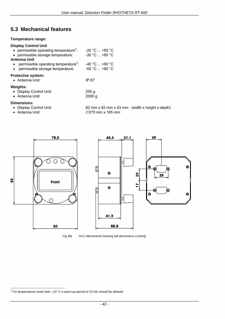
User manual Direction Finder RHOTHETA RT-600
- 42 -
53 Mechanical features
Temperature range
Display Control Unit permissible operating temperature3 -20 degC +60 degC permissible storage temperature -30 degC +80 degC
Antenna Unit permissible operating temperature3 -40 degC +60 degC permissible storage temperature -55 degC +80 degC
Protective system Antenna Unit IP 67
Weights Display Control Unit 250 g Antenna Unit 2000 g
Dimensions Display Control Unit 82 mm x 82 mm x 43 mm (width x height x depth) Antenna Unit 270 mm x 185 mm
Fig 48) DCU Mechanical Drawing (all dimensions in [mm])
3 For temperatures lower than ndash10deg C a warm-up period of 15 min should be allowed
User manual Direction Finder RHOTHETA RT-600
- 43 -
Fig 49) AU Mechanical Drawing (all dimensions in [mm])
User manual Direction Finder RHOTHETA RT-600
- 44 -
6 Appendix
61 Frequency Ranges
User manual Direction Finder RHOTHETA RT-600
- 45 -
62 Frequencies of channels on maritime band (only for standard [A] version) Frequency-range of the RT-600 in the maritime band 156000 MHz 162025 MHz
Channel No frequency (ship - station) Frequency (coast - station)
1 156050 MHz 160650 MHz 2 156100 MHz 160700 MHz 3 156150 MHz 160750 MHz 4 156200 MHz 160800 MHz 5 156250 MHz 160850 MHz 6 156300 MHz 160900 MHz 7 156350 MHz 160950 MHz 8 156400 MHz 9 156450 MHz
10 156500 MHz 11 156550 MHz 12 156600 MHz 13 156650 MHz 14 156700 MHz 15 156750 MHz 16 156800 MHz 17 156850 MHz 18 156900 MHz 161500 MHz 19 156950 MHz 161550 MHz 20 157000 MHz 161600 MHz 21 157050 MHz 161650 MHz 22 157100 MHz 161700 MHz 23 157150 MHz 161750 MHz 24 157200 MHz 161800 MHz 25 157250 MHz 161850 MHz 26 157300 MHz 161900 MHz 27 157350 MHz 161950 MHz 28 157400 MHz 162000 MHz 60 156025 MHz 160625 MHz 61 156075 MHz 160675 MHz 62 156125 MHz 160725 MHz 63 156175 MHz 160775 MHz 64 156225 MHz 160825 MHz 65 156275 MHz 160875 MHz 66 156325 MHz 160925 MHz 67 156375 MHz 68 156425 MHz 69 156475 MHz 70 156525 MHz 71 156575 MHz 72 156625 MHz 73 156675 MHz 74 156725 MHz 75 156775 MHz 76 156825 MHz 77 156875 MHz 78 156925 MHz 161525 MHz 79 156975 MHz 161575 MHz 80 157025 MHz 161625 MHz 81 157075 MHz 161675 MHz 82 157125 MHz 161725 MHz 83 157175 MHz 161775 MHz 84 157225 MHz 161825 MHz 85 157275 MHz 161875 MHz 86 157325 MHz 161925 MHz 87 157375 MHz 161975 MHz 88 157425 MHz 162025 MHz
User manual Direction Finder RHOTHETA RT-600
- 46 -
63 Serial interface data protocol (short description)
631 General
Interface parameters RS232 9600 Baud 8 databits 1 stopbit no parity LSB sent first Timing of serial data For accurate use of the serial data (even for the optional serial input commands) the correct timing is mandatory The DCU (Display Control Unit) sends out via the RS-232 Pins (see 43 System Interconnect Wiring Diagram page 38) cyclic and autonomous every approx 250300 ms a binary data stream which contains all relevant DF-bearing information The output data contains one or two blocks of binary data (see next picture with accordingly description) The optional serial input is only used if changes (as example frequency change) are done by additional remote control units
Fig 50) Timing of serial data
Serial standard output
This output data is always available and contains all relevant DF-bearing data For detailed content see page 47
Optional extended serial output
This data contains some additional information like as example CospasSarsat or LoJack decoding and ID data For detailed content see page 50 The data is only available with DCU Software [Rev ge 320] and if this optional data block is configured as ON = enabled (see Setup Edit Page point (10) )
Even to avoid compatibility problems with already existing older remote control software it is possible to disable switch off this additional data block (see Setup Edit Page point (10) )
Optional serial input
Only used for optional commands to control DCU parameters If as example the direction finder frequency is changed remotely there is send to the DCU one time this data block with the new frequency For detailed content see page 52
User manual Direction Finder RHOTHETA RT-600
- 47 -
632 Serial standard output (protocol description)
Specification serial standard output
The binary data stream with a length of 39 bytes starts with a header byte (value = hex 0xA0 as ID for DF Mode) The next bytes contain different values for status bearing information and also service The last byte is used for data stream checksum control Remark This is a binary data protocol So every byte value from 0dec hellip 255dec (0x00 hellip 0xFF) is possible Because of this it is not allowed to realize a start byte detection by the content (0xA0) The idle line detection is recommended for detection the end of message Register of databytes (for details see next page)
byte no
[0] Header = 0xA0 Id for DF Mode
[1] Number = 39 = bytes in the complete message (including header and checksumbyte)
[2] Status (1) HSB [x|x|x|x|x|x|x|x] LSB | | | | | | | --gt (0) Receiving | | | | | | ----gt (1) Squelch controlled by AU (X) | | | | | ------gt (2) Permission RL Calibration | | | | --------gt (3) Line Night | | | ----------gt (4) Line NVG | | ------------gt (5) Dimming External | --------------gt (6) Autosquelch Active ----------------gt (7) 0=Standard Version 1=LE Version
[3] Status (2) HSB [x|x|x|x|x|x|x|x] LSB | ----------------gt (7) 0=Standard 1=extended serial dataprotocol = ONactive
[45] Error (Bits[120])
[6] Actual DCU Page
[7] Volume [0hellip100]
[811] Frequency [Hz]
[12] Active Band
[13] Actual Squelchlevel [0hellip60]
[14] Audio-Line amp_NF_Test Output
[15] (Not used)
[1617] Voltage_DCU ([0hellip335]=[0 hellip 335]V
[1819] Voltage_AU ([0hellip255]=[0 hellip 255]V
[20] Temperature_AU [-68hellip+127]degC
[21] Frequency Offset [-99hellip+99]
[2225] ServiceTest values (mode dependent test values for service only)
26 (Not used reserved)
[27] Level [0hellip100]
[2829] Bearing Averaged [0hellip359]deg relative
[3031] Bearing Live_Min [0hellip359]deg relative
[3233] Bearing Live_Max [0hellip359]deg relative
[34] Test Value PS-RAM Right Rotation[0hellip178] (for service only)
[35] Test Value PS-RAM Left Rotation [0hellip178] (for service only)
[3637] (Not used reserved)
[38] Checksum is the 2rsquos complement of the modulo-256 sum of all bytes without checksum-byte [0n-1]
User manual Direction Finder RHOTHETA RT-600
- 48 -
Detailed Description of important values for practical use
Status byte [2] Receiving Bit 0 of this value (LSB) indicates signal receiving Bit 0 = 0 then no signal is received and so on no bearing is available Bit 0 = 1 then bearing is possible Bit 1 if(1) then Squelch is controlled by AU (active at modes CospasSarsat Decode CospasSarsat Scanning LoJack with Filter=ID only)
Error bytes [4hellip5] 16 bit value each set bit corresponds to the error no (Refer to the chapter Error messages) Example - 0x0000 No error - 0x0800 Bit No 11 Set ( = No AU Error)
Actual DCU Page byte [6] indicates actual operating mode of DCU 0 = Standard bearing page 1 = Frequency memory page 2 = CospasSarsat decoding page 3 = LoJack decoding page (ID edit)
Frequency bytes [8hellip11] 32 bit value actual adjusted frequency [Hz] Example - 0x073DF160 1215000000 121500 MHz
Active Band Standard Version [A] 0=VHF Airband 1=VHF Marineband sea 2=VHF Marineband coast 3=UHV Airband 4=CospasSarsat LE Version [L] 0=VHF Airband 1=LoJack 2=Lifesaver 3=ETS 4=CospasSarsat
Actual Squelchlevel byte [13] Range [0hellip60] without signal the actual squelchlevel should always be adjusted a little bit over the noise level (Refer to the chapter Squelch operation)
Level byte [27] Range [099] actual receiving level (without signal this value is equal to the noise level) If a signal is received then this value corresponds to the signal strength of this signal
Relative Bearing averaged byte [2829] 16 bit value Range [0hellip359 0xFFFF] if the value = 0xFFFF then no valid bearing is available otherwise this value contains the actual averaged bearing information in Deg [0deg359deg] Example - 0X0114 276deg bearing (= left side oriented to heading)
Bearing Live MinMax byte[3031] amp [3233] - 16 bit values Range [0hellip359 0xFFFF] Only for signal quality or additional information ndash NOT recommended for bearing indication The relative live bearing field contains the maxmin bearing in degrees without averaging The relative live bearing reacts faster than the normal relative bearing but it has not the precision of the averaged bearing The MinMax Bearing Values are calculated within a time period of approx 250 ms If they are very close together (for example ldquo124rdquo and ldquo128rdquo degrees) then the signal quality is quite good A wide span of the minmax values (for example ldquo97rdquo and ldquo162rdquo) shows very noisy but nevertheless bearable signal quality
User manual Direction Finder RHOTHETA RT-600
- 49 -
633 DCU Info output (protocol description)
Specification DCU Info output
Remark This protocol is only available while the SetupEdit page is activated at the DCU
byte no
[0] Header = 0xAF Id for DCU Info Mode
[1] Number = 39 = bytes in the complete message (including header and checksumbyte)
[2]
(see standard output) [3]
[45]
[621] Info String of 15 byteschars the string contains Information about Unit Variant Software Version and Serial No
Example Byte [318] =
|--AU ID---||Var-||---Software Version---| |-------------- Serial No---------------| [0x44][0x55][0x41][0x33][0x2E][0x33][0x30][0x3A][0x20][0x20][0x30][0x31][0x32][0x33][0x34][0x00] rsquoDrsquo rsquoUrsquo rsquoArsquo rsquo3rsquo rsquorsquo rsquo3rsquo rsquo0rsquo rsquorsquo rsquo rsquo rsquo rsquo rsquo0rsquo rsquo1rsquo rsquo2rsquo rsquo3rsquo rsquo4rsquo rsquoENDrsquo | | | | __________________ | | ________________________ | n n n | | n n n n n | (Software Version) | | (Serial No) | gt rsquoArsquo = Standard Variant gt rsquoLrsquo = Law Enforcement Variant
User manual Direction Finder RHOTHETA RT-600
- 50 -
634 Optional extended serial output (protocol description)
The data content depends on the actual mode of the direction finder To get special data the direction finder has first to be switched to the equivalent mode
COSPAS-SARSAT Decoding data
This data is only available and valid if Display Control Unit with actual software Rev ge 320 (see Power-On procedure page 10) Configuration of Extended serial = ON (see Setup Edit Page point (10) ) Direction Finder COSPAS-SARSAT decoding mode is activated by selecting the corresponding page
(see COSPAS-SARSAT Decode Window page 20 and page 21) and so on Header (byte 0 of data) = 0x91
A valid COSPAS-SARSAT decoding data protocol is always marked by the first data byte (header = 0x91) Always after receiving and decoding of a valid COSPAS-SARSAT pulse the complete data protocol with 33 bytes is send out one time
Byte No
[0] Header = 0x91 (Identification for CPSarsat decoding mode)
[1] Number of bytes - 7 if no decoded pulse is available - 33 if new pulse was received and is available
[2] Error
[3] Bit[0] - 0 =gt No new 406 MSG (decoded data) available - 1 =gt New valid 406 MSG available (Sync amp Frame Ok) Check Error Status for Bit-Errors
Bit[61] AutoSquelch Level valid range [060] ( decimal)
Bit[7] = 1 Squelch controlled by AU
[4] Signallevel of received signal valid range [099] ( decimal)
[5] Voltage of Antenna Unit Power Supply input valid range [80255] (decimal = 80 255 V DC)
[6] Temperature inside Antenna Unit valid range [-50+100] (degC signed byte value)
The following databytes are only available if a correct CPSarsat puls gets received and decoded with correct checksum
[724] 18 x Databytes complete orginal CPSarsat 406 decoded message (144 bit)
Databyte Nr [ Byte 7 ] [ Byte 8 ] [Byte9 Byte24] 406 MSG Bit Nr [1 2 3 4 5 6 7 8] [9 10 11 12 13 14 15 16] [17 144]
[25] SN-Flag valid values 0x53=rsquoSrsquo 0x4E=rsquoNrsquo 0x2D=rsquo-rsquo if no GPS data available
GPS-Position Latitude
[26] Deg valid values [090] (decimal Deg) 0xFF if no GPS data available
[27] Min valid values [059] (decimal Deg) 0xFF if no GPS data available
[28] Sec valid values [059] (decimal Deg) 0xFF if no GPS data available
[29] WE-Flag valid values 0x57=rsquoWrsquo 0x45=rsquoErsquo 0x2D=rsquo-rsquo if no GPS data available
GPS-Position Longitude
[30] Deg valid values [0180] (decimal Deg) 0xFF if no GPS data available
[31] Min valid values [059] (decimal Deg) 0xFF if no GPS data available
[32] Sec valid values [059] (decimal Deg) 0xFF if no GPS data available
User manual Direction Finder RHOTHETA RT-600
- 51 -
LoJack ID data
This data is only available and valid if Display Control Unit with actual software Rev ge 320 (see Power-On procedure page 10) Direction Finder of variant [L] Law Enforcement Configuration of Extended serial = ON (see Setup Edit Page point (10) ) Direction Finder is working with active LoJack gtID Filterlt Header (byte 0 of data) = 0x93 or 0x94
Valid LoJack ID decoding data is always marked by the first data byte (header = 0x93 or 0x94)
Byte No
[0] Header = 0x93 LoJack ID editing sub-page is selected Filter = VLU all valid and received LoJack pulses are indicated = 0x94 Lojack Decode amp DF Mode with active Filter = ID
[1] Number of bytes in the complete data stream - decimal 26 = default value
[2] Nonrelevant
[3] Bit[0] Receiving OnOff - 0 =gt No Receiving no bearing - 1 =gt new LoJack pulse received
[412] Nonrelevant
[1317] Lojack ID
Replay Code 5 x ASCII Chars ldquoNo BIOZrdquo set
Example ASCII = ldquo000R1rdquo
18 Receiver Level Out Max [099]
19
LoJack Decoder Status [07] - 0 Off - 1 Wait for Preamble - 2 Preamble Ok - 3 FlagPattern Ok - 4 Data BitError gt 1 - 5 Data Ok (No VLU) - 6 VLU Ok - 7 ID Ok (Filter=IDONLY)
[2025] Nonrelevant
Remark Only if byte no [3] bit [0] gets ldquo1rdquo (Receiving On) then an active LoJack pulse is received and so on the corresponding LoJack ID valid otherwise the LoJack ID only shows the actual adjusted LoJack Filter ID of the direction finder
User manual Direction Finder RHOTHETA RT-600
- 52 -
635 Optional serial input (protocol description)
Specification serial input (optional)
The serial input is normally used for service and maintenance only Nevertheless it is possible via this interface to remote control the actual frequency and the squelchlevel of the DF system If a valid data stream is send to the DF then the actual frequency selection at the DCU is switched to Block2 AUX0 At this memory channel the new frequency is stored and used automatically (Refer to the chapter Frequency Selection Page) If the frequency is changed (by one valid data stream) no more serial input is necessary The actual frequency can be changed again at any time by manual operation at the DCU The timing of serial input (if used) is strictly fixed The optional serial input has to take place directly after a complete serial output (max 50 ms delay time) If a new changed frequency is commanded to the DCU via this serial input interface it can take up to 1 sec of time until this new frequency is ready for operationbearing It is strictly not recommended to use the frequency remote control for any scan mode The frequency control has to be used for static frequency change only Register of databytes
byte no
[0] Header 0xC0
[1] Number of bytes in the complete message (including header and checksumbyte)
[23] (not used for normal operation any byte values allowed)
[4] Volume [0100]
[58] Frequency [Hz] (frequency is rounded to the according grid automatically)
Valid Range for Standard Version Valid Range for LE Version
118000000 hellip 123000000 [Hz] 8333 kHz 118000000 hellip 123000000 [Hz] 8333 kHz
156050000 hellip 162025000 [Hz] 5000 kHz 164000000 hellip 174000000 [Hz] 8333 kHz
201000000 hellip 215995000 [Hz] 5000 kHz
240000000 hellip 246000000 [Hz] 8333 kHz 216000000 hellip 218995000 [Hz] 12500 kHz219000000 hellip 220000000 [Hz] 10000 kHz
400000000 hellip 410000000 [Hz] 8333 kHz 400000000 hellip 410000000 [Hz] 8333 kHz
[9] Squelchlevel Manual = [0hellip60] Autosql= [ -1] Warning use only for pulsed signals (as example CpSarsat LoJack)
[10] (not used for normal operation any byte values allowed)
[11] Internal Dimming [0100]
[12] Checksum is the 2rsquos complement of the modulo-256 sum of all bytes without checksum-byte [0n-1]
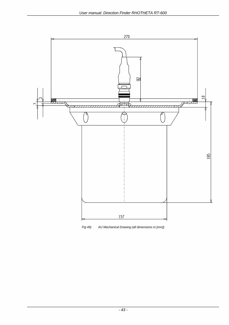
User manual Direction Finder RHOTHETA RT-600
- 43 -
Fig 49) AU Mechanical Drawing (all dimensions in [mm])
User manual Direction Finder RHOTHETA RT-600
- 44 -
6 Appendix
61 Frequency Ranges
User manual Direction Finder RHOTHETA RT-600
- 45 -
62 Frequencies of channels on maritime band (only for standard [A] version) Frequency-range of the RT-600 in the maritime band 156000 MHz 162025 MHz
Channel No frequency (ship - station) Frequency (coast - station)
1 156050 MHz 160650 MHz 2 156100 MHz 160700 MHz 3 156150 MHz 160750 MHz 4 156200 MHz 160800 MHz 5 156250 MHz 160850 MHz 6 156300 MHz 160900 MHz 7 156350 MHz 160950 MHz 8 156400 MHz 9 156450 MHz
10 156500 MHz 11 156550 MHz 12 156600 MHz 13 156650 MHz 14 156700 MHz 15 156750 MHz 16 156800 MHz 17 156850 MHz 18 156900 MHz 161500 MHz 19 156950 MHz 161550 MHz 20 157000 MHz 161600 MHz 21 157050 MHz 161650 MHz 22 157100 MHz 161700 MHz 23 157150 MHz 161750 MHz 24 157200 MHz 161800 MHz 25 157250 MHz 161850 MHz 26 157300 MHz 161900 MHz 27 157350 MHz 161950 MHz 28 157400 MHz 162000 MHz 60 156025 MHz 160625 MHz 61 156075 MHz 160675 MHz 62 156125 MHz 160725 MHz 63 156175 MHz 160775 MHz 64 156225 MHz 160825 MHz 65 156275 MHz 160875 MHz 66 156325 MHz 160925 MHz 67 156375 MHz 68 156425 MHz 69 156475 MHz 70 156525 MHz 71 156575 MHz 72 156625 MHz 73 156675 MHz 74 156725 MHz 75 156775 MHz 76 156825 MHz 77 156875 MHz 78 156925 MHz 161525 MHz 79 156975 MHz 161575 MHz 80 157025 MHz 161625 MHz 81 157075 MHz 161675 MHz 82 157125 MHz 161725 MHz 83 157175 MHz 161775 MHz 84 157225 MHz 161825 MHz 85 157275 MHz 161875 MHz 86 157325 MHz 161925 MHz 87 157375 MHz 161975 MHz 88 157425 MHz 162025 MHz
User manual Direction Finder RHOTHETA RT-600
- 46 -
63 Serial interface data protocol (short description)
631 General
Interface parameters RS232 9600 Baud 8 databits 1 stopbit no parity LSB sent first Timing of serial data For accurate use of the serial data (even for the optional serial input commands) the correct timing is mandatory The DCU (Display Control Unit) sends out via the RS-232 Pins (see 43 System Interconnect Wiring Diagram page 38) cyclic and autonomous every approx 250300 ms a binary data stream which contains all relevant DF-bearing information The output data contains one or two blocks of binary data (see next picture with accordingly description) The optional serial input is only used if changes (as example frequency change) are done by additional remote control units
Fig 50) Timing of serial data
Serial standard output
This output data is always available and contains all relevant DF-bearing data For detailed content see page 47
Optional extended serial output
This data contains some additional information like as example CospasSarsat or LoJack decoding and ID data For detailed content see page 50 The data is only available with DCU Software [Rev ge 320] and if this optional data block is configured as ON = enabled (see Setup Edit Page point (10) )
Even to avoid compatibility problems with already existing older remote control software it is possible to disable switch off this additional data block (see Setup Edit Page point (10) )
Optional serial input
Only used for optional commands to control DCU parameters If as example the direction finder frequency is changed remotely there is send to the DCU one time this data block with the new frequency For detailed content see page 52
User manual Direction Finder RHOTHETA RT-600
- 47 -
632 Serial standard output (protocol description)
Specification serial standard output
The binary data stream with a length of 39 bytes starts with a header byte (value = hex 0xA0 as ID for DF Mode) The next bytes contain different values for status bearing information and also service The last byte is used for data stream checksum control Remark This is a binary data protocol So every byte value from 0dec hellip 255dec (0x00 hellip 0xFF) is possible Because of this it is not allowed to realize a start byte detection by the content (0xA0) The idle line detection is recommended for detection the end of message Register of databytes (for details see next page)
byte no
[0] Header = 0xA0 Id for DF Mode
[1] Number = 39 = bytes in the complete message (including header and checksumbyte)
[2] Status (1) HSB [x|x|x|x|x|x|x|x] LSB | | | | | | | --gt (0) Receiving | | | | | | ----gt (1) Squelch controlled by AU (X) | | | | | ------gt (2) Permission RL Calibration | | | | --------gt (3) Line Night | | | ----------gt (4) Line NVG | | ------------gt (5) Dimming External | --------------gt (6) Autosquelch Active ----------------gt (7) 0=Standard Version 1=LE Version
[3] Status (2) HSB [x|x|x|x|x|x|x|x] LSB | ----------------gt (7) 0=Standard 1=extended serial dataprotocol = ONactive
[45] Error (Bits[120])
[6] Actual DCU Page
[7] Volume [0hellip100]
[811] Frequency [Hz]
[12] Active Band
[13] Actual Squelchlevel [0hellip60]
[14] Audio-Line amp_NF_Test Output
[15] (Not used)
[1617] Voltage_DCU ([0hellip335]=[0 hellip 335]V
[1819] Voltage_AU ([0hellip255]=[0 hellip 255]V
[20] Temperature_AU [-68hellip+127]degC
[21] Frequency Offset [-99hellip+99]
[2225] ServiceTest values (mode dependent test values for service only)
26 (Not used reserved)
[27] Level [0hellip100]
[2829] Bearing Averaged [0hellip359]deg relative
[3031] Bearing Live_Min [0hellip359]deg relative
[3233] Bearing Live_Max [0hellip359]deg relative
[34] Test Value PS-RAM Right Rotation[0hellip178] (for service only)
[35] Test Value PS-RAM Left Rotation [0hellip178] (for service only)
[3637] (Not used reserved)
[38] Checksum is the 2rsquos complement of the modulo-256 sum of all bytes without checksum-byte [0n-1]
User manual Direction Finder RHOTHETA RT-600
- 48 -
Detailed Description of important values for practical use
Status byte [2] Receiving Bit 0 of this value (LSB) indicates signal receiving Bit 0 = 0 then no signal is received and so on no bearing is available Bit 0 = 1 then bearing is possible Bit 1 if(1) then Squelch is controlled by AU (active at modes CospasSarsat Decode CospasSarsat Scanning LoJack with Filter=ID only)
Error bytes [4hellip5] 16 bit value each set bit corresponds to the error no (Refer to the chapter Error messages) Example - 0x0000 No error - 0x0800 Bit No 11 Set ( = No AU Error)
Actual DCU Page byte [6] indicates actual operating mode of DCU 0 = Standard bearing page 1 = Frequency memory page 2 = CospasSarsat decoding page 3 = LoJack decoding page (ID edit)
Frequency bytes [8hellip11] 32 bit value actual adjusted frequency [Hz] Example - 0x073DF160 1215000000 121500 MHz
Active Band Standard Version [A] 0=VHF Airband 1=VHF Marineband sea 2=VHF Marineband coast 3=UHV Airband 4=CospasSarsat LE Version [L] 0=VHF Airband 1=LoJack 2=Lifesaver 3=ETS 4=CospasSarsat
Actual Squelchlevel byte [13] Range [0hellip60] without signal the actual squelchlevel should always be adjusted a little bit over the noise level (Refer to the chapter Squelch operation)
Level byte [27] Range [099] actual receiving level (without signal this value is equal to the noise level) If a signal is received then this value corresponds to the signal strength of this signal
Relative Bearing averaged byte [2829] 16 bit value Range [0hellip359 0xFFFF] if the value = 0xFFFF then no valid bearing is available otherwise this value contains the actual averaged bearing information in Deg [0deg359deg] Example - 0X0114 276deg bearing (= left side oriented to heading)
Bearing Live MinMax byte[3031] amp [3233] - 16 bit values Range [0hellip359 0xFFFF] Only for signal quality or additional information ndash NOT recommended for bearing indication The relative live bearing field contains the maxmin bearing in degrees without averaging The relative live bearing reacts faster than the normal relative bearing but it has not the precision of the averaged bearing The MinMax Bearing Values are calculated within a time period of approx 250 ms If they are very close together (for example ldquo124rdquo and ldquo128rdquo degrees) then the signal quality is quite good A wide span of the minmax values (for example ldquo97rdquo and ldquo162rdquo) shows very noisy but nevertheless bearable signal quality
User manual Direction Finder RHOTHETA RT-600
- 49 -
633 DCU Info output (protocol description)
Specification DCU Info output
Remark This protocol is only available while the SetupEdit page is activated at the DCU
byte no
[0] Header = 0xAF Id for DCU Info Mode
[1] Number = 39 = bytes in the complete message (including header and checksumbyte)
[2]
(see standard output) [3]
[45]
[621] Info String of 15 byteschars the string contains Information about Unit Variant Software Version and Serial No
Example Byte [318] =
|--AU ID---||Var-||---Software Version---| |-------------- Serial No---------------| [0x44][0x55][0x41][0x33][0x2E][0x33][0x30][0x3A][0x20][0x20][0x30][0x31][0x32][0x33][0x34][0x00] rsquoDrsquo rsquoUrsquo rsquoArsquo rsquo3rsquo rsquorsquo rsquo3rsquo rsquo0rsquo rsquorsquo rsquo rsquo rsquo rsquo rsquo0rsquo rsquo1rsquo rsquo2rsquo rsquo3rsquo rsquo4rsquo rsquoENDrsquo | | | | __________________ | | ________________________ | n n n | | n n n n n | (Software Version) | | (Serial No) | gt rsquoArsquo = Standard Variant gt rsquoLrsquo = Law Enforcement Variant
User manual Direction Finder RHOTHETA RT-600
- 50 -
634 Optional extended serial output (protocol description)
The data content depends on the actual mode of the direction finder To get special data the direction finder has first to be switched to the equivalent mode
COSPAS-SARSAT Decoding data
This data is only available and valid if Display Control Unit with actual software Rev ge 320 (see Power-On procedure page 10) Configuration of Extended serial = ON (see Setup Edit Page point (10) ) Direction Finder COSPAS-SARSAT decoding mode is activated by selecting the corresponding page
(see COSPAS-SARSAT Decode Window page 20 and page 21) and so on Header (byte 0 of data) = 0x91
A valid COSPAS-SARSAT decoding data protocol is always marked by the first data byte (header = 0x91) Always after receiving and decoding of a valid COSPAS-SARSAT pulse the complete data protocol with 33 bytes is send out one time
Byte No
[0] Header = 0x91 (Identification for CPSarsat decoding mode)
[1] Number of bytes - 7 if no decoded pulse is available - 33 if new pulse was received and is available
[2] Error
[3] Bit[0] - 0 =gt No new 406 MSG (decoded data) available - 1 =gt New valid 406 MSG available (Sync amp Frame Ok) Check Error Status for Bit-Errors
Bit[61] AutoSquelch Level valid range [060] ( decimal)
Bit[7] = 1 Squelch controlled by AU
[4] Signallevel of received signal valid range [099] ( decimal)
[5] Voltage of Antenna Unit Power Supply input valid range [80255] (decimal = 80 255 V DC)
[6] Temperature inside Antenna Unit valid range [-50+100] (degC signed byte value)
The following databytes are only available if a correct CPSarsat puls gets received and decoded with correct checksum
[724] 18 x Databytes complete orginal CPSarsat 406 decoded message (144 bit)
Databyte Nr [ Byte 7 ] [ Byte 8 ] [Byte9 Byte24] 406 MSG Bit Nr [1 2 3 4 5 6 7 8] [9 10 11 12 13 14 15 16] [17 144]
[25] SN-Flag valid values 0x53=rsquoSrsquo 0x4E=rsquoNrsquo 0x2D=rsquo-rsquo if no GPS data available
GPS-Position Latitude
[26] Deg valid values [090] (decimal Deg) 0xFF if no GPS data available
[27] Min valid values [059] (decimal Deg) 0xFF if no GPS data available
[28] Sec valid values [059] (decimal Deg) 0xFF if no GPS data available
[29] WE-Flag valid values 0x57=rsquoWrsquo 0x45=rsquoErsquo 0x2D=rsquo-rsquo if no GPS data available
GPS-Position Longitude
[30] Deg valid values [0180] (decimal Deg) 0xFF if no GPS data available
[31] Min valid values [059] (decimal Deg) 0xFF if no GPS data available
[32] Sec valid values [059] (decimal Deg) 0xFF if no GPS data available
User manual Direction Finder RHOTHETA RT-600
- 51 -
LoJack ID data
This data is only available and valid if Display Control Unit with actual software Rev ge 320 (see Power-On procedure page 10) Direction Finder of variant [L] Law Enforcement Configuration of Extended serial = ON (see Setup Edit Page point (10) ) Direction Finder is working with active LoJack gtID Filterlt Header (byte 0 of data) = 0x93 or 0x94
Valid LoJack ID decoding data is always marked by the first data byte (header = 0x93 or 0x94)
Byte No
[0] Header = 0x93 LoJack ID editing sub-page is selected Filter = VLU all valid and received LoJack pulses are indicated = 0x94 Lojack Decode amp DF Mode with active Filter = ID
[1] Number of bytes in the complete data stream - decimal 26 = default value
[2] Nonrelevant
[3] Bit[0] Receiving OnOff - 0 =gt No Receiving no bearing - 1 =gt new LoJack pulse received
[412] Nonrelevant
[1317] Lojack ID
Replay Code 5 x ASCII Chars ldquoNo BIOZrdquo set
Example ASCII = ldquo000R1rdquo
18 Receiver Level Out Max [099]
19
LoJack Decoder Status [07] - 0 Off - 1 Wait for Preamble - 2 Preamble Ok - 3 FlagPattern Ok - 4 Data BitError gt 1 - 5 Data Ok (No VLU) - 6 VLU Ok - 7 ID Ok (Filter=IDONLY)
[2025] Nonrelevant
Remark Only if byte no [3] bit [0] gets ldquo1rdquo (Receiving On) then an active LoJack pulse is received and so on the corresponding LoJack ID valid otherwise the LoJack ID only shows the actual adjusted LoJack Filter ID of the direction finder
User manual Direction Finder RHOTHETA RT-600
- 52 -
635 Optional serial input (protocol description)
Specification serial input (optional)
The serial input is normally used for service and maintenance only Nevertheless it is possible via this interface to remote control the actual frequency and the squelchlevel of the DF system If a valid data stream is send to the DF then the actual frequency selection at the DCU is switched to Block2 AUX0 At this memory channel the new frequency is stored and used automatically (Refer to the chapter Frequency Selection Page) If the frequency is changed (by one valid data stream) no more serial input is necessary The actual frequency can be changed again at any time by manual operation at the DCU The timing of serial input (if used) is strictly fixed The optional serial input has to take place directly after a complete serial output (max 50 ms delay time) If a new changed frequency is commanded to the DCU via this serial input interface it can take up to 1 sec of time until this new frequency is ready for operationbearing It is strictly not recommended to use the frequency remote control for any scan mode The frequency control has to be used for static frequency change only Register of databytes
byte no
[0] Header 0xC0
[1] Number of bytes in the complete message (including header and checksumbyte)
[23] (not used for normal operation any byte values allowed)
[4] Volume [0100]
[58] Frequency [Hz] (frequency is rounded to the according grid automatically)
Valid Range for Standard Version Valid Range for LE Version
118000000 hellip 123000000 [Hz] 8333 kHz 118000000 hellip 123000000 [Hz] 8333 kHz
156050000 hellip 162025000 [Hz] 5000 kHz 164000000 hellip 174000000 [Hz] 8333 kHz
201000000 hellip 215995000 [Hz] 5000 kHz
240000000 hellip 246000000 [Hz] 8333 kHz 216000000 hellip 218995000 [Hz] 12500 kHz219000000 hellip 220000000 [Hz] 10000 kHz
400000000 hellip 410000000 [Hz] 8333 kHz 400000000 hellip 410000000 [Hz] 8333 kHz
[9] Squelchlevel Manual = [0hellip60] Autosql= [ -1] Warning use only for pulsed signals (as example CpSarsat LoJack)
[10] (not used for normal operation any byte values allowed)
[11] Internal Dimming [0100]
[12] Checksum is the 2rsquos complement of the modulo-256 sum of all bytes without checksum-byte [0n-1]
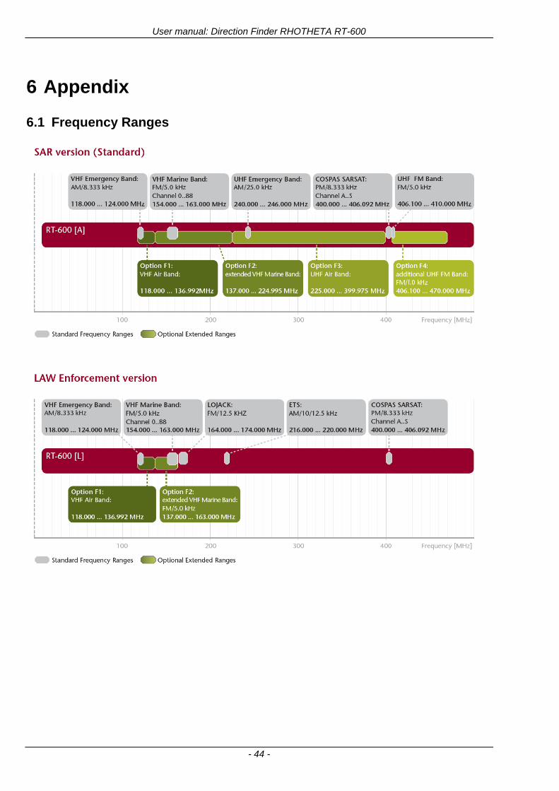
User manual Direction Finder RHOTHETA RT-600
- 44 -
6 Appendix
61 Frequency Ranges
User manual Direction Finder RHOTHETA RT-600
- 45 -
62 Frequencies of channels on maritime band (only for standard [A] version) Frequency-range of the RT-600 in the maritime band 156000 MHz 162025 MHz
Channel No frequency (ship - station) Frequency (coast - station)
1 156050 MHz 160650 MHz 2 156100 MHz 160700 MHz 3 156150 MHz 160750 MHz 4 156200 MHz 160800 MHz 5 156250 MHz 160850 MHz 6 156300 MHz 160900 MHz 7 156350 MHz 160950 MHz 8 156400 MHz 9 156450 MHz
10 156500 MHz 11 156550 MHz 12 156600 MHz 13 156650 MHz 14 156700 MHz 15 156750 MHz 16 156800 MHz 17 156850 MHz 18 156900 MHz 161500 MHz 19 156950 MHz 161550 MHz 20 157000 MHz 161600 MHz 21 157050 MHz 161650 MHz 22 157100 MHz 161700 MHz 23 157150 MHz 161750 MHz 24 157200 MHz 161800 MHz 25 157250 MHz 161850 MHz 26 157300 MHz 161900 MHz 27 157350 MHz 161950 MHz 28 157400 MHz 162000 MHz 60 156025 MHz 160625 MHz 61 156075 MHz 160675 MHz 62 156125 MHz 160725 MHz 63 156175 MHz 160775 MHz 64 156225 MHz 160825 MHz 65 156275 MHz 160875 MHz 66 156325 MHz 160925 MHz 67 156375 MHz 68 156425 MHz 69 156475 MHz 70 156525 MHz 71 156575 MHz 72 156625 MHz 73 156675 MHz 74 156725 MHz 75 156775 MHz 76 156825 MHz 77 156875 MHz 78 156925 MHz 161525 MHz 79 156975 MHz 161575 MHz 80 157025 MHz 161625 MHz 81 157075 MHz 161675 MHz 82 157125 MHz 161725 MHz 83 157175 MHz 161775 MHz 84 157225 MHz 161825 MHz 85 157275 MHz 161875 MHz 86 157325 MHz 161925 MHz 87 157375 MHz 161975 MHz 88 157425 MHz 162025 MHz
User manual Direction Finder RHOTHETA RT-600
- 46 -
63 Serial interface data protocol (short description)
631 General
Interface parameters RS232 9600 Baud 8 databits 1 stopbit no parity LSB sent first Timing of serial data For accurate use of the serial data (even for the optional serial input commands) the correct timing is mandatory The DCU (Display Control Unit) sends out via the RS-232 Pins (see 43 System Interconnect Wiring Diagram page 38) cyclic and autonomous every approx 250300 ms a binary data stream which contains all relevant DF-bearing information The output data contains one or two blocks of binary data (see next picture with accordingly description) The optional serial input is only used if changes (as example frequency change) are done by additional remote control units
Fig 50) Timing of serial data
Serial standard output
This output data is always available and contains all relevant DF-bearing data For detailed content see page 47
Optional extended serial output
This data contains some additional information like as example CospasSarsat or LoJack decoding and ID data For detailed content see page 50 The data is only available with DCU Software [Rev ge 320] and if this optional data block is configured as ON = enabled (see Setup Edit Page point (10) )
Even to avoid compatibility problems with already existing older remote control software it is possible to disable switch off this additional data block (see Setup Edit Page point (10) )
Optional serial input
Only used for optional commands to control DCU parameters If as example the direction finder frequency is changed remotely there is send to the DCU one time this data block with the new frequency For detailed content see page 52
User manual Direction Finder RHOTHETA RT-600
- 47 -
632 Serial standard output (protocol description)
Specification serial standard output
The binary data stream with a length of 39 bytes starts with a header byte (value = hex 0xA0 as ID for DF Mode) The next bytes contain different values for status bearing information and also service The last byte is used for data stream checksum control Remark This is a binary data protocol So every byte value from 0dec hellip 255dec (0x00 hellip 0xFF) is possible Because of this it is not allowed to realize a start byte detection by the content (0xA0) The idle line detection is recommended for detection the end of message Register of databytes (for details see next page)
byte no
[0] Header = 0xA0 Id for DF Mode
[1] Number = 39 = bytes in the complete message (including header and checksumbyte)
[2] Status (1) HSB [x|x|x|x|x|x|x|x] LSB | | | | | | | --gt (0) Receiving | | | | | | ----gt (1) Squelch controlled by AU (X) | | | | | ------gt (2) Permission RL Calibration | | | | --------gt (3) Line Night | | | ----------gt (4) Line NVG | | ------------gt (5) Dimming External | --------------gt (6) Autosquelch Active ----------------gt (7) 0=Standard Version 1=LE Version
[3] Status (2) HSB [x|x|x|x|x|x|x|x] LSB | ----------------gt (7) 0=Standard 1=extended serial dataprotocol = ONactive
[45] Error (Bits[120])
[6] Actual DCU Page
[7] Volume [0hellip100]
[811] Frequency [Hz]
[12] Active Band
[13] Actual Squelchlevel [0hellip60]
[14] Audio-Line amp_NF_Test Output
[15] (Not used)
[1617] Voltage_DCU ([0hellip335]=[0 hellip 335]V
[1819] Voltage_AU ([0hellip255]=[0 hellip 255]V
[20] Temperature_AU [-68hellip+127]degC
[21] Frequency Offset [-99hellip+99]
[2225] ServiceTest values (mode dependent test values for service only)
26 (Not used reserved)
[27] Level [0hellip100]
[2829] Bearing Averaged [0hellip359]deg relative
[3031] Bearing Live_Min [0hellip359]deg relative
[3233] Bearing Live_Max [0hellip359]deg relative
[34] Test Value PS-RAM Right Rotation[0hellip178] (for service only)
[35] Test Value PS-RAM Left Rotation [0hellip178] (for service only)
[3637] (Not used reserved)
[38] Checksum is the 2rsquos complement of the modulo-256 sum of all bytes without checksum-byte [0n-1]
User manual Direction Finder RHOTHETA RT-600
- 48 -
Detailed Description of important values for practical use
Status byte [2] Receiving Bit 0 of this value (LSB) indicates signal receiving Bit 0 = 0 then no signal is received and so on no bearing is available Bit 0 = 1 then bearing is possible Bit 1 if(1) then Squelch is controlled by AU (active at modes CospasSarsat Decode CospasSarsat Scanning LoJack with Filter=ID only)
Error bytes [4hellip5] 16 bit value each set bit corresponds to the error no (Refer to the chapter Error messages) Example - 0x0000 No error - 0x0800 Bit No 11 Set ( = No AU Error)
Actual DCU Page byte [6] indicates actual operating mode of DCU 0 = Standard bearing page 1 = Frequency memory page 2 = CospasSarsat decoding page 3 = LoJack decoding page (ID edit)
Frequency bytes [8hellip11] 32 bit value actual adjusted frequency [Hz] Example - 0x073DF160 1215000000 121500 MHz
Active Band Standard Version [A] 0=VHF Airband 1=VHF Marineband sea 2=VHF Marineband coast 3=UHV Airband 4=CospasSarsat LE Version [L] 0=VHF Airband 1=LoJack 2=Lifesaver 3=ETS 4=CospasSarsat
Actual Squelchlevel byte [13] Range [0hellip60] without signal the actual squelchlevel should always be adjusted a little bit over the noise level (Refer to the chapter Squelch operation)
Level byte [27] Range [099] actual receiving level (without signal this value is equal to the noise level) If a signal is received then this value corresponds to the signal strength of this signal
Relative Bearing averaged byte [2829] 16 bit value Range [0hellip359 0xFFFF] if the value = 0xFFFF then no valid bearing is available otherwise this value contains the actual averaged bearing information in Deg [0deg359deg] Example - 0X0114 276deg bearing (= left side oriented to heading)
Bearing Live MinMax byte[3031] amp [3233] - 16 bit values Range [0hellip359 0xFFFF] Only for signal quality or additional information ndash NOT recommended for bearing indication The relative live bearing field contains the maxmin bearing in degrees without averaging The relative live bearing reacts faster than the normal relative bearing but it has not the precision of the averaged bearing The MinMax Bearing Values are calculated within a time period of approx 250 ms If they are very close together (for example ldquo124rdquo and ldquo128rdquo degrees) then the signal quality is quite good A wide span of the minmax values (for example ldquo97rdquo and ldquo162rdquo) shows very noisy but nevertheless bearable signal quality
User manual Direction Finder RHOTHETA RT-600
- 49 -
633 DCU Info output (protocol description)
Specification DCU Info output
Remark This protocol is only available while the SetupEdit page is activated at the DCU
byte no
[0] Header = 0xAF Id for DCU Info Mode
[1] Number = 39 = bytes in the complete message (including header and checksumbyte)
[2]
(see standard output) [3]
[45]
[621] Info String of 15 byteschars the string contains Information about Unit Variant Software Version and Serial No
Example Byte [318] =
|--AU ID---||Var-||---Software Version---| |-------------- Serial No---------------| [0x44][0x55][0x41][0x33][0x2E][0x33][0x30][0x3A][0x20][0x20][0x30][0x31][0x32][0x33][0x34][0x00] rsquoDrsquo rsquoUrsquo rsquoArsquo rsquo3rsquo rsquorsquo rsquo3rsquo rsquo0rsquo rsquorsquo rsquo rsquo rsquo rsquo rsquo0rsquo rsquo1rsquo rsquo2rsquo rsquo3rsquo rsquo4rsquo rsquoENDrsquo | | | | __________________ | | ________________________ | n n n | | n n n n n | (Software Version) | | (Serial No) | gt rsquoArsquo = Standard Variant gt rsquoLrsquo = Law Enforcement Variant
User manual Direction Finder RHOTHETA RT-600
- 50 -
634 Optional extended serial output (protocol description)
The data content depends on the actual mode of the direction finder To get special data the direction finder has first to be switched to the equivalent mode
COSPAS-SARSAT Decoding data
This data is only available and valid if Display Control Unit with actual software Rev ge 320 (see Power-On procedure page 10) Configuration of Extended serial = ON (see Setup Edit Page point (10) ) Direction Finder COSPAS-SARSAT decoding mode is activated by selecting the corresponding page
(see COSPAS-SARSAT Decode Window page 20 and page 21) and so on Header (byte 0 of data) = 0x91
A valid COSPAS-SARSAT decoding data protocol is always marked by the first data byte (header = 0x91) Always after receiving and decoding of a valid COSPAS-SARSAT pulse the complete data protocol with 33 bytes is send out one time
Byte No
[0] Header = 0x91 (Identification for CPSarsat decoding mode)
[1] Number of bytes - 7 if no decoded pulse is available - 33 if new pulse was received and is available
[2] Error
[3] Bit[0] - 0 =gt No new 406 MSG (decoded data) available - 1 =gt New valid 406 MSG available (Sync amp Frame Ok) Check Error Status for Bit-Errors
Bit[61] AutoSquelch Level valid range [060] ( decimal)
Bit[7] = 1 Squelch controlled by AU
[4] Signallevel of received signal valid range [099] ( decimal)
[5] Voltage of Antenna Unit Power Supply input valid range [80255] (decimal = 80 255 V DC)
[6] Temperature inside Antenna Unit valid range [-50+100] (degC signed byte value)
The following databytes are only available if a correct CPSarsat puls gets received and decoded with correct checksum
[724] 18 x Databytes complete orginal CPSarsat 406 decoded message (144 bit)
Databyte Nr [ Byte 7 ] [ Byte 8 ] [Byte9 Byte24] 406 MSG Bit Nr [1 2 3 4 5 6 7 8] [9 10 11 12 13 14 15 16] [17 144]
[25] SN-Flag valid values 0x53=rsquoSrsquo 0x4E=rsquoNrsquo 0x2D=rsquo-rsquo if no GPS data available
GPS-Position Latitude
[26] Deg valid values [090] (decimal Deg) 0xFF if no GPS data available
[27] Min valid values [059] (decimal Deg) 0xFF if no GPS data available
[28] Sec valid values [059] (decimal Deg) 0xFF if no GPS data available
[29] WE-Flag valid values 0x57=rsquoWrsquo 0x45=rsquoErsquo 0x2D=rsquo-rsquo if no GPS data available
GPS-Position Longitude
[30] Deg valid values [0180] (decimal Deg) 0xFF if no GPS data available
[31] Min valid values [059] (decimal Deg) 0xFF if no GPS data available
[32] Sec valid values [059] (decimal Deg) 0xFF if no GPS data available
User manual Direction Finder RHOTHETA RT-600
- 51 -
LoJack ID data
This data is only available and valid if Display Control Unit with actual software Rev ge 320 (see Power-On procedure page 10) Direction Finder of variant [L] Law Enforcement Configuration of Extended serial = ON (see Setup Edit Page point (10) ) Direction Finder is working with active LoJack gtID Filterlt Header (byte 0 of data) = 0x93 or 0x94
Valid LoJack ID decoding data is always marked by the first data byte (header = 0x93 or 0x94)
Byte No
[0] Header = 0x93 LoJack ID editing sub-page is selected Filter = VLU all valid and received LoJack pulses are indicated = 0x94 Lojack Decode amp DF Mode with active Filter = ID
[1] Number of bytes in the complete data stream - decimal 26 = default value
[2] Nonrelevant
[3] Bit[0] Receiving OnOff - 0 =gt No Receiving no bearing - 1 =gt new LoJack pulse received
[412] Nonrelevant
[1317] Lojack ID
Replay Code 5 x ASCII Chars ldquoNo BIOZrdquo set
Example ASCII = ldquo000R1rdquo
18 Receiver Level Out Max [099]
19
LoJack Decoder Status [07] - 0 Off - 1 Wait for Preamble - 2 Preamble Ok - 3 FlagPattern Ok - 4 Data BitError gt 1 - 5 Data Ok (No VLU) - 6 VLU Ok - 7 ID Ok (Filter=IDONLY)
[2025] Nonrelevant
Remark Only if byte no [3] bit [0] gets ldquo1rdquo (Receiving On) then an active LoJack pulse is received and so on the corresponding LoJack ID valid otherwise the LoJack ID only shows the actual adjusted LoJack Filter ID of the direction finder
User manual Direction Finder RHOTHETA RT-600
- 52 -
635 Optional serial input (protocol description)
Specification serial input (optional)
The serial input is normally used for service and maintenance only Nevertheless it is possible via this interface to remote control the actual frequency and the squelchlevel of the DF system If a valid data stream is send to the DF then the actual frequency selection at the DCU is switched to Block2 AUX0 At this memory channel the new frequency is stored and used automatically (Refer to the chapter Frequency Selection Page) If the frequency is changed (by one valid data stream) no more serial input is necessary The actual frequency can be changed again at any time by manual operation at the DCU The timing of serial input (if used) is strictly fixed The optional serial input has to take place directly after a complete serial output (max 50 ms delay time) If a new changed frequency is commanded to the DCU via this serial input interface it can take up to 1 sec of time until this new frequency is ready for operationbearing It is strictly not recommended to use the frequency remote control for any scan mode The frequency control has to be used for static frequency change only Register of databytes
byte no
[0] Header 0xC0
[1] Number of bytes in the complete message (including header and checksumbyte)
[23] (not used for normal operation any byte values allowed)
[4] Volume [0100]
[58] Frequency [Hz] (frequency is rounded to the according grid automatically)
Valid Range for Standard Version Valid Range for LE Version
118000000 hellip 123000000 [Hz] 8333 kHz 118000000 hellip 123000000 [Hz] 8333 kHz
156050000 hellip 162025000 [Hz] 5000 kHz 164000000 hellip 174000000 [Hz] 8333 kHz
201000000 hellip 215995000 [Hz] 5000 kHz
240000000 hellip 246000000 [Hz] 8333 kHz 216000000 hellip 218995000 [Hz] 12500 kHz219000000 hellip 220000000 [Hz] 10000 kHz
400000000 hellip 410000000 [Hz] 8333 kHz 400000000 hellip 410000000 [Hz] 8333 kHz
[9] Squelchlevel Manual = [0hellip60] Autosql= [ -1] Warning use only for pulsed signals (as example CpSarsat LoJack)
[10] (not used for normal operation any byte values allowed)
[11] Internal Dimming [0100]
[12] Checksum is the 2rsquos complement of the modulo-256 sum of all bytes without checksum-byte [0n-1]
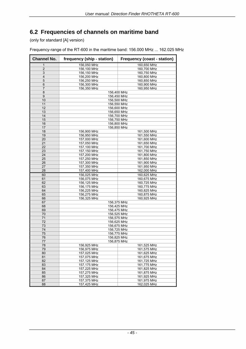
User manual Direction Finder RHOTHETA RT-600
- 45 -
62 Frequencies of channels on maritime band (only for standard [A] version) Frequency-range of the RT-600 in the maritime band 156000 MHz 162025 MHz
Channel No frequency (ship - station) Frequency (coast - station)
1 156050 MHz 160650 MHz 2 156100 MHz 160700 MHz 3 156150 MHz 160750 MHz 4 156200 MHz 160800 MHz 5 156250 MHz 160850 MHz 6 156300 MHz 160900 MHz 7 156350 MHz 160950 MHz 8 156400 MHz 9 156450 MHz
10 156500 MHz 11 156550 MHz 12 156600 MHz 13 156650 MHz 14 156700 MHz 15 156750 MHz 16 156800 MHz 17 156850 MHz 18 156900 MHz 161500 MHz 19 156950 MHz 161550 MHz 20 157000 MHz 161600 MHz 21 157050 MHz 161650 MHz 22 157100 MHz 161700 MHz 23 157150 MHz 161750 MHz 24 157200 MHz 161800 MHz 25 157250 MHz 161850 MHz 26 157300 MHz 161900 MHz 27 157350 MHz 161950 MHz 28 157400 MHz 162000 MHz 60 156025 MHz 160625 MHz 61 156075 MHz 160675 MHz 62 156125 MHz 160725 MHz 63 156175 MHz 160775 MHz 64 156225 MHz 160825 MHz 65 156275 MHz 160875 MHz 66 156325 MHz 160925 MHz 67 156375 MHz 68 156425 MHz 69 156475 MHz 70 156525 MHz 71 156575 MHz 72 156625 MHz 73 156675 MHz 74 156725 MHz 75 156775 MHz 76 156825 MHz 77 156875 MHz 78 156925 MHz 161525 MHz 79 156975 MHz 161575 MHz 80 157025 MHz 161625 MHz 81 157075 MHz 161675 MHz 82 157125 MHz 161725 MHz 83 157175 MHz 161775 MHz 84 157225 MHz 161825 MHz 85 157275 MHz 161875 MHz 86 157325 MHz 161925 MHz 87 157375 MHz 161975 MHz 88 157425 MHz 162025 MHz
User manual Direction Finder RHOTHETA RT-600
- 46 -
63 Serial interface data protocol (short description)
631 General
Interface parameters RS232 9600 Baud 8 databits 1 stopbit no parity LSB sent first Timing of serial data For accurate use of the serial data (even for the optional serial input commands) the correct timing is mandatory The DCU (Display Control Unit) sends out via the RS-232 Pins (see 43 System Interconnect Wiring Diagram page 38) cyclic and autonomous every approx 250300 ms a binary data stream which contains all relevant DF-bearing information The output data contains one or two blocks of binary data (see next picture with accordingly description) The optional serial input is only used if changes (as example frequency change) are done by additional remote control units
Fig 50) Timing of serial data
Serial standard output
This output data is always available and contains all relevant DF-bearing data For detailed content see page 47
Optional extended serial output
This data contains some additional information like as example CospasSarsat or LoJack decoding and ID data For detailed content see page 50 The data is only available with DCU Software [Rev ge 320] and if this optional data block is configured as ON = enabled (see Setup Edit Page point (10) )
Even to avoid compatibility problems with already existing older remote control software it is possible to disable switch off this additional data block (see Setup Edit Page point (10) )
Optional serial input
Only used for optional commands to control DCU parameters If as example the direction finder frequency is changed remotely there is send to the DCU one time this data block with the new frequency For detailed content see page 52
User manual Direction Finder RHOTHETA RT-600
- 47 -
632 Serial standard output (protocol description)
Specification serial standard output
The binary data stream with a length of 39 bytes starts with a header byte (value = hex 0xA0 as ID for DF Mode) The next bytes contain different values for status bearing information and also service The last byte is used for data stream checksum control Remark This is a binary data protocol So every byte value from 0dec hellip 255dec (0x00 hellip 0xFF) is possible Because of this it is not allowed to realize a start byte detection by the content (0xA0) The idle line detection is recommended for detection the end of message Register of databytes (for details see next page)
byte no
[0] Header = 0xA0 Id for DF Mode
[1] Number = 39 = bytes in the complete message (including header and checksumbyte)
[2] Status (1) HSB [x|x|x|x|x|x|x|x] LSB | | | | | | | --gt (0) Receiving | | | | | | ----gt (1) Squelch controlled by AU (X) | | | | | ------gt (2) Permission RL Calibration | | | | --------gt (3) Line Night | | | ----------gt (4) Line NVG | | ------------gt (5) Dimming External | --------------gt (6) Autosquelch Active ----------------gt (7) 0=Standard Version 1=LE Version
[3] Status (2) HSB [x|x|x|x|x|x|x|x] LSB | ----------------gt (7) 0=Standard 1=extended serial dataprotocol = ONactive
[45] Error (Bits[120])
[6] Actual DCU Page
[7] Volume [0hellip100]
[811] Frequency [Hz]
[12] Active Band
[13] Actual Squelchlevel [0hellip60]
[14] Audio-Line amp_NF_Test Output
[15] (Not used)
[1617] Voltage_DCU ([0hellip335]=[0 hellip 335]V
[1819] Voltage_AU ([0hellip255]=[0 hellip 255]V
[20] Temperature_AU [-68hellip+127]degC
[21] Frequency Offset [-99hellip+99]
[2225] ServiceTest values (mode dependent test values for service only)
26 (Not used reserved)
[27] Level [0hellip100]
[2829] Bearing Averaged [0hellip359]deg relative
[3031] Bearing Live_Min [0hellip359]deg relative
[3233] Bearing Live_Max [0hellip359]deg relative
[34] Test Value PS-RAM Right Rotation[0hellip178] (for service only)
[35] Test Value PS-RAM Left Rotation [0hellip178] (for service only)
[3637] (Not used reserved)
[38] Checksum is the 2rsquos complement of the modulo-256 sum of all bytes without checksum-byte [0n-1]
User manual Direction Finder RHOTHETA RT-600
- 48 -
Detailed Description of important values for practical use
Status byte [2] Receiving Bit 0 of this value (LSB) indicates signal receiving Bit 0 = 0 then no signal is received and so on no bearing is available Bit 0 = 1 then bearing is possible Bit 1 if(1) then Squelch is controlled by AU (active at modes CospasSarsat Decode CospasSarsat Scanning LoJack with Filter=ID only)
Error bytes [4hellip5] 16 bit value each set bit corresponds to the error no (Refer to the chapter Error messages) Example - 0x0000 No error - 0x0800 Bit No 11 Set ( = No AU Error)
Actual DCU Page byte [6] indicates actual operating mode of DCU 0 = Standard bearing page 1 = Frequency memory page 2 = CospasSarsat decoding page 3 = LoJack decoding page (ID edit)
Frequency bytes [8hellip11] 32 bit value actual adjusted frequency [Hz] Example - 0x073DF160 1215000000 121500 MHz
Active Band Standard Version [A] 0=VHF Airband 1=VHF Marineband sea 2=VHF Marineband coast 3=UHV Airband 4=CospasSarsat LE Version [L] 0=VHF Airband 1=LoJack 2=Lifesaver 3=ETS 4=CospasSarsat
Actual Squelchlevel byte [13] Range [0hellip60] without signal the actual squelchlevel should always be adjusted a little bit over the noise level (Refer to the chapter Squelch operation)
Level byte [27] Range [099] actual receiving level (without signal this value is equal to the noise level) If a signal is received then this value corresponds to the signal strength of this signal
Relative Bearing averaged byte [2829] 16 bit value Range [0hellip359 0xFFFF] if the value = 0xFFFF then no valid bearing is available otherwise this value contains the actual averaged bearing information in Deg [0deg359deg] Example - 0X0114 276deg bearing (= left side oriented to heading)
Bearing Live MinMax byte[3031] amp [3233] - 16 bit values Range [0hellip359 0xFFFF] Only for signal quality or additional information ndash NOT recommended for bearing indication The relative live bearing field contains the maxmin bearing in degrees without averaging The relative live bearing reacts faster than the normal relative bearing but it has not the precision of the averaged bearing The MinMax Bearing Values are calculated within a time period of approx 250 ms If they are very close together (for example ldquo124rdquo and ldquo128rdquo degrees) then the signal quality is quite good A wide span of the minmax values (for example ldquo97rdquo and ldquo162rdquo) shows very noisy but nevertheless bearable signal quality
User manual Direction Finder RHOTHETA RT-600
- 49 -
633 DCU Info output (protocol description)
Specification DCU Info output
Remark This protocol is only available while the SetupEdit page is activated at the DCU
byte no
[0] Header = 0xAF Id for DCU Info Mode
[1] Number = 39 = bytes in the complete message (including header and checksumbyte)
[2]
(see standard output) [3]
[45]
[621] Info String of 15 byteschars the string contains Information about Unit Variant Software Version and Serial No
Example Byte [318] =
|--AU ID---||Var-||---Software Version---| |-------------- Serial No---------------| [0x44][0x55][0x41][0x33][0x2E][0x33][0x30][0x3A][0x20][0x20][0x30][0x31][0x32][0x33][0x34][0x00] rsquoDrsquo rsquoUrsquo rsquoArsquo rsquo3rsquo rsquorsquo rsquo3rsquo rsquo0rsquo rsquorsquo rsquo rsquo rsquo rsquo rsquo0rsquo rsquo1rsquo rsquo2rsquo rsquo3rsquo rsquo4rsquo rsquoENDrsquo | | | | __________________ | | ________________________ | n n n | | n n n n n | (Software Version) | | (Serial No) | gt rsquoArsquo = Standard Variant gt rsquoLrsquo = Law Enforcement Variant
User manual Direction Finder RHOTHETA RT-600
- 50 -
634 Optional extended serial output (protocol description)
The data content depends on the actual mode of the direction finder To get special data the direction finder has first to be switched to the equivalent mode
COSPAS-SARSAT Decoding data
This data is only available and valid if Display Control Unit with actual software Rev ge 320 (see Power-On procedure page 10) Configuration of Extended serial = ON (see Setup Edit Page point (10) ) Direction Finder COSPAS-SARSAT decoding mode is activated by selecting the corresponding page
(see COSPAS-SARSAT Decode Window page 20 and page 21) and so on Header (byte 0 of data) = 0x91
A valid COSPAS-SARSAT decoding data protocol is always marked by the first data byte (header = 0x91) Always after receiving and decoding of a valid COSPAS-SARSAT pulse the complete data protocol with 33 bytes is send out one time
Byte No
[0] Header = 0x91 (Identification for CPSarsat decoding mode)
[1] Number of bytes - 7 if no decoded pulse is available - 33 if new pulse was received and is available
[2] Error
[3] Bit[0] - 0 =gt No new 406 MSG (decoded data) available - 1 =gt New valid 406 MSG available (Sync amp Frame Ok) Check Error Status for Bit-Errors
Bit[61] AutoSquelch Level valid range [060] ( decimal)
Bit[7] = 1 Squelch controlled by AU
[4] Signallevel of received signal valid range [099] ( decimal)
[5] Voltage of Antenna Unit Power Supply input valid range [80255] (decimal = 80 255 V DC)
[6] Temperature inside Antenna Unit valid range [-50+100] (degC signed byte value)
The following databytes are only available if a correct CPSarsat puls gets received and decoded with correct checksum
[724] 18 x Databytes complete orginal CPSarsat 406 decoded message (144 bit)
Databyte Nr [ Byte 7 ] [ Byte 8 ] [Byte9 Byte24] 406 MSG Bit Nr [1 2 3 4 5 6 7 8] [9 10 11 12 13 14 15 16] [17 144]
[25] SN-Flag valid values 0x53=rsquoSrsquo 0x4E=rsquoNrsquo 0x2D=rsquo-rsquo if no GPS data available
GPS-Position Latitude
[26] Deg valid values [090] (decimal Deg) 0xFF if no GPS data available
[27] Min valid values [059] (decimal Deg) 0xFF if no GPS data available
[28] Sec valid values [059] (decimal Deg) 0xFF if no GPS data available
[29] WE-Flag valid values 0x57=rsquoWrsquo 0x45=rsquoErsquo 0x2D=rsquo-rsquo if no GPS data available
GPS-Position Longitude
[30] Deg valid values [0180] (decimal Deg) 0xFF if no GPS data available
[31] Min valid values [059] (decimal Deg) 0xFF if no GPS data available
[32] Sec valid values [059] (decimal Deg) 0xFF if no GPS data available
User manual Direction Finder RHOTHETA RT-600
- 51 -
LoJack ID data
This data is only available and valid if Display Control Unit with actual software Rev ge 320 (see Power-On procedure page 10) Direction Finder of variant [L] Law Enforcement Configuration of Extended serial = ON (see Setup Edit Page point (10) ) Direction Finder is working with active LoJack gtID Filterlt Header (byte 0 of data) = 0x93 or 0x94
Valid LoJack ID decoding data is always marked by the first data byte (header = 0x93 or 0x94)
Byte No
[0] Header = 0x93 LoJack ID editing sub-page is selected Filter = VLU all valid and received LoJack pulses are indicated = 0x94 Lojack Decode amp DF Mode with active Filter = ID
[1] Number of bytes in the complete data stream - decimal 26 = default value
[2] Nonrelevant
[3] Bit[0] Receiving OnOff - 0 =gt No Receiving no bearing - 1 =gt new LoJack pulse received
[412] Nonrelevant
[1317] Lojack ID
Replay Code 5 x ASCII Chars ldquoNo BIOZrdquo set
Example ASCII = ldquo000R1rdquo
18 Receiver Level Out Max [099]
19
LoJack Decoder Status [07] - 0 Off - 1 Wait for Preamble - 2 Preamble Ok - 3 FlagPattern Ok - 4 Data BitError gt 1 - 5 Data Ok (No VLU) - 6 VLU Ok - 7 ID Ok (Filter=IDONLY)
[2025] Nonrelevant
Remark Only if byte no [3] bit [0] gets ldquo1rdquo (Receiving On) then an active LoJack pulse is received and so on the corresponding LoJack ID valid otherwise the LoJack ID only shows the actual adjusted LoJack Filter ID of the direction finder
User manual Direction Finder RHOTHETA RT-600
- 52 -
635 Optional serial input (protocol description)
Specification serial input (optional)
The serial input is normally used for service and maintenance only Nevertheless it is possible via this interface to remote control the actual frequency and the squelchlevel of the DF system If a valid data stream is send to the DF then the actual frequency selection at the DCU is switched to Block2 AUX0 At this memory channel the new frequency is stored and used automatically (Refer to the chapter Frequency Selection Page) If the frequency is changed (by one valid data stream) no more serial input is necessary The actual frequency can be changed again at any time by manual operation at the DCU The timing of serial input (if used) is strictly fixed The optional serial input has to take place directly after a complete serial output (max 50 ms delay time) If a new changed frequency is commanded to the DCU via this serial input interface it can take up to 1 sec of time until this new frequency is ready for operationbearing It is strictly not recommended to use the frequency remote control for any scan mode The frequency control has to be used for static frequency change only Register of databytes
byte no
[0] Header 0xC0
[1] Number of bytes in the complete message (including header and checksumbyte)
[23] (not used for normal operation any byte values allowed)
[4] Volume [0100]
[58] Frequency [Hz] (frequency is rounded to the according grid automatically)
Valid Range for Standard Version Valid Range for LE Version
118000000 hellip 123000000 [Hz] 8333 kHz 118000000 hellip 123000000 [Hz] 8333 kHz
156050000 hellip 162025000 [Hz] 5000 kHz 164000000 hellip 174000000 [Hz] 8333 kHz
201000000 hellip 215995000 [Hz] 5000 kHz
240000000 hellip 246000000 [Hz] 8333 kHz 216000000 hellip 218995000 [Hz] 12500 kHz219000000 hellip 220000000 [Hz] 10000 kHz
400000000 hellip 410000000 [Hz] 8333 kHz 400000000 hellip 410000000 [Hz] 8333 kHz
[9] Squelchlevel Manual = [0hellip60] Autosql= [ -1] Warning use only for pulsed signals (as example CpSarsat LoJack)
[10] (not used for normal operation any byte values allowed)
[11] Internal Dimming [0100]
[12] Checksum is the 2rsquos complement of the modulo-256 sum of all bytes without checksum-byte [0n-1]
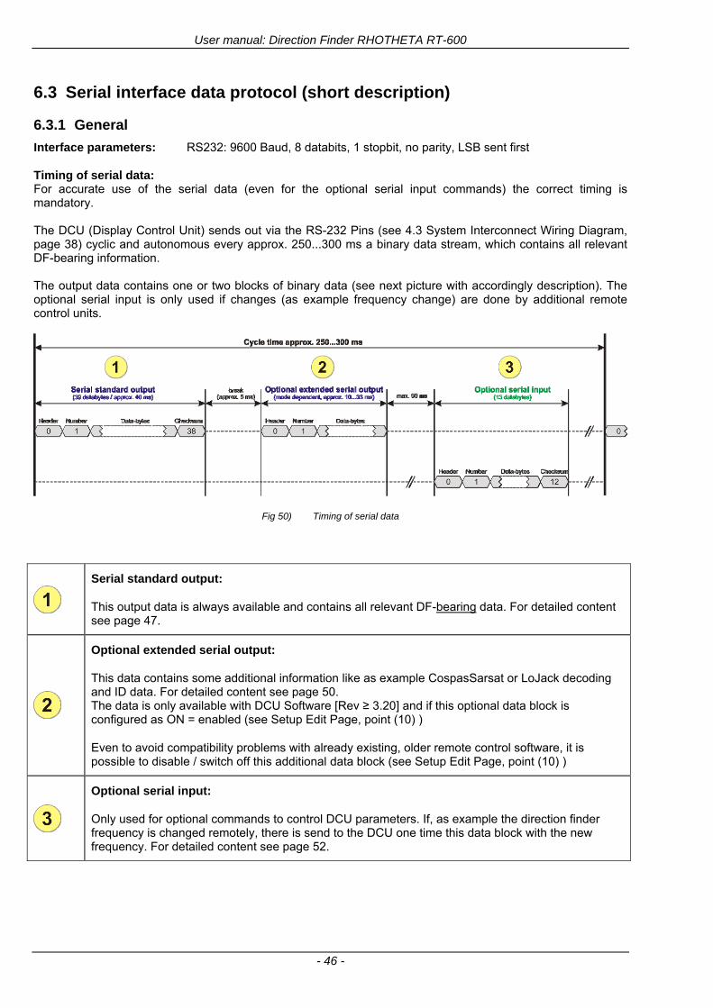
User manual Direction Finder RHOTHETA RT-600
- 46 -
63 Serial interface data protocol (short description)
631 General
Interface parameters RS232 9600 Baud 8 databits 1 stopbit no parity LSB sent first Timing of serial data For accurate use of the serial data (even for the optional serial input commands) the correct timing is mandatory The DCU (Display Control Unit) sends out via the RS-232 Pins (see 43 System Interconnect Wiring Diagram page 38) cyclic and autonomous every approx 250300 ms a binary data stream which contains all relevant DF-bearing information The output data contains one or two blocks of binary data (see next picture with accordingly description) The optional serial input is only used if changes (as example frequency change) are done by additional remote control units
Fig 50) Timing of serial data
Serial standard output
This output data is always available and contains all relevant DF-bearing data For detailed content see page 47
Optional extended serial output
This data contains some additional information like as example CospasSarsat or LoJack decoding and ID data For detailed content see page 50 The data is only available with DCU Software [Rev ge 320] and if this optional data block is configured as ON = enabled (see Setup Edit Page point (10) )
Even to avoid compatibility problems with already existing older remote control software it is possible to disable switch off this additional data block (see Setup Edit Page point (10) )
Optional serial input
Only used for optional commands to control DCU parameters If as example the direction finder frequency is changed remotely there is send to the DCU one time this data block with the new frequency For detailed content see page 52
User manual Direction Finder RHOTHETA RT-600
- 47 -
632 Serial standard output (protocol description)
Specification serial standard output
The binary data stream with a length of 39 bytes starts with a header byte (value = hex 0xA0 as ID for DF Mode) The next bytes contain different values for status bearing information and also service The last byte is used for data stream checksum control Remark This is a binary data protocol So every byte value from 0dec hellip 255dec (0x00 hellip 0xFF) is possible Because of this it is not allowed to realize a start byte detection by the content (0xA0) The idle line detection is recommended for detection the end of message Register of databytes (for details see next page)
byte no
[0] Header = 0xA0 Id for DF Mode
[1] Number = 39 = bytes in the complete message (including header and checksumbyte)
[2] Status (1) HSB [x|x|x|x|x|x|x|x] LSB | | | | | | | --gt (0) Receiving | | | | | | ----gt (1) Squelch controlled by AU (X) | | | | | ------gt (2) Permission RL Calibration | | | | --------gt (3) Line Night | | | ----------gt (4) Line NVG | | ------------gt (5) Dimming External | --------------gt (6) Autosquelch Active ----------------gt (7) 0=Standard Version 1=LE Version
[3] Status (2) HSB [x|x|x|x|x|x|x|x] LSB | ----------------gt (7) 0=Standard 1=extended serial dataprotocol = ONactive
[45] Error (Bits[120])
[6] Actual DCU Page
[7] Volume [0hellip100]
[811] Frequency [Hz]
[12] Active Band
[13] Actual Squelchlevel [0hellip60]
[14] Audio-Line amp_NF_Test Output
[15] (Not used)
[1617] Voltage_DCU ([0hellip335]=[0 hellip 335]V
[1819] Voltage_AU ([0hellip255]=[0 hellip 255]V
[20] Temperature_AU [-68hellip+127]degC
[21] Frequency Offset [-99hellip+99]
[2225] ServiceTest values (mode dependent test values for service only)
26 (Not used reserved)
[27] Level [0hellip100]
[2829] Bearing Averaged [0hellip359]deg relative
[3031] Bearing Live_Min [0hellip359]deg relative
[3233] Bearing Live_Max [0hellip359]deg relative
[34] Test Value PS-RAM Right Rotation[0hellip178] (for service only)
[35] Test Value PS-RAM Left Rotation [0hellip178] (for service only)
[3637] (Not used reserved)
[38] Checksum is the 2rsquos complement of the modulo-256 sum of all bytes without checksum-byte [0n-1]
User manual Direction Finder RHOTHETA RT-600
- 48 -
Detailed Description of important values for practical use
Status byte [2] Receiving Bit 0 of this value (LSB) indicates signal receiving Bit 0 = 0 then no signal is received and so on no bearing is available Bit 0 = 1 then bearing is possible Bit 1 if(1) then Squelch is controlled by AU (active at modes CospasSarsat Decode CospasSarsat Scanning LoJack with Filter=ID only)
Error bytes [4hellip5] 16 bit value each set bit corresponds to the error no (Refer to the chapter Error messages) Example - 0x0000 No error - 0x0800 Bit No 11 Set ( = No AU Error)
Actual DCU Page byte [6] indicates actual operating mode of DCU 0 = Standard bearing page 1 = Frequency memory page 2 = CospasSarsat decoding page 3 = LoJack decoding page (ID edit)
Frequency bytes [8hellip11] 32 bit value actual adjusted frequency [Hz] Example - 0x073DF160 1215000000 121500 MHz
Active Band Standard Version [A] 0=VHF Airband 1=VHF Marineband sea 2=VHF Marineband coast 3=UHV Airband 4=CospasSarsat LE Version [L] 0=VHF Airband 1=LoJack 2=Lifesaver 3=ETS 4=CospasSarsat
Actual Squelchlevel byte [13] Range [0hellip60] without signal the actual squelchlevel should always be adjusted a little bit over the noise level (Refer to the chapter Squelch operation)
Level byte [27] Range [099] actual receiving level (without signal this value is equal to the noise level) If a signal is received then this value corresponds to the signal strength of this signal
Relative Bearing averaged byte [2829] 16 bit value Range [0hellip359 0xFFFF] if the value = 0xFFFF then no valid bearing is available otherwise this value contains the actual averaged bearing information in Deg [0deg359deg] Example - 0X0114 276deg bearing (= left side oriented to heading)
Bearing Live MinMax byte[3031] amp [3233] - 16 bit values Range [0hellip359 0xFFFF] Only for signal quality or additional information ndash NOT recommended for bearing indication The relative live bearing field contains the maxmin bearing in degrees without averaging The relative live bearing reacts faster than the normal relative bearing but it has not the precision of the averaged bearing The MinMax Bearing Values are calculated within a time period of approx 250 ms If they are very close together (for example ldquo124rdquo and ldquo128rdquo degrees) then the signal quality is quite good A wide span of the minmax values (for example ldquo97rdquo and ldquo162rdquo) shows very noisy but nevertheless bearable signal quality
User manual Direction Finder RHOTHETA RT-600
- 49 -
633 DCU Info output (protocol description)
Specification DCU Info output
Remark This protocol is only available while the SetupEdit page is activated at the DCU
byte no
[0] Header = 0xAF Id for DCU Info Mode
[1] Number = 39 = bytes in the complete message (including header and checksumbyte)
[2]
(see standard output) [3]
[45]
[621] Info String of 15 byteschars the string contains Information about Unit Variant Software Version and Serial No
Example Byte [318] =
|--AU ID---||Var-||---Software Version---| |-------------- Serial No---------------| [0x44][0x55][0x41][0x33][0x2E][0x33][0x30][0x3A][0x20][0x20][0x30][0x31][0x32][0x33][0x34][0x00] rsquoDrsquo rsquoUrsquo rsquoArsquo rsquo3rsquo rsquorsquo rsquo3rsquo rsquo0rsquo rsquorsquo rsquo rsquo rsquo rsquo rsquo0rsquo rsquo1rsquo rsquo2rsquo rsquo3rsquo rsquo4rsquo rsquoENDrsquo | | | | __________________ | | ________________________ | n n n | | n n n n n | (Software Version) | | (Serial No) | gt rsquoArsquo = Standard Variant gt rsquoLrsquo = Law Enforcement Variant
User manual Direction Finder RHOTHETA RT-600
- 50 -
634 Optional extended serial output (protocol description)
The data content depends on the actual mode of the direction finder To get special data the direction finder has first to be switched to the equivalent mode
COSPAS-SARSAT Decoding data
This data is only available and valid if Display Control Unit with actual software Rev ge 320 (see Power-On procedure page 10) Configuration of Extended serial = ON (see Setup Edit Page point (10) ) Direction Finder COSPAS-SARSAT decoding mode is activated by selecting the corresponding page
(see COSPAS-SARSAT Decode Window page 20 and page 21) and so on Header (byte 0 of data) = 0x91
A valid COSPAS-SARSAT decoding data protocol is always marked by the first data byte (header = 0x91) Always after receiving and decoding of a valid COSPAS-SARSAT pulse the complete data protocol with 33 bytes is send out one time
Byte No
[0] Header = 0x91 (Identification for CPSarsat decoding mode)
[1] Number of bytes - 7 if no decoded pulse is available - 33 if new pulse was received and is available
[2] Error
[3] Bit[0] - 0 =gt No new 406 MSG (decoded data) available - 1 =gt New valid 406 MSG available (Sync amp Frame Ok) Check Error Status for Bit-Errors
Bit[61] AutoSquelch Level valid range [060] ( decimal)
Bit[7] = 1 Squelch controlled by AU
[4] Signallevel of received signal valid range [099] ( decimal)
[5] Voltage of Antenna Unit Power Supply input valid range [80255] (decimal = 80 255 V DC)
[6] Temperature inside Antenna Unit valid range [-50+100] (degC signed byte value)
The following databytes are only available if a correct CPSarsat puls gets received and decoded with correct checksum
[724] 18 x Databytes complete orginal CPSarsat 406 decoded message (144 bit)
Databyte Nr [ Byte 7 ] [ Byte 8 ] [Byte9 Byte24] 406 MSG Bit Nr [1 2 3 4 5 6 7 8] [9 10 11 12 13 14 15 16] [17 144]
[25] SN-Flag valid values 0x53=rsquoSrsquo 0x4E=rsquoNrsquo 0x2D=rsquo-rsquo if no GPS data available
GPS-Position Latitude
[26] Deg valid values [090] (decimal Deg) 0xFF if no GPS data available
[27] Min valid values [059] (decimal Deg) 0xFF if no GPS data available
[28] Sec valid values [059] (decimal Deg) 0xFF if no GPS data available
[29] WE-Flag valid values 0x57=rsquoWrsquo 0x45=rsquoErsquo 0x2D=rsquo-rsquo if no GPS data available
GPS-Position Longitude
[30] Deg valid values [0180] (decimal Deg) 0xFF if no GPS data available
[31] Min valid values [059] (decimal Deg) 0xFF if no GPS data available
[32] Sec valid values [059] (decimal Deg) 0xFF if no GPS data available
User manual Direction Finder RHOTHETA RT-600
- 51 -
LoJack ID data
This data is only available and valid if Display Control Unit with actual software Rev ge 320 (see Power-On procedure page 10) Direction Finder of variant [L] Law Enforcement Configuration of Extended serial = ON (see Setup Edit Page point (10) ) Direction Finder is working with active LoJack gtID Filterlt Header (byte 0 of data) = 0x93 or 0x94
Valid LoJack ID decoding data is always marked by the first data byte (header = 0x93 or 0x94)
Byte No
[0] Header = 0x93 LoJack ID editing sub-page is selected Filter = VLU all valid and received LoJack pulses are indicated = 0x94 Lojack Decode amp DF Mode with active Filter = ID
[1] Number of bytes in the complete data stream - decimal 26 = default value
[2] Nonrelevant
[3] Bit[0] Receiving OnOff - 0 =gt No Receiving no bearing - 1 =gt new LoJack pulse received
[412] Nonrelevant
[1317] Lojack ID
Replay Code 5 x ASCII Chars ldquoNo BIOZrdquo set
Example ASCII = ldquo000R1rdquo
18 Receiver Level Out Max [099]
19
LoJack Decoder Status [07] - 0 Off - 1 Wait for Preamble - 2 Preamble Ok - 3 FlagPattern Ok - 4 Data BitError gt 1 - 5 Data Ok (No VLU) - 6 VLU Ok - 7 ID Ok (Filter=IDONLY)
[2025] Nonrelevant
Remark Only if byte no [3] bit [0] gets ldquo1rdquo (Receiving On) then an active LoJack pulse is received and so on the corresponding LoJack ID valid otherwise the LoJack ID only shows the actual adjusted LoJack Filter ID of the direction finder
User manual Direction Finder RHOTHETA RT-600
- 52 -
635 Optional serial input (protocol description)
Specification serial input (optional)
The serial input is normally used for service and maintenance only Nevertheless it is possible via this interface to remote control the actual frequency and the squelchlevel of the DF system If a valid data stream is send to the DF then the actual frequency selection at the DCU is switched to Block2 AUX0 At this memory channel the new frequency is stored and used automatically (Refer to the chapter Frequency Selection Page) If the frequency is changed (by one valid data stream) no more serial input is necessary The actual frequency can be changed again at any time by manual operation at the DCU The timing of serial input (if used) is strictly fixed The optional serial input has to take place directly after a complete serial output (max 50 ms delay time) If a new changed frequency is commanded to the DCU via this serial input interface it can take up to 1 sec of time until this new frequency is ready for operationbearing It is strictly not recommended to use the frequency remote control for any scan mode The frequency control has to be used for static frequency change only Register of databytes
byte no
[0] Header 0xC0
[1] Number of bytes in the complete message (including header and checksumbyte)
[23] (not used for normal operation any byte values allowed)
[4] Volume [0100]
[58] Frequency [Hz] (frequency is rounded to the according grid automatically)
Valid Range for Standard Version Valid Range for LE Version
118000000 hellip 123000000 [Hz] 8333 kHz 118000000 hellip 123000000 [Hz] 8333 kHz
156050000 hellip 162025000 [Hz] 5000 kHz 164000000 hellip 174000000 [Hz] 8333 kHz
201000000 hellip 215995000 [Hz] 5000 kHz
240000000 hellip 246000000 [Hz] 8333 kHz 216000000 hellip 218995000 [Hz] 12500 kHz219000000 hellip 220000000 [Hz] 10000 kHz
400000000 hellip 410000000 [Hz] 8333 kHz 400000000 hellip 410000000 [Hz] 8333 kHz
[9] Squelchlevel Manual = [0hellip60] Autosql= [ -1] Warning use only for pulsed signals (as example CpSarsat LoJack)
[10] (not used for normal operation any byte values allowed)
[11] Internal Dimming [0100]
[12] Checksum is the 2rsquos complement of the modulo-256 sum of all bytes without checksum-byte [0n-1]
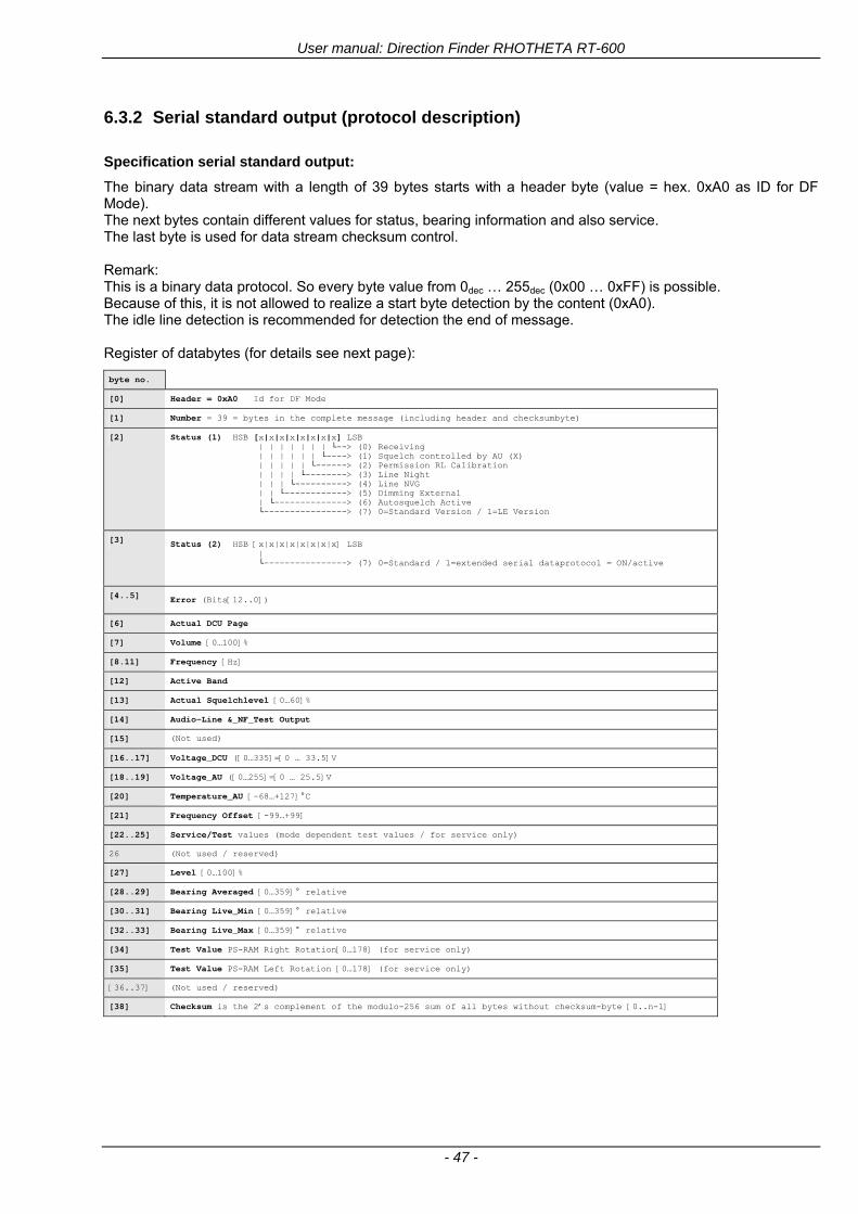
User manual Direction Finder RHOTHETA RT-600
- 47 -
632 Serial standard output (protocol description)
Specification serial standard output
The binary data stream with a length of 39 bytes starts with a header byte (value = hex 0xA0 as ID for DF Mode) The next bytes contain different values for status bearing information and also service The last byte is used for data stream checksum control Remark This is a binary data protocol So every byte value from 0dec hellip 255dec (0x00 hellip 0xFF) is possible Because of this it is not allowed to realize a start byte detection by the content (0xA0) The idle line detection is recommended for detection the end of message Register of databytes (for details see next page)
byte no
[0] Header = 0xA0 Id for DF Mode
[1] Number = 39 = bytes in the complete message (including header and checksumbyte)
[2] Status (1) HSB [x|x|x|x|x|x|x|x] LSB | | | | | | | --gt (0) Receiving | | | | | | ----gt (1) Squelch controlled by AU (X) | | | | | ------gt (2) Permission RL Calibration | | | | --------gt (3) Line Night | | | ----------gt (4) Line NVG | | ------------gt (5) Dimming External | --------------gt (6) Autosquelch Active ----------------gt (7) 0=Standard Version 1=LE Version
[3] Status (2) HSB [x|x|x|x|x|x|x|x] LSB | ----------------gt (7) 0=Standard 1=extended serial dataprotocol = ONactive
[45] Error (Bits[120])
[6] Actual DCU Page
[7] Volume [0hellip100]
[811] Frequency [Hz]
[12] Active Band
[13] Actual Squelchlevel [0hellip60]
[14] Audio-Line amp_NF_Test Output
[15] (Not used)
[1617] Voltage_DCU ([0hellip335]=[0 hellip 335]V
[1819] Voltage_AU ([0hellip255]=[0 hellip 255]V
[20] Temperature_AU [-68hellip+127]degC
[21] Frequency Offset [-99hellip+99]
[2225] ServiceTest values (mode dependent test values for service only)
26 (Not used reserved)
[27] Level [0hellip100]
[2829] Bearing Averaged [0hellip359]deg relative
[3031] Bearing Live_Min [0hellip359]deg relative
[3233] Bearing Live_Max [0hellip359]deg relative
[34] Test Value PS-RAM Right Rotation[0hellip178] (for service only)
[35] Test Value PS-RAM Left Rotation [0hellip178] (for service only)
[3637] (Not used reserved)
[38] Checksum is the 2rsquos complement of the modulo-256 sum of all bytes without checksum-byte [0n-1]
User manual Direction Finder RHOTHETA RT-600
- 48 -
Detailed Description of important values for practical use
Status byte [2] Receiving Bit 0 of this value (LSB) indicates signal receiving Bit 0 = 0 then no signal is received and so on no bearing is available Bit 0 = 1 then bearing is possible Bit 1 if(1) then Squelch is controlled by AU (active at modes CospasSarsat Decode CospasSarsat Scanning LoJack with Filter=ID only)
Error bytes [4hellip5] 16 bit value each set bit corresponds to the error no (Refer to the chapter Error messages) Example - 0x0000 No error - 0x0800 Bit No 11 Set ( = No AU Error)
Actual DCU Page byte [6] indicates actual operating mode of DCU 0 = Standard bearing page 1 = Frequency memory page 2 = CospasSarsat decoding page 3 = LoJack decoding page (ID edit)
Frequency bytes [8hellip11] 32 bit value actual adjusted frequency [Hz] Example - 0x073DF160 1215000000 121500 MHz
Active Band Standard Version [A] 0=VHF Airband 1=VHF Marineband sea 2=VHF Marineband coast 3=UHV Airband 4=CospasSarsat LE Version [L] 0=VHF Airband 1=LoJack 2=Lifesaver 3=ETS 4=CospasSarsat
Actual Squelchlevel byte [13] Range [0hellip60] without signal the actual squelchlevel should always be adjusted a little bit over the noise level (Refer to the chapter Squelch operation)
Level byte [27] Range [099] actual receiving level (without signal this value is equal to the noise level) If a signal is received then this value corresponds to the signal strength of this signal
Relative Bearing averaged byte [2829] 16 bit value Range [0hellip359 0xFFFF] if the value = 0xFFFF then no valid bearing is available otherwise this value contains the actual averaged bearing information in Deg [0deg359deg] Example - 0X0114 276deg bearing (= left side oriented to heading)
Bearing Live MinMax byte[3031] amp [3233] - 16 bit values Range [0hellip359 0xFFFF] Only for signal quality or additional information ndash NOT recommended for bearing indication The relative live bearing field contains the maxmin bearing in degrees without averaging The relative live bearing reacts faster than the normal relative bearing but it has not the precision of the averaged bearing The MinMax Bearing Values are calculated within a time period of approx 250 ms If they are very close together (for example ldquo124rdquo and ldquo128rdquo degrees) then the signal quality is quite good A wide span of the minmax values (for example ldquo97rdquo and ldquo162rdquo) shows very noisy but nevertheless bearable signal quality
User manual Direction Finder RHOTHETA RT-600
- 49 -
633 DCU Info output (protocol description)
Specification DCU Info output
Remark This protocol is only available while the SetupEdit page is activated at the DCU
byte no
[0] Header = 0xAF Id for DCU Info Mode
[1] Number = 39 = bytes in the complete message (including header and checksumbyte)
[2]
(see standard output) [3]
[45]
[621] Info String of 15 byteschars the string contains Information about Unit Variant Software Version and Serial No
Example Byte [318] =
|--AU ID---||Var-||---Software Version---| |-------------- Serial No---------------| [0x44][0x55][0x41][0x33][0x2E][0x33][0x30][0x3A][0x20][0x20][0x30][0x31][0x32][0x33][0x34][0x00] rsquoDrsquo rsquoUrsquo rsquoArsquo rsquo3rsquo rsquorsquo rsquo3rsquo rsquo0rsquo rsquorsquo rsquo rsquo rsquo rsquo rsquo0rsquo rsquo1rsquo rsquo2rsquo rsquo3rsquo rsquo4rsquo rsquoENDrsquo | | | | __________________ | | ________________________ | n n n | | n n n n n | (Software Version) | | (Serial No) | gt rsquoArsquo = Standard Variant gt rsquoLrsquo = Law Enforcement Variant
User manual Direction Finder RHOTHETA RT-600
- 50 -
634 Optional extended serial output (protocol description)
The data content depends on the actual mode of the direction finder To get special data the direction finder has first to be switched to the equivalent mode
COSPAS-SARSAT Decoding data
This data is only available and valid if Display Control Unit with actual software Rev ge 320 (see Power-On procedure page 10) Configuration of Extended serial = ON (see Setup Edit Page point (10) ) Direction Finder COSPAS-SARSAT decoding mode is activated by selecting the corresponding page
(see COSPAS-SARSAT Decode Window page 20 and page 21) and so on Header (byte 0 of data) = 0x91
A valid COSPAS-SARSAT decoding data protocol is always marked by the first data byte (header = 0x91) Always after receiving and decoding of a valid COSPAS-SARSAT pulse the complete data protocol with 33 bytes is send out one time
Byte No
[0] Header = 0x91 (Identification for CPSarsat decoding mode)
[1] Number of bytes - 7 if no decoded pulse is available - 33 if new pulse was received and is available
[2] Error
[3] Bit[0] - 0 =gt No new 406 MSG (decoded data) available - 1 =gt New valid 406 MSG available (Sync amp Frame Ok) Check Error Status for Bit-Errors
Bit[61] AutoSquelch Level valid range [060] ( decimal)
Bit[7] = 1 Squelch controlled by AU
[4] Signallevel of received signal valid range [099] ( decimal)
[5] Voltage of Antenna Unit Power Supply input valid range [80255] (decimal = 80 255 V DC)
[6] Temperature inside Antenna Unit valid range [-50+100] (degC signed byte value)
The following databytes are only available if a correct CPSarsat puls gets received and decoded with correct checksum
[724] 18 x Databytes complete orginal CPSarsat 406 decoded message (144 bit)
Databyte Nr [ Byte 7 ] [ Byte 8 ] [Byte9 Byte24] 406 MSG Bit Nr [1 2 3 4 5 6 7 8] [9 10 11 12 13 14 15 16] [17 144]
[25] SN-Flag valid values 0x53=rsquoSrsquo 0x4E=rsquoNrsquo 0x2D=rsquo-rsquo if no GPS data available
GPS-Position Latitude
[26] Deg valid values [090] (decimal Deg) 0xFF if no GPS data available
[27] Min valid values [059] (decimal Deg) 0xFF if no GPS data available
[28] Sec valid values [059] (decimal Deg) 0xFF if no GPS data available
[29] WE-Flag valid values 0x57=rsquoWrsquo 0x45=rsquoErsquo 0x2D=rsquo-rsquo if no GPS data available
GPS-Position Longitude
[30] Deg valid values [0180] (decimal Deg) 0xFF if no GPS data available
[31] Min valid values [059] (decimal Deg) 0xFF if no GPS data available
[32] Sec valid values [059] (decimal Deg) 0xFF if no GPS data available
User manual Direction Finder RHOTHETA RT-600
- 51 -
LoJack ID data
This data is only available and valid if Display Control Unit with actual software Rev ge 320 (see Power-On procedure page 10) Direction Finder of variant [L] Law Enforcement Configuration of Extended serial = ON (see Setup Edit Page point (10) ) Direction Finder is working with active LoJack gtID Filterlt Header (byte 0 of data) = 0x93 or 0x94
Valid LoJack ID decoding data is always marked by the first data byte (header = 0x93 or 0x94)
Byte No
[0] Header = 0x93 LoJack ID editing sub-page is selected Filter = VLU all valid and received LoJack pulses are indicated = 0x94 Lojack Decode amp DF Mode with active Filter = ID
[1] Number of bytes in the complete data stream - decimal 26 = default value
[2] Nonrelevant
[3] Bit[0] Receiving OnOff - 0 =gt No Receiving no bearing - 1 =gt new LoJack pulse received
[412] Nonrelevant
[1317] Lojack ID
Replay Code 5 x ASCII Chars ldquoNo BIOZrdquo set
Example ASCII = ldquo000R1rdquo
18 Receiver Level Out Max [099]
19
LoJack Decoder Status [07] - 0 Off - 1 Wait for Preamble - 2 Preamble Ok - 3 FlagPattern Ok - 4 Data BitError gt 1 - 5 Data Ok (No VLU) - 6 VLU Ok - 7 ID Ok (Filter=IDONLY)
[2025] Nonrelevant
Remark Only if byte no [3] bit [0] gets ldquo1rdquo (Receiving On) then an active LoJack pulse is received and so on the corresponding LoJack ID valid otherwise the LoJack ID only shows the actual adjusted LoJack Filter ID of the direction finder
User manual Direction Finder RHOTHETA RT-600
- 52 -
635 Optional serial input (protocol description)
Specification serial input (optional)
The serial input is normally used for service and maintenance only Nevertheless it is possible via this interface to remote control the actual frequency and the squelchlevel of the DF system If a valid data stream is send to the DF then the actual frequency selection at the DCU is switched to Block2 AUX0 At this memory channel the new frequency is stored and used automatically (Refer to the chapter Frequency Selection Page) If the frequency is changed (by one valid data stream) no more serial input is necessary The actual frequency can be changed again at any time by manual operation at the DCU The timing of serial input (if used) is strictly fixed The optional serial input has to take place directly after a complete serial output (max 50 ms delay time) If a new changed frequency is commanded to the DCU via this serial input interface it can take up to 1 sec of time until this new frequency is ready for operationbearing It is strictly not recommended to use the frequency remote control for any scan mode The frequency control has to be used for static frequency change only Register of databytes
byte no
[0] Header 0xC0
[1] Number of bytes in the complete message (including header and checksumbyte)
[23] (not used for normal operation any byte values allowed)
[4] Volume [0100]
[58] Frequency [Hz] (frequency is rounded to the according grid automatically)
Valid Range for Standard Version Valid Range for LE Version
118000000 hellip 123000000 [Hz] 8333 kHz 118000000 hellip 123000000 [Hz] 8333 kHz
156050000 hellip 162025000 [Hz] 5000 kHz 164000000 hellip 174000000 [Hz] 8333 kHz
201000000 hellip 215995000 [Hz] 5000 kHz
240000000 hellip 246000000 [Hz] 8333 kHz 216000000 hellip 218995000 [Hz] 12500 kHz219000000 hellip 220000000 [Hz] 10000 kHz
400000000 hellip 410000000 [Hz] 8333 kHz 400000000 hellip 410000000 [Hz] 8333 kHz
[9] Squelchlevel Manual = [0hellip60] Autosql= [ -1] Warning use only for pulsed signals (as example CpSarsat LoJack)
[10] (not used for normal operation any byte values allowed)
[11] Internal Dimming [0100]
[12] Checksum is the 2rsquos complement of the modulo-256 sum of all bytes without checksum-byte [0n-1]
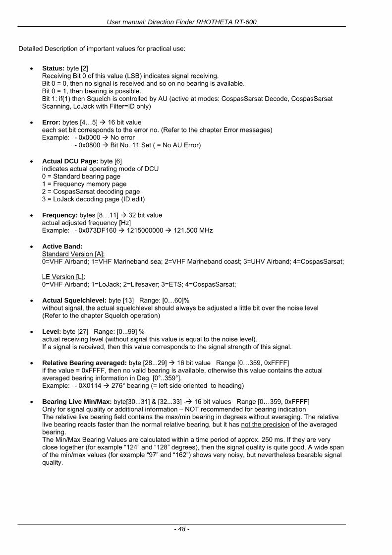
User manual Direction Finder RHOTHETA RT-600
- 48 -
Detailed Description of important values for practical use
Status byte [2] Receiving Bit 0 of this value (LSB) indicates signal receiving Bit 0 = 0 then no signal is received and so on no bearing is available Bit 0 = 1 then bearing is possible Bit 1 if(1) then Squelch is controlled by AU (active at modes CospasSarsat Decode CospasSarsat Scanning LoJack with Filter=ID only)
Error bytes [4hellip5] 16 bit value each set bit corresponds to the error no (Refer to the chapter Error messages) Example - 0x0000 No error - 0x0800 Bit No 11 Set ( = No AU Error)
Actual DCU Page byte [6] indicates actual operating mode of DCU 0 = Standard bearing page 1 = Frequency memory page 2 = CospasSarsat decoding page 3 = LoJack decoding page (ID edit)
Frequency bytes [8hellip11] 32 bit value actual adjusted frequency [Hz] Example - 0x073DF160 1215000000 121500 MHz
Active Band Standard Version [A] 0=VHF Airband 1=VHF Marineband sea 2=VHF Marineband coast 3=UHV Airband 4=CospasSarsat LE Version [L] 0=VHF Airband 1=LoJack 2=Lifesaver 3=ETS 4=CospasSarsat
Actual Squelchlevel byte [13] Range [0hellip60] without signal the actual squelchlevel should always be adjusted a little bit over the noise level (Refer to the chapter Squelch operation)
Level byte [27] Range [099] actual receiving level (without signal this value is equal to the noise level) If a signal is received then this value corresponds to the signal strength of this signal
Relative Bearing averaged byte [2829] 16 bit value Range [0hellip359 0xFFFF] if the value = 0xFFFF then no valid bearing is available otherwise this value contains the actual averaged bearing information in Deg [0deg359deg] Example - 0X0114 276deg bearing (= left side oriented to heading)
Bearing Live MinMax byte[3031] amp [3233] - 16 bit values Range [0hellip359 0xFFFF] Only for signal quality or additional information ndash NOT recommended for bearing indication The relative live bearing field contains the maxmin bearing in degrees without averaging The relative live bearing reacts faster than the normal relative bearing but it has not the precision of the averaged bearing The MinMax Bearing Values are calculated within a time period of approx 250 ms If they are very close together (for example ldquo124rdquo and ldquo128rdquo degrees) then the signal quality is quite good A wide span of the minmax values (for example ldquo97rdquo and ldquo162rdquo) shows very noisy but nevertheless bearable signal quality
User manual Direction Finder RHOTHETA RT-600
- 49 -
633 DCU Info output (protocol description)
Specification DCU Info output
Remark This protocol is only available while the SetupEdit page is activated at the DCU
byte no
[0] Header = 0xAF Id for DCU Info Mode
[1] Number = 39 = bytes in the complete message (including header and checksumbyte)
[2]
(see standard output) [3]
[45]
[621] Info String of 15 byteschars the string contains Information about Unit Variant Software Version and Serial No
Example Byte [318] =
|--AU ID---||Var-||---Software Version---| |-------------- Serial No---------------| [0x44][0x55][0x41][0x33][0x2E][0x33][0x30][0x3A][0x20][0x20][0x30][0x31][0x32][0x33][0x34][0x00] rsquoDrsquo rsquoUrsquo rsquoArsquo rsquo3rsquo rsquorsquo rsquo3rsquo rsquo0rsquo rsquorsquo rsquo rsquo rsquo rsquo rsquo0rsquo rsquo1rsquo rsquo2rsquo rsquo3rsquo rsquo4rsquo rsquoENDrsquo | | | | __________________ | | ________________________ | n n n | | n n n n n | (Software Version) | | (Serial No) | gt rsquoArsquo = Standard Variant gt rsquoLrsquo = Law Enforcement Variant
User manual Direction Finder RHOTHETA RT-600
- 50 -
634 Optional extended serial output (protocol description)
The data content depends on the actual mode of the direction finder To get special data the direction finder has first to be switched to the equivalent mode
COSPAS-SARSAT Decoding data
This data is only available and valid if Display Control Unit with actual software Rev ge 320 (see Power-On procedure page 10) Configuration of Extended serial = ON (see Setup Edit Page point (10) ) Direction Finder COSPAS-SARSAT decoding mode is activated by selecting the corresponding page
(see COSPAS-SARSAT Decode Window page 20 and page 21) and so on Header (byte 0 of data) = 0x91
A valid COSPAS-SARSAT decoding data protocol is always marked by the first data byte (header = 0x91) Always after receiving and decoding of a valid COSPAS-SARSAT pulse the complete data protocol with 33 bytes is send out one time
Byte No
[0] Header = 0x91 (Identification for CPSarsat decoding mode)
[1] Number of bytes - 7 if no decoded pulse is available - 33 if new pulse was received and is available
[2] Error
[3] Bit[0] - 0 =gt No new 406 MSG (decoded data) available - 1 =gt New valid 406 MSG available (Sync amp Frame Ok) Check Error Status for Bit-Errors
Bit[61] AutoSquelch Level valid range [060] ( decimal)
Bit[7] = 1 Squelch controlled by AU
[4] Signallevel of received signal valid range [099] ( decimal)
[5] Voltage of Antenna Unit Power Supply input valid range [80255] (decimal = 80 255 V DC)
[6] Temperature inside Antenna Unit valid range [-50+100] (degC signed byte value)
The following databytes are only available if a correct CPSarsat puls gets received and decoded with correct checksum
[724] 18 x Databytes complete orginal CPSarsat 406 decoded message (144 bit)
Databyte Nr [ Byte 7 ] [ Byte 8 ] [Byte9 Byte24] 406 MSG Bit Nr [1 2 3 4 5 6 7 8] [9 10 11 12 13 14 15 16] [17 144]
[25] SN-Flag valid values 0x53=rsquoSrsquo 0x4E=rsquoNrsquo 0x2D=rsquo-rsquo if no GPS data available
GPS-Position Latitude
[26] Deg valid values [090] (decimal Deg) 0xFF if no GPS data available
[27] Min valid values [059] (decimal Deg) 0xFF if no GPS data available
[28] Sec valid values [059] (decimal Deg) 0xFF if no GPS data available
[29] WE-Flag valid values 0x57=rsquoWrsquo 0x45=rsquoErsquo 0x2D=rsquo-rsquo if no GPS data available
GPS-Position Longitude
[30] Deg valid values [0180] (decimal Deg) 0xFF if no GPS data available
[31] Min valid values [059] (decimal Deg) 0xFF if no GPS data available
[32] Sec valid values [059] (decimal Deg) 0xFF if no GPS data available
User manual Direction Finder RHOTHETA RT-600
- 51 -
LoJack ID data
This data is only available and valid if Display Control Unit with actual software Rev ge 320 (see Power-On procedure page 10) Direction Finder of variant [L] Law Enforcement Configuration of Extended serial = ON (see Setup Edit Page point (10) ) Direction Finder is working with active LoJack gtID Filterlt Header (byte 0 of data) = 0x93 or 0x94
Valid LoJack ID decoding data is always marked by the first data byte (header = 0x93 or 0x94)
Byte No
[0] Header = 0x93 LoJack ID editing sub-page is selected Filter = VLU all valid and received LoJack pulses are indicated = 0x94 Lojack Decode amp DF Mode with active Filter = ID
[1] Number of bytes in the complete data stream - decimal 26 = default value
[2] Nonrelevant
[3] Bit[0] Receiving OnOff - 0 =gt No Receiving no bearing - 1 =gt new LoJack pulse received
[412] Nonrelevant
[1317] Lojack ID
Replay Code 5 x ASCII Chars ldquoNo BIOZrdquo set
Example ASCII = ldquo000R1rdquo
18 Receiver Level Out Max [099]
19
LoJack Decoder Status [07] - 0 Off - 1 Wait for Preamble - 2 Preamble Ok - 3 FlagPattern Ok - 4 Data BitError gt 1 - 5 Data Ok (No VLU) - 6 VLU Ok - 7 ID Ok (Filter=IDONLY)
[2025] Nonrelevant
Remark Only if byte no [3] bit [0] gets ldquo1rdquo (Receiving On) then an active LoJack pulse is received and so on the corresponding LoJack ID valid otherwise the LoJack ID only shows the actual adjusted LoJack Filter ID of the direction finder
User manual Direction Finder RHOTHETA RT-600
- 52 -
635 Optional serial input (protocol description)
Specification serial input (optional)
The serial input is normally used for service and maintenance only Nevertheless it is possible via this interface to remote control the actual frequency and the squelchlevel of the DF system If a valid data stream is send to the DF then the actual frequency selection at the DCU is switched to Block2 AUX0 At this memory channel the new frequency is stored and used automatically (Refer to the chapter Frequency Selection Page) If the frequency is changed (by one valid data stream) no more serial input is necessary The actual frequency can be changed again at any time by manual operation at the DCU The timing of serial input (if used) is strictly fixed The optional serial input has to take place directly after a complete serial output (max 50 ms delay time) If a new changed frequency is commanded to the DCU via this serial input interface it can take up to 1 sec of time until this new frequency is ready for operationbearing It is strictly not recommended to use the frequency remote control for any scan mode The frequency control has to be used for static frequency change only Register of databytes
byte no
[0] Header 0xC0
[1] Number of bytes in the complete message (including header and checksumbyte)
[23] (not used for normal operation any byte values allowed)
[4] Volume [0100]
[58] Frequency [Hz] (frequency is rounded to the according grid automatically)
Valid Range for Standard Version Valid Range for LE Version
118000000 hellip 123000000 [Hz] 8333 kHz 118000000 hellip 123000000 [Hz] 8333 kHz
156050000 hellip 162025000 [Hz] 5000 kHz 164000000 hellip 174000000 [Hz] 8333 kHz
201000000 hellip 215995000 [Hz] 5000 kHz
240000000 hellip 246000000 [Hz] 8333 kHz 216000000 hellip 218995000 [Hz] 12500 kHz219000000 hellip 220000000 [Hz] 10000 kHz
400000000 hellip 410000000 [Hz] 8333 kHz 400000000 hellip 410000000 [Hz] 8333 kHz
[9] Squelchlevel Manual = [0hellip60] Autosql= [ -1] Warning use only for pulsed signals (as example CpSarsat LoJack)
[10] (not used for normal operation any byte values allowed)
[11] Internal Dimming [0100]
[12] Checksum is the 2rsquos complement of the modulo-256 sum of all bytes without checksum-byte [0n-1]
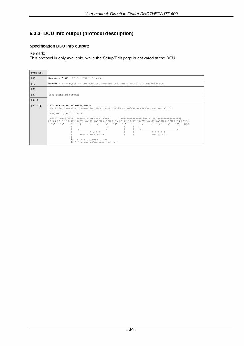
User manual Direction Finder RHOTHETA RT-600
- 49 -
633 DCU Info output (protocol description)
Specification DCU Info output
Remark This protocol is only available while the SetupEdit page is activated at the DCU
byte no
[0] Header = 0xAF Id for DCU Info Mode
[1] Number = 39 = bytes in the complete message (including header and checksumbyte)
[2]
(see standard output) [3]
[45]
[621] Info String of 15 byteschars the string contains Information about Unit Variant Software Version and Serial No
Example Byte [318] =
|--AU ID---||Var-||---Software Version---| |-------------- Serial No---------------| [0x44][0x55][0x41][0x33][0x2E][0x33][0x30][0x3A][0x20][0x20][0x30][0x31][0x32][0x33][0x34][0x00] rsquoDrsquo rsquoUrsquo rsquoArsquo rsquo3rsquo rsquorsquo rsquo3rsquo rsquo0rsquo rsquorsquo rsquo rsquo rsquo rsquo rsquo0rsquo rsquo1rsquo rsquo2rsquo rsquo3rsquo rsquo4rsquo rsquoENDrsquo | | | | __________________ | | ________________________ | n n n | | n n n n n | (Software Version) | | (Serial No) | gt rsquoArsquo = Standard Variant gt rsquoLrsquo = Law Enforcement Variant
User manual Direction Finder RHOTHETA RT-600
- 50 -
634 Optional extended serial output (protocol description)
The data content depends on the actual mode of the direction finder To get special data the direction finder has first to be switched to the equivalent mode
COSPAS-SARSAT Decoding data
This data is only available and valid if Display Control Unit with actual software Rev ge 320 (see Power-On procedure page 10) Configuration of Extended serial = ON (see Setup Edit Page point (10) ) Direction Finder COSPAS-SARSAT decoding mode is activated by selecting the corresponding page
(see COSPAS-SARSAT Decode Window page 20 and page 21) and so on Header (byte 0 of data) = 0x91
A valid COSPAS-SARSAT decoding data protocol is always marked by the first data byte (header = 0x91) Always after receiving and decoding of a valid COSPAS-SARSAT pulse the complete data protocol with 33 bytes is send out one time
Byte No
[0] Header = 0x91 (Identification for CPSarsat decoding mode)
[1] Number of bytes - 7 if no decoded pulse is available - 33 if new pulse was received and is available
[2] Error
[3] Bit[0] - 0 =gt No new 406 MSG (decoded data) available - 1 =gt New valid 406 MSG available (Sync amp Frame Ok) Check Error Status for Bit-Errors
Bit[61] AutoSquelch Level valid range [060] ( decimal)
Bit[7] = 1 Squelch controlled by AU
[4] Signallevel of received signal valid range [099] ( decimal)
[5] Voltage of Antenna Unit Power Supply input valid range [80255] (decimal = 80 255 V DC)
[6] Temperature inside Antenna Unit valid range [-50+100] (degC signed byte value)
The following databytes are only available if a correct CPSarsat puls gets received and decoded with correct checksum
[724] 18 x Databytes complete orginal CPSarsat 406 decoded message (144 bit)
Databyte Nr [ Byte 7 ] [ Byte 8 ] [Byte9 Byte24] 406 MSG Bit Nr [1 2 3 4 5 6 7 8] [9 10 11 12 13 14 15 16] [17 144]
[25] SN-Flag valid values 0x53=rsquoSrsquo 0x4E=rsquoNrsquo 0x2D=rsquo-rsquo if no GPS data available
GPS-Position Latitude
[26] Deg valid values [090] (decimal Deg) 0xFF if no GPS data available
[27] Min valid values [059] (decimal Deg) 0xFF if no GPS data available
[28] Sec valid values [059] (decimal Deg) 0xFF if no GPS data available
[29] WE-Flag valid values 0x57=rsquoWrsquo 0x45=rsquoErsquo 0x2D=rsquo-rsquo if no GPS data available
GPS-Position Longitude
[30] Deg valid values [0180] (decimal Deg) 0xFF if no GPS data available
[31] Min valid values [059] (decimal Deg) 0xFF if no GPS data available
[32] Sec valid values [059] (decimal Deg) 0xFF if no GPS data available
User manual Direction Finder RHOTHETA RT-600
- 51 -
LoJack ID data
This data is only available and valid if Display Control Unit with actual software Rev ge 320 (see Power-On procedure page 10) Direction Finder of variant [L] Law Enforcement Configuration of Extended serial = ON (see Setup Edit Page point (10) ) Direction Finder is working with active LoJack gtID Filterlt Header (byte 0 of data) = 0x93 or 0x94
Valid LoJack ID decoding data is always marked by the first data byte (header = 0x93 or 0x94)
Byte No
[0] Header = 0x93 LoJack ID editing sub-page is selected Filter = VLU all valid and received LoJack pulses are indicated = 0x94 Lojack Decode amp DF Mode with active Filter = ID
[1] Number of bytes in the complete data stream - decimal 26 = default value
[2] Nonrelevant
[3] Bit[0] Receiving OnOff - 0 =gt No Receiving no bearing - 1 =gt new LoJack pulse received
[412] Nonrelevant
[1317] Lojack ID
Replay Code 5 x ASCII Chars ldquoNo BIOZrdquo set
Example ASCII = ldquo000R1rdquo
18 Receiver Level Out Max [099]
19
LoJack Decoder Status [07] - 0 Off - 1 Wait for Preamble - 2 Preamble Ok - 3 FlagPattern Ok - 4 Data BitError gt 1 - 5 Data Ok (No VLU) - 6 VLU Ok - 7 ID Ok (Filter=IDONLY)
[2025] Nonrelevant
Remark Only if byte no [3] bit [0] gets ldquo1rdquo (Receiving On) then an active LoJack pulse is received and so on the corresponding LoJack ID valid otherwise the LoJack ID only shows the actual adjusted LoJack Filter ID of the direction finder
User manual Direction Finder RHOTHETA RT-600
- 52 -
635 Optional serial input (protocol description)
Specification serial input (optional)
The serial input is normally used for service and maintenance only Nevertheless it is possible via this interface to remote control the actual frequency and the squelchlevel of the DF system If a valid data stream is send to the DF then the actual frequency selection at the DCU is switched to Block2 AUX0 At this memory channel the new frequency is stored and used automatically (Refer to the chapter Frequency Selection Page) If the frequency is changed (by one valid data stream) no more serial input is necessary The actual frequency can be changed again at any time by manual operation at the DCU The timing of serial input (if used) is strictly fixed The optional serial input has to take place directly after a complete serial output (max 50 ms delay time) If a new changed frequency is commanded to the DCU via this serial input interface it can take up to 1 sec of time until this new frequency is ready for operationbearing It is strictly not recommended to use the frequency remote control for any scan mode The frequency control has to be used for static frequency change only Register of databytes
byte no
[0] Header 0xC0
[1] Number of bytes in the complete message (including header and checksumbyte)
[23] (not used for normal operation any byte values allowed)
[4] Volume [0100]
[58] Frequency [Hz] (frequency is rounded to the according grid automatically)
Valid Range for Standard Version Valid Range for LE Version
118000000 hellip 123000000 [Hz] 8333 kHz 118000000 hellip 123000000 [Hz] 8333 kHz
156050000 hellip 162025000 [Hz] 5000 kHz 164000000 hellip 174000000 [Hz] 8333 kHz
201000000 hellip 215995000 [Hz] 5000 kHz
240000000 hellip 246000000 [Hz] 8333 kHz 216000000 hellip 218995000 [Hz] 12500 kHz219000000 hellip 220000000 [Hz] 10000 kHz
400000000 hellip 410000000 [Hz] 8333 kHz 400000000 hellip 410000000 [Hz] 8333 kHz
[9] Squelchlevel Manual = [0hellip60] Autosql= [ -1] Warning use only for pulsed signals (as example CpSarsat LoJack)
[10] (not used for normal operation any byte values allowed)
[11] Internal Dimming [0100]
[12] Checksum is the 2rsquos complement of the modulo-256 sum of all bytes without checksum-byte [0n-1]
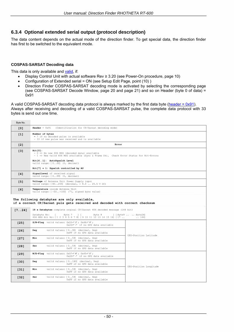
User manual Direction Finder RHOTHETA RT-600
- 50 -
634 Optional extended serial output (protocol description)
The data content depends on the actual mode of the direction finder To get special data the direction finder has first to be switched to the equivalent mode
COSPAS-SARSAT Decoding data
This data is only available and valid if Display Control Unit with actual software Rev ge 320 (see Power-On procedure page 10) Configuration of Extended serial = ON (see Setup Edit Page point (10) ) Direction Finder COSPAS-SARSAT decoding mode is activated by selecting the corresponding page
(see COSPAS-SARSAT Decode Window page 20 and page 21) and so on Header (byte 0 of data) = 0x91
A valid COSPAS-SARSAT decoding data protocol is always marked by the first data byte (header = 0x91) Always after receiving and decoding of a valid COSPAS-SARSAT pulse the complete data protocol with 33 bytes is send out one time
Byte No
[0] Header = 0x91 (Identification for CPSarsat decoding mode)
[1] Number of bytes - 7 if no decoded pulse is available - 33 if new pulse was received and is available
[2] Error
[3] Bit[0] - 0 =gt No new 406 MSG (decoded data) available - 1 =gt New valid 406 MSG available (Sync amp Frame Ok) Check Error Status for Bit-Errors
Bit[61] AutoSquelch Level valid range [060] ( decimal)
Bit[7] = 1 Squelch controlled by AU
[4] Signallevel of received signal valid range [099] ( decimal)
[5] Voltage of Antenna Unit Power Supply input valid range [80255] (decimal = 80 255 V DC)
[6] Temperature inside Antenna Unit valid range [-50+100] (degC signed byte value)
The following databytes are only available if a correct CPSarsat puls gets received and decoded with correct checksum
[724] 18 x Databytes complete orginal CPSarsat 406 decoded message (144 bit)
Databyte Nr [ Byte 7 ] [ Byte 8 ] [Byte9 Byte24] 406 MSG Bit Nr [1 2 3 4 5 6 7 8] [9 10 11 12 13 14 15 16] [17 144]
[25] SN-Flag valid values 0x53=rsquoSrsquo 0x4E=rsquoNrsquo 0x2D=rsquo-rsquo if no GPS data available
GPS-Position Latitude
[26] Deg valid values [090] (decimal Deg) 0xFF if no GPS data available
[27] Min valid values [059] (decimal Deg) 0xFF if no GPS data available
[28] Sec valid values [059] (decimal Deg) 0xFF if no GPS data available
[29] WE-Flag valid values 0x57=rsquoWrsquo 0x45=rsquoErsquo 0x2D=rsquo-rsquo if no GPS data available
GPS-Position Longitude
[30] Deg valid values [0180] (decimal Deg) 0xFF if no GPS data available
[31] Min valid values [059] (decimal Deg) 0xFF if no GPS data available
[32] Sec valid values [059] (decimal Deg) 0xFF if no GPS data available
User manual Direction Finder RHOTHETA RT-600
- 51 -
LoJack ID data
This data is only available and valid if Display Control Unit with actual software Rev ge 320 (see Power-On procedure page 10) Direction Finder of variant [L] Law Enforcement Configuration of Extended serial = ON (see Setup Edit Page point (10) ) Direction Finder is working with active LoJack gtID Filterlt Header (byte 0 of data) = 0x93 or 0x94
Valid LoJack ID decoding data is always marked by the first data byte (header = 0x93 or 0x94)
Byte No
[0] Header = 0x93 LoJack ID editing sub-page is selected Filter = VLU all valid and received LoJack pulses are indicated = 0x94 Lojack Decode amp DF Mode with active Filter = ID
[1] Number of bytes in the complete data stream - decimal 26 = default value
[2] Nonrelevant
[3] Bit[0] Receiving OnOff - 0 =gt No Receiving no bearing - 1 =gt new LoJack pulse received
[412] Nonrelevant
[1317] Lojack ID
Replay Code 5 x ASCII Chars ldquoNo BIOZrdquo set
Example ASCII = ldquo000R1rdquo
18 Receiver Level Out Max [099]
19
LoJack Decoder Status [07] - 0 Off - 1 Wait for Preamble - 2 Preamble Ok - 3 FlagPattern Ok - 4 Data BitError gt 1 - 5 Data Ok (No VLU) - 6 VLU Ok - 7 ID Ok (Filter=IDONLY)
[2025] Nonrelevant
Remark Only if byte no [3] bit [0] gets ldquo1rdquo (Receiving On) then an active LoJack pulse is received and so on the corresponding LoJack ID valid otherwise the LoJack ID only shows the actual adjusted LoJack Filter ID of the direction finder
User manual Direction Finder RHOTHETA RT-600
- 52 -
635 Optional serial input (protocol description)
Specification serial input (optional)
The serial input is normally used for service and maintenance only Nevertheless it is possible via this interface to remote control the actual frequency and the squelchlevel of the DF system If a valid data stream is send to the DF then the actual frequency selection at the DCU is switched to Block2 AUX0 At this memory channel the new frequency is stored and used automatically (Refer to the chapter Frequency Selection Page) If the frequency is changed (by one valid data stream) no more serial input is necessary The actual frequency can be changed again at any time by manual operation at the DCU The timing of serial input (if used) is strictly fixed The optional serial input has to take place directly after a complete serial output (max 50 ms delay time) If a new changed frequency is commanded to the DCU via this serial input interface it can take up to 1 sec of time until this new frequency is ready for operationbearing It is strictly not recommended to use the frequency remote control for any scan mode The frequency control has to be used for static frequency change only Register of databytes
byte no
[0] Header 0xC0
[1] Number of bytes in the complete message (including header and checksumbyte)
[23] (not used for normal operation any byte values allowed)
[4] Volume [0100]
[58] Frequency [Hz] (frequency is rounded to the according grid automatically)
Valid Range for Standard Version Valid Range for LE Version
118000000 hellip 123000000 [Hz] 8333 kHz 118000000 hellip 123000000 [Hz] 8333 kHz
156050000 hellip 162025000 [Hz] 5000 kHz 164000000 hellip 174000000 [Hz] 8333 kHz
201000000 hellip 215995000 [Hz] 5000 kHz
240000000 hellip 246000000 [Hz] 8333 kHz 216000000 hellip 218995000 [Hz] 12500 kHz219000000 hellip 220000000 [Hz] 10000 kHz
400000000 hellip 410000000 [Hz] 8333 kHz 400000000 hellip 410000000 [Hz] 8333 kHz
[9] Squelchlevel Manual = [0hellip60] Autosql= [ -1] Warning use only for pulsed signals (as example CpSarsat LoJack)
[10] (not used for normal operation any byte values allowed)
[11] Internal Dimming [0100]
[12] Checksum is the 2rsquos complement of the modulo-256 sum of all bytes without checksum-byte [0n-1]
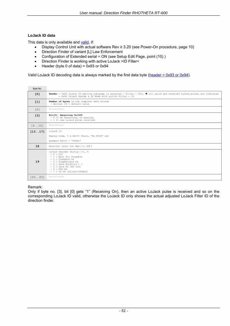
User manual Direction Finder RHOTHETA RT-600
- 51 -
LoJack ID data
This data is only available and valid if Display Control Unit with actual software Rev ge 320 (see Power-On procedure page 10) Direction Finder of variant [L] Law Enforcement Configuration of Extended serial = ON (see Setup Edit Page point (10) ) Direction Finder is working with active LoJack gtID Filterlt Header (byte 0 of data) = 0x93 or 0x94
Valid LoJack ID decoding data is always marked by the first data byte (header = 0x93 or 0x94)
Byte No
[0] Header = 0x93 LoJack ID editing sub-page is selected Filter = VLU all valid and received LoJack pulses are indicated = 0x94 Lojack Decode amp DF Mode with active Filter = ID
[1] Number of bytes in the complete data stream - decimal 26 = default value
[2] Nonrelevant
[3] Bit[0] Receiving OnOff - 0 =gt No Receiving no bearing - 1 =gt new LoJack pulse received
[412] Nonrelevant
[1317] Lojack ID
Replay Code 5 x ASCII Chars ldquoNo BIOZrdquo set
Example ASCII = ldquo000R1rdquo
18 Receiver Level Out Max [099]
19
LoJack Decoder Status [07] - 0 Off - 1 Wait for Preamble - 2 Preamble Ok - 3 FlagPattern Ok - 4 Data BitError gt 1 - 5 Data Ok (No VLU) - 6 VLU Ok - 7 ID Ok (Filter=IDONLY)
[2025] Nonrelevant
Remark Only if byte no [3] bit [0] gets ldquo1rdquo (Receiving On) then an active LoJack pulse is received and so on the corresponding LoJack ID valid otherwise the LoJack ID only shows the actual adjusted LoJack Filter ID of the direction finder
User manual Direction Finder RHOTHETA RT-600
- 52 -
635 Optional serial input (protocol description)
Specification serial input (optional)
The serial input is normally used for service and maintenance only Nevertheless it is possible via this interface to remote control the actual frequency and the squelchlevel of the DF system If a valid data stream is send to the DF then the actual frequency selection at the DCU is switched to Block2 AUX0 At this memory channel the new frequency is stored and used automatically (Refer to the chapter Frequency Selection Page) If the frequency is changed (by one valid data stream) no more serial input is necessary The actual frequency can be changed again at any time by manual operation at the DCU The timing of serial input (if used) is strictly fixed The optional serial input has to take place directly after a complete serial output (max 50 ms delay time) If a new changed frequency is commanded to the DCU via this serial input interface it can take up to 1 sec of time until this new frequency is ready for operationbearing It is strictly not recommended to use the frequency remote control for any scan mode The frequency control has to be used for static frequency change only Register of databytes
byte no
[0] Header 0xC0
[1] Number of bytes in the complete message (including header and checksumbyte)
[23] (not used for normal operation any byte values allowed)
[4] Volume [0100]
[58] Frequency [Hz] (frequency is rounded to the according grid automatically)
Valid Range for Standard Version Valid Range for LE Version
118000000 hellip 123000000 [Hz] 8333 kHz 118000000 hellip 123000000 [Hz] 8333 kHz
156050000 hellip 162025000 [Hz] 5000 kHz 164000000 hellip 174000000 [Hz] 8333 kHz
201000000 hellip 215995000 [Hz] 5000 kHz
240000000 hellip 246000000 [Hz] 8333 kHz 216000000 hellip 218995000 [Hz] 12500 kHz219000000 hellip 220000000 [Hz] 10000 kHz
400000000 hellip 410000000 [Hz] 8333 kHz 400000000 hellip 410000000 [Hz] 8333 kHz
[9] Squelchlevel Manual = [0hellip60] Autosql= [ -1] Warning use only for pulsed signals (as example CpSarsat LoJack)
[10] (not used for normal operation any byte values allowed)
[11] Internal Dimming [0100]
[12] Checksum is the 2rsquos complement of the modulo-256 sum of all bytes without checksum-byte [0n-1]
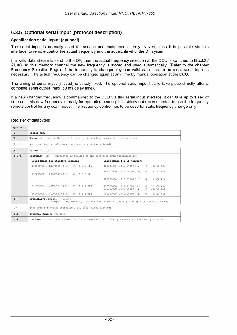
User manual Direction Finder RHOTHETA RT-600
- 52 -
635 Optional serial input (protocol description)
Specification serial input (optional)
The serial input is normally used for service and maintenance only Nevertheless it is possible via this interface to remote control the actual frequency and the squelchlevel of the DF system If a valid data stream is send to the DF then the actual frequency selection at the DCU is switched to Block2 AUX0 At this memory channel the new frequency is stored and used automatically (Refer to the chapter Frequency Selection Page) If the frequency is changed (by one valid data stream) no more serial input is necessary The actual frequency can be changed again at any time by manual operation at the DCU The timing of serial input (if used) is strictly fixed The optional serial input has to take place directly after a complete serial output (max 50 ms delay time) If a new changed frequency is commanded to the DCU via this serial input interface it can take up to 1 sec of time until this new frequency is ready for operationbearing It is strictly not recommended to use the frequency remote control for any scan mode The frequency control has to be used for static frequency change only Register of databytes
byte no
[0] Header 0xC0
[1] Number of bytes in the complete message (including header and checksumbyte)
[23] (not used for normal operation any byte values allowed)
[4] Volume [0100]
[58] Frequency [Hz] (frequency is rounded to the according grid automatically)
Valid Range for Standard Version Valid Range for LE Version
118000000 hellip 123000000 [Hz] 8333 kHz 118000000 hellip 123000000 [Hz] 8333 kHz
156050000 hellip 162025000 [Hz] 5000 kHz 164000000 hellip 174000000 [Hz] 8333 kHz
201000000 hellip 215995000 [Hz] 5000 kHz
240000000 hellip 246000000 [Hz] 8333 kHz 216000000 hellip 218995000 [Hz] 12500 kHz219000000 hellip 220000000 [Hz] 10000 kHz
400000000 hellip 410000000 [Hz] 8333 kHz 400000000 hellip 410000000 [Hz] 8333 kHz
[9] Squelchlevel Manual = [0hellip60] Autosql= [ -1] Warning use only for pulsed signals (as example CpSarsat LoJack)
[10] (not used for normal operation any byte values allowed)
[11] Internal Dimming [0100]
[12] Checksum is the 2rsquos complement of the modulo-256 sum of all bytes without checksum-byte [0n-1]