User Manual ARK-2121F - Advantechadvdownload.advantech.com/productfile/Downloadfile... · ARK-2121F...
58
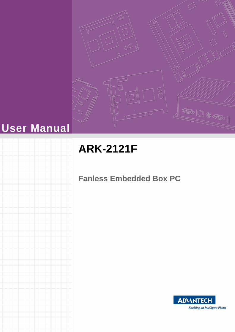
User Manual ARK-2121F Fanless Embedded Box PC
Transcript of User Manual ARK-2121F - Advantechadvdownload.advantech.com/productfile/Downloadfile... · ARK-2121F...
User Manual
ARK-2121F
Fanless Embedded Box PC

Attention!Please note:
This package contains a hard-copy user manual in Chinese for China CCC certification purposes, and please download the latest English user manual and driver on below website: http://www2.advantech.com/products/ark-2000_series_embedded_box_pcs/ark-2121f/mod_eb8fd822-1cca-4006-8ac1-def225eb4f59.aspx. Please disregard the Chinese hard copy user manual if the product is not to be sold and/or installed in China.
甲類警語:
警告使用者:這是甲類資訊產品,在居住的環境中使用時,可能會造成射頻干擾,在這種情況下,使用者會被要求採取某些適當對策。
ARK-2121F User Manual ii

CopyrightThe documentation and the software included with this product are copyrighted 2015by Advantech Co., Ltd. All rights are reserved. Advantech Co., Ltd. reserves the rightto make improvements in the products described in this manual at any time withoutnotice.
No part of this manual may be reproduced, copied, translated or transmitted in anyform or by any means without the prior written permission of Advantech Co., Ltd.Information provided in this manual is intended to be accurate and reliable. However,Advantech Co., Ltd. assumes no responsibility for its use, nor for any infringementsof the rights of third parties, which may result from its use.
AcknowledgementsAward is a trademark of Award Software International, Inc.
VIA is a trademark of VIA Technologies, Inc.
IBM, PC/AT, PS/2 and VGA are trademarks of International Business Machines Cor-poration.
Intel® and Pentium® are trademarks of Intel Corporation.
Microsoft Windows® is a registered trademark of Microsoft Corp.
RTL is a trademark of Realtek Semi-Conductor Co., Ltd.
ESS is a trademark of ESS Technology, Inc.
UMC is a trademark of United Microelectronics Corporation.
SMI is a trademark of Silicon Motion, Inc.
Creative is a trademark of Creative Technology LTD.
CHRONTEL is a trademark of Chrontel Inc.
All other product names or trademarks are properties of their respective owners.
For more information about this and other Advantech products, please visit our web-site at:
http://www.advantech.com/
http://www.advantech.com/ePlatform/
For technical support and service, please visit our support website at:
http://support.advantech.com.tw/support/
Part No. 2006K21270 Edition 1
Printed in China September 2015
iii ARK-2121F User Manual
Product Warranty (2 years)Advantech warrants to you, the original purchaser, that each of its products will befree from defects in materials and workmanship for two years from the date of pur-chase.
This warranty does not apply to any products which have been repaired or altered bypersons other than repair personnel authorized by Advantech, or which have beensubject to misuse, abuse, accident or improper installation. Advantech assumes noliability under the terms of this warranty as a consequence of such events.
Because of Advantech’s high quality-control standards and rigorous testing, most ofour customers never need to use our repair service. If an Advantech product is defec-tive, it will be repaired or replaced at no charge during the warranty period. For out-of-warranty repairs, you will be billed according to the cost of replacement materials,service time and freight. Please consult your dealer for more details.
If you think you have a defective product, follow these steps:
1. Collect all the information about the problem encountered. (For example, CPU speed, Advantech products used, other hardware and software used, etc.) Note anything abnormal and list any onscreen messages you get when the problem occurs.
2. Call your dealer and describe the problem. Please have your manual, product, and any helpful information readily available.
3. If your product is diagnosed as defective, obtain an RMA (return merchandise authorization) number from your dealer. This allows us to process your return more quickly.
4. Carefully pack the defective product, a fully-completed Repair and Replacement Order Card and a photocopy proof of purchase date (such as your sales receipt) in a shippable container. A product returned without proof of the purchase date is not eligible for warranty service.
5. Write the RMA number visibly on the outside of the package and ship it prepaid to your dealer.
Declaration of Conformity
FCC Class A
Note: This equipment has been tested and found to comply with the limits for a ClassA digital device, pursuant to part 15 of the FCC Rules. These limits are designed toprovide reasonable protection against harmful interference when the equipment isoperated in a commercial environment. This equipment generates, uses, and canradiate radio frequency energy and, if not installed and used in accordance with theinstruction manual, may cause harmful interference to radio communications. Opera-tion of this equipment in a residential area is likely to cause harmful interference inwhich case the user will be required to correct the interference at his own expense.
ARK-2121F User Manual iv

Technical Support and Assistance1. Visit the Advantech web site at www.advantech.com/support where you can find
the latest information about the product.2. Contact your distributor, sales representative, or Advantech's customer service
center for technical support if you need additional assistance. Please have the following information ready before you call:– Product name and serial number– Description of your peripheral attachments– Description of your software (operating system, version, application software,
etc.)– A complete description of the problem– The exact wording of any error messages
Warnings, Cautions and Notes
Packing ListBefore installation, please ensure the following items have been shipped:
1 x ARK-2121F unit 1 x Registration and 2 years Warranty card 1 x China RoHS 1 x 2-Pole Phoenix to DC-Jack Power cable 1 x SUSIAccess Utility CD 1 x Simplified Chinese manual
Warning! Warnings indicate conditions, which if not observed, can cause personal injury!
Caution! Cautions are included to help you avoid damaging hardware or losing data. e.g.
There is a danger of a new battery exploding if it is incorrectly installed. Do not attempt to recharge, force open, or heat the battery. Replace the battery only with the same or equivalent type recommended by the man-ufacturer. Discard used batteries according to the manufacturer's instructions.
Note! Notes provide optional additional information.
v ARK-2121F User Manual
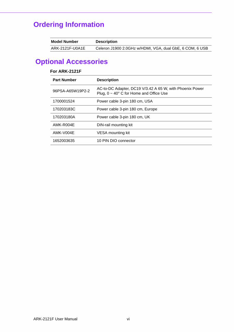
Ordering Information
Optional AccessoriesFor ARK-2121F
Model Number Description
ARK-2121F-U0A1E Celeron J1900 2.0GHz w/HDMI, VGA, dual GbE, 6 COM, 6 USB
Part Number Description
96PSA-A65W19P2-2AC-to-DC Adapter, DC19 V/3.42 A 65 W, with Phoenix Power Plug, 0 ~ 40° C for Home and Office Use
1700001524 Power cable 3-pin 180 cm, USA
170203183C Power cable 3-pin 180 cm, Europe
170203180A Power cable 3-pin 180 cm, UK
AMK-R004E DIN-rail mounting kit
AMK-V004E VESA mounting kit
1652003635 10 PIN DIO connector
ARK-2121F User Manual vi

Safety Instructions1. Please read these safety instructions carefully.2. Please keep this User’s Manual for later reference.3. Please disconnect this equipment from AC outlet before cleaning. Use a damp
cloth. Don’t use liquid or sprayed detergent for cleaning. Use moisture sheet or clothe for cleaning.
4. For pluggable equipment, the socket-outlet shall near the equipment and shall be easily accessible.
5. Please keep this equipment from humidity.6. Lay this equipment on a reliable surface when install. A drop or fall could cause
injury.7. The openings on the enclosure are for air convection hence protecting the
equipment from overheating. DO NOT COVER THE OPENINGS.8. Make sure the voltage of the power source when connecting the equipment to
the power outlet.9. Place the power cord such a way that people cannot step on it. Do not place
anything over the power cord. 10. All cautions and warnings on the equipment should be noted.11. If the equipment is not used for long time, disconnect the equipment from mains
to avoid being damaged by transient over-voltage.12. Never pour any liquid into ventilation openings; this could cause fire or electrical
shock.13. Never open the equipment. For safety reasons, only qualified service personnel
should open the equipment.14. If one of the following situations arises, get the equipment checked by service
personnel:The power cord or plug is damaged.Liquid has penetrated into the equipment.The equipment has been exposed to moisture.The equipment does not work well, or you cannot get it to work according to
the user's manual.The equipment has been dropped and damaged.The equipment has obvious signs of breakage.
15. Do not leave this equipment in an environment where the storage temperature may go below -40° C (-40° F) or above 85° C (185° F). This could damage the equipment. the equipment should be in a controlled environment.
16. Caution: Danger of explosion if battery is incorrectly replaced. Replace only with the same or equivalent type recommended by the manufacturer, discard used batteries according to the manufacturer's instructions.
17. The sound pressure level at the operator's position according to IEC 704-1:1982 is no more than 70 dB (A).
18. RESTRICTED ACCESS AREA: The equipment should only be installed in a Restricted Access Area.
19. DISCLAIMER: This set of instructions is given according to IEC 704-1. Advan-tech disclaims all responsibility for the accuracy of any statements contained herein.
vii ARK-2121F User Manual

ARK-2121F User Manual viii

Contents
Chapter 1 General Introduction ...........................11.1 Introduction ............................................................................................... 21.2 Product Features....................................................................................... 3
1.2.1 General ......................................................................................... 31.2.2 Display .......................................................................................... 31.2.3 Ethernet ........................................................................................ 3
1.3 Chipset ...................................................................................................... 31.3.1 Functional Specification ................................................................ 31.3.2 iManager/SUSI 4.0........................................................................ 4
1.4 Mechanical Specifications......................................................................... 51.4.1 Dimensions ................................................................................... 5
Figure 1.1 ARK-2121F Mechanical dimension drawing............... 51.4.2 Weight........................................................................................... 5
1.5 Power Requirement .................................................................................. 51.5.1 System Power............................................................................... 51.5.2 RTC Battery .................................................................................. 5
1.6 Environment Specification......................................................................... 61.6.1 Operating Temperature................................................................. 61.6.2 Relative Humidity .......................................................................... 61.6.3 Storage Temperature.................................................................... 61.6.4 Vibration during Operation ............................................................ 61.6.5 Shock during Operation ................................................................ 61.6.6 Safety............................................................................................ 61.6.7 EMC.............................................................................................. 6
Chapter 2 H/W Installation....................................72.1 Introduction ............................................................................................... 82.2 Jumpers .................................................................................................... 8
2.2.1 Jumper Description ....................................................................... 82.2.2 Jumper List ................................................................................... 9
Table 2.1: Jumper List of Main Board.......................................... 92.2.3 Jumper Location ........................................................................... 9
Figure 2.1 Jumper Layout............................................................ 92.2.4 Jumper Setting.............................................................................. 9
2.3 Connectors.............................................................................................. 102.3.1 ARK-2121F External I/O Connectors.......................................... 10
Figure 2.2 ARK-2121F IO connectors drawing.......................... 10Figure 2.3 COM connector ........................................................ 11Table 2.2: COM Connector Pin Assignments............................ 11Figure 2.4 Ethernet connector ................................................... 12Table 2.3: Ethernet Connector Pin Assignments....................... 12Figure 2.5 Audio connector........................................................ 12Table 2.4: Audio Connector Pin Assignments ........................... 12Figure 2.6 USB connector ......................................................... 13Table 2.5: USB Connector......................................................... 13Figure 2.7 VGA Connector ........................................................ 13Table 2.6: VGA Connector Pin Assignments............................. 13Figure 2.8 Power Input Connector............................................. 14Table 2.7: Power connector Pin Assignments........................... 14Figure 2.9 Power Button ............................................................ 14Figure 2.10LED Indicators .......................................................... 14
2.4 Installation ............................................................................................... 162.4.1 HDD Installation .......................................................................... 16
ix ARK-2121F User Manual
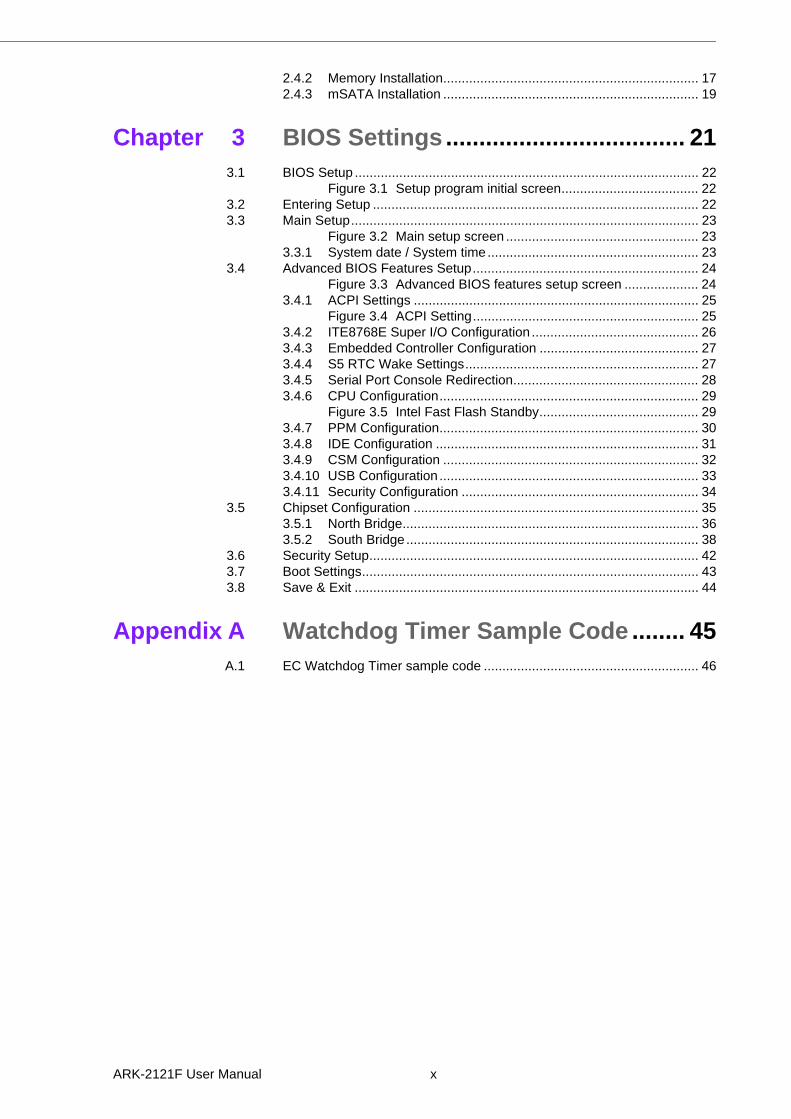
2.4.2 Memory Installation..................................................................... 172.4.3 mSATA Installation ..................................................................... 19
Chapter 3 BIOS Settings .................................... 213.1 BIOS Setup ............................................................................................. 22
Figure 3.1 Setup program initial screen..................................... 223.2 Entering Setup ........................................................................................ 223.3 Main Setup.............................................................................................. 23
Figure 3.2 Main setup screen .................................................... 233.3.1 System date / System time......................................................... 23
3.4 Advanced BIOS Features Setup............................................................. 24Figure 3.3 Advanced BIOS features setup screen .................... 24
3.4.1 ACPI Settings ............................................................................. 25Figure 3.4 ACPI Setting............................................................. 25
3.4.2 ITE8768E Super I/O Configuration ............................................. 263.4.3 Embedded Controller Configuration ........................................... 273.4.4 S5 RTC Wake Settings............................................................... 273.4.5 Serial Port Console Redirection.................................................. 283.4.6 CPU Configuration...................................................................... 29
Figure 3.5 Intel Fast Flash Standby........................................... 293.4.7 PPM Configuration...................................................................... 303.4.8 IDE Configuration ....................................................................... 313.4.9 CSM Configuration ..................................................................... 323.4.10 USB Configuration ...................................................................... 333.4.11 Security Configuration ................................................................ 34
3.5 Chipset Configuration ............................................................................. 353.5.1 North Bridge................................................................................ 363.5.2 South Bridge............................................................................... 38
3.6 Security Setup......................................................................................... 423.7 Boot Settings........................................................................................... 433.8 Save & Exit ............................................................................................. 44
Appendix A Watchdog Timer Sample Code ........ 45A.1 EC Watchdog Timer sample code .......................................................... 46
ARK-2121F User Manual x

Chapter 1
1 General IntroductionThis chapter gives background information on ARK-2121F series.
1.1 Introduction
ARK-2121F, an intelligent, fanless embedded system powered by Intel® Celeron™J1900 Quad Core low power processor with multiple I/O interface. The new genera-
tion Intel® Celeron™ processor brings 300% improvement on processing power and
300% on graphics performance than previous generation Intel® Atom™ processors.These low-power platforms provide energy-efficient and environmentally responsiblesolutions, and serve applications targeted at factory automation, machine automa-tion, kiosks, and self-service applications; and they operate reliably in -20 ~ 70° Cenvironments!
Rugged & Multifunctional Design
ARK-2121F is powered by Intel® Celeron™ J1900 2.0GHz Quad core processors inan Advantech, rugged-design embedded box PC. All models are fanless, and high-light various quality features including wide-input power supplies from 9-36VDC, widetemperature range -20 ~ 70° C, diverse expandability options, and structuralstrengthening. ARK-2121F enlarges the surface of the top cover and conductive cyl-inder to create maximum cooling effects for optimized cooling efficiency. It also pro-vides rich I/O interfaces: up to 6 x USB, 2 x GbE, 6 x COM, and supports highcapacity 2.5” HDD up to 1 TB. The RS-232/422/485 COM port mode can easily bechanged via BIOS setting.
Multiple Display Support
ARK-2121F supports two display types: VGA, HDMI display. The graphic engine isDirectX 11.1, H/W format decode/Acceleration, MPEG2 (H/W acceleration), H.264/VC1/ WMV9 (H/W Decode/Acceleration). ARK-2121F supports dual independent dis-play.
Built in Intelligent Management Tools - Advantech iManager & SUSIAccess
Advantech iManager/SUSI 4.0 provides a valuable suite of programmable APIs suchas multi-level watchdog, hardware monitor, system restore, and other user-friendlyinterface. iManager is an intelligent self-management cross platform tool that moni-tors system status for problems and takes action if anything is abnormal. iManager/SUSI 4.0 offers a boot up guarantee in critical, low temperature environments so sys-tems can automatically recover when voltages dip. iManager/SUSI 4.0 makes thewhole system more reliable and more intelligent. ARK-2121F also supports Advan-tech’s own SUSIAccess, which provides easy remote management so users canmonitor, configure, and control a large number of terminals to make maintenance andsystem recovery simpler.
ARK-2121F User Manual 2
Chapter 1
GeneralIntroduction
1.2 Product Features
1.2.1 General
CPU: Intel® Celeron™ Processor J1900 2.0GHz
System Chipset: Intel® Celeron J1900 SOC BIOS: AMI 16 Mbit Flash BIOS System Memory: One DDR3L SODIMM. DDR3L 1333MHz up to 8 GB Watchdog Timer: Single chip Watchdog 255-level interval timer, setup by soft-
ware I/O Interface: 2 x RS232, 6 x RS232/422/485 USB: 5 x USB 2.0, 1 x USB 3.0, 1 x internal USB 2.0 for security dongle Audio: High Definition Audio (HD), Line-in, Line out, Mic-in Storage: 1 x mSATA and 1 x high capacity 2.5” SATA HDD (up to 12.5mm
height) Expansion Interface:
– Supports 2 x Full Size MiniPCIe (1 with SIM holder) Software API: Advantech iManager/SUSI 4.0 and SUSIAccess - Remote
Device Management technology
1.2.2 Display
Controller: Intel® Celeron J1900 Resolution:
– VGA: Supports up to 2048 x 1152– HDMI: Supports up to 1080P @ 60Hz,Supports HDMI 1.4a
Dual Display: VGA+HDMI
1.2.3 Ethernet Chipset:
– LAN1 Intel i210– LAN2 Intel i210
Speed: 1000 Mbps Interface: 2 x RJ45 Standard: Compliant with IEEE 802.3, IEEE 802.3u, IEEE 802.3x, IEEE 802.3y,
IEEE 802.ab.
1.3 Chipset
1.3.1 Functional Specification
1.3.1.1 Processor
Processor
Intel® Celeron™ Processor J1900
Intel® Celeron™ J1900 at 2.0GHz, with 2MB L2 Cache Manufacturing
Technology 22nm
MemorySupports DDR3L 1333MHz up to 8GB
1 x 204-pin SODIMM socket type
3 ARK-2121F User Manual

1.3.1.2 Chipset
1.3.1.3 Others
1.3.2 iManager/SUSI 4.0
Internal Graph-ics Features
DirectX 11.1 and OpenGL 3.0
Display Ports VGA + HDMI, HDMI 1.4a Supports HDCP 1.3
Video Accelera-tor
H/W accelerated video decode
Video decoder: Support MPEG4, VC1, WMV9, H.264 Supports DVD, Blu-ray, and HD video
SATA Interface
Supports several optional sections of Serial ATA II: Extensions to Serial ATA 1.0 Specification, Revision 1.0
Supports SATA transfers to 300 Mbytes/sec. Supports mSATA socket
USB Interface
USB host interface with support for 1 USB 3.0, 5 USB 2.0 ports and 1 x USB 2.0 internal security dongle
All ports are High-Speed, Full-Speed, and Low-Speed capable Supports legacy keyboard/mouse software
BIOS AMI 64 Mb Flash BIOS via SPI
Serial ports
COM1 ~ COM6: Supports RS-232/422/485 and change mode under BIOS setting
COM connector: D-SUB CON. 9P
Ethernet
LAN1 Intel i210, LAN2 Intel i210 Compliant with IEEE 802.3, IEEE 802.3u, IEEE 802.3x, IEEE 802.3y,
IEEE 802.ab. Support 10/100/1000 Mbps.LAN Connectors: Phone Jack RJ45 8P 90D(F)
Audio
Audio Codec: Realtek ALC888S: Compliant with HD Audio specifications Supports 16/20/24-bit DAC and 16/20/24-bit ADC resolution Supports: Line-out, Line-in, Mic-inAudio Connectors: Ear Phone Jack * 3
Battery backup BATTERY 3V/210 mAh with WIRE x 1
Sequence control Supported
Watchdog timer Multi Level WDT Programmable 1-255 sec / min
Hardware monitor CPU Temperature / input Current / input Voltage
Power saving Deep sleep S5 mode
System information Running HR / Boot record
ARK-2121F User Manual 4
Chapter 1
GeneralIntroduction
1.4 Mechanical Specifications
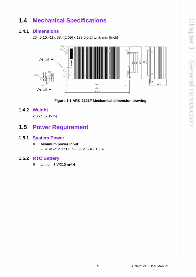
1.4.1 Dimensions264.5[10.41] x 68.4[2.69] x 133.0[5.2] Unit: mm [Inch]
Figure 1.1 ARK-2121F Mechanical dimension drawing
1.4.2 Weight2.3 kg (5.06 lb)
1.5 Power Requirement
1.5.1 System Power Minimum power input:
– ARK-2121F: DC 9 - 36 V, 5 A - 1.2 A
1.5.2 RTC Battery Lithium 3 V/210 mAH
78.5
72.5
102.
5
84.5
4
Ø4
Ø2.5
133
6
Detail A
Ø4,6 5.0
14.0
8,0
264,5
238,2
252,5
Detail A
68.39
133
3.5
5 ARK-2121F User Manual
1.6 Environment Specification
1.6.1 Operating Temperature With Industrial Grade SSD/mSATA: -20 ~ 70° C (-4~158° F), with air flow,
speed=0.7 m/sec With 2.5-inch hard disk 0 to 45° C (32~113° F), with air flow, speed=0.7 m/sec
1.6.2 Relative Humidity 95% @ 40° C (non-condensing)
1.6.3 Storage Temperature -40 ~ 85° C (-40 ~ 185° F)
1.6.4 Vibration during Operation When the system is equipped with SSD/mSATA: 3Grms, IEC 60068-2-64, ran-
dom, 5 ~ 500 Hz, 1hr/axis, x,y,z 3 axes.
1.6.5 Shock during Operation When the system is equipped with SSD/mSATA: 30G, IEC 60068-2-27, half
sine, 11 ms duration.
1.6.6 Safety UL, CB, CCC, BSMI
1.6.7 EMC CE, FCC, CCC, BSMI
ARK-2121F User Manual 6

Chapter 2
2 H/W InstallationThis chapter introduces external IO and the installation of ARK-2121F hardware.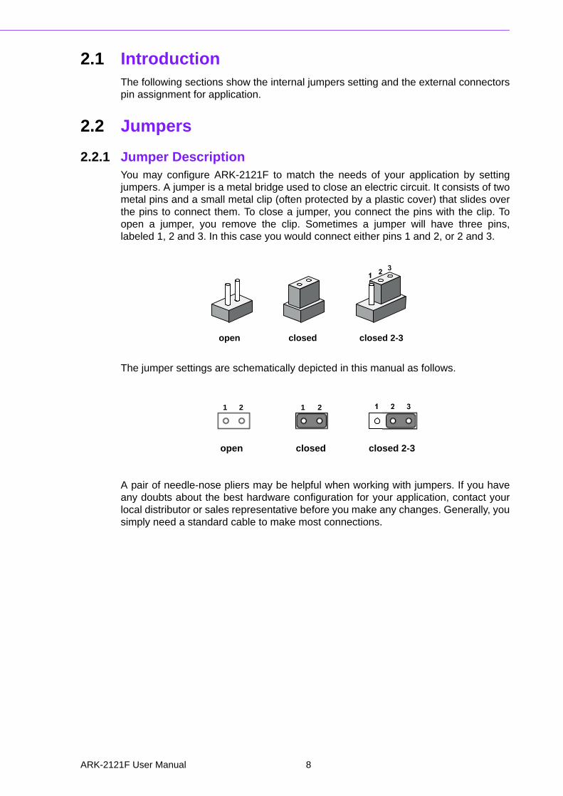
2.1 IntroductionThe following sections show the internal jumpers setting and the external connectorspin assignment for application.
2.2 Jumpers
2.2.1 Jumper DescriptionYou may configure ARK-2121F to match the needs of your application by settingjumpers. A jumper is a metal bridge used to close an electric circuit. It consists of twometal pins and a small metal clip (often protected by a plastic cover) that slides overthe pins to connect them. To close a jumper, you connect the pins with the clip. Toopen a jumper, you remove the clip. Sometimes a jumper will have three pins,labeled 1, 2 and 3. In this case you would connect either pins 1 and 2, or 2 and 3.
The jumper settings are schematically depicted in this manual as follows.
A pair of needle-nose pliers may be helpful when working with jumpers. If you haveany doubts about the best hardware configuration for your application, contact yourlocal distributor or sales representative before you make any changes. Generally, yousimply need a standard cable to make most connections.
closed 2-3closedopen
1 2 1 2
closed 2-3closedopen
ARK-2121F User Manual 8
Chapter 2
H/W
Installation
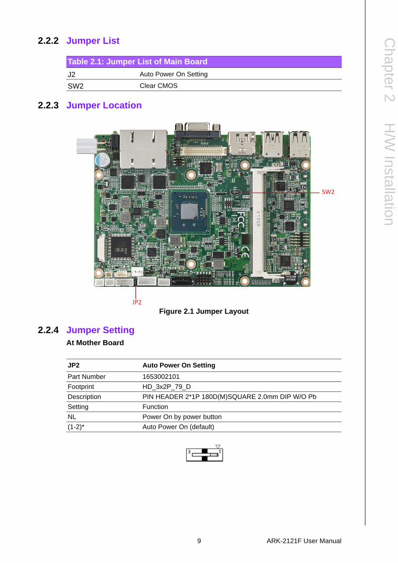
2.2.2 Jumper List
2.2.3 Jumper Location
Figure 2.1 Jumper Layout
2.2.4 Jumper SettingAt Mother Board
Table 2.1: Jumper List of Main Board
J2 Auto Power On Setting
SW2 Clear CMOS
JP2 Auto Power On Setting
Part Number 1653002101
Footprint HD_3x2P_79_D
Description PIN HEADER 2*1P 180D(M)SQUARE 2.0mm DIP W/O Pb
Setting Function
NL Power On by power button
(1-2)* Auto Power On (default)
9 ARK-2121F User Manual
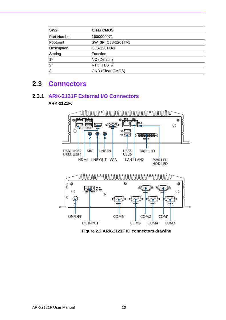
2.3 Connectors
2.3.1 ARK-2121F External I/O ConnectorsARK-2121F:
Figure 2.2 ARK-2121F IO connectors drawing
SW2 Clear CMOS
Part Number 1600000071
Footprint SW_3P_CJS-1201TA1
Description CJS-1201TA1
Setting Function
1* NC (Default)
2 RTC_TEST#
3 GND (Clear CMOS)
ARK-2121F User Manual 10
Chapter 2
H/W
Installation
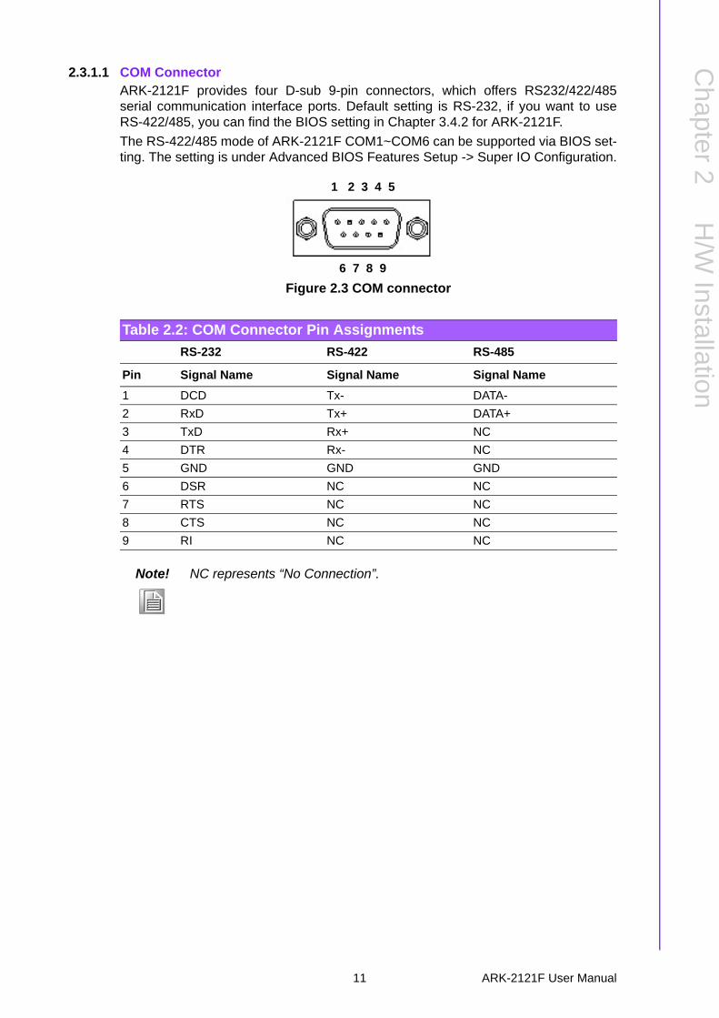
2.3.1.1 COM ConnectorARK-2121F provides four D-sub 9-pin connectors, which offers RS232/422/485serial communication interface ports. Default setting is RS-232, if you want to useRS-422/485, you can find the BIOS setting in Chapter 3.4.2 for ARK-2121F.
The RS-422/485 mode of ARK-2121F COM1~COM6 can be supported via BIOS set-ting. The setting is under Advanced BIOS Features Setup -> Super IO Configuration.
Figure 2.3 COM connector
Table 2.2: COM Connector Pin Assignments
RS-232 RS-422 RS-485
Pin Signal Name Signal Name Signal Name
1 DCD Tx- DATA-
2 RxD Tx+ DATA+
3 TxD Rx+ NC
4 DTR Rx- NC
5 GND GND GND
6 DSR NC NC
7 RTS NC NC
8 CTS NC NC
9 RI NC NC
Note! NC represents “No Connection”.
1 2 3 4 5
6 7 8 9
11 ARK-2121F User Manual
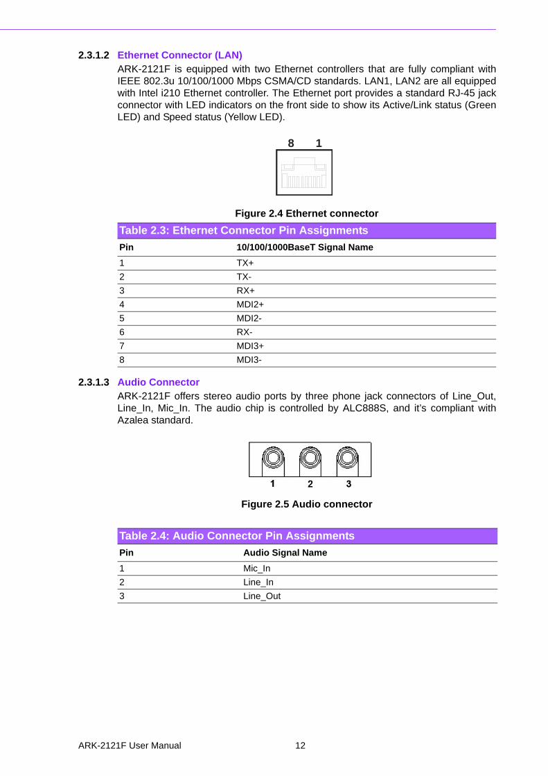
2.3.1.2 Ethernet Connector (LAN)ARK-2121F is equipped with two Ethernet controllers that are fully compliant withIEEE 802.3u 10/100/1000 Mbps CSMA/CD standards. LAN1, LAN2 are all equippedwith Intel i210 Ethernet controller. The Ethernet port provides a standard RJ-45 jackconnector with LED indicators on the front side to show its Active/Link status (GreenLED) and Speed status (Yellow LED).
Figure 2.4 Ethernet connector
2.3.1.3 Audio ConnectorARK-2121F offers stereo audio ports by three phone jack connectors of Line_Out,Line_In, Mic_In. The audio chip is controlled by ALC888S, and it’s compliant withAzalea standard.
Figure 2.5 Audio connector
Table 2.3: Ethernet Connector Pin Assignments
Pin 10/100/1000BaseT Signal Name
1 TX+
2 TX-
3 RX+
4 MDI2+
5 MDI2-
6 RX-
7 MDI3+
8 MDI3-
18
Table 2.4: Audio Connector Pin Assignments
Pin Audio Signal Name
1 Mic_In
2 Line_In
3 Line_Out
ARK-2121F User Manual 12
Chapter 2
H/W
Installation
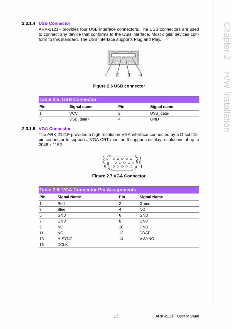
2.3.1.4 USB ConnectorARK-2121F provides four USB interface connectors. The USB connectors are usedto connect any device that conforms to the USB interface. Most digital devices con-form to this standard. The USB interface supports Plug and Play.
Figure 2.6 USB connector
2.3.1.5 VGA ConnectorThe ARK-2121F provides a high resolution VGA interface connected by a D-sub 15-pin connector to support a VGA CRT monitor. It supports display resolutions of up to2048 x 1152.
Figure 2.7 VGA Connector
Table 2.5: USB Connector
Pin Signal name Pin Signal name
1 VCC 2 USB_data-
3 USB_data+ 4 GND
Table 2.6: VGA Connector Pin Assignments
Pin Signal Name Pin Signal Name
1 Red 2 Green
3 Blue 4 NC
5 GND 6 GND
7 GND 8 GND
9 NC 10 GND
11 NC 12 DDAT
13 H-SYNC 14 V-SYNC
15 DCLK
13 ARK-2121F User Manual

2.3.1.6 Power Input ConnectorARK-2121F comes with a two pins header that carries 9 ~ 36 VDC external powerinput.
Figure 2.8 Power Input Connector
2.3.1.7 Power ON/OFF ButtonARK-2121F comes with a Power On/Off button, that supports dual functions of SoftPower -On/Off (Instant off or Delay 4 Second), and Suspend.
Figure 2.9 Power Button
2.3.1.8 LED IndicatorsThere are two LEDs on ARK-2121F front metal face plate for indicating system sta-tus: PWR LED is for power status; and HDD LED is for HDD & flash disk status.
Figure 2.10 LED Indicators
Table 2.7: Power connector Pin Assignments Pin Signal Name
1 GND
2 +9 - 36 VDC
12
ARK-2121F User Manual 14

Chapter 2
H/W
Installation
2.3.1.9 DIO Connector ARK-2121F offer 8 PIN Isolated DIO and 2 PIN Ground.
Type: 0~3 PIN; DI; 4~7 PIN DO: 8~9 PIN Ground.
Input Voltage: 0 to 30 VDC at 25 Hz
*Isolation level: 3kV
Digital Output levels for Wet contacts:
Logic Level 1: Close to GND Logic Level 0: Open
Digital Input Levels: for Wet contacts:
Logic level 0: +3 V max. Logic level 1: +5 V to +30V
Output Current: Max. 50 mA per channel.
15 ARK-2121F User Manual
2.4 Installation
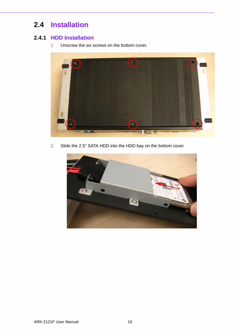
2.4.1 HDD Installation1. Unscrew the six screws on the bottom cover.
2. Slide the 2.5" SATA HDD into the HDD bay on the bottom cover.
ARK-2121F User Manual 16
Chapter 2
H/W
Installation
3. Screw the four screws on the side of HDD bracket. The screws are used to fix the HDD on the bracket. (The screws are in the accessory box.)
4. Recover the bottom cover and screws.
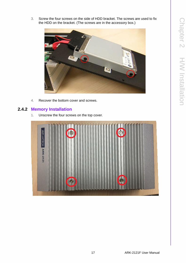
2.4.2 Memory Installation1. Unscrew the four screws on the top cover.
17 ARK-2121F User Manual
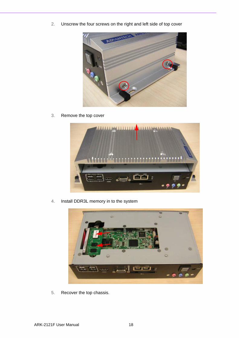
2. Unscrew the four screws on the right and left side of top cover
3. Remove the top cover
4. Install DDR3L memory in to the system
5. Recover the top chassis.
ARK-2121F User Manual 18

Chapter 2
H/W
Installation
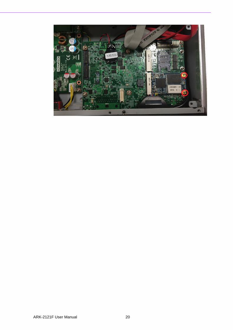
2.4.3 mSATA Installation1. Unscrew the six screws on the bottom cover.
2. Put the mSATA module in mSATA slot (CN16)
3. Screw 2 screws on the mSATA module.
19 ARK-2121F User Manual
ARK-2121F User Manual 20
Chapter 3
3 BIOS Settings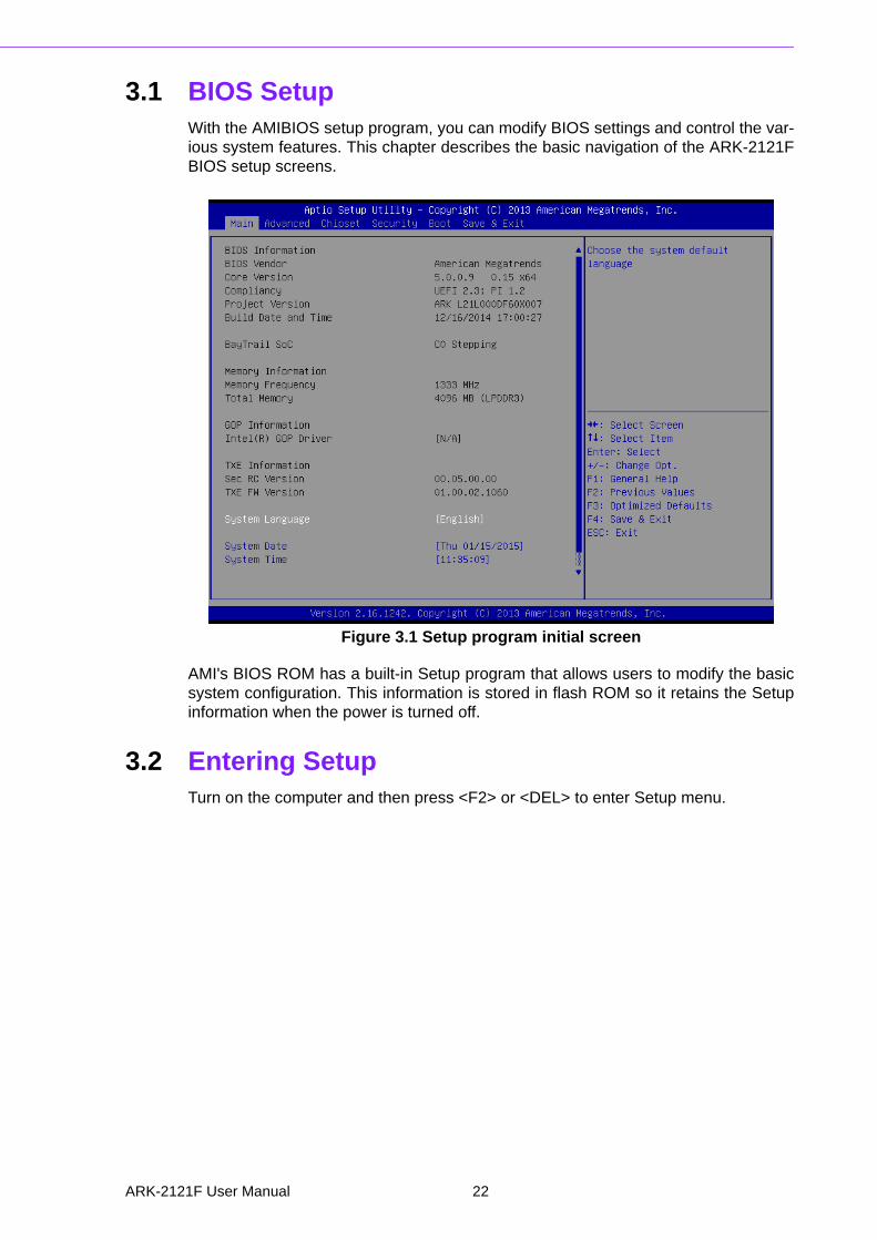
3.1 BIOS SetupWith the AMIBIOS setup program, you can modify BIOS settings and control the var-ious system features. This chapter describes the basic navigation of the ARK-2121FBIOS setup screens.
Figure 3.1 Setup program initial screen
AMI's BIOS ROM has a built-in Setup program that allows users to modify the basicsystem configuration. This information is stored in flash ROM so it retains the Setupinformation when the power is turned off.
3.2 Entering Setup Turn on the computer and then press <F2> or <DEL> to enter Setup menu.
ARK-2121F User Manual 22
Chapter 3
BIO
S S
ettings
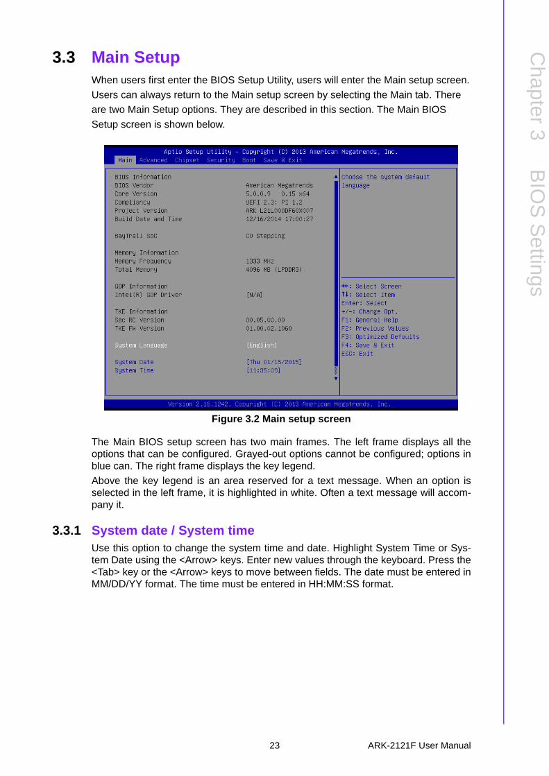
3.3 Main Setup When users first enter the BIOS Setup Utility, users will enter the Main setup screen.
Users can always return to the Main setup screen by selecting the Main tab. There
are two Main Setup options. They are described in this section. The Main BIOS
Setup screen is shown below.
Figure 3.2 Main setup screen
The Main BIOS setup screen has two main frames. The left frame displays all theoptions that can be configured. Grayed-out options cannot be configured; options inblue can. The right frame displays the key legend.
Above the key legend is an area reserved for a text message. When an option isselected in the left frame, it is highlighted in white. Often a text message will accom-pany it.
3.3.1 System date / System timeUse this option to change the system time and date. Highlight System Time or Sys-tem Date using the <Arrow> keys. Enter new values through the keyboard. Press the<Tab> key or the <Arrow> keys to move between fields. The date must be entered inMM/DD/YY format. The time must be entered in HH:MM:SS format.
23 ARK-2121F User Manual

3.4 Advanced BIOS Features Setup Select the Advanced tab from the ARK-2121F setup screen to enter the AdvancedBIOS Setup screen. You can select any of the items in the left frame of the screen,such as CPU Configuration, to go to the sub menu for that item. You can display anAdvanced BIOS Setup option by highlighting it using the <Arrow> keys. All AdvancedBIOS Setup options are described in this section. The Advanced BIOS Setupscreens are shown below. The sub menus are described on the following pages.
Figure 3.3 Advanced BIOS features setup screen
ARK-2121F User Manual 24

Chapter 3
BIO
S S
ettings
3.4.1 ACPI Settings
Figure 3.4 ACPI Setting
Enable ACPI Auto ConfigurationThis item allows users to enable or disable BIOS ACPI auto configuration.
Enable HibernationThis item allows users to enable or disable hibernation.
ACPI Sleep StateThis item allows users to set the ACPI sleep state.
Lock Legacy ResourcesThis item allows users to lock legacy devices' resources.
25 ARK-2121F User Manual

3.4.2 ITE8768E Super I/O Configuration
Serial Port 1 ConfigurationSet Parameters of Serial Port 1 (COMA).
Serial Port 2 ConfigurationSet Parameters of Serial Port 2 (COMB).
Serial Port 3 ConfigurationSet Parameters of Serial Port 3 (COMC).
Serial Port 4 ConfigurationSet Parameters of Serial Port 4 (COMD).
ARK-2121F User Manual 26
Chapter 3
BIO
S S
ettings
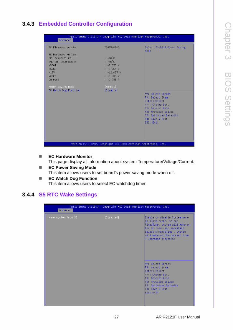
3.4.3 Embedded Controller Configuration
EC Hardware MonitorThis page display all information about system Temperature/Voltage/Current.
EC Power Saving ModeThis item allows users to set board’s power saving mode when off.
EC Watch Dog FunctionThis item allows users to select EC watchdog timer.
3.4.4 S5 RTC Wake Settings
27 ARK-2121F User Manual

Wake system from S5Enable or disable System wake on alarm event. Select FixedTime, system will wake on the hr:min:sec specified.
3.4.5 Serial Port Console Redirection
Console RedirectionThis item allows users to enable or disable console redirection for Microsoft Windows Emergency Management Services (EMS).
Console RedirectionThis item allows users to configuration console redirection detail settings.
ARK-2121F User Manual 28
Chapter 3
BIO
S S
ettings
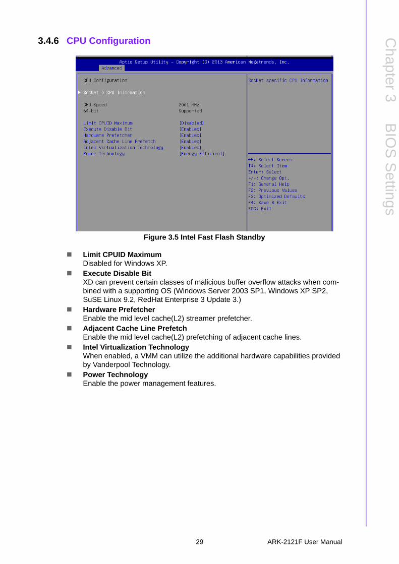
3.4.6 CPU Configuration
Figure 3.5 Intel Fast Flash Standby
Limit CPUID MaximumDisabled for Windows XP.
Execute Disable BitXD can prevent certain classes of malicious buffer overflow attacks when com-bined with a supporting OS (Windows Server 2003 SP1, Windows XP SP2, SuSE Linux 9.2, RedHat Enterprise 3 Update 3.)
Hardware PrefetcherEnable the mid level cache(L2) streamer prefetcher.
Adjacent Cache Line PrefetchEnable the mid level cache(L2) prefetching of adjacent cache lines.
Intel Virtualization TechnologyWhen enabled, a VMM can utilize the additional hardware capabilities provided by Vanderpool Technology.
Power TechnologyEnable the power management features.
29 ARK-2121F User Manual
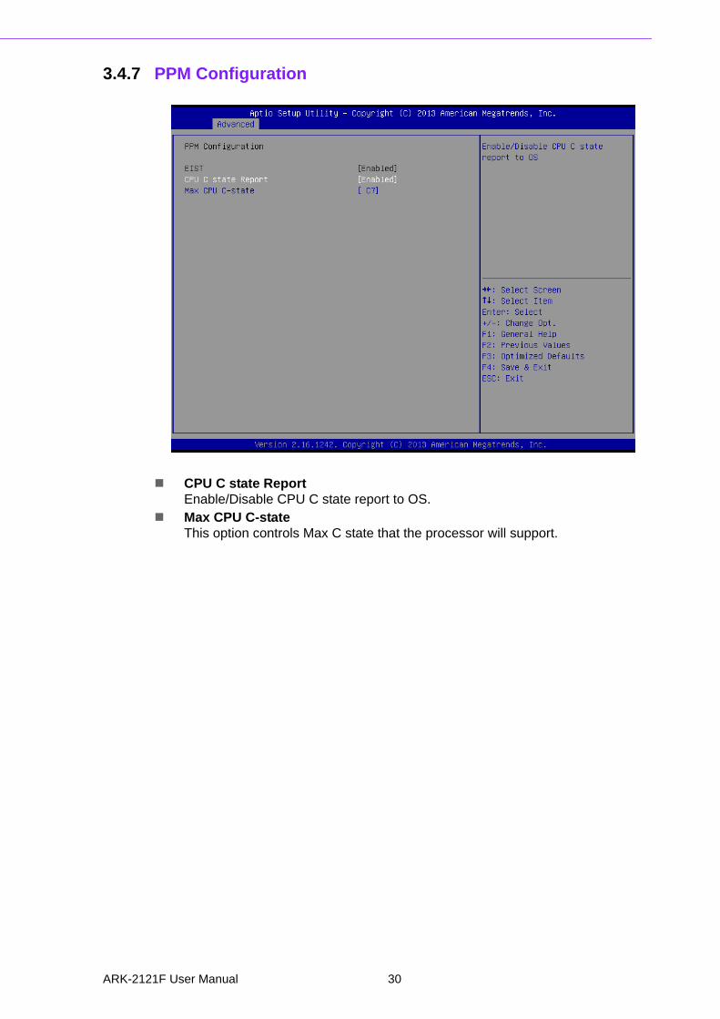
3.4.7 PPM Configuration
CPU C state ReportEnable/Disable CPU C state report to OS.
Max CPU C-stateThis option controls Max C state that the processor will support.
ARK-2121F User Manual 30
Chapter 3
BIO
S S
ettings
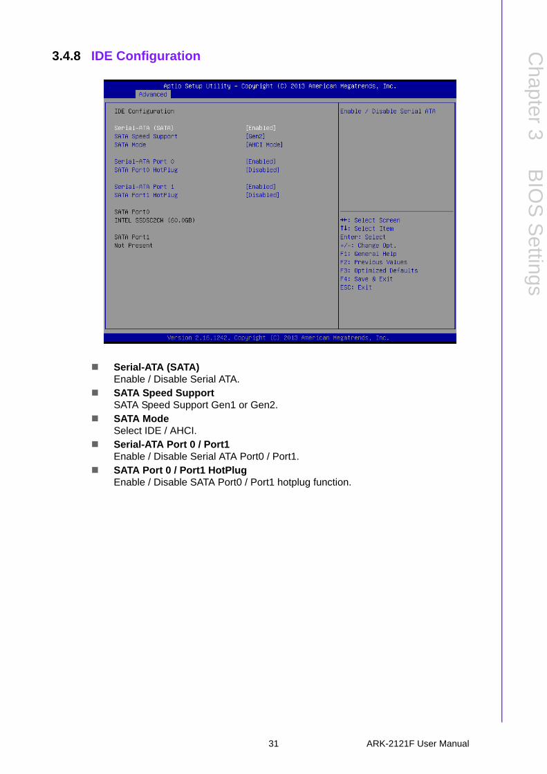
3.4.8 IDE Configuration
Serial-ATA (SATA)Enable / Disable Serial ATA.
SATA Speed SupportSATA Speed Support Gen1 or Gen2.
SATA ModeSelect IDE / AHCI.
Serial-ATA Port 0 / Port1Enable / Disable Serial ATA Port0 / Port1.
SATA Port 0 / Port1 HotPlugEnable / Disable SATA Port0 / Port1 hotplug function.
31 ARK-2121F User Manual
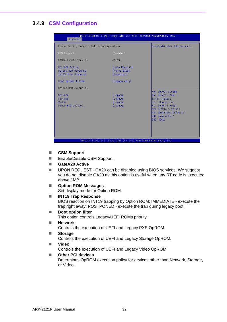
3.4.9 CSM Configuration
CSM Support Enable/Disable CSM Support. GateA20 Active UPON REQUEST - GA20 can be disabled using BIOS services. We suggest
you do not disable GA20 as this option is useful when any RT code is executed above 1MB.
Option ROM MessagesSet display mode for Option ROM.
INT19 Trap ResponseBIOS reaction on INT19 trapping by Option ROM: IMMEDIATE - execute the trap right away; POSTPONED - execute the trap during legacy boot.
Boot option filterThis option controls Legacy/UEFI ROMs priority.
NetworkControls the execution of UEFI and Legacy PXE OpROM.
StorageControls the execution of UEFI and Legacy Storage OpROM.
VideoControls the execution of UEFI and Legacy Video OpROM.
Other PCI devicesDetermines OpROM execution policy for devices other than Network, Storage, or Video.
ARK-2121F User Manual 32
Chapter 3
BIO
S S
ettings
3.4.10 USB Configuration
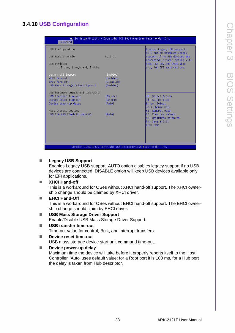
Legacy USB SupportEnables Legacy USB support. AUTO option disables legacy support if no USB devices are connected. DISABLE option will keep USB devices available only for EFI applications.
XHCI Hand-offThis is a workaround for OSes without XHCI hand-off support. The XHCI owner-ship change should be claimed by XHCI driver.
EHCI Hand-OffThis is a workaround for OSes without EHCI hand-off support. The EHCI owner-ship change should claim by EHCI driver.
USB Mass Storage Driver SupportEnable/Disable USB Mass Storage Driver Support.
USB transfer time-outTime-out value for control, Bulk, and interrupt transfers.
Device reset time-outUSB mass storage device start unit command time-out.
Device power-up delayMaximum time the device will take before it properly reports itself to the Host Controller. 'Auto' uses default value: for a Root port it is 100 ms, for a Hub port the delay is taken from Hub descriptor.
33 ARK-2121F User Manual
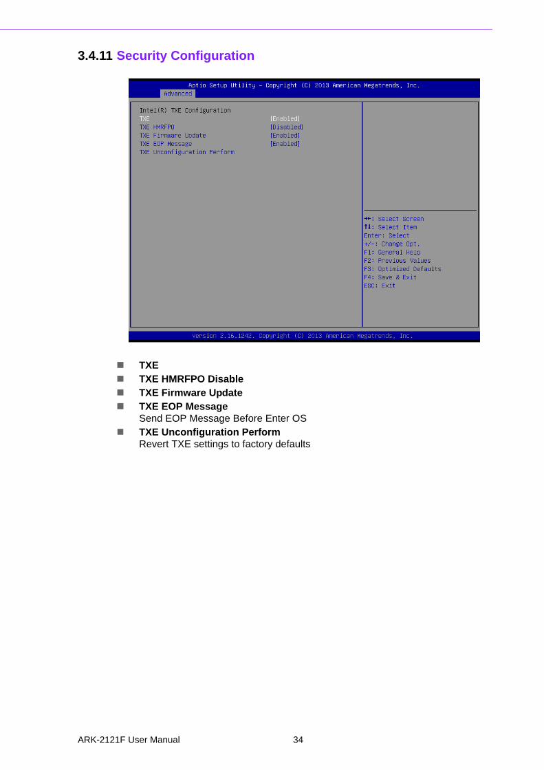
3.4.11 Security Configuration
TXE TXE HMRFPO Disable TXE Firmware Update TXE EOP Message
Send EOP Message Before Enter OS TXE Unconfiguration Perform
Revert TXE settings to factory defaults
ARK-2121F User Manual 34
Chapter 3
BIO
S S
ettings
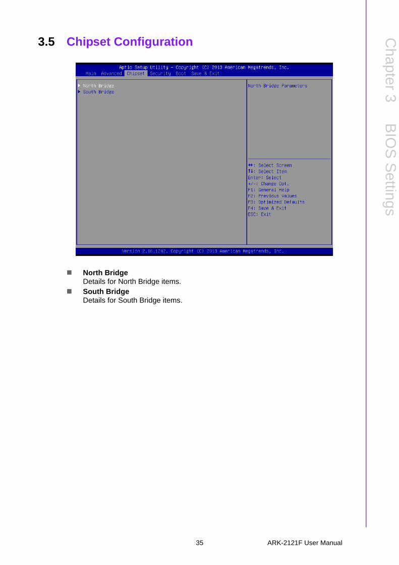
3.5 Chipset Configuration
North BridgeDetails for North Bridge items.
South BridgeDetails for South Bridge items.
35 ARK-2121F User Manual
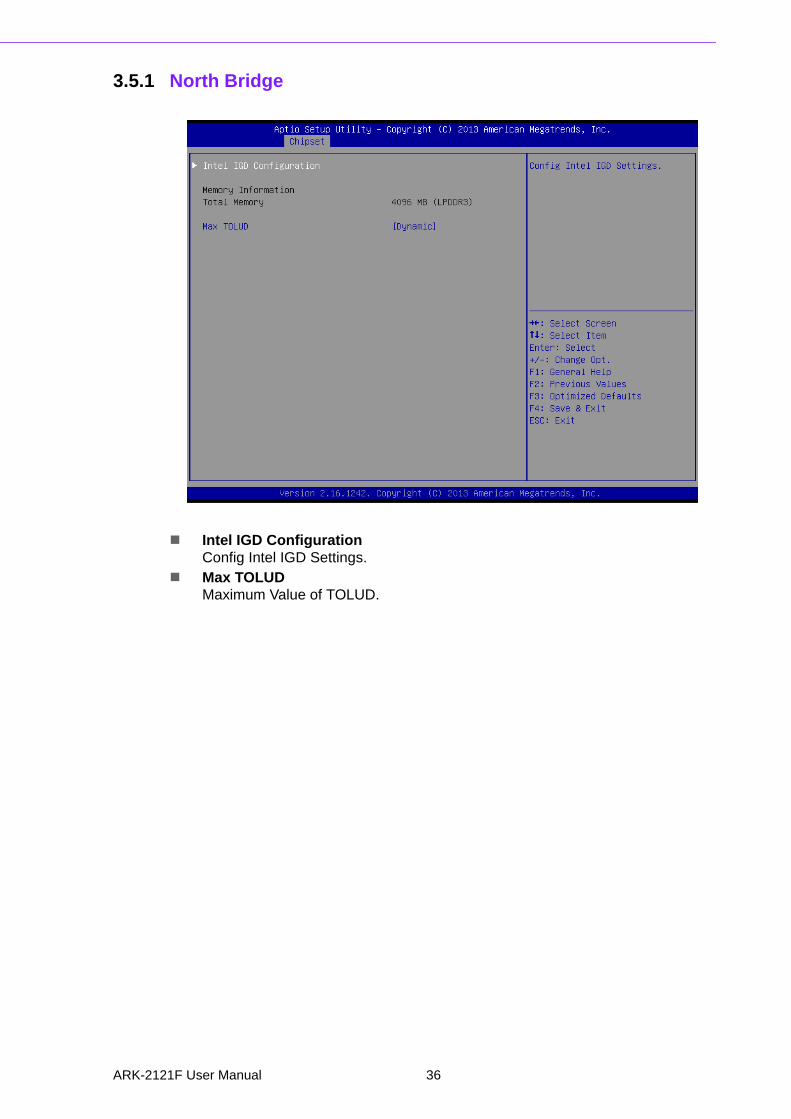
3.5.1 North Bridge
Intel IGD ConfigurationConfig Intel IGD Settings.
Max TOLUDMaximum Value of TOLUD.
ARK-2121F User Manual 36
Chapter 3
BIO
S S
ettings
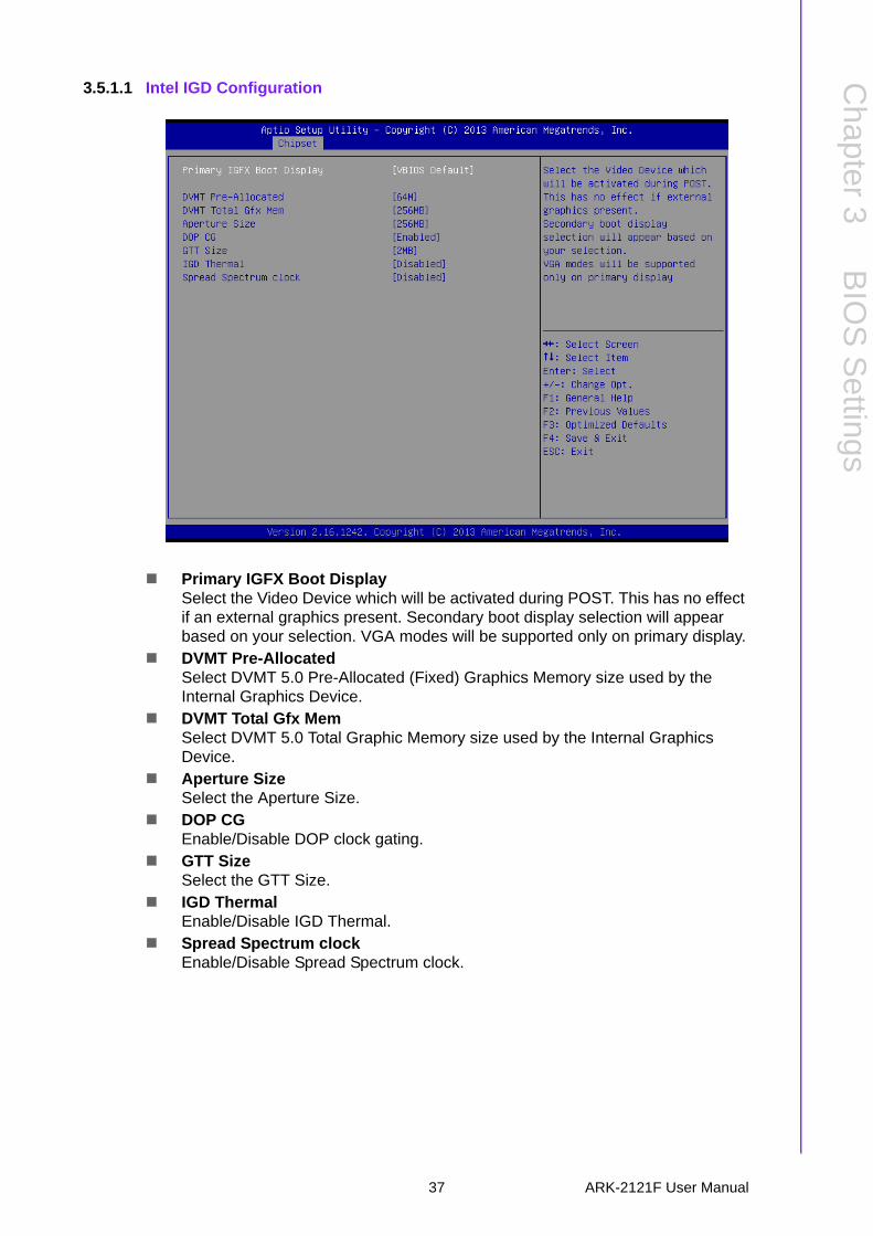
3.5.1.1 Intel IGD Configuration
Primary IGFX Boot DisplaySelect the Video Device which will be activated during POST. This has no effect if an external graphics present. Secondary boot display selection will appear based on your selection. VGA modes will be supported only on primary display.
DVMT Pre-AllocatedSelect DVMT 5.0 Pre-Allocated (Fixed) Graphics Memory size used by the Internal Graphics Device.
DVMT Total Gfx MemSelect DVMT 5.0 Total Graphic Memory size used by the Internal Graphics Device.
Aperture SizeSelect the Aperture Size.
DOP CGEnable/Disable DOP clock gating.
GTT SizeSelect the GTT Size.
IGD ThermalEnable/Disable IGD Thermal.
Spread Spectrum clockEnable/Disable Spread Spectrum clock.
37 ARK-2121F User Manual

3.5.2 South Bridge
Azalia HD AudioAzalia HD Audio Options.
USB ConfigurationUSB Configuration Settings.
PCI Express ConfigurationPCI Express Configuration settings.
High Precision TimerEnables or disables the high precision timer.
LAN1 ControllerEnable or Disable the LAN1.
LAN2 ControllerEnable or Disable the LAN2.
PCIE WakeEnable or Disable PCIE to wake the system from S5.
Restore AC Power LossSelect AC power state when power is re-applied after a power failure.
Serial IRQ ModeConfigure Serial IRQ Mode.
Global SMI LockEnable or Disable SMI lock.
BIOS Read/Write ProtectionEnable or Disable BIOS SPI region read/write protect.
ARK-2121F User Manual 38
Chapter 3
BIO
S S
ettings
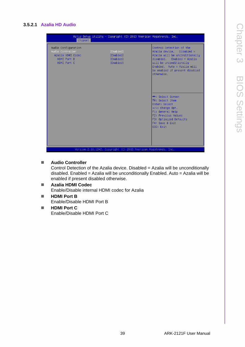
3.5.2.1 Azalia HD Audio
Audio ControllerControl Detection of the Azalia device. Disabled = Azalia will be unconditionally disabled. Enabled = Azalia will be unconditionally Enabled. Auto = Azalia will be enabled if present disabled otherwise.
Azalia HDMI CodecEnable/Disable internal HDMI codec for Azalia
HDMI Port BEnable/Disable HDMI Port B
HDMI Port CEnable/Disable HDMI Port C
39 ARK-2121F User Manual
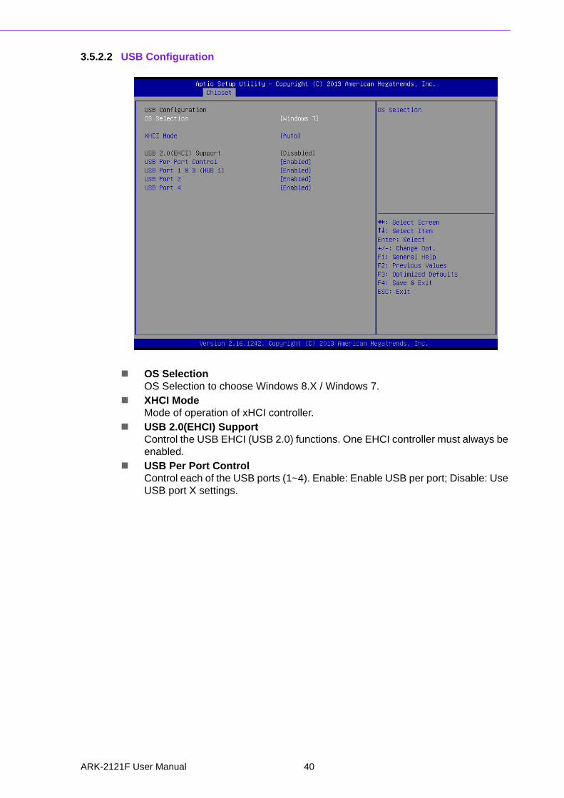
3.5.2.2 USB Configuration
OS SelectionOS Selection to choose Windows 8.X / Windows 7.
XHCI ModeMode of operation of xHCI controller.
USB 2.0(EHCI) SupportControl the USB EHCI (USB 2.0) functions. One EHCI controller must always be enabled.
USB Per Port ControlControl each of the USB ports (1~4). Enable: Enable USB per port; Disable: Use USB port X settings.
ARK-2121F User Manual 40
Chapter 3
BIO
S S
ettings
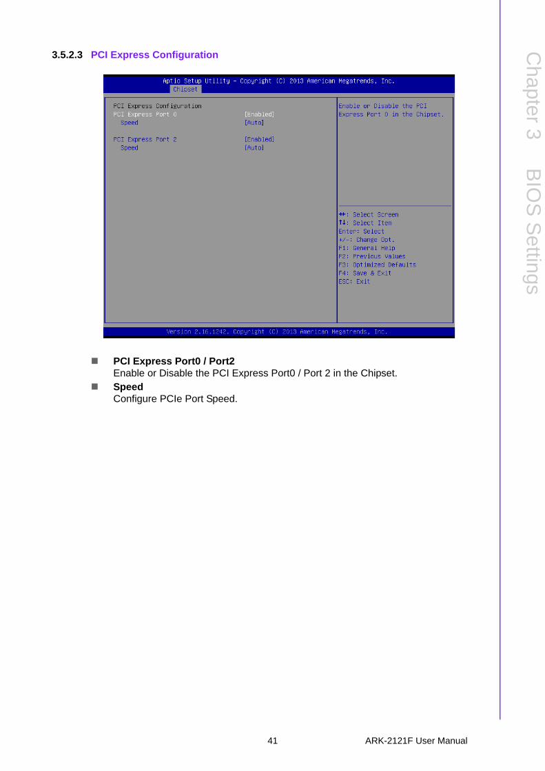
3.5.2.3 PCI Express Configuration
PCI Express Port0 / Port2Enable or Disable the PCI Express Port0 / Port 2 in the Chipset.
SpeedConfigure PCIe Port Speed.
41 ARK-2121F User Manual
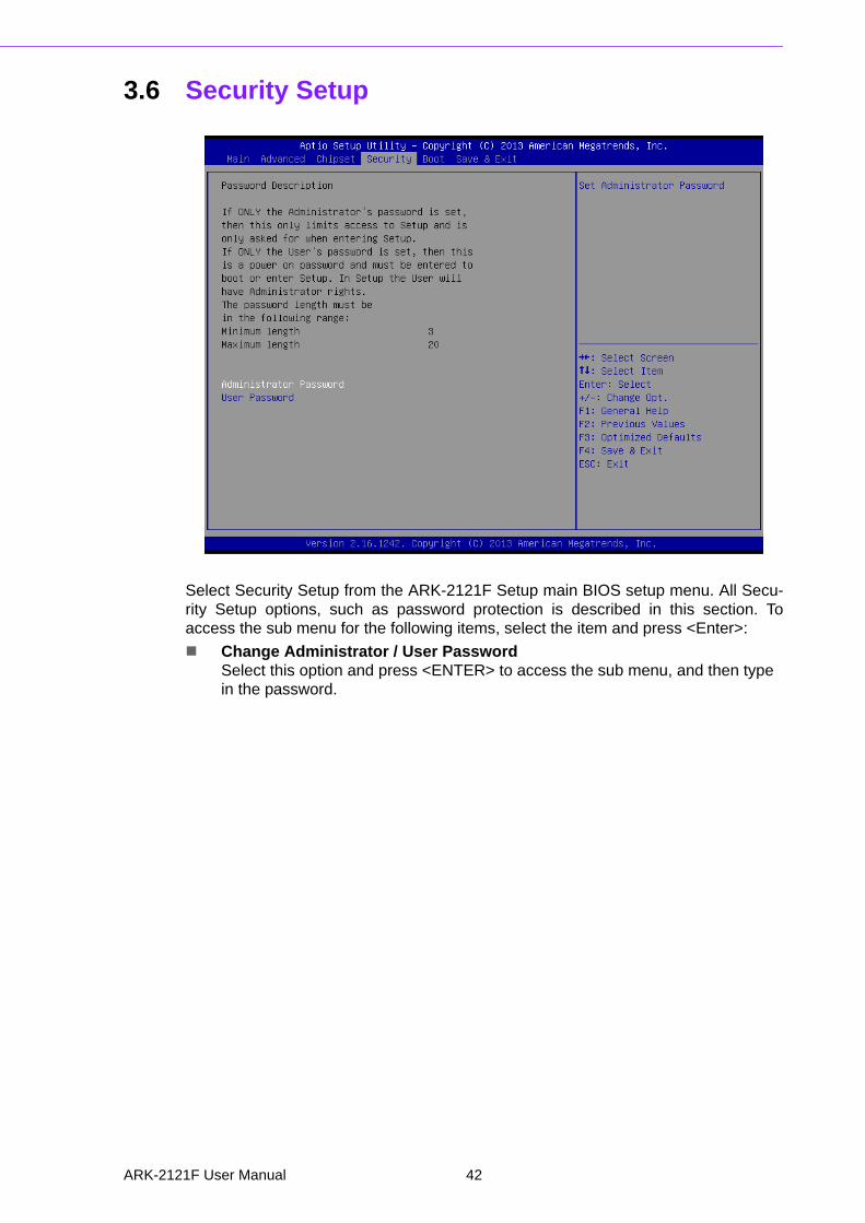
3.6 Security Setup
Select Security Setup from the ARK-2121F Setup main BIOS setup menu. All Secu-rity Setup options, such as password protection is described in this section. Toaccess the sub menu for the following items, select the item and press <Enter>:
Change Administrator / User PasswordSelect this option and press <ENTER> to access the sub menu, and then type in the password.
ARK-2121F User Manual 42
Chapter 3
BIO
S S
ettings
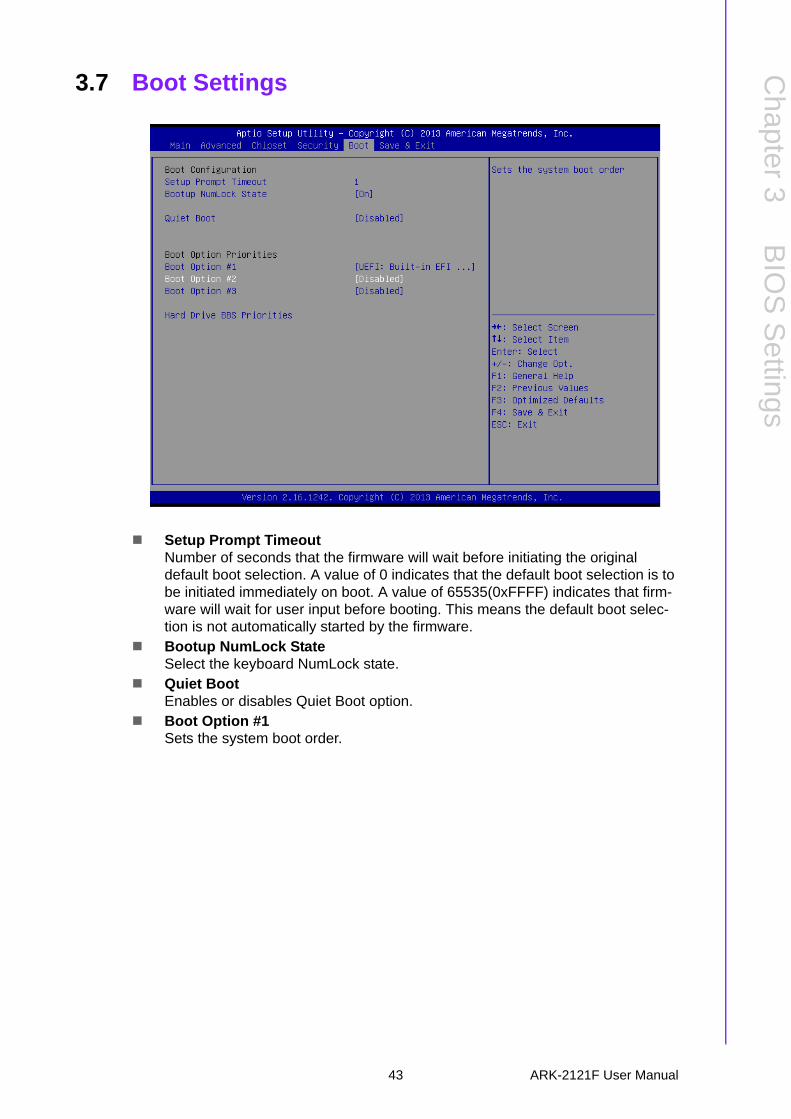
3.7 Boot Settings
Setup Prompt TimeoutNumber of seconds that the firmware will wait before initiating the original default boot selection. A value of 0 indicates that the default boot selection is to be initiated immediately on boot. A value of 65535(0xFFFF) indicates that firm-ware will wait for user input before booting. This means the default boot selec-tion is not automatically started by the firmware.
Bootup NumLock StateSelect the keyboard NumLock state.
Quiet BootEnables or disables Quiet Boot option.
Boot Option #1Sets the system boot order.
43 ARK-2121F User Manual
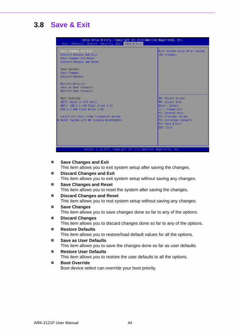
3.8 Save & Exit
Save Changes and ExitThis item allows you to exit system setup after saving the changes.
Discard Changes and ExitThis item allows you to exit system setup without saving any changes.
Save Changes and ResetThis item allows you to reset the system after saving the changes.
Discard Changes and ResetThis item allows you to rest system setup without saving any changes.
Save ChangesThis item allows you to save changes done so far to any of the options.
Discard ChangesThis item allows you to discard changes done so far to any of the options.
Restore DefaultsThis item allows you to restore/load default values for all the options.
Save as User DefaultsThis item allows you to save the changes done so far as user defaults.
Restore User DefaultsThis item allows you to restore the user defaults to all the options.
Boot OverrideBoot device select can override your boot priority.
ARK-2121F User Manual 44

Appendix A
A Watchdog Timer Sample Code
A.1 EC Watchdog Timer sample codeEC_Command_Port = 0x29AhEC_Data_Port = 0x299hWrite EC HW ram = 0x89Watch dog event flag = 0x57Watchdog reset delay time = 0x5EReset event = 0x04 Start WDT function = 0x28 ====================================================.model small.486p.stack 256.data.codeorg 100h.STARTup
mov dx, EC_Command_Portmov al,89h ; Write EC HW ram.out dx,al
mov dx, EC_Command_Portmov al, 5Fh ; Watchdog reset delay time low byte (5Eh is high byte) index.out dx,al
mov dx, EC_Data_Portmov al, 30h ;Set 3 seconds delay time.out dx,al
mov dx, EC_Command_Portmov al,89h ; Write EC HW ram.out dx,al
mov dx, EC_Command_Portmov al, 57h ; Watch dog event flag.out dx,al
mov dx, EC_Data_Portmov al, 04h ; Reset event.out dx,al
mov dx, EC_Command_Portmov al,28h ; start WDT function.out dx,al
.exitEND
ARK-2121F User Manual 46

Appendix A
Watchdog
Tim
erS
ample
Code
47 ARK-2121F User Manual

www.advantech.comPlease verify specifications before quoting. This guide is intended for referencepurposes only.All product specifications are subject to change without notice.No part of this publication may be reproduced in any form or by any means,electronic, photocopying, recording or otherwise, without prior written permis-sion of the publisher.All brand and product names are trademarks or registered trademarks of theirrespective companies.© Advantech Co., Ltd. 2015