User Manual - apc.com · NetShelter SV User Manual 1 General Information Introduction The...
34
User Manual Racks and Accessories NetShelter SV AR2200, AR2201, AR2280, AR2400, AR2400FP1, AR2401, AR2407, AR2480, AR2487, AR2500, AR2501, AR2507, AR2580, AR2587 990-4823A-001 Publication Date: 2013
Transcript of User Manual - apc.com · NetShelter SV User Manual 1 General Information Introduction The...
User ManualRacks and AccessoriesNetShelter SV
AR2200, AR2201, AR2280, AR2400, AR2400FP1, AR2401, AR2407, AR2480, AR2487, AR2500, AR2501, AR2507, AR2580, AR2587
990-4823A-001
Publication Date: 2013

This manual is available in English on the APC Web site (www.apc.com).Dieses Handbuch ist in Deutsch auf der APC Webseite (www.apc.com) verfügbar.
Este manual está disponible en español en la página web de APC (www.apc.com).
Ce manuel est disponible en français sur le site internet d’APC (www.apc.com).
Questo manuale è disponibile in italiano sul sito web di APC (www.apc.com).APC (www.apc.com)
Instrukcja obslugi w jezyku polskim jest dostepna na stronie internetowej APC (www.apc.com).
Данное руководство на русском языке доступно на сайте APC (www.apc.com)
Bu kullanim klavuzunun Türkçesi APC web sayfasinda (www.apc.com) mevcuttur.
Este manual está disponível em português no site da APC (www.apc.com).

DisclaimerThe information presented in this manual is not warranted by Schneider Electric to be authoritative, error free, or complete. This publication is not meant to be a substitute for a detailed operational and site specific development plan. Therefore, Schneider Electric assumes no liability for damages, violations of codes, improper installation, or any other problems that could arise based on the use of this publication.
The information contained in this publication is provided as is and has been prepared solely for the purpose of evaluating data center design and construction. This publication has been compiled in good faith by Schneider Electric. However, no representation is made or warranty given, either express or implied, as to the completeness or accuracy of the information this publication contains.
IN NO EVENT SHALL SCHNEIDER ELECTRIC, OR ANY AFFILIATE OR SUBSIDIARY COMPANY OF SCHNEIDER ELECTRIC OR THEIR RESPECTIVE OFFICERS, DIRECTORS, OR EMPLOYEES BE LIABLE FOR ANY DIRECT, INDIRECT, CONSEQUENTIAL, PUNITIVE, SPECIAL, OR INCIDENTAL DAMAGES (INCLUDING, WITHOUT LIMITATION, DAMAGES FOR LOSS OF BUSINESS, CONTRACT, REVENUE, DATA, INFORMATION, OR BUSINESS INTERRUPTION) RESULTING FROM, ARISING OUT OF, OR IN CONNECTION WITH THE USE OF, OR INABILITY TO USE THIS PUBLICATION OR THE CONTENT, EVEN IF SCHNEIDER ELECTRIC HAS BEEN EXPRESSLY ADVISED OF THE POSSIBILITY OF SUCH DAMAGES. SCHNEIDER ELECTRIC RESERVES THE RIGHT TO MAKE CHANGES OR UPDATES WITH RESPECT TO OR IN THE CONTENT OF THE PUBLICATION OR THE FORMAT THEREOF AT ANY TIME WITHOUT NOTICE.
Copyright, intellectual, and all other proprietary rights in the content (including but not limited to software, audio, video, text, and photographs) rests with Schneider Electric or its licensors. All rights in the content not expressly granted herein are reserved. No rights of any kind are licensed or assigned or shall otherwise pass to persons accessing this information.
This publication shall not be for resale in whole or in part.
Please Note:
Electrical equipment should be installed, operated, serviced, and maintained only by qualified personnel. A qualified person is one who has skills and knowledge related to the construction, installation, and operation of electrical equipment and has received safety training to recognize and avoid the hazards involved.
No responsibility is assumed by Schneider Electric for any consequences arising from the use of this material.


Contents
Disclaimer . . . . . . . . . . . . . . . . . . . . . . . . . . . . . . . . . . . . . . . . . . . . . . . 1Please Note: . . . . . . . . . . . . . . . . . . . . . . . . . . . . . . . . . . . . . . . . . . . . 1
General Information........................................................ 1Introduction . . . . . . . . . . . . . . . . . . . . . . . . . . . . . . . . . . . . . . . . . . . . . . 1
Safety . . . . . . . . . . . . . . . . . . . . . . . . . . . . . . . . . . . . . . . . . . . . . . . . . . . 2Important Safety Information . . . . . . . . . . . . . . . . . . . . . . . . . . . . . . . 2
Receiving and Unpacking .............................................. 3Inspection . . . . . . . . . . . . . . . . . . . . . . . . . . . . . . . . . . . . . . . . . . . . . . . 3
Please Recycle . . . . . . . . . . . . . . . . . . . . . . . . . . . . . . . . . . . . . . . . . . 3
Moving the Equipment . . . . . . . . . . . . . . . . . . . . . . . . . . . . . . . . . . . . . 3
Unpacking . . . . . . . . . . . . . . . . . . . . . . . . . . . . . . . . . . . . . . . . . . . . . . . 4
Component Identification............................................... 5Equipment Installation Hardware . . . . . . . . . . . . . . . . . . . . . . . . . . . 6Tools (provided) . . . . . . . . . . . . . . . . . . . . . . . . . . . . . . . . . . . . . . . . . 6Tools (not provided) . . . . . . . . . . . . . . . . . . . . . . . . . . . . . . . . . . . . . . 6
Cabinet Installation......................................................... 7Moving the Cabinet . . . . . . . . . . . . . . . . . . . . . . . . . . . . . . . . . . . . . . . . 7
Level the Cabinet . . . . . . . . . . . . . . . . . . . . . . . . . . . . . . . . . . . . . . . . . 7
Joining Cabinets . . . . . . . . . . . . . . . . . . . . . . . . . . . . . . . . . . . . . . . . . . 8
Secure the Cabinet . . . . . . . . . . . . . . . . . . . . . . . . . . . . . . . . . . . . . . . . 9
Ground the Cabinet. . . . . . . . . . . . . . . . . . . . . . . . . . . . . . . . . . . . . . . . 9Bonding Location on the Cabinet . . . . . . . . . . . . . . . . . . . . . . . . . . 9
NetShelter SV User Manual i

Customize the Cabinet.................................................. 10Reverse the Front Door . . . . . . . . . . . . . . . . . . . . . . . . . . . . . . . . . . . 10
Side Panels . . . . . . . . . . . . . . . . . . . . . . . . . . . . . . . . . . . . . . . . . . . . . 12Remove and install side panels . . . . . . . . . . . . . . . . . . . . . . . . . . . . 12
Rear Doors . . . . . . . . . . . . . . . . . . . . . . . . . . . . . . . . . . . . . . . . . . . . . 12Removal. . . . . . . . . . . . . . . . . . . . . . . . . . . . . . . . . . . . . . . . . . . . . . . . 12Installation. . . . . . . . . . . . . . . . . . . . . . . . . . . . . . . . . . . . . . . . . . . . . . 13
Equipment Installation.................................................. 14Adjust Vertical Mounting Flanges. . . . . . . . . . . . . . . . . . . . . . . . . . . 14
Installation. . . . . . . . . . . . . . . . . . . . . . . . . . . . . . . . . . . . . . . . . . . . . . 15
Installing Equipment . . . . . . . . . . . . . . . . . . . . . . . . . . . . . . . . . . . . . 17
Vertical Mounting Flange Cutouts . . . . . . . . . . . . . . . . . . . . . . . . . . 17
Cable Management........................................................ 18Adjust Vertical 0 U Accessory Mounting Brackets . . . . . . . . . . . . . 18
Specifications ................................................................ 1942 U Cabinets . . . . . . . . . . . . . . . . . . . . . . . . . . . . . . . . . . . . . . . . . . . 19
42 U Cabinets, continued. . . . . . . . . . . . . . . . . . . . . . . . . . . . . . . . . . 2042 U Cabinets, continued. . . . . . . . . . . . . . . . . . . . . . . . . . . . . . . . . . 21
48 U Cabinets . . . . . . . . . . . . . . . . . . . . . . . . . . . . . . . . . . . . . . . . . . . 2248 U Cabinets, continued . . . . . . . . . . . . . . . . . . . . . . . . . . . . . . . . . 23
Limited Factory Warranty ............................................. 24Terms of Warranty . . . . . . . . . . . . . . . . . . . . . . . . . . . . . . . . . . . . . . . 24Non-transferable Warranty . . . . . . . . . . . . . . . . . . . . . . . . . . . . . . . . 24Exclusions . . . . . . . . . . . . . . . . . . . . . . . . . . . . . . . . . . . . . . . . . . . . . 24Warranty Claims . . . . . . . . . . . . . . . . . . . . . . . . . . . . . . . . . . . . . . . . . 25
NetShelter SV User Manual ii

General Information
IntroductionThe NetShelter® SVcabinet is for storage of industry-standard (EIA/ECA-310), 19-inch rack-mount hardware, which includes servers and voice, data, networking, internetworking, and Schneider Electric power protection equipment. This manual provides installation and customization instructions for the following:
• NetShelter SV 42 U, 600 mm (23.6 in.) wide, 1000 mm (39.4 in.) deep cabinet (AR2200)• NetShelter SV 42 U, 600 mm (23.6 in.) wide, 1000 mm (39.4 in.) deep cabinet without side panels
(AR2201)• NetShelter SV 42 U, 600 mm (23.6 in.) wide, 1060 mm (41.7 in.) deep cabinet (AR2400)• NetShelter SV 42 U, 600 mm (23.6 in.) wide, 1060 mm (41.7 in.) deep cabinet without
side panels (AR2401)• NetShelter SV 42 U, 600 mm (23.6 in.) wide, 1200 mm (47.2 in.) deep cabinet (AR2500)• NetShelter SV 42 U, 600 mm (23.6 in.) wide, 1200 mm (47.2 in.) deep cabinet without side panels
(AR2501)• NetShelter SV 42 U, 800 mm (31.5 in.) wide, 1000 mm (39.4 in.) deep cabinet (AR2280)• NetShelter SV 42 U, 800 mm (31.5 in.) wide, 1060 mm (41.7 in.) deep cabinet (AR2480)• NetShelter SV 42 U, 800 mm (31.5 in.) wide, 1200 mm (47.2 in.) deep cabinet (AR2580)• NetShelter SV 48 U, 600 mm (23.6 in.) wide, 1060 mm (41.7 in.) deep cabinet (AR2407)• NetShelter SV 48 U, 600 mm (23.6 in.) wide, 1200 mm (47.2 in.) deep cabinet (AR2507)• NetShelter SV 48 U, 800 mm (31.5 in.) wide, 1060 mm (41.7 in.) deep cabinet (AR2487)• NetShelter SV 48 U, 800 mm (31.5 in.) wide, 1200 mm (47.2 in.) deep cabinet (AR2587)
NOTICE• NetShelter SV cabinets are intended for use with approved equipment. If you install
other than approved equipment, fully evaluate the safety of your configuration.• Use qualified personnel to install the cabinet.
1NetShelter SV User Manual

SafetyImportant Safety Information
Read the instructions carefully to become familiar with the equipment before trying to assemble, operate, service or maintain it. The following special messages may appear throughout this manual or on the equipment to warn of potential hazards or to call attention to information that clarifies or simplifies a procedure.
The addition of this symbol to a Danger or Warning safety label indicates that an electrical hazard exists which will result in personal injury if the instructions are not followed.
This is the safety alert symbol. It is used to alert you to potential personal injury hazards. Obey all safety messages that follow this symbol to avoid possible injury or death.
DANGERIndicates an imminently hazardous situation which, if not avoided, will result in death or serious injury.
WARNINGIndicates a potentially hazardous situation which, if not avoided, can result in death or serious injury.
CAUTIONIndicates a potentially hazardous situation which, if not avoided, can result in moderate injury.
NOTICEAddresses practices not related to physical injury including certain environmental hazards, potential damage or loss of data.
NetShelter SV User Manual2

Receiving and Unpacking
InspectionUpon receipt, inspect the package and contents for damage. Verify the contents are complete.
Report missing contents, damage, or other problems immediately to Schneider Electric or your Schneider Electric reseller. Keep all packaging for inspection if damage is found.
Please Recycle
The shipping materials are recyclable. Save them for later use, or dispose of them appropriately.
Moving the EquipmentRecommended tools for moving the equipment while it is still on the pallet:
NOTICESchneider Electric is not responsible for damage sustained during shipment of this product.
Overview Introduction
Tools
Safety and handling
Pallet Jack Forklift
3NetShelter SV User Manual
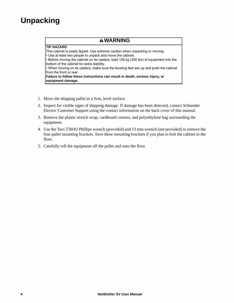
Unpacking
1. Move the shipping pallet to a firm, level surface. 2. Inspect for visible signs of shipping damage. If damage has been detected, contact Schneider
Electric Customer Support using the contact information on the back cover of this manual.3. Remove the plastic stretch wrap, cardboard corners, and polyethylene bag surrounding the
equipment.4. Use the Torx T30/#2 Phillips wrench (provided) and 13 mm wrench (not provided) to remove the
four pallet mounting brackets. Save these mounting brackets if you plan to bolt the cabinet to the floor.
5. Carefully roll the equipment off the pallet and onto the floor.
WARNINGTIP HAZARDThis cabinet is easily tipped. Use extreme caution when unpacking or moving. • Use at least two people to unpack and move the cabinet.• Before moving the cabinet on its casters, load 158 kg (350 lbs) of equipment into the bottom of the cabinet for extra stability.• When moving on its casters, make sure the leveling feet are up and push the cabinet from the front or rear.Failure to follow these instructions can result in death, serious injury, or equipment damage.
NetShelter SV User Manual4

Component Identification
Item Description Qty Item Description Qty
Roof 1 Leveling Feet 4 Rear Frame 1 Casters 4 Grounding wire 3 Front Frame 1 Rear Split Doors 2 Vertical Mounting Flanges 4 Side Panels 2 Door and Side Panel Keys 2 Horizontal Side Braces 6 Door Handles 2 Accessory Mounting Brackets 4 Front Door 1 Base 1 Roof/Base Access Panels 2
ns2118a
5NetShelter SV User Manual
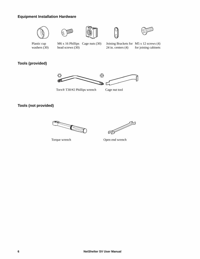
Equipment Installation Hardware
Tools (provided)
Tools (not provided)
Plastic cup washers (30)
M6 x 16 Phillips head screws (30)
Cage nuts (30) Joining Brackets for 24 in. centers (4)
M5 x 12 screws (4)for joining cabinets
Torx® T30/#2 Phillips wrench Cage nut tool
Torque wrench Open end wrench
NetShelter SV User Manual6

Cabinet Installation
Moving the Cabinet
Level the Cabinet 1. Using a 13 mm wrench, lower each
leveling foot until in makes contact with the floor.
2. Adjust each foot until the equipment is level and plumb.
WARNINGTIP HAZARDThis cabinet is easily tipped. Use extreme caution when unpacking or moving.• Use at least two people to unpack and move the cabinet.• Before moving the cabinet on its casters, load 158 kg (350 lb) of equipment into the bottom equipment mounting space of the cabinet for extra stability.• When moving on its casters, make sure the leveling feet are up and push the cabinet from the front or rear.Failure to follow these instructions can result in death, serious injury, or equipment damage.
NOTICEThe leveling feet provide a stable base if the floor is uneven, but cannot compensate for a steeply sloped surface.
ns2130a
20 UMAX:
(1,014 lb)460 kg
MAX:
ns20
04a
7NetShelter SV User Manual

Joining CabinetsCabinets can be joined with or without side panels installed to provide for alignment and some stability. The cabinets are shipped with pre-installed joining brackets for 600 mm centers. To join on 24 in. centers, the cabinet is provided with 24 in. joining brackets in the hardware bag.
1. Remove the front and rear doors.2. The cabinet is preinstalled with 600 mm centers. To join with 24 in. centers, replace the
preinstalled joining brackets with 24 in. joining brackets (provided in the hardware bag).3. Align the cabinets and join them using one M5 x 12 flat-head screw (provided in the hardware
bag) per bracket—two brackets for the front and two brackets for the rear.4. Reinstall the doors.
WARNINGTIP HAZARDJoining cabinets provides limited stability. Ensure the cabinet is secured to the floor before installing equipment.Failure to follow these instructions can result in serious injury or equipment damage.
ns2005a
600 mm
x 4
NetShelter SV User Manual8

Secure the Cabinet
To secure the cabinet to the floor, use fastener locations on the outside or inside of the cabinet and the bolt-down brackets (provided).
Ground the CabinetEach cabinet should be bonded directly to a common ground using the designated grounding location (two M6 threaded inserts) at the bottom rear of the cabinet.
• Use a Common Bonding Network Jumper kit (not provided). For example, Listed [KDER] Panduit® RGCBNJ660PY or equivalent.
• Use paint-piercing washers between ground terminal and cabinet frame or remove paint on frame under ground terminals per NEC NFPA 70 Article 250.12
• Torque screws to (60 in-lb, 6.8 N-m).
Bonding Location on the Cabinet
NOTICEBolt-down brackets secure the cabinet to the pallet during shipment. Remove them from the cabinet and pallet and save them to secure the cabinet to the floor during installation.
WARNINGTIP HAZARDSecure the cabinet to the floor before installing equipment.Failure to follow these instructions can result in serious injury or equipment damage.
ns20
11a
ns2012a
9NetShelter SV User Manual

Customize the Cabinet
Reverse the Front Door You can reverse the front door so that the door is hinged on the opposite side.
1. Remove the handle using the Torx T30/#2 Phillips wrench (provided).
2. Unfasten the ground wire from the cabinet and door, then remove the door.
3. Rotate and reinstall the door to the opposite side. Remove any plastic hole plugs and reinstall the ground wire to the door and cabinet.
ns2006a
ns2007a
ns2008a
NetShelter SV User Manual10

4. Remove and reinstall the latch and washer oriented as shown using a Torx T30/#2 Phillips wrench. The washer is rotated 90 degrees from its original orientation, and the latch is rotated 180 degrees.
5. Reinstall the handle to the door. Torque the screws to 28 - 30 in-lb (3.2 - 3.4 N-m).
ns17
66b
ns20
09a
11NetShelter SV User Manual
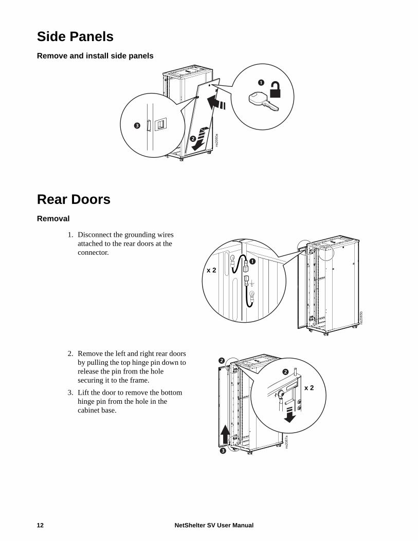
Side Panels Remove and install side panels
Rear DoorsRemoval
1. Disconnect the grounding wires attached to the rear doors at the connector.
2. Remove the left and right rear doors by pulling the top hinge pin down to release the pin from the hole securing it to the frame.
3. Lift the door to remove the bottom hinge pin from the hole in the cabinet base.
ns2060a
ns2065b
x 2
ns2087a
x 2
NetShelter SV User Manual12
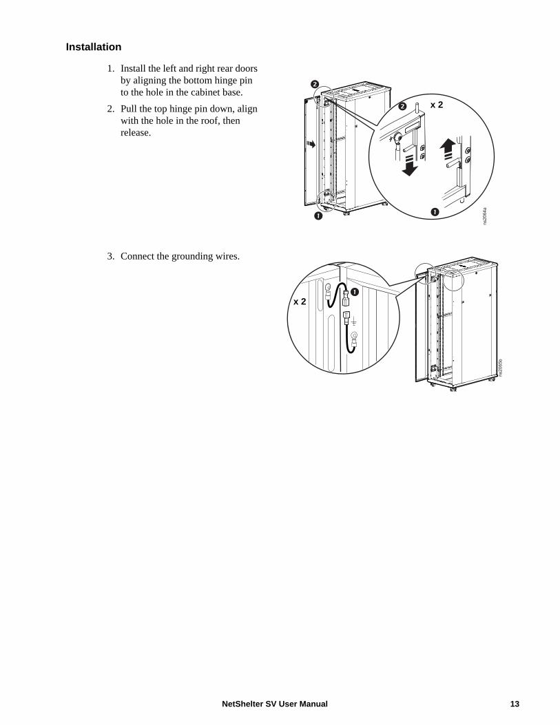
Installation
1. Install the left and right rear doors by aligning the bottom hinge pin to the hole in the cabinet base.
2. Pull the top hinge pin down, align with the hole in the roof, then release.
3. Connect the grounding wires.
ns2064a
x 2
ns2065b
x 2
13NetShelter SV User Manual

Equipment Installation
Adjust Vertical Mounting FlangesVertical mounting flanges come factory-installed in the proper location for use with rack-mountable equipment. The mounting flanges are adjustable towards the front or the rear of the cabinet to fit different rails or equipment with other depths to accommodate a wide variety of networking and telecommunications equipment.
Adjustable Vertical Mounting Flange
NOTICENetShelter SV cabinets are intended for use with Listed equipment. If you install un-Listed equipment, you should evaluate the safety of your configuration.
Cabinet Depth Factory Installed Minimum Depth Maximum Depth1000 mm 678 mm (26.7 in.) 168 mm (6.6 in.) 718 mm (28.3 in.)1060 mm 738 mm (29.1 in.) 168 mm (6.6 in.) 778 mm (30.6 in.)1200 mm 738 mm (29.1 in.) 258 mm (10.2 in.) 918 mm (36.1 in.)
NOTICEIf the vertical mounting flanges are adjusted from their factory mounting position more than 60 mm (2.4 in.), the vertical mounting flanges attach to the cabinet side brace using cage nuts and fasteners. Refer to the instructions on page 15.
ns2013a
NetShelter SV User Manual14

Installation
1. Use the Torx T30/#2 Phillips wrench (provided) to adjust a vertical mounting flange. Remove the T30 screws at the top, middle, and bottom of the vertical mounting flange. Save the screws for adjustment and reinstallation in the new position.
CAUTIONSTABILITY HAZARDWhen adjusting vertical mounting flanges, ensure that no equipment is installed on the vertical mounting flanges.Failure to follow these instructions can result in injury or equipment damage.
NOTICE• Vertical mounting flange attachment positions are in 10 mm (0.4 in.) increments.• If the vertical mounting flanges are adjusted from their factory mounting position more than 60 mm (2.4 in.), the vertical mounting flanges attach to the cabinet side brace using cage nuts and fasteners.
ns2014a
600 mm cabinet 800 mm cabinet
ns2030a
15NetShelter SV User Manual
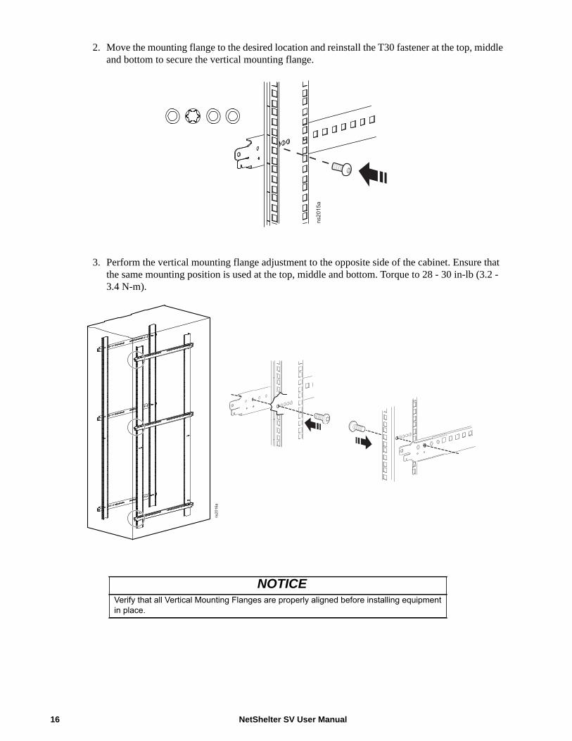
2. Move the mounting flange to the desired location and reinstall the T30 fastener at the top, middle and bottom to secure the vertical mounting flange.
3. Perform the vertical mounting flange adjustment to the opposite side of the cabinet. Ensure that the same mounting position is used at the top, middle and bottom. Torque to 28 - 30 in-lb (3.2 - 3.4 N-m).
NOTICEVerify that all Vertical Mounting Flanges are properly aligned before installing equipment in place.
ns2015a
ns2016a
NetShelter SV User Manual16
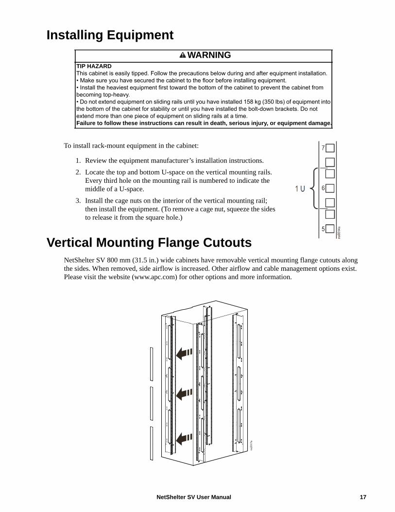
Installing Equipment
To install rack-mount equipment in the cabinet:
1. Review the equipment manufacturer’s installation instructions.2. Locate the top and bottom U-space on the vertical mounting rails.
Every third hole on the mounting rail is numbered to indicate the middle of a U-space.
3. Install the cage nuts on the interior of the vertical mounting rail; then install the equipment. (To remove a cage nut, squeeze the sides to release it from the square hole.)
Vertical Mounting Flange CutoutsNetShelter SV 800 mm (31.5 in.) wide cabinets have removable vertical mounting flange cutouts along the sides. When removed, side airflow is increased. Other airflow and cable management options exist. Please visit the website (www.apc.com) for other options and more information.
WARNINGTIP HAZARDThis cabinet is easily tipped. Follow the precautions below during and after equipment installation.• Make sure you have secured the cabinet to the floor before installing equipment.• Install the heaviest equipment first toward the bottom of the cabinet to prevent the cabinet from becoming top-heavy.• Do not extend equipment on sliding rails until you have installed 158 kg (350 lbs) of equipment into the bottom of the cabinet for stability or until you have installed the bolt-down brackets. Do not extend more than one piece of equipment on sliding rails at a time.Failure to follow these instructions can result in death, serious injury, or equipment damage.
ns2017a
17NetShelter SV User Manual

Cable ManagementRoute, secure, and organize cables using the multiple cable access openings on the cabinet roof, sides, and bottom, the accessory mounting brackets included with the cabinet, plus the variety of cable management accessories available.
Adjust Vertical 0 U Accessory Mounting BracketsThe vertical 0 U accessory mounting brackets (four included) provide toolless mounting capabilities for Schneider Electric Rack Power Distribution Units (PDUs) and cable management. They also provide tie-off locations for cables.
The factory-default position for the vertical 0 U accessory brackets is in the rear of the cabinet. The brackets are positioned for full-height vertical Rack PDUs.The bracket can be moved up or down to accommodate different accessories. Additional brackets are available for purchase as requirements change.
1. Use the Torx® T30/#2 Phillips wrench (provided) to remove the two T30 screws.2. Move to the desired position, and reinstall the brackets.
ns2018a
NetShelter SV User Manual18

Specifications
42 U Cabinets
AR2200 AR2400 AR2401
Height 2057 mm (81.0 in.) 2057 mm (81.0 in.) 2057 mm (81.0 in.)
Width 600 mm (23.6 in.) 600 mm (23.6 in.) 600 mm (23.6 in.)
Depth 1000 mm (39.4 in.) 1060 mm (41.7 in.) 1060 mm (41.7 in.)
Net weight 108.8 kg (239.9 lb) 112.2 kg (247.4 lb) 85.0 kg (187.4 lb)
Total open area front door 778 176 mm2 (1,206 in2)
778 176 mm2 (1,206 in2)
778 176 mm2 (1,206 in2)
Total open area rear door 805 637 mm2 (1,249 in2)
805 637 mm2 (1,249 in2)
805 637 mm2 (1,249 in2)
Open area per U front door 18 528 mm2 (28.7 in2) 18 528 mm2 (28.7 in2) 18 528 mm2 (28.7 in2)
Open area per U rear door 19 182 mm2 (29.7 in2) 19 182 mm2 (29.7 in2) 19 182 mm2 (29.7 in2)
Perforation pattern 69.4 % open area 69.4 % open area 69.4 % open area
Perforation pattern front door 69.3 % 69.3 % 69.3 %
Perforation pattern rear door 71.7 % 71.7 % 71.7 %
Clearance (for wiring between front door and vertical mounting flange)
14.0 mm (0.6 in.) 14.0 mm (0.6 in.) 14.0 mm (0.6 in.)
Weight rating: static (leveling feet) load
1000 kg (2,205 lb) 1000 kg (2,205 lb) 1000 kg (2,205 lb)
Weight rating: dynamic (casters) load†
460 kg (1,014 lb) 460 kg (1,014 lb) 460 kg (1,014 lb)
Weight rating: cabinet roof cable load
45 kg (99 lb) 45 kg (99 lb) 45 kg (99 lb)
† To move the cabinet on its casters, the equipment load must be evenly distributed, must not exceed 460 kg (1,014 lb)and the equipment must not be installed above the 20 U height.
19NetShelter SV User Manual

42 U Cabinets, continued
AR2500 AR2280
Height 2057 mm (81.0 in.) 2057 mm (81.0 in.)
Width 600 mm (23.6 in.) 800 mm (31.5 in.)
Depth 1200 mm (47.2 in.) 1000 mm (39.4 in.)
Net weight 121.3 kg (267.4 lb) 126.7 kg (279.3 lb)
Total open area front door 778 176 mm2 (1,206 in2) 1 137 330 mm2 (1,763 in2)
Total open area rear door 805 637 mm2 (1,2492) 1 171 657 mm2 (1,816 in2)
Open area per U front door 18 528 mm2 (28.7 in2) 27 079 mm2 (42.0 in2)
Open area per U rear door 19 182 mm2 (29.7 in2) 27 897 mm2 (43.2 in2)
Perforation pattern 69.4% open area 69.4% open area
Perforation pattern front door 69.3% 75.8%
Perforation pattern rear door 71.7% 78.0%
Clearance (for wiring between front door and vertical mounting flange)
14.0 mm (0.6 in.) 14.0 mm (0.6 in.)
Weight rating: static (leveling feet) load 1000 kg (2,205 lb) 1000 kg (2,205 lb)
Weight rating: dynamic (casters) load† 460 kg (1,014 lb) 460 kg (1,014 lb)
Weight rating: cabinet roof cable load 45 kg (99 lb) 45 kg (99 lb)† To move the cabinet on its casters, the equipment load must be evenly distributed, and must not exceed 460 kg (1,014 lb)
and equipment must not be installed above the 20 U height.
NetShelter SV User Manual20

42 U Cabinets, continued
AR2480 AR2580
Height 2057 mm (81.0 in.) 2057 mm (81.0 in.)
Width 800 mm (31.5 in.) 800 mm (31.5 in.)
Depth 1060 mm (41.7 in.) 1200 mm (47.2 in.)
Net weight 130.5 kg (287.7 lb) 139.5 kg (307.5 lb)
Total open area front door 1 137 330 mm2 (1,763 in2) 1 137 330 mm2 (1,763 in2)
Total open area rear door 1 171 657 mm2 (1,816 in2) 1 171 657 mm2 (1,816 in2)
Open area per U front door 27 079 mm2 (42.0 in2) 27 079 mm2 (42.0 in2)
Open area per U rear door 27 897 mm2 (43.2 in2) 27 897 mm2 (43.2 in2)
Perforation pattern 69.4% open area 69.4% open area
Perforation pattern front door 75.8% 75.8%
Perforation pattern rear door 78.0% 78.0%
Clearance (for wiring between front door and vertical mounting flange)
14.0 mm (0.6 in.) 14.0 mm (0.6 in.)
Weight rating: static (leveling feet) load 1000 kg (2,205 lb) 1000 kg (2,205 lb)
Weight rating: dynamic (casters) load† 460 kg (1,014 lb) 460 kg (1,014 lb)
Weight rating: cabinet roof cable load 45 kg (99 lb) 45 kg (99 lb)
† To move the cabinet on its casters, the equipment load must be evenly distributed, and must not exceed 460 kg (1,014 lb)and equipment must not be installed above the 20 U height.
21NetShelter SV User Manual
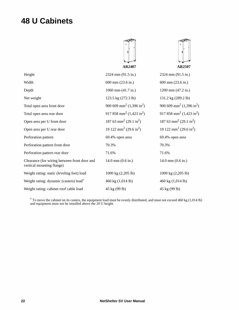
48 U Cabinets
AR2407 AR2507
Height 2324 mm (91.5 in.) 2324 mm (91.5 in.)
Width 600 mm (23.6 in.) 600 mm (23.6 in.)
Depth 1060 mm (41.7 in.) 1200 mm (47.2 in.)
Net weight 123.5 kg (272.3 lb) 131.2 kg (289.2 lb)
Total open area front door 900 609 mm2 (1,396 in2) 900 609 mm2 (1,396 in2)
Total open area rear door 917 858 mm2 (1,423 in2) 917 858 mm2 (1,423 in2)
Open area per U front door 187 63 mm2 (29.1 in2) 187 63 mm2 (29.1 in2)
Open area per U rear door 19 122 mm2 (29.6 in2) 19 122 mm2 (29.6 in2)
Perforation pattern 69.4% open area 69.4% open area
Perforation pattern front door 70.3% 70.3%
Perforation pattern rear door 71.6% 71.6%
Clearance (for wiring between front door and vertical mounting flange)
14.0 mm (0.6 in.) 14.0 mm (0.6 in.)
Weight rating: static (leveling feet) load 1000 kg (2,205 lb) 1000 kg (2,205 lb)
Weight rating: dynamic (casters) load† 460 kg (1,014 lb) 460 kg (1,014 lb)
Weight rating: cabinet roof cable load 45 kg (99 lb) 45 kg (99 lb)
† To move the cabinet on its casters, the equipment load must be evenly distributed, and must not exceed 460 kg (1,014 lb)and equipment must not be installed above the 20 U height.
NetShelter SV User Manual22
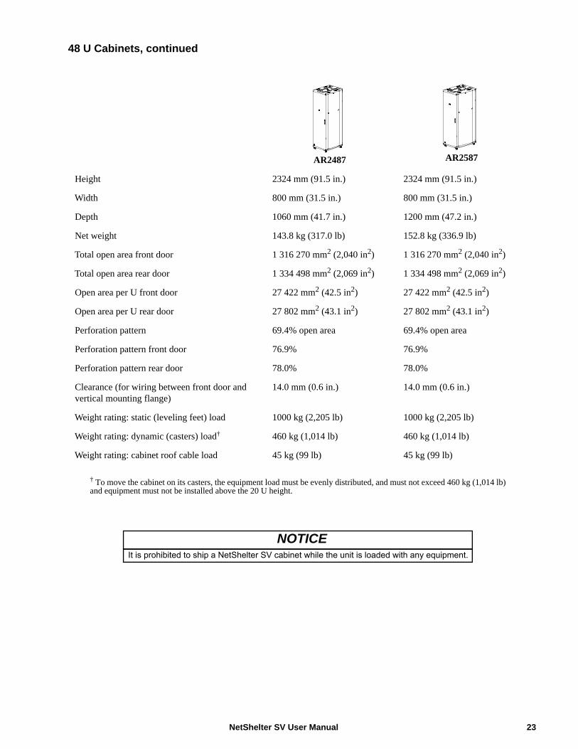
48 U Cabinets, continued
AR2487 AR2587
Height 2324 mm (91.5 in.) 2324 mm (91.5 in.)
Width 800 mm (31.5 in.) 800 mm (31.5 in.)
Depth 1060 mm (41.7 in.) 1200 mm (47.2 in.)
Net weight 143.8 kg (317.0 lb) 152.8 kg (336.9 lb)
Total open area front door 1 316 270 mm2 (2,040 in2) 1 316 270 mm2 (2,040 in2)
Total open area rear door 1 334 498 mm2 (2,069 in2) 1 334 498 mm2 (2,069 in2)
Open area per U front door 27 422 mm2 (42.5 in2) 27 422 mm2 (42.5 in2)
Open area per U rear door 27 802 mm2 (43.1 in2) 27 802 mm2 (43.1 in2)
Perforation pattern 69.4% open area 69.4% open area
Perforation pattern front door 76.9% 76.9%
Perforation pattern rear door 78.0% 78.0%
Clearance (for wiring between front door and vertical mounting flange)
14.0 mm (0.6 in.) 14.0 mm (0.6 in.)
Weight rating: static (leveling feet) load 1000 kg (2,205 lb) 1000 kg (2,205 lb)
Weight rating: dynamic (casters) load† 460 kg (1,014 lb) 460 kg (1,014 lb)
Weight rating: cabinet roof cable load 45 kg (99 lb) 45 kg (99 lb)
† To move the cabinet on its casters, the equipment load must be evenly distributed, and must not exceed 460 kg (1,014 lb)and equipment must not be installed above the 20 U height.
NOTICEIt is prohibited to ship a NetShelter SV cabinet while the unit is loaded with any equipment.
23NetShelter SV User Manual

Limited Factory Warranty
The limited warranty provided by Schneider Electric in this Statement of Limited Factory Warranty applies only to Products you purchase for your commercial or industrial use in the ordinary course of your business.
Terms of Warranty
Schneider Electric warrants its products to be free from defects in materials and workmanship for a period of five years from the date of purchase. Its obligation under this warranty is limited to repairing or replacing, at its sole discretion, any such defective products. This warranty does not apply to equipment that has been damaged by accident, negligence, or misapplication or has been altered or modified in any way. Repair or replacement of a defective product or part thereof does not extend the original warranty period. Any parts furnished under this warranty may be new or factory- remanufactured.
Non-transferable Warranty
This warranty applies only to the original purchaser who must have properly registered the product. Product may be registered at http://www.warranty.apc.com.
Exclusions
Schneider Electric shall not be liable under the warranty if its testing and examination disclose that the alleged defect in the product does not exist or was caused by end user’s or any third person’s misuse, negligence, improper installation or testing. Further, Schneider Electric shall not be liable under the warranty for unauthorized attempts to repair or modify wrong or inadequate electrical voltage or connection, inappropriate on-site operation conditions, corrosive atmosphere, repair, installation, start-up by non-Schneider Electric designated personnel, a change in location or operating use, exposure to the elements, Acts of God, fire, theft, or installation contrary to Schneider Electric recommendations or specifications or in any event if the Schneider Electric serial number has been altered, defaced, or removed, or any other cause beyond the range of the intended use.
THERE ARE NO WARRANTIES, EXPRESS OR IMPLIED, BY OPERATION OF LAW OR OTHERWISE, OF PRODUCTS SOLD, SERVICED OR FURNISHED UNDER THIS AGREEMENT OR IN CONNECTION HEREWITH. SCHNEIDER ELECTRIC DISCLAIMS ALL IMPLIED WARRANTIES OF MERCHANTABILITY, SATISFACTION AND FITNESS FOR A PARTICULAR PURPOSE. SCHNEIDER ELECTRIC EXPRESS WARRANTIES WILL NOT BE ENLARGED, DIMINISHED, OR AFFECTED BY AND NO OBLIGATION OR LIABILITY WILL ARISE OUT OF, SCHNEIDER ELECTRIC RENDERING OF TECHNICAL OR OTHER ADVICE OR SERVICE IN CONNECTION WITH THE PRODUCTS. THE FOREGOING WARRANTIES AND REMEDIES ARE EXCLUSIVE AND IN LIEU OF ALL OTHER WARRANTIES AND REMEDIES. THE WARRANTIES SET FORTH ABOVE CONSTITUTE SCHNEIDER ELECTRIC SOLE LIABILITY AND PURCHASER’S EXCLUSIVE REMEDY FOR ANY BREACH OF SUCH WARRANTIES. SCHNEIDER ELECTRIC WARRANTIES RUN ONLY TO PURCHASER AND ARE NOT EXTENDED TO ANY THIRD PARTIES.
NetShelter SV User Manual24
IN NO EVENT SHALL SCHNEIDER ELECTRIC, ITS OFFICERS, DIRECTORS, AFFILIATES OR EMPLOYEES BE LIABLE FOR ANY FORM OF INDIRECT, SPECIAL, CONSEQUENTIAL OR PUNITIVE DAMAGES, ARISING OUT OF THE USE, SERVICE OR INSTALLATION, OF THE PRODUCTS, WHETHER SUCH DAMAGES ARISE IN CONTRACT OR TORT, IRRESPECTIVE OF FAULT, NEGLIGENCE OR STRICT LIABILITY OR WHETHER SCHNEIDER ELECTRIC HAS BEEN ADVISED IN ADVANCE OF THE POSSIBLY OF SUCH DAMAGES. SPECIFICALLY, SCHNEIDER ELECTRIC IS NOT LIABLE FOR ANY COSTS, SUCH AS LOST PROFITS OR REVENUE, LOSS OF EQUIPMENT, LOSS OF USE OF EQUIPMENT, LOSS OF SOFTWARE, LOSS OF DATA, COSTS OF SUBSTITUANTS, CLAIMS BY THIRD PARTIES, OR OTHERWISE.
NO SALESMAN, EMPLOYEE OR AGENT OF SCHNEIDER ELECTRIC IS AUTHORIZED TO ADD TO OR VARY THE TERMS OF THIS WARRANTY. WARRANTY TERMS MAY BE MODIFIED, IF AT ALL, ONLY IN WRITING SIGNED BY A SCHNEIDER ELECTRIC OFFICER AND LEGAL DEPARTMENT.
Warranty Claims
Customers with warranty claims issues may access the Schneider Electric worldwide customer support network by visiting http://www.apc.com/support. Select your country from the country selection pull-down menu. Open the Support tab at the top of the web page to obtain contact information for customer support in your region.
25NetShelter SV User Manual


Worldwide Customer SupportCustomer support is available at no charge via e-mail or telephone. Contact information is available at www.apc.com/support/contact.
10/2013990-4823A-001
©2013 Schneider Electric, APC and the APC logo are owned by Schneider Electric Industries S.A.S., or its affiliated companies. All other trademarks are property of their respective owners.