User InstrUctIon ManUal self retractIng lIfelInes · user must read and follow the manufacturer’s...
40
© Copyright 2007, DB Industries, Inc. USER INSTRUCTION MANUAL SELF RETRACTING LIFELINES This manual is intended to meet the Manufacturer’s Instructions as required by ANSI Z359.1 and the Canadian Standards Association, and should be used as part of an employee training program as required by OSHA. Instructions for the following series products: Ultra-Lok Wire Rope and Synthetic Rope SRLs Aerospace Style SRLs Ultra-Lok Web Style SRLs Leading Edge SRLs Aluminum Housing Model Web Style SRLs Aluminum Housing Model Wire Rope Style SRLs (See back pages for specific model numbers.) Form: 5902101 Rev: I
Transcript of User InstrUctIon ManUal self retractIng lIfelInes · user must read and follow the manufacturer’s...

© Copyright 2007, DB Industries, Inc.
User InstrUctIon ManUal self retractIng lIfelInes
This manual is intended to meet the Manufacturer’s Instructions as required by ANSI Z359.1 and the Canadian Standards Association, and should be used as part of an employee training program as required by OSHA.
Instructions for the following series products:
Ultra-Lok Wire Rope and Synthetic Rope SRLs Aerospace Style SRLs
Ultra-Lok Web Style SRLs Leading Edge SRLs
Aluminum Housing Model Web Style SRLsAluminum Housing Model Wire Rope Style SRLs
(See back pages for specific model numbers.)
Form: 5902101Rev: I


3
Figure 1 - Ultra-Lok Models, Wire and Synthetic Rope Styles
Swivel Eye
Inspection Note Label
Warning Label
Ultra-Lok Label
ID Label
Connections Label
Wire orSynthetic Rope
Self Locking Hook
Bumper
RFID Tag

4
Figure 2 - Leading Edge SRL
Swivel Eye
InspectionNote Label
WarningLabel
Ultra-LokLabel
ConnectionsLabel
Wire Rope
Shock Absorber
Self LockingSnap Hook
RFID Tag

5
Figure 3 - Ultra-Lok Models, Web Style
WarningLabel
Impact Indicator Label
Indicator Fold
ConnectingHook
Anchorage Attachment Point (Swivel Eye)
ID Label
Connections Label
Reverse LifelineLabel
RFID Tag
6
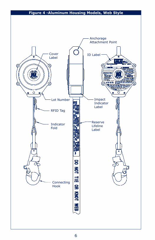
Figure 4 -Aluminum Housing Models, Web Style
CoverLabel
Anchorage Attachment Point
ID Label
Lot Number
Indicator Fold
Impact IndicatorLabel
Reserve LifelineLabel
Connecting Hook
RFID Tag

7
Figure 5 -Aluminum Housing Models, Wire Rope Style
Cover Label
Lot Number
Bumper
Self-Locking Hook
Wire Rope
ID Label
RFID Tag

8
WarnIng: This product is part of a personal fall arrest system. The user must read and follow the manufacturer’s instructions for each component of the system. These instructions must be provided to the user of this equipment. The user must read and understand these instructions before using this equipment. Manufacturer’s instructions must be followed for proper use and maintenance of this equipment. Alterations or misuse of this equipment, or failure to follow instructions, may result in serious injury or death.
IMPortant: If you have questions on the use, care, application, or suitability of this safety equipment, contact DBI‑SALA.
IMPortant: Before using this equipment, record the product identification information from the ID label in the inspection and maintenance log in section 9.0 of this manual.
DescrIPtIons
ULTRA-LOK® WIRE & SYNTHETIC ROPE STYLE SELF RETRACTING LIFELINES: Includes swivel eye anchorage, self-locking swivel snap hook with impact indicator, and choice of galvanized wire rope lifeline or stainless steel wire rope lifeline in lengths of 20, 30, 50 and 85 feet, or synthetic rope lifeline in lengths of 20, 35 and 55 feet. See Figure 1.
AEROSPACE SELF RETRACTING LIFELINES: Includes swivel eye anchorage, stainless steel self-locking swivel snap hook with impact indicator, and 30-foot stainless steel wire rope lifeline. Contains no zinc or cadmium. See Figure 1.
LEADING EDGE SELF RETRACTING LIFELINES: Includes swivel eye anchorage, self-locking swivel snap hook with impact indicator, integral shock pack, and 30-foot or 55-foot galvanized wire rope lifeline. See Figure 2.
ULTRA-LOK® WEB STYLE SELF RETRACTING LIFELINES: Includes swivel eye anchorage, self-locking snap hook, and 1-inch wide nylon web lifeline in lengths of 11 and 20 feet. See Figure 3.
ALUMINUM HOUSING WEB STYLE SELF RETRACTING LIFELINES: Includes a lightweight, heavy duty, extruded aluminum housing, self-locking snap hook, and 1-inch wide nylon web lifeline in a length of 11 feet. See Figure 4.
ALUMINUM HOUSING WIRE ROPE STYLE SELF RETRACTING LIFELINES: Includes a lightweight, heavy duty, extruded aluminum housing, self-locking swivel snap hook with impact indicator, and choice of galvanized wire rope lifeline or stainless steel wire rope lifeline in a length of 11 feet. See Figure 5.
9
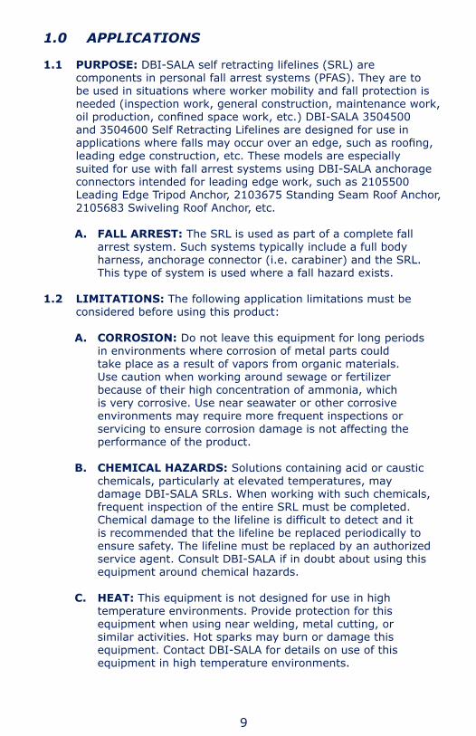
1.0 aPPlIcatIons
1.1 PURPOSE: DBI-SALA self retracting lifelines (SRL) are components in personal fall arrest systems (PFAS). They are to be used in situations where worker mobility and fall protection is needed (inspection work, general construction, maintenance work, oil production, confined space work, etc.) DBI‑SALA 3504500 and 3504600 Self Retracting Lifelines are designed for use in applications where falls may occur over an edge, such as roofing, leading edge construction, etc. These models are especially suited for use with fall arrest systems using DBI-SALA anchorage connectors intended for leading edge work, such as 2105500 Leading Edge Tripod Anchor, 2103675 Standing Seam Roof Anchor, 2105683 Swiveling Roof Anchor, etc.
A. FALL ARREST: The SRL is used as part of a complete fall arrest system. Such systems typically include a full body harness, anchorage connector (i.e. carabiner) and the SRL. This type of system is used where a fall hazard exists.
1.2 LIMITATIONS: The following application limitations must be considered before using this product:
A. CORROSION: Do not leave this equipment for long periods in environments where corrosion of metal parts could take place as a result of vapors from organic materials. Use caution when working around sewage or fertilizer because of their high concentration of ammonia, which is very corrosive. Use near seawater or other corrosive environments may require more frequent inspections or servicing to ensure corrosion damage is not affecting the performance of the product.
B. CHEMICAL HAZARDS: Solutions containing acid or caustic chemicals, particularly at elevated temperatures, may damage DBI-SALA SRLs. When working with such chemicals, frequent inspection of the entire SRL must be completed. Chemical damage to the lifeline is difficult to detect and it is recommended that the lifeline be replaced periodically to ensure safety. The lifeline must be replaced by an authorized service agent. Consult DBI-SALA if in doubt about using this equipment around chemical hazards.
C. HEAT: This equipment is not designed for use in high temperature environments. Provide protection for this equipment when using near welding, metal cutting, or similar activities. Hot sparks may burn or damage this equipment. Contact DBI-SALA for details on use of this equipment in high temperature environments.

10
note: Synthetic rope lifelines are not flame proof and must not be exposed to extreme heat. Spectra rope SRLs must not be used in environments or contact surfaces exceeding 140° F (60°C). Vectran rope SRLs must not be used in environments or contact surfaces exceeding 248° F (120°C). Technora rope SRLs must not be used in environments or contact surfaces exceeding 392° F (200°C).
D. ELECTRICAL HAZARDS: For web and synthetic rope models, there is a possibility of moisture absorption by the lifeline. Moisture absorbed by the lifeline may provide a path for electrical current to flow, resulting in electrical shock. Use caution when the lifeline may contact high voltage power lines. For wire rope models, there is a possibility of electric current flowing through the lifeline. Use caution where the lifeline may contact high voltage power lines.
E. CAPACITY: The SRL is for use by persons with a combined weight (person, clothing, tools, etc.) of 75 lbs. minimum and 310 lbs. maximum. No more than one person can connect to an SRL.
note: The 11 ft web Ultra‑Lok ‑ models 3103107 and 3103108 only ‑ have a combined weight capacity of 420 lbs.
F. LOCKING SPEED: Situations which do not allow for an unobstructed fall path should be avoided. Working in confined or cramped spaces may not allow sufficient speed to cause the SRL to lock in a fall. Working on slowly shifting materials, such as sand or grain, may not allow sufficient speed to cause the SRL to lock. A similar situation may occur on low pitched roofs, where a worker may slide instead of fall. A clear path is required to ensure positive locking of the SRL.
G. NORMAL OPERATION: Normal operation will allow the full length of the lifeline to extend and retract with no hesitation when extending and no slack when retracting as the worker moves at normal speeds. If a fall occurs, a speed sensing brake system will activate, stopping the fall and absorbing much of the energy created. For falls that occur near the end of the lifeline travel, the reserve lifeline system will ensure a reduced impact fall arrest. If a fall has been arrested, the SRL must be taken out of service and inspected. See section 5.0. Sudden or quick movements should be avoided during the normal work operation, as this may cause the SRL to lock-up.
H. TRAINING: This equipment must be installed and used by persons trained in its correct application and use.
1.3 Refer to national standards, including ANSI Z359.1, and applicable local, state, and federal (OSHA) requirements governing this

11
equipment for more information on personal fall arrest systems and associated system components.
2.0 sYsteM reQUIreMents
2.1 COMPATIBILITY OF COMPONENTS: DBI-SALA equipment is designed for use with DBI-SALA approved components and subsystems only. Substitutions or replacements made with non-approved components or subsystems may jeopardize compatibility of equipment and may effect the safety and reliability of the complete system.
2.2 COMPATIBILITY OF CONNECTORS: Connectors are considered to be compatible with connecting elements when they have been designed to work together in such a way that their sizes and shapes do not cause their gate mechanisms to inadvertently open regardless of how they become oriented. Contact DBI-SALA if you have any questions about compatibility.
Connectors (hooks, carabiners, and D-rings) must be capable of supporting at least 5,000 lbs. (22.2 kN). Connectors must be compatible with the anchorage or other system components. Do not use equipment that is not compatible. Non-compatible connectors may unintentionally disengage. See Figure 6. Connectors must be compatible in size, shape, and strength. Self locking snap hooks and carabiners are required by ANSI Z359.1 and OSHA.
Figure 6 - Unintentional Disengagement (Roll-out)If the connecting element that a snap hook (shown) or carabiner attaches to is undersized or irregular in shape, a situation could occur where the connecting element applies a force to the gate of the snap hook or carabiner. This force may cause the gate (of either a self-locking or a non-locking snap hook) to open, allowing the snap hook or carabiner to disengage from the connecting point.
1. Force is applied to the snap hook.
2. The gate presses against the connecting ring.
3. The gate opens allowing the snap hook to slip off.
Small ring or other non-compatibly shaped element

12
2.3 MAKING CONNECTIONS: Only use self-locking snap hooks and carabiners with this equipment. Only use connectors that are suitable to each application. Ensure all connections are compatible in size, shape, and strength. Do not use equipment that is not compatible. Ensure all connectors are fully closed and locked.
DBI-SALA connectors (snap hooks and carabiners) are designed to be used only as specified in each product’s user’s instructions. See Figure 7 for inappropriate connections. DBI-SALA snap hooks and carabiners should not be connected:
A. To a D-ring to which another connector is attached.
B. In a manner that would result in a load on the gate.
note: Large throat opening snap hooks should not be connected to standard size D‑rings or similar objects which will result in a load on the gate if the hook or D‑ring twists or rotates. Large throat snap hooks are designed for use on fixed structural elements such as rebar or cross members that are not shaped in a way that can capture the gate of the hook.
C. In a false engagement, where features that protrude from the snap hook or carabiner catch on the anchor and without visual confirmation seems to be fully engaged to the anchor point.
D. To each other.
E. Directly to webbing or rope lanyard or tie-back (unless the manufacturer’s instructions for both the lanyard and connector specifically allow such a connection).
Figure 7 - Inappropriate Connections

13
F. To any object which is shaped or dimensioned such that the snap hook or carabiner will not close and lock, or that roll-out could occur.
2.4 ANCHORAGE STRUCTURE: The anchorage to which the SRL is attached must be capable of sustaining static loads in the directions applied by the personal fall arrest system of at least 3,600 lbs. with certification of a qualified person, or 5,000 lbs. without certification. See ANSI Z359.1 for certification requirements. When more than one personal fall arrest system is attached to the same structure, the strength requirements stated above must be multiplied by the number of personal fall arrest systems attached to the structure.
• From OSHA 1910.66 and 1926.500: Anchorages used for attachment of a PFAS shall be independent of any anchorage being used to support or suspend platforms, and must support at least 5,000 lbs. (22.2 kN) per user attached, or be designed, installed, and used as part of a complete PFAS which maintains a safety factor of at least two, and is supervised by a qualified person.
2.5 In applications where an SRL is used in conjunction with a horizontal system (i.e. horizontal I-beams, trolleys), the SRL and horizontal system components must be compatible. Horizontal systems must be designed and installed under the supervision of a qualified engineer.
2.6 When using an SRL with a support structure (i.e. tripod, davit arm), ensure the support structure is compatible with the connection, operation, stability, and strength of the SRL.
3.0 oPeratIon anD Use
WarnIng: Do not alter or intentionally misuse this equipment. Consult with DBI‑SALA when using this equipment in combination with components or subsystems other than those described in this manual. Some subsystem and component combinations may interfere with the operation of this equipment. Use caution when using this equipment around moving machinery, electrical and chemical hazards, and sharp edges.
WarnIng: Consult your doctor if there is reason to doubt your fitness to safely absorb the shock from a fall arrest. Age and fitness seriously affect a worker’s ability to withstand falls. Pregnant women or minors must not use DBI‑SALA self retracting lifelines.
3.1 BEFORE EACH USE of this equipment, carefully inspect it according to steps listed in section 5.0.

14
3.2 PLANNING: Plan your fall protection system and how it will be used before starting your work. Consider all factors that will affect your safety before, during, and after a fall. The following list gives some important points to consider when planning your system:
A. ANCHORAGE: Select a rigid anchorage point capable of supporting at least 5,000 lbs. See Figure 8 and section 2.4. Select an anchorage location that will avoid free fall and swing fall hazards. To prevent an increased free fall distance do not work above the anchorage.
B. FREE FALL: Personal fall arrest systems must be rigged so the potential free fall is never greater than 6 feet. See Figure 8. Avoid working above the anchorage level to avoid an increased free fall distance. Avoid working where your line may cross or tangle with that of other workers or objects. Do not allow the lifeline to pass under arms or between legs. Never clamp, knot, or prevent the lifeline from retracting or being taut. Avoid slack line. Do not lengthen the SRL by connecting a lanyard or other components without consulting DBI-SALA.
C. SWING FALLS: Swing falls occur when the anchorage point is not directly above the point where a fall occurs. The force of striking an object in a swing fall may cause serious injury. In a swing fall, the total vertical fall distance will be greater than if the user had fallen directly below the anchorage point, thus increasing the total free fall distance and the area required to safely arrest the user. The SRL will activate regardless of its orientation relative to the user. The recommended work zone represents the typical acceptable work area for most applications. Review your specific application to determine what the appropriate work zone should be. See Chart 1. Minimize swing falls by working as directly below the anchorage point as possible. Never permit a swing fall if injury could occur. If a swing fall situation exists in your application contact DBI-SALA before proceeding. See Figure 8.
Figure 8 - Swing Fall
NOTE: The 6 foot minimum assumes the fall occurs from a standing position and the SRL is located overhead. If the worker is kneeling or crouching near an edge when the fall occurs, and additional 3 foot clearance is needed. If the worker is not directly below the SRL, additional clearance is needed.
Swing Fall Hazard
6 foot Minimum
Working Level
Lower Level

15
D. FALL CLEARANCE: Ensure adequate clearance exists in your fall path to prevent striking an object. A minimum of 6 feet from the working level to the lower level or nearest obstruction is recommended. See Figure 8.
E. SHARP EDGES: Avoid working where the lifeline will be in contact with or abrade against unprotected sharp edges. Provide protection for the lifeline when possible. An energy absorbing component can sometimes be added in-line to further protect the worker. Compatibility and total fall distance must be considered if this is done. Contact DBI-SALA before using an in-line energy absorbing component or lanyard with an SRL.
note on leaDIng eDge srl: Even though the leading edge SRL model provides additional protection from falls occurring over edges, protection against cutting must be provided when working near extremely sharp edges such as sheared, cold rolled, or flames cut steel. Edge protection is not required over edges such as hot rolled steel, steel decking, concrete, or wood.
F. RESCUE: If a fall occurs, the employer must have a rescue plan and the ability to implement a rescue.
G. AFTER A FALL: Equipment which has been subjected to fall arrest forces must be removed from service for inspection. See section 5.0.
WarnIng: Read and follow manufacturer’s instructions for associated equipment (i.e. full body harness) used in your personal fall arrest system.
IMPortant: For custom versions of this product, see supplemental instructions, if included, for additional instructions.
H=
Hei
ght
of
the
SRL
(ove
rhea
d)
D= Distance person can move (horizontally)
Example: If the worker is 40 feet directly below the SRL, the recommended work zone is 18 feet in any direction.
Chart 1Working Distance From Anchorage
10ft 20ft 30ft 40ft0 ft
0 ft
10ft
20ft
30ft
40ft
50ft
60ft
70ft
80ft

16
3.3 BODY SUPPORT: When using DBI-SALA SRLs, a full body harness must be worn. For general fall protection use, connect to the back D-ring. For situations such as ladder climbing, attach to the front of the harness. This is acceptable provided the potential free fall is very short, and footing can be easily regained.
IMPortant: Do not use a body belt for free fall applications. See OSHA 1926.502 for guidelines.
3.4 MAKING CONNECTIONS: When using a hook or carabiner to make a connection, ensure roll-out cannot occur. See section 2.2. Do not use a hook or carabiner that will not completely close over the anchorage or anchorage connector. See Figure 9. Follow the manufacturer’s instructions supplied with each system component.
3.5 OPERATION: Inspect the SRL as described in section 5.0. Connect the SRL to a suitable anchorage or anchorage connector as described above. Connect the self locking snap hook or self locking/ self closing carabiner on the end of the lifeline to the fall arrest or ladder climbing attachment on the full body harness. Ensure connections are compatible in size, shape, and strength. Ensure the snap hook is securely closed and locked. See Figure 10.
Figure 9 - Making Connections
Anchorage
Connector
Anchorage Connector
Anchorage
Anchorage
AnchorageAnchorage
Anchorage
ConnectorAnchorage Connector
Connector
Connector
Making Connections Harness mounted SRL only
Making Connections

17
3.6 OPERATION OF SRL/FULL BODY HARNESS: Note: This section only applies to Aluminum Housing, and Ultra-Lok Web Style SRLs used in harness mounted applications. See the full body harness instruction manual for more information. The attached SRL will be located in the center of the user’s back when the full body harness has been donned and properly adjusted. Connect the self locking snap hook or carabiner at the end of the lifeline to a suitable anchorage or anchorage connector. See Figure 10.
3.7 USE: When attached to the SRL, the worker is free to move about within recommended working areas at normal speeds. The lifeline should extend smoothly and retract without hesitation. If slack line condition is created in normal use the unit should be returned to DBI-SALA for service. Should a fall occur, the SRL will lock and arrest the fall. Upon rescue, remove the SRL from use. Inspect as described in section 5.0. When working with the SRL, allow the lifeline to recoil back into the device under control. A short tag line may be required to extend or retract the lifeline during connection and disconnection. Allowing the lifeline to be fully extended for long periods of time may cause premature weakening of the retraction spring.
4.0 traInIng
4.1 It is the responsibility of the user and the purchaser of this equipment to assure that they are familiar with these instructions, trained in the correct care and use of, and are aware of the operating characteristics, application limits, and the consequences of improper use of this equipment.
IMPortant: Training must be conducted without exposing the trainee to a fall hazard. Training should be repeated on a periodic basis.
Figure 10 - Operation
Harness Mount Applications
Anchorage Mount Applications
Connector
Connector
SRL
Anchorage
Anchorage
Anchorage Connector
SRL
Full Body Harness
Full Body Harness

18
5.0 InsPectIon
5.1 The i-Safe™ RFID tag on this SRL can be used in conjunction with the i-Safe handheld reading device and the web based portal to simplify inspection and inventory control and provide records for your fall protection equipment (see Fig. 11).
5.2 FREQUENCY
• BeforeEachUse:OSHA 1910.66, OSHA 1926.502 and ANSI Z359.1 requires an inspection of equipment before each use. See sections 5.3, 5.4, and 5.5.
• Annually:ANSI Z359.1 requires a formal inspection of the SRL be completed by a competent person other than the user at least annually. More frequent inspections by a competent person may be required based on the nature and severity of workplace conditions affecting the equipment and the modes of use and exposure time of the equipment. See sections 5.3, 5.4, and
Detail of i-safe RFID Tag
i-safe RFID Tag
Figure 11 - i-Safe™ RFID tag

19
5.5 for inspection guidelines. Record the results of each formal inspection in the Inspection and Maintenance log in section 9.0, or use the i-Safe™ inspection web portal to maintain your inspection records. If you are a first‑time user, contact a Customer Service representative in the US at 800-328-6146 or in Canada at 800-387-7484 or if you have already registered, go to:www.capitalsafety.com/isafe.html. Follow instructions provided with your i-Safe handheld reader or on the web portal to transfer your data to your web log. NOTE: In Canada, CSA requires SRLs to be serviced within two years of the manufactured date, and annually thereafter.
• After a Fall Arrest: Inspect the impact indicator according to section 5.3, and the entire SRL according to sections 5.4 and 5.5.
WarnIng: If the self retracting lifeline has been subjected to fall arrest or impact forces, it must be removed from service and inspected according to sections 5.3 and 5.4.
IMPortant: Extreme working conditions (harsh environment, prolonged use, etc.) may require increasing the frequency of inspections.
5.3 IMPACT INDICATOR: Inspection of impact indicator is dependent on the type of SRL being inspected. The following section details inspection for different SRL types.
A. CABLE AND ROPE STYLE BLOCKS: To inspect the impact indicator, look for an exposed red color band as shown in Figure 12. If the hook is found to be in “indicated mode”, an impact load has occurred. SRLs which have been subjected to impact loading must be removed from service for inspection. Do not attempt to reset the impact indicator. Return it to an authorized service center for resetting.
B. WEB STYLE BLOCKS: These SRLs incorporate an impact indicator in the web lifeline. The web near the hook end of the lifeline is folded onto itself and stitched with red thread, forming a small loop as shown in Figure 13. The stitched loop will pull out at approximately 450 lbs. If the red stitching is intact, the SRL has not been impacted. If the red stitching has been broken and the loop torn apart, the SRL has been impact loaded and should be removed from service and returned to an authorized service center
Figure 12 - Impact Indicator
Red Band
Normal Mode Indicated Mode

20
for repair. The 3504500 and 3504600 leading edge style Self Retracting Lifelines incorporate an integral energy absorbing component. Inspect the energy absorber to determine if it has been activated. There should be no evidence of elongation. See Figure 14. Ensure energy absorber cover is secure and not torn or damaged. If inspection reveals an unsafe condition, remove unit from service immediately and destroy, or contact an authorized service center for repair.
5.4 INSPECTION STEPS:
Step 1. Inspect for loose screws and bent or damaged parts.
Step 2. Inspect housing for distortion, cracks or other damage. Ensure the swivel eye is not damaged or distorted in any way. Ensure the swivel eye turns freely.
Step 3. The lifeline must fully extend and retract without hesitation or creating a slack line condition.
Step 4. Ensure the device locks up when lifeline is jerked sharply. Lock-up must be positive, with no slipping.
Step 5. The labels must be present and fully legible. See section 8.0
Step 6. Look for signs of corrosion on the entire unit.
Step 7. Inspect lifeline. On wire rope models, inspect lifeline for cuts, kinks, broken wires, bird-caging, corrosion, welding
Figure 14 - Inspecting the Energy Absorber for Activation
The following inspection items are indications the energy absorber has been subjected to impact loading and has activated.
Torn or broken cover
Deployed and torn webbing
Figure 13 - Web Style Blocks
LifelineImpact Indicator Loop-before impact
Impact Indicator Loop missing-after impact
Connector

21
splatter, chemical contact areas, or severely abraded areas (see Figure 15). Slide up cable bumper and inspect ferrules for cracks or damage and inspect wire rope for corrosion and broken wires. On web or synthetic rope models, inspect lifeline for concentrated wear, frayed strands, broken yarn, burns, cuts, and abrasions (see Figure 15). The lifeline must be free of knots throughout its length. Inspect for excessive soiling, paint build-up, and rust staining. Inspect for chemical or heat damage indicated by brown, discolored, or brittle areas. Inspect for ultraviolet damage indicated by discoloration and the presence of splinters and slivers on the lifeline surface.
Step 8. Inspect connecting hooks or carabiners for signs of damage, corrosion, and working condition.
Step 9. Inspect the reserve lifeline payout. If a fall has been arrested with most of the lifeline out, the reserve lifeline may have been deployed. Pull the lifeline out of the SRL until it stops. If a red band is visible, on web rope type
Kinked wire rope
Broken wires
Bird-caging
Welding splatter
Cut
Frayed
Welding burns
WIRE ROPE WEBBING
Heavily soiled
Figure 16 - Red Band
Reserve Lifeline
Red Band
Figure 15 - Lifeline Damage

22
blocks, as shown in Figure 16, or if the reserve lifeline label is visible, on web type blocks, as shown in Figures 3 and 4, the reserve lifeline is spent and the unit must be serviced by an authorized service center before reuse. If the reserve lifeline has not been deployed, continue with inspection.
Step 10. Inspect each system component or subsystem per associated manufacturer’s instructions.
Step 11. Record inspection results in the inspection and maintenance log in section 9.0.
5.5 If inspection or operation reveals a defective condition, remove the SRL from service and contact an authorized service center for repair.
note: Only DBI‑SALA, or parties authorized in writing, may make repairs to this equipment.
6.0 MaIntenance, serVIcIng, storage
6.1 Periodically clean the exterior of the SRL with water and mild soap solution. Position the SRL so excess water can drain out. Clean labels as required.
6.2 Clean the lifeline with water and mild soap solution. Rinse and thoroughly air dry. Do not force dry with heat. An excessive buildup of dirt, paint, etc., may prevent the lifeline from fully retracting, causing a potential free fall hazard. Replace the lifeline if there is excessive buildup.
WarnIng: If the lifeline contacts acids, remove unit from service and wash with water and mild soap solution. Inspect unit before returning to service.
6.3 Lifeline replacement and additional maintenance and servicing procedures must be completed by an authorized service center. Authorization and a return number must be issued by DBI-SALA. Do not lubricate any parts. Do not disassemble the SRL. See section 5.2 for inspection frequency.
6.4 Clean and store body support and associated system components according to manufacturer’s instructions.
6.5 Store the SRL in a cool, dry, clean environment, out of direct sunlight. Avoid areas where chemical vapors may exist. Inspect the SRL after extended storage.

23
7.0 sPecIfIcatIons See Figure 17.
In addition to the working range, there is a 2-foot emergency reserve.Maximum Arresting Force: 900 lbs. When tested in accordance with ANSI Z359.1 Model 3504500 has a larger diameter (7/32 inch) galvanized wire rope and includes an in-line shock absorber. Maximum Arresting Distance (all models): 42 InchesCapacity (all models): 75 - 310 lbs. Meets ANSI Z359.1, CSA Z259.2 and OSHA requirements. U.S. Patent Number 4,977,647 (hook), Canadian Patent Number 2,027,784 Other patents pending. Foreign patents pending.
Table 1 - Ultra-Lok Wire and Synthetic Rope SRLs
ModelNumber
WorkingRange Lifeline Type Hook
Model Size (L x W x H) Weight
3504438 20 feet Spectra Synthetic Rope 9502324 11.56 x 5.98 x 3.34 8 lbs.
3504433 20 feet Galvanized Wire Rope 9502324 11.56 x 5.98 x 3.34 9 lbs.
3504434 20 feet Stainless Steel Wire Rope 9502324 11.56 x 5.98 x 3.34 9 lbs.
3504430 30 feet Galvanized Wire Rope 9502324 11.56 x 5.98 x 3.34 11 lbs.
3504431 30 feet Stainless Steel Wire Rope 9502324 11.56 x 5.98 x 3.34 11 lbs.
3504453 35 feet Spectra Synthetic Rope 9502324 11.56 x 5.98 x 3.34 12 lbs.
3504480 50 feet Vectian Synthetic Rope 9502324 11.56 x 5.98 x 3.34 14 lbs.
3504450 50 feet Galvanized Wire Rope 9502324 11.56 x 5.98 x 3.34 15 lbs.
3504451 50 feet Stainless Steel Wire Rope 9502324 11.56 x 5.98 x 3.34 15 lbs.
3504488 50 feet Spectra Synthetic Rope 9502324 11.56 x 5.98 x 3.34 31 lbs.
3504485 85 feet Galvanized Wire Rope 9502324 11.56 x 5.98 x 3.34 33 lbs.
3504486 85 feet Stainless Steel Wire Rope 2102325 11.56 x 5.98 x 3.34 33 lbs.
3504487 85 feet Stainless Steel Wire Rope 9502324 11.56 x 5.98 x 3.34 33 lbs.
3504500 30 feet Galvanized Wire Rope 9500100 11.56 x 5.98 x 3.34 16 lbs.
3504600 55 feet Galvanized Wire Rope 9500100 11.56 x 5.98 x 3.34 33 lbs
See Table 5 for more information.

24
Models 3103543, 3103544, and 3103547 are attached to full body harness. In addition to the working range, there is a 21-inch emergency reserve.Maximum Arresting Force: 900 lbs. When tested in accordance with ANSI Z359.1Maximum Arresting Distance (all models): 42 InchesCapacity (all models): 75 - 310 lbs. Meets ANSI Z359.1, CSA Z259.2, and OSHA requirements. U.S. Patent Number 4,877,110 and 4,977,647 (hook) Canadian Patent Number 2,00,516 and 2,027,784 (hook) Other patents pending. Foreign patents pending.
Table 2 Ultra-Lok Web SRLs
ModelNumber
Working Range Lifeline Type Hook
Model Size (L x W x H) Weight
3103107 11 feet 1 in. Nylon Web 9503175 7.63 x 5.25 x 2.00 4.2 lbs.
3103108 11 feet 1 in. Nylon Web 9500100 7.63 x 5.25 x 2.00 4.2 lbs.
3103113 11 feet 1 in. Nylon Web 2004339 7.63 x 5.25 x 2.00 3.9 lbs.
3103543 11 feet 1 in. Nylon Web 2004339 7.63 x 5.25 x 2.00 6.6 lbs.
3103544 11 feet 1 in. Nylon Web 9503175 7.63 x 5.25 x 2.00 6.9 lbs.
3103547 11 feet 1 in. Nylon Web 9500100 7.63 x 5.25 x 2.00 6.9 lbs.
3103203 20 feet 1 in. Nylon Web 9503175 8.88 x 6.38 x 2.00 5.8 lbs.
3103208 20 feet 1 in. Nylon Web 9500100 8.88 x 6.38 x 2.00 5.8 lbs.
3103213 20 feet 1 in. Nylon Web 2004339 8.88 x 6.38 x 2.00 5.5 lbs.
See Table 5 for more information.

25
Models 3103334, 3103333, and 3103336 are attached to full body harness. In addition to the working range, there is a 2-foot emergency reserve.Maximum Arresting Force: 900 lbs. When tested in accordance with ANSI Z359.1Maximum Arresting Distance (all models): 42 InchesCapacity (all models): 75 - 310 lbs. Meets ANSI Z359.1, CSA Z259.2, and OSHA requirements. U.S. Patent Number 4,877,110 and 4,977,647 (hook) Canadian Patent Number 2,000,516 and 2,027,784 (hook) Other patents pending. Foreign patents pending.
Table 3 Aluminum Housing SRLs
ModelNumber
Working Range Lifeline Type Hook
Model Size (L x W x H) Weight
3103020 10 ft. 9 in. 1 in. Nylon Web 9503175 7.13 x 5.00 x 2.25 4.3 lbs.
3103031 10 ft. 9 in. 1 in. Nylon Web 9500100 7.13 x 5.00 x 2.25 4.0 lbs.
3103041 10 ft. 9 in. 1 in. Nylon Web 2004339 7.13 x 5.00 x 2.25 4.0 lbs.
3103333 10 ft. 9 in. 1 in. Nylon Web 2004339 7.13 x 5.00 x 2.25 6.7 lbs.
3103336 10 ft. 9 in. 1 in. Nylon Web 9500100 7.13 x 5.00 x 2.25 7.0 lbs.
3103334 10 ft. 9 in. 1 in. Nylon Web 9503175 7.13 x 5.00 x 2.25 7.0 lbs.
See Table 5 for more information.
In addition to the working range, there is a 3-foot emergency reserve.Maximum Arresting Force: 900 lbs. When tested in accordance with ANSI Z359.1Maximum Arresting Distance (all models): 42 InchesCapacity (all models): 75 - 310 lbs. Meets ANSI Z359.1, CSA Z259.2, and OSHA requirements. U.S. Patent number 4,877,110 and 4,977,647 (hook) Canadian Patent Number 2,000,516 and 2,027,784 (hook) Other patents pending. Foreign patents pending
Table 4 - Aluminum Housing Wire Rope SRLs
Model Number
Working Range
Lifeline Type
Hook Model Size (L x W x H) Weight
3506000 11 feet Galvanized Wire Rope 9502324 7.13 x 5.0 x 2.25 5.4 lbs
3506001 11 feet Stainless Wire Rope 2102325 7.13 x 5.0 x 2.25 5.4 lbs
3506002 11 feet Stainless Wire Rope 9502324 7.13 x 5.0 x 2.25 5.4 lbs
See Table 5 for more information.

26
Table 5 Hook Information
Hook Model Material Description
9503175 Alloy Steel Self Locking Snap Hook
9500100 Alloy Steel. Self Locking Swivel Snap Hook
2004339 Aluminum. Aluminum Auto-Locking Carabiner with Eye
9502324 Alloy Steel Self Locking Swivel Snap Hook with Indicator
2102325 Stainless Steel Self Locking Swivel Snap Hook with Indicator
7.1 MATERIALS:
Ultra-Lok Wire Rope Style Blocks Housing: Reinforced urethane Drum: Aluminum Side Plates: Aluminum Fasteners and Locking Pawls: Stainless steel Main Shaft: Stainless steel Motor Spring: Stainless steel Finish: Anodized aluminum components Lifeline (3504430, 3504433, 3504450, 3504485): 3/16-inch
diameter galvanized wire rope, 4,200 lb. minimum tensile strength.
Lifeline (3504431, 3504434, 3504451, 3504486, 3504487): 3/16-inch diameter stainless steel wire rope, 3,600 lb. minimum tensile strength.
Ultra-Lok Aerospace Wire Rope Style Blocks Housing: Reinforced urethane Drum: Aluminum Side Plates: Aluminum Fasteners and Locking Pawls: Stainless steel Main Shaft: Stainless steel Motor Spring: Stainless steel Finish: Anodized aluminum components Lifeline (3504500): 3/16-inch diameter stainless steel wire rope,
3,600 lb. minimum tensile strength.
Ultra-Lok Wire Rope Leading Edge Style Blocks Housing: 3504500: Reinforced urethane 3504600: Aluminum Drum: Aluminum Side Plates: Aluminum Fasteners and Locking Pawls: Stainless steel Main Shaft: Stainless steel Finish: Anodized aluminum components Lifeline: 7/32-inch diameter galvanized wire rope, 5600 lb.
minimum tensile strength Energy Absorber: Nylon/Polyester web

27
Ultra-Lok Rope Style Blocks with Urethane Housing All components are identical to those listed above, except lifeline. Lifeline: 1/4-inch diameter Spectra synthetic rope, 5,600 lb.
minimum tensile strength or 1/4-inch diameter Vectran Synthetic rope, 6375 lb. minimum strength.
85 Ft. Ultra-Lok Wire Rope Style Blocks All components are identical to those listed above, except housing,
side plates and finish. Housing: Aluminum Drum: Aluminum Side Plates: Incorporated into housing Fasteners and Locking Pawls: Stainless steel Main Shaft: Stainless steel Motor Spring: Stainless steel Finish: Painted Lifeline (3504485): 3/16-inch diameter galvanized wire rope,
4,200 lb. minimum tensile strength. Lifeline (3504486, 3504487): 3/16-inch diameter stainless
steel wire rope, 3,600 lb. minimum tensile strength.
Ultra-Lok 50 ft. Rope Style Blocks with Aluminum Housing All components are identical to those listed above, except lifeline. Lifeline: 1/4-inch diameter Spectra synthetic rope, 5,600 lb.
minimum tensile strength.
Ultra-Lok Web Style Blocks Housing: Glass reinforced urethane Drum: Nylon Side Plates: Aluminum Fasteners and Locking Pawls: Stainless steel Main Shaft: Stainless steel Motor Spring: Stainless steel Finish: Custom mold color/anodized Lifeline: 1 inch wide, .090-inch thick nylon webbing, 5,000 lbs.
minimum tensile strength.
Aluminum Housing Web Style Blocks Housing: Aluminum Drum: Aluminum Side Plates: Stainless Steel Fasteners and Locking Pawls: Stainless steel Main Shaft: Aluminum Motor Spring: Stainless steel Finish: Anodized Lifeline: 1 inch wide, .090-inch thick nylon webbing, 5,000 lbs.
minimum tensile strength.

28
Figure17-Specifications
Aluminum Housing Model Web Style
Aluminum Housing Model Wire Rope Style
Ultra-Lok Model Wire Rope Style, Aerospace Style, Leading Edge Style,
and Rope Style
Ultra-Lok Model Web Style
Aluminum Housing Wire Rope Style Blocks All components are identical to those listed above, except lifeline. Lifeline (3506000): 3/16-inch diameter galvanized wire rope,
4,200 lb. minimum tensile strength. Lifeline (3506001): 3/16-inch diameter stainless steel wire rope,
3,600 lb. minimum tensile strength. Lifeline (3506002): 3/16-inch diameter stainless steel wire rope,
3,600 lb. minimum tensile strength.

29
Ultra-Lok Wire Rope Style and Aerospace StyleInspection Note Label
Ultra-Lok Wire Rope Style and Aerospace Style Connections Label
8.0 laBelIng
8.1 The following labels must be present and fully legible:
Ultra-Lok Wire Rope Style and Aerospace Style Warning Label

30
Ultra-Lok Wire Rope Style and Aerospace Style ID Label

31
12
0
4
5
3
4
32
9
10
6 87
RFID Serial Number Label
Aluminum Housing Wire Rope Style ID and Cover Label
Impact Indicator Label
Leading Edge SRL Specification and Service Label
(All other labels are the same as the Ultra-Lok Wire Rope style SRL)

32
Aluminum Housing Web Style ID and Cover Labels

33
Ultra-Lok Web Style Warning Labels
Ultra-Lok Web Style ID Labels

34
9.0 InsPectIon anD MaIntenance log
SERIAL NUMBER:
MODEL NUMBER:
DATE PURCHASED:
INSPECTION DATE
INSPECTION ITEMS NOTED
CORRECTIVE ACTION
MAINTENANCE PERFORMED
Approved By:
Approved By:
Approved By:
Approved By:
Approved By:
Approved By:
Approved By:
Approved By:
Approved By:
Approved By:
Approved By:
Approved By:
Approved By:
Approved By:

35
9.0 InsPectIon anD MaIntenance log
SERIAL NUMBER:
MODEL NUMBER:
DATE PURCHASED:
INSPECTION DATE
INSPECTION ITEMS NOTED
CORRECTIVE ACTION
MAINTENANCE PERFORMED
Approved By:
Approved By:
Approved By:
Approved By:
Approved By:
Approved By:
Approved By:
Approved By:
Approved By:
Approved By:
Approved By:
Approved By:
Approved By:
Approved By:

36
9.0 InsPectIon anD MaIntenance log
SERIAL NUMBER:
MODEL NUMBER:
DATE PURCHASED:
INSPECTION DATE
INSPECTION ITEMS NOTED
CORRECTIVE ACTION
MAINTENANCE PERFORMED
Approved By:
Approved By:
Approved By:
Approved By:
Approved By:
Approved By:
Approved By:
Approved By:
Approved By:
Approved By:
Approved By:
Approved By:
Approved By:
Approved By:

37
9.0 InsPectIon anD MaIntenance log
SERIAL NUMBER:
MODEL NUMBER:
DATE PURCHASED:
INSPECTION DATE
INSPECTION ITEMS NOTED
CORRECTIVE ACTION
MAINTENANCE PERFORMED
Approved By:
Approved By:
Approved By:
Approved By:
Approved By:
Approved By:
Approved By:
Approved By:
Approved By:
Approved By:
Approved By:
Approved By:
Approved By:
Approved By:

38
This instruction applies to the following models:
Additional model numbers may appear on the next printing.
110029911005501101069119999731030203103020C310302131030223103023310302431030253103026310302731030283103029310303031030313103031C31030323103032C31030333103033C3103034310303631030373103040310304131030423103043310304531030473103048310304931030503103103
31031043103105310310631031073103107C31031083103108C31031093103110310311131031133103114310311631031173103118310311931031203103120C31031213103121C310312231031233103124310312531031263103127310312831031293103130310313131031333103134310313531031363103136C
31032013103202310320331032043103205310320631032073103207C31032083103208C31032093103209C3103210310321131032123103212C3103213310321431032153103217310321831032193103220310322131032223103223310322531032263103227310322831032293103230310323131032333103234
31032353103236310323731032383103300310330131033303103331310333231033333103334310333531033363103337310335031033513103360310336131033753103377310338531033863103387310338831033893103390310339531034203103450310345131034523103453310346531034713103515
3103520310352131035223103523310352431035433103544310354731035493103862350440035044303504430C35044313504431C35044323504432C35044333504433C35044343504434C350443635044373504437C3504438350443935044403504441C3504442C350444335044503504450C35044513504451C3504452
3504452C35044533504453C35044543504455350445735044583504459C3504460C35044803504480C35044853504485C35044863504486C3504487350448835045003504500C35045013504502350460035060003506000C35060013506001C35060023506002C35070013507001C35070023507002C


I S O9 0 0 1
Certificate No. FM 39709
USA Canada United Kingdom3833 SALA Way 260 Export Boulevard Unit 7 Christleton CourtRed Wing, MN 55066-5005 Mississauga, Ontario L5S 1Y9 Manor ParkToll Free: 800-328-6146 Toll Free: 800-387-7484 Runcorn, Cheshire WA71STPhone: (651) 388-8282 Phone: (905) 795-9333 Tel. 01928 57 13 24Fax: (651) 388-5065 Fax: (905) 795-8777 Fax 01928 57 13 25E-mail: [email protected] E-mail: [email protected] E-mail: [email protected]
Germany Sweden Flustr. 63, D-47533 P.O. Box 134, Fridhemsgatan 4 Kleve, Germany S-733 22 Sala, Sweden Tel: +(49) 2821 7533 0 Tel: +(46) 224 37585 Fax: +(49) 2821 7533 20 Fax: +(46) 224 15253 E-mail: [email protected] E-mail: [email protected]
This manual is available for download at www.capitalsafety.com
WARRANTY
Equipment offered by DBI-SALA is warranted against factory defects in workmanship and materials for a period of two years from date of installation or use by the owner, provided that this period shall not exceed two years from date of shipment. Upon notice in writing, DBI-SALA will promptly repair or replace all defective items. DBI-SALA reserves the right to elect to have any defective item returned to its plant for inspection before making a repair or replacement. This warranty does not cover equipment damages resulting from abuse, damage in transit, or other damage beyond the control of DBI-SALA. This warranty applies only to the original purchaser and is the only one applicable to our products, and is in lieu of all other warranties, expressed or implied.
A Capital Safety Brand