User Guide for Lancom 3 Rev 1
44
User Guide LANC0M III Portable Flue Gas Analyzer Publication No. 770.083 Language English Combustion & Environmental Monitoring
description
Gas analyzer guideline
Transcript of User Guide for Lancom 3 Rev 1

User GuideLANC0M III
Portable Flue Gas AnalyzerPublication No. 770.083
Language English
Combustion & Environmental Monitoring

Observe precautions for handling electrostatic dischargesensitive devices.
Caution, risk of electric shock.
Caution, attention to possibility of risk of damage to the product,process or surroundings. Refer to instruction manual.
Protective Conductor Terminal.
Caution, hot surface.
This item or material can be recycled.
Signs and Symbols Used on Equipment and Documentation
Design and Manufacturing Standards
The Quality Management System of Land Instruments International is approved to BS EN ISO9001 for the design, manufacture and on-site servicing of combustion, environmental monitoringand non-contact temperature measuring instrumentation. Associated software is designed anddeveloped in accordance with TickIT.
The Quality Management System of Land Instruments International Inc., USA is approved to ISO9001.
This instrument complies with current European directives relating to Electromagnetic Compatibility 89/336/EEC and Low Voltage Directive 73/23/EEC.
Operation of radio transmitters, telephones or other electrical/electronic devices in close proximity to the equipmentwhile the enclosure doors of the instrument or its peripherals are open, may cause interference and possible
failure where the radiated emissions exceed the EMC directive.
The protection provided by both CE and IP classifications to this product may be invalidated if alterations or additions aremade to the structural, electrical, mechanical or pneumatic parts of this system. Such changes may also invalidate thestandard terms of warranty.
Copyright
This manual is provided as an aid to owners of a Land Instruments International�s products and contains informationproprietary to Land Instruments International. This manual may not, in whole or part, be copied, or reproduced without theexpressed written consent of Land Instruments International Ltd.
©Copyright 2003 Land Instruments International.
Important information.
DimensionsUnless otherwise stated, all measurements are given in millimetres and inches.

Equipment Operation
Use of this instrument in a manner not specified by Land Instruments International may be hazardous.
Electrical Power Supply
Before working on the electrical connections all of the electrical power lines to the equipment must be isolated. Allthe electrical cables and signal cables must be connected exactly as indicated in these operating instructions. If indoubt contact Land Instruments International.
Face & Eye Protection
Suitable face and eye protection must be worn when working on hot vessels and ducts!Special safety measures must be taken when working on a high-pressure duct.
Protective Clothing
Protective clothing must always be worn when working in the vicinity of hot vessels or ducts.
Storage
The instrument should be stored in its packaging, in a dry sheltered area.
Unpacking
Check all packages for external signs of damage. Check the contents against the packing note.
Return of Damaged Goods
IMPORTANT
If any item has been damaged in transit, this should be reported to the carrier and to the supplier immediately. Damagecaused in transit is the responsibility of the carrier not the supplier.
DO NOT RETURN a damaged instrument to the sender as the carrier will not then consider a claim. Save the packingwith the damaged article for inspection by the carrier.
Return of Goods for Repair
If you need to return goods for repair please contact our Customer Service Department. They will be able to advise youon the correct returns procedure.
Any item returned to Land Instruments International should be adequately packaged to prevent damage during transit.
You must include a written report of the problem together with your own name and contact information, address,telephone number, email address etc.
Lifting Instructions
Where items are too heavy to be lifted manually, use suitably rated lifting equipment. Refer to the TechnicalSpecification for weights. All lifting should be done as stated in local regulations.
Health and Safety Information


LANCOM III User Guide
Contents1 About Your Analyzer 1
2 Dos and Don�ts 2
3 Using the Control Panel 3
4 Setting Up the Analyzer 4
5 Operating Your Analyzer 6
6 Recording Gas Readings 8
7 Maintenance Procedures 13
8 Spare Parts 18
9 Using the Smoke Probe 20
10 Using the High Temperature Probe 21
11 Using the DrySampler Probe 22
12 Understanding Mass Flow 23
13 Output Options 25
14 Technical Specification 26
15 Calibrating the Analyzer 27
16 Glossary 31
REV 1 October 2003 Publication Number 770.083


1
User Guide LANCOM III
1 About Your Analyzer
CO compensationfilter
power supplyconnection
analogue outputs
printer / personalcomputer port
thermocoupleconnection
paper advance
on/off
control panel
exhaust
flow probe port
catch-pot
sample line
printer
probe pipe
sealing cone
probe handle
gas pre-filter
sinter filter
sample line
2
LANCOM III User Guide
2 Dos and Don�ts
Use the analyzer in the uprightposition.
Make sure there are no loops inthe sample line.
Connect the sample line beforeoperating.
Make sure the filters are in goodcondition.
Empty the catch-pot after use.
Allow the temperature of theanalyzer to stabilise before use,for example if it has beenstored in an air-conditionedoffice or a hot car.
If you are using the analyzerbetween locations where theambient temperature may vary,use the recalibrate functionbetween locations to optimizeperformance.
Recalibrate using certifiedgas mixtures every 6months. Contact Land oran authorised dealer fordetails.
Abort the zero calibration � this will resultin incorrect gas readings.
Operate the analyzer on its side � liquidin the catch-pot may flood the analyzer.
Leave the Lancom III operatingunattended for long periods � thecatch-pot may fill and flood the analyzer -use the �wake and sleep� option instead.
Use for extended periods where gasconcentrations are very high.
Attempt to sample gas withoutconnecting the sample line - it may causedamage to the pump.
Operate with the catch-pot or filtersremoved - this will result in incorrectreadings.
Touch the probe tube after use � it couldbe very hot.
Over-tighten the catch-pot.
Leave the analyzer in direct sunlight.
Use the probe without the sinter filter .
DO NOTDO

3
User Guide LANCOM III
Arrow KeysEnter KeyFunction Keys
LED Indicators
LED IndicatorsOn The analyzer is powered and operational.Charge The battery is being charged or the analyzer is connected to an
external power supply.Stand By Not used on this instrument.Service Carry out routine maintenance. See Maintenance Schedule.
See page 16.Low Batt Recharge the batteries. See page 14.Fault A fault has been detected. See The Fault Light page 15
3 Using the Control Panel
On/Off
To turn on the analyzer hold down the on/off key
until the analyzer starts (you will hear thepump start).
To turn off the analyzer hold down the on/off
key for about 3 seconds - you will hear thepump start - this is normal. Air is passedthrough the gas sensors for about 30 secondsbefore the analyzer switches off.
Function Keys
The operation of each function key is shownon the display and will differ between screens.
ENTER Key
Use the ENTER key to confirm a selectionby first highlighting it using the arrow keys.
In the GAS READINGS screen press theENTER key to see more information.
In some menus the ENTER key is used toscroll down a list of options.
Arrow Keys
Use the up and down arrow key to highlightthe menu option of your choice and then pressthe ENTER key to display the next menuscreen.
All menu options can be found from the mainmenu. Some menus are passwordprotected - contact LAND or and approveddistributor for advice.
HELP
GAS READINGSRE-CALIBRATESET-UPDIAGNOSTICSMANUAL CALDRAFT READINGS
DATA LOGSMOKECONT MONITORINGPURGE & PUMP OFFFLOW
4
LANCOM III User Guide
4 Setting Up the Analyzer
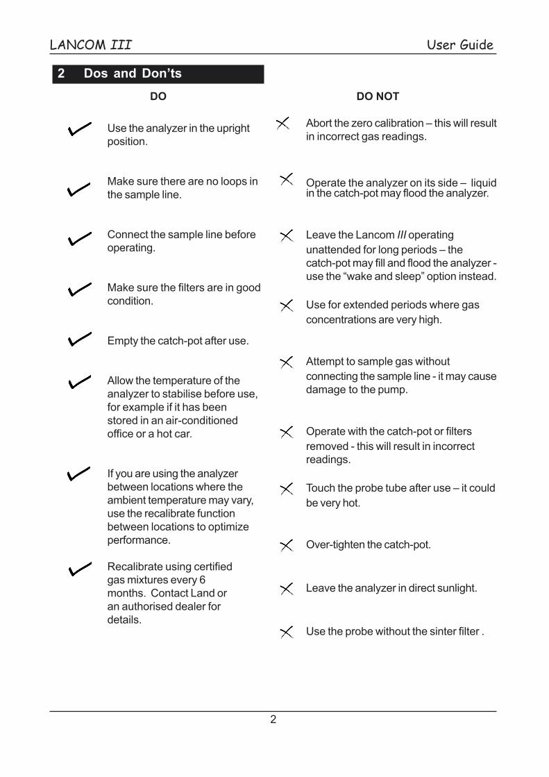
4.1 Changing the Printer Header andFooter
There are 4 lines of text available for theheader. The footer has 2 lines. Each line hasa maximum of 24 characters.
1 From the main menu select:
SET-UP>PRINTER>CURRENT HEADER.
2 Use the keys on the control panel toenter text.
Left and right keys movethe cursor.
Up and down keyschangethe characterunder the cursor.
Enter moves the cursorto the next line of text.
3 Press NEXT (F4) to display theCURRENT FOOTER. Use thesame method to change the footerand press ENTER to complete.
4 Press ABORT (F3) to exit thisscreen without applying changes.
4.2 Setting the Date and Time
The date format is DAY:MONTH:YEAR.
1 From the main menu select:SET-UP > DATE & TIME
2 Use the up and down arrow keys tochange the day.
3 Press the right arrow key to move thecursor to the month and use the upor down arrow key to change thevalue.
4 Press the right arrow key to move thecursor to the year and use the up ordown arrow key to change the value.
5 To change the time press ENTER orpress EXIT (F1) to leave this screenwithout changing the time.
6 Change the hour and then use theright arrow key to move to the cursorto the minutes column. Change theminutes using the up or down arrowkey.
7 Press EXIT (F1) to save the new dateand time.
4.3 Configuration for CombustionEfficiency MeasurementFuel efficiency, loss and excess air aredisplayed on the GAS READINGS screen andalso appear on printouts and in data logs.
To measure fuel efficiency thecorrect fuel type must be specified.
Setting the Fuel Type:
SET-UP > FUEL TYPE >
WOOD - LIGHT FUEL OIL - HEAVYFUEL OIL - NATURAL GAS - PROPANECOAL - 4 USER SPECIFIC FUELS
The values required to calculate fuel efficiencyare shown in SET-UP > FUEL DATA andcannot be changed. Fuel efficiency values arenot available when using the high temperatureprobe. Four blank fuel types are provided forcustomization. Contact LAND or an approveddealer for advice.

5
User Guide LANCOM III
To Enable Wet Analysis
Normally the gas readings are given on a �dry�basis. Wet analysis can be enabled andrequires the water content of the flue gas tobe entered.
1 From the main menu select:
SET-UP > SYSTEM > NEXT (F4)> ANALYSIS
2 Press the up arrow key to changethis option to WET and pressENTER.
3 You must enter the water content.Press the ENTER key twice tohighlight the WATER option.
Use the up or down arrow key tochange this value and then pressENTER.
Oxygen Normalization
Oxygen normalization can be enabled ordisabled from the control panel.
1 From the main menu select:
SET-UP > SYSTEM>NEXT (F4) >O2 NORMALIZATION -use the
ENTER key to scroll through theoptions.
2 Use the arrow keys to change thisoption to YES or NO.
3 If you have enabled oxygennormalization you must enter theoxygen normalization factor. Pressthe ENTER key to highlight the O2FACTOR option and use the arrowkeys to change this value and thenpress ENTER.
NO2 Factor
If a NO2 sensor has not been fitted to the
analyzer the NO2 factor is be used to
calculate NOX from the NO reading.
SET-UP > SYSTEM > NO2 FACTOR
Changing the Measurement Units
Temperature Units
SET-UP > SYSTEM > TEMPERATURE:Celsius, Fahrenheit
Gas Concentration Units
SET-UP > SYSTEM > DISPLAY UNITS:mg/Nm3, ppm , ng/J, lb/mmBtu
Units of Pressure (Draft Readings)
SET-UP > SYSTEM >UNITS OF PRESSURE: wgc, hPa
Hydrocarbon Concentration Units
SET-UP > SYSTEM > CxHx UNITS:%, ppm
Mass Flow Units
SET-UP > FLOW > MASS FLOW UNITS:lbs/min, lbs/hr, kg/hr, kg/min, tons/yr
4.4 Configuration for Emissions Monitoring

6
LANCOM III User Guide
5 Operating Your Analyzer 4 Insert the probe into the stack � seeUsing the Standard Probe page 7.
5 When zero calibration is completeselect GAS READINGS.
6 Press GO (F3) to begin sampling.
The current gas readings are shownon the display. Press ENTER to seefurther screens of information.
Wait about 3 minutes for the gasreadings to settle before yourecord them.
7 When the gas readings havestabilised you can print or log them.
8 To display the mass flow rates pressFLOW (F2) on the gas readingsscreen. To display gasconcentrations again press STD(F2).
Stopping Gas Sampling WithoutTurning Off the Analyser
1 From the main menu select:PURGE & PUMP OFF.
2 The analyzer will stop sampling andpass air through the gas sensors forabout 30 seconds (Air purging).
3 When you are ready to startsampling select GAS READINGSand press GO (F3).
1 Sample line2 Thermocouple3 On/off key4 Sample line release
Each time you use your analyzer check:
The catch-pot is empty and securely fastened.The catch-pot must be air tight.
The battery is fully charged (or use the powerlead).
There is sufficient printer paper . See page13.
Operating Instructions
1 Connect the sample line (1) andthermocouple (2).
2 Switch on the analyzer.
3 Wait for the analyzer to completethe zero calibration.
Do not abort the zerocalibration.
1
2
3
4
Mass Flow Readings
Follow the set up procedure for mass flowbefore using mass flow rates - seeUnderstanding Mass Flow page 22.
7
User Guide LANCOM III
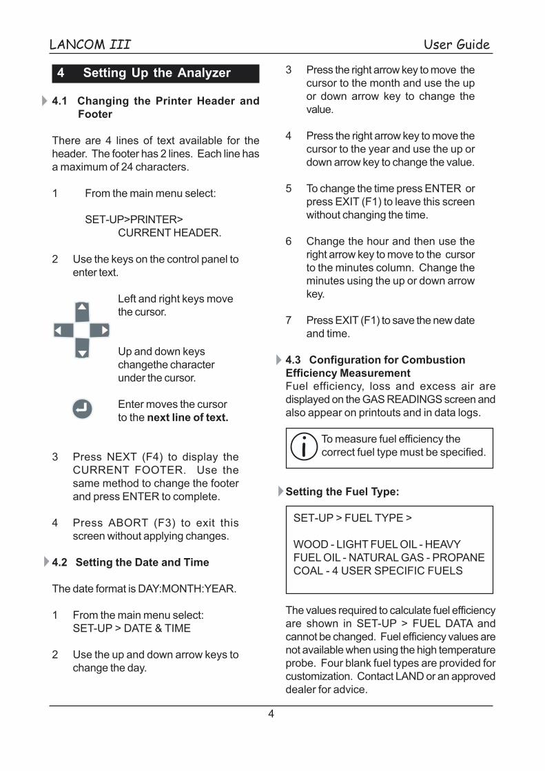
Using the Standard Probe
The probe should be inserted into the gas flowthrough a suitably sized sample port.
Probe Type Port DiameterMinimum Maximum
Standard 11 (7/16�) 16 (5/8�)Flow 40 (1.6�) 55 (2.2�)High Temperature 11 (7/16�) 16 (5/8�)DrySampler 11 (7/16�) 16 (5/8�)Smoke 11 (7/16�) 19 (3/4�)
The sealing cone should form a seal in thesample port to prevent the ingress of air(which may give a false gas reading). Thesealing cone can be moved along the probepipe to position the probe tip.
You can use a piece of heat proof fabric toimprove the seal. To sample gas successfullythe probe tip should be positioned in the maingas flow.
Emptying the Catch-pot
1 Pull OUT the catch-pot from the clip.
2 Remove the catch-pot by gentlyturning clockwise.
3 Empty the catch-pot. To avoid airleaks when replacing the catch-potmake sure the gasket is still inposition (see page 17) and thecatch-pot is securely fitted.
Do not over-tighten thecatch-pot.
Damage or cracking to the catch-pot cancause leaks which will affect the accuracyof the gas readings.
MENU
02 10.3%
PBE. TEMP 171°C
HELP EXIT
Enlarging the Display
1 In the GAS READINGS screenpress ENTER.
Press ZOOM (F3)
2 The up arrow key scrolls throughthe measurements displayed onthe top line and the down arrow keythose on the bottom line.

8
LANCOM III User Guide
6 Recording Gas Readings
Gas readings can be printed immediately orstored in memory.
Data logging stores gas readings in theLANCOM III �s memory. This allows you toprint the data logs or to download them usinga personal computer.
If you need to make gas readings over alonger period use the Wake and Sleep option(page 10).
Data Averages Reporting
The LANCOM III calculates the averagereadings from the stored data logs.
An average report appears at the end of thedata log printout.
Where readings are sent directly to the printerno average report is created.
6.1 Printing Gas Readings
1 In the main menu select:
GAS READINGS
2 Press PRINT (F3)
3 A print out of the current gas datais produced.
6.2 Using Data Logging
The LANCOM III �s data logging facility hastwo settings: manual and automatic.
You can save about 930 logs.
A data log contains:
Date and TimeFuel TypeUnit NumberWet/Dry AnalysisO2 Normalization On/OffAmbient TemperatureFlue Gas TemperatureGas or Mass Flow ReadingsNOx ConcentrationCO2 ConcentrationFuel EfficiencyExcess AirPercentage WaterO2 Normalization Factor
Using Manual Data Logging
1 From the GAS READINGS screenpress LOG (F4).
The above details are saved.
2 When you are ready to log the nextset of gas readings press LOG(F4) again.
Data print out Calculated averagevalues report

9
User Guide LANCOM III
Automatic Data Logging
Automatic data logging allows you to specifythe number of logs you need and how oftenyou make them. You can store the logs to thememory or print them as they are made.
Examplelogging the gas readings every 10seconds (LOG INTERVAL) for aduration (LOG PERIOD) of 2 minutesgenerates 12 data logs.
Setting Up Automatic Data Logging
1 Select DATA LOG>LOG SET-UP.
2 Use the up arrow key to change theLOG TYPE to AUTOMATIC andpress ENTER.
3 Choose the destination for thelogged data:
MEMORY data logs are stored in memoryand can be retrieved later.
PRINTER data logs are printed as they aremade. Data logs are not stored. TheLOG INTERVAL must be set 30 seconds orover when printing directly.
RS232 this is available for downloadingdirectly to a personal computer or printerconnected to the serial port. If you selectRS232 you must also set LOG OUTPUT todetermine the data format.
4 Enter the LOG PERIOD - the totaltime during which all the data logswill be stored. This can be between2 and 60 minutes.
5 Enter the LOG INTERVAL - the timebetween each data log. This can bebetween 10 and 1800 seconds anddetermines the number of data logsmade.
Using Automatic Data Logging
1 Connect the probe.
2 On the GAS READINGS screenpress GO (F3).
3 Press AUTO LOG (F4) to startautomatic data logging.
4 Data logging will stop automaticallywhen the LOG PERIOD has elapsedor when STOP LOG (F4) ispressed.
5 When automatic data logging iscomplete data logging returns tomanual operation.
Deleting Data Logs
Caution - this clears all datalogs from the memory.
1 From the main menu select:
DATA LOG > CLEAR LOG
6.3 Downloading Data Logs
1 To print all of the data logs select:
DATA LOG > OUTPUT TO PRINTER
2 To download data to a personalcomputer (for example runningHyperTerminal) or a connectedserial printer select:
DATA LOG > OUTPUT TO RS232.
3 To stop downloading press andhold down the ABORT key.
If your personal computer is runningLand�s Insight software you candownload data logs directly. See yourInsight manual for more details.

10
LANCOM III User Guide
6.4 Using Wake and Sleep
The LANCOM III is not designed to be usedcontinuously, however the Wake and Sleepoption makes gas readings periodically andturns the analyzer on and off automatically.This prevents the gas sensors from beingpoisoned by prolonged exposure to flue gas.
How �Wake and Sleep� Works
1 When Wake and Sleep is enabledthe analyzer will purge for about 3minutes to remove remainingsample gas from the sensors.
2 The analyzer will now �sleep� until theFIRST WAKEUP TIME.
3 At the FIRST WAKEUP time theanalyzer will automatically begin azero calibration.
4 The analyzer begins to sample fluegas.
5 There is a 3 minute delay to allowthe gas readings to settle before thefirst gas reading is taken.
6 After the SAMPLE INTERVAL thenext gas reading is taken.
7 When the total number of sampleshave been taken the analyzer willpurge sample gas from the gassensors and then �sleep� for theremainder of the WAKEUPINTERVAL.
8 This sequence will be repeatedautomatically at the next WAKEUPINTERVAL until the ABORT key(F1) is pressed.
When should I use the Wake and Sleepoption?
When you need to monitor gas emissions overan extended time period.
Using the Wake and Sleep option has severaladvantages:
Saves battery life.
Helps to prevent the catch-pot fromoverflowing into the analyzer.
Prolongs the life of the gas sensors.
Allows the analyzer to be left unattended.
11
User Guide LANCOM III
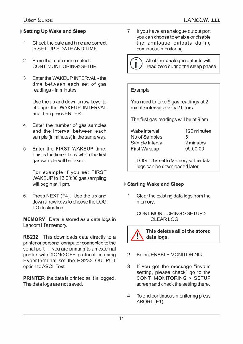
Setting Up Wake and Sleep
1 Check the date and time are correctin SET-UP > DATE AND TIME.
2 From the main menu select:CONT. MONITORING>SETUP.
3 Enter the WAKEUP INTERVAL - thetime between each set of gasreadings - in minutes
Use the up and down arrow keys tochange the WAKEUP INTERVALand then press ENTER.
4 Enter the number of gas samplesand the interval between eachsample (in minutes) in the same way.
5 Enter the FIRST WAKEUP time.This is the time of day when the firstgas sample will be taken.
For example if you set FIRSTWAKEUP to 13:00:00 gas samplingwill begin at 1 pm.
6 Press NEXT (F4). Use the up anddown arrow keys to choose the LOGTO destination:
MEMORY Data is stored as a data logs inLancom III�s memory.
RS232 This downloads data directly to aprinter or personal computer connected to theserial port. If you are printing to an externalprinter with XON/XOFF protocol or usingHyperTerminal set the RS232 OUTPUToption to ASCII Text.
PRINTER the data is printed as it is logged.The data logs are not saved.
7 If you have an analogue output portyou can choose to enable or disablethe analogue outputs duringcontinuous monitoring.
All of the analogue outputs willread zero during the sleep phase.
Example
You need to take 5 gas readings at 2minute intervals every 2 hours.
The first gas readings will be at 9 am.
Wake Interval 120 minutesNo of Samples 5Sample Interval 2 minutesFirst Wakeup 09:00:00
LOG TO is set to Memory so the datalogs can be downloaded later.
Starting Wake and Sleep
1 Clear the existing data logs from thememory:
CONT MONITORING > SETUP >CLEAR LOG
This deletes all of the storeddata logs.
2 Select ENABLE MONITORING.
3 If you get the message �invalidsetting, please check� go to theCONT. MONITORING > SETUPscreen and check the setting there.
4 To end continuous monitoring pressABORT (F1).

12
LANCOM III User Guide
Downloading Wake and Sleep Data Logs 6.5 Making Draft Readings
The DRAFT READING represents thedifferential pressure between the stackpressure (taken at the probe tip) and ambientpressure. Draft readings are made with astandard probe.
To check the draft reading insert the probeinto the stack. From the main menu select:
DRAFT READING
The draft readings is displayed on the screenbut cannot be recorded or printed.
To change the units see page 5.
The draft sensor must be recalibrated every6 months. Contact LAND or an approveddistributor for more details.
6.6 Zero Calibration
The analyzer automatically performs a zerocalibration when it is switched on.
If you are using the analyzer in differentlocations where the temperature difference issignificant perform a zero calibration beforemaking a gas reading in each location.
You do not need to remove the probe fromthe stack or disconnect it to perform a zerocalibration.
To perform a zero calibration select
RECALIBRATE and press ENTER.
Do not ABORT the zerocalibration.
For optimum performance a spancalibration should be carried outevery 6 months using certified
calibration gases - contact LAND or anapproved distributor for more details.
Data logs can be retrieved when Wake andSleep is complete (unless you set LOG TOas PRINTER).
Printing Data Logs
1 From the main menu select:
CONT MONITORING >OUTPUT TO PRINTER
2 Printing starts when you press theENTER key.
Downloading to a Personal Computer
1 To download data to a personalcomputer (for example runningHyperTerminal) select:
CONT MONITORING >OUTPUT TO RS232
2 Press ENTER to start downloading.
Text in this format cannot be used in spreadsheet or word processing packages.
If your personal computer is running Land�sInsight software you can download datalogs directly. See your Insight manual formore details.
Printing to an External Printer
1 To print to a printer connected tothe serial port select:
CONT MONITORING >OUTPUT TO RS232
2 Printing starts when you press theENTER key.

13
User Guide LANCOM III
A glossy side of paper
7 Maintenance Procedures
The LANCOM III requires very littlemaintenance.
Routine maintenance is very simple andrequires no special tools.
To get the maximum performance from youranalyzer follow these guidelines:
1 It is recommend that your analyzer isrecalibrated every 6 months. Forfurther information contact LandInstruments International or anauthorised dealer.
2 Do not ignore the service light.
3 Follow the instructions in theMaintenance Schedule when theservice light comes on.
4 Wherever possible operate theanalyzer inside its bag to protect it.
5 Do not use continually when gasconcentrations are high.
6 Don�t operate for extended periods- use the Wake and Sleep option.
7 Empty catch-pot regularly to avoidliquid entering the analyzer.
8 Check the condition of the catch-potand filters regularly.
7.1 Changing the Printer Paper
1 Remove the side panel byreleasing the two screws .
2 Loosen the retaining screw and takeout the spindle.
3 Remove the empty printer roll.
4 Slide new paper roll onto spindle.
The paper roll should bereplaced so that the glossy side(A) appears at the top when itleaves the printer.
5 Replace the spindle and tightenscrew (A).
panel screws
printer
A

14
LANCOM III User Guide
7.3 Recharging the Batteries
The Low Batt light on the control panelilluminates when the batteries needrecharging.
Do not remove the batteries. Connect theanalyzer to the mains power supply.
The batteries will recharge while the analyzeris switched off. The charging light on thecontrol panel will be illuminated.
A full recharge will take about 8 hours.
To Check the Battery Power
1 From the main menu select:
DIAGNOSTICS > SYSTEM
When fully charged the battery will readbetween 12.5 and 12.9 Volts. This issufficient for about 8 hours use.
When the battery voltage falls below 11.5 Voltsthe Low Batt light will illuminate.
If the battery voltage falls below10.5 Volts the analyzer will shutdown.
6 Cut the edge of the paper at a slightangle.
7 Thread the paper edge under theblack roller into the printer.
8 The paper feeds automatically intothe printer.
7.2 Clearing Paper Jams
1 Press down the green paperrelease latch (C) release the paperroller.
2 Pull out the jammed paper.
3 Cut the edge of the paper andthread it back into the printer.
power supplyconnection
A Spindle screwB Paper advance keyC Paper release

15
User Guide LANCOM III
7.5 The Service Light
The filter counter measures the amount of SO2
and NOx passing through the analyzer. Whenthe filter count reaches 120 000 ppm.mins theservice light comes on.
The current filter count is displayed inDIAGNOSTICS > FILTER
When the service light comes on carry out thefollowing before you use your analyzer again.
1 Replace the CO compensation filter- see page 16 and 17 for details.
2 Inspect the analyzer as described inthe maintenance schedule page 16.
3 Reset the filter counter.
Resetting the Filter Counter
1 From the main menu select:
SET-UP > SYSTEM >CLEAR FILTER COUNTS
2 The service light will go out.
7.4 The Fault Light
If the Fault light illuminates check thediagnostics screen. Contact LAND or anapproved distributor.
1 From the main menu selectDIAGNOSTICS > SYSTEM
2 Use the NEXT (F4) to reach theSYSTEM FAULTS screen (5thscreen).
3 Check the fault list - print out theSYSTEM REPORT you may beasked to provide it to aid diagnosis.
Printing a System Report
1 From the main menu select:DIAGNOSTICS > REPORT
2 Select the destination (PRINTER)and press REPORT (F4)
Clearing Faults
1 From the main menu select:
SET-UP > SYSTEM > CLEAR FAULTS
The fault light will go out.
Fault Report Action
Invalid parameter Memory fault. Contact Land.X compensation fault Calculation error. Contact Land.ADC fault Faulty ADC. Contact Land.Printer buffer overrun If problem persists contact Land.Zero O2 readings following recal Oxygen sensor failed - replace sensor. ContactLand.Checksum error Memory fault. Contact Land.Main battery low Recharge batteries. See page 14.Filter change recommended Change filters and reset the filter counter.

16
LANCOM III User Guide
* Reset the filter counter whenever you replace the CO compensation filter (page 15).
Sinter filter702.182
Gas pre-filter703.144
*COcompensationfilter703.145
Catch-pot701.828
Item Check
Keep the sinter filter clean. After use allow to cooland clean with a wire brush and a mild detergent.
Replace if it is cracked or corroded.
Do not operate with the sinter filter removed.
Replace if
the filter is dirty or discoloured.
the plastic casing is cracked or opaque.
Replace if
the service light illuminates.
the filter granules begin to turn white.
the plastic casing is cracked or opaque.
Replace if cracked or damaged.
Check the gasket (319.250) is still in place insidethe hinged section.
Remove the probe from the handle and check theo-ring, replace if damaged.
7.6 Maintenance Schedule
Probe o-ring319.211
Upgrading Your Analyzer
Upgrades normally require the analyzer to be returned to LAND, however if you have a personalcomputer (or a laptop) with an Internet connection it is possible to perform upgrades remotely.
To perform upgrades remotely you will need a copy of the GASS software (available onrequest) a serial cable and the addition parts.

17
User Guide LANCOM III
7.7 Maintenance Instructions
Changing the Filters
1 Push over the wire clip and removeeach filter.
2 Remove the two protective capsfrom each replacement filter.
3 To avoid air leaks make sure thefilters are pushed fully into theanalyser.
4 Pull the wire clip over each filter.
When you have replaced the filtersreset the filter counter. See sectionThe Service Light page 15.
The filters must be replacedin the correct position.
Standard Probe
Item Description Part NumberA O-ring 319.211B Sinter filter 702.182C Catch-pot assembly 704.344D Gasket 319.250E Catch-pot 701.828
A
B
DC
E
wire clip
CO compensationfilter
gas pre-filter
This way up

18
LANCOM III User Guide
Sinter filter for standard probe 702.182 Sample line connector 317.109
Gas pre-filter 703.144
Other Spare Parts
CO compensation filter 703.145
8 Spare Parts
1 2
3
Spares kit containing items 1 to 4 - 703.314
4
Printer Paper 405.109
Flow meter for calibration 703.935
Catch-pot with hinge (left) 704.344Catch-pot (right) 701.828Catch-pot gasket (not shown) 319.250

19
User Guide LANCOM III
Filter papers (above) 701.616Bacharach Greyscale Charts 702.035
o-ring for standardprobe 319.211
Standard Probe Handle and Hose3 m 10 ft 703.12810 m 32 ft 703.163
Replacement steel probe pipe for standardprobe
300 mm 12� 702.1411 m 3 ft 702.2051.5 m 5 ft 702.2062 m 6 ½ ft 703.4403 m 10 ft 702.207
Spare Parts for Probes
Standard Probe Smoke Probe
Seal for hightemperature probe704.189
Replacement mullite (ceramic) probepipes for High Temperature Probe.
300 mm 12 � 305.001500 mm 20 � 305.002750 mm 29 ½ � 305.0031 m 3 ft 305.0041.5 m 5 ft 305.0053 m 10 ft 305.006
High Temperature Probe Drysampler Probe
Box of twenty ice packs 321.033Body assembly 323.350Catch pot 323.351Heat exchanger assembly 323.352Viton O-ring 323.353

20
LANCOM III User Guide
9 Using the Smoke Probe
Measuring the sample flow rate
The flow rate of the sample gas through theprobe will determine the sample time used tomake the smoke measurement.
1 Connect the smoke probe.
2 Connect a flow meter to the exhaustport.
3 From the main menu select:SMOKE.
4 Insert the probe into the sample portand press GO (F4).
5 Use the flow meter reading todetermine the sample time from thetable. Do not disconnect the flowmeter.
Sample Times for Land Smoke Probe
0.4 2400.5 1920.6 1600.7 1370.8 1200.9 1071 961.1 871.2 801.3 741.4 69
Flow Rate(L/min)
1.5 641.6 601.7 571.8 531.9 512 482.1 462.2 442.3 422.4 402.5 38
SampleTime (s)
SampleTime (s)
Flow Rate(L/min)
Making the smoke measurement
1 From the main menu select:
SET-UP > SYSTEM >SMOKE MEASUREMENT
2 Enter the sample time from the table.
3 Return to the main menu and select:
SMOKE
4 Insert the filter paper into the smokeprobe. Wait for the probe to warmup and then press GO (F4).
5 The sample flow rate should remainconstant throughout the smokemeasurement time. If the sampleflow rate drops significantly removethe filter paper and repeat the test.
6 When the smoke measurement iscomplete remove the filter paper.
7 Compare the filter paper with theBacharach Smoke Scale.
filter paper cartridge
sample line
connectflow meter
thermocouple
Example
It the flow meter reads 0.7 litres perminute set SMOKE MEASUREMENTto 137 seconds.
The heated smoke probe will operate fromfully charged batteries for a maximum of 20minutes.
If you intend to use the smoke probe for longerperiods use a mains power supply.

21
User Guide LANCOM III
10 Using the High Temperature Probe
Assembling the High TemperatureProbe
1 Loosen the sealing cone (2).
2 Slide probe pipe (1) through thesealing cone (2) and seal (3) andcarefully tighten the sealing cone(2).
When replacing a probe pipe,remove the seal (3) and clear anydebris before replacing the probepipe.
3 The position of the probe handle (7)can be adjusted. Loosen the topretaining screws and reposition thehandle. Tighten the screwssecurely.
Using the High Temperature Probe
1 Connect the sample line (5) to theflue gas port on the analyzer.
2 From the main menu select:
GAS READINGS > GO (F3)
The high temperature probe is used in thesame way as a standard probe.
The Land High Temperature Probe can be usedin flue gas temperatures up to 1400°C(2552°F).
The High Temperature Probe is used in thesame way as the standard probe, however itcannot be used to measure fuel efficiency asthe gas temperature is not measured.
The Probe Pipe and HeatShield become HOT whenin use.
Connect the sample line tothe port marked �Flue Gas�
1 Probe pipe2 Sealing cone3 Seal (704.189)4 Handle assembly
5 Sample line6 Heat shield7 Adjustable handle
4
5
7
6
2 31
See page 7 for a table of entry portdiameters.

22
LANCOM III User Guide
11 Using the DrySampler Probe
Once assembled the DrySampler probe isused in the same way as the standardprobe.
1 Make sure thecatch-pot (5) has beenemptied, and is secure.
2 Unscrew thecoolant pot (7) andremove it.
3 Follow the instructions on the ice packto activate it.
The ice pack containsammonium nitrate and waterand is corrosive. If contentsleak, rinse coolant pot withwater. Avoid contact withskin and clothing.
4 Carefully roll the ice pack and insert itinto the coolant pot (7). Replace thecoolant pot by threading the impinger(6) through the ice pack, taking carenot to puncture it. It is simpler toreplace the coolant pot with the o-ringremoved. Store the o-ring on top ofthe impinger (6).
5 The ice pack will be effective forapproximately half an hour. Shake thepack occasionally to extend this time.
6 Connect the sample line (4) andconnector (3) in the normal way. Theprobe is now ready for use.
7 After use, remove the ice pack(follow the manufacturesinstructions for disposal) andempty the catch-pot.
When emptying the catch-potthe contents may be corrosive.
*An alternative cooling medium, such asiced water may be used.
2
3
5
7
6
1
8
41 Probe collar2 Probe3 Thermocouple4 Sample line5 Catch-pot6 Impinger7 Coolant pot8 *Cool pack (321.003)
See page 7 for a table of entry portdiameters.

23
User Guide LANCOM III
12 Understanding Mass Flow
The flow probe is used to measure the velocityof the flue gas not the mass flow rates.
Mass flow rates can be measured with astandard or Drysampler probe.
To measure mass flow rate you must knowthe velocity of the flue gas in the stack. If youknow this you can enter it from the controlpanel.
If you do not have this information you can usethe Land�s Flow Probe to measure it.
You must enter the following information.
PRESSURE - atmospheric pressure.
WATER - the percentage water content of theflue gas.
DUCT AREA - the cross sectional area of theduct.
FLUE GAS TEMPERATURE - this must beentered manually if you are not using the flowprobe.
There are two steps to making a mass flowmeasurement.
1 Measure the flue gas velocity ofthe gas in the stack from the locationyou will make the mass flow reading.The measured velocity is stored inthe analyzer.
2 Use the standard probe in thenormal way to measure gasconcentrations. Mass flow iscalculated from the measured gasconcentration using storedinformation.
To Enter the Flue Gas Velocity from theControl Panel
1 From the main menu select FLOW
Enter all of the informationrequired on this screen.
Probe K Factor 1.422
The density correction factor 1(unless an accurate densitycomparison can be made).
2 Press
NEXT (F4) > MANUAL (F3)
3 Press F2 select the temperatureunits before you enter the value.Press enter to confirm.
4 Press F3 to change the duct velocityunits before you enter the value.
5 Press EXIT (F1) to save settings.
6 Press MENU (F1) to return to themain menu.
To get an accurate mass flowmeasurement you must takethe gas readings from the samelocation as the flow probe.

24
LANCOM III User Guide
Using the Flow Probe to Find the FlueGas Velocity
Do not insert the probe into thestack until step 6.
1 From the main menu select FLOW.
2 Enter all of the information requiredon this screen.
Probe K Factor 1.422
The density correction factor 1(unless an accurate densitycomparison can be made).
3 Connect the flow probe - but do notinsert the probe into the stack untilstep 6.
4 Press NEXT (F4) > GO (F4)
The flow measurements will bedisplayed on the screen.
5 Press ZERO (F3) and wait for theflow reading to stabilise.
6 Now insert the flow probe into thestack using the sealing cone toposition it.
7 Press STORE (F4) to record theflow measurements.
Press F2 to change the units: cubic feet persecond or cubic metres per second.
The instrument is now ready to make massflow readings using a standard probe.
To zero mass flow readings pressZERO (F3) and then STORE (F4).All mass flow readings on the GASREADINGS screen will be shownas zero.
1 Clear pipe2 Black pipe3 Thermocouple
The probe must be positioned in the stack sothat the probe tip is facing directly into the gasflow. The �direction of flow� arrow on thehandle can be used as a guide once the probehas been inserted into the stack.
probetip
direction ofgas flow
See page 7 for atable of entry portdiameters.
directionof flow

25
User Guide LANCOM III
13 Output Options
13.1 Analogue Outputs
OP12
OP11
OP10
OP 9
OP 8
OP 7
OP 6
OP 5
OP 4
OP 3
OP 2
OP 1
13 12 11 10 9 8 7 6 5 4 2 1
25 24 23 22 21 20 19 18 17 16 15 14
3
GROUND/RETURN
Channel Output Pin Designation Number Number
1 OP1 14 CO low2 OP2 15 CO high3 OP3 16 SO2
4 OP4 17 O2
5 OP5 18 NO2
6 OP6 19 NO7 OP7 20 HxCy8 OP8 21 H
2S
9 OP9 22 CO2
10 OP10 23 *11 OP11 24 *12 OP12 25 *
*set these individually to: calculated fuel efficiency,calculated fuel loss, calculated excess air, calculatedtotal NOx, flue temperature or ambient temperature.
Where a gas sensor is not fittedthe output from the respectivechannel will be zero.
The analogue outputs are set to zero duringthe �sleep� phase.
Analogue Output Ranges
The ranges for each of the 12 channels canbe set independently.
1 From the main menu select:
SET-UP > ANALOGUE O/P
2 Use the arrow keys to change theminimum and maximum values andpress ENTER to move the cursor tothe next line.
3 Press NEXT (F4) to step through thechannels.
Units of Measurement
Outputs 4, 7 and 9 are designated as apercentage concentration.
The units of all other outputs is defined in SET-UP > SYSTEM > DISPLAY UNITS.
13.2 Serial Communications
A serial port is provided to allowcommunication with a personal computer orprinting to an external printer. A cable issupplied with the Insight software.
A standard cable can be used to connect toan external printer. Land part number203.873.
It is not normally necessary to change theserial port settings. You can check or changethese settings by selecting
Language Display Options
The menu can be displayed in otherlanguages:
English, French, German, Italian, Polish, andSpanish
To change the display language.
1 From the main menu select:
2 SET-UP > LANGUAGES
3 Use the up or down arrow key tochange the language and pressENTER to confirm.

26
LANCOM III User Guide
Continuous product development may make it necessary to change these details without notice.
14 Technical Specification
Range
Gas sensors Range Accuracy ResolutionOxygen, O
20 to 25 % Vol ±1 % ±0.1 % Vol
Carbon Monoxide, CO Low 0 to 2000 ppm ±2 %* ±1 ppmCO, (H
2 compensated) 0 to 2000 ppm ±2 %* ±1 ppm
Carbon Monoxide, CO High 0 to 4 % ±2 %* ±1 ppmSulphur Dioxide, SO
20 to 2000 ppm ±2 %* ±1 ppm
Nitric Oxide, NO 0 to 1000 ppm ±2 %* ±1 ppmNitrogen Dioxide, NO
20 to 100 ppm ±2 %* ±1 ppm
Carbon Dioxide, CO2 ** 0 to 25 % Vol ±0.5 % Vol.* ±0.1 % Vol.
Hydrogen Sulphide, H2S 0 to 200 ppm ±2 %* ±1 ppm
Hydrocarbons CxHy 0 to 5.0 % Vol Application dependent
Flue Gas Temperature Measured 0 - 1000 °C ±5 °C / 1832 °F ±41 °FAmbient Temperature Measurement over full rangeDraft*** ±51 cm / 20 � water gaugeCarbon Dioxide, CO
2Calculated where no sensor is fitted
Efficiency CalculatedExcess air CalculatedLoss CalculatedFlow Measurement (velocity) 1 to 50 m/s
* Calibration per CTM034 or LAND factory procedure** True measurement where sensor fitted (calculated where not)*** reduced to ±26 cm / 10 � water gauge when used with the flow probe.
Special ranges must be requested at the time of purchase.
Fuels Wood - Light Fuel OilHeavy Fuel OilNatural gasPropane - Coal -4 User definable fuels
Power Supply 95 - 265 V a.c. +10 %,50-60 Hz, 30 Watts.
Rechargeable 2 x 6 V 4 Amp.hours.battery
Operating -5 to 45 oC / +23 to 113 oFTemperature Range
Maximum Probe Temp 600 oC/1112 oF continuousfor Standard probe 1000 oC/1832 oF intermittent
Weight 6 kg / 13 lbs
Dimensions 453 mm x 120 mm x 245 mm17.8 � x 4.7 � x 9.6 �

27
User Guide LANCOM III
15 Calibrating the Analyzer
15.1 Automatic Zero Calibration
When the analyzer is switched on itautomatically performs a zero calibration.
Do not abort the zero calibration.
Ambient air is drawn through a vent in theanalyzer and is used for zero calibration. Thismeans it is possible to perform a zerocalibration with the probe connected.
15.2 Important Safety Information
Calibration gas is dangerous. You mustcomply with local health and safety and fireregulations.
Calibration gases must be obtained from areliable supplier. Calibration gas contains asmall amount of the measured gas usually ina balance of nitrogen (there are someexceptions).
15.3 Calibration Gas Concentration
Calibration gas is purchased with a nominalconcentration accuracy of ±5%. It is thencertified by the gas filler to the actualconcentration accuracy ±2%.
This information is provided on a certificatewhich accompanies the cylinder and is thevalue which must be entered into theinstrument.
Usually gas cylinders are filled to between100 and 200 bar (1450 and 2900 psi). Usingcalibration gas at this pressure will causeserious damage to the instrument. Read theinstructions carefully.
A pressure regulator must be supplied toadjust the calibration gas pressure to 0.7 bar(10 psi).
Use a calibration gas concentration ofbetween 70 and 100% of the gas sensorrange.
For example to calibrate a gas sensor with arange of 0 to 1000 ppm a calibration gas witha concentration of 750 ppm would be suitable.
Calibration Gas Required
Gas Sensor Gas Required
CO (H2 compensated) CO and H
2
CO low COCO high COSO
2SO
2
O2
*noneO
2 zero gas CO (in N
2)
NO2
NO2
NO NOCxHy methaneH
2S H
2S
CO2
CO2
CO2 zero gas N
2
Calibration gas is expensive anddelivery time can be long. Checkwith your local supplier beforeordering gas.
*Ambient air is used to calibrate the oxygen sensor.Connect a hose connector (Land part number317.109) to the flue gas port on the control panel.

28
LANCOM III User Guide
15.4 Getting Ready for Calibration
Hydrogen Compensated Calibration
Where a CO hydrogen compensated gas sensor is fitted the sensormust also be calibrated using hydrogen.Select hydrogen from the menu and continue as for normalcalibration.
1 Calibration gas cylinder2 Control valve3 Pressure gauge4 Flow meter Land part number 703.9355 Vent for calibration gas � vent externally6 Exhaust � vent externally7 Flow (not used for calibration)8 Calibration gas connection (flue gas)
Land part number 317.109
The pipework should be arranged so that there is minimal gas flow atpoint 8. To avoid pressurising the analyzer use a flow meter which doesnot have a needle valve.

29
User Guide LANCOM III
15.5 Performing a Span Calibration
The GASS Software can also beused to perform a calibration.
Refer to the GASS Instruction Manual.
1 Make sure you have a list of thecalibration gas concentrations - youwill need to enter these values duringcalibration.
2 Check that the exhaust extraction isfunctioning correctly.
3 Before your begin calibrating,perform a zero calibration. SelectRECALIBRATE from the main menu.
4 When zero calibration is completeconnect the calibration gas supply tothe flue gas port on the analyser.
5 Set the pressure regulator on thecalibration gas cylinders to 0.7 bar(10 psi) and turn on the gas supply.Ensure flow at flow meter (4).
6 From the main menu select MANUALCAL.
7 Use the up arrow key to display thepassword and then press ENTER.
8 Select the gas sensor you are goingto calibrate and press ENTER. Thesample pump will start.
CAL GAS 1170 ppmConnect the cal gas and use cursor keysto select the calibration gas concentration.Press ENTER when ready to cal.
9 Enter the calibration gasconcentration by pressing the up ordown arrow keys to change thedisplayed value and then pressENTER.
Press CAL to calibrate.
CO LOW 10 ppm
10 Wait for the gas reading to stabilise(3 to 5 minutes) and then press CAL(F3). Calibration of the gas sensoris now complete.
11 Use the EXIT key to return to theMANUAL CALIBRATION screen.
12 Turn off the calibration gas anddisconnect the calibration gascylinder.
13 Repeat this procedure for theremaining gas sensors.
14 When all of the gas sensors havebeen calibrated, the exhaustextraction should remain on forapproximately 10 minutes to removeremaining calibration gas.
15 When calibration is complete selectPURGE AND PUMP OFF.
16 Check the gain valuesDIAGNOSTICS > SYSTEM pressNEXT (F4) until the GAINS screenis displayed.
Sensor Minimum Maximum
CO low -1100 -1700CO high 30 000 45 000SO
21100 600
NO2
-400 -800NO -2200 -3200CxHy 14 000 18 000H
2S 708 1120
CO2
900 1250
If the value of a sensor is outside of thisrange then it must be replaced.
30
LANCOM III User Guide
15.6 Carbon Dioxide Sensor ZeroCalibration
The method for this zero calibration is thesame as for span calibration.
When performing a zero calibration it isimportant to use a calibration gas containingno CO
2.
Nitrogen or another calibration gas can beused, for example the calibration gas usedto calibrate the NO sensor. Do not use airas it contains approximately 400 ppm of CO
2.
15.7 Oxygen Sensor Zero Calibration
A zero calibration gas, for example CO in N2,
containing no oxygen is required for thischeck.
1 Connect the sample probe, or usea nylon hose connector in the fluegas connection.
The analyser should be samplingclean, fresh air.
2 From the main menu select GASREADINGS and then press GO(F3).
The oxygen reading should bebetween 20.7% and 21.2 %.
3 Press MENU (F1) to return to themain menu and selectDIAGNOSTICS.
4 Select CELL EMFS.
The oxygen sensor should bebetween 1.6 and 2 V. If the readingis out of this range replace theoxygen sensor.
5 Connect the analyser to thecalibration gas supply. Wait for thegas readings to settle, about 5minutes.
6 On the GAS READINGS screen, theoxygen value should be below 0.3%.
If this is not the case, check all of thepipe connections are tight both in theanalyser and in the test equipment,it is likely that there is an air leak.

31
User Guide LANCOM III
16 Glossary
Analogue Output SET-UP > SYSTEM >ANALOGUEOUTPUT: ENABLED, DISABLED. Either enables ordisables the analogue outputs if fitted.
Analysis See Wet Analysis.
Backlight Status AUTOMATIC. Determines how thescreen light will operate.
Backlight Timeout Numeric (1 to 180 minutes) Ifthe analyzer is switched on but has not been is usethe display will remain illuminated for the backlighttimeout period.
Clear Faults SET-UP > SYSTEM > CLEAR FAULTS:YES / NO. Set to yes to clear any faults � see section�The Fault Light�.
Clear Filter Counts SET-UP > SYSTEM > CLEARFILTER COUNTS: YES / NO. This resets the filtercounter (see filter counter) to zero and extinguishesthe service light.
CO2 Compensation SET-UP > SYSTEM > CO2COMPENSATION. The Oxygen sensor has a smallcross-sensitivity to CO
2 which is corrected
automatically. The normal value for CO2 Compensation
is 0.30. This value should only be changed on advicefrom LAND or an approved distributor.
CxHy Units SETUP>SYSTEM>CxHy UNITSDetermines whether the hydrocarbons reading isdisplayed in ppm or as a percentage.
Display Units SET-UP > SYSTEM > DISPLAYUNITS: ppm, mg, lb/mm/Btu. Change the display unitsof measurement which appear on the screen, inprintout and in data logs.
Dry Analysis � see Wet Analysis.
Efficiency The efficiency of different types of fuel:maximum amount of CO
2 in a given fuel; K1 and K2
factors; Vo(dry)/Ao and the F factor. The fuel data forthe given fuel types cannot be changed. There arefour blank fuel types, which can be used to create sitespecific fuel data.
Excess Air This indicates the amount of air not beingburnt in the process. This calculation is performed bythe instrument and is determined as with FuelEfficiency, by the use of various factors. See alsoFuel Data.
Filter counter The filter counter measures the actualamount of gas passed through the filters. When thefilter counter reaches 120 000 ppm.mins the servicelight comes on. Always reset the filter counter whenthe filters are replaced.
Flow Displayed on the gas readings screen, printoutsand data logs. This is a measurement of the volumetricflow. See Mass Flow.
Flue Temp The temperature of the flue gas asmeasured by the probe. This is used in the mass flowand efficiency calculations. Flue temperature cannotbe measured by the High Temperature probe.
Fuel Data SET-UP > SYSTEM > FUEL DATA. Theseconstants are used to calculate the fuel efficiency.
Fuel Efficiency SET-UP > SYSTEM > FUELEFFICIENCY. This should always be set to TYPE A.Calculated as a percentage, indicates the efficiencyof the combustion process. Fuel efficiency is shownon the gas reading display and also appears on theprintout and in data logs. The flue efficiency calculationis based on BS843:Part1:1987. Calculation isperformed using preprogrammed constants for eachfuel type See Fuel Data. Fuel efficiency cannot becalculated when using the High Temperature Probe.See also Loss.
Fuel Type SET-UP > FUEL TYPE. The fuel typeused at a specific measurement point. The optionsare: Wood, Light Fuel Oil, Heavy Fuel Oil, Natural Gas,Propane, Coal. Fuel Type must be specified if fuelefficiency is being measured. See also Fuel Efficiency.
Language SET-UP >LANGUAGE > ENGLISH. Thisselects the language types available to the user.Languages other than English must be requested whenordering. Alternative languages cannot be retrofitted.
Loss The loss indicates the inefficiency of the burnersand is displayed as a percentage. Loss is displayedon the gas readings screen, printouts and in data logs.
NO2 Factor SET-UP > SYSTEM. Where no NO2sensor is fitted the NO2 factor � the percentagecorrection required for calculated NOx readings mustbe entered.
O2 Factor SET-UP > SYSTEM > O2 FACTOR. Seealso Oxygen Normalization and O2 Normalization.This is the oxygen content � as a percentage � whichis required when oxygen normalization is ON.

32
LANCOM III User Guide
O2 Normalization SET-UP > SYSTEM > O2NORMALIZATION. See also O
2 Factor. Oxygen
normalization is optional and can be disabled.
Oxygen Normalization. To comply with someenvironmental legislation, gas readings are requiredto be given in relationship to a specific oxygen content(normalization). See also O2 factor and O2Normalization.
Pump Speed This value is only applicable whenmaking smoke measurements. It is necessary toeither increase or decrease the flow of smoke throughthe probe to obtain an acceptable quantitymeasurement. The standard time/flow regulation issubject to local regulations. Contact Land InstrumentsInternational for advice.
Service Light The service light illuminate when thefilter counter reaches 120 000 ppm.mins. To extinguishthe filter light reset the filter counter.
Show Negatives SET-UP >SYSTEM > SHOWNEGATIVES: YES, NO. Negative values for gasconcentrations and other values can be displayed.When Show Negatives is set to NO values below zerowill be displayed as zero.
Smoke Measurement This option is available whena heated smoke probe has been purchased as anoption with the instrument. The time period (1 - 500seconds) is the time the instrument draws smokethrough the test paper.
T.Ambient Displayed on the gas readings screen,printouts and data logs. The ambient air temperaturefrom a built in temperature sensor, in either degreesCelsius or Fahrenheit.
T.Gas Displayed on the gas readings screen,printouts and data logs. The probe is fitted with atype K thermocouple to give the temperature of theflue gas being measured. This is displayed as T.Gas.The High Temperature Probe has no thermocouple.
Temperature SET-UP > SYSTEM >TEMPERATURE: Celsius, Fahrenheit. The units oftemperature of all displays and data logs.
Tg - Ta Displayed on the gas readings screen,printouts and data logs. This is a calculation of thetemperature differential between the flue gas andambient.
Unit No SET-UP > SYSTEM >UNIT NUMBER. Thisunit number is used to identify a measurement locationand may be a number between 0 and 999. The unitnumber is recorded on printouts and in data logs.Units of Pressure SET-UP > SYSTEM >UNITS OFPRESSURE hPa, wgc. User selected pressure units- hPa or wgc
Units see Display units.
Velocity The velocity of the flue gas at themeasurement point. This can be found using a flowprobe. Velocity is used in the calculation of massflow.
Water SET-UP > SYSTEM > WATER: Value %. Thepercentage of water contained in the flue gas whenmeasuring �WET� analysis. This must be enteredcorrectly when wet analysis is selected. See alsoWet Analysis.
Wet Analysis SET-UP > SYSTEM > ANALYSIS.Normally the gas reading given is dry analysis. Youmust enter the water content of the flue gas (as apercentage) if you want to use wet analysis.
Zero Calibration Ambient air is used to calibratethe zero point for the gas sensors. Additionally a spancalibration must be performed every 6 months usingcertified calibration gases.

33
User Guide LANCOM III
Index
A
aborting continuous monitoring 11ADC fault 15analogue output range 25analogue outputs 1, 25automatic data logging 9Automatic Zero Calibration 27average report 8
B
bacharach smoke scale 20batteries
checking 14recharging 14
C
Calibrating the Analyser 27calibration
automatic zero 27calibration gas requirements 27catch pot 1
maintenance checks 16celsius
changing to fahrenheit 5changing
measurement units 5changing the filter 17Checksum error 15clearing faults 15clearing paper jams 14CO compensation filter 1, 16continuous monitoring. See wake and sleepcontrol panel 1
D
data averages 8data logging 8
automatic 8deleting logs 9downloading 9
date format 4deleting data logs 9diagnostic report 15diagnostics 15diameter of sample port 7downloading data logs 9draft 12drysampler probe 22
E
emptying catch pot 7enable wake and sleep 11enlarging the display 7excess air 4exhaust 1
F
fahrenheitchanging to celsius 5
faultclearing 15
fault list 15filter 1filter change recommended 15filter counter
resetting 15filters, changing 17flow probe port 1flow probe, using 23flow rate for smoke probe 20foreign language 25format
date 4fuel data 4
G
gains 29gas concentration
units of 5gas for span calibration 27gas pre-filter 1, 16
H
hydrocarbonsunits of measurement 5
I
invalid parameter 15
L
language, changing display 25logging data 8loss 4low batt 14
M
main battery low 15maintenance schedule 16manual data logging 8mass flow
disabling 24units 5

34
LANCOM III User Guide
N
normalisation, oxygen 5
O
on/off key 1outputs, analogue 25oxygen factor 5oxygen normalisation 5
P
paper advance key 1power supply 1pressure
units 5pressure regulator 27printer 1
changing the paper 13clearing jams 14header and footer 4
printer buffer overrun 15printer paper roll
changing 13printer port 1printing
gas readings 8probe 1probe pipe 1probe tip filter 1probe, using the 7
R
range, for analogue outputs 25recording gas readings 8reset filter counter 15
S
sample line 1how to connect 6
sample portdiameters 7sealing 7
sample timesfor smoke probe 20
seal for high temperauture probe 17sealing cone 1sealing the sample port 7serial communications 25service 15setting up the analyzer 4sleep 11smoke 20
using the smoke probe 20Span Calibration 29span calibration 12, 27span calibration gas requirements 27spare parts list 18
T
temperatureunits 5
thermocouple connection 1
U
unitschanging the 5
upgrading the analyzer 16
W
wake 11wake and sleep
aborting 10description 10setting up 11starting 11stopping 11
wake-up time 10
X
X compensation fault 15
Z
zero calibration 12Zero O2 readings following recal 15zoom 7

Combustion & Environmental Division
STANDARD TERMS OF WARRANTY
Land Instruments International warrant all products of our own manufacture to be within specified limitsof calibration, if any, when despatched from our works. Also that they are free from defects in material andworkmanship for normal use and service when used for their intended purpose within the limits of ourspecification. The period of warranty, with respect to defects in material and workmanship, will be oneyear from date of despatch, or readiness for despatch should delivery be delayed by the customerwho has been notified of the readiness at or after the acknowledged estimated date of despatch.
Land Instruments International guarantees to repair any defective workmanship or replace at its ownoption any defective parts in any product of its manufacture, provided that the defective instrument isreturned to our works free of charge and securely packed. Also, provided that the said goods arefound to be solely defective due to faulty design, materials or workmanship and not by improper use oraccident.
Items which under their normal course of use or storage, age or deteriorate e.g. measuring cells,batteries, vacuum tubes, thermocouples, are not covered by this warranty, and will be charged for ifreplaced together with labour charges for any work found not to be covered by the warranty and anytransport or import charges incurred by Land Instruments International at the customers expense.
Equipment or components purchased by Land Instruments International from other manufacturers andused with or within Land Instruments International equipment bear only the warranty of the originalmanufacturer.
Warranty work will only be carried out on site on receipt of an official order from the customer who willbe charged for all travelling time plus travelling and living expenses involved to carry out the work.Should the said faulty operation not be the cause of the instrument�s faulty design, materials orworkmanship, but due to application conditions, Land Instruments International reserve the right tocharge additionally for all labour on establishing this at the customer�s works.
Warranty cover is subject to the correct planned maintenance being done in accordance with thepublished service schedule. Failure to follow the planned maintenance will void the warranty terms.Any warranty claim in this event will be at the discretion of Land Instruments International.
Whilst every care is taken in the manufacture of our products, we can accept no responsibility for anyconsequential loss, however caused, through the failure of any of our products to operate accuratelyor correctly.
Rev 1 July 2003


For further assistance please contact your nearest Land Instruments Internationaloffice at the following addresses or your local distributor or see our web site fordetails http://www.landinst.com
UKLand Instruments InternationalDronfield,Derbyshire, S18 1DJTel: +44 (0) 1246 417691Fax: +44 (0) 1246 290274E-Mail:[email protected]: www.landinst.com
Combustion & Environmental Monitoring
PolandLand Instruments Sp z o.o.ul. Michalowskiego 5/231 - 126 KrakowTel: +48 (0) 12 632 82 62Fax: +48 (0) 12 632 24 74E-Mail:[email protected]: www.land.com.pl
USALand Instruments International Inc.10 Friends LaneNewtown, PA 18940-1804Tel: +1 215 504 8000Fax: +1 215 504 0879E-Mail:[email protected]: www.landinstruments.net
ItalyLand Instruments SRLVia dell�Industria, 220037 Paderno Dugnano MITel: +39 02 91 08 0020Fax: +39 02 91 08 0014E-Mail:[email protected]
FranceLand Instruments Sarl7 Parc des Fontenelles78870 BaillyTel: +33 (0) 1 30 80 89 20Fax: +33 (0) 1 30 80 89 21E-Mail:[email protected]
MexicoLand Instruments InternationalPaseo de la RefomaNo 350 Piso 11Col Juarez DF CP06600Tel + 52 55 9171 1466Fax + 52 55 9171 1499
E-Mail:[email protected]
Land Instruments International have a comprehensive range of Combustion andEnvironmental Monitoring Instrumentation.