User Guide for Directed Bright Light Operations in …laserfx.com/BasicSafety/User Guide .pdffor...
54
TP13920E 05/16/03 1 User Guide for Directed Bright Light Operations in Airspace January 2003 Transport Canada Safety and Security Transports Canada Sécurité et sûreté
Transcript of User Guide for Directed Bright Light Operations in …laserfx.com/BasicSafety/User Guide .pdffor...

TP13920E
05/16/03 1
User Guide for
Directed Bright Light Operations in Airspace
January 2003
Transport Canada
Safety and Security
Transports Canada
Sécurité et sûreté
TP13920E
05/16/03 2
Cover Photo : The permanent laser installation at Shaw Millennium Park, Calgary AB. Photo courtesy of Laser Fantasy International
TP13920E
05/16/03 3
TABLE OF CONTENTS
1.0 Outdoor Directed Bright Light Operations in Airspace 1.1 Purpose……………………………………………………………………… 5 1.2 Regulations…………………………………………………………………. 5 1.3 Authority…………………………………………………………………… 6 1.4 Policy………………………………………………..……………………… 6 1.5 Responsibilities……………………………………..……………………… 6 1.6 Definitions…………………………………………………..……………… 9 2.0 Outdoor Laser Operations 2.1 Airspace Restrictions………………………………………………………. 13 2.2 Airspace Restrictions………………………………………………………. 15 2.3 Aeronautical Assessment Process…………………………………………. 17 2.4 Determinations……………………………………………………………… 17 3.0 Other Outdoor Directed Bright Light Operations 3.1 Purpose……………………………………………………………………… 19 3.2 Definitions…………………………………………………………………… 19 3.3 Policy………………………………………………………………………… 20 3.4 Notice of Operations………………………………………………………… 20 3.5 Aeronautical Assessment…………………………………………………… 20 Appendix A – Notice of Proposal to Conduct Outdoor laser Operations…… 21 Appendix B – Notice of Outdoor Directed Bright Light Equipment Parameters.. 41 Appendix C– Transport Canada Regions and List of Contacts…………………… 45

TP13920E
05/16/03 4

TP13920E
05/16/03 5
1.0 DIRECTED BRIGHT LIGHT OPERATIONS IN AIRSPACE
1.1 PURPOSE The purpose of this document is to provide Proponents with guidance on the procedures for obtaining an aviation risk assessment of their outdoor directed bright light (DBL) operations. The effect of projected light, particularly coherent light, on the vision of aviation crews is a serious potential hazard to aviation safety. The possible effects are flashblindness, afterimage and glare. At a minimum these effects are a distraction and worst case could cause a major accident. By following these guidelines, Proponents will be advised what control measures to use to ensure that their outdoor display will safely co-exist with aircraft operations in the vicinity. 1.2 REGULATIONS Effective 1 June 2002, the following regulations have been adopted and incorporated into the Canadian Aviation Regulations (CARs).
Projection of Directed Bright Light Source at an Aircraft
CARs 601.20 Subject to section 601.21, no person shall project or cause to be projected a directed bright light source into navigable airspace in such a manner as to create a hazard to aviation safety, damage to an aircraft or injury to persons on board the aircraft.
Requirement for Notification
CARs 601.21 (1) Any person planning to project or cause to be projected a directed bright light source into navigable airspace with sufficient power to create a hazard to aviation safety shall provide written notification to the Minister before the projection.
(2) On receipt of the notification, the Minister may issue an authorization if the projection of the directed bright light source is not likely to create a hazard to aviation safety.
Requirement for Pilot-in-command
CARs 601.22 (1) No pilot-in-command shall intentionally operate an aircraft into a beam from a directed bright light source or into an area where a directed bright light source is projected, unless the aircraft is operated in accordance with an authorization issued by the Minister.
(2) The Minister may issue the authorization if the operation of the aircraft is not likely to create a hazard to aviation safety.

TP13920E
05/16/03 6
In support of these regulations, this document is a guide to Proponents for the submission of display proposals. By notification of the proposed operation, Transport Canada in co-ordination with NAV CANADA and Health Canada, will be able to assess the risk to aviation and propose control measures to the Proponent to counter any determined risks.

TP13920E
05/16/03 7
1.3 AUTHORITY The Minister of Transport is the statutory authority and is responsible for the development of aeronautical regulations and the supervision of all matters connected with aeronautics. The Civil Air Navigation Commercialization Act provides NAV CANADA the authority for the provision of air navigation services in Canada. 1.4 POLICY Transport Canada will make every effort to respect the right of directed bright light operators to conduct their business. However, full consideration must be given to commercial, general and military aviation operations that have the public right of freedom to transit through Canadian airspace. Accordingly, while a sincere effort shall be made to negotiate equitable solutions to conflicts over the use for non-aviation purposes, aviation safety must receive first priority. Transport Canada will conduct aeronautical assessments of proposed outdoor DBL operations and will establish appropriate control measures to assure safe co-existence of aviation and DBL operations. 1.5 RESPONSIBILITIES
Transport Canada, on behalf of the Minister, is responsible for the development of regulations and to provide safety oversight of the aeronautical process to ensure aviation safety during outdoor DBL operations. For any planned outdoor directed bright light activity that has the potential to adversely affect users of the navigable airspace, Transport Canada shall coordinate with the Proponent to mitigate potential hazards. NAV CANADA, as the air navigation service provider, shall assist and provide input to Transport Canada as part of the aeronautical assessment of outdoor DBL operations. Health Canada is responsible for providing health and safety recommendations regarding lasers and other directed bright light sources. Health Canada will continue to monitor safety requirements and validate “Notice of Proposal” hazard distance calculations.

TP13920E
05/16/03 8

TP13920E
05/16/03 9
1.6 Definitions.
Afterimage: A reverse contrast shadow image left in the visual field after an exposure to a bright light. Canadian Domestic Airspace (CDA): All navigable airspace of Canada designated and defined as such in the Designated Airspace Handbook (DAH). Critical Zone Exposure Distance (CZED): The distance along the axis of the beam to the human eye along which irradiance is not expected to exceed 5µW/cm2. Divergence: Sometimes referred to as beam spread, divergence is the increase in the diameter of the laser beam with distance from the exit aperture, based on the full angle at the point where the irradiance (or radiant exposure for pulsed lasers) is 1/e times the maximum value. Flashblindness: A visual interference effect that persists after the source of illumination has been removed. Flight Zones: Areas of airspace specifically designated to mitigate the potential hazardous effect of laser radiation. These areas may not be contiguous or concentric with other zones. (See Figures 2.2 – 2.5)
1. Laser Free Zone (LFZ). Airspace in the immediate proximity to the airport, up to and including
2,000 feet AGL, extending 2 nautical miles in all directions measured from the runway centerline, plus an additional 3nm extension, 2,500 feet each side of the extended runway centerline of each useable runway surface. The level of laser light is restricted to a level that should not cause any visual disruption.(50nW/cm2).
2. Critical Flight Zone (CFZ). Airspace within 10 nautical miles (NM) radius of the airport
reference point (ARP), up to and including 10,000 feet AGL, where a level of laser light is restricted to avoid flashblindness or afterimage effects (5µW/cm2).
3. Sensitive Flight Zone (SFZ). Airspace outside the critical flight zone(s) that has been identified
as requiring protection from flashblindness and afterimage effects (100µW/cm2). The SFZ need not necessarily be contiguous with the other zones.
4. Normal Flight Zones (NFZ). Airspace not defined by the Laser Free, Critical, or Sensitive
Flight Zones. Joules (J): A unit of energy. 1 joule = 1 watt second. Irradiance: Irradiance is a means of expressing the intensity of the beam. Generally, the power per unit area expressed in watts per square centimeter. Laser: A device that produces an intense, coherent, directional beam of light by stimulating electronic or molecular transitions to lower energy levels. An acronym for Light Amplification by Stimulated Emission of Radiation.

TP13920E
05/16/03 10
Laser Free Exposure Distance (LFED): The distance along a visible laser beam beyond which the laser irradiance is not expected to cause any distraction to an individual performing critical tasks. Laser Manufacturer: Person(s) engaged in the business of manufacturing, modifying or assembly (to any extent) of laser equipment. Laser Operator: A knowledgeable person, present during laser operation, who has been given authority to operate the laser system in compliance with applicable safety standards, subject to recommendations of the LSO. Laser Safety Officer(LSO): One who has authority to monitor and enforce the control of laser hazards and effect the knowledgeable evaluation and control of laser hazards. Local Laser Working Group (LLWG): When necessary, convened to assist the Transport Canada Regional office in evaluating the potential effect of laser emissions on aircraft operators in the local vicinity of the proposed laser activity. Participants may include, but are not limited to, representatives from the tower, area control center, “non-federal” towers, airport management, airspace users, City/Regional/Provincial officials, Transport Canada, other government agencies, military representatives, qualified subject experts, laser manufacturers, the laser Proponent, etc. Maximum Permissible Exposure (MPE): The level of laser radiation to which a person may be exposed without hazardous effect or adverse biological changes in the eye or skin. In general MPE is expressed as mW/cm² or mJ/cm². Milliradian (mrad): A measure of angle used for beam divergence. A milliradian is about 1/17th of a degree. Mitigation: Use of control measures that provide an equivalent or greater level of safety. Nominal Ocular Hazard Distance (NOHD): The maximum distance from the laser system beyond which the laser beam irradiance does not exceed the MPE for that laser. Notice to Airmen (NOTAM): A notice which contains information concerning the establishment, condition or change in any aeronautical facility, service, procedure or hazard, the timely knowledge of which is essential to personnel concerned with flight operations. Proponent: Person(s) applying to conduct an outdoor laser operation at a specific time and location. Radiant exposure (H): Surface density of the radiant energy received. It is computed from the emitted energy divided by the area of the laser beam. Unit: joules per square centimeter. Reflected beams: 1. Diffuse: The component of a reflection from a surface which is incapable of producing a virtual
image such as is commonly found with flat finish paints or rough surfaces. A diffuse surface will reflect the laser beam in many directions.
2. Specular: A mirror-like reflection that usually maintains the directional characteristics of the
beam.

TP13920E
05/16/03 11
Scanned laser radiation: Laser radiation having a time varying direction, origin, or pattern of propagation with respect to a stationary frame of reference. Sensitize Zone Exposure Distance (SZED): The distance along the axis of the unobstructed beam from the laser to the human eye beyond which the irradiance is not expected to exceed 100µW/cm2. Terminated Beam: An output from the laser projector which enters airspace and is confined by a suitable object that prohibits the continuation of the beam at levels above the applicable flight safe level. Unterminated Beam: A laser beam which is directed or reflected into navigable airspace. The proponent shall provide sufficient evidence to Health Canada and Transport Canada that users of the CDA are not affected. Variance: Permission from USA FDA for a laser manufacturer and/or operator to deviate from one or more requirements of 21 CFR 1040 when alternate steps are taken to provide equivalent safety. Watt (W): A unit of measurement associated with the power output of a laser system. Often a fraction of a watt is prefixed with "milli-", "micro-", and "nano-". One watt is one joule per second.

TP13920E
05/16/03 12

TP13920E
05/16/03 13
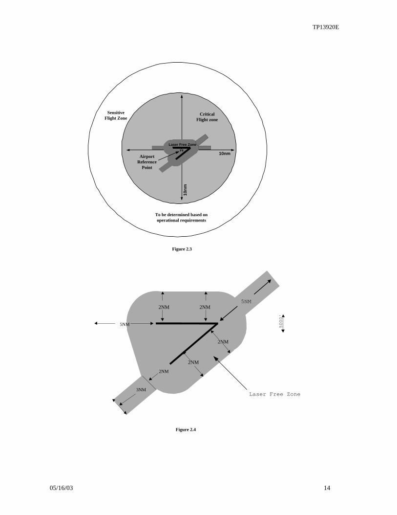
2.0: OUTDOOR LASER OPERATIONS 2.1 Airspace Restrictions
To protect aviation operations in the vicinity of airports, aerodromes, heliports and other areas, airspace shall be protected against hazardous beams. For non-visible lasers, the nominal ocular hazard distance (NOHD) value is the sole consideration. For visible lasers, in addition to the NOHD, visual disruption shall also be considered. Figures 2.2 – 2.5 define the zones established for aircraft in navigable airspace. Protective means (mitigation) shall be used to protect personnel and pilots when a visual interference level is exceeded. A backup system of mitigation is advisable in locations noted for heavy air traffic. Airspace shall be designated as sensitive flight zones, critical flight zones, and laser-free zones, where visible laser beams should not interfere with a pilot’s vision, even if the MPE is not exceeded. All other airspace is designated as normal flight zones. The beam from a visible laser shall not enter any zone, when the irradiance is greater than the corresponding visual interference level, unless adequate protective means are employed to prevent personnel exposure. Lasers with a beam irradiance less than the MPE, but exceeding the sensitive level or critical level may be operated in the sensitive zone or critical zone, respectively, if adequate means are used to prevent aircraft from entering the beam path.
3nm3nm 2nm
2nm
Laser Free Zone
FLIGHT ZONES
Critical Flight Zone
Figure 2.2
SensitiveFlightZone
Note: Size of SFZ to be determined by operational requirements
TP13920E
05/16/03 14
10nm
10nm
CriticalFlight zone
To be determined based onoperational requirements
Laser Free Zone
Figure 2.3
SensitiveFlight Zone
AirportReference
Point
2NM 2NM
2NM
2NM
5000'
5NM
5NM
2NM
3NMLaser Free Zone
Figure 2.4

TP13920E
05/16/03 15
2.2 Laser Zones
LASER FREE ZONE (LFZ): Airspace in the immediate proximity to the airport, up to and including 2,000 feet AGL, extending 2 nautical miles in all directions measured from the runway centerline, including a 3nm extension, 2,500 feet each side of the extended runway centerline of each useable runway surface. The level of laser light is restricted to a level that should not cause any visual disruption.
Parallel runways are measured from the runway centerline toward the outermost edges, plus that area between the runway centerlines. Within the area the level of laser light irradiance level shall not exceed 50nW/cm2 without some form of mitigation. This light level should not cause any visual disruption. (i.e. indistinguishable from background ambient light).
AIRSPACE FLIGHT ZONESELEVATION
AIRPORT REFERENCE POINT (ARP)
2
CRITICAL FLIGHT ZONE5µµµµ W/cm2
SENSITIVE FLIGHT ZONE100µµµµ W/cm2
TO BE DETERMINED 10nm10nm
3nm 3nm2nm 2nm
RUNWAY LENGTH VARIES PER AIRPORTAGL IS BASED ON PUBLISHED AIRPORT ELEVATION
2000
’
2000
’
8000
’
8000
’
TO
BE
DE
TE
RM
INE
D B
YL
OC
AL
AIR
POR
T O
PER
AT
ION
S
TO
BE
DE
TE
RM
INE
D B
YL
OC
AL
AIR
POR
T O
PER
AT
ION
S
TO BE DETERMINED
Figure 2.5
LASER FREE ZONE50nW/cm

TP13920E
05/16/03 16
CRITICAL FLIGHT ZONE (CFZ): That airspace within 10 nautical miles (NM) of the aerodrome ARP, from the surface up to and including 10,000 feet AGL. Adjust this zone as necessary to meet air traffic requirements. Within these areas the irradiance levels is not to exceed 5µW/cm² without some form of mitigation. This light level will not produce flashblindness or afterimage effects.
SENSITIVE FLIGHT ZONE (SFZ): Airspace outside the critical flight zone(s) identified as zone(s) that must be protected. This may or may not be contiguous or concentric with the CFZ. Within the area(s) the irradiance level is not to exceed 100µW/cm² without some form of mitigation. This light level provides protection, however, it may begin to produce flashblindness or afterimage effects of short duration. NORMAL FLIGHT ZONE (NFZ): All airspace not defined by the laser free, critical, or sensitive flight zones.
The amount of airspace affected by a laser operation varies with the laser system output power which is measured in watts or joules. Use the following maximum irradiance levels when evaluating laser operations:
a. Laser Free Zone equal to or less than 50nW/cm² b. Critical Flight Zone is equal to or less than 5µW/cm² c. Sensitive Flight Zone is equal to or less than 100µW/cm² d. Normal Flight Zone is equal to or less than the MPE for CW lasers or MPE for pulsed lasers.
NOTE: Items a, b, and c refer to visible laser emissions only.
If an irradiance value exceeds the limit shown, then some form of approved mitigation must be used to ensure aviation safety is preserved.

TP13920E
05/16/03 17
2.3 AERONAUTICAL ASSESSMENT PROCESS
The “Notice of Proposal” form shall be submitted to Transport Canada Headquarters, who will then forward copies to Health Canada and the appropriate Transport Canada Regional Office. The Transport Canada Regional Office, with the assistance of NAV CANADA, shall conduct aeronautical assessments, for the specific purpose of determining the potential effect of laser operations on the users of Canadian airspace, ensuring that mitigation action is taken to resolve any potentially hazardous effects to aviation.
Responsibilities of Proponents
1. The Proponent is to provide written notification (Notice of Proposal) to Transport Canada
Headquarters, normally 30 days in advance, of the proposed outdoor display. Whenever possible, the Proponent shall use the “Notice of Proposal” form (attached as Appendix A) to ensure that all appropriate information has been submitted.
2. The proponent is to liaise directly with the appropriate Transport Canada Regional Office
(Appendix C) to ensure that they are aware of the proposal and provide assistance as required to determine and mitigate any risks to aviation safety.
2.4 Determinations The appropriate Transport Canada Regional Office, with assistance from NAV CANADA, shall complete an aeronautical assessment and will respond to the Proponent in as timely a manner as possible. To ensure a satisfactory level of safety, any mitigation required shall be coordinated by Transport Canada directly with the Proponent. The completed assessment findings will be communicated to the Proponent. Objection or Non-objection findings may be given directly to the Proponent verbally, however for record purposes, the Transport Canada Regional Office will issue a Letter of Determination (LOD) to the Proponent.

TP13920E
05/16/03 18
AAeerroonnaauuttiiccaall AAsssseessssmmeenntt
Nav Canada Headquarters
Nav Canada Regional Safety Manager
Coordinate Nav Canada Regional participation in
A ti l A t
Health Canada Transport Canada Headquarters
Proponent
“Notice of Proposal”
Transport Canada Regional Office
Conduct aeronautical assessments in coordination with Nav Canada
Regional Office
Nav Canada Regional ATS
Provide operational input

TP13920E
05/16/03 19
3.0 OTHER OUTDOOR DIRECTED BRIGHT LIGHT OPERATIONS
3.1 PURPOSE
This chapter prescribes policy, standards and recommended practices for non laser outdoor directed bright light activities on users of Canadian airspace. 3.2 DEFINITIONS As used in this chapter the following terms are defined below:
a. Directed Bright Light (DBL): A lighting system other than laser light designed to promulgate into the navigable airspace. b. DBL Manufacturer: A term that refers to persons who manufactures directed bright light products. This includes those who are engaged in the business of design, assembly, or presentation of a DBL activity. c. DBL Operator: A knowledgeable person present during DBL operation who is responsible for ensuring compliance with applicable safety standards; monitoring the safe operation of a DBL operation; and can effect termination of the DBL promulgation in the event an unsafe condition becomes apparent.

Appendix A
05/16/03 20
3.3. POLICY
Existing searchlight technologies have been used for many years without adversely affecting aviation. Although a safety issue could arise if the light is carelessly operated in close proximity to an airport approach path, the light is not coherent light and therefore not inherently dangerous or injurious to the eye. Therefore, it is desirable to continue the policy of professional cooperation and coordination directly between the Operator and NAV CANADA. As new technologies emerge, Transport Canada will evaluate them and a determination will be made as to the aeronautical assessment requirements. 3.4 NOTICE OF OPERATIONS For those operations that are permanent installations or are not inherently dangerous to aviation, the Proponent shall file their equipment with Transport Canada Headquarters, by submitting a “Notice of Outdoor Directed Bright Light Equipment Parameters”. (see Appendix B), on a one-time basis. The Proponent need not submit another “Notice” unless there is a change in equipment or mode of operations. 3.5 AERONAUTICAL ASSESSMENT 3.3.4.1. Operators using existing Searchlight and Sky-Tracker technology, once their equipment is on file with Transport Canada, may coordinate their activities directly with the appropriate NAV CANADA Air Traffic or Flight Service facility as they have safely done in the past. A formal aeronautical assessment, as referred to in this document, is not required. The appropriate NAV CANADA Regional Office will coordinate NOTAM and Voice Advisory requirements.
Note: It is incumbent upon the directed bright light Operators to use professionalism in the use of their equipment. Any negligence on their part, which may have an adverse effect on aviation, will be summarily dealt with by Transport Canada.

Appendix A
05/16/03 21
NOTICE OF PROPOSAL TO CONDUCT OUTDOOR LASER
OPERATION(S)

Appendix A
05/16/03 22

Appendix A
05/16/03 23
NOTICE OF PROPOSAL TO CONDUCT OUTDOOR LASER OPERATION(S)
To: Transport Canada 7th Flr, Twr C, Place de Ville Ottawa, ON K1A 0N8 Attn: AARNA
From: (Applicant) Report date:
1. GENERAL INFORMATION Event or facility
Customer Site address
GEOGRAPHIC LOCATION Latitude ___ deg (° ) ___ min (‘) ___ sec (“) Longitude ___ deg (° ) ___ min (‘) ___ sec (“)
Ground elevation at site (above Mean Sea Level) Laser elevation above ground (if on buildings, etc.)
Determined by: ! GPS ! Map ! Other (specify)
DATE(S) AND TIME(S) OF LASER OPERATION Testing and alignment Operation
2. BRIEF DESCRIPTION OF OPERATION
3. ON-SITE OPERATION INFORMATION Operator(s) On-site phone #1 On-site phone #2
FDA CDRH LASER LIGHT SHOW VARIANCE (if applicable) Variance # Accession # Expiration date
BRIEF DESCRIPTION OF CONTROL MEASURES
4. ATTACHMENTS Number of laser configurations [fill out one copy of page 2 of this notice (“Laser Configurations”) for each configuration] List any additional attachments needed to evaluate this operation (could include maps, diagrams, and details of control measures)
5. DESIGNATED CONTACT PERSON (if further information is needed) Name Position
Phone Fax E-mail
STATEMENT OF ACCURACY To the best of my knowledge, the information provided in this Notice of Proposal is accurate and correct. Name (if different from contact person)
Position
Signature
Date

Appendix A
05/16/03 24

Appendix A
05/16/03 25
LASER CONFIGURATIONLASER CONFIGURATIONLASER CONFIGURATIONLASER CONFIGURATION
Fill out one copy of this form for each laser or laser configuration used at the Outdoor Laser Operations site 1. CONFIGURATION INFORMATION
Name of event/facility
This page is configuration number _____ of _____ Report date
Brief description of configuration
2. BEAM CHARACTERISTICS AND CALCULATIONS (check one Mode of Operation only, and fill in only that column) Mode of Operation ! SINGLE PULSE ! CONTINUOUS WAVE ! REPETITIVELY PULSED Laser Type (lasing medium)
Power Watts (W)
( not applicable) Maximum power Average power
Pulse Energy Joules (J)
(not applicable)
Pulse Width Seconds (s)
(not applicable)
Pulse Repetition Frequency Hertz (Hz)
(not applicable) (not applicable)
Beam Diameter @ 1/e points Centimeters (cm) (not mm)
Beam Divergence 1/e @ full angle Milliradians (mrad)
Wavelength(s) Nanometers (nm)
MAXIMUM PERMISSIBLE EXPOSURE (MPE) CALCULATIONS (will be used to calculate NOHD) MPE W/cm2
(not applicable)
MPE per pulse J/cm2
(not applicable)
VISUAL EFFECT CALCULATIONS (will be used only for visible lasers to calculate SZED, CZED and LFED) Pre-Corrected Power (PCP) Watts (W)
Pulse Energy (J) * 4 Maximum Power (from above) Average Power OR Pulse Energy (J) x PRF (Hz)
Visual Correction Factor (VCF) Enter “1.0” or use Table 5
Visually Corrected Power PCP x VCF
3. BEAM DIRECTION(S) Azimuth (degrees) ! True ! Magnetic Magnetic variation (degrees)
Minimum elevation angle (degrees, where horizontal = 0°) Maximum elevation angle (degrees)
4. DISTANCES CALCULATED FROM ABOVE DATA (Fill in all three columns for NOHD. If a visible laser, fill in all three columns for SZED, CZED, LFED)
SLANT RANGE (ft) HORIZONTAL DISTANCE (ft) VERTICAL DISTANCE (ft) NOMINAL OCULAR HAZARD DISTANCE NOHD (based on MPE) VISUAL EFFECT DISTANCES If the laser has no wavelengths in the visible range (400-700 nm), enter “N/A (non-visible laser)” in all blocks below. For visible lasers, if the calculated SZED, CZED, and/or LFED is less (shorter distance) than the NOHD, you must enter “Less than NOHD”. SZED (for 100 µW/cm2 level)
CZED (for 5 µW/cm2 level)
LFED (for 50 nW/cm2 level)
5. CALCULATION METHOD ! Commercial software (print product name) ! Other [describe method (spreadsheet, calculator, etc.)

Appendix A
05/16/03 26

Appendix A
05/16/03 27
Instructions for fillinInstructions for fillinInstructions for fillinInstructions for filling out Notice Of Proposal form (page 1)g out Notice Of Proposal form (page 1)g out Notice Of Proposal form (page 1)g out Notice Of Proposal form (page 1) The information in this form will be used to perform an aeronautical study to evaluate the safety of a proposed laser operation. Provide all information that the Office may need to perform the study. If additional details are necessary, list these in the “Attachments” section of this form. To: Send “Notice of Proposal” to Health Canada who will validate the calculations and forward the information to Transport Canada. Transport Canada, in coordination with NAV CANADA will do the aeronautical assessment. From: Enter the name, address, phone, fax, and E-mail of the applicant. This is the party primarily responsible for the laser safety of this operation. In some cases, the applicant is a manufacturer or a governmental agency (e.g., NASA), and the laser is located at a different site. In such a case, list the applicant here; the site location is filled in elsewhere in the form. Report date: This is the date the report is prepared or sent to Transport Canada. It is not the date of the laser operation. 1. GENERAL INFORMATION Event or facility: Enter the event name (for temporary shows) or the facility name (for permanent installations). Customer: If the laser user is different than the applicant, fill in the “Customer” section; if not, enter “Same as applicant”. Site address: Street address, city, state. GEOGRAPHIC LOCATION Latitude and Longitude: Be sure that latitude and longitude are specified in degrees, minutes and seconds. Some maps or devices may give this information in “Degrees.Decimal” form; this must be converted into degrees, minutes and seconds. Ground elevation at site: This is the elevation in feet above Mean Sea Level, at the show site. It can be found on a topographic map or other resource. Laser elevation above ground: If the laser is on a building or other elevated structure, enter the laser’s height in feet above the ground. Note: For lasers on aircraft or spacecraft, attach additional information on the flight locations and altitudes. DATE(S) AND TIME(S) OF LASER OPERATION Testing and alignment: Enter the date(s) and time(s) during which testing and alignment procedures will take place. Operation: Enter the date(s) and time(s) during which laser light will enter airspace. 2. BRIEF DESCRIPTION OF OPERATION This should be a general overview. Specific laser configurations at the operation are described in detail using the Laser Configuration form on page 2. If necessary, attach additional pages. 3. ON-SITE OPERATION INFORMATION Operator(s): List names and/or titles of operators. On-site phones: There should be at least one working, direct phone link to the operator, or equivalent way of quickly reaching the operator (e.g., phoning to a central station that reaches the operator via radio). Two telephone numbers are listed on the form, so one can be used as an alternate or backup.

Appendix A
05/16/03 28
FDA CDRH LASER LIGHT SHOW VARIANCE If the operation uses or is a “demonstration laser” (generally, a laser light show) and is therefore regulated by the Food and Drug Administration’s Center for Devices and Radiological Health, list the variance number, accession number and variance expiration date. BRIEF DESCRIPTION OF CONTROL MEASURES Describe the control measure(s) used to protect airspace; for example, termination on a building (where the beam path is not accessible by aircraft including helicopters), use of observers, use of radar and imaging equipment, physical methods of limiting the beam path, etc. The more that the operation relies on the control measures to ensure safety, the more detailed the description should be. 4. ATTACHMENTS Number of laser configurations: List how many “Laser Configurations” you are submitting with this proposal. If a particular setup operates with more than one laser, with different beam characteristics (power settings, pulse modes, divergence, etc.) or has multiple output devices (example: projector heads), then each should be analyzed as a separate Laser Configuration using the form on page 2. List additional attachments: You may need to add attachments such as maps, diagrams and details of control measures. Include whatever materials you feel are necessary to assist Transport Canada in sufficiently evaluating your proposal. 5. DESIGNATED CONTACT PERSON This is the person whom Transport Canada will contact if additional information is needed. This should be the person with the most knowledge about laser safety at this operation. However, it could also be a central contact person who interfaces between Transport Canada and the laser operation personnel. The Designated Contact Person must work for or represent the applicant listed in the “From:” area at the top of the form. STATEMENT OF ACCURACY The Designated Contact Person should sign the form. However, in some cases the responsibility for the accuracy of the information may rest with another person, such as a Laser Safety Officer who is not acting as the contact. Therefore, the person who has the authority to bind the applicant must sign the form.
Appendix A
05/16/03 29
Instructions for filling Instructions for filling Instructions for filling Instructions for filling out Laser Configuration form (page 2)out Laser Configuration form (page 2)out Laser Configuration form (page 2)out Laser Configuration form (page 2) A single outdoor operation may have a number of lasers or “laser configurations” – power settings, pulse modes, divergence, etc. On the Notice of Proposal form (page 1), in the first row of the Attachments table, enter the number of different laser configurations for the outdoor operation. Then, fill out one Laser Configuration form (page 2) for each different configuration to be analyzed. Alternative analysis: This form and accompanying tables must cover a wide variety of laser configurations. They are necessarily simplified, and they make conservative assumptions. Some laser configurations may warrant a more complex analysis. Any such alternative analysis should be based on the American National Standards Institute (ANSI) Z136 series of standards or other established methods. Both the methods and the calculations must be documented. 1. CONFIGURATION INFORMATION Brief description of configuration: Describe the beam projecting or directing system. Include description of site layout. Attach additional information if more space is required. 2. BEAM CHARACTERISTICS AND CALCULATIONS This section requires data about the laser beam’s characteristics. The data can be obtained from direct measurement, manufacturer specifications or specialized instruments. You can also derive data by making reasonable, conservative assumptions (for example, that a certain value makes the beam more hazardous than it would be in reality). All data should err on the side of safety. In borderline situations where data accuracy is crucial to compliance, provide additional data on measurement techniques, data sources and assumptions. Mode of operation: Determine the mode of operation for this configuration: Single Pulse, Continuous Wave, or Repetitively Pulsed. Put a check in the appropriate column. Fill out only that column for the remainder of this Beam Characteristics and Calculations section.
• Single Pulse: Lasers that produce a single pulse of energy with a pulse width < 0.25 seconds or a pulse repetition frequency < 1 Hz.
• Continuous Wave: A laser that produces a continuous (non-pulsed) output for a period > 0.25 seconds. • Repetitively Pulsed: Lasers that produce recurring pulses of energy at a frequency of 1 Hz or faster. Note on “repetitively pulsed” vs. scanning: “Repetitively pulsed” refers to lasers that naturally emit repetitive pulses, such as Q-switched lasers. The form and tables are not intended for analyzing pulses due to scanning the beam over a viewer or aircraft (examples: graphics or beam patterns used in laser displays; scanned patterns used for LIDAR). Pulses resulting from scanning are often extremely variable in pulse width and duration. Therefore, for a conservative analysis, assume the beam is static (non-scanned). Should you rely on scanning to be in compliance, you must 1) provide a more comprehensive analysis, documenting your methods and calculations, and 2) document and use scan-failure protection devices.
Laser Type: Enter the lasing medium, for example, “Argon”, “Nd-YAG”, “Copper-vapor”, “CO2”, etc. Power: If a continuous wave laser (Column 2), fill in the power in watts. If a repetitively pulsed laser (Column 3), fill in the average power in watts [energy per pulse (J) x pulse repetition frequency (Hz)]. For both types of power, this is the maximum power during the operation that enters airspace. For simplicity and safety you can enter a higher value, the maximum power of the laser; this ignores any additional losses in optical components in the beam path, before the beam enters airspace. Pulse Energy and Pulse Width: If a single pulse laser (Column 1) or repetitively pulsed laser (Column 3), fill in the pulse energy in joules and the pulse width in seconds. This is the maximum power that enters airspace. For simplicity and safety you can enter a higher value, the maximum pulse energy of the laser; this ignores any additional losses in optical components in the beam path, before the beam enters airspace. Beam Diameter: Provide the beam diameter using the 1/e peak-irradiance points. Note: Diameter is often expressed in millimeters. However, in this form you must enter the diameter in centimeters. (1 mm = 0.1 cm, 10 mm = 1 cm)

Appendix A
05/16/03 30
Beam Divergence: The beam divergence is the full angle given at the 1/e points. If you know the diameter or divergence measured at the 1/e2 points instead, multiply by 0.707 to convert to 1/e diameter or divergence. Note: Diameter and divergence measurements can be complex. You can use simplifying assumptions for safety. It is safer to assume the beam divergence is smaller than it really is. For example, as a beam travels from the laser through a laser show projector, the divergence generally increases. To be conservative (safer), use the smaller divergence of the beam at the laser, before it goes through the projector. This will assume the beam is tighter (and thus more hazardous) than it really is. Wavelength(s): Enter the wavelengths of laser light that enter airspace. If the laser emits multiple wavelengths, each wavelength will need to be analyzed separately to find their MPEs and NOHDs. In addition, for lasers emitting visible wavelengths, each wavelength can be analyzed separately to find the Visual Effect Distances (SZED, CZED, and LFED). This process is described in more detail in the Visual Effect Distances instructions below. In all cases of multiple-wavelength lasers, you must document your methods and calculations. If you do not analyze all wavelengths in full, then you must explicitly state your simplifying, conservative assumptions.
MAXIMUM PERMISSIBLE EXPOSURE CALCUATIONS MPE and MPE per pulse: Provide the Maximum Permissible Exposure (MPE) calculation results in the applicable block. This will be used later to determine the Nominal Ocular Hazard Distance (NOHD). The easiest way to find the MPE is to use Tables 1-4 as described immediately below. These tables provide a simple, conservative method. If you require less conservative levels, use the American National Standards Institute (ANSI) Z136 series of standards or other established methods. Both the methods and calculations must be documented.
• Single Pulse (Column 1): Use Table 1 to find the MPE. Fill in the “MPE per pulse” block in the Single Pulse column. • Continuous Wave (Column 2): Use Table 2 to find the MPE. Fill in the “MPE” block in the Continuous Wave column. • Repetitively Pulsed (Column 3): Lasers that produce recurring pulses of energy can produce an additional hazard above
that of a single pulse or continuous wave laser. The MPE is adjusted for repetitively pulsed lasers based on its pulse repetition frequency. The adjusted MPE is designated as MPEPRF. The MPEPRF can be determined using either the per-pulse energy or the average power. This document provides a simplified method for calculating the MPEPRF for average power with wavelengths in the visible and infrared region. (ANSI Z136 series can provide a less conservative value in some cases.) Although designated MPEPRF, the values should be placed in either the “MPE” or “MPE per pulse” blocks of the repetitively pulsed column. Following are the simplified methods for determining the MPEPRF for: 1. Ultraviolet wavelengths: Reference the American National Standards Institute ANSI Z136 series. 2. Visible wavelengths: Use Table 3 to determine the MPEPRF. Table 3 results have already applied the correction
factor to the cw MPE. Fill in the “MPE” block in the Repetitively Pulsed column. 3. Infrared wavelengths:
a. Use Table 2 to find the cw MPE b. Use Table 4 to find the infrared pulse repetition correction factor. c. Multiply the cw MPE times the infrared pulse repetition correction factor to give the MPEPRF. Fill in the “MPE”
block in the Repetitively Pulsed column.
Note for Repetitively Pulsed lasers: The simplified methods of Tables 2-4 use the Average Power to determine the MPE in W/cm2. It is possible with other methods to use the Pulse Energy to determine the MPE per pulse in J/cm2. Only one of the two MPEs is required.
VISUAL EFFECT CALCUATIONS (for visible lasers only) If the laser has no wavelengths in the visible range (400-700 nm), enter “N/A – non-visible laser” in these blocks and go to the next section (Beam Directions). For visible lasers, Transport Canada is concerned about beams that are eye-safe (below the MPE) but are bright enough to distract aircrews. Transport Canada has therefore adopted the standards for Sensitive, Critical and Laser-Free areas where aircraft should not be exposed to light above 100 µW/cm2, 5 µW/cm2, and 50 nW/cm2 respectively. Because apparent brightness varies with wavelength – green is more visible than red or blue – a visual correction factor can be applied if desired. This has the effect of allowing more power for red and blue beams than for green beams. For any visible laser, you must submit Visual Effect Calculations.

Appendix A
05/16/03 31
Pre-Corrected Power: The PCP is the power before applying any visual correction factor. The method used to determine the PCP depends on which type of laser you are using:
• Single Pulse (Column 1): Multiply the Pulse Energy (J) by 4, and enter in the form. Note: This technique averages the pulse’s energy over the 0.25 sec maximum pulse duration, and is a conservative approximation of the visual effect of a pulse. If you use less conservative calculations, you must document your methods and calculations.
• Continuous Wave (Column 2): The Pre-Corrected Power is the same as the maximum power of the laser. Enter the same value you previously filled out in the Power (W) block of the form.
• Repetitively Pulsed (Column 3): A) If you filled out the Power (W) block on the form, enter that value. B) If you filled out the Pulse Energy (J) block on the form, multiply that value times the Pulse Repetition Frequency (Hz) to determine the average power.
Visual Correction Factor and Visually Corrected Power: The VCF takes into account the beam’s apparent brightness, which varies depending on wavelength. Once you find the VCF, you can then determine the VCP. You have a choice of methods, depending on how precise you want to be:
1) For the simplest, most conservative analysis of a single- or multiple-wavelength beam: Assume there is no correction factor at all – the laser is at maximum apparent brightness (VCF of 1.0). In the Visual Correction Factor block of the form, enter “1.0 (assumed)”. In the Visually Corrected Power block, enter the same value you filled out for the Pre-Corrected Power.
2) For a single-wavelength beam: To find the Visual Correction Factor, use Table 5. To find the Visually Corrected Power, multiply the Visual Correction Factor by the Pre-Corrected Power. (An example calculation is provided at Table 5, footnote 1.)
3) For a beam with multiple wavelengths, choose one method: A) Make a simplifying, conservative assumption. Use Table 5 to determine which wavelength has the largest Visual Correction Factor (is the most visible). Enter this in the Visual Correction Factor block of the form. To find the Visually Corrected Power, multiply this Visual Correction Factor by the Pre-Corrected Power of the laser (all wavelengths). Note: You must attach data and calculations showing how you arrived at the Visually Corrected Power. B) Analyze each wavelength separately, then sum them. First, determine the Pre-Corrected Power for each wavelength. Next, use Table 5 to find the Visual Correction Factor for each wavelength. Multiply each wavelength’s Pre-Corrected Power by its Visual Correction Factor, to find the Visually Corrected Power (VCP) for that wavelength. Add all the VCPs together to determine the total VCP. Enter the total VCP in the “Visually Corrected Power” block of the form. (An example calculation is provided in Table 5, footnote 2.) Note: You must attach data and calculations showing how you arrived at the Visually Corrected Power.
3. BEAM DIRECTIONS Provide the pointing directions of the beam projections for this configuration. Azimuth: If the beam is moved horizontally during the operation, enter the movement range under “Azimuth”; for example, “20° to 50°”. Make sure you give the range going clockwise; otherwise your data will be interpreted as directing the beam everywhere but where you intend. Specify if azimuth is in true or magnetic readings. Magnetic variation: Provide the magnetic variation for the location if this is known (this must be done if you mark the “Magnetic” check box or if you are using a compass as part of your control measures). For some configurations, additional information about the beam direction may be needed. For example: lasers that are very widely separated at the Geographic Location listed on page 1, or a laser used on an aircraft or spacecraft which is moving and/or shoots downwards. If this additional information is useful for Transport Canada to evaluate the proposal, then attach the information to this form.

Appendix A
05/16/03 32
4. DISTANCES CALCULATED FROM ABOVE DATA There are four distances that are important in evaluating the safety of outdoor operations. Here are brief definitions:
• Nominal Ocular Hazard Distance (NOHD): The beam is an eye hazard (is above the MPE), from the laser source to this distance.
• Sensitive Zone Exposure Distance (SZED): The beam is bright enough to cause temporary vision impairment, from the source to this distance. Beyond this distance, the beam is 100µW/cm2 or less.
• Critical Zone Exposure Distance (CZED): The beam is bright enough to cause a distraction interfering with critical task performance, from the source to this distance. Beyond this distance, the beam is 5 µW/cm2 or less.
• Laser-Free Exposure Distance (LFED): Beyond this distance, the beam is 50 nW/cm2 or less – dim enough that it is not expected to cause a distraction.
For each of these four distances, it is important to know the distance directly along the beam (the Slant Range) as well as the ground covered (the Horizontal Distance) and the altitude (the Vertical Distance). The diagram shows these three distances.
Horizontal Distance
Vertical Distance
Slant Range
NOMINAL OCULAR HAZARD DISTANCE NOHD Slant Range: Use Equation 6.1 for Single Pulse, or for Repetitively Pulsed if you calculated the Pulse Energy and MPEPRF. Use Equation 6.2 for Continuous Wave, or for Repetitively Pulsed if you calculated the Average Power and MPE.
Equation 6.1 H
2NOHDMPE
Q 1366 SR×
= ×
φ
Where: SRNOHD = NOHD Slant Range in feet Q = Pulse Energy (J) φ = Beam Divergence (mrad) MPEH = MPE per pulse in J/cm2
1366 = Conversion factor used to convert centimeters into feet, and radians into milliradians
Equation 6.2 E
2NOHDMPE
1366 SR×
Φ= ×
φ
Where: SRNOHD = NOHD Slant Range in feet φ = Beam Divergence (mrad) Φ = Power (W) MPEE = MPE in W/cm2
1366 = Conversion factor used to convert centimeters into feet, and radians into milliradians Example: A 40-watt cw laser has a beam divergence of 1.5 milliradians
Given: φ = 1.5 mrad Φ = 40 W

Appendix A
05/16/03 33
MPEE = 0.00254 (2.54 mW/cm2, from Table 2) Solve Equation 6.2:
ft. 3,092 9560804 0.005715
00254.05.1
SR 546404013662NOHD ===×
= ×
NOHD Horizontal Distance is the distance along the ground. Note that the horizontal distance uses the minimum elevation angle. Calculate the horizontal distance using the equation:
HD = SRNOHD × cos(Minimum Elevation Angle) Where: HD = Horizontal distance along the ground. The units are the same as for the Slant Range. If SR is in feet, then HD will also be in feet. SRNOHD = NOHD Slant Range Minimum Elevation Angle = Data from “Minimum elevation angle” block on form. Example: The NOHD Slant Range is 1000 feet, and the beam is elevated at 30° above horizontal. The Horizontal Distance along the ground is 1000 x cos(30), or 866 feet.
NOHD Vertical Distance is the distance above the ground. Note that the vertical distance uses the maximum elevation angle. Calculate the vertical distance using the equation:
VD= SRNOHD× sin(Maximum Elevation Angle) Where:
VD = Vertical distance (altitude). The units are the same as for the Slant Range. If SR is in feet, then VD will also be in feet. SRNOHD = NOHD Slant Range Maximum Elevation Angle = Maximum elevation angle of laser beam as provided on form. Example: The NOHD Slant Range is 1000 feet, and the beam is elevated at 30° above horizontal. The Vertical Distance (altitude) is 1000 x sin(30), or 500 feet.
VISUAL EFFECT DISTANCES Fill in this section only if one or more of the laser wavelengths are visible (in the range 400-700 nm)
• If the laser is outside the visible range, enter “N/A – non-visible laser” in all SZED, CZED, and LFED blocks. • If the laser is visible, then perform the SZED, CZED, and LFED calculations below.
Important: For some visible pulsed lasers, the SZED, CZED, and LFED may be calculated to be less (shorter distance) than the NOHD. If this is the case, for safety reasons do not enter the distance numbers in the applicable block. Instead, you must enter that the distance is “Less than NOHD”. This is because in this case, the NOHD (eye-damage distance) would be the most important for calculating safety distances and airspace to be protected.
SZED Slant Range: Use the following equation:
Equation 6.3 VCPΦ×= 3700 SRSZEDφ
Where: SRSZED = SZED Slant Range φ = Beam Divergence (mrad) ΦVCP = Visually Corrected Power (from form) 3700 = Conversion factor used to convert centimeters into feet, and radians into milliradians

Appendix A
05/16/03 34
SZED Horizontal Distance: Use the following equation. For details, see the NOHD Horizontal Distance instructions above.
HD = SRSZED × cos(Minimum Elevation Angle)
SZED Vertical Distance: Use the following equation. For details see the NOHD Vertical Distance instructions above. VD= SRSZED× sin(Maximum Elevation Angle)
CZED Slant Range, Horizontal Distance and Vertical Distance: Multiply the SZED values above by 4.5. Example: If SZED Slant Range was 5,000 feet, HD was 866 feet, and VD was 500 feet, then the CZED SR is 22,500 feet, HD is 3,897 feet and VD is 2,250 feet. LFED Slant Range, Horizontal Distance and Vertical Distance: Multiply the SZED values above by 45. 5. CALCULATION METHOD List the method by which the calculations were performed. ________ Source note for equations: The equations above are derived from ANSI Z136.1 and have been re-expressed to a simpler form as follows: Beam divergence (φ) is entered in milliradians, making the first ANSI fraction 1000/φ instead of 1/φ. The radical (square root) sign is used instead of raising to a power of 0.5. Under the radical, the expression 4/π is reduced to 1.27, while beam diameter (a2) is not used since its contribution to the overall slant range distance is negligible. ANSI results are in cm; to convert to Transport Canada’s desired feet, a conversion factor of 0.0328 is used (1 cm = 0.0328 ft). There are now two numeric constants, 1000 (from the milliradians fraction) and 0.0328, which are multiplied into a single constant, 32.8, to give results in feet. For results in cm, use “1000” as the constant; for results in meters, use “10”. Note: The assumption that a constant can be used to derive the CZED and LFED from the previously-calculated SZED is valid only if atmospheric attenuation is ignored. Should you be relying on atmospheric attentuation for a safety factor, you must use a more detailed analysis which independently calculates these three Visual Effect Distances.

Appendix A
05/16/03 35
Table 1. Single Pulse Selected Maximum Permissible Exposure (MPE) Limits
Wavelength
(nm)
Exposure Duration
(sec)
MPE
(J/cm2)
Ultraviolet 180 to 400
10-9 to 10
Reference American National Institute Standard (ANSI) Z136 series
Visible 400 to 700 <10-9
10-9 to 18×10-6 18×10-6 to 10 0.25
Reference ANSI Z136 series 0.5×10⁻⁶ 1.8× t0.75×10-3
0.64×10⁻³ Infrared 700 to 1050 <10-9
10-9 to 18×10-6 18×10-6 to 10 0.25 10
Reference ANSI Z136 series 0.5×CA×10-6 1.8×CA× t0.75×10-3
0.64×CA×10-3
10×CA×10-3 1050 to 1400
<10-9 10-9 to 50×10-6 50×10-6 to 10 10
Reference ANSI Z136 series 5.0×CC×10-6 9×CC× t0.75×10-3 50×CC×10-3
1400 to 1500
<10-9 10-9 to 10-3 10-3 to 10 10
Reference ANSI Z136 series 0.1 0.56× t0.25 1.0
1500 to 1800
<10-9 10-9 to 10 10
Reference ANSI Z136 series 1.0 1.0
1800 to 2600
<10-9 10-9 to 10-3 10-3 to 10 10
Reference ANSI Z136 series 0.1 0.56× t0.25 1.0
2600 to 10,000 <10-9 10-9 to 10-7 10-7 to 10 10
Reference ANSI Z136 series 10×10-3 0.56× t0.25 1.0
To find CA: For wavelength = 700 to 1050nm, CA = 100.002 (wavelength-700)
Example 1: Laser wavelength is 850nm; CA = 100.002(850-700) = 100.002*150 = 100.3 = 1.995 Example 2: Laser wavelength is 933nm; CA = 100.002(933-700) = 100.002*233 = 100.466 = 2.924 To find CC: For wavelength = 1050 to 1150nm, CC = 1.0 For wavelength = 1150 to 1200nm, CC = 100.018 (wavelength-1150) For wavelength = 1200 to 1400nm, CC = 8.0 Example 3: Laser wavelength is 1175nm; Cc = 100.018(1175-1150) = 100.018*25 = 100.45 = 2.8 To find t: “t” is the pulse duration in seconds.

Appendix A
05/16/03 36
Table 2. CW Mode Maximum Permissible Exposure (MPE) Limits Values are for selected wavelengths for unintentional viewing.
Wavelength (nm)
MPE (W/cm2)
Ultraviolet 180 to 400 Reference American National
Standards Institute ANSI Z136 series
Visible
400 to 700 2.54x10⁻³
Infrared
700 to 1050 (100.002(wavelength - 700))(1.01x10⁻³)
1050 to 1150 5x10⁻³
1150 to 1200 (10 0.018(wavelength-1150))(5 x10⁻³)
1200 to 1400 4.0 x10⁻²
1400 to 10,000 0.1
Example 1: Laser wavelength is visible; MPE = 0.00254 W/cm2
Example 2: Laser wavelength is 850nm; MPE = (100.002(850 - 700))(1.01x10⁻³) = (100.002* 150)(0.00101) = (100.3) x 0.00101 = 1.995 x 0.00101 = 0.002 W/cm2
Example 3: Laser wavelength is 1175nm; MPE = (10 0.018(1175-1150))(5 x10⁻³) = (10 0.018* 25)(0.005) = (10 0.45) x 0.005 = 2.818 x 0.005 = 0.01409 W/cm2
“Unintentional viewing”: Exposure durations used for unintentional viewing of a cw exposure are 0.25 seconds or shorter for visible lasers, and 10 seconds or shorter for infrared lasers. (For visible light, it is assumed that within 0.25 seconds, the person will blink or will move to avoid the light. For infrared, it is assumed that the laser will not stay in the same spot for more than 10 seconds, due to normal body movement.) Source: ANSI Z136.1 Table 5 for CW Exposure.

Appendix A
05/16/03 37
Table 3. Maximum Permissible Exposure – Pulse Repetition Frequency (MPEPRF) Limits for Visible Lasers For unintentional viewing of repetitively pulsed visible (400-700nm) laser light with pulse width between 1ns and 18µs.
Pulse Repetition Frequency
(Hz)
MPEPRF
(W/cm2)
Pulse Repetition Frequency
(Hz)
MPEPRF
(W/cm2)
Pulse Repetition Frequency
(Hz)
MPEPRF
(W/cm2)
1 7.07×10-07 30 9.06×10-06 5000 4.20×10-04
2 1.19×10-06 40 1.12×10-05 10,000 7.07×10-04
3 1.61×10-06 50 1.33×10-05 15,000 9.58×10-04
4 2.00×10-06 75 1.80×10-05 20,000 1.19×10-03
5 2.36×10-06 100 2.24×10-05 25,000 1.41×10-03
6 2.71×10-06 150 3.03×10-05 30,000 1.61×10-03
7 3.04×10-06 200 3.76×10-05 40,000 2.00×10-03
8 3.36×10-06 250 4.45×10-05 50,000 2.36×10-03
9 3.67×10-06 500 7.48×10-05 55,000 2.54×10-03
10 3.98×10-06 1000 1.26×10-04 100,000 2.54×10-03
15 5.39×10-06 1500 1.70×10-04
20 6.69×10-06 2000 2.11×10-04
25 7.91×10-06 2500 2.50×10-04
If the laser’s pulse repetition frequency falls between two table entries, use the more conservative (smaller) value of the two resulting MPEPRF values. Note: This table for MPEPRF is based on repetitively pulsed lasers with a pulse width between 1ns and 18µs. These MPEPRF numbers can be used to estimate larger pulse widths, and will provide a conservative (safer) result. Not intended for scanning analysis: This table is intended for lasers that naturally emit repetitive pulses, such as Q-switched lasers. It is not intended for analyzing “scanned” pulses, caused by moving the beam quickly over a viewer or aircraft. (Examples: graphics or beam patterns used in laser displays, or scanned patterns used for atmospheric analysis.) Pulses resulting from scanning are often extremely variable in pulse width and duration, and thus require a more stringent analysis.

Appendix A
05/16/03 38
Table 4. Correction Factors (MPEpulsed / MPEcw) for Repetitively Pulsed Infrared Lasers Use to find MPEPRF of repetitively pulsed infrared (700-1400nm) laser light with pulse width between 1ns and 18µs.
Pulse Repetition Frequency
(Hz)
Correction Factor
For wavelengths 700 –1050 nm
Correction Factor
For wavelengths 1050-1400 nm
1 2.8×10⁻⁴ 5.5×10⁻⁴ 5 9.4×10⁻⁴ 1.8×10⁻³ 10 1.6×10⁻³ 3.1×10⁻³ 15 2.1×10⁻³ 4.2×10⁻³ 20 2.6×10⁻³ 5.2×10⁻³ 25 3.1×10⁻³ 6.2×10⁻³
50 5.3×10⁻³ 1.0×10⁻² 75 7.1×10⁻³ 1.4×10⁻²
100 9.0×10⁻³ 1.7×10⁻² 150 1.2×10⁻² 2.4×10⁻² 200 1.5×10⁻² 2.9×10⁻² 250 1.8×10⁻² 3.5×10⁻² 500 3.0×10⁻² 5.9×10⁻²
1,000 5.0×10⁻² 1.0×10⁻¹ 2,000 8.0×10⁻² 1.7×10⁻¹ 3,000 1.1×10⁻¹ 2.3×10⁻¹ 4,000 1.4×10⁻¹ 2.8×10⁻¹ 5,000 1.7×10⁻¹ 3.3×10⁻¹
10,000 2.8×10⁻¹ 5.6×10⁻¹ 15,000 3.8×10⁻¹ 7.5×10⁻¹ 20,000 4.7×10⁻¹ 9.3×10⁻¹ 21,000 4.8×10⁻¹ 9.7×10⁻¹ 22,000 5.0×10⁻¹ 1.00 * 23,000 5.2×10⁻¹ 1.00 24,000 5.4×10⁻¹ 1.00
25,000 5.5×10⁻¹ 1.00 30,000 6.3×10⁻¹ 1.00 40,000 7.9×10⁻¹ 1.00 50,000 9.3×10⁻¹ 1.00 55,000 1.00 * 1.00
* The MPE for lasers which operate at a PRF greater (faster) than 55,000 Hz for wavelengths 700-1050nm (or 22,000 Hz for wavelengths 1050-1400nm) is the same as for continuous wave lasers, so the correction factor is 1. To find the MPE for repetitively pulsed infrared lasers, multiply the CW Mode MPE by a correction factor from this table. If the laser’s pulse repetition frequency falls between two table entries, use the more conservative (smaller) value of the two resulting correction factors. Example: A laser operating at a pulse repetition frequency (PRF) of 12,000 Hz emits infrared light at 850nm. First, go to Table 2 and find the CW Mode MPE for the 850nm wavelength, which is 0.002 W/cm2 (see example 2 from Table 2). Next, from the table above determine which of the right two columns should be used; in this case, the column labeled “For wavelength 700-1050 nm”. The laser’s PRF of 12,000Hz falls between the 10,000 and 15,000 rows, so use the more conservative (smaller) value of the 10,000Hz PRF: 2.8 x 10⁻¹. The correction factor is thus 0.28. Multiply this by the CW Mode MPE found from Table 2 to get a MPEPRF of 0.28 x 0.002 W/cm2

Appendix A
05/16/03 39
= 0.00056 W/cm2 = 5.6 x 10⁻⁴ W/cm2.

Appendix A
05/16/03 40
Table 5. Visual Correction Factor for Visible Lasers Use for visible lasers only (400-700 nm).
Laser Wavelength
(nm)
Visual Correction
Factor (VCF)
400 410 420 430 440
450 460 470 480 490
500 510 520 530 540
550 555 560 570 580 590
600 610 620 630 640
650 660 670 680 690 700
4.0 x 10⁻⁴ 1.2 x 10⁻³ 4.0 x 10⁻³
1.16 x 10⁻² 2.30 x 10⁻²
3.80 x 10⁻² 5.99 x 10⁻² 9.09 x 10⁻²
1.391 x 10⁻¹ 2.079 x 10⁻¹
3.226 x 10⁻¹ 5.025 x 10⁻¹ 7.092 x 10⁻¹ 8.621 x 10⁻¹ 9.524 x 10⁻¹
9.901 x 10⁻¹
1.0 x 100 9.901 x 10⁻¹ 9.524 x 10⁻¹ 8.696 x 10⁻¹ 7.576 x 10⁻¹
6.329 x 10⁻¹ 5.025 x 10⁻¹ 3.817 x 10⁻¹ 2.653 x 10⁻¹ 1.751 x 10⁻¹
1.070 x 10⁻¹ 6.10 x 10⁻² 3.21 x 10⁻² 1.70 x 10⁻² 8.2 x 10⁻³ 4.1 x 10⁻³
(VCF=1)
To find the Visually Corrected Power (VCP) for a specified wavelength, multiply the Visual Correction Factor (VCF) for the wavelength (from the table above) by the Average Power. If the laser’s wavelength falls between two table entries, use the more conservative (larger) value of the two resulting VCFs. Example 1: A frequency-doubled YAG laser emits 10 watts of 532nm continuous wave light. From the table, 532 is between 530 and 540; use the more conservative (larger) Visual Correction Factor of 540nm: 9.524 x 10⁻¹. Multiply the VCF of 0.9524 by the Average Power of 10 watts, to obtain the Visually Corrected Power of 9.524 watts. Example 2: An 18-watt argon laser emits 10 watts of 514nm light, and 8 watts of 488nm light, both continuous wave. Calculate each wavelength separately, then add the resulting Visually Corrected Powers together. 10 watts at 514nm: From the table, 514 is between 510 and 520; use the more conservative (larger) VCF of 520nm: 7.092 x 10⁻¹. Multiply the VCF of 0.7092 by the Average Power of 10 watts, to obtain the Visually Corrected Power of 7.092 watts. 8 watts at 488nm: From the table, 488 is between 480 and 490; use the more conservative (larger) VCF of 490nm: 2.079 x 10⁻¹. Multiply the VCF of 0.2079 by the Average Power of 8 watts, to obtain the Visually Corrected Power of 1.6632 watts. Finally, add the two VCPs together: 7.092 + 1.6632 = 8.7552. The 18-watt laser in this example has a Visually Corrected Power of only 8.7552 watts. Note that the 10-watt YAG in Example 1 appears brighter to the eye (9.5 WVCP) than an 18-watt argon (8.8 WVCP).

Appendix A
05/16/03 41
Source: The Visual Correction Factor (CF) used in this table is the CIE normalized efficiency photopic visual function curve for a standard observer. The luminance (lm• cm-²) is the measured irradiance multiplied by CF and 683. The effective irradiance is the actual (measured) irradiance multiplied by CF. The effective irradiance (W⋅ cm-2) multiplied by 683 lm⋅ W-1 is the illuminance (lm⋅ cm-2). The term “Visually Corrected Power” divided by the area of the laser beam is the “effective irradiance”, as used in this document.

Appendix B
05/16/03 42
NOTICE OF OUTDOOR DIRECTED BRIGHT LIGHT EQUIPMENT PARAMETERS

Appendix B
05/16/03 43

Appendix B
05/16/03 44
NOTICE OF OUTDOOR DIRECTED BRIGHT LIGHT EQUIPMENT PARAMETERS
To: Transport Canada 7th Flr, Twr C, Place de Ville Ottawa, ON K1A 0N8 Attn: AARNA
From: Applicant Name: Tel:
Date:
1. GENERAL INFORMATION Company Name: Address: Tel:
Fax: E-Mail:
Equipment Type ( Light Source):
Electrical Power (Watts) : Optical Power (candela):
2. BRIEF DESCRIPTION OF OPERATION
( Projection / Rotation Pattern / Max Tilt Angle / RPM )
3. DESIGNATED CONTACT PERSON (if further information is needed) Name: Title:
Phone: Fax: E-mail:
STATEMENT OF ACCURACY To the best of my knowledge, the information provided in this Notice of Proposal is accurate and correct. Name (if different from contact person):
Title:
Signature:
Date:

Appendix E
05/16/03 45

Appendix E
05/16/03 46
TRANSPORT CANADA REGIONS AND
LIST OF CONTACTS

Appendix E
05/16/03 47

Appendix E
05/16/03 48

Appendix E
05/16/03 49

Appendix E
05/16/03 50
LIST OF CONTACTS
TRANSPORT CANADA
Head Office Aeronautical Information Services & Airspace Standards 7th Floor, Tower “C” Place de Ville 330 Sparks St Ottawa, ON K1A 0N8
Alain Piche Tel: (613) 990-2090 Email: [email protected] Ron Carter Tel: (613) 998-9855 Email: [email protected]
Fax: (613) 998-7416

Appendix E
05/16/03 51
Regional Offices
Pacific ANS & Airspace
Transport Canada
660-800 Burrard
Vancouver, BC V6Z 2J8
Geoff Graham Tel: (604) 666-5490
Email: [email protected]
Bud Spencer Tel: (604) 666-1090
Email: [email protected]
Fax: (604) 666-1175
Prairie and Northern Edmonton
ANS & Airspace
Transport Canada
1100-9700 Jasper Ave
Edmonton, AB T5J 4E6
Mike Barbeau Tel: (780) 495-2505
Email: [email protected]
John Burdett Tel: (780) 495-6252
Email: [email protected]
Fax: (780) 495-3968

Appendix E
05/16/03 52
Winnipeg
ANS & Airspace
Transport Canada
P.O. Box 8550
344 Edmonton St
Winnipeg, MB R3C 0P6
Bruce McMillan Tel: (204) 983-5290
Email: [email protected]
Fax: (204) 983-0281
Ontario ANS & Airspace
Transport Canada
4900 Young St, Suite 300
North York, ON M2N 6A5
Ron King Tel: (416) 952-3598
Email: [email protected]
Clifford Frank Tel: (416) 952-0243
Email: [email protected]
Greg Cross Tel: (416) 916) 952-0022
Email: [email protected]
Fax: (416) 952-0050

Appendix E
05/16/03 53
Quebec ANS & Airspace
Transport Canada
700, Leigh Capreol
Dorval, QB H4Y 1G7
Monique Genest Tel: (514) 633-3514
Email: [email protected]
Pierre Forget Tel: (514) 633-2980
Email: [email protected]
Fax: (514) 633-3052
Atlantic ANS & Airspace
Transport Canada
PO Box 42 95 Foundry St
Moncton, NB E1C 8K6
Reg Lynch Tel: (506) 851-7586
Email: [email protected]
Fax: (506) 851-3022

Appendix E
05/16/03 54
NAV CANADA
Head Office
Manager
ANS Planning and Service Design
77 Metcalfe St
Ottawa, ON K1P 5L6
Jeff MacDonald Tel: (613) 563-3356
Email: macdjef@NAV CANADA.ca
Fax: (613)563-5602
HEALTH CANADA Radiation Protection Bureau 775 Brookfield Road, 6301B Ottawa, ON K1A 1C1 Michelle Cybulski Tel: (613) 941-3957 Email: [email protected] Yvon Deslauriers Tel: (613) 954-0303 Email: [email protected]
Fax: (613) 941-1734