USE OF MEMS ACCELEROMETERS/INCLINOMETERS AS A GEOTECHNICAL ... · USE OF MEMS...
12
Acta Geodyn. Geomater., Vol. 11, No. 4 (176), 337–349, 2014 DOI: 10.13168/AGG.2014.0015 journal homepage: http://www.irsm.cas.cz/acta ORIGINAL PAPER USE OF MEMS ACCELEROMETERS/INCLINOMETERS AS A GEOTECHNICAL MONITORING METHOD FOR GROUND SUBSIDENCE Cheng LI 1) *, Tomas M. FERNANDEZ-STEEGER 1) , Jó Ágila Bitsch LINK 2) , Matthias MAY 2) and Rafig AZZAM 2) 1) Department of Engineering Geology and Hydrogeology, RWTH Aachen University, Lochnerstr 4-20, Aachen, Germany 2) Chair of Communication and Distributed Systems, RWTH Aachen University, Ahornstr 55, Aachen, Germany *Corresponding author‘s e-mail: [email protected] ABSTRACT Accelerometer and inclinometer are inertial sensors capable of measuring corresponding magnitude of Earth gravitational field along the direction of each axis. By means of rotation matrices related to inertial navigation methods, the output values of a three-dimensional accelerometer or a two-dimensional inclinometer can be transformed and processed into the azimuth and dip angle of the monitored target. With the rapid growth in development and cost reduction of Micro Electro Mechanical Systems (MEMS) and Wireless Sensor Network (WSN) in recent years, the engineers are able to carry out real-time wireless geotechnical monitoring during construction. In this paper, we set up a one-day measurement implemented by a self- developed wireless MEMS monitoring system on the surface in the construction site of South Hongmei Road super high way tunnel in Shanghai, by making use of rotation matrices in specific ways, the raw data are processed to expressions of three-dimensional normal vectors that represent the change of the ground. After unifying the vectors in the same coordinate system, we conduct a brief ground settlement analysis by means of an evaluation of the dip angles in the cross section and the azimuths of the sensor nodes. ARTICLE INFO Article history: Received 16 April 2014 Accepted 28 August 2014 Available online 8 October 2014 Keywords: Accelerometer Inclinometer Rotation matrices Ground subsidence type in geotechnical monitoring system, accelerometer measures not only dynamic acceleration forces caused by vibrating or moving, but also static forces like the constant gravity pointing to the Earth, which principally agrees with the inclinometer. As the output of an accelerometer or inclinometer represents the weight of the Earth gravitational field along the axis, the tilting angle of the axis with respect to the horizontal plane is simple to obtain via a sine function (Fig. 1). 1. INTRODUCTION Due to the fast development of Micro Electro Mechanical Systems (MEMS) and the reduction of sensor cost, size and energy consumption in the last two decades, Wireless Sensor Networks (WSN) integrated with MEMS sensors have progressively been adopted into wide areas such as target tracking (Bitsch Link et al., 2010a), health monitoring (Wang and Balasingham, 2010) and environmental monitoring (Martinez et al., 2006; Cho et al., 2008). Besides, there has been an increasing concern in wireless monitoring that are embedded with MEMS during geotechnical activity (Lynch and Loh, 2006); applications have covered structural health monitoring of underground coal mines (Li and Liu, 2009), bridges (Kim et al., 2007), railways and rail vehicles (Nejikovsky and Keller, 2000; Shafiullah et al., 2007) and pipelines (Stoianov et al., 2007) construction. Aiming to enable a high-qualified, low-cost real-time surveillance system during geotechnical processes, the Department of Engineering Geology and Hydro- geology and Department of Communication and Distributed Systems at RWTH Aachen University have collaborated to develop a MEMS embedded wireless monitoring system called “X-SLEWS”, which include a three-axis accelerometer and a two- axis inclinometer in each mote and is capable of measuring and sending tilting information with a set- table frequency to the base station via a wireless network (May et al., 2013). As a broadly used sensor Fig. 1 The measurement of the accelerometer. The accelero- meter measures the value of g , which represents for the weight of the Earth’s gravitational field g in the axial direction on the sensor board. The tilting angle of the axis with respect to the horizontal plane can be calculated via an inverse trigonometric function: g arcsin g .
Transcript of USE OF MEMS ACCELEROMETERS/INCLINOMETERS AS A GEOTECHNICAL ... · USE OF MEMS...
Acta Geodyn. Geomater., Vol. 11, No. 4 (176), 337–349, 2014
DOI: 10.13168/AGG.2014.0015
journal homepage: http://www.irsm.cas.cz/acta
ORIGINAL PAPER
USE OF MEMS ACCELEROMETERS/INCLINOMETERS AS A GEOTECHNICAL MONITORING METHOD FOR GROUND SUBSIDENCE
Cheng LI 1)*, Tomas M. FERNANDEZ-STEEGER 1), Jó Ágila Bitsch LINK 2), Matthias MAY 2) and Rafig AZZAM 2)
1) Department of Engineering Geology and Hydrogeology, RWTH Aachen University, Lochnerstr 4-20, Aachen, Germany
2) Chair of Communication and Distributed Systems, RWTH Aachen University, Ahornstr 55, Aachen, Germany
*Corresponding author‘s e-mail: [email protected]
ABSTRACT
Accelerometer and inclinometer are inertial sensors capable of measuring corresponding magnitude of Earth gravitational field along the direction of each axis. By means of rotation matrices related to inertial navigation methods, the output values of a three-dimensional accelerometer or a two-dimensional inclinometer can be transformed and processed into the azimuth and dip angle of the monitored target. With the rapid growth in development and costreduction of Micro Electro Mechanical Systems (MEMS) and Wireless Sensor Network (WSN)in recent years, the engineers are able to carry out real-time wireless geotechnical monitoringduring construction. In this paper, we set up a one-day measurement implemented by a self-developed wireless MEMS monitoring system on the surface in the construction site of SouthHongmei Road super high way tunnel in Shanghai, by making use of rotation matrices inspecific ways, the raw data are processed to expressions of three-dimensional normal vectors that represent the change of the ground. After unifying the vectors in the same coordinate system, we conduct a brief ground settlement analysis by means of an evaluation of the dip angles in thecross section and the azimuths of the sensor nodes.
ARTICLE INFO
Article history:
Received 16 April 2014 Accepted 28 August 2014 Available online 8 October 2014
Keywords: Accelerometer Inclinometer Rotation matrices Ground subsidence
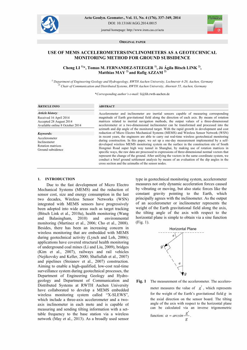
type in geotechnical monitoring system, accelerometer measures not only dynamic acceleration forces caused by vibrating or moving, but also static forces like the constant gravity pointing to the Earth, which principally agrees with the inclinometer. As the output of an accelerometer or inclinometer represents the weight of the Earth gravitational field along the axis,the tilting angle of the axis with respect to the horizontal plane is simple to obtain via a sine function (Fig. 1).
1. INTRODUCTION
Due to the fast development of Micro Electro Mechanical Systems (MEMS) and the reduction of sensor cost, size and energy consumption in the last two decades, Wireless Sensor Networks (WSN) integrated with MEMS sensors have progressively been adopted into wide areas such as target tracking (Bitsch Link et al., 2010a), health monitoring (Wang and Balasingham, 2010) and environmental monitoring (Martinez et al., 2006; Cho et al., 2008). Besides, there has been an increasing concern in wireless monitoring that are embedded with MEMS during geotechnical activity (Lynch and Loh, 2006);applications have covered structural health monitoring of underground coal mines (Li and Liu, 2009), bridges (Kim et al., 2007), railways and rail vehicles(Nejikovsky and Keller, 2000; Shafiullah et al., 2007) and pipelines (Stoianov et al., 2007) construction. Aiming to enable a high-qualified, low-cost real-time surveillance system during geotechnical processes, the Department of Engineering Geology and Hydro-geology and Department of Communication and Distributed Systems at RWTH Aachen University have collaborated to develop a MEMS embedded wireless monitoring system called “X-SLEWS”, which include a three-axis accelerometer and a two-axis inclinometer in each mote and is capable of measuring and sending tilting information with a set-table frequency to the base station via a wireless network (May et al., 2013). As a broadly used sensor
Fig. 1 The measurement of the accelerometer. The accelero-
meter measures the value of g , which represents
for the weight of the Earth’s gravitational field g in
the axial direction on the sensor board. The tilting angle of the axis with respect to the horizontal plane can be calculated via an inverse trigonometric
function: g
arcsing
.
Ch. Li et al.
338
Road super high way tunnel in Shanghai, by means of collecting data from three wireless sensor nodes equipped with MEMS accelerometers and inclino-meters, in order to detect ground deformation caused by underground excavation. In this paper, we provide an indirect subsidence measuring methodology, which considers the change of inclination at the surveying point rather than the absolute displacement. The rest of this paper is organized as follows: First we give a brief description of the wireless sensor network and field deployment; and then we explain the data processing methodology of how to retrieve the path of the normal vector of the sensor board over time;finally, we perform a deformation analysis based on the normal vector we deduced along with the ideas about future work regarding this method.
2. SENSOR NETWORK
The X-SLEWS is a joint project under the collaboration of the Department of Engineering Geology and Hydrogeology and Department of Communication and Distributed Systems at RWTH Aachen University intending to provide a flexible platform for wireless sensor networks (May et al., 2013) (Fig. 2). The idea is generalized from the project of Sensor-based Landslide Early Warning System (SLEWS) (Fernandez-Steeger et al., 2009), which has also been applied to monitor ground
The X-SLEWS is currently designed for surface surveillance, which lead us to find the possibility of measuring ground deformation during underground excavation as a suitable deployment case. With the increasing population density in urban space, subsurface structures like tunnels have become an effective means to comply with the metropolitan requirement. Underground excavation accompanied with ground stress redistribution can cause damage to surface or subsurface structures, thus structural health monitoring is taken necessarily during construction process to prevent damages or accidents. In the aspect of land subsidence monitoring, there are varieties of methods available to measure the settlement, which include vertical extensometers, geodetic survey using Global Positioning System (GPS) or conventional leveling methods, and Interferometric Synthetic Aperture Radar (InSAR); some of the related applications are given here (Bitelli et al., 2000;Buckley et al., 2003; Tomás et al., 2010). Thanks to the booming market of smartphones and video game consoles (Lane et al., 2010; Maenaka, 2008), non-mechanical experts have progressively gained the experience of the application of accelerometers or inclinometers. Aiming at integrating the MEMS embedded X-SLEWS into geotechnical monitoring activity, we conducted a one-day measurement on the ground at the construction site of the South Hongmei
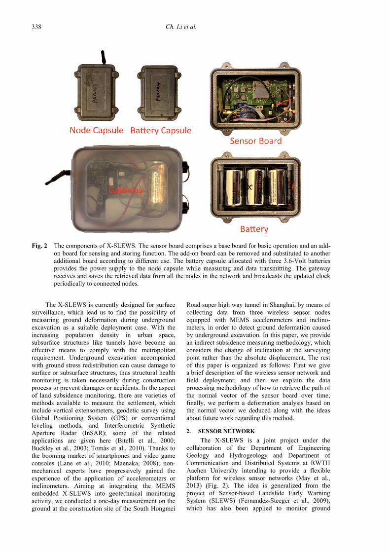
Fig. 2 The components of X-SLEWS. The sensor board comprises a base board for basic operation and an add-on board for sensing and storing function. The add-on board can be removed and substituted to another additional board according to different use. The battery capsule allocated with three 3.6-Volt batteries provides the power supply to the node capsule while measuring and data transmitting. The gateway receives and saves the retrieved data from all the nodes in the network and broadcasts the updated clock periodically to connected nodes.
USE OF MEMS ACCELEROMETERS/INCLINOMETERS AS A GEOTECHNICAL MONITORING … .
339
subsidence in an open pit mine (Fernandez-Steeger et al., 2013) besides landslide surveillance. Instead of usingprevious SLEWS nodes provided by ScatterWeb as a black box, we implemented the popular open-source operating system TinyOS that is targeted at sensor network applications on the X-SLEWS platform.
2.1. BRIEF INTRODUCTION TO HARDWARE
The hardware layout of the sensor node is divided into two components: the base board that contains theparts required for basic operation of the node, and the add-on board that is deployed with sensors and offers additional functions. Specifically, the base board includes the microcontroller, the power supply circuitry and a socket for the radio module; the add-on board is allocated with a SD card socket for optional data storage as well as a 3-axis accelerometer and two orthogonal 1-axis inclinometers for geotechnical use. Both of the sensors are high performed MEMS sensors with a sensitivity of 0.0637°/count for the accelerometer and 0.00179°/countfor the inclinometer. The XBee radio module family is chosen as the radio component based on its variety of radio frequencies and promising performance for long-distance radio transmission during a previous project (Bitsch Link et al., 2010b). The sensor node is powered by three 3.6 volt batteries, and the microcontroller or peripheral components could be provided with an appropriate supply voltage via a voltage regulator. All the sensed data will be stored into the SD card on the add-on board as well as be transmitted to the network’s gateway - also the base station, which consists of a node and a Raspberry Pi and periodically updates and broadcasts the clock to all connected nodes. This design ensures no loss of data, even when the network istemporally weak or disconnected, data of each sensor node can be read later from the SD card. 2.2. DATA FORMAT
The data received at the base station is stored in a plain text log file and formatted as:
2013-01-15T19:11:00.027989+0800 > $1358239557|101|1|10@1358230555|ACC|1|-82|988|80
2013-01-15T19:11:00.043215+0800 > $1358239557|101|1|10@1358230555|BATT|4028
2013-01-15T19:11:00.055838+0800 > $1358239557|101|1|10@1358230555|INC|-17156|-59718
Which can be separated by the delimiters “>”, “|” and “@” and read from left to right as the timestamp from the Linux-based Raspberry Pi, the timestamp of the receiving time of the data from the sensor node that belongs to the base station, the node ID of the sensor node that creates the message, the node ID of the first recipient in the path to the base station (“1” represents for the base station), 10 times of the estimated number of required transmission during delivery, the gathering time of the data according to the sensor node, and the sensed data with respect to different categories. Concretely, the acceleration data of 3 axes of accelerometer are given behindthe abbreviation “ACC”, following with a temperature measured by an embedded thermometer; the number behind “BATT” shows the current voltage from the external power supply; “INC” leads a spontaneous data setfrom the two orthogonal inclinometers. To ensure the digital accuracy after transmission, the units of the data from the accelerometer, the battery and the inclinometer are chosen as 2mm s ,mV and 2m s .
For the described experiment, the X-SLEWS network was deployed on the surface above underground excavation for a tunnel in Shanghai for one day. The data collected were processed step by step according to the methodology that is going to be discussed in the following.
3. DATA PROCESSING
In the case of geotechnical monitoring such as ground subsidence, we require the inclination angle and the azimuth of the detected tilting surface, the values of which can be expressed from the normal vector of the sensor board plane. To obtain the normal vector rather than three tilt angles along sensor axes, we have implemented the rotation matrices that refer to inertial navigation method into the processing of data (Jekeli, 2001). The method is presented in four sub-steps as below.
3.1. ROTATION MATRICES AND THE EXPRESSION OF G’
Inertial Navigation System (INS) is a navigation aid that combines a computer and sensors to successively calculate the position, orientation and velocity of a moving object without the need for external references(Jekeli, 2001), which is commonly used by vehicles like ships, aircrafts, and guided missiles. The use of rotation matrices is the key to realize coordinate transformation, which helps the vehicle to trace targets from its ownnavigation system and is much significant during relative movement. To start with, the Euler Orientation Cosine Matrix is briefly introduced here.
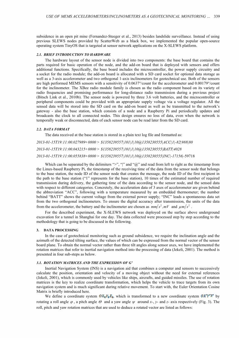
We define a coordinate system , which is transformed to a new coordinate system byrotating a roll angle , a pitch angle and a yaw angle around x-, y- and z- axis respectively (Fig. 3). The
roll, pitch and yaw rotation matrices that are used to deduce a rotated vector are listed as follows:
Ch. Li et al.
340
Fig. 3 Coordinate system transforming through the order of X Y Z . The initial coordinate system 0 0 00X Y Z
(a) is transformed to 0X Y Z under a rotation by angles in roll (b), in pitch (c) and in yaw (d)
around the x-, y- and z-axis respectively.
There are 6 possible orders for the rotation of the coordinate system and principally they are equally valid. Following different rotation orders, the expressions of gravitational vector in the new coordinate system are correspondingly distinctive.However, the roll and pitch can only be solved by the orders of Z-Y-X or Z-X-Y since a spatial vector has two degrees of freedom (Pedley, 2013). Taking the Z-Y-X order for instance, after being rotated successively around z-, y- and x-axis, the rotated
vector of Earth gravitational field 0 0 1, , can be
expressed as:
1 0 0
0
0xR cos sin
sin cos
1)
0
0 1 0
0y
cos sin
R
sin cos
(2)
0
0
0 0 1z
cos sin
R sin cos
(3)
USE OF MEMS ACCELEROMETERS/INCLINOMETERS AS A GEOTECHNICAL MONITORING … .
341
0
0
1xyz x y z
sin
g R R R cos sin
cos cos
(4)
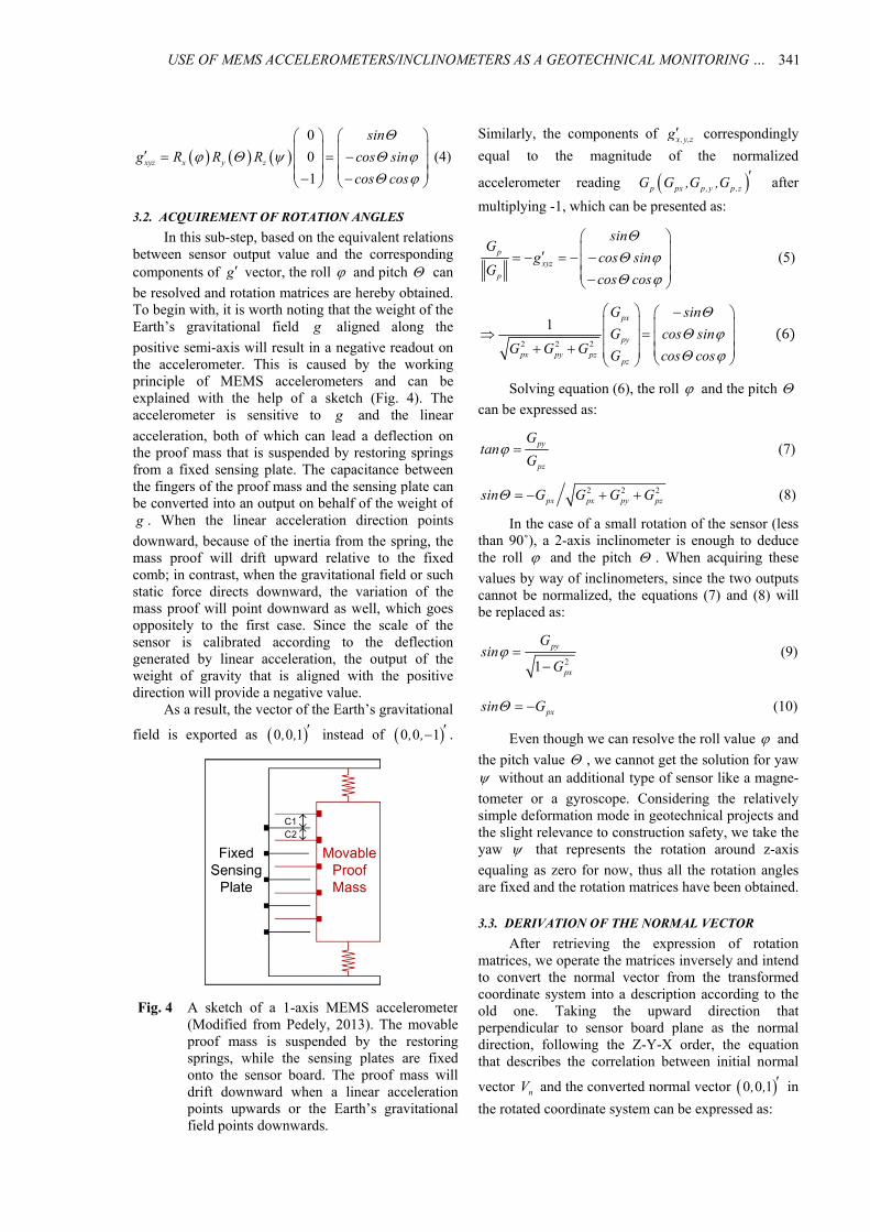
3.2. ACQUIREMENT OF ROTATION ANGLES
In this sub-step, based on the equivalent relations between sensor output value and the corresponding components of g vector, the roll and pitch can
be resolved and rotation matrices are hereby obtained.To begin with, it is worth noting that the weight of the Earth’s gravitational field g aligned along the
positive semi-axis will result in a negative readout on the accelerometer. This is caused by the working principle of MEMS accelerometers and can be explained with the help of a sketch (Fig. 4). The accelerometer is sensitive to g and the linear
acceleration, both of which can lead a deflection on the proof mass that is suspended by restoring springs from a fixed sensing plate. The capacitance between the fingers of the proof mass and the sensing plate can be converted into an output on behalf of the weight of g . When the linear acceleration direction points
downward, because of the inertia from the spring, the mass proof will drift upward relative to the fixed comb; in contrast, when the gravitational field or such static force directs downward, the variation of the mass proof will point downward as well, which goesoppositely to the first case. Since the scale of the sensor is calibrated according to the deflectiongenerated by linear acceleration, the output of the weight of gravity that is aligned with the positive direction will provide a negative value.
As a result, the vector of the Earth’s gravitational
field is exported as 0 0 1, , instead of 0 0 1, , .
Fig. 4 A sketch of a 1-axis MEMS accelerometer (Modified from Pedely, 2013). The movable proof mass is suspended by the restoringsprings, while the sensing plates are fixedonto the sensor board. The proof mass willdrift downward when a linear accelerationpoints upwards or the Earth’s gravitational field points downwards.
Similarly, the components of x ,y,zg correspondingly
equal to the magnitude of the normalized
accelerometer reading p px p ,y p ,zG G ,G ,G after
multiplying -1, which can be presented as:
pxyz
p
sinG
g cos sinG
cos cos
(5)
2 2 2
1px
py
px py pzpz
G sin
G cos sinG G G G cos cos
6
Solving equation (6), the roll and the pitch can be expressed as:
py
pz
Gtan
G (7)
2 2 2px px py pzsin G G G G (8)
In the case of a small rotation of the sensor (less than 90˚), a 2-axis inclinometer is enough to deducethe roll and the pitch . When acquiring these
values by way of inclinometers, since the two outputscannot be normalized, the equations (7) and (8) willbe replaced as:
21
py
px
Gsin
G
(9)
pxsin G (10)
Even though we can resolve the roll value and
the pitch value , we cannot get the solution for yaw without an additional type of sensor like a magne-
tometer or a gyroscope. Considering the relatively simple deformation mode in geotechnical projects and the slight relevance to construction safety, we take the yaw that represents the rotation around z-axis
equaling as zero for now, thus all the rotation angles are fixed and the rotation matrices have been obtained.
3.3. DERIVATION OF THE NORMAL VECTOR
After retrieving the expression of rotation matrices, we operate the matrices inversely and intendto convert the normal vector from the transformed coordinate system into a description according to the old one. Taking the upward direction that perpendicular to sensor board plane as the normal direction, following the Z-Y-X order, the equationthat describes the correlation between initial normal
vector nV and the converted normal vector 0 0 1, , in
the rotated coordinate system can be expressed as:
Ch. Li et al.
342
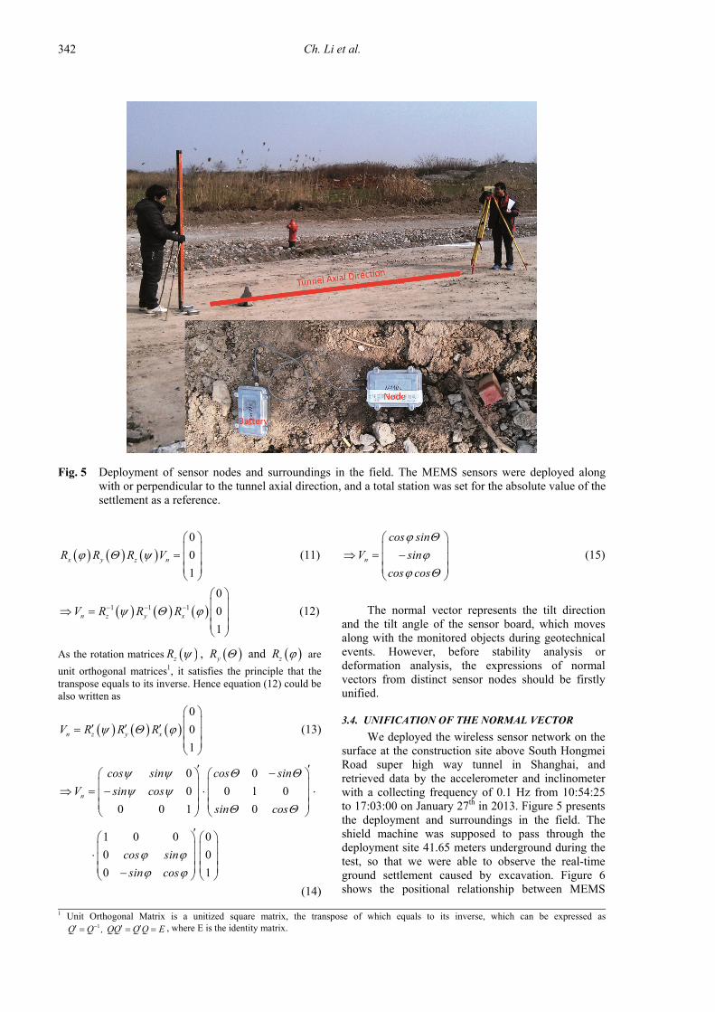
Fig. 5 Deployment of sensor nodes and surroundings in the field. The MEMS sensors were deployed along with or perpendicular to the tunnel axial direction, and a total station was set for the absolute value of the settlement as a reference.
n
cos sin
V sin
cos cos
(15)
The normal vector represents the tilt direction and the tilt angle of the sensor board, which moves along with the monitored objects during geotechnical events. However, before stability analysis or deformation analysis, the expressions of normal vectors from distinct sensor nodes should be firstly unified.
3.4. UNIFICATION OF THE NORMAL VECTOR
We deployed the wireless sensor network on the surface at the construction site above South Hongmei Road super high way tunnel in Shanghai, and retrieved data by the accelerometer and inclinometer with a collecting frequency of 0.1 Hz from 10:54:25 to 17:03:00 on January 27th in 2013. Figure 5 presents the deployment and surroundings in the field. The shield machine was supposed to pass through the deployment site 41.65 meters underground during the test, so that we were able to observe the real-time ground settlement caused by excavation. Figure 6 shows the positional relationship between MEMS
0
0
1x y z nR R R V
(11)
1 1 1
0
0
1n z y xV R R R
(12)
As the rotation matrices zR , yR and zR are
unit orthogonal matrices1, it satisfies the principle that thetranspose equals to its inverse. Hence equation (12) could be also written as
0
0
1n z y xV R R R
(13)
0 0
0 0 1 0
0 0 1 0
1 0 0 0
0 0
0 1
n
cos sin cos sin
V sin cos
sin cos
cos sin
sin cos
(14)
1 Unit Orthogonal Matrix is a unitized square matrix, the transpose of which equals to its inverse, which can be expressed as 1Q Q , QQ Q Q E , where E is the identity matrix.
USE OF MEMS ACCELEROMETERS/INCLINOMETERS AS A GEOTECHNICAL MONITORING … .
343
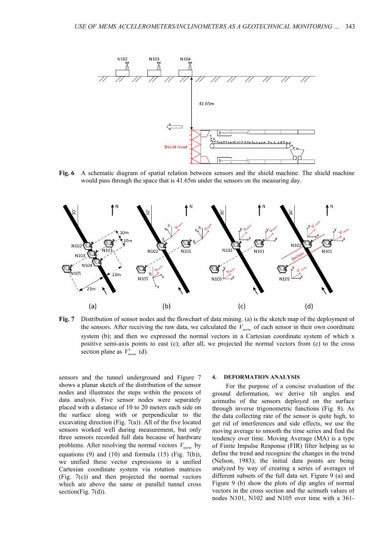
Fig. 6 A schematic diagram of spatial relation between sensors and the shield machine. The shield machinewould pass through the space that is 41.65m under the sensors on the measuring day.
Fig. 7 Distribution of sensor nodes and the flowchart of data mining. (a) is the sketch map of the deployment of the sensors. After receiving the raw data, we calculated the normV of each sensor in their own coordinate
system (b); and then we expressed the normal vectors in a Cartesian coordinate system of which x positive semi-axis points to east (c); after all, we projected the normal vectors from (c) to the cross section plane as normV (d).
4. DEFORMATION ANALYSIS
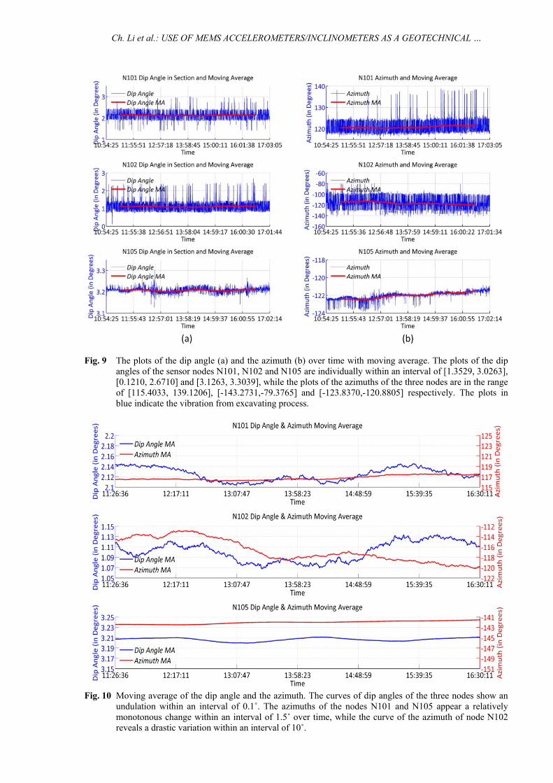
For the purpose of a concise evaluation of the ground deformation, we derive tilt angles and azimuths of the sensors deployed on the surface through inverse trigonometric functions (Fig. 8). As the data collecting rate of the sensor is quite high, to get rid of interferences and side effects, we use the moving average to smooth the time series and find the tendency over time. Moving Average (MA) is a type of Finite Impulse Response (FIR) filter helping us to define the trend and recognize the changes in the trend(Nelson, 1983); the initial data points are being analyzed by way of creating a series of averages of different subsets of the full data set. Figure 9 (a) and Figure 9 (b) show the plots of dip angles of normal vectors in the cross section and the azimuth values of nodes N101, N102 and N105 over time with a 361-
sensors and the tunnel underground and Figure 7 shows a planar sketch of the distribution of the sensor nodes and illustrates the steps within the process of data analysis. Five sensor nodes were separatelyplaced with a distance of 10 to 20 meters each side on the surface along with or perpendicular to the excavating direction (Fig. 7(a)). All of the five located sensors worked well during measurement, but only three sensors recorded full data because of hardwareproblems. After resolving the normal vectors normV by
equations (9) and (10) and formula (15) (Fig. 7(b)),we unified these vector expressions in a unified Cartesian coordinate system via rotation matrices(Fig. 7(c)) and then projected the normal vectors which are above the same or parallel tunnel cross section(Fig. 7(d)).
Ch. Li et al.
344
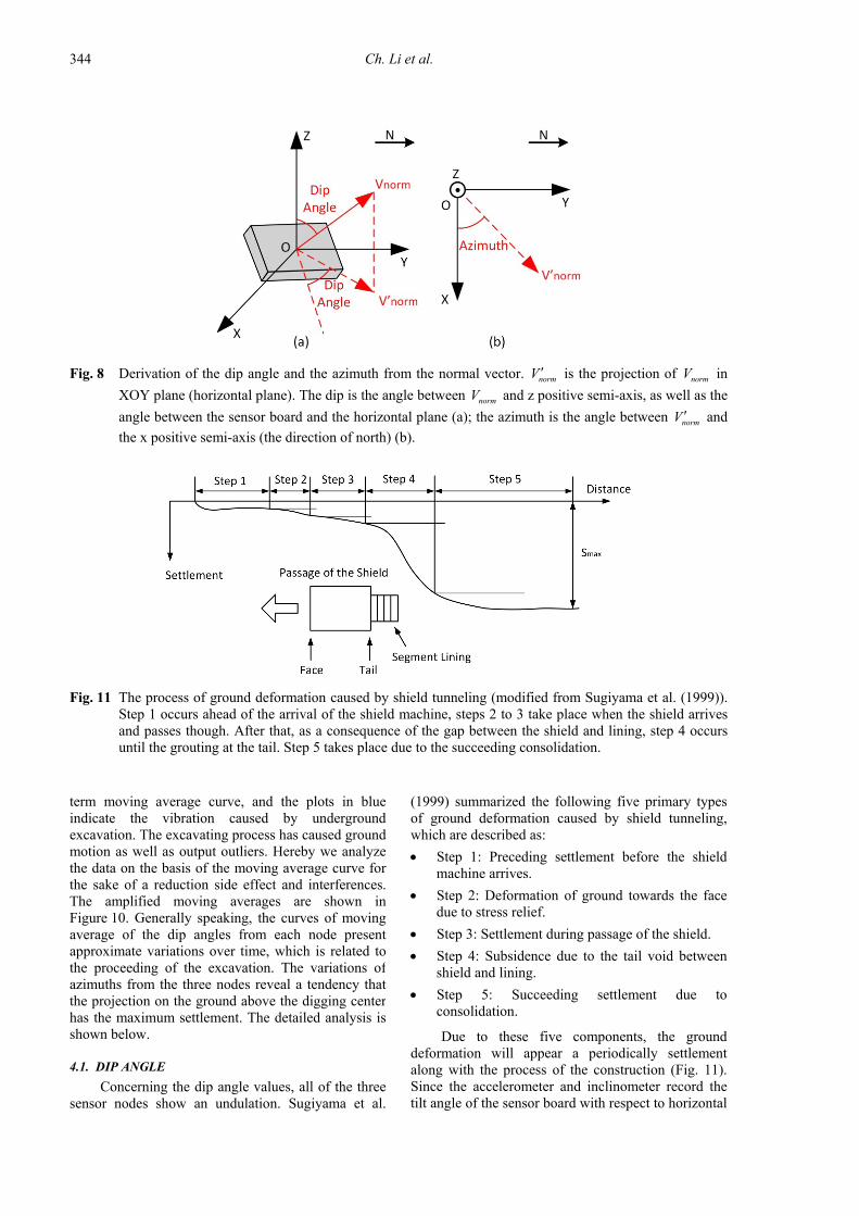
Fig. 8 Derivation of the dip angle and the azimuth from the normal vector. normV is the projection of normV in
XOY plane (horizontal plane). The dip is the angle between normV and z positive semi-axis, as well as the
angle between the sensor board and the horizontal plane (a); the azimuth is the angle between normV and
the x positive semi-axis (the direction of north) (b).
Fig. 11 The process of ground deformation caused by shield tunneling (modified from Sugiyama et al. (1999)).
Step 1 occurs ahead of the arrival of the shield machine, steps 2 to 3 take place when the shield arrives and passes though. After that, as a consequence of the gap between the shield and lining, step 4 occurs until the grouting at the tail. Step 5 takes place due to the succeeding consolidation.
(1999) summarized the following five primary types of ground deformation caused by shield tunneling, which are described as:
Step 1: Preceding settlement before the shield machine arrives.
Step 2: Deformation of ground towards the face due to stress relief.
Step 3: Settlement during passage of the shield.
Step 4: Subsidence due to the tail void between shield and lining.
Step 5: Succeeding settlement due to consolidation.
Due to these five components, the ground deformation will appear a periodically settlement along with the process of the construction (Fig. 11). Since the accelerometer and inclinometer record thetilt angle of the sensor board with respect to horizontal
term moving average curve, and the plots in blue indicate the vibration caused by underground excavation. The excavating process has caused ground motion as well as output outliers. Hereby we analyze the data on the basis of the moving average curve for the sake of a reduction side effect and interferences. The amplified moving averages are shown in Figure 10. Generally speaking, the curves of moving average of the dip angles from each node present approximate variations over time, which is related to the proceeding of the excavation. The variations of azimuths from the three nodes reveal a tendency that the projection on the ground above the digging center has the maximum settlement. The detailed analysis is shown below.
4.1. DIP ANGLE
Concerning the dip angle values, all of the three sensor nodes show an undulation. Sugiyama et al.
USE OF MEMS ACCELEROMETERS/INCLINOMETERS AS A GEOTECHNICAL MONITORING … .
345
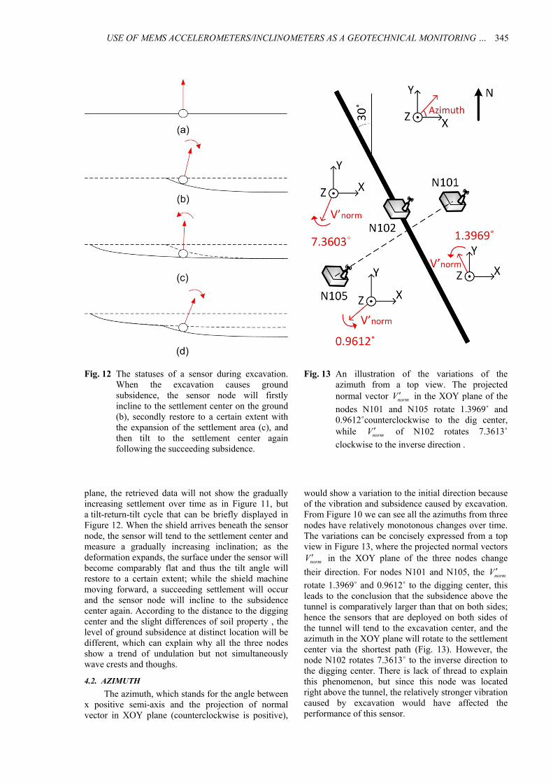
Fig. 12 The statuses of a sensor during excavation. When the excavation causes ground subsidence, the sensor node will firstly incline to the settlement center on the ground (b), secondly restore to a certain extent with the expansion of the settlement area (c), and then tilt to the settlement center again following the succeeding subsidence.
Fig. 13 An illustration of the variations of the azimuth from a top view. The projected normal vector normV in the XOY plane of the
nodes N101 and N105 rotate 1.3969˚ and 0.9612˚counterclockwise to the dig center, while normV of N102 rotates 7.3613˚
clockwise to the inverse direction .
would show a variation to the initial direction because of the vibration and subsidence caused by excavation. From Figure 10 we can see all the azimuths from three nodes have relatively monotonous changes over time. The variations can be concisely expressed from a top view in Figure 13, where the projected normal vectors
normV in the XOY plane of the three nodes change
their direction. For nodes N101 and N105, the normV rotate 1.3969˚ and 0.9612˚ to the digging center, this leads to the conclusion that the subsidence above the tunnel is comparatively larger than that on both sides;hence the sensors that are deployed on both sides of the tunnel will tend to the excavation center, and the azimuth in the XOY plane will rotate to the settlement center via the shortest path (Fig. 13). However, the node N102 rotates 7.3613˚ to the inverse direction to the digging center. There is lack of thread to explain this phenomenon, but since this node was located right above the tunnel, the relatively stronger vibration caused by excavation would have affected the performance of this sensor.
plane, the retrieved data will not show the gradually increasing settlement over time as in Figure 11, but a tilt-return-tilt cycle that can be briefly displayed in Figure 12. When the shield arrives beneath the sensor node, the sensor will tend to the settlement center and measure a gradually increasing inclination; as the deformation expands, the surface under the sensor will become comparably flat and thus the tilt angle will restore to a certain extent; while the shield machine moving forward, a succeeding settlement will occur and the sensor node will incline to the subsidence center again. According to the distance to the diggingcenter and the slight differences of soil property , the level of ground subsidence at distinct location will be different, which can explain why all the three nodes show a trend of undulation but not simultaneously wave crests and thoughs.
4.2. AZIMUTH
The azimuth, which stands for the angle between x positive semi-axis and the projection of normal vector in XOY plane (counterclockwise is positive),
Ch. Li et al.
346
N101, N102 and N105 in the cross section as well as the azimuth value over time. The undulation of the plots of the dip angle is caused by the periodically subsidence during the process of shield tunneling, and their diverse crests and thoughs refer to the different soil properties and the slight distinct distances to the center. The curves of the azimuth from nodes N101 and N105 reveal that both of the sensors tend to incline to the excavating center, which is in accordance with the settlement mechanism caused by underground digging. These results enhance the idea that ground settlement can be monitored with the help of inclinometers or accelerometers by properdeployment. In the follow-up study, the deformedpattern of a surface settlement could be optimized by the fusion of an amount of distinctive types of sensors and the integration of numerical simulation methods, and a well-planned surveillance is strongly expected.
ACKNOWLEDGEMENTS
The field test in Shanghai was supported by Shanghai Tunnel Engineering CO., LTD. Thanks to the staff and the management, for their great arrangement and their kind suggestions before the deployment. Many thanks to Professor Youliang Chen and Xi Du from University of Shanghai for Science and Technology (USST), without their support this deployment test would have been not possible. Thanks to Xuelian Zhou and Qiuyu Song from USST for their kind help concerning the overview of construction site. Special thanks to Laiye Bi from RWTH Aachen University, for his very valuable comments and discussion while developing and deducing the described method.
REFERENCES:
Bitsch Link, J.A., Fabritius, G., Alizai, M.H. and Wehrle,K.: 2010a, BurrowView - Seeing the world through the eyes of rats. 8th IEEE International Conference on Pervasive Computing and Communications Workshops (PERCOM Workshops), March to April 2010, Mannheim, Germany, 56–61. DOI: 10.1109/PERCOMW.2010.5470603
Bitsch Link, J.A., Bretgeld, T., Goliath, A. and Wehrle, K.: 2010b, RatMote: A sensor platform for animal habitat monitoring. Proceedings of the 9th ACM/IEEE international Conference on Information Processing in Sensor Networks, April 2010, Stockholm, Sweden, 432–433. DOI: 10.1145/1791212.1791291
Bitelli, G., Bonsignore, F. and Unguendoli, M.: 2000, Levelling and GPS networks to monitor ground subsidence in the Southern Po Valley. Journal of Geodynamics, 30, No. 3, 355–369. DOI: 10.1016/S0264-3707(99)00071-X
Buckley, S.M., Rosen, P.A., Hensley, S. and Tapley, B.D.: 2003, Land subsidence in Houston, Texas, measured by radar interferometry and constrained by extensometers. Journal of Geophysical Research: Solid Earth, 108, No. B11. DOI: 10.1029/2002JB001848
Cho, C.Y., Chou, P.H., Chung, Y.C., King, C.T., Tsai, M.J.,Lee, B.J. and Chou, T.Y.: 2008, Wireless sensor
4.3. DEFICIENCY AND IMPROVEMENT
For the tunnel case in Shanghai, the inclinations are very low that hardly relevant to the constructions and will not affect the usage. Besides, concerning the quantity of the retrieving data, they are not suitable tobe used in proceeding analysis. First of all, the amount of sensors was quite limited and irregular. Therefore, the data provide only a limited view at one crosssection and do not allow validating the observations within the progress of the construction spatially. Secondly, the measuring was only taken for one day, which is too short to monitor the whole process of ground settlement. Furthermore, as the dip angle only differed with a maximum variation of 0.04˚, it was indeed a test to the performance of the sensor. Even the sensitivity of the inclinometer is 0.00179˚/count in small scope of variation, we must admit that errors and drifts exist and will permanently affect the accuracy of data. Lastly, according to the record from Shanghai Meteorological Bureau, the temperature during the measuring day varied from 4 °C to 10 °C. An offset caused by temperature was existed and would affect the accuracy of the measurement. In other words, we may verify the trend of the inclination of sensors by a tendency analysis, but we should not take every single value as a precise reflection of the tilt angle in this case. To refine the measuring method, we should increase the amount of sensors and prolong the measuring period, uniformly distribute the sensors parallel with and perpendicular to the longitudinal direction of the excavation, and apply numerical simulation methods for settlement predictions and back analysis.
5. CONCLUSIONS
We deployed the ad-hoc X-SLEWS wireless monitoring system at the construction site of South Hongmei Road super high way tunnel in Shanghai and conducted a one-day ground tilting measurement. The main effort of this paper is the coordinate system converting method that we used to transform the output into the normal vector of the sensor board. First of all, we made use of the rotation matrices to deduce an expression of the three weights of the Earth’sgravitational field in the rotated coordinate system. Secondly, we calculated the rotating angle of and
on the basis of the equivalent relations between the output of the sensor and the expressions of the Earth’sgravitational field from the first step. Besides, we took the third rotating value as zero concerning the
relatively simple deformation mode and its slightrelevance to construction safety. Thereby the rotation matrices were solved. After that, we applied theserotation matrices to deduce the normal vector. Furthermore, we unified the normal vector from each sensor in a uniform coordinate system to realize a concise comparison.
In the following deformation analysis, we studied the dip angle of the normal vector of nodes

USE OF MEMS ACCELEROMETERS/INCLINOMETERS AS A GEOTECHNICAL MONITORING … .
347
Nejikovsky, B. and Keller, E.: 2000, Wireless com-munications based system to monitor performance of rail vehicles. Proceedings of the 2000 ASME/IEEE Joint Railroad Conference, April 2000, Newark, U.S.A., 111–124. DOI: 10.1109/RRCON.2000.869993
Nelson, L.: 1983, The deceptiveness of moving averages. Journal of Quality Technology, 15, No. 2, 99–100.
Pedley, M.: 2013, Tilt sensing using a three-axis accelerometer. Free Scale Semiconductor Application Note, Document Number: AN3461, Rev. 6, March 2013.
Shafiullah, G., Gyasi-Agyei, A. and Wolfs, P.: 2007, Survey of wireless communications applications in the railway industry. Proceedings of the 2nd AustralianConference on Wireless Broadband and Ultra Wideband Communications, August 2007, Sydney, Australia, 65. DOI: 10.1109/AUSWIRELESS.2007.74
Stoianov, I., Nachman, L., Madden, S. and Tokmouline, T.: 2007, PIPENET: A wireless sensor network for pipeline monitoring. Proceedings of the 6th
International Symposium on Information Processing in Sensor Networks, April 2007, Cambridge, Massachusetts, USA, 264–273. DOI: 10.1109/IPSN.2007.4379686
Sugiyama, T., Hagiwara, T., Nomoto, T., Nomoto, M., Ano,Y., Mair, R.J., Bolton, M.D. and Soga, K.: 1999, Observations of ground movements during tunnel construction by slurry shield method at the docklands light railway Lewisham extension - East London. Soils and Foundations, 39, No. 3, 99–112.
Tomás, R., Herrera, G., Delgado, J., Lopez-Sanchez, J.M.,Mallorquí, J.J. and Mulas, J.: 2010, A ground subsidence study based on DInSAR data: Calibration of soil parameters and subsidence prediction in Murcia City (Spain). Engineering Geology, 111, No. 1-4, 19–30. DOI: 10.1016/j.enggeo.2009.11.004
Wang, Q.H. and Balasingham, I.: 2010, Wireless sensor networks - An introduction. In: Geoff V Merrett and Yen Kheng Tan (Eds.): Wireless Sensor Networks: Application - Centric Design. InTech, Rijeka, 1–13.DOI: 10.5772/13225
networks for debris flow observation. Proceedings of the 5th Annual IEEE Communications Society Conference on Sensor, Mesh and Ad Hoc Communications and Networks, June 2008, San Francisco, U.S.A., 615–617. DOI: 10.1109/SAHCN.2008.88
Fernandez-Steeger, T., Ceriotti, M., Bitsch Link, J.A., May, M., Hentschel, K. and Wehrle, K.: 2013, “And then, the weekend started": Story of a WSN deployment on a construction site. Journal of Sensor and Actuator Networks, 2, No. 1, 156–171. DOI: 10.3390/jsan2010156
Fernandez-Steeger, T., Arnhardt, C., Walter, K., Hass, S.,Niemeyer, F., Nakaten, B., Homfeld, S., Asch, K.,Azzam, R., Bill, R. and Ritter, H.: 2009, SLEWS - A prototype system for flexible real time monitoring of landslides using an open spatial data infrastructure and wireless sensor networks. GEOTECHNOLOGIEN Science Report 13. Early Warning Systems in Earth Management, 3–15.
Jekeli, C.: 2001, Inertial navigation systems with geodetic applications. Walter de Gruyter, Berlin, New York.
Kim, S., Pakzad, S., Culler, D., Demmel, J., Fenves, G., Glaser, S. and Turon, M.: 2007, Health monitoring of civil infrastructures using wireless sensor networks. Proceedings of the 6th International Symposium onInformation Processing in Sensor Networks (IPSN), April 2007, Cambridge, Massachusetts, U.S.A., 254–263. DOI: 10.1109/IPSN.2007.4379685
Lane, N.D., Miluzzo, E., Lu, H., Peebles, D., Choudhury, T. and Campbell, A.T.: 2010, A survey of mobile phone sensing. Communications Magazine, IEEE, 48, No. 9, 140–150. DOI: 10.1109/MCOM.2010.5560598
Li, M. and Liu, Y.H.: 2009, Underground coal mine monitoring with wireless sensor networks. ACM Transactions on Sensor Networks (TOSN), 5, No. 2. DOI: 10.1145/1498915.1498916
Lynch, J. and Loh, K.: 2006, A summary review of wireless sensors and sensor networks for structural health monitoring. The Shock and Vibration Digest, 38, No. 2, 91–128. DOI: 10.1177/0583102406061499
Maenaka, K.: 2008, MEMS inertial sensors and their applications. Proceedings of the 5th International Conference on Networked Sensing Systems, June 2008, Kanazawa, Japan, 71–73. DOI: 10.1109/INSS.2008.4610869
Martinez, K., Padhy, P., Riddoch, A., Ong, H.L.R. and Hart,J.K.: 2005, Glacial environment monitoring using sensor networks. Proceedings of Workshop on Real-World Wireless Sensor Networks (REALWSN’05), June 2005, Stockholm, Sweden.
May, M., Fernandez-Steeger, T.M. and Bitsch Link, J.A.: 2013, X-SLEWS: Ein neuer flexibler Träger für Sensoren für das Geomonitoring, 19. Tagung für Ingenieurgeologiemit Forum für junge Ingenieurgeologen, March 2013, Munich, Germany, (in German).
Ch. Li et al.: USE OF MEMS ACCELEROMETERS/INCLINOMETERS AS A GEOTECHNICAL …
Fig. 9 The plots of the dip angle (a) and the azimuth (b) over time with moving average. The plots of the dip angles of the sensor nodes N101, N102 and N105 are individually within an interval of [1.3529, 3.0263],[0.1210, 2.6710] and [3.1263, 3.3039], while the plots of the azimuths of the three nodes are in the rangeof [115.4033, 139.1206], [-143.2731,-79.3765] and [-123.8370,-120.8805] respectively. The plots in blue indicate the vibration from excavating process.
Fig. 10 Moving average of the dip angle and the azimuth. The curves of dip angles of the three nodes show anundulation within an interval of 0.1˚. The azimuths of the nodes N101 and N105 appear a relatively monotonous change within an interval of 1.5˚ over time, while the curve of the azimuth of node N102 reveals a drastic variation within an interval of 10˚.
![A 4 mm2 Double Differential Torsional MEMS Accelerometer ...€¦ · MEMS accelerometers based on single-beam structures [22,23]. To further improve the performance and promote the](https://static.fdocuments.in/doc/165x107/5e98a7daca73fa1e6532d761/a-4-mm2-double-differential-torsional-mems-accelerometer-mems-accelerometers.jpg)