“USE OF CFD TOOL FOR IMPROVING DESIGN OF ...€œUse Of Cfd Tool For Improving Design Of...
15
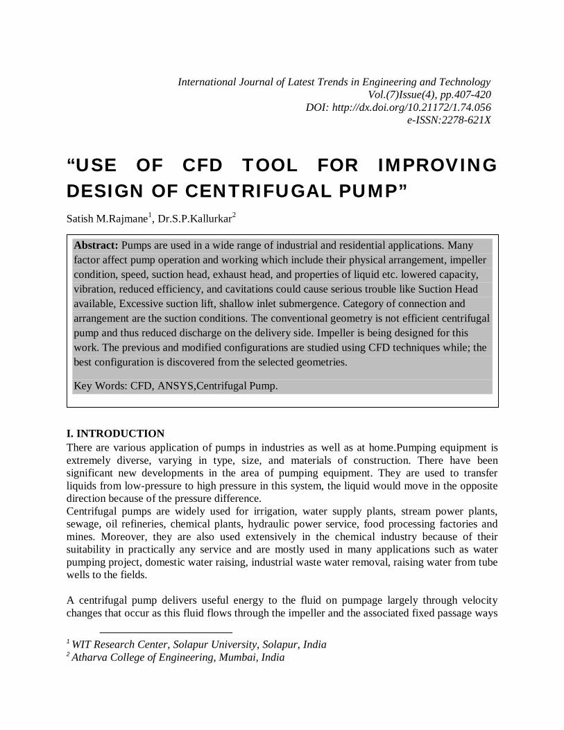
“USE OF CFD TOOL FOR IMPROVING DESIGN OF CENTRIFUGAL PUMP” Satish M.Rajmane 1 , Dr.S.P.Kallurkar 2 I. INTRODUCTION There are various application of pumps in industries as well as at home.Pumping equipment is extremely diverse, varying in type, size, and materials of construction. There have been significant new developments in the area of pumping equipment. They are used to transfer liquids from low-pressure to high pressure in this system, the liquid would move in the opposite direction because of the pressure difference. Centrifugal pumps are widely used for irrigation, water supply plants, stream power plants, sewage, oil refineries, chemical plants, hydraulic power service, food processing factories and mines. Moreover, they are also used extensively in the chemical industry because of their suitability in practically any service and are mostly used in many applications such as water pumping project, domestic water raising, industrial waste water removal, raising water from tube wells to the fields. A centrifugal pump delivers useful energy to the fluid on pumpage largely through velocity changes that occur as this fluid flows through the impeller and the associated fixed passage ways 1 WIT Research Center, Solapur University, Solapur, India 2 Atharva College of Engineering, Mumbai, India International Journal of Latest Trends in Engineering and Technology Vol.(7)Issue(4), pp.407-420 DOI: http://dx.doi.org/10.21172/1.74.056 e-ISSN:2278-621X Abstract: Pumps are used in a wide range of industrial and residential applications. Many factor affect pump operation and working which include their physical arrangement, impeller condition, speed, suction head, exhaust head, and properties of liquid etc. lowered capacity, vibration, reduced efficiency, and cavitations could cause serious trouble like Suction Head available, Excessive suction lift, shallow inlet submergence. Category of connection and arrangement are the suction conditions. The conventional geometry is not efficient centrifugal pump and thus reduced discharge on the delivery side. Impeller is being designed for this work. The previous and modified configurations are studied using CFD techniques while; the best configuration is discovered from the selected geometries. Key Words: CFD, ANSYS,Centrifugal Pump.
Transcript of “USE OF CFD TOOL FOR IMPROVING DESIGN OF ...€œUse Of Cfd Tool For Improving Design Of...
“USE OF CFD TOOL FOR IMPROVING DESIGN OF CENTRIFUGAL PUMP” Satish M.Rajmane1, Dr.S.P.Kallurkar2
I. INTRODUCTION There are various application of pumps in industries as well as at home.Pumping equipment is extremely diverse, varying in type, size, and materials of construction. There have been significant new developments in the area of pumping equipment. They are used to transfer liquids from low-pressure to high pressure in this system, the liquid would move in the opposite direction because of the pressure difference. Centrifugal pumps are widely used for irrigation, water supply plants, stream power plants, sewage, oil refineries, chemical plants, hydraulic power service, food processing factories and mines. Moreover, they are also used extensively in the chemical industry because of their suitability in practically any service and are mostly used in many applications such as water pumping project, domestic water raising, industrial waste water removal, raising water from tube wells to the fields. A centrifugal pump delivers useful energy to the fluid on pumpage largely through velocity changes that occur as this fluid flows through the impeller and the associated fixed passage ways
1 WIT Research Center, Solapur University, Solapur, India 2 Atharva College of Engineering, Mumbai, India
International Journal of Latest Trends in Engineering and Technology Vol.(7)Issue(4), pp.407-420
DOI: http://dx.doi.org/10.21172/1.74.056 e-ISSN:2278-621X
Abstract: Pumps are used in a wide range of industrial and residential applications. Many factor affect pump operation and working which include their physical arrangement, impeller condition, speed, suction head, exhaust head, and properties of liquid etc. lowered capacity, vibration, reduced efficiency, and cavitations could cause serious trouble like Suction Head available, Excessive suction lift, shallow inlet submergence. Category of connection and arrangement are the suction conditions. The conventional geometry is not efficient centrifugal pump and thus reduced discharge on the delivery side. Impeller is being designed for this work. The previous and modified configurations are studied using CFD techniques while; the best configuration is discovered from the selected geometries.
Key Words: CFD, ANSYS,Centrifugal Pump.

“Use Of Cfd Tool For Improving Design Of Centrifugal Pump” 407
of the pump. It is converting of mechanical energy to hydraulic energy of the handling fluid to get it to a required place or height by the centrifugal force of the impeller blade. The input power of centrifugal pump is the mechanical energy and such as electrical motor of the drive shaft driven by the prime mover or small engine. The output energy is hydraulic energy of the fluid being raised or carried. In a centrifugal pump, the liquid is forced by atmospheric or other pressure into a set of rotating vanes. A centrifugal pump consists of a set of rotation vanes enclosed within a housing or casing that is used to impart energy to a fluid through centrifugal force. A pump transfer mechanical energy from some external source to the liquid flowing through it and losses occur in any energy conversion process. The energy transferred is predicted by the Euler Equation. The energy transfer quantities are losses between fluid power and mechanical power of the impeller or runner. Thus, centrifugal pump may be taken losses of energy. The kinds of loss of centrifugal pumps can be differentiated in internal losses and external or mechanical losses. The internal loss is hydraulic losses or blade losses by friction, variations of the effective area or changes of direction losses of quantity at the sealing places between the impeller and housing at the rotary shaft seals. The external or mechanical loss is sliding surface losses by bearing friction or seal friction.
II. LITERATURE REVIEW
Manjunatha, Nataraj J R etc al1In this paper, a design of axial pump is carried out and analyzed to get the best performance point. The design and performance analysis of axial pump are chosen because it is the most useful mechanical rotodynamic machine in fluid works which widely used in domestic, irrigation, industry, large plants and river water pumping system .the pump the head and flow rate of this pump are 8 m and 1000 m3/hour and the speed is 1400 rpm. The performance analysis of axial pump is carried out after designing the dimensions of axial pump. So, impeller friction losses, disk friction losses and recirculation losses of centrifugal pump are also considered in performance analysis of axial pump. The Predicted Head and efficiency is compared with analytical results and it shows the good agreement. Haridass Ramasamy, Prabhu Prakash etc al2 This project deals with the application and need of CFD analysis in the pump industries. For this purpose, we have made a design and analysis of impeller used in Domestic Open well Radial flow water pumps. The impeller selected is of enclosed type, which is commonly used in domestic water pumps. In this project we have designed an impeller for a domestic need using formulas formulated by Dr. K.M Srinivasan, in the book Rotodynamic Pumps. The impeller is modelled using CAD software and analyzed using CFD package. The CFD output is cross checked with desired requirements, so as to state the accuracy and need of CFD analysis. Syam Prasad, BVVV Lakshmipathi Rao, A Babji and Dr P Kumar Babu etc al3 have studied the static and dynamic analysis of a centrifugal pump impeller which is made of three different alloy materials (viz., Inconel alloy 740, Incoloy alloy 803, Warpaloy) to estimate its performance. A structural analysis has been carried out to investigate the stresses, strains and displacements of the impeller and modal analysis has been carried out to investigate the frequency and deflection of the impeller. An attempt is also made to suggest the best alloy for an impeller of a centrifugal pump by comparing the results obtained for three different alloys.
Satish M.Rajmane, Dr.S.P.Kallurkar 408
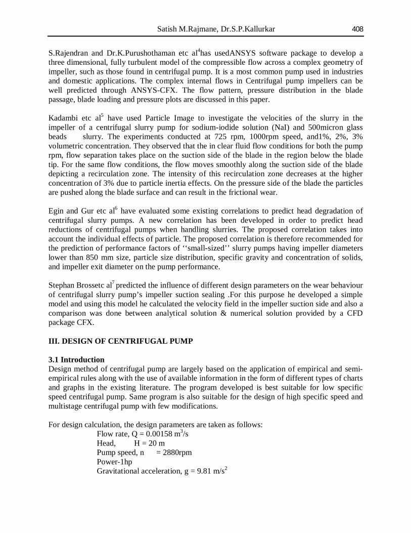
S.Rajendran and Dr.K.Purushothaman etc al4has usedANSYS software package to develop a three dimensional, fully turbulent model of the compressible flow across a complex geometry of impeller, such as those found in centrifugal pump. It is a most common pump used in industries and domestic applications. The complex internal flows in Centrifugal pump impellers can be well predicted through ANSYS-CFX. The flow pattern, pressure distribution in the blade passage, blade loading and pressure plots are discussed in this paper. Kadambi etc al5 have used Particle Image to investigate the velocities of the slurry in the impeller of a centrifugal slurry pump for sodium-iodide solution (NaI) and 500micron glass beads slurry. The experiments conducted at 725 rpm, 1000rpm speed, and1%, 2%, 3% volumetric concentration. They observed that the in clear fluid flow conditions for both the pump rpm, flow separation takes place on the suction side of the blade in the region below the blade tip. For the same flow conditions, the flow moves smoothly along the suction side of the blade depicting a recirculation zone. The intensity of this recirculation zone decreases at the higher concentration of 3% due to particle inertia effects. On the pressure side of the blade the particles are pushed along the blade surface and can result in the frictional wear. Egin and Gur etc al6 have evaluated some existing correlations to predict head degradation of centrifugal slurry pumps. A new correlation has been developed in order to predict head reductions of centrifugal pumps when handling slurries. The proposed correlation takes into account the individual effects of particle. The proposed correlation is therefore recommended for the prediction of performance factors of ‘‘small-sized’’ slurry pumps having impeller diameters lower than 850 mm size, particle size distribution, specific gravity and concentration of solids, and impeller exit diameter on the pump performance. Stephan Brossetc al7 predicted the influence of different design parameters on the wear behaviour of centrifugal slurry pump’s impeller suction sealing .For this purpose he developed a simple model and using this model he calculated the velocity field in the impeller suction side and also a comparison was done between analytical solution & numerical solution provided by a CFD package CFX. III. DESIGN OF CENTRIFUGAL PUMP 3.1 Introduction Design method of centrifugal pump are largely based on the application of empirical and semi-empirical rules along with the use of available information in the form of different types of charts and graphs in the existing literature. The program developed is best suitable for low specific speed centrifugal pump. Same program is also suitable for the design of high specific speed and multistage centrifugal pump with few modifications. For design calculation, the design parameters are taken as follows:
Flow rate, Q = 0.00158 m3/s Head, H = 20 m Pump speed, n = 2880rpm Power-1hp Gravitational acceleration, g = 9.81 m/s2

“Use Of Cfd Tool For Improving Design Of Centrifugal Pump” 409
Density of water, ρ= 1000 kg/m3
3.2 Design Of Impeller 3.2.1 Specific Speed Specific speed of the pump is computed based on the power as well as discharge; different authors expressed the design parameter as function of specific speed
- (3.1) Where, N = speed at pump shaft rotated. Q = discharge in m3 / sec H = net head in m. For given data N= 12.11 RPM The specific speed determines the general shape or class of the impeller as depicted in Fig.3.1. As the specific speed increases, the ratio of the impeller outlet diameter, D2, to the inlet or eye diameter, Di, decreases. This ratio becomes 1.0 for a true axial flow impeller.
Fig 3.1 Values of Specific Speed
Radial flow impellers develop head principally through centrifugal force. Pumps of higher specific speeds develop head partly by centrifugal force and partly by axial force. A higher specific speed indicates a pump design with head generation more by axial forces and less by centrifugal forces. An axial flow or propeller pump with a specific speed of 10,000 or greater generates it's head exclusively through axial forces. Radial impellers are generally low flow high head designs whereas axial flow impellers are high flow low head designs.

Satish M.Rajmane, Dr.S.P.Kallurkar 410
Fig 3.2 Values Of Efficiency At Specific Speed
3.2.2Power Input And Shaft Input Power Overall efficiency taking by the graph, input power required 15% more because of bearing and transmission loss consider
- (3.2) Where, g= Acceleration due to gravity ρ=Density of the fluid Pin=Power Input H =Head of the Pump Q= Pump Discharge
Pin= 118.5 HP = 388 W
WHP = 1.15*Pin= 0.6 HP
= 446 W
3.2.3 Shaft Diameter Torque,
Assuming a shear stress of 4000 psi
Dsh= 6.5 mm 3.2.4 Hub Diameter The diameter of the hub is given as:

“Use Of Cfd Tool For Improving Design Of Centrifugal Pump” 411
Dh = 1.2 x Dsh Dh= 7.8 mm
3.2.5 Outlet Blade Velocity (U2) Head Coefficient φ = pressure head generated / maximum Euler head Generally, φ = 0.5 to 0.6 So, φ has been taken as 0.58 for design calculation
U2= 20.5 m/s
3.2.6 Outlet Diameter (D2)
D2 = 136 mm
Fig3.3 Slip Vs Flow Coefficient
3.2.7 Flow Coefficient Ф = Vm2 / U2 = Flow velocity / Blade velocity Ф taken 0.1 to 0.2 As, Vm2 = Ф U2 Mean meridional velocity of the steam just after entering the blade passage is denoted by Vm1 is the mean meridional velocity of steam just prior to blade inlet. Vm2 denotes the meridional velocity at the exit of the impeller. Ratio of√2gh is known as capacity constant. For given data Vm1 = .175 x 20.5 = 3.6 m/sec
Vm2 = 1.15 x 3.6 = 4.1 m/sec
3.2.8 Impeller Eye Diameter (DE)

Satish M.Rajmane, Dr.S.P.Kallurkar 412
De = 25 mm
3.2.9 Inlet Diameter (D1)
D1 = (De + 0.020) m = 45mm 3.2.10 Inlet Blade Velocity (U1)
= 6.7 m/s 3.2.11 Inlet Blade Angle (Β1) Fluid at inlet assumed no pressure whirl
Thickness of the blade is mostly taken leading and trailing tips are 4 mm and 5 mm, respectively
β1= 28 0
3.2.12 Width Of Impeller (B)
3.2.13 Blade Angle At Outlet (Β2) Kovats recommends the equation
β2= 24.7
Assuming the fluid stream is entering the impeller without pre rotation and circulation is zero

“Use Of Cfd Tool For Improving Design Of Centrifugal Pump” 413
Fig 3.4 Outlet Velocity Triangle
3.2.14 Number Of Blades (Z) Number of blades generally taken between 4 to 12.
Z ≈ 8 IV. MODELLING OF CENTRIFUGAL PUMP
4.1 Geometric Modeling of Pump
In order to obtain better design in CFD, following procedure is applied so that fluid flow can easily be modelled. Initial design of the model is a planning decision and the geometry is generated depending on these initial design considerations, using either CFD modelling tools or other Design tools. The first task to accomplish in a numerical flow simulation is the definition of the geometry, followed by the grid generation. This step is the most important step for the study of an isolated impeller assuming an axis symmetric flow simplifies the domain to a single blade passage.
Fig4.1 Flow Chart Showing CFD Solving Methodology

Satish M.Rajmane, Dr.S.P.Kallurkar 414
Before the modelling of blade, a generalized program is written for the design of the blade. The program is based on the design methodology discussed in the previous chapter. The parameters which were considered initially are Head, Flow Rate, Pump Speed, Volumetric efficiency and Overall Efficiency. The output of the program is given in the table. Some of the output parameters of this design were used as input of the Blade Modeller.
Fig. 4.2 Blade Model & Pump Model
4.2Convergence Criteria The iterative process is repeated until the change in the variable from one iteration to the next becomes so small that the solution can be considered converged. At convergence: All discrete conservation equations (momentum, energy, etc.) are obeyed in all cells to a specified tolerance. The solution no longer changes with additional iterations. Mass, momentum, energy and scalar balances are obtained. Residuals measure imbalance (or error) in conservation equations. The convergence of the simulations is said to be achieved when all the residuals reach the required convergence criteria. These convergence criteria are found by monitoring the in the drag. The convergence criterion for the continuity equation is 1E-4 and it is set to 1E-3 for the momentum, k and ω equations. The convergence of the residuals is shown in Fig.4.3
Fig.4.3 Convergence Criteria

“Use Of Cfd Tool For Improving Design Of Centrifugal Pump” 415
V. CFD ANALYSIS
5.1 Flow Distribution In Impeller At Different Span The pressure increases gradually along stream wise direction within impeller passage and has higher pressure in pressure side than suction side of the impeller blade. However, the pressure developed inside the impeller is not so uniform. The isobar lines are not all perpendicular to the pressure side of the blade inside the impeller passage; this indicated that there could be a flow separation because of the pressure gradient effect. The fig [5.1 and5.2] shows the pressure distribution within the impeller at two different spans i.e. 50 and 80.
Fig.5. 1 Pressure Distribution At 50 Span
Fig.5. 2 Pressure Distribution At 80 Span

Satish M.Rajmane, Dr.S.P.Kallurkar 416
Velocity also increases gradually along stream wise direction within the impeller passage. As the flow enters the impeller eye, it is diverted to the blade-to-blade passage. The flow at the entrance is not shock less because of the unsteady flow entering the impeller passage. The separation of flow can be seen at the blade leading edge. Since, the flow at the inlet of impeller is not tangential to the blade, the flow along the blade is not uniform and hence the separation of flow takes place along the surface of blade. Here it can be seen that flow separation is taking place on both side of the blade, i.e., pressure and suctionside.
Fig.5. 3 Velocity Distribution At 50 Span
Fig.5.4 Velocity Distribution At 80 Span

“Use Of Cfd Tool For Improving Design Of Centrifugal Pump” 417
5.2 Pressure And Velocity Between Impeller Blades There is distribution of total pressure between the blades of theimpeller. The lowest total pressure appears at the inlet of the impeller suction side. This is the position where cavitation often appears in the centrifugal pump. The highest total pressure occurs at the outlet of impeller, where the kinetic energy of flow reaches maximum. It is observed that the static pressure inside the impeller blades is asymmetry distributed. The minimum static pressure area appears at the back of the impeller blade i.e. suction side, at the inlet. The fig [5.3] shows the relative velocity distribution at 50 span between two blades of the impeller. The rising flow speed of the fluid from inlet to outlet reaches maximum at the impeller blade outlet. From the pressure distribution plot, pressure gradient changes gradually from inlet radius to outlet radius for each impeller. In order to transmit power to the liquid, pressure on the leading or pressure side of the vane should be higher than pressure on the suction side of the vane. Any force exerted by the vane on the liquid has an equal and opposing reaction from the liquid and this can exist only as a pressure difference on two sides of impeller vanes. The immediate effect of such a pressure distribution is that relative velocities near the suction side of the impeller vanes are higher than those near the pressure side of the vane as shown in the fig [5.5 and 5.6].
Fig.5.5 Velocity Vectors At 50% Span

Satish M.Rajmane, Dr.S.P.Kallurkar 418
Fig.5.6 Velocity Vectors At 80% Span
5.4 Blade Loading At Pressure And Suction Side The blade loading of pressure and suction side are drawn at three different locations on the blade at the span of 50 and 80 from hub towards the shroud. The pressure loading on the impeller blade is shown in fig [5.7]. Pressure load on the impeller blade is plot along the stream wise direction. The pressure difference on the pressure and suction sides of the blade suggests that the flow inside the impeller experiences the shearing effects due to the pressure difference on blade-to-blade passage wall.
Fig.5.7 Blade Loading At 50% Span
“Use Of Cfd Tool For Improving Design Of Centrifugal Pump” 419
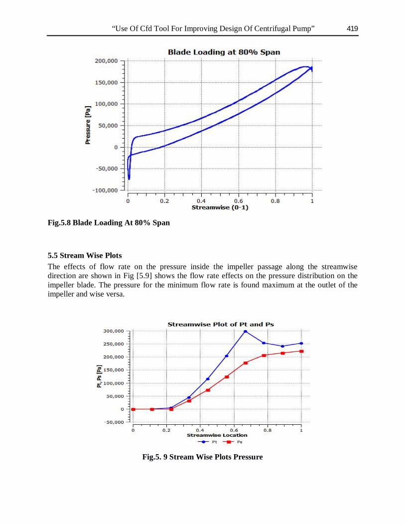
Fig.5.8 Blade Loading At 80% Span
5.5 Stream Wise Plots The effects of flow rate on the pressure inside the impeller passage along the streamwise direction are shown in Fig [5.9] shows the flow rate effects on the pressure distribution on the impeller blade. The pressure for the minimum flow rate is found maximum at the outlet of the impeller and wise versa.
Fig.5. 9 Stream Wise Plots Pressure

Satish M.Rajmane, Dr.S.P.Kallurkar 420
6. CONCLUSIONS
A numerical model of an impeller has been successfully generated and the complex internal flow fields are investigated by using the ANSYS-CFX code. Simulation results are obtained at different flow rates, speeds and concentrations. The internal flow is not quite smooth in the suction and pressure side of the blade due to non tangential inflow conditions which results in the flow separation at the leading edge. The pressure increases gradually along the stream wise direction. The regions in the impeller experiencing the largest pressure were located at the outlet. At low flow rates strong recirculation of flow takes place in suction side of the blade, whereas the flow in pressure side is smooth. But as the flow rate increases the flow separation along the pressure side of the impeller blade takes place, which results in the recirculation of flow in the pressure side. The recirculation in the suction side of the impeller blade decreases as the flow rate increases. Increased flow velocity can be observed at the blade inlet due to the blockage of the flow towards the suction side of the impeller blade. It further increases with increase in the flow rate of the impeller passage in the pump.
The performance results show that total static head is the function of the mass flow rate with constant operating speed. Numerical performance results compared with the experimental results at the same operating conditions.
REFERENCES
1. Manjunatha, Nataraj J R (2015) “Design And Analysis Of Impeller Blade For Axial Flow Pumps” International Journal of Engineering Researches and Management Studies ,May 2015
2. Haridass Ramasamy, Prabhu Prakash (2015) “CFD Approach in the Design of Radial Flow Centrifugal Pump Impeller” International Journal of Scientific Engineering and Applied Science, Volume-1, Issue-5, August 2015, Pg.500-503.
3. A Syam Prasad, BVVV Lakshmipathi Rao, A Babji, Dr P Kumar Babu(2013) “Static and Dynamic Analysis of a Centrifugal Pump Impeller” International Journal of Scientific & Engineering Research, Volume 4, Issue 10, October-2013, Pg.966-971
4. S.Rajendran and Dr.K.Purushothaman,(2012) “Analysis Of Centrifugal Pump Impeller Using ANSYS-CFX” International Journal of Engineering Research & Technology ,Vol. 1 Issue 3, May - 2012 ,Pg.1-6.
5. J.R.Kadambi,Charoenngam P,Subramanian A, Mark P.Wernet,John M.Sankovic, Addie G, Courtwright
R(2004),”Investigation of Particle Velocities in a Slurrypump using PIV:Part 1,The Tongue and Adjacent Channel Flow” Journal Of Energy Resources Technology,ASME. December 2004 Vol-126/271.
6. Tahsin Engin, Mesut Ger., (2003),” Comparative Evaluation of Some ExistingCorrelations to Predict Head
Degradation of Centrifugal Slurry Pumps”, Journal of fluid Engineering, Vol. January 2003.
7. Bross, S., Addie, G.R., (2002), “Prediction of Impeller Nose Wear Behaviour in Centrifugal Slurry Pumps,” 4th International Conference on Mulitphase Flow, New Orleans, LA, USA.