USB Type-CTM Audio Adapter Accessory Mode Reference · PDF fileUSB Type-C Audio Adapter...
32
D+ D- D- D+ SBU2 SBU1 Audio Codec TS5USBA224 Autonomous audio headset Mic/GND detection switch D- D+ D+ D- SBU2 SBU1 Headset/Speaker TS3A227E TUSB32X CC1/CC2 detection device or TPS65982 USB Type-C Connector on audio accessory USB Type-C Connector on notebook or smart phone CC2 CC2 CC1 CC1 Ra D+/- D+/- GPIO Ra Ra L/R L/R Mic/GND Mic/GND USB PHY Ra Audio Accessory Notebook or smart phone 1 TIDUB66 – May 2016 Submit Documentation Feedback Copyright © 2016, Texas Instruments Incorporated USB Type-C Audio Adapter Accessory Mode Reference Design TI Designs USB Type-C Audio Adapter Accessory Mode Reference Design Type-C, Keystone are trademarks of Texas Instruments. WEBENCH is a registered trademark of Texas Instruments. Dell is a trademark of Dell Inc. Foxconn is a trademark of Hon Hai Industry Co. Ltd. Lintes Technology is a trademark of Lintes Technlogy Co. Ltd. Windows is a registered trademark of Microsoft Corportation. ABRACON is a trademark of Mouser Electronics. Vishay-Dale, C&K Components are trademarks of Mouser Electronics Inc. MuRata is a trademark of MuRata Manufacturing Co. Ltd. OSRAM is a trademark of OSRAM Licht AG. Omron Electronic Components is a trademark of Omron Corporation. Samsung is a trademark of Samsung Electronics. Sullins Connector Solutions is a trademark of Sullins Connector Solutions Inc. TDK is a registered trademark of TDK Corporation. Taiyo Yuden is a trademark of Tauyo Yuden Co. Ltd. Aardvark, Total Phase are trademarks of Total Phase Inc. Winbond is a registered trademark of Windbond Electronics Corporation. Yageo America is a trademark of Yageo America. All other trademarks are the property of their respective owners. TI Designs TI Designs provide the foundation that you need including methodology, testing and design files to quickly evaluate and customize the system. TI Designs help you accelerate your time to market. Design Resources TIDA-00565 Tool Folder Containing Design Files TS5USBA224 Product Folder TS3A227E Product Folder TPS65982-EVM Product Folder ASK Our E2E Experts Design Features • Replaces Large 3.5 mm Audio Jack With Smaller Type-C Connector • Supports Analog Audio Through USB Type-C Connector • Supports USB Power Delivery Featured Applications • USB-Type C TM • Portable Electronics • PC Docking Station • Smart Phone
Transcript of USB Type-CTM Audio Adapter Accessory Mode Reference · PDF fileUSB Type-C Audio Adapter...

D+
D-
D-
D+
SBU2
SBU1
Audio Codec
TS5USBA224
Autonomous audio headset Mic/GND detection switch
D-
D+
D+
D-
SBU2
SBU1
Headset/Speaker
TS3A227E
TUSB32X
CC1/CC2
detection
device
or
TPS65982
USB Type-C Connector on
audio accessory
USB Type-C Connector on notebook or smart phone
CC2CC2
CC1CC1Ra
D+/-
D+/-
GPIO
Ra
Ra
L/R L/R
Mic/GNDMic/GND
USB PHY
Ra
Audio Accessory Notebook or smart phone
1TIDUB66–May 2016Submit Documentation Feedback
Copyright © 2016, Texas Instruments Incorporated
USB Type-C Audio Adapter Accessory Mode Reference Design
TI DesignsUSB Type-C Audio Adapter Accessory Mode ReferenceDesign
Type-C, Keystone are trademarks of Texas Instruments.WEBENCH is a registered trademark of Texas Instruments.Dell is a trademark of Dell Inc.Foxconn is a trademark of Hon Hai Industry Co. Ltd.Lintes Technology is a trademark of Lintes Technlogy Co. Ltd.Windows is a registered trademark of Microsoft Corportation.ABRACON is a trademark of Mouser Electronics.Vishay-Dale, C&K Components are trademarks of Mouser Electronics Inc.MuRata is a trademark of MuRata Manufacturing Co. Ltd.OSRAM is a trademark of OSRAM Licht AG.Omron Electronic Components is a trademark of Omron Corporation.Samsung is a trademark of Samsung Electronics.Sullins Connector Solutions is a trademark of Sullins Connector Solutions Inc.TDK is a registered trademark of TDK Corporation.Taiyo Yuden is a trademark of Tauyo Yuden Co. Ltd.Aardvark, Total Phase are trademarks of Total Phase Inc.Winbond is a registered trademark of Windbond Electronics Corporation.Yageo America is a trademark of Yageo America.All other trademarks are the property of their respective owners.
TI DesignsTI Designs provide the foundation that you needincluding methodology, testing and design files toquickly evaluate and customize the system. TI Designshelp you accelerate your time to market.
Design Resources
TIDA-00565 Tool Folder Containing Design FilesTS5USBA224 Product FolderTS3A227E Product FolderTPS65982-EVM Product Folder
ASK Our E2E Experts
Design Features• Replaces Large 3.5 mm Audio Jack With Smaller
Type-C Connector• Supports Analog Audio Through USB Type-C
Connector• Supports USB Power Delivery
Featured Applications• USB-Type CTM
• Portable Electronics• PC Docking Station• Smart Phone

Quick Start Guide www.ti.com
2 TIDUB66–May 2016Submit Documentation Feedback
Copyright © 2016, Texas Instruments Incorporated
USB Type-C Audio Adapter Accessory Mode Reference Design
An IMPORTANT NOTICE at the end of this TI reference design addresses authorized use, intellectual property matters and otherimportant disclaimers and information.
1 Quick Start Guide
1.1 Getting Started HardwareRequired hardware for a demonstration of the audio adapter accessory mode:• TIDA-00565 demo board.• 19 V barrel jack power supply for the TIDA-00565 board.• An audio source such as a PC or a smart phone.• Cable with a 3.5 mm male jack to a 3.5 mm male jack to interface the audio source to the 3.5mm jack
on the TIDA00565 board• Pair of headphones or speaker• USB Type-C audio adapter with a 3.5 mm female jack to a USB Type-C male connector. (not needed if
an audio headset or speaker with a USB Type-C connector is available)
1.2 Getting Started Procedure1. Plug in a 19 V power supply into the barrel jack of the TIDA-00565 board which provides power.2. Plug in an audio source into the 3.5 mm jack of the TIDA-00565 board.3. Plug in a pair of headphones and a speaker with a USB Type-C connector, or use the audio adapter
board to interface the headphones and speaker with a 3.5 mm jack to USB Type-C Connector.
Figure 1 shows the TIDA-00565 with 19 V barrell jack power supply, 3.5mm male to male cable,headphones, and 3.5 mm jack to the USB Type-C adaptor board.
Figure 1. TIDA-00565 and 3.5 mm Jack to The USB Type-C Adaptor Board

TS5USBA224
Used to switch the
D+/D- trace from USB
Type C connector to
the L/R or D+/D-
traces
3.5mm Jack
Plug in the audio
source into this
connector
TPS65982
Full featured power
delivery IC. Only
leveraging CC1 and
CC2 detection feature
for this design
USB Type-C
Connector
Plug in USB type C
audio accessory
adapter into this
connector
Barrel Jack
Plug in power supply into
this socket
www.ti.com Quick Start Guide
3TIDUB66–May 2016Submit Documentation Feedback
Copyright © 2016, Texas Instruments Incorporated
USB Type-C Audio Adapter Accessory Mode Reference Design
Figure 2 shows the location of the key components on the TIDA-00565 board.
Figure 2. Location of Key Components on the TIDA-00565 Board
1.3 Purpose of TS5USBA224The TS5USBA224 is used to multiplex between the USB 2.0 data and analog audio in order to protect theUSB PHY from the negative voltage swings of the analog audio. The analog audio and USB data travelover the D+ and D- lines in the USB Type-C connector. When an analog audio signal is on the USB D+and D- lines, the signal may swing up to –2 to 2 Vpp. This negative swing in voltage can cause damage tocomponents in the signal chain that may not be able to handle a negative swinging signal.
The TS3A227E is used specifically to automatically detect and orient the MIC and GND signals of the 3.5mm jack to support the function described in the USB Type-C standard above. Refer to the TS3A227EAutonomous Audio Accessory Detection and Configuration Switch datasheet (SCDS358B) for more detailson the automated detection. The USB Type-C to 3.5 mm dongle is on the sink side of the system,therefore, the system user may connect speakers or a headphone set to listen to the audio. Headphonesoften come with a 4-pole jack, which means the MIC and GND of the jack must be routed properly.
1.4 Purpose of the TS3A227EThe USB Type-C standard states, “The system shall connect A6/B6, A7/B7, A8 and B8 to an appropriateaudio codec upon entry into the audio adapter accessory mode. The connections for A8 (SBU1) and B8(SBU2) pins are dependent on the adapter’s orientation. Depending on the orientation, the microphoneand analog ground pins may be swapped. These pins are already reversed between the two majorstandards for headset jacks and support for this is built into the headset connection of many codecs, ormay be implemented using an autonomous audio headset switch. The system works correctly with eitherconfiguration."
1.5 Purpose of the TUSB321X / TPS65982The TUSB32X or TPS65982 device enables USB Type-C ports with the configuration channel (CC) logicneeded for USB Type-C ecosystems. The TUSB32X/TPS65982 device use the CC pins to determine thetype of device inserted into the USB Type-C connector. When the TUSB32X/TPS65982 device sees anaudio accessory (by sensing the Ra 1k pull down resistors on the accessory) it can use one of its GPIOsto toggle the TS5USBA224 logic control pins to select the audio path of the TS5USBA224.

Design Overview www.ti.com
4 TIDUB66–May 2016Submit Documentation Feedback
Copyright © 2016, Texas Instruments Incorporated
USB Type-C Audio Adapter Accessory Mode Reference Design
2 Design OverviewThe USB Type-CTM audio adapter accessory mode reference design provides the solution for interfacinganalog audio through the emerging USB Type-C interface. This reference design demonstrates howanalog audio may be transmitted to system peripherals using the USB Type-C standard’s audio adapteraccessory mode. This allows designs to remove the large 3.5 mm jack, and replace it with an 85% smallerUSB Type-C receptacle.
3 Key System SpecificationsTable 1 shows the USB Type-C Analog Audio Pin Electrical Parameter Ratings.
Table 1. USB Type-C Analog Audio Pin Electrical Parameter Ratings
PLUGPIN USB NAME
ANALOGAUDIO
FUNCTIONMIN. MAX. UNITS NOTES
A6/B6 Dp Right –3.0 3.0 V A6 and B6 must be shorted togetherin the analog audio adapter.
A7/B7 Dn Left –3.0 3.0 V A7 and B7 must be shorted togetherin the analog audio adapter.
A8 SBU1 Mic/AGND –0.4 3.3 VB8 SBU2 AGND/Mic –0.4 3.3 V
4 System DescriptionThe USB Type-C audio adapter accessory mode reference design is composed of two boards; a USBType-C analog audio multiplexer board and a USB Type-C connector to a 3.5 mm jack adapter. The USBType-C analog audio multiplexer board controls the switching between analog audio transferred throughthe USB Type-C connector and data transferred through the USB Type-C connector. The USB Type-C to3.5 mm jack adapter board provides the required pull down resistors for the USB Type-C presence detectlogic on CC1 and CC2 that signifies an audio adapter is being used. The adapter also allows users to testaudio with existing audio devices that use the 3.5 mm jack interface.

D+
D-
D-
D+
SBU2
SBU1
Audio Codec
TS5USBA224
Autonomous audio headset Mic/GND detection switch
D-
D+
D+
D-
SBU2
SBU1
Headset/Speaker
TS3A227E
TUSB32X
CC1/CC2
detection
device
or
TPS65982
USB Type-C Connector on
audio accessory
USB Type-C Connector on notebook or smart phone
CC2CC2
CC1CC1Ra
D+/-
D+/-
GPIO
Ra
Ra
L/R L/R
Mic/GNDMic/GND
USB PHY
Ra
Audio Accessory Notebook or smart phone
www.ti.com Block Diagram
5TIDUB66–May 2016Submit Documentation Feedback
Copyright © 2016, Texas Instruments Incorporated
USB Type-C Audio Adapter Accessory Mode Reference Design
5 Block DiagramThe USB-C Analog Audio TI Design allows for analog audio to be passed over USB Type-C connectionwhile protecting the USB PHY from negative voltages swings from the analog audio. In Figure 3, the audiosource may be produced through a computer, while the audio sink may be a speaker to listen to the audio.Figure 3 shows the TIDA00565 functional block diagram.
Figure 3. TIDA00565 Functional Block Diagram

System Design Theory www.ti.com
6 TIDUB66–May 2016Submit Documentation Feedback
Copyright © 2016, Texas Instruments Incorporated
USB Type-C Audio Adapter Accessory Mode Reference Design
6 System Design TheoryThis TIDA00565 system is designed to prove in a simple demonstration how analog audio may be passedover USB Type-C connector. Left and right analog audio is passed through the USB-C connector throughthe D+ and D- lines of the USB Type-C connector. Simply passing audio through USB-C is possiblewithout the use of ICs, but it is not practical as the negative signal swing of the audio signal can damageother components in the system. The TS5USBA224 provides the ability to pass analog audio withoutallowing the negative signal swing of the audio damage any other parts of the system
6.1 USB Type-C Audio Adapter Accessory ModeAnalog audio headsets are supported by multiplexing four analog audio signals onto pins on the USBType-C ™connector when in the audio adapter accessory mode. The audio adapter accessory mode isdeclared to the host by placing two (Ra) pull down resistors on the CC1 and CC2 pins. These resistors onthe CC lines are dictated by the USB Type-C specification.
The four analog audio signals are the same as those used by a traditional 3.5 mm headset jack. Thisadapter makes it possible to interface existing analog headsets with a 3.5 mm to USB Type-C adapter forthis demonstration. The adapter also provides the two 1k ohm (Ra) pull down resistors.Figure 4 shows theexample schematics of a passive 3.5 mm jack to the Type-C connector adapter.
Figure 4. Example Schematic of a Passive 3.5 mm Jack to the USB Type-C Connector Adapter
www.ti.com System Design Theory
7TIDUB66–May 2016Submit Documentation Feedback
Copyright © 2016, Texas Instruments Incorporated
USB Type-C Audio Adapter Accessory Mode Reference Design
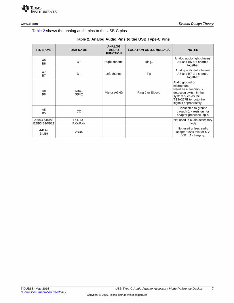
Table 2 shows the analog audio pins to the USB-C pins.
Table 2. Analog Audio Pins to the USB Type-C Pins
PIN NAME USB NAMEANALOG
AUDIOFUNCTION
LOCATION ON 3.5 MM JACK NOTES
A6B6 D+ Right channel Ring1
Analog audio right channelA6 and B6 are shorted
together
A7B7 D– Left channel Tip
Analog audio left channelA7 and B7 are shorted
together
A8B8
SBU1SBU2 Mic or AGND Ring 2 or Sleeve
Audio ground ormicrophone.Need an autonomousdetection switch in thesystem such as theTS3A227E to route thesignals appropriately.
A5B5 CC
Connected to groundthrough 1 k resistors foradapter presence logic.
A2/A3 A10/AllB2/B3 B10/B11
TX+/TX–RX+/RX–
Not used in audio accessorymode.
A4/ A9B4/B9 VBUS
Not used unless audioadapter uses this for 5 V
500 mA charging.
Total Harmonic Distortion Measurement (THD+N) www.ti.com
8 TIDUB66–May 2016Submit Documentation Feedback
Copyright © 2016, Texas Instruments Incorporated
USB Type-C Audio Adapter Accessory Mode Reference Design
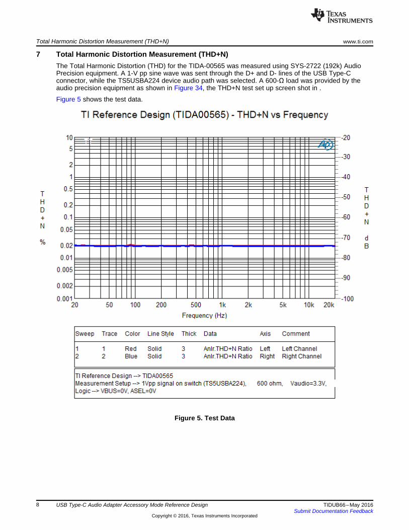
7 Total Harmonic Distortion Measurement (THD+N)The Total Harmonic Distortion (THD) for the TIDA-00565 was measured using SYS-2722 (192k) AudioPrecision equipment. A 1-V pp sine wave was sent through the D+ and D- lines of the USB Type-Cconnector, while the TS5USBA224 device audio path was selected. A 600-Ω load was provided by theaudio precision equipment as shown in Figure 34, the THD+N test set up screen shot in .
Figure 5 shows the test data.
Figure 5. Test Data

Back to Back N FET Configuration
GND GND
GNDGND
GND
D1
21 ohm
L1
DNP R48
0 R60DNP R58
DNP R640 R62
DNP R57
0.01R1
GND
GND
DNP R51
DNP R35
DNP R53
DNP R59DNP R61DNP R63DNP R65
GNDDNP R50DNP R47
0 R46
DNP R68DNP R670 R66
DNP R18DNP R19DNP R23
0 R410 R39
DNP R37
GND
0R3
0R2
0R5
0R6
220pFC19
220pFC15
GND
1µFC6
10µFC1
DNP R54
VBUS
0R10
DNPR22
0R11
DNPR30
GND
0.01µFC7
0.01µFC8
0.01µFC9
0.01µFC10
D1+1
D1-2
NC6
NC7
NC9
NC10
D2+4
D2-5
GND3
GND8
U3
TPD4E05U06DQA
D1+1
D1-2
NC6
NC7
NC9
NC10
D2+4
D2-5
GND3
GND8
U4
TPD4E05U06DQA
7,8 1,2,3
5,6,
Q2
7,81,2,3
5,6,
Q1
GND
63
1 8
2 7
54
S1
1
3
56
4
2
7
910
8
12 11
14 13
16 15
18 17
20 19
J2
1
3
56
4
2
7
910
8
12 11
14 13
16 15
18 17
20 19
J3
0.22µFC3
3.83kR753.83kR76
3.83kR79
TP1
TP2
TP3
J6
TP4
3.83kR20
100k R24
GND
100kR26
0.01µFC53
GND
Tiva_5VTiva_3V3
1.00kR121.00kR131.00kR141.00kR15
External Power
15.0kR28
DNP R31DNP R34
0 R380 R400 R690 R71
DNP R36DNP R32DNP R17DNP R16
3
1
2
Q4
White
12
D3
560R73
3
1
2
Q5
White
12
D4
560R74
3
1
2
Q6
White
12
D5
560R86
3
1
2
Q7
White
12
D6
560R87
3
1
2
Q3
White
12
D2
560R72
3
1
2
Q8
White
12
D7
560R89
3
1
2
Q9
White
12
D8
560R90
GND
White
12
D9
3
1
2
Q10
560R96
100k
R70
GND
SPI_SSZB3
SPI_MOSIB4
DEBUG_CTL2D5
UART_TXE2
DEBUG_CTL1E4
UART_RXF2
SWD_DATAF4
R_OSCG2
SWD_CLKG4
AUX_PJ1
AUX_NJ2
DEBUG2K2
DEBUG4K3
LSX_R2PK4
USB_RP_NK5
C_USB_TPK6
C_USB_BPK7
C_SBU1K8
RPD_G1K9
RPD_G2K10
DEBUG1L2
DEBUG3L3
LSX_P2RL4
USB_RP_PL5
C_USB_TNL6
C_USB_BNL7
C_SBU2L8
C_CC1L9
C_CC2L10
SPI_CLKA3
SPI_MISOA4
HV_GATE1B9
SENSEPB10
SSH7
HV_GATE2A9
SENSENA10
GPIO0B2
I2C_SCL2B5
I2C_IRQ2ZB6
I2C_IRQ1ZC1
GPIO1C2
GPIO4_HPDC10
I2C_SDA1D1
I2C_SCL1D2
GPIO7D7
GPIO2D10
GPIO5_HPDE10
MRESETE11
I2C_ADDRF1
RESETF11
GPIO6G10
GPIO3G11
GPIO8H6
NCL11
I2C_SDA2A5
RESETD6
U2A
TPS65982AAZQZR
GNDA1
PP_HVB7
GNDB8
PP_5V0B11
VDDIOB1
LDO_1V8DA2
PP_5V0C11
GNDD8
PP_5V0D11
LDO_BMCE1
GNDE5
GNDE6
GNDE7
GNDE8
GNDF5
GNDF6
GNDF7
GNDF8
BUSPOWERZF10
LDO_3V3G1
GNDG5
GNDG6
GNDG7
GNDG8
VIN_3V3H1
VOUT_3V3H2
GNDH4
GNDH5
GNDH8
PP_CABLEH10
VBUSH11
VBUSJ10
VBUSJ11
LDO_1V8AK1
VBUSK11
GNDL1
PP_HVA6
PP_HVA7
PP_HVA8
PP_5V0A11
U2B
TPS65982AAZQZR
0R56
System_RESET
10µFC14
1µFC16
1µFC17
GND
1µFC13
System_3V3
LDO_3V3
GNDGND
GND
0.1µFC12
22µFC11
System_5V
GND
0.1µFC5
10µFC4
GND
HV_Source
1µFC18
PD & Alternate ModeConfiguration Switch
CC1/CC2 & SBU1/SBU2ESD Protection
USB2.0 Top/BottomESD Protection
30V Rated NFET Recommended
I2C Pull-Ups for I2C1 & I2C2
GND
GND
100kR21100kR25100kR29100kR33
GND
GNDGND
GNDGND
9.09kR77
9.09kR78
3.83kR80
VOUT_3V3
UART_TX
UART_RX
AUX_P
AUX_N
SPI_CLK
I2C_IRQ1Z
I2C_SDA1
I2C_SCL1
I2C_IRQ2Z
I2C_SDA2
I2C_SCL2
GPIO7
GPIO0
GPIO1
LSX_P2R
MRESET
RESETZ
GPIO6
SPI_MOSI
SPI_MISO
DEBUG_2
SPI_CSZ
USB2_RP_NUSB2_RP_P
DEBUG_1
DEBUG_3
DEBUG_4
GPIO2
GPIO3
GPIO8
GPIO5_HPD
LSX_R2P
GPIO4_HPD
SWD_CLK
SWD_DATA
LDO_3V3
VOUT_3V3
LDO_1V8D
VBUS
VBUS
VBUS
VBUS
C_SBU_N
C_USB_AUDIO_T_B_N
C_USB_AUDIO_T_B_P
C_CC2
C_USB_AUDIO_T_B_N
C_USB_AUDIO_T_B_P
C_CC1
LDO_3V3
LDO_3V3
I2C_SDA1
I2C_SDA2
I2C_SCL1
I2C_SCL2
I2C_IRQ1Z
I2C_IRQ2Z
C_SBU_N
C_USB_AUDIO_T_B_N
C_USB_AUDIO_T_B_P
C_CC2
C_SBU_P
C_CC1
C_USB_AUDIO_T_B_P
C_USB_AUDIO_T_B_NC_CC2
C_CC1
C_SBU_N
C_SBU_P
GPIO7 DEBUG_2 GPIO0 GPIO8 GPIO2 GPIO6 GPIO3 DEBUG_1
C_CC2
C_CC1
C_USB_T_B_P
C_USB_T_B_N
C_USB_T_B_N
C_USB_T_B_P
C_SBU_N
C_SBU_P
MRESET
RESETZ
HV_GATE1
HV_GATE2
SENSEP
SENSEN
RPD_G2
RPD_G1
RPD_G1
RPD_G2
BUSPOWERZ
SENSEN
SENSEP HV_GATE1 HV_GATE2
DEBUG_1
DEBUG_2
DEBUG_3
DEBUG_4
DEBUG_CTL1
DEBUG_CTL2
GPIO0
GPIO1
GPIO2
GPIO3
GPIO6
GPIO7
GPIO8
GPIO4_HPD
GPIO5_HPD
UART_RX
UART_TX
LSX_R2P
LSX_P2R
AUX_P
AUX_N
USB2_RP_N
USB2_RP_P
SWD_DATA
SWD_CLK
SPI_MOSI
SPI_MISO
SPI_CSZ
SPI_CLK
I2C_SDA1
I2C_SDA2
I2C_SCL1
I2C_SCL2
I2C_IRQ1Z
I2C_IRQ2Z
GPIO1
DEBUG_3
DEBUG_4
GPIO5_HPD
GND
System_5V
GNDA1
TX1+A2
TX1-A3
VBUSA4
CC1A5
D+A6
D-A7
SBU1A8
VBUSA9
RX2-A10
RX2+A11
GNDA12
GNDB1
TX2+B2
TX2-B3
VBUSB4
CC2B5
D+B6
D-B7
SBU2B8
VBUSB9
RX1-B10
RX1+B11
GNDB12
H1H1
H2H2
H3H3
H4H4
H5H5
H6H6
11
22
H7H7
H8H8
33
J1
20-0000016-01
CS1
DO/IO12
WP/IO23
GND4
DI/IO05
CLK6
HOLD/IO37
VCC8
U1
W25Q80DVSNIG
LDO_3V3
3.3kR4
3.3kR7
3.3kR9
SPI_MOSI
SPI_CLK
GND
SPI_MISO
LDO_3V3
SPI_CSZGND
0.1µF
C2
3.3kR8
D-1
R2
L3
GND4
VAUDIO5
D-/L6
D+/R7
ASEL8
VBUS9
D+10
U9
TS5USBA224RSWR
C_USB_T_B_N
C_USB_T_B_P
C_USB_AUDIO_T_B_N
C_USB_AUDIO_T_B_P
C_AUDIO_T_B_N
C_AUDIO_T_B_P
GND
5
3
2
1
4
J8
SJ-43515TS-SMT-TR
GND1
GND2
SDA3
VDD4
GND_SENSE5
MICP6
RING2_SENSE7
SLEEVE_SENSE8
SCL9
SLEEVE10
GNDA11
RING212
INT13
TIP14
DET_TRIGGER15
MIC_PRESENT16
PAD17
U8
TS3A227ERVA
GND
C_SBU_P
C_SBU_N
C_AUDIO_T_B_N
GND
GND
GND
C_AUDIO_T_B_N
C_AUDIO_T_B_P
GNDGND
/INT
/MIC_PRESENT
GPIO6
GND
GNDGPIO6
0.1µFC43
0.1µFC32
1µFC54
1µFC21
10.0kR107
10.0kR106
4.70kR98
4.70kR105
I2C_SDA1
I2C_SCL1
System_3V3
System_3V3
System_3V3
C_SBU_P
GND
GND
www.ti.com Design Files
9TIDUB66–May 2016Submit Documentation Feedback
Copyright © 2016, Texas Instruments Incorporated
USB Type-C Audio Adapter Accessory Mode Reference Design
8 Design Files
8.1 SchematicsTo download the schematics for each board, see the design files at http://www.ti.com/tool/TIDA-00565.
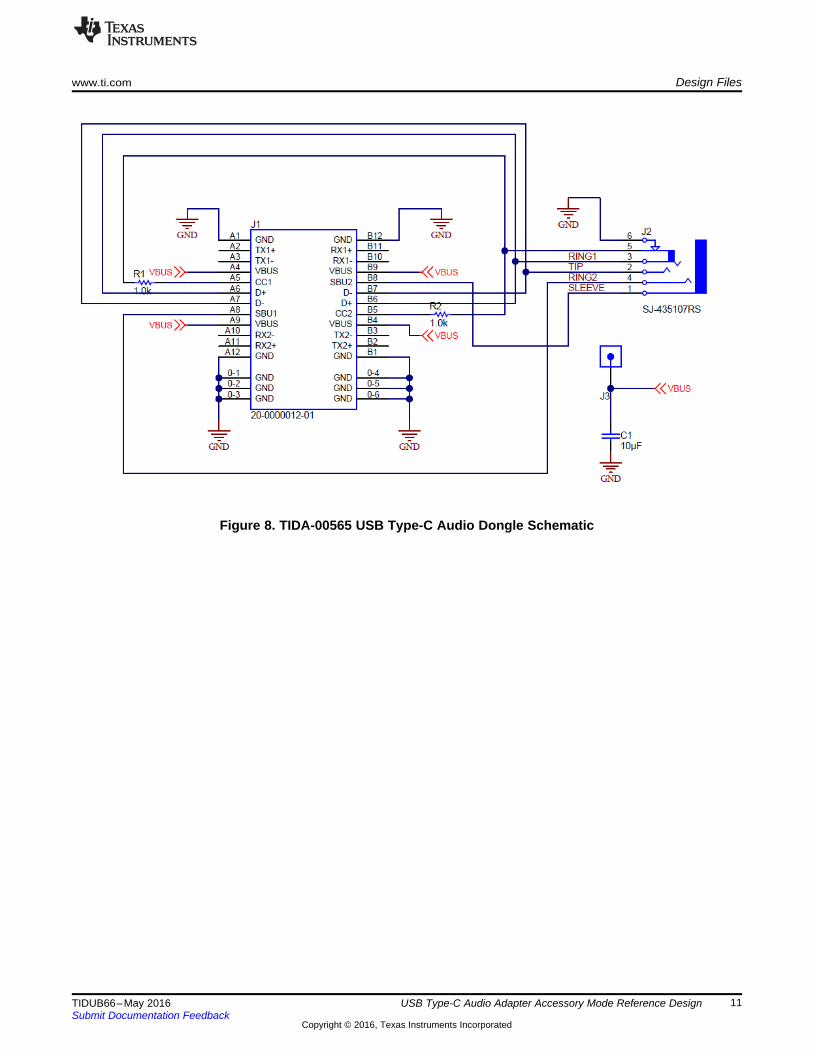
Figure 6 shows the TIDA-00565 power delivery schematic, Figure 7 shows the TIDA-00565 power pathschematic, and Figure 8 shows the TIDA-00565 USB Type-C audio dongle schematic.
Figure 6. TIDA-00565 Power Delivery Schematics

VIN1
VSENSE6
EN8
RT10
GND3
COMP7
PH2
BOOT9
PAD11
GND4
GND5
U5
TPS54335DRCR
0.1µFC26
0.1µF
C20
100kR82
0.1µFC23
DNPC27
DNPC30
DNPR81
DNPR83 GND
GND
GNDGND
GND
GND
0.1µFC37
0.1µF
C31
100kR92
19.1kR94
0.1µFC34
DNPC38
DNPC41
DNPR93 GND
GND
GNDGND
GND
GND
0.1µFC48
0.1µF
C42
100kR102
0.1µFC45
DNPC49
DNPC52
DNPR101
DNPR103 GND
GND
GNDGND
GND
GND
22µFC46
22µFC47
GND
VIN1
VSENSE6
EN8
RT10
GND3
COMP7
PH2
BOOT9
PAD11
GND4
GND5
U6
TPS54335DRCRGND
VIN1
VSENSE6
EN8
RT10
GND3
COMP7
PH2
BOOT9
PAD11
GND4
GND5
U7
TPS54335DRCRGND
22µFC35
22µFC36
22µFC24
22µFC25
System_3V3
System_5V
HV_Source1
2
3
J5
32.4kR84
7.15kR104
SENSE1
GND4
POWER2
POWER3
GND5
SHIELD6
SHIELD7
SHIELD8
SHIELD9
J4
JPD1135-509-7F
External Power
GND
TP5
S3
1.00k
R27System_RESET
Tiva_5VSystem_5V
Tiva_3V3System_3V3
1 2
3 4
J7
10µFC33
10µFC22
10µFC44
DNPR91
J9
47.5kR97
47.5kR109
8.45kR95
100pFC39
2200pFC40
9.53kR108
91pFC50
1800pFC51
330pFC28
5600pFC29
2.74kR85
47.5kR88
System_3V3
System_5V
External Power
External Power
External Power
System_3V3
HV_Source
12V_VSENSE
12V_VSENSE
5V_VSENSE
5V_VSENSE
3V3_VSENSE
3V3_VSENSE
GND
10uH
L4
10uH
L3
10uH
L2
Design Files www.ti.com
10 TIDUB66–May 2016Submit Documentation Feedback
Copyright © 2016, Texas Instruments Incorporated
USB Type-C Audio Adapter Accessory Mode Reference Design
Figure 7. TIDA-00565 Power Path Schematic
www.ti.com Design Files
11TIDUB66–May 2016Submit Documentation Feedback
Copyright © 2016, Texas Instruments Incorporated
USB Type-C Audio Adapter Accessory Mode Reference Design
Figure 8. TIDA-00565 USB Type-C Audio Dongle Schematic

Design Files www.ti.com
12 TIDUB66–May 2016Submit Documentation Feedback
Copyright © 2016, Texas Instruments Incorporated
USB Type-C Audio Adapter Accessory Mode Reference Design
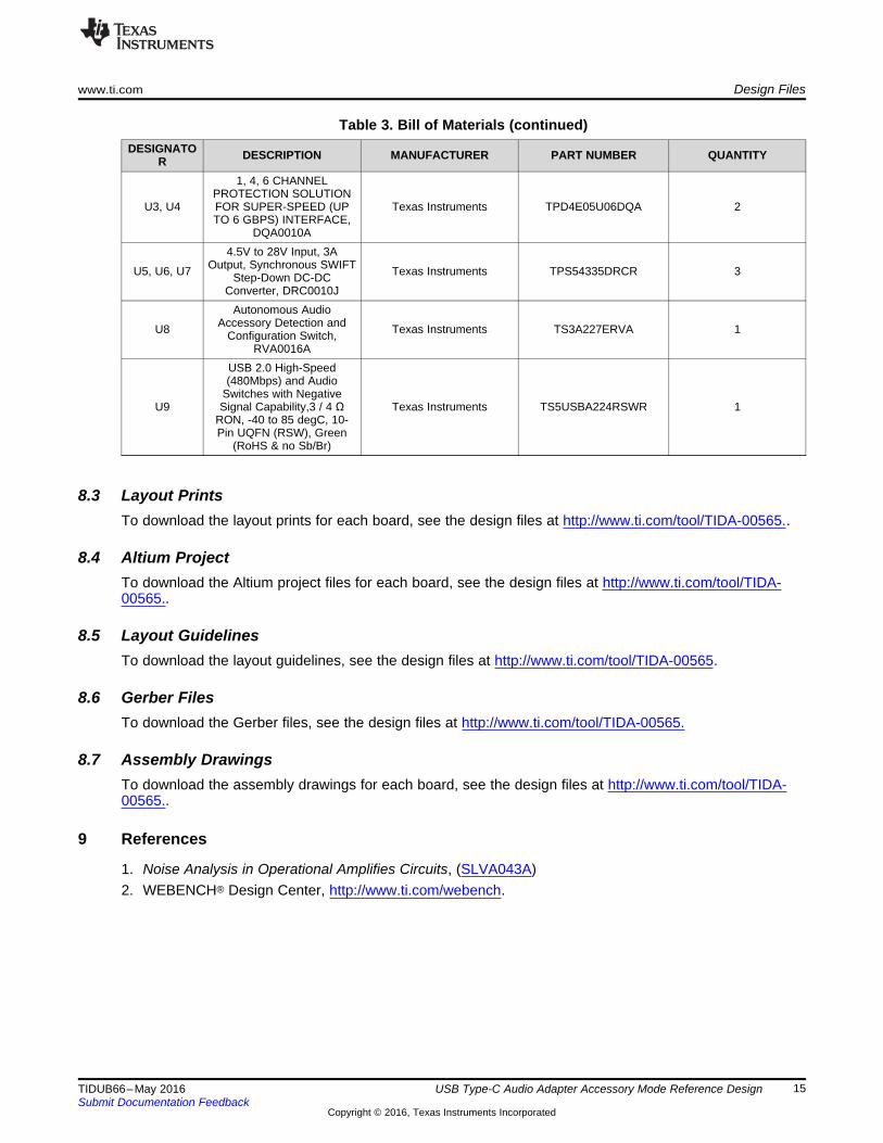
8.2 Bill of Materials (BOM)To download the bill of materials (BOM), see the design files at TIDA-00565..
Table 3. Bill of Materials
DESIGNATOR DESCRIPTION MANUFACTURER PART NUMBER QUANTITY
!PCB1 Printed Circuit Board Any TIDA-00565 1
C1, C4 CAP, CERM, 10 µF, 25 V,±20%, X5R, 0603 MuRata™ GRM188R61E106MA73 2
C2, C12 CAP, CERM, 0.1 µF, 10 V,±10%, X5R, 0201 Samsung™ CL03A104KP3NNNC 2
C3 CAP, CERM, 0.22 µF, 6.3 V,±20%, X5R, 0201 MuRata GRM033R60J224ME90 1
C5, C20,C23, C26,
C31,C34, C37,C42, C45,
C48
CAP, CERM, 0.1 µF, 50 V,±20%, C0G/NP0, 0402,
CAP, CERM, 0.1 uF, 50 V,±20%, C0G/NP0, 0402,
CAP, CERM, 0.1 uF, 50V,±20%, C0G/NP0, 0402,
CAP, CERM, 0.1 uF, 50V,±20%, C0G/NP0, 0402,
CAP, CERM, 0.1uF, 50 V,±20%, C0G/NP0, 0402,
CAP, CERM, 0.1uF, 50V,±20%, C0G/NP0, 0402,
CAP, CERM, 0.1 uF, 50V,±20%, C0G/NP0, 0402,
CAP, CERM, 0.1uF, 50V,±20%, C0G/NP0, 0402,
CAP, CERM, 0.1 uF, 50V,±20%, C0G/NP0, 0402,
CAP, CERM, 0.1 uF, 50 V,±20%, C0G/NP0, 0402
TDK® C1005X7R1H104M 10
C6 CAP, CERM, 1 µF, 35 V, ±10%, JB, 0402 TDK C1005JB1V105K050BC 1
C7–C10 CAP, CERM, 0.01 µF, 50 V,±10%, X7R, 0402 MuRata GRM155R71H103KA88D 4
C11 CAP, CERM, 22 µF, 10 V,±20%, X5R, 0603 MuRata GRM188R61A226ME15D 1
C13,C16–C18
CAP, CERM, 1 µF, 10 V,±20%, X5R, 0201 Samsung CL03A105MP3NSNC 4
C14 CAP, CERM, 10 µF, 10 V,±20%, X5R, 0402 Samsung CL05A106MP5NUNC 1
C15, C19 CAP, CERM, 220 pF, 25 V,±10%, X7R, 0201 MuRata GRM033R71E221KA01D 2
C21, C54 CAP, CERM, 1 µF, 6.3 V,±20%, X5R, 0402 MuRata GRM152R60J105ME15D 2
C22, C33,C44
CAP, CERM, 10 µF, 25 V,±10%, X5R, 0805 TDK C2012X5R1E106K125AB 3
C24, C25,C35,
C36, C46,C47
CAP, CERM, 22 µF, 35 V,±20%, X5R, 0805 TDK C2012X5R1V226M125AC 6
C27, C30,C38,
C41, C49,C52
CAP, CERM, 120 pF, 50 V,±5%, C0G/NP0, 0402 MuRata GRM1555C1H121JA01D 6
C28 CAP, CERM, 330 pF, 50 V,±5%, C0G/NP0, 0402 TDK C1005C0G1H331J 1
C29 CAP, CERM, 5600 pF, 50 V,±10%, X7R, 0402 MuRata 'GRM155R71H562KA88D 1

www.ti.com Design Files
13TIDUB66–May 2016Submit Documentation Feedback
Copyright © 2016, Texas Instruments Incorporated
USB Type-C Audio Adapter Accessory Mode Reference Design
Table 3. Bill of Materials (continued)DESIGNATO
R DESCRIPTION MANUFACTURER PART NUMBER QUANTITY
C32, C43 CAP, CERM, 0.1 µF, 6.3 V,±10%, X7R, 0402 MuRata GRM155R70J104KA01D 2
C39 CAP, CERM, 100 pF, 50 V,±10%, X7R, 0402 Yageo America™ CC0402KRX7R9BB101 1
C40 CAP, CERM, 2200 pF, 50 V,±10%, X5R, 0402 MuRata GRM155R61H222KA01D 1
C50 CAP, CERM, 91 pF, 50 V,±5%, C0G/NP0, 0402 MuRata GRM1555C1H910JA01D 1
C51 CAP, CERM, 1800 pF, 50 V,±10%, X7R, 0402 MuRata GRM1555C1H910JA01D 1
C53 CAP, CERM, 0.01 µF, 10 V,±10%, X5R, 0201 MuRata GRM155R71H182KA01D 1
D1 Diode, Schottky, 40 V, 3 A,SMA Diodes Inc. B340A-13-F 1
D2–D9 LED, White, SMD OSRAM™ LW QH8G-Q2S2-3K5L-1 8
FID1–FID4 Fiducial mark. There isnothing to buy or mount. N/A N/A 4
H1–H4Machine Screw, Round, #4-
40 x 1/4, Nylon, Philipspanhead
B&F Fastener Supply NY PMS 440 0025 PH 4
H5–H8 Standoff, Hex, 0.5"L #4-40Nylon Keystone™ 1902C 4
J1 Connector, Receptacle, USBType C, R/A, SMT Lintes Technology™ 20-0000016-01 1
J2, J3 Receptacle, 100 mil, 10×2,Gold, TH
Sullins ConnectorSolutions™ PPC102LFBN-RC 2
J4 Connector, DC Power Jack,R/A, 3 Pos, TH Foxconn™ JPD1135-509-7F 1
J5 Receptacle, 100 mil, 3×1,Gold, TH Sullins Connector Solutions PPPC031LFBN-RC 1
J6 Header, 100 mil, 2×1, Tin,TH Molex 90120-0122 1
J7 Header, 100 mil, 2×2, Tin,SMT Molex 15-91-2040 1
J8 Audio Jack, 3.5 mm, Stereo,R/A, SMT CUI Inc. SJ-43515TS-SMT-TR 1
L1 Ferrite Bead, 21 Ω at 100MHz, 6A, 0805 Taiyo Yuden™ FBMJ2125HM210NT 1
L2–L4 ABRACON™ ASPI-0630LR-100M-T15 3
Q1, Q2 MOSFET, N-CH, 30 V, 60 A,SON 3.3×3.3 mm Texas Instruments CSD17309Q3 2
Q3–Q10 Transistor, NPN, 50 V, 0.05A, SOT-323 Rohm DTC114EUAT106 8
R1 RES, 0.01 Ω, 1%, 0.25W,0805 Vishay-Dale™ WSL0805R0100FEA18 1
R2–R6, R10,R11,
R16–R19,R22, R23,R30–R32,R34–R41,R46–R48,R50, R51,R53, R54,
R56,R57–R69,
R71
RES, 0, 5%, 0.05 W, 0201 Panasonic ERJ-1GE0R00C 45

Design Files www.ti.com
14 TIDUB66–May 2016Submit Documentation Feedback
Copyright © 2016, Texas Instruments Incorporated
USB Type-C Audio Adapter Accessory Mode Reference Design
Table 3. Bill of Materials (continued)DESIGNATO
R DESCRIPTION MANUFACTURER PART NUMBER QUANTITY
5 RES, 3.3 k, 5%, 0.063 W,0402 Vishay-Dale CRCW04023K30JNED 4
R12–15, R27 RES, 1.00 k, 1%, 0.05 W,0201 Vishay-Dale CRCW02011K00FKED 5
R20, R75,R76,
R79, R80
RES, 3.83 k, 1%, 0.05 W,0201 Vishay-Dale CRCW02013K83FKED 7
R21,R24–R26,R29, R33,
R70
RES, 100 k, 1%, 0.05 W,0201 Vishay-Dale CRCW0201100KFKED 1
R28 RES, 15.0 k, 1%, 0.063 W,0402 Vishay-Dale CRCW040215K0FKED 8
R72–R74,R86, R87,R89, R90,
R96
RES, 560, 5%, 0.063 W,0402 Vishay-Dale CRCW0402560RJNED 2
R77, R78 RES, 9.09 k, 1%, 0.05 W,0201 Vishay-Dale CRCW02019K09FKED 3
R81, R91,R101
RES, 220 k, 5%, 0.063 W,0402 Vishay-Dale CRCW0402220KJNED 3
R82, R92,R102
RES, 100 k, 1%, 0.063 W,0402 Vishay-Dale CRCW0402100KFKED 3
R83, R93,R103
RES, 43.2 k, 1%, 0.063 W,0402 Vishay-Dale CRCW040243K2FKED 3
R84 RES, 32.4 k, 1%, 0.063 W,0402 Vishay-Dale CRCW040232K4FKED 1
R85 RES, 2.74 k, 1%, 0.063 W,0402 Vishay-Dale CRCW04022K74FKED 1
R88, R97,R109
RES, 47.5 k, 1%, 0.063 W,0402 Vishay-Dale CRCW040247K5FKED 3
R94 RES, 19.1 k, 1%, 0.063 W,0402 Vishay-Dale CRCW040219K1FKED 1
R95 RES, 8.45 k, 1%, 0.063 W,0402 Vishay-Dale CRCW04028K45FKED 1
R98, R105 RES, 4.70 k, 1%, 0.1 W,0402 Panasonic ERJ-2RKF4701X 2
R104 RES, 7.15 k, 1%, 0.063 W,0402 Vishay-Dale CRCW04027K15FKED 1
R106, R107 RES, 10.0 k, 1%, 0.1 W,0402 Vishay-Dale ERJ-2PKF1002X 2
R108 RES, 9.53 k, 1%, 0.063 W,0402 Panasonic CRCW04029K53FKED 1
S1 DIP Switch, SPST 4Pos,Slide, SMT C&K Components™ TDA04H0SB1 1
S3 SWITCH TACTILE SPST-NO 0.05A 12V
Omron ElectronicComponents™ B3U-1000P 1
TP1–TP5 Test Point, Miniature, SMT Keystone 5019 5
U13V, 8Mbit, Serial Flash
Memory with Dual and QualSPI, SOIC-8
Winbond® W25Q80DVSNIG 1
U2 TPS65982 PreviewSpecification, ZQZ0096A Texas Instruments TPS65982AAZQZR 1
www.ti.com Design Files
15TIDUB66–May 2016Submit Documentation Feedback
Copyright © 2016, Texas Instruments Incorporated
USB Type-C Audio Adapter Accessory Mode Reference Design
Table 3. Bill of Materials (continued)DESIGNATO
R DESCRIPTION MANUFACTURER PART NUMBER QUANTITY
U3, U4
1, 4, 6 CHANNELPROTECTION SOLUTIONFOR SUPER-SPEED (UPTO 6 GBPS) INTERFACE,
DQA0010A
Texas Instruments TPD4E05U06DQA 2
U5, U6, U7
4.5V to 28V Input, 3AOutput, Synchronous SWIFT
Step-Down DC-DCConverter, DRC0010J
Texas Instruments TPS54335DRCR 3
U8
Autonomous AudioAccessory Detection and
Configuration Switch,RVA0016A
Texas Instruments TS3A227ERVA 1
U9
USB 2.0 High-Speed(480Mbps) and Audio
Switches with NegativeSignal Capability,3 / 4 Ω
RON, -40 to 85 degC, 10-Pin UQFN (RSW), Green
(RoHS & no Sb/Br)
Texas Instruments TS5USBA224RSWR 1
8.3 Layout PrintsTo download the layout prints for each board, see the design files at http://www.ti.com/tool/TIDA-00565..
8.4 Altium ProjectTo download the Altium project files for each board, see the design files at http://www.ti.com/tool/TIDA-00565..
8.5 Layout GuidelinesTo download the layout guidelines, see the design files at http://www.ti.com/tool/TIDA-00565.
8.6 Gerber FilesTo download the Gerber files, see the design files at http://www.ti.com/tool/TIDA-00565.
8.7 Assembly DrawingsTo download the assembly drawings for each board, see the design files at http://www.ti.com/tool/TIDA-00565..
9 References
1. Noise Analysis in Operational Amplifies Circuits, (SLVA043A)2. WEBENCH® Design Center, http://www.ti.com/webench.
www.ti.com
16 TIDUB66–May 2016Submit Documentation Feedback
Copyright © 2016, Texas Instruments Incorporated
Appendix A
A.1 TS5USBA224The TS5USBA224 USB 2.0 and audio switch is used to multiplex between the USB 2.0 data and analogaudio. The switch is a FET-based switch, which is optimized with low On-resistance to maintain signalintegrity. The USB 2.0 path has a bandwidth of up to 650 MHz signals. The audio path features a THD+Nof less than 0.05% and includes shunt resistors to reduce clicks and pops that may be heard when theaudio switch is selected by dissipating residual charge that could be on the audio path. The TS5USBA224switch is used to protect other components on the D+ and D- lines from analog audio signals that swing toa negative voltage. Figure 9 shows the functional block diagram of the TS5USBA224.

VBUS
VAUDIO
D+/R
D–/L
D+
D–
R
L
Control LogicASEL
Rshunt
Rshunt
Rpd1 Rpd2
www.ti.com TS5USBA224
17TIDUB66–May 2016Submit Documentation Feedback
Copyright © 2016, Texas Instruments Incorporated
Figure 9. Functional Block Diagram of the TSUSBA224

R M GL
16-2 kΩ
16-2 kΩ
600-4kΩ
OMTP
4-pole TRRS
Tip Ring1 SleeveRing2
R G ML
16-2 kΩ
16-2 kΩ
600-4kΩ
Standard
Tip Ring Sleeve
3-pole TRS
R GL
16-2 kΩ
16-2 kΩ
TRS
PHYSICAL CONNECTOR INTERNAL IMPEDANCE NETWORK PIN NAME CONFIGURATION
Tip Audio Left
Ring Audio Right
Sleeve Ground
Tip Audio Left
Ring1 Audio Right
Ring2 Ground
Sleeve Microphone
Tip Audio Left
Ring1 Audio Right
Ring2 Microphone
Sleeve Ground
TS3A227E www.ti.com
18 TIDUB66–May 2016Submit Documentation Feedback
Copyright © 2016, Texas Instruments Incorporated
A.2 TS3A227EThe TS3A227E audio jack switch is used to automatically route the MIC and GND signals appropriately.There are three types of audio jacks that may be inserted into the 3.5 mm audio jack. One of the threeaudio jacks is a 3-pole jack, containing left and right audio, and GND. Two of the three audio jacks are 4-pole jacks, containing the left and right audio, MIC, and GND. For the 4-pole jacks, the MIC and GND maypotentially be swapped, depending on the manufacture of the audio jack. Thus, the TS3A227E detects thecorrect location of both MIC and GND on the 4-pole audio jack and routes the GND properly to GND andMIC to the desired location.
Figure 10. Functional Block Diagram of the TS3A227E

Digital Core
Power Management and Supervisors
Port Data Multiplexer
NMOS
External FET Control and Sense
2
2
2
2
2
2
3
3
4
2
9
2
2
2
C_USB_TP/TN
C_USB_BP/BN
C_SBU1/2
C_CC1
C_CC2
VBUS
PP_5V0
VIN_3V3
RESETZ
MRESET
VOUT_3V3
LDO_3V3
LDO_1V8A
LDO_1V8D
LDO_BMC
BUSPOWERZ
R_OSC
GPIO1-9
I2C_SDA/SCL/IRQ1Z
I2C_SDA/SCL/IRQ2Z
SPI_MOSI/MISO/SSZ/CLK
SWD_DATA/CLK
I2C_ADDR
PP_HV
PP_CABLE 3A
3A
600mA
SENSEP SENSEN
GND
2DEBUG_CTL1/2
UART_RX/TX
LSX_R2P/P2R
AUX_P/N
USB_RP_P/N
DEBUG1/2
DEBUG3/4
RPD_G1
RPD_G2
PP_EXT
HV_GATE1 HV_GATE2
VDDIO
Cable/Device
Detect,
and
USB-PD Phy
Cable Power,
www.ti.com TPS65982
19TIDUB66–May 2016Submit Documentation Feedback
Copyright © 2016, Texas Instruments Incorporated
A.3 TPS65982The TPS65982 function as a power delivery IC for USB Type-C. In the case of this USB Type-C analogaudio TI Design, the TPS65982 is used for its accessory detection feature on the CC1 and CC2 pins ofthe USB Type-C connector. TI offers other smaller products that soley provide the accessory detectionfeature such as the TUSB32X series of devices. After the TPS65982 detects the impedance of Ra (800 Ω< Ra < 1.2 kΩ), a GPIO on the TPS65982 configures the TS5USBA224 to the audio pathway. If theTPS65982 detects the impedance not equal to Ra, the GPIO configures the TS5USBA224 to the USBpathway. When a non-audio peripheral is attached to the USB-C, the TPS65982 performs its full functionas a power delivery IC. Figure 11 shows the functional block diagram of the TPS65982.
Figure 11. Functional Block Diagram of the TPS65982

www.ti.com
20 TIDUB66–May 2016Submit Documentation Feedback
Copyright © 2016, Texas Instruments Incorporated
Appendix B
B.1 Getting Started Firmware
B.1.1 TPS6598x Configuration Tool From TI.com
B.1.1.1 Downloading the TPS6598x Configuration Tool1. Follow the TPS6598x configuration tool link from TI.com, as shown in Figure 12.
Figure 12. TPS6598x Configuration Tool Download Page
2. Log in to your myTI account, as shown in Figure 13.
Figure 13. My TI Account Login Screen
3. Fill out the TI request form, as shown in Figure 14.

www.ti.com Getting Started Firmware
21TIDUB66–May 2016Submit Documentation Feedback
Copyright © 2016, Texas Instruments Incorporated
Figure 14. TI Request Screen
4. Once approved, download the configuration tool, as shown in Figure 15.
Figure 15. TI Request Approval Screen
5. Save the file, as shown in Figure 16.

Getting Started Firmware www.ti.com
22 TIDUB66–May 2016Submit Documentation Feedback
Copyright © 2016, Texas Instruments Incorporated
Figure 16. TPS6598x Configuration Tool Download
6. Extract all files, as shown in Figure 17.
Figure 17. TPS6598x Configuration Image
B.1.1.2 Launching the TPS6598x Configuration ToolThe TPS6598x Configuration Tool is implemented using a combination of html and JavaScript files. Usersare able to execute the tool on nearly any PC platform using the web browser of their choice. To uselaunch the tool, de-archive the package files to any desired file system location and browse to theindex.html file located at:
<install_dir>\TPS6598x_WebTool_<version>\javascript\index.html
On a Windows® platform:1. Navigate to the file within the windows.2. Right-click and select open with.3. Or, launch a web browser.4. Enter as a file url: file:///<install_dir>/TPS6598x_WebTool_<version>/javascript/index.html.
The example URL (tested using the Chrome browser):
file:///C:TPS65982_WebTool_vs.TPS6598x_WebTool_vs.29/javascript/index.html
For more information about the TPS6598x, see the TPS65x Configuration Tool User Guide (SLVUAI9A).

www.ti.com Getting Started Firmware
23TIDUB66–May 2016Submit Documentation Feedback
Copyright © 2016, Texas Instruments Incorporated
B.1.1.3 Using the Configuration Tool to Set Up the TPS65982 for Audio Accessory Detection Mode1. Click load defaults
Figure 18 shows the TPS6598x configuration tool screen home screen.
Figure 18. TPS6598x Configuration Tool Screen Home Screen
2. Select the second option TPS65982 Dual-Role Port.3. Select Power Agnostic.4. Select Prefers Data Source.5. Click Ok.6. Select GPIO Mappings from the menu on the left.
Figure 19 shows the TPS6598x configuration tool GPIO mappings screen shot 1.
Figure 19. TPS6598x Configuration Tool GPIO Mappings Screen Shot 1
7. Navigate to GPIO 6 using the scroll bar.Figure 20 shows the TPS6598x configuration tool GPIO mappings screen shot 2.

Getting Started Firmware www.ti.com
24 TIDUB66–May 2016Submit Documentation Feedback
Copyright © 2016, Texas Instruments Incorporated
Figure 20. TPS6598x Configuration Tool GPIO Mappings Screen Shot 2
8. To configure the GPIO 6 event, click the drop down menu on the right.9. Select Audio Enable Event.
Figure 21 shows the TPS6598x configuration tool GPIO screen shot 3.
Figure 21. TPS6598x Configuration Tool GPIO Screen Shot 3
10. Click Save in the upper right corner to create the files, as shown in Figure 22 .
Figure 22. TPS6598x Configuration Tool Save

www.ti.com Getting Started Firmware
25TIDUB66–May 2016Submit Documentation Feedback
Copyright © 2016, Texas Instruments Incorporated
B.1.2 Flashing the TPS65982 With the Audio Accessory Adapter Detection ConfigurationDownload the TIDA-00565-Flash-Imange.bin file from TI.com, or follow the configuration tool instructionsbelow.
You may flash the TPS65982 over a SPI interface through the J2 and J3 connectors on the TIDA00565board.
Figure 23 and shows the TIDA-00565 pin out assignments for SPI communication. shows...
Figure 23. TIDA-00565 Pin Out Assignments for SPI Communication
The following procedure describes how to flash the WQ2580 IC of the TPS65982-EVM with firmware(1024kB .bin file) using an Aardvark SPI Programmer by connecting to the SPI pins of header J2.
The firmware file that must be used is TIDA-00565-Flash-Image.bin.
Writing a flash image using an Aardvark SPI Programmer:In the following sections, there are images indicating additional information. Use the legend that appearsbefore the image to understand what image corresponds to what action.
Getting Started Firmware www.ti.com
26 TIDUB66–May 2016Submit Documentation Feedback
Copyright © 2016, Texas Instruments Incorporated
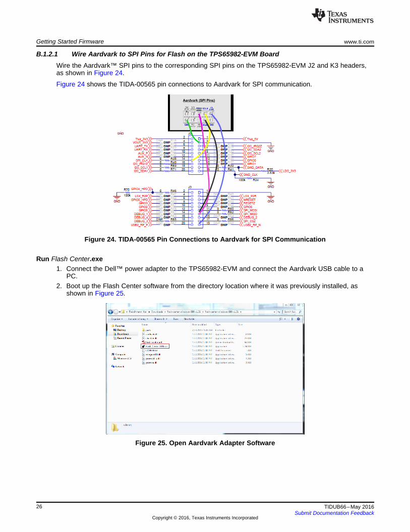
B.1.2.1 Wire Aardvark to SPI Pins for Flash on the TPS65982-EVM BoardWire the Aardvark™ SPI pins to the corresponding SPI pins on the TPS65982-EVM J2 and K3 headers,as shown in Figure 24.
Figure 24 shows the TIDA-00565 pin connections to Aardvark for SPI communication.
Figure 24. TIDA-00565 Pin Connections to Aardvark for SPI Communication
Run Flash Center.exe1. Connect the Dell™ power adapter to the TPS65982-EVM and connect the Aardvark USB cable to a
PC.2. Boot up the Flash Center software from the directory location where it was previously installed, as
shown in Figure 25.
Figure 25. Open Aardvark Adapter Software

www.ti.com Getting Started Firmware
27TIDUB66–May 2016Submit Documentation Feedback
Copyright © 2016, Texas Instruments Incorporated
B.1.2.2 Add AdapterThe Flash Center application uses a variety of adapters. To use the Aardvark adapter, you must add it.1. To add the adapter, click Add Adapters.2. Select the Aardvark adapter, as shown in Figure 25.
NOTE: The Flash Center should automatically detect the Aardvark when adding the adapter. If theFlash Center does not automatically detect the Aardvark adapter, download the Aardvarkdrivers from Total Phase™, and follow the installation prompts.
B.1.2.3 Choose Target (Device Type)For the Flash Center to flash the TPS65982-EVM, the user must select the proper flash or device type.
Click the Choose Target button to select the Target Device type. As shown in Figure 26, the TargetDevice type in this case is SPI Flash→Winbond/NexFlash→W25Q80.
Figure 26. Aardvark Adapter Sofrware Screen Shot 1
B.1.2.4 Load Binary File1. Select load file to load the binary file that will go onto the TPS65982-EVM.2. Proceed to the directory where the binary file has been saved.3. Click open after the binary file is selected.4. If successful, the data section of the Flash Center will be full of values.
Figure 27 shows the Aardvark adapter software screen shot 2.

Getting Started Firmware www.ti.com
28 TIDUB66–May 2016Submit Documentation Feedback
Copyright © 2016, Texas Instruments Incorporated
Figure 27. Aardvark Adapter Software Screen Shot 2
Figure 28 shows the Aardvark adapter software screen shot 3.
Figure 28. Aardvark Adapter Software Screen Shot 3
Figure 29 shows the Aardvark adapter software screen shot 4.
Figure 29. Aardvark Adapter Software Screen Shot 4
Figure 30 shows the Aardvark adapter software screen shot 6.
Figure 30. Aardvark Adapter Software Screen Shot 5

www.ti.com Getting Started Firmware
29TIDUB66–May 2016Submit Documentation Feedback
Copyright © 2016, Texas Instruments Incorporated
B.1.2.5 Verify (Optional)To confirm that the loaded binary image matches the firmware installed on the TPS65982-EVM, click theverify button and see if it reports a success. Figure 31 shows the Aardvark adapter software screen shot6.
Figure 31. Aardvark Adapter Software Screen Shot 6
Figure 32 shows the Aardvark adapter software screen shot 7.
Figure 32. Aardvark Adapter Software Screen Shot 7
Figure 33 shows the Aardvark adapter software screen shot 8.

Getting Started Firmware www.ti.com
30 TIDUB66–May 2016Submit Documentation Feedback
Copyright © 2016, Texas Instruments Incorporated
Figure 33. Aardvark Adapter Software Screen Shot 8
Figure 34 shows the THD + N audio precision test setup screen shot.

www.ti.com Getting Started Firmware
31TIDUB66–May 2016Submit Documentation Feedback
Copyright © 2016, Texas Instruments Incorporated
Figure 34. THD + N Audio Precision Test Setup Screen Shot

IMPORTANT NOTICE FOR TI REFERENCE DESIGNS
Texas Instruments Incorporated (‘TI”) reference designs are solely intended to assist designers (“Designer(s)”) who are developing systemsthat incorporate TI products. TI has not conducted any testing other than that specifically described in the published documentation for aparticular reference design.TI’s provision of reference designs and any other technical, applications or design advice, quality characterization, reliability data or otherinformation or services does not expand or otherwise alter TI’s applicable published warranties or warranty disclaimers for TI products, andno additional obligations or liabilities arise from TI providing such reference designs or other items.TI reserves the right to make corrections, enhancements, improvements and other changes to its reference designs and other items.Designer understands and agrees that Designer remains responsible for using its independent analysis, evaluation and judgment indesigning Designer’s systems and products, and has full and exclusive responsibility to assure the safety of its products and compliance ofits products (and of all TI products used in or for such Designer’s products) with all applicable regulations, laws and other applicablerequirements. Designer represents that, with respect to its applications, it has all the necessary expertise to create and implementsafeguards that (1) anticipate dangerous consequences of failures, (2) monitor failures and their consequences, and (3) lessen thelikelihood of failures that might cause harm and take appropriate actions. Designer agrees that prior to using or distributing any systemsthat include TI products, Designer will thoroughly test such systems and the functionality of such TI products as used in such systems.Designer may not use any TI products in life-critical medical equipment unless authorized officers of the parties have executed a specialcontract specifically governing such use. Life-critical medical equipment is medical equipment where failure of such equipment would causeserious bodily injury or death (e.g., life support, pacemakers, defibrillators, heart pumps, neurostimulators, and implantables). Suchequipment includes, without limitation, all medical devices identified by the U.S. Food and Drug Administration as Class III devices andequivalent classifications outside the U.S.Designers are authorized to use, copy and modify any individual TI reference design only in connection with the development of endproducts that include the TI product(s) identified in that reference design. HOWEVER, NO OTHER LICENSE, EXPRESS OR IMPLIED, BYESTOPPEL OR OTHERWISE TO ANY OTHER TI INTELLECTUAL PROPERTY RIGHT, AND NO LICENSE TO ANY TECHNOLOGY ORINTELLECTUAL PROPERTY RIGHT OF TI OR ANY THIRD PARTY IS GRANTED HEREIN, including but not limited to any patent right,copyright, mask work right, or other intellectual property right relating to any combination, machine, or process in which TI products orservices are used. Information published by TI regarding third-party products or services does not constitute a license to use such productsor services, or a warranty or endorsement thereof. Use of the reference design or other items described above may require a license from athird party under the patents or other intellectual property of the third party, or a license from TI under the patents or other intellectualproperty of TI.TI REFERENCE DESIGNS AND OTHER ITEMS DESCRIBED ABOVE ARE PROVIDED “AS IS” AND WITH ALL FAULTS. TI DISCLAIMSALL OTHER WARRANTIES OR REPRESENTATIONS, EXPRESS OR IMPLIED, REGARDING THE REFERENCE DESIGNS OR USE OFTHE REFERENCE DESIGNS, INCLUDING BUT NOT LIMITED TO ACCURACY OR COMPLETENESS, TITLE, ANY EPIDEMIC FAILUREWARRANTY AND ANY IMPLIED WARRANTIES OF MERCHANTABILITY, FITNESS FOR A PARTICULAR PURPOSE, AND NON-INFRINGEMENT OF ANY THIRD PARTY INTELLECTUAL PROPERTY RIGHTS.TI SHALL NOT BE LIABLE FOR AND SHALL NOT DEFEND OR INDEMNIFY DESIGNERS AGAINST ANY CLAIM, INCLUDING BUT NOTLIMITED TO ANY INFRINGEMENT CLAIM THAT RELATES TO OR IS BASED ON ANY COMBINATION OF PRODUCTS ASDESCRIBED IN A TI REFERENCE DESIGN OR OTHERWISE. IN NO EVENT SHALL TI BE LIABLE FOR ANY ACTUAL, DIRECT,SPECIAL, COLLATERAL, INDIRECT, PUNITIVE, INCIDENTAL, CONSEQUENTIAL OR EXEMPLARY DAMAGES IN CONNECTION WITHOR ARISING OUT OF THE REFERENCE DESIGNS OR USE OF THE REFERENCE DESIGNS, AND REGARDLESS OF WHETHER TIHAS BEEN ADVISED OF THE POSSIBILITY OF SUCH DAMAGES.TI’s standard terms of sale for semiconductor products (http://www.ti.com/sc/docs/stdterms.htm) apply to the sale of packaged integratedcircuit products. Additional terms may apply to the use or sale of other types of TI products and services.Designer will fully indemnify TI and its representatives against any damages, costs, losses, and/or liabilities arising out of Designer’s non-compliance with the terms and provisions of this Notice.IMPORTANT NOTICE
Mailing Address: Texas Instruments, Post Office Box 655303, Dallas, Texas 75265Copyright © 2016, Texas Instruments Incorporated