3. COMMUNICATION EQUIPMENT SELECTION … 3.9 Vehicular Adapter (Portable Radios) Vehicular adapter...
41
13 3. COMMUNICATION EQUIPMENT SELECTION FACTORS This section provides a discussion of 14 selection factors that are recommended for consideration by the emergency first responder community when selecting and purchasing communications equipment that can be used in conjunction with chemical and biological protective clothing and respiratory equipment. These factors were compiled by a panel of scientists and engineers who have multiple years of experience in communication equipment, domestic preparedness, emergency and public service communications, and identification of emergency first responder needs. The factors have also been shared with the emergency first responder community in order to get their thoughts and comments. It is anticipated that, as additional input is received from the emergency first responder community, additional factors may be added or existing factors may be modified. These factors were developed so that communications equipment could be compared and contrasted in order to assist with the selection and purchase of the most appropriate equipment. It is important to note that the evaluation conducted using the 14 selection factors was based solely upon vendor- supplied data and no independent evaluation of equipment was conducted in the development of this guide. The vendor-supplied data can be found in its entirety in Volume II. Prior to discussing each of the selection factors, it is important to note that although weight was considered an important selection factor for several of the other guides, weight was not included as a selection factor for communication equipment. By definition, a portable radio is light (< 2 lb), a mobile radio is attached to a vehicle (therefore weight is not critical), and repeaters are generally operated at a fixed location. The results of the evaluation of the communication equipment against the 14 selection factors are provided in section 4. The remainder of this section defines each of the selection factors. 3.1 Maximum Transmitter Output Power The transmitter output power refers to the maximum output power of the transmitter. For portable radios, too high an output power leads to a shortened battery use cycle (the time between battery recharging or replacing), or too low output can put the life of the responder operating the radio in jeopardy as the signal may not be able to be picked up by a repeater or another receiver. The above limitations do not apply to mobile radios or repeaters since they have a higher output and an external power source. 3.2 Secure Communications Compatibility Secure communications is the ability to encrypt and decrypt communications signals. Once properly encrypted, the communication equipment can transmit any signal.
Transcript of 3. COMMUNICATION EQUIPMENT SELECTION … 3.9 Vehicular Adapter (Portable Radios) Vehicular adapter...

13
3. COMMUNICATION EQUIPMENT SELECTION FACTORS
This section provides a discussion of 14 selection factors that are recommended for considerationby the emergency first responder community when selecting and purchasing communicationsequipment that can be used in conjunction with chemical and biological protective clothing andrespiratory equipment. These factors were compiled by a panel of scientists and engineers whohave multiple years of experience in communication equipment, domestic preparedness,emergency and public service communications, and identification of emergency first responderneeds. The factors have also been shared with the emergency first responder community in orderto get their thoughts and comments.
It is anticipated that, as additional input is received from the emergency first respondercommunity, additional factors may be added or existing factors may be modified. These factorswere developed so that communications equipment could be compared and contrasted in order toassist with the selection and purchase of the most appropriate equipment. It is important to notethat the evaluation conducted using the 14 selection factors was based solely upon vendor-supplied data and no independent evaluation of equipment was conducted in the development ofthis guide. The vendor-supplied data can be found in its entirety in Volume II.
Prior to discussing each of the selection factors, it is important to note that although weight wasconsidered an important selection factor for several of the other guides, weight was not includedas a selection factor for communication equipment. By definition, a portable radio is light (< 2 lb), a mobile radio is attached to a vehicle (therefore weight is not critical), and repeaters aregenerally operated at a fixed location.
The results of the evaluation of the communication equipment against the 14 selection factors areprovided in section 4. The remainder of this section defines each of the selection factors.
3.1 Maximum Transmitter Output Power
The transmitter output power refers to the maximum output power of the transmitter. Forportable radios, too high an output power leads to a shortened battery use cycle (the timebetween battery recharging or replacing), or too low output can put the life of the responderoperating the radio in jeopardy as the signal may not be able to be picked up by a repeater oranother receiver.
The above limitations do not apply to mobile radios or repeaters since they have a higher outputand an external power source.
3.2 Secure Communications Compatibility
Secure communications is the ability to encrypt and decrypt communications signals. Onceproperly encrypted, the communication equipment can transmit any signal.

14
3.3 Programmability
This selection factor defines how restrictive the radio programming is for the communicationsequipment. Programming communications equipment focuses primarily on the ability to add ordelete channels. Depending on the equipment, the ability to program or reprogram a radio maybe limited to authorized personnel and/or vendors. The equipment may be able to beprogrammed by the end user as well.
3.4 User Capability
User capability refers to the ability of the communication system to simultaneously supportdifferent types of users (e.g., fire, EMS, Command, and law enforcement). An “unlimitedcapability” refers to the ability of the equipment and/or system to support all users without anyrestrictions whatsoever. A “fixed capability” refers to a system that allows communications onlywithin each group, with Command Officers, and with other groups via a “shared mutual aid”channel. “Restrictive capability” refers to a system that allows users to communicate only withothers within their own user group and to Command Officers. A Command Officer cancommunicate with other Command Officers as well as all the user groups in the chain ofcommand.
3.5 Line of Sight
Line of sight refers to the distance that transmissions can occur in a clear area (no obstructionssuch as skyscrapers, forests, etc.) without a repeater.
3.6 Power Requirements
Power requirements indicate whether specific equipment can operate on a battery and/or acelectrical power. Since power requirements are inherently different for portable andmobile/repeater equipment items, separate selection factors for these equipment items arepresented.
3.7 Battery Life
Battery life is the ability of the portable radio equipped with an approved battery to operate atmaximum transmitter power for an 8 h duty shift when used in a 5/5/90 operating mode (5 % ofthe time transmitting, 5 % of the time receiving with the squelch being broken, 90 % of the timereceiving with the squelch not being broken––“standby”). To squelch is the ability to silence theradio in the absence of a desired incoming radio signal. This selection factor is only relevant forportable radios.
3.8 Battery Locking Ability
Battery locking ability considers how securely the battery is attached to the radio. This selectionfactor is only relevant for portable radios.
15
3.9 Vehicular Adapter (Portable Radios)
Vehicular adapter refers to whether the portable radio has an optional vehicular adapteraccessory. The vehicular adapter accessory allows the portable radio to act like a mobile radio.
3.10 Digital Communications Compatibility
Digital communications compatibility refers to whether the radio is capable of digitalcommunication with or without an adapter (a manufacturer or third party supplied moduleinstalled in the radio that permits operation on a digital communication system).
3.11 Durability
The durability of a piece of equipment describes the ruggedness of the equipment (i.e., can theequipment be dropped from several feet or submersed in water and still operate).
3.12 Unit Cost
Unit cost is the cost of the radio equipment, including the cost of all support equipment andconsumables. This factor, in conjunction with other selection factors, can help the user decide ifa radio will be deemed suitable for disposal after use, suitable for special uses only, or suitablefor all uses.
3.13 Operator Skill Requirements
Operator skill level refers to the skill level and training required for the operation of theequipment.
3.14 Training Requirements
Training requirements are the amount of instruction time required for the operator to becomeproficient in the operation of the instrument. For example, higher-end equipment such as arepeater requires more in-depth training than a portable radio; therefore, this selection factor hasdifferent criteria for portable and mobile/repeater equipment items.
Details on the manner in which the selection factors were used to assess the equipment arepresented in table 3–1.

16
Table 3-1. Selection factor key for communication equipmentFebruary 2001
Max
imum
Tra
nsm
itter
Pow
er O
utpu
t Sec
ure
Comm
unic
atio
ns
Compa
tibili
ty
Prog
ram
mab
ility
User C
apab
ility
Line
of S
ight
Power
Req
uire
men
ts
(Por
tabl
e)
(Por
tabl
e)
(Por
tabl
e)
(Por
tabl
e)
Power
Req
uire
men
ts
(Mob
ile a
nd R
epea
ter)
Batte
ry L
ife (P
orta
ble)
Batte
ry L
ocki
ng A
bilit
y
Vehic
ular
Ada
pter
Digita
l Com
mun
icat
ions
Compa
tibili
ty
Durab
ility
Unit C
ost
Ope
rato
r Ski
ll Le
vel
Trai
ning
Req
uire
men
tsTr
aini
ng R
equi
rem
ents
(Mob
ile a
nd R
epea
ter)
Power output of 3 W to 6 W
Capable of secure transmissions without an accessory
Can be programmed/ reprogrammed by authorized personnel
Unlimited capability
Transmission can travel 10 miles or more
Operates off battery pack, external dc, or ac adapter
Uses 12 V dc to 15 V dc
Equal to or greater than 8 h
Battery securely locked into place on the radio and cannot be dislodged by bumping or dropping
Has vehicle adapter (with built-in amplifier) that connects to vehicle's electrical system and external antenna
Capable of digital transmissions without an adaptor
Designed for rugged use and is submersible in water
Less than or equal to $500 per unit
No special skills or training required
No special training required
No special training required
Operates off battery pack or external dc adapter
Power output of more than 1.5 W but less than 3 W
Capable of secure transmissions with an accessory
Can be programmed/ reprogrammed by vendor only
Fixed capability
Transmission can travel 5 miles to 10 miles
Operates off battery pack or ac adapter
Uses 120/220 V ac
Greater than 4 h but less than 8 h
Capable of digital transmissions with an adaptor
Designed for rugged use but is not submersible in water
Greater than $500 but less than $1000 per unit
No special skills but some training required
Less than 60 min training required
Less than 8 h training required
Power output of less than 1.5 W
Not capable of secure transmissions
Can be programmed/ reprogrammed by the end user
Restrictive capability
Transmission can travel less than 5 miles
Operates off battery pack only
Uses voltage other than standard 12 V dc to 15 V dc or 110/220 V ac
Less than 4 hBattery not locked into place
Does not have optional vehicle adapter
Not capable of digitaltransmissions
Designed for standard use only
Greater than $1000 per unit
Technical background required to operate equipment
More than 60 min training required
More than 8 h training required
The gray cells designate that the symbol is not applicable for the selection factor.A duplicate of this table is provided for quick reference (as Table 4-12).

17
4. COMMUNICATION EQUIPMENT EVALUATION
An extensive market survey was conducted to identify commercially available communicationequipment. The market survey, which included the identification of new equipment andinteraction with numerous equipment vendors, identified 181 different communicationequipment items. Section 4, of this volume, documents the results of evaluating each equipmentitem versus the 14 selection factors identified in sec. 3. Section 4.1 defines the equipment usagecategories and sec. 4.2 discusses the evaluation results. Volume II of this guide provides detailsof the market survey, as well as data on each piece of equipment.
4.1 Equipment Categories
To display the evaluation results in a meaningful format, the communication equipment wasgrouped into four categories primarily based on physical size and power requirements of theequipment. The following types of communication equipment in this guide are portable, mobile,base, and repeater.
• Portable equipment is small and self-contained transceivers (transmitter and receiver) that areeasily carried by personnel.
• Mobile equipment is a transceiver that operates from the electrical supply of a vehicle and istypically connected to an external antenna.
• A base is a transceiver that typically operates from the electrical system of a building and isconnected to an external antenna.
• A repeater is a radio that receives and retransmits signals from portable, mobile, and baseradios to extend the range of all of the radios.
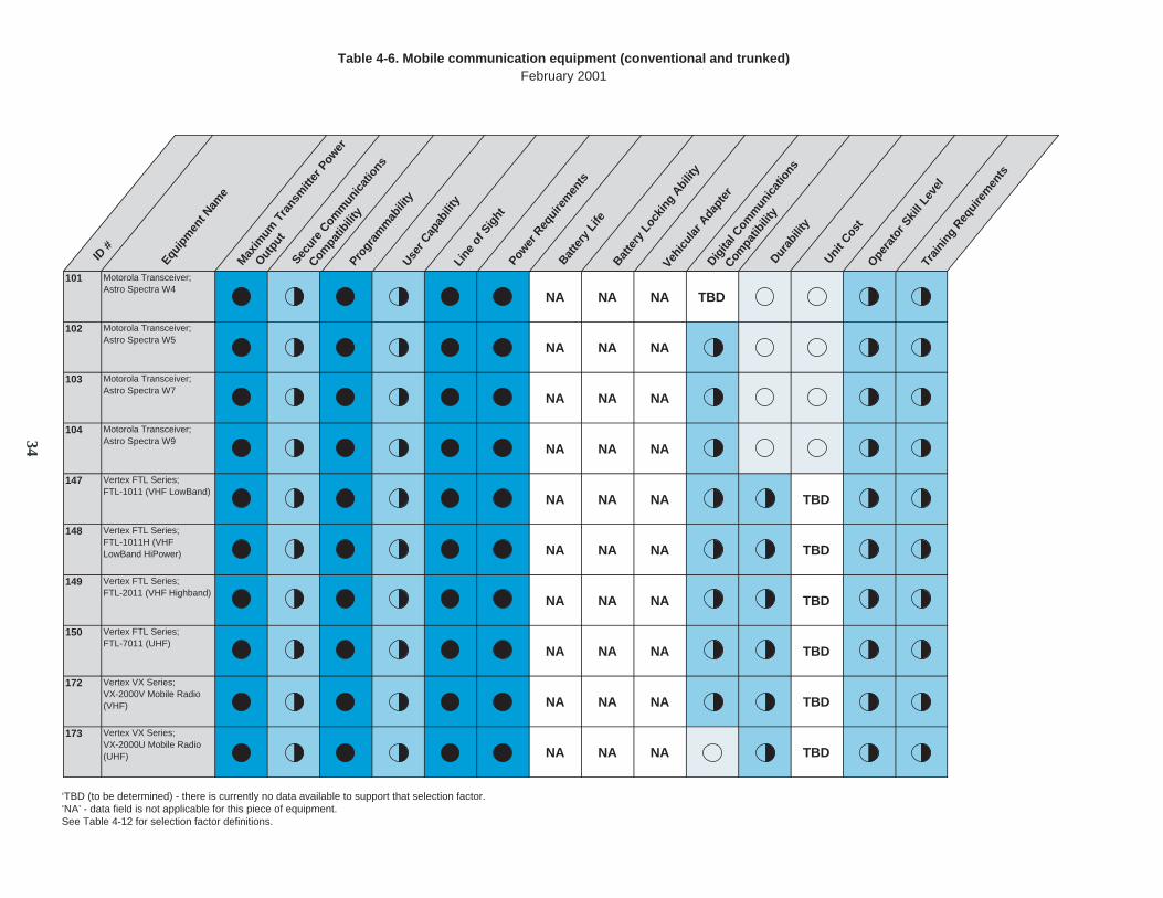
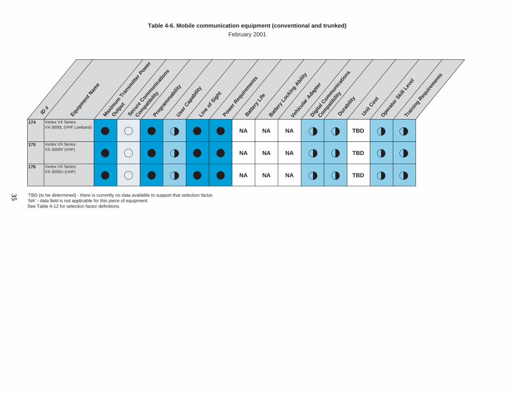
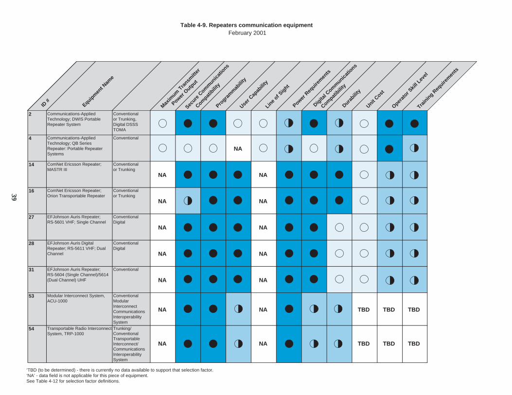
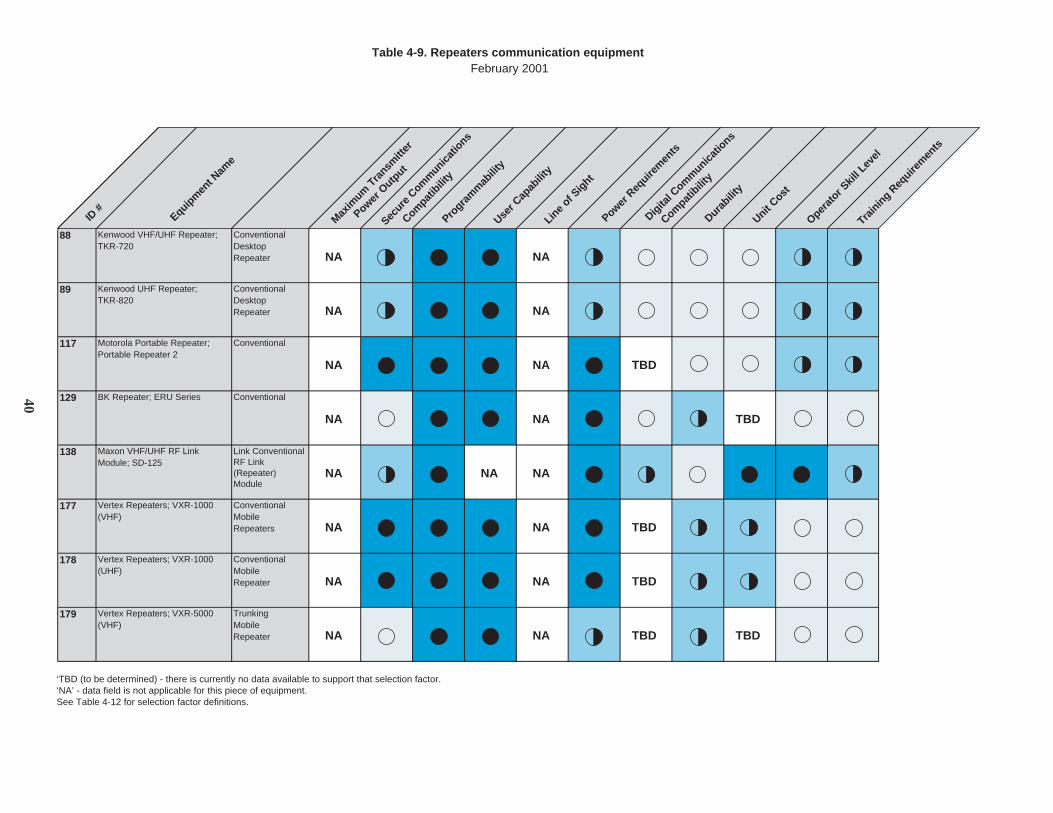
4.2 Evaluation Results
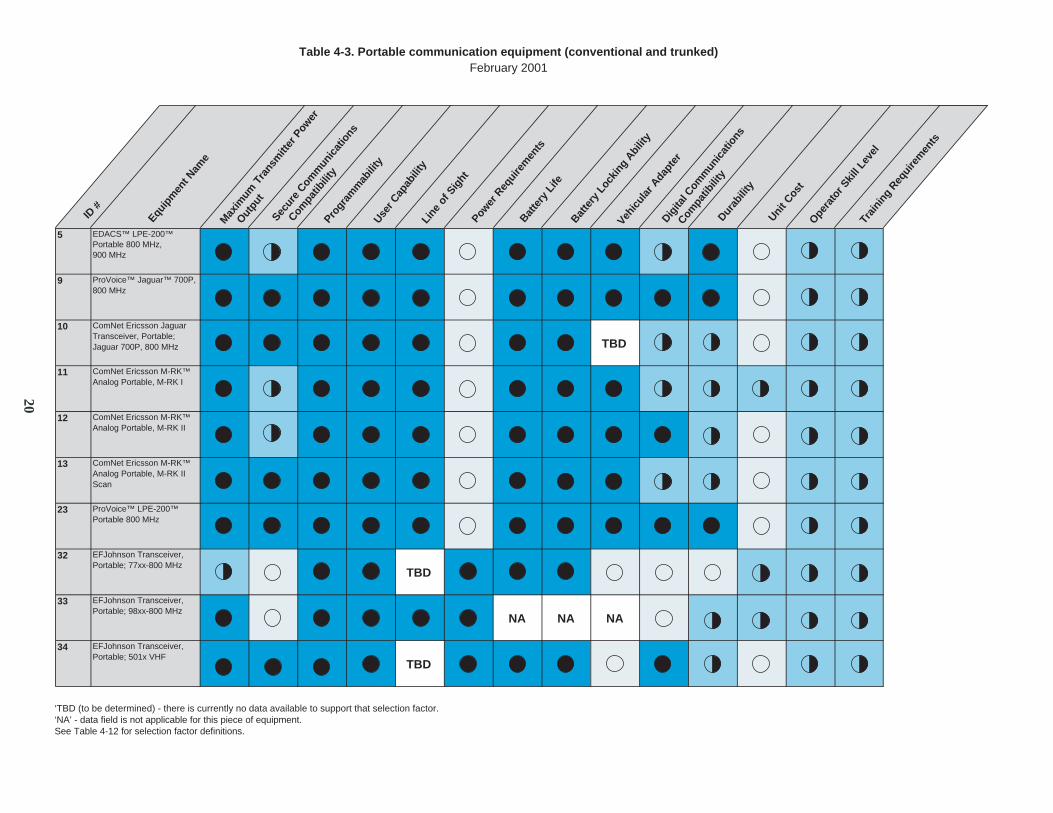
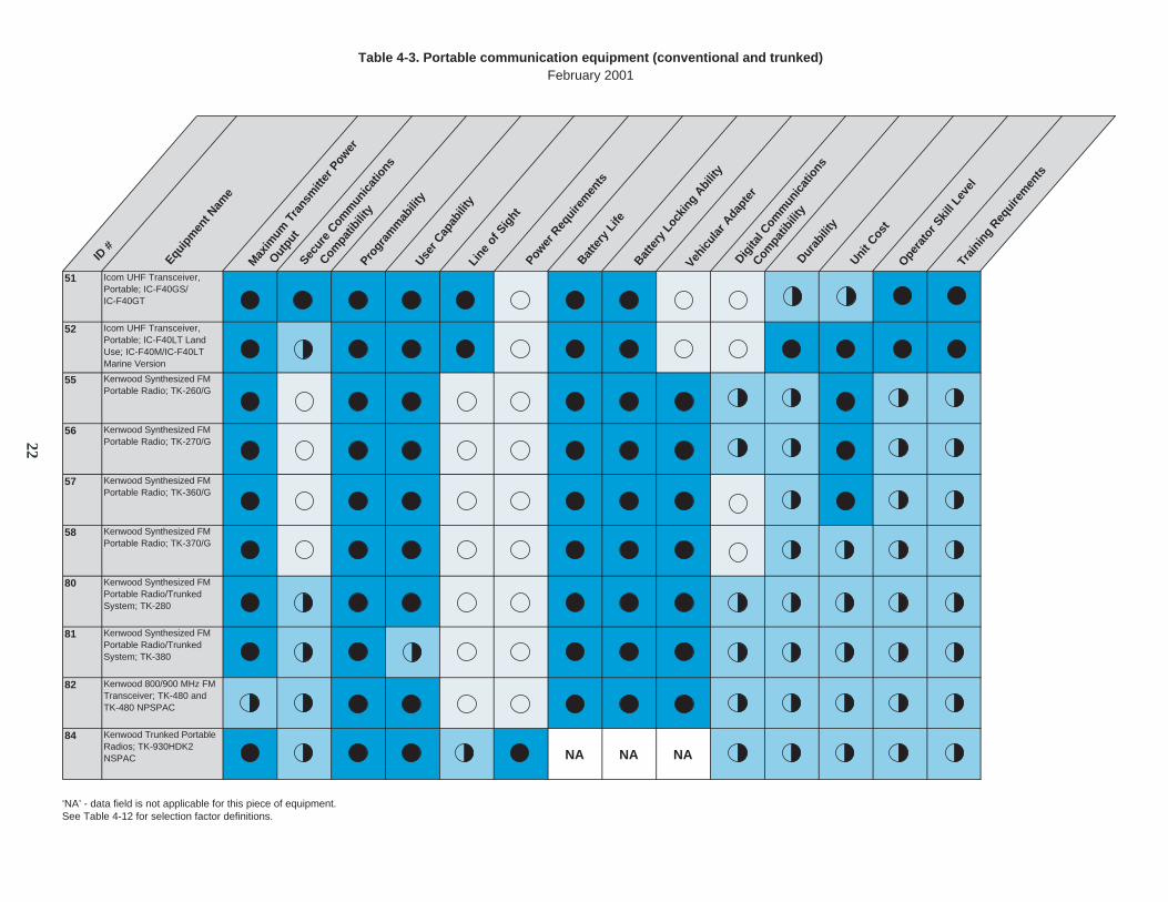
The evaluation results for the communication equipment are presented in tabular format for the181 items of communication equipment that were identified at the time this guide was written. Atable is presented for each equipment category (see sec. 4.1); the portable and mobile radios arefurther divided by their trunking capability. The rating of each item is indicated by a symbol:the open symbol indicates that the item does not meet the conditions of a specific selectionfactor, the partially filled circles indicate that the equipment partially meets the conditions of aselection factor, and the full circle indicates that the piece of equipment totally meets theconditions of a selection factor. The acronym “TBD” (to be determined) is displayed in theappropriate cell if data were not available to characterize a specific selection factor. Theacronym “NA” is displayed in the appropriate cell if the data were not applicable for a piece ofequipment. Table 4–1 provides the table number and associated table pages for each of the nineusage categories and the selection factor table.

18
Table 4–1. Evaluation results reference table
Table Name Table Number Page(s)Portable (Conventional and Trunked) 4–3 20–25Portable (Conventional) 4–4 26–30Portable (Trunked) 4–5 31Mobile (Conventional and Trunked) 4–6 32–35Mobile (Conventional) 4–7 36–37Mobile (Trunked) 4–8 38Repeater 4–9 39–40Base 4–10 41Base Station and/or Repeater 4–11 42Selection Factor Key forCommunication Equipment
4–12 43
4.2.1 Portable
The results of categorizing the communication equipment are detailed in table 4–2. Radioequipment was further divided by the communication technology (see sec. 2.1) of eachcommunication item.
There were 100 portable detectors identified in the development of this guide. These 100portable radios were further divided into three subcategories identifying their trunking capability.There were 55 portable radios using the conventional technology (see sec. 2.1.1.1) that were alsocapable of trunking (with or without an accessory). There were 44 portable radios using theconventional technology only. There was one portable radio identified as using only thetrunking technology (see sec. 2.1.1.2). Tables 4–3, 4–4, and 4–5 detail the evaluation results forall three of these subcategories, respectively.
4.2.2 Mobile
There were 54 mobile radios identified in the development of this guide. These 54 mobile radioswere further divided into three subcategories identifying their trunking capability. There were 33mobile radios using the conventional technology that were also capable of trunking (with orwithout an accessory). There were 19 mobile radios using the conventional technology only.There were two mobile radios identified as using only the trunking technology. Tables 4−6, 4–7,and 4−8 detail the evaluation results for all three of these subcategories, respectively.
4.2.3 Base Station/Repeaters
There were 27 base or repeater systems identified in the development of this guide. These 27base or repeater systems were further divided into three subcategories (repeater, base station, orbase station/repeater). There were 17 repeater systems, four base systems, and six basestation/repeater systems.
19
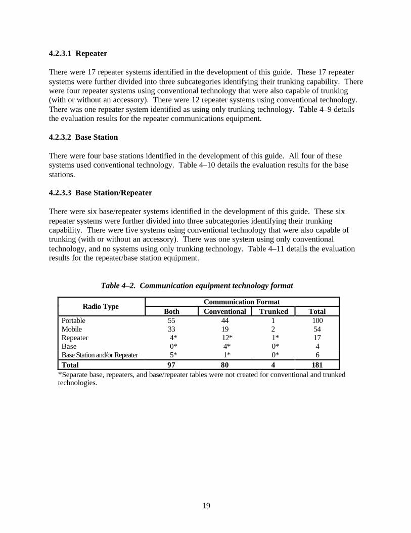
4.2.3.1 Repeater
There were 17 repeater systems identified in the development of this guide. These 17 repeatersystems were further divided into three subcategories identifying their trunking capability. Therewere four repeater systems using conventional technology that were also capable of trunking(with or without an accessory). There were 12 repeater systems using conventional technology.There was one repeater system identified as using only trunking technology. Table 4–9 detailsthe evaluation results for the repeater communications equipment.
4.2.3.2 Base Station
There were four base stations identified in the development of this guide. All four of thesesystems used conventional technology. Table 4–10 details the evaluation results for the basestations.
4.2.3.3 Base Station/Repeater
There were six base/repeater systems identified in the development of this guide. These sixrepeater systems were further divided into three subcategories identifying their trunkingcapability. There were five systems using conventional technology that were also capable oftrunking (with or without an accessory). There was one system using only conventionaltechnology, and no systems using only trunking technology. Table 4–11 details the evaluationresults for the repeater/base station equipment.
Table 4–2. Communication equipment technology format
Communication FormatRadio TypeBoth Conventional Trunked Total
Portable 55 44 1 100Mobile 33 19 2 54Repeater 4* 12* 1* 17Base 0* 4* 0* 4Base Station and/or Repeater 5* 1* 0* 6Total 97 80 4 181
*Separate base, repeaters, and base/repeater tables were not created for conventional and trunkedtechnologies.
20
Table 4-3. Portable communication equipment (conventional and trunked)February 2001
5 EDACS™ LPE-200™Portable 800 MHz, 900 MHz
9
10 ComNet Ericsson Jaguar Transceiver, Portable; Jaguar 700P, 800 MHz TBD
11 ComNet Ericsson M-RK™Analog Portable, M-RK I
12 ComNet Ericsson M-RK™ Analog Portable, M-RK II
13 ComNet Ericsson M-RK™ Analog Portable, M-RK II Scan
23
32 EFJohnson Transceiver, Portable; 77xx-800 MHz
TBD
33 EFJohnson Transceiver, Portable; 98xx-800 MHz
NA NA NA
34 EFJohnson Transceiver, Portable; 501x VHF
TBD
‘TBD (to be determined) - there is currently no data available to support that selection factor.‘NA’ - data field is not applicable for this piece of equipment.See Table 4-12 for selection factor definitions.
ID #
Equip
men
t Nam
e
Progr
amm
abili
tyUse
r Cap
abili
tyLi
ne o
f Sig
htPow
er R
equi
rem
ents
Batte
ry L
ife
Batte
ry L
ocki
ng A
bilit
y
Vehic
ular
Ada
pter
Durab
ility
Unit C
ost
Opera
tor S
kill
Leve
lTr
aini
ng R
equi
rem
ents
Max
imum
Tra
nsm
itter
Pow
er
Outpu
t Sec
ure
Comm
unic
atio
ns
Digita
l Com
mun
icat
ions
Compa
tibili
ty
Compa
tibili
ty
ProVoice™ LPE-200™ Portable 800 MHz
ProVoice™ Jaguar™ 700P, 800 MHz

ID #
Equip
men
t Nam
e
Progr
amm
abili
tyUse
r Cap
abili
tyLi
ne o
f Sig
htPow
er R
equi
rem
ents
Batte
ry L
ife
Batte
ry L
ocki
ng A
bilit
y
Vehic
ular
Ada
pter
Durab
ility
Unit C
ost
Opera
tor S
kill
Leve
lTr
aini
ng R
equi
rem
ents
35 EFJohnson Transceiver, Portable; 504x UHF
TBD
36 EFJohnson Transceiver, Portable; 508x-800 MHz
TBD
39 Icom VHF Transceiver, Portable; IC-F3
40 Icom VHF Transceiver, Portable; IC-F3S
41 Icom VHF Transceiver, Portable; IC-F3GT/IC-F3GTS
42 Icom UHF Transceiver, Portable; IC-F4
43 Icom UHF Transceiver, Portable; IC-F4S
44 Icom UHF Transceiver, Portable; IC-F4GT/IC-F4GTS
49 Icom VHF Transceiver, Portable; IC-F30GS/IC-F30GT
50 Icom VHF Transceiver, Portable; IC-F30LT Land Use; IC-F30LT Marine Version
‘TBD (to be determined) - there is currently no data available to support that selection factor.‘NA’ - data field is not applicable for this piece of equipment.See Table 4-12 for selection factor definitions.
Table 4-3. Portable communication equipment (conventional and trunked)February 2001
Max
imum
Tra
nsm
itter
Pow
er
Outpu
t Sec
ure
Comm
unic
atio
ns
Digita
l Com
mun
icat
ions
Compa
tibili
ty
Compa
tibili
ty
21
51 Icom UHF Transceiver, Portable; IC-F40GS/IC-F40GT
52 Icom UHF Transceiver, Portable; IC-F40LT Land Use; IC-F40M/IC-F40LT Marine Version
55 Kenwood Synthesized FM Portable Radio; TK-260/G
56 Kenwood Synthesized FM Portable Radio; TK-270/G
57 Kenwood Synthesized FM Portable Radio; TK-360/G
58 Kenwood Synthesized FM Portable Radio; TK-370/G
80 Kenwood Synthesized FM Portable Radio/Trunked System; TK-280
81 Kenwood Synthesized FM Portable Radio/Trunked System; TK-380
82 Kenwood 800/900 MHz FM Transceiver; TK-480 and TK-480 NPSPAC
84 Kenwood Trunked Portable Radios; TK-930HDK2 NSPAC NA NA NA
‘NA’ - data field is not applicable for this piece of equipment.See Table 4-12 for selection factor definitions.
ID #
Equip
men
t Nam
e
Progr
amm
abili
tyUse
r Cap
abili
tyLi
ne o
f Sig
htPow
er R
equi
rem
ents
Batte
ry L
ife
Batte
ry L
ocki
ng A
bilit
y
Vehic
ular
Ada
pter
Durab
ility
Unit C
ost
Opera
tor S
kill
Leve
lTr
aini
ng R
equi
rem
ents
Table 4-3. Portable communication equipment (conventional and trunked)February 2001
Max
imum
Tra
nsm
itter
Pow
er
Outpu
t Sec
ure
Comm
unic
atio
ns
Digita
l Com
mun
icat
ions
Compa
tibili
ty
Compa
tibili
ty
22

90 Motorola Astro Transceiver, Portable; Saber 1
TBD TBD TBD
91 Motorola Astro Transceiver, Portable; Saber 2
TBD TBD TBD
92 Motorola Astro Transceiver, Portable; Saber 3
TBD TBD TBD
93 Motorola Astro Transceiver, Portable; XTS 3000 Model 1
TBD TBD TBD
94 Motorola Astro Transceiver, Portable; XTS 3000 Model 2
TBD TBD TBD
95 Motorola Astro Transceiver, Portable; XTS 3000 Model 3
TBD TBD TBD
96 Motorola Astro Transceiver, Portable; XTS 3000R Series Models 1, 2, & 3 TBD TBD TBD
108 Motorola Transceiver, Portable; MT 2000 VHF
TBD TBD TBD
109 Motorola Transceiver, Portable; MTS 2000 Model I TBD TBD TBD
110 Motorola Transceiver, Portable; MTS 2000 Model II TBD TBD TBD
‘TBD (to be determined) - there is currently no data available to support that selection factor.‘NA’ - data field is not applicable for this piece of equipment.See Table 4-12 for selection factor definitions.
ID #
Equip
men
t Nam
e
Progr
amm
abili
tyUse
r Cap
abili
tyLi
ne o
f Sig
htPow
er R
equi
rem
ents
Batte
ry L
ife
Batte
ry L
ocki
ng A
bilit
y
Vehic
ular
Ada
pter
Durab
ility
Unit C
ost
Opera
tor S
kill
Leve
lTr
aini
ng R
equi
rem
ents
Table 4-3. Portable communication equipment (conventional and trunked)February 2001
Max
imum
Tra
nsm
itter
Pow
er
Outpu
t Sec
ure
Comm
unic
atio
ns
Digita
l Com
mun
icat
ions
Compa
tibili
ty
Compa
tibili
ty
23

111 Motorola Transceiver, Portable; MTS 2000 Model III TBD TBD TBD
112 Motorola Trunked Portable Radio; MTX 8000 Model B3
TBD TBD TBD TBD
113 Motorola Trunked Portable Radio; MTX 8000 Model B5
TBD TBD TBD TBD
114 Motorola Trunked Portable Radio; MTX 8000/9000 Model B7 TBD TBD TBD TBD
145 Maxon UHF Transceiver, Portable; SP-150U
162 Vertex HX Series; HX482UT UHF Portable
TBD TBD TBD
163 Vertex HX Series; HX580 Dual Protocol Hand Held
TBD TBD TBD TBD
164 Vertex VX Series; VX-210V (VHF Model)
TBD TBD TBD
165 Vertex VX Series; VX-210U (UHF Model)
TBD TBD TBD
166 Vertex VX Series; VX-400V (VHF Model)
TBD TBD TBD
‘TBD (to be determined) - there is currently no data available to support that selection factor.‘NA’ - data field is not applicable for this piece of equipment.See Table 4-12 for selection factor definitions.
ID #
Equip
men
t Nam
e
Progr
amm
abili
tyUse
r Cap
abili
tyLi
ne o
f Sig
htPow
er R
equi
rem
ents
Batte
ry L
ifeBat
tery
Loc
king
Abi
lity
Vehic
ular
Ada
pter
Durab
ility
Unit C
ost
Opera
tor S
kill
Leve
lTr
aini
ng R
equi
rem
ents
Table 4-3. Portable communication equipment (conventional and trunked)February 2001
Max
imum
Tra
nsm
itter
Pow
er
Outpu
t Sec
ure
Comm
unic
atio
ns
Digita
l Com
mun
icat
ions
Compa
tibili
ty
Compa
tibili
ty
24
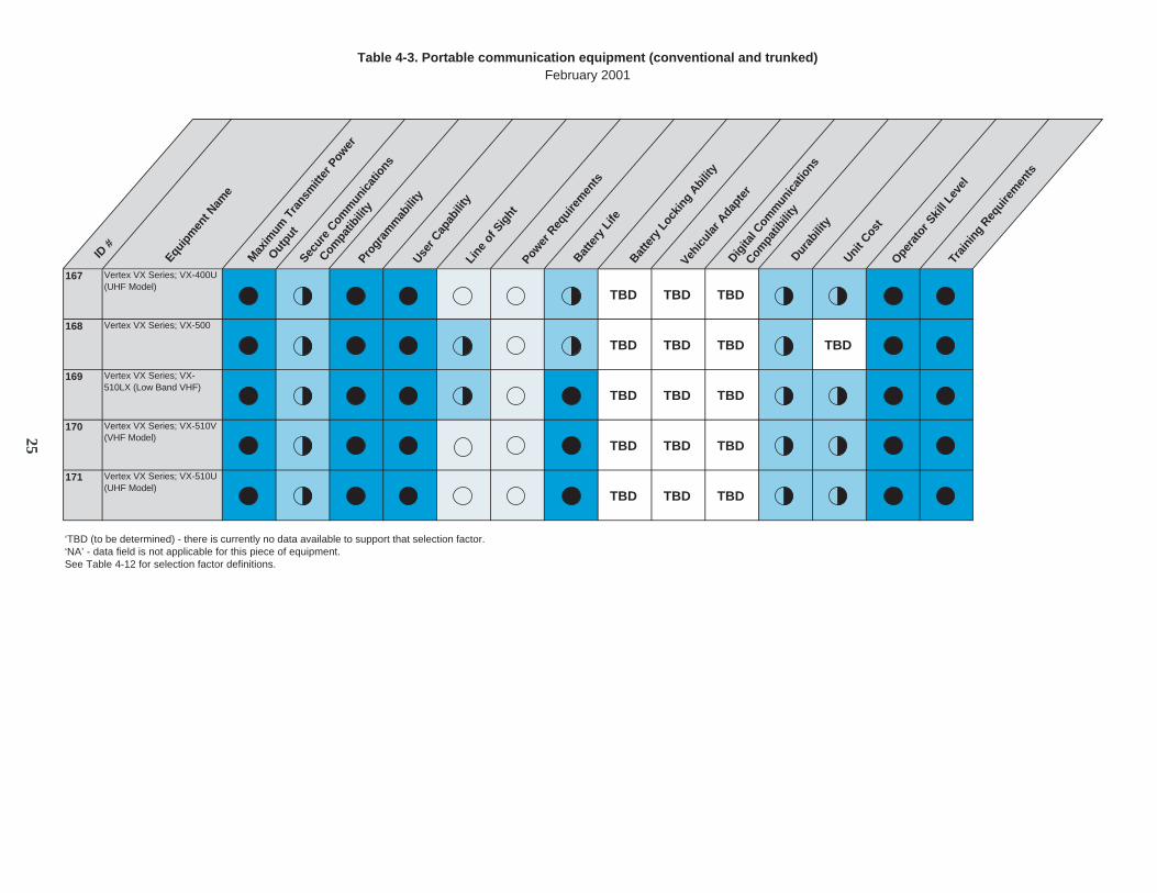
167 Vertex VX Series; VX-400U (UHF Model)
TBD TBD TBD
168 Vertex VX Series; VX-500
TBD TBD TBD TBD
169 Vertex VX Series; VX-510LX (Low Band VHF)
TBD TBD TBD
170 Vertex VX Series; VX-510V (VHF Model)
TBD TBD TBD
171 Vertex VX Series; VX-510U (UHF Model)
TBD TBD TBD
‘TBD (to be determined) - there is currently no data available to support that selection factor.‘NA’ - data field is not applicable for this piece of equipment.See Table 4-12 for selection factor definitions.
ID #
Equip
men
t Nam
e
Progr
amm
abili
tyUse
r Cap
abili
tyLi
ne o
f Sig
htPow
er R
equi
rem
ents
Batte
ry L
ife
Batte
ry L
ocki
ng A
bilit
y
Vehic
ular
Ada
pter
Durab
ility
Unit C
ost
Opera
tor S
kill
Leve
lTr
aini
ng R
equi
rem
ents
Table 4-3. Portable communication equipment (conventional and trunked)February 2001
Max
imum
Tra
nsm
itter
Pow
er
Outpu
t Sec
ure
Comm
unic
atio
ns
Digita
l Com
mun
icat
ions
Compa
tibili
ty
Compa
tibili
ty
25

1 Communications-Applied Technology; AWIS Portable Radio
3 Communications-Applied Technology; QB Series: QB-3S, QB-3S/IS/ QB-3R Portable Radios
NA
6Portable VHF, UHF, 800 MHz, M-RK I
7 EDACS™ M-RK™ Aegis™ Portable VHF, UHF, 800 MHz, M-RK II
8 EDACS™ M-RK™ Aegis™ Portable VHF, UHF, 800 MHz, M-RK II SCAN
19 ComNet Ericsson Panther Transceiver, Portable; Panther 400P
20 ComNet Ericsson Panther Transceiver, Portable; Panther 500P
21 ComNet Ericsson Panther Transceiver, Portable; Panther 600P TBD
22 ComNet Ericsson Panther Transceiver, Portable; Panther 625P TBD
74 Kenwood Transceiver, Portable; TK-2100
‘TBD (to be determined) - there is currently no data available to support that selection factor.‘NA’ - data field is not applicable for this piece of equipment.See Table 4-12 for selection factor definitions.
ID #
Equip
men
t Nam
e
Progr
amm
abili
tyUse
r Cap
abili
tyLi
ne o
f Sig
htPow
er R
equi
rem
ents
Batte
ry L
ifeBat
tery
Loc
king
Abi
lity
Vehic
ular
Ada
pter
Durab
ility
Unit C
ost
Opera
tor S
kill
Leve
lTr
aini
ng R
equi
rem
ents
Table 4-4. Portable communication equipment (conventional)February 2001
Max
imum
Tra
nsm
itter
Pow
er
Outpu
t Sec
ure
Comm
unic
atio
ns
Digita
l Com
mun
icat
ions
Compa
tibili
ty
Compa
tibili
ty
EDACS™ M-RK™ Aegis™
26

75 Kenwood Transceiver, Portable; TK-3100
76 Kenwood Transceiver, Portable; TK-3101
77 Kenwood VHF FM Transceivers; TK-290
78 Kenwood UHF FM Transceivers; TK-390
105 Motorola Transceiver, Portable; VISAR
TBD TBD TBD
106 Motorola Transceiver, Portable; HT 1000
TBD TBD TBD TBD
107 Motorola Transceiver, Portable; JT 1000
TBD TBD TBD TBD
118 Racal Transceiver, Portable; MBITR (Multiband Inter/Intra Team Radio)
119 Racal Transceiver, Portable; MSHR (Miniature Secure Handheld Radio)
120 Racal Transceiver, Portable; 20 Meter MSHR
‘TBD (to be determined) - there is currently no data available to support that selection factor.‘NA’ - data field is not applicable for this piece of equipment.See Table 4-12 for selection factor definitions.
ID #
Equip
men
t Nam
e
Progr
amm
abili
tyUse
r Cap
abili
tyLi
ne o
f Sig
htPow
er R
equi
rem
ents
Batte
ry L
ifeBat
tery
Loc
king
Abi
lity
Vehic
ular
Ada
pter
Durab
ility
Unit C
ost
Opera
tor S
kill
Leve
l
Trai
ning
Req
uire
men
ts
Table 4-4. Portable communication equipment (conventional)February 2001
Max
imum
Tra
nsm
itter
Pow
er
Outpu
t Sec
ure
Comm
unic
atio
ns
Digita
l Com
mun
icat
ions
Compa
tibili
ty
Compa
tibili
ty
27

121 Racal Transceiver, Portable; Racal 25
TBD
125 BK Synthesized FM E Series DES EPH 599, EPU 499 and EPV 499 Models TBD TBD TBD TBD
126 BK Synthesized FM Portable Radio; E Series, EPH 51 and 52 Models TBD TBD TBD TBD
127 BK Synthesized FM Portable Radio; E Series, EPI 510 Models TBD TBD TBD TBD
128 BK Synthesized FM Portable Radio; E Series, EPU & EPV 414 and 499 Models TBD TBD TBD TBD
130 BK Radio FM Transceiver, Portable; G Series, GPH Models TBD TBD TBD TBD
133 Relm Portable Radios; MPU08 (UHF)
TBD TBD TBD TBD
134 Relm Portable Radios; MPU32 (UHF)
TBD TBD TBD TBD
135 Relm Portable Radios; MPV32 (VHF)
TBD TBD TBD TBD
141 Maxon VHF/UHF Transceiver, Portable; SP-120
‘TBD (to be determined) - there is currently no data available to support that selection factor.‘NA’ - data field is not applicable for this piece of equipment.See Table 4-12 for selection factor definitions.
ID #
Equip
men
t Nam
e
Progr
amm
abili
tyUse
r Cap
abili
tyLi
ne o
f Sig
htPow
er R
equi
rem
ents
Batte
ry L
ifeBat
tery
Loc
king
Abi
lity
Vehic
ular
Ada
pter
Durab
ility
Unit C
ost
Opera
tor S
kill
Leve
lTr
aini
ng R
equi
rem
ents
Table 4-4. Portable communication equipment (conventional)February 2001
Max
imum
Tra
nsm
itter
Pow
er
Outpu
t Sec
ure
Comm
unic
atio
ns
Digita
l Com
mun
icat
ions
Compa
tibili
ty
Compa
tibili
ty
28
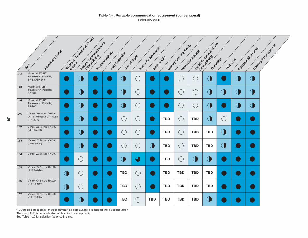
142 Maxon VHF/UHF Transceiver, Portable; SP-130/SP-140
143 Maxon VHF/UHF Transceiver, Portable; SP-200
144 Maxon VHF/UHF Transceiver, Portable; SP-300
146 Vertex Dual Band (VHF & UHF) Transceiver, Portable; FTH-2070 TBD TBD
152 Vertex VX Series; VX-10V (VHF Model)
TBD TBD TBD
153 Vertex VX Series; VX-10U (UHF Model)
TBD TBD TBD
154 Vertex VX Series; VX-300
TBD
155 Vertex HX Series; HX120 UHF Portable
TBD TBD TBD TBD TBD
156 Vertex HX Series; HX120 VHF Portable
TBD TBD TBD TBD TBD
157 Vertex HX Series; HX140 VHF Portable
TBD TBD TBD TBD TBD
‘TBD (to be determined) - there is currently no data available to support that selection factor.‘NA’ - data field is not applicable for this piece of equipment.See Table 4-12 for selection factor definitions.
ID #
Equip
men
t Nam
e M
axim
um T
rans
mitt
er P
ower
Outpu
t Sec
ure
Comm
unic
atio
ns
Progr
amm
abili
tyUse
r Cap
abili
tyLi
ne o
f Sig
htPow
er R
equi
rem
ents
Batte
ry L
ifeBat
tery
Loc
king
Abi
lity
Vehic
ular
Ada
pter
Digita
l Com
mun
icat
ions
Durab
ility
Unit C
ost
Opera
tor S
kill
Leve
lTr
aini
ng R
equi
rem
ents
Table 4-4. Portable communication equipment (conventional)February 2001
Compa
tibili
ty
Compa
tibili
ty
29

158 Vertex HX Series; HX381 VHF Portable
TBD TBD TBD TBD TBD
159 Vertex HX Series; HX381 UHF Portable
TBD TBD TBD TBD TBD
160 Vertex HX Series; HX240 VHF Portable
TBD TBD TBD
161 Vertex HX Series; HX240 UHF Portable
TBD TBD TBD
‘TBD (to be determined) - there is currently no data available to support that selection factor.‘NA’ - data field is not applicable for this piece of equipment.See Table 4-12 for selection factor definitions.
ID #
Equip
men
t Nam
e
Progr
amm
abili
tyUse
r Cap
abili
tyLi
ne o
f Sig
htPow
er R
equi
rem
ents
Batte
ry L
ifeBat
tery
Loc
king
Abi
lity
Vehic
ular
Ada
pter
Durab
ility
Unit C
ost
Opera
tor S
kill
Leve
lTr
aini
ng R
equi
rem
ents
Table 4-4. Portable communication equipment (conventional)February 2001
Max
imum
Tra
nsm
itter
Pow
er
Outpu
t Sec
ure
Comm
unic
atio
ns
Digita
l Com
mun
icat
ions
Compa
tibili
ty
Compa
tibili
ty
30

83 Kenwood 800/900 MHz FM Transceiver; TK-481
‘TBD (to be determined) - there is currently no data available to support that selection factor.‘NA’ - data field is not applicable for this piece of equipment.See Table 4-12 for selection factor definitions.
Table 4-5. Portable communication equipment (trunked)February 2001
ID #
Equip
men
t Nam
e
Progr
amm
abili
tyUse
r Cap
abili
tyLi
ne o
f Sig
htPow
er R
equi
rem
ents
Batte
ry L
ife
Batte
ry L
ocki
ng A
bilit
y
Vehic
ular
Ada
pter
Durab
ility
Unit C
ost
Opera
tor S
kill
Leve
lTr
aini
ng R
equi
rem
ents
Max
imum
Tra
nsm
itter
Pow
er
Outpu
t Sec
ure
Comm
unic
atio
ns
Digita
l Com
mun
icat
ions
Compa
tibili
ty
Compa
tibili
ty
31
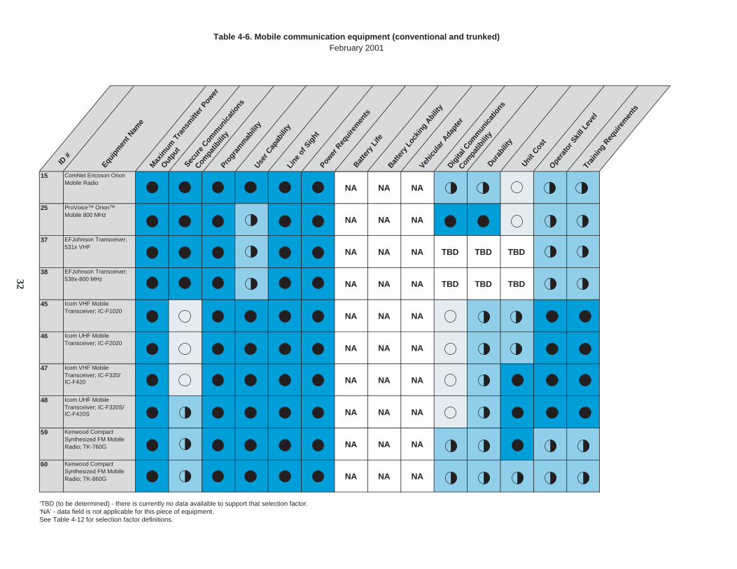
15 ComNet Ericsson Orion Mobile Radio
NA NA NA
25 ProVoice™ Orion™ Mobile 800 MHz
NA NA NA
37 EFJohnson Transceiver; 531x VHF
NA NA NA TBD TBD TBD
38 EFJohnson Transceiver; 538x-800 MHz
NA NA NA TBD TBD TBD
45 Icom VHF Mobile Transceiver; IC-F1020
NA NA NA
46 Icom UHF Mobile Transceiver; IC-F2020
NA NA NA
47 Icom VHF Mobile Transceiver; IC-F320/IC-F420 NA NA NA
48 Icom UHF Mobile Transceiver; IC-F320S/IC-F420S NA NA NA
59 Kenwood Compact Synthesized FM Mobile Radio; TK-760G NA NA NA
60 Kenwood Compact Synthesized FM Mobile Radio; TK-860G NA NA NA
‘TBD (to be determined) - there is currently no data available to support that selection factor.‘NA’ - data field is not applicable for this piece of equipment.See Table 4-12 for selection factor definitions.
Table 4-6. Mobile communication equipment (conventional and trunked)February 2001
ID #
Equip
men
t Nam
e
Progr
amm
abili
tyUse
r Cap
abili
tyLi
ne o
f Sig
htPow
er R
equi
rem
ents
Batte
ry L
ifeBat
tery
Loc
king
Abi
lity
Vehic
ular
Ada
pter
Durab
ility
Unit C
ost
Opera
tor S
kill
Leve
lTr
aini
ng R
equi
rem
ents
Max
imum
Tra
nsm
itter
Pow
er
Outpu
t Sec
ure
Comm
unic
atio
ns
Digita
l Com
mun
icat
ions
Compa
tibili
ty
Compa
tibili
ty
32
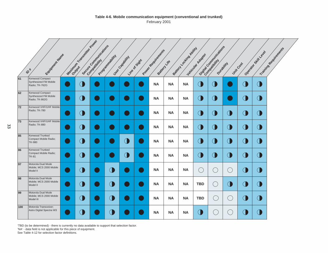
61 Kenwood Compact Synthesized FM Mobile Radio; TK-762G NA NA NA
62 Kenwood Compact Synthesized FM Mobile Radio; TK-862G NA NA NA
72 Kenwood VHF/UHF Mobile Radio; TK-780
NA NA NA
73 Kenwood VHF/UHF Mobile Radio; TK-880
NA NA NA
85 Kenwood Trunked Compact Mobile Radio; TK-980 NA NA NA
86 Kenwood Trunked Compact Mobile Radio;TK-81 NA NA NA
97 Motorola Dual Mode Mobile; MCS 2000 Mobile Model II NA NA NA
98 Motorola Dual Mode Mobile; MCS 2000 Mobile Model II NA NA NA TBD
99 Motorola Dual Mode Mobile; MCS 2000 Mobile Model III NA NA NA TBD
100 Motorola Transceiver; Astro Digital Spectra W3
NA NA NA
‘TBD (to be determined) - there is currently no data available to support that selection factor.‘NA’ - data field is not applicable for this piece of equipment.See Table 4-12 for selection factor definitions.
Table 4-6. Mobile communication equipment (conventional and trunked)February 2001
ID #
Equip
men
t Nam
e
Progr
amm
abili
tyUse
r Cap
abili
tyLi
ne o
f Sig
htPow
er R
equi
rem
ents
Batte
ry L
ifeBat
tery
Loc
king
Abi
lity
Vehic
ular
Ada
pter
Durab
ility
Unit C
ost
Opera
tor S
kill
Leve
lTr
aini
ng R
equi
rem
ents
Max
imum
Tra
nsm
itter
Pow
er
Outpu
t Sec
ure
Comm
unic
atio
ns
Digita
l Com
mun
icat
ions
Compa
tibili
ty
Compa
tibili
ty
33
101 Motorola Transceiver; Astro Spectra W4
NA NA NA TBD
102 Motorola Transceiver; Astro Spectra W5
NA NA NA
103 Motorola Transceiver; Astro Spectra W7
NA NA NA
104 Motorola Transceiver; Astro Spectra W9
NA NA NA
147 Vertex FTL Series; FTL-1011 (VHF LowBand)
NA NA NA TBD
148 Vertex FTL Series; FTL-1011H (VHF LowBand HiPower) NA NA NA TBD
149 Vertex FTL Series; FTL-2011 (VHF Highband)
NA NA NA TBD
150 Vertex FTL Series; FTL-7011 (UHF)
NA NA NA TBD
172 Vertex VX Series; VX-2000V Mobile Radio (VHF) NA NA NA TBD
173 Vertex VX Series; VX-2000U Mobile Radio (UHF) NA NA NA TBD
‘TBD (to be determined) - there is currently no data available to support that selection factor.‘NA’ - data field is not applicable for this piece of equipment.See Table 4-12 for selection factor definitions.
Table 4-6. Mobile communication equipment (conventional and trunked)February 2001
ID #
Equip
men
t Nam
e
Progr
amm
abili
tyUse
r Cap
abili
tyLi
ne o
f Sig
htPow
er R
equi
rem
ents
Batte
ry L
ifeBat
tery
Loc
king
Abi
lity
Vehic
ular
Ada
pter
Durab
ility
Unit C
ost
Opera
tor S
kill
Leve
lTr
aini
ng R
equi
rem
ents
Max
imum
Tra
nsm
itter
Pow
er
Outpu
t Sec
ure
Comm
unic
atio
ns
Digita
l Com
mun
icat
ions
Compa
tibili
ty
Compa
tibili
ty
34
174 Vertex VX Series; VX-3000L (VHF Lowband)
NA NA NA TBD
175 Vertex VX Series; VX-3000V (VHF)
NA NA NA TBD
176 Vertex VX Series; VX-3000U (UHF)
NA NA NA TBD
‘TBD (to be determined) - there is currently no data available to support that selection factor.‘NA’ - data field is not applicable for this piece of equipment.See Table 4-12 for selection factor definitions.
Table 4-6. Mobile communication equipment (conventional and trunked)
February 2001
ID #
Equip
men
t Nam
e
Progr
amm
abili
tyUse
r Cap
abili
tyLi
ne o
f Sig
htPow
er R
equi
rem
ents
Batte
ry L
ifeBat
tery
Loc
king
Abi
lity
Vehic
ular
Ada
pter
Durab
ility
Unit C
ost
Opera
tor S
kill
Leve
lTr
aini
ng R
equi
rem
ents
Max
imum
Tra
nsm
itter
Pow
er
Outpu
t Sec
ure
Comm
unic
atio
ns
Digita
l Com
mun
icat
ions
Compa
tibili
ty
Compa
tibili
ty
35

17 ComNet Ericsson Panther Transceiver, Mobile Panther 400M NA NA NA
18 ComNet Ericsson Panther Transceiver, Mobile Panther 600M NA NA NA
63 Kenwood Compact Synthesized FM Mobile Radio; TK-760H NA NA NA
64 Kenwood Compact Synthesized FM Mobile Radio; TK-860H NA NA NA
65 Kenwood Compact Synthesized FM Mobile Radio; TK-762H NA NA NA
66 Kenwood Compact Synthesized FM Mobile Radio; TK-862H NA NA NA
67 Kenwood Public Safety Mobile FM Radios;TK-690H NA NA NA
68 Kenwood Public Safety Mobile FM Radios; TK-790
NA NA NA
69 Kenwood Public Safety Mobile FM Radios; TK-790H NA NA NA
70 Kenwood Public Safety Mobile FM Radios; TK-890
NA NA NA
‘TBD (to be determined) - there is currently no data available to support that selection factor.‘NA’ - data field is not applicable for this piece of equipment.See Table 4-12 for selection factor definitions.
Table 4-7. Mobile communication equipment (conventional)February 2001
ID #
Equip
men
t Nam
e
Progr
amm
abili
tyUse
r Cap
abili
tyLi
ne o
f Sig
htPow
er R
equi
rem
ents
Batte
ry L
ifeBat
tery
Loc
king
Abi
lity
Vehic
ular
Ada
pter
Durab
ility
Unit C
ost
Opera
tor S
kill
Leve
lTr
aini
ng R
equi
rem
ents
Max
imum
Tra
nsm
itter
Pow
er
Outpu
t Sec
ure
Comm
unic
atio
ns
Digita
l Com
mun
icat
ions
Compa
tibili
ty
Compa
tibili
ty
36

71 Kenwood Public Safety Mobile FM Radios;TK-890H NA NA NA
123 BK Radio FM Transceiver; EMH 599 2X
NA NA NA TBD
124 BK Synthesized FM Mobile Radio; EMV
TBD NA NA NA TBD
131 BK Radio Airborne Transceiver; KFM 985
NA NA NA TBD TBD
132 Relm Mobile Radio; 256NB
NA NA NA TBD TBD TBD
136 Relm Mobile Radios; SMV2516
NA NA NA TBD
137 Relm Mobile Radios; SMV4016
NA NA NA TBD
139 Maxon Scanning Transceiver; SM-2000 Series NA NA NA
140 Maxon Scanning Transceiver; SM-4000 Series NA NA NA
‘TBD (to be determined) - there is currently no data available to support that selection factor.‘NA’ - data field is not applicable for this piece of equipment.See Table 4-12 for selection factor definitions.
Table 4-7. Mobile communication equipment (conventional)February 2001
ID #
Equip
men
t Nam
e
Progr
amm
abili
tyUse
r Cap
abili
tyLi
ne o
f Sig
htPow
er R
equi
rem
ents
Max
imum
Tra
nsm
itter
Pow
er
Outpu
t Sec
ure
Comm
unic
atio
ns
Digita
l Com
mun
icat
ions
Compa
tibili
ty
Compa
tibili
ty
Batte
ry L
ifeBat
tery
Loc
king
Abi
lity
Vehic
ular
Ada
pter
Durab
ility
Unit C
ost
Opera
tor S
kill
Leve
lTr
aini
ng R
equi
rem
ents
37

79 Kenwood Trunked Mobile Radio; TK-980 NSPAC
NA NA NA
151 Vertex GX4800UT Mobile Transceiver
NA NA NA TBD TBD
Table 4-8. Mobile communication equipment (trunked)February 2001
ID #
Equip
men
t Nam
e
Progr
amm
abili
tyUse
r Cap
abili
tyLi
ne o
f Sig
htPow
er R
equi
rem
ents
Batte
ry L
ifeBat
tery
Loc
king
Abi
lity
Vehic
ular
Ada
pter
Durab
ility
Unit C
ost
Opera
tor S
kill
Leve
lTr
aini
ng R
equi
rem
ents
‘TBD (to be determined) - there is currently no data available to support that selection factor.‘NA’ - data field is not applicable for this piece of equipment.See Table 4-12 for selection factor definitions.
Max
imum
Tra
nsm
itter
Pow
er
Outpu
t Sec
ure
Comm
unic
atio
ns
Digita
l Com
mun
icat
ions
Compa
tibili
ty
Compa
tibili
ty
38
2 Communications-AppliedTechnology; DWIS PortableRepeater System
Conventionalor Trunking,Digital DSSSTOMA
4 Communications-AppliedTechnology; QB SeriesRepeater: Portable RepeaterSystems
Conventional
NA
14 ComNet Ericsson Repeater;MASTR III
Conventionalor Trunking
NA NA
16 ComNet Ericsson Repeater;Orion Transportable Repeater
Conventionalor Trunking
NA NA
27 EFJohnson Auris Repeater;RS-5601 VHF; Single Channel
ConventionalDigital
NA NA
28 EFJohnson Auris DigitalRepeater; RS-5611 VHF; DualChannel
ConventionalDigital
NA NA
31 EFJohnson Auris Repeater;RS-5604 (Single Channel)/5614(Dual Channel) UHF
Conventional
NA NA
53 Modular Interconnect System,ACU-1000
ConventionalModular Interconnect CommunicationsInteroperabilitySystem
NA NA TBD TBD TBD
54 Transportable Radio InterconnectSystem, TRP-1000
Trunking/ Conventional Transportable Interconnect/ CommunicationsInteroperabilitySystem
NA NA TBD TBD TBD
‘TBD (to be determined) - there is currently no data available to support that selection factor.‘NA’ - data field is not applicable for this piece of equipment.See Table 4-12 for selection factor definitions.
Table 4-9. Repeaters communication equipment February 2001
ID #
Equipm
ent N
ame
Progra
mm
abilit
y
User C
apab
ility
Line
of Sig
ht
Power R
equire
men
ts
Durabilit
y
Unit Cost
Operat
or Skil
l Lev
el
Train
ing R
equire
men
ts
Maxim
um T
ransm
itter
Power O
utput
Secure
Com
munica
tions
Digita
l Com
munica
tions
Compat
ibilit
y
Compat
ibilit
y
39
88 Kenwood VHF/UHF Repeater; TKR-720
Conventional Desktop Repeater NA NA
89 Kenwood UHF Repeater; TKR-820
Conventional Desktop Repeater NA NA
117 Motorola Portable Repeater; Portable Repeater 2
Conventional
NA NA TBD
129 BK Repeater; ERU Series Conventional
NA NA TBD
138 Maxon VHF/UHF RF Link Module; SD-125
Link Conventional RF Link (Repeater) Module
NA NA NA
177 Vertex Repeaters; VXR-1000 (VHF)
Conventional Mobile Repeaters NA NA TBD
178 Vertex Repeaters; VXR-1000 (UHF)
Conventional Mobile Repeater NA NA TBD
179 Vertex Repeaters; VXR-5000 (VHF)
Trunking Mobile Repeater NA NA TBD TBD
‘TBD (to be determined) - there is currently no data available to support that selection factor.‘NA’ - data field is not applicable for this piece of equipment.See Table 4-12 for selection factor definitions.
Table 4-9. Repeaters communication equipment February 2001
ID #
Equipm
ent N
ame
Progra
mm
abilit
y
User C
apab
ility
Line
of Sig
ht
Power R
equire
men
ts
Durabilit
y
Unit Cost
Operat
or Skil
l Lev
el
Train
ing R
equire
men
ts
Maxim
um T
ransm
itter
Power O
utput
Secure
Com
munica
tions
Digita
l Com
munica
tions
Compat
ibilit
y
Compat
ibilit
y
40

26 EFJohnson Auris Digital Base Station; RS-5601 VHF; Single Channel
Conventional Digital Base Station NA NA
29 EFJohnson Auris Digital Base Station; RS-5611 VHF; Dual Channel
Conventional Digital Base Station NA NA
87 Kenwood VHF Base Tranceiver; TKB-720
Conventional Base Radio
NA
122 BK Base Station; EBU Series Conventional Base Station
NA NA TBD TBD
‘TBD (to be determined) - there is currently no data available to support that selection factor.‘NA’ - data field is not applicable for this piece of equipment.See Table 4-12 for selection factor definitions.
Table 4-10. Base station communication equipment February 2001
ID #
Equipm
ent N
ame
Progra
mm
abilit
y
User C
apab
ility
Line
of Sig
ht
Power R
equire
men
ts
Durabilit
y
Unit Cost
Operat
or Skil
l Lev
el
Train
ing R
equire
men
ts
Maxim
um T
ransm
itter
Power O
utput
Secure
Com
munica
tions
Digita
l Com
munica
tions
Compat
ibilit
y
Compat
ibilit
y
41

24 ProVoice™ MASTR™ III Base Station 800 MHz
Mobile Base Station or Repeater (Trunking is the primary operating mode) NA NA
30 EFJohnson Auris Digital Repeater/Basestation; RS-5604 (Single Channel)/5614 (Dual Channel) UHF
Digital Base Station (Conventional)
NA NA
115 Motorola Station/Repeater; QUANTAR
Functions as a Base Station or Repeater (Conventional or Trunking) NA NA
116 Motorola Station/Repeater; QUANTRO
Base Station/Repeater (Conventional/Trunking)
NA NA
180 Vertex Repeaters or Base Station; VXR-5000 (UHF)
Mobile Base Station orRepeater (Conventional; Trunking Capable with Optional Accessory Board)
NA NA TBD NA TBD
181 Vertex Repeater or Base Station; VXR-7000 (VHF)
Mobile Base Station orRepeater (Conventional; Optional VX-Trunk Operation) NA NA TBD NA TBD
‘TBD (to be determined) - there is currently no data available to support that selection factor.‘NA’ - data field is not applicable for this piece of equipment.See Table 4-12 for selection factor definitions.
Table 4-11. Base station and/or repeater communication equipment February 2001
ID #
Equipm
ent N
ame
Progra
mm
abilit
y
User C
apab
ility
Line
of Sig
ht
Power R
equire
men
ts
Durabilit
y
Unit Cost
Operat
or Skil
l Lev
el
Train
ing R
equire
men
ts
Maxim
um T
ransm
itter
Power O
utput
Secure
Com
munica
tions
Digita
l Com
munica
tions
Compat
ibilit
y
Compat
ibilit
y
42

Maxim
um T
ransm
itter
Secure
Com
munica
tions
Progra
mm
abilit
y
User C
apab
ility
Line
of Sig
ht
Power R
equire
men
ts
Power R
equire
men
ts
Batte
ry L
ife (P
ortable)
Batte
ry L
ockin
g Abilit
y
Vehicu
lar A
dapte
r
Digita
l Com
munica
tions
Power O
utput
Compat
ibilit
y
(Porta
ble)
(Mobile
and R
epea
ter)
(Mobile
and R
epea
ter)
(Porta
ble)
(Porta
ble)
(Porta
ble)
Compat
ibilit
y
Durabilit
y
Unit Cost
Operat
or Skil
l Lev
el
Train
ing R
equire
men
ts
Train
ing R
equire
men
ts
Power output of 3 W to 6 W
Capable of secure transmissions without an accessory
Can be programmed/ reprogrammed by authorized personnel
Unlimited capability
Transmission can travel 10 miles or more
Operates off battery pack, external dc, or ac adapter
Uses 12 V dc to 15 V dc
Equal to or greater than 8 h
Battery securely locked into place on the radio and cannot be dislodged by bumping or dropping
Has vehicle adapter (with built-in amplifier) that connects to vehicle’s electrical system and external antenna
Capable of digital transmissions without an adaptor
Designed for rugged use and is submersible in water
Less than or equal to $500 per unit
No special skills or training required
No special training required
No special training required
Operates off battery pack or external dc adapter
Power output of more than 1.5 W but less than 3 W
Capable of secure transmissions with an accessory
Can be programmed/ reprogrammed by vendor only
Fixed capability
Transmission can travel 5 miles to 10 miles
Operates off battery pack or ac adapter
Uses 120/220 V ac
Greater than4 h but lessthan 8 h
Capable of digital transmissions with an adaptor
Designed for rugged use but is not submersiblein water
Greater than $500 but less than $1000 per unit
No special skills butsome training required
Less than 60 min training required
Less than 8 h training required
Power output of less than 1.5 W
Not capable of secure transmissions
Can be programmed/ reprogrammed by the end user
Restrictive capability
Transmission can travel less than 5 miles
Operates off battery pack only
Uses voltage other than standard 12 V dc to 15 V dc or 110/220 V ac
Less than 4 hBattery not locked into place
Does not have optional vehicle adapter
Not capable of digital transmissions
Designed for standard use only
Greater than $1000 per unit
Technical background required to operate equipment
More than 60 min training required
More than 8 h training required
The gray cells designate that the symbol is not applicable for the selection factor.
Table 4-12. Selection factor key for communication equipment February 2001
43

APPENDIX A––RECOMMENDED QUESTIONS ONCOMMUNICATION EQUIPMENT

A–1
APPENDIX A––RECOMMENDED QUESTIONS ONCOMMUNICATION EQUIPMENT5
Buying detection, protection, decontamination, and communication equipment to respond to thethreatened terrorist use of chemical or biological warfare agents may be new for public safetyagencies. To help procurement officials obtain the best value for their domestic preparednessdollar, a series of questions was excerpted from a report titled: “Domestic Preparedness Programin Defense of Weapons of Mass Destruction Report on Communication Equipment” (see detailedreference in appendix B). These questions should assist officials in selecting products from thelarge number in the present day marketplace. Requesting vendors to provide written responsesto specific questions may also be helpful in the decision process.
Note: The included question lists are meant as starting points only. The consumer should addany questions pertinent to a particular application.
Portable Radio Accessories
1. Can I use the accessory with or without a facemask?2. Can I use the accessory with an encapsulated suit?3. What radios are compatible with the unit?4. How does the equipment function in high noise (a lot of electrical or environmental
interference) surroundings?5. Does the equipment require batteries? How many? What type? Battery life?6. Is the equipment waterproof?7. Is the equipment spark proof, intrinsically safe, or explosion proof?8. Is the product voice activated? Push-to-talk (PTT)? Both? How big is the PTT switch?9. Can the PTT be activated through a suit? How tactile is the switch?10. What receiver options are available?11. Can the unit be decontaminated?12. Does other protective equipment affect the clarity of communication?13. Will communication capability be affected by the removal or addition of any personal
protective equipment (PPE)?14. Is the product ruggedly constructed? What is the warranty period?15. Who uses the product now? Where? For what application?16. How much does a complete unit with radio interface cable cost?17. What is the cost of ownership over time? (i.e., batteries, additional components, etc.)
Portable Radio Capabilities
1. Is voice communication continuous?2. What is the level of intrinsic safety?3. What materials are used in the construction of the equipment?4. Is the equipment waterproof? Immersion proof?5. What is the power source? Batteries (type)? Other?
5The information in Appendix A was provided by the National Domestic Preparedness Office (NDPO) in coordination with the National Instituteof Justice and Technical Support Working Group.

A–2
6. What is the battery life? Is there a low battery warning?7. Can it be used while wearing breathing apparatus?8. What kind of accessories are available for the equipment?9. Are system components and accessories interchangeable?10. How quickly can the equipment be deployed?11. Is the equipment shielded against RF or electromagnetic interference?12. How easy is it to use? How much training is required?13. How many people can be on the communication system at once?14. What type of warranty does it come with?15. Is the equipment built to a quality standard? What standard?

APPENDIX B––REFERENCES

B–1
APPENDIX B––REFERENCES
1. Andy Ibbetson, Domestic Preparedness Program in Defense of Weapons of MassDestruction Report on Communication Equipment, CON-SPACE Communication Inc.,October 26, 1999.

APPENDIX C––EQUIPMENT SAFETY

C–1
APPENDIX C––EQUIPMENT SAFETY6
Types of Electrical Equipment
Some examples of commonly used electrical equipment by rescuers in hazardous locations aretwo-way radios, hard-line and sound powered communication systems, gas detectors PASSdevices, pagers, and ventilation equipment. However, electrical equipment, as defined byFactory Mutual Research in their Approval Standard 3600, is “All items applied as a whole or inpart for the utilization of electrical energy. These include, among others, items for thegeneration, transmission, storage, measurement, regulation, conversion, and consumption ofelectrical energy and items for telecommunications.”
Equipment Safety
When selecting electrically powered communication equipment for use in a hazardous orpotentially hazardous environment, it is important to choose equipment that has been designed andapproved to be spark proof, explosion proof, or intrinsically safe. The classifications for hazardouslocations are in the National Electrical Code (NFPA 70).
The following is an abbreviated list of the different classifications and what they mean. If thereis any doubt about the approval rating on a particular piece of equipment, check the label. InNorth America, all intrinsically safe or explosion proof equipment has to carry a label that liststhe hazardous location or hazardous locations for which it has been tested and approved. If thehazardous location information is not on the label, it is not approved for that location and, ifthere is no label, the equipment is not approved. If the physical size of the equipment prohibits alisting of approved locations, as a minimum requirement, the equipment will have the mark ofthe Nationally Recognized Test Laboratory (NTRL) that did the testing. If there is any questionabout the approval status for a piece of electrical equipment, request a copy of the certificationrecord or approval agreement from the equipment manufacturer or distributor and keep it on filefor future reference.
6Appendix C has been copied in its entirety from “Report on Communication Equipment, (Domestic Preparedness Program in Defense ofWeapons of Mass Destruction).” This is a circulated document prepared by Andy Ibbetson, CON-SPACE Communication Inc., October 26,1999.

C–2
National Electrical Code (NEC) Classifications for Hazardous Locations
Class I Locations where there is a danger of explosion due to flammable gases or vaporspresent in quantities sufficient to produce explosive or ignitable mixtures.
Class II Locations where there is a danger of explosion due to the presence of combustible orelectrically conductive dust.
Class III Locations where there is a danger of explosion or flash fire due to the presence of easilyignitable fibers or flyings.
Classes are separated into Divisions 1 and 2
Division 1 Locations where the gases, vapors, conductive dust, combustible dust, flyings and/orfibers are present in the air in potentially flammable concentrations continuously,frequently, or intermittently under normal operating conditions.
Division 2 Locations where the gases, vapors, conductive dust, combustible dust, flyings and/orfibers might become hazardous in the event of mechanical breakdown, accident, failure,or the abnormal operation of equipment.
Classes are further divided into Groups
Class IGroup A Acetylene.Group B Butadiene, Hydrogen, Ethylene Oxide, Propylene Oxide, and Acrolien.Group C Acetaldehyde, Ethylene, and Ether Vapors.Group D Acetone, Ammonia, Benzene, Butane, Cyclopropane, Gasoline, Hexane, Methane,
Methanol, Natural Gas, Naptha, and Propane.
Class II
Group E Combustible metal dust including aluminium, magnesium and their commercial alloys.Group F Combustible carbonaceous dusts including Carbon Black, coal, and charcoal.Group G Combustible dusts not listed in groups E or F including flour, grain, wood, and plastic.
Class III No Groups.

C–3
Zones
The 1996 version of the National Electrical Code (NEC) included Article 505 – Class I, Zone 0,1, and 2 Locations. Article 505 specifies an alternative hazardous location identification schemefor Class I environments. The Zone system does not replace the aforementioned classificationsystem, but since Zones are common classifications elsewhere in the world, its inclusion in theNEC should be considered a step toward standardization of I.S. approval standards with othercountries.
Special Note: NEC Article 500–3 states that if Article 505 is used, area classification, wiring,and equipment selection must be done under the supervision of a qualified RegisteredProfessional Engineer.
Class 1 – Zones*Zone 0 Location in which ignitable concentrations of flammable gases and vapors are
present either continuously or for long periods of time.
Zone 1 Location in which ignitable concentrations of flammable gases or vapors thatare likely to exist under normal operating conditions or may exist frequentlybecause of repair maintenance, leakage, or breakdown. Or the location isadjacent to a Class I, Zone 0 from which ignitable concentrations could becommunicated, unless prevented by adequate positive pressure ventilation andsafeguards are in place to prevent ventilation failure.
Zone 2 Location in which ignitable concentrations of flammable gases or vapors thatare not likely to occur in normal operation and if they do occur will exist onlyfor a short period of time. An area where liquids gases or vapors are normallyconfined in closed containers or systems that could escape due to an accidentalrupture, breakdown, or abnormal operation of equipment. Or where theignitable concentrations are normally prevented by positive mechanicalventilation but could become hazardous due to the failure or abnormal operationof the ventilation equipment. Or the location is adjacent to a Class I, Zone 1from which ignitable concentrations could be communicated, unless preventedby adequate positive pressure ventilation and safeguards are in place to preventventilation failure.
Group Equivalents
Zone System = Current SystemClass I, Group IIc = Class I, Groups A & B
Class I, Group IIb = Class I, Group C
Class I, Group IIa = Class I, Group D
*The above is an abbreviated version of the Zone/Group system and is for information purposes only.Refer to the NEC Article 505 for complete descriptions of Class I, Zones and Groups.

C–4
Examples of Classifications and Corresponding Rescue Sites
Note: Refer to the National Electrical Code Articles 500, 501, 502, 503, 505 for a completedescription of Hazardous Area Classifications and Group descriptions including an alternativehazardous location identification scheme (Zone Classification System).
Class I, Divisions 1 & 2Petroleum refineries, dry cleaning plants, petrochemical plants, hospitals, utilities, aircraft hangers,paint manufacturers, dip tanks containing flammable or combustible liquids, and spray finishing areas.
Class II, Divisions 1 & 2Grain elevators, flour and feed mills, confectionery plants, fireworks manufacturing and storage, grainships, areas for packaging and handling of pulverized sugar and cocoa, manufacturing and storage ofmagnesium or aluminium, spice grinding mills, and some coal handling plants.
Class III, Divisions 1 & 2Wood working plants, textile mills, cotton gins, cottonseed mills, flax producing plants, knitting mills,and weaving mills.
NOTE: The above is an example only. Individual group classifications also apply to the above andwere omitted for brevity. To determine Classifications for specific locations, consult with your safetyofficer.