USB Monitor Control Class Specification - USB.org - … · Revision 1.0 USB Monitor Control Class...
22
USB Monitor Control Class Specification Revision 1.0 January 5, 1998
Transcript of USB Monitor Control Class Specification - USB.org - … · Revision 1.0 USB Monitor Control Class...

USB Monitor Control Class Specification
Revision 1.0
January 5, 1998

USB Monitor Control Class Specification Revision 1.0
ii
Scope of this RevisionThis revision is intended for implementation.
Revision History
Rev Date Filename Comments
1.0 January 5, 1998 USBMON10.DOC Initial release for implementation
USB Monitor Control Class Specification Copyright 1996, 1997 and 1998, USB Implementers Forum
All rights reserved.
Revision 1.0 USB Monitor Control Class Specification
iii
INTELLECTUAL PROPERTY DISCLAIMER
THIS SPECIFICATION IS PROVIDED “AS IS” WITH NO WARRANTIES WHATSOEVER INCLUDING ANYWARRANTY OF MERCHANTABILITY, FITNESS FOR ANY PARTICULAR PURPOSE, OR ANY WARRANTYOTHERWISE ARISING OUT OF ANY PROPOSAL, SPECIFICATION, OR SAMPLE.
A LICENSE IS HEREBY GRANTED TO REPRODUCE AND DISTRIBUTE THIS SPECIFICATION FORINTERNAL USE ONLY. NO OTHER LICENSE, EXPRESS OR IMPLIED, BY ESTOPPEL OR OTHERWISE, TOANY OTHER INTELLECTUAL PROPERTY RIGHTS IS GRANTED OR INTENDED HEREBY.
AUTHORS OF THIS SPECIFICATION DISCLAIM ALL LIABILITY, INCLUDING LIABILITY FORINFRINGEMENT OF PROPRIETARY RIGHTS, RELATING TO IMPLEMENTATION OF INFORMATION INTHIS SPECIFICATION. AUTHORS OF THIS SPECIFICATION ALSO DO NOT WARRANT OR REPRESENTTHAT SUCH IMPLEMENTATION(S) WILL NOT INFRINGE SUCH RIGHTS.
All product names are trademarks, registered trademarks, or servicemarks of their respective owners.
Please send comments via electronic mail to [email protected]

USB Monitor Control Class Specification Revision 1.0
iv
ContributorsCompaq Joe Goodart
Intel Steve McGowan
Kawatsu Homn Lin
Microsoft Kenneth Ray
Andre Vachon
Mike Van Flandern
Nanao Takashi Matsui
NEC Jack Hosek
Philips R.J. Visser
Sun Jordan Brown
SystemSoft David G. Lawrence

Revision 1.0 USB Monitor Control Class Specification
v
Table of Contents1. Introduction......................................................................................................................................1
1.1 Purpose ........................................................................................................................................1
1.2 Scope ...........................................................................................................................................1
1.3 Related Documents.......................................................................................................................1
1.4 Terms and Abbreviations..............................................................................................................1
2. Management Overview.....................................................................................................................2
3. Background......................................................................................................................................3
4. Monitor Class Overview...................................................................................................................4
5. Monitor Class Reference ..................................................................................................................6
5.1 Monitor Descriptors .....................................................................................................................6
5.2 Monitor Requests .........................................................................................................................6
5.3 Monitor Reports ...........................................................................................................................6
5.3.1 Individual Monitor Reports ...................................................................................................7
5.4 Power Management ......................................................................................................................7
5.5 Top-Level Collection ....................................................................................................................7
6. Appendices - Usage Pages ................................................................................................................8
6.1.1 USB Monitor Usage Page .....................................................................................................8
6.2 Monitor Enumerated Values [Usage Page] ....................................................................................8
6.3 VESA Virtual Control Usage Page ...............................................................................................9
6.5 Example Monitor Report Descriptions ........................................................................................ 15

USB Monitor Control Class Specification Revision 1.0
vi
This page intentionally left blank
Revision 1.0 USB Monitor Control Class Specification
1
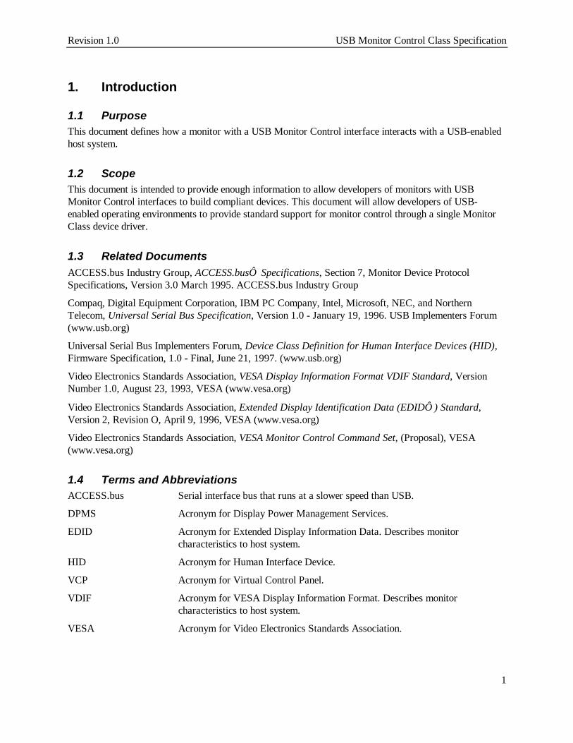
1. Introduction
1.1 PurposeThis document defines how a monitor with a USB Monitor Control interface interacts with a USB-enabledhost system.
1.2 ScopeThis document is intended to provide enough information to allow developers of monitors with USBMonitor Control interfaces to build compliant devices. This document will allow developers of USB-enabled operating environments to provide standard support for monitor control through a single MonitorClass device driver.
1.3 Related DocumentsACCESS.bus Industry Group, ACCESS.bus Specifications, Section 7, Monitor Device ProtocolSpecifications, Version 3.0 March 1995. ACCESS.bus Industry Group
Compaq, Digital Equipment Corporation, IBM PC Company, Intel, Microsoft, NEC, and NorthernTelecom, Universal Serial Bus Specification, Version 1.0 - January 19, 1996. USB Implementers Forum(www.usb.org)
Universal Serial Bus Implementers Forum, Device Class Definition for Human Interface Devices (HID),Firmware Specification, 1.0 - Final, June 21, 1997. (www.usb.org)
Video Electronics Standards Association, VESA Display Information Format VDIF Standard, VersionNumber 1.0, August 23, 1993, VESA (www.vesa.org)
Video Electronics Standards Association, Extended Display Identification Data (EDID ) Standard,Version 2, Revision O, April 9, 1996, VESA (www.vesa.org)
Video Electronics Standards Association, VESA Monitor Control Command Set, (Proposal), VESA(www.vesa.org)
1.4 Terms and AbbreviationsACCESS.bus Serial interface bus that runs at a slower speed than USB.
DPMS Acronym for Display Power Management Services.
EDID Acronym for Extended Display Information Data. Describes monitorcharacteristics to host system.
HID Acronym for Human Interface Device.
VCP Acronym for Virtual Control Panel.
VDIF Acronym for VESA Display Information Format. Describes monitorcharacteristics to host system.
VESA Acronym for Video Electronics Standards Association.

USB Monitor Control Class Specification Revision 1.0
2
2. Management OverviewThe Universal Serial Bus Monitor Control Class focuses on the management and control of monitors. USBis not used to transfer the information actually displayed on the monitor. USB’s available bandwidth is notsufficient for this task.
This specification defines a protocol for communications between monitor devices and host systems usingUSB. This protocol manages typical user controls such as brightness, contrast, size and position, as well asinternal settings used to adjust the performance of the monitor for different video adapter modes. Inaddition, this specification describes how monitor power management is performed through USB.
There are a number of parameters that describe a monitor’s characteristics to a host system. Thisinformation may be used to constrain the supported modes of a video adapter to those that are compatiblewith the monitor. When the host system inquires about these characteristics, the monitor returns theinformation requested. This allows the host environment to determine the monitor type and characteristicswithout end-user intervention.
The protocol of the USB Monitor Control Class has been designed within the constraints imposed by theUSB Device Class Definition for Human Interface Devices (HID) Specification. A monitor is a HIDdevice.
This allows host support for Monitor Class devices to be simpler as they may rely on a HID Class driverfor direct access to their device; the devices need not be concerned with the interaction between the HIDClass driver and lower-system software layers.
This specification builds on previous industry efforts by using reporting formats standardized by the VideoElectronics Standard Association (VESA) and virtual control panel op-codes standardized by theACCESS.bus Industry Group.
Revision 1.0 USB Monitor Control Class Specification
3
3. BackgroundMonitors typically provide a number of controls to allow end-users to adjust monitor performance to anindividual’s preference. When a video adapter changes modes, a monitor may also require adjustment ofthose controls to compensate for changes in the characteristics of the video signal.
The Video Electronics Standard Association (VESA) describes a method of reporting a monitor’s timinginformation to allow video adapters to be optimally programmed. Two standards relating to monitor timinghave been released. The VESA Display Information Format (VDIF) includes descriptive information aboutthe monitor, operational limits, pre-adjusted timings and, optionally, gamma information from a calibrationdevice.
VDIF permits one or more pre-adjusted timings for each operational limit specified and the gamma table, ifpresent, can have a large number of entries. This means the amount of information returned varies in lengthand can actually require several Kbytes of information to be returned by the monitor.
More recently, VESA published another standard reporting format for describing the capabilities of amonitor: the Extended Display Identification Data (EDID ) Standard. This format is more compact.
Having a standard format for the information reported is important, but equally important is how a hostsystem obtains this information. Neither the VDIF or EDID specifications specify how this is to beachieved. Also, the specifications do not describe how the information, if and when delivered, will be used.
VESA did develop two methods of host-to-monitor communications, known as DDC1/2B and DDC1/2AB.The first is a simple application of the Philips I2C protocol for reading VDIF information from the monitor.The second is a superset of the first, and supports the reading of VDIF information and the control of themonitor from a host system. The ACCESS.bus Industry Group, as a part of the ACCESS.busSpecifications, published a section on Monitor Device Protocol Specifications for monitors that arecompliant with VESA DDC1/2AB.
In some systems, VDIF or EDID data may be returned by the video BIOS. This requires a display adaptercapable of communicating with the attached monitor to obtain the necessary information and operatingsystems that attempt to use the information. This specification provides another mechanism for obtainingthis information from the monitor across USB. This is in addition to using USB for monitor control andstatus. Providing BIOS level support for returning VDIF and EDID information is not necessary if youadhere to this specification.
USB Monitor Control Class Specification Revision 1.0
4
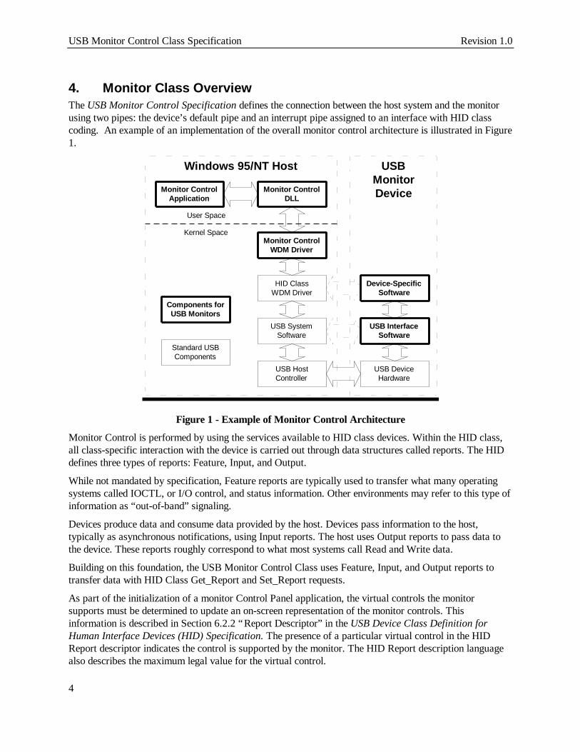
4. Monitor Class OverviewThe USB Monitor Control Specification defines the connection between the host system and the monitorusing two pipes: the device’s default pipe and an interrupt pipe assigned to an interface with HID classcoding. An example of an implementation of the overall monitor control architecture is illustrated in Figure1.
Monitor ControlApplication
Monitor ControlDLL
Monitor ControlWDM Driver
HID ClassWDM Driver
USB SystemSoftware
USB HostController
Device-SpecificSoftware
USB InterfaceSoftware
USB DeviceHardware
USBMonitorDevice
Windows 95/NT Host
Kernel Space
User Space
Components forUSB Monitors
Standard USBComponents
Figure 1 - Example of Monitor Control Architecture
Monitor Control is performed by using the services available to HID class devices. Within the HID class,all class-specific interaction with the device is carried out through data structures called reports. The HIDdefines three types of reports: Feature, Input, and Output.
While not mandated by specification, Feature reports are typically used to transfer what many operatingsystems called IOCTL, or I/O control, and status information. Other environments may refer to this type ofinformation as “out-of-band” signaling.
Devices produce data and consume data provided by the host. Devices pass information to the host,typically as asynchronous notifications, using Input reports. The host uses Output reports to pass data tothe device. These reports roughly correspond to what most systems call Read and Write data.
Building on this foundation, the USB Monitor Control Class uses Feature, Input, and Output reports totransfer data with HID Class Get_Report and Set_Report requests.
As part of the initialization of a monitor Control Panel application, the virtual controls the monitorsupports must be determined to update an on-screen representation of the monitor controls. Thisinformation is described in Section 6.2.2 “Report Descriptor” in the USB Device Class Definition forHuman Interface Devices (HID) Specification. The presence of a particular virtual control in the HIDReport descriptor indicates the control is supported by the monitor. The HID Report description languagealso describes the maximum legal value for the virtual control.

Revision 1.0 USB Monitor Control Class Specification
5
When a video adapter changes the video mode, monitors often require different settings for virtual controlsto deal with differences in the supplied video signal. Monitors typically provide preset values for a numberof recognized video modes. When a particular mode is recognized by the monitor, it automatically changesthe virtual controls to preset values associated with that mode. The end-user may then adjust the individualvirtual controls to tune the performance of the monitor to an individual’s preference.
Some monitors allow end-user customized settings to replace the pre-set values for the selected video mode.When the monitor receives a request from the host to write the Settings control, the monitor saves thecurrent settings of all virtual controls as the values to be used whenever the monitor senses the currentvideo mode.
Monitor control applications should note that not all video modes have a unique set of pre-set values for amonitor’s virtual controls. Writing to the Settings control may result in a change to the values used formore than one video mode. At this time, the USB Monitor Control Class Specification does not providesupport for determining which set of pre-set values is currently selected. Adjustments may only be made tothe currently selected set of pre-set values for virtual controls.
When the monitor receives a request from the host to write ENUM_1 to the Settings virtual control, themonitor saves the current settings of all virtual controls as the values to be used whenever the monitorsenses the current video mode.
Some monitors may allow factory default settings for the currently selected set of pre-sets to be restored. Ifso, the monitor restores factory defaults when a write of ENUM_2 is sent to the Settings virtual control.For compatibility, if this capability is not supported, the monitor simply responds as if it completed therequest successfully.

USB Monitor Control Class Specification Revision 1.0
6
5. Monitor Class ReferenceThis section is intended to be used as a reference for Monitor Descriptors, Requests, and Reports.
5.1 Monitor DescriptorsUSB monitors are HID class devices. Therefore, they use the same set of descriptors as any HID device.These include all of the standard descriptors: device, configuration, interface, endpoint, and stringdescriptors. They also use a HID Descriptor associated with the interface containing the interrupt endpointand a Report Descriptor as defined in the Device Class Definition for Human Interface Devices (HID)Specification.
5.2 Monitor RequestsUSB monitors support standard USB requests, as appropriate for the monitor’s implementation. USBmonitors also utilize the HID class-specific requests Get_Report and Set_Report. USB monitors do not useany of the other HID class-specific requests, for example: Get_Idle, Set_Idle, Get_Protocol, andSet_Protocol.
HID class drivers do not provide any method of providing further extensions to HID class-specific requests.Because the USB monitor driver is intended to use a HID class driver for communications with the USBmonitor device, the USB Monitor Control Class Specification does not have any class-specific requests.Defining such requests would have required that a monitor driver bypass the HID class driver and interactdirectly with the USB system software on the host. Such behavior would violate the spirit of a layeredsoftware architecture.
5.3 Monitor ReportsThis section describes the reports supported by USB Monitor Control Class devices. All reports follow thedefinition of HID class reports of the same type. There are three types of reports:
• Feature
• Input
• Output
All types of reports may be specifically requested through the device’s default pipe using a standard HIDclass request, Get_Report. Feature and Output reports may also be sent to the device using the standardHID class request, Set_Report. Input reports may also be received via the interrupt pipe forasynchronously reporting purposes.
Feature reports are used to get or set monitor device characteristics. Some Feature reports may only beappropriate for device-to-host transfers or get operations. Other Feature reports are used to change theconfiguration of the monitor.
Output reports are used to send commands to a monitor using controls that are write only (for example,Degauss). Input and Feature reports are used to report the current setting of a particular aspect of aconfiguration of a monitor. Controls defined in Feature reports that may be modified by external eventsshould also be defined in an Input report. As previously noted, Input reports may be requested via thedefault pipe or sent to the host by the device when that particular aspect changes.

Revision 1.0 USB Monitor Control Class Specification
7
Within each report type, report IDs are unique. Report IDs may be re-used between report types. Forexample, there is only one Input report that uses ID 0. There may also be a single Feature and a singleOutput report that also uses ID 0. Report IDs are arbitrary and implementation-dependent.
5.3.1 Individual Monitor ReportsThe controls that are contained in a particular report are implementation-dependent. Host-based software,typically a HID class device driver, is responsible for determining which report contains values for aparticular monitor control.
A monitor manufacturer decides how many individual reports their monitor uses. It is possible toimplement a monitor with one Feature report, one Input report, and one Output report. However, it istypically more efficient to provide multiple reports to partition the information exchanged between the hostand the monitor into smaller more cohesive units. For more information, see the USB Device ClassDefinition for Human Interface Devices (HID) Specification.
5.4 Power ManagementUSB Monitors manage power drawn from the bus as defined by the USB Specification (suspend/resume).USB Monitors may implement USB Interface Power Management as described in the USB Common ClassSpecification. USB Monitors implementing USB Interface Power Management control manage power forthe entire display device.
If a USB Monitor has multiple control channels for power management (i.e. DPMS and USB InterfacePower Management), the monitor should adjust power consumption to the lowest power consuming staterequested. For example, if USB Interface Power Management has selected the D1 power state and DPMShas selected the D2 power state, the monitor should be placed in the D2 power state. (For power statedefinitions, see the USB Common Class Specification).
5.5 Top-Level CollectionIn order to identify a HID class device as a monitor, the device’s HID Report Descriptor must contain atop-level collection with a usage of Monitor Control from the USB Monitor Usage Page. For moreinformation, see the USB Device Class Definition for Human Interface Devices (HID) Specification.

USB Monitor Control Class Specification Revision 1.0
8
6. Appendices - Usage PagesUSB Monitors use four usage pages assigned by the HID Class Working Group for usage IDs. The pagesare:
Page Description
0x80 USB Monitor
0x81 USB Enumerated Values
0x82 VESA Virtual Controls
0x83 Reserved
6.1.1 USB Monitor Usage PageThe USB Monitor Usage page contains USB Monitor usage values that are unique to USB connectivity.
Value Virtual Control Description
00h Reserved Reserved for future use.
01h Monitor Control USB Monitor Control HID Device.
02h EDID Information
03h VDIF Information
04h VESA Version The version of the VESA Monitor Command Setspecification used by this device.
If this field is set to zero (0), the monitor uses thevirtual control usage values defined in thisdocument.
If this field is non-zero, it is a Binary-CodedDecimal (BCD) value representing the versionnumber of the VESA Monitor Command Setspecification used to define the monitor’s virtualcontrol and command usage values.
6.2 Monitor Enumerated Values [Usage Page]A number of monitor controls use values that are or may be non-contiguous. For example, by VESAdefinition, an Input Source Selector control has values that range from zero to twenty-eight.
However, many monitors may not implement all of these inputs. If a monitor only provided DB-15HD/VGA1 and S-Video1 inputs, only the enumerated values one and sixteen would be valid.
Due to the nature of the HID class report description language, a defined usage value would typically haveto be created for each value that might be returned. This would require a lot of new usage values to bedefined; it would also require that either VESA change the mapping between constant (usage value) and
Revision 1.0 USB Monitor Control Class Specification
9
meaning, or a separate usage page would have to be assigned to the values returned by every control thatcould have non-contiguous values.
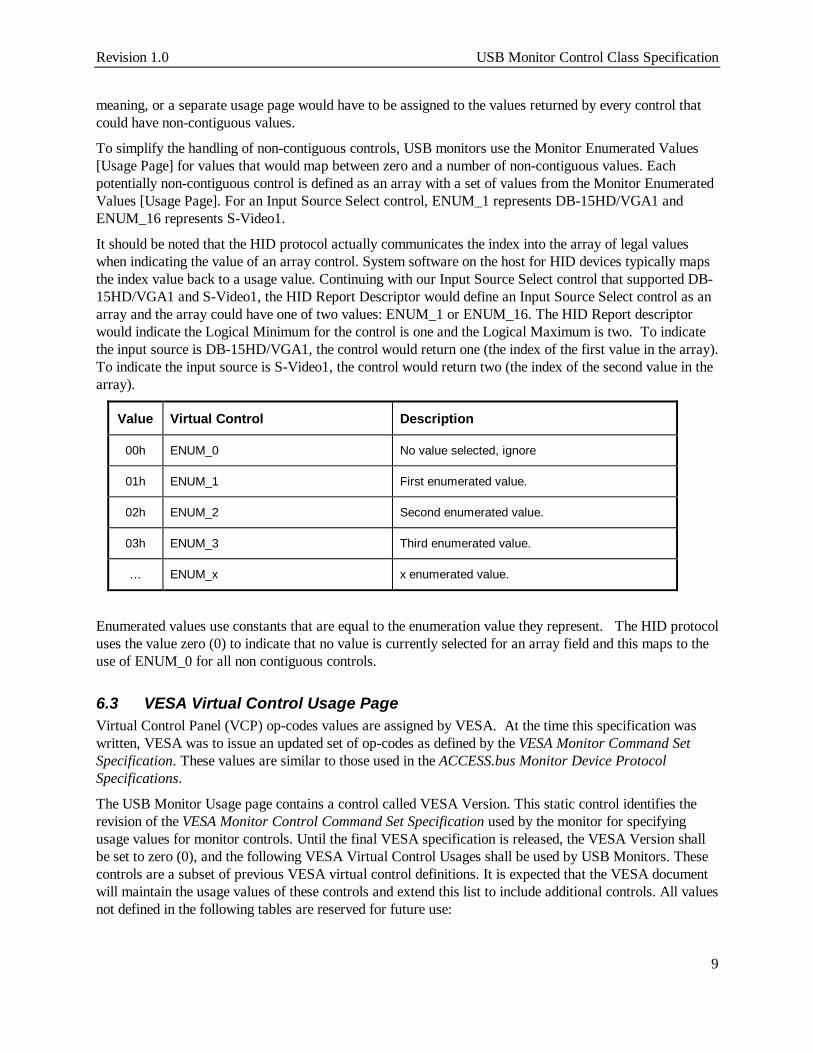
To simplify the handling of non-contiguous controls, USB monitors use the Monitor Enumerated Values[Usage Page] for values that would map between zero and a number of non-contiguous values. Eachpotentially non-contiguous control is defined as an array with a set of values from the Monitor EnumeratedValues [Usage Page]. For an Input Source Select control, ENUM_1 represents DB-15HD/VGA1 andENUM_16 represents S-Video1.
It should be noted that the HID protocol actually communicates the index into the array of legal valueswhen indicating the value of an array control. System software on the host for HID devices typically mapsthe index value back to a usage value. Continuing with our Input Source Select control that supported DB-15HD/VGA1 and S-Video1, the HID Report Descriptor would define an Input Source Select control as anarray and the array could have one of two values: ENUM_1 or ENUM_16. The HID Report descriptorwould indicate the Logical Minimum for the control is one and the Logical Maximum is two. To indicatethe input source is DB-15HD/VGA1, the control would return one (the index of the first value in the array).To indicate the input source is S-Video1, the control would return two (the index of the second value in thearray).
Value Virtual Control Description
00h ENUM_0 No value selected, ignore
01h ENUM_1 First enumerated value.
02h ENUM_2 Second enumerated value.
03h ENUM_3 Third enumerated value.
… ENUM_x x enumerated value.
Enumerated values use constants that are equal to the enumeration value they represent. The HID protocoluses the value zero (0) to indicate that no value is currently selected for an array field and this maps to theuse of ENUM_0 for all non contiguous controls.
6.3 VESA Virtual Control Usage PageVirtual Control Panel (VCP) op-codes values are assigned by VESA. At the time this specification waswritten, VESA was to issue an updated set of op-codes as defined by the VESA Monitor Command SetSpecification. These values are similar to those used in the ACCESS.bus Monitor Device ProtocolSpecifications.
The USB Monitor Usage page contains a control called VESA Version. This static control identifies therevision of the VESA Monitor Control Command Set Specification used by the monitor for specifyingusage values for monitor controls. Until the final VESA specification is released, the VESA Version shallbe set to zero (0), and the following VESA Virtual Control Usages shall be used by USB Monitors. Thesecontrols are a subset of previous VESA virtual control definitions. It is expected that the VESA documentwill maintain the usage values of these controls and extend this list to include additional controls. All valuesnot defined in the following tables are reserved for future use:

USB Monitor Control Class Specification Revision 1.0
10
Contiguous Controls
Value Virtual Control Description
10h Brightness The black level luminance of the display.
12h Contrast The ratio between the maximum and minimumluminance values.
16h Red Video Gain The level of maximum luminance of red pixels.
Setting sensitivity of the RED luminance output.
18h Green Video Gain The level of maximum luminance of green pixels.
1Ah Blue Video Gain The level of maximum luminance of blue pixels.
1Ch Focus Adjusts the apparent spot size.
20h Horizontal Position Moves the image toward the right side of thedisplay.
22h Horizontal Size The distance between the left and right sides ofthe image.
24h Horizontal Pincushion Increasing (decreasing) this value causes theright and left sides of the image to become more(less) convex.
26h Horizontal Pincushion Balance Moves the center section of the image toward theright or left side of the display.
28h Horizontal Misconvergence Increasing (decreasing) this value will shift the redpixels to the right (left) across the image and theblue pixels left (right) across the image withrespect to the green pixels.
2Ah Horizontal Linearity Shifts the density of pixels from the left and rightends to the center of the image.
2Ch Horizontal Linearity Balance Increasing (decreasing) this value shifts thedensity of pixels from the left (right) side to theright (left) side of the image.
30h Vertical Position Increasing (decreasing) this value moves theimage toward the top (bottom) of the display.
32h Vertical Size The distance between the top and bottom of theimage.
34h Vertical Pincushion Increasing (decreasing) this value causes the topand bottom sides of the image to become more(less) convex.
Revision 1.0 USB Monitor Control Class Specification
11
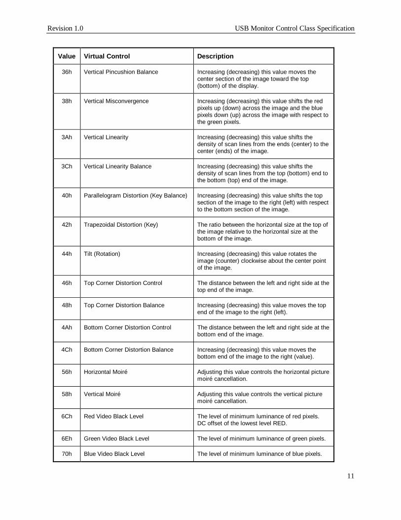
Value Virtual Control Description
36h Vertical Pincushion Balance Increasing (decreasing) this value moves thecenter section of the image toward the top(bottom) of the display.
38h Vertical Misconvergence Increasing (decreasing) this value shifts the redpixels up (down) across the image and the bluepixels down (up) across the image with respect tothe green pixels.
3Ah Vertical Linearity Increasing (decreasing) this value shifts thedensity of scan lines from the ends (center) to thecenter (ends) of the image.
3Ch Vertical Linearity Balance Increasing (decreasing) this value shifts thedensity of scan lines from the top (bottom) end tothe bottom (top) end of the image.
40h Parallelogram Distortion (Key Balance) Increasing (decreasing) this value shifts the topsection of the image to the right (left) with respectto the bottom section of the image.
42h Trapezoidal Distortion (Key) The ratio between the horizontal size at the top ofthe image relative to the horizontal size at thebottom of the image.
44h Tilt (Rotation) Increasing (decreasing) this value rotates theimage (counter) clockwise about the center pointof the image.
46h Top Corner Distortion Control The distance between the left and right side at thetop end of the image.
48h Top Corner Distortion Balance Increasing (decreasing) this value moves the topend of the image to the right (left).
4Ah Bottom Corner Distortion Control The distance between the left and right side at thebottom end of the image.
4Ch Bottom Corner Distortion Balance Increasing (decreasing) this value moves thebottom end of the image to the right (value).
56h Horizontal Moiré Adjusting this value controls the horizontal picturemoiré cancellation.
58h Vertical Moiré Adjusting this value controls the vertical picturemoiré cancellation.
6Ch Red Video Black Level The level of minimum luminance of red pixels.DC offset of the lowest level RED.
6Eh Green Video Black Level The level of minimum luminance of green pixels.
70h Blue Video Black Level The level of minimum luminance of blue pixels.

USB Monitor Control Class Specification Revision 1.0
12
Non-contiguous Controls (Read/Write)
Value Virtual Control Description
5Eh Input Level Select Changing this value chooses a different video input voltage forthe display. Format is reference white above blank, level of sync.below blank:
ENUM_0 None selectedENUM_1 0.700, - 0.300 (1.00 Vpp)ENUM_2 0.714, - 0.286 (1.00 Vpp)ENUM_3 1.000, - 0.400 (1.40 Vpp)ENUM_4 0.700, - 0.000 (0.70 Vpp)
60h Input Source Select Changing this value selects a different video input source:
ENUM_0 None selectedENUM_1 DB-15HD/VGA1ENUM_2 DB-15HD/VGA2ENUM_3 DB-15HD/VGA3ENUM_4 BNC/RGB1ENUM_5 BNC/RGB2ENUM_6 BNC/RGB3ENUM_7 EVC1ENUM_8 EVC2ENUM_9 EVC3ENUM_10 MAC1ENUM_11 MAC2ENUM_12 MAC3ENUM_13 RCA/ Composite Video1ENUM_14 RCA/ Composite Video2ENUM_15 RCA/ Composite Video3ENUM_16 S-Video1ENUM_17 S-Video2ENUM_18 S-Video3ENUM_19 SCART-Composite1ENUM_20 SCART-Composite2ENUM_21 SCART-RGBENUM_22 SCART-S-videoENUM_23 Tuner1ENUM_24 Tuner2ENUM_25 Tuner3ENUM_26 YUV1ENUM_27 YUV2ENUM_28 YUV3
CAh On Screen Display ENUM_0 None selectedENUM_1 OSD is disabled to appearENUM_2 OSD is enabled to appear

Revision 1.0 USB Monitor Control Class Specification
13
Value Virtual Control Description
D4h StereoMode Changing this value selects the video mode with respect to 2D or3D:
ENUM_0 None selectedENUM_1 Mono ModeENUM_2 Enable Field-Sequential Right Eye FirstENUM_3 Enable Field-Sequential Left Eye FirstENUM_4 Enable 2-Way Interleaved Right Eye FirstENUM_5 Enable 2-Way Interleaved Left Eye FirstENUM_6 Enable 4-Way Interleaved,
Display Stereo Buffer 0 (even scan lines)ENUM_7 Enable 4-Way Interleaved,
Display Stereo Buffer 1 (odd scan lines)ENUM_8 Enable Side-by-Side Interleaved
Non-contiguous Controls (Read-only)
A2h Auto Size Center ENUM_0 None selectedENUM_1 DisabledENUM_2 Enabled
A4h Polarity HorizontalSynchronization
ENUM_0 None selectedENUM_1 NegativeENUM_2 Positive
A6h Polarity VerticalSynchronization
ENUM_0 None selectedENUM_1 NegativeENUM_2 Positive
A8h Synchronization Type ENUM_0 None selectedENUM_1 SeparateENUM_2 Digital CompositeENUM_3 Composite on Green
AAh Screen Orientation ENUM_0 None selectedENUM_1 LandscapeENUM_2 Portrait
ACh Horizontal Frequency Horizontal frequency in Hertz
AEh Vertical Frequency Vertical frequency in 0.01 Hertz

USB Monitor Control Class Specification Revision 1.0
14
Non-contiguous Controls (Write-only)
01h Degauss Writing a non-zero value to this control causes the monitor tostart a self-timed degauss cycle. The monitor automaticallycompletes the cycle without further action by the host. If a zerovalue is written to this control, the monitor ignores the write anddoes not start a degauss cycle. The monitor does not alter anyof its other control or status values in response to any write tothis control.
B0h Settings This control saves or restores the settings of a monitor’s virtualcontrols for the current video mode. The controls that areaffected are implementation specific.
ENUM_0 None selected (ignored by monitor)ENUM_1 Store current settingsENUM_2 Restore factory default settingsENUM_3 Restore user-saved settings
Some controls previously defined by VESA were not included in the previous table because it wasunclear whether future VESA specifications would continue to use them (for example, color temperature).Should VESA continue to use such controls or define new controls, that organization has the ability to update theset of defined controls and commands independent of USB by simply including them in the VESA MonitorControl Command Set Specification.
Note

Revision 1.0 USB Monitor Control Class Specification
15
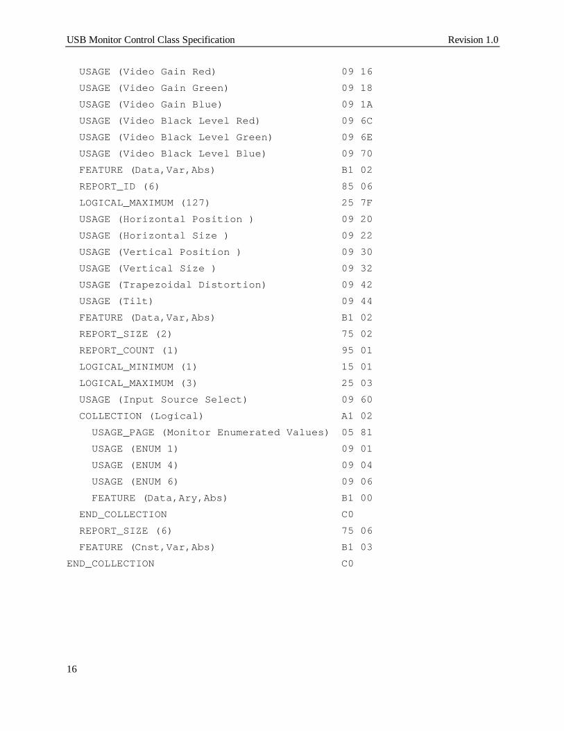
6.5 Example Monitor Report DescriptionsThis appendix provides examples of how the various Monitor reports might be described. These areexamples only. Actual implementation will vary in a number of ways from these examples including (butnot limited to) the order in which data items are defined and the legal ranges for various values.
The HID class supports a single report descriptor. All of the reports described below are contained in asingle HID Report Descriptor.
Please note, the actual values used for item tags are defined by the USB Device Class Definition forHuman Interface Devices (HID) Specification. This example only identifies values that are not item tags.USAGE_PAGE (Monitor) 05 80USAGE (Monitor Control) 09 01COLLECTION (Application) A1 01 REPORT_ID (1) 85 01 LOGICAL_MINIMUM (0) 15 00 LOGICAL_MAXIMUM (255) 26 FF 00 REPORT_SIZE (8) 75 08 REPORT_COUNT (128) 95 80 USAGE (EDID Information) 09 02 FEATURE (Data,Var,Abs,Buf) B2 02 01 REPORT_ID (2) 85 02 REPORT_COUNT (243) 95 F3 USAGE (VDIF Information) 09 03 FEATURE (Data,Var,Abs,Buf) B2 02 01 REPORT_ID (3) 85 03 USAGE_PAGE (VESA Virtual Controls) 05 82 REPORT_SIZE (16) 75 10 REPORT_COUNT (1) 95 01 LOGICAL_MAXIMUM (200) 26 C8 00 USAGE (Brightness) 09 10 FEATURE (Data,Var,Abs) B1 02 REPORT_ID (4) 85 04 LOGICAL_MAXIMUM (100) 25 64 USAGE (Contrast) 09 12 FEATURE (Data,Var,Abs) B1 02 REPORT_ID (5) 85 05 REPORT_COUNT (6) 95 06 LOGICAL_MAXIMUM (255) 26 FF 00
USB Monitor Control Class Specification Revision 1.0
16
USAGE (Video Gain Red) 09 16 USAGE (Video Gain Green) 09 18 USAGE (Video Gain Blue) 09 1A USAGE (Video Black Level Red) 09 6C USAGE (Video Black Level Green) 09 6E USAGE (Video Black Level Blue) 09 70 FEATURE (Data,Var,Abs) B1 02 REPORT_ID (6) 85 06 LOGICAL_MAXIMUM (127) 25 7F USAGE (Horizontal Position ) 09 20 USAGE (Horizontal Size ) 09 22 USAGE (Vertical Position ) 09 30 USAGE (Vertical Size ) 09 32 USAGE (Trapezoidal Distortion) 09 42 USAGE (Tilt) 09 44 FEATURE (Data,Var,Abs) B1 02 REPORT_SIZE (2) 75 02 REPORT_COUNT (1) 95 01 LOGICAL_MINIMUM (1) 15 01 LOGICAL_MAXIMUM (3) 25 03 USAGE (Input Source Select) 09 60 COLLECTION (Logical) A1 02 USAGE_PAGE (Monitor Enumerated Values) 05 81 USAGE (ENUM 1) 09 01 USAGE (ENUM 4) 09 04 USAGE (ENUM 6) 09 06 FEATURE (Data,Ary,Abs) B1 00 END_COLLECTION C0 REPORT_SIZE (6) 75 06 FEATURE (Cnst,Var,Abs) B1 03END_COLLECTION C0