USB / Ethernet interface box USB-MUX-6C6L
24
USB-MUX-6C6L – User guide 16/05/2012 00282805-v2 1 Document confidentiel appartenant à Annecy Electronique S.A.S. Ne peut être diffusé, copié intégralement ou en partie sans autorisation expresse préalable USB / Ethernet interface box USB-MUX-6C6L User Guide
Transcript of USB / Ethernet interface box USB-MUX-6C6L

USB-MUX-6C6L – User guide
16/05/2012 00282805-v2 1
Document confidentiel appartenant à Annecy Electronique S.A.S. Ne peut être diffusé, copié intégralement ou en partie sans autorisation expresse préalable
USB / Ethernet interface box
USB-MUX-6C6L
User Guide

USB-MUX-6C6L – User guide
16/05/2012 00282805-v2 2
Document confidentiel appartenant à Annecy Electronique S.A.S. Ne peut être diffusé, copié intégralement ou en partie sans autorisation expresse préalable
SUMMARY
1. Aim of this document and bibliography ..................................................... 4
1.1. Aim .................................................................................................................................. 4
1.2. Bibliography .................................................................................................................... 4
2. Presentation .............................................................................................. 5
2.1. General presentation ...................................................................................................... 5
2.2. Synoptic .......................................................................................................................... 6
2.3. Main characteristics of the CAN connection .................................................................. 7
Protocol controller: INFINEON MULTICAN......................................................................... 7
High speed line interface: NXP TJA 1040 ........................................................................... 7
Low speed line interface: NXP TJA1055 ............................................................................. 7
Single wire line interface: FREESCALE MCZ33897 .............................................................. 8
2.4. Main characteristics of the KWP2000 connection ......................................................... 8
Line interface: tester mode ................................................................................................ 8
2.5. Main characteristics of the LIN connection .................................................................... 9
Line interface : FREESCALE MC33661 ................................................................................ 9
2.6. Characteristics of digital inputs .................................................................................... 10
3. Technical specifications ............................................................................ 11
3.1. Technical characteristics ............................................................................................... 11
4. Configuration ........................................................................................... 12
4.1. DB15 « I / O » connector .............................................................................................. 12
4.2. « DE9 CAN 1 / K-LIN 1 » to « CAN6 / K-LIN6 » DE9 connectors .................................... 12
4.3. « DE9 IOIOI » DE9 connector ........................................................................................ 13
4.4. USB connector .............................................................................................................. 13
4.5. Ethernet connector ....................................................................................................... 13
4.6. External power supply connector ................................................................................. 13
4.7. LEDs ............................................................................................................................... 14
4.7.1. Power ............................................................................................................... 14
4.7.2. Status ................................................................................................................ 14
4.7.5. USB ................................................................................................................... 14
4.7.9. Ethernet ............................................................................................................ 15
USB-MUX-6C6L – User guide
16/05/2012 00282805-v2 3
Document confidentiel appartenant à Annecy Electronique S.A.S. Ne peut être diffusé, copié intégralement ou en partie sans autorisation expresse préalable
5. Drivers ...................................................................................................... 16
5.1. Drivers history ............................................................................................................... 16
5.1.1. USB Drivers ....................................................................................................... 16
5.1.1.1. Windriver drivers .............................................................................................. 16
5.1.1.2. Exxotest v1.x and v2.x drivers .......................................................................... 16
5.1.2. PCI drivers ......................................................................................................... 17
5.2. Warning ........................................................................................................................ 18
5.3. Installation .................................................................................................................... 19
5.3.1. Installation goal ................................................................................................ 19
5.3.2. Warning ............................................................................................................ 19
5.3.3. Driver installation and applications update ..................................................... 19
5.3.4. Execution of the installation file ...................................................................... 20
5.4. Technical support ......................................................................................................... 23
Successive editions list .................................................................................. 24

USB-MUX-6C6L – User guide
16/05/2012 00282805-v2 4
Document confidentiel appartenant à Annecy Electronique S.A.S. Ne peut être diffusé, copié intégralement ou en partie sans autorisation expresse préalable
1. Aim of this document and bibliography
1.1. Aim
The aim of this document is to give the user the information required to install and set up the case USB-MUX-4C4L.
1.2. Bibliography
NXP : TJA1040 High speed CAN transceiver– data sheet NXP : TJA1055 Enhanced fault-tolerant CAN transceiver – data sheet FREESCALE : MCZ33897 Single Wire CAN Transceiver – data sheet FREESCALE : MC33661 LIN Enhanced Physical Interface – data sheet WIZNET : W5300 10/100 Ethernet controller – data sheet

USB-MUX-6C6L – User guide
16/05/2012 00282805-v2 5
Document confidentiel appartenant à Annecy Electronique S.A.S. Ne peut être diffusé, copié intégralement ou en partie sans autorisation expresse préalable
2. Presentation
2.1. General presentation
The USB-MUX-6C6L is a USB/Ethernet 2nd generation box from the EXXOTEST® « Communication Networks Expertise Systems » products range. allows to interface a PC type computer to a CAN high speed, CAN low speed / fault tolerant, CAN single wire and LIN bus through USB or Ethernet ; it also proposes 14 digital / analog inputs, 6 ISO9141 L / digital outputs and 6 digital / PWM outputs. Available channels:
6 x CAN high speed (Norme ISO 11898) or CAN low speed – fault tolerant or CAN single wire (set up by software) channels
6 x LIN master or slave or ISO9141 (K) channels (set up by software) 14 x analog 0-32V or digital inputs 6 x ISO9141 (L) or digital outputs and 6 x digital/PWM outputs 1µs clock for events dating
All these channels can be used simultaneously. This box is directly powered by its USB port, or by an external 110/220v – 50/60Hz adapter in case the USB port power supply is not sufficient Operating the Ethernet link needs an external power supply. When the box USB port is connected, the Ethernet feature is automatically deactivated.
USB-MUX-6C6L – User guide
16/05/2012 00282805-v2 6
Document confidentiel appartenant à Annecy Electronique S.A.S. Ne peut être diffusé, copié intégralement ou en partie sans autorisation expresse préalable
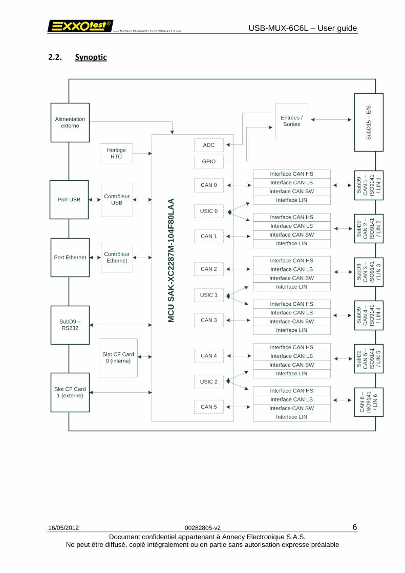
2.2. Synoptic
Alimentation
externe
Port USB
Port Ethernet
SubD9 –
RS232
Su
bD
9
CA
N 1
–
ISO
91
41
/ L
IN 1
Slot CF Card
1 (externe)
Su
bD
9
CA
N 2
–
ISO
91
41
/ L
IN 2
Su
bD
9
CA
N 3
–
ISO
91
41
/ L
IN 3
Su
bD
9
CA
N 4
–
ISO
91
41
/ L
IN 4
Su
bD
9
CA
N 5
–
ISO
91
41
/ L
IN 5
CA
N 6
–
ISO
91
41
/ L
IN 6
Su
bD
15
– E
/S
Interface CAN HS
Interface CAN LS
Interface CAN SW
Interface LIN
Interface CAN HS
Interface CAN SW
Interface LIN
Interface CAN HS
Interface CAN LS
Interface CAN SW
Interface LIN
Interface CAN HS
Interface CAN LS
Interface CAN SW
Interface LIN
Interface CAN HS
Interface CAN LS
Interface CAN SW
Interface LIN
Interface CAN HS
Interface CAN LS
Interface CAN SW
Interface LIN
CAN 0
CAN 1
USIC 0
CAN 2
CAN 3
USIC 1
CAN 4
CAN 5
USIC 2
Contrôleur
USB
Contrôleur
Ethernet
Horloge
RTC
Entrées /
Sorties
MC
U S
AK
-XC
22
87M
-10
4F
80L
AA
ADC
GPIO
Interface CAN LS
Slot CF Card
0 (interne)
USB-MUX-6C6L – User guide
16/05/2012 00282805-v2 7
Document confidentiel appartenant à Annecy Electronique S.A.S. Ne peut être diffusé, copié intégralement ou en partie sans autorisation expresse préalable
2.3. Main characteristics of the CAN connection
Protocol controller: INFINEON MULTICAN
- Standard CAN 2.0B - Standard identifier 11 bits; extended 29 bits - Transmission / reception of data up to 8 bytes - Request for distant transmission (RTR) - Baud rate up to 1 Mbit/sec - Spy mode (no acknowledgement or error frame) - Reading of counters of internal errors - Detailed information in case of bus error
High speed line interface: NXP TJA 1040
- ISO 11898–24V standard - Baud rate up to 1 Mbits/sec - Connection up to 110 stations sur le bus - Transmission in differential mode - Short-circuit to ground and battery > 24V - Termination resistors set up by software
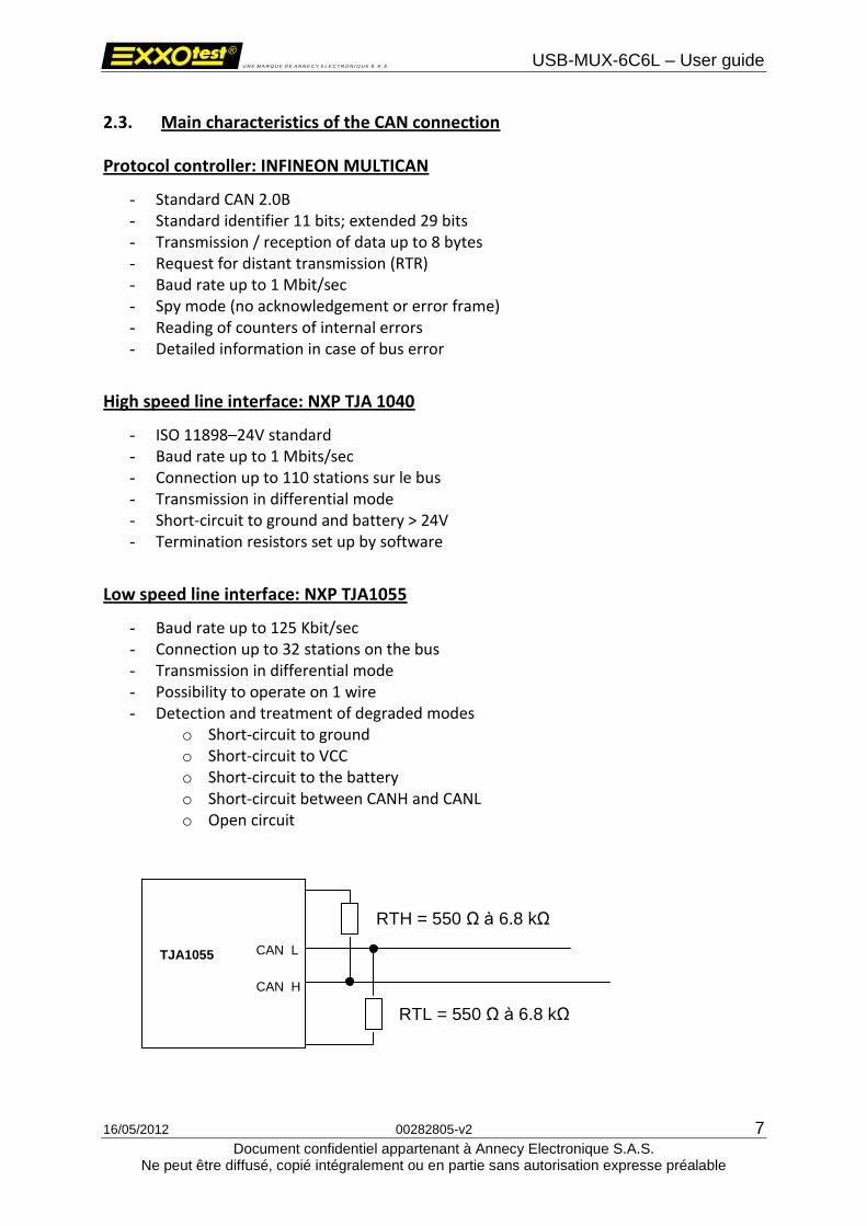
Low speed line interface: NXP TJA1055
- Baud rate up to 125 Kbit/sec - Connection up to 32 stations on the bus - Transmission in differential mode - Possibility to operate on 1 wire - Detection and treatment of degraded modes
o Short-circuit to ground o Short-circuit to VCC o Short-circuit to the battery o Short-circuit between CANH and CANL o Open circuit
CAN_H
CAN_L TJA1055
RTH = 550 Ω à 6.8 kΩ
RTL = 550 Ω à 6.8 kΩ
USB-MUX-6C6L – User guide
16/05/2012 00282805-v2 8
Document confidentiel appartenant à Annecy Electronique S.A.S. Ne peut être diffusé, copié intégralement ou en partie sans autorisation expresse préalable
Single wire line interface: FREESCALE MCZ33897
- Baud rate up to 33 Kbit/sec - Connection up to 32 stations on the bus - Transmission over 1 wire
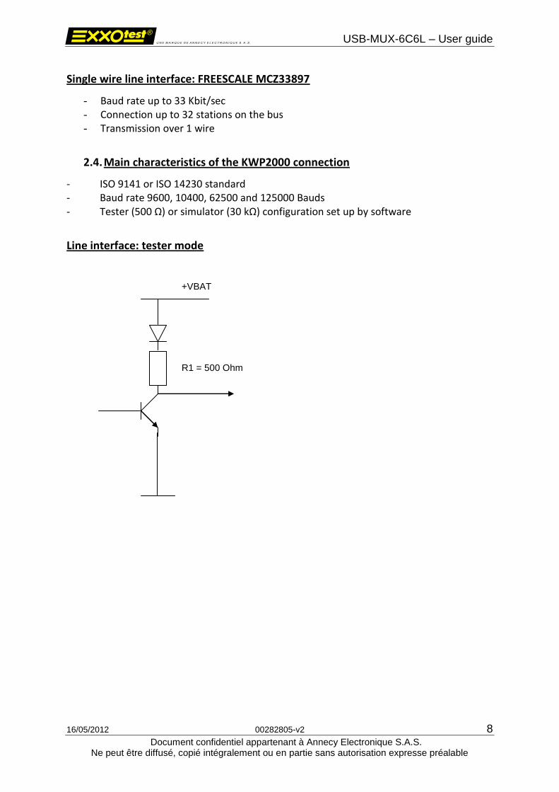
2.4. Main characteristics of the KWP2000 connection
- ISO 9141 or ISO 14230 standard - Baud rate 9600, 10400, 62500 and 125000 Bauds - Tester (500 Ω) or simulator (30 kΩ) configuration set up by software
Line interface: tester mode
+VBAT
R1 = 500 Ohm
USB-MUX-6C6L – User guide
16/05/2012 00282805-v2 9
Document confidentiel appartenant à Annecy Electronique S.A.S. Ne peut être diffusé, copié intégralement ou en partie sans autorisation expresse préalable
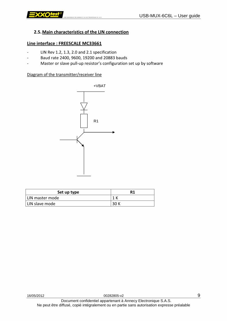
2.5. Main characteristics of the LIN connection
Line interface : FREESCALE MC33661
- LIN Rev 1.2, 1.3, 2.0 and 2.1 specification - Baud rate 2400, 9600, 19200 and 20883 bauds - Master or slave pull-up resistor’s configuration set up by software Diagram of the transmitter/receiver line
Set up type R1
LIN master mode 1 K
LIN slave mode 30 K
+VBAT
R1

USB-MUX-6C6L – User guide
16/05/2012 00282805-v2 10
Document confidentiel appartenant à Annecy Electronique S.A.S. Ne peut être diffusé, copié intégralement ou en partie sans autorisation expresse préalable
2.6. Characteristics of digital inputs
Diagram of inputs
Diagram of outputs
Connector input
+5V
GND
30 k ohms
62 ohms
GND
Connector Output
USB-MUX-6C6L – User guide
16/05/2012 00282805-v2 11
Document confidentiel appartenant à Annecy Electronique S.A.S. Ne peut être diffusé, copié intégralement ou en partie sans autorisation expresse préalable
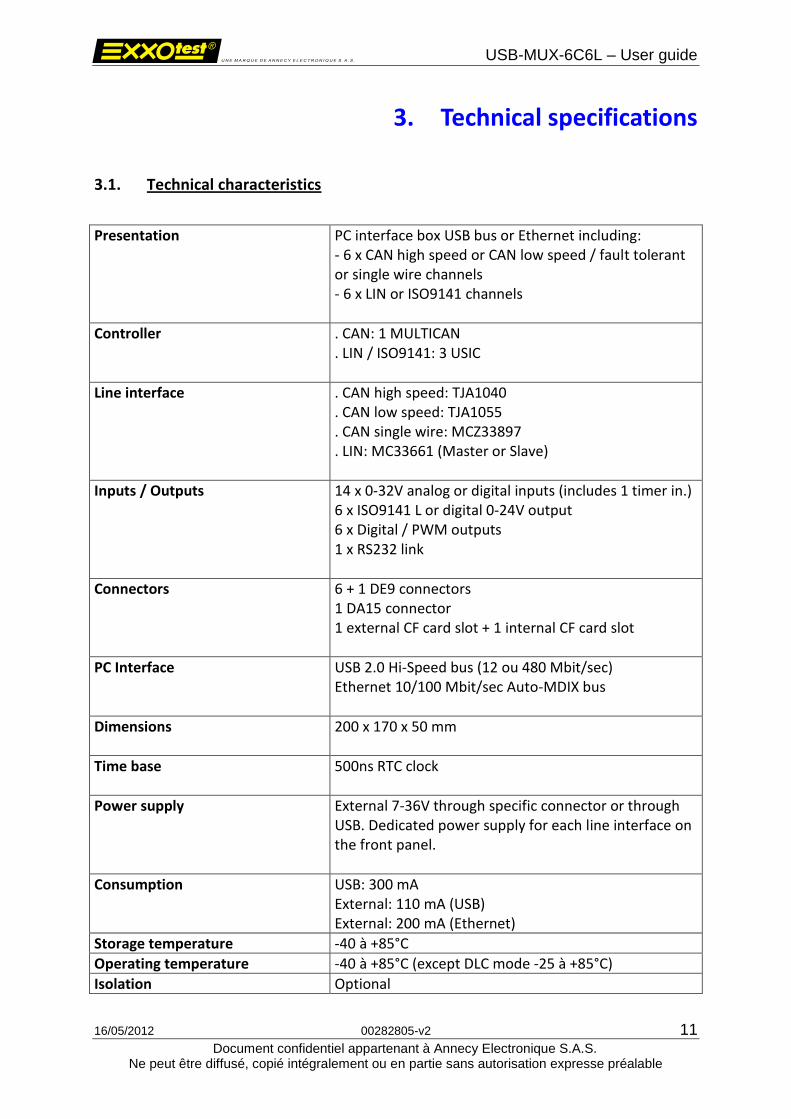
3. Technical specifications
3.1. Technical characteristics
Presentation PC interface box USB bus or Ethernet including: - 6 x CAN high speed or CAN low speed / fault tolerant or single wire channels - 6 x LIN or ISO9141 channels
Controller . CAN: 1 MULTICAN . LIN / ISO9141: 3 USIC
Line interface . CAN high speed: TJA1040 . CAN low speed: TJA1055 . CAN single wire: MCZ33897 . LIN: MC33661 (Master or Slave)
Inputs / Outputs 14 x 0-32V analog or digital inputs (includes 1 timer in.) 6 x ISO9141 L or digital 0-24V output 6 x Digital / PWM outputs 1 x RS232 link
Connectors 6 + 1 DE9 connectors 1 DA15 connector 1 external CF card slot + 1 internal CF card slot
PC Interface USB 2.0 Hi-Speed bus (12 ou 480 Mbit/sec) Ethernet 10/100 Mbit/sec Auto-MDIX bus
Dimensions 200 x 170 x 50 mm
Time base 500ns RTC clock
Power supply External 7-36V through specific connector or through USB. Dedicated power supply for each line interface on the front panel.
Consumption USB: 300 mA External: 110 mA (USB) External: 200 mA (Ethernet)
Storage temperature -40 à +85°C
Operating temperature -40 à +85°C (except DLC mode -25 à +85°C)
Isolation Optional
USB-MUX-6C6L – User guide
16/05/2012 00282805-v2 12
Document confidentiel appartenant à Annecy Electronique S.A.S. Ne peut être diffusé, copié intégralement ou en partie sans autorisation expresse préalable
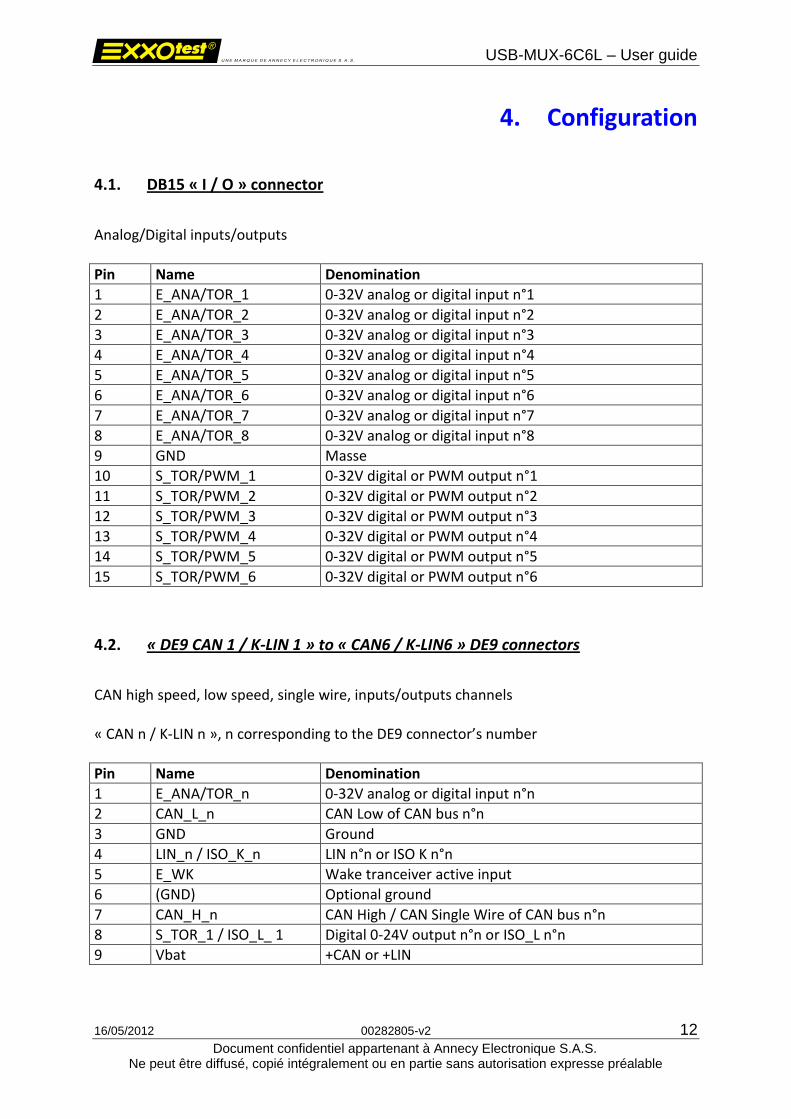
4. Configuration
4.1. DB15 « I / O » connector
Analog/Digital inputs/outputs
Pin Name Denomination
1 E_ANA/TOR_1 0-32V analog or digital input n°1
2 E_ANA/TOR_2 0-32V analog or digital input n°2
3 E_ANA/TOR_3 0-32V analog or digital input n°3
4 E_ANA/TOR_4 0-32V analog or digital input n°4
5 E_ANA/TOR_5 0-32V analog or digital input n°5
6 E_ANA/TOR_6 0-32V analog or digital input n°6
7 E_ANA/TOR_7 0-32V analog or digital input n°7
8 E_ANA/TOR_8 0-32V analog or digital input n°8
9 GND Masse
10 S_TOR/PWM_1 0-32V digital or PWM output n°1
11 S_TOR/PWM_2 0-32V digital or PWM output n°2
12 S_TOR/PWM_3 0-32V digital or PWM output n°3
13 S_TOR/PWM_4 0-32V digital or PWM output n°4
14 S_TOR/PWM_5 0-32V digital or PWM output n°5
15 S_TOR/PWM_6 0-32V digital or PWM output n°6
4.2. « DE9 CAN 1 / K-LIN 1 » to « CAN6 / K-LIN6 » DE9 connectors
CAN high speed, low speed, single wire, inputs/outputs channels « CAN n / K-LIN n », n corresponding to the DE9 connector’s number
Pin Name Denomination
1 E_ANA/TOR_n 0-32V analog or digital input n°n
2 CAN_L_n CAN Low of CAN bus n°n
3 GND Ground
4 LIN_n / ISO_K_n LIN n°n or ISO K n°n
5 E_WK Wake tranceiver active input
6 (GND) Optional ground
7 CAN_H_n CAN High / CAN Single Wire of CAN bus n°n
8 S_TOR_1 / ISO_L_ 1 Digital 0-24V output n°n or ISO_L n°n
9 Vbat +CAN or +LIN
USB-MUX-6C6L – User guide
16/05/2012 00282805-v2 13
Document confidentiel appartenant à Annecy Electronique S.A.S. Ne peut être diffusé, copié intégralement ou en partie sans autorisation expresse préalable
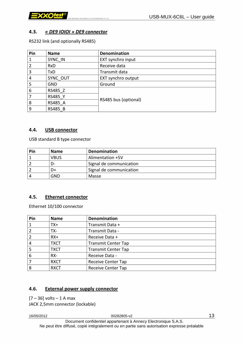
4.3. « DE9 IOIOI » DE9 connector
RS232 link (and optionally RS485)
Pin Name Denomination
1 SYNC_IN EXT synchro input
2 RxD Receive data
3 TxD Transmit data
4 SYNC_OUT EXT synchro output
5 GND Ground
6 RS485_Z
RS485 bus (optional) 7 RS485_Y
8 RS485_A
9 RS485_B
4.4. USB connector
USB standard B type connector
Pin Name Denomination
1 VBUS Alimentation +5V
2 D- Signal de communication
2 D+ Signal de communication
4 GND Masse
4.5. Ethernet connector
Ethernet 10/100 connector
Pin Name Denomination
1 TX+ Transmit Data +
2 TX- Transmit Data -
2 RX+ Receive Data +
4 TXCT Transmit Center Tap
5 TXCT Transmit Center Tap
6 RX- Receive Data -
7 RXCT Receive Center Tap
8 RXCT Receive Center Tap
4.6. External power supply connector
[7 – 36] volts – 1 A max JACK 2,5mm connector (lockable)
USB-MUX-6C6L – User guide
16/05/2012 00282805-v2 14
Document confidentiel appartenant à Annecy Electronique S.A.S. Ne peut être diffusé, copié intégralement ou en partie sans autorisation expresse préalable
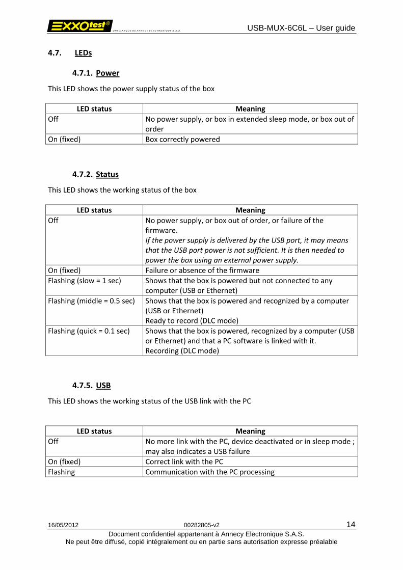
4.7. LEDs
4.7.1. Power
This LED shows the power supply status of the box
LED status Meaning
Off No power supply, or box in extended sleep mode, or box out of order
On (fixed) Box correctly powered
4.7.2. Status
This LED shows the working status of the box
LED status Meaning
Off No power supply, or box out of order, or failure of the firmware. If the power supply is delivered by the USB port, it may means that the USB port power is not sufficient. It is then needed to power the box using an external power supply.
On (fixed) Failure or absence of the firmware
Flashing (slow = 1 sec) Shows that the box is powered but not connected to any computer (USB or Ethernet)
Flashing (middle = 0.5 sec) Shows that the box is powered and recognized by a computer (USB or Ethernet) Ready to record (DLC mode)
Flashing (quick = 0.1 sec) Shows that the box is powered, recognized by a computer (USB or Ethernet) and that a PC software is linked with it. Recording (DLC mode)
4.7.5. USB
This LED shows the working status of the USB link with the PC
LED status Meaning
Off No more link with the PC, device deactivated or in sleep mode ; may also indicates a USB failure
On (fixed) Correct link with the PC
Flashing Communication with the PC processing
USB-MUX-6C6L – User guide
16/05/2012 00282805-v2 15
Document confidentiel appartenant à Annecy Electronique S.A.S. Ne peut être diffusé, copié intégralement ou en partie sans autorisation expresse préalable
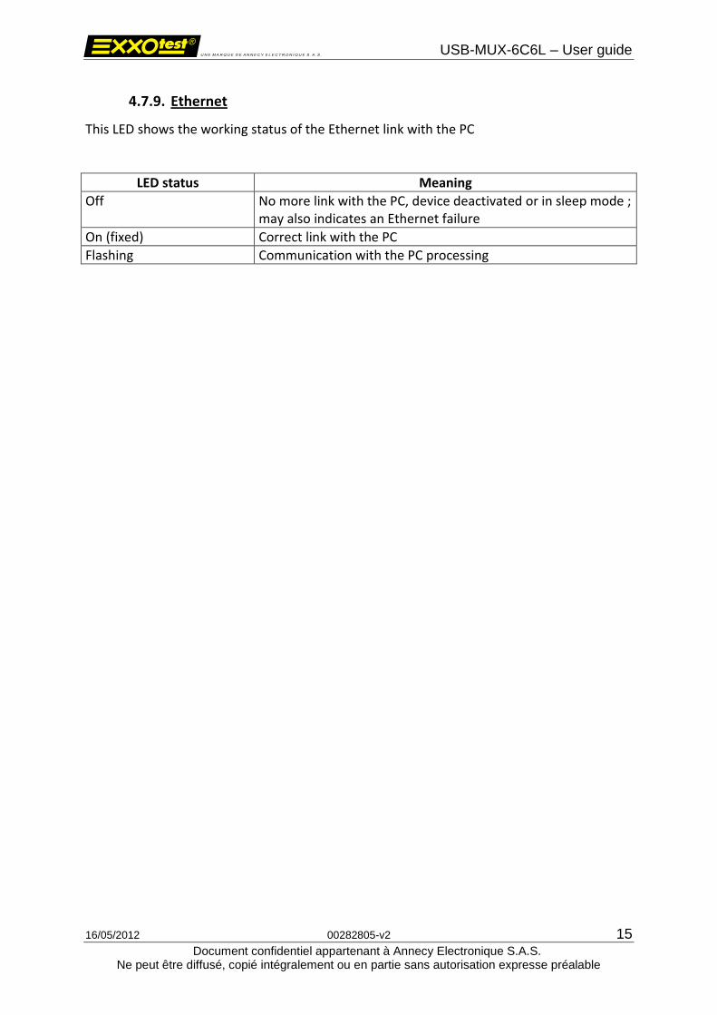
4.7.9. Ethernet
This LED shows the working status of the Ethernet link with the PC
LED status Meaning
Off No more link with the PC, device deactivated or in sleep mode ; may also indicates an Ethernet failure
On (fixed) Correct link with the PC
Flashing Communication with the PC processing

USB-MUX-6C6L – User guide
16/05/2012 00282805-v2 16
Document confidentiel appartenant à Annecy Electronique S.A.S. Ne peut être diffusé, copié intégralement ou en partie sans autorisation expresse préalable
5. Drivers 5.1. Drivers history
5.1.1. USB Drivers
Until now, two drivers allowed the installation of EXXOTEST® USB interfaces
o The 1st one, based on a proprietary development kit (JUNGO), named WINDRIVER in our applications, is now obsolete and its support will be interrupted on next March 1st 2012.
o The 2nd one, based on a Microsoft development kit, named EXXOTEST or EXXOTEST_USB in our applications replaces now the 1st one.
Both of them are supported by a same “generic” software library “MUXDLL.dll” since its 6.1.7 version.
5.1.1.1. Windriver drivers
« Windriver » is the historical « Jungo » driver used since the first EXXOTEST® hardware and software developments. It is now obsolete and its support will be interrupted on next March 1st 2012.
5.1.1.2. Exxotest v1.x and v2.x drivers
The development of the “Exxotest” driver was justified by the needs of performances which were not covered by the “Windriver “ version and by the will of ANNECY ELECTRONIQUE to fully master the scalability of its actual and next generations of MUX interfaces. Again in a way of performance, especially justified by the need to offer a driver version compatible with 64bits Windows OS, the Exxotest driver has undergone a major overhaul in 2011 to reach a version now identified 2.x
USB-MUX-6C6L – User guide
16/05/2012 00282805-v2 17
Document confidentiel appartenant à Annecy Electronique S.A.S. Ne peut être diffusé, copié intégralement ou en partie sans autorisation expresse préalable
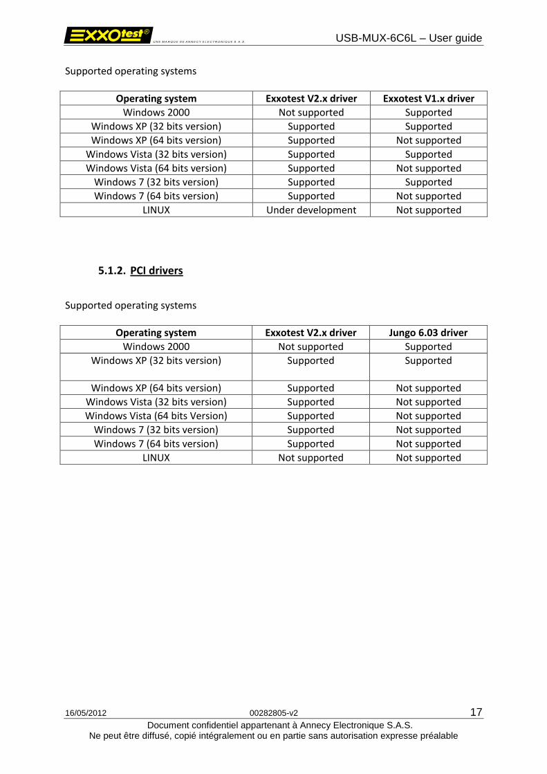
Supported operating systems
Operating system Exxotest V2.x driver Exxotest V1.x driver
Windows 2000 Not supported Supported
Windows XP (32 bits version) Supported Supported
Windows XP (64 bits version) Supported Not supported
Windows Vista (32 bits version) Supported Supported
Windows Vista (64 bits version) Supported Not supported
Windows 7 (32 bits version) Supported Supported
Windows 7 (64 bits version) Supported Not supported
LINUX Under development Not supported
5.1.2. PCI drivers
Supported operating systems
Operating system Exxotest V2.x driver Jungo 6.03 driver
Windows 2000 Not supported Supported
Windows XP (32 bits version)
Supported Supported
Windows XP (64 bits version) Supported Not supported
Windows Vista (32 bits version) Supported Not supported
Windows Vista (64 bits Version) Supported Not supported
Windows 7 (32 bits version) Supported Not supported
Windows 7 (64 bits version) Supported Not supported
LINUX Not supported Not supported

USB-MUX-6C6L – User guide
16/05/2012 00282805-v2 18
Document confidentiel appartenant à Annecy Electronique S.A.S. Ne peut être diffusé, copié intégralement ou en partie sans autorisation expresse préalable
5.2. Warning
This new generation of drivers covering all XP to Seven, 32 and 64 bits Windows operating systems for USB and 2000 to XP 32 bits Windows operating systems for PCI, is now available on the “downloads” webpage of www.exxotest.com and in our “KIT CD MUX” in the form of an utility named: « EXXOTEST® Driver Kit and utilities » All EXXOTEST® applications and utilities available on the Exxotest downloads webpage of and in our “KIT CD MUX” have been updated to run optimally with this new generation of drivers:
o MUXTRACE EXPERT – 4.86 version or higher o DLC / DLC Light – 1.19 version or higher o MUXSERVER – 1.25 version or higher o USBMAJ – 2.13 version or higher o DCP – 1.14 version or higher
En l'absence d'information ou de fourniture de leur part de ces nouveaux pilotes, nous vous recommandons de poursuivre l'utilisation du pilote USB EXXOTEST v1.47 (Utilitaire d’installation USB Driver Kit 1.47).
If you do use EXXOTEST® communication interfaces with third party applications (car manufacturer, component manufacturer, test bench, …), you should ensure that the designers and / or suppliers of these applications have approved the use of these new drivers and updated their applications accordingly. In the absence of information of providing of these new drivers from them side, we recommend the continued use of the Exxotest driver v1.47 (USB Driver Kit 1.47 installer)
USB-MUX-6C6L – User guide
16/05/2012 00282805-v2 19
Document confidentiel appartenant à Annecy Electronique S.A.S. Ne peut être diffusé, copié intégralement ou en partie sans autorisation expresse préalable
5.3. Installation
5.3.1. Installation goal
The new driver installation goal is to improve the performances of applications working with EXXOTEST® card and interfaces through USB and PCI buses.
5.3.2. Warning
To support this update, any application which is not provided by Annecy Electronique and which works with Exxotest card or interface (proprietary application) must realize a “dynamic load” of the software library or being recompiled with this new library.
You are strongly advised to check with people who develop these applications before performing this driver update.
5.3.3. Driver installation and applications update
The driver update will be performed accordingly to following steps:
- Either from the KIT CD MUX (if 2012 version or higher) that came with your EXXOTEST® card or interface, or from a downloaded version from the www.exxotest.com downloads webpage, execute the installation file :
« Exxotest_MUX_driver_kit_2.x.x »
- EXXOTEST® applications update:
o MUXTRACE EXPERT – 4.86 version or higher o DLC / DLC Light – 1.19 version or higher o MUXSERVER – 1.25 version or higher o USBMAJ – 2.13 version or higher o DCP – 1.14 version or higher
- Update of the software libraries (MUXDLL.dll) associated to your proprietary (non EXXOTEST®) working with EXXOTEST® card or interfaces. Attention: Check with the supplier or service responsible for distributing these applications to the good compatibility of these applications before installing the EXXOTEST® Driver Kit and utilities v2.xx
USB-MUX-6C6L – User guide
16/05/2012 00282805-v2 20
Document confidentiel appartenant à Annecy Electronique S.A.S. Ne peut être diffusé, copié intégralement ou en partie sans autorisation expresse préalable
- Update of the firmware of your EXXOTEST® interface (USB only) using the USBMAJ utility version 2.13 or higher.
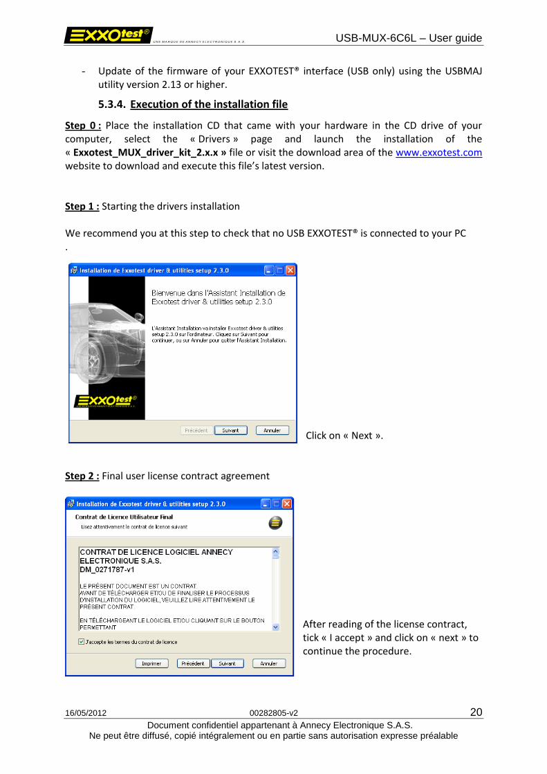
5.3.4. Execution of the installation file
Step 0 : Place the installation CD that came with your hardware in the CD drive of your computer, select the « Drivers » page and launch the installation of the « Exxotest_MUX_driver_kit_2.x.x » file or visit the download area of the www.exxotest.com website to download and execute this file’s latest version. Step 1 : Starting the drivers installation We recommend you at this step to check that no USB EXXOTEST® is connected to your PC .
Click on « Next ».
Step 2 : Final user license contract agreement
After reading of the license contract, tick « I accept » and click on « next » to continue the procedure.

USB-MUX-6C6L – User guide
16/05/2012 00282805-v2 21
Document confidentiel appartenant à Annecy Electronique S.A.S. Ne peut être diffusé, copié intégralement ou en partie sans autorisation expresse préalable
Step 3 : Installation options selection
Select or unselect the options to be installed accordingly to your needs. We therefore recommend you to keep the default configuration. Click on « Next » to continue.
WARNING: PCI cards users, the PCI driver installation is not activated in the default configuration. WE then recommend you to proceed as described here below. Etape 3 bis : PCI card users only
Click on the button in front of “PCI driver installation”, select the option and click on “Next” to continue.
USB-MUX-6C6L – User guide
16/05/2012 00282805-v2 22
Document confidentiel appartenant à Annecy Electronique S.A.S. Ne peut être diffusé, copié intégralement ou en partie sans autorisation expresse préalable
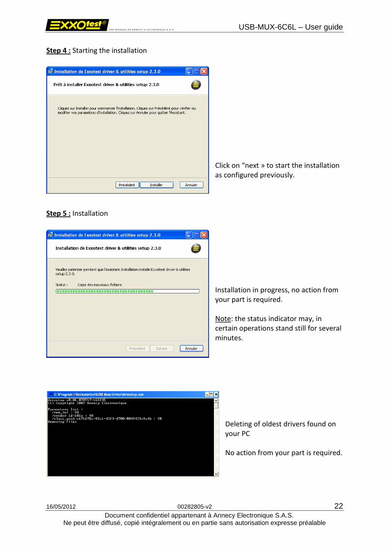
Step 4 : Starting the installation
Click on “next » to start the installation as configured previously.
Step 5 : Installation
Installation in progress, no action from your part is required. Note: the status indicator may, in certain operations stand still for several minutes.
Deleting of oldest drivers found on your PC No action from your part is required.
USB-MUX-6C6L – User guide
16/05/2012 00282805-v2 23
Document confidentiel appartenant à Annecy Electronique S.A.S. Ne peut être diffusé, copié intégralement ou en partie sans autorisation expresse préalable
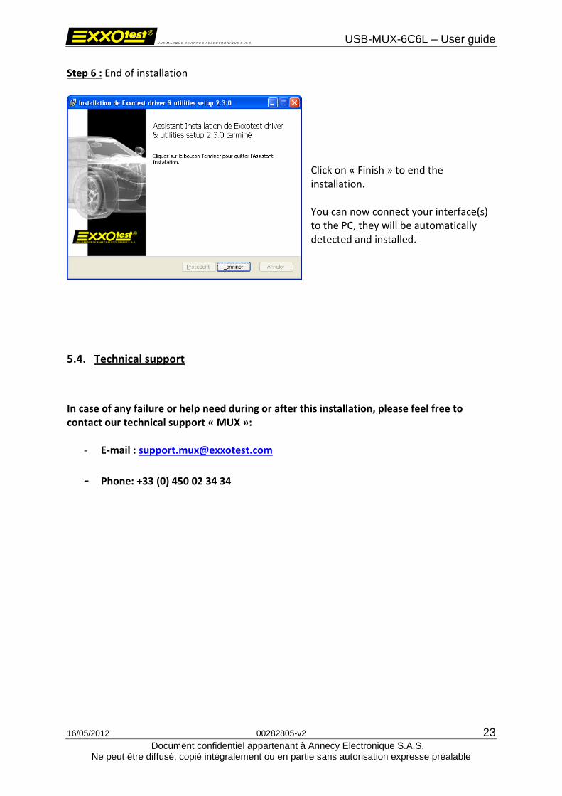
Step 6 : End of installation
Click on « Finish » to end the installation. You can now connect your interface(s) to the PC, they will be automatically detected and installed.
5.4. Technical support
In case of any failure or help need during or after this installation, please feel free to contact our technical support « MUX »:
- E-mail : [email protected]
- Phone: +33 (0) 450 02 34 34
USB-MUX-6C6L – User guide
16/05/2012 00282805-v2 24
Document confidentiel appartenant à Annecy Electronique S.A.S. Ne peut être diffusé, copié intégralement ou en partie sans autorisation expresse préalable
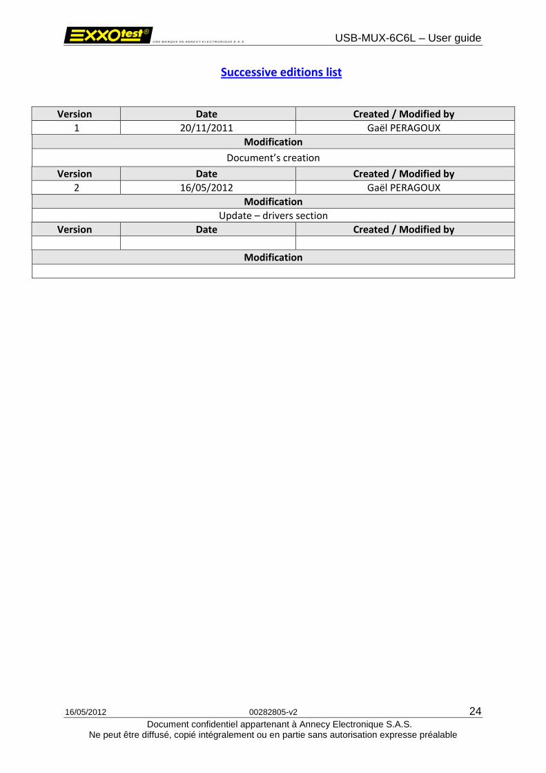
Successive editions list
Version Date Created / Modified by
1 20/11/2011 Gaël PERAGOUX
Modification
Document’s creation
Version Date Created / Modified by
2 16/05/2012 Gaël PERAGOUX
Modification
Update – drivers section
Version Date Created / Modified by
Modification