Usability Aspects On Industrial ABB Robot Calibration With ... · Usability Aspects On Industrial...
61
Usability Aspects On Industrial ABB Robot Calibration With A Focus On TCP And Work Object Calibration Dilip Kota April 1, 2007 Master’s Thesis in Computing Science, 20 credits Supervisor at ABB Corporate Research: Ivan Lundberg Supervisor at Ume˚ a University: Anders Broberg Examiner: Per Lindstr¨ om Ume ˚ a University Department of Computing Science SE-901 87 UME ˚ A SWEDEN
Transcript of Usability Aspects On Industrial ABB Robot Calibration With ... · Usability Aspects On Industrial...

Usability Aspects OnIndustrial ABB Robot
Calibration With A Focus OnTCP And Work Object
Calibration
Dilip Kota
April 1, 2007
Master’s Thesis in Computing Science, 20 credits
Supervisor at ABB Corporate Research: Ivan LundbergSupervisor at Umea University: Anders Broberg
Examiner: Per Lindstrom
Umea UniversityDepartment of Computing Science
SE-901 87 UMEASWEDEN


Abstract
ABB robots are world leading when it comes to different techniques used in robot pro-gramming. These advance techniques can be huge time savers when programmingrobots, however the complexity of these techniques makes them hard to understandand perform for non experts. This leads to end users not using the very same tech-nique they wanted and bought the robot for in the first place. Since humans programand handle robots, human errors are introduced. The outcome of these problems wouldbe a loss of functionality and performance, leading to unwanted financial and time losses.
Implementing usability into robot applications is very important to lessen the knowledgegap for the end users and diminishing the human errors.
Intelligent software agents are a way out of these problems; they help and assist endusers by guiding them step by step throughout a process. The agent acts like a personaltutor that gives instant feedback, recommendations and draws the user’s attention towhere the next step will occur, the best part however is that the personal tutor is avail-able any time and day of the week and never gets tired of teaching.
This thesis concerns usability aspects on industrial ABB robot calibration. Everydayproblems that users have with robot calibrations are discussed; to every problem solu-tions are presented. With the combined results from the author and feedback from thefield studies a mock-up has been generated where usability aspects are taken into con-sideration. The calibration interface has been restructured to appear more intuitive andnew features, like viewing text on the FlexPendant, have been introduced. The mostimportant new feature implemented in the mock-up is an intelligent software agent thatassists the users. With the prototype implemented even beginners understand and per-form some of the calibration techniques.

ii

iii
Acknowledgements
First and foremost I would like to thank Ivan Lundberg, Development Engineer andSupervisor at ABB CRC, Vasteras, for allowing me do this thesis. His guidance, valu-able suggestions, advice, and patience were the main reasons for completing this project.
I would like to thank Tommy Svensson, Senior System Engineer, and Bryan John-son, Chief Software Engineer, for making me feel welcome on my trip to Fort Collins,Colorado, USA, and for discussing robot calibration with me. I would also like to thankall employees at Wolf Robotics, Fort Collins, for allowing me to interview them.
I would like to thank Douglas Hixon, Automotive Application Specialist, for takingcare of me in Auburn Hills, and for explaining certain parts of robot calibration. I wouldalso like to thank all employees at ABB, Auburn Hills, for allowing me to interview them.
A special thanks to:
Olov Nylen, Architecture specialist, at ABB Robotics, Vasteras.For helping me getting started with the implementation.
Patric Hed, Chief Software Development, at ABB Goteborg.For taking interest in my thesis and for discussing robot calibration with me.
Stefan Axelsson, Robot Calibration Specialist, at Volvo Goteborg.For showing me how ABB robots are used in Volvo.
Anders Broberg, P.HD in Computing Science and Supervisor, at Umea University.For your great tips regarding the structure of the thesis.

iv
Contents
1 Introduction 11.1 Thesis Outline . . . . . . . . . . . . . . . . . . . . . . . . . . . . . . . . 2
2 Background 32.1 Problem Statement . . . . . . . . . . . . . . . . . . . . . . . . . . . . . . 32.2 Purpose . . . . . . . . . . . . . . . . . . . . . . . . . . . . . . . . . . . . 32.3 Goals . . . . . . . . . . . . . . . . . . . . . . . . . . . . . . . . . . . . . 32.4 Methods . . . . . . . . . . . . . . . . . . . . . . . . . . . . . . . . . . . . 4
3 The Robot System 53.1 Coordinate System . . . . . . . . . . . . . . . . . . . . . . . . . . . . . . 7
3.1.1 Base frame coordinate system . . . . . . . . . . . . . . . . . . . . 73.1.2 World frame coordinate system . . . . . . . . . . . . . . . . . . . 83.1.3 Tool frame coordinate system . . . . . . . . . . . . . . . . . . . . 93.1.4 Work object coordinate system . . . . . . . . . . . . . . . . . . . 103.1.5 Defining TCP . . . . . . . . . . . . . . . . . . . . . . . . . . . . . 123.1.6 Defining work objects . . . . . . . . . . . . . . . . . . . . . . . . 12
4 Intelligent Interface Agents 134.1 History of Agents . . . . . . . . . . . . . . . . . . . . . . . . . . . . . . . 144.2 What is an Intelligent Interface Agent? . . . . . . . . . . . . . . . . . . . 14
4.2.1 Intelligence . . . . . . . . . . . . . . . . . . . . . . . . . . . . . . 154.2.2 Interface . . . . . . . . . . . . . . . . . . . . . . . . . . . . . . . . 154.2.3 Agent . . . . . . . . . . . . . . . . . . . . . . . . . . . . . . . . . 15
4.3 What can agents do for the user? . . . . . . . . . . . . . . . . . . . . . . 154.4 Challenges with Interface Agents . . . . . . . . . . . . . . . . . . . . . . 16
4.4.1 Knowing the User . . . . . . . . . . . . . . . . . . . . . . . . . . 164.4.2 Interaction with the User . . . . . . . . . . . . . . . . . . . . . . 164.4.3 Competence in helping the user . . . . . . . . . . . . . . . . . . . 16
4.5 Wizards and guides . . . . . . . . . . . . . . . . . . . . . . . . . . . . . . 174.6 Autonomous Agents . . . . . . . . . . . . . . . . . . . . . . . . . . . . . 17
v

vi CONTENTS
4.7 Direct Manipulation versus Interface Agents . . . . . . . . . . . . . . . . 184.8 Final comments . . . . . . . . . . . . . . . . . . . . . . . . . . . . . . . . 19
5 Mock-up 215.1 The Implementation . . . . . . . . . . . . . . . . . . . . . . . . . . . . . 215.2 Original GUI . . . . . . . . . . . . . . . . . . . . . . . . . . . . . . . . . 225.3 Restructuring . . . . . . . . . . . . . . . . . . . . . . . . . . . . . . . . . 245.4 Viewing text on the FlexPendant . . . . . . . . . . . . . . . . . . . . . . 265.5 The Guide . . . . . . . . . . . . . . . . . . . . . . . . . . . . . . . . . . . 26
6 Field Studies 296.1 The Mock-up . . . . . . . . . . . . . . . . . . . . . . . . . . . . . . . . . 296.2 Calibration problems . . . . . . . . . . . . . . . . . . . . . . . . . . . . . 30
7 Analysis 337.1 How do we help robot users understand different calibration techniques? 337.2 Why aren’t users defining work objects? . . . . . . . . . . . . . . . . . . 337.3 Why work objects points should be saved . . . . . . . . . . . . . . . . . 347.4 Why the work object should be picture illustrated . . . . . . . . . . . . 347.5 Why the TCP points and calibration movements should to be saved . . 357.6 Problems encountered on installation . . . . . . . . . . . . . . . . . . . . 357.7 Why pictures are necessary on revolution counters update . . . . . . . . 367.8 Miscellaneous problems and thoughts about calibration . . . . . . . . . 36
8 Results 398.1 Reorganisation . . . . . . . . . . . . . . . . . . . . . . . . . . . . . . . . 398.2 Text viewer . . . . . . . . . . . . . . . . . . . . . . . . . . . . . . . . . . 408.3 The Guide . . . . . . . . . . . . . . . . . . . . . . . . . . . . . . . . . . . 41
9 Discussion 43
10 Conclusions 4510.1 Limitations . . . . . . . . . . . . . . . . . . . . . . . . . . . . . . . . . . 4610.2 Future work . . . . . . . . . . . . . . . . . . . . . . . . . . . . . . . . . . 46
References 47
A Field Study Questions 49

List of Figures
3.1 The Robot System [3] . . . . . . . . . . . . . . . . . . . . . . . . . . . . 53.2 Robot with six axes [1] . . . . . . . . . . . . . . . . . . . . . . . . . . . . 63.3 The FlexPendant [3] . . . . . . . . . . . . . . . . . . . . . . . . . . . . . 63.4 The base frame of the robot [4] . . . . . . . . . . . . . . . . . . . . . . . 83.5 The world frame coordinate system of the robot [4] . . . . . . . . . . . . 83.6 Center of the platter of axis six on the robot [4] . . . . . . . . . . . . . . 93.7 The tool frame coordinate system of the robot [4] . . . . . . . . . . . . . 93.8 The user- and object coordinate system [1] . . . . . . . . . . . . . . . . 103.9 Different frames of the robot and their relation [4] . . . . . . . . . . . . 113.10 Defining a tool center point of the robot [1] . . . . . . . . . . . . . . . . 123.11 Defining work objects with the robot as a measuring tool . . . . . . . . 12
4.1 Resemblance of the picture in [9] . . . . . . . . . . . . . . . . . . . . . . 13
5.1 The front window . . . . . . . . . . . . . . . . . . . . . . . . . . . . . . . 225.2 The menu window . . . . . . . . . . . . . . . . . . . . . . . . . . . . . . 225.3 The data type list window . . . . . . . . . . . . . . . . . . . . . . . . . . 235.4 The TCP calibration window . . . . . . . . . . . . . . . . . . . . . . . . 235.5 The menu window . . . . . . . . . . . . . . . . . . . . . . . . . . . . . . 245.6 Select the mechanical unit window . . . . . . . . . . . . . . . . . . . . . 245.7 The calibration window . . . . . . . . . . . . . . . . . . . . . . . . . . . 255.8 The calibration window when TCP button is clicked . . . . . . . . . . . 255.9 The text viewer window . . . . . . . . . . . . . . . . . . . . . . . . . . . 265.10 The Guide in the development stage . . . . . . . . . . . . . . . . . . . . 265.11 The first window after selecting guide mode . . . . . . . . . . . . . . . . 275.12 Guide mode before selecting the mechanical unit . . . . . . . . . . . . . 275.13 Guide mode before creating a tool . . . . . . . . . . . . . . . . . . . . . 27
6.1 Different setups for the work object . . . . . . . . . . . . . . . . . . . . . 30
8.1 The menu page . . . . . . . . . . . . . . . . . . . . . . . . . . . . . . . . 398.2 Calibration window . . . . . . . . . . . . . . . . . . . . . . . . . . . . . . 40
vii

viii LIST OF FIGURES
8.3 The text viewer . . . . . . . . . . . . . . . . . . . . . . . . . . . . . . . . 408.4 The Guide . . . . . . . . . . . . . . . . . . . . . . . . . . . . . . . . . . . 418.5 Guide mode before creating a new tool . . . . . . . . . . . . . . . . . . . 428.6 Guide mode when calibrating point number two . . . . . . . . . . . . . . 42
List of Tables
3.1 Description of figure 3.1 . . . . . . . . . . . . . . . . . . . . . . . . . . . 53.2 Description of figure 3.3 . . . . . . . . . . . . . . . . . . . . . . . . . . . 63.3 Description of figure 3.5 . . . . . . . . . . . . . . . . . . . . . . . . . . . 83.4 Description of figure 3.9 . . . . . . . . . . . . . . . . . . . . . . . . . . . 11
ix

x LIST OF TABLES

Chapter 1
Introduction
Good performance on a robot implies precision and accuracy. To obtain these qualitiesa robot needs to be correctly calibrated. Without accurate calibration, robot programswill be off and it could also lead to unnecessary crashes. Some of the techniques usedin robot calibration are done manually by humans, and as we all know when humansare involved we also introduce human errors. Errors like wrongfully performing or notperforming methods, which may not be vital but highly recommended. These errors areimportant to diminish.
This thesis investigates, with a focus on usability aspects, the different problems withsome of the calibration techniques on an ABB robot.
ABB is one of the world’s leading engineering companies; they help their customersto use electrical power effectively and to increase industrial productivity in a sustain-able way. ABB is a global leader in power and automation technologies that enableutility and industry customers to improve their performance while lowering environ-mental impact. ABB operates in more than 100 countries and has offices in 87 of thosecountries to give its global and local customers the support they need to develop andconduct their business successfully.
1

2 Chapter 1. Introduction
1.1 Thesis Outline
The structure of the thesis is in the same order as the project was executed.
Chapter 2 explains the problem statement of the project, the goal, the purpose, andthe methods used in the thesis are presented.
Chapter 3 describes the robot system, how an ABB robot looks like and componentsneeded to execute a robot program are described. This chapter also explains someof the robots coordinate systems and the relation between them. How to performcertain types of calibration techniques are also explained.
Chapter 4 presents the in-depth study of the thesis; it explains and discusses the topicintelligent interface agents. Why we need agents, what they can do for the user,challenges with them, and comparison between different types of agents are alsomentioned.
Chapter 5 describes how the graphical user interface (GUI) in the FlexPendant lookstoday but the chapter also presents the first mock-up implemented. Differencesbetween the mock-up and the original GUI are also pointed out.
Chapter 6 summarises the field studies, what users on the field had problems withwhen performing robot calibration and what they thought about the mock-up ispresented.
Chapter 7 analyses the major problems discussed on the field studies, real life examplesexplaining the problems are presented. Solutions to the problems are presentedwith every day examples of why the solutions would help and assist the users.
Chapter 8 presents the results of this thesis. It shows and discusses the improvementsmade on the mock-up based on the data collected from the field studies.
Chapter 9 discusses the project, what the project is about but more importantly whatthe project is not about. Which focus the usability took in this project and whysome things were left out is also presented.
Chapter 10 draws conclusions, it explains the limitations in the mock-up and discussesabout what the author believes ABB should look into in the future, concerningrobot calibration with a focus on usability.
Chapter 2
Background
This chapter explains the problem statement, the goal, and the purpose of this thesis.The methods used in the project are also discussed.
If ABB’s customers would follow certain recommendations when calibrating a robotor doing a robot program, then modifications and robot reposition in the aftermathwould not only be time saving but also easily done. The robot would run smoother witha less likelihood of crashing but most importantly, the robot would perform its dutywith a high precision. The different recommended calibration procedures are currentlynot widely used; this leads to robot crashes and poor precision in performance. It alsoleads to people thinking that ABB has bad robots not realising that the problem itselfis not in hardware but rather the lack of knowledge in the robot programmer or robotinstaller.
2.1 Problem Statement
Which of the calibration techniques are most important, and which of them are fre-quently used by customers? Are there any vital calibration techniques not used bycostumers, if there are, why are they not used? Which of these techniques are mostsignificant and what are their usability problems? How can ABB solve these problems?
2.2 Purpose
The purpose of this thesis is to get end users to realise that calibration is important andnecessary for getting great performance on ABB robots. The second part of the thesis isto develop a vision for how the calibrations on ABB robots can be reshaped to becomemore usable, more uniform and ensure a higher quality for end users.
2.3 Goals
The goal is to find out why calibration techniques such as work objects (they are ex-plained later in this paper) are not widely used, apparently only 10 out of 500 customersin France are using work objects in their robot programs. When the problem cause isfound a mock-up is to be implemented to present a solution to this problem.
3

4 Chapter 2. Background
2.4 Methods
The project consisted of four parts; in the beginning an inventory of different currentcalibration offers was made. It included an understanding of some current calibrationtechniques and laboratory work with a robot; it also included discussions with keypersons for a better understanding of a robot and its calibration.
The second part consisted of literature studies in the area of HRI (Human RobotInteraction) and intelligent interface agents. This was conducted to get a theoreticalbackground of usability and robots. The second part also included a mock-up imple-mentation; the implemented mock-up was implemented because some ideas needed tobe shown to end users in the forthcoming field study.
The third part was field studies and they were made with a company called WolfRobotics in Fort Collins, Colorado, USA and in ABB localized in Auburn Hills, Michi-gan, USA.
The fourth and final phase of the thesis involved an analysis of the field studies, anda final mock-up implementation illustrating how workflows could be improved whendealing with robot calibration.

Chapter 3
The Robot System
This chapter describes the robot system, involving the mechanical unit, the controller,and the FlexPendant. Different types of coordinate systems and the relation betweenthem are discussed, how to perform a work object calibration and a tool center pointcalibration is explained.
A robot system (fig 3.1) comprises manipulator(s), the controller(s), and all equipmentthat is controlled by the controller (such as tools, sensors, etc). It also includes hardwareand software required to operate the manipulator [4]. The manipulator is the mechan-ical unit which performs the work. The controller is the ”brain” of the manipulator,it consists of a processor, a memory, and all other electronic devices that are requiredto handle a manipulator. Finally there is a unit called FlexPendant, which is a touchscreen device that controls the manipulator.
Figure 3.1: The Robot System [3]
A The ManipulatorB The ControllerC The FlexPendant
Table 3.1: Description of figure 3.1
5
6 Chapter 3. The Robot System
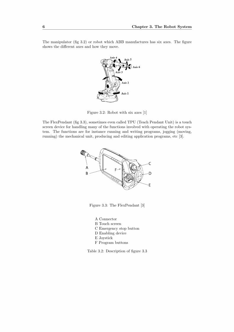
The manipulator (fig 3.2) or robot which ABB manufactures has six axes. The figureshows the different axes and how they move.
Figure 3.2: Robot with six axes [1]
The FlexPendant (fig 3.3), sometimes even called TPU (Teach Pendant Unit) is a touchscreen device for handling many of the functions involved with operating the robot sys-tem. The functions are for instance running and writing programs, jogging (moving,running) the mechanical unit, producing and editing application programs, etc [3].
Figure 3.3: The FlexPendant [3]
A ConnectorB Touch screenC Emergency stop buttonD Enabling deviceE JoystickF Program buttons
Table 3.2: Description of figure 3.3

3.1. Coordinate System 7
Keywords [4]:
– Manipulator A Manipulator is a generic term for mechanical units that are usedto move objects, tools, etc. The term also includes robots as well as positioners.
– Robot A robot is a mechanical unit with a tool center point (TCP). The termrobot does not include the controller.
– Positioner The positioner is a mechanical unit used to move a work object. It canhave one or more axes, normally no more than three axes. A positioner normallydoes not have a TCP.
– Robot cell A robot cell comprises all parts needed for production.
– Mecanical unit A Mechanical unit can be jogged, it can be a robot, a singleadditional axis or a set of external axes.
3.1 Coordinate System
All Cartesian coordinates in a robot program are stored in rectangular coordinates, xyz,values for positioning. These values are related to a coordinate system; the coordinatesystems can in turn be a part of another coordinate system and so on [1]. Some coordi-nate systems are predefined in the robot and are not available for the user to alter, butsome coordinate systems are visible and can be programmed by the user.
For the robot to be accurate and precise, calibration is very important. If the robot orany external axes is not calibrated correctly the outcome would be bad positioning inone of the coordinate systems and this will have a negative affect in the agility of therobot [1].
Some of the most important coordinate systems to understand for this thesis are thebase-, world-, tool-, user-, and object frame.
3.1.1 Base frame coordinate system
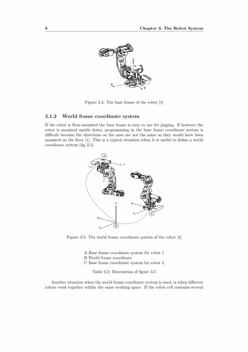
The base frame coordinate system (fig 3.4) has its zero point in the base of the robot.This makes movements predictable for fixed mounted robots; with the base frame onecan jog a robot from one position to another [4]. The base frame coordinate system isused when defining and calibrating a tool or a work object. When no coordinate systemis defined, the robot’s positions are defined in the base frame.
8 Chapter 3. The Robot System
Figure 3.4: The base frame of the robot [4]
3.1.2 World frame coordinate system
If the robot is floor-mounted the base frame is easy to use for jogging. If however therobot is mounted upside down, programming in the base frame coordinate system isdifficult because the directions on the axes are not the same as they would have beenmounted on the floor [1]. This is a typical situation when it is useful to define a worldcoordinate system (fig 3.5).
Figure 3.5: The world frame coordinate system of the robot [4]
A Base frame coordinate system for robot 1B World frame coordinateC Base frame coordinate system for robot 2
Table 3.3: Description of figure 3.5
Another situation when the world frame coordinate system is used, is when differentrobots work together within the same working space. If the robot cell contains several

3.1. Coordinate System 9
robots that need to communicate with each other, then the same world frame coordinatesystem is usually defined for all robots.
3.1.3 Tool frame coordinate system
A tool is an object on a robot used to for instance arc welding, welding, etc. The toolcan be mounted directly or indirectly on the robots axis six (the turning disk, fig 3.6)or it can be fitted in a fixed position within the robots working range. All robots have apredefined tool frame coordinate system called tool0, located at the center of the platteron axis six of the robot.
Figure 3.6: Center of the platter of axis six on the robot [4]
All tools must be defined with a tool center point (TCP) (fig 3.7), the TCP is the pointthat reaches the programmed point or is the point which moves when jogging the robot.The robot can have a number of TCPs but only one can be active at the time.
Figure 3.7: The tool frame coordinate system of the robot [4]
If a tool is replaced, teared, weared, or changed; the tool frame has to be redefined, butthe program does normally not have to be altered [1].

10 Chapter 3. The Robot System
There are two types of TCPs, movable and stationary TCP.
– The majority of all applications deal with moving TCPs, moving TCPs moves inspace along with the manipulator. A typical moving TCP would for instance bethe tip of an arc welding gun (fig 3.7).
– When stationary TCP is used the manipulator moves and the TCP is stationary,in those applications the TCP is defined in relation to the stationary equipmentand not the moving manipulator.
3.1.4 Work object coordinate system
A work object (3.8) is a coordinate system that is defined by the user and is mainly usedto simplify programming and editing programs due to program displacement. All pro-grammed positions in a work object are related to that work object coordinate system.The work object must be defined in only the user frame (related to the world frame) orboth the user- and the object frame (related to the user frame) [4].
Figure 3.8: The user- and object coordinate system [1]
A robot can have several work objects, either for having different work pieces or thesame work piece but on different locations.
Suppose that a robot is working on a table (fixture), suppose further that the tablehas to be moved for some reason. If the robot program is not built up by work objects,then the whole program is useless, because all the robot targets are in a relation to thebase frame of the robot. Hence if the fixture moves then the points in space are notin the same relation as they were before the fixture moved. On the other hand if therobot program was built up by work objects, then the programmed robot points are inrelation to the work object which in turn is in a relation to the base frame. Since thework object is definable by the user the only thing that needs to be done is to redefinethe work object and the relation between the work object and the base frame will auto-matically be updated. Given that the work object is redefined the programmed pointsare also moved, the robot can now continue the same work on the fixture as before eventhough the fixture has been moved.

3.1. Coordinate System 11
This technique is well suited for offline programming, since work objects first can bedefined in a virtual world and then updated rather easily in the physical world; this isoften the case because the virtual world rarely coincides exactly with the physical world.
This figure (fig 3.9) summarises the different coordinate systems and the relation be-tween them.
Figure 3.9: Different frames of the robot and their relation [4]
A User frame coordinate systemB World frame coordinate systemC Base frame coordinate systemD Moved user coordinate systemE Work object coordinate system, moved with user frame coordinate system
Table 3.4: Description of figure 3.9

12 Chapter 3. The Robot System
3.1.5 Defining TCP
Since all the positions of a robot in the Cartesian coordinate system are always relatedto its tool center point (TCP) [2], an accurate TCP calibration is crucial. A tool coor-dinate system can either be defined manually or the robot can be used as a measuringtool. Manual definitions can be used if accurate data for the dimensions of the tool areavailable.
To define a tool using the robot as a measuring tool, a world fixed tip is needed withinthe robots working range. The robot must then be jogged to at least four differentlocations as close as possible to the world fixed tip. These positions are called approachpoints (fig 3.10) [1].
Figure 3.10: Defining a tool center point of the robot [1]
To define a more accurate tool one has to use more points than four, to specifythe tools orientation, elongator points are used. The elongator points are defined bypointing out the z axis and the x axis of the world fixed tip.
3.1.6 Defining work objects
A work object is defined by touching three points (fig 3.11) in space using the robot asa measuring tool, two x points and one y point. The lines x and y are then fitted to beperpendicular to each other.
Figure 3.11: Defining work objects with the robot as a measuring tool
Chapter 4
Intelligent Interface Agents
This chapter presents the in-depth study of the thesis; it focuses on intelligent interfaceagents. What agents can do for the user and the challenges with them are discussed. Dif-ferences between wizards and guides are mentioned, direct manipulation and autonomousagents are discussed.
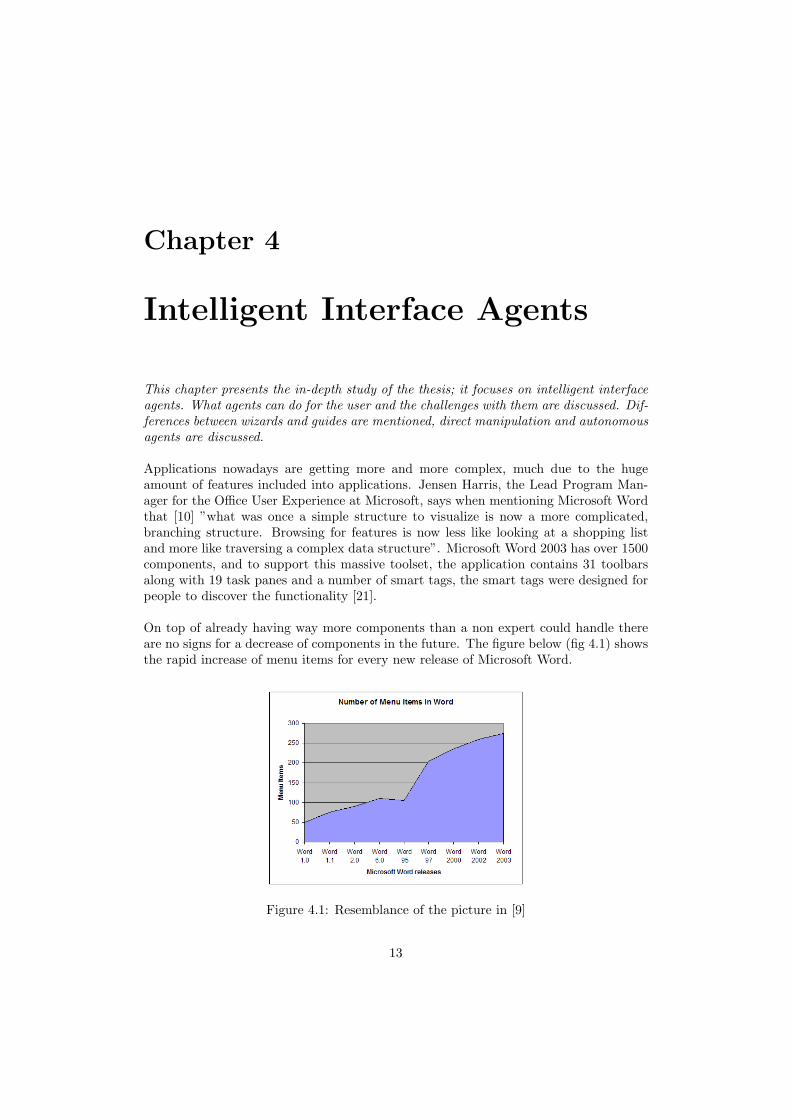
Applications nowadays are getting more and more complex, much due to the hugeamount of features included into applications. Jensen Harris, the Lead Program Man-ager for the Office User Experience at Microsoft, says when mentioning Microsoft Wordthat [10] ”what was once a simple structure to visualize is now a more complicated,branching structure. Browsing for features is now less like looking at a shopping listand more like traversing a complex data structure”. Microsoft Word 2003 has over 1500components, and to support this massive toolset, the application contains 31 toolbarsalong with 19 task panes and a number of smart tags, the smart tags were designed forpeople to discover the functionality [21].
On top of already having way more components than a non expert could handle thereare no signs for a decrease of components in the future. The figure below (fig 4.1) showsthe rapid increase of menu items for every new release of Microsoft Word.
Figure 4.1: Resemblance of the picture in [9]
13
14 Chapter 4. Intelligent Interface Agents
Applications like Microsoft Word are bloated, and the question is how do we solve thecomplexity problem that exists? How do we help end users use features and methods inan application, but more importantly how do help end users understand the features andhow do we help them to perform them. Even the graphical user interfaces (GUI) adds tothe learning complexity for inexperienced users [22], which leads to unnecessary failures.These problems are highly noticeable even in the ABB robotics world, the application inthe FlexPendant offers great methods but they are sometimes hard to grasp and perform.
Intelligent interface agents are a way of alleviating these problems. Imagine havinga teacher that could tutor you any time of the day, who was always there to guide andinform you. Or imagine that you have a supervisor that you could ask any question,dumb or smart any time and day of the week. Image now that the tutor or supervisoris not human, but rather a computer program called intelligent agent.
Intelligent interface agents could guide and inform users so that they could solve aproblem. Agents could teach users the interface by guiding them step by step throughthe entire process and could also prevent users from making mistakes [7]. Intelligentagents are computer programs that simulate a human relationship by doing somethingthat a another person could do for you [18].
4.1 History of Agents
Artificial intelligence and agents have been in a close relationship over the last thirtyyears [17]. AI discusses the ability for a system to learn and plan, while agents tryto integrate those components into an entity. However even though AI and agentsare tightly coupled, intelligence plays a rather small roll in an agent or as Etzioni [8]puts it ”Intelligent agents are ninety-nine percent computer science and one percent AI”.
In the 1990’s, drawing from the traditional research within artificial intelligence andhuman computer interaction a new paradigm was born, the software agent [15]. Kay[12] argues that the interface agent has the ability to revolutionize computing scienceas we know it today, the agent(s) will allow user’s to go from direct manipulation tointeractions. Agents will act as experts so users doesn’t always need to have the spe-cific ”know how” for accomplishing certain tasks. Regular people could now accomplishthings that before required experts.
4.2 What is an Intelligent Interface Agent?
Intelligent agents are independent computer programs operating within software envi-ronments such as operating systems, databases, or computer networks [16]. MichaelWinikoff and his colleagues [23] define an intelligent agent as one which is able to makerational decisions, i.e., blending proactiveness and reactiveness, showing rational com-mitment to decisions made, and exhibiting flexibility in the face of an uncertain andchanging environment.
The word agent is often used to describe people who assist or help others to achieve acertain goal. Agents could for instance be travel agents, personal assistants, secretaries,etc. The work an agent does is to assist someone in the best possible way, it could be

4.3. What can agents do for the user? 15
to provide help, advice or ”run errands” for the user [11].
For the relationship between the agent and the user to work, the interaction betweenthem must be flawless. This is also the case with virtual computer agents; if the inter-action between the computer agent and the user is good the advice or help from theagent will most likely be of great interest for the user.
4.2.1 Intelligence
The word ”intelligence” is often associated with human intelligence; that kind of in-telligence that doesn’t exist in today’s computer technology. But the word intelligencecould also mean expertise, knowledge and how to accomplish certain tasks; this is thekind of intelligence that this paper refers to and focuses on.
4.2.2 Interface
For an agent to be considered an ”interface agent”, the agent is required to communicatethrough input and output of the user interface. An agent can observe actions taken bythe user on the interface and act according to the findings. The agent should also beable to manipulate the interface such as adding graphics or animation to it [11].
4.2.3 Agent
Defining the word agent is not easy; almost every researcher in the human computerinteraction field have their own definition. Lieberman [13] defines agent as ”an agentis any program that can be considered by the user to be acting as an assistant orhelper, rather than as a tool in the manner of a conventional direct-manipulation tool”.Maes [14] describes agents as ”Instead of user-initiated interaction via commands and/ordirect manipulation, the user is engaged in a co-operative process in which human andcomputer agents both initiate communication, monitor events and perform tasks. Themetaphor used is that of a personal assistant who is collaborating with the user in thesame work environment.”
4.3 What can agents do for the user?
Information, tools and functions on different applications is growing and will most likelycontinue on that path; this is not sustainable because the information load burdened onthe user is too much. At the same time, users not trained for interactions with comput-ers are increasing [14].
The most dominate interaction between users and computers now is direct manipu-lation which Schneiderman [19] describes as, the user is required to initial all tasks andmonitor all events. This interaction needs to change if untrained users are supposed toperform effectively and efficiently on an application.
For having non professional users perform well on computers, help is needed, help thatthey could get any time of the day and for as long as they need. Help that never getstired of helping and help that returns feedback in electronic speed. This help could be
16 Chapter 4. Intelligent Interface Agents
from a software agent; this agent would be the electronic advisor and assistant. Maes[14] discusses four main things that an agent can do for the user:
– Performing tasks on the user’s behalf
– Training and teaching users
– Help out with different user collaboration
– Monitor events and procedures
4.4 Challenges with Interface Agents
According to Middleton [15] there are three issues that must be addressed before a usercan successfully collaborate or interact with an agent, and they are:
– Knowing the user
– Interacting with the user
– Competence in helping the user
4.4.1 Knowing the User
The first issue, knowing the user, involves user preferences and habits. For instance ifa travel agent was to book a trip for a customer, then it would be highly relevant if theagent knows that the customer often uses rental cars, cheap or expensive hotels, and ifthe customer travelled business or economy class. If a secretary often interrupted withirrelevant information it would be annoying for the manager.
At any given time the interface agent must at least have an idea of what the useris trying to do in order to give effective assistance, without being annoying. Anotherproblem can occur when users deal with multiple tasks, the agent must know now whenthe user stops with one task, and starts with another [15].
4.4.2 Interaction with the User
From the field of direct manipulation it is known that users want to feel in control ofwhat their application or agent is doing, the questions are how do agents build userstrust and when that trust is established how much control do the agents get? [15]
4.4.3 Competence in helping the user
Once the agent knows what the user is trying to accomplish and has a good interactionstyle, the agent must formulate a plan of action to help the user [15]. The plan is to:
– Know when and if to interrupt the user
– Perform tasks autonomously
– Finding strategies for partial automation of tasks

4.5. Wizards and guides 17
Middleton [15] says that there is currently very little research about how user’s bestcan be helped. He argues that real user trials are needed to demonstrate and evaluateeffectiveness and usefulness performed by agents. If an agent doesn’t reduce the user’sworkload in a real working environment, they then do more evil than good.
4.5 Wizards and guides
Two different kinds of user interface (UI) agents are wizards and guides. The most com-mon UI agent is the wizard [5]. Wizards provide assistance to a problem by breakingdown the task into subtasks; these agents do typically redesign the original GUI so thateach subtask is presented to the user one at a time so that only one value could bealtered. Wizards do in general not use any artificial intelligence [7].
Guides work completely different than wizards; guides provide assistance through firstobserving the interaction between the user and the system and then according to thefindings the guide presents information. A guide often lies ”on top” of the original GUI,and somehow communicates how to perform the next step in a task and draw’s a per-son’s attention to where the next step will occur [7].
There are some major differences between guides and wizards but when is one of thembetter then the other?
Because wizards break down a task into subtasks they are best suited when the prob-lems are linear and can be algorithmically solved. Since wizards also alter the originalGUI the user don’t learn that much, wizards are at their best when users do not usea particular method often or care about how to perform it. When tasks are performedvery infrequent it is less important that users get informed of them, however if it is veryimportant that the task is performed successfully, wizards are best to use.
Guides on the other hand assists the user without altering the GUI, this means thatopportunities to make mistakes are more than with wizards. On the other hand sinceguides lie on top of the original GUI the user learns more. When tasks need to beperformed quite often and/or it is necessary that users needs to get educated on them,guides are often the choice to implement.
4.6 Autonomous Agents
Another type of agent besides wizards and guides are autonomous agents, these agentstake actions without users having to intervene. Traditional interface design focusing onuser agent interaction is often designed so that the user and agent take turns in acting.The agent displays results depending on the users input and waits for the next input.However the agent does nothing between inputs from the user and the user does nothingin the interface while the agent is running, every action done by the agent is initiatedby the user [13].
Autonomous agents on the other hand take a slightly different approach, here the idealies in that the agent may need to interact with the interface simultaneously as theuser [13]. Autonomy means always running and self-controlled, autonomous agents are

18 Chapter 4. Intelligent Interface Agents
precisely that, they operate in parallel with the user and when the agent discovers asituation that needs to be viewed by the users, it shows the information to the client.Assistants that need constant supervision and specific instructions are not very helpfulor timesaving; on the other hand if assistants based on previous knowledge or dele-gations were allowed to act independently they would be of tremendous help. Someautonomous agent’s operate outside the user interface, for instance there are programsthat send e-mail to clients to notify them that a webpage, which is of great interest tothat specific user, has been updated [13].
For an agent to be considered both interface agent and autonomous, there must besome part of the interface that the agent operates by itself. The user must also beable to see autonomous actions taken by the agent and the agent must be able to seeautonomous actions taken by the user in the interface [13].
Lieberman [13] says that autonomous interface agents work best in situations wheretheir decisions are not critical. Because people are afraid of letting go of the controlwhich could lead to bad decisions made by the agent without the users consent, thisfear is justified. There are however many scenarios where the absolute best choice isnot needed for the agent to be useful, sometimes the ”good enough guess” is highlyappreciated.
4.7 Direct Manipulation versus Interface Agents
Direct manipulation was coined by Ben Shneiderman in 1982 to describe those days’ suc-cessful systems. Shneiderman [20] explains the direct manipulation goal as ”to createenvironments where users comprehend the display, where they feel in control, where thesystem is predictable, and where they are willing to take responsibility for their actions”.
The aim with direct manipulation is to let users directly manipulate objects presentedto them. To help users learn and use the interface, intuitiveness such as having real-world metaphors for actions would help. An instant feedback would help users to reducetheir error because with direct manipulation the users see the results of their actionsbefore completing the procedure. A great example of direct manipulation is for instanceWindows paint program, to resize a graphical object, such as a rectangle, the user hasto touch on one of the edges and drag it with the mouse. While the user holds downthe mouse button and drags the object the interface shows the user how the object isbeing reshaped.
Even if some researches argue that direct manipulation is more intuitive and natural,and Ben Shneiderman arguing that direct manipulation is the only way to go, PattieMaes [20] does not see eye to eye with them. She says that users need software agentsbecause ”our current computer environment is getting more and more complex, and theusers are becoming more and more naive, the number of tasks to take care of, and thenumber of issues to keep track of, are continuously increasing”. In Shneiderman andMaes debate in intelligent User Interface conference [20] she said:
”As we know from other domains, whenever workload or information load gets toohigh, there is a point where a person has to delegate. There is no other solution than todelegate. For example, many of you may have students that you delegate certain tasks
4.8. Final comments 19
to, or you may have personal assistants that you delegate certain tasks to, not becauseyou can’t deal with those tasks yourself, but because you are overloaded with work andinformation. I think the same will happen with our computer environments: that theybecome just so complex and we use them for so many different things that we need to beable to delegate. We need to be able to delegate to what could be thought of as ”extraeyes or extra ears” that are on the lookout for things that you may be interested in. Wealso need ”extra hands or extra brains,” so to speak, because there will be tasks thatwe just cannot deal with because of our limited attention span or limited time, and weneed other entities to be able to represent us and act on our behalf. ”
4.8 Final comments
As mentioned in the beginning of this chapter, the number of components is rapidlyincreasing in applications. Finding, performing and understanding them is not easy forbeginners and sometimes not even for experts. Humans need assistance, delegating cer-tain tasks or certain parts of tasks to agents or at least letting them make suggestions tous would undoubtedly reduce our own work- and memory load. Feedback is also neededfor our actions, did we do good or could we do better, an important consideration forthe agent however is to not provide too many insights and thereby annoy the student [6].
Even if we let agents act on our behalf we still need to feel in control over them, we needto bypass them if we want to and we need to understand what they are doing [20]. Thisis especially vital in the robotics world, if bad decisions are made without the humanconsent there could be both time and financial losses.
There is however some issues left to discuss for the future, for instance; should therebe more than one agent? Should agents use personification such as facial expressions?What is the best metaphor for an agent? Should a user be responsible for actions madeby their agent?
Nevertheless just like with human communication, the nature of the relationship be-tween two intelligent agents, human and machine, is paramount to success.

20 Chapter 4. Intelligent Interface Agents

Chapter 5
Mock-up
This chapter presents the first mock-up made. It explains the technical parts of theimplementation, such as which code version that were used. It compares the original in-terface against the mock-up, and it presents two new features, a guide and a text viewer.
One of the problems discovered in the beginning of the project was that work objectswere not easy to perform or understand. Manuals explaining the different techniqueswhere not written for first time users and the structure involving calibration were notintuitive.
Since problems were discovered before the field studies a mock-up was generated topresent solutions to some of the basic problems. The mock-up was also to be used assomething for the ”experts” on the field to remark on, and to compare the originalgraphical user interface (GUI) against.
The mock-up restructured the calibration offers so that they would seem more intu-itive for the user and it also included an intelligent software agent (guide) that in asimple way guided the user through a tool center point calibration. The guide consistedof a textbox that gave information and recommendations to the user while calibrating atool center point. The guide also drew the user’s attention to where the next step wouldoccur by marking it on the GUI.
5.1 The Implementation
Applications needed for implementing the mock-up were, RobotStudioOnline 5.08.0144,Robot Application Builder 5.08.0144, RobotWare 5.08.0144, and Virtual Controller TestApplication 5.08.0144.
The code was built in ABB code version 5.08.0144. The code language was C#, andthe editor used was Visual Studio 2005 Professional Edition. The mock-up was con-tinuously tested on Virtual Control Test Application, which is the virtual substitute toa real robot controller. To test on a real controller the code has to be downloaded tothe robots controller. To download the code to the controller, the computers networkconnection has to be connected to the controller’s service port.
21
22 Chapter 5. Mock-up
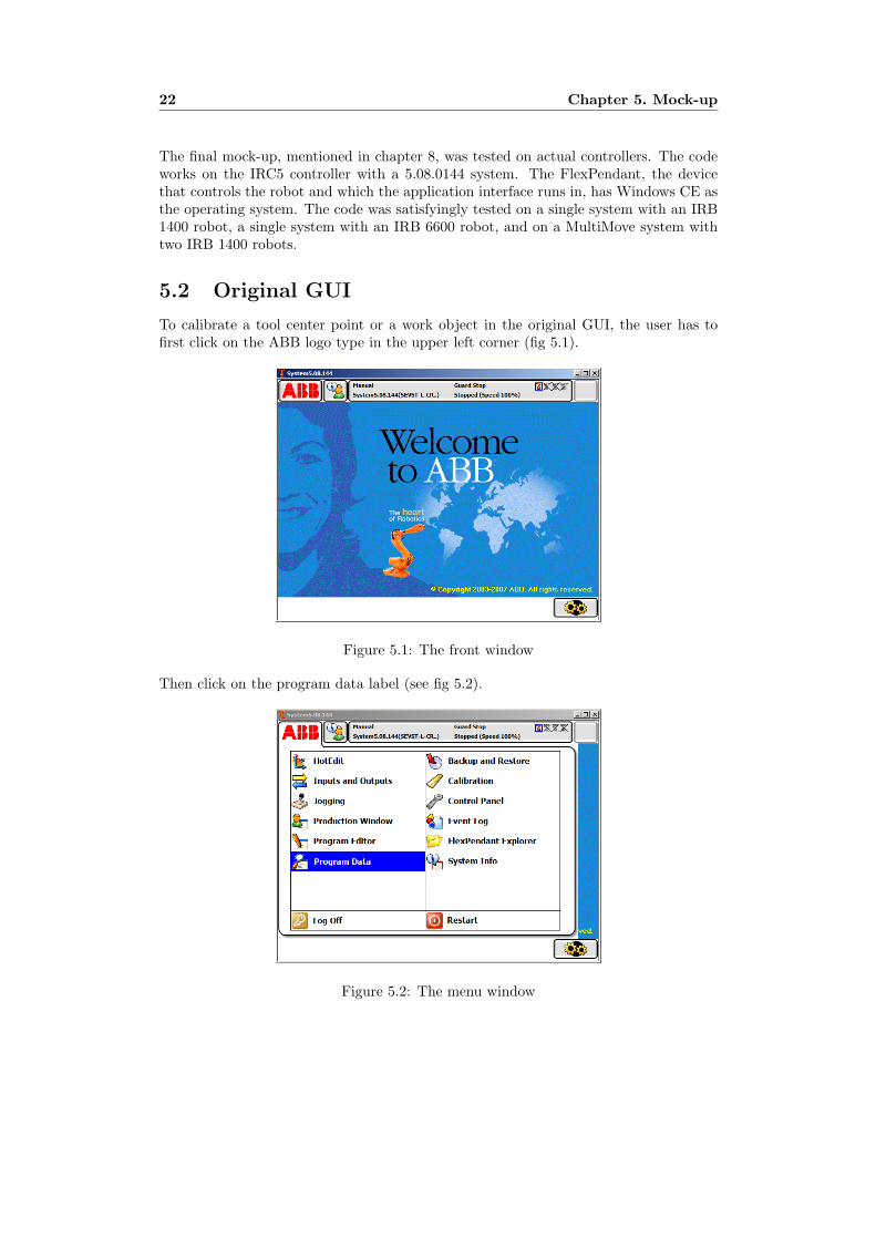
The final mock-up, mentioned in chapter 8, was tested on actual controllers. The codeworks on the IRC5 controller with a 5.08.0144 system. The FlexPendant, the devicethat controls the robot and which the application interface runs in, has Windows CE asthe operating system. The code was satisfyingly tested on a single system with an IRB1400 robot, a single system with an IRB 6600 robot, and on a MultiMove system withtwo IRB 1400 robots.
5.2 Original GUI
To calibrate a tool center point or a work object in the original GUI, the user has tofirst click on the ABB logo type in the upper left corner (fig 5.1).
Figure 5.1: The front window
Then click on the program data label (see fig 5.2).
Figure 5.2: The menu window

5.2. Original GUI 23
Followed by choosing tooldata in the data types list (fig 5.3).
Figure 5.3: The data type list window
The window for calibrating a tool center point is shown in figure 5.4.
Figure 5.4: The TCP calibration window

24 Chapter 5. Mock-up
5.3 Restructuring
Since both of the methods tool center point and work object are called calibrationtechniques and since there is a menu called calibration it would be more intuitive to putthe two methods there (fig 5.5).
Figure 5.5: The menu window
When the user has clicked on the calibration label then he or she has to choose whichrobot to calibrate (fig 5.6).
Figure 5.6: Select the mechanical unit window

5.3. Restructuring 25
In the calibration window there are three different techniques to choose from (fig 5.7),the tool center point-, the work object-, and the mechanical unit calibration.
Figure 5.7: The calibration window
If the tool center point button is clicked, three options are presented (fig 5.8).
Figure 5.8: The calibration window when TCP button is clicked
The first option is a text viewer, which is explained more in detail in the next section,the second option is the guide mode where a guide helps the user perform a tool centerpoint calibration (TCP) and the last option is for the ”experts” whom without helpwants to perform a TCP calibration.

26 Chapter 5. Mock-up
5.4 Viewing text on the FlexPendant
One of the features added in the mock-up was text viewing (fig 5.9). The text viewer’spurpose is to inform the user about the different methods how they are used, how toperform them and why the user needs to perform them.
Figure 5.9: The text viewer window
5.5 The Guide
The other feature implemented in the mock-up was the guide (fig 5.10).
Figure 5.10: The Guide in the development stage
The guide is basically built up with a textbox that has information and recommendationsfor the user to view depending on what they are doing. The first step in the guide modeis to decide if a new tool has to be created and then calibrated or if an old tool has tobe recalibrated (fig 5.11). Besides giving information to the user the guide draws theuser’s attention to where the next step will occur (fig 5.11 and 5.12).
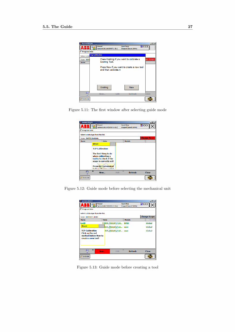
5.5. The Guide 27
Figure 5.11: The first window after selecting guide mode
Figure 5.12: Guide mode before selecting the mechanical unit
Figure 5.13: Guide mode before creating a tool

28 Chapter 5. Mock-up
Chapter 6
Field Studies
This chapter summarises the field studies, the problems users deal with on the field ismentioned as well as what users and experts thought about the mock-up.
The field studies took place in Fort Collins, Colorado, USA and Auburn Hills, Michi-gan, USA. The company visited in Fort Collins was Wolf Robotics; they build robotcells and do robot installations using ABB robots. The company visited in Auburn Hillswas ABB; they do a lot of installations for welding customers, they also have trainingfacilities where employees from different companies go to for robot learning and train-ing. The people interviewed in the States were those that deal with the FlexPendant ona daily basis, they were installation technicians, customer support, software engineers,and so on.
All the employees interviewed were asked a couple of questions, they saw the mock-up and then the robot calibration topic was discussed.
6.1 The Mock-up
All of the employees that got interviewed really liked the intelligent agent, one of theemployees in Auburn Hills who was a former installation technician but now a softwareengineer said ”this is exactly what I wished for, an intelligent agent that step by steptells me how and especially why I need to perform certain tasks, this guide is really go-ing to be helpful for all the customers that don’t exactly know how to calibrate a robot.”
This is a summary of what the interviewed employee’s thought about the mock-up:
– The textbox is a great idea, because the users now have their own teacher withthem all the time. With the textbox the end users know how to do certain tasksbut most importantly they can read and understand why they need to do them.
– It’s good that the ”guide mode” has default values so that the end users knowwhat the default values (the recommended values) are when calibrating a robot.
– The idea that the ”guide mode” has the same background as the original graphicaluser interface (GUI) was appreciated; because it leads to end users, after sometime, knowing how to perform a method.
29
30 Chapter 6. Field Studies
– The terminology in the guide must be formal and easy to understand. One of theemployees at Wolf Robotics said ”text should be in a formal language, nobodycares about the math or the technique behind the method, what the customers docare about is what the technique can do for them, the guide should present somepros and cons with every choice”.
– Another employee at the same firm said that ”it would be better that the guidepresents text that compares the default option to the selected one instead of justexplaining what the selected value is, this would lead to better knowledge for thecustomer”.
– Having the PDF manuals directly on the FlexPendant to view instead of on apaper is much better because bringing along manuals is tedious. Having manualsin electronic form means that users could search through text automatically whichis a huge time saver. The other good thing is that when explaining text is rightin front of the users there is a more likelihood of users actually trying to performand learn different techniques.
6.2 Calibration problems
This is a summary of different calibration problems end users have on the field, and alsothings that needs to be done within calibration to make the techniques more usable andensure a higher quality:
– The biggest reason why end users don’t use work objects is because they don’tknow why they need work objects and what the object can do for them.
– When a tool center point (TCP) is calibrated people often don’t know what anelongator point is, they also don’t know why and when they should use more thanfour points to calibrate a TCP.
– When calibrating TCP, it would be time saving to know which of the points thatis most far off, which point that causes the biggest discrepancy.
– The feedback in the application that shows how good precision the tool has aftera TCP calibration is done is very poor.
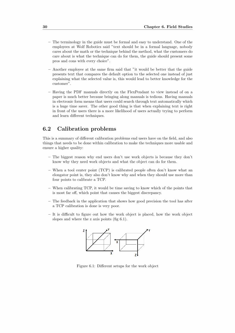
– It is difficult to figure out how the work object is placed, how the work objectslopes and where the z axis points (fig 6.1).
Figure 6.1: Different setups for the work object

6.2. Calibration problems 31
– The work object points should be saved; the benefits are explained in the analysischapter.
– When a robot program is created offline the installation technician needs to gothrough every point when installing to test if the program actually runs correctly.Since the installation technician doesn’t have knowledge about the program he orshe doesn’t know where the next point is placed in space. This becomes a majorproblem and could easily lead to robot crashes, tool crashes or damage to thefixture.
– There are benefits for saving TCP calibration points and they are explained in theanalysis chapter.
– It is difficult to know where all the markings are on a specific robot model whentrying to do a revolutions counter update.
– The FlexPendant uses the metric system which is hard to grasp for people thatdon’t use mm in a daily basis, for instance Americans are more familiar to inches.

32 Chapter 6. Field Studies
Chapter 7
Analysis
This chapter analyses the problems mentioned in the previous chapter. Real life exam-ples explaining the problem are presented as well as solutions to each and every problem.
7.1 How do we help robot users understand differentcalibration techniques?
The text viewer implemented in the mock-up is something that would help to lessenthe knowledge gap for the users. The users could easily read about different calibrationmethods, features like search, zoom, etc would also be of great help.
Another thing appreciated with the mock-up which would assist people when perform-ing calibration on a robot is the guide. The guide acts like a tutor and assists the userstep by step through the calibration process and explains why and how one should doa work object or a TCP calibration. The guide also gives instant feedback and recom-mendations.
For users that do not program offline, that is to say do a robot program on the flex-pendant and not with RobotStudio, there could be some sort of warning (a pop-up) tonotify users that program without work objects may not be a good idea.
7.2 Why aren’t users defining work objects?
The biggest problem with work objects is the user’s lack of knowledge, knowledge aboutwhat a work object is, what it can do, how to perform and place them, and when to usethem.
The reasons are many for not knowing or learning about a work object. The majorreason is time constraints. The people whose job it is to set up and program a robotcell are pressured both by management and deadlines to make the cell work as soonas possible. Because of the heavy work load and the fact that it takes longer time inthe beginning to set up a robot cell with work objects than without, they often don’t
33

34 Chapter 7. Analysis
include the technique into their robot program.
Other reasons for not having work objects are that sometimes the robot has a bigtool mounted on it which makes is difficult to perform the calibration, and sometimesthe tool may lack a pointing device which is necessary for defining work objects. If therobot lacks a pointing device the installation technician has to unmount the existingtool, mount on a pointing device, perform the tool center point calibration, define thework objects, unmount the pointing device and remount the original tool. Even thoughwork objects might take longer time in the beginning the technique is very powerful andtime saving in the end, because of its ability to move whole programs to any location inspace with just redefining the work object.
7.3 Why work objects points should be saved
Now and then when work objects are placed on fixtures users mark the positions of thepoints on the actual fixture where the work object is placed. This is because if customersmonths or years from now want to go back and recalibrate the work object they haveto know where it was originally put. The markings are for instance done with markerpens, which is not a good idea because the marks tend to vanish as time goes by. If thework object points were saved the users would never have to mark the fixture to findout where the points are positioned, the robot could show it to them.
When robot programs is programmed offline in RobotStudio, the installer needs totest run the program on site to see if the robot is performing its work correctly. Sincethe virtual world often doesn’t coincide exactly with the real world the installation tech-nician often has to modify the work object points, which is very tedious, and takes a lotof time. If the work object points were saved then the technician could for instance pressa button on the FlexPendant and the robot could move to the defined point instead ofthe technician jogging the robot to the point.
When customers want to double the productivity, the robot cell is often copied andsetup on a different location. When a robot cell is copied the new and the old one rarelycoincide exactly. Hence saved work object points would be of great interest even in thisexample.
Two more scenarios where saved work object points come to use is when, the robotcell is built on one place and then shipped to another location, or if somehow the fixturethat the robot is working on has moved.
7.4 Why the work object should be picture illustrated
One of the problems with work objects is that it is hard to figure out how they slope andlie on a fixture, this problem often becomes evident when customers have to recalibrateold work objects on a fixture.
Let’s assume a robot is programmed without RobotStudio, let’s also assume that therobot or tool crashes, or that the fixture somehow moves, two years after the initialsetup. Since someone needs to recalibrate the robot and its work objects they need to

7.5. Why the TCP points and calibration movements should to be saved 35
find out where the work object was originally put, where the z axis pointed and if therewere any particular reasons why the work object was placed in that specific way. This in-formation, is for the operator no where to be found in the FlexPendant, which becomes ahuge problem on the field and often the whole robot cell needs to be rebuilt from scratch.
Pictures of the work object and text explaining it would really be helpful if they wereto be viewed on the FlexPendant. The picture could be taken from the actual fixtureand be downloaded to the controller, the text could be typed in on the FlexPendant.
7.5 Why the TCP points and calibration movementsshould to be saved
Tools can crash, or they can wear down so that the tool center point (TCP) has to berecalibrated quite often. The procedure takes time and the result is highly dependentof how good the person doing the calibration is on jogging the robot and how good hisor hers eyes and patience are.
Let’s say that the TCP is bent or broken somehow and that there exists a similartool that could replace the broken one. Because the replacement tool is not going tohave the exact same geometry as the original tool a calibration of the new tool has tobe done to make sure that the TCP is accurate. If the TCP points and movements fromthe original calibration were saved, the installer could press some button and the robotcould automatically orient to each point and then the installer, if the point is off, couldmodify the position instead of jogging the robot to each and every position. This wouldbe a huge time saver but would also lead to a more accurate calibration of the TCP.
Another benefit of saving the TCP points is that the system could compare the oldtool against the new one. The user could get information about how accurate the newtool is compared to the old one; the user could also get information about which of thepoints in the new tool that causes the biggest discrepancy compared to the old tool.
7.6 Problems encountered on installation
As mentioned before if the robot program is pre created in RobotStudio all the robottargets and work object points must be test run and if needed modified ”on site” to in-sure correct robot positioning. When the installation technician test runs the programthey repeatedly press a button on the FlexPendant which makes the robot step throughevery robot target in the program. Once the robot reaches the target and if that targetis off it can be modified. This actually causes big problems for the technician; sincethe installer does not know where the next robot target is positioned on the fixture,pressing the button on the FlexPendant, could make the robot run into the fixture orinto a nearby object and thereby crash the tool, or the fixture.
There are some ideas that could make the setup of a robot cell safer. One thing thatcould be done is to have some sort of a ”pre modify position” where the robot stopsbefore reaching the target point. When the robot stops in its ”pre modify position”point the technician could go to the robot and ensure that no obstacles are in the way.
36 Chapter 7. Analysis
Something that might work better is to have pictures of every point the robot is goingto, this way the technician would know where the robot is heading and could take pre-cautions according to the information. Even though this approach would be helpful forthe technician it would mean that pictures on every point on the fixture must be taken.It is however not reasonable to assume that the programmer is going to copy and pasteevery point from RobotStudio, which would take a lot of time and would be very tedious.
Another solution that could solve this problem without burdening the programmerwould be, when the installation technician presses the button for making the robotgo to the next robot target there could be some counter that counts down to the targetin mm or cm. The distance could be shown in x, y and z. This information would bemore than enough and it would be especially important when robot targets are near afixture so that the operator knows how near the fixture the robot is actually going.
7.7 Why pictures are necessary on revolution coun-ters update
Robots in a plant are neither clean nor completely unscratched. This makes the updat-ing of the revolution counters a little bit of a hassle, therefore having pictures of themarkings of every axis so that the users know where to look for would be recommended.
After the revolution counters are updated, the robot should go to its sync position,so that the technician can see if something is wrong with the robot. There should alsobe some sort of a popup that tells the technician to actually go too the robot and checkits sync position. In real workplaces there are often fences around the robot and tech-nicians frequently program and calibrate the robot from outside the fence, which in theend not gives a good accuracy.
7.8 Miscellaneous problems and thoughts about cal-ibration
Suppose that a robot program is created offline and that an installation technician ison a plant to install the robot cell. Also suppose that when the technician test runsthe program he finds out that the first couple of points are misplaced about two mm tothe left. This would basically mean that if the first couple of points are misplaced tothe left then we could assume that the rest of the points in the program are also goingto be misplaced two mm to the left. In this case there should be some sort of best fitapplication that automatically could reposition all the next coming points so that thetechnician doesn’t have to modify all the positions manually.
Suppose that axis six was badly calibrated and suppose further that a user defines awork object while turning axis six. The work object would get an offset unknown to theuser. Suppose instead that the user didn’t turn axis six when defining the work object,now the work object would still get an offset but the offset would be the same for everypoint. It is better to have the same offset on every point than to have different offsets onevery point. It is recommended to use as few axes as possible when defining work objects.

7.8. Miscellaneous problems and thoughts about calibration 37
There is a need for warnings/notifications when renewing tool center points or workobjects, when users recalibrate an old tool there should be some sort of pop up thatmentions which modules and/or routines that will be affected by the change. If a user-frame is modified then it should mention which objectframes that will be affected andso on. This also helps out with the learning process for the users; by warning users theyunderstand the relations between the different coordinate systems.

38 Chapter 7. Analysis

Chapter 8
Results
This chapter presents the results of the thesis. With data collected from the field studies,the first implemented mock-up could be improved, this chapter discusses and explains theimprovements.
As mentioned earlier, problems within the area of robot calibration exists, and oneof the biggest being the lack of knowledge in the users about how and why certain pro-cedures should be done. To reduce the gap, restructuring the calibration bits of theapplication has been done to ensure more intuitiveness. Features such as text viewingon the Flexpendant are added to the mock-up. Most importantly, a guide has beenimplemented to assist and inform end users throughout the calibration procedure.
Since the feedback on the mock-up collected from the field experts was very positivebig changes on the first prototype were not needed. However the graphical appearanceis changed and the prototype is now fully functional for robots working with the IRC5controller.
8.1 Reorganisation
The experts discussed with on the field agreed with the belief that both work objectsand TCP were calibration methods therefore the techniques are still placed in the cali-bration menu (fig 8.1).
Figure 8.1: The menu page
39

40 Chapter 8. Results
However the calibration menu has been reorganized a bit (fig 8.2) compared to the orig-inal mock-up.
Figure 8.2: Calibration window
The order of the buttons are now mechanical unit calibration, tool center point calibra-tion and then work object calibration. Since this is the order the calibration methodsare supposed to be performed. If the mechanical unit is not properly calibrated thenthe tool center point and the work objects will be off, and if the mechanical unit iscalibrated but the tool center point is not accurate then the work object will be off.
8.2 Text viewer
People interviewed on the field studies, agreed that a good way to educate users is tohave better written manuals directly on the flexpendant. The text viewer (fig 8.3) inthe mock-up is simple but would really improve if it was a PDF viewer instead, whereusers could search and zoom in manuals.
Figure 8.3: The text viewer
8.3. The Guide 41
8.3 The Guide
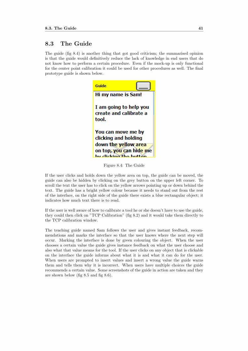
The guide (fig 8.4) is another thing that got good criticism; the summarised opinionis that the guide would definitively reduce the lack of knowledge in end users that donot know how to perform a certain procedure. Even if the mock-up is only functionalfor the center point calibration it could be used for other procedures as well. The finalprototype guide is shown below.
Figure 8.4: The Guide
If the user clicks and holds down the yellow area on top, the guide can be moved, theguide can also be hidden by clicking on the grey button on the upper left corner. Toscroll the text the user has to click on the yellow arrows pointing up or down behind thetext. The guide has a bright yellow colour because it needs to stand out from the restof the interface, on the right side of the guide there exists a blue rectangular object; itindicates how much text there is to read.
If the user is well aware of how to calibrate a tool he or she doesn’t have to use the guide,they could then click on ”TCP Calibration” (fig 8.2) and it would take them directly tothe TCP calibration window.
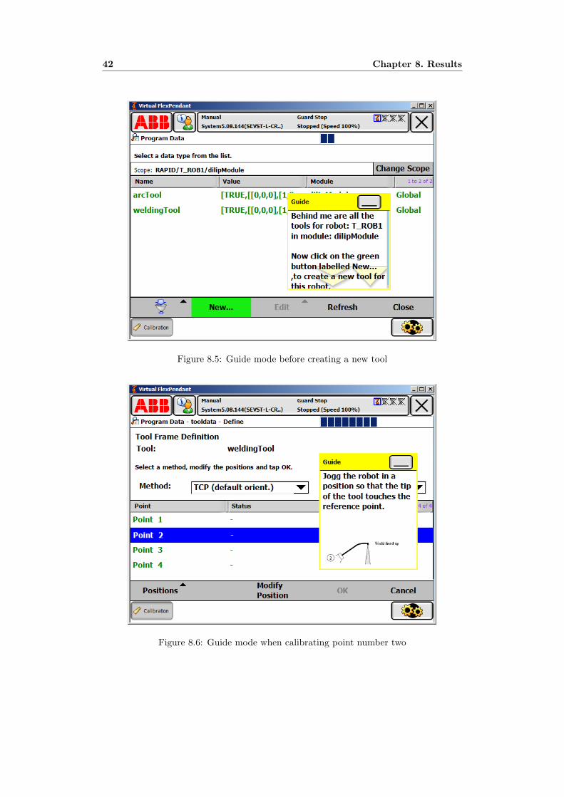
The teaching guide named Sam follows the user and gives instant feedback, recom-mendations and marks the interface so that the user knows where the next step willoccur. Marking the interface is done by green colouring the object. When the userchooses a certain value the guide gives instance feedback on what the user choose andalso what that value means for the tool. If the user clicks on any object that is clickableon the interface the guide informs about what it is and what it can do for the user.When users are prompted to insert values and insert a wrong value the guide warnsthem and tells them why it is incorrect. When users have multiple choices the guiderecommends a certain value. Some screenshots of the guide in action are taken and theyare shown below (fig 8.5 and fig 8.6).
42 Chapter 8. Results
Figure 8.5: Guide mode before creating a new tool
Figure 8.6: Guide mode when calibrating point number two

Chapter 9
Discussion
This chapter discusses the thesis, what the thesis is about but more importantly what thethesis is not about.
This thesis discusses the different problems within robot calibration with a focus onusability. The prototype has restructured the calibration interface so that it seems moreintuitive to the user. The prototype also includes a guide with the main purpose ofhelping and assisting the user to perform a certain type of calibration called tool centerpoint, the prototype also includes text viewing so that the user don’t need to consultpaper form manuals.
Even though some ideas have been implemented, far from every idea presented in thisthesis to improve the usability is implemented. The ideas not implemented are howeverdiscussed and solutions are presented.
The focus on usability in this project is taken on a bigger perspective, meaning thatthings like colour, contrast, icons, etc are not taken in consideration. Even though forinstance buttons are placed in the right ”window” and in the order the correspondingoperations should be performed in, it has not been considered exactly where in the”window” they should have been placed.
These things have not been taken into consideration because the author believes thatwhen working with usability in an application there are more important things to con-sider (structure, feedback, consistency, etc) than what colour to use, what the icons looklike, exactly where the buttons are placed, etc. These things are also important but notin the initial stage of a prototype.
43

44 Chapter 9. Discussion

Chapter 10
Conclusions
This chapter draws conclusions of the thesis, presents limitations on the mock-up anddiscusses the future work that the author believes ABB should look into.
The two main calibration problems dealt with are the tool center point calibrationand the work object calibration.
The problems concerning tool center point calibration are how to perform a TCP cali-bration and how to reduce the time it takes to perform it, how to make the end usersrealize why they need an accurate TCP and how to give better feedback to the userwhen a TCP calibration is performed. The performing time would be reduced by savingthe TCP points and the robots movement from the initial installation and then use thepoints and movements for next coming calibration; by saving the points better feedbackcould be given to the user. The text viewer implemented in the mock-up would helpend users realize that an accurate TCP is crucial.
The other main calibration problem discussed in this thesis is work objects; the biggestproblem is the lack of knowledge in the user about how or why they should use thetechnique. Users that recalibrate work objects have trouble with knowing where theyare placed and why they are positioned in a certain way. The guide and the text viewerwould solve the user’s lack of knowledge; the guide teaches the user how to perform awork object and the text viewer explains why the user needs work objects. Saving workobject points in the initial setup would help users that recalibrate work objects, sincethe robot can show them where the work object was originally put. Having text andpictures included into every work object would solve the question why and how they areplaced.
By adding the text viewer user’s can read about different techniques in a rather easyway and gain some knowledge about why one should calibrate a certain way and howto calibrate the methods. The guide on the other hand acts like a tutor that never getsbored and helps the user any time of the day. The guide helps, gives instant feedbackand recommendations to the user.
45

46 Chapter 10. Conclusions
10.1 Limitations
The prototype guide is not implemented to work for a work object calibration.
10.2 Future work
Work object points should be saved; reasons are mentioned in chapter 7. The TCPpoints and the robots movement from the initial TCP calibration should also be saved;reasons are mentioned in the chapter 7. The counter method explained in chapter 7 thatlets the operator know how long it is left to the next robot target is highly recommendedto look into.
A PDF viewer would be better than the implemented text viewer because the PDFmanuals could be directly downloaded to the controller and features like search andzoom would be available.
Let the user know how the work object is placed on the fixture needs to be lookedinto. Pictures explaining where the markings are for every axis when updating revolu-tion counters would be helpful for the user, and should therefore also be looked into.Warnings in the form of a pop-up would definitively help users understand that someprocedures are highly recommended by ABB to perform.
Implementing a best fit method that automatically could reposition all robot targetsin a program after the user has touched up a couple of targets would be a huge timesaver for a installation technician, this is explained more in detail in chapter 7.

References
[1] ABB. BaseWare User’s Guide BW OS 4.0.60. ABB, ABB Automation TechnologiesAB Robotics SE-721 68 Vasteras Sweden, 3hac7793-14060 edition, 2003.
[2] ABB. RAPID reference manual. ABB, ABB Automation Technologies AB RoboticsSE-721 68 Vasteras Sweden, 3hac16580-1 edition, 2003.
[3] ABB. Getting Started IRC5 and RobotStudioOnline. ABB, ABB Automation Tech-nologies AB Robotics SE-721 68 Vasteras Sweden, 3hac021564-001 edition, 2004.
[4] ABB. Operating manual IRC5 with FlexPendant. ABB, ABB Automation Tech-nologies AB Robotics SE-721 68 Vasteras Sweden, 3hac16590-1 edition, 2006.
[5] B. Attkinson. Ibm intelligent agents. 1995.
[6] Amy Baylor. Beyond bulters: Intelligent agents as mentors. Educational ComputingResearch, 22(4):373–382, 2000.
[7] D. Christopher Dryer. Wizards, guides, and beyond: rational and empirical meth-ods for selecting optimal intelligent user interface agents. In IUI ’97: Proceedingsof the 2nd international conference on Intelligent user interfaces, pages 265–268,New York, NY, USA, 1997. ACM Press.
[8] Oren Etzioni. Moving up the information food chain: Deploying softbots on theworld wide web. In Proceedings of the Thirteenth National Conference on Arti-ficial Intelligence and the Eighth Innovative Applications of Artificial IntelligenceConference, pages 1322–1326, Menlo Park, 4–8 1996. AAAI Press / MIT Press.
[9] Jensen Harris. Tipping the scale (why the ui, part 5). Blog, April 04 2006.http://blogs.msdn.com/jensenh/archive/2005/10/24/484131.aspx.
[10] Jensen Harris. Ye olde museum of office past (why the ui, part 2). Blog, March 292006. http://blogs.msdn.com/jensenh/archive/2006/03/29/563938.aspx.
[11] Ted Selker Henry Lieberman. Agents for the user interface. MIT Press, 2003.
[12] Alan Kay. User interface: A personal view. in: The art of human-computer interfacedesign. Addison-Wesley, 1990.
[13] Henry Lieberman. Autonomous interface agents. In CHI 97: Proceedings of theSIGCHI conference on Human factors in computing systems, pages 67–74, NewYork, NY, USA, 1997. ACM Press.
47
48 REFERENCES
[14] Pattie Maes. Agents that reduce work and information overload. pages 811–821,1995.
[15] Stuart E. Middleton. Interface agents: A review of the field. Technical ReportECSTR-IAM01-001, University of Southampton, 1999.
[16] Donald T. Roesler, Marina; Hawkins. Intelligent agents: Software servants for anelectronic information world (and more!). CODEN ONLIDN, 18(7):18–32, 1994.
[17] Ira Rudowsky. Intelligent agents. 2004.
[18] Ted Selker. Coach: a teaching agent that learns. Commun. ACM, 37(7):92–99,1994.
[19] Ben Shneiderman. Direct manipulation. a step beyond programming languages.IEEE Transactions on Computers, 16(8):57–69, August 1983.
[20] Ben Shneiderman and Pattie Maes. Direct manipulation vs. interface agents. in-teractions, 4(6):42–61, 1997.
[21] Paul Thurrott. Office 2007 public beta now available. Internet, May 22 2006.http://www.winsupersite.com/showcase/office2007 public beta.asp.
[22] Reinout van Schouwen. User interface agents: a comparison.
[23] Michael Winikoff, Lin Padgham, and James Harland. Simplifying the developmentof intelligent agents. In AI ’01: Proceedings of the 14th Australian Joint Conferenceon Artificial Intelligence, pages 557–568, London, UK, 2001. Springer-Verlag.
Appendix A
Field Study Questions
– Tell me a little about your self, your background and experience with ABB robotsand calibration.
– Why is it that users don’t use work objects? (Apparently only 10 out of 500 inFrance knows about work objects and its functionality)
• Hard to perform?
• Hard to understand?
– What can ABB do to make the technique easier to use?
– What kind of problems can be encountered when calibrating a tool center point?
– What can be done to make the tool center point calibration easier to use?
– What kind of problems does an installation technician encounter when doing arobot installation? (Focus on the robot calibration)
– How can ABB best help/assist the technician?
– Are wizards, guides and the like a good way to ease the ”knowledge load” on theuser?
– Which methods/techniques need to be developed by ABB to make calibrationeasier, faster and more usable in the future?
49