USAAFAT9SA NL I flfflfllflfll//l EIIIIEIIIIEEI · SCHEDULE 16. DISTRIBUTION STATEMENT ... V IBR EX...
67
AC-AIDS 121 ARMY AVIATION ENGINEERING FLIGHTY ACTIVITY EDWARDS AFB CA F/6 1/3 ICE Pt405ICS BLADE TRACKCING AND COMPARISON OF VIBRATION ANALYSIS--ETC(U) MAY 51 V Y ABBOTT, F L DOMINICK. S ARTHUR UNCLASSIFIED USAAFAT9SA NL *""EEI/EE I flfflfllflfll//l EIIIIEIIIIEEI lllllllllEND
Transcript of USAAFAT9SA NL I flfflfllflfll//l EIIIIEIIIIEEI · SCHEDULE 16. DISTRIBUTION STATEMENT ... V IBR EX...

AC-AIDS 121 ARMY AVIATION ENGINEERING FLIGHTY ACTIVITY EDWARDS AFB CA F/6 1/3ICE Pt405ICS BLADE TRACKCING AND COMPARISON OF VIBRATION ANALYSIS--ETC(U)MAY 51 V Y ABBOTT, F L DOMINICK. S ARTHUR
UNCLASSIFIED USAAFAT9SA NL*""EEI/EE
I flfflfllflfll//lEIIIIEIIIIEEI
lllllllllEND

V fit . 1128 11112.
11111 1.1112.0
MICROCOPY RESOLUTION TEST CHARTIYAIONA[ 8UfRI AJP 0F STANDAILIPS 1%( A

USAAEFA PROJECT NO. 79-86
ICE PHOBICS BLADE TRACKING ANDCOMPARISON OF VIBRATION ANALYSIS TECHNIQUES
FINAL REPORT
FLOYD L. DOMINICKWILLIAM Y. ABBOTT PROJECT OFFICERPROJECT ENGINEER STUART ARTHUR
PROJECT ENGINEER
MAY 1981
DTICELECTE
DEC 4 1981
0 Approved for public release; distribution unlimited. SQ00
SUNITED STATES ARMY AVIATION ENGINEERING FLIGHT ACTIVITYEDWARDS AIR FORCE BASE, CALIFORNIA 93523
0,L,..09
r
DISCLAIMER NOTICE
The findings of this report are not to he construed as an official Department ofthe Army position unles so designated by other authorized documents.
DISPOSITION INSTRUCTIONS
Destroy this report when it is no longer needed. Do not return it to the originator.
TRADE NAMES
Tise one of trade names in this report does not constitute an official endorsementor approval of the ease of the commercial hardware and software.
.1
I 9_______________....._________1

UNCLASSIFIEDSECURITY CLASSIFICATION OF THIS PAGE (Ifwai Entered)
PAGE READ INSTRUCTIONSREPORT DOCUMENTATION PAEBEFORE COMPLETING FORM1. REPORT NUMBER 12. GOVT ACCESSION NO. 3. RECIPIENT'S CATALOG NUMBER
USAAEFA 4RO-1I*T NO,. 79-86 L iA ID? .. 2~4. TITLE (and Subtitle) S. TYPE OF REPORT & PERIOD COVERED
ICE PHOBICS BLADE TRACKING AND COMP3ARISON FINAL REPORTOF VIBRATION ANALYSIS TE-CHNIQUES JUNE 1979 - MARCH 1980
6. PERFORMING ORG. REPORT NUMBER
7. AUTHOR(s) 6. CONTRACT OR GRANT NUMBER(s)
WILLIAM Y. ABBOTT FLOYD) L. D)OMINICKSTUART ARTHUR
9. PERFORMING ORGANIZATION NAME AND ADDRESS 10. PROGRAM ELEMENT. PROJECT, TASKAREA & WORK UNIT NUMBERS
US ARMY AVIATION ENGINEERING FLIGHT ACTIVITYEDWARDS AIR FORCE BASE, CALIFORNIA 93523
I I. CONTROLLING OFFICE NAME AND ADDRESS 12. REPORT DATEUS ARMY AVIATION RESEARCH AND MY18DEVELOPMENT COMMAND A 184300 GOODFELLOW BOULEVARD III. NUMBER OF PAGESST. LOUIS, MISSOURI163120 64
14. MONITORING AGENCY NAME & ADDRESSI diff.eent from, Controlling Office) IS. SECURITY CLASS. (of this report)
UNCLASSIFIEDIS&. DECL ASSI FICATION/ DOWNGRADING
SCHEDULE
16. DISTRIBUTION STATEMENT (of this Report)
Approved for public release; distribution unlimited.
17. DISTRIBUTION STATEMENT (of the abstrael entered In Block 20, If different fromn Report)
IS. SUPPLEMENTARY NOTES
19. KEY WORDS (Continu, an reverse side if necoeary and Identify by block number)
4' Ice Phobic CoatingScientific-Atlanta Signature RecorderI Vibration
4 AM ABSTRACT l"Cosmzure si revorse an1~~eysd Identify by block 1W15,bst)The United States Army Aviation! !Engineering Flight tivity conducted an evaluation of twovibration measuring devices, the Chadwick-Helmuth VIB EX and the Scientific-Atlantat VibrationSignature Recorder, as flight test instruripentation. Durn the course oif those evaluations, it wasdetermined that the Dow Corning E2460-40-1lrdsga E984Yc phobic coatino applied tothe rotor blades of a UK- I H helicopter, did not induce unilesirable vibrations. It was also concludedthat the VIBREX may be used as test instrumentation thr theF frequendis 4. ineei lite alreadyknown, and the Scientific-Atlanta dlevice provides good "quick look" spectr~i vibration data1
- DO iMi 1473 EDITION OF I NOV 65, IS OSOLETE IhPG
JAN 73UCAS1It

TABLE OF CONTENTS
INTRODUCTION
Background ............................................... ITest O bjectives ............................................ IDescription ............................................... I
A ircraft .............................................. I
Ice Phobics ........................................... IVIBREX System ....................................... 2Vibration Signature Recorder ............................. 2
Test Scope ................................................ 2Test Methodology .......................................... 6
RESULTS AND DISCUSSION
G eneral .................................................. 7Ice Phobics ............................................... 7V IBR EX ................................................. 7Scientific-A tlanta .......................................... 1 2Pilot Comments versus Data .................................. 14Comparison of Vibration Analysis Methods ...................... 14
CONCLUSIO NS ............................................... 19
APPENDIXES
A . References ................................................ 20B. Description ............................................... 21C. Instrum entation ........................................... 27D. Data Analysis Methods ...................................... 28E. Test Data ................................................. 30
DISTRIBUTION
ecession ForLWTTS G;RA&ITBDTICDTIC TAB0
Unannounoed []
Justitfict _ .. ELECTE
Distribution/
Availability Codes DAvail and/or
Dist Spcial

INTRODUCTION
BACKGROUND
I. In January 1978, the United States Army Aviation Engineering Flight Activity(USAAEFA) evaluated Dow Coming Corporation's 12460-40-I ice phobic coatingon the rotor blades of a till-Ill helicopter (Reference I, Appendix A). 'he purposeof the coating is to provide a surface to which ice will not adhere. After theevaluation was completed, the helicopter developed intermittent one per revolutionvibrations that maintenance personnel had difficulty removing. Speculation was thatthis vibration was related to the use of the ice phobic coating.
2. In June 1979, USAAEFA assigned its Advanced Methodology and AnalysisOffice to investigate any vibration problems associated with the coating. Also,during the investigation, an evaluation was to be made of two relatively newvibration measuring devices.
TEST OBJECTIVES
3. The objectives of this test were to
a. Determine if the Dow Coming E2460-40-I ice phobic coating inducesundesirable vibrations when applied to the main rotor blades of a UH-IHhelicopter
h. Evaluate the effectiveness and accuracy of the Chadwick-HelnuthVIBREX Balancing Kit (hereafter referred to as VIBREX) as both a vibration sensor,and as an aid to balancing and tracking the main rotor
c. Evaluate the Scientific-Atlanta Vibration Signature Recorder (VSR) as avibration measuring device
d. Compare the results of the two vibration measuring devices with resultsobtained from the USAAEFA spectral analyzer and with the newly written fastFourier transform (FFT) computer program
e. Compare pilot's opinion of vibration severity using the Vibration RatingScale (VRS) with data from the various recording devices.
DESCRIPTION
Aircraft
4. The test aircraft was a JUH-IH, US Army serial number 69-15532. Vibrationdata (accelerations) were recorded along with other aircraft parameters on the PCMtrack of the on-board tape recorder. Accelerations were also recorded on the FMtrack. A detailed description of the standard UH- I H is contained in the operatorsmanual (Reference 2).
Ice Phobics
5. The Dow Coming E2460-40-1 (redesignated E2978-46) ice phobic coatingis a cationic silicone base liquid with a viscosity comparable to that of SAE10 weight oil. The coating may be applied using spray, brush, roller, etc. During this

evaluation, the coating was sprayed on and any irregularities were removed with acloth.
VIBREX System
6. The VIBREX Balancing Kit, manufactured by Chadwick-lfelmuth Company,Inc. of Monrovia, California is used to measure and indicate the level of vibrationsinduced by the main and tail rotors of a helicopter. The VIBREX analyzes thevibration caused by out-of-track, or out-of-balance; and then, by plotting vibrationamplitude and peak amplitude azimuth (clock angle) on a chart, the amount andlocation of rotor track or weight changes can be determined.
7. The VIBREX system consists of two parts: the Balancer/Phazor, and theStrobex. The Balancer/Phazor is contained in a box 8.125 inches by 8.375 inches by2.25 inches and weighs approximately 4 pounds (Figure 1). The key feature of thisunit is a tuneable electronic bandpass filter which is tuned to reject all but onefrequency of vibration under study. The meter reads the amplitude of vibration (ininches per second) at the frequency of concern. The Phazor section contains a phasemeter that reads clock angle, or phase angle, relative to a one per revolution signalfrom the rotor and the vibration signal from an accelerometer.
8. The Strobex tracker (Figure 2) is a small (6.0 by 4.25 by 5 inches) hand heldcombination power supply and strobe flash tube weighing 5 pounds. It illuminatesreflective targets on the tall rotor to measure tail rotor clock angle, or the mainrotor to indicate rotor track and lead-lag. Further description of the VIBREXsystem is in Reference 3, and Appendix B.
Vibration Signature Recorder
9. The Vibration Signature Recorder Model 2538, is manufactured by the NewJersey Division, Scientific-Atlanta, Inc., of Randolph Township, New Jersey(Figure 3). The VSR is contained in a box 10.25 by 14.25 by 10 inches, and weighs18 pounds. The signals from an accelerometer are fed into the recorder, and a plotof vibration velocity versus frequency is produced on a 4 by 6 inch card. The entireprocess takes approximately 60 seconds per accelerometer. A more detailed descrip-tion is contained in Reference 4, and Appendix B.
TEST SCOPE
10. The flight evaluation was conducted at Edwards Air Force Base, California(2303 foot elevation) from June 1979 through March 1980. A total of 29.7 hourswere flown. Typical flight conditions were as follows:
Main rotor speed 324 RPMLongitudinal center of gravity FS138 (Mid)Density altitude 6000 ftGross weight 8000 lbIndicated airspeed 0, 50, 80 and 100 knots
2
' Al

A.1L 1 NEL
ompaommT TRAC-^ -METER
ulvk~mwi BALANCER=-Z- 0-ft MODEL 177M-GA(.
Ina -- BAND PASSMAXE n i
-oo O FILTER
0 PIA KANNe vIWv TNEsu(l)
DJOUBLE & I(
PH)ZOR PHASEPHAZA30 METER
FIGURE I. VIBREX BALANCER/PHAZOR
3

DICMAL
DIA
FLASH STROBEXTUBE MOEL 135M-11
FIGURE 2. STROBE
4
...... ........ ... .... .......

FIGURE 3. MODEL 2538 VIBRATION SIGNATURE RECORDER
NN

TEST METHODOLOGY
11. The aircraft was flown at specified airspeeds and vibration data were recorded(luring hover and unaccelerated level flight. Test procedures arc doscribed in thieResults and Discussion section of this report. A detailed list of the test instrumen-tation is shown in Appendix C, and the data analysis methods are shown inAppendix D.
6

RESULTS AND DISCUSSIONGENERAL
1 2. The aircraft was flown in hover and at indicated airspeeds of 50, 80. and100 knots. The data from various sources were reduced, and plots were made usingthe harmonic format. The harmonic plots shown in Appendix E are labelednumerically and alphabetically, with lateral and vertical accelerations labeled A andB res~pectively.
ICE PHOBICS
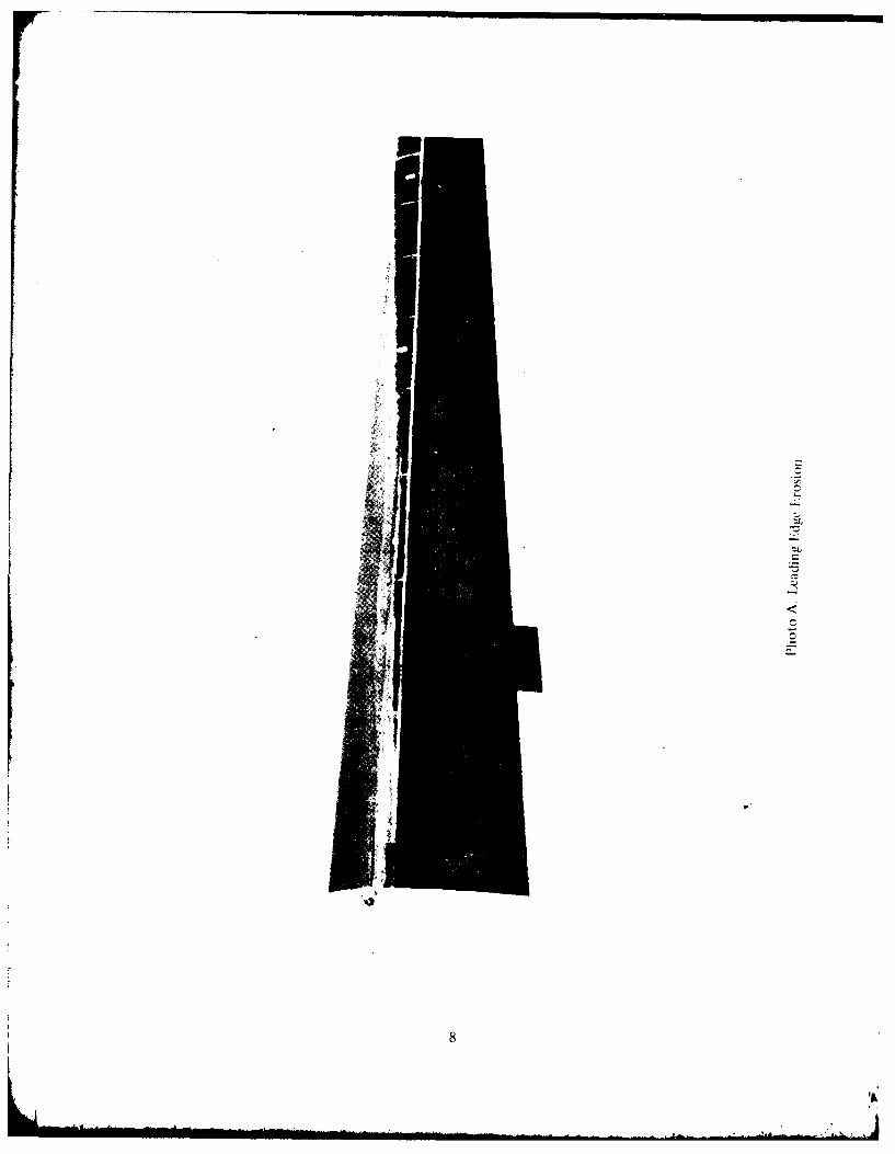
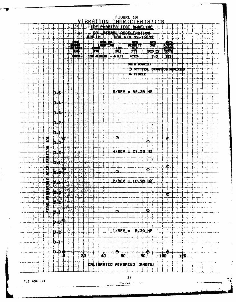
13. Thle aircraft was first flown with no ice phobic su bstancc applied to the blades.The data from this flight was used as the baseline (Figures I A and I B). Then, acoating of ice phobics was applied, and the aircraft flown under similar conditions(Figures 2A and 2B). The ice phobic was then removed, and a fresh coat applied.The aircraft was hovered in a dusty environment, and then flown in level flight(Figures 3A and 3B). Finally, the ice phobics was again cleaned off, and the aircraftwas flown as a baseline for subsequent blade tracking tests (Figure 4A and 4B).Qualitative pilot comments, and quantified pilot comments using the VRS, showedno change during any of the four flights. Examination of the data recorded on thleFM data track and processed through the Spectral Dynamics Analyzer showed aslight decrease in vibration level when the ice phobic was applied and flown in aclean environment. The data of the ice phobic in a dusty environment showedcharacteristics virtually identical to the before and after baseline flights.Examination of the blades subsequent to the flight in the dusty environment showedthat the ice phobics had been effectively sand blasted off (Photo A and B). Certainsnow or ice particles could produce the same effect which would decrease theprotection as a flight continued.
VIBREX
14. The VIBREX is marketed as a maintenance tool rather than as an analyticalinstrument. One-per-revolution vibration velocity and clock angle are read off theBalancer unit and plotted on charts such as shown in Figures 4 and 5. Verticalvibrations are symptomatic of a faulty track condition, and corrected by change inpitch link length or tab angle. Lateral I/rev vibrations are normally symptomatic ofchordwise or spanwise unbalance and may be corrected by adding or subtractingweights at specific locations, or adjusting the sweep of the blades. The angularorientation and linear scaling of the charts are determined by the mechanicalresponse of the airframe at the accelerometer location, to the rotor. The chartsshown have been determined by the manufacturer to be appropriate for the UK-Imodel aircraft in general. If precise tracking/balancing information is desired, aspecific chart would have to be made for each particular aircraft at only one grossweight, moment of inertia, and accelerometer location. In practice, however, thecharts are used to determine the direction of adjustment required, and onlyapproximation of the magnitude of the adjustment. This becomes especially evidentwhen it is understood that to minimize vibration at one airspeed will not necessarilyminimize vibration at another airspeed. Therefore, a compromise is normally madewhereby vibration is minimized at hover and a typical mission airspeed. Figure 4shows the fairly typical data scatter with airspeed. The actual pitch link adjustmentrequired for the flight shown in Figure 4 was +1 nut flat of turn.
7
8
fpj

14I
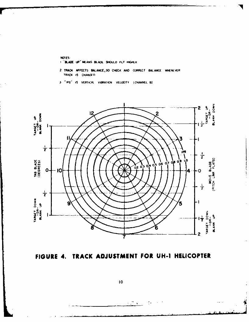
Nol ES:I "LADE UP" MEANS SLADE SHOUJLD FLY HIG*t
2 TRACK AFFECTS BALANCE, SO CHECK AND CORRECT BALANCE WHENEVERTRACK IS CHANGED
3 IPS" S VERliCAl VIBRATION VELOCITY (CmANNEL 8)
Ia
22
hh0
FIUR 0- . 4-C DUTETFO H1HLCPE
0 I0

NOTES;00D NOT ATTEMPT 'TO BALANdCE UNLESS SHIP IS IN G0OD HOVER TRACK
2 THE AMOUNT OF WEIGHT OR SWEEP REQUIRED MAY BE SOMLWHAT DIFFERENTFOR THE VARIOUS MODELS OF UNH- I HLILICOPTER
3 IPS" IS HORIZONTAL VIBRATION VELOCITY (CHANNEL A)
WEIGHT CHANGE SHOULD GENERATEA MOVE LINE IN THIS DIRECTION s
IL
18 '
Q uh
LX 0
Z1 W
09-6
hi0
0
O4 (k U.
a. >uJO0
a: cr
1500 1000 500 0 500 1000 1500ADD TO TARGET WEIGHT IN ADD TO BLANK
-OR- BL ADE SOLT -OR-SUBTRACT FROM BLAN4K -GjRAMS- SUBTRACT FROM TARGET
FIGURE S. BALANCE ADJUSTMENT FOR UH-1 HELICOPTER

15. The VIBREX was evaluated by beginning with the rotor in the best track andbalance possible. Then, the blade was brought out of track by changing the pitchlinks or tabs a specified amount. The aircraft was flown at the four airspeeds,and the VIBREX data was plotted on Figure 4. Since track may be corrected bychanging either the tabs or the pitch links, a priori knowledge was used indetermining the corrections shown in Figure 6. Generally, results from the VIBREXshowed excellent agreement with the adjustments actually made.
F*~ re 0VIBREX racking Data
Figure in VIBRFX Indicated ActualAppendix E Problem Problem
4 0 05 +1 Flats (Pitch) +1 Fats (Pitch)6 +2 Flats (Pitch) +2 Flats (Pitch)7 -1/2 Flats (Pitch) -1 Flats (Pitch)8 -1/2 Flats (Pitch) -1 Flats (Pitch)9 0 +3/4 Flats (Pitch)
10 0 0II +1/20 (Tab) +I* (Tab)12 +1-1/2 0 (Tab) +20 (Tah13 -I -1/4* (Tab) -1 0 (Tab)14 - /2" (Tab) 0
6. Because or the data scatter with airspeed, the use of thc charts to determine theremedy for an out-of-track/out-of-balance situation is somewhat of an "art". This ismade more evident by the fact that changing track affects balance and vice versa.However, the VIBREX, used as a maintenance tool, is a useful aide in correcting ofout of track problems. No tests were conducted to specifically examine the abilityof the VIBREX to correct out of balance problems. The use of the VIBREX as avibration measuring device will be discussed later in this section.
SCIENTIFIC-ATLANTA
17. The Scientific-Atlanta VSR, like the VIBREX, is designed primarily as amaintenance tool. It is intended that a history of the aircraft vibration signature bekept, and any noticeable change in signture will cue maintenance personnel to beon the alert for problems in particulai areas. The spectral signature (vibrationvelocity versus frequency), is plotted on a preprinted 4 by 6 inch file card(Figure 7). Various color pens are available, so that lateral and vertical vibrationsmay be plotted on a single card.
18. The VSR is an almost ideal instrument to record "quick look" test data. It ishighly portable, can be operated by unskilled personnel, and the format of theoutput is what is normally required for analysis. A comparison of the VSR data(shown in Figure IOA through I IB, Appendix E) with other methods is presentedlater in this section.
12
.7'.-

N'~*~*Scientific -Atlanta, Inc. New je..ey Di,-o.......
-7f -- ICAIW0N
8------ - FE~~AMI........- -
uJ - -
0 Z
,, _j -- 1-4 -10 4 0 6 7 0 9
FIUR 7. SA L VR OUPU
.13

PILOT COMMENTS VERSUS DATA
19. During the flights, four test pilots were requested to evaluate the vibration levelin accordance with the VRS shown in Figure 8. Preliminary plots were made of theVSR versus the vibration amplitudes obtained by the Spectral Dynamics analyzer.No meaningful correlation could be found. The sensors for the instrument measuredvibrations were located near the aircraft center of gravity: more than 7 feet fromthe seats. It was concluded that the dynamic response of the aircraft structure issuch that vibration measurements at the center of gravity are not representative ofvibrations at the front seats. The correlation of vibration data with the VRS is still asubject of interest, and it is recommended that such a study be undertaken byUSAAE* in a properly instrumented aircraft.
COMPARISON OF VIBRATION ANALYSIS METHODS
20. Within the past decades, vibration analysis at USAAEFA has beenaccomplished through the use of a hardware spectral analyzer (Spectral DynamicsModel SD301C with a Mod ' SD302B ensemble averager) or the FM data track(Appendix D). The output of tne analyzer is a spectral plot showing either level (dB)or amplitude (g) versus frequency (Figure 9). For convenience, amplitude isnormally requested; however, level was requested for this test because of theincreased resolution possible with that scale. The level from the spectral plot mustbe manually converted to peak acceleration (g) for the frequencies of interest.
21. The accelerometers used on the FM track were also recorded on PCM (througha 20 Hz filter). Time history plots of random points were made from the PCM data(Figure 10) and were used to corroborate the 2/rev FM results. The two methodsyielded virtually identical results in all caws checked.
22. It was originally intended that the PCM data be computer-processed using aFFT program recently written at USAAEFA. However, errors in the program werediscovered, and time constraints precluded the possibility of waiting for the programto be corrected. Because most of the test data processed at USAAEFA is on PCM, itis apparent that computing vibration parameters using digital methods from the PCMtrack would offer many advantages. Most important, vibration data would be takenat precisely the same time as other data, and any manipulation of the data could behandled easily in the computer. It is intended that work on the digital methods becontinued and that it will be used in first preference if accuracy proves to becomparable to that of the spectral analyzer.
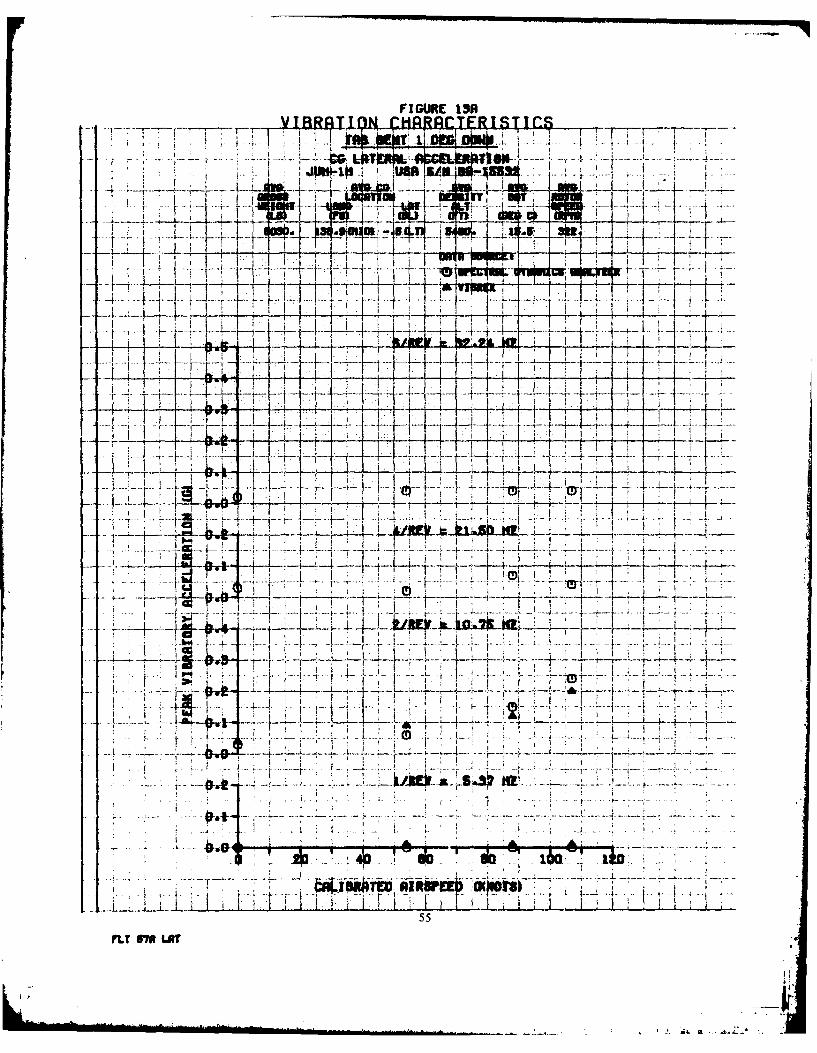
23. Using the VIBREX as a vibration measuring instrument, it is necessary to "dialin' the frequency of interest, and record the magnitude shown on the meter.Although this is time consuming and awkward, it was done during this evaluation.and the results shown in Figures IA through 14B in Appendix I-. One per revvibrations were so low that no meaningful comparison can be made of the data. Thevertical results of the VIBREX show a bias of approximately +0.1 G on 2/rev and+0.05G on 4/rev compared to the spectral analyzer. The lateral results showedgood agreement with the analyzer. The trends shown by the VIBREX data on bothaxes closely resembled the trends of the analyzer data.
14

0
uiIMEu.mmaEI.e 0
> 0 ( .cQ
- 0 E- 1%
0, 04
C-C C- 1
g~0 >
Ca L
wj 0
wj .-
2~ J5

0> 1
N
w
am
MA
IL
'-4
NOIY1401 333? I4OIJNHVIA IV31.IM3A
16

.00
- 0
0000
row
.00010
LO 0 t n 0 i 0- o 0 t o 0 % 0 in '
0~~~- .-f -4 -4 4 -1 14 0 0 0 0 0
NO~lN3133Y VOII3A NIIVSI30V IV31V
17m

24. The Scientific-Atlanta VSR was used on only two flights (Figure 1 OA throughI I B, Appendix E). Despite some scatter at 6/rev, the data compare well with thespectral analyzer in both axes. Also, the ease with which the VSR can be used in atest environment makes it a valuable "quick look" instrumentation device.
18

CONCLUSIONS
25. The Dow Coming E2460-40-1 (redesignated E2978-46) ice phobic coating hasno adverse effects on helicopter vibration (para 13).
26. The Chadwick-Helmuth VIBREX accurately determined corrections to bemade to correct out of track conditions (para 15).
27. A digital technique for vibration analysis using PCM data would be a significantadvantage over current methods (para 23).
28. The VIBREX is difficult to use as a vibration measuring instrument unless thefrequencies of interest are already known (para 23).
29. The trends shown by VIBREX data closely resembled the trends of the datafrom the spectral analyzer (para 23).
30. The Scientific-Atlanta Vibration Signature Recorder gave results which closelycompared to data from the spectral analyzer (para 24).
31. The Scientific-Atlanta VSR is very easy to use (para 24).
19
l .. . . ..- . , ... . . .... . . .. ... , _. ... .. . . . . . . . . ...-. . . . .. _ ' . . . : . . . , ".a '. ' h - '
"

APPENDIX A. REFERENCES
I. Final Report, USAAEFA, Project No. 77-30, Artificial Icing Test, Ice PhobicCoatings on UH-IH Helicopter Rotor Blades, June 1978.
2. Technical Manual, TM 55-1520-210-10, Operators Manual, Army ModelUII-ID/Il Helicopters, 25 August 1971, with Change 18.
3. Preliminary Technical Manual, TM 55-4920-402-13&P, Operating Instructions,Aviation Unit and A iPation Intermediate Maintenance Manual, VIBREX BalancingKit, 15 March 1978.
4. Manual, Scientific-Atlanta, Inc., Model 2538 Vibration Signature Recorder,Instruction Manual.
5. Training Course and Application Notes, Spectral Dynamics Corp., Theory,Troubleshooting, and Calibration of Real Time Analyzer Instruments, March 1972.
20

APPENDIX B. DESCRIPTION
VIBREX
I. The VIBREX Balancing Kit (hereafter relfrrtd to as VIBRLX) is used tomeasure and indicate the level of vibrations induced by the main rotor and tail rotorof a helicopter. The VIBREX analyzes the vibration induced by out-of-track, or out-of-balance rotors, and then by plotting vibration amplitude and clock angle on achart, the amount and location of rotor track or weight changes is termined. Inaddition, the VIBREX is used in troubleshooting by measuring the revolutions-per-minute (RPM) or frequency of unknown disturbances.
2. The VIBRFiX is housed in a Carrying ('ase and consists of the coilponcillslisted in Table B-I. The main units of the VIBREX are Balancer/Phazor 177M6A,Strobex Tracker 135M1 I, and VIBREX Tester 11. The primary airframe mountedcomponents are three Accelerometers 4177B and two Magnetic Pickups 3030AN.
a. Balancer/Phazor ! 77M6A. The key feature of the Balancer/Phazor (here-after referred to as Balancer) is a tuneable, electronic bandpass filter which is tunedto reject all but one frequency, or vibration under study. The meter reads the levelof vibration at the rate (RPM) of concern, which is indicative of thc amount of therequired change (track or balance). The Phazor section contains a phase meter thatreads clock angle, or phase angle, between a one-per-revolution Magnetic Pickupazimuth signal from the rotor and a vibration signal from the Accelerometer.
b. Strobex Tracker 135M1 I. The Strobex Tracker (hereafter referred to asStrobex) is a small hand held lightweight combination power supply and strobe flashtube. It illuminates reflective targets on the tail rotor to measure tail rotor clockangle, and on the main rotor to indicate rotor track and lead-lag.
c. VIBREX Tester I I . The VIBREX Tester (hereafter referred to as Tester)provides accurate calibration and complete functional check of the VIBRtX. TheTester shakes (vibrates) the Accelerometer to measure vibration amplitude in inches-per-second (IPS) and rate (RPM) functions of the balancer. Phase or clock anglefunctions of the Phazor section are verified by a rotating interrupter plate andthe Magnetic Pickup to provide double and single interrupter logic singals. The RPMdial of the Strobex is accurately checked against the known rotor speed of theTester motor.
d. Accessories Following is a list of accessories that are used with theBalancer, Strobex, and Tester:
(1) Magnetic Pickups and Interrupter Sets. Pickup device to providemagnetic impulses from rotor to Balancer. Magnetic pickups are located on rotatingplatforms while Interrupter Sets are located on stationary platforms.
(2) Accelerometers. Provides the Balancer with an electrical represen-tation of the physical motion of the point to Which it is attached.
(3) Reflective and Tip Target Sets. Reflects Strobex flash pulses back toStrobex operator.
(4) Balance and Tracking Charts. Used to calculate weight, sweep, pitchlink, tab, etc., to correct rotor problems.
21
" -
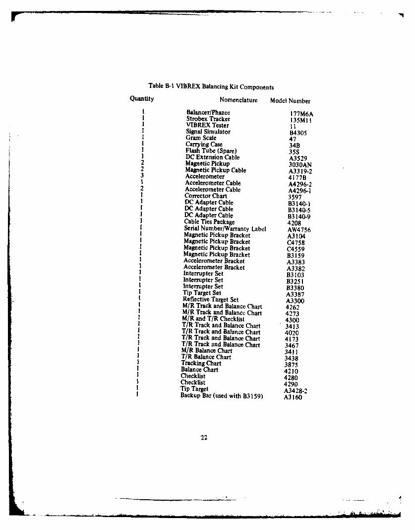
Table B-I VIBREX Balancing Kit Components
Quantity Nomenclature Model Number
I Balancer/Phazor I 77M6AI Strobex Tracker 1 35M] II VIBREX Tester I II Signal Simulator 8430SI Gram Scale 47I Carrying Case 34BI Flash Tube (Spare) 35SI DC Extension Cable A35292 Magnetic Pickup 3030AN2 Magnetic Pickup Cable A3319-23 Accelerometer 4177BI Accelerometer Cable A4296-22 Accelerometer Cable A4296-1I Corrector Chart 35971 DC Adapter Cable B3140-1I DC Adapter Cable B3140-5I DC Adapter Cable B3 140-9I Cable Ties Package 42081 Serial Number/Warranty Label AW47561 Magnetic Pickup Bracket A3104I Magnetic Pickup Bracket C4758I Magnetic Pickup Bracket C4559I Magnetic Pickup Bracket B3159I Accelerometer Bracket A3383I Accelerometer Bracket A3382I Interrupter Set B3103I Interrupter Set B325 II Interrupter Set B3380I Tip Target Set A3387I Reflective Target Set A3300I M/R Track and Balance Chart 4262I M/R Track and Balance Chart 42731 M/R and T/R Checklist 4300I T/R Track and Balance Chart 34131 T/R Track and Balance Chart 4020I T/R Track and Balance Chart 41731 T/R Track and Balance Chart 34671 M/R Balance Chart 34111 T/R Balance Chart 3438
Tracking Chart 3875Balance Chart 4210Checklist 4280Checklist 4290Tip Target A3428-2Backup Bar (used with 83159) A3160
22

(5) Signal Simulator. Provides signal simulation for troubleshooting theBalancer and Strobex.
(6) Gram Scale. Provides accurate weight measurement for weights to beInstalled on rotors.
(7) Carrying Case. Provides a compact and secure method of trans-porting the VIBREX. Also provides convenient storage for VIBREX components.
(8) Cables. Applies power to and interfaces VIBREX with airframemounted components.
(9) Brackets. Airframe mounting devices for Accelerometers and Mag-netic Pickup.
(10) Checklists. Provides installation and operating procedures for indi-vidual aircraft installations.
3. Figure B-I shows a typical VIBREX installation. On the installation tested, thevertical accelerometer was mounted on the front instrument panel, and the lateralaccelerometer was mounted on the aft bulkhead forward of the transmission.
SCIENTIFIC-ATLANTIC VIBRATION SIGNATURE RECORDER
4. The STROBEX is used to view the tip path, and the Balancer is used to indicatevibration velocity. A particular frequency of interest is set on the dial of theBalancer, and the corresponding velocity is read on the meter. This procedure maybe repeated for any frequency.
5. The Model 2538 is intended as a preventive maintenance tool enabling thevibration characteristics of machinery to be periodically monitored. The Model 2538provides a permanent record of these vibration characteristics enabling plant am'maintenance engineers to analyze vibration trends in order to predict fa~tts and t..corrective action. The Model 2538 was designed to be truly portai,.. ;diable, andextremely simple to implement and operate by non-technical peisonnel. It is aportable rechargeable battery operated spectrum analyzer with a built in X-Yrecorder which plots the vibration velocity against frequency on standard 4" x 6"(10 cm x 15 cm) preprinted file cards.
6. Specifications:
a. Electrical:
(I) Velocity Range: Two position toggle switch selects either 115 or0.2/I in/sec peak full scale (F. S.) sensitivity (when used with an accelerometerhaving 1OmV/g sensitivity). Actual sensitivity in each switch position will be deter-mined automatically.
(2) Velocity Amplitude Accuracy: ±5% F. S. (excluding accelerometer)
(3) Crest Factor. 6 dB minimum at F. S.
23

INTERRUPTER ROTATING SWASHPLATEMAGNETIC PICKUP FIXED SWASI4PLATE
LATERAL ACCELEROMETER
VERTICAL ACCELEROMETER
NOTEMAIN ROTOR CABLE ISDISCONNECTED AND TAILROTOR CABLE IS CONNECTED.
00
o 0
STROIEX-00
BA LANCER
FIGURE B-1. TYPICAL VIBREX TO AIRFRAME INTERFACE
24

I
(4) Frequency Range. Front panel selection of either 0 to 100 Hz or0 to 1500 Hz.
(5) Frequency Accuracy. ±5% F. S.
(6) Filter Bandwidth. Three pole synchronously tuned bandpass filter.Biandpams is 2.2 lHz in 100 Ifz range and 15 Hz in 1500 Hz range.
(7) Filter Bandwidth Accuracy. ±5%.
(8) Frequency Response.
100 Hz Range: ±2% from 5 Hz to 100 Hz3 dB down at 2.5 Hz and 140 Hz
1500 Hz Range: -2% from 5 Hz to 1500 Hz3 dB down at 2.5 Hz and 2100 Hz
Roll Off Below 5 Hz 18 dB/Octave
Roll Off Above Upper3 dB Frequency: 18 dB/Octave
(9) Velocity Meter. Two scales, 0 to I in/sec and 0 to 5 in/sec peak.
(10) Broadband. Continuous broadband capability controlled by a toggleswitch and indicated by a LED.
(1I) Recording Time. 60 ±6 seconds.
(12) Battery Life. 100 recordings (minimum) between recharges.
(13) Battery Charger. Built in battery charger for 115/230 VAC,50/60 Hz operation at 2 VA.
(14) Recharge Time. 14 to 16 hours.
(15) Operating Temperature. 00 to 50°C.
(16) Recommended Storage Temperature. +25°C.
b. Mechanical:
(1) Overall Dimensions. 10-1/4"D x 14-1/4"W x 10"H (26cm D x36.2cm W x 25.4cm H).
(2) Weight. 18 lbs (8.2 kg).
25
- , 1 -.

7. The Model 2538 is supplied with the following:
Item Quantity Description Part No.I I Accelerometer 99522 I 10' Accelerometer 9194
Interconnecting Cable3 1 Accelerometer Magnetic 9195-1
Clamp Assembly4 I Carry Strap 949)O5 200 Card, Velocity (in/sec) vs. 2538-1
Frequency (0 - 100 Hz)6 200 Card, Velocity (in/sec) vs. 2538-2
Frequency (0-1500 Hz)7 2 Disposable Pens (Red) 82-17 (Red)8 2 Disposable Pens (Green) 82-17 (Green)9 2 Disposable Pens (Black) 82-17 (Black)
10 2 Disposable Pens (Blue) 82-17 (Blue)1! 12 Rechargeable NiCad CH 35 or
1 .2 V "C" cell batteries equivalent(Installed)
26
___ __ __ __ __ __ __ I . _

APPENDIX C. INSTRUMENTATION
I. The test aircralt., UlI-l H. serial number 69-15532. is designated as a specialtest aircraft and has a magnetic tape instrumentation system s-mi-permanentlyinstalled. Accelerations in 3 axes at the aft bulkhead in front of the transmission arerecorded on the FM data track. The same accelerometers are also recorded on PCM.Other parameters recorded on PCM include:
a. Time of dayb. Record numberc. Event flagd. Outside air temperatureC. Fuel usedf. Pressure altitudeg. Airspeedh. Main rotor speed
2. Hand recorded parameters were as follows:
a. Record numberb. Airspeedc. Main rotor speedd. Rate of climbC. Outside air temperaturef. Pressure altitudeg. Track pictureh. VIBREX
(I) Clock angle(2) Vibration velocity
i. Pilot rating
3. Additionally, on two flights, the Scientific-Atlantic Vibration SignatureRecorder was used to produce spectral signatures in the lateral and vertical axes.
i
*
APPENDIX D. DATA ANALYSIS METHODS
GENERAL
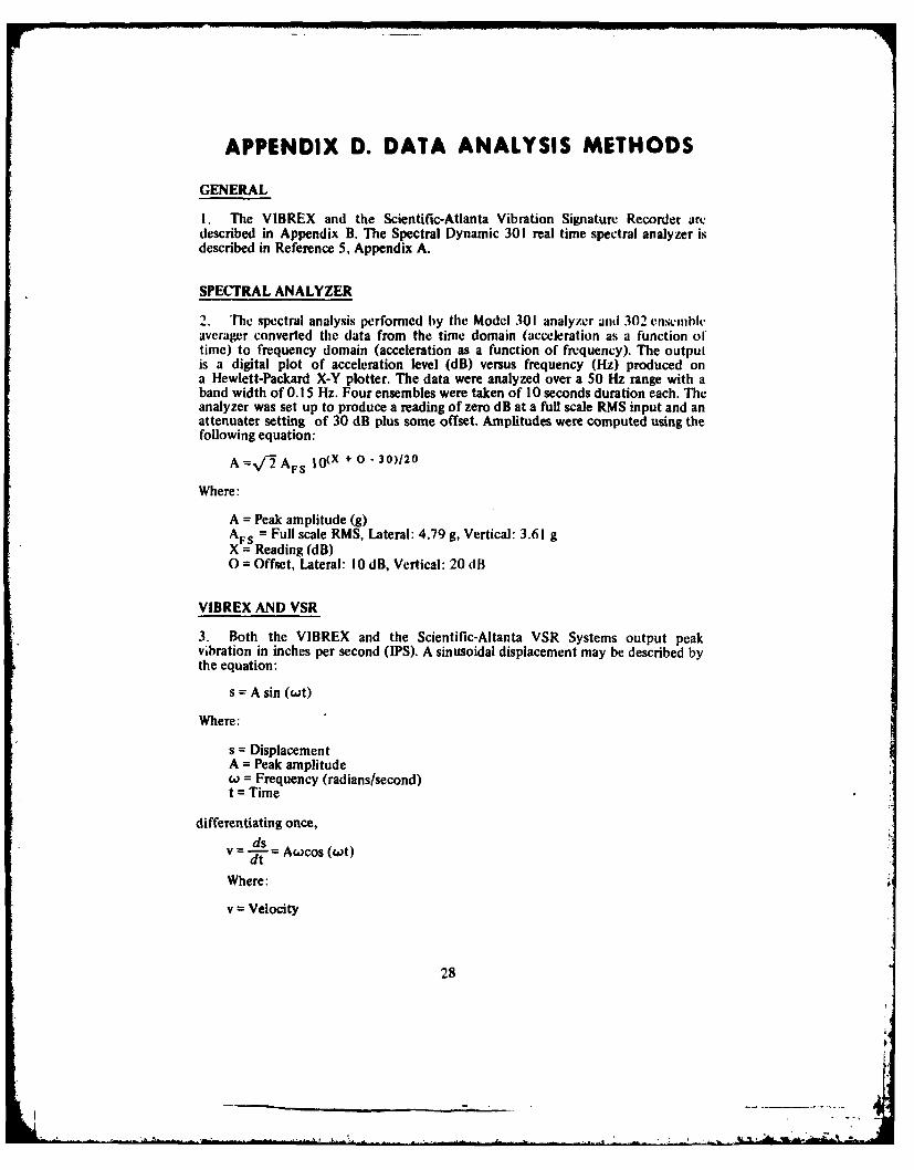
I. The VIBREX and the Scientific-Atlanta Vibration Signature Recorder aredescribed in Appendix B. The Spectral Dynamic 301 real time spectral analyzer isdescribed in Reference 5, Appendix A.
SPECTRAL ANALYZER
2. The spectral analysis performed by the Model 301 analyzer and 302 enscillbleaverager converted the data from the time domain (acceleration as a function oftime) to frequency domain (acceleration as a function of frequency). The outpulis a digital plot of acceleration level (dB) versus frequency (Hz) produced ona Hewlett-Packard X-Y plotter. The data were analyzed over a 50 Hz range with aband width of 0.15 Hz. Four ensembles were taken of 10 seconds duration each. Theanalyzer was set up to produce a reading of zero dB at a full scale RMS input and anattenuater setting of 30 dB plus some offset. Amplitudes were computed using thefollowing equation:
A =/ 2 AFS I O(X + 0 - 30)120
Where:
A = Peak amplitude (g)AFS = Full scale RMS, Lateral: 4.79 g, Vertical: 3.61 gX = Reading (dB)0 = Offset, Lateral: 10 dB, Vertical: 20 dB
VIBREX AND VSR
3. Both the VIBREX and the Scientific-Altanta VSR Systems output peakvibration in inches per second (IPS). A sinusoidal displacement may be described bythe equation:
s = A sin (wt)
Where:
s = DisplacementA = Peak amplitudew = Frequency (radians/second)t = Time
differentiating once,= dsv = Awocos (wt)
Where:
v = Velocity
28

differentiating again,
av =-Aw2 sin(Lwt)
Where: d
a = Acceleration
disregarding phase,
a = v
Since desireable units are gs, IPS, and RPM respectively, the equation with unitsconversion is:
a =0.0002713 vw
29

APPENDIX E. TEST DATA
INDEXFigure
Figure Number
Ice Phobis Test Baseline IIce Phobics Applied 2Ice Phobics In Dirt 3Blade Tracking Test Baseline 4Pitch Link Lengthened I Flat 5Pitch Link Lengthened 2 Flats 6Pitch Link Shortened I Flat 7Pitch Link Shortened I Flat 8Pitch Link Lengthened 3/4 Flat 9Baseline Condition t0Tab Bent I Deg Up I ITab Bent 2 Deg Up 12Tab Bent 1 Deg Down 13Baseline Condition 14
30
FIGUJRE IR
IRRA- -FR zm ,.
II
tL~jii~ I t4~1L4
4-
-7th
L 4L --I1
-1 -
-- P AlOT
FLT 48 LOT 3

F IGUARE 189
1-
_T 019 I -4
-77
t
i--- IVF
4b Ad It_ TL
__ I *-~)~ I.32MT 400 VW

FIGURE 2R
- 4-
I T
I __ I
_ .4 4 _ . 1 __ . ...
2-- --H- -- -
-JL 1 * IF- - -4-
E_ IT -j- ,T Go m ,--!"-
I
. ...p p-p- ---I ,-- -- L -- + --_. . ..._ ...
I 4
--... -V' --- v-' . - 7 . -' -- -:-- -- - - - . - -- - . . ., -r-p- - - - ... .. . . - - 4 - . . . . . .
T - I.. ;A. I I . L-,
L :.1 h tI. , [ ... : _ .
T 4414{-T1.4 •I I J
33FLT 47 LAT

FIGURE 28
I + 4
I Ai
Tt.t.0
4 Ll
___i F--t I r fl
t :71 1 5
Z,: -i 4
4-1~41
Ab I_ L ~i ts)
- -- ~ -- ~ - j--34
FIL 47 MT __
IWilli

FIGURE 3A
A T 1 1 -s a F l. 0 F1map- rp
/~~~~~~~~~ t J 1 r_.Ii J; ,) mm..
1 -- 4-- 4-4--
IL4I7 -v44
I4K I - ~~-j --
FLT 48 -I' --T
; i ', I l. , , U!:i..''Il , K z l I1' zl '4t1€l lnl-1 .I-vI
/ i I I t -K' .Ie).. -T -s),,t u -±- -i ... .I"i s~~~i.I: .
-L ,- -:!- lll:il.t :.-1- i i1 :, .J .K H .. .-K - 1-- ' -+-- : . ....
. ... | t K I .. .II .. . .r1
- 7 -I-- -' _ . ' f , . . . . --[ •m ~ ... , t:. " . . .. .. .. . . .. .
,.+ _I I I I I I 2-i t : i I
._LLJL_. ~ ~ ~ ~I .,,i -.- I- , .t.,.- ., t I, .1 .-. :1 t. .. !:t 1" i izj , ..
... _. L, _ L~ I: .!i W.i- L _ _: £, t .1 1 : '
I ) I " i ... .i" " * :: " . , - " ' i- . . . - I - .: "
... . , k ,, ) :: .. >;.: 1 .,. , , t , l= l8. _o_.._I._ __I_, 1_ _ _ __t
ri: JwLL n iffiLnLLLLn LLLL w Kf--;, n ht" t7K......
' ) ~i =, " • - - 35 P' .' '.'"LLL ' I-L
.... 483 L i . .J 1 . L x ! IIl1 1:Ia l H I I:,

F IG4RE 3B
jV~ ~~~ -R<; ~LST 7
fl'1~L iFni if to
I L
L LL i I ti-1-~4 -B!?IHr~
144
T_-1t
L 7
-~4 -
36
nr 400 VWT

FIGURE 4A
N MI- 1 * "lot,
Wo I _
ii---
I 4e)
44
-V 4-1--
L 1-4 T-
L 6 4 4 -T
~ T~mt tn-I>I zii±7____ 49IA

FIGURE 45
1-4-4~
-t-t-- _ _t ~
I L
I '4-4-
. L-- i-~
MT_ 4 "MI

FIGURE SA
VTTT --v-- - C
-- 4-
r! -7
T, -- K -- ...
7 I-T i-7T
7:. -7 . .L
*4 r~ j: I 1. t
- AT
39
FLT 61 LfiT

_-r- 7- VTR
-1771aimi
.44
.1.1
K ~ ~ -1
- - l f rK41-.64T ,-
0R i fto 7jtI re)
#40
4 OLT 61

FIGUJRE SA
vij~ ISTI
.417 -T- 'K17-14 ' I.- .- t-tI
- T- w. i!r - ~
t d
.117
14
TFl- 1H 7--t- V --
41v
.................................... StLi

---.4- L tOIL4 +
Fo t -4-A
~:z~'-7 ---- T:IE:~.6:iI q. ;It
I 1
t P!
~4--i-
77 ff
WI ~ 42
FLT St YVRT

F I G'E 7-1ST 4-
~~12+}E~277~ ... .rj ...- F~4mo on--
...... ... .....
I - li
L. L
1<~J *'F_
~~'t'~~'f~~ IMAM _ ~ ~ HrTh ~ ~ il-i_ _ _ 43 l& I r4
M1TV .13 LOT~I57~

I te CL ~
cli I
I I..
0 7:
I A. L
44FLTvz~ 53 TMj

VI ~F IGUARE OR TSTTC
If MOM
1 3 IJ1
paT t
FF{~-4- 1 4-l
j-~-4
-2 -b IW KH- do
IMT BM LSAI -

FIGURE 88
t LMtI -
7F.F
1 .T+; w +.: --T
-T 7 j-v
k1 Lt,41- 4 t Ik.
46
FLT so6 vwR

FIGURE 9A
P't f
aI ll .
....I-1 ]---]-]- -- r!- i mil a . f l INS ;-- + ~ [I ~ - -I - -i T --
- H ; i _J t __ _ ii.....- -- -H
_ 4 ; .t ~ ~ t, i ! j I -. . v u i r; , I I t-- -+i JiT: i i I
I-1 -
- n m i T 1SI ! 1 ' - - - -11 _/ ,-! -/ ] ,-
/-+1 : l ' / I- t I ', F 1 ! I ! tI ! , l 'IL:_ ,t ,1 ,, .. ,;'fN , , .
, .i I.i tI i i ' . '
'447
i L T . , . _ .
V t-', .-- - --• 1+-K -- ii--- ,--r--T i t
l- ..... t ... --*2 -++-L ; ....... I_ -. -- - 4 I- .. .. .a_, .... {-i- + -I- -. ._L _, . ..
/ / t i - I , 1 - I " I . I i ,
-- . , . t , , 4 i: 1-- r - - -I--
! .I -L ._ . _- I 1 1.... ._+ _, _, = _ _+ __ + _ ._+, _ + _ _ ,L .. . -- -- . ,d -+ --- :- l- ,- :F d -. ,--47 '
7LT 64 LAT . ' ' : f ' '' ;; ! '
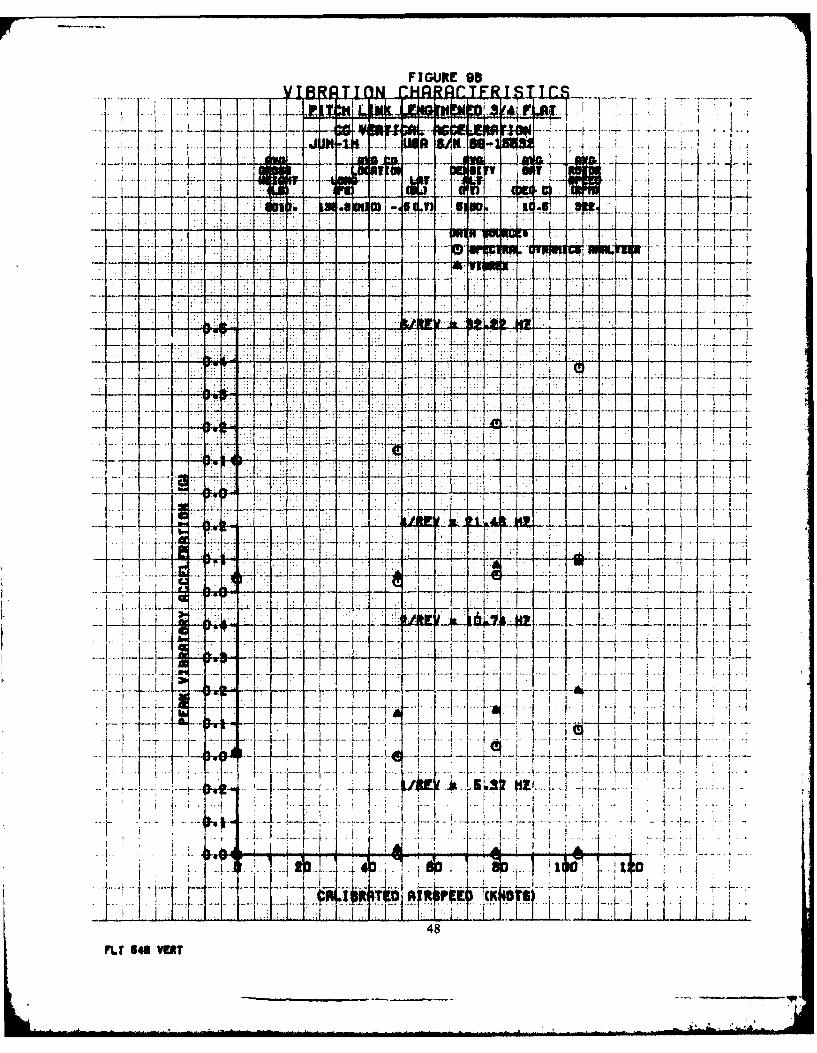
FIGURE 9B
4471$. 14.
-K tt19 I
e -k 14
t~r-1~*-A -51
1~0 JKIL ___
~~12~14~ 4 -48FLTI, 54itM

F IGURE IODA
T-- To
4- 4-4--t 4 A4 -
7120 + Yi-777I 1 LfT 1 I
FL NJ LINT~! 4-

1777C77'i ~~17
* -* L+1 EL2-a -0
----- - ----------

FIGURE hAf
IT I-T - m s S A LI-
T el
I 1 4
FLT~L W I 'I .
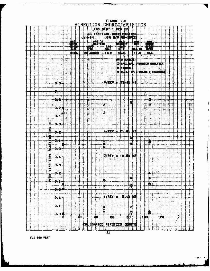
FIGURE 11B
I ~ ~ ~ ~ ~ ~ ~ q I m kR~ t- '
.... ~ ...
F i-
7-- ol r No
.~ ..... .. ..
..... .... .... .FA777 W,
:1± HV -IL
I A 1-
52FLY BOA VERY

FI GURE 12A
J --
V4 +
i-i7--
,---,_,,-1 -
g- J--_
1Ki i-L"
...... 71F:. ...
-r---V -t---.-,--t
-
....
~ -t-4.
I{7 4i*+ .---.-.-- -
-4- i i 'H ,
4HI53 I
MT M LO

-1 I
.7.
* 7 FA
1rVFIfFI .f7+ .K ..
r7r+ 7 l.
* ~~ . ; :
Hi S-p..-
-r7~ ~~~*
41 . lI
T.77 cII 1rL4..T .Ii~if~* 1
-
15i
54
F IGURE 130
I~ cs.- i
- Ir
-4-
I 1'--4
n4m amoI.3z±~IiI~ t~ --- L
~5
FM1 a" K - --A---- - .

F IGURE 138
I--- -7f . -
I I v -A
lii
ill 77- t
~xzL:
t'j
-l-p
.4.4
r -i-
1'T
FLT~~ ~~~ On
tU
6Ii:,

I L
r7
-.. -
r4--~ --TB 71
-- -7
I L UFLTU a S

FIGURE 140
*-1.VTR R~~T7 TTY' S TT
WIL
F --T-7I I
tot
K ... i I.: I l a
- ±-F7---
f ? .I I .
'L1.L_ " ,H- tl ?
a,
58IN MY

DISTRIBUTION LIST
Deputy Chief of Staff for Logistics (DALO-SMM) I
Deputy Chief of Staff for Operations (DAMO-RQ) I
Deputy Chief of Staff for Personnel (DAPE-HRS)I
Deputy Chief or Staff for Research Developmnent and Acquisition
(I)AMA-PPM-T, l)AMA-RA, DAMA-WSA) 3
C'omuptroller ol the Army (DACA-EA) I
US Army Materiel Development and Readiness Command
(DRCDE-DH, DRCQA-E, DRCRE-I, DRCDE-RT) 4
US Army Training and Doc' nne Command (ATTG-U, ATCD-T,
ATCD-ET, ATCD-B3) 4
US Army Aviation Research and Development Command
(DRDAV-DI, DRDAV-EE, DRDAV-EG) to
US Army Test and Evaluation Command (DRSTS-C T. DRSTS-AD) 2
US Army Troop Support and Aviation Materiel Readiness Command
(DRSTS-Q)I
US Army Logistics Evaluation Agency (DALO-LED I
US Army Materiel Systems Analysis Agency (DRXSY-R, DRXSY-MP) 2
US Army Operational Test and Evaluation Agency (CSTE-POD)I
US Army Armaton Center (ATZQCD-T, ATZQ-TMA TOTSM-S) 3
US Army Combined Arms Center (ATZLCA-DM) I
US Army Infantry Center (ATSH-TSM-BH)I
US Army Safety Center (IGAR-TA, IGAR-Library) 2
US Army Research and Technology Laboratories/Applied Technology
Laboratory (DAVDL-ATL-D, DAVDL-Library) 2
US Army Research and Technology Laboratories/Aeromechanics
Laboratory (DAVDL-AL-D)I

US Army Research and Technology Laboratoies/pTopuI~ofl
Lbboratory (DAVDL-PIrD)
Defense Technical information Center (DDR) 12