U.S.A. - World Radio History
66
vOCTOBER, 1954 1 VIDEO SPEED SERU ICIIIG SVSTEI115 2. TU FIELD SERVICE DATA SHEETS 3. COMPLETE TV SERVICE INFORI11ATIoN SHEETS . _ -, ' e Pro essiana . a+ io_ Thnan, Magazine s ectiin Ev Radio: . erv'j Firm Owner in the U.S.A. . . i ... www.americanradiohistory.com
Transcript of U.S.A. - World Radio History

vOCTOBER, 1954
1 VIDEO SPEED SERU ICIIIG SVSTEI115
2. TU FIELD SERVICE DATA SHEETS
3. COMPLETE TV SERVICE INFORI11ATIoN SHEETS
. _ -,
' e Pro essiana . a+ io_ Thnan, Magazine s
ectiin Ev Radio: . erv'j Firm Owner in the U.S.A. . . i ...
www.americanradiohistory.com

Lynx' Ra.tqPh,
£darfIecfor
VHF UHF COMBIN
E SNYDER MFG. CO., PHILADELPHIA 40, U.S.A. BELLEVUE TUBE MILL, INC., PHILADELPHIA SNYDER ANTENN-GINEERS LTD., TORONTO 14, CANADA WORLD EXPORT: ROBURN AGENCIES, INC., N.Y.
www.americanradiohistory.com

EDITORIAL STAFF
Publisher SANFORD R. COWAN
Editor SAMUEL L. MARSHALL
Editorial Production ROBERT CAMPBELL
Contributing Editors
LEONARD LIEBERMAN
ROBERT T. DARGAN
PAUL GOLDBERG MARVIN KLEIN
SAN D'ARCY
BUSINESS STAFF
Advertising Director SANFORD L. CAHN
Advertising Manager HARRY N. REIZES
Advertising Sales
LAWRENCE STEINER
Production Manager DAVID SALTMAN
Circulation Manager HAROLD WEISNER
Asst Circ. Mgr. C. J. BINDERMAN
Every Service Firm Owner in the U.S.A.
Receives SERVICE DEALER Monthly
DISTRIBUTION THIS ISSUE OVER 65,000
VOL. 15, NO. 10 OCTOBER, 1954
Servicing Vertical Instability, by Steve Travis 10 The technique of pinpointing causes of vertical instability that originate in pre -oscillator stages.
Block Diagram Analysis of Color Transmission and Reception, Part 2, by Bob Dorgan and Sam Marshall 14
Comprehensive mathematical analysis of the composition and formation of luminance and color -difference signals, simplified by block diagrams.
22
FEATURE ARTICLES
Community Antenna System, by Edward M. Noll The development of an efficient community service by wise investors and
a skilled engineering staff.
Key Test Po'nts, by Steve Travis Systematized troubleshooting of TV deflection, vertical and horizontal os-
cillator systems.
RC Circuits, Part 5, by Cyrus Glickstein Functional characteristics of Complex RC circuits ments, and their application to TV sync circuits.
Sync Amplifier Problems, by Paul Goldberg (A The use of an oscilloscope in conjunction with man
in correcting three sync amplifier problems.
TV Service Information Sheets Complete data on CBS -Columbia Models 17M06,
750-3, 751-3.
with series -parallel ele -
28
30
Workbench Feature) 34 ufacturer's service data
65-72 22C06, 22C38, Chassis
CIRCUIT AND SERVICE FORUM
Answer Man CBS -Columbia Ch. 750-3-Height Shrinks 27
Increasing Scope Gain 52
The Workbench-Sync Amplifier Problems RCA KCS82-Horizontal Pull 34
Emerson Chassis 120162A-Horizontal Pull and Vertical Roll 34
Motorola TSI14-Intermittent Horizontal Pulling and Vertical Jitter 35
Rider TV Field Manual Service Data Sheets Firestone Models 13-G-128, -129, -130, etc., Codes 334-3-MS39A, 334-3-MS39B 37
Pacific Mercury Ch. 200-I, 2, 3, 4, etc. 39
Western Auto Model 2D-13I5A, 2D1325A, etc., Ch. 2ITIA, 17TIB, 21T2A 41
Video Speed Servicing Systems Philco Chassis R181, DI81 43
Zenith Chassis 21L21 45
DuMont Chassis RA306/307 47
BRANCH OFFICES DEPARTMENTS
LOS ANGELES Editorial 5 New Products 50 TED E. SCHELL Association News 18 Trade Flashes 54
2700 West Third Street Answer Man 27 Trade Literature 58 Dunkirk 2-4889 Workbench 34 Advertising Index 64
CLEVELAND
RICHAF.D E. CLEARY Commercial Bonk Bldg.
Berea, Ohio BEea 4-7719
RADIO -TELEVISION SERVICE DEALER is published monthly by Cowan Pub. Corp., 67
West 44th St, New York 36. N. Y. Subscription price: $1 for 2 year« in the United States, &
U.S. Poss. Elsewhere $1 per year additional. Single Copies 25e. Reentered R9 second class matter Sept. 25, 1950 at the Post Office at New York, N. Y. under the Act of Mar. 3, 1879. Copyright 1954, Cowan Publishing Corp.
POSTMASTER: SEND FORM 3579 TO RADIO -TELEVISION SERVICE DEALER, 67 WEST 44th ST., NEW YORK 36, N. Y.
RADIO-TELE`IISION SERVICE DEALER OCTOBER, 1954 I
www.americanradiohistory.com

the
1 1
the most important antenna development since the
introduction of the basic Yagi
The World's First
Triple -Powered Yagi .. .
Brilliant all -channel
VHF performance - and really ready for
No other antenna provides such outstanding
long distance reception in black and white.
e No other antenna is so well prepared to meet
the exactas requirements of color television:
Uniform high gain, fla4 frequency response,
extremely narrow polar patterns, highest
front -to -back ratios.
Stacked
SUPER RAINBOW
model no. 331-2
Single hay
SUPER RAINBOW
model no. 331
www.americanradiohistory.com

these 3 basic engineering advances
make the RAINBOW the most powerful all -channel VHF antenna
science has yet produced.
1. New spacing formula: Channel Master research has
now established new, more efficient relationships between the Yogi's parasitic elements (directors and reflectors) - far greater efficiency than a screen.
The radical new spacing arrangement between these elements
has, for the first time, extended the cull efficiency and high gein of the basic narrow band Yogi over the
full width of an entire VHF bond.
2. New 'triple power" High Band directors and reflector: Three -segment directors and reflectors,
with each segment insulated from its ad'pacent segment,
provide the combined power of three High Band Yogis,
operating side by side, in perfect phase. This is the first time
an enti -e antenna has been made to operate on the same
high gain principle as the fabulous Tr° -Pole.
3. New "intermix" design: Combines - into one single
antenna - two separate , independent sets of directors and reflectors, one for High Band, one for Low Band.
Eacn parasitic system operates only on its own band. No compromise design. N=J interaction. No signal loss.
PLUS Channel Master's original, super -gain TRI -POLE .. .
the unique triple -powered dipole that made the Champion the most wanted antenna in America.
2 great models available: RAINBOW, Model No. 330- for secondary and near -fringe areas.
SUPER RAINBOW, Model No. 331 - for fringe aid super -fringe .reas.
Full band width - highest gain - of any all -channel antenna.
Diagram illustrates independent operation of the RAINBOW's High Band and Low Band pa-asitic ele- ments. Note unique new spacing arrangement between elements.
Heavier lines indicate elements operating an:
Low Band only High Band only
"1 ICI I li I I
III II
T-Tripola (:hewing cur ent distribution)
Note that each High Band element is actually three separate elements,
each insulated from the others, for triple -powered performance.
Here! how the FAINBOW out -performs the famous Champi.
Gain Over
1 -Bay
Champion
Gain Over
Stacked í4 Champion
CHANNEL
1 Bay RANBCUrr
14ey Sr Pia
!ANBCW
CHAUNEI
Stacked RAlIBCrW
Str cke d
SUPER
RA NBOW
O
DB
+1
DB
+1.5 DB
0 DB
+1 DB
2
DB
0 DB
-1.5 DB
+1.5 DB
+' +2 BB DB
+2.5 -3.5 DB D8
+t.5 +2 )B DB
+2 ,+2.5-3 +3 +4
DB DB DB )B DB
+3 +2i DB CE
+3.5 +E
DB GE
9 10 11 12 1C
+1 +.5 + 5 +1.5 +2.5 DB DB D3 DB DB
+2 +1.5 1-2 +3.5 +4.i DB DB DB DB DB
9 10 '1 12 11
+,5 +.5 +0 DB BB DB
+.5 DB Olt
+1
DB
+0 DE.
+2 DE
+0 DB
+1 DB
+2.5 DB
+1.5
DE
+3.5 DE
H,rir.nt.l Potar
oafern 'relatire .oltaçel
c
:0
co
o
Stacked
RAINBOW
model no. 330-2
Single bay
RAINBOW
model no. 330
CUM MASTER CORP. FL[FN"WLEE, N. 1.
THE T9RLDS tARTEs1 MANUFACTURER OF T! ANTENNAS
www.americanradiohistory.com

HVO-13
WATCH
H VO -16
MERIT-the only transformer line designed exclusively for service- will be on the spot with exact replacements for color television.
Since 1947 Merit has made available to you a complete line of replacement transformers including such exact replacement requirements as Merit Model HVO-13
for Sylvania, Model HVO-16 for Philco and Model HVO-23 for Admiral.
Merit's three plants are geared to supply your replacement transformer needs
when you need them wherever you are.
Ask your jobber, or write for, your copy of Merit 1955 Replacement Guide #407 listing up-to-date replacement components for all models and chassis of TV receivers.
FOR EXACT REPLACEMENT IN
COLOR TV AS IT HAS BEEN IN BLACK & WHITE TV SINCE 1947
MERIT COIL & TRANSFORMER CORP. 4427 N. Clark Street, Chicago 40, Illinois
www.americanradiohistory.com
EUl'l'01It11....
A Publisher Hurts Servicemen
In yesteryear it was common practice and con- sidered good business for competing publications, particularly newspapers, to blast away at one another at the slightest excuse. Of late this practice has not been indulged in because modern publish- ers are supposed to be more polite than their fore- bears. Well-because we are both old fashioned and because we have the interests and welfare of the radio -TV servicing profession at heart, we now find it necessary to blast away, with all the power we command, at a contemporary publishing firm whom we sincerely believe is doing professional radio -TV servicemen a rank inexcusable injustice. We refer to Ziff -Davis Pub. Co. (who for years has published "Radio News"-which is supposed to be published for the benefit of radio -TV service- men) . Ziff -Davis has just launched another month- ly magazine titled "Popular Electronics" Both "Popular Electronics" and "Radio News" have the same Editor, a fine fellow personally, by name of Oliver (011ie) Read.
Scanning "Popular Electronics" first issue we find in it articles titled: "How To Test and Replace Radio & Television Controls"-"How To Align Re- ceivers"-"How To Fix Home Radios"-"Adjusting Your TV Height Control"-and others of passing interest.
As "Popular Electronics" like "Radio News" is sold on newsstands, copies can get into the hands of laymen, set owners and others besides profes- sional servicemen. These laymen, then, are being advised and told how to do their own radio -TV re- pair jobs-jobs that, under normal circumstances, without "Popular Electronics" interference, might be relegated to professional servicemen.
Isn't this a ludicrous and intolerable situation? Here we find that a magazine publisher who claims to be the serviceman's friend is actually taking jobs away from those servicemen, worsening their al- ready too -competitive position. Ziff -Davis, in this age of free and unrestricted enterprise, has, by launching "Popular Electronics" with its "service - your -own -set" type of articles, bitten the hands that feed them. The companion magazine "Radio News" with the same Editor as "Popular Electron- ics" will probably find itself loved much less hence- forth by professional servicemen who naturally do not want their income or profession undermined.
by S. R. COWAN PUBLISHER
Our Prediction Is Upheld
Just five years ago RCA introduced the first 45
rpm record. We then predicted that "45's" along with 33 1/3 rpm recordings, would revitalize the phonograph business and eventually force 78 rpm records into obsolescence. That prediction is being borne out. In 1949 record industry sales totalled 160 million dollars. This year the total may exceed 225 million. And this despite the tremendous im- pact and competition of TV, which was in its infancy in 1949. Think of it! In the past five years 200 million "45" records and 13 million "45" turn- tables have been sold. Think of all the needles and cartridges that can be sold in the years ahead!
Mr. Frank Folsom, President of RCA, is now of
the opinion that in another five years the "45" will account for more than 75% of the total record volume. We don't care about that-but we do hope that with each coming year more and more elec- tronically actuated phonograph record players will be sold and used. They can be and are a wonderful influence upon the nation's adolescents who in time may be taught to appreciate good music and truer fidelity of phono reproduction.
In this connection may we voice our objection to the rampant and frequently misused term "High Fidelity." When the writer founded and became the first publisher of the magazine "Audio Engi- neering" in 1944 it was his thought, and that of his associates, that the term "High Fidelity" meant truly faithful wide frequency -range reproduction of the better class music or artistic rendition. To-
day some manufacturers put one or two tiny speak- ers, each having a 300 to 3000 cps range, into an oblong cabinet and call that sort of garbage "Hi- Fi." Something in the way of standards is needed to differentiate between genuine and quasi High Fidelity. Possibly the Audio Engineering Society and the Institute of Radio Engineers could get together on a standards project of that kind.
Being close to the matter, we realize that for various reasons, some valid, others selfish, many manufacturers would not wish to have such "stand- ards" established. This group might stymie any action that IRE or AES might undertake. At least, an attempt to define High Fidelity minimums should be made, otherwise many avoidable mis- understandings between the public and the sellers of audio reproducers are bound to arise.
RADIO -TELEVISION SERVICE DEALER OCTOBER, 1954 5
www.americanradiohistory.com

ACHIEVEMENT OF A
For those who pursue the ultimate-the rediscovery of perspective in music...
Imperidd
PR -100 The stimulat'on and pleasure gained by listening to a live per- formance is the result of much more than frequency range con- siderations.
Here is a revolution-the use of true proportions of sound in authentic reproduction including smooth coverage of the complete useful frequency range and thus recreating the fine performance with the greatest possible degree of accuracy.
Voices come to life and there's a new almost geometrical separation of instruments. A three-way system with 1-f unit loaded by a new -design reactance-annuling trilateral -mouth horn for bass; selected compression -driver horn -loaded mid channel with intrarange equalizer for a final touch to precise balance and coloration elimination; and superlatively smooth, space -blended supertweeter top. Each instrument is indi- vidually serial numbered and accompanied with a signed certificate certifying that the reproducer fully meets the ex- acting performance standards set for it. (Components and performance are the same as for RS -100 Laboratory Reference Standard Reproducer.)
PR -100 "IMPERIAL" REPRODUCER
ST -919. Selected Mahogany. Net Price $525.00 ST -918. Satin Korina. Net Price 535.00
LABORATORY STANDARD
RS -100 Built for research comparison
The Imperial was designed by the Jensen engineering staff for their own use as a reference standard of the highest quality of high-fidelity reproduction. In this original laboratory version the RS -100 Laboratory Ref- erence Standard Reproducer is a new and important tool for sound, recording and broadcast engineers, workers in psy- choacoustics and music critics who require an unusually high quality of reproduction. Some music lovers and audio- philes will undoubtedly want to own an RS -100. Cabinet is plywood attractively two -toned in blue gray.
RS -100 LABORATORY REFERENCE STANDARD REPRODUCER
ST -920. Net Price $468.00
ell MANUFACTURING COMPANY Division of the Muter Co. 6601 S. Laramie, Chicago 38, Illinois
engen Jensen-world's quality standard for more than a quarter century.
www.americanradiohistory.com

VA NEW CONCEPT - IN ROTATOR ENGINEERING! Built -In Thrust Bearing -3200:1 Reduction Gear Train-Dynamic Braking!
PIANO KEYBOARD TUNING! Finger-tip control tuning. Precise
antenna position indicated at all times.
Magnificently styled console is
a joy to behold.
Especially designed for fidelity reception of sharply directional
color transmission. The JFD Roto King is the first ever engineered to
overcome shortcomings of conventional rotator design which seriously
affect the accuracy of antenna pcsition and indication:
ambiguity (error) and voltage fluctuation. The result is
stop -watch tuning of antenna for fidelity reception of critically
'%1 directional VHF, UHF and color signals especially.
CARTRIDGE SERVICING! STOP WATCH TUNING ACCURACY!
Detachable power drive unit ran be
removed it seconds. No laborious
dismnntlirg of ..atenna.
UI ra-sensitive control ysten accurate
within IA degree of des red position.
Instant stop. No ambigiity. No drift or error.i
390 DEGREE ROTATION IN EITHER DIRECTION
Complete 390 degree revolution permits
station selection beyond end of
normal 360 degree traverse.
JFD MANUFACTURING CO., INC., BROOKLYN 4, NEW YORK
LOOK TO JFD FOR ENGINEERING LEADERSHIP
Export Division: 15 Moore St., N.Y.C.
WRITE FOR FORM NO. 288 Model RTIOO-M Mahogany S44.95 List Model RTIOO-iV Ivory 44.95 List
www.americanradiohistory.com

ANOTHER RAYTHEON FIRST!
,
N NEW 17" 90° DEFLECTION
PICTURE TUBE
17AVP4 15 5/8"z3/6
f 9 1/8"± 3/16"
Raytheon leads the way to smaller, light weight, more compact, tele- vision receivers with the amazing new 17AVP4 monochrome picture tube. It is 3% inches shorter in overall length and approximately 4 pounds lighter than present 17 inch tubes. The type 17AVP4 incor- porates a new 90° deflection angle bulb, a 1 inch shorter neck length and achieves maximum compactness with conventional viewing area. The 17AVP4 has electrostatic focus, magnetic deflection and features the same crisp, clean picture that makes all Raytheon Picture Tubes outstanding for quality.
This important new Raytheon tube, developed and produced at Raytheon's new modern picture tube plant at Quincy, Massachusetts is one more reason why you can standardize on Raytheon Picture Tubes with complete confidence that you are giving your customers the very latest and best.
Remember, Raytheon Picture Tubes are Right for Sight, Right for You. and always Neu'. Buy tlzenz through your nearest Raytheon Tube Distributor.
RAYT ON MANUFACTURING COMPANY
b 1/2"t3/16"1
19 1/4".±3/8"
RAYTHEON
excel Newton, Mass., Chicago, III., Atlanta, Ga., Los Angeles, Calif. -el. .Ammifilk
!COPING AND PICTURE TUBES RELIABLE SUBMINIATURE ANO MINIATURE TUBES SEMICONDUCTOR B11101191111 BES
1. es
8 RADIO -TELEVISION SERVICE DEALER OCTOBER, 1954
www.americanradiohistory.com

a2,9 LABORATORY PERFORMANCE
PRICED
FOR THE
SERVICEMAN
i89° For Black and
White and Color
Television ... plus FM and AM
Radio...
, xne.el.,Irheousrv Co {Nt.
' = t.t.61"W1,1e -=
D 2e.269M6 DI 410 -49K Dt e49.60eM6
RAND to
-16 tot
MUC
etae,zweic SWEEP GENERATOR
,, %
TUNING Mc
r".3730 3D D, r[
D2 !_
30 DB 2028 tOD8 SDI 308
DO-ALL U.tM Qie ON,' ste
so
TUNING
beöth 'I .
II 41 1111J , i2,.[6 ATTENUATOR
Unexcelled in performance and versatility, the 2CP model 780
is engineered as a completely electronic sweep circuit with- out motor or moving parts. Unique electronic unidirectional coupling provides for sweep in one direction only at o
uniform output level (AGC). For use with ary marker gen-
erator and oscilloscope, model 780 is the first
laboratory type all electronic sweep generator priced
reasonably enough for service use.
Service Designed for Ease of Operation: Built-in Detector/Comparitpr Permits
(1) Visual observation and accurate settings of marker signals and sweep width of aliçnment of TV IF's and Wcve Traps.
(2) Laboratory and service technicians to check their test equipment. Check of test set-up or long leads.
Push button attenuator for rapid, precise alignment and measurements. Automatic internal blanking with straight line base genera- tion for scope picture-eliminates retLrn trace.
180° 60 cycle phasing voltage for use on all oscilloscopes available on front panel. Jack provided for modulation by external signal such as
color generators (bar or dot) and is automatically mixed in
the sweep circuit.
(3)
20
RCP Features: Anti -backlash dial-Elec- tronically regulated power supply-Highly linear sweep to close tol-
erances of manufacturer's specifications-Range 3.2 megacycles to 800
megacycles-Wide sweep
width control 0 to 30 megacycles-Automatic gain control-Precision, triple shielded attenuator.
SPECIFICATIONS Sweep Linearity: Exceptional high degree of linearity not possibly
obtainable in mechanical sweep..
Linearity Sweep Linearity Sweep Band Width Within 2 DB Width Within 4 DB
A 0- 8 me Max. 15 me
B 0.10 me Max. 25 me
C 0-10 me Max. 22 me
D 0- 8 me (k) 70 me Max. 25 me
0- 20 me a 200 me Max. 30 me for improper grounding
RADIO CITY PRODUCTS CO. EASTON, PENNSYLVANIA
RADIO -TELEVISION SERVICE DEALER OCTOBER, 1954
www.americanradiohistory.com

g9Lvi&Lng
ONE of the compensations of tele- vision servicing is that the symptom
shown in the picture tube most often reveals the defective circuit. However this premise may be a faulty one if fol- lowed blindly. This is particularly true in the case of vertical instability which generally takes on the following forms:
1-Picture locks but is very toudhy 2-Picture locks but is out of frame 3-Vertical jitter 4-Any of the above plus excessive
contrast It is very tempting to interpret the
above symptoms as being caused by a defect in the vertical oscillator circuit. However, it will be generally found that most vertical sync troubles do not orig- inate in the vertical oscillator circuit proper, but rather in the many circuits that precede the oscillator.
Sync Compression The most common cause of vertical
instability is sync compression which may be better understood from the fol- lowing discussion. When the composite video signal is formed at the transmitter, the sync pulses occupy 25% of the upper portion of the signal as shown in Fig. 1.
When the composite video signal is reproduced at the receiver it must be a complete duplicate, in every way, of the signal formed at the transmitter. In certain types of troubles that may occur in the receiver, the amplitude of the
VERTICAL
INSTABILITY
100%
75%
50%
25%
0
1t_
Fig. I - Normal signal
sync pulse will be reduced while the video signal amplitude will remain con- stant or may even become greater. A reduced sync pulse is shown in Fig. 2. From this figure it can be seen that the video signal now occupies 90% of the amplitude and the sync only 10%. The lowered sync level is referred to as sync compression.
by I Steve Travis
100%
75%
50%
25%
0
jj"grim.i* I
Fig. 2 - Sync. compressed.
Sync compression can occur in any stage through which the composite video signal passes. This includes the:
1-RF stage 2-IF stage 3-Video detector 4-Video amplifier Sync compression in these stages may
he caused by any of the following:
R.E.
AMP. CONV.
OSC.
1ST.
VIDEO
I.F.
2 ND.
VIDEO
I.F.
A
3RD.
VIDEO
I.E
4 TN.
VIDEO
I.F.
VIDEO
DEL AND
A.C.C.
RECT.
VIDEO
AMP.
Fig. 3 - Block diagram of sync check at video detector output.
10 RADIO -TELEVISION SERVICE DEALER OCTOBER, 1954
www.americanradiohistory.com

1-Defective tubes 2-Defective agc system 3-Defective components causing
non-linear amplification Except for excessive contrast the same symptoms indicated in the first para- graph may develop from defects in the sync circuits themselves. Although not referred to in the category of sync com- pression we will cover service proced- ures for these conditions as well.
Since the sync pulses affected are both horizontal and vertical it may be asked why sync compression does not generally result in severe horizontal instability. This is because of the stabilizing effect of the horizontal a f c circuit. In most cases, if horizontal instability does oc- cur due to sync compression, it may appear as a horizontal pull.
Service Procedure The prime objective in trouble shoot-
ing is first to isolate the defective stage and then to isolate the defective part within that stage. The first component that should be checked is the tube, and that by substitution only. Care must be taken in this procedure to change all the tubes of the complete section sus- pected. If, for example, more than one if amplifier tube is gassy it may be over- looked in a substitution process in which only one tube at a time is replaced. When the tubes of a particular section have been eliminated as the possible source of trouble, we can then proceed to eliminate other components in the suspected stage.
Key Test Points A key test point for checking sync
operation is the video detector output designated as point A in Figs. 3 and 5. By using an oscilloscope we can observe the composite video signal at this point. If there is no sign of sync compression at this point we may then proceed to
Fig. 4 - (A) Proper and (B) Improper waveforms at video detector output. (B) indicates sync compression in video signal.
check the video amplifier and sync cir- cuits. Proper and improper wave forms are shown in Fig. 4A and B, Fig. 413
indicating compression. The oscillo- scope should be adjusted to show at least two vertical fields. If there is any indi- cation of sync compression shown on the scope then the cause must be lo-
cated somewhere between point A and the rf amplifier.
Faults may be isolated by two meth- ods. If the serviceman owns a crystal detector probe, he should connect it to the vertical input terminals of the oscil- loscope. This now enables him to check the composite video waveform at any point on the if strip. The test procedure is from the last if amplifier back to the rf stage. If the waveform at the plate of any stage shows compression, and the input does not, the stage being checked is defective. A voltage or resistance analysis will most often show up the offending part.
If the equipment mentioned in the previous paragraph is not available a
second method of attack may be em- ployed. This is a straight voltage analy- sis from the last if amplifier to the antenna. When making this voltage analysis special attention should be paid to the control grid readings. The ac- tual value of voltage to be read at the control grid is determined by the strength of the incoming signal and the condition of the agc circuit. Therefore the value of control grid voltage ob-
tained may vary somewhat from pub- lished figures. A rule of the thumb range is between -2 to -6 volts.
Grid Current Voltage is not the only quantity to
be checked. Of equal importance is the absence or presence of grid current. If grid current flows in the rf or if tubes an inevitable result will be sync com-
pression. This can be checked by measuring the output voltage of the agc rectifier at point B in Fig. 5.
This voltage will normally be pro - [Continued on page 611
V7
6BC5 C79
1st. I.E
FROM TUNER
,5K 2
3.3 K
470
V8
6BC5 2nd. I. F.
A.G.C. TO TUNER <
3.3 K
V9 C83 6BC5
3 rd. I.E 470
B+ 3.3 K
470
B+
C93 íC
YV
R67 100 K
R66 27 K
TEST POINT
V10
66C5 4th.I.F.
B+
470
Vil 6AL5
DET.-A.G.C.
120 K
o
TO VIDEO AMP.
Fig. 5 - Typical video detector, agc rectifier and vertical instability distribution circuit.
RADIO -TELEVISION SERVICE DEALER OCTOBER, 1954
www.americanradiohistory.com

HEAR T H E Based on thefamaus University model WLC Theater System used so success- fully and extens vely in deluxe sta- dium and outdoo theater installations ... auditoriums, expositions, concert,, malls and other important applica- tions where only the highest quality equipment is acceptable-University engineers now bring you a smaller, compact version-the BLC-for gen- eral application in public acdress work. The BLC is the New stand- ard for both voice and music, indoors and outdoors. The BLC is now yours, the low low price of
$75 LIST
SPECIFICATIONS
Response 70-15, Power
Capacity 23 wefts Impedance 8 ohm Dispersion 120 degrees Mounting
180° adjustable .1.1" bkt. Dimensions
22 Vs" diameter, 9 ' depth
KM fAEG.EMEAGY
Ask your distributor fora convincing demon ion, and HEAR THE
DIFFERENCE!
DIFFERENCE MAKE giujell P.A.
A HI-FI INSTALLATION
Wir
BA .ANICED"COM- PRESSION"TYPE FOIDEDHOF:N,
starting with eight inch ! hr Dal and energized by top qucl ter I )w f-e- quency "woofer" dris, p-ovides
more lows than other bu ky desig is.
DRIVEBUNIT T\VEElIER with exclusive patented "recip-o- cating flares" wide aegla horn transmits more highs with greater uniformity . . . high frequercy response that you ca i he 2r!
WA` MODEL
BLC FULL RANGE WEATHERPROOF
COAXIAL SPEAKER
DUAL RANGE THEATER TYPE SYS-
TEM permits uncompro- mising design of the
"woofer" and "tweeter" sec- tions for greatest efficiency. Hear
it penetrate noise with remark- able fidelity and intelligibility.
SEPARATE LOW AND HIGH FREQUENCY DRIVER SYSTEMS with
electrical crossover reduces intermodulation and acoustic phase distortions common to other systems which attempt to use two dif- ferent horns on a single diaphragm.
EXCLUSIVE WEATHERPROOF DL AL RANGE COAXIAL DESIGN eliminates wcsted space. Depth of BLC is only 9"; can be mounted anywhere, even flush with wall or ceiling
EXPERIENCED MECHAN- ICAL ENGINEERING AND CAREFUL ELECTRI- CA L DESIGN meet the challenge of diversi- fied application and environmental hazards. Rugged, and conservatively rated-you can rely on the BLC.
LOUDSPEAKERS INC. WHIM
I2 RADIO -TELEVISION SERVICE DEALER OCTOBER Q54
www.americanradiohistory.com

A service record unmatched
in the history of television!
CROSLEY SUPERV e "wee awe eiemi
"No more groping and twisting"
"Entire chassis accessible for service" "By removing the cabinet back, every tube is right in front of one's eyes. No more groping and twisting to relocate tube -socket pins. The separate diagram showing the actual filament wiring makes the search for an open filament a matter of seconds." L.B. Hallberg, Hardware Products Co., Sterling, Ill.
Points wired on ter-
minal strips-easier circuit tracing
"The Crosley Super -V is a service man's dream; the new vertical chassis allows the changing of tubes in a few minutes. When service of a more complicated nature is required, the cabinet can be removed by loosening 6 screws; this leaves the entire chassis accessible for service." Roy R. Thompson, Saginaw Distrib- utors, Inc., Saginaw, Mich.
Bonnet -type cabinet lifts right off-no more chassis tugging
All important parts grouped in one plane -all tubes accessi- ble at rear
Division Iei2 Cincinnati 25, Ohio
Crosley gives you more for your money! RADIO -TELEVISION SERVICE DEALER o OCTOBER, 1954 13
www.americanradiohistory.com

Beek . Diagram, AnaQ,9eia
cif
COLOR íR111151111551011
BOB DARGAN and SAM MARSHALL
and
RECEPTION
From a forthcoming book entitled "Fundamentals of Color Television."
Part 2
AT this point it would be advisable to discuss the luminance signal,
EY in somewhat greater detail. The maximum luminance signal of a tele- vision scene corresponds to the bright- est white area in the field of vision of an observer. The minimum luminance signal corresponds to black.
As indicated in Chapter I, the lum inance signal is made up of definite proportions or percentages of the red, green, and blue signals, these being: EY = .3 ER+.59Ea +.11 EB (II -1) These percentages describe the manner in which the individual colors give rise to the sensation of brightness. Thus, green contributes 59%, to the bright- ness sensation, red 30%, and blue 11%. Mixing these colors in the percentages stated above results in the sensation of colorless light ranging from a bright white to dark gray depending on, how much light is present.
As an example, let us consider the case where a color camera is scanning a peak white scene. According to NTSC specifications equal and max- imum primary color signal values ap- pear at the outputs of the three color camera tubes. For a black and white tube to reproduce this sensation of white, the signals would have to be connected to a signal mixing network, called a "matrix," so that the final color signal outputs are produced in the fol- lowing ratio:
30% red, 59% green, 11% blue.
This is illustrated in Fig. 8A where a maximum white signal produces am- plitude as well as percentage ratios of 30, 59 and 11.
Now, if a darker scene is scanned, such as 50% gray, as in Fig. 8B, the
camera voltage outputs will be reduced in each case to i the original value; but the same ratio of color signals will appear at the output of the matrix, that is:
30% red, 59% green, 11% blue.
100 -
0 ,- 50
S
C
E
N
E
S
C
A N
N
E
D
COLOR SIGNAL PERCENTAGES
IN Y CHANNEL J
59 %
30%
R
E
D
(A)
G
R
E
E
N 11%I
IBLUEL
RAY
sc CA EN NN EE
D
COLOR SIGNAL
PERCENTAGES IN Y CHANNEL
J 59- 30%
E E
E _ D N _)BLUE
(B)
11%
Fig. 8-In (A) 100% white signal scene produces following color signal am- plitudes and percentages in Y channel:
Amplitudes: Red -30, Green -59, Blue -I I. Percentages: Red -30%, Green -59%, Blue -I 1%. In (B) 50% luminance or gray signal produces following color signal am-
plitudes and percentages in Y channel: Amplitudes: Red -15, Green -29.5, Blue -5.05. Percentages: Red -30%, Green -59%, Blue- I I %.
Thus it should be evident that the color signal percentages in a monochrome (white or gray) scene remain constant; what differentiates one monochrome scene from another, that is, white from gray, are the relative amplitudes of
the component colors in both scenes.
14 RADIO -TELEVISION SERVICE DEALER OCTOBER, 1954
www.americanradiohistory.com

R
0
E
U
E
COLOR
CAMERA TUBES
A
T
R
Eh-E,
H&V CIRCUITS
3.58 MC.
OSC.
En Ey
COLOR
SIGNAL ENCODER
Ey
COLOR
SIGNAL
C
0 M
B
N
E
R
TRANSMITTER
S E
P
A
R
A
T
0 R
H & V SYNC
COLOR BURST
COLOR
SIGNAL
H & V
OSC.
COLOR
SIGNAL
DECODER
Ey
H & V SWEEP
ER-Ey' A
ER-Ey T E
ER -Ey
X
RECEIVER
E
COLOR PICTURE
TUBE
Fig. 9-Block diagram of color TV system with color -difference signals added.
Color -Difference Signals We are now ready to find out how the
primary color signals leaving the out- puts of the color camera tubes are pro- cessed so that ultimately two signals are made available for transmission. These are a brightness signal contain- ing the luminance information; and a color signal containing information rel- ative to the hue and saturation of the spot being scanned.
Referring to Fig. 9 we will observe that the three color voltage outputs of the camera tubes are fed into a matrix in the first color signal processing opera- tion we are concerned with. This signal processing involves subtracting EY or the luminance signal from the red color signal and the blue color signal.
Symbolically, by subtracting the Y signal from the red color signal, we obtain:
ERED - EY or ER - EY
This expression is referred to as the red "color -difference" signal. Similarly, the blue color -difference signal can be rep- resented as:
EB - EY
Notice that EY is brought out as a separate signal from one point on the matrix, ER - EY from another point, and EB - Er from a third point, By properly proportioning the matrix values, the EY signal may be made to have the per- centages shown in equation II -1.
The red color -difference signal, ER - Er, therefore is made up as follows: ER -Er = ER-(.3ER+.59Eß+.11EB)
= .7ER - .59E0 - .11EB (II -2) Notice that negative signal values are indicated in equation II -2. These nega- tive values simply mean that the .polar- ity of the color signal referred to is inverted. Negative signals may be ob-
tained by suitable phase inverting cir- cuits about which additional details will be given in another chapter.
The blue color -difference signal de- veloped at the output of the matrix is shown as ER - Er, and has the following color signal makeup: EB-Er = EB-(.3ER+.59Eß+.11ER)
.89EB - .3ER - .59E0 (II -3) Thus, by proper matrixing we con-
vert the three primary color signals into a luminance signal EY, and two color - difference signals ER - EY and EB - EY.
A question that might be asked at this point is why isn't a green color - difference signal also developed. The answer is that it is not necessary to do so in the transmitter inasmuch as this signal may be derived at the receiver by
0°
.877 ( ER -Ey ) or Ro
90° 493 (Ey -Ey) or Ro
Fig. I0A-Phase relations between color difference signals after modu- lation of sub -carriers. Assume the El; Ey axis to be the zero degree
reference axis.
suitable matrixing of the ER - EY and Es - Er signals. Since the latter signals already contain values of EG as shown in equations II -1, II -2, and II -3 by suitable additions and subtractions the EG - EY signal is obtained. This opera- tion will shortly be illustrated.
The real significance of these new color signals is that we have reduced the color information to be transmitted from three primary color signals to a Y
signal and two color -difference signals. Exactly how the color -difference signals are transmitted will shortly be explained. First let us see how .the color -difference signals are processed at the transmitter, then at the receiver; and then how eventually the original red, green, and blue color signals are reestablished.
A comparison between the trans- mitter sections of Figs. 6 and 9 will reveal that except for the creation of the color -difference signals, Fig. 9 is
the same as Fig. 6. Observe that ER,
Eri, and EB enter a matrix where EY
and the oolordifferenae signals are formed. Er, the complete luminance signal enters the combiner preparatory to becoming part of the composite video signal. ER - EY and EB - EY enter a new color encoder where in combina- tion with the 3.58 me subcarrier a sin- gle color signal is formed. As in Fig. 6, this color signal combines with the Y signal and the sync signal to form the composite video signal.
At the receiver, (Fig. 9), the color - difference signals may be used to re- cover the original ER, Eo and EB signals. For instance, -to recover ER we simply add EY to the red color -difference signal in a suitable matrix and obtain:
(ER - ET) + Er = F, (II -4) To recover EB we simply add Er to
RADIO -TELEVISION SERVICE DEALER OCTOBER, I954 15
www.americanradiohistory.com

RED .632
0° A ER-Er= 1
Rco = .877
.614
13°
.148 R80=.493 (EB-EY)
Fig. 10B-Relative values of color difference signcls developed as a re- sult of pure red signal. Phase dis- placement of red signal is 13°. Rela-
tive amplitude is .632.
the blue color -difference signal and obtain:
(ER - EY) -{- EY = En (II -5) To recover Ea we addEv to the green
color difference signal and obtain: (E0 - ET) + Ex = Ea (II -6)
It was originally stated that Ea is
obtained at the receiver, by combining ER - EY and En - EY. We will now see
how this is done. It can be shown (See proof of Equation II -77 below) that:
Ea -EY = 59 CER-EY
l 5 (na - EY
(II -7
Thus, if in the decoder we adjust our circuit components to obtain the above negative signals in the fractions or
percentages shown, Ea - EY may be
obtained. To summarize this section up to this
point, we have shown how the original color signals are converted at the trans- mitter matrix into a Y or luminance signal and two color -difference signals. At the receiver the color -difference signals are mixed in a matrix to repro- duce the original ER, Ea, and En color signals. Although the green color dif- ference signal is not developed as a
separate signal in the transmitter, in the receiver it may be obtained by proper matrixing of the ER - EY and ER - EY signals.
Comparing Fig. 9 with Fig. b, no change was made in the block diagram other than to remove the color -differ- ence signals from the encoder and de- coder and to treat them in separate sec-
tions.
Equation II -7 may be proved by expanding the right side as follows:
Ea - EY = 59
(ER - EY) - 59 (ER - EY)
Collecting terms
Expanding E,
Collecting terms
Substituting: (8) in (7)
_ -.51 (ER-EY)-.19 (Ea - EY)
_ -.51 ER + .51 EY - .19 ER + .19 EY
_ -.51 E-.19 ER .70 EY
(2)
(3)
(4)
= -.51 ER - .19 ER + .7 (.3 Ea + .59 EG + .11 ER) (5)
= -.51 Ea -.19 ER + .21 ER + .413 Ea + .077 ER (6)
= -.3 ER -.11 ER + .41 EG
.41 Ea may be written as:
(7)
.41 Ea = -.59 Ea + Ea (8)
= -.3 ER -.11 ER - .59 Ea + Ea (9)
(The first three terms above are equal to -Y, therefore)
Ea - Er = Eo - EY
Thus, the right side of equation II -7 is identical with the left side, and equa- tion II -7 is proved correct.
REFERENCE AXIS 0°
ER -Er ( Reo )
RED MAGENTA
Fig. I I - Phase displacements of various color signals with respect to
Et, -E, axis.
Reduced Color Difference Signals We are now ready to go one step
further in our analysis of the color sys- tem, that is, the development of a new set of color signals directly related to the previous color -difference signals. These new color signals are necessary to the operation of the NTSC color system.
Ordinarily the original color -differ- ence signals as developed could be used to modulate the color subcarrier. How- ever, it has been found that the color portion of the composite signal may cause overmodulation at certain color signals on maximum signal amplitudes. To prevent this overmodulation the color -difference signals are attenuated so that the new value of the red color difference signal which we shall call R CD is:
R CD = .877 (ER- Ex) (11-8) In like fashion the new value of the
blue color difference signal which we shall call BCD is:
Bcn = .493 (ER - ET) (11-9) It might be pointed out that even
with the above reduced color -difference signal values a certain amount of over - modulation could be produced if the scene scanned contains highly -saturated colors. This possibility is so unlikely that it can safely be assumed that no trouble will arise from over -modulation of this type. Of course the color -differ- ence signal could be further compressed to eliminate the possibility of any over - modulation. However, doing this would result in a serious reduction of the signal to noise performance of the color channel.
Color Signal Phase Relations The new color -difference signals RCD
[Continued on page 62]
16 RADIO -TELEVISION SERVICE DEALER o OCTOBER, 1954
www.americanradiohistory.com

Nºw, TV set owners can understand
benefits of Aluminized Tubes!
7 se three odvertisem nts will
appear in l'09T f 's foil.
THESE ADVERTISEMENTS IN (3 "î' EXPLAIN THAT:
1. IN MAGAZINES, the pictures you see (when magnified) are made by a series of tiny dots applied to the paper mechanically.
ON YOUR TV SCREEN, the pictures are also made by a series of dots (which appear as lines) ápplied electronically. These dots, in both cases, create a Aar-ie.Iy of tones including black, a range of grays, árte4 white. BUT, it is the LENGTH of this "BlácR-te-White Range" (the gray scale) that makes the pictttl:e.excel- lent, good, fair, or poor. -
2. ORDINARY PICTURE TUBES used in most TV sets made before 1953 produce a short "Black -to -White Range." While the picture is good, the picture tube cannot develop enough light output for a long "Black - to -White Range."
3.
TALK ¿ONO "BLACK -TO -WHITE RANCE" PICTURES
...SELL BIGGER -PROFIT CBS-HYTRON MIRROR -BACK
PICTURE TUBES Talk ... demonstrate ... and sell "Long -Black -to -White -Range" clearer, sharper, brighter pictures. It's easier to sell premium -grade, brand-new CBS-Hytron Mirror -Backs ... with their controlled
quality and dependable full -year guarantee. Profit more. Tie in with POST. Get this Mirror -Back Promotion Kit ... from your CBS- Hytron distributor, or mail coupon.
-4 THUR GODFREY famous CBS star
CBS-HYTRON MIRROR -BACK TUBES produce up to twice the light output of ordinary picture tubes. Like the silver backing on a mirror, the shiny aluminum backing on a Mirror -Back tube reflects to the viewer all the light on the screen. The resulting in- creased brightness and reduced halation (unwanted spreading of light from one dot to another) is essential to give you a long "Black -to -White Range." The full range you must have for the clearest, sharpest, brightest pictures that are a joy to watch.
CBS-HYTRON Main Office: Danvers, Massachusetts
A Division of Columbia Broadcasting System, Inc.
A member of the CBS family: CBS Radio CBS Television Columbia Records, Inc.
CBS Laboratories CBS -Columbia CBS International and CBS-Hytron L
CBS-HYTRON, Danvers, Mass.
I want all the material to identify me as a Certified Quality Service dealer who sells Mirror -Back tubes. Please rush me CBS- Hytron Mirror -Back Promotion Kit contain- ing: 1. 22 x 28 -inch Advertised -in -POST window poster. 2. 25 consumer self -mailers. "How You Can Have
Clearer, Sharper, Brighter TV Pictures." 3. Certified Quality Service decalcomania. I enclose 25f for postage and handling. I want more consumer self -mailers at 1e each, for which I enclose an additional $
Name
Street
(please print)
City State
J
RADIO -TELEVISION SERVICE DEALER OCTOBER, 1954 17
www.americanradiohistory.com

FULL VIEW
WITH A
MCON
OSCILLOSCOPE
FULL VALUE
SHARP UNDISTORTED TRACE EDGE TO EDGE,
You get more for your scope dollar in a Model 617 Oscilloscope, because Hycon s special flat face 3 -inch
tube eliminates fringe distortion. You pay for a 3 -inch scope-you get 3 inches of sharp, usable trace.
And this precision sccpe meets all requirements for color TV servicing. So before you buy any scope,
compare it to the Model 617 feature by feature. For full view-full value you'll buy Hycon ... setting the
standards "where accuracy counts.'
4.5 MC BANDPASS WITHIN 1 DB (VERTICAL AMPLIFIER)
1,IGH DEFLECTION SENSITIVIT7 (.01 V 'RMS PER INCH) INTERNAL CALIBRATING VOLTAGES
EDGE LIGHTED BEZEL
STURDY, LIGHTWEIGHT CONSTRUCTION
See Hycon's line of matched, bench -stacking test instruments at your Electronic Parts Jobber's.
Service facilities in your area.
MK Mfg. Company 2961 EAST COLORACO STREET PASADENA 8, CALIFORNIA
"Where Accuracy Counts"
ASS
NETSDA-New York Activity for the fall season was
initiated by delegates representing Radio and TV Service Dealers and Tech- nicians Associations from Pennsylvania, New Jersey and New York, at a meet- ing Aug. 29 of the National Electronic Technicians and Service Dealers Asso- ciations, in New York. Provisions were made for incorporation as a non profit Corporation and officers were elected to hold office until the annual meeting in January. Committees were appointed to work on and develop the scope and activity of NETSDA. A definite pro- gram toward exchange of ideas and liaison between all associations was an important committee activity.
ARTS-Chicago A series of nine talks on Color Tele-
vision to be given by experts in the field of TV manufacturing and servic- ing is to be sponsored by the Associated Radio and TV Servicemen. The sched- ule, from October through January, will cover Color transmission, construction and development of tube, the CBS planar mask tube, and colorimetry. The second phase of lecture will begin at the end of January, 1955, and will in- volve circuitry, design problems, repair problems, and color vs. B&W operation.
TEA-Fort Worth, Texas
The Radio and Television Service Clinic and Electronics Fair, held an- nually under the sponsorship of the Texas Electronics Assn., Inc., was pre- sented at the Adolphus hotel in Dallas, during August 27-29, and featured clinical discussions of all facets of the servicing industry-B&W and color serv- icing techniques, service cost analysis, collections, small claims courts, TVI, public relations, merchandising, service - management relations, and a special comprehensive lecture on color theory. Factories, representatives, and distribu- tors were well represented.
SORRY-Wrong Association We offer our sincere apologies for
the confusion caused by our unfortun- ate reference in last month's "Associa- tion News" to the LIETA "Guild" News. The "Guild" News is not pub- lished by LIETA, but by the Radio Television Guild of Long Island, the group which has taken an exemplary step by instituting their effective Public Relations Program.
18 RADIO -TELEVISION SERVICE DEALER OCTOBER, 1954
www.americanradiohistory.com

UHFaVHF
LEAD -I N
ADVANTAGES: Lowest losses at UHF and VHF frequencies.
2 Great abrasion resistance and mechanical strength.
3 No time-consuming end seal required; easy to install.
4 No internal moisture to cause signal loss.
5 No kinking when used with antenna rotors.
6 Resistant to snow, i:e, rain, and wind.
7 Resistant to ultraviclet rays from the sun.
8 Uses Belden Weldo'-m con- ductor for long conductor life.
9 Can be clamped tightly in stand-off insulators without crushing. No specicl fittings required.
10 Conductor spacing is constant even when the lead-in is transposed.
1 l No stripping problem for at- taching the conductor.
`llrnrevands of separately scaled tin7 ee1Ls, filled wit h inert gas, snake t his waterproof cable stable and elri.-ient elcctr rally.
... ete SIGNAL LOSS
This heavy wall of brown virgin polyethylene prateets the cable against mechanical abuse and damage from ultraviolet sun rays.
This completely new 300 -ohm line results from the devek,?rnent of a new cellular plast_c con where each separate cell is filled with an inert gas tc make an efficient cable with the lowest poss.ble losses at both UHF and VHF frequencies. With this ábscicte.y wate -prod cable, ro sealing of the ends is necessary. Gelialine cable can be fixed in stand-off insulators -erithout crushing. The _hick outer wall of polyethylene serves tc protect the cable from abrasion and sun damage.
By fnsir_g a:ly v rgin polyethylene, the wall can be made srr_co_h-absolutely free from rough spots-to prex nt the adherence of dust End other impurities which would increase the losses.
The eçper--. overrec stee_ strands, which make up the con- ductors, assure 49% greater resistance to breaking from, flexing or atretchfng than any all -capper conductor.
8275 CELLULINE TRANSMISSION LINE
6ßek1cr. WIREMAKER FOR INDUSTRY
RADIO -TELEVISION SERVICE DEALER OCTOBER, 954 19
www.americanradiohistory.com
NEW
SANGAMO
twist -tab
DRY ELECTROLYTIC
CAPACITOR
REPLACEMENT:i
GUIDE, %l
FILL IN AND
MAIL THIS COUPON
TO DEPT. SP
Hot
Off The
Presst
the little Indian says: SEND FOR YOUR FREE COPY TODAY
;tia loa,
PLEASE SEND ME A FREE COPY OF YOUR NEW TWIST -TAB
REPLACEMENT GUIDE
NAME
FIRM
ADDRESS
CITY STATE SC50-15
SANGAMO ELECTRIC COMPANY MARION, ILL.
NOW SERVING
Successful MASTER TV SYSTEMS FROM COAST TO COAST
'Add -A -Unit' MODEL CA -1
AUTOMATIC ALL -CHANNEL
COMMERCIAL ANTENSIFIER
The Model CA -1 is probably the most popular VHF signal amplifier in the field. In use since 1951, it has weathered every conceivable test of performance and endurance.
The fact is that there are more B -T CA -1 line amplifiers in use today, than any other single make. The reasons are clear. The Model CA -1
performs effectively and reliably. It is economical, and is amazingly simple to install.
These are the important features: GAIN - 27db (22x)
IMPEDANCE - 75 ohms and 300 ohms at input and output terminals. CONTROLS - Screw -driver gain control. TUNING - None . . . automatic all - channel transmission. INSTALLATION - Ordinary screw ter- minals. No special tools required. TUBES - (2) 6J6 and (2) 6807 in cas- caded, push-pull circuit. CABINET-Hammertone gray metal. 8 x
41/2 x 5". Weighs 5 lbs.
List Price $7750
... and for no -loss distribution of am- plified TV signals in multi -set installa- tions, see the [j Models DA -2 and DA -8 TB Distribution Amplifiers.
For Complete Data on VHF -UHF Distribution, write to Dept. YK-7
BLONDER -TONGUE LABORATORIES, INC.
Westfield, New Jersey
20 RADIO -TELEVISION SERVICE DEALER OCTOBER, 1954
www.americanradiohistory.com

ZZ12L
B v 1 00
Uses Famous New, í" r1INSTA-LOK" Clamp
THE
CHANNELS
2 thru 83
VARI-CON ADJUSTABLE For Higher Gain On The Channels Of Your Choice
Twin -Six
C44
UBT-4
SV -2
FDLH
SO -1
44
wieucudactwcúag (la. GRIGGSVILLE, ILLINOIS 00 Yeade2 tizinküana geveemeni "ARISTOCRAT"
10 seconds assembly and peaking time
Only antenna with spring dampeners-lessens element breakage
"Insta -Lok" Clamp, revolutionary new parasitic element support for instant, permanent alignment. Locking strength exceeds
element strength.
New Mycastyrene insulators.
Available in 1, 2, 3 & 4 bay models for ultra -fringe or all - channel reception.
N270 88 Far superior construc-
tion. Rugged, foolproof -easily installed. Parasitic elements sup- ported by TRIO's revo- lutionary new ' Insta - Lok" clamps. Low chan- nel dipoles supported by the strongest conical head made. No vibra- tion - No element shedding. Completely pre -assembled. Avail- able in single or two bay models.
200 66 Three dipoles pro-
vide exceptionally high gain on all VHF chan- nels. Exclusive TRIO grid reflector gives im- proved performance. Extremely rugged yet lightweight. Pre -assem- bled - simply unfold and tighten reflector and dipole assemblies. Three vertical braces on reflector screen for increased strength. Available in single or two bay models.
Ask To See America's Most Dependable And Beautiful Rotator:
50 Series 100 Series The New TRIO II
RADIO -TELEVISION SERVICE DEALER OCTOBER, 1954 21
www.americanradiohistory.com

TELEVISION is no longer a stranger in Casper, Wyoming. It will not
remain a stranger in many other cities if they follow the example of Casper. How pictures were brought to this prairie city from Denver, Colorado is a study of free -enterprise in operation. The clear, stable picture enjoyed here (almost 300 miles from Denver) is a result of well -planned local investment plus engineering skill and cooperation. Through the enthusiasm and efforts of Bill Daniels, president of the Com- munity Television Systems of Wyo- ming, Inc. the citizens can receive enter- tainment from the four major networks carried by Denver television stations.
Mr. Daniels conceived the idea, and with the guidance of T. G. Morrissey, a Denver consultant engineer, presented the plan that was accepted by some thirty local investors. Approximately one year, and a half -million dollars later Casper had television (beginning December 1953). In less than a year there have been 900 subscribers and an anticipated 3000 by January 1955. Equipment and line installations have been made to serve a potential 9000 subscribers.
Management and engineering for Community Television Systems of Wyoming (C.T.S.) are under the capa- ble directions of two brothers, Gene and Richard Schneider. Gene takes care of the business administration and enroll- ment of new subscribers while Dick supervises the installations and main- tains the equipment in peak operating condition. They also were responsible for the installation of the distribution
Contntunifg
system that carries the signal to all parts of the city.
The Casper signal originates at a mountain location, Crow Creek Hill in Wyoming, some 100 miles from Den- ver. Here each station (Channels 2, 4,
7, and 9) are picked up and prepared for transmission via microwave link to Casper. An operator is on duty at this location at all times that the Casper viewers are receiving signal. One of his duties is to make the change -over from one station to another in accordance with a program schedule distributed to
No.7
CASPER
-- No. 6
No.5
LARAMIE
No.1 CROW .
CREEK Route 30 HILL
No.4
No.3
Route 87
120 MILE AIR LINK
No.2 ,l
/Micro- wave
CHEYENNE
DENVER
Fig. I-Air and microwave link from Denver to Casper.
Casper viewers. Only a single -channel link is employed, consequently, Casper viewers receive a program from only one of the Denver stations. The sta- tion to be chosen at Crow Creek Hill for each quarter-hour period is deter- mined by local popularity polls. Viewers set their receivers to Channel 4 while the actual program choice is made at Crow Creek Hill. A typical day's pro- gram would be as follows:
Channel numbers indicate the Den- ver station distributed during time period indicated. Casper receivers are set to Channel 4 for all programs.
The composite video signal from the chosen station at Crow Creek is next supplied to the A.T.&T. Co. This sig- nal (approximately 6000 megacycles) is the mircowaved over a 200 -mile path from Crow Creek to Casper. Actually the line of sight distance is only 122 miles but relay link follows an arc path because of terrain conditions (mountains north of Laramie), Fig. 1. Five intermediate booster links are required with the signal finally termi- nating at the telephone building in Casper. From here the composite video signal is sent via coaxial cable to the control room and offices of the C.T.S. of Wyoming.
Here the signal is amplified and pre- pared for modulation of a low -powered transmitter (tuned to Channel 4) which feeds the signal to a Jerrold community television distribution system. Program sound is also conveyed over the link and modulates another carrier displaced by 4.5 megacycles from the Channel 4 picture carrier.
22 RADIO -TELEVISION SERVICE DEALER OCTOBER, 1954
www.americanradiohistory.com
TV System.
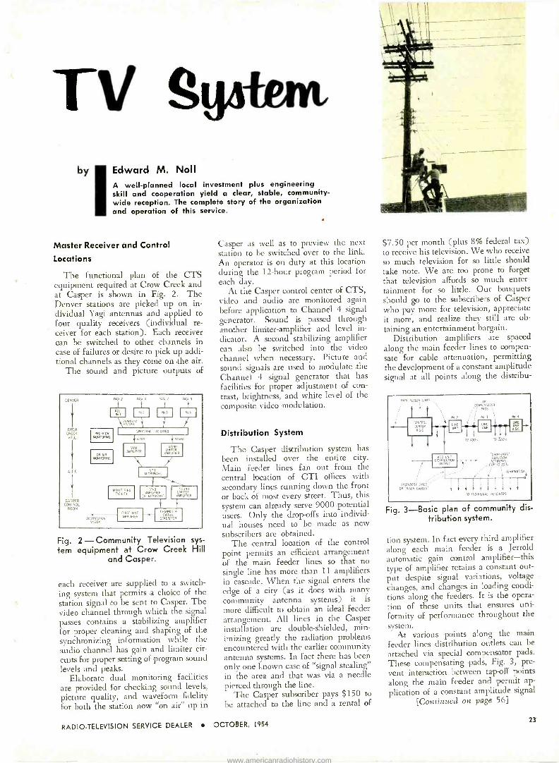
by Edward M. Noll A well -planned local investment plus engineering skill and cooperation yield a clear, stable, community - wide reception. The complete story of the organization and operation of this service.
Master Receiver and Control
Locations
The functional plan of the CTS equipment required at Crow Creek and at Casper is shown in Fig. 2. The Denver stations are picked up on in- dividual Yagi antennas and applied to four quality receivers (individual re- ceiver for each station). Each receiver can be switched to other channels in case of failures or desire to pick up addi- tional channels as they come on the air.
The sound and picture outputs of
DENVER
CROW LHLL HILL
CA PER CON ROL
ROOM
vACI 2 YAGI 0 MCI N
Fig. 2-Community Television sys-
tem equipment at Crow Creek Hill and Casper.
each receiver are supplied to a switch- ing system that permits a choice of the station signal to be sent to Casper. The video channel through which the signal passes contains a stabilizing amplifier for proper cleaning and shaping of the synchronizing information while the audio channel has gain and limiter cir-
cuits for proper setting of program sound levels and peaks.
Elaborate dual monitoring facilities are provided for checking sound levels, picture quality, and waveform fidelity for both the station now "on air" up in
Casper as well as to preview the next station to be switched over to the link. An operator is on duty at this location during the 12 -hour program period for each day.
At the Casper control center of CTS, video and audio are monitored again before application to Channel 4 signal generator. Sound is passed through another limiter -amplifier and level in-
dicator. A second stabilizing amplifier can also be switched into the video channel when necessary. Picture and sound signals are used to modulate the Channel 4 signal generator that has facilities for proper adjustment of con-
trast, brightness, and white level of the composite video modulation.
Distribution System
The Casper distribution system has been installed over the entire city. Main feeder lines fan out from the central location of CTI offices with secondary lines running down the front or back of most every street. Thus, this system can already serve 9000 potential users. Only the drop-offs into individ- ual houses need to be made as new subscribers are obtained.
The central location of the control point permits an efficient arrangement of the main feeder lines so that no single line has more than 11 amplifiers in cascade. When the signal enters the edge of a city (as it does with, many community antenna systems) it is
more difficult Ito obtain an ideal feeder arrangement. All lines in the Casper installation are double -shielded, min- imizing greatly the radiation problems encountèred with the earlier community antenna systems. In fact there has been only one known case of "signal stealing" in the area and that was via a needle pierced through the line.
The Casper subscriber pays $150 to
be attached to the line and a rental of
$7.50 per month (plus 8% federal tax) to receive his television. We who receive so much television for so little should take note. We are too prone to forget that television affords so much enter- tainment for so little. Our bouquets should go to the subscribers of Casper who pay more for television, appreciate it more, and realize they still are ob-
taining an entertainment bargain. Distribution amplifiers are spaced
along the main feeder lines to compen- sate for cable attenuation, permitting the development of 'a constant amplitude signal at all points along the dlistribu-
..IN FEELER ONES,
CONTROL
GE fl A.G.G
2
SECONDARY LINES '
OR 'RISER CAFiEi'
AOO UNIT DIGTRIBUTIO
OU Pur
IR COMPENSATOR
PAOS `,
Ma.3 i
LINE AMP.
TLADO's Rltooi
um
OR0P-OEES ISOLATION
(UP TO 20).
TERMINATION
i i i 'r
IO INOIVI000L RECOVERS
Fig. 3-Basic plan of community dis tribution system.
tion system. In fact every third amplifier along each main feeder is a Jerrold automatic gain control amplifier-this type of amplifier retains a constant out- put despite signal variations, voltage changes, and changes in loading condi- tions along the feeders. It is the opera- tion of these units that ensures uni- formity of performance throughout the system.
At various points along the main feeder lines distribution outlets can be attached via special compensator pads. These compensating pads, Fig. 3, pre-
vent interaction between tap -off points along the main feeder and permit ap-
plication of a constant amplitude signal [Continued on page 56]
RADIO -TELEVISION SERVICE DEALER OCTOBER, 1954 23
www.americanradiohistory.com

See For Yourself
Pt1111.00 SUPER PERFORMANCE ANC
TV
&---A QUALITY 67/72,0.,1
24 RADIO -TELEVISION SERVICE DEALER OCTOBER, 1954
www.americanradiohistory.com

GUARANTEED TO OUTPERFORM
ANY EQUIVALENT TYPE ANTENNA OR
YOUR MONEY and
LABOR COSTS BACK! There's been enough words written about TV antenna performance. Now
... see the facts for yourself !Compare any of the new PHILCO Super -Performance
TV Antennas with any equivalent type on the market. If the new PHILCO does
not give you the finest picture possible, your money back for the antenna plus
your labor costs up to $10.00. Ask your PHILCO Distributor for complete
details on this amazing offer !
PHILCO VHF
SUPER CONICAL
PHILCO VHF
LOW BAND VAGI
PHILCO TWO -BAY SUPER CONICAL
ALL -CHANNEL ANTENNA
Strong signal pickup on VHF channels 2 through 13 ... UHF channels 14 through 83 ... ideal for fringe area reception ... all - aluminum construction with dowelled elements: Part No. 45-3096-2. Rugged single bay design: Part No. 45-3096.
PHILCO TWO -BAY VHF LOW BAND
YAGI ANTENNA
10 elements ... all -aluminum ... factory pre -assembled. Top per- formance on channels 2 through 6 ...13 db to 15 db gain on various channels. Single bay Part No. 45-3112-2 through 6. Stacked ver- sion harness PartNo.45-3267.
PHILCO GOLDEN YAGI
UHF ANTENNA
Designed for 300 ohm operation .. all metal construction ... 11 db
to 12 db gain on various chan- nels. "Cronak" coated compo- nents resist salt air ... humidity. Six models cover entire UHF spec- trum: Basic Part No. 45-1996.
PHILCO PARAFLECTOR
ALL -CHANNEL UHF ANTENNA
Pre -assembled, all -aluminum .
8 to 10 db gain ... outstanding fringe area performance . . . im- mediate mounting on existing masts. Part No. 45-3071. Bow Tie, Part No. 45-3069 and Bow Tie with reflector, Part No. 45-3070 give top quality pictures in many UHF areas.
PHILCO UHF
GOLDEN VAGI
PHILCO UHF
PARAFLECTOR
PHILCO CORPORATION ACCESSORY DIVISION
"A" AND ALLEGHENY AVE. PHILADELPHIA 34, PA.
RADIO -TELEVISION SERVICE DEALER OCTOBER, 1954 25
www.americanradiohistory.com
A new standard in
electrical and mechanical
perfection in all ®, new YAGI antennas
Model #4165. 10 element
broadband Yogi.
Walsco's exclusive "umbrella" snap -out
design provides perfect element alignment
instantly.
Featuring the new WALSCO "Octopus"
Model #4110. A combination
Yaci-conical for superlative all -channel
reception.
211rt)I
"futurized " YAGIS
reach
everywhere
Model #4160 series.
5 element, single
channel Yagis.
NOW .... a complete line of 32 "fiturized" Yagi antennas with superlative performance ... for =ringe and filtra-frirge areas; for black and white ana color o -t all present and future channels. No kose hardwcre ... completely pre -assembled using Walsco's exclusive "umbrella" snap -out design. Nothi-tg compares at any price!
Write for complete information on all 32 'futurized" Yogi models
$1iN`1vA]n NJ;fPJ,2271J2 3602 CrensFmw Blvd. _os Angeles 16, California
O+erseas Distributor: Ac ALriema, Irc 89 B-oad St., New York 4, N.Y.
www.americanradiohistory.com

Do you have a vexing probi
or TV set? If so, send it in
this magazine. All inquiries
em on the repair of some radio
to the Answer Man, care of
acknowledged and answered.
4700
I/2 I2BH7 VERT. OSC
l ¡ 05,uF
-30 1' 470K I
47K 5 MEG
I.8 MEG 036uF HEIGHT
.02uF 11131111 6.8 K
47K I MEG VERT. HOLD
1/2 12BH7 VERT OUTPUT
420v
< 5 MEG
3.3K 2W
10 ONF
T 3.3K IONF \ 2W
1.8K VERT.
LINEARITY B++
TuF VERT. DEFLECTION
COILS
Fig. I - Vertical deflection section of the CBS -Columbia Chassis 750-3.
CBS Columbia Ch. 750-3- Height Shrinks
Dear Mr. Answerman:
I have encountered on several occa-
sions vertical deflection troubles that have caused me considerable difficulty in locating. The present case I have in
mind, a CBS -Columbia chassis 750-3, is a problem where the height shrinks after a period of about ten to fifteen minutes. The shrinkage amounts to
about one inch on the top and bottom and occurs very slowly.
What do you suggest as a recom- mended procedure in servicing this type of deflection trouble?
N.E. New Haven, Conn.
Naturally the first step is to substitute the tubes concerned, the vertical oscilla- tor and output tubes. In this receiver
these functions are combined into one envelope and the tube is the 12BH7 dual triode. The circuit for the CBS -Colum-
bia 750-3 chassis is shown in Fig. 1.
After checking the tubes a record
should be made of the vertical oscillator grid and plate voltages as well as the
vertical output grid and plate voltages.
These should be taken under the two
conditions, normal operation and when the picture shrinks. If a marked change occurs it usually is an indication of
which stage the trouble will be located
in. At the same time a scope can be
placed at the grid of the vertical output tube and the peak to peak voltage meas-
ured when the deflection is normal. After the height shrinks any change in
waveform shape or amplitude can be
noted for this input grid circuit.
If the waveform changes at the grid
of the output tube it is fair to assume
that the trouble is in the vertical oscilla-
tor circuit. Since there is no change in
the vertical oscillator frequency, the
change in waveform is probably due to
a change in B voltage supplied to the
circuit. The 470K resistor, the height control and the 47K resistor feeding the
B voltage should be checked while hot after the shrinkage occurs. With the receiver switched off the resistors can be measured immediately to see if they
have increased from their normal value.
There are other components that can
cause this type of trouble in the circuit. If the .036 pi charging condenser de-
velops a leak as the circuit warms up the waveform at the grid will be re-
duced in amplitude and the shrinkage will result.
Consider now that the grid wave-
form remains constant when the shrink- age occurs. If the scope is connected to the plate of the vertical output stage
the waveform at his point will probably shrink in amplitude along with the height of the picture. Another check that can be made at this point is the peak to peak voltage at the plate of the
[Continued on page 52]
Fig. 2-Schematic for battery operated scope pre -amplifier.
RADIO -TELEVISION SERVICE DEALER OCTOBER, 1954 27
www.americanradiohistory.com

by
I
Keg Tea PtinfA IIIIIIIIMNmmmizmsNmamimsmm
Steve Travis
Methods of systematic stage isolation and defective component pinpointing as applied to TV deflection, vertical and horizontal os- cillator systems.
The Deflection System
The picture and raster is impressed on the tube by deflecting the beam from the electron gun both vertically and horizontally. It therefore requires two deflection systems to accomplish this. The vertical deflection system uses a 60 cycle oscillator which moves the electron beam slowly down the picture tube face at this frequency rate. The horizontal oscillator develops a sawtooth of voltage which causes the beam to be deflected horizontally at 15,750 cycles per second. Both oscillators are locked in with the station sync signals.
The deflection system is the section in a TV receiver that generally requires more servicing than any other section. This is due primarily to the high volt- ages and circuit complexities found in
OUTPUT VOLTAGE
VERT HOLD
INTEGRATING NETWORK
111
BIAS VOLTAGE HEIGHT
VERTICAL MULTIVIBRATOR
OUTPUT VOLTAGE
VERT LINEARITY
VERTICAL OUTPUT
YOKE
Fig. I-Vertical blocking oscillator and conventional output stages.
the deflection system. However, it is only necessary to observe ordinary troubleshooting procedures to properly service the deflection section, as for that
INTEGRATING NETWORK
8+ HEIGHT
BIAS VOLTAGE
VERT HOLD
B+
VERTICAL MULTIVIBRATOR
OUTPUT VOLTAGE
B+
VERT LINEARITY
YOKE
VERTICAL OUTPUT
Fig. 2-Vertical multivibrator and autotransformer output stage.
matter any other sections. The difficulty is isolated first in its section, then to a particular stage of that section, and finally to the defective component.
The Vertical Oscillator In troubleshooting the vertical oscil-
lator the technician is concerned with the same approach as servicing other oscillator circuits. The key test point is the grid of the oscillator tube. Here the negative grid voltage is the key test point. As explained previously, whether the oscillator circuit is of the multi - vibrator or blocking type, if the stage is operating as it should a negative voltage will be generated at the grid circuit a negative voltage. See Fig. 1. If the oscillator is operating, a negative grid voltage will be present. The important point is that the negative voltage is generated in the normal development of the oscillator frequency, and there- fore indicates that is the oscillator op- erating whether of the blocking or multivibrator type. These two generally
28 RADIO -TELEVISION SERVICE DEALER OCTOBER, 1954
www.americanradiohistory.com
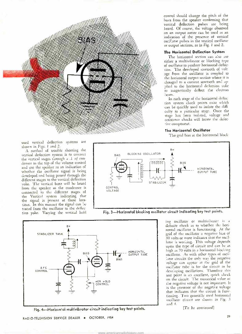
used vertical deflection systems are shown in Figs. 1 and 2.
A method of trouble shooting the vertical deflection system is to connect the vertical stages through a .1 uf con- denser to the top of the volume control and use the speaker as an indication of
whether the oscillator signal is being developed and being passed through the different stages to the vertical deflection yoke. The vertical buzz will be heard from the speaker as the condenser is
connected to the different stages of the Vertical system indicating that the signal is present at those loca- tions. In this manner the signal can be traced from the oscillator to the deflec- tion yoke. Varying the vertical hold
control should change the pitch of the buzz from the speaker confirming that vertical deflection pulses are being heard. Of course, the voltage observed on an output meter can be used as an indication of the presence of vertical oscillator pulses in the vertical oscillator or output sections, as in Fig. 1 and 2.
The Horizontal Deflection System The horizontal section can also use
either a multivibrator or blocking type of oscillator to produce horizontal deflec- tion. The developed sawtooth of volt- age from the oscillator is coupled to
the horizontal output section where it is
changed to a current sawtooth and ap- plied to the horizontal deflection yoke to magnetically deflect the electron beam.
In each stage of the horizontal deflec- tion system check points exist which can be quickly used to isolate the diffi-
culty to a particular stage. Once the stage has been isolated, voltage and resistance checks will locate the defec- tive component.
The Horizontal Oscillator The grid bias at the horizontal block -
BIAS
CONTROL VOLTAGE
BLOCKING OSCILLATOR
STABILIZER
B+
BIAS
HORIZONTAL OUTPUT TUBE
Fig. 3-Horizontal blocking oscillator circuit indicating key test points.
B+
STABILIZER TANK
A.F.C. CONTROL
NOR. HOLD CONTROL
HORIZONTAL OUTPUT TUBE
BIAS
Fig. 4-Horizontal multivibrator circuit indicating key test points.
ing oscillator or multivibrater is a
definite check as to whether the hori- zontal oscillator is functioning. At the grid of the oscillator a negative bias of 30 volts or more indicates that the oscil- lator is working. This voltage depends upon the type of circuit and can be as
high as 70 volts in a horizontal blocking oscillator. As with other types of oscil- lator circuits the only way the negative voltage can appear at the grid of the oscillator tube is for the circuit to be developing oscillations. Therefore this test point is an excellent, quick check on the circuit. The numerical value of the negative voltage is not important. It is the presence of the negative voltage that indicates that the circuit is func- tioning. Two generally used horizontal oscillator circuit are shown in Fig. 3
and 4. [To be continued]
RADIO -TELEVISION SERVICE DEALER OCTOBER, 1954 29
www.americanradiohistory.com

e.
cliii úy Cyrus G/ickstein
This fifth installment discusses the functional characteristics of complex RC circuits
with series parallel elements, and their application to TV sync circuits.
WE' have previously analyzed com- plex RC circuits with one con-
denser and two resistors. We will now find that complex RC circuits with two condensers, one series and one parallel, have some unsuspected behavior quirks.
Basic Action of Series Condensers As an introduction to these circuits,
let's review the action of two conden- sers in series across a battery, Fig. 23. When the switch is closed, current flows only for an instant. The condensers charge up immediately and current flow stops. The voltages across the con- densers add up to the battery voltage, since the battery voltage divides across the two condensers in inverse propor- tion to capacity. That is, there is less voltage across the larger condenser. For example, if Cl is .1 of and C2 is half the size-.05 uf-in Fig. 23, then the battery voltage (180V) divides inverse- ly across the two condensers - 60V across Cl (.1 uf) and double the volt- age, or 120 V across C2 (.05 u f ).
Series -Parallel Circuit Action When the switch is closed in the
series -parallel circuit with two con- densers shown in Fig. 24a, the battery voltage instantaneously divides across the two condensers in inverse ratio to their capacity, just as in the previous case. At this first instant, RI has no effect on the action. However, imme- diately after this first surge, R1 provides a discharge path for parallel condenser Cl while series condenser C2 continues to charge. CI discharges to zero through RI while C2, the series condenser, charges to battery voltage through R 1. Arrowheads show the direction of cur- rent flow in Fig. 24a. The curves illus- trating the voltages across each con- denser are shown in Fig. 24b and c.
Time constant for C2 is defined as the time it takes this condenser to charge to 63% of the exponential por- tion of the curve (Fig. 24e), disregard- ing the initial surge. That is, after the first instantaneous charge, C2 then charges in the usual exponential way
180
a)
+ .. rt Rr
Original Circuii
d1 t Equivalent --I-- Battery I 60 V.
20 K.
R,
20 K.
C Lc= l ,uf 05Nf
Equivalent circuit for time constant only
(across C,
120 V.
60 V.
E (across C0)
lóo v
120 V
60 V'
feo
r-w
b)
Charge 8 Discharge curve of C,
rmstant switch is closed
T- Charge curve of CZ
Fig. 24-Charging action which takes place in series parallel circuits. Parallel RC in series with C.
180 V _
e ,e
Fig. 23 - Two condensers across a
battery divide the voltage in inverse ratio to capacity.
from 120 v to 180 v. For Cl, time con- stant is the time it takes Cl to dis- charge to 37% of the initial surge volt- age. Since the circuit has one overall time constant, both events take place at the same instant.
Whether a condenser charges or dis- charges, the current through the circuit decreases. The current curve in either case is an exponential curve of decay. Therefore, the decreasing current through R1 divides-part goes to Cl which is discharging and part goes to C2 which is charging, Fig. 24a. This has exactly the same effect on the time constant of the circuit as if both con- densers are in parallel and charging through R1, as shown in the equivalent circuit, Fig. 24d. In the equivalent cir- cuit, the decreasing current through 131
also divides between the two condensers. Effectively, the two condensers are
in parallel and the time constant of the entire circuit of Fig. 24a (or 24d) is: T = (C1 + C2) x R
= (.05 uf + .1 uf) X 20,000 = .15 x 10-6 X 20,000 = 3,000 usec The fact that the two condensers in
Fig. 24a divide the battery voltage dur- ing the first surge may seem at first glance to reduce the time constant of the circuit. This however is not the case. A simple example will clarify the situation. Assume we have a simple series RC circuit across a battery. This circuit has a certain time constant based on the value of R and C. Now before the switch is closed, another condenser of equal value is placed across the re- sistor-a circuit similar to Fig. 24a. When the switch is closed, the series condenser C2 instantaneously charges to half the voltage, then more slowly charges to the other half of the voltage. Current for the initial, instantaneous charge of the two condensers does not flow through the resistor at all, but through the condensers only. There- fore, series condenser C2 has to charge slowly through the resistor to only one- half the amount of voltage as compared to a simple series circuit. However, in this series -parallel circuit, initial cur- rent through the resistor, after the first surge, is also one-half compared to the initial current in a simple series cir- cuit. This is true since only one-half the source voltage appears across Cl, which is in parallel with R1. Note that
[Continued on page 57]
33 RADIO -TELEVISION SERVICE DEALER e OCTOBER, 1954
www.americanradiohistory.com
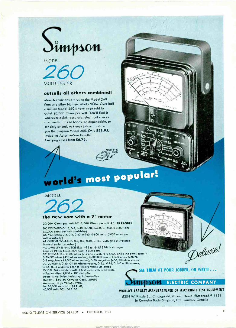
MODEL
260 MULTI -TESTER
outsells all others combined! More technicians are using the Model 260
than any other high -sensitivity VOM. Over half
u million Model 260's have been sold to
date! 20,000 Ohms per volt. You'll find it
wherever quick, accurate, electrical checks
are needed. It's so handy, so dependable, so
sensibly priced. Ask your jobber to show
you the Simpson Model 260. Only $38.95, including Adjust -A -Vue Handle.
Carrying coses from $6.75.
AOIUST-A-VUE
8andlt
the new vom with a 7" meter 20,000 Ohms per volt DC. 5,000 Ohms per volt AC. 33 RANGES
DC VOLTAGE: 0-1.6, 0-8, 0-40, 0-160, 0-400, 0-1600, 0-4000 volts
(20,000 ohms per volt sensitivity) AC VOLTAGE: 0-3, 0-8, 0-40, 0-160, 0-800 volts (5,000 ohms per volt sensitivity) AF OUTPUT VOLTAGE: 0-3, 0.8, 0-40, 0-160 volts (0.1 microfarad internal series capacitor) VOLUME LEVEL IN DECIBELS: -12 to +45.5 DB in 4 ranges. Zero DB Power Level, .001 watt in 600 ohms. DC RESISTANCE: 0-500 ohms (4.5 ohm:. center); 0-5,000 ohms (45 ohms center); 0-50,000 ohms (450 ohms center); 0-500,000 ohms (4,500 ohms center); 0-5 megohms (45,000 ohms center); 0-50 megohms (450,000 ohms center) DC CURRENT: 0-80, 0-160 microamperes, 0-1.6, 0-16, 0-160 milliamperes, 0-1.6, 0-16 amperes (267 millivolts maximum drop) MODEL 262 complete with 2 test leads with removable alligator clips, 4,000 v. DC multiplier Dealer's Net Price, including Adjust -A -Vue Handle . .$59.50 Carrying Case ..$9.95 Accessory High Voltage Probe for 16,000 volts DC. $11.50, 40,000 volts DC .$12.50
F. T
s`0, -t '10
4T 'SOUR JOBBER, OR WRITE ...
ELECTRIC COMPANY
WORLD'S LARGEST MANUFAC'URER OF ELECTRONIC TEST EQUIPMENT
5204 W. Kinzie St., Chicago 44, Illinois, Phone: EStebrook 9-1 1 21
In Canada. 3ach-Simpson, Ltd., ':ondoya, Ontario
RADIO -TELEVISION SERVICE DEALER OCTOBER. 1954 31
www.americanradiohistory.com

FOR GREATER PROFITS SPEED UP YOUR
SERVICING
with THIS NEW BOOK
which shows you how to take care of and repair in the quickest possible time:
Common troubles characteristic of certain receivers "Bugs" which might take you hours to find
o Factory and field service changes
SET UP SO THAT YOU CAN MAKE THESE REPAIRS IN THE SHOP OR IN THE FIELD WITHOUT REFERENCE TO ANY OTHER SOURCE
Contains over 600 Service Items representing over 1000
of the most -serviced Televi- sion models now in use.
Over 25 different manufac- turers' lines are covered.
$4.95 postpaid
(Add 3% Saies Tax in New York City)
DISTRIBUTORS-ORDER YOUR SUPPLY NOW!
Service Dealers-get your copy of VSSS from your Distributor. If he can't supply you, order direct by mail from us.
Video Speed Servicing Systems IS GUARANTEED to Simplify Servicing All TV sets. A number of new Data Items are published in every issue of "Radio -Television Service Dealer" as a regular monthly feature.
TEAR OFF AND MAIL NOW.
RADIO -TELEVISION SERVICE DEALER
67 West 44th Street, New York 36, N. Y.
Please send me post-paid VIDEO SPEED SERVICING SYSTEMS Volume 1. Enclosed herewith is
my check money order for $ for
Name
Address
copies at $4.95 each. (Add 3% Sales Tax in New York City)
City ..Zone State
32 RADIO -TELEVISION SERVICE DEALER OCTOBER, 1954
www.americanradiohistory.com

WAR DECLARED ON DEALER CALLBACKS!
Other Sylvania types are vastly im- proved, too! All have Sylvania's fa- mous wafer stem construction, plus these additional design features:
Better Lead Spacing Stronger Mount Supports Stronger Micas Firmer Filament and Plates Greater Protection Against Shock and Vibration Better Heat Dissipation Low Glass Electrolysis Fewer Burnouts Stronger, More Rugged Overall Construction
NO MINOR SKIRMISH The Sylvania war on dealer call-backs is not a minor skirmish. It will con- tinue until dealer call-backs on these and other receiving tube types are completely eliminated. The dealer's
NEW TUBE TYPES FROM SYLVANIA SPEARHEAD ATTACK!
The most important step in a concentrated campaign to eliminate dealer call-backs has been taken by Sylvania with the release of a group of new tube types. Sylvania's new 5U4GB leads the group.
The 5U4GB attacks the call-back enemy on many different fronts:
1 The tube has been re -designed. Now, plates are longer and heavier with twin wings for better heat dissipation, Sylvania's 5U4GB car- ries increased ratings of 275 ma at 44 volts drop with 1.0 amp peak plate current.
2. Wafer Stem Construction-originally developed by Sylvania for the lock -in tube-has been adapted to the 5U4GB. The wafer stem elimi- nates electrolysis, provides stronger mount construction, permits better spacing.
3. A new T-12 bulb provides greater heat dissipation, gives added strength, more rigidity because of its straight construction.
4. Bottom mica has been added to make the tube stronger, improve filament alignment and eliminate arcing.
biggest profit -robbing enemy can look forward only to an incessant, contin- uing effort on the part of Sylvania to make his existence a thing of the past. These quality tubes are now at your Sylvania distributor's.
SYLVAN Sylvania Electric Products Inc. 17' 174C Broadway, New York 19, N. Y.
In Canada, Sylvania Electric (Canada) Ltd., University Tower Bldg., St. Corherine Street, Montreal, P. Q.
LIGHTING RADIO ELECTRONICS TELEVISION
TO IDENTIFY SYLVANIA'S NEW
RECEIVING TUBES LOOK FOR
THE NEW CARTON!
This new tube carton identifies Syl-
vania's new high quality, improved receiving tubes. It's assurance to dealers everywhere that inside is one of the finest receiving tubes made- unsurpassed for quality and perform- ance. For further information write to Dept. 4R-3910 at Sylvania.
RADIO -TELEVISION SERVICE DEALER OCTOBER, 1954 33
www.americanradiohistory.com
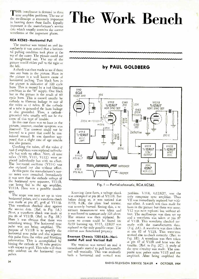
THIS installment is devoted to three sync amplifier problems. The use of
the oscilloscope is extremely important in hunting down these faults. Equally important is the manufacturer's service data which usually contains the correct waveforms at the important places.
RCA KCS82-Horizontal Pull The receiver was turned on and im-
mediately it was noticed that a horizon- tal pulling condition took place at the top of the raster. The picture could not be straightened out. The top of the picture would either pull to the right or the left.
A check was then made to see if there was any hum in the picture. Hum in the picture is a well known cause of horizontal pulling. Two black bars in the picture is indicative of 120 cycle hum. This is caused by a bad filtering condition in the "B" supply. One black bar in the picture is the result of 60 cycle hum. This is caused usually by cathode to filament leakage in one of the video or rf tubes. If the cathode of a tube is grounded the hum leakage is also grounded. Thus, a cathode - grounded tube usually will not be the cause of this type of trouble.
In this case there was no hum in the picture; however, another symptom was observed: The contrast could not be lowered to a point that could be con- sidered normal. It was therefore sup- posed that a slight case of agc trouble was also present.
Checking the tubes, all the video if and rf amplifiers were replaced individu- ally but with no effect. Next, all sync tubes (V109, V111, V112) were re- placed individually but with no effect. The horizontal oscillator (VI14) was also replaced but also without effect.
At this point the manufacturer's serv- ice notes were consulted. Immediately it was seen that the cathode voltage of the horizontal sync separater, V111B, was being fed to the agc amplifier, V111A. Here was a possible trouble spot.
The scope was next set up to view horizontal pulses, and a waveform check was made at pin #7, grid of V111B. This waveform checked okay against the service data. (Ref. to Fig. IA.) Next, a waveform check was made at pin #6 of V111B. (Ref. to Fig. 1B.) Here it was obvious that there was something wrong. The horizontal sync pulse was not being amplified. The purpose of V111B is to amplify the horizontal sync pulse and also separate this pulse from the video and blanking information. This is accomplished by biasing the cathode at 70 volts positive with respect to grid. This tube will then only conduct on the horizontal sync pulses.
The Work Bench
by PAUL GOLDBERG
V110
6CL6 VIDEO AMP
6
270 V.
V111A
1/212AU7 A.G.C. AMP.
A V111 B
PIN No.7
18K
V1118 C149
1/2124U7 270 HOR. SYNC SEP t
6
270 V.
22K
R163 270 K
C150 330
Defective
V1098 '/212AÚ7
VERT. SYNC SEP.
270 V.
BmurrmsztagamanyIMPROPER V111B
PIN No.6 PROPER
V112Á
1/212ÁU7 SYNC
OUTPUT
V114
6SN7 HOR. OSC.
--> V1128
+124U7 VERT. OSC.
Fig. I - Partial schematic, RCA KCS82.
Knowing these facts, a voltage cheek was attempted at pin #6 of V111B. But before doing so, it was noticed that R159, 8.2K, the plate load resistor, was severely burned. Seeing this, a re- sistance measurement was taken and it was found to measure only 125 ohms. The resistor was then replaced. Be- cause no reason could be found for R159 burning up, V111, 12AU7 was replaced as the only possible cause. The receiver now functioned properly.
Emerson Chassis 120162A-Hori- zontal Pull and Vertical Roll
The receiver was turned on and it immediately started to pull horizontally and roll vertically. This was evidently both a horizontal and vertical sync
problem. V 11 B, Ufa 12AÚ 7, was the only composite sync amplifier. Thus VII was immediately replaced but with- out effect. A search was then made for hum in the picture but there was none. V12 was next replaced but without ef- fect. The oscilloscope was then set up and a waveform was taken at pin #7 of Vi1 B. This waveform checked cor- rectly with the manufacturers data. (Fig. 2A). A waveform was then taken at pin #2 of V12A. This waveform seemed also to check correctly. (Ref. to Fig. 3B). A waveform was then taken at pin #7 of V12B and here was the trouble. (Ref. to Fig. 2C). A study of the sync circuitry was made. The com- posite sync pulses enter V I 1 B and are amplified. After being amplified the
34 RADIO -TELEVISION SERVICE DEALER OCTOBER, 1954
www.americanradiohistory.com

A V11B
PIN No.7
B V12Á
PIN No.2
C V12 B
PIN No.7 rpJ! 5P,,IW10J AiYI n,'I,
V12Á
1/212AÚ7 NOR.
SYNC SER
---; HORIZ. SYNC £' PULSES
VERT. SYNC PULSES
CORRECT
R55 1OOK
V11B
1/212ÁU7 SYNC AMR
+140V. +210 V.
V12B
'/212ÁU7 VERT. R56
SYNC SER.
6
7i
C40
T 47µ}ií _ J_
INCORRECT
10 MEG.
140V.
V13
6SN7 VERT OSC.
Fig 2. - Partial schematic, Emerson 120162-A.
composite sync signal enters a network (R42, 2.2 meg and C30, 220 mmf) at pin #2 of V12A. This network has an excellent horizontal sync pulse to noise ratio. However, it attenuates the verti- cal sync pulses. To improve on this
situation a low pass filter (R55, 100K and C40, 47 mmf) is employed which increases the vertical sync pulse to noise ratio at pin #7 of V12B. Thus, due to
these networks, only the horizonal sync pulses will be amplified by V12A, and only the vertical sync pulses will be
amplified by V12B. To get back to the trouble now and referring to the incor- rect waveform in Fig. 2C, it is evident that very little vertical sync pulse was getting to the grid of V12B. A resist-
ance measurement was then made from
Pin #7 of V12B to ground. The meter read about 500K. C40, 47 mmf, was next clipped from the grid, pin #7, and measured. It measured about 750K ohms leakage. C40 was then replaced with a new condenser and the receiver functioned properly.
Because C40 was leaking, horizontal as well as vertical sync pulses were be- ing amplified by both V12A and V12B. C40, normally would kill all horizontal sync pulses arriving at pin #7 of V12B. Moreover, the vertical sync pulses no longer had the easy path of R55 and C40 and so they divided themselves be- tween the grids of V12A and V12B. Thus, the diminished vertical sync pulse caused the intermittent vertical roll and the vertical sync pulse being
This Month:
SYNC
AMPLIFIER
PROBLEMS
allowed to trigger the horizontal oscil-
lator caused the horizontal pulling.
Motorola TS114-Intermittent Hori- zontal Pulling and Vertical Jitter
The receiver was turned on and it was observed after a time that the
horizontal began to pull intermittently and that the vertical had a bad jitter. Inasmuch as there was no sign of age
trouble, we decided to check the clipper circuits. V12, the cli?per, was replaced but had no effect. Next the scope was
set up and a waveform check was made at Pin #1 of V12A, the first clipper. The waveform however checked cor-
rectly with the manufacturer's service data. (Ref. to Fig. 3A.) A waveform check was next taken at Pin #2 of
V12A. Here the waveform was not cor-
rect. (Ref. to Fig. 3B.) The purpose of
V12A, the first clipper is to remove the blanking end video information and
VAHO VIDEO AMP.
850 40
a, LOO
/ v124 C58
`e3 T` 1si165PVE8 .05
1
Leaking ,
RIN AID.l
MCG
MEG.
1$
PROPER
VIDA r Y
PIN Mo.2 IMPFOL:-'
28 'h65N7
v4.GlIPPEp
6415
6SN7
Fig. 3 - Partial schematic, Motorola TS 114.
amplify only the sync pulses. C57 and R5I form the cutoff grid leak bias for V12A. Because of this grid leak action, V12A will only conduct on the sync pulses thus eliminating the blanking and video information. Now the wave- form taken at Pin #2 of V12A, you will notice, contains all the video and blank- ing information. This should not be. Refer to Fig. 3B and the correct and incorrect waveforms can be seen.
[Continued on page 56]
RADIO -TELEVISION SERVICE DEALER OCTOBER, 1954 35
www.americanradiohistory.com

U SS ONE SOURCE
TO MEET ALL YOUR FUSE NEEDS!...
Constant research and engineering over the past 39 years have resulted in a most complete line of BUSS fuses: dual -element (slow blowing), renewable and one time types ... in any size from 1/500 amperes up - plus a companion line of fuse clips, blocks and holders.
To make sure that BUSS fuses meet the highest standards of dependability ... every BUSS fuse normally used by the Electronic Industries is tested in a sensitive electronic device that automatically rejects faulty fuses.
Many manufacturers and service organizations have standardized on BUSS fuses to simplify their buying, stock handling and records - and to safeguard their good -will and reputation. You too, will find it good business to let BUSS meet all your fuse needs.
BUSS is the PROFIT brand because it is the KNOWN brand.
BUSS fuses have ready customer acceptance. The millions and millions of fuse installations for home, farm and industry have firmly established the dependability and unquestioned high quality of BUSS fuses. And BUSS fuses stay sold because your customers stay satisfied.
Makers of a complete line of fuses for home, farm, commercial, electronic and industrial use.
USETRO N
TRUSTWORTHY NAMES IN ELECTRICAL PROTECTION
FOR MORE INFORMATION MAIL THIS COUPON 3
BUSSMANN Mfg. Co. (Div. McGraw Electric Co.) University at Jefferson, St. Louis 7, Mo. SD -1054
Please send me bulletin SFB containing facts on BUSS small dimension fuses and fuse holders
Name Title
Company 1
Address
City & Zone. State._ 1054
36 RADIO -TELEVISION SERVICE DEALER OCTOBER, 1954
www.americanradiohistory.com

TV FIELD SERVICE
f..
rQ .. .r .. ..
1/ UZo x
CD p
el P.m RtnGV CD u CD oCV mD
N I
co o . ° q 1 - a v, p- o
y ó > > o ., r y i a ÿ Ñ .
ß MO O O Ó -o " a . : .. N.
ó + á 11 N. x Ln ó
co > r' 1-r r --I w F' t+, ^? ó ó ó
m :; N :j 'Ç + ó t2 ed ti = r p.w t
.
o Y
(
Pre -published from Rider "TV Field Service Manuals -
by Rider L Albcrg
Coplrrghr 1954, John i. Rider Guhh.he., Inc
¢Z > J
M 1---
Cs csi. m 0 ; O Ci, .-+
7J 'c0 p Qr +.+ O O W
C) ,y l- ÿ qy P+ P. m - Ñ r'
C I-- Ó. aV, GV m G
u o ¢ a a as ¢ o > Z ., p tn Á. .. " o° ÿ o o á .9-.. ó w o co ti 4. ti g ¢¢¢ a° a> o m'*' %ti O A m c. o a o á o
LL " "- e f34fs - 0 a. *' A o C a'= °0
co) o
Z o 5,c-).. O
w w bty.s á- Ó V' ó ó > r.W Á. tu
O CV ,t _ x x x +J cvmG >cñ> ¢ cx ¢axxAx-. ä CL.
Ñ vi m u w ¿ VH 5b LL r^r >
u- >-
r- o c\oLnSnInCDt G. o 2
CC o ~ a w waaa ¢ xwZ a>oaZaXm > Á CO c0 I- ,_, PZ ¢ ZZUUU¢ ¢ W up ¢ ¢¢¢¢¢¢vZ¢p;
LL. r ch doev0 v0e ve \ctr. GV á.
r_
GV í. O
-° m Li1 ä ä W ä g , N C>7 cT+ 0?3 5f o?f L ;- oo co, ó .-1 N l- rl r.' Ir- °1-° Ñ cOV Ó o
O ° v ÑxEE=-F=É-1y>?¢¢ >»s> *
RADIO -TELEVISION SERVICE DEALER OCTOBER, 1954 37
www.americanradiohistory.com
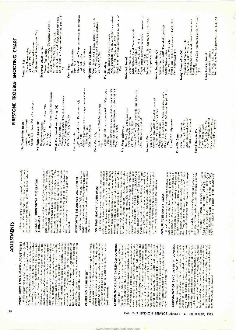
ó w .°+ 0 o a
:9 -9,, c o +°+ ae e0 m F
ú q E .~, m c C .:; E' H ó ,o
EaCt.1
a F v °~ ám.. ê M u c+
É ó v ú ÿÿ
ó 321 c 7 A ° 8 .] r 7á p m
.s;
O óF
F
'a m ÿX
G c
v^.
>avN O
t i ÿ vn Ñ B o
C °;E2p 0 61 qu>c .
Ñ E F w o 3.712
a. O
Uú máu
8 TÓU
vuú8 t
to Eo>M..'2gba ..
a H d ahâ W.
....t c 'w oG °Q á0. O Uá> ,C> ál .e > ÁE 'UÿR1y Ó T A C g.AY>
°°- Ó
yXF0 T>E CaÓ .b F XkC.r. Ñm
°~t ,= q «aCd
'a á>o a qya,w ccgÿ rocr,
o l áO, Q. á>á>á Nvg a° d> EI véoEa> kCa>Ov aop qd ".r°w 52'x ,cy çHW EN>o .w
ÉÁ>Xv FéoR:
CGEy..mr.m avEá a v> m..xá . "áY> Xp .. > ÿx> X2 y t'XXCqÑH> .oâ O. EX 'O " o E .kXbti N.>vu J.> .2 ,U+(Ca º E+ÚRÚÚ>
q.. -V éao mFnOuw OUr C oU c> « ºUOcaG ów
vi ?4aô,cá txU m xc>Uoc
NP
FCU, âmA a°UvA .0..]
.put
2 x ö 3 z ñF>m
m c
Ú ó
O m
v . c
he 8 ¢ > Ey Q 'o
w á U ó m >
A g e ''' ix R
« ;:. Y a; o
> t; c m U v >O. oo'wURN'. -0 q x -0 04-;' . . Caa.a
>O >O
a Z 2.,-1- 42
M Ñ F I :º I c;H
W>.,C>yO x P. !el' óCe7¿> á ó.^.c a>U
q>wx FUU>ó e z z 3
wo Ñ m ETl á "23 á°ti Oa ¿,
Ó s k ° ó ó c 3 f. 'p m^R. O
Q R.m wg.c ..°. a
.... --c-.3,.000- (7)R+ = M â äó c T °«
O :c C voa-. m.. v
Q á'w Eÿ Ó m
Z gÿ« oR g E
o C 08g4134-3 N .2 >4"-',9, x Fo
Ñ'F E° Ñ" u.^ d
tT.
= m a. d ^°
w« Ñ
Ow %
m g v
ZÚU Gó12 G S-_^o".ivC^y UQ 2 ó=sR' M 3.a,
~f
B
.
aw
wi.
F c
.Ev' s
cT
:
ôvpBN
. w C,Lôá mRÑ
mâ'P.m7F F>FáóR4%
Ytive5c.? u.+a, ÿq7.-^ió>,OOyvN O..mvVg _vam*Z"aiyWá.
Róaa7?a°u7cRÿ^7C w m Qg2.RgC,.rR o
mpwyÑw.ßFÓCcMïáaRgRwC.OO,d ów °..Qm.2° °.?So«váá 2Z
;at'c.c2RdmoRaE.svE .c «vo v ;; v ^EVRvXm>MG gm u-52-= .1 ú Y« 23 r, ...--2, :g.,
a«Q FGo
áv
2,A a ° y PT' '''3 41 .c QCE x.
C
y^
0.wúó ú: cG'âOC«
ái ó . m
W ô.. p q
0.1> m o 7 w v E q
O ô a°.., t> < 8 .` ,° F ri v ó M;+aqc mU>vm
fi G. u> ú'q E U R ° C b° a` O T
.C-+Ci; E ..a' ÿw 00
ô+ E : v A
> W , ô w ,p., axÑ F dx H>o w tiU> cxi ó ,ti, á
a>Ú uvTi ó E:.i>000> x ï
m ao
Ñ m.E. C 'O
X.O+ g ,°) d ,q
ô ia:, -o.0.2. a- ô > a C
3
E N
c « ó . aM t,5
0.AW1
R ú a 5R'ÇcRp c óy 'î,!A.a V..
p w,m R¿,C Q i 50 T áyâygXác°«g]VÿRUj
v. VÿCyRMóy O"E g«ET"v. áM m 3o3.cX;,«ÿa ORRRyyyñRCó
«v 4w7 GTaÑO «.m mß++C_amíiUvm.°w Úvvmm.RÑR,.á ti`gfOaCEÜ.avm , éá3 :.ó 1dcy
M
? e .áaaa ZW E°ó«PqR.q°aÁO
ÓyCw,C Em+.wTG
ämMvóác a.'0a,a.,,kQac°°mE¿
w i W mEEp .ó âm1M a
t- 7":74 u AWZ
AF .rF Fió Z we
Cd'avm
O
m
a°
d á ° m
Ç V V 8
áeaq. 14,0e-.5 Ú
T5.2,213". g
v C .p+'F « v a- 08Z. g Ci
W V V R w ÿ a C
R' m y C t+
37 G Ó EO m v .+ vp
q C uR Q ÿ . Op v ^
m
ú 60° ó t`".
.G ' W :' .4 Zwpa.t b tL t.,
O M á aut.,...,R a.,i t1
v
G
q á p
m ^á
i ó W
EW,
,'J E¡ aa ó xxaCW...vg. F+0>za G.FamWa .
00 0cAcUuó7 m
aÚGlxWÿV noa,d.W
Qgw« 5mvg mô Pcx
xFwOW35xWXv,C
wa Ov_y7 puuó« «y a G.Oa >w,.dÿRwag.B vú A G
in
~ T O o C
aFmUP°..ÓCÉ.Qq°F
á0 wáF°CvÑma «v 3 ZW c m m,yÿm I v d0 m v Wi'UW
Ota Rp,g.Mÿv+A o°00.,.7F AU = B>°0 ° F
ÿ
w .óyFu:áÿwvvvóG,vUC,.]xW
E omo«wÿ E .UF.]
C á p0 a b y« ÿ0 ÿ« m a Ó atl oa' M w C? v Co 3 c R M«
c v R . . ° ú u G p
ac, g y ów'öéaP.m gwÿwo Z E a vaRaavm
v w vcdacBwv3 ° 40.4w040 00g y.^. .n.., ÿ ô ,! m Ó ÿ y ..^. .a aC > ° V° W ~, C éoó' w« u> -B cdaw ¿wút° c.q66c vtiv3 g'mRm"g p.,ñ
vl M g v V E1 V aV+
am,Mûcvó"ÿBûUCGRRt: F,p"óggaRcuwE C u v m - . O m O m ,-. v ^ m . w m;p ` ^, « v
U C,°; C,i (7 -'.+ O V Ó g,v, E .+^M Z
t°, t°i m O R q a+ a+yC^+' C
.°F, :d A v 7a q ., 00 .'
O R m+'AEi V F.y E
e 'j;
m LL F Oy
E vÁ v 6^ â E m v . M B tg, tq i myRv ° v ç E8 , sq. ÿ v.^ ó v mLR
ÿy.aúc.a,_-;mTyºá
03,apW, mv
ág
wcg."n .EXúMCpig Rgm.ggámom, ú -ac w°Ba^móúRgwq^^rMg
38 RADIO -TELEVISION SERVICE DEALER OCTOBER, 1954
www.americanradiohistory.com

TV FIELD SERVICE
3 (13jJ i 11,7% °/.7. \>
Pre -published from Rider "TV Field Service Manuals.'
by Rider L Abber9
Copy,,ghf 195(1, /.A- { Ride, Puel,rlre,, lot
9 g O v ,m
2 1
l - v
(1 Oum9 / m O
gL_ 20201112® EI C%
..e
o U C) U U y cC o ^6 'b
^LS ^O no ^O ^, > > > > > > s ÿ
C ó O O CCD
CO CC `t? 3 a
I_ -o , "
i Lr
LP) E Le N r--1 CV Lf;. e --I m ÿ
K^ö C f~ . C C C acdi 3
Ir Dl.... -.0 a j a a. ,c;), a a a. .ñ á ^ La- sr-a0-. > m> >o> ó> 3> f
c + x O
U DM> > O C) Ú Ú => ^'a.y
m J "" p v +-. C4 l'° c = La
e. m °3 :; d > m
+ O eC Ld y,
..^"w CM 1i Gl, a.. - C.^ > =
3
Ó Ó Ó CD y y Ó C C y y
Inu t- Ó Ó CD Óc = CJCJCJ c') c3 -
P. P. acs.PI.
óóóóóóóó I-- CCCCCOCCCC N N N N N l`- t- N N r-
u- Lf3 UZ UJ L(') le CD Lf) le ul Ln
CJCC,)C.7C)C.)C7ÚCJCJ
a.aaa.aaaaa.c. e ee ef rf rf ce ce rf Q (24 g4 a.,aawaaaa
W N N N t-- r -I r --I CV CV CV CV CV
N LU,.."
Q MLnI--ir-,--i CV
Ó Ó Ó Ó Ó Ó Ó Ó Ó^ C9 C9
O ó ó C9 C9
u a o G
,Sa < ri. cu
a
Ó Ó E m c Ó 5 ó a> bQ o o o CD CD a ^d ó m , CU. a"i
CO a
.Ji el
Fi ó ó cea > > . >,QQ,> >xxaxaa F
áa áá ¢ á á>áQ> pzmxÑ UUCJcV U<Q¢dcqQ cl und134CQZDN,-- ><CC4-, YOeJr. ev^ e ^VO,-a\O\D .-. D D : .4 LI") ~CV
p r -I CJ m.cf, Lf) \[1 C7 CV
Lf \p N Qp N CV »» »»>>» »>»» »> RADIO -TELEVISION SERVICE DEALER OCTOBER, 1954
39
www.americanradiohistory.com

O ÿ F V
tD +
F o u v >
Y
° °x á
J.
s Y °g
c V
V roV a 1ro ro
óc 23 ro ,i Oÿ K no um S CJ
GuC mN
a á G F ( Vw
O > Ó0 O LT, , VOr. 7 VFYaX
V 38 2 24N ppGV m° O
W X Y.VOt tiá Ña Ñ OF . ú >ÿ F., óF r.Q O ,x uoce
O . = ó .g..2.g..2.0_, ZGoo-.02 é t^:°rowm >ro Qá dáYNua i'.4-.4C Ot2;-.4 Occ.w
úi áó^°á ú>°ÿ°z>O>
ó roOgY> f.>tn > Le Z.oO>> ó V ZM2d7V 02233P7 NOWFC.rO OF. mj:Oál>".,-nuvQoxM> x2
Z
,g- ,:2 Li WFCúd a oro; i x CFVá1 O...CU WO.r,C O WvíNCYO aaF~.°V
'O -y. »>UW^) m>U a »7U >. >V »U N
VI
Lu z Z Z O O Z z
H 05x
a
>xrox>O >v .N.áw Qu+c%
Q»Ú^Ú > O O.
60 y° .::
LC ú ÿ G C v
v o C
z . V C N2 F F F w V
ÿaYÿLm °°ÿ{°E t C. ̂ ^2. f0 td
a .0 v V b ,.,
Y A Y m
._o ó ÿ ç, 3 ba.,.0, q ú v =ouvro.erou..crocÿ oOVaHVUVAYÑ O
° c ro
tQE^móG°m° °á9áç O
O .^
a E
s ó° Y mC p, e m ó O ÿ ta V u NE u C Ó V ^7` T 7 .s,, boU o u L u
E,ro mF Óg a C
F ÿ Y ta oc a,c 3 . m G m a m° g ÿ m x
roQ,d+E,,;G°' F O V R
Á Fo 0 a v AW
u Qoi E .. E m v w v
adj ,t ,..+
'g Ó ro F C F
V á W E F Ñ Ñ E7 tQ Y W .c.: ;,u ;QE á Y O ÿ E. u L Ú G! 69
G m^ G ó"ÿcaÿLta0.¿g O Y
CO t> ta Ñ Ó q' 2 q C Ó
Ñm%'óíx.vóroFmv V U .O. {'.
O ... F W .0 a.cu.^ g ta v o Y w Éo,,,,3wFFmÁpx d Ow Á O A H o Á E
FN
7 .0 ¢,
G Ñ Ó O á ro
Yu.
3 L óo o o
ó 3m = á a FºmÁ
S 0
> ° c > c > ^ c g
d â u 0 t0 ÿ Y
N ÿ to
ro > c°i
c
ro x C O G .o..°. Qi ro Ú V
P4 V V C Q. > ro a
áo
Yco
=
ú 73 E V ú Z, >CC dCC
?,. ro Ú áá ú OUó> Ó
3 O u WC w °aroú.YÿWUC..jwqWr
p.,rj o WOU>a.roNÓÑU2
W C J N . x
w x ro a 4
O ' 1---rF Ú a,Ñ Q>G C uzu-iow,r>yj
i Á ÚyjL>X °
>z> >' >o HUU U X X Z O. a W
uoáFb°ngY ÿo ÿám mwmw áÑ3 w E F F
p2 su. ° w ta r. 0 .7P' N L ÿ L C%
N
v Q oFaEó vg áó boY.3 .`'.c á ÿR w fy O .. y C '. y Y
ÿC ÿ ÿ R Ñ U tE : °m . Y
F vi t0. c 3° C
°'
-5-Q1' L V '""'''15'°2 u uÿ u aro c
.b U Ú --2 ̂ W ta ° C -....2._. M
Ú ÿ L F. Y F Ñ v á ro YC
ta 720'o C 0'4 O
Ñ ro ÿ 6uq.^mm` °z oóm«uYc' á >,m°'roáoW3Uo c aóuB c
F C á ro `tl ro U u Ó 0. ú m m C >9+º.2-12°' m
m_v V F
^ E a m GY áÉ..R." QiY óF = á u°rou = E a ao o ro c m c gg a aÿ. ä. v coi t°. °D. éb á ó c>f.-;4:75:42:'; C ° g ÿ E c > F c ..L.>aomp^.óa^oÿÁÿsó" cE
Fro
.yA
ÁY E ÿ á ÿ " ; YC G ÿ m ro ÿ ÿ
F
- d ?O o 7+'CúACÓCáEYNCÿR ºF. Q, ej. uFa` .%V 3 ocH .°óa
3 bE .. ci .. 4 .ri :ri
O C ÿ 1S1.- ...., FroH E ..
G T 7 iO. ÿ V . C O ÿ 7? EE zEv;,
C Y U F
;C Fu. Ó
g á F ia ...L., a p á+ O ,tcce
m>
c
'u
w U ap. Z roH
2-1-C 1.',3 .0.0
Iii4fiEº
w
ÿ Qx men E.0 V" V O v
u A Y C 0> F u> ."52
z g.2
R
40 RADIO -TELEVISION SERVICE DEALER OCTOBER, 1954
www.americanradiohistory.com

TV FIELD SERVICE
o
(D LL Li.1
<L f Z Z O o J H Ó >
o
QCV M LC) N CV rn -N
Q N
1.0 N m -N
* N * N -0
Co -
L N N
Pre -published from Rider "TV Field Service Manuals'
by Rider B Alrberg
Copyrl9hf 1954, John F Rlder Publi,her, Inc.
O N O >
N
ZLL
E
FI
Q I. Or-° Á
y oye
fçC
a
7 O O
L=. d r~ e F e º" . Ú R Ú
$-, p., U =-,
F O O O O CQ 0 O Ä U ,. '8' Z e O á 0 a
,35° RaóL=4A= A.oO
N= - x>Ug->7 ä sv1ó¢áCn592O ¢ 7.j c'''. x x Ace xEx` co
wm l[-lti 12.4 p., in .0 va cU- O)1 xQ aaxx aaw a z caX e9cx e ,-- -I VZ r--1 Cs] VZ 1/40 VZ N e e Cv e r --i e z,
O ,n , or-cvm r-1 CV c+7 O l l co 01 ,- r-+ r-1 r--1
ln sol CO CN
G a a a ^.Ti^77'12 > > > > > >
o o.c0000e N cc, cg
t
N
RADIO -TELEVISION SERVICE DEALER OCTOBER, 1954 41
www.americanradiohistory.com

O z
O z
1n
> - > W N ° F ó
d 000 L ...
1 d'm m m
.
O A 000O «
d N
d q Ó 7,-7°,8%2 y = 1+ d
roó E°Ao 5,;.8^'a.c .2 goa+ E d
EC^ FL '10'72dm
vs°'
á ÿE 3 ÿ
LONu
dw LE ' gó
i
.F
2^dC1
+p
yd3 NmCE
ÿ-O.
WL,dáro
AáEo
aeLd4gm 2uCCa dLóm L°d úMú'^addd
1
1 c7m ÿÿUdy0T
Goÿ^.
aáC C
F E"m 00.+ C> cF O O32d d d_ ñ .50.5e,°3 oº E > 3
2yC28d22p 3 ú
U a m a Y+'A
m .:/ 'p.
a M
a C d ôs ,y d d a.^ Ccyi O d .:
d.G a O E O V d
L
ú w óamC.¡, a y
., am..oE?
y fl p ° d y
á E;óáwsa N'O m d u o .^ m
Ñ m.di C d d V.m. 1ti cdi
ÿ Ñ ^ ÿ = d
.40:" u1 Ñ>A IC.U ó cy W O L pU O L a'p m L C
>uFAa.`.32d.22E
Ców W d A d A d d
0 0 ÿ m y roa¿ó^ó ; dvva a
ó d d ó AL. L
d .+ d O U A.Ú y..°. .-1
är>d aO aÓ^0 ^ d y 9. 4) 44 d'y ó «á çtlÑ^ y
071"24'-244-: d C C C Ó p o a... y ÑF.di Ñ b Ep d d d á8ÿ3ÿ
00 ? d m
d ñ O .,d, .°1 Fro.^Yaba y
á íO.
y y
C aL-+-+ o.L. íL+
d V W COi 2° TJ °o x x
= yº c E c E
-
O z
.:g4.2 g4.Ú J W O
M4.iM
y> xÿ I >,...,C)úr
C 2° cp FÚ >C. 0 >,L.)..x
a
m° L cT.-..^ c o^ D O
EaadL maAm? E°
=°táE.°,EE .,6c Oá 7 L a y O m C
O d .fl 'p w A Ó m ' wdaEccmaddcwm L M Á f^ L +' m G .+ p
.+ m tAd ,^ F
W á Ó.D
.L..+
C d d d a y> C h0 C'pp ÿ
7i
. d 0a m d E
.Lw'..^a, d ú? w C d/3 `' M^ ° é .oÿ 3dv oF7
ío. d > 'O ld C F o á F ó e7 E E
272,23.3°A.912 Ú
42 RADIO -TELEVISION SERVICE DEALER OCTOBER, 1954
www.americanradiohistory.com

40°hSharperlu n than any other AUTOMATIC,
Jere is E\ ERYTHING ti at AN''JNE
el tsk for in l rotor! Power ù1 eno=gl= to
rn ly TV ante na ... sturdy ccnstruction
. . F i a handsoi e modern dc sign plastic
a .t that AUI )MATICALLY tur-s .he
.itt. -a to any po: ion...AND AGCUI ACY
,rat presents 40% IARPER'APIING iLan
any other automati: )tor!
...AND THEY ARE Pr. -SOLD to c=nsL-hers in every leading jot marl. et area with saturation TV SPOT NNOLNCEMENTS!
Model AR -1 and AR -2 CDR
Model AR -2 .. Template AUTOMATIC
roter with thrust bearing .. and handsome
:node= design cabinet, uses 9 wire cable
Model AR -1 .. same as AR -2 without
thrust bearing
COI N E L L- D U B I L I E R S UTH PLAINFIELD, N. J.
RADIO -TELEVISION SERVIL DEAI ER OCTOBER, 1954
Field Tested For Years
,`T ted
p THE R A D I A R T CORP.
CLEVELAND 13, OHIO
49
www.americanradiohistory.com

1
Ó4OdtLd4
VIBRATOR
50
Snap -Lock Antenas Channel Master Corporation.
Ellenville, N. Y., has announced that its complete line of preassem- bled antennas will incorporate "Snap -Lock" action. This new de- sign eliminates the need for wing nuts and all other hardware re- quiring manual tightening. At the same time it provides for a stronger, more rigid assembly than has here- tofore been possible for dipoles, di- rectors, and reflectors.
Merit Replacement Transformers Seven high voltage, horizontal de-
flection transformers, models HVO- 15 through HVO-21, designed as exact replacements for Philco units are now being manufactured by the Merit Coil and Transformer Corp.. 4427 North Clark Street, Chicago. According to the manufacturer, these seven transformers cover 90 per cent of all Philco chassis and models produced prior to and during 1953.
Vokar Vibrator Line A specially built line of replace-
ment vibrators has been made avail- able by Vokar Corporation. Dexter, Michigan. The new vibrator, known as the Imperial, is reported to have unlimited shelf -life, and quiet, un- excelled performance. Packaged in a distinctive golden can, the Im- perial carries an unconditional full - year warranty. Contact points are coated with anti -oxidizing agent and each point carefully cleaned by hand rather than mechanically.
Centralab Dual Control Replace- ments
Centralab's "Fastatch" system of dual -concentric control replacements eliminates the problem of finding a "Special" control. Centralab has separated the rear unit, complete with inner shaft from the front unit, complete with outer shaft, so that shafts can be cut to the proper length and then the units "snapped" together in one motion. The Fastatch switch, if required, is "snapped" on to the rear unit.
RCA Loudspeakers Two new RCA loudspeakers which
feature larger -than -usual Alnico V magnets are now available to radio - television service dealers for replace- ment applications. The speakers are a 61/2 -inch permanent -magnet type (RCA -220S1), for replacement serv- ice in table model radio and tele- vision receivers and in centralized sound systems ; and a 6 -by -9 -inch permanent -magnet type (RCA - 218S1), for use in automobile radios and home music systems.
Simpson HF Probe Many of the service scopes now in
use have relatively low sensitivity, which may place the technician at a disadvantage in checking certain low -gain circuits in the color TV' chassis; however, by use of a suit- able video voltage -doubler probe, it is observed that a scope having a sensitivity of 0.05 volt -per -inch, e.g.. provides an effective sensitivity of 0.025 volt -per -inch.
Memco Aerial Ladders Aerial ladders such as these,
manufactured by Memco, of Okla- homa City, have become very popu- lar with the fringe -area serviceman. who simplifies his antenna service and installation technique, saves a great deal of time, and perhaps his life, because of the ladder's safety features. For info. write: Memco, 1007 NW 36 St., Oklahoma City 3, Okla.
Vee-D-X Antenna The new "Chief Series" of an-
tennas by LaPointe Electronics is designed around the phasing tech- nique known as "Dyna-phase" which effects unity coupling of all three TV bands for a perfect impedance match through a single lead in line to the set. Dispensing with filters, auxiliary stubs and couplers, this antenna has an average gain for uhf that closely approximates stacked arrays with a high front -to -back rejection ratio.
Picture Clear UHF Antenna The uhf section of the antenna
consists of two stacked dipoles to- gether with a reflector. These are designed to be broad -banded and to cover the entire uhf spectrum with minimum standing wave ratio when matched to the standard 300 - ohm load. The reflector of the uhf section has been designed in such a manner that it also served as a good antenna for vhf reception in primary service areas. Address in- quiries to RTSD.
Astron Paper Capacitors Astron "Hy -Met," high tempera-
ture "Metalite" metallized paper capacitors, are the smallest paper capacitors available for their given ratings and operating temperatures according to Astron Corporation, East Newark, New Jersey. Hy -Met is designed for operation over a wide temperature range of -55° C to +125° C. It features the unique self -healing characteristics of metal- lized paper capacitors, and has good capacitance vs. temperature stability.
a
RADIO -TELEVISION SERVICE DEALER OCTOBER, 1954
www.americanradiohistory.com

Moi el 985 Calihrator-$199.50
Model 984 Sweep Generator-$199.50
WE STO li Yj TEST EQUIPMENT
Model 982 Vacuum Tube Voltmeter-$69.50
milMINvrsien
LINE
Model 983 Oscilloscope-$329.50
Representing an entirely new approach in
test equipment design and operation, the 980 Line instruments have brought new simplicity and new time -saving facility to TV receiver alignment and servicing. Now available to TV technicians through lead- ing distributors. Literature giving com- plete information on request. WESTON Electrical Instrument Corporation, 614 Frelinghuysen Avenue, Newark 5, N. J.
8420
Model 981 Tubechecker-$199.50
Model 980 Analyzer-$52.50
RADIO -TELEVISION SERVICE DEALER OCTOBER, 1954 51
www.americanradiohistory.com

UNSURE CUSTOMER SATISFACTION .. .
COMPOSITION
You can eliminate "call -hacks" and insure customer satisfaction by standardizing on Ohfnite "Little Devil" composition resistors. These tiny units provide an extra margin of safety on your repair jobs. For example, they are rated at 70C instead of the usual 40C ... and they meet all test requirements of MIL -R -11A, including salt water imtnersien and high humidity tests without wax impreg- nation. Ohunite "Little Devil" resistors are available in % 1, and 2 -watt sizes (±5%, or ÷10570 tolerance) in all 1tlsTMA values. Order front your distributor, today.
Other Dependable OHMITE Products
Type AB Noise -Free Potentiometers BROWN DEVIL Wire -Wound Resistors
Be Piglet with
HMllT® DEPENDABLE RESISTANCE UNITS
Write for Stock
Catalog
OHMITE MANUFACTURING CO.
3640 Howard Street, Skokie, Illinois (Suburb of Chicago)
ANSWERMAN [from page 27]
vertical output tube which should be 1600 volts.
Shrinkage can be caused by an in- crease in the resistor values in the cathode or plate circuit of the vertical output tube. The 3000 ohm vertical linearity control and the series 1800 ohm resistor should be checked to deter- mine if they are increasing in resistance.
If the cathode resistor checks good, the next point to examine is the two 3.3K resistors feeding B plus to the vertical output transformer. These re- sistors may be increasing in value reduc- ing the plate voltage. This should also show in the dc plate voltage reading as a voltage change.
If the plate voltage does not change appreciably and the series resistors are found to be good the next step is to substitute a new vertical output trans- former. Of course the vertical deflec- tion coils can be at fault but this is not as likely as the transformer.
If the core material of the deflection coils should separate or is badly cracked so that a space develops when the cur- rent flows through the deflection coils the yoke can be responsible for this type of trouble.
Increasing Scope Gain
Dear Sir:
I have an oscilloscope that doesn't have enough vertical gain for certain TV troubleshooting purposes. Could you furnish me with a wiring diagram of a battery operated pre -amplifier that will permit me to use my scope with smaller voltages such as those present in the if stages of a television receiver.
J.K.D. Greencastle, Ind.
Many technicians are finally getting to know their test equipment. An oscilloscope is no longer a piece of equipment that gathers dust on a shelf above the service bench, but in many shops is employed to quickly locate troubles. Along with the scope .here are two pieces of auxiliary equipment that are very useful. These two attach- ments are the voltage calibrator and the pre -amplifier.
Older scopes and even some newer ones may have sufficient bandpass but the gain may not be as high as desired. Also some scope kits can be greatly improved with the addition of a pre- amplifier.
[Continued on page 56]
52 RADIO -TELEVISION SERVICE DEALER OCTOBER, 1954
www.americanradiohistory.com

SPECIAL OFFER TO OUR READERS!
By special arrangement with John F. Rider Publisher, Inc., RADIO-TV SERVICE DEALER now brings you a
COMPLETE diagram service to help you do a faster, easier servicing job!
ALL COMPLETE!
ALL FACTORY PREPARED!
ALL FACTORY AUTHORIZED!
Just 70¢ for COMPLETE SERVICING INFORMATION on any TV
receiver ... any year, any make, any model ... from 1946 on!
VJust 50¢ for COMPLETE SERVICING INFORMATION on any
radio ... any year, any make, any model ... from 1941 on!
TAKE ADVANTAGE OF THIS SPECIAL OFFER ... MAIL THE COUPON TODAY!
Radio-TV Service Dealer, 67 W. 44 Street, New York 36, N. Y.
Please RUSH me the following diagrams:
RADIO DIAGRAMS @ 50¢ EACH
YEAR MAKE MODEL r.
TV DIAGRAMS @ 700 EACH
YEAR MAKE MODEL
MAKE ALL CHECKS & MONEY ORDERS PAYABLE TO Radio-TV Service Dealer (For all New York City orders, please submit additional 3% sales tax.)
Name
Address
City State
RADIO -TELEVISION SERVICE DEALER OCTOBER, 1954 53
www.americanradiohistory.com

I'D RATHER USE TUNG-SOL TUBES
There's every reason why servicemen feel this way. Tubes they need they can get. Quality is always uniform- always up to set manufacturers' specs. Callbacks are rare. It's more profitable for servicemen to use Tung -Sol Tubes.
TUNG-SOL® dependable
PICTURE TUBES TUNG-SOL ELECTRIC INC., Newark 4, N. J. Sales Offices: Atlanta, Chicago, Columbus, Culver City (Los Angeles), Dallas, Denver, Detroit, Newark, Seattle.
Trade Flashes
The largest assembly of high-fidelity enthusiasts ever to gather for a single event will attend the 1954 Audio Fair, according to Harry N. Reizes, Fair manager. Scheduled for four days beginning October 14 at the Hotel New Yorker, the Fair will play host to an estimated 30,000 visitors.
A retail sales contest, open to its thousands of dealers throughout the country, has been announced by the General Electric radio and television department. The contest will be of twenty weeks duration ending on Dec. 31 with the award of a 17 -day all -expense paid cruise of the Caribbean to winning dealers and their wives. Every G -E radio and TV dealer in the country will have an opportunity to come out on top in the contest, regardless of the size of his busi- ness. Standing in the contest will be based on a point system and all dealers will be classified according to aver- age volume of sales during a predetermined period.
Dallas, Texas, is getting ready a "Texas -style" welcome for the Electronic Parts Distributors' 3rd Regional seminar to be held at the Baker Hotel, October 22 and 13, 1954. This educational program, financed jointly by National Electronic Distributors Association and Radio Parts & Electronic Equip- ment Shows, Inc., will present Elmer Wheeler, Dallas' "super salesman" who will give visiting distributors tips on effective selling. There will also be two panels composed of dis- tributors. One will discuss "Inventory Control," a subject shown to be at the top of jobbers' problems lists; the other will cover a variety of subjects, including methods of check- ing freight rates; how to help a dealer be a better business- man; ways to cut down on paper work, etc., Insurance, Busi- ness Management and possibly the new tax law. A movie on Credit & Collections, entitled "Of Time and Salesmen" produced by Dun Bradstreet will also be shown as part of this broad program. Entertainment will include refreshments, a cocktail part' and a prize award.
More than two million dollars will be spent in all media this fall to advertise CBS -Columbia color and black -and -white television receivers and radio sets. Advertising and promo- tion of CBS -Columbia's new color receivers will be high- lighted by a two -page four color insertion in Life Magazine, to be followed up by an extensive factory saturation news- paper schedule in key cities, and expanded radio and tele- vision spots, plus full dealer cooperative schedules.
Blonder -Tongue Laboratories, Inc. of Westfield, N. J., manufacturer of master TV systems and uhf converters has expanded production capacity with the opening of a second plant nearby. This provides a total of over 50,000 square feet. Supplementing the remodeled assembly lines are a modern machine shop, enlarged service department and ex- cellent shipping and receiving facilities. Additional floor space is available for the production of new Blonder -Tongue products, as soon as designs are released.
54 RADIO -TELEVISION SERVICE DEALER OCTOBER, 1954
www.americanradiohistory.com
The Vokar Corporation, of Dexter, Michigan, manufac- turers of Imperial vibrators, has announced recently that they plan to merchandise their Imperial line through their nationwide distribution setup of jobbers.
An attractive point of sale display is being offered to all distributors free of charge by Radio City Products Company, Inc., Easton, Pennsylvania. This impressive display is in four colors and acts as a silent salesman and at the same time it practically displays their new Model X480 Universal Multi - tester. Any distributor who orders four or more units auto- matically receives one of these displays without requesting it. The display features the "world's best multitester value."
The Battery Committee of National Electronic Distributors Association met with manufacturers of batteries on September 28, in Chicago. A letter to manufacturers explaining the purpose of the session, stated: "The NEDA Battery Index is serving an excellent cross-reference purpose as it now stands. However, there are a number of dry batteries that are not directly interchangeable, and on which electrical specifi- cations and size are not exact. To start work on a clarification project, we invite ion to send one of your engineers to attend a meeting in Chicago for the purpose of determining insofar as is possible, directly replaceable numbers in competitive lines."
Manufacturing companies represented include General Dry Batteries, Inc., Cleveland, Ohio; Burgess Battery Com- pany, Freeport, Ill.; National Carbon Company, New York City; Olin Industreis, Inc., New Haven, Conn.; Ray -O -Vac Company, Madison, Wis.; Radio Corporation of America, Harrison, New Jersey; Marathon Battery Company, Wausau, Wisconsin, and Bright Star Industries, Clifton, New Jersey.
Quam-Nichols Company has announced that effective September 1, 1954, the Wes Alderson Co., 10430 National Blvd., Los Angeles 34, California, will represent our company in the sales of its products to jobbers and manufacturers in Southern California.
Sylvania Electric Products, Inc. announced the availability to electronics distributors in the west of a new promotional program intended to help service dealers to drastically cut callbacks. Essentially, the program involves the construction and development of new tube types which will help the serviceman at the point of chassis, when he is being harassed by having to return to a customer's home after barely having left there to service a set.
Mr. Julius Finkel, president and founder of JFD Manufac- turing Company, 6101 -16th Avenue, Brooklyn, New York, accepts the 5 -Millionth Indoor Antenna from Miss Joan Adler, who presents it to him on behalf of the JFD Production Department. This special gold-plated model is offered to
Mr. Finkel, who is approaching his 25th year in business, in recognition of his high principles, and successful products.
I'D RATHER YOU WOULD
Customer confidence in local service- men is due in large measure to the
dependability of the products they use. Tung -Sol maintains quality stand-
ards that build up the local service-
man in his community.
TUNG-SOL® dependable
TUBES -DIAL LAMPS TUNG-SOL makes All -Glass Sealed Beam Lamps, Miniature Lamps, Signal Flashers, Picture Tubes, Radio, TV and Special Pur-
pose Electron Tubes and Semiconductor Products.
RADIO -TELEVISION SERVICE DEALER OCTOBER, 1954 55
www.americanradiohistory.com

ANSWERMAN [from page 52]
Examples of where the scope pre- amplifier is desirable is in the align- ment of vhf tuners. In this case the pre -amplifier permits aligning without overdriving the tuner to obtain an out- put waveform that can be observed on the scope tube.
This is even more important in uhf tuner trouble shooting and alignment where the input and output levels are so small that the average scope will reveal nothing.
The scope pre -amplifier presented in Fig. 2 is a voltage amplifier employing conventional tubes, either the 1U4 or the 1L4, and is built with standard parts that service shops may easily ob- tain. The circuit is straightforward and can easily be assembled.
The pre -amplifier employs a 90 -volt battery for the B plus and a 1.5 -volt battery to provide the filament voltage. A battery operated unit is less apt to develop hum and bounce problems that would be possible with other types of power supplies. To further eliminate hum it is desirable to use coax cable for the input and output signals and the outside shield of the cable should
HOTTEST IN THE FRINGES,.NATION-WIDE! CLEAR BEAM'S
Model TK1500
Clear Beam
HUNTER 2 Bay Model MYH 50-2
New wave trap principle gives extremely high gain, sharp di- rectivity, in -phase tuning on all channels. New, flat design for low wind resistance!
ALL -BAND FRINGE
ANTENNAS Each a peak performer in itS field ... a triple threat to any fringe problem . . . with more TRI-KIINC dollar -for -dollar construction value!
The Tri -King TK1500 offers super fringe performance through better design features. Half wave electrical spacing between dipoles for higher gain on every channel. Positive "back up action"
through the use of a full radar screen ... acclaimed industry -wide as the finest reflector ever designed for ghost rejection and elimination of co -channel
interference! Fully wind tunnel tested. Available in single
bay (Model TK1000) and Super, wide
spaced array (Model TK1800).
Clear Beam
BIC CHIEF 2 Bay Model BC 12-2
An advanced conical - Yogi with element diam- eters varied for precision tuning, matched sensi. tivity and peak perform- ance on high and low band!
CLEAR ANTENNA CORP.
BEAM Canoga Park, Calif. Chicago, Ill. affiliated with TEMPO TV products
Warehouses in Seattle, Portland, San Francisco, Honolulu, Dallas, Kansas City, Chicago. Detroit Baltimore
be fastened to the metal container rather than to terminals protruding from the metal container. Best results can be obtained if the batteries are also en- closed in the case.
The 1U4 or 1L4 tube is employed because of the low filament current drain. The 1U4 tube is preferable be- cause of its high gain and low B plus current drain.
In the chassis layout, maintain the input and output leads and circuit resistors and condensers as far as possible from each other so that feedback pos- sibilities are reduced.
The use of a scope pre -amplifier with an rf probe will permit the serviceman to go right up to the front end of a TV receiver and view the signals that other- wise would not be discernible. Also he can more easily perform stage by stage alignment in high gain, low level equip- ment.
WORKBENCH [from page 35]
A voltage check was then taken at Pin 1 of V12A. Instead of the meter reading 11 volts negative, it read about me volt negative. A resistance check
'vas next made from Pin ##1, grid of V12A, to ground. The reading was about 200K instead of 2.2 meg. ohms. C57 (20 uu'f) was then clipped from the circuit and on checking its resistance it read 300K ohms. We replaced C57 and the receiver now functioned prop- erly. The point to remember here is that because there was nd bias on V12A due to a defective C57, the video and blanking information was not elimin- ated and was therefore allowed to trig- ger the vertical and horizontal oscilla- tors.
COMMUNITY TV SYSTEM
[from page 23]
to each distribution outlet or ADO unit regardless of its separation from the line amplifiers.
The distribution outlets or ADO units are used Ito feed three separate secondary lines or riser cables. Individ- ual receivers are connected to the riser cables, each cable handling 20 re- ceivers. The ADO units are minimum loss bridging amplifiers that provide a high degree of decoupling between am- plifiers and the individual riser cables. They have a minimum forward loss and a very high backward attenuation.
From the secondary lines the in- dividual drop-offs are made to receivers
56 RADIO -TELEVISION SERVICE DEALER OCTOBER, 1954
www.americanradiohistory.com

via isolation networks. As many as 60
receivers can be supplied with signal
from the three riser cables attached to
an ADO unit. Other ADO units are
available that permit feeding of 200
receivers. The special drop-off isolation net-
works link the cable that runs into an
individual receiver with the riser cable.
These drop-off networks must be posi-
tioned along the riser cable according to
a color code. They have varying degrees
of attenuation according to their sepa-
ration from the ADO unit. With this arrangement the same amplitude signal
is applied to each receiver along the riser whether the drop-off is made near the ADO unit or at the far end of the line. At the same time they permit optimum isolation between all receivers along the cable.
According to Gene Schneider, per- formance reliability of the system de-
pends on a rigid preventive mainten- ance schedule. A chief technician and two assistants handle the maintenance and installation chores. Each amplifier location is seen once each five weeks and its signal level measured. Every ten weeks a replacement amplifier is
substituted at each location. The re-
moved amplifier is taken bo the shop to be inspected, adjusted, and aligned. It then can be inserted at another lo-
cation along the system. The maintenance schedule is ar-
ranged so that level checks are being taken in one part of the city while am- plifier substitutions are made in an- other part. Such a schedule affords a good indication of the overall system almost each week because of the inter- locking arrangements with the main feeders.
The technical crew also makes the individual drop-offs to new subscribers and many other chores such as re-rout- ing lines when pole changes are made, for building construction and, yes, even for house movings.
The story of television in Casper is an inspiring one because it is a direct result of local community activity- hopes, pioneering spirit, effort, and results. No dole or grants are involved. This is the answer for obtaining first rate television in many cities of com- parable size and location.
RC CIRCUITS [from page 30]
in a simple series circuit, full source voltage appears across the resistor at the first instant. The effect on time constant so far is zero-since a modified RC circuit where the condenser effec- tively charges up to one-half the bat- tery voltage, starting with one-half the
original initial current, would have the same time constant as before if no other factor is involved. The third fac-
tor which makes the difference is the fact that the current for both condens- ers goes through Rl, even though one condenser is discharging and the other is charging. Effectively, this is the same as if both were charging or both dis-
charging through R I .
Immediately after the first surge, the voltage across parallel condenser Cl can be considered the battery voltage in an equivalent circuit, Fig. 24d -60v. The parallel condenser Cl discharges by
this amount of voltage and the series
condenser charges by exactly the same
amount. The current for both con-
densers flows through Rl. The time constant of a simple series RC circuit is changed in exactly the same degree by placing a second condenser across
either the resistor or the original con- denser. However, the effect on circuit operation and on the output waveform will be different, as shown in the volt-
age curves of Fig. 24, when the con-
denser is across the resistor. One important characteristic of this
[Continued on page 59]
;SSTANCOR 60 YOUR MOST COMPLETE SOURCE OF r
P9 TV TRANSFORMERS a
VA EXACT REPLACEMENT 04
e r Designed from original manufacturers t. specifications, STANCOR exact replacement e transformers faithfully duplicate the ratings
and mounting styles of the original unit. There is no skimping on wire, insulation or r laminations. They will equal or better the
performance and quality of the original and le every STANCOR transformer is individually
- tested before packaging.
osc,;t P3 .395
í NEW... and typical of STANCOR exact replacements is the DY - 13A Deflection Yoke, exact re-
placement for all Muntz 24" and 27" sets. There are no leads to solder-the DY -13A plugs into the set. Bulletin 495 listing models using this yoke is available from your dis- tributor or from STANCOR.
C .0
C rmi Vf
Stancor transformers are listed in: Photofact Folders Counterfacts Radio's Master File-O-Matic
CHICAGO STANDARD TRANSFORMER CORPORATION
3586 ELSTON AVENUE CHICAGO 18, ILLINOIS EXPORT SALES: Roburn Agencies, Inc., 431 Greenwich Street, New York 13, N. Y
RADIO -TELEVISION SERVICE DEALER OCTOBER, 1954 57
www.americanradiohistory.com

2 RIDER
BOOKS PUBLISHED
IN SEPTEMBER
PICTURE BOOK OF TV TROUBLES, Vol. 1
(Horizontal AFC -Oscillator Circuits)
by the RIDER LABORATORY STAFF
The first of a new "TV Case History" series, designed to provide the technician with a better understanding of how to diagnose TV receiver troubles by means of picture and waveform observation. All material in this book is the result of actual troubleshooting done in the Rider labs! Over 65 "faulty" pic- ture tube pattern illustrations . . . over 150 waveform illustrations (normal and abnormal!) A MUST for every service technician!
CHAPTERS: Pulse -width Type (Synchroguide); Phase Detector-Stablized Multivibrator; Phase Discriminator-sine wave oscillator (Synchro- lok); Phase Detector-sine wave oscillator.
Cat. -168 80 (5t/2x8/z") pages .. only $1.35
HOW TO USE TEST PROBES by A. A. Ghiradri and R. G. Middleton
The only book of its kind! Written by two of the country's leading electronics experts, this book covers all types of test probes used with VOM's, VTVM's, and scopes. The one book that tells you what to use, where to use it, how to use it! Complete, step-by-step explana- tions, with practical examples of results and effects.
CHAPTERS: Resistive High Voltage D -C Probe; Capacitance -Divider High Voltage A -C Probe; Test Cable Shielding and Test Circuit Loading Fundamentals; Resistive Circuit -Isolation Probe ("D -C Probe"); Compensated R -C ("Low Capacitance") and Cathode Follower Circuit - Isolation Probes; Rectifying Probes for the VTVM; Demodulator Probes; Index.
Cat. #165 176 (51/2x81/z") pages . only $2.90
Buy these books from your jobber or book- store today! If unavailable, write to:
John F. Rider Publisher, Inc.
SPECIAL OFFER! "ELECTRICITY FOR BOYS & GIRLS"
ONLY 25(, Answers ALL the questions your youngsters ask about electricity! In simple, "boys -and -girls" language, this book clearly explains electricity, electrons, atoms, batteries, generators, cur- rents, conductors, electrical terms, how to bulid a simple electric motor, and much more! Profusely illustrated! Perfect for every boy and girl! 64 (5y2x8}/2") pages, only 2501
MAIL THIS COUPON TODAY! JOHN F. RIDER PUBLISHER, INC. (SD) 480 Canal St., New York 13, N. Y.
Please send me copies of ELECTRIC- ITY FOR BOYS AND GIRLS, e 25C each. Payment enclosed.
NAME
ADDRESS
CITY STATE
Trade Li, tuxe
Cite& Lief Catalog: installation practices, and types of accessories available for a multiplicity of installations, including splicers, HV probes, custom TV, outlet wall plates, combination and polarized connectors, terminals, etc.
150,000 cross-reference listings of TV sweep components for every TV set mfd. to date, plus servicing data and theory of sweep circuits.
1954 Catalog of stock transformers for Radio, TV, amateur, communications, etc. applications. Electrical and physical specs for over 500 units. Also write for bulletin 1#469, for Flyback replacements.
New Tung -Sol Tube Characteristics Man- ual, 200 pages listing data on 600 receiving tubes, 110 premium types, 170 CRT's, 85 diodes plus tube base diagrams, color codes, dial lamps and numbering codes.
Jensen Catalog j1040, covers their line of general purpose and commercial loud- speakers, projectors, cabinets, volume con- trols and transformers.
Electro -Voice Catalog 1119 illustrates and describes mikes, HI FI speakers, compo- nents, enclosures, phono cartidges, PA components, FM and TV boosters, and RME products.
Complete products catalog featuring the Astatic line of phono pickups, needles. recording heads, mike stands, TV uhf converters and boosters.
Allied Catalog e140 listing a highly com- prehensive line of electronic equipment for domestic consumption. You name it. It's here.
The CBS-Hytron Reference Guide for Miniature Electron Tubes, containing all miniature tubes, regardless of make. 329 types.
A Catalog of Chester Wires and Cables for every electronic purpose, and for every in- stallation technique.
JFD's Brochure with charts, diagrams, and photos of development of their new Jet - Helix antenna.
GE's Brochure, illustrating in diagrams the fundamentals of the GE Chromacoder TV B'casting system.
Javex P.O. Box 646 Redlands, Calif.
Ram Electronics Sales Co. Irvington, N. Y.
Chicago Standard Trans- former Co.
Addison and Elston, Chicago 18, Ill.
Tung -Sol Electric Co. 95 8th Ave., Newark 4, N. J.
Jensen Manufacturing Co. 3601 South Laramie Ave.. Chicago 38, Ill.
Electro -Voice, Inc. Buchanan, Mich.
Astatic Corporation Conneaut, Ohio
Allied Radio Corporation 100 N. Western Ave., Chicago 80, III.
CBS-Hytron Danvers, Mass.
Chester Cable Corp. Chester, New York
JFD Manufacturing Co. 6101 16th Ave. Brooklyn 4, N. Y.
General Electric Electronics Park Syracuse, N. Y.
Aside from the books reviewed in our Trade Literature columns, many valuable bulletins, catalogs, guides, etc. are made available by manufacturers, etc. at no cost, or in some cases, nominal cost, to the servicing profession. As an aid to the busy technician, RTSD publishes this Check List. To the best of our ability, the items are listed in the order in which we learned about them. This, we feel, is the fairest and most sensible way to help the serviceman keep up with things. Items that couldn't make the list this month because of space limitations will ride at the head next, issue. Unless otherwise specified, all literature pieces in the Check List are free for the asking. Simply write to the organization listed in the Source column, and mention you saw it in Service Dealer.
58 RADIO -TELEVISION SERVICE DEALER OCTOBER, 1954
www.americanradiohistory.com

RC CIRCUITS [from page 57]
circuit should be noted and remem- bered. After the first surge, the parallel condenser discharges while the series condenser continues to charge. With some modifications, we will find the same thing happening in many other types of complex RC circuits.
The basic action of any of the RC networks we have discussed may be* modified to some extent in a radio or TV stage because of the way the circuit is connected. For example, connecting the grid of a tube to a certain point in the RC circuit may effectively short out one resistor when the grid draws current on positive signal peaks. How- ever, during the rest of the signal cycle, the resistor functions as part of the network.
Sync Circuit Application This' happens in a common circuit in
current TV receivers, Fig. 25. The RC network is used between the output video amplifier and the first sync clip- per stage. Our previous analysis makes it simple to understand the general ac- tion of the RC circuit. Before that is
discussed, it will be helpful to review briefly how this type of clipper stage op- erates.
Grid leak bias and low plate voltage are used in the sync clipper stage, VI. The amount of grid leak bias is de- termined by the positive peak voltage of the incoming signal-the sync pulses. As a result of the low plate voltage and the bias, the tube cuts off at a compara- tively small negative signal. Therefore, only the most positive part of the in- coming composite video signal-the sync pulses-appears in the output at the plate. All the rest of the video signal is
negative enough to cause the tube to
cut off. The combination C I R 1 in Fig. 25
acts as a "noise filter" to reduce the harmful effect of short -duration, high - amplitude noise pulses on the sync clipper stage. [Without CIR1, the grid leak condenser (72 would charge up in- stantaneously to the peak amplitude of the noise pulse. On the peaks of the positive signals the time constant is
short, since the grid draws current. At this instant, the effective grid -to -cathode resistance of V1 is very much smaller than R2 which is in parallel, and acts to short out R2. After the noise pulse passes, C2 discharges through R2, a
long time constant path. This causes a
large increase in grid leak bias. When sync pulses come in for the next few lines, the clipper stage will remain cut off because of the heavy bias and no sync pulses appear in the output. This
Fig. 25-Series parallel RC input circuit to sync separator stage.
can easily upset synchronization. However, with GIRI in the circuit,
a large noise pulse as before causes the
grid of the clipper to draw current, just as an incoming sync pulse does. However, the voltage divides instan-
/NADfáUATf WIRING A MAJOR
AFFECTING TV One of the greatest problems of the electrical industry is that of inadequate distribution and insufficient wiring. Systems that are planned to standards that existed years ago when the average residential load was only 25% or less of today's demand are inadequate to main -
PROBLEM PERFORMANCE
tain the capacity and maintain the voltage necessary for the proper performance of all the usual appliances and equipment avail- able in the average American home. The extreme sensitivity of
a TV receiver is instantly effected in performance by a low voltage condition. This problem
CAN DE SOWED WITH THE ACME ELECTRIC
T -8394M VOLTAGE ADJUSTOR The T -8394M Voltage Adjustor can be
used by the service man to reproduce the operating condition about which the cus- tomer complains by turning tap switch to the voltage which simulates such condition. For example, customer complains that evening program pictures flicker and shrink. When service man calls next day all operation appears normal - voltage tests out properly. But, by adjusting volt- age to 97 volts the condition about which the complaint was made is reproduced. This indicates low voltage condition during evening that can be corrected with a
T -8394M Voltage Adjustor.
ORDER FROM YOUR JOBBER
ACME ELECTRIC CORPORATION MAIN PLANT: 4610 Water Street Cuba, N. Y.
Wes' Coast Engineering Laboratories: 1375 W. Jefferson Blvd. Los Angeles, Calif.
In Canada: ACME ELECTRIC CORP. LTD. 50 Northline Road Toronto, Ont.
RADIO -TELEVISION SERVICE DEALER OCTOBER, 1954 59
www.americanradiohistory.com

TV SERVICEMEN: here's the help you need
CD "TV SERVICE DATA BOOK"
by MILTON S. KIVER
TV SERVICE DATA
JIIr
e,,,,,,,,,M p{FOryf.
Packed with facts you'll use every single day
( GET IT
TODAY
all the data you need in one handy guide-
saves valuable time helps you earn more
Instant TV Servicing and Installation Reference: Have at your finger-tips all of the most frequently needed charts, tables and formulas you require in Television servic- ing and installation. Includes charts on fuses, color codes, attenuator pads, mono- chrome signal specifications, guy wire lengths, etc.-all the data you'll ever want in your daily work. Save valuable time on calculations by quick reference to the table'; of mathematical constants and electrical formulas. Speeds your work for greater earnings. Trouble -Shooting Guide: Includes section on TV trouble -shooting. Lists common trouble symptoms and tells how to locate defective components. Recommends most effective methods for use of test probes and other accessory equipment. You'll want to keep it handy in your tube caddy for quick reference at the bench or in the field. It pays for itself in a single day's work. Over 100 pages. 5y x
Order from your l'arts Jobber today, or write to Howard W. Sams & Co., Inc., 2209 East 46th St., Indianapolis 5, Ind My (check) (money order) for $
enclosed. Send copy lies) of "TV Service Data Book" (111-1, $1.50)
Name
Address
City Zone State
L (outside U.S.A. priced slightly higher)
taneously between Cl and C2 in in- verse proportion to the capacity. Prac- tically all of the voltage therefore ap- pears across Cl. This is similar to the first surge when the switch is closed in Fig. 24a. As a result, there is practically no increase of voltage across grid leak condenser C2 and no change of bias. Since the time constant for the dis- charge of Cl through R1 is short, Cl can discharge rapidly.
When signals with a longer duration come in-such as vertical sync pulses- the initial voltage is also practically all across Cl. However, these sync pulses last long enough for grid leak condenser C2 to charge to a substantial portion of the applied signal voltage, while at the same time C 1 discharges. When the transmission of these sync pulses is com- pleted, C2 then discharges through R2 to provide grid leak bias. C1R1 act to keep the grid leak bias level fixed by the sync pulse amplitude rather than by random noise pulses. Obviously, this noise filter is not a complete solution to all noise problems since large noise bursts may duplicate the effect of ver- tical sync pulses. Most current models use in addition noise cancellation stages.
R3, 18K, is added in series with the network to act as a decoupling resistor. R3 prevents VI from loading down the video amplifier stage, especially when the grid of V1 draws current, R3 is large enough to decouple VI from the video amplifier stage output circuit but still small enough to allow Cl to charge up quickly to the positive peaks of ap- plied signals.
A drop in the value of R3 can cause picture fuzziness and/or sync insta- bility. Strictly speaking, the RC circuit of Fig. 25 falls in the category of a more complex network which will be discussed in the next installment. How- ever, the small value of R3 compared to RI makes the circuit function sub- stantially as described above.
[To Be Continued]
VERTICAL INSTABILITY
[from page 11 ]
portional to the strength of the in- coming signal. However, the presence of grid current alters the situation con- siderably. Thus, referring to the dia- gram, we observe that resistors R66, R67 and' condenser C93 form the filter network for the agc line. Since the grid circuit should draw no current there should be no voltage drop across R66 and R67. The voltage at point C in Fig. 5 should equal the voltage at point B if no current flows.
[Continued on next page]
SERVICE PLAN
Waq 'rer/ (
ss.
Service men go for Walco's packaged phonograph needle replacement plan because it's so easy to understand and put to work. No headaches trying to figure out which needle for which cartridge-two easy guides figure for you. And you don't have to be a salesman to sell replacement-even to sell profitable diamond needles- Walco sells 'em for you, by proven methods learned in our long experience as leaders in the replacement needle industry-and as originators of the modern jewel tip needle. See how the Walco plan stacks up 8 ways better to help you service and sell:
I WALCO SERVICE PAKS - for VM, Webcer, RCA, Philco, Magnovoz and other leaders. Take the right Pak on a service call and you're ready for instant replacement anywhere.
2 EASY REPLACEMENT GUIDE -3 -page center spread n Walco's Catalog 600 gives instant identification of
osmium, sapphire and diamond needles. Includes il- lustrations and prices. You can put it on your wall. 3 10 -SECOND GUIDE-to most popular replacements. Name of phono is all you need)
4 CROSS - REFERENCE INDEX - gives you the right Walco Needle Number to replace any replacement needle.
5 LISTING IN SAM'S PHOTOFACTS--convenient help when you need it.
6 REPLACEMENT REMINDER STICKERS-Peel pro- tective back, stick on customer's phonograph. Tells him when needle was replaced by you-reminds him to replace periodically.
7 RECORD SPINDLE CARDS-They tell the customer you've replaced a needle and how long it will wear -then urge him to reorder.
B NATIONAL ADVERTISING-building your custom. er's confidence in Walco and in you for replacing with Walco. Ads in High Fidelity, Saturday Review and other record -minded magazines.
Get all the Information - see how much easier it is to sell and service with Walco!
SEND FOR WALCO'S CATALOG 600
_...Ei?¡Jl TRADE NAME OF EL C ROVOX CO., INC.
Leader in Replacement Needles 60 Franklin Street, East Orange, N. J.
60 RADIO -TELEVISION SERVICE DEALER OCTOBER, 1954
www.americanradiohistory.com

Under normal conditions the control grids connected to the agc line will measure the same as at point C of Fig. 5. If a grid is drawing current the grid voltage will measure less negative than the agc line (point C). For example, in Fig. 5, if point C in the agc line meas- ures -5V and a check at point D reveals a potential of -2.9V we can conclude that current flows in the grid circuit of V8.
This could come from two sources only: One is V8 itself, and the other is a defective C79. If V8 is gassy the grid will develop a positive potential permitting current to flow in the cir- cuit. This may be checked by removing V8 from the socket and rechecking the voltage. Since the removal of V8 kills the signal, the agc line voltage will drop to a very low value, probably less than -1 volt. If the grid pin at the socket of V8, with V8 removed now measures the same value as the agc line, V8 is defec- tive. If the grid pin of V8 still reads some positive value, the second pos- sibility, that is, a leaky or shorted 470 uuf C79 is the cause of the trouble.
If the scope test at point A of Fig. 3
does not show sync compression, the video amplifier should be checked. Wave form checks should be made at the input and output points of each stage in the video circuit. Tube volt- ages and resistance checks should be made at any stage that shows incorrect waveforms.
Sync Circuit Check
If the video amplifier stages check OK the sync circuit is checked next. Again two methods may be employed, waveform analysis or voltage analysis. Waveforms of the sync stages may be made with a scope. Unfortunately, un- less the exact waveforms are known, it is very difficult to determine whether or not an observed waveform is correct. It is therefore best to supplement the scope test with a voltage analysis.
One invaluable test that can be made with the scope is a check for the pres- ence of undesired signals. The writer has frequently found unstable sync in receivers resulting from spurious signals in the sync circuit with no channel tuned in. These spurious signals, tracked down with the scope invariably show up an open filter somewhere. It is almost impossible to pin point this type of trouble by voltage measure- ments.
When making a voltage analysis of the sync circuit, receiver check points are invaluable as points of reference. Fig. 6 shows a typical sync circuit. It must be kept in mind that the sync signals will affect the voltage readings to some extent. Under normal operating conditions the presence of sync pulses will produce a negative voltage at the
Serving the Service Trade Still Better
MODEL TV -20
The
ASD TELEVISION
Tube Tester
NET $124.50
HERE IT IS NO ROLL CHART
PRACTICALLY NO SET-UP
20 CONNECTED SOCKETS
LARGE 41/2" METER
HIGH GAS SENSITIVITY
Write for Details or See Your Distributor.
The tube tester designed es-
pecially for the television serv-
iceman. With this tester you can
test an entire set of TV tubes
in a few minutes. This means
less time spent per job, more
profit, more tube sales and fewer
call-backs.
AMERICAN SCIENTIFIC DEVELOPEMENT CO.
334-336 S. Main St., Ft. Atkinson, Wisc.
RADIO -TELEVISION SERVICE DEALER OCTOBER, 1954 61
www.americanradiohistory.com

STOP TV TUNER NOISE... QUICKLY -SAFELY! with
SPRAI(OE6V Pressure -Applied CLEANER -LUBRICANT
' tlrcTRlCit
'°N'ACT
AND Lu6P, "n.N
WRITE TODAY for your free copy of the big new G -C Catalog 156.
A NEW MUST FOR
EVERY SERVICEMAN
No Harmful Ingredients Exclusive X-79 Formula Reaches Everywhere-No Need To
Pull a TV Chassis!
G -C's new SPRA-KLEEN Electrical Contact Cleaner and Lubricant is just what you need for fast, easy, safe servicing of TV tuners and other parts like relays, switches and controls. No need to pull that chassis; just "poof" and SPRA-KLEEN's directional nozzle reaches any remote corner. See your favorite jobber today!
GENERAL CEMENT MANUFACTURING CO,
914 Taylor Avenue Rockford, Illinois
DEALER'S NET $1.00 UST $1.67 (6 full ounces)
STATEMENT REQUIRED BY THE ACT OF AUGUST 24, 1912, AS AMENDED BY THE ACTS OF MARCH 3, 1933, AND JULY 2, 1946 (Title 39 United States Code, Section 233) SHOWING THE OWNERSHIP, MANAGEMENT, AND CIRCULATION OF RADIO -TELE- VISION SERVICE DEALER, published monthly at New York, N. Y. for October 1, 1954.
1. The names and addresses of the publisher, editor, and business managers are: Pub- lisher, Sanford R. Cowan, 6 Embassy Court, Great Neck, N. Y.; Editor, Samuel L. Marshall, 262 Sullivan Place, Brooklyn, N. Y.; Business Manager, Sanford R. Cowan, 6 Embassy Court, Great Neck, N. Y.
2. The owner is: (if owned by a corporation, its name and address must be stated and also immediately thereunder the names and addresses of stockholders owning or holding 1
per cent or more of total amount of stock. If not owned by a corporation, the names and addresses of the individual owners must be given. If owned by a partnership or other unin- corporated firm, its name and address, as well as that of each individual member, must be given.) COWAN PUBLISHING CORP., 67 West 44th Street, New York 36, N. Y. ; Sanford R. Cowan, 6 Embassy Court, Great Neck. N. Y.
3. The known bondholders, mortgagees, and other security holders owning or holding 1
per cent or more of total amount of bonds, mortgages, or other securities are: None. 4. Paragraphs 2 and 3 include, in cases where the stockholder or security holder appears
upon the books of the company as trustee or in any other fiduciary relation, the name of the person or corporation for whom such trustee is acting; also the statements in the two paragraphs show the affiant's full knowledge and beliefs as to the circumstances and conditions under which stockholders and security holders who do not appear upon the books of the company as trustees, hold stock and securities in a capacity other than that of a bona fide owner.
(Signed) S. R. COWAN, Publisher Sworn to and subscribed before me, this 20th day of August, 1954.
HARRY N. REIZES, Notary Public
Give (l'e United Way
grids of the stages that are grid leak biased.
Referring to Fig. 6 we find our check points are A at VI, B at V2, and C at V3. At points A and B the voltage should read negative if a sync pulse is present. If CI or C2 are leaky the read- ing may change to a lower value or may even go positive. In order to check this, it is necessary to switch off the channel and recheck the grid voltages.
Fig. 6 - Typical sync circuit.
In the event of positive grid voltage the sync pulse shape and amplitude will be materially changed. The extent of the waveshape change determines how badly the sync . is upset. Some- times loss of both horizontal and verti- cal hold are observed. Reference to Fig. 6 will indicate that point D is nor- mally positive with respect to ground. Therefore, the grid of V2 will read positive. However, its positive value should never exceed the reading from point D to ground.
Careful plate voltage readings should be made in sync circuits. V1 should have a low plate voltage due to the volt- age divider action of RI and R2. Should the plate voltage rise the separating ac- tion of this stage will alter and video information will enter the sync, causing instability. In comparison, V2 has a
higher plate voltage. Sync instability will occur if the 27K plate resistor should rise in value, thereby lowering the plate voltage; or should the source voltage drop.
The foregoing, in general, outlines the underlying principles of vertical sync instability. Of course, certain pe- culiar circuit designs will give rise to concomittant peculiar effects. However, if the serviceman understands the basic causes and symptoms relating to these troubles, the overall servicing operation becomes quicker and that much more profitable.
COLOR TV [front page 16]
and B CDcould now be utilized to modu- late the color subcarrier to produce the single color signal shown in Fig. 9. The manner in which this would be done is explained in detail in the next
62 RADIO -TELEVISION SERVICE DEALER OCTOBER, 1954
www.americanradiohistory.com
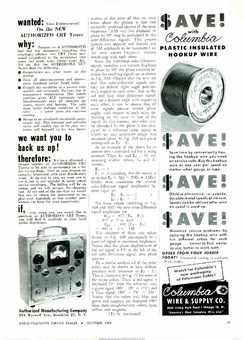
wanted. Your Endorsement!
On the NEW AUTHORIZED CRT Tester
Because we at AUTHORIZED feel that our statements regarding this amazingly efficient new CRT Tester may sound prejudiced to the serviceman who hears and reads many claims every day. We say that the AUTHORIZED CRT Tester does the following:
Outperforms any other tester on the market. Tests all electromagnetic and electro- static duodecal socket based tubes. Reveals the condition of a picture tube quickly and accurately. No time lost in unnecessary computation. One switch position gives ALL continuity tests! Simultaneously tests all elements for opens, shorts and leakage. The split neon bulbs indicate condition of the tube . . . a meter gives the emission reading. Serves as an absolutely invaluable point - of -sale tool. This compact and portable tester will enable you to let your cus- tomer sell himself in his own home.
why
we want you to
back us up!
therefore. We have allocated a
certain number of AUTHORIZED CRT Testers to be sent to servicemen on a ten day try -out basis. Send us your request on company letterhead, with your distributor's name. At no cost to you, we want you to use it, test it, and appraise it, under actual service conditions. The billing will be on memo, and we will pre -pay the shipping cost. At the end of the ten days we would like you to return the instrument to us, plus your appraisal, so that another serv- iceman can have the same opportunity.
if after using one, you would like to purchase an AUTHORIZED CRT Tester, you will find it available at your local jobber -distributor.
emir
Authorized Manufacturing Company 919 Wyckoff Ave., Brookb n 27, N. Y.
section; at this point all that we must know about the process is that two artificially produced carriers of the same frequency (3.58 mc) but displaced in phase by 90° may be modulated by the color -difference signals. This process permits two separate and distinct sets of AM sidebands to be transmitted on the same carrier frequency without interfering with each other.
Since the individual color -difference signals modulate two carriers displaced in phase by 90° the phase relations be- tween the resulting signals are as shown in Fig. 10A. Observe that the new red and blue color -difference signals now take up definite right angle positions with respect to each other. Just as the red and blue color difference signals take up a definite angle with respect to
each other, it can be shown that all color signals assume certain phase angles with respect to each other de- pending on the color or hue of the signal. In this manner, any color may be identified by the phase it has com- pared to a reference color signal to which we may arbitrarily assign zero reference phase. In Fig. 10A zero phase corresponds to ER - Ey.
As an example of the above let us assume that a saturated red bar is being scanned. Then, Eo and Ea = O; and assuming relative values, Ea and E, become:
ER = 1
EY = .3 (recalling that the matrix is
set so that Er = .3ER + .59E0 .11ER). Under these conditions the relative color -difference signal amplitudes be- come equal to:
En-Er=-.3 E - Er = .7
For these values (referring to Fig. 10A and IOB) the new color -difference signal amplitudes are:
Rcn = .877 (ER - Er) =.877 x.7=.614
Bcn = .493 (ER - Ex) = .493 x -.3 = -.148 The resultant of these two values
shown in Fig. 1013 corresponds to a pure red signal of maximum brightness. Notice that the phase displacement of the red signal is 13° to the left of the red color -difference signal zero phase position.
By a similar analysis all of the other colors may be shown to have definite positions with reference to ER - E. This is illustrated in Fig. 11 for some of the major colors. Thus, a red signal is displaced 13° from the reference axis; a green signal 180° - 29° = 151°; and a blue signal 180° - 79° = 101°. Notice that the colors red, blue and green and magenta are displaced 180° from their complementary colors, cyan, yellow and magenta.
[To be continued]
III AV E ! with
PLASTIC INSULATED HOOKUP WIRE
llAVE! Save time by conveniently hav- ing the hookup wire you need on service calls. Buy this hookup wire at one cost per spool no matter what gauge or type.
$AVE! Obtain attractive, re -usable, durable metal spools at no cost. Spools can be utilized after wire on spool is used up.
$AVE! Minimize service problems by carrying the hookup wire with ten different colors for each gauge ... easier to find, easier to use, better to work with.
ORDER FROM YOUR JOBBER TODAY! Illustrated catalog i-. .n ailable. u'ritc today.
1 Watch for Columbia's new packaging
I of Television Cable!
2850 Irving Park Road Chicago 18, III.
"America's Most Complete Wire Line"
RADIO -TELEVISION SERVICE DEALER OCTOBER, 1954 63
www.americanradiohistory.com

04%. E/CO FLYBACK & YOKE
TESTER KIT
MODEL
944
Checks all flybacks & yokes instantly-in or out of set!
Detects even 1 shorted turni Exclusive separate calibration for air F. iron -core flybacks for accurate testing of all types. Tests continuity of coils, speakers, switches, etc.
large 41/2" meter, 3 colored scales.
Complete with easy Instructions. Compact, rugged, smartly styled. See It at your jobber today. Write for FREE Catalog o-10 describing EIOO's 38 Kits and 42 Wired Instruments. Prices 5% tigher or West Coast.
,EICO
r
LOWEST
PRICED
KIT
$ 23.9 5 Wired $34.95
ELECTRONIC INSTRUMENT CO., Inc. 34 Withers Street, Brooklyn, N. Y.
©54
Send for it
1955 308 -PAGE
Everything in Electronics For Service Technicians and Engineers
Get the complete, up-to-date 1955 ALLIED Catalog. It's packed with the world's largest selection of TV and radio parts and accessories, test in- struments, Hi-Fi systems and compo- nents. P. A. systems, tubes, tools- everything for service work and indus- trial electronic application. Depend on ALLIED for fast shipment from the world's largest stocks- save time and money. Send today for your FREE 308 -
page ALLIED Catalog.
ALLIED RADIO CORP., Dept. 26-K-4 100 N. Western Ave., Chicago 80, III.
Send FREE 1955 ALLIED Catalog
Name
Address
L City
1
Zone _ State _ ,
Advertising Index
Acme Electric Corp 59
Aerovox Corporation 61
Allied Radio Corp 64
American Scientific Development Co 61
Authorized Manufacturing Co 63
Belden Manufacturing Co 19
Blonder -Tongue Laboratories, Inc 20
Bussmann Manufacturing Co 36
CBS-Hytron 17
Channel Master Corp 2, 3
Chicago Standard Transformer Corp...57
Clear Beam Antenna Corp 56
Columbia Wire & Supply Co 63
Crosley Div., Avco Mfg. Co 13
Electronic Instrument Co., Inc. (EICO) 64
General Cement Mfg. Co. 62
Hycon Mfg. Co 18
Jensen Industries 64
Jensen Manufacturing Co 6
JFD Manufacturing Co., Inc 7
Merit Coil & Transformer Corp 4
Ohmite Manufacturing Co 52
Oxford Electric Corp 64
Philco Corporation 24, 25
Precision Apparatus Co., Inc Cover 3
Radiant Corporation 49
Radio City Products Co., Inc 9
Raytheon Manufacturing Co 8
RCA Batteries Cover 4
Rider, John F. Publisher 53, 58
Sams, Howard W. & Co 60
Sangamo Electric Company 20
Simpson Electric Company 31
Snyder Manufacturing Co Cover 2
Sylvania Electric Products Inc 33
Trio Manufacturing Co 21
Tung -Sol Electric, Inc 54, 55
University Loudspeakers, Inc 12
Walco 60
Walsco Electronics Corp 26
Weston Elec. Instrument Corp 51
"Since I got this Hi-Fi rig with a JENSEN NEEDLE,
business is jumping.
Preferred for Original Equipment
Proven for Replacement
X 1J
Q
Speakers
s
Available from leading jobbers!
OXFORD ELECTRIC CORP. 391 1 S. Michigan Ave., Chicago 15, III.
EXPORT: ROBURN AGENCIES, N.Y.C., N.Y.
In Canada: Atlas Radio Corp., Ltd., Toronto
64 RADIO -TELEVISION SERVICE DEALER OCTOBER, 1954
www.americanradiohistory.com
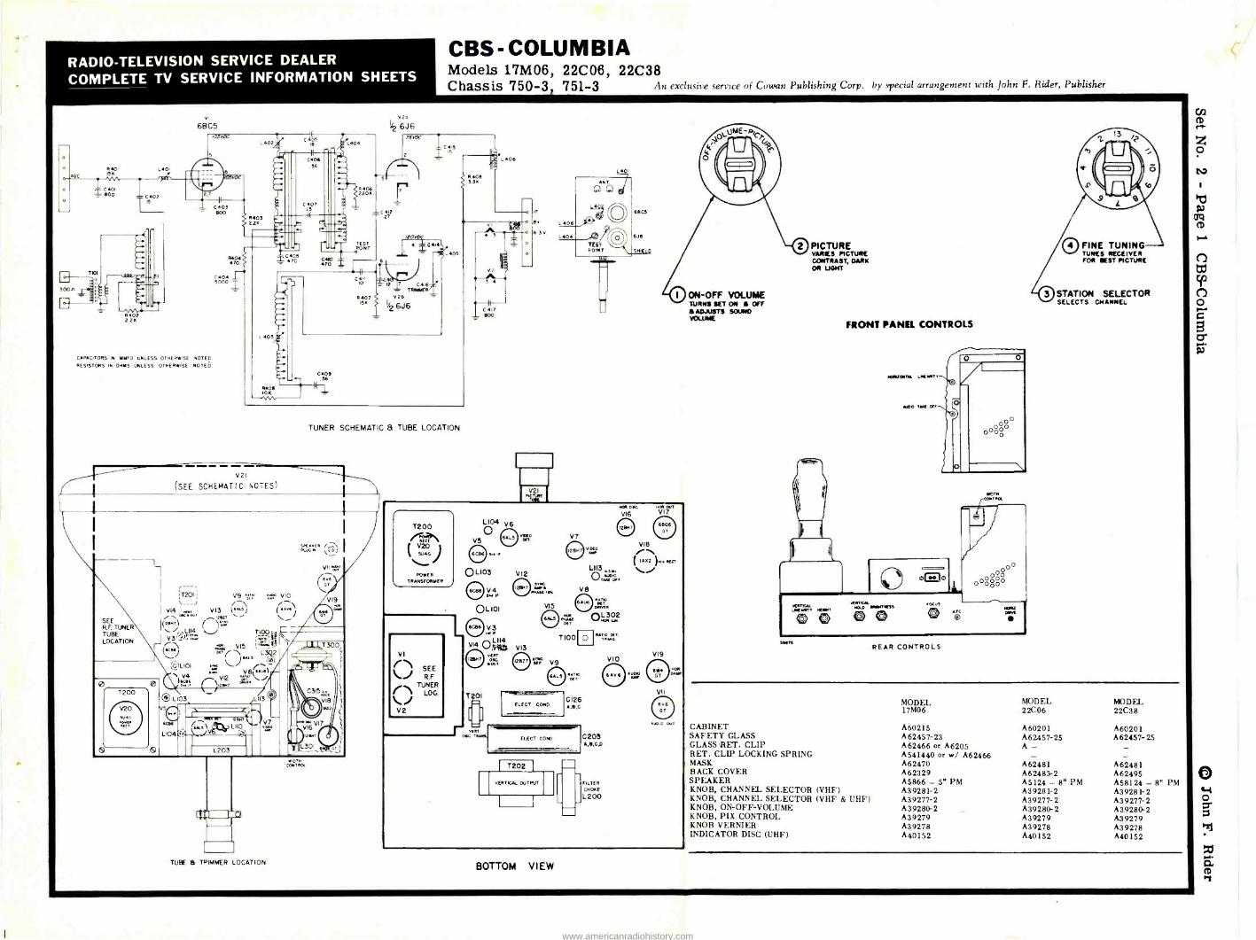
RADIO -TELEVISION SERVICE DEALER COMPLETE TV SERVICE INFORMATION SHEETS
CBS -COLUMBIA Models 17M06, 22C06, 22C38 Chassis 750-3 751-3 An exclusive service of Cowan Publishing Corp. by special arrangement with John F. Rider, Publisher
Tal
300'
R402 226
vI
6BC5
C403 - /00
[ 1403 22K
CAPACITORS IN OWED UNLESS OTHERWISE NOTED
RESISTORS IN OHMS UNLESS OTHERWISE NOTED
V2I
(SEE SCHEMATIC (TOTES)
L 403
R40/ ION
L404
220K
TEST é OINT
C4lI IO
R40 15K
C401 .56
V2a
142 6J6 15HX
-C412 .27
12 C416 TRIMMER
V20
1/2 6J6
4
405
TUNER SCHEMATIC & TUBE LOCATION
SEE RF TUNER TUBE LOCATION
G
L 03
V9 uO'0 VIO
V13 (` %O ( s zn \
( 1= \ T100¢V
VI5 r\1 L3Q2 / wu 11ê+)
\ .1tMT
SPUTR W
/?i FLUG
V
.04
L104
eiT
. 74.7 Nv LtepL110
L203
7
WIDTH CONTROL
TUBE e TP.IMMER LOCATION
IF
6 L406 6.3V
L404
V21 "far
L401
6E105
6J6
SHIEL
POWER TRANSFORMER
VI
`71 SEE \ R.F.
0L103
O4
OL 101
L VI4
LII4 Ritt
TENT 066. WT
T201
V12
V13
V7
°: MAE{ 1111
vwbo
V8
H06 o4c.
VI6
L113 Auao
TAR OFI
Rp .T1RvéR
6ALs .HA.. OL302
oET
T100 n 4A::.ósT VIS
ELECT CONO
f 7202
VERTICAL OUTPUT
C126 6,I,C
C203 A,I,Cp
FILTER CHORE
L200
VIO
VI8
NON OUT
VI7
V19
A.. OUT
BOTTOM VIEW
ON-OFF VOLUME TURNS SET ON IN Off
ADJUSTS SOUND VOLUME
PICTURE VARIES PICTURE CONTRAST,DARK OR UGHT
FRONT PANEL CONTROLS
O
úi.11`T HEWN, 0 0 ,SITKJL
N6LD MweRlS 0 0 FOCUS
®° r< O
at. <P1TRQ
00 0 000
00000
NT REAR CONTROLS
0 FINE TUNING TUNES RECEIVER FOR @EST PICTURE
STATION SELECTOR SELECTS CHANNEL
MODEL MODEL MODEL 17M06 22C06 22C38
CABINET A60215 A60201 A60201 SAFETY GLASS A62457-23 A62457-25 A62457-25 GLASS RET. CLIP A62466 or A6205 A - - RET. CLIP LOCKING SPRING A541440 or w/ A62466 - - MASK A62470 A62481 A62481 BACK COVER A62329 A62483-2 A62495 SPEAKER A5866 - 5" PM A5124 - 8" PM A58124 - 8" PM KNOB, CHANNEL SELECTOR (VHF) A39281-2 A39281-2 A39281-2 KNOB, CHANNEL SELECTOR (VHF & UHF) A39277-2 A39277-2 A39277-2 KNOB, ON -OFF -VOLUME A39280-2 A39280-2 A39280.2 KNOB, PIX CONTROL A39279 A39279 A39279 KNOB VERNIER A39278 A39278 A39278 INDICATOR DISC (UHF) A40152 A40152 A40152
o
www.americanradiohistory.com

RADIO -TELEVISION SERVICE DEALER COMPLETE TV SERVICE INFORMATION SHEETS
CBS -COLUMBIA Models 17M06, 22C06, 22C38 Chassis 750-3, 751-3 An exclusive service of Cowan Publishing Corp. by special arrangement with John F. Rider, Publisher
TELEVISION ALIGNMENT PROCEDURE
Aligning a television receiver is an exacting pro- cedure and involves the use of bench space, test equip- ment and skilled personnel at the service shop, as well as the cost of making two trips to the customer's home. Be- fore deciding that the chassis must be pulled and aligned at the shop, the serviceman should check these very common sources of trouble:
1 - The antenna and installation.
2 - Front panel and rear chassis controls, including picutre tube adjustments.
3 - Reception on all available channels.
4 - Tube failures. Substitute from your kit of known good replacements.
5 - Visual inspection of underside of chassis for obvious faults, such as loose connections, etc.
TEST EQUIPMENT REQUIRED FOR ALIGNMENT
The equipment specified below is desirable, but in cases where this equipment is not available, it is possible to align the receiver by use of a 20 to 30 mc. modulated r -f signal generator, using the picture and speaker as in- dication of alignment.
I - Signal Generator with an output variable between 100 and 100,000 microvolts, and crystal con- trolled or crystal -calibrated at the following frequencies:
a- 4.5 megacycles
b- 22.8 megacycles
c- 25.4 megacycles
d- 21.25 megacycles
2 - DC Vacuum Tube Voltmeter with 5 volt and 10 volt scales.
3 -A pair of balanced (± 1%) 100K carbon resisters.
TEST EQUIPMENT
REQUIRED FOR SWEEP ALIGNMENT CHECK
1 -R -F sweep generator with frequencies ranging from 40 to 220 megacycles, having sweep width of approximately 10 megacycles, and having ad- justable output to approximately 0.1 volt.
2 - Crystal -controlled or crystal -calibrated markers for the picture and sound carriers of each channel.
3 - Cathode Ray Oscilloscope with good low fre- quency response.
CAUTION: THE SECOND ANODE LEAD TO THE PIC- TURE TUBE HAS A HIGH POTENTIAL. DURING THIS ALIGNMENT IT IS ADVISABLE TO REMOVE THE HORI- ZONTAL OUTPUT TUBE FROM ITS SOCKET, THUS ELIMINATING THIS HIGH VOLTAGE HAZARD.
I.F. ALIGNMENT PROCEDURE
1 - Connect "high" lead of signal generator to the test point located on the top of the RF tuner unit (Refer to the R -F tuner location diagram located on inside of cabinet). Connect ground to chassis.
2 - Connect DC VTVM lead (through 10K isolating resistor) to 4.7K diode loaf resistor (R113); ground to chassis. Set VTVM to 5 volt scale, negative polarity.
3 - Set I.F. generator to 25.4 megacycles with suf- ficient output to read approximately 3 volts on the VTVM.
4 - Carefully adjust L101 and L104 (see tube and tuner location) for maximum deflection on VTVM. Adjust sweep generator output to keep meter reading approximately 3 volts.
5 - Set I.F..signal generator to 22.8 megacycles with sufficient output to read approximately 3 volts on the VTVM.,
6 - Carefully adjust L406, L103 (see tube and tuner location) for maximum deflection on VTVM. Ad- just signal generator output to keep meter read- ing approximately 3 volta.
7 - Set I.F. signal generator to 21.25 megacycles, set VTVM to 10 volt scale (negative polarity), and adjust signal generator output for conven- ient deflection on VTVM.
8 - Adjust L114 for minimum deflection on VTVM.
SWEEP ALIGNMENT CHECK
Although not essential, a sweep alignment check is a desirable verification of good R -F and 1.F. response. Pro- ceed as follows:
1 - Connect R -F sweep generator to antenna ter- minals (antenna impedance 300 ohms.)
2 - Calibrate oscilloscope for convenient 5 volts peak -to -peak vertical deflection (5 volts peak - to -peak is approximately 1/4 of the peak -to -peak voltage of the 6.3V A.C. filament).
3 - Connect vertical input of oscilloscope (through 10K isolating resistor) to 4.7 diode load resistor (R 113); -ground to chassis. Connect horizontal in- put of oscilloscope to scope terminals of R -F generator; adjust for convenient horizontal sweep.
4 - Set R -F sweep generator to channel 3, television receiver to channel 3, and if necessary, adjust sweep generator output, sweep width, and scope horizontal setting for convenient band-pass dis- play having 5 volts vertical deflection as pre- viously calibrated. (If you must touch scope ver tical settings during these adjustments recali - brate scope for 5 volts peak -to -peak as in step 2
above).
5 - Couple crystal -controlled R -F carrier markers very loosely to antenna terminals, adjust receiver FINE TUNING control till video carrier marker is 1/2 down on curve. Turn up marker output till R -f sound carrier is visible on bandpasa and ad- just sound trap (L 114) to minimize effect of sound carrier marker.
6 - Check all channels as above.
SOUND ALIGNMENT
1 - Connect 4.5 megacycle signal generator to pin 2 of 12BH7 (V7) video amplifier.
2 - Connect DC V.T.V.M. lead to pin 7 of 6AL5 (V9) ratio detector, negative polarity.
3 - Adjust signal generator to precisely 4.5 mega- cycles; adjust output to read approximately 5 volts on V.T.V.M.
4 - Adjust L113 and bottom of T100 for maximum de- flection on V.T.V.M. Keep V.T.V.M. reading be -
1 low 10 volts at all times.
5 - Attach two series -connected IOOK( ± 1%) resistors across R 126 (Ratio Detector Load Resistor). Con- nect DC V.T.V.M. to center -tap of 100K resistors, and connect ground wire of V.T.V.M. to junction of C119 and C120 (Audio Take -Off of T100).
6 - Adjust top of T100 for zero reading on V.T.V.M. between a plus and a minus peak.
VIDEO AMPLIFIER TRAP
When necessary, the video amplifier 4.5 mc trap (L110) should be adjusted as follows:
1 - Connect 4.5 mc signal generator "high" lead to picture tube grid; ground to chassis.
2 - Connect DC V.T.V.M. to pin 7 of 6AL5 (V9) ratio detector, 10 volt scale, negative polarity.
3 - Adjust L110 for minimum deflection on V.T.V.M.
R -F OSCILLATOR
If all channels are not within range of FINE TUNING control, adjust two screws located in front of r -f tuner unit for adjustment of either low or high band. CAUTION: Do not touch adjustments on top of r -f tuner unit, other than converter plate coil, L404, during IF Alignment.
HORIZONTAL OSCILLATOR ALIGNMENT
If the Horizontal Hold control fails to maintain sync, the horizontal oscillator should' be reset. To reset this screwdriver adjustment, set the horizontal hold control in
the center of its range and sync the picture with the hori- zontal A.F.C. adjustment screw. Check the hold control action on various channels and alter the screw adjustment as required to provide sync on all channels.
50%
_L 25.75MC
_L_ NOT GREATER THAN 30%
21.25MC
VIDEO SOUND CARRIER CARRIER
IDEAL SANDPASS
DEFLECTION YOKE, ION TRAP AND FOCUS ADJUSTMENT
Following is the proper procedure for adjusting the Deflection Yoke, len Trap and Focus.
The receiver should be turned on but not connected to an antenna. These steps should then be taken in the following order:
1 - The Deflection Yoke should be moved as far forward as possible on the neck of the CRT.
2 - The Brightness control should be turned to max- imum (clockwise) and the Contrast control should be turned to minimum (counterclockwise).
3 - The Ion Trap should be rotated and at the same time moved forward and backward to find the position which produces the brightest raster on screen.
4 - The Deflection Yoke should be rotated so that the top and bottom edges of the raster are parallel to the top of the chassis.
5 - The Brightness control should now be reduced (ccw) to a point where the raster is slightly above normal brilliance.
6 - With Brightness and Contrast controls at normal positions, adjust the Focus control (rear of chassis) for well-defined scanning lines.
HEIGHT, WIDTH AND LINEARITY
To adjust the overall size and linearity of the picture it is almost mandatory that a test pattern transmitted from a
local station be used. It should also be remembered that in areas where more than one station is being received, that pictures transmitted from different stations will vary slight- ly in size. The smallest transmitted picture should be made to fill the area outlined by the mask.
The Width control (rear of H.V. cage) should be ad- justed to give a picture that will fill the mask horizontally.
The Height and Vertical Linearity controls (both rear of chassis) should then be adjusted for a linear picture that will fill the mask vertically.
PICTURE TUBE HANDLING PRECAUTIONS
Tho plcrra tuba encloses a high vacuum and with the large surface area of gloss involved, the stressas sat
up, particularly at the front rim of the tube, ore con- siderable. An abnormal handling stress, occidental blow at a highly stressed surface, or ven o scratch on the surface of the tubs could cause it to implode or collapse with destructive vielsnce.
HIGH VOLTAGE WARNING
Operation of this receiver outside the cabinet or with covers removed Involves a shock hazard from the re- celwr power supplies. Work on the receiver should not be attempted by anyone who Is not thoroughly familiar with the precautions necessary when working on high voltage equipment.
www.americanradiohistory.com

RADIO -TELEVISION SERVICE DEALER COMPLETE TV SERVICE INFORMATION SHEETS
CBS - COLUMBIA Models 17M06, 22C06, 22C38
An exclusive service of Cowan Publishing Corp. by special arrangement with John F. Rider, Publisher Chassis 750-3. 751-3
RESISTORS
SCHEM. LOC. CHASSIS* PART NO. DESCRIPTION
SCHEM. LOC. CHASSIS
R100 PE231-1163 Carbon, 3900 Ohm 1/2W ±107. C100 R101 PE231-1113 Carbon, 33 Ohm 1/2W 210% C101 R102 PE.231-1137 Carbon. 330 Ohm 1/2W 2107. R103 PE231-1179 Carban,18K ohm 1/2w ±10% C102 R104 PE231-1117 Carbon, 47 Ohm 1/2W ±107. R105 PE231-1123 Carbon, 82 Ohm 1/2W I LOT. C103 R106 PE231-1167 Carbon,5600 ohm 1/2w ±10% C104 R107 PE231-1133 Carbon, 220 Ohm 1/2W 1107. C105 R108 PE231-1133 Carbon, 220 Ohm 1/26 ±107. R109 PE231-1129 Carbon, 150 Ohm 1/2W 2107. C106 R110 PE231-1197 Carbon, 100k Ohm 1/2W 2107. C107 Riti PE231-1177 Carbon, 15k Ohm 1/2W ±107. R112 C108 R113 R114
PE23I-1165 PE231-1133
Carbon, 4700 Ohm 1/2W ±107. Carbon, 220 Ohm 1/2W ±107. C 109
C110 R115 PE231-1165 Carbon, 47000hm 1/2W ±I07. R116 PE232-1161 Carbon, 3300 Ohm 1W ±10% C111 R117 PE231-1221 Carbon, 1.0 Megohm 1/2W ±107 R118 PE231-1131 Carbon, 180 Ohm 1/2W ±107. C112 R119 C113 R120 PE233-74 Carbon, Ilk Ohm 2W YS% R121 R122
PE233-1179 PE231-1173
Carbon, 18k Ohm 26 ±107. Carbon, 10k Ohm 1/2W ±107. C 114
R123 R124
PE231-1197 PE231-1197
Carbon, 100k Ohm 1/2W 1/2W±107. Carbon, 100k Ohm 1/2W ±107. C11S
R125 R126
PE231-1155 PE231-1189
Carbon, 1800 Ohm 1 /2 W ±107. Carbon, 47k Ohm 1/2W ±107. C116
R127 PE231-1245 Carbon, 10 Megohm 1/2W ±107. C117 R128 R129
PE231-1213 PE231'1213
Carbon, 470k Ohm 1/2W ±107. Carbnn, 470k Ohm 1 /2W ±107. CIl8
R130 PE232-1137 Carbon, 330 Ohm 1W ±i '. C119 R131 PC21134-4 Wirewound, 3250 Ohm 7W t 107. R136 PE231-1173 Carbon, 10k Ohm 1/2W ±107. R139 PE231-1215 Carbon,560K ohm 1/2w ±107. C 120 R140 PE231-1187 Carbon, 39K ohm I/2w ±107. C121 R200 R201
PE23151 PC21134-2
Wirewound, 1.2 Ohm 1W ±10% Wirewound, 60 Ohm l OW ±107.
0122 C123 R202 PE231-1183 Carbon, 27k Ohm 1/2W ±107. C 124
R203 R204 R205
PE231-1175 PE231-1193 PE231-1213
Carbon, 12k Ohm 1/2W Y 10% Carbon, 68k Ohm I/2W ± 107. Carbon, 470k Ohm 1 /2W ±107.
C 125 C126
R206 R207 R208
PE23I-1229 PE231-1229 PE232-1181
Carbon, 2.2 Megohm 1 /2W ±107. Carbon, 2.2 Megohm 1/2W ±10% Carbon, 22k Ohm 1W±I07
C127 C 128
R209 R210 R211
PE231-1221 oE231-1171 PE231-1181
Carbon, 1.0 Megohm 1/2W ±10% Carbon, 8200 Ohm 1/2W ±107. Carbon, 22k Ohm 1/2W ±107.
C129 C132
R212 PE231-1221 Carbon, 1.0 Megohm 1/2W±107. C 133
R213 R214 R215
PE231-1159 PE231-1163 PE231-1163
Carbon, 2700 Ohm 1/2W ±107. Carbon, 3900 Ohm 1/2W ±10% Carbon, 3900 Ohm 1/2W ±107.
C201 C202
R217 R218
PE231-1169 PE232-127
Carbon, 6800 Ohm 1/2W ±107 Carbon, 1.8 Megohm 1W ±5% C203
R219 R220
PE231-1189 PE231-1213
Carbon, 47k Ohm 1/2W ±107. Carbon, 470k Ohm 1/2W 2107. C204
R221 R222
PE231-1225 PE231-1155
Carbon, 1.5 Megohm 1 /2W ±107. Carbon, 1800 Ohm 1/2W ±I07. C205
R225 R226
PE233-1161 PE233-1161
Carbon, 3300 Ohm 2W ±10% Carbon, 3300 Ohm 2W ±10% C206
R227 R228 R229 R230 R231 R232 R233 R234
PE231-1229 PE231-1185 PE231-1207 PE231-1221 PE231-1181 PE231-1181 PE231-1171 PE231-1189
Carbon, 2.2 Megohm 1/2W ±107. Carbon, 33k Ohm 1/2W ±107. Carbon, 270k Ohm 1/2W ±10% Carbon, 1.0 Megohm 1 /2W ±10% Carbon, 22k Ohm 1/2W ±107. Carbon, 22k Ohm 1/2W ±107. Carbon, 8200 Ohm 1/26± 107. Carbon, 47k Ohm 1/2W ±107.
C207 C208 C209 C210 C211 C212 C213
R236 PE232-1205 Carbon, 220K ohm lw ±107. C214 R300 PC21134-16 Wirewound, 2250 Ohm 15W 3107 C215 R301 PE233-1165 Carbon, 4 700 Ohm 29/ ±107. C216 R302 RE233-1169 Carbon, 6800 Ohm 2W ±107. R303 PE231-1197 Carbon, 1OOk Ohm 1/2W ±107. C218 R304 PE231-1197 Carbon, 100k Ohm 1/2W ±107. R305 PE231-1213 Carbon,470k Ohm 1/2W±107. C219 R306 PE231-1233 Carbon, 3.3 Megohm 1/2W ±107. C220 R307 PE232-1181 Carbon, 22k Ohm IW ±10% C221 R308 PE231-1167 Carbon, 5600 Ohm 1/2W±107. R309 PE231-1155 Carbon, 1800 Ohm l/2W ±107. C222 R310 PE231-1205 Carbon, 220k Ohm 1/2W ±10% R311 PE231-1213 Carbon, 470k Ohm 1 /26 Y 107. C223 R312 PE231-1197 Carbon, 100k Ohm 1/2W ±107. 0227 R313 PE231-1123 Carbon. 82 Ohm 1/2W ± I0% R314 PE233-1133 Carbon, 220 Ohm 2W ±107. C300 R315 PE23163 Carbon, 0.560hm 1/2W ±10% C301 R316 751-3 PE233-2321 Carbon, 1.0 Megohm 26 ±207. C302
(Allen Bradley) R317 750-3 PE231-1171 Carbon, 8200 Ohm 1/2W ±107. C303 R318 PE232-1177 Carbon, 15k Ohm 1W±107. R319 750-3 PE231-1109 Carbon, 22 Ohm 1/2W Y I0% C304 R319 751-3 PE231-1117 Carbon, 47 Ohm 1/2W ±107. C305 R320 751-3 PE233-1165 Carbón, 4700 Ohm 2W ±107.
CAPACITORS
PART NO. DESCRIPTION
PE 190-133 Mica, 270mmf 500V ±107. PA19147 Ceramic, Shielded Dual
Disc, 1500nmf GMV PE556-234 Ceramic Tubular,680nmf
350V ±10% (Insul.) PE 190-133 Mica, 270mmf 500V '1107. PE190-133 Mica, 270mmf 500V ±107. PA19148 Ceramic, Single Disc
1500mmf GMV PA20138 Electrolytic, lmfd 50V PP 19163 Ceramic, Shielded Dual
Disc 5000nmf GMV PE190-140 Mica, 510mmf 500V ±107. PE 190- 107 Mica, 22mmf 500V ±10% PE555-101 Ceramic Tubular lOmmf.
500V ±20% (Unins.) PE555-136 Ceramic Tubular 1000mmf
350V ±20% (Unira.) PE194-160 Paper, .05mfd600V ±207. PP 19201 Ceramic Tubular, 820mmf
350V ±107. (Unins.) PE555-100 Ceramic Tubule:, 5mml
500V ±10% (Unina.) PE555-113-2 Ceramic Tubular,47mmf
500V ±207. NPO PE197-160 Molded Tubular .05mfd
600V ±207. PE194-151 Power, .005mfd600V±20% PA19148 Ceramic Single Disc
1500mmf GMV PE556-236 Ceramic Tubular,
PE 194-160 PA 620181 PE194-156 PE 194-160 PE194-145 PE194-151 PA20135
PE 194-145 PESSS-100
PA20182 PE 194-145 PE556-136
100ommf 350V ±107. (maul.)
Paper, .05mfd 600V ±20%
Electrolytic, lmfd 100V Paper. .02mfd 600V ±207. Paper, .05mfd 600V ±207. Paper, .001mfd 600V ±209. Paper, .005mfd 600V.±20% Electrolytic, 10-10-10
mfd 450V Paper, .001mfd 600V 1407 Ceramic, 5.0mmf 500V
±107. (Uninsul.) Electrolytic, 50mfd 25V Paper, .001mfd 600V ±207. Ceramic Tubular, 1500mmf
350V ±207. (maul.)
PA19109 Ceramic, Single Disc 5000mmf GMV
PA20144 Electrolytic, 40-40-20-20-mfd 450V
PA19(09 Ceramic, Single Disc 5000mmf GMV
PA19109 Ceramic,Singie Disc S000mmf GMV
PA19109 Ceramic, Single Disc 5000mmf GMV
PE 194-156 Paper, .02mfd 600V ±20% PE 190-137 Mica, 390mmf 500V ±107. PE190-133 Mica, 270mmf SOOV ±107. PE 194-155 Paper, .01mfd 600V ±20% PE 194-155 Papar, .01mfd 600V ±207. PE192-163 Mica, 4700mmf 500V±107. PEI 94-159 Paper, .035mfd 600V
±207. PE 194-156 Paper, .02mfd 600V ±207. PE 194-160 Paper..05mid 600V ±207. PA20174 Electrolytic, 5mfd 350V
(Non -Polarized) PE194-160 Paper, .05m/d600V±207. PE 194-160 Paper, .OSmfd 600V ±207 PE194-1SS Paper, .Olmld 600V ±207. PE 194-151 Papar, .005mfd 600V
±20% PE194-151 Paper, .00Smfd 600V
±207. PE194-155 pager,.01mtd600V t207. PA19109 Ceramlc,Single Disc
5000mmf GMV PE194-145 Peper,.00lmtd600V±207. PE 194-145 Papar, .001mfd 600V±207. PE197-151 Molded Tubular .005mfd
600V ±207 PE 197-151 Molded Tubular .005mfd
600V ±207. PE 194-160 Paper, .05mfd 600V ±20% PE 195-261 Mica, Silver, 3900mnf
500V ±57.
CAPACITORS
SC HEM. LOC. CHASSIS PART NO. DESCRIPTION
C31/6 P.e 1 VU- 1J/ Sucs, .i9Vmmt 500V Ito'h C307 PE 190-133 Mica, 270mmf 500V ±10% C308 750-3 PE190-125 Mica, 120mmt 500V ±107. C308 751-3 PE190-137 Mica, 390mmf 500V ±107, C309 PA1772 Trimmer, 25-280mmf C310 PA20137 Electrolytic, lOmtd 25V C311 751-3 PP19145 Mica, Smmf 2500V GMV C312 PE197-160 Molded Tubular .05mfd
600V ±20% C313 751-3 PP19146 Mica, 1Ommf 2500V GMV C314 PE197-160 Molded Tubular .05mfd
600V ±20% C31S 751-3 PA 1998-3 Ceramic, S00rmf 20kv C316 PE 197-162 Molded Tubular .lmfd
600V ±207. C317 PÁ20147 Electrolytic 25mfd 12V C318 PP 19180 Mica, 220mmf 1000V ±10% C320 750-3 PE 190-133 Mica, 270mmf 500V ±107
CHOKES & COILS SCHEM.
LOC. CHASSIS PART NO. DESCRIPTION A3392 Coil, Pi: IF A28253 Choke, RF A3392 Coil, Pi: IF A3392 Coll, Piz IF A28253 Choke, RF A28255-2 Coll, Peaking (White) A282S5-1 Coil,Peaking (Red) A28255-2 Coil, Peaking (White) A28255-1 Coll. Peaking (Red) A28286 Coil, 4.5 MC. Trap A28255-1 Coil, Peaking (Red) A28255-4 Coli,Peaking (Green) A28286 Coll, 4.5 MC Audio
Take off Coll, 21.25 MC IF Trap Coil, Filter Choke Choke, Filament Choke, Filament Coil, Deflection Yoke Coil, Deflection Yoke Coil, Horiz. Freq. Control Coli,Width Control Coil, Width Control Coll, Horiz. Linearity Deflection Yoke Cover
w/Centering Device
L 101 L 102 L103 L 104 L 105 L 106 L 107 L108 L 109 L110 L111 L112 L 113
L1f4 L200 L201 L202 L203 750-3 L203 751-3 L300 L301 750-3 L301 751-3 L302
A28314 A 140 6 A28276 A28276 A28328 A28330 A28263 A28279-1 A283 18-1 A28292 A28331
TRANSFORMERS SC HEM.
LOC. CHASSIS PART NO. DESCRIPTION
T 100 Ratio Detector
T200 T201 T202
T300
A1201 or 1202
A10109 A10106 A10152-1 A10136 or A10137
Power Vertical Oscillator Vertical Output
Horizontal Output
CONTROLS SCHEM.
LOC. CHASSIS PART NO. DESCRIPTION
P100
P200 P201 P202
P294 P206
A24142 Contrast -Volume, 5K -210K ohm
A24112 Vertical Hold, 1.0 Megohm A24111 Vertical Size, 5.0 Megohm A24114 Vertical Linearity,
3K ohm Wirewound A24110 Brightness, 100K ohm A24112 Focus Control, 1.OMegohrr
Used on all chassie unless otherwise specified in this column. If specified, the part is used only on the chassie indicated.
MISC. CHASSIS ACCESS. 8t PARTS - ALL CHASSIS
PART NO. DESCRIPTION
A 65100K A5355 A5356 A54609 A541059 A541242 A540-62 A540-67 A540-44 A 540-19 A540-34 A1815S A18210 A18173 A 18171 A18157 A18147 A 18101 A541131 A562-6 A562-3 A54618-1 A3206 A541341
Chassie Shield, H.V. Supply Cover, H.V. Supply Shield Bracket, Horiz. Freq. Control Coil Bracket. Interlock Grounding Spring CRT Coating Terminal Strip, AAEAAAEAA Terminal -Strip, AAAEAA Terminal Strip, AAEAA Terminal Strip, AEA Terminal Strip, AAEA Socket, Octal Moulded Socket, Octal Moulded Bakelite Saddle Socket, 9 Pin Moulded Socket, 9 Pin Moulded No Saddle Socket, 9 Pin Wafer Socket, 7 Pin Wafer Socket, Speaker -Plug Socket, H.V. Cond. Capacitor Clips; 1-3/8 Capacitor Clips; 3/4 Tube Shield Ion Trap Anode Lead Holder
MISC. CHASSIS ACCESS. & PARTS - 17" TUBE
PART NO. DESCRIPTION
A54851 Bracket, Yoke Hood as Support A541084-1 Channel. CRT Front Support; Left A541084-2 Channel, CRT Front Support; Right A54827 Strap, CRT; Right A54828 Strap, CRT; Left A541086 Bracket, CRT Stop A5514 1- I Anode Connector Assembly A541085 Cushion, Rubber; CRT Channel A541110-2 Cushion, Sponge Rubber; CRT Strap, Right A541110-1 Cushion, Sponge Rubber; CRT Strap, Left A54971-18 Cushion, Cork; CRT Stop Bkt. A18197-3 Socket, Kinescope
MISC. CHASSIS ACCESS. es PARTS - 21" CHASSIS
PART NO.
A541251 A541248-1 A5412442 A541000 A541246 A541250-1 A541280-2 A54 1383
DESCRIPTION Bracket, Interlock Bracket, CRT Rear Support (Left) Cracket, CRT Rear Support (Right)
RT Rubber Grommet Bracket, Yoke Hood and CRT Grommet Bracket, Yoke Hood Support (Left) Bracket, Yoke Hood Support (Right) Bracket, CRT Front Support and Stop
AS41249 Bracket, Tie Rod AS41254 CRT Strap Assembly A541261-1 Rubber Cushion (CRT Front Support and
Stop Bkt.) A541261-2 Rubber Cushion (CRT Front Support and
Stop Bkt.) A541102-6 Rubber Cushion (CRT Strap)
www.americanradiohistory.com

o
RADIO -TELEVISION SERVICE DEALER COMPLETE TV SERVICE INFORMATION SHEETS
CBS -COLUMBIA Models 17M06, 22C06, 22C38 Chassis 750-3 751-3 An exclusive service of Cowan Publishing Corp. by special arrangement with John F. Rider, Publisher
VI 9 V2
R -F TUNER LII. R.F AMP OSC -CONV 2125
TqqP _ C128
228MC I 50
I 2100
R -F AG C
E1E
T200
r - I
LIME SWITCH GANGED TO VOLUME C r eq4.
SWI R236 22
2
.IC7MRl KOMM OYM161,fJ-O 56.26 51.78
3 61.28 65.78 4 67.25 71.75
6 77.25 61.71
6 63.25 67.75 7 175.25 171.78
I1.26 158.75
417.25 111.75
10 113.25 117 75
H/.26 205.75 12 206.25 201.76 13 f,1 25 215.78
CHASSIS NO.
750-3 751-3
V3
6CB6 82 sr F
120 VOC
V4 6CB6
2ND1F 720 VOC
.2J/ a
03
' e 270
54 R0, R101 39
120VOC
C102 680
C101 _11500
V20 5U4G RECTIFIER
8103 8104 BK
8105
82
8102 C10í 8 330 I 1500
C104 I 270
56
VS
6CB6 340 I F
/20 VOC
R10TSOOC
RFC 501111 COR
~/20000 R107. = SIO .--,,,C
105 22020 T 1500
0106 = 1MFD = SOV
17.
JIOVOC 0"
C2034 40 MFD
R 201[D 450 V
= Y
60-10
C202
J
VB V7
L102 LIO 22 MG
0206 - 5°°°I
320VOC
64U6-12187
VIO VII VI7 V16 6AV6 6V6 6806 12867
202
'V9 VIS V12 'V6 V2I V5 CI078
6ALS 6AL5 12BH7 6AL5 RI[ruR[ 6086=5000 URE
TO TUNER V14 TC227
2867 5°°0
PV/4 0204 5205 6C861500015000
NOTE:
UNLESS OTHERWISE NOTED: 1. ALL CAPACITORS MARKED LESS THAN 1, IN MFD. 2. ALL CAPACITORS MARKED MORE THAN 1, IN WMF. 3. ALL CAPACITORS RATED 60(V. 4. ALL RESISTORS IN OHMS. 5. ALL VOLTAGES MEASURED WITH VTVM FROM
SOCKET TERMINALS TO GROUND WITH LINE VOLTAGES OF 117VAC AND ANTENNA TERMI- NALS SHORTED.
6. ALL RESISTANCE VALUES OF TRANSFORMER WINDINGS APPROXIMATE.
7. IN CHASSIS DESIGNATED 750-3, C311, 313, C315 and 8316 ARE OM ITTED. LOW SIDE OF STANDOFF INSULATOR USED IN PLACE OF C315 IS CONNECTED TO CHASSIS.
8. IN CHASSIS DESIGNATED 751-3; C320 6 317 P I CUREARE OMITTED, C308 IS 390 MMF:
TM V21 R119 IS 47 OHM, AND L301 (WIDTH CONTROLI IS SERIES CONNECTED IN LOW SIDE )F YOKE MORIZONTAL WINDING SHUNTED
17HP4 EY R 20. 21YPµ
V3 6C86
R108 220
DRANG[
CC2030 X20 MFD
4500
R300 225011
SW
0203C
2C[AFD 45pv
RIO
000
254MC'
720000
R111
15 K
V6
%2 6AL5 DET
I I
WmTE
C110
11= 471
V68 %26AL5
VI2A %2 12BH7
SYNC. AMP
8202 ¿ 278
NOTE' * OSCILLOSCOPE SYNCED AT 'r, VERTICAL SWEEP RATE
* *OSCILLOSCOPE SYNCED AT 16
HORIZONTAL SWEEP RATE
7V PP
50V
V7 I2BH7 VIDEO AMP
90VOC
L109 4[D
CITI 000
RI16 13KIW
8203 C207 R203
121: 2
Z R204 $68K
V13
I2BZ7 40V SYNC. SEP PP
470 K
17 3900
_-270C209 L R206 2.2 M
8207 2.21
400
30V PP
R303 30V PP 1001
V8 6ÁU6
RATIO OE T 081vE8 /20000
V128 60
I/212BH7 PHASE INVERTER
MOR PEASE DET
/2000
20V PP
6303
.005
R305
470K
R306 3.3M
C302 1 i! R307 .005I % 22K IW
w
60V
V16
12BH7 GOR OSC
120V PP
0304 05
8308 56K
/5 VOC
1R309 1.8K
C306 = II 390
D30s l 9r L300 l900 II
1AFC
C26
0
R214 3.9611(
22K
221
II 005 C.Ó1
8215 39K
8312
R317 ti
V14A
V Ró
2005 PP0700 R231 R232 -11.33-1 (2(
V9
6AL5 RATIO PET
7-IOOVOC T201 AA 111
C222 .005 I
_ J
r
eov PP
8218 R2 1-0w 47K
P200 I MEG VERT. MOLD
600V I
IOOV PP
C307 I 270
R31
4706
PP \
311
~'S 2500V V17
6806 -GT
C309 25-280 NOR. DRIVE
0308
120' C310
j.25V
R310 2201(
HOR OUT
5312 .05
ISV0C
8314 220 2W
VIo
6AV6 AUDIO AMP
855000
VI48 czls 1/21Y?EBH
f ,
.05 R220 470 K
P201 5 MEG
/EIGHT 8221 1.5
ISSVOC
--4
N3n2 g ¡¡68K
2W
R301
.4.7K 2W
¡'COi
T 300 I 250ß}15
'PEE.
0 56
RFD
,1,R
il
L301 WIDTH
Arne
31050C
R2 7
2.2 M
vII 6V6 -GT AUDIO OUTPUT
200 O
8229 2706
C2181 .05 - R228
C219 03JN .05 220
Mir N.01
203ÌA
BROWN
Lu[ IN C2O38
40 MFD - 450 V
V18
AX2 R V SECT
C315 .1-
204v T
ISK IN
0518 220
1000V 5316
7204 I K
BRIGHTNESS
40 //ON 5/5 VOC
10 ROO
8-2W
R[D V19 r -- -
6W4 -GTI 6W4 -GTI HORB DAMPER i -[-56 S
1
L203NK
C314 _ .05 T
HOP. LIN. C316 .1
y 20VPP
8 319
.422 4 0317
251.10 12V
J L301 IR320
,5476
DTH:2W ONTR,'
V2I
R230 IM
PICTURE TUBE
P206
CIL
TELEVISION RECEIVER
SCHEMATIC
750-3
751-3
www.americanradiohistory.com

...and STILL THE LEADER IN ITS FIELD
for performance, versatility and value- the popular pRECISION
ES -500A HIGH SENSITIVITY
WIDE -RANGE
5" OSCILLOSCOPE
The famous ES -500A incorpo- rates advanced engineering featjres and refinements so necessary to meat the more critical needs of modern electronic circuit anafysis, AM, FM and TV.
SERIES ES-50CA: in louvered, black ripple-finisàed, heavy gauge :teel case, 81/4 x 141/2 x 18". Com- plete with removable light shield, calibrating n -ask and detailed irstructión manual._ Net Price: $172.70
A Reliable, General -Purpose OSCILLOSCOPE
.aa $l2Î50 tomr
The new ES -520 is PRECISION -engineered in response to long and growing demand for a reliable, factory -made, general purpose 'scoltik at a price within reach of all to whom initial investment is of extreme importance.
The ES -520 conforms to every PRECISION standard of quality, workman- ship and performance. It is a completely factory -engineered, factcry-wired and factory -calibrated instrument ... ready to go to work for you the moment you take it out of its carton!
SPECIFICATIONS * Push -Pull vertical drive. 20 millivolts per inch sensitivity. * 3 -Step, frequency -compensated, vertical input attenuator. * Vertical frequency response 20 cycles to 500.KC within 2 DB * 1 volt, peak -to -peak, built-in vertical voltage calibrator. * Excellent vertical square wave response from 20 cycles to 50 KC. * Push-pull horizontal drive. 50 millivolts per inch sensitivity. * 'H' frequency response 20 cps to 200 KC within 3 DB (at full gain). * Internal linear sweep 10 cycles to 30 KC. Neg. and pos. sweep synch. * Tube Complement: 12AÚ7 'V' cathode follower and amplifier, 6C4 pi-ase-splitter, 12AZ7 push-pull 'V' drive. 6AB4 'H' amplifier, 12AZ7 push-pull 'H' drive. 12AU7 sweep oscillator. 6X4 recti4iej, 1V2
h gh potential rectifier, NE -51 calibration regulator, 5UP1 CR tube. * Built-in 60 cycle sine -sweep phasing control. * Beam modulation input terminal at front of panel. * A 4 deflection plates directly accessible at rear. * =Liter -type. removable, calibrated graph -screen. * Etched, anodized, heavy gauge aluminum panel.
SERIES ES -520: In black ripple finished, rugged steel cabinet, 81/4 x 141/ x 161/2". Complete with all tubes, including 5UP1 CR tube. Comprehensive instruc- tion manual. ,Code: Quest. Shipping weight: 30 lbs. Net Price; $127.50.
PRECISION Apparatus Company, Inc. 92-27 HORACE HARDING BLVD., ELMHURST 6, N. Y.
Export Division; 458 Broadway, New York 13, U.S.A. Cables: Morhanex Canada: Atlas Radio Corp., Ltd., 560 King Street W., Toronto 28
www.americanradiohistory.com

hrtAY A':.f.X ?a. ii.ú AB A í=IAK AL) i:, PROP 17L; 1 W N ST Ct fVELn4t"'. )t+10
"Strong
demand for the RCA brand
built my radio
battery business
227%!"
rt ..rn YOURPßRTABLE
ï+ RADIO
4h,
r.
1
says-CLIFFORD E. PORTER of Arrow Radio Laboratory
399 Dorchester Street, South Boston, Massachusetts
'BEEN SELLING batteries for
years but when I started to stock
and promote the RCA brand, my
radio battery business soared.
That's a real tribute to RCA Bat-
teries' popularity with portable
radio owners," he added.
Pictured with Mr Porter is Miss Phyllis Brown of Dorchester, Mass. who uses RCA Batteries in her RCA Victor "Super Person- al" portable radio.
WITH RCA Batteries as a working partner in your portable radio sales and service business, you'll find profit op- portunities you never before enjoyed. Active promotion of your stock of RCA Radio Batteries will establish your store as the portable radio service and battery replacement headquarters in
your neighborhood. Once that fact is
well known your radio battery business will balloon UPWARD.
To get started today, order a repre-
sentative stock of the ten top -selling RCA Batteries from your RCA Battery Distributor Salesman. When aggressive RCA merchandising techniques are ap- plied to your battery department, you will enjoy a turnover and profit rate greater than ever before.
Want to read more particulars? Ask your RCA Distributor for a copy of the new RCA Battery merchandising booklet, "1954 Sales Planner." You'll be glad you did.
Here's how RCA helps you sell more Radio Batteries
NATIONAL TV and RADIO ADVERTISING
POWERFUL SALES PROMOTION
COMPLETE UNE GREATEST NAME IN RADIO
RADIO TRADE DISTRIBUTION
ei RADIO CORPORATION of AMERICA RADIO BATTERIES HARRISON, N. J.
www.americanradiohistory.com