US 3 785 124 1974 GAYLORD Pollution Free Kitchen Ventilator
13
United States Patent c191 Gaylord [ 54] POLLUTION-FREE KITCHEN VENTILATOR [75] Inventor: Asa K. Gaylord, Portland, Oreg. [ 73] Assignee: Gaylord Industries, Lake Oswego, Oreg. [22] Filed: Aug. 2, 1971 [21] Appl. No.: 168,019 [52] U.S. Cl... ..................... 55/118, 55/120, 55/122, 55/126, 55/139, 55/217, 55/242, 55/279, 55/316, 55/DIG. 36, 98/115 K [51] Int. Cl ............................................. BOld 50/00 [58] Field of Search ...................... 55/124, 118, 242, 55/126, 120, 139, 122, 217, 220, 316, 279, DIG. 36; 98/115 K [ 5 6] References Cited 2,649,727 3,207 ,058 3,260,189 3,381,453 3,490,206 3,530,784 3,654,747 3,672, 126 UNITED STATES PATENTS 8/1953 Snow et al. ........................... 98/115 9/1965 Gaylord ............................ 98/115 K 7/1968 Jensen ............................... 98/115 K 5/1968 Dills ...................................... 55/466 I /1970 Doane ............................... 98/1 I 5 K 9/1970 Courchesne ...................... 98/ I 15 K 4/1972 Remick ................................. S5/316 6/1972 Goettle ................................. 55/126 OTHER PUBLICATIONS Super Compact Line Electronic Air Cleaner Models 30 20 iO-----._ 2.3 L _____ _ [II] 3,785,124 [45] Jan. 15, 1974 908 to 932 Manual SC900 - C Emerson Electric dtd 11/24/69 pages 1-10 Primary Examiner-Bernard Nozick Attorney-Lee R. Schermerhorn [57] ABSTRACT A ventilating hood has an ascending exhaust duct equipped with a series of air cleaning and purifying in- strumentalities for removing grease, smoke and fumes generated by cooking equipment. Air rising through the duct passes successively through a grease extrac- tor, an electrostatic precipitator, an activated charcoal filter and a deodorizing chemical spray. The grease ex- tractor and precipitator are provided with hot water and detergent washing sprays. The hood has hollow walls containing air supply conduits for fresh air out- lets which discharge streams of fresh air for sweeping into the exhaust duct smokey and grease-laden air from the cooking equipment. A control system pro- vides an automatic wash and dry cycle for the grease extractor and precipitator and includes thermostatic control means for closing fire dampers and turning on the water sprays in case of fire in the ventilator. 15 Claims, 12 Drawing Figures I 10'?:_ -· - 112. 30 3C\
Transcript of US 3 785 124 1974 GAYLORD Pollution Free Kitchen Ventilator

United States Patent c191
Gaylord
[ 54] POLLUTION-FREE KITCHEN VENTILATOR
[75] Inventor: Asa K. Gaylord, Portland, Oreg.
[ 73] Assignee: Gaylord Industries, Lake Oswego, Oreg.
[22] Filed: Aug. 2, 1971
[21] Appl. No.: 168,019
[52] U.S. Cl... ..................... 55/118, 55/120, 55/122, 55/126, 55/139, 55/217, 55/242, 55/279,
55/316, 55/DIG. 36, 98/115 K [51] Int. Cl ............................................. BOld 50/00 [58] Field of Search ...................... 55/124, 118, 242,
55/126, 120, 139, 122, 217, 220, 316, 279, DIG. 36; 98/115 K
[ 5 6] References Cited
2,649,727 3,207 ,058 3,260,189 3,381,453 3,490,206 3,530,784 3,654,747 3,672, 126
UNITED STATES PATENTS 8/1953 Snow et al. ........................... 98/115 9/1965 Gaylord ............................ 98/115 K 7/1968 Jensen ............................... 98/115 K 5/1968 Dills ...................................... 55/466 I /1970 Doane ............................... 98/1 I 5 K 9/1970 Courchesne ...................... 98/ I 15 K 4/1972 Remick ................................. S5/316 6/1972 Goettle ................................. 55/126
OTHER PUBLICATIONS Super Compact Line Electronic Air Cleaner Models
30
20
iO-----._
2.3
L _____ _
[II] 3,785,124 [45] Jan. 15, 1974
908 to 932 Manual SC900 - C Emerson Electric dtd 11/24/69 pages 1-10
Primary Examiner-Bernard Nozick Attorney-Lee R. Schermerhorn
[57] ABSTRACT
A ventilating hood has an ascending exhaust duct equipped with a series of air cleaning and purifying instrumentalities for removing grease, smoke and fumes generated by cooking equipment. Air rising through the duct passes successively through a grease extractor, an electrostatic precipitator, an activated charcoal filter and a deodorizing chemical spray. The grease extractor and precipitator are provided with hot water and detergent washing sprays. The hood has hollow walls containing air supply conduits for fresh air outlets which discharge streams of fresh air for sweeping into the exhaust duct smokey and grease-laden air from the cooking equipment. A control system provides an automatic wash and dry cycle for the grease extractor and precipitator and includes thermostatic control means for closing fire dampers and turning on the water sprays in case of fire in the ventilator.
15 Claims, 12 Drawing Figures
ff!fl07~] ,~ I ~ 10'?:_
-· -
112. 30
3C\

PATENTEOJAN 15 t974
CJ ("\]
( ,--
rJ I I
~n_ I I
!--t-I I
/N I u-I /-I / \{_ r --0
-- '1l J)
'\". I\ I\
rJ 0 () = I") r0
~ 0 Loi
~ S2I ~
fY o G (£) = Q 3
- I i- '------->------"
~~ r I Lj__ I i I I l[_f_
0 0 Lo -t{)
N) (\j ['[)
SHEET 1 Of 6
p
= Ln 0
I 0
. .
3.785.124
INVENTOR
Asa K. Gaylord
By !K-7' /7 /J ..£_,(.~
ATTORNEY

PATENTEDJAH 15 1974
60--55.
Sb·-
1·1-··' __ )
\01
SHEET 2 CF 6
\00
\OS
\22
10--
I Ob
' \
. . .
3.785.124
~ \3
115
. \lb
12.3
124
- ------ _______ j
q
INVENTOR
Asa K. Gaylord BY
~()~. ATTORNEY

PATENTEDJAN 151974 SHEET 3 OF 6
ii' 61
t-52-
® ~ 0
P' CL(:'
'\
0
o,
BY
3, 785.124
/l~O
163
138 r/40
INVENTOR Asa K. Gaylord
LI?.~ ATTORNEY

PATENTEOJAH 151974 3.785,124 SHCET 4 Cf 6
82
CPI-~
... lt nq ~-,'.,W'~
DP2
SW!
Ft9.a ~ 108
105
8
~
10'1
30
10
~-.-J---~----.,1 ,.r---,___,
' I•) ,_
r
~ 109
I l\0
8 "J INVENTOR
Asa K. Gaylord
£_!?~ ATTORNEY

PATENTEOJAN 15 1974
II II Ii II Ii
(~
Fi9. II
31
''--... / / ··x-- /
/ ---y / / .
/ /
SHtIT 5 Cf 6
Ftj. JO ~_J--··· ..
_ ___.... .. ·•···
/ /
181 180 {
117 ~DMI
/\(8
BRAKE
3. 785.124
177
INVENTOR Asa K. Gaylord
ll?.~ ATTORNEY

PATENTEDJAH 151974
~SW\
205 C3
211
227-
205
DP\ 200
F1j. 12
2-03
228
-sws
3~ 785~ l 24 SHEET 6 Of 6
C\~
<>W2-I I
5W12 · r
el I\.. I __ 2~0 'i-- -,
I --Cl2-
I L _____ ....J
CLL\ I - I
SYvb
200
\Pl)
SWIO 240 CL7
INVENTOR
Asa K. Gaylord BY
~!?~ ATTORNEY

3,785,124 1
POLLUTION-FREE KITCHEN VENTILATOR
BACKGROUND OF THE INVENTION
This invention relates to a pollution-free kitchen ventilator, particularly for restaurant use.
The ventilators of restaurant kitchens discharge large amounts of smokey, grease-laden and malodorous air which is often objectionable in the neighborhood. Previous kitchen ventilators have been designed primarily
5
to remove grease droplets which create a fire hazard in IO the ventilator itself but have done little or nothing toward preventing smoke and objectionable odors from discharging into the atmosphere. Existing ventilators have succeeded in providing fresh air for the workers in the kitchen and the very effectiveness of these venti- 15 lating systems has caused even more contamination of the outside air adjacent the restaurant.
Objects of the invention are, therefore, to provide a pollution-free kitchen ventilator, to provide a ventila-tor which removes smoke, fumes and cooking odors as 20 well as grease from the air discharged from the kitchen, to provide a kitchen ventilator having an electrostatic precipitator for removing smoke and having an activated charcoal filter and deodorizing chemical spray means for removing cooking odors, to provide a venti- 25 lating hood having improved fresh air makeup means arranged to sweep contaminated air into the exhaust duct, to provide a control system having an automatic wash and dry cycle for a grease extractor and electrostatic precipitator, and to provide a ventilator of the 30 type described having an improved fire control system arranged to close fire dampers and activate fire extinguishing and quenching devices.
2 tions within the scope of the appended claims are included in the invention.
BRIEF DESCRIPTION OF THE DRAWINGS
FIG. 1 is a perspective view, with parts broken away, showing a ventilator embodying the invention;
FIG. 2 is a view on the line 2-2 in FIG. 1; FIG. 3 is an end elevation view of the right end of the
ventilator in FIG. 1; FIG. 4 is a fragmentary elevation view of an upper
portion of the fresh air supply duct; FIG. 5 is a similar view of an upper portion of the ex
haust duct; FIG. 6 is an elevation view of the left end of the venti
lator in FIG. 1 including the plumbing connections; FIG. 7 is a perspective view of the control unit for the
electrostatic precipitator; FIG. 8 is a fragmentary sectional view on the line
8-8 in FIG. 7; FIG. 9 is an elevation view of the exhaust damper
control unit with parts broken away; FIG. 10 is an exploded perspective view of the con
trol unit for the fresh air damper in FIG. 4; FIG. 11 is a wiring diagram for the damper motor in
FIG. 10; and FIG. 12 is a wiring diagram of the control system.
DESCRIPTION OF THE PREFERRED EMBODIMENT
In FIGS. 1 and 2, the numeral 9 designates cooking equipment, such as a range, which generates smoke, fumes and grease-laden air to be removed from the kitchen. This air is captured by an open front hood 10 having a hollow back wall 11, hollow end walls 12 and
SUMMARY OF THE INVENTION
In the present construction a hood overhangs the cooking equipment in a position to intercept smoke, fumes and grease-laden air generated by the cooking operations. The hood has hollow walls containing fresh
35 13 and a hollow top wall 14. The hood may also be used with broilers, soup kettles, deep fat fryers, etc.
air supply ducts for a number of air outlet openings. 40 These openings direct streams of fresh air toward the
inlet opening of an exhaust duct, sweeping the smokey and grease-laden air into the exhaust duct. The air in the exhaust duct passes first through a grease extractor to remove grease droplets, then through an electro- 45
static precipitator to remove smoke, then through an activated charcoal filter to remove most of the objectionable odors and, finally, through a deodorizing chemical spray which removes any residual odors.
50 The grease extractor and precipitator are provided with hot water and detergent washing spray means. A control system provides a wash and dry cycle. During the wash period the ventilating fan is turned off and the water sprays are turned on, cleaning the grease extrac-
55 tor and precipitator. Then during the drying period of the cycle the water is turned off and the fan is turned on to draw a current of air through the grease extractor and precipitator. In case of fire, the water sprays are automatically turned on and fire dampers are closed in 60 both the exhaust and air supply ducts.
The invention will be better understood and additional objects and advantages will become apparent from the following description of the preferred embodiment illustrated in the accompanying drawings. Vari- 65 ous changes may be made, however, in the details of construction and arrangement of parts and certain features may be used without others. All such modifica-
As best shown in FIG. l, each end wall 12 and 13 comprises spaced apart inner and outer vertical sheets of metal 15 and 16 defining an air inlet duct chamber 20 therebetween. As seen in FIG. 2, back wall 11 comprises inner and outer, vertically extending sheets of metal 21 and 22 defining an air inlet duct chamber 23 therebetween. In a similar manner, top wall 14 comprises inner and outer, horizontally extending, sheets of metal 24 and 25 defining an air inlet duct chamber 26 there between.
Each end chamber 20 extends upward through a vertical duct section 30 which is adapted to connect at its upper end with a fresh air supply duct 31 containing an air supply fan 32 as shown in FIG. 4. Although both left and right ducts 30 may be supplied with fresh air, the present system is arranged to operate satisfactorily with fresh air supplied to only one of the ducts 30, the top of the other then being closed by a cap 29 as shown in FIG. 1. This provides the option of using the duct 30 which is most convenient for connection with the exterior supply duct. The fresh air supply duct 31 is opened and closed by the damper 33 in FIG. 4.
Each duct 30 contains a flow balancing damper 35 and a fire damper 36. Dampers 35 are adjusted when the unit is installed and thereafter remain in fixed position. Fire dampers 36 are pivotally mounted to close the ducts 30 in case of fire. Each damper 36 is connected by a link 37 with an arm 38 on a main fire damper shaft 40 which will presently be described in detail. Removable front panels 39 provide access to these dampers and the operating linkage.

3,785,124 3 4
Incoming fresh air follows the paths of arrows 41 in FIG. 1. In the lower part of chamber 20 the air flow divides, portions passing through hollow back wall chamber 23 and hollow top wall chamber 26 to a chamber corresponding to chamber 20 in the right side end wall 5 13.
mounted on shaft 40 which was previously mentioned with reference to FIG. 1. When this baffle is in its open operative position shown in FIG. 2, it functions as a first grease extracting baffle, causing the entering flow of grease-laden air to turn abruptly around its lower edge. In case of fire, the baffle rotates clockwise with
The inside surfaces of end walls 12 and 13 adjacent their front ends are provided with vertically extending fresh air discharge slots 45. The air issuing from these slots is directed rearwardly and the flows at the opposite ends of the hood are balanced by pivotally mounted balancing baffles 46. Baffles 46 perform the dual function of deflecting the air from slots 45 in a rearward direction and also acting as dampers to equalize the flows from the left and right ends of the hood. These baffles are manually adjusted at the time of installation and remain in fixed position thereafter.
Similarly, the under side of hollow top wall 14 is provided with a fresh air discharge slot 47 extending along the front edge of the top wall. This slot is equipped with a pivotally mounted balancing baffle 48 which directs the air flow rcarwardly and also serves as a damper to obtain the proper balance of air flows through the three discharge openings 45, 45 and 47.
shaft 40 to form a damper closing the exhaust passageway just inside the inlet throat 50.
Damper baffle 67 closes against a stationary baffle 68 Io on the metal sheet 22. Above baffle 68 is a trough
shaped baffle 69 on a door panel 70 hinged at 106 on the front side of the exhaust duct. Trough 69 drains into gutter 65. These grease extracting baffles and duct surfaces are sprayed for cleaning and fire extinguishing
15 purposes by spray nozzles 71 connected with a hot water and detergent supply pipe 72. A tube 73 connected with the pipe 72 discharges a stream of hot water and detergent directly into drain pipe 66 when the sprays arc operating, to keep the drain pipe 66 free
20 of congealed grease.
The upper edge of the metal sheet 21 which forms 25 the front side of hollow rack wall 11 terminates a short distance below the under side of top wall 14 to form an exhaust air inlet throat opening 50 extending the length
Electrostatic precipitator 56 comprises a series of cells extending horizontally side by side the length of the hood between the vertical end ducts 30. The cells have spaced apart vertical plates between which the smoke-laden air passes in rising through the exhaust duct. An electrostatic field between the plates causes smoke in the exhaust flow to separate from the air stream and deposit on the plates whereby smoke-free air is discharged from the exhaust duct. Hence, the of the hood between its end walls 12 and 13. The fresh
30 plates in the precipitating cells must be cleaned from time to time to remove the smokey deposits that accumulate thereon. The present arrangement provides for cleaning the plates without removing the cells from the
air 41 discharged from outlet slots 45, 45 and 47 is directed rearwardly toward throat 50 so as to sweep along with it room air from the kitchen designated by arrows 51 in FIG. 2. All of these air currents pass rearwardly over the cooling equipment 9, sweeping fumes, smoke, odors and grease-laden air from the cooking 35 equipment into exhaust throat 50. This combined exhaust flow coming from the various sources mentioned
exhaust duct.
is designated by arrows 52. From inlet throat 50 the exhaust flow 52 passes up
ward successively through an exhaust duct having a 40
grease extractor section 55, electrical precipitator section 56, an activated charcoal filter 57 and a chemical deodorizing spray 58. At the top of the column a collar
The precipitator is cleaned by a series of upwardlydirected, lower washing sprays 75 and a series of downwardly-directed, upper washing sprays 76 used alternately. The hot water and detergent from these sprays drains down through the grease extractor 55, providing an additional wash for the surfaces in the extractor and passes into trough 65 for disposal through drain pipe 66. Lower sprays 75 are generated by spray nozzles 77 in a lower supply pipe 78 and upper sprays 76 are generated by spray nozzles 79 in an upper supply pipe 80. 60 connects with an exhaust outlet duct 61 containing
an exhaust fan 62 as shown in FIG. 5. 45 After the grease and smoke have been removed as Exhaust fan 62 has a greater flow capacity than fresh
air supply fan 32 in order to remove some air 51 from the kitchen in additon to the total inlet flow 41. This relationship of the capacities of the exhaust and supply fans draws into the exhaust duct a flow of kitchen air 51 whcih not only ventilates the kitchen but also assists in sweeping the cooking odors, fumes and smoke back into the exhaust throat opening 50 from the front parts of the cooking equipment.
Grease extractor 55 comprises a series of baffles projecting from opposite sides of the exhaust passageway to create a tortuous flow path for the air and cause grease particles to impinge against the baffle surfaces and be separated from the air stream by centrifugal force. The lower end of the exhaust duct terminates at a grease trough or gutter 65 just below and inside of the inlet throat 50. Trough 65 spans the distance between inner and outer metal sheets 21 and 22 and forms a top wall in the back inlet chamber 23. The grease trough is equipped with a drain pipe 66.
The upper side of inlet throat 50 is defined by a downward sloping damper baffle 67 which is pivotally
50
just described, remaining fumes and odors are largely removed by the activated charcoal filter 57 above the upper spray pipe 80. Any remaining odors are neutralized by chemical deodorizing sprays 58 generated by upwardly directed spray nozzles 81 in a supply pipe 82. The active ingredient in sprays 58 may be any one of a number of substances commonly used in room freshener deodorants. With the grease, smoke and fumes
55 thus removed and the cooking odors removed, neutralized or masked, the exhaust air is clean enough to be discharged back into the kitchen, if desired, but ordinarily it is discharged out-of-doors in order to remove some air from the kitchen for ventilation purposes.
60 Referring now to FIG. 6, spray pipes 72, 78 and 80 are supplied by a main water supply pipe 85 having a manual shutoff valve 86. In this main supply line are a pressure switch SW4 and a line strainer 87. The three spray pipes 72, 78 and 80 are controlled by individual
65 solenoid valves SV3, SVl and SV2. Detergent from a tank 88 is added to the hot water in the three spray pipes by individual detergent pumps DP3, DPI and DP2. Chemical spray pipe 82 is supplied by chemical

3,785,124 5
spray pump CPI from a chemical tank 89 containing a float switch SW5.
6 A latch or trigger arm 155 extends horizontally above
the rod 135, its back end being pivotally mounted on a pin 156 in a bracket 157 on the wall 151. The front end of trigger arm 155 is connected with a link 158 on
As shown in FIGS. l and 2, the electrostatic precipitator cells are contained in- four removable units 100, each having a plurality of spaced apart vertical precipitating plates 101. Each unit 100 is equipped with a handle 102 so that the unit may be pulled out on a support-
5 an armature 160 in a vertical solenoid coil CL2. The under side of arm 155 is provided with a cam surface 161 which is engageable by release plate 142 and a notch 162 engageable with the upper end of catch plate ing rack. These units are energized by removable plugs
PLl, PL2 connected to high voltage circuit wires 103. Pairs of the units 100 are accessible behind two doors Io 105, each pivoted at the bottom on a hinge 106 and equipped with a latch handle 107. In FIG. 1 the left door 105 is open and the right door 105 is closed. When doors 105 are closed, each door engages and depresses a pair of plungers 108 and 109 in a safety con- 15 trol box 110.
As shown in FIGS. 7 and 8, the closing of door 105 depresses plunger 108 to close a switch SW7 in the power supply for the precipi-tating units. As a further safety precaution, plunger 109 normally holds open a 20 safety grounding switch SW9 in the high voltage circuit which energizes the circuit wires 103. When either one
145. The parts are shown in normal operating condition
with the damper 67 open as in FIG. 2. Catch plate 145 engages switch SW3 to hold it closed and maintain operation of the fans 32 and 62 in FIGS. 4 and 5. Sole-noid CL2 is deenergized, allowing its armature 160 to remain in lower position with the upper end of catch plate 145 engaged in notch 162 of trigger arm 155. Catch plate 145 holds spring 150 compressed with rod 135 at the leftward limit of its movement.
The damper may be closed through energization of solenoid CL2 by the control system presently to be described or manually by pulling handle 140 outward. Energization of solenoid CL2 raises its armature 160 and trigger arm 155 to release the catch plate 145. Coil of doors 105 is opened, the opening of its switch SW7
disconnects the power supply from the precipitator and spring 11 l closes the grounding switch SW9.
Charcoal filters 57 are insertable and removable through doors 112 in FIGS. 1 and 2.
A snuffer fire extinguishing system is shown in FIGS. 1 and 3. In case of fire under the hood, a carbon diox-
25 spring 150 then moves rod 135 and sleeve 138 to the right, swinging damper 67 clockwise to closed position against baffle 68. As rod 135 moves to the right, catch plate 145 leaves the switch SW3, causing it to open by an internal spring and shut off the fans 32 and 62.
ide pressure tank 115 is arranged to discharge fire ex- 30
tinguishing gas through pipe 116 connected with gas nozzles 117. The snuffer system is actuated by a fusible link 120 carried by a holder 121 mounted on the under side of the hollow top wall 14 of the hood as shown in FIG. 2. Fusing of link 120 releases a tension cable 122 35
which passes around a pulley 123 and is connected with a cylinder valve 124 in the gas line 116. Valve 124 is spring-tensioned to open position and is normally held closed by cable 122 and fusible link 120.
The details of damper control unit 130 in FIGS. 1 and 40
2 are illustrated in FIG. 9. As previously described, damper 67 is mounted for rotation on a horizontal shaft 40. The damper is opened and closed by a damper arm 131 connected with an L-shaped bracket 132 on the front of the damper whereby arm 131 has pivotal 45
movement on the axis of shaft 40. Arm 131 is an angle iron of L-shape in cross section having an upper end extending into the control unit 130.
A flange 133 on the back side of arm 131 is equipped with a leaf spring 134. A slidable control rod 135 has 50
a pin 136 engageable with the front side of flange 133 and a pin 137 engageable with the back side of spring 134. The front end of rod 135 projects through the front wall of unit 130 inside of a sleeve 138 which is slidable on the rod. The outer end of sleeve 138 is
55
equipped with a handle 140 having a stop 141 within the sleeve to engage the end of rod 135. The inner end of sleeve 138 is equipped with a circular latch release ~~l~. ~
A vertical catch plate 145 is secured to rod 135 by bolt 146. A roller 147 on the lower end of catch plate 145 rolls on the bottom wall of the housing 148. A compression spring 150 on rod 135 has an outer end abutting catch plate 145 and an inner end abutting a 65 wall 151 in housing 148. Fan switch SW3 is mounted on housing 148 in the path of movement of catch plate 145.
The same result is obtained by pulling outward on handle 140. Outward movement of sleeve 138 on the rod 135 causes plate 142 to engage cam surface 161 and raise the trigger arm 155 to release catch plate 145.
The damper is reopened by pushing in on handle 140. As handle 140 is pushed inward, stop 141 pushes rod 135 to the left, swinging the damper counterclockwise. Plate 142 slides on cam surface 163, lifting trigger arm 155 and allowing plate 142 to pass behind cam surface 161 while catch plate 145 engages cam surface 164 and enters notch 162 allowing trigger arm 155 to fall back to latched position as shown. This brings latch plate 145 back into engagement with switch SW3 to re-start the fans 32 and 62.
The damper control unit for fresh air supply damper 33 in FIG. 4 is illustrated in FIGS. 10 and 11. The shaft 170 of motor DM 1 extends through spring housing 171 and is connected with damper shaft 172 by coupling 174. When the ventilating system is not operating, damper 33 is held closed in vertical position against stops 173, as shown, by spring 175. Energization of motor DMl rotates the shafts 170 and 172 counter-clockwise to open the damper to horizontal positon,
. tightening the spring 175. Cam 176 is adjusted to open motor switch 177 after
90° rotation when the damper is in horizontal, wide open position, and apply a brake to hold the damper open. As long as motor switch 177 is closed, there is insufficient current flow through brake solenoid 178 to make the brake effective. When switch 177 opens, there is then sufficient current flow through brake sole-noid 178 to hold the damper open against the tension of return spring 17 5. This is the normal position of the parts while the ventilating system is operating.
Deenergization of the circuit at terminals 180, 181 releases the brake and allows spring 175 to return the damper and motor in clockwise rotation to closed position as shown in FIG. 10. As this occurs, cam 176 re-

3,785,124 7
closes switch 177 in preparation for the next operation of the motor.
Control System
8 closed. Contacts Cl l are shunted by reset pushbutton switch SW12.
Start-Up
The control system is illustrated in FIG. 12. The sys- 5 tern is energized from a pair of supply wires 200, 201.
The system is put into operation by pushing in handle 140 to open exhaust damper 67 to its FIG. 9 position and then momentarily closing pushbutton start switch SW6 in FIG. 12. This energizes wire 230 through wire 226, contact 221, timer switch arm C9, normally closed
A timing motor TM 1 is energized by the closing of relay contacts Cl in response to the energization of relay coil CL4. The timing motor is a conventional device which is started by the momentary closure of contacts Cl to rotate a one revolution cam shaft 202. When cam shaft 202 starts to rotate, a self-contained switch, not shown, holds the timing motor energized for one revolution and then stops the timing motor in condition for re-starting by relay contacts Cl in a new cycle of operation.
A fire alarm relay CLl and damper control coil CL2 are connected in parallel between line 200 and a wire 203. Wire 203 may be energized from line 201 either by a manual remote fire switch SWl or a thermostatic switch THI which appears in the exhaust duct in FIG. 2. Wire 203 also energizes a time delay relay CL3 which is arranged to close a pair of switches C2 and C3
IO stop switch arm SW2-2, fuse 229, wire 224, contact 21S, timer switch arm C7, wire 223, contact 216, timer switch arm C6, wire 222, contact 212 and timer switch arm C4 which is connected to supply line 201. The energization of wire 230 energizes starter coil CLS for the
15 relay controlling exhaust fan 62, starter coil CL6 for the relay controlling fresh air supply fan 32, damper motor DMl which opens the damper 33 in air supply duct 31 and chemical spray pump CPL
The momentary energization of exhaust fan starter 20 coil CLS closes contacts CIO in the exhaust fan relay
to establish a holding circuit through the normally closed switches SW3, SW4 and SWS in series to maintain the energization of wire 230 after pushbutton start
for an interval and then open them. Switch C2 ener-25
gizes a wire 204 and switch C3 energizes a wire 20S.
switch SW6 has re-opened. Wire 230 also energizes the power pack 236 of elec
trostatic air cleaner S6 through wire 225, timer switch arm CS, contact 220, wire 23S, plug PLl, door switches SW7, toggle switch SWS and plug PL2. Power pack 236 supplies high voltage power to the plates 101
Timing motor cam shaft 202 actuates a plurality of switch arms C4, CS, C6, C7, CS and C9. These switch arms are engageable with the contacts 211-221. Switch arm C4 is connected with line 201. Contact 212, switch arm CS and switch arm C6 are connected together by
30 in electrostatic cleaner cells 100. Safety grounding
a wire 222. Contact 216 and switch arm C7 are connected together by a wire 223. Contacts 21S and 219 are connected to a wire 224. Switch arm CS is connected to a· wire 225. Contact 221 is connected to a 35
switches SW9 are normally open.
Wash Cycle
The wash cycle is initiated by the momentary pushing of pushbutton stop switch SW2. This causes switch arm SW2-2 to break the holding circuit just described for exhaust fan relay CLS which then opens its relay contacts ClO. This deenergizes wire 230 thereby also deenergizing air supply fan relay CL6, the brake in
wire 226. Contact 213 is connected to a wire 227, contact 215 is connected to a wire 22S, contact 217 is connected to wire 204 and contact 211 is connected to wire 205.
A pushbutton stop switch SW2 has a normally open switch arm SW2-1 and a normally closed switch arm SW2-2. The former connects timer relay coil CL4 with wire 224 through a fuse 229 and the latter connects timer switch arm C9 with wire 224.
A pushbutton start switch SW6 connects wire 226 with a wire 230 to energize starter coil CLS for the exhaust fan 62, starter coil CL6 for fresh air supply fan 32, damper motor OM 1 and chemical spray pump CPI. In series across switch SW6 are damper switch SW3, water pressure switch SW4, chemical tank float switch SWS and exhaust fan starter contact ClO which is closed by starter coil CLS.
Water solenoid valve SV3 and detergent pump DP3 are energized by wire 204. Water solenoid valve SV2 is energized by wire 22S and detergent pump DP2 is energized by wire 227. Water solenoid valve SVl and detergent pump DPl are energized by wire 205.
A wire 235 connected to timer contact 220 energizes precipitator power pack 236 through plug PLl, door switches SW7, toggle switch SWS and plug PL2, all in series.
Snuffer tank pressure switch SWIO connects wire 230 with wire 240 to energize electric cooking equipment relay CL7. A solenoid gas valve SV4 controls the cooking equipment operated by gas burners. This valve is normally energized by contacts Cl2 in a gas shutoff relay 241. Relay coil CL8 holds contacts Cll and Cl2
40 damper motor DMl, chemical spray pump CPI and wire 22S thereby de-activating the electrostatic air cleaner by deenergization of power pack 236. These operations stop the ventilating functions.
The momentary pushing of stop switch SW2 also 45 closes the normally open switch arm SW2-I to ener
gize timer relay coil CL4. The energization of relay coil CL4 closes timer motor contacts CI to start timing motor TMl. The operation of the timing motor maintains the energization of its circuit for one revolution of
50 cam shaft 202. After a short interval, timer contact arm C4 shifts from contact 212 to contact 211, energizing wire 20S from supply line 201. Wire 205 energizes detergent pump DPl and solenoid valve SVl to open this
55 valve and activate washing spray 75 to wash the precipitator cells from below.
After a predetermined period of time, timer switch arm C4 leaves contact 211 and returns to contact 212 which turns off the lower wash sprays 7S. At this time,
60 timer switch arm CS shifts to contact 213 and switch arm C6 shifts to contact 21S to energize wires 227 and 22S from supply line 201. These switch operations energize detergent pump DP2 and solenoid valve SV2 to supply hot water and detergent for upper wash sprays
65 76 to wash the precipitator cells from above. After another predetermined period of time, timer
switch arm CS returns to contact 214, deenergizing detergent pump DP2. Timer switch arm C6 remains on

3,785,124 9 10
Closing switches THI or SW! also energizes fire alarm relay coil CLl to actuate a fire alarm system.
The cooling equipment is also shut off by the closing of switches THI and SWl. Relay coil CL 7 controls the
contact 215 to hold open solenoid valve SV2 for a further period of time to provide a hot water rinse of the precipitator cells from above. Exhaust damper 67 remains open during the wash and rinse operations to pass the water into trough 65 and drain pipe 66. 5 supply of electrical service to electric cooking equip
ment and solenoid valve SV4 controls the supply of gas fuel to gas cooking equipment. Both CL7 and SV4 are normally energized by wire 230 to maintain cooking
At the end of the rinse period, timer switch arm C6 returns to contact 216, deenergizing wire 22S and shutting off the hot water rinse. At this time, timer switch arm C7 shifts to contact 217 energizing wire 204 to start detergent pump DP3 and open solenoid valve SV3 IO to supply hot water and detergent through spray nozzles 71 and tube 73 in the grease extractor section 55.
After this wash period, timer switch arm C7 returns to contact 218, shutting off the wash sprays in grease extractor section 55 and, at the same time, timer switch 15 arm CS shifts to contact 219 to energize wires 225 and 230 thereby energizing the starter coils CLS and CL6 in the exhaust fan and fresh air supply fan relays. This circuit is maintained for a predetermined period to pass air through the exhaust duct for drying the precipitator 20 cells. It will be noted that this circuit does not energize power pack 236 whereby the precipitator cells remain deenergized and inactive. Fresh air damper motor DM I is energized to open damper 33 and chemical pump CPI is energized. At the beginning of the drying 25 period timer switch arm C9 leaves contact 221 to break the redundant circuit from wire 224 through stop switch arm SW2-2 to relay contacts ClO.
After a drying period, timer switch arm CS returns to contact 220, stopping the fans and terminating the dry- 30 ing period and opening relay contacts ClO. Timer switch arm C9 returns to contact 221. All the timer switch arms C4, CS, C6, C7, CS and C9 have now returned to their normal positions shown in FIG. 12 and, after a brief further interval completing one revolution 35 of cam shaft 202, timing motor TMl mechanically opens contacts Cl in its own energizing circuit to stop the timing motor. The ventilator is then ready to resume operation by momentarily closing start switch SW6. ~
Fire Control Operation
Upon closing of thermostat THI or remote manual fire switch SWl, damper control solenoid CL2 is energized to close the exhaust duct fire damper 67. This 45
mechanical action opens damper switch SW3 to deenergize wire 230 and fan relay coils CLS and CL6 to stop the exhaust and fresh air supply fans. Deenergization of wire 230 also deenergizes power pack 236, de-
50 activating the precipitator. Simultaneously, time delay relay coil CL3 is ener
gized, closing switches C2 and C3 to energize wires 204 and 205. The energization of these wires opens solenoid valves SV3 and SYI and operates detergent
55 pumps DP3 and DPl to operate water sprays from the nozzles 77 and 71 for fire protection. The weight of any accumulation of water on the closed damper 67 will slightly compress the extended spring 150 in FIG. 9 and force the damper open sufficiently to allow the water 60 to escape to trough 65.
Upon deenergization of relay CL3 by the re-opening of thermostatic switch THI or manual switch SWl, switches C2 and C3 remain closed to maintain the water sprays for a preset delay period. At the end of the 65 preset period, switches C2 and C3 open, closing solenoid valves SV3 and SVI and stopping detergent pumps DP3 and DPl.
operations when the fresh air supply and exhaust fans 32 and 62 are running and are deenergized whenever these fans are stopped, to shut off the cooking equip-ment.
In the event of a substantial decrease in pressure in snuffer tank 115 in FIG. 3, pressure switch SWlO opens and deenergizes CL 7, CL8 and SV4, thereby shutting off the supply of electrical service and gas fuel to the cooking equipment. The snuffer tank must be recharged and pressurized to re-close switch SWIO and enable CL7, CLS and SY4 to be re-energized. Upon restarting the fans 32 and 62 by closing start switch SW6, the electrical and gas service to the cooking equipment is reestablished by momentary closing of reset switch SW12 to energize relay coil CL8, closing contacts Cl 1 and C12 and re-opening solenoid valve SV4.
Opening of either pressure switch SW 4 by low water pressure or float switch SWS by low chemcial spray supply breaks the circuit to CLS to stop the fans 32 and 62 and de-activate the precipitator.
Opening of any access door 105 to the precipitator compartment deenergizes the precipitator power pack 236 by opening of the door switch SW7. Simultaneously, the precipitator cells and entire high voltage system are grounded for safety by switch SW9 in FIG. S. Removal of the cover from the power pack assembly 236 de-activates the precipitator system and isolates it from line voltage by breaking the circuit through plugs PLl and PL2. The precipitator may also be deactivated by opening toggle switch SW8.
Chemical spray pump CPI and damper opening motor DMl are activated whenever the fans 32 and 62 are running, these devices being wired in parallel with CLS and CL6.
Having now described my invention and in what manner the same may be used, what I claim as new and desire to protect by Letters Patent is:
1. Ventilating apparatus for kitchen cooking equipment comprising a hood adapted for mounting above said cooking equipment, said hood having a hollow back wall, a pair of hollow end walls and a hollow top wall, an exhaust duct in an upper portion of said back wall having an inlet opening under said top wall for smoke and grease-laden air from said cooking equipment, a grease extractor in said exhaust duct in said hollow back wall, an upper air outlet opening extending along the under side of said top wall at the front edge thereof, a pair of end air out-let openings extending along front edge portions of said end walls, an air supply duct in said top wall for said upper outlet opening, and air supply ducts in said end walls for said end outlet openings, said ducts in said end walls being connected with said duct in said top wall.
2. Apparatus as defined in claim 1 including an electrostatic precipitator in said exhaust duct downstream from said grease extractor.
3. Apparatus as defined in claim 2 including an activated charcoal filter in said exhaust duct downstream from said precipitator.
3,785, 124 11
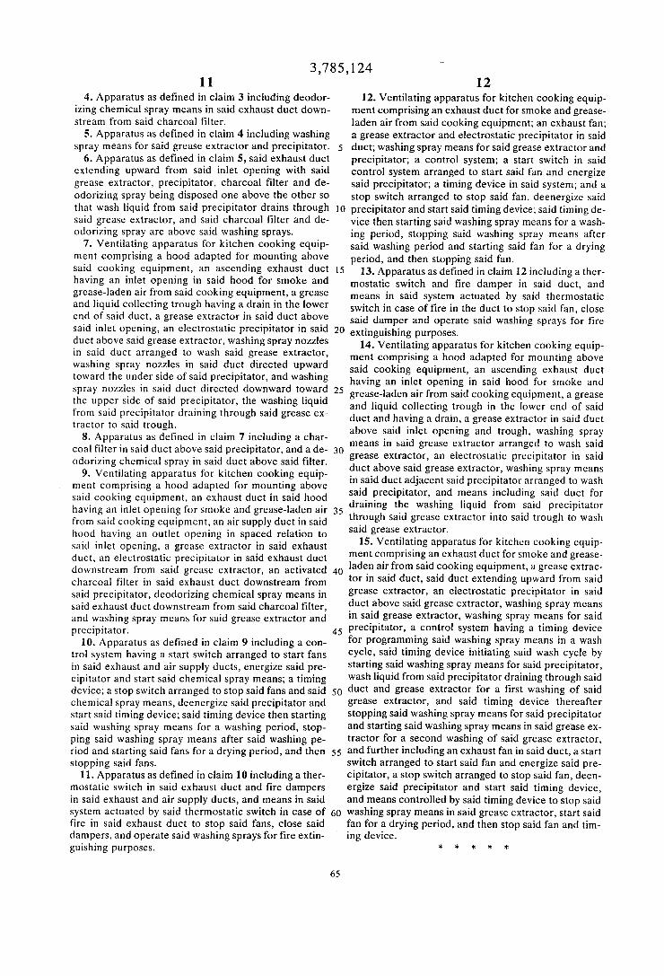
4. Apparatus as defined in claim 3 including deodorizing chemical spray means in said exhaust duct downstream from said charcoal filter.
5. Apparatus as defined in claim 4 including washing spray means for said grease extractor and precipitator. 5
6. Apparatus as defined in claim 5, said exhaust duct extending upward from said inlet opening with said grease extractor, precipitator, charcoal filter and deodorizing spray being disposed one above the other so that wash liquid from said precipitator drains through JO said grease extractor, and said charcoal filter and deodorizing spray are above said washing sprays.
7. Ventilating apparatus for kitchen cooking equipment comprising a hood adapted for mounting above said cooking equipment, an ascending exhaust duct J 5 having an inlet opening in said hood for smoke and grease-laden air from said cooking equipment, a grease and liquid collecting trough having a drain in the lower end of said duct, a grease extractor in said duct above said inlet opening, an electrostatic precipitator in said 20 duct above said grease extractor, washing spray nozzles in said duct arranged to wash said grease extractor, washing spray nozzles in said duct directed upward toward the under side of said precipitator, and washing spray nozzles in said duct directed downward toward 25 the upper side of said precipitator, the washing liquid from said precipitator draining through said grease extractor to said trough.
8. Apparatus as defined in claim 7 including a charcoal filter in said duct above said precipitator, and a de- 30 odorizing chemical spray in said duct above said filter.
9. Ventilating apparatus for kitchen cooking equipment comprising a hood adapted for mounting above said cooking equipment, an exhaust duct in said hood having an inlet opening for smoke and grease-laden air 35 from said cooking equipment, an air supply duct in said hood having an outlet opening in spaced relation to said inlet opening, a grease extractor in said exhaust duct, an electrostatic precipitator in said exhaust duct downstream from said grease extractor, an activated 40 charcoal filter in said exhaust duct downstream from
12 12. Ventilating apparatus for kitchen cooking equip
ment comprising an exhaust duct for smoke and greaseladen air from said cooking equipment; an exhaust fan; a grease extractor and electrostatic precipitator in said duct; washing spray means for said grease extractor and precipitator; a control system; a start switch in said control system arranged to start said fan and energize said precipitator; a timing device in said system; and a stop switch arranged to stop said fan, deenergize said precipitator and start said timing device; said timing device then starting said washing spray means for a wash-ing period, stopping said washing spray means after said washing period and starting said fan for a drying period, and then stopping said fan.
13. Apparatus as defined in claim 12 including a thermostatic switch and fire damper in said duct, and means in said system actuated by said thermostatic switch in case of fire in the duct to stop said fan, close said damper and operate said washing sprays for fire extinguishing purposes.
14. Ventilating apparatus for kitchen cooking equipment comprising a hood adapted for mounting above said cooking equipment, an ascending exhaust duct having an inlet opening in said hood for smoke and grease-laden air from said cooking equipment, a grease and liquid collecting trough in the lower end of said duct and having a drain, a grease extractor in said duct above said inlet opening and trough, washing spray means in said grease extractor arranged to wash said grease extractor, an electrostatic precipitator in said duct above said grease extractor, washing spray means in said duct adjacent said precipitator arranged to wash said precipitator, and means including said duct for draining the washing liquid from said precipitator through said grease extractor into said trough to wash said grease extractor.
15. Ventilating apparatus for kitchen cooking equipment comprising an exhaust duct for smoke and greaseladen air from said cooking equipment, a grease extractor in said duct, said duct extending upward from said grease extractor, an electrostatic precipitator in said duct above said grease extractor, washing spray means in said grease extractor, washing spray means for said
said precipitator, deodorizing chemical spray means in said exhaust duct downstream from said charcoal filter, and washing spray means for said grease extractor and precipitator.
10. Apparatus as defined in claim 9 including a control system having a start switch arranged to start fans
45 precipitator, a control system having a timing device for programming said washing spray means in a wash cycle, said timing device initiating said wash cycle by starting said washing spray means for said precipitator, in said exhaust and air supply ducts, energize said pre
cipitator and start said chemical spray means; a timing device; a stop switch arranged to stop said fans and said 50 chemical spray means, deenergize said precipitator and start said timing device; said timing device then starting said washing spray means for a washing period, stopping said washing spray means after said washing period and starting said fans for a drying period, and then 55 stopping said fans.
11. Apparatus as defined in claim 10 including a thermostatic switch in said exhaust duct and fire dampers in said exhaust and air supply ducts, and means in said system actuated by said thermostatic switch in case of 60 fire in said exhaust duct to stop said fans, close said dampers, and operate said washing sprays for fire extinguishing purposes.
65
wash liquid from said precipitator draining through said duct and grease extractor for a first washing of said grease extractor, and said timing device thereafter stopping said washing spray means for said precipitator and starting said washing spray means in said gre·ase extractor for a second washing of said grease extractor, and further including an exhaust fan in said duct, a start switch arranged to start said fan and energize said pre-cipitator, a stop switch arranged to stop said fan, deenergize said precipitator and start said timing device, and means controlled by said timing device to stop said washing spray means in said grease extractor, start said fan for a drying period, and then stop said fan and tim-ing device.
* * * * *