
GAYLORD INDUSTRIES - download.gaylordusa.comdownload.gaylordusa.com/Tech Manuals/Dry Ventilators...
24
THE GAYLORD VENTILATOR TECHNICAL MANUAL FOR THE GRAND “GX2” SERIES NON WATER-WASH VENTILATORS 10900 S.W. AVERY STREET • TUALATIN, OREGON 97062-1149 U.S.A. 800-547-9696 • 503-691-2010 • FAX: 503-692-6048 • email: [email protected] GAYLORD INDUSTRIES EFFECTIVE DATE 4-05
Transcript of GAYLORD INDUSTRIES - download.gaylordusa.comdownload.gaylordusa.com/Tech Manuals/Dry Ventilators...

THEGAYLORD VENTILATOR
TECHNICAL MANUAL
FOR THE GRAND “GX2” SERIESNON WATER-WASH VENTILATORS
10900 S.W. AVERY STREET • TUALATIN, OREGON 97062-1149 U.S.A.800-547-9696 • 503-691-2010 • FAX: 503-692-6048 • email: [email protected]
GAYLORD INDUSTRIES
EFFECTIVE DATE 4-05

To Our Customers. . .
Congratulations on your recent purchase of a Gaylordkitchen exhaust hood system. We are proud to be ableto provide you with a quality product that incorporatesthe latest engineering concepts and is a result of over50 years of experience in the foodservice kitchenexhaust industry.
If you have other Gaylord equipment such as a GaylordUtility Distribution System, Quencher Fire Protection Sys-tem, or Roof Top Air Handling Equipment, etc., pleaserefer to the corresponding supplementary equipmentmanuals.
If you have further questions, please call us toll free at1-800-547-9696 or email:[email protected]. We aremore than happy to help.
Sincerely,
Gaylord Industries
STREET ADDRESS: 10900 S.W. Avery Street, Tualatin, Oregon 97062-8549 U.S.A.PHONE: 503-691-2010 • 800-547-9696 • FAX: 503-692-6048 • email: [email protected] • www.gaylordusa.com
GAYLORD INDUSTRIES, INC.World Headquarters: 10900 S.W. Averry Street • Tualatin, Oregon 97062-1149 U.S.A.
“Undisputed World Leader inEngineered Systems forCommercial Kitchens”tm
COMMERCIAL KITCHEN EXHAUST SYSTEMS • FIRE PROTECTION • UTILITY DISTRIBUTION • ROOF TOP UNITS • POLLUTION CONTROL
TABLE OF CONTENTS
“GX2” SERIES PRINCIPLE OF OPERATION........................................................ 3
STANDARD MODELS............................................................................................ 6
MAINTENANCE AND CLEANING INSTRUCTIONS.............................................. 7
TROUBLESHOOTING ........................................................................................... 8
MEASURING INLET SLOT VELOCITY ................................................................. 10
WIRING DIAGRAMS .............................................................................................. 13
PARTS LIST ........................................................................................................... 17
START-UP INSPECTION REPORT ....................................................................... 20
WARRANTY ................................................................................. Inside back cover
© Copyright 2005, Gaylord Industries
ADDITIONAL COPIES $10.00
The manufacturer reserves the right to modify the materials andspecifications resulting from a continuing program of product im-provement or the availability of new materials.
ALL RIGHTS RESERVED. NO PART OF THIS BOOK MAY BE REPRODUCED, STOREDIN A RETRIEVAL SYSTEM, OR TRANSMITTED IN ANY FORM BY AN ELECTRIC, ME-CHANICAL, PHOTOCOPYING, RECORDING MEANS OR OTHERWISE WITHOUT PRIORWRITTEN PERMISSION OF GAYLORD INDUSTRIES, INC. COPYRIGHT 2003.
PATENT NUMBERSU.S.A.: 4,266,529
4,281,6354,356,870
CANADA: 1,139,1511,155,366
GERMANY: 8,034,240

The Gaylord “GX2” Series Non Water-Wash Ventilatoroffers simplicity, economy and performance that no otherventilator can offer. The unique “extractor insert” gives agrease extraction efficiency far superior to that of a typicalbaffle filter. The Gaylord “GX2” Series Ventilators are ULListed and meet all the requirements of NFPA #96 and theInternational Mechanical Code.
EXHAUST FAN OPERATIONThe exhaust fan is controlled by the Gaylord C-150“Exhaust Fan Start/Stop Switch”, an optional switch, or astandard wall switch. The switch is usually located on awall near the ventilator. When the switch is flipped up to theon position, the damper begins opening to the exhaustposition (refer to Fig. 1). After the damper opens (approxi-mately 80 seconds) the exhaust fan will come on.
GREASE EXTRACTIONThe Gaylord “GX2” Series Ventilator extracts 90% of thegrease, dust, and lint particles from the airstream passing
“GX2” SERIES PRINCIPLE OF OPERATION
through it. Grease extraction is accomplished by unique,removable stainless steel “extractor inserts” which incor-porates a series of horizontal baffles. As the air movesthrough the extractor at high speed, it is forced to make aseries of turns around these baffles, forcing the heavier-than-air particles of grease, dust, and lint to be thrown outof the airstream by centrifugal force. The sticky greasecollects in the extractor and the liquified grease drainsdown into the main grease gutter which slopes to thegrease cup. Note: Some ventilators may be equipped withoptional “Custom Air” baffles (shown dotted) to reduce theexhaust volume over specific light duty cooking appli-ances. The extractor inserts come in two sizes15½" (5.6lbs.) and 19½" (6.75 lbs.). IMPORTANT NOTE: Neveroperate ventilator without extractor inserts in place.
FIG. 1
3

“GX2” SERIES PRINCIPLE OF OPERATION
FIG. 2
CLEANINGAt the end of the cooking day the exhaust fan is turned offby the “Exhaust Fan Start/ Stop Switch.” In addition to thefan going off, the two position damper moves to the fan offposition (See Fig 2.). This prevents conditioned air fromgoing up the exhaust system during off hours. After the fanhas been turned off, the extractor inserts are removed and
can be washed either in a dishwasher or soaked andrinsed off. The grease cup is also removed and emptied atthis time. To ease in the removal of the extractor inserts,an “Extractor Removal Tool” is available which eliminatesthe need for kitchen personnel to climb up on the cookingequipment, or up a ladder.
4

“GX2” SERIES PRINCIPLE OF OPERATION
FIRE PROTECTION
NFPA #96 requires the use of surface, duct and plenumprotection on all hoods. It is these systems that are the firstline of defense against equipment fires.
The “GX2” Series ventilator incorporates a two positiondamper, a fail safe damper control and a fail safe thermostat.In the event of a fire, should the thermostat located at the ductcollar reach 250°F, the damper control is de-energizedclosing the damper to the fire position (See Fig. 3) and theexhaust fan shuts off. This prevents the flames from entering
the ductwork and spreading to other parts of the building. Thefire is contained in the kitchen area where it can be properlyfought. After the thermostat cools below 250°F, the damperautomatically opens to the exhaust position and the fanre-starts.
Surface, duct collar and plenum fire protection utilizing TheGaylord Quencher System or other fire protection systemscurrently on the market can be factory installed as an option.
FIG. 3
5

STANDARD VENTILATOR MODELS
STANDARD MAKE-UP AIR OPTIONSThe make-up air options shown below are available on all BDL Series Ventilators
except the MAI Series is not available on the GX2-BDL-CL.
This method of introducing air into the hood istypically referred to as the “short circuit” method.This design has very limited applications and theamount of supply air able to be introduced variesconsiderably with the type of cooking equipment.This air may be untempered air in most areasdepending upon climatic conditions and the typeof cooking equipment. The difference betweenthe quantity of air being introduced and theamount of air being exhausted must be suppliedthrough a traditional make-up air system.
This method of introducing make-up air into thekitchen is flexible and has many advantages.Make-up air is discharged through stainless steelperforated panels as illustrated (MAW Series) oroptional registers (MAR Series). Typical supplyvolume is 80% of the exhaust or more, depend-ing on air balance desired. Supply air tempera-tures should range from 60 to 65°F (16 to 18°C),but may be as low as 50°F (10°C) depending onair volume, distribution, and internal heat load.
MODEL “MAW” SERIESFRONT FACE DISCHARGE
MODEL “MAI” SERIESINTERNAL DISCHARGE
Model GX2-BDL
Application - Wall mounted canopystyle for all types of equipment.
Model GX2-BDL-BB
Application - For island stylecooking arrangements over all duties
of equipment.
Model GX2-BDL-DS
Application - For island stylecooking arrangements where one side
of the cooking line is light duty equipmentand the other side medium duty equipment.
Model GX2-BDL-CL
Application - For single islandarrangements
6

CLEANINGAt the end of each cooking day, the exposed interiorsurfaces of the ventilator should be wiped down and thegrease cup emptied. During the course of operation, greaseparticles are gradually collecting inside the extractor inserts.Daily, or at periodic intervals, depending on the type of cook-ing, the extractor inserts must be removed and cleaned.To clean, proceed as follows:
1.Remove extractor inserts by hand or by using theextractor removal tool. CAUTION: Care should betaken when removing extractors, especially over fry-ers. It is recommended that the cooking equipment becooled down and the fryers be covered prior to removingextractors. To remove, lift up slightly on extractor insertand pull straight out.
2.Extractor inserts may be cleaned either by using a dish-washer or by washing in a sink using hot water and adegreasing detergent. Formula G-510 is highlyrecommended for this application. For informationcontact:20/10 Products Inc.P.O. Box 7609Salem, OR 97303Phone: 800-286-2010Fax: 503-363-4296E-mail: [email protected]
3.With the extractor inserts removed, wipe and clean theback wall and the grease gutter with hot detergent wa-ter. NOTE: If a steam or hot water pressure washer isused for periodic cleaning of the interior, connect a hoseto the gutter drain and lead it to a floor sink or largebucket to drain off the water.
4.To replace the extractor inserts, care must be taken toinsure that point “A” rests in the rear clip as illustratedin Fig. 4.
5.If the ventilator(s) has a fuse link operated supply ductfire damper NFPA-96 requires inspection of the fuselink every 6 months and replacement annually.
ELUDEHCSNOITCEPSNIMETSYSTSUAHXE
snoitarepognikoocleufdilosgnivressmetsyS ylhtnoM
sahcussnoitarepognikoocemulov-hgihgnivressmetsySgnikoockowrogniliorbrahc,gnikoocruoh-42
ylretrauQ
snoitarepognikoocemulov-etaredomgnivressmetsyS yllaunnaimeS
sahcus,snoitarepognikoocemulov-wolgnivressmetsySroinesro,sessenisublanosaes,spmacyad,sehcruhc
sretnecyllaunnA
INSPECTION AND CLEANING REQUIREMENTSThe 2001 edition of NFPA-96 (Standard for Ventilation Con-trol and Fire Protection of Commercial Cooking Operations)require that hoods, ducts and exhaust fans be inspectedby a properly trained, qualified and certified company orperson(s) in accordance with the following table.Upon inspection, if found to be contaminated with depositsfrom grease- laden vapors, the entire exhaust system shallbe cleaned by a properly trained, qualified, and certifiedcompany or person(s) acceptable to the authority havingjurisdiction.When a vent cleaning service is used, a certificate show-ing date of inspection or cleaning shall be maintained onthe premises. After cleaning is completed, the ventcleaning contractor shall place or display within the kitchenarea a label indicating the date cleaned and the name ofthe servicing company. It shall also indicate areas notcleaned. Factory trained service agencies are certified byGaylord Industries, Inc. to perform these inspections. Forthe name and phone number of your nearest agent call800-547-9696 or www.gaylordusa.com and go to service.
MAINTENANCE AND CLEANING INSTRUCTIONS
7
CAUTION: Care should be taken when removing extractors,especially over fryers. It is recommended that the cookingequipment be cooled down and the fryers be covered prior toremoving extractors.
FIG. 4

TROUBLE-SHOOTING
8
MOTPMYS MELBORPELBISSOP NOITCAEVITCERROCSSOLEKOMS
.1 tonsirotalitneV-ssoLekomS.ylreporpgnitsuahxe
.A
.B
.C
.D
.E
yticolevriaegarevA-yticolevriawoLniebdluohstolsyrtneriaehthguorhtnotrahCyticoleVriAehthtiwecnadroccagnirusaemfodohtemreporproF.01egapehtfI.11egapotrefer,yticolevriaeht
.gniwollofehtkcehcwolsiyticolev
nwostievahtsumrotalitneVdrolyaGehT,tsuahxerehtoondnametsystsuahxedeitebdluohs,sdoohrehsawhsidsahcus
.tiotni
.sresuffidriapu-ekamdecalpylreporpmI
.riapu-ekametauqedanI
.egrahcsidnaftsuahxE
.1
.2
.3
.4
.5
.1
.1
.2
.3
.1
.2
.1
.2
.naftsuahxeehtnotlebgnippilsronekorB
.leehwnaftsuahxeehtfonoitatorreporP
tsumnaf(naftsuahxefoezisreporP.)gnitaretalpemanreviled
.nepotfellenapnoitcepsnikrowtcuD
.noitisopreporpnironepotonrepmaD
erehttahtyfirevdnametsystcudtcepsnIepytonera II fI.nideitsmetsysrotalitnev
.devomerebtsumyehtos
lliwrotalitnevehttadetceridriapu-ekaMriaehtgnitpursidstfardssorcetaercylekilsrevuolehttsujdA.rotalitnevehtotniwolfehtmorfyawariapu-ekamehttceridot
.rotalitnev
hguorhtdereviledebdluohsriapu-ekaMsretsigerrosresuffiddetarofrephtgnelllufehttuohguorhtdetubirtsidthgiehgniliecta
.aeranehctik
ehtraendetacolsretsigerriapu-ekaMdetsujdaebdluohssrevuoleht,rotalitnev.rotalitnevehtmorfyawariaehttceridot
ehttariapu-ekamgnicrofrognitceriDstfardssorcsetaercyllacipytrotalitnev
.ssolekomsnignitluser
rofdeilppusebtsumriapu-ekaMllahguorhtdetsuahxeriafotnemecalper
.smetsystsuahxenehctik
ot%57tahtsi"bmuhtfoelur"larenegAebdluohsriatnemecalperehtfo%08ria)deloocrodetaeh(,denoitidnoc,hserfehthtiw,aeranehctikehtotnithguorbotniwolfotdewolla%52ot%02gniniamer
.saeratnecajdamorfnehctikeht
ehtrevoneercsonebdluohserehTebdluohsti,dnuofsienofI.egrahcsid
.devomer
ebtondluohsegrahcsidfonoitceridehTdrawnwodronsdniwgniliaverpehtotniylhgihsiegrahcsidlacitrevA.foorehtotno
.dednemmocer
NOITCARTXEESAERG
.1 .noitcartxEesaerGrooP .A rotalitneVseireS"2XG"drolyaGehTdnatsud,esaergehtfo%09otpustcartxegnissapmaertsriaehtmorfselcitraptnildeniatniamdnadetareponehw,tihguorht.snoitacificepsngisedhtiwecnadroccanitonsirotalitnevehttahtsraeppatifItsuahxeehtyllacipyt,ylreporpgnitcartxe
.wolsiemulov
.1 debircsedsayticolevtolstelniehtkcehCsiyticolevehtfI.21hguorht01segapnoroesaercni,egnarderiuqerehtnihtiwton
.deriuqersadeepsnafehtecuder

9
TROUBLE-SHOOTING
MOTPMYS MELBORPELBISSOP NOITCAEVITCERROCNAFTSUAHXE
.1
.2
repmadtubnodenrutsihctiwsnafehTdnanoitisopnepoehtotevomtonseodnacuoytubtratstonseodnaftsuahxe
.gninnurnafehtraeh
ehtnodenrutsihctiwsnafehtnehwfInoitsoptsuahxeehtotsevomrepmad.noemoctonseodnaftsuahxeehttub
.A
.A
.B
.C
.D
.E
deriwneebtonsahhctiwsffo/nonaF.rotalitnevehthguorht
retratscitengamnorotcetorpdaolrevO.deppirt
epyt)citamotuA/nOsdnaH(AOHnafIeht,desusihctiwsretratscitengamdevomneebevahyamhctiwsrotceles
noitisopcitamotuaehtmorf
.deppirtrekaerbtiucricnaftsuahxE
nahtiwdeppiuqesimetsysehtfIa,naftsuahxeehtrofhctiwstcennocsid
.tuonwolbevahyamsesufroesuf
deriwneebtonsahhctiwsffo/nonaF.rotalitnevehthguorhtylreporp
.1
.1
.1
.1
.1
.1
sihtnimargaidgniriwotrefeR.eriw-erdnalaunam
ehtnonottub"teseR"ehthsuPehthsupehtdnaretratscitengamdnammocehtnonottub"naFtratS"
.retnec
ehtotrotcelesnrutdnahctiwskcehC.noitisopcitamotua
rekaerbtiucrictes-eR
dnasesuffoytiunitnockcehC.yrassecenfiecalper
sihtnimargaidgniriwotrefeR.eriw-erdnalaunam

MEASURING INLET SLOT VELOCITYSmoke capture and grease extraction efficiency are de-pendent upon the proper air velocity at the inlet slot of theventilator.The required average slot velocities are shownon the “Air Velocity Chart” below. If the slot velocity isbelow the required average, the exhaust fan must be ad-justed accordingly.NOTE: The height of the inlet slot can vary dependingupon the design of the ventilator. It is, therefore, impor-tant to first measure the inlet slot and compare it to thechart below to determine the required average inlet slotvelocity. The designed CFM per lineal foot is related tothe velocity as shown on the chart below. The total CFMfor the ventilator can be found on the ventilator name-plate. (See Figure 6).
Air velocity readings less than what is specified on the“Air Velocity Chart” may allow smoke and grease to es-cape the confines of the ventilator and/or reduce greaseextraction efficiency. This can result in grease depositswhich lead to sanitation problems or fire hazards if leftuncorrected. If air velocity readings are higher than thosespecified, it will require more energy to operate the ex-haust fan and excessive noise levels will result. Higheror lower velocities than the required average will normallyput the entire heating and ventilating system out of bal-ance. When measuring the air velocity it is very importantto take an average reading across the inlet slot plane asdescribed on Page 11. Positioning the sensing head in-correctly will give velocity readings that cannot be com-pared to the “Air Velocity Chart”.
MEASURING INLET SLOT VELOCITY
10
TRAHCYTICOLEVRIA
SEIRES"SD"TPECXESEIRES"2XG"LLAROF
lanimoNthgieH
fotolStelnI
motsuCtuohtiWselffaBriA
motsuChtiWselffaBriA
dengiseDrepMFC.tFlaeniL
telnIegarevA)MPF(yticoleVtolS
.niM mumitpO .xaM
dengiseDrepMFC.tFlaeniL
telnIegarevA)MPF(yticoleVtolS
.niM mumitpO .xaM
"3
"4
052
072
582
003
004
0031
0631
5241
5641
0961
0831
5341
0051
5451
0871
0541
0051
5751
5261
0781
051
061
071
081
052
067
097
018
548
0401
008
038
558
088
5901
088
078
009
539
0511
*SROTALITNEVSEIRES"SD"ROF
rePMFCdengiseD.tFlaeniL
telnIegarevAderiuqeR)MPF(yticoleVtolS
latoThtoBstolS
tnorFtolS
raeRtolS
tolStnorF
.niM mumitpO .xaM
tolSraeR
.niM mumitpO .xaM
003
004
051
052
051
051
067
5731
008
0541
088
0251
595
595
526
526
556
556

11
MEASURING INLET SLOT VELOCITY
FIG. 5A
FIG. 5B
FIG. 5C
CROSS SECTION OF TYPICALVENTILATOR INLET SLOTS
The standard instrument used for measuring the inlet velocities on aGaylord Ventilator is a Pacer, Model DA40 or DA4000 Digital Anemometer.This instrument is the easiest, most accurate and the best suited formeasuring ventilator inlet slot velocities. To take accurate air velocityreadings, follow the instructions below.
Instructions1. It is first necessary to determine if the ventilator includes Custom Airbaffles as shown in Fig. 5B. If shop drawings are available, and if equipped,the custom baffles and their location will be noted on the front elevation. Ifnot available, to determine if Custom Air baffles are provided run your handalong the bottom inlet slot and feel for the Custom Air baffle as illustratedin Fig. 5B.
2. If the ventilator includes Custom Air baffles, it will be necessary to taketwo sets of readings - one for the section of ventilator that includes CustomAir baffles and one where it does not.
3. Attached the sensing head guide bracket, Gaylord Part Number 18408,to the sensing head.
4. Attach the cable from the sensing head to the meter and the handlesections to the sensing head.
5. Place the sensing head guide bracket against the lower lip of the inlet slotas illustrated.
6. Using the 16 second averaging feature on the meter, slide the sensinghead along the slot, back and forth, for a 3'-0" to 4'-0" distance, and recordthe velocity at the end of the 16 second mark. Continue this process for thefull length of the ventilator.
Important Note: If the ventilator includes custom air baffles as illustratedin Fig. 5B, always take separate readings on the section of the ventilator thatincludes custom air from the section that does not have the baffles. Noncustom air and custom air readings must be recorded separately. Do notaverage them together.
Important Note: On the rear slot of a Model BDL-DS Series, do not use theguide bracket. Refer to Figure 5C.
7. Record the velocity (fpm) on the start up inspection report form. A samplereport form, which can be photocopied, is provided on page 16.
8. The designed, or optimum velocity, is noted on the shop drawings andthe Air Velocity Chart on page 10. Two velocities will be noted if theventilator includes custom air baffles.
9. Compare the recorded air velocity to the designed air velocity shown onthe shop drawings or the Air Velocity Chart on page 10. The recordedvelocity may be slightly lower or higher providing that it is within the minimumand maximum range as shown on the Air Velocity Chart .
If the air velocity is outside the minimum/maximum range, the performanceof the ventilator will be affected and therefore the exhaust fan must beadjusted.

The total required exhaust volume can befound stamped on the UL nameplate locatedon each hood section.
FIGURE 6
MEASURING INLET SLOT VELOCITY
12
1. MINIMUM TOTAL EXHAUSTVOLUME FOR THIS HOOD SECTION
2. MAXIMUM TOTAL SUPPLYVOLUME FOR THIS HOOD SECTION
3. EXHAUST STATIC PRESSURE ATDUCT COLLAR
4. SUPPLY STATIC PRESSURE ATDUCT COLLAR
5. THIS HOOD SECTION SUITABLE FOR APPLIANCES WITH MAXIMUM COOKINGSURFACE TEMPERATURE OF:
°F FOR LINEAL FT. OF HOOD
°F FOR LINEAL FT. OF HOOD
6. REFER TO GAYLORD VENTILATOR TECHNICAL MANUAL FOR INLETVELOCITY REQUIREMENTS AND METHOD OF CHECKING VELOCITY
7. ELECTRICAL RATING OF LIGHT FIXTURES: 120 VOLT, 60 HZ. OR 220 VOLT,50 HZ. OVERALL RATING - 12 AMPS OR LESS
8. ON "GX2" and "PG" SERIES VENTILATORS EQUIPPED WITH FUSE LINKOPERATED EXHAUST FIRE DAMPER USE ONLY 280° F , RATED 30 LBS. MIN. ULLISTED FUSIBLE LINK FOR REPLACEMENT
9. IF HOOD IS EQUIPPED WITH INTEGRAL MAKE-UP AIR WITH FUSE LINK OPER-ATED FIRE DAMPER USE ONLY 165° F, RATED 30 LBS. MIN. UL LISTED FUSIBLELINKS FOR REPLACEMENT
10.DUCTWORK AND EXHAUST FANA. STATIC PRESSURE OF DUCT SYSTEM MUST BE ADDED TO VENTILATOR
STATIC FOR TOTAL SYSTEM STATICB. ALL DUCTWORK MUST BE WELDED LIQUIDTIGHT
HOOD MOUNTING REQUIREMENTSMINIMUM DISTANCE FROM COOKING SURFACE TO FRONTLOWER EDGE OF HOOD
MAXIMUM DISTANCE FROM COOKING SURFACE TO FRONTLOWER EDGE OF HOOD
MINIMUM OVERHANG FROM FRONT OF HOOD CAVITY TOFRONT OF COOKING SURFACE
MAXIMUM SETBACK FROM FRONT OF HOOD CAVITY TOFRONT OF COOKING SURFACE
MINIMUM OVERHANG FROM SIDE OF HOOD TO EDGE OFCOOKING SURFACE
SERIAL NO:MODEL NO:
W.G.
W.G.
ENGINEERING DATA
THIS EXHAUST HOOD HAS BEEN TESTEDTO STANDARD UL 710 "EXHAUST HOODSFOR COMMERCIAL COOKINGEQUIPMENT"
THIS EXHAUST HOOD IS LISTED UNDER ULFILE NUMBER MH11403
THIS EXHAUST HOOD MEETS ALL REQUIRE-MENTS OF THE LATEST EDITION OF NFPA-96 AND THE IMC (INTERNATIONAL MECHANI-CAL CODE)
o SUPPLIED WITH FACTORY INSTALLED UL LISTED
GRINNELL CORP. EA-1, 1/4" ORIFICE, 65 DEGREEDEFLECTOR SPRINKLER(S) FOR THE PROTEC-TION OF UNLIMITED LENGTH OF GREASE DUCTHAVING A MAXIMUM DUCT PERIMETER OF 50INCHES PER SPRINKLER. CONNECT TO NFPA 13SPRINKLER SYSTEM WATER SUPPLY ONLY.
PATENT PENDING
EXHAUST HOOD WITHEXHAUST DAMPER
UL-GX2/PG 1000
WORLD HEADQUARTERS
GAYLORD INDUSTRIES, INC.10900 S.W. AVERY STREET
TUALATIN, OR 97062-8549 USA
PHONE: 1-503-691-2010FAX: 1-503-692-6048
EMAIL: [email protected]
LISTED370Y
C.F.M.
C.F.M.
MAINTENANCE INSTRUCTIONS1. REMOVE, INSPECT AND CLEAN FILTERS OR GAYLORD EXTRACTOR
CARTRIDGES AS REQUIRED2. REMOVE AND EMPTY GREASE CUP AS REQUIRED3. CAUTION - DO NOT OPERATE VENTILATOR WITHOUT FILTERS OR EXTRACTOR
CARTRIDGES IN PLACE4. REPLACE FILTERS IN "PG" SERIES ONLY WITH UL CLASSIFIED GREASE FILTERS.
IN "PGX" AND "GX2" SERIES REPLACE WITH GAYLORD INDUSTRIESEXTRACTOR CARTRIDGES.
5. IF THE VENTILATOR(S) HAS A FUSE LINK OPERATED EXHAUST OR SUPPLYDUCT FIRE DAMPER THE NATIONAL FIRE PROTECTION ASSOCIATION'SPAMPHLET NFPA-96 REQUIRES INSPECTION OF THE FUSE LINK EVERY 6MONTHS AND REPLACED ANNUALLY. REFER TO THE GAYLORD VENTILATORTECHNICAL MANUAL FOR DETAILS.
TOTAL EXHAUST CFM HERE
TOTAL SUPPLY CFM HERE
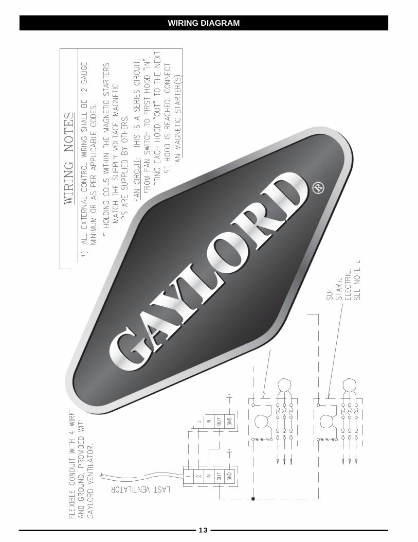
13
WIRING DIAGRAM
WIRING DIAGRAM
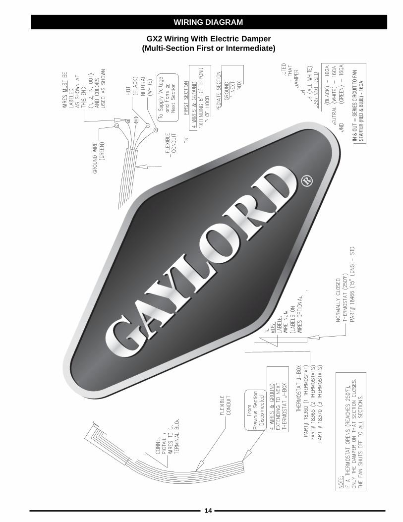
14
GX2 Wiring With Electric Damper(Multi-Section First or Intermediate)

WIRING DIAGRAM
15
GX2 Wiring With Electric Damper(Single Section or Last Section)

WIRING DIAGRAM
16

DROLYAG.ONTRAP
NOITPIRCSED NOITARTSULLI
0838158381
tresnIrotcartxE"2/1-51tresnIrotcartxE"2/1-91
)srotcartxE.tF.niL/MFC052(
5478164781
tresnIrotcartxE"2/1-51tresnIrotcartxE"2/1-91
)srotcartxE.tF.niL/MFC004(
12301 stcuDylppuSrofkniLesuFF°561
6088166481
).C.N(tatsomrehTtcuDtsuahxE)rotcartxE052roF(.F°052htgneL"6)rortcartxE004roF(.F°052htgneL"51
00481looTlavomeRrotcartxE
)srotcartxE.tF.niL/MFC004+052roF(
91101 raelC-ebolGthgiL
11231emarF&sneLthgiLtnecsednacnI
reniateR&sneLthgiLdesseceR"21x"21
012311110121101
emarF&sneLthgiLtnecseroulFreniateR&sneLthgiLdesseceR.tF2reniateR&sneLthgiLdesseceR.tF3reniateR&sneLthgiLdesseceR.tF4
57031 "4x"6x"4/1-3puCesaerG
41381 lortnoChctiwSpotS/tratS051-C
PARTS LIST
17

DAMPER CONTROL
MODEL C-99 SERIES
18
1. Damper Control With Linkage (120 Volt) ---------------------------------- 18451
.CP
.ONNOITPIRCSED
DROLYAG.ONTRAP


VENTILATOR START-UP INSPECTION REPORT
MAKE-UP AIR1. Kitchen make-up air supply is turned on______Yes______No2. Type of make-up air¨ Ceiling Registers ¨ Built into Hood¨ Ceiling Linear Diffusers ¨ Other
3. If ceiling register or linear diffusers approximate distance from face of hood
_____________________________________________________________
FIRE DAMPER INFORMATION¨ Ventilator has electric fire damper (GX2 Series)¨ Ventilator has fuse link fire damper (GX2-FLD Series)
¨ Ventilator does not have a fire damper (GX2-ND Series)
AIR VOLUME READINGSPush “Start Fan” and take velocities. Record as follows: Exhaust record in the “EX” row, Exhaust at CustomAir baffles (if applicable) record in the “CA” row, and Make-up Air record in the “MA” row.
ELECTRIC DAMPER TEST (If equipped) :1. Remove one or more extractors so damper is visible. Push the “START FAN” button.
A. The damper should move to the fully opened position in approx. 1 minute 15 seconds. _____Yes ___NoB. The exhaust fan came on ___Yes ___No
2. Push “STOP FAN” button.A. The damper should move to the fully closed position in approx. 15 seconds_____Yes_____NoB. The exhaust fan shut off ___Yes ___No
For Model “GX2” Series VentilatorsJob Name ______________________________________________________________________________ Gaylord Representative ____________________________________________________________
Address ________________________________________________________________________________ Representative Company Name ______________________________________________________
______________________________________________________________________________________ File Number _______________________________________________ Date _________________
City/State Zip
Facility Contact Name _________________________________________ Phone # ____________________ CSA Contacted __________________________________________________________________
3. If the “GX2” Series ventilator(s) is interconnected with any “CG3” water wash series, perform the followingtest:A. With the exhaust fan on, open the electrical compartment on the control cabinet and push the “FIRETEST” button. The following should occur:
1. Exhaust fan shut off ___Yes ___No2. Damper fully closed ___Yes ___No
B. At conclusion of the test push the “CANCEL” button. The following should occur:1. The damper stayed closed ___Yes ___No2. Fan stayed off ___Yes ___No
C. Push the “START FAN” button. The following should occur:1. Damper moves to the fully open position ___Yes ___No
2. Exhaust fan comes on ___Yes ___No
INSTALLATION INCLUDES THE FOLLOWING:
¨ Gaylord Rooftop Unit (GRT)
¨ Gaylord Clearair Pollution Control Unit (RSPC) ¨ The Gaylord “Quencher” Fire Protection System
¨ Gaylord Distributor (UDS) ¨ Wet Chemical Fire Protection System
Personnel provided with ventilator technical manual________Yes________No
Inspection Witnessed By (Print Name) ______________________________________________________
Signature ________________________________________________ Date _______________________
Comments ____________________________________________________________________________
____________________________________________________________________________________
____________________________________________________________________________________
____________________________________________________________________________________
____________________________________________________________________________________
__________________________________________________________________________________________________
__________________________________________________________________________________________________
Distribution: WHITE-Gaylord Industries, Inc. YELLOW-Customer PINK-Dealer GOLDENROD-Sales Rep Litho U.S.A.GAYLORD INDUSTRIES 10900 S.W. Avery Street • Tualatin, OR 97062-1149
PHONE:1-503-691-2010 • FAX: 1-503-692-6048 • email:[email protected]
Form No. GX2SUR200
.ONMETI .ONLAIRESDOOHTHGIROTTFELMORF)MPF(SEITICOLEVRIA
EGRAHCSIDRIAPU-EKAMROTOLSDOOHEGAREVA
XE
AC
AM
XE
AC
AM
XE
AC
AM


LIMITED WARRANTY
The Gaylord Ventilator and component parts furnished with The Gaylord Ventilator by theLicensed Gaylord Manufacturer are warrantied by the Licensed Gaylord Manufacturerproducing the ventilator to be free from defects of material and workmanship under normaluse when installed, operated and serviced in accordance with factory recommendations.
The Licensed Gaylord Manufacturer's obligation under this warranty and any warrantiesimplied by law shall be limited to repairing or replacing at its option any part of saidequipment when the Licensed Gaylord Manufacturer's examination shall disclose to itssatisfaction to be thus defective, for a period of one (1) year from the date of beneficial use,or eighteen months from date of shipment, whichever occurs first, provided proper andacceptable evidence of such is recorded at the factory. THE LICENSED GAYLORD MANU-FACTURER SHALL NOT BE RESPONSIBLE FOR INCIDENTAL OR CONSEQUENTIALDAMAGES RESULTING FROM A BREACH OF THIS WARRANTY.
In the United States the labor required to make repairs and replacements under this war-ranty shall be furnished by Gaylord Industries Inc. or the Licensed Gaylord Manufacturer orits authorized representative. Such labor shall only be provided Mondays through Fridaysbetween the hours of 8 a.m. and 4 p.m. Requests for repairs or replacement parts shouldbe made to GAYLORD INDUSTRIES INC., P.O. Box 1149, Tualatin, Oregon 97062-1149.
Outside the United States, all replacement parts furnished under this warranty shall beF.O.B. Gaylord Industries, Inc., Tualatin, Oregon U.S.A. The owner shall pay the neces-sary freight delivery charges, and the necessary labor for removal and installation of parts,and any tariffs, duties or taxes.
This warranty does not cover routine maintenance or malfunctions or improper operationcaused by fluctuating electrical power or power surges, and improper exhaust fan opera-tion.
This is the sole warranty with respect to the aforesaid items. NEITHER THE GAYLORDLICENSEE NOR ANY OTHER PARTY MAKES ANY OTHER WARRANTY OF ANY KINDWHATSOEVER, EXPRESSED OR IMPLIED, AND ALL IMPLIED WARRANTIES OFMERCHANTABILITY AND FITNESS FOR A PARTICULAR PURPOSE WHICH EXCEEDTHE AFORESAID OBLIGATIONS ARE HEREBY DISCLAIMED AND EXCLUDED FROMTHIS AGREEMENT.
THE GAYLORD NON WATER-WASH VENTILATORLIMITED WARRANTY
August 2000
WORLDWIDE SALES, MANUFACTURING AND SERVICEFOR THE NAME AND LOCATION OF THE NEAREST
CERTIFIED SERVICE AGENCY, VISIT OUR WEB SITE:
WWW.GAYLORDUSA.COMOR CONTACT US AT:
FORM NO. TM-GX2 203 / 30401 © COPYRIGHT 2005, GAYLORD INDUSTRIES LITHO IN U.S.A.
GAYLORD INDUSTRIES10900 S.W. AVERY STREET
TUALATIN, OREGON 97062-1149 U.S.APhone: 503-691-2010
1-800-547-9696Fax: 503-692-6048
email: [email protected]
LOCAL SERVICE AGENCY