Up.scaler Extron In1508 Manual
85
IN1508 Scaling Presentation Switcher 68-791-01 Rev. G 03 08
-
Upload
bruno-dechen -
Category
Documents
-
view
274 -
download
2
Transcript of Up.scaler Extron In1508 Manual

IN1508Scaling Presentation Switcher
68-791-01 Rev. G03 08

This symbol is intended to alert the user of important operating and maintenance (servicing) instructions in the literature provided with the equipment.
This symbol is intended to alert the user of the presence of uninsulated dangerous voltage within the product’s enclosure that may present a risk of electric shock.
CautionRead Instructions • Read and understand all safety and operating instructions before using the equipment.
Retain Instructions • The safety instructions should be kept for future reference.
Follow Warnings • Follow all warnings and instructions marked on the equipment or in the user information.
Avoid Attachments • Do not use tools or attachments that are not recommended by the equipment manufacturer because they may be hazardous.
WarningPower sources • This equipment should be operated only from the power source indicated on the product. This
equipment is intended to be used with a main power system with a grounded (neutral) conductor. The third (grounding) pin is a safety feature, do not attempt to bypass or disable it.
Power disconnection • To remove power from the equipment safely, remove all power cords from the rear of the equipment, or the desktop power module (if detachable), or from the power source receptacle (wall plug).
Power cord protection • Power cords should be routed so that they are not likely to be stepped on or pinched by items placed upon or against them.
Servicing • Refer all servicing to qualifi ed service personnel. There are no user-serviceable parts inside. To prevent the risk of shock, do not attempt to service this equipment yourself because opening or removing covers may expose you to dangerous voltage or other hazards.
Slots and openings • If the equipment has slots or holes in the enclosure, these are provided to prevent overheating of sensitive components inside. These openings must never be blocked by other objects.
Lithium battery • There is a danger of explosion if battery is incorrectly replaced. Replace it only with the same or equivalent type recommended by the manufacturer. Dispose of used batteries according to the manufacturer’s instructions.
Ce symbole sert à avertir l’utilisateur que la documentation fournie avec le matériel contient des instructions importantes concernant l’exploitation et la maintenance (réparation).
Ce symbole sert à avertir l’utilisateur de la présence dans le boîtier de l’appareil de tensions dangereuses non isolées posant des risques d’électrocution.
AttentionLire les instructions• Prendre connaissance de toutes les consignes de sécurité et d’exploitation avant
d’utiliser le matériel.
Conserver les instructions• Ranger les consignes de sécurité afi n de pouvoir les consulter à l’avenir.
Respecter les avertissements • Observer tous les avertissements et consignes marqués sur le matériel ou présentés dans la documentation utilisateur.
Eviter les pièces de fi xation • Ne pas utiliser de pièces de fi xation ni d’outils non recommandés par le fabricant du matériel car cela risquerait de poser certains dangers.
AvertissementAlimentations• Ne faire fonctionner ce matériel qu’avec la source d’alimentation indiquée sur l’appareil. Ce
matériel doit être utilisé avec une alimentation principale comportant un fi l de terre (neutre). Le troisième contact (de mise à la terre) constitue un dispositif de sécurité : n’essayez pas de la contourner ni de la désactiver.
Déconnexion de l’alimentation• Pour mettre le matériel hors tension sans danger, déconnectez tous les cordons d’alimentation de l’arrière de l’appareil ou du module d’alimentation de bureau (s’il est amovible) ou encore de la prise secteur.
Protection du cordon d’alimentation • Acheminer les cordons d’alimentation de manière à ce que personne ne risque de marcher dessus et à ce qu’ils ne soient pas écrasés ou pincés par des objets.
Réparation-maintenance • Faire exécuter toutes les interventions de réparation-maintenance par un technicien qualifi é. Aucun des éléments internes ne peut être réparé par l’utilisateur. Afi n d’éviter tout danger d’électrocution, l’utilisateur ne doit pas essayer de procéder lui-même à ces opérations car l’ouverture ou le retrait des couvercles risquent de l’exposer à de hautes tensions et autres dangers.
Fentes et orifi ces • Si le boîtier de l’appareil comporte des fentes ou des orifi ces, ceux-ci servent à empêcher les composants internes sensibles de surchauffer. Ces ouvertures ne doivent jamais être bloquées par des objets.
Lithium Batterie • Il a danger d’explosion s’ll y a remplacment incorrect de la batterie. Remplacer uniquement avec une batterie du meme type ou d’un ype equivalent recommande par le constructeur. Mettre au reut les batteries usagees conformement aux instructions du fabricant.
Safety Instructions • English
Consignes de Sécurité • Français
Sicherheitsanleitungen • DeutschDieses Symbol soll dem Benutzer in der im Lieferumfang enthaltenen Dokumentation besonders wichtige Hinweise zur Bedienung und Wartung (Instandhaltung) geben.
Dieses Symbol soll den Benutzer darauf aufmerksam machen, daß im Inneren des Gehäuses dieses Produktes gefährliche Spannungen, die nicht isoliert sind und die einen elektrischen Schock verursachen können, herrschen.
AchtungLesen der Anleitungen • Bevor Sie das Gerät zum ersten Mal verwenden, sollten Sie alle Sicherheits-und
Bedienungsanleitungen genau durchlesen und verstehen.
Aufbewahren der Anleitungen • Die Hinweise zur elektrischen Sicherheit des Produktes sollten Sie aufbewahren, damit Sie im Bedarfsfall darauf zurückgreifen können.
Befolgen der Warnhinweise • Befolgen Sie alle Warnhinweise und Anleitungen auf dem Gerät oder in der Benutzerdokumentation.
Keine Zusatzgeräte • Verwenden Sie keine Werkzeuge oder Zusatzgeräte, die nicht ausdrücklich vom Hersteller empfohlen wurden, da diese eine Gefahrenquelle darstellen können.
VorsichtStromquellen • Dieses Gerät sollte nur über die auf dem Produkt angegebene Stromquelle betrieben werden.
Dieses Gerät wurde für eine Verwendung mit einer Hauptstromleitung mit einem geerdeten (neutralen) Leiter konzipiert. Der dritte Kontakt ist für einen Erdanschluß, und stellt eine Sicherheitsfunktion dar. Diese sollte nicht umgangen oder außer Betrieb gesetzt werden.
Stromunterbrechung • Um das Gerät auf sichere Weise vom Netz zu trennen, sollten Sie alle Netzkabel aus der Rückseite des Gerätes, aus der externen Stomversorgung (falls dies möglich ist) oder aus der Wandsteckdose ziehen.
Schutz des Netzkabels • Netzkabel sollten stets so verlegt werden, daß sie nicht im Weg liegen und niemand darauf treten kann oder Objekte darauf- oder unmittelbar dagegengestellt werden können.
Wartung • Alle Wartungsmaßnahmen sollten nur von qualifi ziertem Servicepersonal durchgeführt werden. Die internen Komponenten des Gerätes sind wartungsfrei. Zur Vermeidung eines elektrischen Schocks versuchen Sie in keinem Fall, dieses Gerät selbst öffnen, da beim Entfernen der Abdeckungen die Gefahr eines elektrischen Schlags und/oder andere Gefahren bestehen.
Schlitze und Öffnungen • Wenn das Gerät Schlitze oder Löcher im Gehäuse aufweist, dienen diese zur Vermeidung einer Überhitzung der empfi ndlichen Teile im Inneren. Diese Öffnungen dürfen niemals von anderen Objekten blockiert werden.
Litium-Batterie • Explosionsgefahr, falls die Batterie nicht richtig ersetzt wird. Ersetzen Sie verbrauchte Batterien nur durch den gleichen oder einen vergleichbaren Batterietyp, der auch vom Hersteller empfohlen wird. Entsorgen Sie verbrauchte Batterien bitte gemäß den Herstelleranweisungen.
Este símbolo se utiliza para advertir al usuario sobre instrucciones importantes de operación y mantenimiento (o cambio de partes) que se desean destacar en el contenido de la documentación suministrada con los equipos.
Este símbolo se utiliza para advertir al usuario sobre la presencia de elementos con voltaje peligroso sin protección aislante, que puedan encontrarse dentro de la caja o alojamiento del producto, y que puedan representar riesgo de electrocución.
PrecaucionLeer las instrucciones • Leer y analizar todas las instrucciones de operación y seguridad, antes de usar el
equipo.
Conservar las instrucciones • Conservar las instrucciones de seguridad para futura consulta.
Obedecer las advertencias • Todas las advertencias e instrucciones marcadas en el equipo o en la documentación del usuario, deben ser obedecidas.
Evitar el uso de accesorios • No usar herramientas o accesorios que no sean especifi camente recomendados por el fabricante, ya que podrian implicar riesgos.
AdvertenciaAlimentación eléctrica • Este equipo debe conectarse únicamente a la fuente/tipo de alimentación eléctrica
indicada en el mismo. La alimentación eléctrica de este equipo debe provenir de un sistema de distribución general con conductor neutro a tierra. La tercera pata (puesta a tierra) es una medida de seguridad, no puentearia ni eliminaria.
Desconexión de alimentación eléctrica • Para desconectar con seguridad la acometida de alimentación eléctrica al equipo, desenchufar todos los cables de alimentación en el panel trasero del equipo, o desenchufar el módulo de alimentación (si fuera independiente), o desenchufar el cable del receptáculo de la pared.
Protección del cables de alimentación • Los cables de alimentación eléctrica se deben instalar en lugares donde no sean pisados ni apretados por objetos que se puedan apoyar sobre ellos.
Reparaciones/mantenimiento • Solicitar siempre los servicios técnicos de personal califi cado. En el interior no hay partes a las que el usuario deba acceder. Para evitar riesgo de electrocución, no intentar personalmente la reparación/mantenimiento de este equipo, ya que al abrir o extraer las tapas puede quedar expuesto a voltajes peligrosos u otros riesgos.
Ranuras y aberturas • Si el equipo posee ranuras o orifi cios en su caja/alojamiento, es para evitar el sobrecalientamiento de componentes internos sensibles. Estas aberturas nunca se deben obstruir con otros objetos.
Batería de litio • Existe riesgo de explosión si esta batería se coloca en la posición incorrecta. Cambiar esta batería únicamente con el mismo tipo (o su equivalente) recomendado por el fabricante. Desachar las baterías usadas siguiendo las instrucciones del fabricante.
Instrucciones de seguridad • Español
Precautions
•
• •
• •
•
•
• •
•
•

FCC Class A NoticeThis equipment has been tested and found to comply with the limits for a Class A digital device, pursuant to part 15 of the FCC Rules. Operation is subject to the following two conditions: (1) this device may not cause harmful interference, and (2) this device must accept any interference received, including interference that may cause undesired operation. The Class A limits are designed to provide reasonable protection against harmful interference when the equipment is operated in a commercial environment. This equipment generates, uses, and can radiate radio frequency energy and, if not installed and used in accordance with the instruction manual, may cause harmful interference to radio communications. Operation of this equipment in a residential area is likely to cause harmful interference, in which case the user will be required to correct the interference at his own expense.
N This unit was tested with shielded cables on the peripheral devices. Shielded cables must be used with the unit to ensure compliance with FCC emissions limits.

QS-1IN1508 Scaling Presentation Switcher • Quick Start
Quick Start — IN1508Scaling Presentation Switcher
InstallationStep 1If desired, mount the switcher in a rack. See“Mounting the switcher” in chapter 2,“Installation”.
Step 2Turn off power to the input and output devices,and remove the power cords from them.
Step 3Connect source video devices to the switcher’sinputs.
Inputs 1 and 2 — Connecttwo composite videosources.
Inputs 3 and 4 — Connecttwo S-video sources.
Input 5 — Connect aninterlaced, progressive,or HDTV componentvideo source.
Once power is applied, use the menusystem to set the video type (interlaced,progressive, or HDTV) for input 5. See“Configure input 5” on page QS-2.
Inputs 6 and 7 — Connect two VGA – UXGA(RGB) videosources.
Input 8 —Connect a singlelink DVI-Dvideo source.
Step 4Connect source audio devices to the switcher’sinputs.
Inputs 1 through 5 — Connectunbalanced stereo or mono audiosources to the left and right RCAconnectors.
Inputs 6 and 8 — Connect unbalancedstereo or mono audio sources to the3.5 mm mini stereo jack, shown at right.
Step 5Connect an RGB or component video(Y, B-Y, R-Y) display or other outputdevice to the switcher’s 15-pin HDvideo output connector, shown atright.
Step 6Connect audio devices to the switcher’s audiooutputs.
Output A — Connect an audio device,such as an amplifier or poweredspeakers, to these left and right RCAconnectors.
Output B — Connect an audio device, suchas powered speakers, to this 3.5 mm, 5-polecaptive screw connector for balanced orunbalanced audio output as shown below.
CAUTION Incorrect audio connector wiringcan damage the switcher. See thecaptive screw output audioconnections drawing, above forbalanced or unbalanced audiooutput connections.
Step 7If desired, connect a PC or control system to theIN1508’s RS-232 port as shown below.
Step 8Plug the switcher and input and output devicesinto a grounded AC source, and turn on the inputand output devices. Ensure that the connectedvideo display is turned on and operatingnormally so that you can observe the on-screendisplays.
Unbalanced Output
TipSee caution
SleeveTip
See caution
Balanced Output
TipRing
Sleeve (s)Tip
Ring
CAUTION Connect thesleeve to ground.Connecting thesleeve to anegative (-)terminal willdamage the audiooutput circuits.
I
N
P
U
T
VID
VID
YC
YC
1
2 4
3
Y B-Y R-Y5
DVI8
RGB
RGB
6
7
1
L
R
1
L
R
6
RGBY, B-Y, R-Y
1 5
6 9
Pin RS-232 Function1 — Not used2 TX Transmit data3 RX Receive data4 — Not used5 Gnd Signal ground6 — Not used
Not usedNot used
7 —8 —
—9 Not used

Quick Start — IN1508Scaling Presentation Switcher, cont’d
IN1508 Scaling Presentation Switcher • Quick StartQS-2
Front Panel ControlsInput buttons and LEDs select and identifyinputs. The green input LED indicates the inputthat is scaled and displayed in the main imagewindow. If the Picture-in-picture (PIP) feature isturned on (the PIP On LED is lit), the red inputLED indicates the input that is displayed in thePIP image window.
Output Rate button and LEDs select and identifythe switcher’s output rate. The Output Ratebutton cycles through the available output screenresolutions. The Output Rate LEDs indicate theselected resolution.
The Output Rate button selects theresolution only; the refresh rate defaultsto 60 Hz for each resolution selection.
The available 1400 x 1050, 480p, and576p rates can be selected only by usingthe menu system or SIS commands.
There is a 1-second delay betweenselecting an output resolution from thefront panel (the Output Rate LED lights)and the selected change taking effect.
PIP On button and LED select and identify theon status of the PIP feature.
PIP Swap button toggles the primary andsecondary pictures between the main imageand the PIP window.
With regard to the PIP function, there aretwo groups of inputs: low resolution(inputs 1 through 4 [and input 5 if it isconfigured as interlaced componentvideo]) and high resolution (inputs 6through 8 [and input 5 if it configured asprogressive component video/HDTV]).
The PIP function toggles between theselected input in each group. The PIPfunction cannot toggle between twoinputs in the same group.
If PIP mode is off, the Swap functiontoggles between the most recently selectedlow resolution input and the most recentlyselected high resolution input.
Picture Control buttons select individual picturecontrol status bar indicators that you can useto make adjustments to the centering, size, PIPcentering, PIP size, contrast, brightness, color,and tint.
Menu button activates the menu system, or asubmenu, or backs up one level within themenu system.
, , , and buttons maneuver through themenu system, move the slider on status barindicators, and move the marker in checkbox indicators.
Enter button selects a menu item, exits a statusbar indicator, or activates a selected .
Setup and OperationConfigure input 51. Press Menu > Enter > > Enter to activate
the Input 5 selection box.
2. Press or as necessary to move the marker next to the appropriate input videotype.
3. Press Enter to activate the selected inputvideo type.
4. Allow the on-screen timeout to expire.
Configure the output1. Press Menu > > > Enter > Enter to
activate the output resolution selection box.
2. Press or as necessary to move the marker next to the desired output resolution.
3. Press Enter to activate the selected resolution.
The screen goes blank while the switcherchanges to the newly selected resolution.
4. If necessary, press Menu to back up one levelfrom the resolution selection box.
5. Press > Enter to activate the output rateselection box.
6. Press or as necessary to move the marker next to the desired output rate.
7. Press Enter to activate the selected rate.
The screen goes blank while the switcherchanges to the newly selected rate.
8. If necessary, press Menu to back up one levelfrom the rate selection box.
9. Press > > Enter to activate the signal typeselection box.
10. Press or as necessary to move the marker next to the desired output signal type.
11. Press Enter to activate the selected rate.
The screen goes blank while the switcherchanges to the newly selected signal type.
12. Allow the on-screen timeout to expire.

iIN1508 Scaling Presentation Switcher • Table of Contents
Table of Contents
Chapter 1 • Introduction ....................................................................................................... 1-1
About this Manual ............................................................................................................. 1-2
About the Switcher ............................................................................................................ 1-2DVI video ............................................................................................................................ 1-3
Standard DVI cable ....................................................................................................... 1-4IN9700 cable ................................................................................................................. 1-4
Features ................................................................................................................................... 1-4
Chapter 2 • Installation .......................................................................................................... 2-1
Mounting the Switcher .................................................................................................... 2-2Tabletop use ....................................................................................................................... 2-2Rack mounting ................................................................................................................... 2-2
UL requirements ........................................................................................................... 2-2Mounting instructions .................................................................................................. 2-2
Cabling and Rear Panel Views ...................................................................................... 2-3Power connection .............................................................................................................. 2-3Video connections ............................................................................................................. 2-3Audio connections ............................................................................................................. 2-4RS-232 connection ............................................................................................................. 2-5
Remote Control Battery Installation ........................................................................ 2-5
Configuration ....................................................................................................................... 2-5
Chapter 3 • Operation ............................................................................................................. 3-1
Front Panel Controls and Indicators ......................................................................... 3-2Infrared sensor ................................................................................................................... 3-2Input controls ..................................................................................................................... 3-3Output Rate selection ........................................................................................................ 3-4Picture-in-Picture controls ................................................................................................. 3-5Picture Controls buttons .................................................................................................... 3-6Menu control buttons ....................................................................................................... 3-6
Remote Control Buttons ................................................................................................. 3-7
Operations .............................................................................................................................. 3-9Power ................................................................................................................................. 3-9Input selection operation ................................................................................................ 3-10Picture-in-picture mode operation ................................................................................. 3-10Menu system operation ................................................................................................... 3-12
Selection boxes and status indicator bars ................................................................... 3-13Selection box control ........................................................................................ 3-14Status indicator bar control .............................................................................. 3-14
Main menu system ........................................................................................................... 3-16Input submenu ........................................................................................................... 3-16
Center selection ................................................................................................ 3-17Size selection ..................................................................................................... 3-17

ii IN1508 Scaling Presentation Switcher • Table of Contents
Table of Contents, cont’d
Zoom selection .................................................................................................. 3-17Pan selection ..................................................................................................... 3-17Aspect ratio selection ........................................................................................ 3-17Advanced screen ............................................................................................... 3-18Input 5 selection ............................................................................................... 3-18
Picture submenu ......................................................................................................... 3-18Brightness status indicator bar .......................................................................... 3-19Contrast status indicator bar ............................................................................. 3-19Color status indicator bar .................................................................................. 3-19Tint status indicator bar .................................................................................... 3-19Sharpness status indicator bar .......................................................................... 3-19
Output submenu ........................................................................................................ 3-20Resolution selection box ................................................................................... 3-21Refresh Rate selection box ................................................................................ 3-21Sync Polarity selection box ................................................................................ 3-21Signal Type selection box .................................................................................. 3-22
Audio submenu .......................................................................................................... 3-22Output Volume status indicator bar ................................................................. 3-22Input Gain/Attenuation status indicator bar ..................................................... 3-22Audio Delay selection box ................................................................................ 3-23
Advanced submenu .................................................................................................... 3-23Freeze selection box .......................................................................................... 3-23Blank selection box ........................................................................................... 3-23Swap selection .................................................................................................. 3-24PIP Mode selection box ..................................................................................... 3-24Fade Switch selection box ................................................................................. 3-24Blue Mode selection box ................................................................................... 3-24Reset selection box ........................................................................................... 3-24
Performing a system reset from the front panel ........................................................... 3-25Picture adjustments ......................................................................................................... 3-25Front panel security lockout ........................................................................................... 3-30
Optimizing the Video ...................................................................................................... 3-30Setting up a DVD source ................................................................................................. 3-30Resolution and refresh rates ........................................................................................... 3-30
CRT displays — selecting the optimum resolution ...................................................... 3-31CRT displays — selecting the optimum refresh rate ................................................... 3-31Fixed pixel displays — selecting the optimum resolution and refresh rate ................. 3-31
Input submenu’s Advanced selections ............................................................................ 3-33Horizontal Start and Vertical Start status indicator bars ............................................. 3-35Active Pixels and Active Lines status indicator bars .................................................... 3-36Total Pixels status indicator bar .................................................................................. 3-38Phase status indicator bar ........................................................................................... 3-38
Optimizing the Audio ..................................................................................................... 3-39
Troubleshooting ................................................................................................................ 3-39General checks ................................................................................................................. 3-39Specific problems ............................................................................................................. 3-40

iiiIN1508 Scaling Presentation Switcher • Table of Contents
Chapter 4 • Serial Communications ............................................................................... 4-1
Host-to-Switcher Instructions ....................................................................................... 4-2
Switcher-Initiated Messages ......................................................................................... 4-2
Switcher Error Responses ............................................................................................... 4-2
Using the Command/Response Table ........................................................................ 4-3Symbol definitions ............................................................................................................. 4-3Command/response table for SIS commands ................................................................... 4-4Command/response table for special function SIS commands ........................................ 4-8
Appendix A • Specifications and Part Numbers ................................................... A-1
Specifications ....................................................................................................................... A-2
Part Numbers ....................................................................................................................... A-4Included parts ................................................................................................................... A-4Suggested adapters .......................................................................................................... A-4Cables ................................................................................................................................ A-4
Bulk cables ................................................................................................................... A-4Precut cables ................................................................................................................ A-4High performance DVI cables ...................................................................................... A-5

iv IN1508 Scaling Presentation Switcher • Table of Contents
Table of Contents, cont’d
All trademarks mentioned in this manual are the properties of their respective owners.
68-791-01 Rev. G03 08

IN1508 Scaling Presentation Switcher
1Chapter One
Introduction
About this Manual
About the Switcher
Features

Introduction, cont’d
IN1508 Scaling Presentation Switcher • Introduction1-2
Introduction
About this ManualThis manual contains installation, configuration, and operating information for theExtron IN1508 Scaling Presentation Switcher (referred to in this manual as the“IN1508” or the “switcher”).
• Chapter 1 identifies the switcher’s features.
• Chapter 2 details how to install the switcher.
• Chapter 3 describes how to operate the switcher from its front panel and useall of its features.
• Chapter 4 provides information about programming and operating theswitcher under RS-232 control, such as from a PC or host controller. You cancontrol the switcher using the Simple Instruction Set (SIS™) commands.
• Appendix A lists the switcher’s specifications and pertinent part numbers.
About the SwitcherThe Extron IN1508 is an eight-input video and stereo audio switcher thatincorporates a video scaler (figure 1-1). The switcher accepts:
• Two NTSC/PAL/SECAM/NTSC 4.43 composite video inputs onfemale BNC connectors
• Two S-video (Y/C) inputs on 4-pin mini DIN connectors
• One component (YUV) video input (progressive [Y, B-Y, R-Y] or interlaced[Y, B-Y, R-Y]) on female BNC connectors
• Two VGA – UXGA (RGBHV or RGBS) inputs on 15-pin HD connectors
• One digital visual interface (DVI), direct digital input on a DVI-I femaleconnector (see “DVI video” in this chapter for an introduction to the DVIvideo format)
With the proper adapters, the IN1508 can also be used with High DefinitionMultimedia Interface (HDMI™) signals.
• Eight unbalanced stereo or mono audio inputs (five inputs on RCAconnectors and three inputs on 3.5 mm mini stereo jacks)
The IN1508 scales the video inputs to a variety of standard VGA and HDTVresolutions and any of up to 3 available refresh rates. The switcher outputsRGBHV, RGBS, RGsB, or progressive component (Y, B-Y, R-Y) video on a 15-pinHD (VGA) connector. It outputs stereo or mono audio on left and right RCAconnectors and a 3.5 mm 5-pole captive screw connector. The IN1508 allows all ofthe input formats listed above to be displayed on a device with a fixed resolutionand aspect ratio, such as a liquid crystal display (LCD) projector, digital lightprocessor (DLP) projector, or plasma display.
The IN1508 seamlessly switches between the VGA and low-resolution videoinputs. Seamless switching allows switching between sources without a loss ofsync.
The switcher’s scaler upscales or downscales, converting the horizontal andvertical sync timing and the number of lines of the video input to match the nativeresolution of the display. This produces an undistorted, brighter picture.
The switcher is housed in a 1U high, 17.5" wide metal enclosure. With the includedmounting ears, the switcher is rack-mountable. With optional mounting hardware,the switcher can be mounted under or through furniture or other mountingsurface. The switcher has an internal 100 VAC to 240 VAC, 50/60 Hz, 40 watts,autoswitchable power supply that provides worldwide power compatibility.

1-3IN1508 Scaling Presentation Switcher • Introduction
100-240V 50-60Hz I
N
P
U
T
VID
VID
YC
Y
B-Y
R-Y
RGB
DVI
1
2
4
5
3
L
2
3
4
5
6
7
R
AUDIO INPUT
L
A
B
R
OUTPUT
L
R
OUTPUT
RGB
Y, B-Y, R
-Y
8
7
RGB
6
LISTED
1T23
I.T.E.
C
U S
1
VCR
RS-232 Control
LCD Projector
Sound System
Laptop
DVD Player Computer
ExtronIN1508Scaling Presentation Switcher
Figure 1-1 — Typical IN1508 Scaling Presentation Switcher application
DVI videoDVI is a digital transmission standard for high-speed, lossless video interfaces,such as between a computer and a direct digital monitor. The DVI standard, whichSilicon Image Corporation also refers to as PanelLink and PanelLink Digital,specifies single link and dual link digital versions for either the digital only (DVI-D)or digital and analog combined (DVI-I) connectors. A single link supportsresolutions higher than HDTV at a reduced blanking interval. The dual linkconfiguration supports the higher bandwidth demands of displays that do notsupport reduced blanking. The IN1508 switcher supports a single link of DVI-Dvideo.
DVI uses a process called transmission minimized differential signaling (TMDS) forsending graphics data to a compatible monitor. TMDS is based on an encodingalgorithm that converts 8 bits of data into a 10-bit transition-minimizedDC-balanced signal. The DVI standard, as supported by the switcher, allows for asingle link of 3 channels (red, green and blue) of data, enabling the use of largepixel format digital display devices.
The IN1508 switcher converts direct digital video to analog RGB video. Theswitcher accepts a single link of DVI-D video from a computer or other digitalvideo source device on a standard 25-pin female DVI-D connector. The Digital FlatPanel (DFP) video format can be input using a DFP-to-DVI adapter.
Introduction, cont’d
IN1508 Scaling Presentation Switcher • Introduction1-4
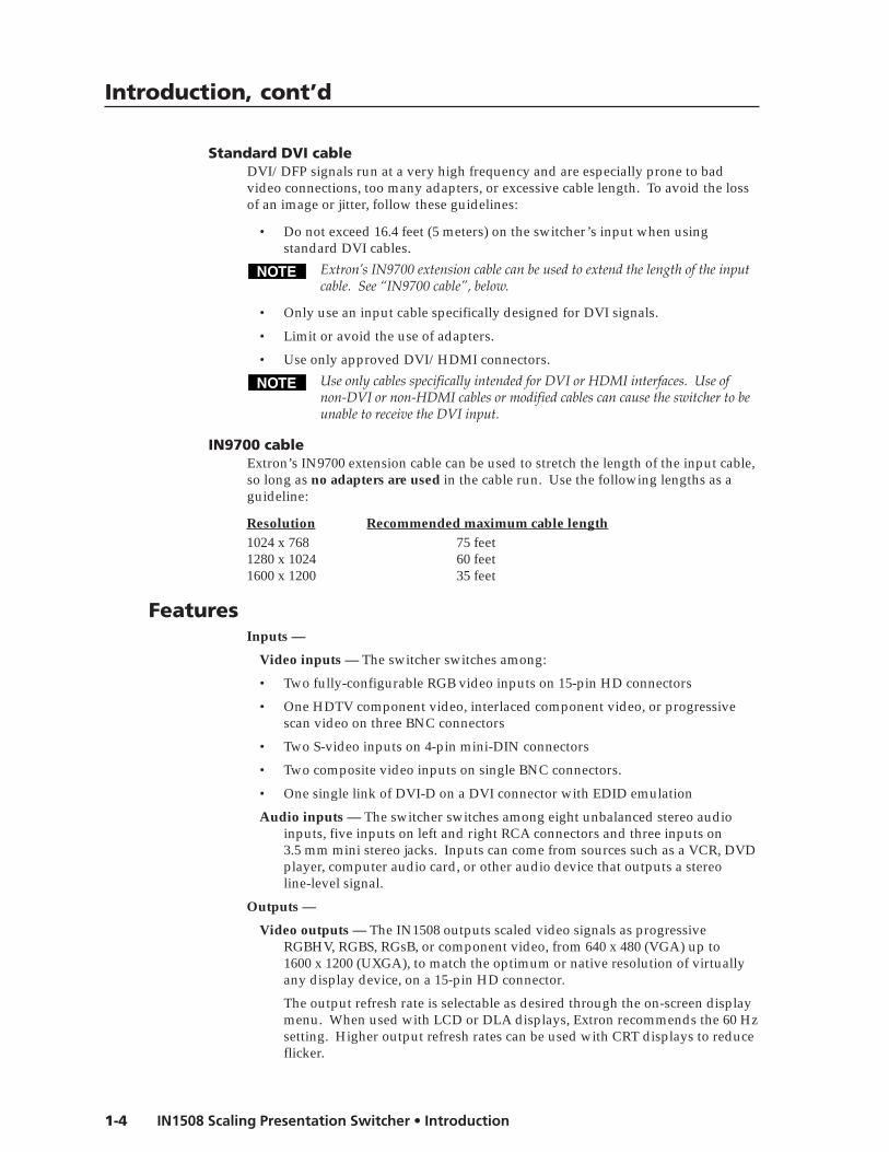
Standard DVI cableDVI/DFP signals run at a very high frequency and are especially prone to badvideo connections, too many adapters, or excessive cable length. To avoid the lossof an image or jitter, follow these guidelines:
• Do not exceed 16.4 feet (5 meters) on the switcher’s input when usingstandard DVI cables.
Extron’s IN9700 extension cable can be used to extend the length of the inputcable. See “IN9700 cable”, below.
• Only use an input cable specifically designed for DVI signals.
• Limit or avoid the use of adapters.
• Use only approved DVI/HDMI connectors.
Use only cables specifically intended for DVI or HDMI interfaces. Use ofnon-DVI or non-HDMI cables or modified cables can cause the switcher to beunable to receive the DVI input.
IN9700 cableExtron’s IN9700 extension cable can be used to stretch the length of the input cable,so long as no adapters are used in the cable run. Use the following lengths as aguideline:
Resolution Recommended maximum cable length1024 x 768 75 feet1280 x 1024 60 feet1600 x 1200 35 feet
FeaturesInputs —
Video inputs — The switcher switches among:
• Two fully-configurable RGB video inputs on 15-pin HD connectors
• One HDTV component video, interlaced component video, or progressivescan video on three BNC connectors
• Two S-video inputs on 4-pin mini-DIN connectors
• Two composite video inputs on single BNC connectors.
• One single link of DVI-D on a DVI connector with EDID emulation
Audio inputs — The switcher switches among eight unbalanced stereo audioinputs, five inputs on left and right RCA connectors and three inputs on3.5 mm mini stereo jacks. Inputs can come from sources such as a VCR, DVDplayer, computer audio card, or other audio device that outputs a stereoline-level signal.
Outputs —
Video outputs — The IN1508 outputs scaled video signals as progressiveRGBHV, RGBS, RGsB, or component video, from 640 x 480 (VGA) up to1600 x 1200 (UXGA), to match the optimum or native resolution of virtuallyany display device, on a 15-pin HD connector.
The output refresh rate is selectable as desired through the on-screen displaymenu. When used with LCD or DLA displays, Extron recommends the 60 Hzsetting. Higher output refresh rates can be used with CRT displays to reduceflicker.

1-5IN1508 Scaling Presentation Switcher • Introduction
Audio outputs — The switcher provides an unbalanced line level signal that isidentical to the input signal. This output can drive any line level compatibleaudio unit, or a local device such as powered speakers.
Video output resolutions — The IN1508 outputs an image scaled up to thefollowing output resolutions:
• 640 x 480 (VGA) at 50 Hz, 60 Hz, and 75 Hz
• 800 x 600 (SVGA) at 50 Hz, 60 Hz, and 75 Hz
• 852 x 480 at 50 Hz and 60 Hz
• 1024 x 768 (XGA) at 50 Hz, 60 Hz, and 75 Hz
• 1280 x 768 at 60 Hz
• 1280 x 800 at 50 Hz and 60 Hz
• 1280 x 1024 (SXGA) at 50 Hz, 60 Hz, and 75 Hz
• 1024 x 852 at 50 Hz, 60 Hz, and 75 Hz
• 1024 x 1024 at 50 Hz, 60 Hz, and 75 Hz
• 1366 x 768 (wide XGA) at 50 Hz, 60 Hz, and 75 Hz
• 1365 x 1024 (plasma) at 50 Hz, 60 Hz, and 75 Hz
• 1400 x 1050 at 50 Hz and 60 Hz
• 1440 x 900 at 60 Hz and 75 Hz
• 1600 x 1200 (UXGA) at 50 Hz and 60 Hz
• 1680 x 1050 at 60 Hz
• 720 x 480 (HDTV 480p) at 60 Hz
• 720 x 576 (HDTV 576p) at 50 Hz
• 1280 x 720 (HDTV 720p) at 50 Hz and 60 Hz
• 1920 x 1080 (HDTV 1080i ) at 50 Hz and 60 Hz
• 1920 x 1080 (HDTV 1080p) at 60 Hz
Seamless Switching — The IN1508 provides a seamless transition between scaledlow resolution video inputs (inputs 1 through 4 [or inputs 1 through 5 ifinput 5 is configured as interlaced component video]) and the high resolutioninputs (inputs 6 and 7 [or inputs 5 through 7 if input 5 is configured asprogressive component video or HDTV]).
Picture-in-picture — One input from either the low resolution (interlacedcomponent, S-video, and composite video) video inputs or the highresolution (VGA, progressive component, and DVI) video inputs can beselected as the primary picture. A second high resolution or low resolutioninput can be selected as the secondary picture. The secondary picture isdisplayed in a user-determined area of the output image. The primary andsecondary picture can be swapped with a touch of a button.

Introduction, cont’d
IN1508 Scaling Presentation Switcher • Introduction1-6
Inverse 3:2 pulldown detection for NTSC video sources and 2:2 film detection forPAL video sources — This advanced film mode processing feature helpsmaximize image detail and sharpness for video sources that originated fromfilm. When film is converted to NTSC video, the film frame rate has to bematched to the video frame rate in a process called 3:2 pulldown. Jaggies andother image artifacts can result if conventional deinterlacing techniques areused on film-source video. The IN1508’s advanced film mode processingrecognizes signals that originated from film. The switcher then applies videoprocessing algorithms that optimize the conversion of video that was madewith the 3:2 pulldown process. This results in richly detailed images withsharply defined lines.
A similar process is used for PAL film-source video.
Quad-standard decoding — The IN1508’s video decoder provides accurate videodecoding of composite video and S-video in the NTSC, PAL, SECAM, andNTSC 4.43 standards. The advanced 3-line adaptive comb filter that decodescomposite video reduces cross-color interference and hanging dots whilemaintaining maximum image bandwidth and detail.
Picture controls — A wide variety of picture controls are available for fine pictureadjustments:
• Position
• Size
• Brightness and contrast
• Color and tint
• Sharpness
Once these adjustments are made, the settings are stored in non-volatilememory and automatically recalled when the same input source is selectedagain.
On-screen menus — The switcher puts its menu displays on the output videostream, for display by the output monitor or projector. The menu systemprovides easy control of video adjustments. The on-screen menus also makeit easy to verify and adjust advanced settings such as output signalresolution, refresh rate, sync format, and the reset to factory defaultsfunction.
Audio follow — When an input is selected on the front panel, the audio inputfollows its corresponding video input signal (audio follow). Under RS-232control, the audio input can be switched to follow either the main windowselection or the PIP window selection.
Operational flexibility — Operations such as input and scaling selection andpicture controls can be performed on the front panel or over the RS-232 link.The RS-232 links allow remote control via a PC or control system.
• Front panel control — The switcher’s front panel controller and on-screen menus support individual input selection, resolution selection,volume control, and complete configuration of the switcher.
• Infrared remote control — The switcher includes an Infrared (IR) remotecontrol that duplicates all of the front panel functionality and someRS-232 functionality.
• Simple Instruction Set (SIS) commands — The remote control protocoluses Extron’s SIS commands for easy programming and operation.

1-7IN1508 Scaling Presentation Switcher • Introduction
Freeze mode — Provides a high quality still image for applications that requireclose examination of a specific video frame.
Blank mode — Suppresses the output video image. Blank silences the R, G, and Bvideo outputs but the switcher still outputs sync. This ensures that theoutput device does not lose sync lock. Blank mode operates for video andRGB signals that are processed by the scaling circuitry. On-screen displaysare not blanked.
Rack mountable — The 1U high switcher can be mounted in any conventional 19"wide rack using the included rack mounting brackets.
Power — The 100 VAC to 240 VAC, auto-switchable, internal power supply of theIN1508 provides worldwide power compatibility.

Introduction, cont’d
IN1508 Scaling Presentation Switcher • Introduction1-8

IN1508 Scaling Presentation Switcher
2Chapter Two
Installation
Mounting the Switcher
Cabling and Rear Panel Views
Remote Control Battery Installation
Configuration

Installation, cont’d
IN1508 Scaling Presentation Switcher • Installation2-2
Installation
Mounting the SwitcherThe IN1508 comes with rubber feet and a set of rack mounting brackets.
Tabletop useAttach a self-adhesive rubber foot to each corner of the bottom of the switcher.
Rack mounting
UL requirementsThe following Underwriters Laboratories (UL) requirements pertain to theinstallation of the switcher into a rack (figure 2-1).
1. Elevated operating ambient temperature — If installed in a closed or multi-unit rack assembly, the operating ambient temperature of the rackenvironment may be greater than room ambient temperature. Therefore,install the MLC in an environment compatible with the maximum ambienttemperature (Tma = +122 °F, +50 °C) specified by Extron.
2. Reduced air flow — Install the equipment in a rack so that the amount of airflow required for safe operation of the equipment is not compromised.
3. Mechanical loading — Mount the equipment in the rack so that a hazardouscondition is not achieved due to uneven mechanical loading.
4. Circuit overloading — Connect the equipment to the supply circuit andconsider the effect that circuit overloading might have on overcurrentprotection and supply wiring. Appropriate consideration of equipmentnameplate ratings should be used when addressing this concern.
5. Reliable earthing (grounding) — Maintain reliable grounding of rack-mounted equipment. Pay particular attention to supply connections otherthan direct connections to the branch circuit (e.g. use of power strips).
Mounting instructionsRack mount the switcher as follows:
1. Attach the rack mounting brackets to the switcher with the supplied eight #8machine screws (figure 2-1).
2. Insert the switcher into the rack, aligning the holes in the mounting bracketwith those in the rack.
100-240V 50-60Hz I
N
P
U
T
VID
VID
YC
Y
B-Y
C-Y
RGB
DVI
1
2
4
5
3
L
2
3
4
5
6
7
R
AUDIO INPUT
L
A
B
R
OUTPUT
L
R
OUTPUT
RGB
Y, B-Y, C
-Y
8
7
RGB
6
LISTED
1T23
I.T.E.
C
U S
Rack-mountBracket
Figure 2-1 — Mounting the switcher

2-3IN1508 Scaling Presentation Switcher • Installation
3. Secure the switcher to the rack using the supplied machine screws.
Cabling and Rear Panel ViewsAll connectors are on the rear panel (figure 2-2).
50/60Hz
100-240V 50-60Hz
I
N
P
U
T
VID
VID
YC
YC
Y B-Y R-Y RGB DVI
RS-232
1
2 4 5
3
L
1 2 3 4 5 6
7R
AUDIO INPUT
LA
B
R
OUTPUT
L R
OUTPUT
RGBY, B-Y, R-Y
8
7 8
RGB
LISTED1T23I.T.E.
C U S
6
2 5 98431 6 12117 10
Figure 2-2 — IN1508 rear panel connectors
Power connection1 AC power connector — Plug a standard IEC power cord into this connector
to connect the switcher to a 100 to 240 VAC, 50 Hz or 60 Hz power source.
Video connections2 Input 1 and Input 2 composite video connectors — Connect
composite video sources to these female BNC connectors.
3 Input 3 and Input 4 S-video connectors — Connect S-video sourcesto these 4-pin mini DIN connectors.
4 Input 5 component video connectors — Connect aprogressive or interlaced component video (Y, B-Y, R-Y)source to these female BNC connectors.
5 Input 6 and Input 7 RGB video connectors — Connect RGBHVor RGBS sources to these female 15-pin HD connectors.
6 Input 8 DVI video connector — Connect a single link ofDVI-D direct digital video to this female DVI connector. Thisconnector supports only a digital DVI source.
With the proper adapters, the IN1508 can also be used with HDMI signals.
7 Video output 15-pin HD connectors — Connect an RGB videoor progressive/HDTV component video display to this female15-pin HD connector.
I
N
P
U
T
VID
VID
1
2
YC
YC
4
3YC
Y B-Y R-Y5
RGB7
RGB
6
DVI8
OUTPUT
RGBY, B-Y, R-Y

Installation, cont’d
IN1508 Scaling Presentation Switcher • Installation2-4
Audio connections8 Input 1 through Input 5 connectors — Connect unbalanced stereo or
mono audio sources (such as DVD players or VCRs) to these pairs (leftand right) of RCA connectors for audio input.
9 Input 6 through Input 8 connectors — Connect unbalanced stereo audiosources (such as computers) to these 3.5 mm mini stereo jacks for unbalancedaudio input. Figure 2-3 shows how to wire the audio jack.
Sleeve ( )
Ring (R)
Tip (L)
Figure 2-3 — Input 6 through input 8 audio connector wiring
10 Output A connector — Connect an audio device, such as an amplifier orpowered speakers, to these left and right RCA connectors.
11 Output B connector — Connect an audio device, such as powered speakers,to this 3.5 mm, 5-pole captive screw connector for balanced or unbalancedaudio output.
Figure 2-4 shows how to wire the captive screw audio connector. Theconnector is included with the switcher, but you must obtain the cable. Insertthe wires into the appropriate openings in the captive screw connector.Tighten the screws on top to fasten the wires.
CAUTION Connect the sleeve(s) to ground ( ). Connecting the sleeve(s) to anegative (-) terminal will damage audio output circuits.
Do not tin the wires!
Unbalanced Stereo Output
TipNO GROUND HERE.
Sleeve(s)Tip
NO GROUND HERE.
Balanced Stereo Output
TipRing
TipRing
LR
LR
Left
Right
Left
Right
Figure 2-4 — Wiring the audio output connector
The length of exposed wires is critical. The ideal length is 3/16” (5 mm).
• If the stripped section of wire is longer than 3/16”, the exposed wires maytouch, causing a short circuit between them.
• If the stripped section of wire is shorter than 3/16”, wires can be easilypulled out even if tightly fastened by the captive screws.
By default, the audio output follows the video switch.
L
R

2-5IN1508 Scaling Presentation Switcher • Installation
RS-232 connection12 Remote port — Connect a host device, such as a computer or touch panel
control, to the IN1508 switcher via this 9-pin D connector for serial RS-232control (figure 2-5).
RS-232 FunctionPin
123456789
—TXRX—
Gnd————
Not usedTransmit dataReceive dataNot usedSignal groundNot usedNot usedNot usedNot used
5 1
9 6Female
Figure 2-5 — Remote port pin assignments
See chapter 4, “Serial Communications”, for definitions of the SIS commands.
Remote Control Battery InstallationInstall two AAA batteries as shown (figure 2-6).
Figure 2-6 — Battery installation
ConfigurationThe switcher must be configured for the video that is connected to input 5 and forthe output video device. Configuration can be accomplished using either the frontpanel controls, the IR remote control, or the Simple Instruction Set. See chapter 3,“Operation”, and chapter 4, “Serial Communications”.

Installation, cont’d
IN1508 Scaling Presentation Switcher • Installation2-6

IN1508 Scaling Presentation Switcher
3Chapter Three
Operation
Front Panel Controls and Indicators
Remote Control Buttons
Operations
Optimizing the Video
Optimizing the Audio
Troubleshooting

Operation, cont’d
IN1508 Scaling Presentation Switcher • Operation3-2
Operation
Front Panel Controls and IndicatorsAll of the switcher’s controls are on the front panel (figure 3-1). Many controls areduplicated on the IR remote control (figure 3-8 on page 3-7). Front panel LEDsprovide graphic indication of some of the basic system functions. For morecomplex tasks, such as system configuration, the switcher has a menu system thatis operated by using the front panel or IR remote control buttons. The menusystem reports via an on-screen display on the connected output device (figure 3-2).
INPUT OUTPUT RATE PIP SCALING PRESENTATION SWITCHERIR
IN1508 PICTURE CONTROLS
VGA
SVGA
XGA
SXGA
ON 7 6 5 4 3 2 1 SWAP 8 CENTER SIZE CONT/ BRT
COL/ TNT MENU ENTER
1024x852
1024x1024
1366x768
1365x1024
UXGA
720p
1080i
1080p
1 2 3 4 5 6 7 8
Figure 3-1 — IN1508 video switcher and switcher front panel
INPUT
OUTPUT RATE
PIP
DIGITAL VIDEO SCALER
IR
IN1508
PICTURE CONTROL
VGA
SVGA
XGA
SXGA
ON
4
3
2
1
SWAPCENTER
SIZE
CONT/
BRT
COL/
TNT
MENU
ENTER
1024x852
1024x1024
1366x768
1365x1024
UXGA
720p
1080i
1080p
Menu Controls15HD
Menu Controls
PICTURE
OUTPUT
INPUT
ADVANCEDAUDIO Output Volume
Input Gain/Atten
Audio Delay
ASPECT
RATIO
SIZE
ENTER
MENU
CENTER
CONT/
BRT
COL/TINT
VIDEOMUTE
AUDIO
MUTE
A/VMUTE
ZOOM
PAN
5
6
ON/OFFPIP
SWAP
7
8
IN1508
REMOTE
ASPECT
RATIO
SHARP
PHASE
FREEZE
EXTRON ELECTRONICSIN1508 SCALING PRESENTATION SWITCHER
30°
Figure 3-2 — Menu system display
Infrared sensor1 Infrared remote sensor — This sensor receives infrared (IR) signals from the
included IN1508 remote control. The IR remote control must be pointedwithin 30 degrees of this sensor (figure 3-2) for best results.
See “Remote Control Buttons”, later in this chapter, for operation of theremote control.
The switcher’s IR receiver can be disabled to avoid conflicts with otherremotes. See the IR receiver enable SIS command in chapter 4, “SerialCommunications” to disable the IR receiver.

3-3IN1508 Scaling Presentation Switcher • Operation
Input controls2 Input buttons — The Input 1 through Input 8 buttons (figure 3-3) select the
associated video input to scale and output. The switch can be a cut or a fade,depending on the switch mode; see “Fade Switch selection box”, on page 3-24.Audio always follows (switches with) the front panel video selection.
INPUT
7654321 8
Figure 3-3 — Input selection buttons and LEDs
If the picture-in-picture (PIP) feature is turned on (the PIP On LED, 4 , islit), the input buttons select an input for either the primary (main) window orthe secondary (PIP) window. If the PIP feature is turned off, the input buttonsselect the main output only. See “Input selection operation” on page 3-10 fordetails.
If the PIP feature is turned on, when an input is selected, the audio associatedwith that input in the PIP window is muted. The audio does not becomeunmuted until either:
• It is swapped to the main window.
• A Simple Instruction Set Audio follow source command has been issuedto configure the switcher to make the audio follow the PIP window. Seechapter 4, “Serial Communications”.
Input LEDs — The Input 1 through Input 8 LEDs indicate the selected videoand audio input(s).
An Input LED that is lit green indicates the primary (main) output.
An Input LED that is lit red indicates the secondary output (the input that isdisplayed in the PIP window).
No input LED lights red if the PIP feature is turned off.

Operation, cont’d
IN1508 Scaling Presentation Switcher • Operation3-4
Output Rate selection3 Output Rate button — The Output Rate button (figure 3-4) cycles through
the available output screen resolutions. Use this button to select the “sweetspot” resolution of the connected video display device. The switcherdefaults to a refresh rate of 60 Hz with each resolution selection using theOutput Rate button.
Eight IN1508 output resolutions are not available from the front panel. Theseeight resolutions can be selected using the menu system (see “Resolutionselection box”, on page 3-21) and SIS commands (see chapter 4, “SerialCommunications”). The eight output resolutions not available from the frontpanel are:
• 852 x 480 • 1400 x 1050 • 1280 x 768 • 1280 x 800• 1440 x 900 • 1680 x 1050 • 480p • 576p
OUTPUT RATE
VGA
SVGA
XGA
SXGA
1024x852
1024x1024
1366x768
1365x1024
UXGA
720p
1080i
1080p
Pressbutton (P)
P
P
P
P
P
P
P
P
P
P P P
Figure 3-4 — Output Rate buttons
The Output Rate LEDs indicate the selected resolution.
If any of the rates not available from the front panel are selected using themenu system or SIS commands, no Output Rate LED is lit.
The Output Rate button allows you to select the resolution only; the refreshrate defaults to 60 Hz for each front panel resolution selection. You can selecta different refresh rate using the menu system; see “Refresh Rate selection box”later in this chapter for details.
There is a 1-second delay between selecting an output resolution from the frontpanel (the desired Output Rate LED lights) and the selected change takingeffect. This ensures that the screen does not try to change resolutions whileyou cycle through the available resolutions to the desired setting.
The switcher reports the selected resolution for approximately 3 seconds onthe connected output display.

3-5IN1508 Scaling Presentation Switcher • Operation
Picture-in-Picture controls4 PIP buttons —
PIP
ON SWAP
Figure 3-5 — Picture-in-Picture buttons
On button — The PIP On button toggles the PIP function on and off.
If you press and hold the PIP On button while you apply power to theswitcher, the switcher toggles the output signal type between RGB andprogressive component video. If an RGB signal type (RGBHV, RGBS, orRGsB) was selected the last time the switcher was powered, the signal typeswitches to component. If component video was selected, the signal typeswitches to RGB.
The audio breakaway switching function, normally available under RS-232control only, is not available when the PIP function is on.
On LED — When lit, the PIP On LED indicates that the switcher’s PIPfunction is on.
Swap button — The PIP Swap button toggles the primary and secondarypictures between the main image and the PIP window.
With regard to the PIP function, there are two groups of inputs:
• Low resolution — Inputs 1 through 4 (and input 5 if it is configured asinterlaced component video; see “Input 5 selection” on page 3-18)
• High resolution — Inputs 6 through 8 (and input 5 if it configured asprogressive component video/HDTV; see “Input 5 selection” onpage 3-18)
The PIP function toggles between the selected input in each group. The PIPfunction cannot toggle between two inputs in the same group.
The size of the PIP window is set in the menu system, see “PIP Mode selectionbox”, on page 3-24, for details. The position of the PIP window is set with thecentering adjustment; see “Picture adjustments”, on page 3-25, for details.
If PIP mode is off (the PIP Mode On LED is off), the Swap function continuesto work, toggling between the most recently selected low-resolution input andthe most recently selected high-resolution input. Unlike when PIP mode is on,however, the input that is replaced in the main window is not displayed in thePIP window.
Operation, cont’d
IN1508 Scaling Presentation Switcher • Operation3-6
Picture Controls buttonsPICTURE CONTROLS
CENTER SIZECONT/BRT
COL/TNT
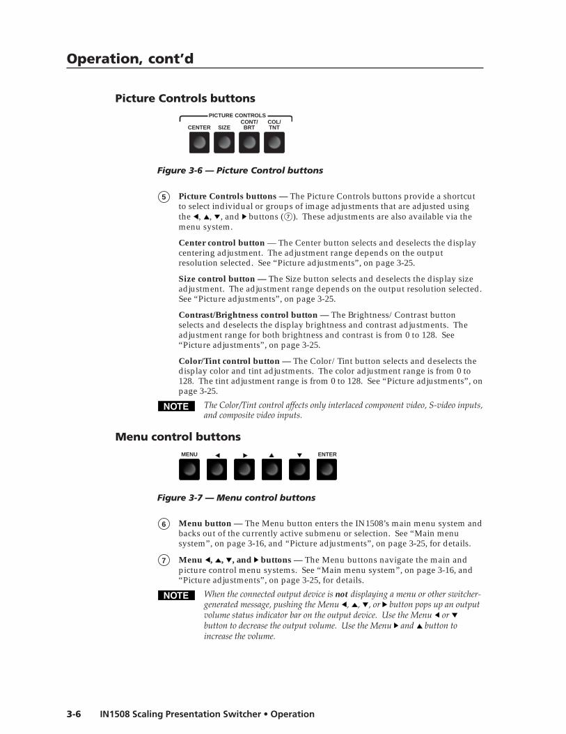
Figure 3-6 — Picture Control buttons
5 Picture Controls buttons — The Picture Controls buttons provide a shortcutto select individual or groups of image adjustments that are adjusted usingthe , , , and buttons ( 7 ). These adjustments are also available via themenu system.
Center control button — The Center button selects and deselects the displaycentering adjustment. The adjustment range depends on the outputresolution selected. See “Picture adjustments”, on page 3-25.
Size control button — The Size button selects and deselects the display sizeadjustment. The adjustment range depends on the output resolution selected.See “Picture adjustments”, on page 3-25.
Contrast/Brightness control button — The Brightness/Contrast buttonselects and deselects the display brightness and contrast adjustments. Theadjustment range for both brightness and contrast is from 0 to 128. See“Picture adjustments”, on page 3-25.
Color/Tint control button — The Color/Tint button selects and deselects thedisplay color and tint adjustments. The color adjustment range is from 0 to128. The tint adjustment range is from 0 to 128. See “Picture adjustments”, onpage 3-25.
The Color/Tint control affects only interlaced component video, S-video inputs,and composite video inputs.
Menu control buttonsMENU ENTER
Figure 3-7 — Menu control buttons
6 Menu button — The Menu button enters the IN1508’s main menu system andbacks out of the currently active submenu or selection. See “Main menusystem”, on page 3-16, and “Picture adjustments”, on page 3-25, for details.
7 Menu , , , and buttons — The Menu buttons navigate the main andpicture control menu systems. See “Main menu system”, on page 3-16, and“Picture adjustments”, on page 3-25, for details.
When the connected output device is not displaying a menu or other switcher-generated message, pushing the Menu , , , or button pops up an outputvolume status indicator bar on the output device. Use the Menu or button to decrease the output volume. Use the Menu and button toincrease the volume.

3-7IN1508 Scaling Presentation Switcher • Operation
8 Enter button — The Enter button:
• Activates a highlighted submenu or function in the IN1508 main menusystem.
• Exits a slider-type status indicator bar control.
• Saves a changed value in a selection box control.
See “Main menu system”, on page 3-16, and “Picture adjustments”, onpage 3-25, for details.
Remote Control ButtonsTo control the switcher with the hand-heldIN1508 Remote control (figure 3-8), aim the hand-heldunit at the IR detector on the switcher and press thedesired buttons on the remote. The maximumoperating range is 30 feet.
9 Picture-In-Picture (PIP) buttons — The PIPbuttons function identically to the front panel PIPbuttons. See “Picture-in-picture controls” and 4 ,on page 3-5.
On/Off button — The PIP On/Off button togglesthe PIP function on and off. When lit, the frontpanel PIP On LED indicates that the switcher’spicture-in-picture function is on.
Swap button — The PIP Swap button toggles theprimary and secondary pictures between the mainimage and the PIP window.
If PIP mode is off (the front panel PIP Mode OnLED is off), the Swap function continues towork, toggling between the most recentlyselected low-resolution input and the mostrecently selected high-resolution input. Unlikewhen PIP mode is on, however, the unselectedinput is not displayed in a PIP window.
10 Input Selection buttons — The Input Selectionbuttons select an input to scale and output. Thefront panel Input LEDs indicate the selected input.
The Input Selection buttons function identically to the front panel Inputbuttons. See “Input controls” and 2 on page 3-3.
11 Mute/Freeze buttons — The Mute and Freeze buttons blank the screenand/or silence the audio and freeze the video. Press the buttons to toggle themutes and freeze mode on and off.
Video Mute — The Video Mute button switches the output to a blank screen.The blank screen is deselected when a new input is selected. On-screendisplays are still available when the video is muted.
Video mute mutes the video signals only. Separate H and V sync, compositesync, or sync-on-green (depending on the output format selected) is alwaysoutput to ensure that the connected display does not lose sync.
Audio Mute — The Audio Mute button silences the audio output. The audiomute is deselected when a new input is selected.
SIZE
ENTERMENU
CENTERCONT/
BRTCOL/TINT
VIDEOMUTE
AUDIOMUTE
A/VMUTE
5 6
ON/OFFPIP
SWAP
7 8
IN1508REMOTE
ZOOM PAN
SHARP PHASE
ASPECTRATIO
FREEZE
12
13
10
9
11
Figure 3-8 — IRremote control

Operation, cont’d
IN1508 Scaling Presentation Switcher • Operation3-8
A/V Mute — The A/V Mute button switches the output to a blank screen andsilences the audio output. The blank screen and muted audio are deselectedwhen a new input is selected.
Freeze — The Freeze button toggles the freeze feature on and off. Freezestops the image at the moment you activate the feature and outputs a stillimage. Freeze is deselected when a new input is selected.
12 Menu buttons — The Menu buttons function identically to the front panelMenu buttons. See “Menu control buttons” and 6 , 7 , and 8 , starting onpage 3-6.
Menu button — The Menu button enters the main menu system and backsout of the currently active submenu or selection. See “Main menu system”and “Picture adjustments”, later in this chapter, for details.
, , , and buttons — The , , , and buttons navigate the main andpicture control menu systems. See “Main menu system”, on page 3-16, and“Picture adjustments”, on page 3-25, for details.
When the connected output device is not displaying a menu or other switcher-generated message, pushing the Menu control , , , or button pops up anoutput volume status indicator bar on the output device. Use the Menucontrol or button to decrease the output volume. Use the Menu control and button to increase the volume.
Enter button — The Enter button:
• Activates a highlighted submenu or function in the IN1508 main menusystem.
• Exits a slider-type status indicator bar control.
• Saves a changed value in a selection box control.
See “Main menu system”, later in this chapter, for details.
13 Picture control buttons — The picture control buttons are a short cut toselecting individual or groups of image status indicator bar displays that canbe adjusted using the , , , and buttons ( 14 ).
Size, Centering, Contrast/Brightness, and Color/Tint are also available fromthe front panel (see “Picture Controls buttons” and 5 on page 3-6).
Sharp and Phase are not available from the front panel picture control buttonsand are front-panel accessible only by navigating through the main menusystem.
Size button — The Size button selects and deselects the display sizeadjustment status indicator bars. The adjustment range depends on theoutput resolution selected.
Center button — The Center button selects and deselects the displaycentering adjustment status indicator bars. The adjustment range depends onthe output resolution selected.
Contrast/Brightness button — The Contrast/Brightness button selects anddeselects the display brightness and contrast adjustment status indicator bars.The adjustment range for both brightness and contrast is from 0 to 127.

3-9IN1508 Scaling Presentation Switcher • Operation
Color/Tint control button — The Color/Tint button selects and deselects thedisplay color and tint adjustment status indicator bars. The adjustment rangefor both color and tint is from 0 to 127.
The Color/Tint control affects only certain interalaced component video,composite video, and S-video, as shown in the following table.
Input type Color TintRGB No NoYUVp No NoRGBcvS No NoYUVi Yes NoNTSC S-video Yes YesPAL S-video Yes NoComposite NTSC Yes YesComposite Pal Yes No
Zoom button — The Zoom button selects and deselects the Zoom statusindicator bar. Use the and buttons to increase or decrease how muchzoom (enlargement) is applied to the image.
Pan button — The Pan button selects and deselects the horizontal and verticalPan status indicator bars. Use the and buttons to highlight the horizontal(H) or vertical (V) pan status indicator bar. Use the and buttons to pan leftand right or up and down.
Pan is available only for an image that has been zoomed in.
Aspect Ratio button — The Aspect Ratio button selects and deselects theaspect ratio setting selection box control. The aspect ratio options are 4:3 and16:9. The default is 4:3.
Sharp button — The Sharp button selects and deselects the sharpness settingadjustment status indicator bar. Sharpness uses variable filtering to affectinput picture detail and definition.
Phase button — The Phase button selects and deselects the phase settingadjustment status indicator bar. The phase adjustment range is 0 to 31.
OperationsThe following paragraphs detail the power-up process and then describe the menusystem, the picture, and the selection of the front panel security lockout.
PowerPower is applied when the power cord is connected to an AC source. When ACpower is applied, the switcher performs a self-test that cycles all of the front panelLEDs on and off from left to right. An error-free power up self-test sequence leavesthe selected input LED and the selected Output Rate LED on. If the picture-in-picture feature was turned on when the switcher was powered down, the PIP OnLED and a secondary input LED are also lit.
The selected input, the picture adjustments, and other current settings are saved innon-volatile memory. When power is applied, the latest configuration is retrieved.

Operation, cont’d
IN1508 Scaling Presentation Switcher • Operation3-10
Input selection operationEach of the eight inputs is assigned to one of two groups (see figure 3-9 on the nextpage):
• Low resolution — Inputs 1 through 4 (and input 5 if it is configured asinterlaced component video; see “Input 5 selection”, on page 3-18)
• High resolution — Inputs 6 through 8 (and input 5 if it configured asprogressive component video/HDTV; see “Input 5 selection”, on page 3-18)
Input selection acts differently, depending on whether PIP mode is on or off:
• PIP mode on — If the PIP mode is on (the PIP On LED is lit), pushing theinput button selects a new input for display in either the main window or thePIP window. The window in which the selected input is displayed dependson which group (high resolution or low resolution) the input is in. Theselected input replaces the previously selected input from the same group inwhichever window that input had been displayed.
° In figure 3-9, when you push the Input 3 button, input 3 replaces input 1in the PIP window.
° In figure 3-9, when you push the Input 8 button, input 8 replaces input 6in the main window.
• PIP mode off — If the PIP mode is off (the PIP On LED is off), pushing theinput button selects a new input for display in the main window.
Picture-in-picture mode operationThe two images displayed when the PIP feature is on (the PIP On LED is lit) mustcome from different input groups (one high resolution and one low resolution).
• If the primary input (the image displayed in the main window) is a high-resolution input, the secondary input (the image displayed in the PIPwindow) must be a low-resolution input (figure 3-9).
• If the primary input is a low-resolution input, the secondary input must be ahigh-resolution input (figure 3-9).
The PIP function toggles between the selected input in each group. In figure 3-9,when you push the Swap button:
• Input 3 replaces input 8 in the main window.
• Input 8 replaces input 3 in the PIP window.The PIP feature cannot toggle between two inputs in the same group.
If PIP mode is off (the PIP Mode On LED is off), the Swap function continuesto work, toggling between the most recently selected low-resolution input andthe most recently selected high-resolution input. Unlike when PIP mode is on,however, the input that is replaced in the main window is not displayed in thePIP window.

3-11IN1508 Scaling Presentation Switcher • Operation
INPUT OUTPUT RATE PIP IR
PICTURE CONTROLS
VGA
SVGA
XGA
SXGA
ON 7 6 5 4 3 2 1 SWAP
SWAP
8 CENTER SIZE CONT/ BRT
COL/ TNT MENU ENTER
1024x852
1024x1024
1366x768
1365x1024
UXGA
720p
1080i
1080p
3
Red
Press
8
Green
3
Green
Press
Red
8
50/60Hz
100-240V 50-60Hz
I
N
P
U
T
VID
VID
YC
YC
Y B-Y R-Y RGB DVI
1
2 4 5
3
L
1 2 3 4 5 6
7 R
AUDIO INPUT
L A
B
R
OUTPUT
L R
OUTPUT
RGB Y, B-Y, R-Y
8
7 8
RGB
6 LISTED 1T23 I.T.E.
C U S
DSS DVD
TV 4:3
PC Graphics 5:4
Input 1 Input 3 Input 6 Input 8
Low Resolution Input Group
High Resolution Input Group
In this example, input 5 is configured as progressive component video, so it is in the high resolution group.
NOTE
PIP On LED
Outputs Shown Below on 4:3 Monitor
RGB 192
PC
RGB 192
PC
2
4
6
8
10
20 50
100 1000
10k 75k
100k Output Voltage
Frequency (Hz)
Rolloff Uneven Frequency Response
Rolloff
2
4
6
8
10
20 50
100 1000
10k 75k
100k Output Voltage
Frequency (Hz)
Rolloff Uneven Frequency Response
Rolloff
2
4
6
8
10
20 50
100 1000
10k 75k
100k Output Voltage
Frequency (Hz)
Rolloff Uneven Frequency Response
Rolloff
SCALING PRESENTATION SWITCHER
IN1508
Figure 3-9 — PIP mode input selection and swap operations

Operation, cont’d
IN1508 Scaling Presentation Switcher • Operation3-12
Menu system operationFigure 3-10 shows a flowchart of the submenus in the main menu system. Eachsubmenu leads to a series of submenus or to “slider” type status indicator barcontrols that accomplish individual tasks or groups of tasks.
In figure 3-10, and all other flowcharts in this chapter, solid lines indicatescreen changes initiated by the operator. Dashed lines indicate screen changesthat are the result of a timeout function.
Size Size Size
Center Center Center
Aspect Aspect Aspect
Zoom Zoom Zoom
Pan Pan Pan
Freeze Freeze Freeze
Blank Blank Blank
PIP Mode PIP Mode PIP Mode
Swap Swap Swap
Fade Switch Fade Switch Fade Switch
Blue Mode Blue Mode Blue Mode
Reset Reset Reset
Menu
Enter
Enter
No menu
display
Menu Timeout
EXTRON ELECTRONICS IN1508 SCALING PRESENTATION SWITCHER
INPUT
ADVANCED
Advanced Advanced Advanced
Input 5 Input 5 Input 5
Enter PICTURE +45
+64
+64
+64
Sharpness Sharpness Sharpness
Color Color Color
Tint Tint Tint
Brightness Brightness Brightness
Contrast Contrast Contrast
+64
Resolution Resolution Resolution
Refresh Rate Refresh Rate Refresh Rate
Sync Polarity Sync Polarity Sync Polarity
Signal Type Signal Type Signal Type
Enter OUTPUT
Enter AUDIO
Input Gain/AttenInput Gain/AttenInput Gain/Atten
Output Volume Output Volume Output Volume
Audio Delay Audio Delay Audio Delay
Figure 3-10 — Menu system flowchart

3-13IN1508 Scaling Presentation Switcher • Operation
Menu button — Press the front panel or IR remote control Menu button to activatethe menu system or to back up one level from the currently selected submenuor selection. (For example, pressing the Menu button in the Picture submenuturns off the Picture submenu selections and the switcher displays the mainmenu only.)
, , , and buttons —
Press the front panel or IR remote control , , , and buttons to maneuveraround the menu system, highlighting submenus or selections or increasingand decreasing selected picture control settings.
Enter button — Press the front panel or IR remote control Enter button to:
• Activate a highlighted submenu or function in the IN1508 main menu system
• Exit a slider-type status indicator bar control
• Save a changed value in a selection box controlTo return to normal operation (no menus), let the switcher remain idle for20 seconds until the selected screen times out, or press the front panel or IRremote control Menu button repeatedly until the Main Menu is deselected.
Selection boxes and status indicator barsMost of the menu system selections are made using either on-screen selection boxcontrols (the top example in figure 3-11) or “sliding” status indicator bar controls(the bottom example in figure 3-11). The two types of controls operate differently.
Press Menu orto exit the screen.
ContrastContrastContrast
BrightnessBrightnessBrightness +96
+64
(0 to 128)
(0 to 128)Timeout
Changes take affect as youmove the slider controls.
Typical status indicator bar control
Typical selection box control
Change does not take affectuntil Enter is pressed toactivate the selection.
Return tohigher level
screen.
Timeout
RGBHV
RGsB
Y,B-Y,R-Y
RGBS
Push Menu or Enterto exit the screen.
Nomenu
display
Return tohigher level
screen.
Nomenu
display
Figure 3-11 — Selection box vs. status indicator bar operation
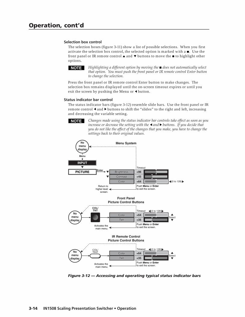
Operation, cont’d
IN1508 Scaling Presentation Switcher • Operation3-14
Selection box controlThe selection boxes (figure 3-11) show a list of possible selections. When you firstactivate the selection box control, the selected option is marked with a . Use thefront panel or IR remote control and buttons to move the to highlight otheroptions.
Highlighting a different option by moving the does not automatically selectthat option. You must push the front panel or IR remote control Enter buttonto change the selection.
Press the front panel or IR remote control Enter button to make changes. Theselection box remains displayed until the on-screen timeout expires or until youexit the screen by pushing the Menu or button.
Status indicator bar controlThe status indicator bars (figure 3-12) resemble slide bars. Use the front panel or IRremote control and buttons to shift the “slides” to the right and left, increasingand decreasing the variable setting.
Changes made using the status indicator bar controls take effect as soon as youincrease or decrease the setting with the and buttons. If you decide thatyou do not like the affect of the changes that you make, you have to change thesettings back to their original values.
ColorColorColor
TintTintTint +35
+64
Enter
COL/TNT
Front PanelPicture Control Buttons
Menu System
(0 to 128)
(0 to 128)
PICTURE
+64ColorColorColor
+45
+96BrightnessBrightnessBrightness
ContrastContrastContrast
Select
Nomenu
display
INPUT
Menu
Nomenu
display
ColorColorColor
TintTintTint +35
+64
IR Remote ControlPicture Control Buttons
(0 to 128)
Select
Nomenu
display
COL/TINT
Timeout
Timeout
Timeout
Return tohigher level
screen.
Push Menu or Enterto exit the screen.
Activates themain menu.
Activates themain menu.
Push Menu or Enterto exit the screen.
Push Menu or Enterto exit the screen.
Figure 3-12 — Accessing and operating typical status indicator bars

3-15IN1508 Scaling Presentation Switcher • Operation
Many status indicator bar controls can be activated in three ways (figure 3-12):
• By navigating to the status indicator bar via the menu system
• By pushing one of the front panel Picture Control buttons (such asColor/Tint)
• By pushing one of the IR remote control picture control buttons (such asColor/Tint)
Use the status indicator bars as follows:
1. If necessary, select the input that you want to adjust by pressing theappropriate input button.
2. For menu system operation:
a. Press the front panel or IR remote control Menu button. The on-screenMain Menu display appears on the connected monitors, overlaid on topof the output image.
b. Use the front panel or IR remote control and buttons to highlight thedesired submenu (such as Picture) and press the front panel or IR remotecontrol Enter button. The selected submenu or a group of statusindicator bars appears on the on-screen display.
c. If necessary, use the front panel or IR remote control and buttons tohighlight the desired status indicator bar on the selected submenu (suchas Color).
For picture control button operation:
a. Press the desired front panel or IR remote control picture control button.
b. If necessary, press and release the front panel or IR remote control and buttons to highlight the desired adjustment status indicator bar.
3. Press and release the front panel or IR remote control and buttons todecrease and increase the selected level by 1 step or press and hold thebuttons to flow through the adjustment range.
To make another adjustment to the same input, return to step 2.
To adjust another input, select that input. The switcher clears the on-screendisplays. Return to step 2.
4. Allow the on-screen display timeout to occur.

Operation, cont’d
IN1508 Scaling Presentation Switcher • Operation3-16
Main menu systemThe main menu includes the following submenus:
• Input submenu — Size, centering, and aspect ratio
• Picture submenu — Image quality adjustments
• Output submenu — Resolution, refresh rate, sync, and signal format
• Audio submenu — Input audio volume and audio delay
• Advanced submenu — Advanced options
Input submenuFigure 3-13 is a flowchart that shows an overview of the Input submenu, itsavailable selections, and their available settings. Use the front panel or IR remotecontrol and buttons to highlight the desired selection and press the Enterbutton.
Timeout
Timeout
Timeout
Timeout
Timeout
Timeout
Timeout
Timeout
Timeout
Timeout
Timeout
Nomenu
display
AUDIO
PICTURE
INPUT
OUTPUT
ADVANCED
MenuMenu
Timeout
Timeout
Timeout
Timeout
Menu
MenuMenu
Menu
Menu
Enter
Enter
Enter
Menu
Menu
Menu
Menu
Menu
Menu
H
Menu
H
Menu
V
Timeout
TimeoutV
SizeSize
PanPan
AspectAspect
AdvancedAdvanced
Input 5Input 5
Enter
Timeout
Timeout
Menu Enter
Menu
CenterCenter
ZoomZoomEnter
Enter
Menu
16:94:3
Menu
HDTVProgressiveInterlaced
EnterSelect
+480
+640
0
+8
V-StartV-Start
PhasePhase
H-StartH-Start
Active PixelsActive Pixels
Active LinesActive Lines
+127
Press Enter toselect a change.
Ranges for Advance selectionsvaries based on input appliedand output rate selected.
Press Enter toselect a change.
Total PixelsTotal Pixels +800
H
MenuZ
VSize
Pan
Aspect
Advanced
Input 5
Center
Zoom
V-Start
Phase
H-Start
Active Pixels
Active Lines
Total Pixels
Figure 3-13 — Input submenu flowchart

3-17IN1508 Scaling Presentation Switcher • Operation
Center selectionThe Center selection displays two status indicator bars that show, and allow you toadjust, the horizontal and vertical position of the main or picture-in-picture outputon the monitor.
If the PIP feature is turned off (the front panel PIP On LED is unlit), Center adjuststhe position of the main window.
If the picture-in-picture feature is turned on (the front panel PIP On LED is lit),Center adjusts the position of the PIP window.
The center adjustments do not crop the image or add blank lines.
Use the front panel or IR remote control and buttons to highlight the horizontal (H)or vertical (V) centering status indicator bar. Use the front panel or IR remotecontrol and buttons to move the image.
Size selectionThe Size selection displays two status indicator bars that show, and allow you toadjust, the horizontal and vertical size of the output. Use the front panel or IRremote control and buttons to highlight the horizontal (H) or vertical (V) sizestatus indicator bar. Use the front panel or IR remote control and buttons toincrease or decrease the size.
Zoom selectionThe Zoom selection displays a status indicator bar that allows you to adjust thezoom level of the output. Use the front panel or IR remote control and buttonsto increase or decrease how much zoom (enlargement) is applied to the image.
Pan selectionThe Pan selection displays two status indicator bars that allow you to pan (move)horizontally and vertically on a zoomed image. Use the front panel or IR remotecontrol and buttons to highlight the horizontal (H) or vertical (V) pan statusindicator bar. Use the front panel or IR remote control and buttons to pan leftand right or up and down.
Aspect ratio selectionThe Aspect ratio selection displays a selection box that shows the currently selectedaspect ratio and allows you to select another aspect ratio.
Use the front panel or IR remote control and buttons to highlight the desiredaspect ratio. Press the Enter button to change to the highlighted value. The defaultis 4:3.

Operation, cont’d
IN1508 Scaling Presentation Switcher • Operation3-18
Advanced screenThe Input submenu’s Advanced settings are a comprehensive set ofadjustments to optimize the switcher for non-standard video inputs. Mostusers do not encounter such signals. For those users who do, the switcherautomatically adjusts these settings. The switcher’s automatic adjustmentsare adequate for most inputs.
The Advanced screen provides a submenu of advanced selection options: activepixels, active lines, phase, horizontal and vertical start, and total pixels. Theseadvanced settings are rarely needed for standard video and computer videosignals, but provide the user with manual control over scaling parameters that areautomatic. The knowledgeable user may need to adjust these settings to optimizehis or her input signal(s). Possible reasons to adjust these settings include toleranceissues and nonstandard resolutions and frequencies. The settings are described inmore detail as part of the discussion on optimizing the video. See “Inputsubmenu’s Advanced selections”, on page 3-33.
To select one of the advanced settings, use the front panel or IR remote control or button to highlight the desired status indicator bar.
Input 5 selectionThe Input 5 selection displays a selection box that shows the currently assignedcomponent video format (interlaced [NTSC/PAL/SECAM], progressive [480p/576p],or HDTV [720p/1080i/1080p]) for input 5 and allows you to select a differentformat.
Use the front panel or IR remote control and buttons to highlight the desiredcomponent video format. Press the Enter button to change to the highlightedvalue. The default is progressive.
Picture submenuFigure 3-14 is a flowchart that shows an overview of the Picture submenu, itsavailable status indicator bars, and their available settings. Use the front panel orIR remote control and buttons to highlight the desired status indicator bar.
Timeout
Timeout
Timeout
Timeout
Menu
Timeout
Menu
Menu
Menu
Menu
TimeoutNo
menudisplay
AUDIO
PICTURE
INPUT
OUTPUT
ADVANCED
MenuMenu
Select
(0 to 128)
(0 to 128)
(0 to 128)
(0 to 128)
(0 to 128)
+64
+64
+64
+64
Sharpness
Color
Tint
Brightness
Contrast
Sharpness
Color
Tint
Brightness
Contrast
+64
Menu
Enter
Figure 3-14 — Picture submenu flowchart

3-19IN1508 Scaling Presentation Switcher • Operation
Brightness status indicator barThe Brightness status indicator bar shows, and allows you to adjust, the brightnesssetting for the selected input. Brightness adjusts the light intensity of the image onthe screen. Use the front panel or IR remote control and buttons to adjust thebrightness control through a range of 0 to 128. The default setting is 64.
Contrast status indicator barThe Contrast status indicator bar shows, and allows you to adjust, the contrastsetting for the selected input. Contrast adjusts the difference between the inputsignal’s brightest and darkest settings. Use the front panel or IR remote control
and buttons to adjust the contrast through a range of 0 to 128. At the minimumsetting, 0, the entire picture is shown at about the same brightness (gray). At themaximum setting, 128, there is a marked difference between the dark and lightareas of the image. The default setting is 45 for high resolution inputs and 59 forlow resolution inputs.
Color status indicator barThe color adjustment is available for interlaced component video, S-video, andcomposite video inputs only. See the table on page 3-9.
The Color status indicator bar shows, and allows you to adjust, the color setting forthe selected input. Color increases and decreases the color intensity of the picture.Use the front panel or IR remote control and buttons to adjust the contrastthrough a range of 0 to 128. At the minimum setting, 128, the switcher removesmost of the color. The default setting is 64.
Tint status indicator barThe tint adjustment is available for S-video and composite video inputs only.See the table on page 3-9.
The tint status indicator bar shows, and allows you to adjust, the tint setting.Tint is a relative measure of the amount of white in a given color and adjusts thepicture’s color toward red or green. Use the front panel or IR remote control and
buttons to adjust the tint control through a range of 0 to 128. Press the button toincrease the green (and decrease the red). Press the button to increase the red(and decrease the green). The default setting is 64.
Sharpness status indicator barThe Sharpness status indicator bar shows and allows you to adjust the sharpnesssetting. Sharpness uses variable filtering to affect input picture detail anddefinition. Use the front panel or IR remote control and buttons to increase ordecrease the sharpness filtering through a range of 0 to 128. The default settingis 64.

Operation, cont’d
IN1508 Scaling Presentation Switcher • Operation3-20
Output submenuFigure 3-15 is a flowchart that shows an overview of the Output submenu, itsavailable selections, and their available settings. Use the front panel or IR remotecontrol and buttons to highlight the desired selection and press the Enter button.
Timeout
Timeout
Timeout
Timeout
Timeout
Timeout
Timeout
Nomenu
display
AUDIO
PICTURE
INPUT
OUTPUT
ADVANCED
MenuMenu
Timeout
Timeout
Timeout
Timeout
Menu
Menu
Menu
Menu
Menu
Enter
Enter
Enter Menu
Menu
Menu
Enter
Enter
Timeout Timeout
1024 x 8521024 x 10241366 x 7681365 x 1024
800 x 600640 x 480
1024 x 768
1280 x 1024
644 x 480768 x 576
1600 x 12001400 x 1050
1280 x 7201920 x 10801920 x 1080
SVGAVGA
XGA1280 x 768
SXGA
480p576p
UXGA
720p1080i1080p
1440 x 9001680 x 10501280 x 800852 x 480
50 Hz 60 Hz 75 Hz
Sync H– / V+ Sync H– / V–
Sync H+ / V+ Sync H+ / V–
Resolution Resolution Resolution
Refresh Rate Refresh Rate Refresh Rate
Sync Polarity Sync Polarity Sync Polarity
Signal Type Signal Type Signal Type
Menu
Menu
Menu
Menu
Press Enter toselect a change.
Press Enter to select a change.
Press Enter to select a change.
Press Enter to select a change.
RGBHV
RGsB
Y,B-Y,R-Y
RGBS
Figure 3-15 — Output submenu flowchart

3-21IN1508 Scaling Presentation Switcher • Operation
Resolution selection boxThe front panel Output Rate button can also be used to select most resolutions,with the following exceptions:
• 852 x 480 • 1400 x 1050 • 1280 x 768 • 1280 x 800• 1440 x 900 • 1680 x 1050 • 480p • 576p
The Resolution selection boxidentifies the currently selectedoutput resolution and allowsyou to select a different outputresolution. The table at rightdefines the combinations ofresolutions and refresh ratesthat the switcher can output.
The default resolution is XGA.To select a different resolution,use the front panel or IR remotecontrol or button tohighlight the desired resolutionand press the Enter button.
Resolution andrefresh rate arecrucial variables foroptimum imagequality. For bestresults, set theswitcher output tomatch your display’scapabilities. See“Optimizing theVideo”, on page 3-30,for detailed guidelines for choosing the proper resolution and rate.
Refresh Rate selection boxThe front panel Output Rate button can be used to select the resolution, butevery front panel rate selection defaults to 60 Hz. Different refresh rates canbe selected only by using this screen or RS-232 control.
The Refresh Rate selection box identifies the currently selected output refresh rateand allows you to select a different rate.
To select a different rate, use the front panel or IR remote control or button tohighlight the desired resolution and press the Enter button.
Resolution and refresh rate are crucial variables for optimum image quality.For best results, set the switcher output to match the capabilities of yourdisplay. If necessary, see “Optimizing the Video”, on page 3-30, for detailedguidelines for choosing the proper resolution and rate.
Sync Polarity selection boxThe Sync Polarity selection box identifies the currently selected sync polarity andprovides the ability to select different sync polarities. The display or projector mayrequire video with positive or negative horizontal (H) and/or vertical (V) syncpolarity; consult the diplay or projector manual.
To select a different sync polarity, use the front panel or IR remote control or button to highlight the desired sync format and press the Enter button. The defaultsetting is H–/V–.
Resolution Aspectratio 50 Hz 60 Hz 75 Hz
640 x 480 VGA 4:3
800 x 600 SVGA 4:3
1024 x 768 XGA 4:3
1280 x 1024 SXGA 5:4
1024 x 852 4:3
1024 x 1024 1:1
1366 x 768 16:9
1365 x 1024 4:3
1400 x 1050 4:3
1280 x 720 720p 16:9
1920 x 1080 1080i 16:9
1920 x 1080 1080p 16:9
●
●
●
●
●
●
●
●
●
●
●
●
1280 x 768 16:9 ●
●
●
●
●
●
●
●
●
●
●
●
●
●
●
●
●
768 x 576 576p 4:3 ●
644 x 480 480p 4:3 ●
●
●
●
●
●
1680 x 1050 16:10
1280 x 800 16:10
852 x 480 4:3
●
●1440 x 900 16:10 ●
●●
● ●
1600 x 1200 UXGA 4:3

Operation, cont’d
IN1508 Scaling Presentation Switcher • Operation3-22
Signal Type selection boxThe Signal Type selection box identifies the currently selected output signal format(RGBHV, RGBS, RGsB, or progressive component video [Y, B-Y, R-Y]) and providesthe ability to select a different type. To select a different sync type, use the frontpanel or IR remote control or button to highlight the desired sync type andpress the enter button. The default setting is RGBHV.
Another way to select the output signal type is to press and hold the PIP Onbutton while you apply power to the switcher. This action toggles the signaltype between RGBHV and progressive component video. If RGB was selectedthe last time the switcher was powered, the signal type switches to componentvideo. If component video was selelected, the signal type switches to RGB.
Audio submenuFigure 3-16 shows an overview of the Audio submenu, its available selections, andtheir available settings. Use the front panel or IR remote control and buttons tohighlight the desired selection and press the Enter button.
Menu
Menu
Menu
Menu
Timeout
Enter
Menu
No menu
display
0 dB
Timeout
Timeout
Timeout Enter
Press Enter to select a change.
Menu
(-53 dB to +9 dB)
Menu
Menu
Off On
AUDIO Input Gain/AttenInput Gain/AttenInput Gain/Atten
Enter
Menu 100
(0 to 100)
Menu Enter Output Volume Output Volume Output Volume
Audio Delay Audio Delay Audio Delay
PICTURE
INPUT
OUTPUT
ADVANCED
Menu Menu
Timeout
Timeout
Timeout
Timeout
Timeout
Figure 3-16 — Audio submenu flowchart
Output Volume status indicator barThe Output Volume status indicator bar shows and allows you to adjust the audiooutput level (attenuation). Use the front panel or IR remote control and buttonsto increase or decrease the volume through a range of 0 to 100. The default settingis 100, that is, no attenuation (full volume).
Input Gain/Attenuation status indicator barThe Input Gain/Attenuation status indicator bar shows and allows you to adjustthe audio level (gain or attenuation) for the selected input. Use the front panel orIR remote control and buttons to increase or decrease the level frequenciesthrough a range of –53 dB to +9 dB. The default setting is 0 dB, no gain orattenuation.
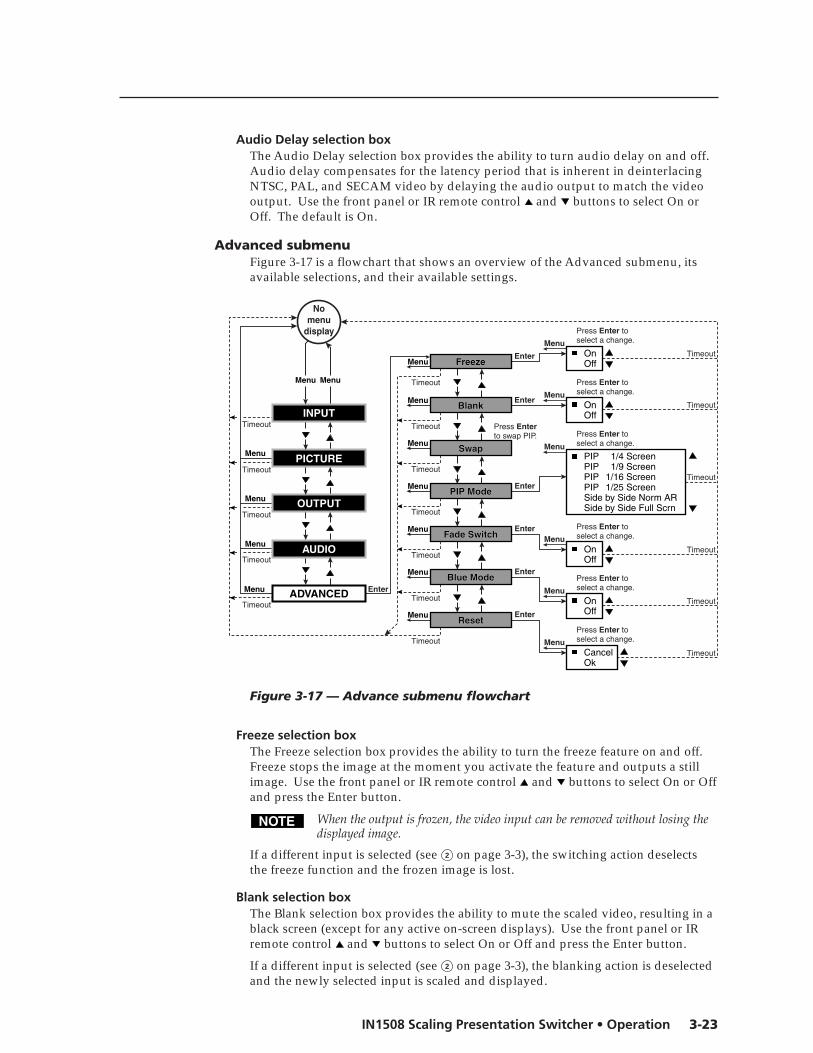
3-23IN1508 Scaling Presentation Switcher • Operation
Audio Delay selection boxThe Audio Delay selection box provides the ability to turn audio delay on and off.Audio delay compensates for the latency period that is inherent in deinterlacingNTSC, PAL, and SECAM video by delaying the audio output to match the videooutput. Use the front panel or IR remote control and buttons to select On orOff. The default is On.
Advanced submenuFigure 3-17 is a flowchart that shows an overview of the Advanced submenu, itsavailable selections, and their available settings.
Timeout
Timeout
Timeout
Timeout
Timeout
Timeout
Timeout
Timeout
Timeout
Timeout
Timeout
Timeout
Nomenu
display
AUDIO
PICTURE
INPUT
OUTPUT
ADVANCED
MenuMenu
Timeout
Timeout
Timeout
Timeout
Menu
Menu
Menu
Menu
Menu Enter
Enter
Enter
Menu
Menu
Menu
Menu
Menu
Menu
FreezeFreeze
BlankBlank
SwapSwap
PIP ModePIP Mode
Fade SwitchFade Switch
Timeout
Menu
Timeout
Menu
Enter
Menu
Blue ModeBlue Mode
ResetReset
OkCancel
OffOn
OffOn
PIP 1/9 ScreenPIP 1/16 Screen
PIP 1/4 Screen
Side by Side Norm ARSide by Side Full Scrn
PIP 1/25 Screen
Enter
OffOn
Menu
Enter
Menu
OffOn
Menu
Enter
Press Enter toselect a change.
Press Enter toselect a change.
Press Enter toselect a change.
Press Enter toselect a change.
Press Enter toselect a change.
Press Enter toselect a change.
Press Enterto swap PIP.
Figure 3-17 — Advance submenu flowchart
Freeze selection boxThe Freeze selection box provides the ability to turn the freeze feature on and off.Freeze stops the image at the moment you activate the feature and outputs a stillimage. Use the front panel or IR remote control and buttons to select On or Offand press the Enter button.
When the output is frozen, the video input can be removed without losing thedisplayed image.
If a different input is selected (see 2 on page 3-3), the switching action deselectsthe freeze function and the frozen image is lost.
Blank selection boxThe Blank selection box provides the ability to mute the scaled video, resulting in ablack screen (except for any active on-screen displays). Use the front panel or IRremote control and buttons to select On or Off and press the Enter button.
If a different input is selected (see 2 on page 3-3), the blanking action is deselectedand the newly selected input is scaled and displayed.

Operation, cont’d
IN1508 Scaling Presentation Switcher • Operation3-24
Swap selectionThe Swap selection toggles the primary and secondary inputs between the mainimage and the PIP window. Select swap by highlighting the Swap selection andpressing the Enter or button. Repeatedly press the Enter or button to togglebetween the main and PIP windows. Press the , , or button to deselect Swap,or allow the menu timeout (from the final button push) to clear the on-screendisplays. This on-screen display’s function is identical to pushing the front panelSwap button.
If PIP mode is off (the front panel PIP Mode On LED off), the Swap functioncontinues to work, toggling between the most recently selected low-resolutioninput and the most recently selected high-resolution input. Unlike when PIPmode is on, however, the unselected input is not displayed in a PIP window.
PIP Mode selection boxThe PIP Mode selection box displays the currently selected size and position for thepicture-in-picture window (if PIP mode is turned on) and allows you to selectanother size and position.
The two side-by-side options are available only via this menu or a SimpleInstruction Set command (see chapter 4, “Serial Communications”). If eitherside-by-side option is selected, the PIP size adjustment does not work.
Use the front panel or IR remote control and buttons to highlight the desiredsize and position and press the Enter button.
Fade Switch selection boxThe Fade Switch selection box provides the ability to select between cuts and fadeswhen you select a new input. A fade switch fades the output to black, switches tothe new input, and then fades in from black. A cut selects the new input with nomasking affect.
Use the front panel or IR remote control and buttons to select On for fadeswitches or Off for cuts and press the Enter button.
Blue Mode selection boxThe Blue Mode selection box provides the ability to turn the blue mode feature onand off. Blue mode is helpful in the setup of the color and tint of the incomingvideo signal. In the blue mode, only the sync and blue video signals are passed tothe display. Use the front panel or IR remote control and buttons to select Onor Off and press the Enter button.
Reset selection boxThe Reset selection box provides the ability to perform a system reset. Resetreturns the output rate selection to the XGA, 1024 x 768 at 60 Hz, setting; resets thepicture controls to their default values; sets all input audio levels to 0 dB; andselects input 1. Use the front panel or IR remote control and buttons to selectOk and press the Enter button to perform the reset or select Cancel and press theReset button to exit the screen without performing the reset.

3-25IN1508 Scaling Presentation Switcher • Operation
Performing a system reset from the front panelThe front panel reset is identical to the Esc zXXX SIS command (see chapter 4,“Serial Communications”) and the system reset that is available through the resetsystem (see “Reset selection box” earlier in this chapter). But the front panel resetdoes not require a connected computer or a connected monitor to view the on-screen displays.
A system reset returns the output rate selection to the XGA, 1024 x 768 at 60 Hz,setting; resets the picture controls to their default values; sets all input audio levelsto 0 dB; and selects input 1.
Reset the switcher to the factory default settings by pressing and holding theOutput Rate button while you apply AC power to the switcher (figure 3-18).
Power
VGA
SVGA
XGA
SXGA
Press and hold the Output Rate button while you apply power to the switcher.
After a brief delay, the switcher cycles all of the front panel LEDs on and off from left to right and then back to the left.Continue to hold the Output Rate button until the front panel cycle is complete.
Release the Output Rate button.
Figure 3-18 — Front panel system reset
Picture adjustmentsThe Picture Control buttons on the front panel and on the IR remote controlprovide shortcuts to the fine tuning adjustments for the selected input. All of theseadjustments are also available using the main menu system. When you press oneof the front panel or IR remote control picture control buttons, the on-screendisplay shows the corresponding image adjustment screen. The individualdescriptions in step 2 on page 3-27 identify the menu navigation required to reachthe screen using the main menu system.
Shortcuts for the centering, sizing, brightness, contrast, color, and tint adjustmentsare available from the front panel and the IR remote control (figure 3-19 onpage 3-26). Shortcuts for the zoom, pan, aspect ratio, sharpness, and pixel phaseshift are available from the IR remote control only (figure 3-20 on page 3-27).

Operation, cont’d
IN1508 Scaling Presentation Switcher • Operation3-26
NOTE The and buttons toggle between the top and bottom selection where applicable.The and buttons move the slider on the selected status bar indicator.
Nomenu
display
Press once Press again
= Front panel, = IR remote control
= PIP On LED lit, = PIP On LED unlit
CENTER
–OR–
CENTER
CONT/BRT
CENTER
SIZE
CONT/BRT
–OR–
COL/TINT
COL/TINT
–OR–
ContrastContrast
BrightnessBrightness +96
+64
(0 to 128)
(0 to 128)
SIZE
–OR–
SIZE
SIZE
–OR–
ColorColor
TintTint +64
+64
(0 to 128)
(0 to 128)
V
H
Timeout
Timeout
H StartH Start
V StartV Start +31
0
Timeout
Timeout
–OR–
Press againPress once
CENTER
Window CenterWindow Center
V
H
Timeout
Window SizeWindow Size
Image CenterImage Center
CENTER
–OR–
CENTER V
H
Timeout
Window CenterWindow Center
SIZE
Active PixelsActive Pixels
PhasePhase 0
+662
Active LinesActive Lines +532
Timeout
–OR–
SIZE
Image SizeImage Size
PIP Size PIP Size < 1/4 1/4 >
Contrast
Brightness
Color
Tint
H Start
V Start
Window Center
Window Size
Image Center
Window Center
Active Pixels
Phase
Active Lines
Image Size
PIP Size < 1/4 >
TimeoutPress to selecta different PIP size.
PIP
ON
PIP
ON
PIP
ON
PIP
ON
Figure 3-19 — Picture adjustments flowchart, front panel and IR remotecontrol buttons

3-27IN1508 Scaling Presentation Switcher • Operation
NOTE The and buttons toggle between the top and bottom selection where applicable. The and buttons move the slider on the selected status bar indicator.
No menu
display
= IR remote control
ASPECT RATIO
Sharpness Sharpness
Aspect Ratio 4:3 Aspect Ratio 4:3
+32
(0 to 63) SHARP
PHASE
Phase Phase +64
(0 to 128)
Zoom Zoom
Pan Pan
Sharpness
Aspect Ratio 4:3
Phase
Zoom
Pan V
H
Timeout
Timeout
Timeout
ZOOM
PAN
Timeout
Timeout Press to change the aspect ratio.
Figure 3-20 — Picture adjustments flowchart, IR remote control buttons
Color and Tint adjustments are available only for interlaced component video,S-video, and composite video inputs.
1. Press the appropriate picture adjustment button: centering (Center), sizing(Size), brightness and contrast (Brt/Cont), color and tint (Col/Tnt), sharpnessfilter (Sharp), fine pixel phase shift (Phase), or aspect ratio (Aspect). Theon-screen display shows the name of the adjustment and the current settingvalue.
2. For multiple status bar indicators, use the and buttons to highlight thedesired status bar indicator. Use the and buttons to move the slider on thehighlighted status indicator bar (change the value) for the followingadjustments:
• Center: Press the Center button once to toggle between the WindowCentering display and the Image Centering display.
The Image Centering display is never shown if the PIP mode is on.
Image Centering display — This display consists of the Horizontal Startand Vertical Start status indicator bars, which are advanced adjustmentsthat should be attempted only by knowledgeable A/V professionals. See“Horizontal Start and Vertical Start status indicator bars”, on page 3-35.

Operation, cont’d
IN1508 Scaling Presentation Switcher • Operation3-28
Window Centering display — This display consists of two statusindicator bars that show, and allow you to adjust, either the position(centering) of the main image or the position of the PIP window,depending on whether the PIP feature is off or on.
PIP is off — Center adjusts the horizontal and vertical positionof the main image on the monitor.
The adjustment range depends on the input rate applied andthe output resolution selected.
This adjustment is also available by using the front panel or IRremote control to select Menu > Input > Center in the main menusystem (see “Center selection”, on page 3-17).
PIP is on — Center adjusts the position of the PIP window.
• Size: The Size button calls one of three displays, depending on whetherPIP mode is on or off.
PIP is on — Size displays a single status indicator bar that allows you tocycle through the 1/4, 1/9, 1/16, and 1/25 sizes of the PIP window. Usethe and buttons to cycle through the options.
This adjustment is also available by using the front panel or IR remotecontrol to select Menu > Advanced > PIP Mode in the main menu system(see “PIP Mode selection box”, on page 3-24).
PIP is off — Size toggles between the Image Size display and theWindow Size display.
Image Size display — This display consists of the Active Pixels,Active lines, and Phase status indicator bars, which areadvanced adjustments that should be attempted only byknowledgeable A/V professionals. See “Active Pixels andActive Lines status indicator bars” on page 3-36 and “Phasestatus indicator” bar on page 3-38.
Window Size display — This display consists of two statusindicator bars that show, and allow you to adjust, either theposition (centering) of the main image or position of the PIPwindow, depending on whether the PIP feature is off or on.
The adjustment range depends on the input rate applied and the outputresolution selected.
This adjustment is also available by using the front panel or IR remotecontrol to select Menu > Input > Size in the main menu system (see “Sizeselection”, on page 3-17).
• Brightness/Contrast: Brightness adjusts the light intensity of the imageon the screen. Contrast adjusts the difference between the input signal’sbrightest and darkest settings.
The brightness adjustment is also available by using the front panel or IRremote control to select Menu > Picture > Brightness in the main menusystem (see “Brightness status indicator bar”, on page 3-19).
The contrast adjustment is also available by using the front panel or IRremote control to select Menu > Picture > Contrast in the main menusystem (see “Contrast status indicator bar”, on page 3-19).

3-29IN1508 Scaling Presentation Switcher • Operation
• Color/Tint: Color increases and decreases the color intensity of thepicture. Tint is a relative measure of the amount of white in a givencolor and adjusts the picture’s color toward red or green.
The color adjustment is also available by using the front panel or IRremote control to select Menu > Picture > Color in the main menu system(see “Color status indicator bar”, on page 3-19).
The tint adjustment is also available by selecting Menu > Picture > Tint inthe main menu system (see “Tint status indicator bar”, on page 3-19).
• Zoom (IR remote control only): Zoom enlarges a portion of the scaledimage.
This adjustment is also available by using the front panel or IR remotecontrol to select Menu > Input > Zoom in the main menu system (see“Zoom selection”, on page 3-17).
• Pan (IR remote control only): Pan shifts the center of the image on animage that has been zoomed in on.
Pan is available only for an image that has been zoomed in.
This adjustment is also available by using the front panel or IR remotecontrol to select Menu > Input > Pan in the main menu system (see “Panselection”, on page 3-17).
• Sharpness filter (IR remote control only): The adjustment range is from0 to 63.
This adjustment is also available by using the front panel or IR remotecontrol to select Menu > Picture > Sharpness in the main menu system (see“Sharpness status indicator bar”, on page 3-19).
• Fine pixel phase (IR remote control only): The adjustment range is from0 to 31.
This adjustment is also available by using the front panel or IR remotecontrol to select Menu > Input > Advance > Phase in the main menu system(see “Phase status indicator bar”, on page 3-38).
3. For the aspect ratio selection box, use the and buttons to toggle back andforth between the two selections: 4:3 and 16:9.
This adjustment is also available by using the front panel or IR remote controlto select Menu > Input > Aspect in the main menu system (see “Aspect ratioselection”, on page 3-17).
4. Repeat steps 1 and 2 for each image adjustment to be made for that input.
5. If you want to set picture adjustment on another input, press the appropriateinput button.

Operation, cont’d
IN1508 Scaling Presentation Switcher • Operation3-30
Front panel security lockoutThe front panel security lockout limits the operation of the IN1508 from the frontpanel. When the switcher’s front panel is locked out, all of the front panel imageadjustment functions are disabled. You can still select inputs.
To toggle executive mode on or off, simultaneously press and hold the Color/Tintand Center buttons (figure 3-21) for approximately 2 seconds. Release the buttons.The on-screen display shows Front Panel Locked or Front Panel Unlocked toindicate the mode. The on-screen display also shows Front Panel Locked if youpush a locked out button.
Timeout
Simultaneously pressand hold both buttons.
2 seconds.
Release both buttons.
Nomenu
display
CENTERCOL/TINT
Front Panel Locked Front Panel Unlocked–OR–Front Panel Locked Front Panel Unlocked
Figure 3-21 — Toggle front panel lockout on or off
Optimizing the Video
Setting up a DVD sourceTo get the best results when using a DVD as a video source, Extron recommendsthat the DVD player itself be set up to output an aspect ratio of 16:9 and not 4:3.Because all DVDs are mastered as 16:9, having them set up for anything else causesthe player to internally scale and compress the signal. The DVD player’s scalingand compression defeats the advantage of having 3:2 pulldown detection in theIN1508.
All sizing adjustments to correct the aspect ratio should be done using the IN1508.
To change the output aspect ratio of most DVD players:
1. Enter the DVD player’s setup or action menu while the disc is stopped.
2. Select the 16:9 aspect ratio.
Resolution and refresh ratesResolution and refresh rate are probably the most crucial variables for optimumimage quality. Every display has an optimal or native resolution and an optimalrefresh rate. These vary, depending on:
• The type of display technology
• Whether the display has a fixed number of pixels (a native resolution)
• The size of the pixels
• The size of the display or screen
• The distance of the viewer from the screenFor best results, set the switcher’s output resolution and refresh rate to match thecapabilities of your display.

3-31IN1508 Scaling Presentation Switcher • Operation
The ideal resolution must lie within the compatible range of the display. Forexample, some 27” to 36” presentation monitors are limited to input signals inthe 30 kHz to 50 kHz range. Check the Direct View Display Cross Referenceand the Projector Cross Reference on the Extron Web site (www.extron.com)for the most up-to-date compatible ranges of most displays.
CRT displays — selecting the optimum resolutionWhile CRT displays do not have a native resolution, they do have a “sweet spot“for input signal resolution. When the switcher is set to output at the sweet spot ofthe CRT, it results in a detailed image with no visible scan lines. If the switcher isset to output below the sweet spot, the displayed image has small scan linesbetween the image lines. If the switcher is set to output above the sweet spot, theimage’s lines overlap and the image loses detail because there are more lines andpixels than the display can clearly resolve. When experimenting to find the sweetspot, start with the output refresh rate set at 75 Hz and the resolution shown in thetable on the next page. Then, with a critical eye, try lower resolutions until youachieve a solid image with optimum image detail.
CRT displays — selecting the optimum refresh rateCRTs tend to flicker at refresh rates below 70 Hz. To achieve a flicker-free image,try an output refresh rate of 75 Hz.
Note that as the refresh rate increases, the horizontal scan rate also increases,placing greater bandwidth demands on the video distribution system and thedisplay. If the bandwidth is too high, you may see a softer image because the signalexceeds the bandwidth of the distribution system and the display. An extremelyhigh refresh rate can also create a compatibility problem in which the video signalis beyond the scan rate of the display.
Fixed pixel displays — selecting the optimum resolution and refresh rateDisplay devices that are based on LCD, DLP, D-ILA, and plasma technology have aspecific number of pixels, a native resolution. These displays typically can showhigher or lower resolution signals, but can do so only by scaling the image up ordown to the native resolution. To avoid additional image scaling by the display(and more processing is inherently bad for image quality), it is important to knowyour display’s native resolution.
Check the display’s operation manual to determine its native resolution. Set theswitcher to match this native resolution. The switcher’s refresh rate should be setto 60 Hz for most LCD, plasma, D-ILA, and DLP projectors.
Higher refresh rates are not recommended for these display technologies. Theyusually do not improve the image and may cause compatibility problems.

Operation, cont’d
IN1508 Scaling Presentation Switcher • Operation3-32
epytyalpsiD /topsteewsdetsegguSnoituloserevitan
detsegguSetarhserfer stnemmoC
syalpsiDTRC
rotinomatad"51 867x4201,006x008 zH57/zH27
rotinomatad"71 867x4201 zH57/zH27
rotinomatad"12-"91 4201x0821,867x4201 zH58-zH27
rotinomnoitatneserp"24-"72 867x4201,006x008 zH57/zh27
htiwyalpsidorterrorotcejorpataDsTRC"7 867x4201,006x008 zH58-zH27
htiwsyalpsidorterrorotcejorpataDsTRC"9 4201x0821,867x4201 zH58-zH27
syalpsidamsalpdna,slenaptalf,srotcejorP
srotcejorpPLD ,867x4201,006x0084201x0821,027x0821 zH06
s'yalpsidehtkcehCroF.noituloserevitan
ehttes,006x848.006x008otrelacs
srotcejorpALI-D 4201x4631 zH06
srotcejorpDCL ,867x4201,006x008867x5631,4201x0821 zH06
s'yalpsidehtkcehC.noituloserevitan
ebyamstinudloyreV.084x046
yalpsidlenaptalf"51/"41DCL 867x4201 zH06
yalpsidlenaptalf"81DCL 4201x0821 zH06
yalpsidlenaptalf"82DCL 867x0821 zH06
)3:4(yalpsid"04amsalP 084x046 zH06
)9:61(yalpsid"24amsalP ,867x4201,084x258867x0821 zH06
"24ynoS/ustijuFroFx4201htiwsamsalpotrelacsehttes,4201
.867x4201tuptuo
,thgilxoB()9:61("06/"05amsalP,prahS,ocnuR,reenoiP,GL,oziE
)cinosweiV867x0821 ,zH06,zH65
zH56
reenoiProFesu,DH505-PDP
.zH65
,CVJ,ustijuF()9:61("06/"05amsalP,cinosanaP,CEN,ztnaraM,ecuL)abihsoT,gnusmaS,ocnuR,ACR
867x5631 zH06 cnystes,"05CENroF.++VHBGRottamrof

3-33IN1508 Scaling Presentation Switcher • Operation
Input submenu’s Advanced selectionsFigure 3-22 shows the selections that are available from the Input > Advancedscreen. The switcher automatically adjusts for different input and output modes.However, if the input signal has slightly different timing or is non-standard, somesettings may need to be manually adjusted. All settings for each input and outputmode (including non-standard input modes) are stored in non-volatile memory sothat the adjustments do not need to be repeated after the settings are optimized.
Timeout
Timeout
No menu
display
INPUT
Menu Menu
Timeout
Menu Enter
Menu
Size Size
Pan Pan
Aspect Aspect
Advanced Advanced
(Variable*)
(Variable*)
(Variable*)
(Variable*)
Total Pixels Total Pixels +864
+556
+696
0
0 Phase Phase
H-Start H-Start
Active Pixels Active Pixels
Active Lines Active Lines
Enter
Menu
Center Center
Zoom Zoom
Size
Pan
Aspect
Advanced
Total Pixels
Phase
H-Start
Active Pixels
Active Lines
Center
Zoom
(0 to 200)Inputs 5 - 5
(0 to 62)Inputs 1 - 4
V-StartV-Start 0V-Start (0 to 31)Inputs 1 - 4
* These variables are dependent on the input resolution and output resolution.
(0 to 63)Inputs 5 - 8
Figure 3-22 — Input submenu’s Advanced selections
To select one of the advanced settings, use the Menu or button to highlight thedesired status indicator bar.
The Input submenu’s Advanced settings are a comprehensive set ofadjustments to optimize the switcher for non-standard video inputs. Mostusers do not encounter such signals. For those users who do, the switcherautomatically adjusts these settings. The switcher’s automatic adjustmentsare adequate for most inputs.
Several Input submenu Advanced selections define the active (image) area of theinput (see figure 3-23 on the next page):
• Active pixels — The number of pixels per line that are inside the input activearea. The baseline for the active pixels adjustment is the right edge of theimage. This value is often referred to as horizontal resolution.
• Active lines — The number of lines per frame that are inside the input activearea. The baseline for the active lines adjustment is the bottom edge of theimage. This value is often referred to as vertical resolution.
For interlaced input signals, this variable refers to the total number of linesper frame after deinterlacing, not the number of lines per field.
• Horizontal start — The number of pixels per line that are inside the blankingarea to the left of the active area.
• Vertical start — The number of lines per frame that are inside the blankingarea above the active area.

Operation, cont’d
IN1508 Scaling Presentation Switcher • Operation3-34
Active Pixels
Total Pixels
TotalLines
ActiveLines
VerticalStart
HorizontalStart
Active Area
Blanking Area
Figure 3-23 — Advanced input settings
• Total pixels (RGBHV/RGBS/RGsB and progressive/HDTV componentonly) — The total number of pixels per line, including the blanking on bothsides of the input active area (active, horizontal sync width, back porch, andfront porch).
The total number of lines per frame, including the blanking above and belowthe active area, is determined by the input signal and is not user adjustable.
Use these controls to match the input video signal and to frame the active area.
The active pixels and total pixels adjustments are interactive. Setting one ofthese variables may require adjusting the other.

3-35IN1508 Scaling Presentation Switcher • Operation
Horizontal Start and Vertical Start status indicator barsThe input start controls adjust where the electronic scaling process takes effect. Theinput start and active area should be manually adjusted, if necessary, to match theinput video signal, framing the active area of the input signal. If the start is setincorrectly, the switcher may add blank borders on the leading edges (top or leftside) or it may crop the active area on the trailing edges (bottom or right side).
Figure 3-24 shows an image that is improperly started (as indicated by the dashedlines). If the horizontal start adjustment is set to less than the amount of actualblanking, the IN1508 starts scaling the input before the start of the active image.This early scaling results in a blank border on the left side and cropping on theright side, and looks as if the image is shifted to the right.
VerticalStart
HorizontalStart
Active Area
Active Blanking Area
Figure 3-24 — Incorrectly started image

Operation, cont’d
IN1508 Scaling Presentation Switcher • Operation3-36
Similarly, if the vertical start adjustment is set to less than the amount of actualblanking, the IN1508 starts scaling before the first line of the active image. Thisearly scaling results in a blank border on the top and cropping on the bottom, andlooks as if the image is shifted down.
Adjust the H Start status indicator bar to shift the switcher’s starting pointhorizontally on the screen. Adjust the V Start status indicator bar to shift thestarting period vertically on the screen.
If improperly adjusted, the output position variable can result in an image similarto figure 3-24. But, position only moves the image on the monitor. It does not addblank borders or crop any part of the image. However, the apparent effect of blankborders and a cropped image can be caused by the image being improperlypositioned on the monitor.
Active Pixels and Active Lines status indicator barsFigure 3-25 shows an image whose active area is improperly set, as indicated by thedashed lines. If the number of active image pixels that the switcher is set to scaleare less than the amount of actual active pixels that are input, the IN1508 onlyscales the set active area and skips some of the input pixels. This early end to thescaling process results in an output with fewer pixels than it should have, and looksas if the image is stretched horizontally.
Active Pixels
ActiveLines
Incorrect Active Area
Active Area
Blanking Area
Figure 3-25 — Incorrect active area setting
Similarly, if the number of active image lines that the IN1508 is set to scale is lessthan the amount of actual active lines that are input, the IN1508 scales only the setactive area and skips some of the input lines. This early end to the scaling processresults in an output that has fewer lines than it should have, and looks as if theimage is stretched vertically.
Depending on the RGB source, the input sampling rates in the following table mayhave the same horizontal scan rate and vertical refresh rate. The switcher does notdetect pixel space differences (you can have different numbers of pixels in thesame horizontal and vertical rates) between input rates. The switcher applies the

3-37IN1508 Scaling Presentation Switcher • Operation
default capture rate to the specified input frequency. It then maintains the aspectratio based on the difference between the input active area and the outputresolution (active area) by inserting blank borders around the images. If, however,you want to fill the entire monitor, you can adjust the input aspect ratio by slightlychanging the number of active pixels and active lines to stretch the image. You mayalso need to adjust the number of total pixels.
Adjust the Active Pixels status indicator bar to increase and decrease the number ofactive pixels, shifting the starting period horizontally on the screen. Adjust theActive Lines status indicator bar to increase and decrease the number of lines.
slexipevitcA senilevitcA oitartcepsA slexiplatoT tnemmoC
zH06etarlacitrev,zHk5.13=etarlatnoziroH
046 084 3:4 087 CSTNevissergorP
046 053 53:46 008
046 004 5:8 008
046 084 3:4 008 tluafedyrotcaF
027 053 53:27 009
027 004 5:9 009
zH06etarlacitrev,zHk7.51=etarlatnoziroH
867 084 5:8 019 3.41CSTN
027 084 2:3 858 5.31CSTN
046 084 3:4 087 )tluafed(3.21CSTN

Operation, cont’d
IN1508 Scaling Presentation Switcher • Operation3-38
Total Pixels status indicator barThere are several methods to determine the correct value to use in the total pixelsvariable. Usually, the best method is to use the input signal specifications. Forsome input sampling rates, the switcher’s setting can result in fine vertical lines(figure 3-26).
Total Pixels
ActiveArea
Blanking Area
Figure 3-26 — Incorrect total pixels variable
These lines appear as fuzzy vertical bars when an alternating pixels pattern isapplied. When the total pixels setting is improperly adjusted the entire image canhave a noisy or darkened appearance. Adjusting the phase corrects this.
As an approximate setting, multiply the active pixels setting (see “Active Pixels andActive Lines status indicator bars”, earlier in this chapter) by a factor of 1.3.
If the input pixel clock rate is known, the input total pixels setting can be calculatedwith this equation:
total pixels = input pixels clock ÷ input horizontal scan rate
Once a preliminary setting is saved, some faint vertical lines may remain. Adjustthe total pixels variable as necessary until the lines are completely out of view or asfar apart as you can make them. If one line remains, it can be moved out of viewusing the Phase status bar (see “Phase status indicator bar”, below).
The active pixels and total pixels adjustments are interactive. Setting one ofthese variables may require adjusting the other.
Phase status indicator barThe Phase adjustment is available for RGBHV, RGBS, RGsB, and progressivecomponent video inputs only.
The Phase status indicator bar shows, and allows you to adjust, the phaseadjustment setting. The phase control adjusts the amount of phase shift applied tothe input video signal. Use the front panel or IR remote control and buttons toincrease or decrease the amount of phase shift through a range of 0 to 31.

3-39IN1508 Scaling Presentation Switcher • Operation
Optimizing the AudioEach individual input audio level can be adjusted within a range of -53 dB to +9 dB,so there are no noticeable volume differences between sources and for the bestheadroom and signal-to-noise ratio. Adjust the audio gain and attenuation asfollows:
1. Connect audio sources to all desired inputs and connect the audio output toan output device such as an audio player. See “Audio connections”, inchapter 2, “Installation”.
2. Power on the audio sources, the switcher, and the audio players.
3. Select an input, listening to the audio with a critical ear.
4. As necessary, adjust each variable for the input (see “Input Gain/Attenuationstatus indicator bar”, on page 3-22) for optimum audio quality.
5. Select each input in turn and repeat step 4 for each input.
TroubleshootingThis section gives recommendations on what to do if you have problems operatingthe switcher, and it provides examples and descriptions for some image problemsyou may encounter.
The following tips may help you in troubleshooting.
• Some symptoms may resemble others, so you may want to look through allof the examples before attempting to solve the problem.
• Be prepared to backtrack in case the action taken does not solve the problem.
• It may help to keep notes and sketches in case the troubleshooting processgets lengthy. This will also give you something to discuss if you call fortechnical support.
• Try simplifying the system by eliminating components that may haveintroduced the problem or made it more complicated.
• For sync-related problems: Portable digital projectors are designed to operateclose to the video source. Sync problems may result from using long cablesor from improper termination. A sync adapter, such as Extron’s ASTA (ActiveSync Termination Adapter), may help solve these problems.
• For LCD and DLP projectors and plasma displays: In addition to the sync-related information above, check the user’s manual that came with theprojector for troubleshooting tips, as well as for settings and adjustments.Each manufacturer may have its own terms, so look for terms like “autosetup”, “auto sync”, “pixel phase”, and “tracking”.
General checks1. Ensure that all devices are plugged in and powered on. The switcher is
receiving power if one of the Input LEDs is lit.
2. Ensure that the input selected is active.
3. Ensure that the proper signal format is supplied.
4. Check the cabling and make corrections as necessary.
5. Call the Extron S3 Sales & Technical Support Hotline if necessary.

Operation, cont’d
IN1508 Scaling Presentation Switcher • Operation3-40
Specific problemsThe table below shows some common operating problems and their solutions.
Problem Possible cause Solution
No image appears. Power. Ensure that the video source, theswitcher, and the display areplugged into a live AC powersource and that the switcher isturned on.
No video input. Check that the input device isoutputting a video signal.
No video output. Press the Menu button. If the on-screen display does not appear,check the output connection.
The output signal is Select an output rate that isincompatible. compatible with the display.The output format is Press and hold the front panelincompatible for the PIP On button while powering up.display. the switcher. The IN1508 toggles
between the RGB and YUV outputformats.
The display may not Check the display’s sync capabilityaccept the output sync and select the correct output sync.format.Freeze mode was Issue the SIS command 0F toentered when the deactivate freeze mode.image was black.Video may be muted. Issue the SIS command 1B to
disable video mute.No audio output. Power. Ensure that the audio source, the
switcher, and the amplifier/speakers are plugged into a liveAC power source and the switcheris turned on.
The source is incorrect. Ensure that the source isconnected to the correct input andthat the volume has not beenturned down or muted.
The output is incorrect. The IN1508 outputs line levelaudio only. Ensure that it isconnected to a mixer/amplifier orto amplified speakers.
Volume is too low. Increase the volume using theAudio submenu.
Audio may be muted. Issue the SIS command 1Z todisable audio mute.
The image is The output signal is Use the power up shortcuts toscrambled. incompatible. select an output rate that is
compatible with the display.

3-41IN1508 Scaling Presentation Switcher • Operation
Problem Possible cause Solution
The image is stretched Total pixels may be set Select Picture>Advanced>Totalhorizontally. too high. Pixels and reduce the setting to
match the input signal.Active pixels may be Select Picture>Advanced>Activeset too low. Pixels and increase the setting to
match the input signal.The image is Total pixels may be set Select Picture>Advanced>Totalcompressed too low. Pixels and increase the setting tohorizontally. match the input signal.
Active pixels may be Select Picture>Advanced>Activeset too high. Pixels and reduce the setting to
match the input signal.The image is stretched Active lines may be Select Picture>Advanced>Activevertically set too low. Lines and increase the setting to
match the input signal.The image is Active lines may be Select Picture>Advanced>Activecompressed vertically. set too high. Lines and reduce the setting to
match the input signal.The image is cropped Input horizontal Select Picture>Advanced>on the left. start may be set too H Start and reduce the setting
high. to match the input signal.Horizontal position Press the front panel Center buttonmay be set too far to and shift the image to the right.the left.Display may be set Use the display’s position or sizeincorrectly. controls to fit the image on the
display.The image is cropped Input horizontal Select Picture>Advanced>on the right. start may be set too H Start and increase the
low. setting to match the input signal.Horizontal position Press the front panel Center buttonmay be set too far to and shift the image to the left.the right.Display may be set Use the display’s position or sizeincorrectly. controls to fit the image on the
display.The image is cropped Input vertical start Select Picture>Advanced>on the top. may be set too high. V Start and reduce the setting
to match the input signal.Vertical position may Press the front panel Center buttonbe set too far to the top. and shift the image down.Display may be set Use the display’s position or sizeincorrectly. controls to fit the image on the
display.

Operation, cont’d
IN1508 Scaling Presentation Switcher • Operation3-42
Problem Possible cause Solution
The image is cropped Input vertical start Select Picture>Advanced>on the bottom. may be set too low. V Start and increase the
setting to match the input signal.Vertical position may Press the front panel Center buttonbe set too near to the and shift the image up.bottom.Display may be set Use the display’s position or sizeincorrectly. controls to fit the image on the
display.Frozen image. Freeze is activated. Issue the SIS command 0F to
deactivate freeze mode.Output resolution Active pixels and/or Select Input>Advanced>Activecannot be increased. active lines may be too Area and reduce the active lines
high. and/or active pixels to match theinput signal.
The output size Output resolution is Press the front panel Output Ratecannot be increased. too high. button to decrease the resolution.
Multiple faint Input total pixels Select Picture>Advanced>Totalvertical lines appear. setting is incorrect. Pixels and experiment with
settings until the lines movecompletely out of view or onlyone remains. See “Single faintvertical line appears”, below, ifnecessary.
Single faint vertical Input phase setting Select Input>Phase andline appears. is incorrect. experiment with settings until the
line moves completely out of view.The entire image is Sharpness setting is too Select Picture>Sharpness andtoo soft. low. increase the sharpness setting.
The refresh rate may Select Output>Refresh Rate andbe too high. lower the refresh rate.
Some characters are Total pixels setting Select Picture>Advanced>Totaltoo soft. is incorrect. Pixels and experiment with
settings until the characters aresharp.
Input phase setting Select Picture>Advance>Fineis incorrect. Phase and experiment with
settings until the characters aresharp.
Total pixels setting Horizontal start Select Picture>Advanced>Hcannot be decreased. may be too high. Start and reduce the setting to
match the input signal.Active pixels setting Select Picture>Advanced>Activemay be too high. Pixels and reduce the setting to
match the input signal.
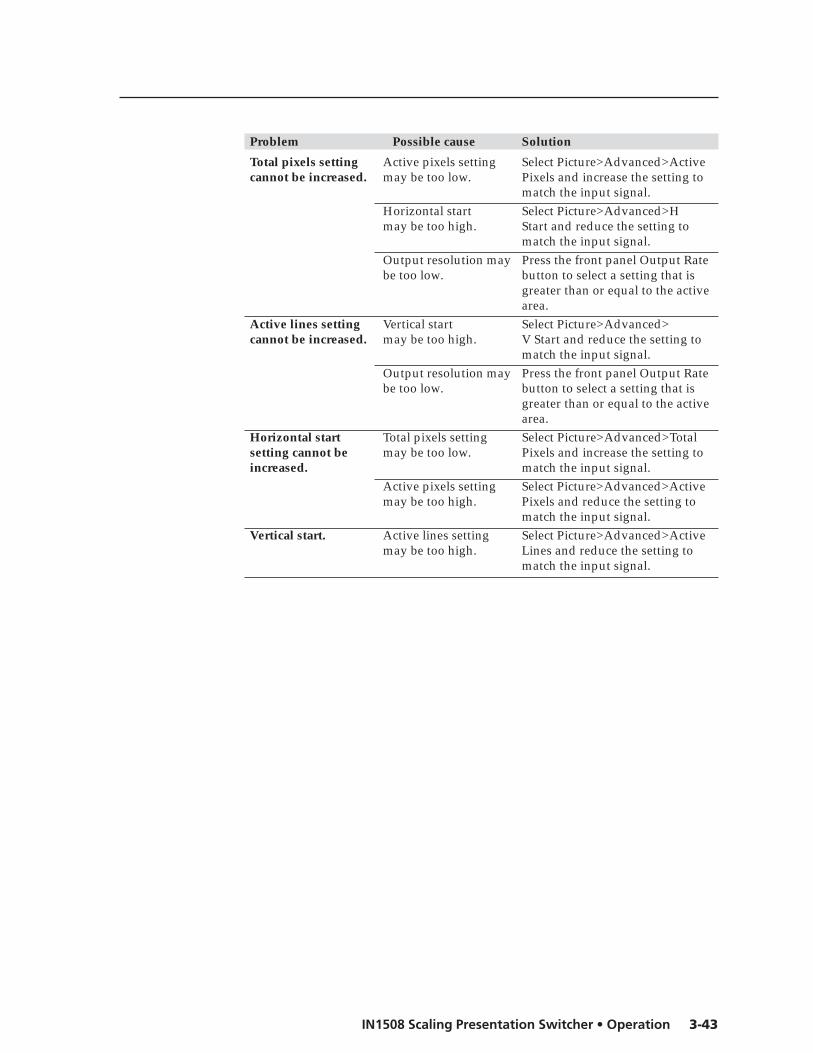
3-43IN1508 Scaling Presentation Switcher • Operation
Problem Possible cause Solution
Total pixels setting Active pixels setting Select Picture>Advanced>Activecannot be increased. may be too low. Pixels and increase the setting to
match the input signal.Horizontal start Select Picture>Advanced>Hmay be too high. Start and reduce the setting to
match the input signal.Output resolution may Press the front panel Output Ratebe too low. button to select a setting that is
greater than or equal to the activearea.
Active lines setting Vertical start Select Picture>Advanced>cannot be increased. may be too high. V Start and reduce the setting to
match the input signal.Output resolution may Press the front panel Output Ratebe too low. button to select a setting that is
greater than or equal to the activearea.
Horizontal start Total pixels setting Select Picture>Advanced>Totalsetting cannot be may be too low. Pixels and increase the setting toincreased. match the input signal.
Active pixels setting Select Picture>Advanced>Activemay be too high. Pixels and reduce the setting to
match the input signal.Vertical start. Active lines setting Select Picture>Advanced>Active
may be too high. Lines and reduce the setting tomatch the input signal.

Operation, cont’d
IN1508 Scaling Presentation Switcher • Operation3-44

IN1508 Video Scaler and Switcher
4Chapter Four
Serial Communications
Host-to-Switcher Instructions
Switcher-Initiated Messages
Switcher Error Responses
Using the Command/Response Table

IN1508 Scaling Presentation Switcher • Serial Communications4-2
Serial Communications
The switcher’s rear panel Remote 9-pin D female connector (figure 4-1) can beconnected to the RS-232 serial port output of a host device such as a computerrunning the HyperTerminal utility or a control system. This connection makessoftware control of the switcher possible.
RS-232 FunctionPin
123456789
—TXRX—
Gnd————
Not usedTransmit dataReceive dataNot usedSignal groundNot usedNot usedNot usedNot used
5 1
9 6Female
Figure 4-1 — Remote connector pin arrangement
The protocol is 9600 baud, 8-bit, 1 stop bit, no parity, and no flow control.
Host-to-Switcher InstructionsThe switcher accepts (Simple Instruction Set) SIS™ commands through theRS-232 port. SIS commands consist of one or more characters per command field.They do not require any special characters to begin or end the command charactersequence. Each switcher response to an SIS command ends with a carriage returnand a line feed (CR/LF = ), which signals the end of the response characterstring. A string is one or more characters.
Switcher-Initiated MessagesWhen a power-up occurs, the switcher responds by sending the following messageto the host:
Copyright 2005, Extron Electronics, IN1508, Version x.xx
Version x.xx is the firmware version number.
The switcher does not expect a response from the host; but, for example, the hostprogram might request a new status.
Switcher Error ResponsesWhen the switcher receives an SIS command and determines that it is valid, itperforms the command and sends a response to the host device. If the switcher isunable to perform the command because the command is invalid or containsinvalid parameters, the switcher returns an error response to the host. The errorresponse codes are:
E01 — Invalid input channel number (too large)E09 — Invalid function number (too large)E10 — Invalid commandE13 — Invalid value (out of range)E17 — Invalid command for signal type

4-3IN1508 Scaling Presentation Switcher • Serial Communications
Using the Command/Response TableThe command/response table begins on the next page. Except for the gain andattenuation settings, upper or lower case letters are acceptable in the commandfield. Command and response examples are shown throughout the table.
The table below shows the hexadecimal equivalent of each ASCII command.
ASCII to HEX Conversion TableSpace
Symbol definitionsSymbols ( Xn values), defined below, are used throughout the command/responsetable that begins on page 4-4. The symbols represent variables in the command/response table fields.
= CR/LF (carriage return/line feed) (hex 0D 0A)
= CR (no line feed)• = Space
Esc = Escape key
X1 = Input number 1 through 8
X2 = Switcher resolution:
01 = 640 x 480 (VGA) 11 = 480p02 = 800 x 600 (SVGA) 12 = 576p03 = 1024 x 768 (XGA) 13 = 720p04 = 1280 x 1024 (SXGA) 14 = 1080i05 = 1024 x 852 15 = 1080p06 = 1024 x 1024 16 = 1280 x 76807 = 1366 x 768 17 = 1440 x 90008 = 1365 x 1024 18 = 1680 x 105009 = 1400 x 1050 19 = 1280 x 80010 = 1600 x 1200 (UXGA) 20 = 852 x 480
X3 = Video refresh rate:
1 = 50 Hz 3 = 75 Hz2 = 60 Hz
X4 = On/off status (0 = off, 1 = on)
X5 = Picture adjustment range (000 through 128)
X6 = Horizontal shift range (000 through current horizontaloutput resolution)
X7 = Vertical shift range (000 through current verticaloutput resolution)
X8 = Sharpness level (00 through 128)
X9 = Horizontal start position (000 thru 200)
X10 = Vertical start position (000 thru {variable})
X11 = Pixel phase value (0 to 31)
X12 = Gain value (numeric dB value, 0 to +9)
X13 = Attenuation value (numeric dB value, -1 to -53)
X14 = Gain/attenuation (-53 dB to +9 dB, each step = 1 dB)
X15 = Output volume (0 to 100)
X16 = Detected input signal standard (input 1 through 4 or 5):
0 = none 3 = NTSC 4.43 1 = NTSC 3.58 4 = SECAM 2 = PAL
X17 = Input 5 video type:
0 = Interlaced component 2 = HDTV 1 = Progressive component
X18 = PIP size:
00 = 1/4 (default) 03 = 1/2501 = 1/9 04 = Side-by-side normal02 = 1/16 05 = Side-by-side full screen
X19 = Output video type:
0 = Y, B-Y, R-Y 2 = RGBS 1 = RGBHV 3 = RGsB
X20 = Output sync polarity:
0 = H–/V– 2 = H+/V– 1 = H–/V+ 3 = H+/V+
X21 = Aspect ratio (0 = 4:3, 1 = 16:9)
X22 = Menu buttons:
00 = Menu 03 = Left01 = Up 04 = Right02 = Down 05 = Enter
X23 = Pixel and line values (The range depends on the inputresolution applied and the output resolution selected.)
X24 = Audio follow:
0 = Follow main window 2 = Toggle audio source 1 = Follow PIP window
X25 = Window size (The range depends on the inputresolution applied and the output resolution selected.)

Serial Communications, cont’d
IN1508 Scaling Presentation Switcher • Serial Communications4-4
Command/response table for SIS commandsCommand ASCII Command Response Additional description
(host to switcher) (switcher to host)
Input selection and PIP swapSelect video and audio input X1 ! Chn X1 Select video and audio input X1 .
Example: 2! Chn02 Select video and audio input 2.View video and audio input ! Chn X1 Input X1 is selected.Swap PIP and main windows % Pch X1 X1 is the input in the PIP
window.
Audio/video breakaway switching
Audio/video breakaway switching is only available when the switcher’s PIP function is off (the frontpanel PIP On LED is unlit). The switcher responds with an E10 error if the PIP On is lit (the PIPfunction is active.
Switch audio input X1$ In X1 •Aud Select audio input X1 .Switch video input X1& In X1 •Vid Select video input X1 .
Switcher output video resolutionSet output resolution and rate X2 * X3 = Rte X2 * X3 Command character is “equals”.
Example: 5*3= Rte5*3 Set the output to 1024x852 at75Hz.
View resolution and rate = Rte X2 * X3
Video muteSet video mute on 1B Vmt X4 Set the video output to black.
Set video mute off 0B Vmt X4 Set the video output to theselected input 1 through 8.
View video mute status B Vmt X4 Video mute is X4 (on or off).
Color
Color adjustments are available only for inputs 1 through 4. If input 5 is configured as interlacedcomponent video, its color can also be adjusted. Color adjustments are made to the selected inputonly.
Set a specific color value X5 C Col X5 Specify the color adjustment.Increment color value +C Col X5 Increase the color setting by one.Decrement color value –C Col X5 Decrease the color setting by one.View the color value C Col X5 Show the color setting.
Tint
Tint adjustments are available only for inputs 1 through 4. Tint adjustments are made to theselected input only.
Set a specific tint value X5 T Tin X5 Specify the tint adjustment.Increment tint value +T Tin X5 Increase the tint setting by one.Decrement tint value –T Tin X5 Decrease the tint setting by one.View the tint value T Tin X5 Show the tint setting.
BrightnessSet a specific brightness value X5 Y Brt X5 Specify the brightness
adjustment.Increment brightness value +Y Brt X5 Increase the brightness by one.Decrement brightness value –Y Brt X5 Decrease the brightness by one.View the brightness value Y Brt X5 Show the brightness setting.

4-5IN1508 Scaling Presentation Switcher • Serial Communications
Command/response table for SIS commands (cont’d)
Command ASCII Command Response Additional description(host to switcher) (switcher to host)
ContrastSet a specific contrast value X5 ^ Con X5 Specify the contrast adjustment.Increment contrast value +^ Con X5 Increase the contrast by one.Decrement contrast value –^ Con X5 Decrease the contrast by one.View the contrast value ^ Con X5 Show the contrast setting.
Horizontal size (window)Increase the horizontal size +: Hsz X25 Widen the picture.Decrease the horizontal size –: Hsz X25 Make the picture narrower.View the window width : Hsz X25 Window width is X25 .
Vertical size (window)Increase the vertical size +; Vsz+ Make the picture taller.Decrease the vertical size –; Vsz– Make the picture shorter.View the window height : Vsz X25 Window height is X25 .
Horizontal shiftSet specific value X6 H Hph X6 Set the horizontal position to X6 .Nudge picture right (+4) +H Hph X6 Shift the picture right.Nudge picture left (–4) –H Hph X6 Shift the picture left.View position setting H Hph X6 Horizontal setting is X6 .
Vertical shiftSet specific value X7 / Vph X7 Set the vertical position to X7 .Nudge picture up (+4) +/ Vph X7 Shift the picture up.Nudge picture down (–4) –/ Vph X7 Shift the picture down.View position setting / Vph X7 Vertical setting is X7 .
Sharpness filterSet a specific detail filter level X8 D Shp X8 Set the detail level.Increment detail filter value +D Shp X8 Select the next higher detail level.Decrement detail filter value –D Shp X8 Select the next lower detail level.View the detail filter value D Shp X8 Detail level is X8 .
Horizontal startSet a horizontal start value X9 ) Hst X9 Set the horizontal location of the
first active pixel.
Example: 5) Hst5 Shift active video 5 pixels to theright from the current position.
Increment horizontal start value +) Hst X9 Shift video to the right 1 pixel.Decrement horizontal start value –) Hst X9 Shift video to the left 1 pixel.View the horizontal start value ) Hst X9 Horizontal starting point is X9 .
Vertical startSet a vertical start value X10 ( Vst X10 Set the vertical location of the
first active pixel.
Example: 2( Vst2 Shift active video down 2 linesfrom the current position.
Increment vertical start value +( Vst X10 Shift video down 1 line.Decrement vertical start value –( Vst X10 Shift video up 1 line.View the vertical start value ( Vst X10 Vertical starting point is X10 .

Serial Communications, cont’d
IN1508 Scaling Presentation Switcher • Serial Communications4-6
Command/response table for SIS commands (cont’d)
Command ASCII Command Response Additional description(host to switcher) (switcher to host)
Pixel phaseSet a pixel phase value X11 U Phs X11
Example: 6U Phs6 Use a pixel phase setting of 6.Increment pixel phase value +U Phs X11 Increase the pixel phase setting.Decrement pixel phase value –U Phs X11 Decrease the pixel phase setting.View the pixel phase value U Phs X11 Pixel phase value is X11 .
FreezeEnable freeze 1F Frz1 Output a “frozen” video image.Disable freeze 0F Frz0 Turn off freeze (output motion
video).View the freeze status F Frz X4 Show the freeze status.
Example: F Frz0 Freeze mode is off.
ZoomZoom in +{ Zom Zoom in on the video image.Zoom out –{ Zom Zoom out from the video image.
Audio gain and attenuation
The SIS commands for setting audio gain and attenuation are case sensitive. “G” sets gain and “g”sets attenuation. Increment, decrement, and view are not case sensitive.
Set gain X12 G Aud X14 Set gain for the selected input toX12 dB.
Example: 3G Aud+03 Set gain for the selected input to3 dB.
Set attenuation X13 g Aud X14 Set attenuation for the selectedinput to X13 dB.
Example: 15g Aud-15 Set attenuation for the selectedinput to -15 dB.
Increment level +G Aud X14 Increase the selected input’saudio level by +1 dB.
Decrement level -G Aud X14 Decrease the selected input’saudio level by -1 dB.
View audio level G Aud X14 View gain for the selected input.Example G Aud-03 The IN1508 reports that the
audio level for the selected inputis at -3 dB of attenuation.
Audio output volumeSet the output volume X15 V Vol X15 Set the volume for the audio
output.
Increment the output volume +V Vol X15 Increase the output’s volumelevel by 1 step.
Decrement the output volume -V Vol X15 Decrease the output’s volumelevel by 1 step.
View the output volume V Vol X15 Show the volume level.
Audio delaySet the audio delay on 1@ Ad1 Delay audio to match the delay
inherent in video scaling.Set the audio delay off 0@ Ad0View the audio delay @ Ad X4
Example: @ Ad1 Audio delay is on.

4-7IN1508 Scaling Presentation Switcher • Serial Communications
Command/response table for SIS commands (cont’d)
Command ASCII Command Response Additional description(host to switcher) (switcher to host)
Audio muteSet audio mute on 1Z Amt X4 Mute the audio output.
Set audio mute off 0Z Amt X4 Unmute the audio output.View audio mute status Z Amt X4 Audio mute is X4 (on or off).
Front panel lockEnable front panel lock 1X Exe1 Lock front panel adjustments;(lock image adjustments) adjust the image via RS-232 only.Disable front panel lock 0X Exe0 Adjustments and selections can
be made from the front panel.View the lock status X Exe X4 Show lock status.
Example: X Exe0 Front panel lock is off.
Information requestsQuery firmware version Q x.xx Show the firmware version.Request part number N 60-569-01 Show the IN1508’s part #.
Request general information I (See below) Show the IN1508’s status.Chn X1•Pch X1•Std X16 Chn is the input selected for the
main window. Pch is the inputselected for the PIP window (0when PIP mode is off). Std is theautodetected input 1 through 4(or 5) video standard.
ResetsZap all IN1508 settings Esc zXXX ZapXXX Reset all settings and
adjustments to the factorydefault and erase all presets.

Serial Communications, cont’d
IN1508 Scaling Presentation Switcher • Serial Communications4-8
Command/Response Table for Special Function SIS Commands
Command ASCII Command Response Additional description(host to switcher) (switcher to host)
Command/response table for special function SIS commandsThe syntax for setting a special function is Xn * X? # where Xn is the value or variable(such as X17 in the second example below), X? is the function number (such as“2” = “Set input 5 video format” in the second example below), and # is the executecommand. To view a function’s setting, use X? #, where X? is the function number.
PanPan right –*0# Pan Pan right on a zoomed image.Pan left +*0# Pan Pan left on a zoomed image.Pan up –*1# Pan Pan up on a zoomed image.Pan down +*1# Pan Pan down on a zoomed image.
Input 5 video typeSet input video format X17 *2# In5 X17 Specify the video format
connected to input 5.
Example: 1*2# In51 Input 5 is set to progressivevideo.
View input video format 2# In5 X17
Switch modeEnable fade mode 1*3# Fad1 Video fades to black during
switches.Disable fade mode (cut mode) 0*3# Fad0 Video cuts from one input to
another during switches.View fade mode 3# Fad X4 1 = fade, 0 = cut.
PIPSet PIP size X18 *4# Pmd X18 Set PIP window size.
Example: 2*4# Pmd2 PIP window is 1/16 screen size.View PIP size 4# Pmd X18
Set PIP mode X4 *5# Pip X4 0 = PIP off, 1 = PIP on.Example: 1*5# Pip1 PIP is on.
View PIP mode 5# Pip X4
Switcher output settingsSet output sync format X19 *6# Syn X19 0 = Y, B-Y, R-Y.
1 = RGBHV (default).2 = RGBS.3 = RGsB.
Example: 1*6# Syn1 RGBHV output.View output sync format 6# Syn X19
Set output sync polarity X20 *7# Pol X20 0 = H–/V– (default).1 = H–/V+.2 = H+/V–.3 = H+/V+.
Example: 1*7# Pol1 H–/V+ polarity.View output sync polarity 7# Pol X20
Blue screenSet blue screen (blue & sync X4 *8# Blu X4 0 = off (normal output).output only) 1 = on (blue video & sync output).
Example: 1*8# Blu1 Blue & sync output for setup.View blue mode on/off 8# Blu X4

4-9IN1508 Scaling Presentation Switcher • Serial Communications
Command/response table for special function SIS commands (cont’d)
Command ASCII Command Response Additional description(host to switcher) (switcher to host)
Input aspect ratioSet the input aspect ratio to 16:9 1*9# Asp1Set the input aspect ratio to 4:3 0*9# Asp0View the selected aspect ratio 9# Asp X21
Example: 9# Asp0 The aspect ratio is set to 4:3.
Menu buttonsPresses of the menu buttons X22 *10# Mnu X22 Emulate pushing a menu button.
Example: 3*10# Mnu3 Direct the switcher to respond asif the front panel button waspushed.
Total pixelsSet a total pixel value X23 *11# Tpx X23
Example: 1344*11# Tpx1344 Use a total pixel setting of 1344.Increment total pixel value +*11# Tpx X23 Increase the total pixel setting.Decrement total pixel value –*11# Tpx X23 Decrease the total pixel setting.View the total pixel value 11# Tpx X23
Active pixelsSet an active pixel value X23 *12# Apx X23
Example: 1024*12# Apx1024 Use an active pixel setting of1024.
Increment active pixel value +*12# Apx X23 Increase the active pixel setting.Decrement active pixel value –*12# Apx X23 Decrease the active pixel setting.View the active pixel value 12# Apx X23
Active linesSet an active line value X23 *13# Aln X23
Example: 768*13# Aln768 Use an active line setting of 768.Increment active line value +*13# Aln X23 Increase the active line setting.Decrement active line value –*13# Aln X23 Decrease the active line setting.View the active line value 13# Aln X23
Audio follow sourceSet the audio to follow X24 *14# Afp X24 Set audio to follow the main or
PIP window selection.View the audio follow setting 14# Afp X24
Example: 14# Afp1 Audio follows the PIP window.
IR receiver enableDisable IR receiver 0*65# IRD0 Disable the IR receiver (do not
allow control by the infraredremote).
Enable IR receiver 1*65# IRD1 Enable the IR receiver (allowcontrol by the infrared remote).
Read IR receiver enable 65# X4 0= disable, 1 = enable (default).

Serial Communications, cont’d
IN1508 Scaling Presentation Switcher • Serial Communications4-10
Command/response table for special function SIS commands (cont’d)
Command ASCII Command Response Additional description(host to switcher) (switcher to host)
EDID emulation (DVI input 8 only)Set EDID emulation X2 * X3 *41# DDC X2 * X3 Set the EDID to emulate a specific
resolution (default: 1024 x 768 at60 Hz).
Example: 15*2*41# DDC15*2 Set EDID emulation to 1080p at60 Hz.
Read EDID emulation 41# DDC X2 * X3
DVI auto-detect (DVI input 8 only)
When DVI auto-detect is enabled, the horizontal start and vertical start adjustments are disabled. Ifyou need to change these settings, disable DVI auto-detect.
Disable DVI auto detect 0*76# IRD80 Disable the auto adjust feature(allow the user to set horizontalstart and vertical start).
Enable DVI auto-detect 1*76# DVI81 Allow the IN1508 to auto adjust theDVI settings (default).
Read DVI auto-detect 76# DVI8 X4 0= disable, 1 = enable (default).

IN1508 Scaling Presentation Switcher
AAppendix A
Specifications and Part Numbers
Specifications
Part Numbers

IN1508 Scaling Presentation Switcher • Specifications and Part NumbersA-2
Specifications and Part Numbers
Specifications
Video inputNumber/signal type ................... 2 composite video
2 S-video1 component video (interlaced, progressive, or HDTV)2 RGBHV, RGBS, RGsB1 DVI-D digital video (single link)
Connectors ................................... 2 female BNC (composite video)2 female 4-pin mini DIN (S-video)3 female BNC (component video)2 female 15-pin HD (RGB)1 DVI female (DVI-I)
Nominal level ............................... 1 Vp-p for Y of component video and S-video, and for composite video0.7 Vp-p for RGB and for R-Y and B-Y of component video0.3 Vp-p for C of S-video
Minimum/maximum levels ....... 0 V to 1.0 Vp-p with no offsetImpedance .................................... 75 ohmsHorizontal frequency .................. 24 kHz to 100 kHzVertical frequency ....................... 50 Hz to 120 HzResolution range .......................... 640 x 480 to 1600 x 1200, 480p, 576p, 720p, 1080i, and 1080pReturn loss .................................... <-30 dB @ 5 MHzDC offset (max. allowable) ......... 0.5 V
Video processingEncoder ......................................... 9 bit digitalDecoder ......................................... 10 bit digitalDigital sampling ........................... 24 bit, 8 bits per color; 140 MHz standardColors ............................................ 16.78 million
Video outputNumber/signal type ................... Scaled RGBHV, RGBS, RGsB; Y, R-Y, B-YConnectors ................................... 1 female 15-pin HDNominal level ............................... 1 Vp-p for Y of component video
0.7 Vp-p for RGB and for R-Y and B-Y of component videoMinimum/maximum levels ....... 0 V to 2.0 Vp-pImpedance .................................... 75 ohmsVertical frequency ....................... 50 Hz, 60 Hz, or 75 Hz, depending on selected output resolutionScaled resolution .......................... 640x4801,2,3, 800x6001,2,3, 852 x 8001,2, 1024x7681,2,3, 1024x8521,2,3, 1024x10241,2,3,
1280x7682, 1280 x 8001,2, 1280x10241,2,3, 1366x7681,2,3, 1365x10241,2,3,1400x10501,2, 1440 x 9002,3, 1600x12001,2, 1680 x 10502, 480p2, 576p1, 720p1,2,1080i1,2, 1080p2
1 = at 50 Hz; 2 = at 60 Hz; 3 = at 75 HzReturn loss .................................... -21 dB @ 5 MHzDC offset ....................................... ±300 mV maximum with input at 0 offset
SyncInput type ..................................... RGBHV, RGBS, RGsBOutput type .................................. RGBHV, RGBS, RGsB; Y, R-Y, B-Y (tri-level)Standards ...................................... NTSC 3.58, NTSC 4.43, PAL, SECAMInput level ..................................... 0 V to 5 Vp-pOutput level .................................. TTL: 5.0 Vp-p, unterminatedInput impedance .......................... 75 ohmsOutput impedance ....................... 75 ohms

A-3IN1508 Scaling Presentation Switcher • Specifications and Part Numbers
Max input voltage ........................ 5V p-pPolarity .......................................... Positive or negative (switch-selectable)
AudioGain ................................................ Unbalanced output: 0 dB; balanced output: +6 dBFrequency response .................... 20 Hz to 20 kHz, ±1.1 dBTHD + Noise ................................. 0.03% @ 1 kHz at nominal level, 0 dB gain S/N ............................................... >90 dB at rated maximum outputCrosstalk ....................................... <-80 dB @ 1 kHzStereo channel separation .......... >84 dB @ 1 kHz
Audio inputNumber/signal type ................... 8 stereo, unbalancedConnectors ................................... 5 pairs of RCA (tip-ring) jacks
(3) 3.5 mm mini stereo (tip-ring-sleeve) jacksImpedance .................................... >10k ohms unbalanced, DC coupledNominal level ............................... +4 dBu (1.23 Vrms), -10 dBV (316 mVrms)Maximum level ............................ +10.4 dBu, (unbalanced) at 1% THD+NInput gain adjustment ................. -53 dBu to +9 dBu, adjustable per input
0 dBu = 0.775 Vrms, 0 dBV = 1 Vrms, 0 dBV 2 dBu.
Audio outputNumber/signal type ................... 1 stereo, unbalanced
1 stereo, balanced/unbalancedConnectors ................................... 1 pair of RCA (tip-ring) jacks
(1) 3.5 mm captive screw connector, 5 poleImpedance .................................... 50 ohms unbalanced, 100 ohms balancedGain error ..................................... ±0.1 dB channel to channelMaximum level (Hi-Z) ................ >+21 dBu, balanced at 1% THD+N
>+11 dBu, unbalanced at 1% THD+NMaximum level (600 ohm) ......... >+14 dBm, balanced at 1% THD+N
>+10 dBm, unbalanced at 1% THD+N
Control/remote — decoder/scalerSerial control port ........................ RS-232, 9-pin female D connectorBaud rate and protocol ............... 9600 baud, 8 data bits, 1 stop bit, no paritySerial control pin configurations 2 = TX, 3 = RX, 5 = GNDIR controller module ................... IN1508 RemoteProgram control .......................... Extron’s Simple Instruction Set (SIS™)
GeneralPower ............................................ 100 VAC to 240 VAC, 50/60 Hz, 30 watts, internalTemperature/humidity .............. Storage: -40 to +158 °F (-40 to +70 °C) / 10% to 90%, noncondensing
Operating: +32 to +122 °F (0 to +50 °C) / 10% to 90%, noncondensingCooling .......................................... ConvectionRack mount .................................. Yes, with included bracketsEnclosure type .............................. MetalEnclosure dimensions ................. 1.75" H x 17.5" W x 8.5" D (1U high, full rack wide)
4.4 cm H x 44.4 cm W x 21.6 cm D(Depth excludes connectors and knobs. Width excludes rack ears.)
Product weight ............................. 7.0 lbs (3.2 kg)

Specifications and Part Numbers, cont’d
IN1508 Scaling Presentation Switcher • Specifications and Part NumbersA-4
Shipping weight ........................... 10 lbs (5 kg)Vibration ....................................... ISTA 1A in carton (International Safe Transit Association)Listings .......................................... UL, CULCompliances ................................. CE, FCC Class A, VCCI, AS/NZS, ICESMTBF ............................................. 30,000 hoursWarranty ....................................... 3 years parts and labor
All nominal levels are at ±10%.Specifications are subject to change without notice.
Part Numbers
Included partsThese items are included in each order for an IN1508:
Included parts Part number
IN1508 Scaling Presentation Switcher 60-569-01IN1508 infrared remote controlRubber feet (self-adhesive) (4)MBD 149 Rack and through-desk mounting kit 70-077-03IEC power cord 27-044-01Tweeker (small screwdriver)IN1508 User’s Manual
Suggested adaptersAdapter Part number
SVHSM-BNCF S-video male to 2 BNC adapter, female, 8" 26-353-02BNC male to RCA female adapter 10-264-01HDMIF-DVIDM HDMI female to DVI-D male adapter 26-616-01HDMIM-DVIDF HDMI male to DVI-D female adapter 26-617-01
Cables
Bulk cablesCable Part number
RG6-1 bulk , 500' 22-098-02RG6 male crimp connectors, qty. 50 100-260-01MHR-2 mini high resolution 500' (150 m) 22-123-03MHR-2P Plenum mini high resolution 500' (150 m) 22-129-03BNC Mini HR crimp connectors, qty. 50 100-250-51RG59 high resolution 500' (150 m) 22-145-02RG59P Plenum high resolution 500' (150 m) 22-146-02RG59 BNC male crimp connectors, qty. 30 100-257-51
Precut cablesCable Part number
RG6-1 3' (3 feet/0.9 meters) 26-383-01SVHS cable, various lengths 26-316-xxBNC-4-25' MHR (25 feet/7.5 meters) 26-210-04BNC-5-25' MHR (25 feet/7.5 meters) 26-260-03

A-5IN1508 Scaling Presentation Switcher • Specifications and Part Numbers
High performance DVI cablesCable Part number
IN9700/6 DVI male to male 6' (1.8 meters) 26-584-06IN9700/25 DVI male to male 25' (7.6 meters) 26-584-01IN9700/35 DVI male to male 35' (10.6 meters) 26-584-02IN9700/50 DVI male to male 50' (15.2 meters) 26-584-03IN9700/75 DVI male to male 75' (22.8 meters) 26-584-04

Specifications and Part Numbers, cont’d
IN1508 Scaling Presentation Switcher • Specifications and Part NumbersA-6

Extron’s WarrantyExtron Electronics warrants this product against defects in materials and workmanship for a periodof three years from the date of purchase. In the event of malfunction during the warranty periodattributable directly to faulty workmanship and/or materials, Extron Electronics will, at its option,repair or replace said products or components, to whatever extent it shall deem necessary to restoresaid product to proper operating condition, provided that it is returned within the warranty period,with proof of purchase and description of malfunction to:
USA, Canada, South America, Europe, Africa, and the Middle East:and Central America:
Extron Electronics, EuropeExtron Electronics Beeldschermweg 6C1001 East Ball Road 3821 AH AmersfoortAnaheim, CA 92805, USA The Netherlands
Asia: Japan:
Extron Electronics, Asia Extron Electronics, Japan135 Joo Seng Road, #04-01 Kyodo BuildingPM Industrial Bldg. 16 IchibanchoSingapore 368363 Chiyoda-ku, Tokyo 102-0082
Japan
This Limited Warranty does not apply if the fault has been caused by misuse, improper handlingcare, electrical or mechanical abuse, abnormal operating conditions or non-Extron authorizedmodification to the product.
If it has been determined that the product is defective, please call Extron and ask for an ApplicationsEngineer at (714) 491-1500 (USA), 31.33.453.4040 (Europe), 65.383.4400 (Asia), or 81.3.3511.7655 (Japan)to receive an RA# (Return Authorization number). This will begin the repair process as quickly aspossible.
Units must be returned insured, with shipping charges prepaid. If not insured, you assume the riskof loss or damage during shipment. Returned units must include the serial number and adescription of the problem, as well as the name of the person to contact in case there are anyquestions.
Extron Electronics makes no further warranties either expressed or implied with respect to theproduct and its quality, performance, merchantability, or fitness for any particular use. In no eventwill Extron Electronics be liable for direct, indirect, or consequential damages resulting from anydefect in this product even if Extron Electronics has been advised of such damage.
Please note that laws vary from state to state and country to country, and that some provisions ofthis warranty may not apply to you.

Extron Electronics, USA1230 South Lewis StreetAnaheim, CA 92805800.633.9876 714.491.1500 FAX 714.491.1517
Extron Electronics, EuropeBeeldschermweg 6C3821 AH Amersfoort, The Netherlands+800.3987.6673 +31.33.453.4040FAX +31.33.453.4050
Extron Electronics, JapanKyodo Building, 16 IchibanchoChiyoda-ku, Tokyo 102-0082Japan+81.3.3511.7655 FAX +81.3.3511.7656
Extron Electronics, Asia135 Joo Seng Rd. #04-01PM Industrial Bldg., Singapore 368363+800.7339.8766 +65.6383.4400 FAX +65.6383.4664www.extron.com
© 2008 Extron Electronics. All rights reserved.