Upper Harbor Brook IRM Construction Work Plan · Joseph J. Heath, Esq., Onondaga Nation ... gOY...
55
Honeywell Honeywell 301 Plainfield Road Suite 330 Syracuse, NY 13212 ) 15·552·9700 315-552-9780 Fax September 5, 2012 To: Diane Carlton, NYSDEC, Region 7 (I PDF) Holly Sammon, Onondaga County Public Library (I bound) Samuel Sage, Atlantic States Legal Foundation (I bound) Joseph J. Heath, Esq., Onondaga Nation (cover letter only) Re: Letter of Transmilt al- Upper Harbor Brook IRM Repository Additions The documents below have been approved by the New York State Department of Environmental Conservation (NYSDEC) and are enclosed for your document holdings: • Upper Harbor Brook IRM Stormwater Pollution Prevention Plan (SWPPP) dated May 2012 • Upper Harbor Brook IRM Construction Work Plan dated August 2012 . {{(- John P. McAuliffe, P.E. Program Director, Syracuse Ene. cc: Tracy Smith - NYSDEC 1:\Honeywell.1163\49142.Uppcr-Harbor-Br\Corres\repository letter CWP & SWPPP.doc
Transcript of Upper Harbor Brook IRM Construction Work Plan · Joseph J. Heath, Esq., Onondaga Nation ... gOY...

HoneywellHoneywell
301 Plainfield Road
Suite 330
Syracuse, NY 13212
) 15·552·9700
315-552-9780 Fax
September 5, 2012
To: Diane Carlton, NYSDEC, Region 7 (I PDF)Holly Sammon, Onondaga County Public Library (I bound)Samuel Sage, Atlantic States Legal Foundation (I bound)Joseph J. Heath, Esq., Onondaga Nation (cover letter only)
Re: Letter of Transmiltal- Upper Harbor Brook IRM Repository Additions
The documents below have been approved by the New York State Department of EnvironmentalConservation (NYSDEC) and are enclosed for your document holdings:
• Upper Harbor Brook IRM Stormwater Pollution Prevention Plan (SWPPP) dated May2012
• Upper Harbor Brook IRM Construction Work Plan dated August 2012
S~~:, ~ ~v+~l(~. ~7 {{(-John P. McAuliffe, P.E.
Program Director, Syracuse
Ene.
cc: Tracy Smith - NYSDEC
1:\Honeywell.1163\49142.Uppcr-Harbor-Br\Corres\repository letter CWP & SWPPP.doc

New York State Department of Environmental ConservationDivision of .Environmcntal RcmcdiationRemedial Bureau 0, 12th Floor625 Broadway. Albany. New York 12233-7013Phone: (518) 402-9676' Fax: (518) 402-9020Wcbsite; www.dec.ny gOY
August 21, 2012
Me. John P. McAuliffe, P.E.Honeywell lotemntional, rnc.30 I Plainfield RoadSuite 330Syracuse, NY 13212
He: Upper Harbor Brook IRM Construction Work Plan
Dear Me. MeAulifle:
Joe MartensCommissioner
The New York State Department of Environmental Conservaiion (NYSDEC) hasreviewed the "Upper Harbor Bra()k JRM Stormwater Pollution Prevention Plan" (SWPPP) datedMay 2012 and the "Upper Harbor Bro()k lRM Construction Work Plan" (work plan) datedAugust 2012. Based on our review, the SWI'PP (conditioned on the August 16,2012 cotlnnentJetter being atlaehed to the SWI'PP) and work phm are approved. If you have any questions,please contact me at 518-402-9796.
Sincerely,
~/f.~
Tracy A. SmithProject Manager
ecc: J. Gregg, NYSDEC1. ShenandoahT. Joyal, Esq.O. Laeeelti, NYSDOHF. KirshnerE. Hahn, ]{egion 7
R. Nunes, USEPAJ. Heath, Esq.A. LowryC. WatermanR. Quail, NYSDEC
M. Sergott, NYSOOHD. Hesler, NYSDECT. Blum, NYSDECD. Edwards, aBOJ. Heekathorne, 0110

HoneywellHone}'\veJI
30'1 Plainfield RoadSuite 330
Syracuse. NY 13212
315-552-9700
315-552-9780 Fax
May 4, 2012
Mr. Tracy A. SmithProject ManagerNYSOEC Div. of Environmental RemediationRemedial Burean 0625 Broadway, 12th FloorAlbany, NY 12233-7016
RE: Upper Harbor Brook IRMCity of Syracuse, Onondaga County, NYOrder on Consent: Index #D7-0008-01-09
Dear Mr. Smith:
This letter presents the Upper Harbor Brook IRM Draft Construction Work Plan (CWP) and Final StormWater Pollution Prevention Plan (SWPPP). The changes requested by NYSDEC have been incorporatedinto the SWPPP. These plans have been prepared by O'Brien & Gere on behalf of HoneywellInternational Inc. \',
Should you have any questions regarding the work described in these documents, please contact DaveEdwards (315-956-6873) or Brian White (315-956-6862) at O'Brien & Gere or me at your earliestconvenience.
Sincerely,
JO~v-1. /J!&1,L«e , C£~John P. McAuliffe, P.E.Program Director, Syracuse
, .
Enc. (2 copies, 2 CDs)cc: Ms. Ellen Hahn
Ms. Tara BlumMr. Steven BatesMr. Geoffrey LaccettiMr. Robert NunesMargaret A. Sheen, Esq.Argie Cirillo,Esq.Mr. David CoburnBrian D. Israel, Esq.Mr. Michael SperaMr. William HagueMr. Michael SavageJoseph J. Heath, Esq.Thane Joyal, Esq.
NYSDEC Region 7 (1 copy, I CO)NYSDEC Region 7 (1 copy, 1 CO)NYSDOH (I copy, I CD)NYSDOH (ec or ec Itr only)USEPA (2 copies, 1 ec or CD)NYSDEC, Region 7 (Itr only)USEPA (Itr only)O.C. Office of the Environment (I copy, I CO)Arnold & Porter (ec or CO)AECOM (I copy,2CDs)Honeywell (ec or CD)Honeywell (ec or CD)Onondaga Nation (ec Itr only)Onondaga Nation (ec or CD)
1:\Honeywell.1163\46096.W~$tebed·B·Harb\ Docs\Col1structlon\Do<uments\Work PI~n5\CWP\Flnal S·4-12\CWP and SWPPP Submltlill Letter.doc

Mr. Tracy A. SmithMay 4, 2012Page 2
Mr. Fred KirschnerMs. Jeanne ShenandoahMs. Heidi KuhlMr. Curtis WatermanMs. Alma LowryMs. Megan MillerMr. James R. HeckathomeMr. Christopher CalkinsMr. Brian White
AESE, Inc. (ec or CD)Onondaga Nation (I copy and ec Itr only)'Onondaga Nation (I copy)Onondaga Nation <ec or CD)Onondaga Nation <ec Itr onlyParsons <ec or CD)O'Brien & Gere (ec or ec Itr only)O'Brien &Gere (ec or ec Itr only)O'Brien &Gere (cc or ec Itr only)
",,
HoneywellHoneywell
301 Plainfield Road
Suite 330
Syracuse, NY 13212
315·552·9700
315-552-9780 Fax
August 16, 2012
Mr. Tracy SmithProject ManagerNYSDEC - Division of Environmental RemediationRemedial Bureau D, 121h Floor625 BroadwayAlbany, NY 12233-7013
RE: Upper Harbor Brook IRMCity of Syracuse, Onondaga County, NYOrder on Consent: Index #D7-0008-01-09
Dear Mr. Smith:
Enclosed are the final Construction Work Plan and Health & Safety Plan in accordance with theNYSDEC's comments and O'Brien & Gere responses. The NYSDEC approved these documents fordistribution on August IS, 2012.
I. NYSDEC Comment: Page 6, Section 3.1. The HASP needs to be submitted for review.Response 1: The HASP has been previously submitted and comments addressed. Revisedversion is accompanying these responses.
2. NYSDEC Comment: Page 10, Paragraph 2, Sentence 4, Section 4.1. The sentence states that,"Existing trees with conservation value will be preserved by marking and, if possible, usingconstruction fence to identifY its location." Please include criteria for retaining trees and consult withDEC prior to the removal of large trees. In addition, a figure that identifies the locations of treeswhich were removed along with the appropriate justification for removal should be provided in theUpper Harbor Brook IRM Final Engineering Report.Response 2: Native species greater than 12 inches to 18 inches in diameter at chest height willbe evaluated for conservation. Prior to any removal activities, the NYS DEC will be notified ofplanned action in sufficient time to review.
3. NYSDEC Comment: Page 12, Paragraph 1, Section 5. [t is stated that " ...during non-work hours orperiods of heavy precipitation which result in flows in excess of average, water will flood some ofthe work zones." To minimize contaminated water migrating off-site or the generation ofconstruction water (from pumping out flooded areas) pumps will likely need to be run during nonwork hours. Please revise as necessary.Response 3: The comment is noted. Existing pumps associated with Upper Harbor Brook bypass operations will be operational during non-working hours to maintain work areas in a dryenvironment. Each work area will be completed as soon as practical to minimize open areas.
4. NYSDEC Comment: Page IS, Section 5, Paragraph P, last sentence and page 29, Paragraph 2,Section 8. The text describes the dewatering process of sediments within a confined sediment basin.
1:\Hol1eywell 1163\49142.Upper.Harbor-Br\Corres\Correspondence _ Agency\NVSDEC TSmilh • CWP for Final Approval.doc

Mr. Tracy A. SmithAugust 16, 2012Page 2
The disposal process of the contaminated water from dewatering should be indicated here. Further,please include the location of the confined sediment basin on Figure I and include a discussion of thebasin within the work plan.Response 4: The comment is noted. Additional text describing the removal and disposal of thewater generated by the dewatering of contained sediments has been added to both sectionsreferenced. The Water Management Plan (Fig 1) has 4 staging areas which are located in areaswhere material storage may be required. These are the locations where confined basins wouldbe constructed if required.
5. NYSDEC Comment: Page 16, Section 6. This section should refer to a wetlands restoration andwetlands maintenance and monitoring plans.Response 5: The wetlands restoration plan will comply with Appendix L of the approvedDesign Report. A Maintenance and Monitoring plan is in preparation and will be forthcoming.
6. NYSDEC Comment: Page 16, paragraph 3, Section 6. Please indicate here that only native plantswill be chipped and used as wetland cover; non-native or invasive species will not be used, asindicated on Sheet G-l, Wetland Restoration Notes, #11.Response 6: Text revised as requested.
7. NYSDEC Comment: Page 16, paragraph 6, Section 6. The organic content of the topsoil listed, 620%, should be consistent with organic content listed (4-20%) in the Wetland Restoration Notes(note #2), Figure G-I. Please revise accordingly.Response 7: Text revised as requested.
8. NYSDEC Comment: Page 19, Section 7. Throughout this section, reference is made to backfill with"Type J" material; however the appropriate backfill for wetland areas is "Type L" material. Pleaseclarify.Response 8: Comment is noted. Section 6 refers to the wetland excavation and restorationefforts and Type "L" is identified as the material to use. Type "J" material will be ntilized asbackfill for the Open Water Areas and specific ditches. Sennet Bank Run will be used asbackfill in DIE ditch and Railroad Ditches 1 & 2 as identified in the contract drawiugs.
9 NYSDEC Comment: Page 19, Paragraph 3h "Open Water Area -4", Section 7 and page 20,Paragraph 5e "Open Water Area -3", Section 7. The last sentence indicates that the "soil exhibitingstaining and odor will be segregated and tested." The text should refer to Section 11.1 "Excavationand Transport of Materials from Upper Harbor Brook" for specific analyses. Please reviseaccordingly.Response 9: Comment is noted and text revised..
10 NYSDEC Comment: Page 21, paragraph 7e "Open Water Area -2", Section 7 and page 21, Paragraphge "Open Water Area -1". Please indicate why excavated soil from these areas will not undergolaboratory analysis (similar to other open water areas).Response 10: Comment is noted and revised in text.
II NYSDEC Comment: Page 22, Paragraph 1, Section 7.B. In the fourth sentence it states that cleaningand inspection of the storm sewer pipe will be discussed in Section 10, but it is not included here.Please include this section and revise.Response 11: Comment is noted and text added to Section 7.

Mr. Tracy A. SmithAugust 16, 2012Page 3
12 NYSDEC Comment: Page 22 and 23. In item number 6 of Section 7.B is it necessary to transfer thematerial from smaller trucks into the larger truck? Due to the location of the 1-690 drainage ditch thematerial can be directly placed on Wastebed B if appropriate. Please revise as necessary.Response 12: The 1-690 ditch will require off road trausporters in certain areas along the ditchas wet conditions and steep grades exist which do not permit the use of conventional dumptrucks. Other locations within the project a..ea will also utilize direct load and douhle handlingdepending upon the circumstance.
13 Page 33, Section ILL Please see my May 24, 2012 email (attached) to Tom Conklin regarding theWastebed B soil piles. This section will need to be consistent with the email and any additionaldiscussions regarding the disposal of material.Response 13: Comment is noted. Refe..enced section has been ..evised to reflect theafo..ementioned email to Tom Conklin.
14 Page 35, Paragr.aph I, Section 12. It is stated here that discrete soil samples will be collected from 26locations following excavation for informational purposes only. Please indicate the value of usingdiscrete rather than composite samples for post-excavation sampling.Response 14: Discrete samples are proposed ..ather than composite samples during this wo..kdue to the need to backfill excavations immediately based upon the p..oposed constructionmethods and railroad requirements. We feel that the uumbe.. of disc..ete samples (26) issufficient to document the materials that will be left in place as part of this ..emedial work.
15 Appendix B, page I, Paragraph I, Bullets 3 and 6. The text refers to the installation of an HDPE linerin the Wastebed DIE ditch and in OW-4/Culvert 4; however, it should refer to an LLDPE liner asspecified on Sheets 0-37 and 0-38. Please revise accordingly.Response 15: Comment is noted aud cor..ection made to the text.
16 Appendix B, page I, Paragraph I, Bullets I, 5, and 7. The text should note that a LLDPE liner will beinstalled in the 1-690 Ditch, OW-I, OW-2, and OW-3. Please revise.Response 16: Commeut is noted and co....ection made to the text.
17 Appendix B, page I, Introduction. The text states, "Perimeter air monitoring will evaluate potentialair quality impacts on the surrounding community from volatile organic compounds (VOCs), dust,and odors." It is suggested that the text be revised to read, "Perimeter air monitoring will evaluatepotential air quality impacts from remedial activities at the site from volatile organic compounds(VOCs), dust, and odors." As written, the text suggests that the surrounding community will beimpacted.Response 17: Text will be revised to ..ead: "Perimete.. air monitoring will evaluate potentialai.. quality impacts f..om ..emedial activities at the site f..om volatile organic compounds(VOCs), dust, and odo..s."
18 Appendix B, page 2, Community Receptors, Monitoring Locations. The last paragraph on page Isuggests that physical locations of air monitors will be moved daily. Is this correct? Or does thismean that stationary monitors will be deployed and only specific monitors will be used on a dailybasis? Please clarify.Respouse 18: That is correct, the mouito.. locations will be moved on a daily basis dependingupou the p..edicted wind direction each day. The text will be edited to clarify.

Mr. Tracy A. SmithAugust 16,2012Page 4
19 Appendix B, page 2, Dust Monitoring. When more than one downgradient monitor is needed due tomultiple work areas, will additional up gradient monitors also be deployed? Please clarifY.Response 19: One upwind dust monitor will generally be used to determine ambientbackground dust for all downwind monitors. CAMP text will be edited to clarify.
20 Appendix B, page 2, Dust Monitoring. Control Level and Work Perimeter Limit. Please provide areference for the use of! 00 ug/m3 and 150 ug/m3 as benchmark levels (especially in light of differentlevels used at other sites). While the difference in the levels may not be significant, it would behelpful to understand why the criteria at one site may be different than what is being used at another.Response 20: 100 and 150 /1g.m3 levels are used as recommended in NYSDOH GenericCommunity Air Monitoring Program (gCAMP) Guidance and are the standard levels used forcommunity air monitoring when specific project conditions or discussions with regulatoryagencies do not lead to site-specific levels.
21 Appendix B, page 2, VOC Monitoring. When more than one downgradient monitor is needed due tomultiple work areas, will additional up gradient monitors also be deployed? Please clarifY.Response 21: One npwind TVOC monitor will be used to determine ambient backgroundTVOCs for all downwind monitors. CAMP text will be edited to clarify.
22 Appendix B, page 3, Investigation Level, Control Level, and Work Perimeter Limit. Please provide areference for the use of 2 ug/mJ
, 3 ug/mJ, and 5 ug/mJ
. Specifically, the difference between siterelated activities generation concentrations of 2 ug/m3 and 3 ug/mJ seems difficult to reliablymeasure.Response 22: The work perimeter limit for TVOC of 5 ppm above background is the limitspecified in NYSDOH Generic Community Air Monitoring Program (gCAMP) Guidance totemporarily halt work. The lower two limits application of controls (3 ppm), and investigatethe source (2 ppm), are implemented as lower preventive levels to reduce the frequency ofconditions requiring work stoppage. The TVOC levels are consistent with other perimeter airmonitoring programs conducted for the Honeywell Portfolio. Investigation to determine whichsite activities are cansing perimeter concentrations at 2 ppm or above may also include use ofTVOC monitors utilized for work zone monitoring.
23 Stormwater Pollution Prevention Plan, Page 02570-3, Section 02570-3.02, "Stabilization". Pleaseindicate that invasive plants shall not exceed greater than 10% cover.Response 23: Comment is noted. The "Response to Comments" letter will be included in thecopy of the SWPPP that is kept on-site during construction so that site personnel are aware ofthe modification. In addition, this letter will be included with pnblic copies of the SWPPP. Nomodification will be made to the SWPPP document.
Please contact Dave Edwards at O'Brien & Gere (315-200-7659) or me should you have any questionsregarding the information presented herein.
Sincerely,
JD~" I Nlt~(~John P. McAuliffe, P.E. 117 caProgram Director, Syracuse

Mr. Tracy A. SmithAugust 16, 2012Page 5
Ene. (2 copies, 2 CDs)
cc: Ms. Ellen HahnMs. Tara BlumMr. Steven BatesMr. Geoffrey LaccettiMr. Robert NunesMargaret A. Sheen, Esq.Argie Cirillo,Esq.Mr. David CoburnBrian D. Israel, Esq.Mr. Michael SperaMr. William HagueMr. Michael SavageJoseph J. Heath, Esq.Thane Joyal, Esq.Mr. Fred KirschnerMs. Jeanne ShenandoahMr. Curtis WatermanMs. Alma LowryMs. Megan MillerMr. James R. HeckathorneMr. Christopher CalkinsMr. Brian White
NYSDEC Region 7 (1 copy, I CD)NYSDEC Region 7 (1 copy, 1 CD)NYSDOH (1 copy, 1 CD)NYSDOH (ec or ec Itr only)USEPA (2 copies, 1 ec or CD)NYSDEC, Region 7 (Itr only)USEPA (ltr only)O.c. Office of the Environment (1 copy, I CD)Arnold & Porter (ec or CD)AECOM (1 copY,2CDs)Honeywell (ec or CD)Honeywell (ec or CD)Onondaga Nation (ec Itr only)Onondaga Nation (ec or CD)AESE, Inc. (ec or CD)Onondaga Nation (I copy and ec Itr only)Onondaga Nation (ec or CD)Onondaga Nation (ec Itr onlyParsons (ec or CD)O'Brien & Gere (ec or ec Itr only)O'Brien &Gere (ec or ec Itr only)O'Brien &Gere (ec or ec Itr only)
August 16, 2012
Upper Harbor Brook Interim Remedial Measure
Geddes, New York
CONSTRUCTION WORK PLAN
Honeywell

UPPER HARBOR BROOK IRM│CONSTRUCTION WORK PLAN
1 | Final: August 16, 2012
I:\Honeywell.1163\49142.Upper-Harbor-Br\Docs\Work Plans\CWP\Final to DEC\CWP UHB DEC Response_Final __8-15-12.doc
TABLE OF CONTENTS
1 Introduction ....................................................................................................................................................................................... 3 1.1 Project Background ................................................................................................................................................................ 3 1.2 Document Organization ....................................................................................................................................................... 4
2 Project Management Staffing ..................................................................................................................................................... 5 2.1 Project Management Staff ................................................................................................................................................... 5
3 Health and Safety, Air Quality Monitoring and General Conditions .......................................................................... 6 3.1 Health and Safety .................................................................................................................................................................... 6 3.2 Air Quality monitoring .......................................................................................................................................................... 7
3.2.1 Community Air Monitoring Plan ............................................................................................................................. 7 3.3 General Conditions ................................................................................................................................................................. 7
3.3.1 Mobilization ..................................................................................................................................................................... 7 3.3.2 Site Security ..................................................................................................................................................................... 8 3.3.3 Access Roads ................................................................................................................................................................... 8 3.3.4 Staging Areas ................................................................................................................................................................... 9 3.3.5 Decontamination Areas .............................................................................................................................................. 9
4 Erosion and Sediment Control ................................................................................................................................................ 10 4.1 Resource Protection............................................................................................................................................................ 10 4.3 Runoff and Drainage Control .......................................................................................................................................... 10 4.4 Erosion and Sediment Control ....................................................................................................................................... 10 4.5 Maintenance and Inspection .......................................................................................................................................... 11
5 Water Management ..................................................................................................................................................................... 12 6 Excavation - Wetlands ................................................................................................................................................................ 16 7 Excavation – Upper Harbor Brook/Tributaries .............................................................................................................. 18 8 Pump Station Construction ...................................................................................................................................................... 30 9 Startup and Commissioning ..................................................................................................................................................... 32
9.1 Commissioning Plan ........................................................................................................................................................... 32 9.1.1 Installation Commissioning (IC) Protocol ....................................................................................................... 32 9.1.2 Operation Commissioning (OC) Protocol......................................................................................................... 32
9.2 System Turnover Package ................................................................................................................................................ 32 10 Construction Quality Assurance ........................................................................................................................................ 33 11 Material Handling and Disposal Plan ............................................................................................................................... 34
11.1 Excavation and Transport of Materials from Upper Harbor Brook ...................................................... 34 11.2 Well Installation .......................................................................................................................................................... 35
12 Documentation Sampling ..................................................................................................................................................... 36

UPPER HARBOR BROOK IRM│CONSTRUCTION WORK PLAN
2 | Final: August 16, 2012
I:\Honeywell.1163\49142.Upper-Harbor-Br\Docs\Work Plans\CWP\Final to DEC\CWP UHB DEC Response_Final __8-15-12.doc
APPENDICES A. Schedule
B. CAMP
C. Water Management Plan
D. Traffic/Haul Routes
E. Design Drawings
F. Documentation Sampling Locations

UPPER HARBOR BROOK IRM│CONSTRUCTION WORK PLAN
3 | Final: August 16, 2012
I:\Honeywell.1163\49142.Upper-Harbor-Br\Docs\Work Plans\CWP\Final to DEC\CWP UHB DEC Response_Final __8-15-12.doc
1 INTRODUCTION
This Construction Work Plan summarizes O’Brien & Gere’s proposed approach to the construction, and start-up/commissioning of the Upper Harbor Brook Interim Remedial Measure (IRM) in Geddes, New York. The Upper Harbor Brook IRM is a component of the Wastebed B/Harbor Brook Site IRM, which also includes the East and West barrier walls and associated groundwater collection systems, and the area between the East and West barrier walls and the Onondaga Lake shoreline, referred to as the Outboard Area, and lower Harbor Brook.
The purpose of this Construction Work Plan is to provide specific project information including the project approach, project management and organization, project deliverables, schedule, and assumptions.
1.1 PROJECT BACKGROUND
A Preliminary Site Assessment (PSA) was performed at the Site in the summer of 2000 and winter of 2001 in accordance with the requirements of Consent Order D-7-0001-00-02 between the NYSDEC and Honeywell dated April 10, 2000 (NYSDEC, 2000). The PSA field work was performed July 2000 through May 2001 in accordance with the NYSDEC-approved PSA Work Plan (O’Brien & Gere, 2000). A summary of the analytical data collected during the PSA was submitted to the NYSDEC in September 2001 (O’Brien & Gere, 2001). Based on review of the data, and in consideration of other previous study data, the NYSDEC determined that a Remedial Investigation/Feasibility Study (RI/FS) should be implemented at the Site. The determination was communicated to Honeywell in a letter dated November 28, 2001.
The RI/FS Work Plan was submitted in September 2002 and approved on November 8, 2002 by the NYSDEC. The RI was performed in accordance with the NYSDEC-approved RI/FS Work Plan (O’Brien & Gere, 2002). The RI was also performed in accordance with the Guidance for Conducting Remedial Investigations and Feasibility Studies Under CERCLA (USEPA, 1988) and Part 300.68 of the National Contingency Plan, CERCLA as amended by the Superfund Amendments and Reauthorization Act (SARA) of 1986.
The initial RI field program was performed November 2002 through May 2004. The NYSDEC requested that additional field work be completed for the RI. The Supplemental RI was performed in accordance with the September 15, 2006 NYSDEC-approved letter work plan. The Supplemental RI field program was performed between November 2006 and June 2007. The RI Report was submitted to the NYSDEC on August 2, 2004, and a revised RI Report was submitted to the NYSDEC in November 2007 (O’Brien & Gere, 2007).
Upper Harbor Brook consists of areas upstream from Culvert #1 (North of I-690 bridge) to Open Water Area #5 (OW #5) immediately downstream of the Onondaga County floatables removal facility , as well as the manmade drainage channels and associated wetlands in this reach of Harbor Brook. These areas have been impacted by, VOC’s, metals and SVOC’s, and non-aqueous phase liquids (NAPLs) have also been observed.
The Upper Harbor Brook IRM Project consists primarily of the installation of a shallow ground water collection and conveyance system that will mitigate the discharge of impacted ground water to Upper Harbor Brook. As part of the remedy, impacted sediments will be removed from the existing ditches, wetlands, and Upper Harbor Brook. The removed sediment will be replaced with suitable substrate to facilitate habitat establishment within the affected areas. In selected areas, a membrane liner will be installed beneath the new substrate as a means of minimizing the discharge of ground water. Other elements of the IRM include wetland enhancement by planting appropriate wetland vegetation, culvert inspection, installation of a CIPP lining in the western portion of the 72- inch culvert #3 and I-690 storm sewer cleaning, and inspection.
Collected groundwater will be pumped from the two (2) pump stations constructed adjacent to the brook via force main installed as part of project, which will be connected to the East barrier wall force main, to Lakeshore Groundwater Pump Station and ultimately the Willis/Semet Groundwater Treatment Plant.

UPPER HARBOR BROOK IRM│CONSTRUCTION WORK PLAN
4 | Final: August 16, 2012
I:\Honeywell.1163\49142.Upper-Harbor-Br\Docs\Work Plans\CWP\Final to DEC\CWP UHB DEC Response_Final __8-15-12.doc
1.2 DOCUMENT ORGANIZATION
The remaining sections of this Construction Work Plan are organized as follows:
Section 2 – Project Management Staffing
Section 3 – Health and Safety, Air Quality Monitoring and General Conditions
Section 4 – Erosion and Sediment Control
Section 5 – Water Management
Section 6 – Excavation – Wetlands
Section 7 – Excavation – Upper Harbor Brook/Tributaries
Section 8 – Pump Station Construction
Section 9 – Start-up and Commissioning
Section 10 – Construction Quality Assurance
Section 11 – Material Handling and Disposal Plan
Section 12 – Documentation Sampling

UPPER HARBOR BROOK IRM│CONSTRUCTION WORK PLAN
5 | Final: August 16, 2012
I:\Honeywell.1163\49142.Upper-Harbor-Br\Docs\Work Plans\CWP\Final to DEC\CWP UHB DEC Response_Final __8-15-12.doc
2 PROJECT MANAGEMENT STAFFING
Assignments and responsibilities of the project team are summarized in the descriptions below:
2.1 PROJECT MANAGEMENT STAFF
NYSDEC PROJECT MANAGER – TRACY A. SMITH/DONALD HESLER
HONEYWELL DESIGN / CONSTRUCTION MANAGER – MICHAEL SAVAGE.
PROJECT OFFICER – BRIAN WHITE, P.E.
The role of the Project Officer is to see that Honeywell’s expectations for project quality, safety, schedule, and performance are met or exceeded. In addition, the Project Officer will periodically attend construction review meetings, and will be available on an as-needed basis to the project team.
PROJECT MANAGER – DAVID A. EDWARDS, P.E.
The Project Manager will manage the procurement and construction phases of the project on a day-to-day basis, monitor and evaluate project controls throughout all phases of the project, and see that the technical and quality objectives established during the design phase of the project are realized in the construction project. The Project Manger will serve as the primary contact between the Honeywell Project Manager and O’Brien & Gere.
CONSTRUCTION SUPERVISOR – GARY ELLINGWORTH
The primary responsibilities of the Construction Supervisor will be to manage the daily construction tasks conducted by subcontractors and direct hire crews. He will be required to control production levels according to the schedule, ensure site administration is correct and available, implement the site safety plan on a daily basis in conjunction with the Health and Safety Manager and maintain overall site efficiency.
HEALTH AND SAFETY MANAGER – STEVEN THOMPSON
The primary responsibilities of the Health and Safety Manager will be to develop, implement and enforce the Site Specific Health and Safety Plan for the project.

UPPER HARBOR BROOK IRM│CONSTRUCTION WORK PLAN
6 | Final: August 16, 2012
I:\Honeywell.1163\49142.Upper-Harbor-Br\Docs\Work Plans\CWP\Final to DEC\CWP UHB DEC Response_Final __8-15-12.doc
3 HEALTH AND SAFETY, AIR QUALITY MONITORING AND GENERAL CONDITIONS
This section summarizes O’Brien & Gere’s proposed approach to health and safety, air quality monitoring and general conditions.
3.1 HEALTH AND SAFETY
As with all O’Brien & Gere projects, safety will be a top priority. Health and safety excellence is a core value of both Honeywell and O’Brien & Gere. O’Brien & Gere believes that all injuries and occupational illnesses, as well as safety and environmental incidents are preventable. We will adhere to high standards for the safe operation of this project and the protection of the environment, employees and the people in the community. There cannot be any compromise with the safety and health of our employees, visitors, subcontractors, and any other persons who may come under our supervision.
O’Brien & Gere believes that with effective employee involvement, training, project planning and auditing that all accidents are preventable. Training and planning tools, which will be utilized and implemented by O’Brien & Gere safety staff will include the following:
O’Brien & Gere will develop a project specific Health & Safety Plan (HASP), that utilizes the existing Honeywell approved Health & Safety Plan and will incorporate specific job safety analyses (JSA), for the scope of work associated with this project. The HASP will be reviewed as part of the site orientation training and all direct hire personnel/subcontractors will be required to follow the requirements of the HASP. This HASP will be in accordance with Honeywell’s Syracuse Portfolio Health and Safety Program (HSP2). The JSA’s specifically identified for this project are as follows:
Project Health and Safety Plan:
1 Activities adjacent to the railroad (CSX Training Certification required)
2 Excavation/Trenching
3 Working near or on water
4 Installation of Sheet Pile
5 Traffic Control
6 Clearing of trees, brush
7 Fuel Storage
Each potential subcontractor who will be working for O’Brien & Gere on this project will be required to submit a completed Honeywell Safety Questionnaire Form for approval by O’Brien & Gere and Honeywell prior to initiating work onsite. O’Brien & Gere holds subcontractors to the same safety standards to which O’Brien & Gere is held accountable.
Subcontractor Safety Pre-Qualifications:
O’Brien & Gere believes in a drug and alcohol free workplace. Drug and alcohol testing is a condition for work on Honeywell projects covered by the HSP2. All employees will participate in a pre-project drug screening prior to beginning work on the project. In addition, all employees will be subject to a monthly random testing program.
Drug and Alcohol Testing:
A pre-work Health and Safety kickoff meeting will be scheduled with the project team.
Pre-Work Health and Safety Kickoff Meeting

UPPER HARBOR BROOK IRM│CONSTRUCTION WORK PLAN
7 | Final: August 16, 2012
I:\Honeywell.1163\49142.Upper-Harbor-Br\Docs\Work Plans\CWP\Final to DEC\CWP UHB DEC Response_Final __8-15-12.doc
Personnel working on this project will be required to attend a site orientation training session administered by an O’Brien & Gere’s safety supervisor prior to engaging in any work activities and/or entering the work zone.
Site Orientation Training:
Daily safety talks are documented utilizing a Daily Pre-Task Planner form found in the Honeywell Syracuse Portfolio Health and Safety Program HSP2 Document. Pre-Task Planners are prepared on a daily basis and will be reviewed with the work crew focusing on any changes in equipment, tools, work methods or site conditions as well as key hazards and safety controls.
Daily Pre-Task Planners and Weekly Toolbox Safety Meetings:
Project personnel must attend a project Weekly Toolbox Safety Meeting. These meetings are an opportunity to conduct field safety training, distribute key safety information, re-enforce safety as a priority and/or review recent inspection results directly to all project personnel.
The O’Brien & Gere safety supervisor and CM team will conduct monthly site audits to ensure compliance with the project specific HASP as well as the Honeywell’s Syracuse Portfolio Health and Safety Program.
Health and Safety Audits:
O’Brien & Gere understands the chemical and physical properties of site contaminants. Based on previous experiences with intrusive work at this particular site, we plan to perform work in modified level D protection. The actual level of protection used will be based on results of our air monitoring program.
Should conditions warrant, a three-zone approach will be used during site operations in order to contain the potential spread of contamination and control the flow of personnel, vehicles, and materials into and out of the work area. The zones include the exclusion zone, the contaminate reduction zone, and the support zone. The exclusion and contaminate reduction zones will be designated using temporary construction fence or hazard tape and be established for all intrusive work. Access to these zones will be limited to authorized individuals.
3.2 AIR QUALITY MONITORING
O’Brien & Gere will implement an employee work zone air monitoring program. This program will be detailed in the site specific health and safety plan.
3.2.1 Community Air Monitoring Plan The objective of the community air monitoring plan (CAMP) is to describe air monitoring during ground intrusive remedial construction activities during the ditch collection trench phase of the project. Air monitoring will evaluate potential air quality impacts on the surrounding community by real-time perimeter air monitoring for particulate (dust) and total volatile organic compounds (TVOCs). Odors will also be evaluated. The CAMP is provided as Appendix B.
3.3 GENERAL CONDITIONS
O’Brien & Gere will provide labor, equipment and coordination necessary to perform the following general work associated with the project.
3.3.1 Mobilization O’Brien & Gere will mobilize equipment, personnel, materials and supplies as necessary to perform the proposed work. Additional equipment will be mobilized as needed.
We anticipate the mobilization to include the following:
» Temporary Site Staff and Crew Trailers
» Connect electrical supply to all trailers
» Portable toilets

UPPER HARBOR BROOK IRM│CONSTRUCTION WORK PLAN
8 | Final: August 16, 2012
I:\Honeywell.1163\49142.Upper-Harbor-Br\Docs\Work Plans\CWP\Final to DEC\CWP UHB DEC Response_Final __8-15-12.doc
» Storage containers
» Temporary security fencing
» Excavators
» Skidsteers
» Side mounted brush cutters
» Dump Trucks
» Low Ground Pressure Transporters
» Frac Tanks
» 12- inch diesel bypass pumps
» 4- inch diesel bypass pumps
» 2 or 3 inch trash pumps
» Aqua Barriers and Supersacks (Water management)
» Air Monitoring Equipment
» Erosion Control materials
» Safety and Personal Protective Equipment, and
» Miscellaneous Hand Tools and Portable Equipment
3.3.2 Site Security The Construction Supervisor will be responsible for site security during working hours. On site personnel and visitors will be required to sign-in and sign-out at the O’Brien & Gere field office trailer (proposed to be located at State Fair Boulevard across from Butler Fence Company). Vehicular traffic will be permitted in designated parking areas. During non-working hours, portable equipment will be secured in on-site storage trailers located near active work areas. Excavations will be protected using construction fence and by staging equipment to minimize access. Material storage areas will have temporary cyclone fence surrounding the area with double gate entrances which are padlocked.
3.3.3 Access Roads Access throughout the Upper Harbor Brook project is a compilation of footpaths, some gravel roads and hard packed dirt pathways. In order to access several areas, additional paths will require construction. In these areas, as identified on the Traffic/Haul Routes Plan as provided in Appendix D, clearing and road construction will be necessary. This will include construction of two (2) railroad crossings of the Susquehanna line.
The method of access road construction will be as follows:
A. Clearing of a minimum area 15 feet wide. B. Flush cut all vegetation at ground level to eliminate grubbing of the area. C. Install a layer of Mirafi 600x, or equivalent, for the entire width and length of the cleared roadway. D. Install 24 inches (or as otherwise determined by the Engineer) of Type F ( or approved equal) select fill with
a minimum 10 foot wide road top. E. Crown the road surface for drainage
The access road details can be located on Sheet G-34 of the Design Drawings. Constructed access pathways will be removed in selected areas upon completion of the project. Specific pathways will remain to permit access to permanent structures such as Pump Stations 1 and 2, and to allow maintenance activities as required for the collection trenches.
UPPER HARBOR BROOK IRM│CONSTRUCTION WORK PLAN
9 | Final: August 16, 2012
I:\Honeywell.1163\49142.Upper-Harbor-Br\Docs\Work Plans\CWP\Final to DEC\CWP UHB DEC Response_Final __8-15-12.doc
3.3.4 Staging Areas A series of four (4) staging areas are currently planned for and identified on the Traffic/Haul Routes Plan as provided in Appendix D. The locations near the Floatable Control Facility and between Wastebed D/E ditch and I-690 embankment have been chosen for their proximity to public roads from which imported fill and materials can be easily delivered. Remaining staging areas are located for ease of access to work areas. Excavated material from CSX property will be removed by end of the day that it is excavated. These areas also serve as daily material staging for centralized loading areas for removal to Wastebed B.
The staging area construction process will follow these steps:
A. Clear area of vegetation. Areas chosen have minimal clearing required. Size of each area is location specific based on anticipated material storage requirements and/or daily excavation quantities.
B. Flush cut vegetation at ground level to eliminate grubbing of the area. C. Install temporary security fencing around perimeter of area. D. Install 12 oz non-woven geotextile as liner cushion E. Install 20 mil liner. F. Install 6 inches of Type “E” material. G. Install 20 mil liner H. Install hay bales around perimeter of the staging areas, which will receive excavated material, and wrap
liner material over them. Secure with sand bags on outside of hay bale barrier.
3.3.5 Decontamination Areas Decontamination pads will be constructed at exits of site to Hiawatha Blvd and State Fair Boulevard. These two (2) exits will be required to transport excavated material to Wastebed “B” via public roads. Weather dependency will determine the type of decontamination effort required. In dry weather conditions, a brush down of the tires, side panels and tailgate after travelling over a “rumble” strip may be all that is required. The “rumble” strip loosens the material attached to the vehicle and allows it to fall onto and between the stone of the “rumble” strip. Inclement weather will result in a different approach. Typically, mud and snow will require a pressure washer to remove mud from the tires, mudflaps, tailgate area and under the side panels. This effort is done after the vehicle has travelled over the aforementioned “rumble” strips. Minimizing this effort can be done by selective placement of the loading/staging areas and having roadways constructed of stone/fabric which reduces the possibility of vehicles coming into direct contact with mud/snow. Wash water is collected in a sump attached to the pad and pumped into a storage vessel for sediment settling prior to removing the water for placement in a sump which feeds the Lakeshore Pump station. The decontamination area construction will follow these steps:
A. Rumble Strip 1) Establish a minimum 15 foot wide by 20 foot long area preceding the proposed decontamination pad. 2) Excavate to a 12 inch depth within this 300 sq ft area. 3) Place 20 mil liner material at the bottom of this excavation. 4) Fill the excavation with well graded 3 inch to 6 inch stone.
B. Decontamination Pad 1) Establish a 20 foot wide by 20 foot long area immediately after the rumble strip ends. 2) Excavate to a 12 inch depth within this 400 sq ft area. 3) At one side of the pad area, excavate an approximate 4 foot wide by 4 foot wide by 3 foot deep sump
area. 4) Place 20 mil liner material at the bottom of this excavation, bringing up all sides the edges of the liner
material. 5) Place hay bales parallel to the sides of the pad, wrapping the liner over the bales and securing with
sandbags along the outside of the bales. 6) Fill the excavation with clean 3- inch stone. 7) Fill the sump with 3 inch stone to within 1 foot of grade, leaving room for a 2 inch trash pump. 8) Place rubber crane mats along tire paths of decontamination pad.
UPPER HARBOR BROOK IRM│CONSTRUCTION WORK PLAN
10 | Final: August 16, 2012
I:\Honeywell.1163\49142.Upper-Harbor-Br\Docs\Work Plans\CWP\Final to DEC\CWP UHB DEC Response_Final __8-15-12.doc
4 EROSION AND SEDIMENT CONTROL
Erosion and sediment control (ESC) features will be installed in accordance with NYSDEC standards and specifications for Erosion and Sediment Control. They are provided in the SWPPP which will be provided separately for review. ESC activities will include:
Resource Protection
Surface Water Protection
Runoff and Drainage Control
Erosion and Sediment Control
Maintenance and Inspection
4.1 RESOURCE PROTECTION
The project consists of removing sediment from existing wetlands, drainage ditches and tributaries to Upper Harbor Brook and restoration of those areas. Efforts will be conducted to minimize damage to those areas not immediately affected by the work. Roadways will be constructed over existing pathways as much as possible to reduce new area clearing. Native species greater than 12 inches to 18 inches in diameter at chest height will be evaluated for conservation. Prior to any removal activities, the NYS DEC will be notified of planned action in sufficient time to review.
4.2 Surface Water Protection
The main body of water near the construction site is Onondaga Lake, located beyond the mouth of Lower Harbor Brook.
Planned construction access roads for this project are located on the south side of route I-690 and have precautions built into their construction and are situated to minimize the potential for any inflow to Lower Harbor Brook. Precautions include berms along the edge of access roads, hay bales at perimeter of staging areas and along decontamination pads, and check dams where appropriate. Further discussion of water management can be found in Section 5.
4.3 RUNOFF AND DRAINAGE CONTROL
Silt fencing is required in numerous areas during excavation activities. They are identified on the Water Management Plan drawing which can be found in Appendix C. In general, runoff from rain utilizes the wetlands as well as the tributaries to eventually enter Upper Harbor Brook. The Water Management Plan details the steps being taken utilizing barriers, diversions and pumping options to control this flow into the brook.
4.4 EROSION AND SEDIMENT CONTROL
Clearing operations are being conducted in several areas of the project. Silt fence will be placed in appropriate areas where runoff and/or excavation will take place. The silt fence detail is found on the Construction Drawings on sheet G-34. The general method of silt fence placement and proposed locations are described in detail in the Water Management Plan. Changing site conditions may require modification to the Erosion and Sediment Control Measures. As situations arise, and evaluation of those conditions warrant modification, steps will be taken to address changing field conditions. The following is a list of areas where silt fence will be initially installed.
A. I-690 Drainage Ditch: silt fence will be installed between the excavation zones of the ditch and the access road which separates the ditch from Wastebed "B" for its entire length, approximately 1,550 feet in length.
B. WPC1, WPC2,WPC3: These are wetlands which are part of the Penn-Can drainage ditch system. Silt fence will be installed at the perimeter of each wetland as excavation takes place and will remain in place until restoration is complete.
UPPER HARBOR BROOK IRM│CONSTRUCTION WORK PLAN
11 | Final: August 16, 2012
I:\Honeywell.1163\49142.Upper-Harbor-Br\Docs\Work Plans\CWP\Final to DEC\CWP UHB DEC Response_Final __8-15-12.doc
C. Penn-Can Ditch: this ditch is parallel to the CSX main trunk line. A silt fence will be installed between the southern edge of the ditch and the railroad track system for approximately 1,100 feet.
D. Wastebed D/E Ditch: Located on the south side of I-690, a silt fence will be installed between a new access road and the ditch for approximately 1,950 feet.
E. WRR1, WRR2, WRR3, WRR4, WRR5: These wetlands are associated with the removal activities for RR Ditch 1 and RR Ditch 2. Silt fence will be installed at the perimeter of each wetland as excavation takes place and will remain in place until restoration is complete.
F. Access Road Construction: Access roads will be evaluated for placement of silt fence installation once clearing activities commence.
G. Soil Stockpiles: Excavated soils will be relocated to the Wastebed B staging area on the same day as excavated.
H. Imported Material Stockpiles: Stockpiles which contain imported soil will be covered with a 6 mil poly to prevent runoff. Depending upon location, additional silt fence installation around the perimeter of the staging area may be required.
4.5 MAINTENANCE AND INSPECTION
Stormwater management and erosion control measures will be inspected at least once every 7 calendar days during construction and after a rain event. Erosion and sediment control practices will be inspected to maintain integrity and effectiveness. Inspection forms will be kept at the O’Brien & Gere field office trailer.
UPPER HARBOR BROOK IRM│CONSTRUCTION WORK PLAN
12 | Final: August 16, 2012
I:\Honeywell.1163\49142.Upper-Harbor-Br\Docs\Work Plans\CWP\Final to DEC\CWP UHB DEC Response_Final __8-15-12.doc
5 WATER MANAGEMENT
Construction water management and by-pass pumping will be a significant component of this project. By-pass pumping of Upper Harbor Brook will be conducted during intrusive activities to control average flow but during non-work hours or periods of heavy precipitation which result in flows in excess of average, water will flood some of the work zones. Scheduling of excavations will be planned to minimize the potential for contamination of clean areas. All trench, ditch and wetland excavations will be graded as necessary to minimize surface water entry and the need for construction water control measures to the extent possible. Existing pumps associated with Upper Harbor Brook by-pass operations will be operational during non-working hours to maintain work areas in a dry environment. Each work area will be completed as soon a practical to minimize open areas.
Construction water that does collect in open, active ditch and wetland excavations will be pumped during work hours, pretreated (as required), and conveyed to the Lakeshore Pump Station, where it will be pumped to the Willis/Semet Groundwater Treatment Plant (GWTP) for treatment.
The following work areas methodology and equipment requirements represent the Water Management Plan that will be employed during construction associated with the Upper Harbor Brook IRM. Appendix C provides locations for staging areas, access roads, pumping equipment staging, water barriers, and other facilities that will be used in the work areas. The stationing that is referenced is also provided on the Design Drawings included in Appendix E.
The work sequencing and the specified equipment is based on anticipated quantity and duration of flow in and out of the various work areas. The anticipated sequencing of work areas is provided but is subject to change based on flows encountered from each of the areas described. The type of water management to be used is identified for each work area as By-Pass Pumping (BPP) and Construction Water Management (CWM). Facilities will be removed and flow restored upon completion of construction. Pumping equipment and water barriers/diversions will be removed and flow restored upon completion of construction. Identified pump sizing is for informational purposes and may be subject to change depending upon encountered field conditions. The approach to water management as described below is subject to change dependent upon the field conditions encountered.
A. I-690 Drainage Ditch/Storm Sewer cleaning (BPP)
Initial Setup
1) Install silt fence along northern perimeter of ditch for entire length (approximately 1,500 LF).
2) Install supersacks1
3) Install Godwin Dri-Prime 4x3-inch pump within contained area.
(or other approved barrier) at Sta. 0-50 (west end of ditch) to intercept water inflow.
4) Discharge water into ditch at Sta. 7+50 .
Setup Location 2
5) Install supersacks at Sta. 7+50.
6) Install Godwin Dri-Prime 4x3-inch pump within contained area.
7) Discharge water into OW-1.
B. WL-6 (BPP)
1) Install silt fence around perimeter of wetland as it is excavated to required depth.
2) Install supersacks at Sta. 12+10 to convey ditch water around wetland area.
3) Locate Godwin Dri-Prime 4x3-inch pump at Sta. 12+00.
1 supersacks shall be 1 cubic yard capacity
UPPER HARBOR BROOK IRM│CONSTRUCTION WORK PLAN
13 | Final: August 16, 2012
I:\Honeywell.1163\49142.Upper-Harbor-Br\Docs\Work Plans\CWP\Final to DEC\CWP UHB DEC Response_Final __8-15-12.doc
4) Discharge water into OW-1.
C. Upper Harbor Brook Pump Station No. 2/ Collection Trench No. 2 (CWM)
1) Install silt fence as dictated by field conditions.
2) Install Godwin Dri-Prime 6-inch pump (Godwin Dri-Prime 4-inch pump as standby) during excavation activities for pump station construction.
3) Discharge water into a 22,000 gallon frac tank with an internal weir and a bag filter on the discharge side of the frac tank.
4) Discharge water from the frac tank via the existing sump to the Lakeshore Pump Station and then the Ground Water Treatment Plant.
5) Once Pump Station No. 2 is completed, bypass and construction water will be directed to Pump Station No. 2, pumped to the Lakeshore Pump Station and then to the Ground Water Treatment Plant.
D. Upper Harbor Brook Pump Station No. 1/ Collection Trench No. 1 (CWM)
1) Install silt fence as dictated by construction activities.
2) Install Godwin Dri-Prime 6-inch pump (Godwin Dri-Prime 4-inch pump as standby) during excavation activities for wet well construction.
3) Discharge water into a 22,000 gallon frac tank with an internal weir and a bag filter on the discharge side of the frac tank.
4) Discharge water from the frac tank will be directed into Pump Station No.1 which is directed to Pump Station No.2 which feeds the Lakeshore Pump Station and then to the Ground Water Treatment Plant.
5) Once Pump Station No. 1 is completed, bypass and construction water will ultimately be directed to Pump Station No. 2 via an installed 2-inch fiberglass reinforced plastic (FRP) force main piping system and pumped to the Lakeshore Pump Station and then to the Ground Water Treatment Plant.
E. Wastebed D/E Drainage Ditch (BPP)
1) Install silt fence along I-690 embankment toe (approximately 1,900 LF).
2) Remediation will be performed within ditch section of approximately 600 lf such that 4 BPP locations will be utilized.
3) Utilize the same water barrier, diversion, and pump equipment in each BPP station.
4) Supersacks will be installed to temporarily dam water flow.
5) Install a Godwin Dri-Prime 4x3-inch pump upstream of the supersacks.
6) Discharge water downstream past the next station.
7) Locations will be established at Stations 19+50, 13+50, 7+00 and 1+50.
8) Discharge from the final station at 1+50 will be to OW-3/Culvert #3. This station will remain until remediation of OW-3/Culvert #3 is completed.
F. Railroad Drainage Ditch #2/WRR 3, 4, 5 (BPP & CWM)
1) Install silt fence around perimeter of wetland areas as excavation advances.
2) Install supersacks at culvert discharge into Railroad Drainage Ditch #2.
3) Install a Godwin 4-inch Dri-Prime pump at culvert discharge into Railroad Drainage Ditch #2.
4) Discharge by-pass water to Railroad Drainage Ditch #1.
5) Place a 3-inch trash pump in low areas of the wetlands to manage construction water within the excavation to an 8,000 gallon frac tank with an internal weir and a bag filter on the discharge side of the frac tank.

UPPER HARBOR BROOK IRM│CONSTRUCTION WORK PLAN
14 | Final: August 16, 2012
I:\Honeywell.1163\49142.Upper-Harbor-Br\Docs\Work Plans\CWP\Final to DEC\CWP UHB DEC Response_Final __8-15-12.doc
6) Discharge water from the frac tank to 1 of 2 sumps which feed the Lakeshore Pump Station until completion of the wetland restoration.
G. OW-5 (BPP)
1) Install silt fence separating temporary access road and western crest of OW-5.
2) Install Aquabarrier (or equal) approximately 50 ft downstream from Floatable Control Facility.
3) Install (2) Godwin Dri-Prime 12-inch pumps in sump created by the Aquabarrier with an additional Godwin Dri-Prime 12-inch pump in reserve.
4) Discharge water to outfall of Culvert #5 using supersacks to control backflow into Culvert #5 (if required).
H. Culvert #5 (BPP)
1) Upon completion of remedial activities in OW-5, relocate the Aquabarrier to the entrance to Culvert #5.
2) Install (2) Godwin Dri-Prime 12-inch pumps in sump created by the Aquabarrier at the entrance to Culvert #5 with an additional Godwin Dri-Prime 12-inch pump in reserve. The entire length of OW-5 will serve as a sump from which by-pass water will be pumped to Culvert #3.
I. OW-4 (BPP)
1) Upon completion of remedial activities in Culvert #5 and OW-4, relocate Aquabarrier to inlet of Culvert #4.
2) Install (2) Godwin Dri-Prime 12-inch pumps in sump created by the Aquabarrier at the entrance to Culvert #4 with a Godwin Dri-Prime 12-inch pump in reserve.
3) Discharge by-pass water to Culvert #3.
4) Install supersacks ( if required) at entrance to Culvert #3 to stop backflow into OW-3.
J. Culvert #4/OW-3 (BPP)
1) Maintain Aquabarrier at inlet to Culvert #4.
2) Maintain Godwin Dri-Prime 12-inch pumps in their location in OW-4.
3) Continue discharge of by-pass water to Culvert #3.
K. Railroad Drainage Ditch #1/WRR1 and 2 (BPP/CWM)
1) Install silt fence around perimeter of wetland areas as excavation advances.
2) Install supersacks at headwater into Railroad Drainage Ditch #1.
3) Install a Godwin 4-inch Dri-Prime pump at culvert discharge into Railroad Drainage Ditch #1.
4) Discharge by-pass water to Railroad Drainage Ditch #2.
5) Place a 3-inch trash pump in low areas to pump construction water to a 22,000 gallon frac tank with an internal weir and a bag filter on the discharge side of the frac tank.
6) Discharge construction water from the frac tank to Pump Station No.1 sump.
L. Culvert #3 (BPP)
1) Culvert #3 will maintain supersacks at upstream entrance to both culverts.
2) As the culverts are cleaned and inspected, by-pass pumps will alternate between culverts discharging water downstream towards Culvert #1.
3) Installation of force main piping, electrical conduit and CIPP lining in the western culvert will require all by-pass pumping to be discharged into the eastern culvert.

UPPER HARBOR BROOK IRM│CONSTRUCTION WORK PLAN
15 | Final: August 16, 2012
I:\Honeywell.1163\49142.Upper-Harbor-Br\Docs\Work Plans\CWP\Final to DEC\CWP UHB DEC Response_Final __8-15-12.doc
M. Culvert #2 /OW-1 & 2 (BPP)
1) Maintain supersacks at inlet to Culvert #3 along with Godwin Dri-Prime 12-inch pumps.
2) Pipe by-pass water through Culvert #3 to Culvert #1.
N. WPC1/WPC2/WPC3 (BPP/CWM)
1) Install silt fence around perimeter of wetland areas as excavation advances.
2) Determine location for 3-inch trash pump to pump by-pass water to Penn-Can Drainage Ditch after installing supersacks to stop inlet water to the wetlands.
3) Place a 3-inch trash pump in low areas to pump construction water to a 22,000 gallon frac tank with an internal weir and a bag filter on the discharge side of the frac tank.
4) Discharge water from the frac tank to 1 of 2 sumps which feed the Lakeshore Pump Station until completion of the wetland restoration.
O. Penn-Can Drainage Ditch (BPP)
1) Install silt fence between Penn-Can Drainage Ditch and CSX railroad tracks.
2) Place supersacks at Sta. 2+50 and Sta. 7+50.
3) Install a Godwin 4-inch Dri-Prime pump at Sta. 2+50 and discharge by-pass water at Sta. 7+50.
4) Once Penn-Can Drainage Ditch is remediated, place Godwin 4-inch Dri-Prime pump at Sta. 7+50 for discharge into culvert at Sta. 11+00.
P. Sediment Dewatering
1) The sediment resulting from Construction Water Management will be contained within 22,000 gallon frac tanks equipped with an internal weir which will remove the majority of the sediment in the collection vault and permit overflow of water into the main tank body. Additional settling will occur in the main tank compartment. Discharge water from the main tank will flow through a 25 micron bag filter, if required in order to meet a “visually clean” standard prior to being pumped into a vacuum truck for deposit into a sump which is connected to the Lakeshore Pumping Station. Sediment which remains in the frac tank compartments will be removed, allowed to dewater within a confined sediment basin and placed within Wastebed B. The contaminated water obtained from the confined sediment basin will be pumped into the existing weir tank where it will pass over the weir and discharge through the bag filter into a vacuum truck for pump-out into one of the vaults which is connected to the Lakeshore Pumping Station.

UPPER HARBOR BROOK IRM│CONSTRUCTION WORK PLAN
16 | Final: August 16, 2012
I:\Honeywell.1163\49142.Upper-Harbor-Br\Docs\Work Plans\CWP\Final to DEC\CWP UHB DEC Response_Final __8-15-12.doc
6 EXCAVATION - WETLANDS
The Upper Harbor Brook IRM project contains nine (9) wetland areas of various sizes and configurations. They are associated with cleanup activities of the Penn-Can Drainage Ditch, I-690 Drainage Ditch, and Railroad Drainage Ditches #1 and #2. Even though they are associated with or directly connected with these ditches, their excavation and restoration efforts are considered separate and distinct from the remedial efforts of the ditches. Excavation requirements and procedures for the wetlands are described on Drawing G-1 of the Design Drawings. In these notes it states that all ditches will be excavated to a depth of 2 feet and restored to the same approximate grade using approved backfill material. Methodology utilized for excavation and restoration activities shall essentially remain the same for each of the nine wetland areas.
Erosion and sediment control measures are required for the wetland areas. They will consist of silt fence at the perimeter of each wetland for its entire length once excavation is completed. The by-pass pumping will have diversions to pump the water around each wetland as described in the Water Management Section and shown on Appendix C, Water Management Plan.
Clearing operations will require the use of chain saws and low ground pressure skidsteers with brush cutting attachments to remove dense vegetation within the limits of the wetland as staked by surveyors. Wetland limits were previously delineated by O’Brien & Gere wetland ecologists. Cutting debris will be placed in a stockpile and a brush chipper used to reduce the debris to a mulch-like consistency. Native plants which have been chipped may be used as possible wetland cover material. Invasive and non-native plants which are chipped will be transported to Wastebed B for disposal. Access roads will be required to reach the various wetlands and ditches but new construction will be limited to the extent practicable. Existing roads and paths will be utilized and improved as necessary as described in Section 3.3.3 above and shown in Appendix D, Traffic/Haul Routes.
By-pass pumping operations will be required for the wetlands utilizing supersacks and diesel pumps for by-pass needs and additional pumps should water buildup in low areas. A detailed description of activities regarding water management is presented in Section 5.
Excavated soils will be removed from CSX property on the same day as excavated. As such, production rates will be limited to match transport capacity. The equipment used will consist of mini-excavators, low ground pressure off-road transports (8 cy capacity), and track skidsteers. Excavation will be direct load onto the off-road transports which will stage material on a prepared staging pad for loading onto tandem dump trucks. Staging pad construction has been described in Section 3.3.4 and shown on the Traffic/Haul Routes, Appendix D. Equipment identified for use are preliminary selections and actual equipment selected will be dictated by field conditions and availability.
Restoration activities will consist of backfill placement of 12 inches of an approved habitat substrate (Select Fill Type L) with a 20% minimum clay content and compacted. A 12 inch layer of topsoil with a 4% to 20% organic content will be placed on top of the Type L material.
Native plantings and mulch will complete the restoration. At this point, by-pass pumping operations will cease and water permitted to re-enter the wetland. Silt fence removal will occur once the wetland has achieved 80% vegetative coverage.
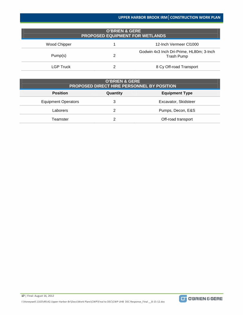
O’BRIEN & GERE PROPOSED EQUIPMENT FOR WETLANDS
Item Quantity Equipment Type
Excavator w/thumb attachment 1 PC 178 Or Equivalent
Skidsteer 2 C30, Tracked Or Equivalent
Brush Cutter 1 Bradco 72-Inch
UPPER HARBOR BROOK IRM│CONSTRUCTION WORK PLAN
17 | Final: August 16, 2012
I:\Honeywell.1163\49142.Upper-Harbor-Br\Docs\Work Plans\CWP\Final to DEC\CWP UHB DEC Response_Final __8-15-12.doc
O’BRIEN & GERE PROPOSED EQUIPMENT FOR WETLANDS
Wood Chipper 1 12-Inch Vermeer Cl1000
Pump(s) 2 Godwin 4x3 Inch Dri-Prime, HL80m; 3-Inch
Trash Pump
LGP Truck 2 8 Cy Off-road Transport
O’BRIEN & GERE PROPOSED DIRECT HIRE PERSONNEL BY POSITION
Position Quantity Equipment Type
Equipment Operators 3 Excavator, Skidsteer
Laborers 2 Pumps, Decon, E&S
Teamster 2 Off-road transport
UPPER HARBOR BROOK IRM│CONSTRUCTION WORK PLAN
18 | Final: August 16, 2012
I:\Honeywell.1163\49142.Upper-Harbor-Br\Docs\Work Plans\CWP\Final to DEC\CWP UHB DEC Response_Final __8-15-12.doc
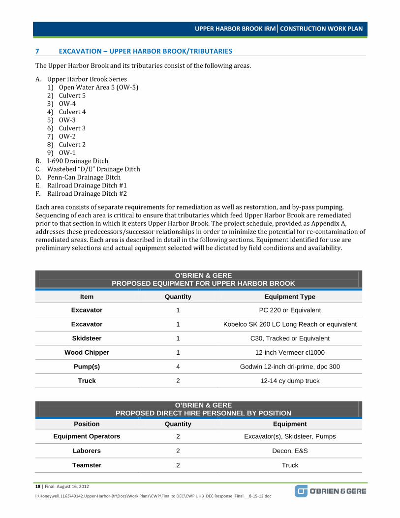
7 EXCAVATION – UPPER HARBOR BROOK/TRIBUTARIES
The Upper Harbor Brook and its tributaries consist of the following areas.
A. Upper Harbor Brook Series 1) Open Water Area 5 (OW-5) 2) Culvert 5 3) OW-4 4) Culvert 4 5) OW-3 6) Culvert 3 7) OW-2 8) Culvert 2 9) OW-1
B. I-690 Drainage Ditch C. Wastebed “D/E” Drainage Ditch D. Penn-Can Drainage Ditch E. Railroad Drainage Ditch #1 F. Railroad Drainage Ditch #2
Each area consists of separate requirements for remediation as well as restoration, and by-pass pumping. Sequencing of each area is critical to ensure that tributaries which feed Upper Harbor Brook are remediated prior to that section in which it enters Upper Harbor Brook. The project schedule, provided as Appendix A, addresses these predecessors/successor relationships in order to minimize the potential for re-contamination of remediated areas. Each area is described in detail in the following sections. Equipment identified for use are preliminary selections and actual equipment selected will be dictated by field conditions and availability.
O’BRIEN & GERE PROPOSED EQUIPMENT FOR UPPER HARBOR BROOK
Item Quantity Equipment Type
Excavator 1 PC 220 or Equivalent
Excavator 1 Kobelco SK 260 LC Long Reach or equivalent
Skidsteer 1 C30, Tracked or Equivalent
Wood Chipper 1 12-inch Vermeer cl1000
Pump(s) 4 Godwin 12-inch dri-prime, dpc 300
Truck 2 12-14 cy dump truck
O’BRIEN & GERE PROPOSED DIRECT HIRE PERSONNEL BY POSITION
Position Quantity Equipment
Equipment Operators 2 Excavator(s), Skidsteer, Pumps
Laborers 2 Decon, E&S
Teamster 2 Truck

UPPER HARBOR BROOK IRM│CONSTRUCTION WORK PLAN
19 | Final: August 16, 2012
I:\Honeywell.1163\49142.Upper-Harbor-Br\Docs\Work Plans\CWP\Final to DEC\CWP UHB DEC Response_Final __8-15-12.doc
A. Upper Harbor Brook
1) Open Water Area -5
a. Required Work Effort: Remove approximately 4 inches of sediment from ditch bottom which is limestone lined. Removal of limestone is not required.
b. Clearing: Minimal clearing is required along the western/southern bank where an access road will be needed. A skidsteer with a brush attachment will be used along with chain saws as appropriate. Native material will be chipped and left onsite to be used as stabilization cover.
c. By-Pass pumping setup is installed for OW-5 and RR ditch #2. Setup is described in Section 5. d. Once the by-pass pumping has been activated, the sediment found along the ditch profile will be
removed by a skidsteer to a single stockpile. e. Stockpiled material will be removed by an excavator located at the top of the embankment and
direct loaded onto a tandem dump truck for transport to Wastebed B. f. The channel will be flushed of residual sediment towards Culvert 5. g. The channel bottom will be inspected for seeps.
2) Culvert 5
a. Required Work Effort: Remove approximately 4 inches of sediment from culvert bottom and inspect culvert for leakage. Culvert #5 is a 7.5 foot by 8 foot concrete dual barrel culvert which is 126 feet in length.
b. Clearing: No clearing required. c. By-Pass pumping setup is in place for Culvert 5 from OW-5 installation. Setup is described in
Section 5. d. Sediment will be removed using skidsteers and placed in a single stockpile. e. Stockpiled material will be removed by an excavator and direct loaded onto a 12 to 14 cubic
yard (CY) tandem dump truck. f. The channel will be flushed towards OW-4 to remove residual sediment. g. Once cleaned of sediment, the culvert will be visually inspected for leakage. The inspection will
be video recorded.
3) Open Water Area -4
a. Required Work Effort: Remove approximately 8 inches of sediment from ditch bottom, remove limestone block from ditch, excavate approximately 6 feet of soil, liner system installation and Restoration.
b. Clearing: Removal of embankment trees and brush as required to access ditch from the west bank.
c. Cleared native material will be chipped and utilized as stabilization cover. d. By-Pass pumping setup is installed for OW-4 and RR ditch #1. Setup is described in Section 5. e. Sediment will be removed using skidsteers and placed into a single stockpile. f. Stockpiled material will be removed by an excavator located at the top of the embankment and
direct loaded onto a tandem dump truck. g. Removal of limestone blocks using a long reach excavator for transport to Wastebed B. h. Excavation by a long reach excavator of the ditch bottom to an approximate depth of 6 feet to
remove soil. Final depth is determined by the engineer. Excavated material will be loaded into a 12 to 14 cubic yard (CY) tandem dump truck for transport to Wastebed B. Soil exhibiting staining and odor will be segregated and tested. Please refer to Section 11.1 “Excavation and Transport of Materials from Upper Harbor Brook “for specific analysis conducted.
i. Backfill of excavation with embankment material to previous grade. j. The installation of a 40 mil geomembrane liner placed between 2 layers of 16 oz geocushion. A
geogrid layer is placed onto the geocushion. k. The liner system will be anchored into embankment keyways.
UPPER HARBOR BROOK IRM│CONSTRUCTION WORK PLAN
20 | Final: August 16, 2012
I:\Honeywell.1163\49142.Upper-Harbor-Br\Docs\Work Plans\CWP\Final to DEC\CWP UHB DEC Response_Final __8-15-12.doc
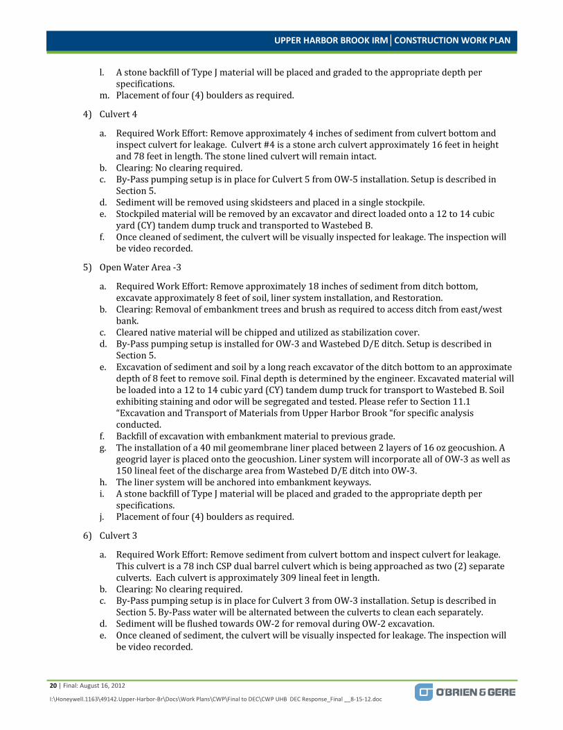
l. A stone backfill of Type J material will be placed and graded to the appropriate depth per specifications.
m. Placement of four (4) boulders as required.
4) Culvert 4
a. Required Work Effort: Remove approximately 4 inches of sediment from culvert bottom and inspect culvert for leakage. Culvert #4 is a stone arch culvert approximately 16 feet in height and 78 feet in length. The stone lined culvert will remain intact.
b. Clearing: No clearing required. c. By-Pass pumping setup is in place for Culvert 5 from OW-5 installation. Setup is described in
Section 5. d. Sediment will be removed using skidsteers and placed in a single stockpile. e. Stockpiled material will be removed by an excavator and direct loaded onto a 12 to 14 cubic
yard (CY) tandem dump truck and transported to Wastebed B. f. Once cleaned of sediment, the culvert will be visually inspected for leakage. The inspection will
be video recorded.
5) Open Water Area -3
a. Required Work Effort: Remove approximately 18 inches of sediment from ditch bottom, excavate approximately 8 feet of soil, liner system installation, and Restoration.
b. Clearing: Removal of embankment trees and brush as required to access ditch from east/west bank.
c. Cleared native material will be chipped and utilized as stabilization cover. d. By-Pass pumping setup is installed for OW-3 and Wastebed D/E ditch. Setup is described in
Section 5. e. Excavation of sediment and soil by a long reach excavator of the ditch bottom to an approximate
depth of 8 feet to remove soil. Final depth is determined by the engineer. Excavated material will be loaded into a 12 to 14 cubic yard (CY) tandem dump truck for transport to Wastebed B. Soil exhibiting staining and odor will be segregated and tested. Please refer to Section 11.1 “Excavation and Transport of Materials from Upper Harbor Brook “for specific analysis conducted.
f. Backfill of excavation with embankment material to previous grade. g. The installation of a 40 mil geomembrane liner placed between 2 layers of 16 oz geocushion. A
geogrid layer is placed onto the geocushion. Liner system will incorporate all of OW-3 as well as 150 lineal feet of the discharge area from Wastebed D/E ditch into OW-3.
h. The liner system will be anchored into embankment keyways. i. A stone backfill of Type J material will be placed and graded to the appropriate depth per
specifications. j. Placement of four (4) boulders as required.
6) Culvert 3
a. Required Work Effort: Remove sediment from culvert bottom and inspect culvert for leakage. This culvert is a 78 inch CSP dual barrel culvert which is being approached as two (2) separate culverts. Each culvert is approximately 309 lineal feet in length.
b. Clearing: No clearing required. c. By-Pass pumping setup is in place for Culvert 3 from OW-3 installation. Setup is described in
Section 5. By-Pass water will be alternated between the culverts to clean each separately. d. Sediment will be flushed towards OW-2 for removal during OW-2 excavation. e. Once cleaned of sediment, the culvert will be visually inspected for leakage. The inspection will
be video recorded.

UPPER HARBOR BROOK IRM│CONSTRUCTION WORK PLAN
21 | Final: August 16, 2012
I:\Honeywell.1163\49142.Upper-Harbor-Br\Docs\Work Plans\CWP\Final to DEC\CWP UHB DEC Response_Final __8-15-12.doc
7) Open Water Area -2
a. Required Work Effort: Remove approximately 6 inches of sediment from ditch bottom, excavate approximately 2 feet of contaminated soil and remove to Wastebed B, liner system installation and Restoration.
b. Clearing: Removal of embankment brush as required to access ditch from east/west bank. c. Cleared material will be chipped and utilized as stabilization cover. d. By-Pass pumping setup is installed for OW-2. Setup is described in Section 5. e. Excavation of sediment and contaminated soil by a long reach excavator of the ditch bottom to
an approximate depth of 2.5 feet to remove impacted soil. Final depth is determined by the engineer. Excavated material will be loaded into a 12 to 14 cubic yard (CY) tandem dump truck for transport to Wastebed B.
f. Soil exhibiting staining and odor will be segregated and tested. Please refer to Section 11.1 “Excavation and Transport of Materials from Upper Harbor Brook “for specific analysis conducted.
g. The installation of a 40 mil geomembrane liner placed between 2 layers of 16 oz geocushion. A geogrid layer is placed onto the geocushion. Liner system will incorporate all of OW-2 as well as up the embankment slopes.
h. The liner system will be anchored into embankment keyways. i. A stone backfill of Type K material will be placed and graded to the appropriate depth per
specifications. j. Placement and filling of Gabion Mattress along south slope of embankment. k. Place 6 inches of topsoil and hydro-seed in appropriate areas.
8) Culvert 2
a. Required Work Effort: Remove sediment from culvert bottom and inspect culvert for leakage. This culvert is a 16 foot by 5 foot or 7.5 foot concrete box culvert. The culvert is approximately 111 lineal feet in length.
b. Clearing: No clearing required. c. By-Pass pumping setup is in place for Culvert 2 from OW-3 installation. Setup is described in
Section 5. d. Sediment will be flushed towards OW-1 for removal during OW-1 excavation. e. Once cleaned of sediment, the culvert will be visually inspected for leakage. The inspection will
be video recorded.
9) Open Water Area -1
a. Required Work Effort: Remove approximately 2 feet of sediment from ditch bottom, excavate approximately 4 feet of contaminated soil and remove to Wastebed “B”, liner system installation, and Restoration.
b. Clearing: Removal of embankment brush as required to access ditch from east/west bank. c. Cleared material will be chipped and utilized as stabilization cover. d. By-Pass pumping setup is installed for OW-1. Setup is described in Section 5. e. Excavation of sediment and contaminated soil by a long reach excavator of the ditch bottom to
an approximate depth of 6 feet to remove impacted soil. Final depth is determined by the engineer. Excavated material will be loaded into a 12 to 14 cubic yard (CY) tandem dump truck for transport to Wastebed B.
f. Soil exhibiting staining and odor will be segregated and tested. Please refer to Section 11.1 “Excavation and Transport of Materials from Upper Harbor Brook “for specific analysis conducted.

UPPER HARBOR BROOK IRM│CONSTRUCTION WORK PLAN
22 | Final: August 16, 2012
I:\Honeywell.1163\49142.Upper-Harbor-Br\Docs\Work Plans\CWP\Final to DEC\CWP UHB DEC Response_Final __8-15-12.doc
g. The installation of a 40 mil geomembrane liner placed between 2 layers of 16 oz geocushion. A geogrid layer is placed onto the geocushion. Liner system will incorporate all of OW-1 as well as up the embankment slopes.
h. The liner system will be anchored into embankment keyways. i. A stone backfill of Type K material will be placed and graded to the appropriate depth per
specifications. j. Place 6 inches of topsoil and hydro-seed in appropriate areas.
B. I-690 Drainage Ditch
The I-690 drainage ditch is parallel to I-690 at the toe of the northern embankment. It is approximately 1,500 feet in length and varies in width. The ditch drains runoff from the elevated roadway as well as a series of catch basins located along the roadway through a 24 inch RCP discharge at approximate station 5+75. The remediation effort of this ditch includes the installation of a collection pipe system which will discharge into Pump Station 2 for pumping to the Lakeshore Pump Station and ultimately to the Willis/Semet Groundwater Treatment Plant. Wetland area WL-6 adjoins the ditch at approximate station 12+00 and ends at the top of embankment to OW-1. The remediation of this wetland is discussed in Section 6 of this work plan. The equipment required to execute this remediation program is similar to that used in the wetland remediation/restoration efforts and is listed below. Equipment identified for use are preliminary selections and actual equipment selected will be dictated by field conditions and availability.
Cleaning and inspection of the storm sewer pipe is a component of the overall project and will be conducted prior to the installation of the collection trench in the I-690 ditch. The work effort will be to flush the existing catch basins, piping, culverts and other appurtenances for the approximate length of 1733 LF. The sediment resulting from cleaning operation will be contained within 22,000 gallon frac tanks equipped with an internal weir which will remove the majority of the sediment in the collection vault and permit overflow of water into the main tank body. Additional settling will occur in the main tank compartment. Discharge water from the main tank will flow through a 25 micron bag filter, if required in order to meet a “visually clean” standard prior to being pumped into a vacuum truck for deposit into a sump which is connected to the Lakeshore Pumping Station. Sediment which remains in the frac tank compartments will be removed, allowed to dewater within a confined sediment basin and placed within Wastebed B. The contaminated water obtained from the confined sediment basin will be pumped into the existing weir tank where it will pass over the weir and discharge through the bag filter into a vacuum truck for pump-out into one of the vaults which is connected to the Lakeshore Pumping Station.
Upon the completion of the storm sewer flushing, closed circuit television recording of the cleaned area will be conducted to determine any groundwater infiltration and/or structure damage. Should infiltration be observed, sealing of the area is required. Note 4 of Drawing G-31 lists several approved methods for sealing. A determination of which method is most appropriate will be identified at that time.
Following that table is a sequential listing which will identify the work effort to complete this project.
O’BRIEN & GERE PROPOSED EQUIPMENT FOR I-690 DITCH
Item Quantity Equipment Type Excavator w/thumb
attachment 2 PC 178 or Equivalent
Skidsteer 1 C30, tracked or equivalent
Brush Cutter 1 Bradco 72-inch
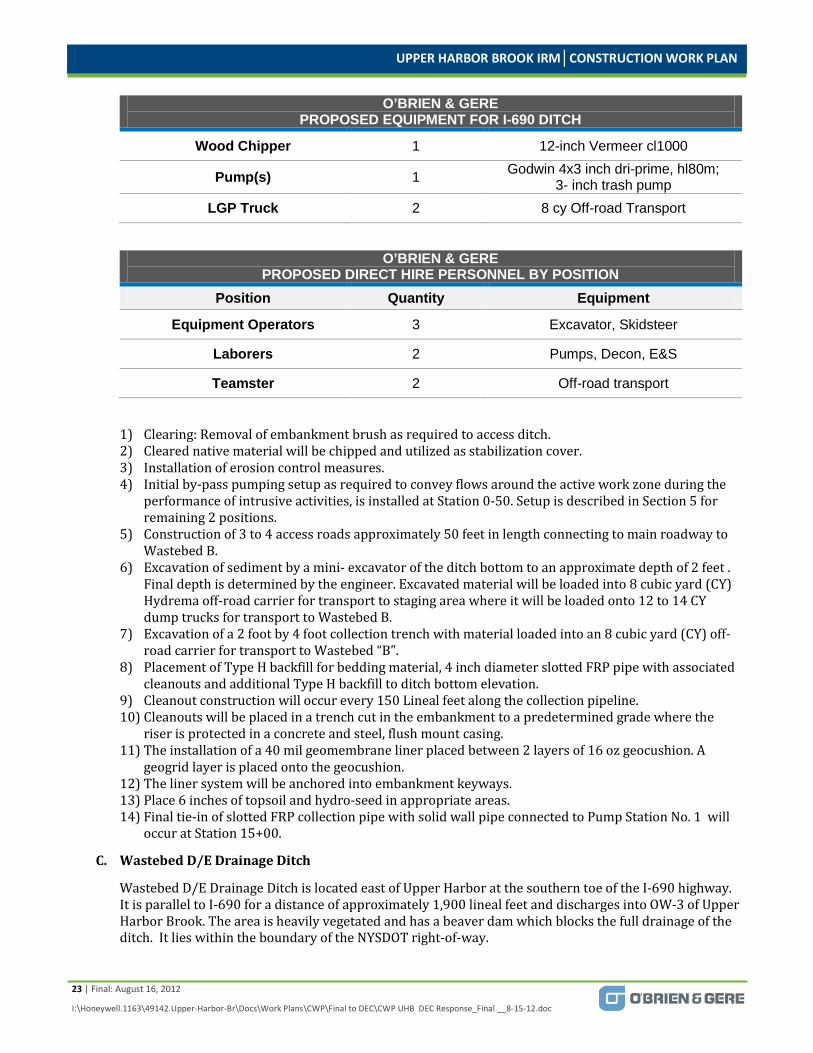
UPPER HARBOR BROOK IRM│CONSTRUCTION WORK PLAN
23 | Final: August 16, 2012
I:\Honeywell.1163\49142.Upper-Harbor-Br\Docs\Work Plans\CWP\Final to DEC\CWP UHB DEC Response_Final __8-15-12.doc
O’BRIEN & GERE PROPOSED EQUIPMENT FOR I-690 DITCH
Wood Chipper 1 12-inch Vermeer cl1000
Pump(s) 1 Godwin 4x3 inch dri-prime, hl80m; 3- inch trash pump
LGP Truck 2 8 cy Off-road Transport
O’BRIEN & GERE PROPOSED DIRECT HIRE PERSONNEL BY POSITION
Position Quantity Equipment
Equipment Operators 3 Excavator, Skidsteer
Laborers 2 Pumps, Decon, E&S
Teamster 2 Off-road transport
1) Clearing: Removal of embankment brush as required to access ditch. 2) Cleared native material will be chipped and utilized as stabilization cover. 3) Installation of erosion control measures. 4) Initial by-pass pumping setup as required to convey flows around the active work zone during the
performance of intrusive activities, is installed at Station 0-50. Setup is described in Section 5 for remaining 2 positions.
5) Construction of 3 to 4 access roads approximately 50 feet in length connecting to main roadway to Wastebed B.
6) Excavation of sediment by a mini- excavator of the ditch bottom to an approximate depth of 2 feet . Final depth is determined by the engineer. Excavated material will be loaded into 8 cubic yard (CY) Hydrema off-road carrier for transport to staging area where it will be loaded onto 12 to 14 CY dump trucks for transport to Wastebed B.
7) Excavation of a 2 foot by 4 foot collection trench with material loaded into an 8 cubic yard (CY) off-road carrier for transport to Wastebed “B”.
8) Placement of Type H backfill for bedding material, 4 inch diameter slotted FRP pipe with associated cleanouts and additional Type H backfill to ditch bottom elevation.
9) Cleanout construction will occur every 150 Lineal feet along the collection pipeline. 10) Cleanouts will be placed in a trench cut in the embankment to a predetermined grade where the
riser is protected in a concrete and steel, flush mount casing. 11) The installation of a 40 mil geomembrane liner placed between 2 layers of 16 oz geocushion. A
geogrid layer is placed onto the geocushion. 12) The liner system will be anchored into embankment keyways. 13) Place 6 inches of topsoil and hydro-seed in appropriate areas. 14) Final tie-in of slotted FRP collection pipe with solid wall pipe connected to Pump Station No. 1 will
occur at Station 15+00.
C. Wastebed D/E Drainage Ditch
Wastebed D/E Drainage Ditch is located east of Upper Harbor at the southern toe of the I-690 highway. It is parallel to I-690 for a distance of approximately 1,900 lineal feet and discharges into OW-3 of Upper Harbor Brook. The area is heavily vegetated and has a beaver dam which blocks the full drainage of the ditch. It lies within the boundary of the NYSDOT right-of-way.

UPPER HARBOR BROOK IRM│CONSTRUCTION WORK PLAN
24 | Final: August 16, 2012
I:\Honeywell.1163\49142.Upper-Harbor-Br\Docs\Work Plans\CWP\Final to DEC\CWP UHB DEC Response_Final __8-15-12.doc
Anticipated work effort includes clearing of vegetation within the limits of excavation. This material will be chipped or shredded for use as stabilization material where appropriate. An access roadway will be constructed for an approximate 300 feet of length parallel to the ditch along the northern edge. This roadway will be utilized for transport of the excavated material to Wastebed B with 12 to 14 CY dump trucks. The roadway cannot extend any further along the ditch as the I-690 embankment extends towards the crest of the ditch at approximate Station 3+20. Material excavated from Sta. 3+00 to 19+00 will be transported by Low Ground Pressure transports along the ditch centerline using mats if necessary. By-Pass water management requires 4 separate setups as described in Section 5, Water Management. Ditch excavation will be two (2) feet of depth along the profile as identified on sheet G-37 of the contract drawings.
Restoration activities will consist of placing Sennet Bank Run fill to match existing grades from Station 1+50 to 19+00. The final 150 feet of ditch that discharges into OW-3 will have a liner system installed which is merged with the OW-3 liner system. The equipment required to execute this remediation program is similar to that used in the wetland remediation/restoration efforts and is listed below. Equipment identified for use are preliminary selections and actual equipment selected will be dictated by field conditions and availability. Following that table is a sequential listing which will identify the work effort to complete this project.
O’BRIEN & GERE PROPOSED EQUIPMENT FOR WASTEBED D/E DITCH
Item Quantity Equipment Type Excavator w/thumb
attachment 2 Pc 178 Or Equivalent; Pc-210 Or Equivalent
Skidsteer 1 C30, Tracked Or Equivalent
Brush Cutter 1 Bradco 72 Inch
Wood Chipper 1 12 Inch Vermeer Cl1000
Pump(s) 1 Godwin 4x3 Inch Dri-Prime, Hl80m; 3 Inch Trash Pump
LGP Truck 2 8 Cy Off-road Transport
Trucks 1 12-14 Cy
O’BRIEN & GERE PROPOSED DIRECT HIRE PERSONNEL BY POSITION
Position Quantity Equipment
Equipment Operators 2 Excavator, Skidsteer
Laborers 2 Pumps, Decon, E&S
Teamster 3 Off-road transports/Dump Trucks
1) Clearing: Removal of embankment brush as required to access ditch. 2) Cleared native material will be chipped and utilized as stabilization cover. 3) Installation of erosion control measures. 4) Initial by-pass pumping setup is installed as required to convey flows around the active work zone
during the performance of intrusive activities at Station 19+50. Setup is described in Section 5 for remaining 3 positions.
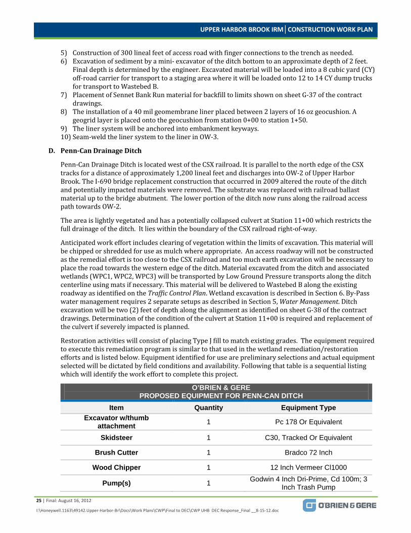
UPPER HARBOR BROOK IRM│CONSTRUCTION WORK PLAN
25 | Final: August 16, 2012
I:\Honeywell.1163\49142.Upper-Harbor-Br\Docs\Work Plans\CWP\Final to DEC\CWP UHB DEC Response_Final __8-15-12.doc
5) Construction of 300 lineal feet of access road with finger connections to the trench as needed. 6) Excavation of sediment by a mini- excavator of the ditch bottom to an approximate depth of 2 feet.
Final depth is determined by the engineer. Excavated material will be loaded into a 8 cubic yard (CY) off-road carrier for transport to a staging area where it will be loaded onto 12 to 14 CY dump trucks for transport to Wastebed B.
7) Placement of Sennet Bank Run material for backfill to limits shown on sheet G-37 of the contract drawings.
8) The installation of a 40 mil geomembrane liner placed between 2 layers of 16 oz geocushion. A geogrid layer is placed onto the geocushion from station 0+00 to station 1+50.
9) The liner system will be anchored into embankment keyways. 10) Seam-weld the liner system to the liner in OW-3.
D. Penn-Can Drainage Ditch
Penn-Can Drainage Ditch is located west of the CSX railroad. It is parallel to the north edge of the CSX tracks for a distance of approximately 1,200 lineal feet and discharges into OW-2 of Upper Harbor Brook. The I-690 bridge replacement construction that occurred in 2009 altered the route of the ditch and potentially impacted materials were removed. The substrate was replaced with railroad ballast material up to the bridge abutment. The lower portion of the ditch now runs along the railroad access path towards OW-2.
The area is lightly vegetated and has a potentially collapsed culvert at Station 11+00 which restricts the full drainage of the ditch. It lies within the boundary of the CSX railroad right-of-way.
Anticipated work effort includes clearing of vegetation within the limits of excavation. This material will be chipped or shredded for use as mulch where appropriate. An access roadway will not be constructed as the remedial effort is too close to the CSX railroad and too much earth excavation will be necessary to place the road towards the western edge of the ditch. Material excavated from the ditch and associated wetlands (WPC1, WPC2, WPC3) will be transported by Low Ground Pressure transports along the ditch centerline using mats if necessary. This material will be delivered to Wastebed B along the existing roadway as identified on the Traffic Control Plan. Wetland excavation is described in Section 6. By-Pass water management requires 2 separate setups as described in Section 5, Water Management. Ditch excavation will be two (2) feet of depth along the alignment as identified on sheet G-38 of the contract drawings. Determination of the condition of the culvert at Station 11+00 is required and replacement of the culvert if severely impacted is planned.
Restoration activities will consist of placing Type J fill to match existing grades. The equipment required to execute this remediation program is similar to that used in the wetland remediation/restoration efforts and is listed below. Equipment identified for use are preliminary selections and actual equipment selected will be dictated by field conditions and availability. Following that table is a sequential listing which will identify the work effort to complete this project.
O’BRIEN & GERE PROPOSED EQUIPMENT FOR PENN-CAN DITCH
Item Quantity Equipment Type Excavator w/thumb
attachment 1 Pc 178 Or Equivalent
Skidsteer 1 C30, Tracked Or Equivalent
Brush Cutter 1 Bradco 72 Inch
Wood Chipper 1 12 Inch Vermeer Cl1000
Pump(s) 1 Godwin 4 Inch Dri-Prime, Cd 100m; 3 Inch Trash Pump

UPPER HARBOR BROOK IRM│CONSTRUCTION WORK PLAN
26 | Final: August 16, 2012
I:\Honeywell.1163\49142.Upper-Harbor-Br\Docs\Work Plans\CWP\Final to DEC\CWP UHB DEC Response_Final __8-15-12.doc
O’BRIEN & GERE PROPOSED EQUIPMENT FOR PENN-CAN DITCH
LGP Truck 2 8 Cy Off-road Transport
O’BRIEN & GERE PROPOSED DIRECT HIRE PERSONNEL BY POSITION
Position Quantity Equipment
Equipment Operators 2 Excavator, Skidsteer
Laborers 2 Pumps, Decon, E&S
Teamster 2 Off road Transports/Dump Trucks
1) Clearing: Removal of embankment brush as required to access ditch. 2) Cleared native material will be chipped and utilized as stabilization cover. 3) Installation of erosion control measures. 4) Initial by-pass pumping setup is installed as required to convey flows around the active work zone
during the performance of intrusive activities at Station 2+50. Setup is described in Section 5 for the remaining position. WPC3 is part of the Penn-Can ditch prior to station 2+50 and that part of the ditch will be remediated during WPC3 efforts as described in the Wetlands section of the work plan.
5) Excavation of sediment by a mini- excavator of the ditch bottom to an approximate depth of 2 feet. Final depth is determined by the engineer. Excavated material will be loaded into a 8 cubic yard (CY) off-road carrier for transport to Wastebed B.
6) Placement of Type J material for backfill to limits shown on sheet G-38 of the contract drawings.
E. Railroad Drainage Ditch #1
Railroad Drainage Ditch #1 is located within a triangular area bordered on all three sides by CSX railroad and Susquehanna railroad lines. It is separated into sections based on a 24 inch concrete culvert beneath the Susquehanna rail line. The east section is approximately 135 lineal feet and the west section is approximately 600 lineal feet. The ditch discharges into OW-4. Wetland WRR2 is centered in the west section for approximately 300 feet of its length. There is no defined ditch line alignment for the west portion of the ditch from Station 0+00 to Station 3+00. A field determination of the ditch commencement will be done in conjunction with O’Brien & Gere wetland ecologists.
The anticipated work effort includes clearing of the vegetation within the excavation limits of the ditch and the wetland WRR2. Excavation depths are 2 feet for both the ditch and the wetland. Excavation of both areas will be done concurrently. Wetland excavation is also described in Section 6. Minimal road construction for access is anticipated as there are existing pathways within the area for access. Finger roads may be constructed as necessary. Removal of the sediments will be by using low ground pressure transports along the centerline of the ditch, using mats as necessary. The material will be staged for loading onto 12 to 14 CY dump trucks for transport to Wastebed B. By-Pass water management requires a single setup as described in Section 5, Water Management. The culvert requires cleaning, inspection which will be video-taped as required in the specifications and repair if damaged. All remedial work will be coordinated with the excavation of Upper Harbor Brook to minimize the potential for re-contamination of OW-4.
Restoration activities will consist of placing Sennet Bank Run fill to match existing grades within the ditch alignment. Restoration of the culvert entrance and discharge consists of constructing rip rap aprons using fabric placed as protection and light weight stone rip rap keyed into the ditch bottom. The
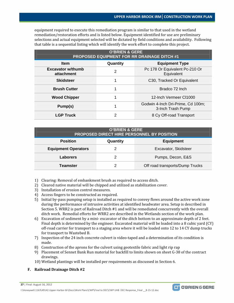
UPPER HARBOR BROOK IRM│CONSTRUCTION WORK PLAN
27 | Final: August 16, 2012
I:\Honeywell.1163\49142.Upper-Harbor-Br\Docs\Work Plans\CWP\Final to DEC\CWP UHB DEC Response_Final __8-15-12.doc
equipment required to execute this remediation program is similar to that used in the wetland remediation/restoration efforts and is listed below. Equipment identified for use are preliminary selections and actual equipment selected will be dictated by field conditions and availability. Following that table is a sequential listing which will identify the work effort to complete this project.
O’BRIEN & GERE PROPOSED EQUIPMENT FOR RR DRAINAGE DITCH #1
Item Quantity Equipment Type Excavator w/thumb
attachment 2 Pc 178 Or Equivalent Pc-210 Or Equivalent
Skidsteer 1 C30, Tracked Or Equivalent
Brush Cutter 1 Bradco 72 Inch
Wood Chipper 1 12-Inch Vermeer Cl1000
Pump(s) 1 Godwin 4-Inch Dri-Prime, Cd 100m; 3-Inch Trash Pump
LGP Truck 2 8 Cy Off-road Transport
O’BRIEN & GERE PROPOSED DIRECT HIRE PERSONNEL BY POSITION
Position Quantity Equipment
Equipment Operators 2 Excavator, Skidsteer
Laborers 2 Pumps, Decon, E&S
Teamster 2 Off road transports/Dump Trucks
1) Clearing: Removal of embankment brush as required to access ditch. 2) Cleared native material will be chipped and utilized as stabilization cover. 3) Installation of erosion control measures. 4) Access fingers to be constructed as required. 5) Initial by-pass pumping setup is installed as required to convey flows around the active work zone
during the performance of intrusive activities at identified headwater area. Setup is described in Section 5. WRR2 is part of Railroad Ditch #1 and will be remediated concurrently with the overall ditch work. Remedial efforts for WRR2 are described in the Wetlands section of the work plan.
6) Excavation of sediment by a mini- excavator of the ditch bottom to an approximate depth of 2 feet. Final depth is determined by the engineer. Excavated material will be loaded into a 8 cubic yard (CY) off-road carrier for transport to a staging area where it will be loaded onto 12 to 14 CY dump trucks for transport to Wastebed B.
7) Inspection of the 24 inch concrete culvert is video-taped and a determination of its condition is made.
8) Construction of the aprons for the culvert using geotextile fabric and light rip rap 9) Placement of Sennet Bank Run material for backfill to limits shown on sheet G-38 of the contract
drawings. 10) Wetland plantings will be installed per requirements as discussed in Section 6.
F. Railroad Drainage Ditch #2

UPPER HARBOR BROOK IRM│CONSTRUCTION WORK PLAN
28 | Final: August 16, 2012
I:\Honeywell.1163\49142.Upper-Harbor-Br\Docs\Work Plans\CWP\Final to DEC\CWP UHB DEC Response_Final __8-15-12.doc
Railroad Drainage Ditch #2 is located within a triangular area bordered on all three sides by CSX railroad and Susquehanna railroad lines. It is separated into sections based on a 36 inch concrete culvert beneath the Susquehanna rail line. The east section is approximately 86 lineal feet and the west section is approximately 550 lineal feet. The ditch discharges into OW-5. Wetland WRR3 is intertwined in the west section for approximately 75 percent of its length. The headwater for this ditch and wetland system is a culvert which exits beneath the CSX rail line on the southern border of WRR3.
The anticipated work effort includes clearing of the vegetation within the excavation limits of the ditch and the wetland WRR3. Excavation depths are 2 feet for both the ditch and the wetland. Excavation of both areas will be done concurrently. Wetland excavation is also described in Section 6. Road construction for access is required as there are few existing pathways within the area for access. Finger roads may be constructed as necessary. A crossing is required to be constructed over the Susquehanna rail line for access to the area as well. Removal of the sediments will be by using low ground pressure transports along the centerline of the ditch, using mats as necessary. The material will be staged for loading onto 12 to 14 CY dump trucks for transport to Wastebed B. In some areas it may be possible to direct load the dump trucks as they will be on a constructed roadway. Decontamination pads are constructed at each exit to public roadways. By-Pass water management requires a single setup as described in Section 5, Water Management. The culvert requires cleaning, inspection which will be video-taped as required in the specifications and repair as necessary. Remedial work will be coordinated with the excavation of Upper Harbor Brook to minimize the potential for re-contamination of OW-5.
Restoration activities will consist of placing Sennet Bank Run fill to match existing grades within the ditch alignment. Restoration of the culvert entrance and discharge consists of constructing rip rap aprons using fabric placed as protection and light weight stone rip rap keyed into the ditch bottom. The equipment required to execute this remediation program is similar to that used in the wetland remediation/restoration efforts and is listed below. Equipment identified for use are preliminary selections and actual equipment selected will be dictated by field conditions and availability. Following that table is a sequential listing which will identify the work effort to complete this project.
O’BRIEN & GERE PROPOSED EQUIPMENT FOR RR DRAINAGE DITCH #2
Item Quantity Equipment Type
Excavator w/thumb attachment 2 Pc 178 Or Equivalent Pc-210 Or
Equivalent Skidsteer 1 C30, Tracked Or Equivalent
Brush Cutter 1 Bradco 72 Inch
Wood Chipper 1 12 Inch Vermeer Cl1000
Pump(s) 1 Godwin 4-Inch Dri-Prime, Cd 100m; 3-Inch Trash Pump
Trucks 1 12-14 Cy
LGP Truck 2 8 Cy Off-road Transport
O’BRIEN & GERE PROPOSED DIRECT HIRE PERSONNEL BY POSITION
Position Quantity Equipment
Equipment Operators 2 Excavator, Skidsteer
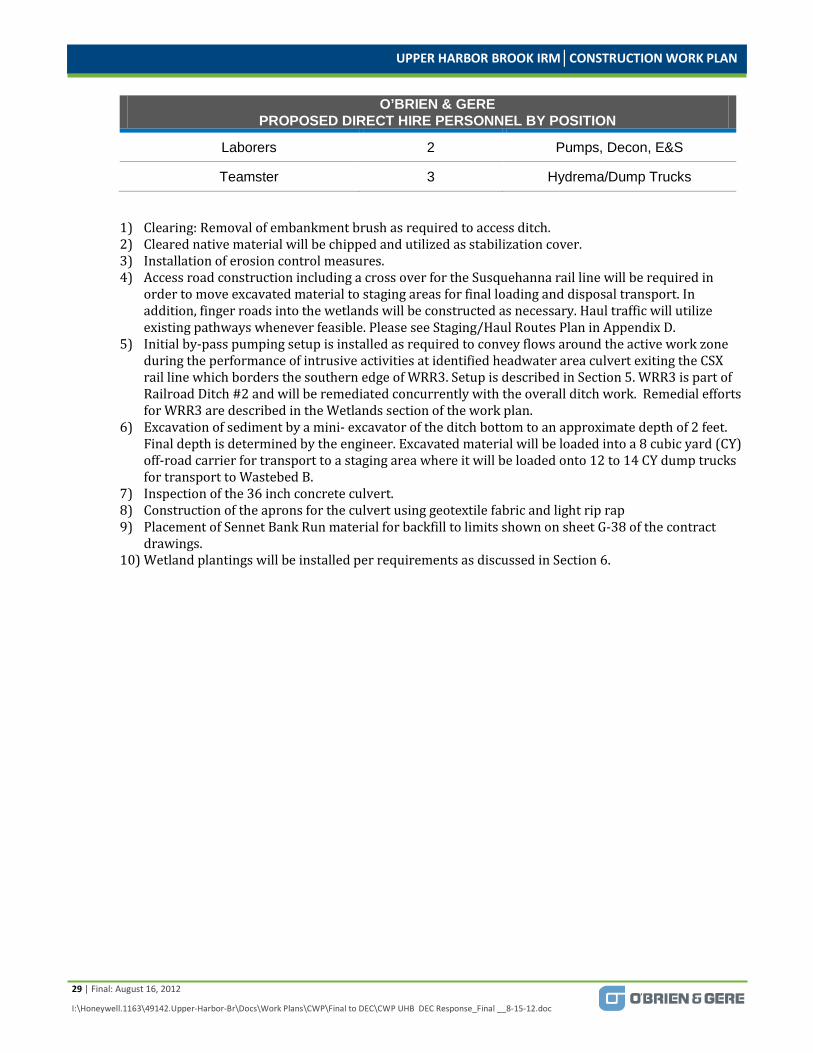
UPPER HARBOR BROOK IRM│CONSTRUCTION WORK PLAN
29 | Final: August 16, 2012
I:\Honeywell.1163\49142.Upper-Harbor-Br\Docs\Work Plans\CWP\Final to DEC\CWP UHB DEC Response_Final __8-15-12.doc
O’BRIEN & GERE PROPOSED DIRECT HIRE PERSONNEL BY POSITION
Laborers 2 Pumps, Decon, E&S
Teamster 3 Hydrema/Dump Trucks
1) Clearing: Removal of embankment brush as required to access ditch. 2) Cleared native material will be chipped and utilized as stabilization cover. 3) Installation of erosion control measures. 4) Access road construction including a cross over for the Susquehanna rail line will be required in
order to move excavated material to staging areas for final loading and disposal transport. In addition, finger roads into the wetlands will be constructed as necessary. Haul traffic will utilize existing pathways whenever feasible. Please see Staging/Haul Routes Plan in Appendix D.
5) Initial by-pass pumping setup is installed as required to convey flows around the active work zone during the performance of intrusive activities at identified headwater area culvert exiting the CSX rail line which borders the southern edge of WRR3. Setup is described in Section 5. WRR3 is part of Railroad Ditch #2 and will be remediated concurrently with the overall ditch work. Remedial efforts for WRR3 are described in the Wetlands section of the work plan.
6) Excavation of sediment by a mini- excavator of the ditch bottom to an approximate depth of 2 feet. Final depth is determined by the engineer. Excavated material will be loaded into a 8 cubic yard (CY) off-road carrier for transport to a staging area where it will be loaded onto 12 to 14 CY dump trucks for transport to Wastebed B.
7) Inspection of the 36 inch concrete culvert. 8) Construction of the aprons for the culvert using geotextile fabric and light rip rap 9) Placement of Sennet Bank Run material for backfill to limits shown on sheet G-38 of the contract
drawings. 10) Wetland plantings will be installed per requirements as discussed in Section 6.
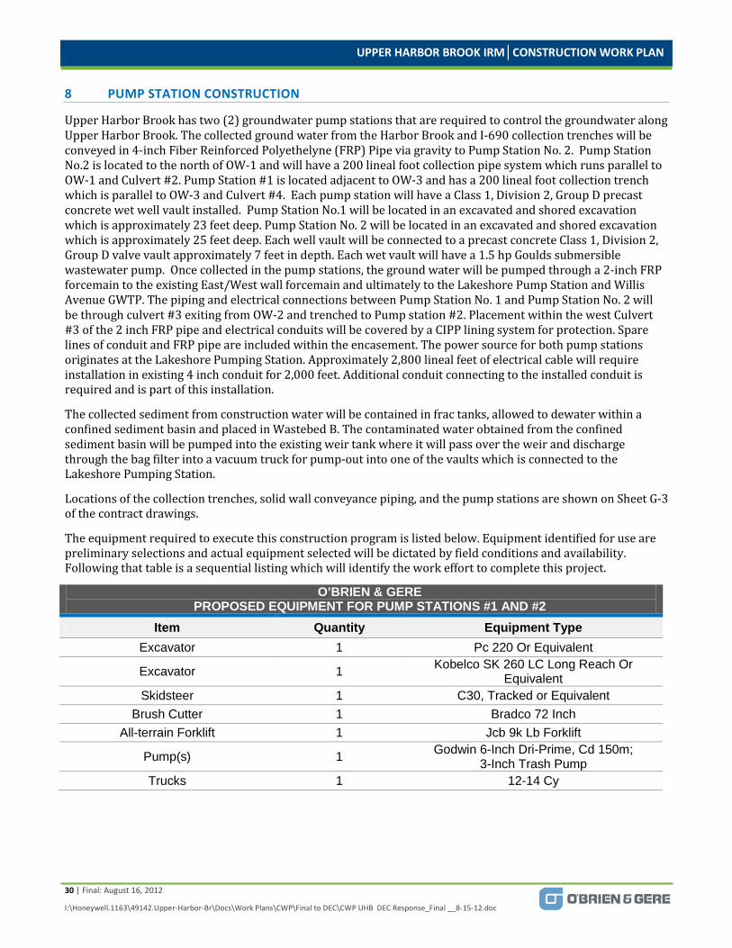
UPPER HARBOR BROOK IRM│CONSTRUCTION WORK PLAN
30 | Final: August 16, 2012
I:\Honeywell.1163\49142.Upper-Harbor-Br\Docs\Work Plans\CWP\Final to DEC\CWP UHB DEC Response_Final __8-15-12.doc
8 PUMP STATION CONSTRUCTION
Upper Harbor Brook has two (2) groundwater pump stations that are required to control the groundwater along Upper Harbor Brook. The collected ground water from the Harbor Brook and I-690 collection trenches will be conveyed in 4-inch Fiber Reinforced Polyethelyne (FRP) Pipe via gravity to Pump Station No. 2. Pump Station No.2 is located to the north of OW-1 and will have a 200 lineal foot collection pipe system which runs parallel to OW-1 and Culvert #2. Pump Station #1 is located adjacent to OW-3 and has a 200 lineal foot collection trench which is parallel to OW-3 and Culvert #4. Each pump station will have a Class 1, Division 2, Group D precast concrete wet well vault installed. Pump Station No.1 will be located in an excavated and shored excavation which is approximately 23 feet deep. Pump Station No. 2 will be located in an excavated and shored excavation which is approximately 25 feet deep. Each well vault will be connected to a precast concrete Class 1, Division 2, Group D valve vault approximately 7 feet in depth. Each wet vault will have a 1.5 hp Goulds submersible wastewater pump. Once collected in the pump stations, the ground water will be pumped through a 2-inch FRP forcemain to the existing East/West wall forcemain and ultimately to the Lakeshore Pump Station and Willis Avenue GWTP. The piping and electrical connections between Pump Station No. 1 and Pump Station No. 2 will be through culvert #3 exiting from OW-2 and trenched to Pump station #2. Placement within the west Culvert #3 of the 2 inch FRP pipe and electrical conduits will be covered by a CIPP lining system for protection. Spare lines of conduit and FRP pipe are included within the encasement. The power source for both pump stations originates at the Lakeshore Pumping Station. Approximately 2,800 lineal feet of electrical cable will require installation in existing 4 inch conduit for 2,000 feet. Additional conduit connecting to the installed conduit is required and is part of this installation.
The collected sediment from construction water will be contained in frac tanks, allowed to dewater within a confined sediment basin and placed in Wastebed B. The contaminated water obtained from the confined sediment basin will be pumped into the existing weir tank where it will pass over the weir and discharge through the bag filter into a vacuum truck for pump-out into one of the vaults which is connected to the Lakeshore Pumping Station.
Locations of the collection trenches, solid wall conveyance piping, and the pump stations are shown on Sheet G-3 of the contract drawings.
The equipment required to execute this construction program is listed below. Equipment identified for use are preliminary selections and actual equipment selected will be dictated by field conditions and availability. Following that table is a sequential listing which will identify the work effort to complete this project.
O’BRIEN & GERE PROPOSED EQUIPMENT FOR PUMP STATIONS #1 AND #2
Item Quantity Equipment Type Excavator 1 Pc 220 Or Equivalent
Excavator 1 Kobelco SK 260 LC Long Reach Or Equivalent
Skidsteer 1 C30, Tracked or Equivalent Brush Cutter 1 Bradco 72 Inch
All-terrain Forklift 1 Jcb 9k Lb Forklift
Pump(s) 1 Godwin 6-Inch Dri-Prime, Cd 150m; 3-Inch Trash Pump
Trucks 1 12-14 Cy

UPPER HARBOR BROOK IRM│CONSTRUCTION WORK PLAN
31 | Final: August 16, 2012
I:\Honeywell.1163\49142.Upper-Harbor-Br\Docs\Work Plans\CWP\Final to DEC\CWP UHB DEC Response_Final __8-15-12.doc
O’BRIEN & GERE PROPOSED DIRECT HIRE PERSONNEL AND SUBCONTRACTORS BY POSITION
Position Quantity Equipment
Equipment Operators 2 Excavator, Skidsteer, Pumps
Laborers 2 Pumps, E&S Teamster 1 Dump Truck Pipefitters 3 Mechanical Piping
Excavation Support 1 Sheetpile Contractor Electrical 1 Electrical Contractor
A. Clearing: Removal of embankment brush as required to access ditch. B. Cleared material will be chipped and utilized as stabilization cover. C. Installation of erosion control measures. D. Access road construction will be minimal as roads will have been constructed for access to other areas of
work. Haul traffic will utilize existing pathways whenever feasible. Please see Staging/Haul Routes Plan in Appendix D.
E. Install sheetpile on 20 foot square for wet well installation support. F. Excavation of wet well will be in stages. There are 3 levels of walers for support of the sheetpile installation.
Between each waler installation there will be excavation of the cell to the next level of walers. This will occur until all 3 levels are installed and the base excavated and leveled.
G. Installation of 12 inches of drainage stone. H. Installation of 12 inch thick concrete mud mat. I. Construction water pumping setup is installed and water pumped to Frac tank. J. Installation of precast concrete well vault. K. Installation of precast concrete valve vault. L. Mechanical equipment installation. M. Electrical equipment installation. N. Excavation of a 2 foot by 4 foot collection trench with material loaded into 8 cubic yard (CY) Hydrema off-
road carrier for transport to Wastebed B. O. Placement of Type H backfill for bedding material, 4 inch diameter slotted FRP pipe with associated
cleanouts and additional Type H backfill to ditch bottom elevation. P. Cleanouts will be in a concrete and steel, flush mount casing. Q. Install 2 inch force main piping and electrical conduits through west branch of Culvert #3. R. Install CIPP lining material in west branch of Culvert #3. S. Excavate trench for force main piping. T. Install 2 inch force main piping and cleanouts per details on sheet G-32 of contract drawings. U. Place 6 inches of topsoil and hydro-seed in appropriate areas. V. Final tie-in of slotted FRP collection pipe from I-690 ditch system with solid wall pipe connected to the well
vault will occur at Station 15+00 for pump station #2.
UPPER HARBOR BROOK IRM│CONSTRUCTION WORK PLAN
32 | Final: August 16, 2012
I:\Honeywell.1163\49142.Upper-Harbor-Br\Docs\Work Plans\CWP\Final to DEC\CWP UHB DEC Response_Final __8-15-12.doc
9 STARTUP AND COMMISSIONING
In addition to design and construction management, O’Brien & Gere will provide commissioning services to confirm proper operation of the Upper Harbor Brook (UHB) recovery systems components.
9.1 COMMISSIONING PLAN
O’Brien & Gere will develop a commissioning plan. The purpose of the commissioning plan is to identify the overall strategy that will be implemented to start-up the UHB recovery systems. Implementation of the Commissioning Plan will be a team effort, led by the Commissioning Manager, with input from the project management team and Honeywell. At a minimum, the Commissioning Plan will include:
A. Identify commissioning team roles and responsibilities
B. System operation description
C. Incorporate commissioning schedule into overall construction schedule
D. Develop the Installation Commissioning (IC) Process
E. Develop the Operational Commissioning (OC) Process
9.1.1 Installation Commissioning (IC) Protocol The IC Protocol will be developed based on project equipment specifications and drawings. The IC is a “dry” test and will demonstrate:
1) Verification that installed components comply with design documents
2) Verify and document requisite pre-start up testing (e.g., hydrostatic, hi-pot, loop, etc.) has been successfully completed
3) Verify and document process instruments are properly calibrated and outputs are ranged properly
4) Verify installed process equipment is properly tagged
5) Verify electrical panel schedules are completed
9.1.2 Operation Commissioning (OC) Protocol The OC protocol will be developed based on the description of operation, vendor equipment operation and maintenance manuals, as well as design drawings/specifications. The OC protocol will demonstrate the following:
1) Installed instruments are ranged and functioning properly
2) Software and hardwired interlocks are functioning properly
3) Alarms and remote alarm notifications are functioning properly
4) Vendor supplied equipment is inspected and tested onsite by manufacturer’s representative (where applicable)
5) Communications and interface with overall DCS is functioning properly.
9.2 SYSTEM TURNOVER PACKAGE
A system turnover package will be prepared upon completion of system commissioning. The system turnover package will include:
A. As-built drawings (P&IDs, one-lines, underground piping/electrical, and classification plans)
B. Process description of operation
C. Software programs (SCADA, PLC)
D. Warranty information
UPPER HARBOR BROOK IRM│CONSTRUCTION WORK PLAN
33 | Final: August 16, 2012
I:\Honeywell.1163\49142.Upper-Harbor-Br\Docs\Work Plans\CWP\Final to DEC\CWP UHB DEC Response_Final __8-15-12.doc
10 CONSTRUCTION QUALITY ASSURANCE
During construction, Quality Assurance (QA) activities shall be conducted to document that the work was performed in accordance with the Design Drawings and manufacturer’s specifications. QA activities shall include:
Pressure testing of the FRP containment pipe
Material placement compaction testing
» ASTM Method D2922 or ASTM Method D1556
Material Moisture
» ASTM D698D
Imported Material
» Gradation
» Chemical analysis
Clean fill affidavit for offsite material
Visual inspection of offsite material for consistency
Cast in place concrete testing
Affidavit of precast concrete testing

UPPER HARBOR BROOK IRM│CONSTRUCTION WORK PLAN
34 | Final: August 16, 2012
I:\Honeywell.1163\49142.Upper-Harbor-Br\Docs\Work Plans\CWP\Final to DEC\CWP UHB DEC Response_Final __8-15-12.doc
11 MATERIAL HANDLING AND DISPOSAL PLAN
The Material Handling and Disposal Plan describes the procedure for handling materials during execution of the work. The goal of these procedures is to minimize contamination of clean materials or areas, minimize recontamination of cleaned areas, minimize tracking of contaminated material to uncontaminated areas, and minimizing generation of dust.
11.1 EXCAVATION AND TRANSPORT OF MATERIALS FROM UPPER HARBOR BROOK
Excavated material from the installation of the wet vault and valve vault, FRP collection pipe / discharge line and electrical conduit associated with Pump Stations No. 1 and 2 will be direct loaded onto 12 to 14 CY Part 364 Permitted dump trucks for transport to Wastebed B. The excavated material from Pump Station No. 2 will be transported via onsite access roads. Please see Traffic/Haul Roads Plan in Appendix D. The excavated material from Pump Station No. 1 will be required to enter public roads and utilize I-690 to access Wastebed B. Departing trucks will cross a decontamination station to prevent contamination onto the public roads as well as reduce the possibility of vehicle mud from being spilled. Material is expected to be imported clean and lightweight fill in these areas. Excess clean materials will be staged in the proposed staging area as shown on Traffic/Haul Roads Plan.
Excavated material from Upper Harbor Brook will direct loaded, where possible, onto 12 to 14 CY Part 364 Permitted dump trucks for transport to Wastebed B. Visibly contaminated material (e.g., NAPL’s, grossly stained soils) will need to be segregated and placed upon, and covered with, poly prior to removal off-site for disposal. In addition, material that contains excessive odors and/or elevated PID levels (greater than 5 ppm at the surface of the excavator bucket) will require analytical testing. This material will require temporary, segregated staging and analytical testing.
Waste characterization samples will be collected on the staged material. One composite sample will be collected per 500 cy initially and one composite sample every 1,000 cy thereafter and analyzed. Samples will be analyzed for the following:
Total and TCLP VOC’s by Method 8260B and 1311/8260B, respectively
Total and TCLP SVOC’s by Method 8270C and 1311/8270C, respectively
Total and TCLP Mercury by Method 7471A and 1311/7470A, respectively
Total and TCLP Metals by Method 6010A and 1311/6010A, respectively
Ignitability, by EPA Method 1010
Reactivity, (Cyanide and Sulfide) by Methods 7.3.3.2 and 7.3.4.1
Corrosivity, by Method 9045C, and
Percent Moisture, by Method D2216
If the soils are non-hazardous, they will be transported and staged at the Wastebed B Storage Area. Excavated materials will be transported in a relatively dry condition in a water tight truck to the storage area utilizing Part 364 Permitted dump trucks as material from these excavations will be transported along public roads. Trucks will be loaded cautiously to preclude the need for decontamination. If necessary, the dump end of the haul trucks will be lined with poly to prevent loose or wet material from leaking from the truck. Dry material will be loaded to the back of the truck and wetter material towards the front.
Excavated soils from all wetlands and ditches will require staging prior to being transported to the Wastebed B Storage Area. The excavated material will be brought to the staging areas utilizing low ground pressure transports. They will travel along pre-existing access paths which have been improved or along new roads constructed to access an area. The majority of the wetlands and ditches are located on CSX railroad property and all staged material must be removed on the same day as staged. Loading of the material will be into 12 to 14 CY Part 364 Permitted dump trucks for transport to Wastebed B. Material excavated and transported from

UPPER HARBOR BROOK IRM│CONSTRUCTION WORK PLAN
35 | Final: August 16, 2012
I:\Honeywell.1163\49142.Upper-Harbor-Br\Docs\Work Plans\CWP\Final to DEC\CWP UHB DEC Response_Final __8-15-12.doc
Wastebed D/E ditch will be required to utilize public roadways and will pass through a decontamination station prior to departing the project site. All other wetlands and ditches will transport the waste material via onsite roadways to Wastebed B.
11.2 WELL INSTALLATION
Soil cuttings that are carried to the ground surface during piezometer well installation will be initially contained in the re-circulation tub and transferred to a dump truck or 55-gallon drums, as needed. The soils are considered non-hazardous and they will be transported and staged at Wastebed B.

UPPER HARBOR BROOK IRM│CONSTRUCTION WORK PLAN
36 | Final: August 16, 2012
I:\Honeywell.1163\49142.Upper-Harbor-Br\Docs\Work Plans\CWP\Final to DEC\CWP UHB DEC Response_Final __8-15-12.doc
12 DOCUMENTATION SAMPLING
Following excavation to the design depth, we proposes to collect 26 samples of underlying soil from the ditches, open water areas, and wetlands at the locations shown on Figure 1. The samples will be analyzed for the parameters listed in Table 1 for documentation purposes only; no additional excavation will be undertaken based on the analytical results. The samples will be collected from the 0 to 0.5 ft vertical interval using a hand auger or equivalent (shovel or hand trowel). Photographs will be taken and GPS coordinates will be recorded at each sampling point to document the locations and the general conditions around each of the sample locations. Following collection of the soil samples, the excavations will be backfilled and liners will be installed as shown on the design drawings. The soil samples will be submitted to a New York State-certified laboratory for analyses of volatile organic compounds (VOCs) (8260B), semi volatiles (SVOCs) (8270C), and metals including mercury (6010B and 7471A). The sample analytical results will be summarized and included in the project completion report.
Samples will be collected in accordance with the NYSDEC-approved site specific Quality Assurance Project Plan (QAPP) and Health and Safety Plan (HASP) for the Harbor Brook site dated August 2002 and October 2002, respectively.

UPPER HARBOR BROOK / CONSTRUCTION WORK PLAN
360° Engineering and Project Delivery Solutions
Appendix A
Schedule

ID Task Name Duration Start Finish
1 Upper Harbor Brook IRM 697 days Wed 2/2/11 Tue 10/15/13
2 Upper Harbor Brook Pre-Mob Scheduling 482 days Wed 2/2/11 Tue 12/18/12
3 Final Design Report and Drawings 16 days Fri 3/2/12 Fri 3/23/12
4 Submit Design Package to Honeywell 0 days Fri 3/2/12 Fri 3/2/12
5 Honeywell Review 10 days Mon 3/5/12 Fri 3/16/12
6 Update Design Package 5 days Mon 3/12/12 Fri 3/16/12
7 Submit Design Package to NYSDEC 0 days Mon 3/19/12 Mon 3/19/12
8 NYSDEC Review 1 day Fri 3/23/12 Fri 3/23/12
9 Construction Work Plan 69 days Tue 3/6/12 Mon 6/11/12
10 Internal Review of CWP 7 days Tue 3/6/12 Wed 3/14/12
11 Revisions to Comments from Internal review 5 days Fri 3/23/12 Fri 3/30/12
12 Submit CWP/CAMP to Honeywell 0 days Fri 3/30/12 Fri 3/30/12
13 Honeywell Review 10 days Fri 3/30/12 Fri 4/13/12
14 Update CWP Package 10 days Fri 4/13/12 Fri 4/27/12
15 Submit CWP Package to NYSDEC 0 days Fri 4/27/12 Fri 4/27/12
16 NYSDEC Review 20 days Fri 4/27/12 Fri 5/25/12
17 NYSDEC Submit Comments 0 days Fri 5/25/12 Fri 5/25/12
18 Response to Comments 10 days Fri 5/25/12 Mon 6/11/12
19 Traffic Plan 12 days Fri 3/30/12 Tue 4/17/12
20 Submit Traffic Plan to Honeywell 0 days Fri 3/30/12 Fri 3/30/12
21 Honeywell Traffic Plan Review 10 days Fri 3/30/12 Fri 4/13/12
22 Revisions to Traffic Plan 2 days Fri 4/13/12 Tue 4/17/12
23 SWPPP 80 days Wed 2/1/12 Tue 5/22/12
24 Develop Water Management Plan 10 days Wed 2/1/12 Tue 2/14/12
25 Develop SWPPP from WMP 10 days Wed 2/15/12 Wed 2/29/12
26 Submit SWPPP to Honeywell 0 days Fri 3/9/12 Fri 3/9/12
27 Honeywell Review 12 days Fri 3/9/12 Tue 3/27/12
28 Response to Comments 0 days Tue 3/27/12 Tue 3/27/12
29 Submit SWPPP to NYSDEC 0 days Tue 4/3/12 Tue 4/3/12
30 DEC Review Period 30 days Tue 4/3/12 Tue 5/15/12
31 Response to Comments 5 days Tue 5/15/12 Tue 5/22/12
32 Health and Safety Plan 31 days Wed 2/15/12 Thu 3/29/12
33 Develop JSA's 25 days Thu 2/16/12 Wed 3/21/12
34 Develop Site Specific HASP 15 days Wed 2/15/12 Wed 3/7/12
35 HASP Final Internal Draft Due 10 days Thu 3/8/12 Thu 3/22/12
36 HASP Internal Review 5 days Thu 3/22/12 Thu 3/29/12
37 Submit HASP to Honeywell 0 days Thu 3/29/12 Thu 3/29/12
38 Permits 482 days Wed 2/2/11 Tue 12/18/12
39 Confirm Permit Requirements 5 days Thu 2/16/12 Wed 2/22/12
40 Receive County Access Permit 0 days Thu 6/16/11 Thu 6/16/11
41 Submit for trailer permit on NYSDOT Property 0 days Fri 3/9/12 Fri 3/9/12
42 City Access Permit 1 day Wed 3/14/12 Wed 3/14/12
43 Dig Safe Permit 190 days Thu 3/22/12 Tue 12/18/12
44 Submit RR Crossing and Ramp Plan to Susquehanna 26 days Thu 3/8/12 Fri 4/13/12
45 Submit Material Staging and Decon Pad Plan to DEC 0 days Fri 4/27/12 Fri 4/27/12
46 NYSDOT NEPA 60 days Mon 3/5/12 Fri 5/25/12
47 CSX Permit 330 days Mon 2/7/11 Fri 5/18/12
48 Romano Agreement 323 days Wed 2/2/11 Fri 5/4/12
49 Duke Agreement 257 days Tue 5/31/11 Wed 5/30/12
50 Onondaga County DOT: Work Permit and Lane Closure 10 days Tue 5/29/12 Mon 6/11/12
51 City of Syracuse: Fence Permit 0 days Mon 6/18/12 Mon 6/18/12
52 Town of Geddes: Permit 0 days Fri 6/8/12 Fri 6/8/12
53 City of Syracuse: Fuel Storage Permit 0 days Mon 6/11/12 Mon 6/11/12
54 Heavy Equipment 38 days Thu 2/16/12 Mon 4/9/12
60 Submittals 79 days Mon 2/27/12 Fri 6/15/12
81 Procurement 82 days Mon 2/6/12 Wed 5/30/12
119 RFP Packages 48 days Fri 4/13/12 Wed 6/20/12
127 Administrative Requirements 229 days Thu 2/9/12 Mon 12/31/12
137 Upper Harbor Brook Sequencing 369.81 days Fri 5/11/12 Tue 10/15/13
138 Honeywell Approval 0 days Fri 5/11/12 Fri 5/11/12
139 Regulatory Approvals (DEC and FHWA) 0 days Fri 5/25/12 Fri 5/25/12
140 Prelim Mobilization 10 days Fri 5/25/12 Mon 6/11/12
144 Site Mobilization/Site Preparation 20 days Fri 5/25/12 Mon 6/25/12
154 Field Activities 143.81 days Mon 6/11/12 Mon 12/31/12
155 Storm Sewer Cleaning 26 days Mon 6/11/12 Tue 7/17/12
161 I-690 Ditch 37 days Mon 6/18/12 Thu 8/9/12
171 Pump Station Construction 89.63 days Tue 6/26/12 Thu 11/1/12
172 Pump Station 2 45.81 days Tue 6/26/12 Thu 8/30/12
193 Pump Station 2 collection pipe 16 days Thu 6/28/12 Mon 7/23/12
201 Pump Station 2 Force Main 7 days Mon 7/16/12 Wed 7/25/12
207 Pump Station 1 83.63 days Thu 7/5/12 Thu 11/1/12
227 Pump Station 1 collection pipe 25 days Mon 7/2/12 Tue 8/7/12
235 OW-5/Culvert 5 9 days Fri 8/10/12 Thu 8/23/12
240 Wastebed D/E Ditch 96 days Fri 7/20/12 Tue 12/4/12
247 RR Ditch 2 23 days Mon 7/9/12 Thu 8/9/12
259 WRR3 17 days Mon 7/16/12 Wed 8/8/12
264 WRR4 16 days Thu 7/19/12 Fri 8/10/12
269 OW-4/Culvert 4 26 days Wed 8/22/12 Fri 9/28/12
280 RR Ditch 1 23 days Thu 8/30/12 Wed 10/3/12
293 OW-3 38 days Fri 9/28/12 Wed 11/21/12
301 Culvert 3 66 days Fri 9/28/12 Mon 12/31/12
317 Penn-Can Ditch 76 days Thu 9/6/12 Fri 12/21/12
340 Winter Shutdown 75 days Mon 12/31/12 Mon 4/15/13
341 Season 2 Start 44 days Tue 4/16/13 Mon 6/17/13
342 OW-2 28 days Tue 4/16/13 Fri 5/24/13
351 Culvert 2 3 days Tue 5/21/13 Fri 5/24/13
354 OW-1 (coordinate with Parsons) 16 days Fri 5/24/13 Mon 6/17/13
361 Completion Report 80 days Tue 6/25/13 Tue 10/15/13
3/2
Engineering
3/19
Project Manager
3/30
Project Manager
4/27
5/25
3/30
Project Manager
Project Manager
K. Buelow
3/9
3/27
4/3
K. Buelow
HSO
HSO
HSO
3/29
Construction supervisor
3/9
Construction supervisor
Project Manager
4/27
6/18
6/8
6/11
5/11
5/25
29 5 12 19 26 4 11 18 25 1 8 15 22 29 6 13 20 27 3 10 17 24 1 8 15 22 29 5 12 19 26 2 9 16 23 30 7 14 21 28 4 11 18 25 2 9 16 23 30
Feb '12 Mar '12 Apr '12 May '12 Jun '12 Jul '12 Aug '12 Sep '12 Oct '12 Nov '12 Dec '12 Jan '13
Task
Split
Milestone
Summary
Project Summary
External Tasks
External Milestone
Inactive Task
Inactive Milestone
Inactive Summary
Manual Task
Duration-only
Manual Summary Rollup
Manual Summary
Start-only
Finish-only
Progress
Deadline
Upper Harbor Brook Milestone Schedule
Page 1
Project: Rollup Schedule U-1Date:3/30/12]
o
0/0/0/00/0~0_
~i~
~
~
~
~
~
~
~
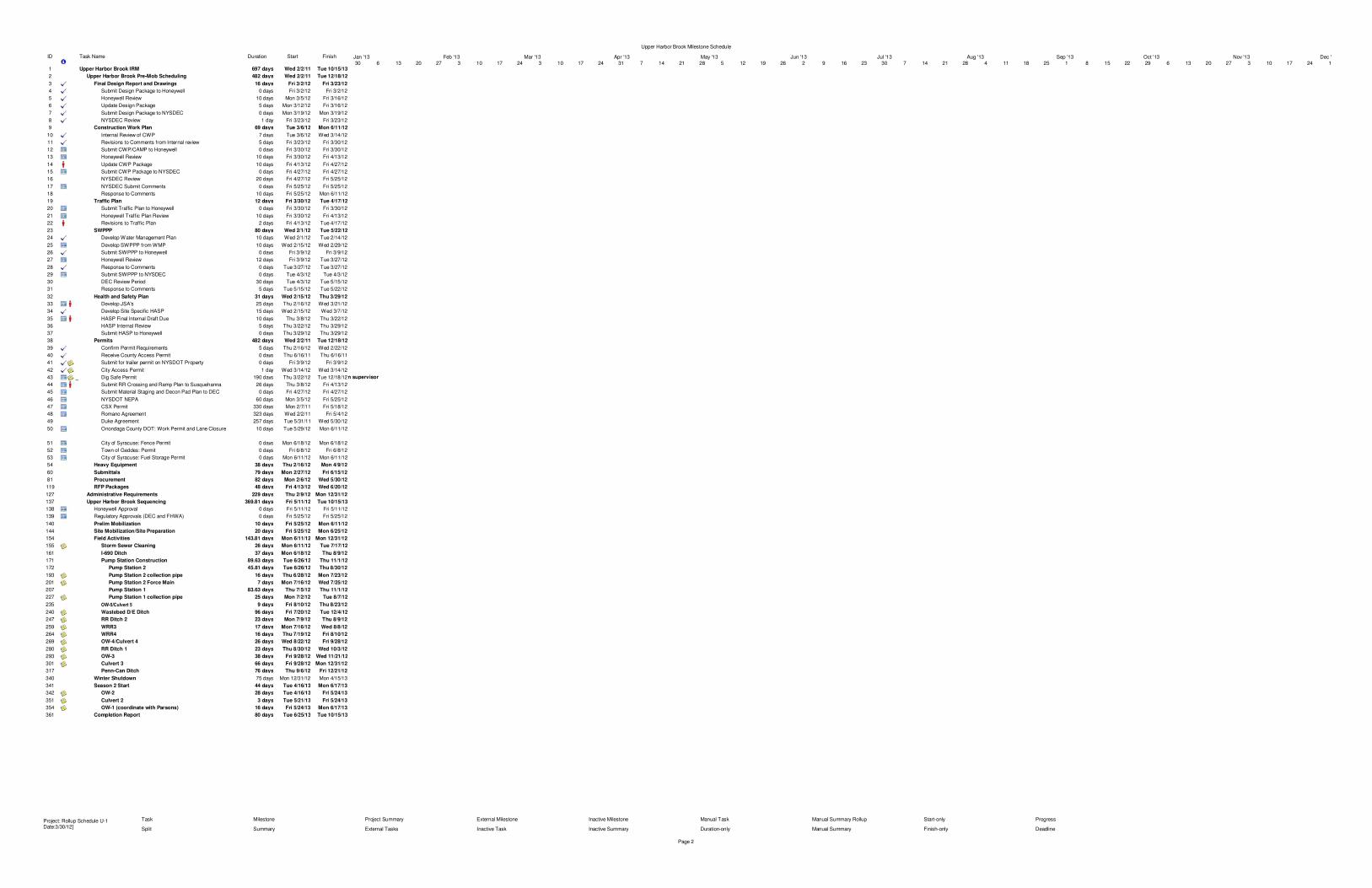
ID Task Name Duration Start Finish
1 Upper Harbor Brook IRM 697 days Wed 2/2/11 Tue 10/15/13
2 Upper Harbor Brook Pre-Mob Scheduling 482 days Wed 2/2/11 Tue 12/18/12
3 Final Design Report and Drawings 16 days Fri 3/2/12 Fri 3/23/12
4 Submit Design Package to Honeywell 0 days Fri 3/2/12 Fri 3/2/12
5 Honeywell Review 10 days Mon 3/5/12 Fri 3/16/12
6 Update Design Package 5 days Mon 3/12/12 Fri 3/16/12
7 Submit Design Package to NYSDEC 0 days Mon 3/19/12 Mon 3/19/12
8 NYSDEC Review 1 day Fri 3/23/12 Fri 3/23/12
9 Construction Work Plan 69 days Tue 3/6/12 Mon 6/11/12
10 Internal Review of CWP 7 days Tue 3/6/12 Wed 3/14/12
11 Revisions to Comments from Internal review 5 days Fri 3/23/12 Fri 3/30/12
12 Submit CWP/CAMP to Honeywell 0 days Fri 3/30/12 Fri 3/30/12
13 Honeywell Review 10 days Fri 3/30/12 Fri 4/13/12
14 Update CWP Package 10 days Fri 4/13/12 Fri 4/27/12
15 Submit CWP Package to NYSDEC 0 days Fri 4/27/12 Fri 4/27/12
16 NYSDEC Review 20 days Fri 4/27/12 Fri 5/25/12
17 NYSDEC Submit Comments 0 days Fri 5/25/12 Fri 5/25/12
18 Response to Comments 10 days Fri 5/25/12 Mon 6/11/12
19 Traffic Plan 12 days Fri 3/30/12 Tue 4/17/12
20 Submit Traffic Plan to Honeywell 0 days Fri 3/30/12 Fri 3/30/12
21 Honeywell Traffic Plan Review 10 days Fri 3/30/12 Fri 4/13/12
22 Revisions to Traffic Plan 2 days Fri 4/13/12 Tue 4/17/12
23 SWPPP 80 days Wed 2/1/12 Tue 5/22/12
24 Develop Water Management Plan 10 days Wed 2/1/12 Tue 2/14/12
25 Develop SWPPP from WMP 10 days Wed 2/15/12 Wed 2/29/12
26 Submit SWPPP to Honeywell 0 days Fri 3/9/12 Fri 3/9/12
27 Honeywell Review 12 days Fri 3/9/12 Tue 3/27/12
28 Response to Comments 0 days Tue 3/27/12 Tue 3/27/12
29 Submit SWPPP to NYSDEC 0 days Tue 4/3/12 Tue 4/3/12
30 DEC Review Period 30 days Tue 4/3/12 Tue 5/15/12
31 Response to Comments 5 days Tue 5/15/12 Tue 5/22/12
32 Health and Safety Plan 31 days Wed 2/15/12 Thu 3/29/12
33 Develop JSA's 25 days Thu 2/16/12 Wed 3/21/12
34 Develop Site Specific HASP 15 days Wed 2/15/12 Wed 3/7/12
35 HASP Final Internal Draft Due 10 days Thu 3/8/12 Thu 3/22/12
36 HASP Internal Review 5 days Thu 3/22/12 Thu 3/29/12
37 Submit HASP to Honeywell 0 days Thu 3/29/12 Thu 3/29/12
38 Permits 482 days Wed 2/2/11 Tue 12/18/12
39 Confirm Permit Requirements 5 days Thu 2/16/12 Wed 2/22/12
40 Receive County Access Permit 0 days Thu 6/16/11 Thu 6/16/11
41 Submit for trailer permit on NYSDOT Property 0 days Fri 3/9/12 Fri 3/9/12
42 City Access Permit 1 day Wed 3/14/12 Wed 3/14/12
43 Dig Safe Permit 190 days Thu 3/22/12 Tue 12/18/12
44 Submit RR Crossing and Ramp Plan to Susquehanna 26 days Thu 3/8/12 Fri 4/13/12
45 Submit Material Staging and Decon Pad Plan to DEC 0 days Fri 4/27/12 Fri 4/27/12
46 NYSDOT NEPA 60 days Mon 3/5/12 Fri 5/25/12
47 CSX Permit 330 days Mon 2/7/11 Fri 5/18/12
48 Romano Agreement 323 days Wed 2/2/11 Fri 5/4/12
49 Duke Agreement 257 days Tue 5/31/11 Wed 5/30/12
50 Onondaga County DOT: Work Permit and Lane Closure 10 days Tue 5/29/12 Mon 6/11/12
51 City of Syracuse: Fence Permit 0 days Mon 6/18/12 Mon 6/18/12
52 Town of Geddes: Permit 0 days Fri 6/8/12 Fri 6/8/12
53 City of Syracuse: Fuel Storage Permit 0 days Mon 6/11/12 Mon 6/11/12
54 Heavy Equipment 38 days Thu 2/16/12 Mon 4/9/12
60 Submittals 79 days Mon 2/27/12 Fri 6/15/12
81 Procurement 82 days Mon 2/6/12 Wed 5/30/12
119 RFP Packages 48 days Fri 4/13/12 Wed 6/20/12
127 Administrative Requirements 229 days Thu 2/9/12 Mon 12/31/12
137 Upper Harbor Brook Sequencing 369.81 days Fri 5/11/12 Tue 10/15/13
138 Honeywell Approval 0 days Fri 5/11/12 Fri 5/11/12
139 Regulatory Approvals (DEC and FHWA) 0 days Fri 5/25/12 Fri 5/25/12
140 Prelim Mobilization 10 days Fri 5/25/12 Mon 6/11/12
144 Site Mobilization/Site Preparation 20 days Fri 5/25/12 Mon 6/25/12
154 Field Activities 143.81 days Mon 6/11/12 Mon 12/31/12
155 Storm Sewer Cleaning 26 days Mon 6/11/12 Tue 7/17/12
161 I-690 Ditch 37 days Mon 6/18/12 Thu 8/9/12
171 Pump Station Construction 89.63 days Tue 6/26/12 Thu 11/1/12
172 Pump Station 2 45.81 days Tue 6/26/12 Thu 8/30/12
193 Pump Station 2 collection pipe 16 days Thu 6/28/12 Mon 7/23/12
201 Pump Station 2 Force Main 7 days Mon 7/16/12 Wed 7/25/12
207 Pump Station 1 83.63 days Thu 7/5/12 Thu 11/1/12
227 Pump Station 1 collection pipe 25 days Mon 7/2/12 Tue 8/7/12
235 OW-5/Culvert 5 9 days Fri 8/10/12 Thu 8/23/12
240 Wastebed D/E Ditch 96 days Fri 7/20/12 Tue 12/4/12
247 RR Ditch 2 23 days Mon 7/9/12 Thu 8/9/12
259 WRR3 17 days Mon 7/16/12 Wed 8/8/12
264 WRR4 16 days Thu 7/19/12 Fri 8/10/12
269 OW-4/Culvert 4 26 days Wed 8/22/12 Fri 9/28/12
280 RR Ditch 1 23 days Thu 8/30/12 Wed 10/3/12
293 OW-3 38 days Fri 9/28/12 Wed 11/21/12
301 Culvert 3 66 days Fri 9/28/12 Mon 12/31/12
317 Penn-Can Ditch 76 days Thu 9/6/12 Fri 12/21/12
340 Winter Shutdown 75 days Mon 12/31/12 Mon 4/15/13
341 Season 2 Start 44 days Tue 4/16/13 Mon 6/17/13
342 OW-2 28 days Tue 4/16/13 Fri 5/24/13
351 Culvert 2 3 days Tue 5/21/13 Fri 5/24/13
354 OW-1 (coordinate with Parsons) 16 days Fri 5/24/13 Mon 6/17/13
361 Completion Report 80 days Tue 6/25/13 Tue 10/15/13
Construction supervisor
30 6 13 20 27 3 10 17 24 3 10 17 24 31 7 14 21 28 5 12 19 26 2 9 16 23 30 7 14 21 28 4 11 18 25 1 8 15 22 29 6 13 20 27 3 10 17 24 1
Jan '13 Feb '13 Mar '13 Apr '13 May '13 Jun '13 Jul '13 Aug '13 Sep '13 Oct '13 Nov '13 Dec '13
Task
Split
Milestone
Summary
Project Summary
External Tasks
External Milestone
Inactive Task
Inactive Milestone
Inactive Summary
Manual Task
Duration-only
Manual Summary Rollup
Manual Summary
Start-only
Finish-only
Progress
Deadline
Upper Harbor Brook Milestone Schedule
Page 2
Project: Rollup Schedule U-1Date:3/30/12]
o
v'v'v'<$>v'<$>!!H<$>~
!!Hi!!H!!H!!H!!H
!!H
!!H!!H!!H

UPPER HARBOR BROOK / CONSTRUCTION WORK PLAN
360° Engineering and Project Delivery Solutions
Appendix B
CAMP

UPPER HARBOR BROOK IRM / COMMUNITY AIR MONITORING PLAN (CAMP)
360° Engineering and Project Delivery Solutions
I:\Honeywell.1163\49142.Upper-Harbor-Br\Docs\Work Plans\CWP\Final To DEC\App B CAMP_081512_DEC Response_Final.Docx
COMMUNITY AIR MONITORING PLAN
OBJECTIVES AND AIR MONITORING APPROACH
The objective of this community air monitoring plan (CAMP) is to describe air monitoring during the Upper Harbor Brook (UHB) Interim Remedial Measure (IRM). UHB IRM field activities are expected to begin in Spring 2012 and possibly continue through Spring 2013, and includes the following ground intrusive work:
I-690 Ditch – Excavate ditch and WL6, install collection piping and cleanouts, LLDPE liner installation and backfill
Pump Stations/Force Mains – Install sheetpile for excavation support, trench excavation, construction water management, install pipe/cleanouts, and backfill
Wastebed DE Ditch – Sediment removal, LLDPE liner installation and backfill
RR Ditch 1, RR Ditch 2, WRR2 and WRR4 – Excavate, remove sediment, and backfill
OW-1, OW-2, OW-3 – Excavate sediment, LLDPE liner installation and backfill
OW-4/Culvert 4 – Flush culvert/excavate sediment, remove limestone liner, install LLDPE liner and backfill
OW-5/Culvert 5 – Remove sediment and contaminated material/flush sediment from culvert
Penn-Can Ditch – Remove sediment, excavate, check/clean/repair/install culvert, and backfill
Surface soil sampling in the project area has detected the presence of volatile compounds including BTEX and naphthalene. As a result, UHB IRM ground intrusive activities may result in release of volatile air emissions and odors. Therefore, perimeter air monitoring will be conducted.
Perimeter air monitoring will evaluate potential air quality impacts from remedial activities at the site from volatile organic compounds (VOCs), dust, and odors. Other UHB IRM field activities that are not ground intrusive including site mobilization/preparation and work areas ancillary activities will not require perimeter air monitoring during their periods of fieldwork. The air monitoring program described herein has been designed using the New York State Department of Health (NYSDOH) Generic Community Air Monitoring Plan (gCAMP) guidance for evaluation of potential airborne contaminant releases as a direct result of investigative and remedial work activities1
COMMUNITY RECEPTORS
.
The project site is bordered to the north and east by Onondaga Lake, to the south by railroad tracks (CSX and Susquehanna Railroads) and to the east and west by commercial/industrial properties. The CSX Railroad and Interstate 690 (I-690) separate the Project site north and south.
Based on review of aerial photographs, the nearest residential receptors to the project site consist of homes approximately 200 feet south of the southwestern side of the site and 1700 feet to the southeast. The New York State Fairgrounds are located approximately one mile west of the westernmost areas of ground intrusive activities. Additional residential receptors are located over one mile north of the Project, on the north shore of Onondaga Lake.
1 Generic Community Air Monitoring Plan, New York State Department of Health, Revision 1, June 2000.
Ei lJBlllEN (; GEIlE
UPPER HARBOR BROOK IRM / COMMUNITY AIR MONITORING PLAN (CAMP)
360° Engineering and Project Delivery Solutions
I:\Honeywell.1163\49142.Upper-Harbor-Br\Docs\Work Plans\CWP\Final To DEC\App B CAMP_081512_DEC Response_Final.Docx
MONITORING LOCATIONS
Air monitoring will be conducted along or within the perimeter boundary lines around the work site shown on Figure 1. The air monitoring perimeter boundary along the north side of the work site follows the Onondaga Lake shoreline. The west perimeter boundary follows access roads north of I-690, then along and just north of the CSX Railroad, and then follows just north of the Penn-Can drainage ditch. The perimeter boundary along the south side of the site is located just north of the CSX Railroad. The perimeter boundary along the east side of the site follows access roads east of the CSX Railroad, along the south side of I-690, across a the west edge of Hiawatha Associates property (right of way access requested), then along a project access road just north of Susquehanna Railroad.
Perimeter air monitoring locations where portable perimeter monitors will be deployed each day, will depend upon the measured wind direction. The portable air monitors may be moved to a different location during the day if the predominant wind direction shifts into a new quadrant or if the work area changes. Site wind conditions will be monitored each day using either a portable on-site weather station or the Honeywell 10-meter weather station located along the east edge of the Semet Ponds.
DUST MONITORING
Dust monitoring will consist of continuous real-time air monitoring of particulate matter less than 10 microns (PM10) upwind and downwind of the work site during daily activities. There will be at least one upwind and one downwind monitoring location. In cases where there are two or more work areas that are spatially separated such that one monitor cannot be place downwind of both, then one or more additional downwind monitors will be operated. One upwind dust monitor will generally be used to determine ambient background dust for all downwind monitors.
Dust measurements at each location will be made using real-time aerosol monitors (ThermoFisher ADR-1500 or ThermoFisher DataRAM 4000). The ADR-1500 and DataRAM 4000 are photometric light-scattering instruments that continuously measure airborne particulate from 1 microgram per cubic meter (µg/m3) to over 100 milligrams per cubic meter (mg/m3) and record the results in time-averaged concentrations.
Dust monitoring work perimeter limits will be based on guidance contained in the NYSDOH gCAMP. Dust levels will be expressed as 15-minute time-averaged concentrations. Work Perimeter Limits and corrective responses will be as follows:
Control Level - If the downwind PM10 level is 100 µg/m3 above the upwind level for a 15-minute period or if airborne dust is observed leaving the site perimeter, then additional dust suppression techniques must be employed. Work may continue with dust suppression techniques provided that downwind PM10 levels do not exceed 150 µg/m3 above the upwind level and provided that no visible dust is migrating from the work area.
Work Perimeter Limit - If, after implementation of dust suppression techniques, downwind PM10 levels are greater than 150 µg/m3 above the upwind level, work must be stopped and a re-evaluation of activities initiated. Work can resume provided that dust suppression measures and other controls are successful in reducing the downwind PM10 concentration to within 150 µg/m3 of the upwind level and in preventing visible off-site dust migration.
Each dust monitor will automatically alert an air monitoring technician (either visual or audible alarm, pager, or text message) to indicate high readings that may lead to potential exceedances of work perimeter limits. The air monitoring technician will then alert the site construction manager.
VOC MONITORING
VOC monitoring will consist of continuous real-time air monitoring of total VOCs (TVOCs) upwind and downwind of the work site during daily activities. There will be at least one upwind and one downwind monitoring location. In cases where two or more work areas are spatially separated such that one monitor cannot be downwind of both, then one or more additional downwind monitors will be operated. One upwind TVOC monitor will be used to determine ambient background TVOCs for all downwind monitors.
Ei lJBlllEN (; GEIlE

UPPER HARBOR BROOK IRM / COMMUNITY AIR MONITORING PLAN (CAMP)
360° Engineering and Project Delivery Solutions
I:\Honeywell.1163\49142.Upper-Harbor-Br\Docs\Work Plans\CWP\Final To DEC\App B CAMP_081512_DEC Response_Final.Docx
Measurements at each location will be made using real-time TVOC analyzers (RAE Systems MiniRae 3000, or equivalent). The MiniRae 3000 is a UV-light photo-ionizing detector (PID) that continuously measures TVOCs from 0.1 to 15,000 parts per million (ppm), and records the results in time-averaged concentrations.
TVOC work perimeter limits will be based on guidance contained in the NYSDOH gCAMP. Additional lower level criteria have also been incorporated to provide corrective responses prior to reaching the Project CAMP TVOC guidance limits. TVOC results will be expressed as 15-minute time-averaged concentrations. Work perimeter criteria and corrective responses will be as follows:
Investigation Level - If the downwind TVOC level is 2 ppm above the upwind (background) level for a 15-minute period, then the emission sources will be investigated and evaluated.
Control Level - If the downwind TVOC level is 3 ppm above the background level for a 15-minute period, controls or countermeasures will be employed on the operation activity(ies) causing the concentration increase. Controls/countermeasures will be reviewed to determine best possible solution. Work may continue with controls and countermeasures provided that downwind VOC levels do not exceed 3 ppm above the background level.
Work Perimeter Limit - If the downwind TVOC level exceeds 5 ppm above the background for the 15-minute period, work activities will be temporarily halted or restricted and monitoring continued. If the TVOC level readily decreases (per instantaneous readings) below 5 ppm (above background), work activities can resume with continued monitoring. If the downwind TVOC level persists in excess of 5 ppm (above background), work activities will be halted, the source of vapors identified, controls/countermeasures taken to abate emissions, and monitoring continued. After these steps, work activities can resume provided that the TVOC at the downwind perimeter site is below 5 ppm (above background) for the 15-minute average.
Background is identified by an upwind perimeter sample for each 15-minute period. Each PID will automatically alert the air monitoring technician (either visual or audible alarm, pager, or text message) to indicate high readings that may lead to potential exceedances of action criteria. The air monitoring technician will then alert the site construction manager.
ODOR MONITORING
Perimeter odor monitoring will consist of qualitative on-site odor observations downwind of daily work activities. Observations will be made at or within the site perimeter. There are no applicable Federal, State or local regulations that provide guidance on the odor levels that result in a significant impact on the public. However, if odors levels at the site are observed to increase noticeably due to site activities, then odor levels will be quantified using a real-time Nasal Ranger portable field olfactometer in terms of “odor units” (OU), and then also checked at a location upwind of site activities. If odors due to project activities are measured at >7 OU over a 15 minute period at the nearest downwind residence, or if community complaints are received that can be attributed to the site activities, then controls and/or countermeasures will be implemented to control odors.
QUALITY CONTROL AND QUALITY ASSURANCE
Zero and span calibration checks, and routine maintenance of real-time analyzers will be conducted at the beginning of each day following applicable manufacturer’s calibration guidelines. Field checks of the olfactometer will consist of daily checks of gaskets, valves, and odor filter cartridge performance. Odor filter cartridges will be replaced as-required based on use. Records of daily field activities, calibrations and instrument field checks will be documented onto pre-printed field forms and/or in the project site log.
DATA MANAGEMENT AND REPORTING
Data will be manually or automatically downloaded to a computer each day for review and validation. Background levels, any exceedance of action levels or compliance criteria, and a summary of response actions taken will be recorded in daily field logs and/or daily summary field forms. At the conclusion of the air monitoring program, final results will be presented in a summary report that will include:
Ei lJBlllEN (; GEIlE

UPPER HARBOR BROOK IRM / COMMUNITY AIR MONITORING PLAN (CAMP)
360° Engineering and Project Delivery Solutions
I:\Honeywell.1163\49142.Upper-Harbor-Br\Docs\Work Plans\CWP\Final To DEC\App B CAMP_081512_DEC Response_Final.Docx
air monitoring methodologies
tabulated summaries of results
assessment of air quality levels versus action criteria, and
assessment of odor impacts on downwind residential receptors.
Ei lJBlllEN (; GEIlE
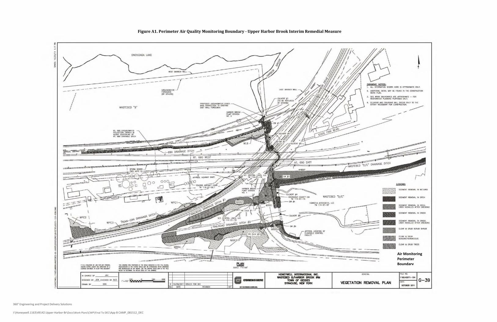
360° Engineering and Project Delivery Solutions
I:\Honeywell.1163\49142.Upper-Harbor-Br\Docs\Work Plans\CWP\Final To DEC\App B CAMP_081512_DEC
Figure A1. Perimeter Air Quality Monitoring Boundary - Upper Harbor Brook Interim Remedial Measure
Air Monitoring Perimeter Boundary
.r--------------------------------------------------------------,
DRAWlttC !jam;.1...... 0Nf1:fIlM1lCf< __ IS _110.....1£ ONlT.
~ 0Ef... "" ill: rOUNO .. "'I: CONSTIIUCTION
-~.SlIt oo:lAI< !IOiJIOOIII[S ... _'rt _ n)O
ll£STOMTlQ. l'l.N<...C ""PlPDSa C....y,
C\.EIO!ItC" ....0 _ "u. OOCUI 0.... to J>€000" 1£CE5SNlr raft COHSI1lUCTlOH.
'-.----~--
-----
or.... 0R<II.NIlWA''''e~ 1100:>< ISOLONC Cl:NTO'Ul[ 01or._ ........... """"
WASTEBED "8"
---
~~Q~~~1
I
I
/---
ONONDAGA lAKE
I,
---=
!