Upgraded Grounding and Bonding Systems Prevent … are now double-holed copper, removed, treated and...
4
Costly damage and downtime are real problems for broadcast facilities operating in lightning prone locations. Fortunately, these problems can often be prevented and without expensive solutions. MARC Radio Gainesville is an example. It recently acquired three new FM stations that share a transmission facility in Trenton, Florida: WDVH, WPLL and WHHZ. Frank Garcia, the group’s former chief information officer, recognized lightning-related problems at all three of the stations. COPPER ELECTRICAL APPLICATION - POWER QUALITY | WWW.COPPER.ORG Upgraded Grounding and Bonding Systems Prevent Costly Disasters for Florida Radio Group To resolve the problems, Garcia called John West Sr., principal of Power & Systems Innovations of Tampa, Florida, who has had great success remedying similar difficulties at other properties in the MARC chain. Cost-efficiency is important Upon initial inspection, the improper grounding and bonding at the transmission site were found to be the major cause of the problems (Figures 1 and 2). Photo is of the WTMG tower.
Transcript of Upgraded Grounding and Bonding Systems Prevent … are now double-holed copper, removed, treated and...
Costly damage and downtime are real problems for broadcast facilities operating in lightning prone locations. Fortunately, these problems can often be prevented and without expensive solutions.
MARC Radio Gainesville is an example. It recently acquired three new FM stations that share a transmission facility in Trenton, Florida: WDVH, WPLL and WHHZ. Frank Garcia, the group’s former chief information officer, recognized lightning-related problems at all three of the stations.
COPPER ELECTRICAL APPLICATION - POWER QUALITY | WWW.COPPER.ORG
Upgraded Grounding and Bonding Systems Prevent Costly Disasters for Florida Radio Group
To resolve the problems, Garcia called John West Sr., principal of Power & Systems Innovations of Tampa, Florida, who has had great success remedying similar difficulties at other properties in the MARC chain.
Cost-efficiency is importantUpon initial inspection, the improper grounding and bonding at the transmission site were found to be the major cause of the problems (Figures 1 and 2).
Photo is of the WTMG tower.
COPPER ELECTRICAL APPLICATION - POWER QUALITY | WWW.COPPER.ORG
West’s approach is to install a grounding system in the most cost-effective manner based on site conditions. “Take advantage of the site conditions,” West said. “Do it right, and do it as cheaply as you can.”
To accomplish this, he looks to install the ground rods where the soil can be kept wet such as areas where water is coming out of the condensate line from the air conditioner unit; where there is a downspout off the building; or something as simple as a retention pond near the facility so that during the rainy season that soil is always moist. He also suggests putting rods in a planting area that has irrigation. These approaches help minimize costs to the owner and the results are excellent.
In Trenton, the transmitter facilities are located on what is basically a sand hill. Therefore, ground rods needed to be quite deep. At the service entrance, West drilled an 80-foot-deep ground rod that is tied to two other 80-foot rods, starting 80 feet away and 80 feet apart (Figure 3). Together, they provide less than a 5-ohm ground.
The ground system is tied to the waveguide bridge (Figure 4), the facility’s electrical system, the bonding bar (shown in Figure 6) and a halo ground with 4/0 stranded copper.
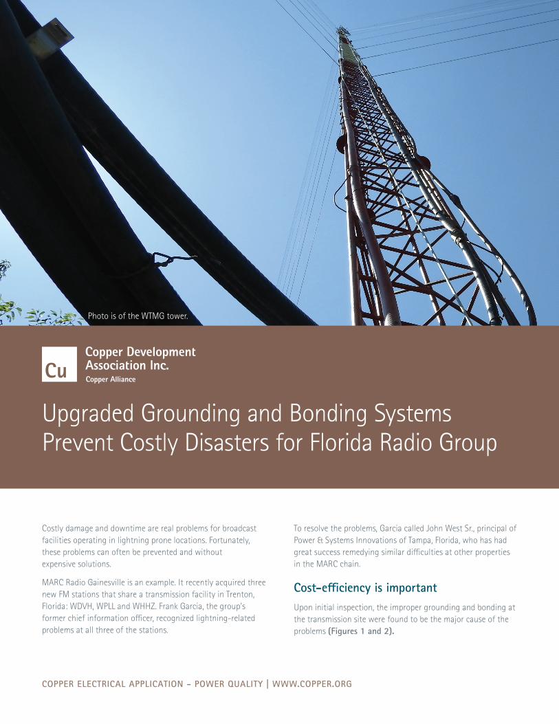
FIGURE 1.
FIGURE 2.FIGURE 3.
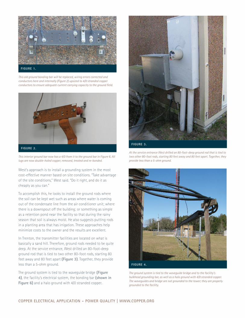
FIGURE 4.
This old ground bonding bar will be replaced, wiring errors corrected and conductors here and internally (Figure 2) upsized to 4/0 stranded copper conductors to ensure adequate current carrying capacity to the ground field.
This interior ground bar now has a 4/0 from it to the ground bar in Figure 6. All lugs are now double-holed copper, removed, treated and re-bonded.
At the service entrance West drilled an 80-foot-deep ground rod that is tied to two other 80-foot rods, starting 80 feet away and 80 feet apart. Together, they provide less than a 5-ohm ground.
The ground system is tied to the waveguide bridge and to the facility’s bulkhead grounding bar, as well as a halo ground with 4/0 stranded copper. The waveguides and bridge are not grounded to the tower; they are properly grounded to the facility.
COPPER ELECTRICAL APPLICATION - POWER QUALITY | WWW.COPPER.ORG
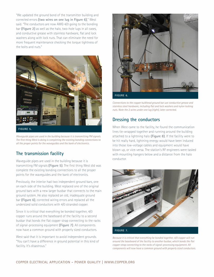
“We updated the ground bond of the transmitter building and corrected errors (two wires on one lug in Figure 6),” West said. “The conductors are now AWG 4/0 going to the bonding bar (Figure 2) as well as the halo, two-hole lugs in all cases, and conductive grease with stainless hardware, flat and lock washers along with lock nuts. That can eliminate the need for more frequent maintenance checking the torque tightness of the bolts and nuts.”
The transmission facilityWaveguide pipes are used in the building because it is transmitting FM signals (Figure 5). The first thing West did was complete the existing bonding connections to all the proper points for the waveguides and the bank of electronics.
Previously, the interior had two independent ground bars, one on each side of the building. West replaced one of the original ground bars with a new larger busbar that connects to the main ground system. He also replaced an old, inadequate ground bar (Figure 6), corrected wiring errors and replaced all the undersized solid conductors with 4/0 stranded copper.
Since it is critical that everything be bonded together, 4/0 copper runs around the baseboard of the facility to a second busbar that bonds the flat copper strap connecting to the racks of signal-processing equipment (Figure 7). All components now have a common ground with properly sized conductors.
West said that it is important to avoid independent grounds. “You can’t have a difference in ground potential in this kind of facility. It’s disastrous.”
FIGURE 5.
FIGURE 6.
FIGURE 7.
Waveguide pipes are used in the building because it is transmitting FM signals. The first thing West is doing is completing the existing bonding connections to all the proper points for the waveguides and the bank of electronics.
Connections to the copper bulkhead ground bar use conductive grease and stainless steel hardware, including flat and lock washers and nylon locking nuts. Note the 2 wires under one lug (right), later corrected.
Because it is critical that everything be bonded together, 4/0 copper will run around the baseboard of the facility to another busbar, which bonds the flat copper strap connecting to the racks of signal-processing equipment. All components will now have a common ground with properly sized conductors.
Dressing the conductorsWhen West came to the facility, he found the communication lines tie-wrapped together and running around the building attached to a lightning halo (Figure 8). If the facility were to be hit really hard, lightning energy would have been induced into those low-voltage cables and equipment would have blown up, or vice-versa. The station’s RF engineers were tasked with mounting hangers below and a distance from the halo conductor.
COPPER ELECTRICAL APPLICATION - POWER QUALITY | WWW.COPPER.ORG
copper.orgA6190 XX/17
Outside Next to the transmission facility is a bridge that takes the waveguides to the antenna tower (Figure 4). They are not grounded to the tower; they are properly grounded to the facility. Because the waveguides strictly service the antennas, it does not present a difference-in-ground-potential situation.
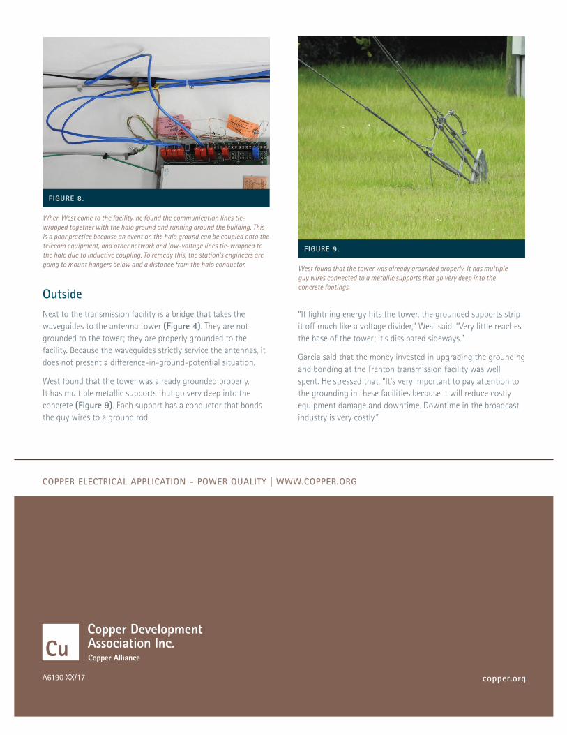
West found that the tower was already grounded properly. It has multiple metallic supports that go very deep into the concrete (Figure 9). Each support has a conductor that bonds the guy wires to a ground rod.
FIGURE 8.
FIGURE 9.
When West came to the facility, he found the communication lines tie-wrapped together with the halo ground and running around the building. This is a poor practice because an event on the halo ground can be coupled onto the telecom equipment, and other network and low-voltage lines tie-wrapped to the halo due to inductive coupling. To remedy this, the station’s engineers are going to mount hangers below and a distance from the halo conductor. West found that the tower was already grounded properly. It has multiple
guy wires connected to a metallic supports that go very deep into the concrete footings.
“If lightning energy hits the tower, the grounded supports strip it off much like a voltage divider,” West said. “Very little reaches the base of the tower; it’s dissipated sideways.”
Garcia said that the money invested in upgrading the grounding and bonding at the Trenton transmission facility was well spent. He stressed that, “It’s very important to pay attention to the grounding in these facilities because it will reduce costly equipment damage and downtime. Downtime in the broadcast industry is very costly.”