Upflow/ Horizontal Downflow/Horizontal Condensing, Direct ... · Upflow/ Horizontal...
18
Upflow/ Horizontal Downflow/Horizontal Condensing, Direct Vent Gas-Fired Furnace PUB. NO. 22-1836-07 XR 95 TUH1B040A9241A, TUH1B060A9361A, TUH1B080A9421A, TUH1C080A9601A, TUH1C100A9481A, TUH1D100A9601A, TUH1D120A9601A, TDH1B040A9241A, TDH1B065A9421A, TDH1C085A9481A, TDH1D110A9601A Single-Stage Fan Assisted Combustion System *DH1 DOWNFLOW DOWNFLOW/HORIZONTAL *UH1 UPFLOW *UH1 UPFLOW/HORIZONTAL *DH1
Transcript of Upflow/ Horizontal Downflow/Horizontal Condensing, Direct ... · Upflow/ Horizontal...
Upflow/ HorizontalDownflow/HorizontalCondensing, Direct VentGas-Fired Furnace
PUB. NO. 22-1836-07
XR 95TUH1B040A9241A, TUH1B060A9361A,TUH1B080A9421A, TUH1C080A9601A,TUH1C100A9481A, TUH1D100A9601A,TUH1D120A9601A, TDH1B040A9241A,TDH1B065A9421A, TDH1C085A9481A,TDH1D110A9601A
Single-Stage Fan AssistedCombustion System
*DH1DOWNFLOW
DOWNFLOW/HORIZONTAL
*UH1UPFLOW
*UH1UPFLOW/HORIZONTAL
*DH1
© 2011 Trane All Rights Reserved 2 22-1836-07
GeneralFeatures
NATURAL GAS MODELSCentral Heating furnace designs arecertified to ANSI Z21.47 / CSA 2.3 forboth natural and L.P. gas. Limit settingand rating data were established andapproved under standard rating condi-tions using American National StandardsInstitute standards.
SAFE OPERATIONThe Integrated System Control has solidstate devices, which continuously monitorfor presence of flame, when the system isin the heating mode of operation. Dualsolenoid combination gas valve andregulator provide extra safety.
QUICK HEATINGDurable, cycle tested, heavy gaugealuminized steel heat exchangerquickly transfers heat to provide warmconditioned air to the structure. Lowenergy power vent blower, to increaseefficiency and provide a positive dis-charge of gas fumes to the outside.
BURNERSMultiport Inshot burners will give years ofquiet and efficient service. All modelscan be converted to L.P. gas withoutchanging burners.
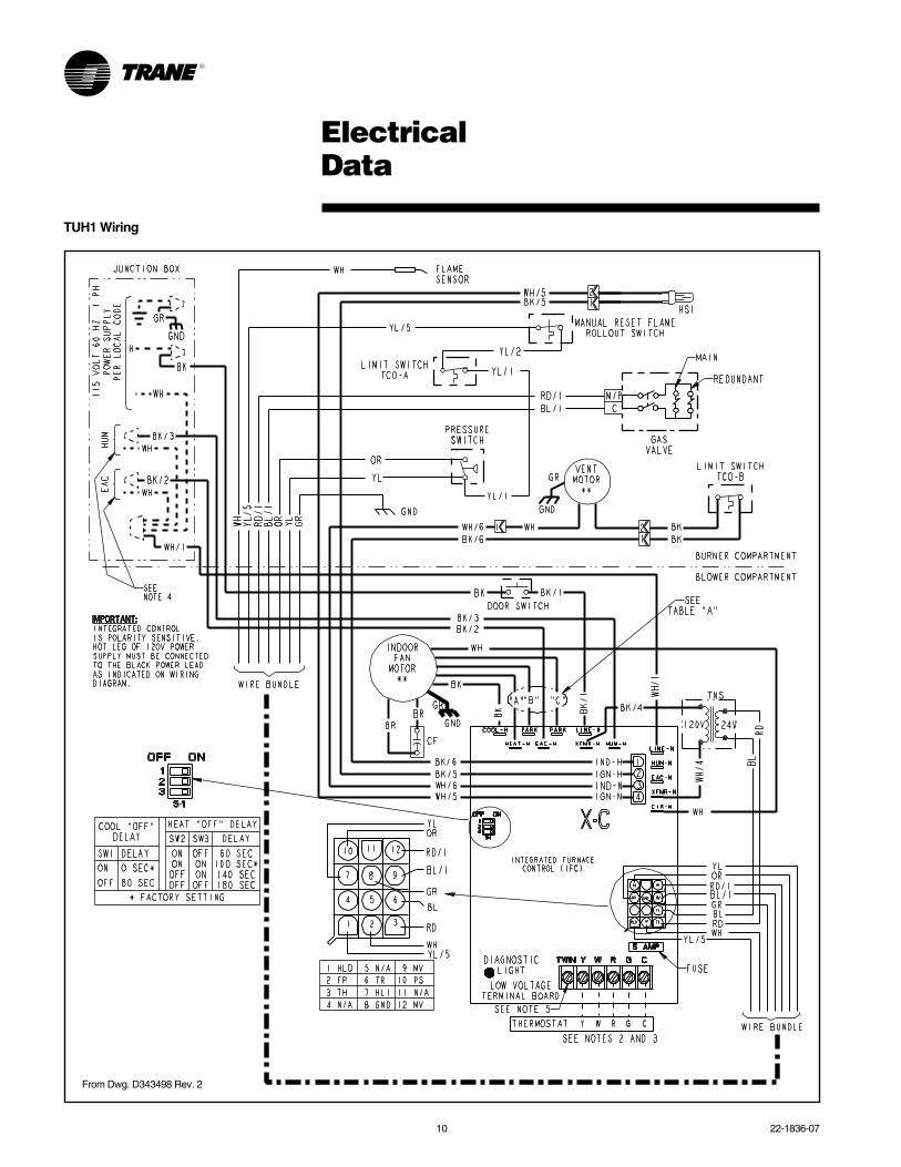
INTEGRATED SYSTEM CONTROLExclusively designed operational pro-gram provides total control of furnacelimit sensors, blowers, gas valve, flamecontrol and includes self diagnostics forease of service. Also contains connec-tion points for E.A.C./humidifier.
AIR DELIVERYThe four speed, direct drive blowermotor, has sufficient airflow for mostheating and cooling requirements, willswitch from heating to cooling speeds ondemand from room thermostat. Theblower door safety switch will prevent orterminate furnace operation when theblower door is removed.
STYLINGHeavy gauge steel and “wrap-around”cabinet construction is used in thecabinet with baked-on enamel finish forstrength and beauty. The heat ex-changer section of the cabinet is com-pletely lined with foil faced fiberglassinsulation. This results in quiet andefficient operation due to the excellentacoustical and insulating qualities offiberglass. Built-in bottom pan andalternate bottom, left or right side returnair connection provision.
FEATURES ANDGENERAL OPERATIONThe XR 95 High Efficiency Gas Furnacesemploy a Silicon Nitride Hot SurfaceIgnition system, which eliminates thewaste of a constant burning pilot. Theintegrated system control lights the mainburners upon a demand for heat from theroom thermostat. Complete front serviceaccess.
a. Low energy power venter
b. Vent proving pressure switch.
Featuresand Benefits
XR 95 Standard Equipment• Power supply 115/1/60
• Convertible to horizontal
• Type 29-4C™ stainless steel second-ary heat exchanger
• Inner blower doors
• Direct drive, 4-speed motors
• Silicon Nitride igniter with adaptiveheat up
• Accessory hook-up capability –Hum and EAC
• Quiet induced draft blower
• Blower door safety switch
• Dual solenoid combination gas valve ®ulator
• PVC venting – 1 or 2 pipe vent option
• Left/right gas connection
• Selectable cooling fan off delayeliminates need for BAY24X045 timedelay relay
• Single wire twinning
• Integrated solid state control with self-diagnostics
• 24 volt fuse
• Manual reset burner box limit
• Optional extended warranties
22-1836-07 3
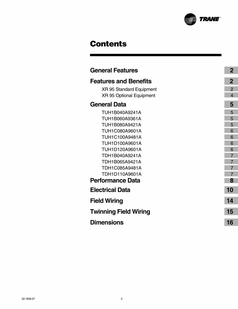
Contents
General Features 2
Features and Benefits 2XR 95 Standard Equipment 2XR 95 Optional Equipment 4
General Data 5TUH1B040A9241A 5TUH1B060A9361A 5TUH1B080A9421A 5TUH1C080A9601A 6TUH1C100A9481A 6TUH1D100A9601A 6TUH1D120A9601A 6TDH1B040A9241A 7TDH1B065A9421A 7TDH1C085A9481A 7TDH1D110A9601A 7
Performance Data 8
Electrical Data 10
Field Wiring 14
Twinning Field Wiring 15
Dimensions 16
4 22-1836-07
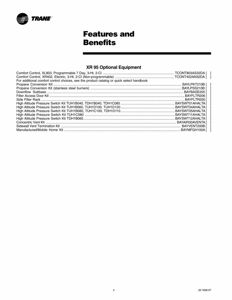
Features andBenefits
XR 95 Optional EquipmentComfort Control, XL803, Programmable 7 Day, 3-Ht, 2-Cl ........................................................................... TCONT803AS32DA [ ]Comfort Control, XR402, Electric, 3-Ht, 2-Cl (Non-programmable) .............................................................. TCONT402AN32DA [ ]For additional comfort control choices, see the product catalog or quick select handbookPropane Conversion Kit ....................................................................................................................................... BAYLPKT210B [ ]Propane Conversion Kit (stainless steel burners) ................................................................................................ BAYLPSS210B [ ]Downflow Subbase ................................................................................................................................................ BAYBASE205 [ ]Filter Access Door Kit .............................................................................................................................................. BAYFLTR206 [ ]Side Filter Rack ....................................................................................................................................................... BAYFLTR200 [ ]High Altitude Pressure Switch Kit TUH1B040, TDH1B040, TDH1C085 .........................................................BAYSWT01AHALTA [ ]High Altitude Pressure Switch Kit TUH1B060, TUH1D100, TUH1D120 .........................................................BAYSWT04AHALTA [ ]High Altitude Pressure Switch Kit TUH1B080, TUH1C100, TDH1D110 .........................................................BAYSWT05AHALTA [ ]High Altitude Pressure Switch Kit TUH1C080 ...............................................................................................BAYSWT11AHALTA [ ]High Altitude Pressure Switch Kit TDH1B065 ................................................................................................BAYSWT12AHALTA [ ]Concentric Vent Kit ......................................................................................................................................... BAYAIR30AVENTA [ ]Sidewall Vent Termination Kit .............................................................................................................................. BAYVENT200B [ ]Manufactured/Mobile Home Kit ...........................................................................................................................BAYMFGH100A [ ]
22-1836-07 5
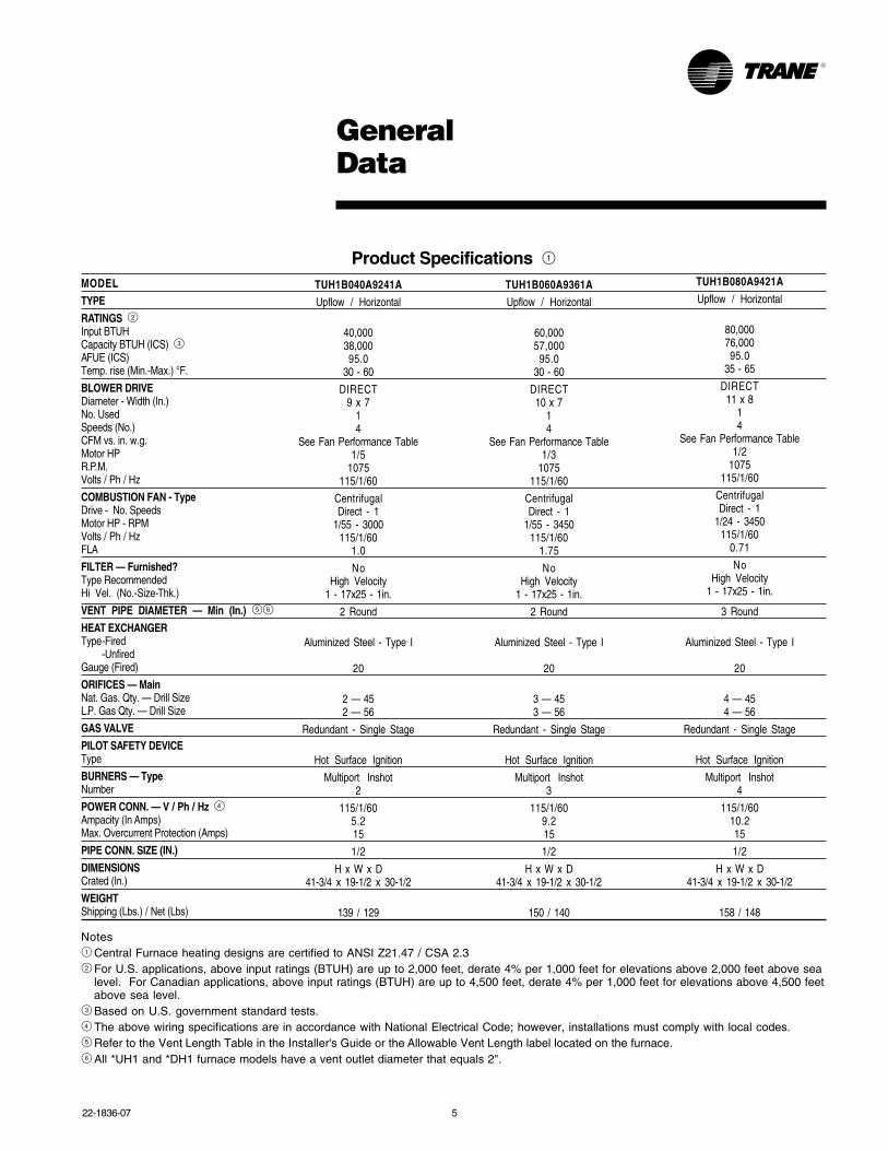
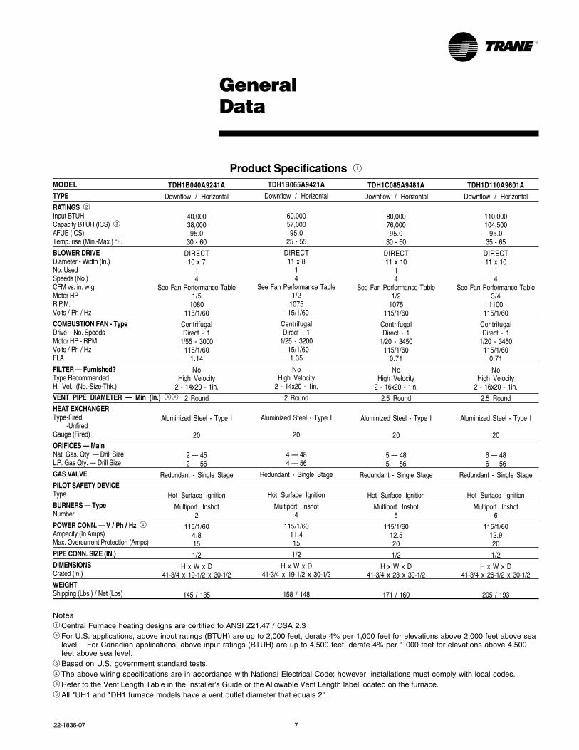
Product Specifications 1MODEL
TYPE
RATINGS 2Input BTUHCapacity BTUH (ICS) 3AFUE (ICS)Temp. rise (Min.-Max.) °F.
BLOWER DRIVEDiameter - Width (In.)No. UsedSpeeds (No.)CFM vs. in. w.g.Motor HPR.P.M.Volts / Ph / Hz
COMBUSTION FAN - TypeDrive - No. SpeedsMotor HP - RPMVolts / Ph / HzFLA
FILTER — Furnished?Type RecommendedHi Vel. (No.-Size-Thk.)
VENT PIPE DIAMETER — Min (In.) 56
HEAT EXCHANGERType-Fired
-UnfiredGauge (Fired)
ORIFICES — MainNat. Gas. Qty. — Drill SizeL.P. Gas Qty. — Drill Size
GAS VALVE
PILOT SAFETY DEVICEType
BURNERS — TypeNumber
POWER CONN. — V / Ph / Hz 4Ampacity (In Amps)Max. Overcurrent Protection (Amps)
PIPE CONN. SIZE (IN.)
DIMENSIONSCrated (In.)
WEIGHTShipping (Lbs.) / Net (Lbs)
GeneralData
TUH1B040A9241A
Upflow / Horizontal
40,00038,00095.0
30 - 60
DIRECT9 x 7
14
See Fan Performance Table1/5
1075115/1/60
CentrifugalDirect - 1
1/55 - 3000115/1/60
1.0
NoHigh Velocity
1 - 17x25 - 1in.
2 Round
Aluminized Steel - Type I
20
2 — 452 — 56
Redundant - Single Stage
Hot Surface Ignition
Multiport Inshot2
115/1/605.215
1/2
H x W x D41-3/4 x 19-1/2 x 30-1/2
139 / 129
TUH1B060A9361A
Upflow / Horizontal
60,00057,000
95.030 - 60
DIRECT10 x 7
14
See Fan Performance Table1/3
1075115/1/60
CentrifugalDirect - 1
1/55 - 3450115/1/60
1.75
NoHigh Velocity
1 - 17x25 - 1in.
2 Round
Aluminized Steel - Type I
20
3 — 453 — 56
Redundant - Single Stage
Hot Surface Ignition
Multiport Inshot3
115/1/609.215
1/2
H x W x D41-3/4 x 19-1/2 x 30-1/2
150 / 140
Notes1 Central Furnace heating designs are certified to ANSI Z21.47 / CSA 2.32 For U.S. applications, above input ratings (BTUH) are up to 2,000 feet, derate 4% per 1,000 feet for elevations above 2,000 feet above sea
level. For Canadian applications, above input ratings (BTUH) are up to 4,500 feet, derate 4% per 1,000 feet for elevations above 4,500 feetabove sea level.
3 Based on U.S. government standard tests.4 The above wiring specifications are in accordance with National Electrical Code; however, installations must comply with local codes.5 Refer to the Vent Length Table in the Installer's Guide or the Allowable Vent Length label located on the furnace.6 All *UH1 and *DH1 furnace models have a vent outlet diameter that equals 2".
TUH1B080A9421A
Upflow / Horizontal
80,00076,00095.0
35 - 65
DIRECT11 x 8
14
See Fan Performance Table1/2
1075115/1/60
CentrifugalDirect - 1
1/24 - 3450115/1/60
0.71
NoHigh Velocity
1 - 17x25 - 1in.
3 Round
Aluminized Steel - Type I
20
4 — 454 — 56
Redundant - Single Stage
Hot Surface Ignition
Multiport Inshot4
115/1/6010.215
1/2
H x W x D41-3/4 x 19-1/2 x 30-1/2
158 / 148
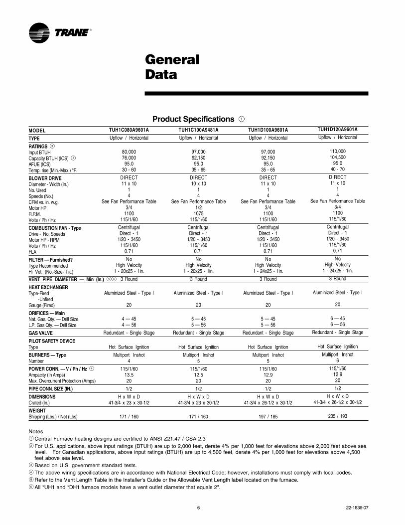
6 22-1836-07
TUH1C100A9481A
Upflow / Horizontal
97,00092,15095.0
35 - 65
DIRECT10 x 10
14
See Fan Performance Table1/2
1075115/1/60
CentrifugalDirect - 1
1/20 - 3450115/1/60
0.71
NoHigh Velocity
1 - 20x25 - 1in.
3 Round
Aluminized Steel - Type I
20
5 — 455 — 56
Redundant - Single Stage
Hot Surface Ignition
Multiport Inshot5
115/1/6012.520
1/2
H x W x D41-3/4 x 23 x 30-1/2
171 / 160
TUH1D120A9601A
Upflow / Horizontal
110,000104,500
95.040 - 70
DIRECT11 x 10
14
See Fan Performance Table3/4
1100115/1/60
CentrifugalDirect - 1
1/20 - 3450115/1/60
0.71
NoHigh Velocity
1 - 24x25 - 1in.
3 Round
Aluminized Steel - Type I
20
6 — 456 — 56
Redundant - Single Stage
Hot Surface Ignition
Multiport Inshot6
115/1/6012.920
1/2
H x W x D41-3/4 x 26-1/2 x 30-1/2
205 / 193
TUH1D100A9601A
Upflow / Horizontal
97,00092,15095.0
35 - 65
DIRECT11 x 10
14
See Fan Performance Table3/4
1100115/1/60
CentrifugalDirect - 1
1/20 - 3450115/1/60
0.71
NoHigh Velocity
1 - 24x25 - 1in.
3 Round
Aluminized Steel - Type I
20
5 — 455 — 56
Redundant - Single Stage
Hot Surface Ignition
Multiport Inshot5
115/1/6012.920
1/2
H x W x D41-3/4 x 26-1/2 x 30-1/2
197 / 185
Product Specifications 1MODEL
TYPE
RATINGS 2Input BTUHCapacity BTUH (ICS) 3AFUE (ICS)Temp. rise (Min.-Max.) °F.
BLOWER DRIVEDiameter - Width (In.)No. UsedSpeeds (No.)CFM vs. in. w.g.Motor HPR.P.M.Volts / Ph / Hz
COMBUSTION FAN - TypeDrive - No. SpeedsMotor HP - RPMVolts / Ph / HzFLA
FILTER — Furnished?Type RecommendedHi Vel. (No.-Size-Thk.)VENT PIPE DIAMETER — Min (In.) 56
HEAT EXCHANGERType-Fired
-UnfiredGauge (Fired)
ORIFICES — MainNat. Gas. Qty. — Drill SizeL.P. Gas Qty. — Drill Size
GAS VALVE
PILOT SAFETY DEVICEType
BURNERS — TypeNumber
POWER CONN. — V / Ph / Hz 4Ampacity (In Amps)Max. Overcurrent Protection (Amps)
PIPE CONN. SIZE (IN.)
DIMENSIONSCrated (In.)
WEIGHTShipping (Lbs.) / Net (Lbs)
Notes1 Central Furnace heating designs are certified to ANSI Z21.47 / CSA 2.32 For U.S. applications, above input ratings (BTUH) are up to 2,000 feet, derate 4% per 1,000 feet for elevations above 2,000 feet above sea
level. For Canadian applications, above input ratings (BTUH) are up to 4,500 feet, derate 4% per 1,000 feet for elevations above 4,500feet above sea level.
3 Based on U.S. government standard tests.4 The above wiring specifications are in accordance with National Electrical Code; however, installations must comply with local codes.5 Refer to the Vent Length Table in the Installer's Guide or the Allowable Vent Length label located on the furnace.6 All *UH1 and *DH1 furnace models have a vent outlet diameter that equals 2".
GeneralData
TUH1C080A9601A
Upflow / Horizontal
80,00076,000
95.030 - 60
DIRECT11 x 10
14
See Fan Performance Table3/4
1100115/1/60
CentrifugalDirect - 1
1/20 - 3450115/1/60
0.71
NoHigh Velocity
1 - 20x25 - 1in.
3 Round
Aluminized Steel - Type I
20
4 — 454 — 56
Redundant - Single Stage
Hot Surface Ignition
Multiport Inshot4
115/1/6013.520
1/2
H x W x D41-3/4 x 23 x 30-1/2
171 / 160
22-1836-07 7
Notes1 Central Furnace heating designs are certified to ANSI Z21.47 / CSA 2.32 For U.S. applications, above input ratings (BTUH) are up to 2,000 feet, derate 4% per 1,000 feet for elevations above 2,000 feet above sea
level. For Canadian applications, above input ratings (BTUH) are up to 4,500 feet, derate 4% per 1,000 feet for elevations above 4,500feet above sea level.
3 Based on U.S. government standard tests.4 The above wiring specifications are in accordance with National Electrical Code; however, installations must comply with local codes.5 Refer to the Vent Length Table in the Installer's Guide or the Allowable Vent Length label located on the furnace.6 All *UH1 and *DH1 furnace models have a vent outlet diameter that equals 2".
Product Specifications 1MODEL
TYPE
RATINGS 2Input BTUHCapacity BTUH (ICS) 3AFUE (ICS)Temp. rise (Min.-Max.) °F.
BLOWER DRIVEDiameter - Width (In.)No. UsedSpeeds (No.)CFM vs. in. w.g.Motor HPR.P.M.Volts / Ph / Hz
COMBUSTION FAN - TypeDrive - No. SpeedsMotor HP - RPMVolts / Ph / HzFLA
FILTER — Furnished?Type RecommendedHi Vel. (No.-Size-Thk.)VENT PIPE DIAMETER — Min (In.) 56
HEAT EXCHANGERType-Fired
-UnfiredGauge (Fired)
ORIFICES — MainNat. Gas. Qty. — Drill SizeL.P. Gas Qty. — Drill Size
GAS VALVE
PILOT SAFETY DEVICEType
BURNERS — TypeNumber
POWER CONN. — V / Ph / Hz 4Ampacity (In Amps)Max. Overcurrent Protection (Amps)
PIPE CONN. SIZE (IN.)
DIMENSIONSCrated (In.)
WEIGHTShipping (Lbs.) / Net (Lbs)
TDH1B040A9241A
Downflow / Horizontal
40,00038,00095.0
30 - 60
DIRECT10 x 7
14
See Fan Performance Table1/5
1080115/1/60
CentrifugalDirect - 1
1/55 - 3000115/1/60
1.14
NoHigh Velocity
2 - 14x20 - 1in.
2 Round
Aluminized Steel - Type I
20
2 — 452 — 56
Redundant - Single Stage
Hot Surface Ignition
Multiport Inshot2
115/1/604.815
1/2
H x W x D41-3/4 x 19-1/2 x 30-1/2
145 / 135
TDH1B065A9421A
Downflow / Horizontal
60,00057,00095.0
25 - 55
DIRECT11 x 8
14
See Fan Performance Table1/2
1075115/1/60
CentrifugalDirect - 1
1/25 - 3200115/1/60
1.35
NoHigh Velocity
2 - 14x20 - 1in.
2 Round
Aluminized Steel - Type I
20
4 — 484 — 56
Redundant - Single Stage
Hot Surface Ignition
Multiport Inshot4
115/1/6011.415
1/2
H x W x D41-3/4 x 19-1/2 x 30-1/2
158 / 148
TDH1C085A9481A
Downflow / Horizontal
80,00076,00095.0
30 - 60
DIRECT11 x 10
14
See Fan Performance Table1/2
1075115/1/60
CentrifugalDirect - 1
1/20 - 3450115/1/60
0.71
NoHigh Velocity
2 - 16x20 - 1in.
2.5 Round
Aluminized Steel - Type I
20
5 — 485 — 56
Redundant - Single Stage
Hot Surface Ignition
Multiport Inshot5
115/1/6012.520
1/2
H x W x D41-3/4 x 23 x 30-1/2
171 / 160
TDH1D110A9601A
Downflow / Horizontal
110,000104,500
95.035 - 65
DIRECT11 x 10
14
See Fan Performance Table3/4
1100115/1/60
CentrifugalDirect - 1
1/20 - 3450115/1/60
0.71
NoHigh Velocity
2 - 16x20 - 1in.
2.5 Round
Aluminized Steel - Type I
20
6 — 486 — 56
Redundant - Single Stage
Hot Surface Ignition
Multiport Inshot6
115/1/6012.920
1/2
H x W x D41-3/4 x 26-1/2 x 30-1/2
205 / 193
GeneralData
8 22-1836-07
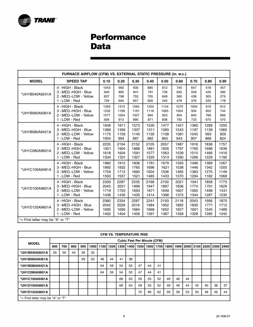
PerformanceData
CFM VS. TEMPERATURE RISE
MODELCubic Feet Per Minute (CFM)
600 700 800 900 1000 1100 1200 1300 1400 1500 1600 1700 1800 1900 2000 2100 2200 2300 2400
*UH1B040A9241A 59 50 44 39 35
*UH1B060A9361A 59 53 48 44 41 38
*UH1B080A9421A 64 59 54 50 47 44 41
*UH1C080A9601A 64 59 54 50 47 44 41
*UH1C100A9481A 68 63 59 55 52 49 46 44
*UH1D100A9601A 68 63 59 55 52 49 46 44 42 40 38 37
*UH1D120A9601A 70 66 62 59 56 53 50 48 46 44
*= First letter may be "A" or "T"
FURNACE AIRFLOW (CFM) VS. EXTERNAL STATIC PRESSURE (in. w.c.)
MODEL SPEED TAP 0.10 0.20 0.30 0.40 0.50 0.60 0.70 0.80 0.90
*UH1B040A9241A
4 -3 -2 -1 -
HIGH - BlackMED.-HIGH - BlueMED.-LOW - YellowLOW - Red
1043940837729
992895798694
930841752657
885791705600
812726649545
740650560478
647559438376
518420305220
457390279178
*UH1B060A9361A
4 -3 -2 -1 -
HIGH - BlackMED.-HIGH - BlueMED.-LOW - YellowLOW - Red
135912321077926
131311991054913
126411611027895
12041116994871
11441065953836
10791004904792
1004934845733
919852768670
812744666570
*UH1B080A9421A
4 -3 -2 -1 -
HIGH - BlackMED.-HIGH - BlueMED.-LOW - YellowLOW - Red
1646136611751004
161113561159994
157313371145997
153013111130982
147712801108963
142112431081943
136011971045907
12891139993866
12001060929824
*UH1C080A9601A
4 -3 -2 -1 -
HIGH - BlackMED.-HIGH - BlueMED.-LOW - YellowLOW - Red
2235192116181334
2194190416041331
2152188815911327
2105186115771320
2057183515631313
1987179715391290
1916176015151266
1836169814661229
1757163614161192
*UH1C100A9481A
4 -3 -2 -1 -
HIGH - BlackMED.-HIGH - BlueMED.-LOW - YellowLOW - Red
1982189217591593
1912183217121557
1836176516601521
1761169616041485
1679162115361433
1593153814651370
1496144613831294
1389134212751182
1267120511491068
*UH1D100A9601A
4 -3 -2 -1 -
HIGH - BlackMED.-HIGH - BlueMED.-LOW - YellowLOW - Red
2339204517191436
2287202117031430
2235199616931430
2168194716711414
2100189716491398
2021183616071372
1941177415651344
1858170114981287
1773162914311230
*UH1D120A9601A
4 -3 -2 -1 -
HIGH - BlackMED.-HIGH - BlueMED.-LOW - YellowLOW - Red
2380204216951402
2334202916901404
2287201616841406
2241198416681397
2193195216521387
2118189216271358
2043183016011328
1956177115451285
1870171214891242
*= First letter may be "A" or "T"
22-1836-07 9
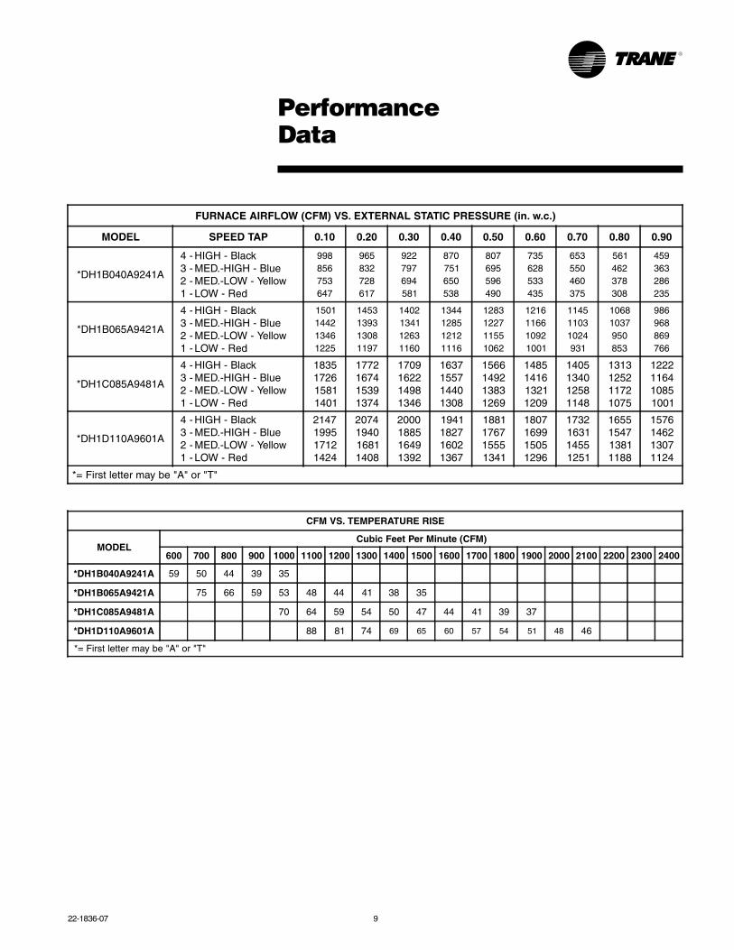
CFM VS. TEMPERATURE RISE
MODELCubic Feet Per Minute (CFM)
600 700 800 900 1000 1100 1200 1300 1400 1500 1600 1700 1800 1900 2000 2100 2200 2300 2400
*DH1B040A9241A 59 50 44 39 35
*DH1B065A9421A 75 66 59 53 48 44 41 38 35
*DH1C085A9481A 70 64 59 54 50 47 44 41 39 37
*DH1D110A9601A 88 81 74 69 65 60 57 54 51 48 46
*= First letter may be "A" or "T"
FURNACE AIRFLOW (CFM) VS. EXTERNAL STATIC PRESSURE (in. w.c.)
MODEL SPEED TAP 0.10 0.20 0.30 0.40 0.50 0.60 0.70 0.80 0.90
*DH1B040A9241A
4 -3 -2 -1 -
HIGH - BlackMED.-HIGH - BlueMED.-LOW - YellowLOW - Red
998856753647
965832728617
922797694581
870751650538
807695596490
735628533435
653550460375
561462378308
459363286235
*DH1B065A9421A
4 -3 -2 -1 -
HIGH - BlackMED.-HIGH - BlueMED.-LOW - YellowLOW - Red
1501144213461225
1453139313081197
1402134112631160
1344128512121116
1283122711551062
1216116610921001
114511031024931
10681037950853
986968869766
*DH1C085A9481A
4 -3 -2 -1 -
HIGH - BlackMED.-HIGH - BlueMED.-LOW - YellowLOW - Red
1835172615811401
1772167415391374
1709162214981346
1637155714401308
1566149213831269
1485141613211209
1405134012581148
1313125211721075
1222116410851001
*DH1D110A9601A
4 -3 -2 -1 -
HIGH - BlackMED.-HIGH - BlueMED.-LOW - YellowLOW - Red
2147199517121424
2074194016811408
2000188516491392
1941182716021367
1881176715551341
1807169915051296
1732163114551251
1655154713811188
1576146213071124
*= First letter may be "A" or "T"
PerformanceData
10 22-1836-07
ElectricalData
TUH1 Wiring
From Dwg. D343498 Rev. 2
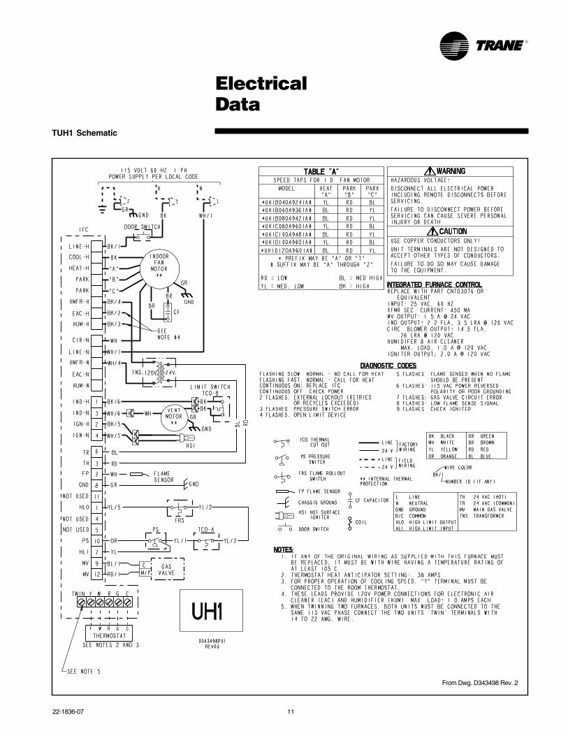
22-1836-07 11
TUH1 Schematic
ElectricalData
From Dwg. D343498 Rev. 2
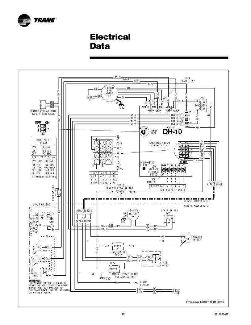
12 22-1836-07
From Dwg. D343814P01 Rev.0
ElectricalData
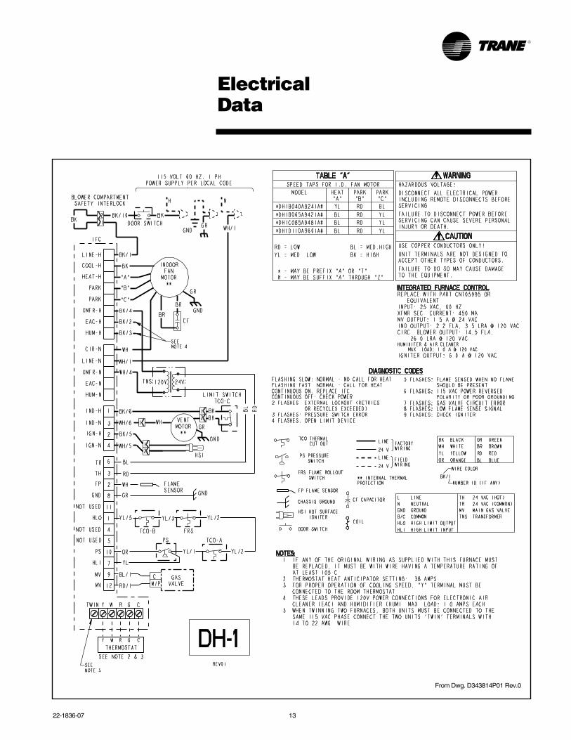
22-1836-07 13
From Dwg. D343814P01 Rev.0
ElectricalData
14 22-1836-07
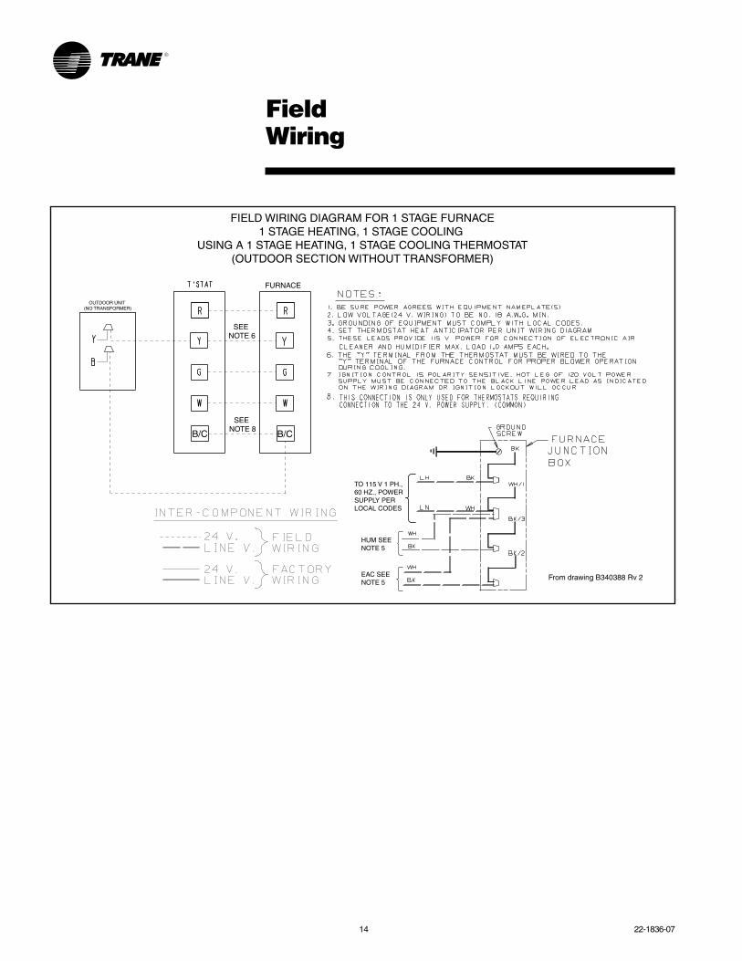
FieldWiring
OUTDOOR UNIT (NO TRANSFORMER)
SEE NOTE 6
From drawing B340388 Rv 2
SEE NOTE 8
FURNACE
B/CB/C
TO 115 V 1 PH.,60 HZ., POWERSUPPLY PERLOCAL CODES
HUM SEENOTE 5
EAC SEENOTE 5
FIELD WIRING DIAGRAM FOR 1 STAGE FURNACE1 STAGE HEATING, 1 STAGE COOLING
USING A 1 STAGE HEATING, 1 STAGE COOLING THERMOSTAT(OUTDOOR SECTION WITHOUT TRANSFORMER)
22-1836-07 15
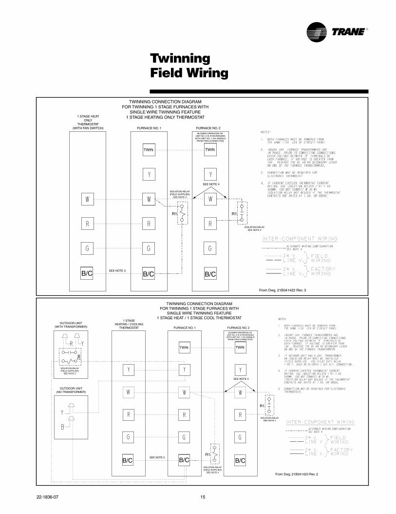
TwinningField Wiring
TWIN TWIN
R1 R1
TWINNING CONNECTION DIAGRAMFOR TWINNING 1 STAGE FURNACES WITH
SINGLE WIRE TWINNING FEATURE1 STAGE HEATING ONLY THERMOSTAT1 STAGE HEAT
ONLYTHERMOSTAT
(WITH FAN SWITCH) FURNACE NO. 1 FURNACE NO. 2
BLOWER OPERATION OF UNIT NO. 2 IS SYNCRONIZEDWITH UNIT NO. 1 VIA SIGNALS
FROM TWIN CONNECTION.
SEE NOTE 4
SEE NOTE 3
ISOLATION RELAY(FIELD SUPPLIED)
SEE NOTE 4
ISOLATION RELAYSEE NOTE 4
B/CB/CB/C
From Dwg. 21B341422 Rev. 3
TWIN TWIN
R1
R1
TWINNING CONNECTION DIAGRAMFOR TWINNING 1 STAGE FURNACES WITH
SINGLE WIRE TWINNING FEATURE1 STAGE HEAT / 1 STAGE COOL THERMOSTAT
1 STAGEHEATING / COOLING
THERMOSTAT FURNACE NO. 1 FURNACE NO. 2
BLOWER OPERATION OF UNIT NO. 2 IS SYNCRONIZEDWITH UNIT NO. 1 VIA SIGNALS
FROM TWIN CONNECTION.
SEE NOTE 4
SEE NOTE 5
ISOLATION RELAY(FIELD SUPPLIED)
SEE NOTE 4
ISOLATION RELAYSEE NOTE 4
OUTDOOR UNIT(NO TRANSFORMER)
OUTDOOR UNIT(WITH TRANSFORMER)
RC
ISOLATION RELAY(FIELD SUPPLIED)
SEE NOTE 3
B/CB/CB/C
From Dwg. 21B341423 Rev. 2
16 22-1836-07
From
Dw
g. C
3418
84
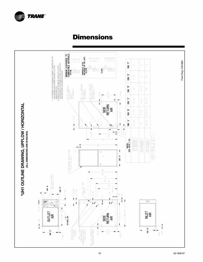
Dimensions
1. *
UH1D
120A
9601
AND
*UH1
B080
A942
1 RE
QUIR
E 3”
DIA
MET
ER V
ENT
PIPE
.
*UH1
C100
A948
1 &
UH1D
100A
9601
REQ
UIRE
S 2-
1/2”
OR
3”
DIA
MET
ER V
ENT
PIPE
.2.
DIA
MET
ER O
F VE
NT P
IPE
MAY
BE
LIM
ITED
TO
2-1/
2” O
R 3”
O
N SO
ME
MOD
ELS
AT D
IFFE
RENT
ALT
ITUD
ES.
REFE
R TO
THE
V
ENT
LENG
TH TA
BLE
FOR
PROP
ER A
PPLI
CATI
ON.
*UH
1 O
UTL
INE
DR
AW
ING
, UP
FLO
W /
HO
RIZ
ON
TAL
(ALL
DIM
EN
SIO
NS
AR
E IN
INC
HE
S)
22-1836-07 17
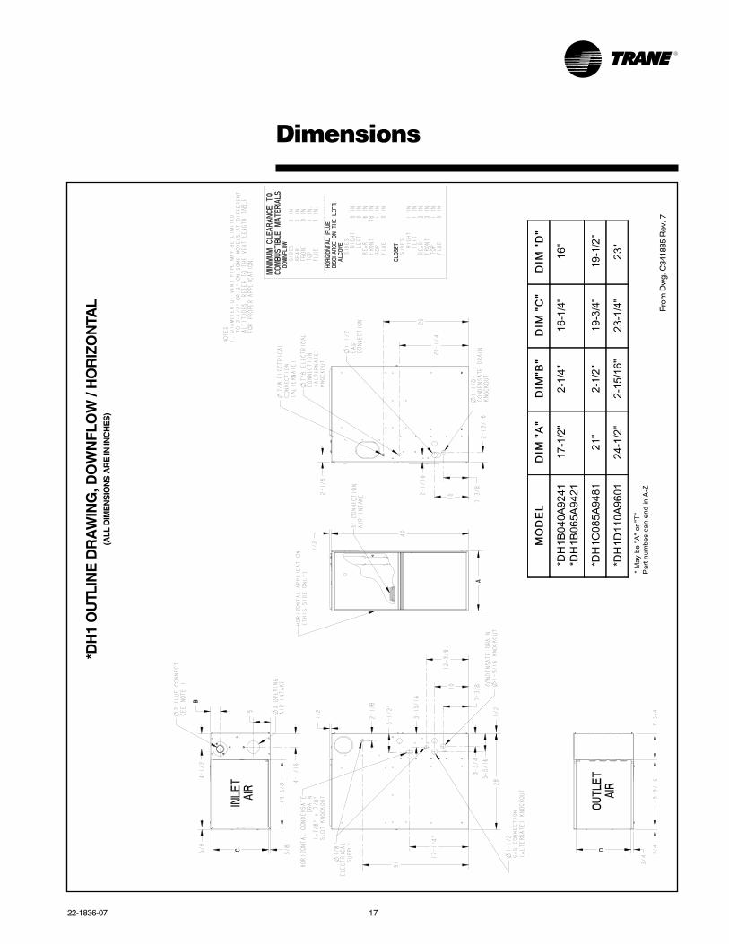
Dimensions
Fro
m D
wg.
C34
1885
Rev
. 7
*DH
1 O
UTL
INE
DR
AW
ING
, DO
WN
FLO
W /
HO
RIZ
ON
TAL
(ALL
DIM
EN
SIO
NS
AR
E IN
INC
HE
S)
�����
����
����
�����
�����
�����������
������� ���
�������
������
�������
���
������� ���
���
������
������
������
�����������
�������
��� ����
�������
���
������������������
����� !"��#�$� �� %�& ��'
Trane has a policy of continuous product and product data improvement and it reserves the right tochange design and specifications without notice.
Trane6200 Troup HighwayTyler, TX 75707www.trane.com
Literature Order Number 22-1836-07
File Number 22-1836-07
Supersedes 22-1836-05
Date 08/11