UP TO 25 TONS OF FORCE OUTPUT - renold.com · Flow Aids Model selection or sizing of Renold AJAX...
12
UP TO 25 TONS OF FORCE OUTPUT Sizing examples and equations for selecting vibrators KBM models match competitive mounting holes Factory support engineering More value and quality per pound of force output Continuous duty Inverter duty rated CE certification Thermal protection option www.renold.com Rotary Electric Vibrators Applications for Flow Aids, Densification and Metering
-
Upload
duongxuyen -
Category
Documents
-
view
214 -
download
0
Transcript of UP TO 25 TONS OF FORCE OUTPUT - renold.com · Flow Aids Model selection or sizing of Renold AJAX...

UP TO 25 TONS OF FORCE OUTPUT
Sizing examples and equations for selecting vibrators
KBM models match competitive mounting holes
Factory support engineering
More value and quality per pound of force output
Continuous duty
Inverter duty rated
CE certification
Thermal protection option
www.renold.com
Rotary Electric VibratorsApplications for Flow Aids, Densification and Metering

2
AJAX R/KBM and R/KBC Series Rotary Electric Vibrators
The Renold AJAX R/KBM and R/KBC Series is the most economical vibrator drive available in the North American market today. No other electric vibrator motor delivers more value and quality per pound of force output. The new KBM series matches competitive mounting holes. Our full line consists of models operating at frequencies of 900, 1200, 1800 and 3600 RPM. Eccentric weights can be manually adjusted to vary the centrifugal force from 0 through 100%. A suitable model can be supplied for most any type application or environment, and are rated for continuous operation. Special features include: foot mounting, cast metal housing, Oʼring groove sealed end covers, increased corrosion protection, external ground lug with CE certification and optional 304SS end covers.
ApplicationsThe AJAX R/KBM and R/KBC Series Rotary Electric Vibrators are specifically suited for flow aids, densification, shake-out and metering of solid materials. Examples defined are related to Brute Force designs.
Flow Aids (page 3)
When moisture, temperature or grain size of material causes irregular flow through bins, hoppers, chutes, etc., vibration can be introduced to solve problems. AJAX vibrators break up bridging in storage vessels, keeping material in continuous motion and thus minimizing friction along the transporting body. As a general rule, both 1800 and 3600 RPM are utilized pending the type of application.
Densification or Shakeout (page 4)
Dual counter-rotating vibrators produce a rectilinear motion, which is ideal for increasing the density of material in a container. The result is 20-50% more material in the container and a reduction in containers, warehouse space and freight costs. The same principle in reverse will shake-out foundry molds. Refer to the densification chart for recommended frequencies and G-level. When using vibrators in a shake-out mode, add one (1.0) G-level to the densification chart.
Metering or Transporting (page 5)
Dual counter rotating vibrators attached to feeders, screeners, sorters and conveyors will meter and transport materials. Both vibrators synchronize producing a rectilinear motion at 30 degrees to the flow path. Special consideration must be given to fabricating a rugged mounting drive triangle as the vibrators must be attached to the same one-piece mounting structure. Here, 1200 and 900 RPM are generally the recommend frequency choices. Special attention must be given to the structures moment of inertia when exceeding 1200 RPM. A dual magnetic starter having a single starter with two overloads is required for operation (refer to page 11 diagram). Other enhancements include: variable speed control for tuning the flow rate or fast/dribble feed control and dynamic braking to cut off the flow immediately.
Why buy competitive brands whose services offer limited experience using vibrators? Renold offers personal or group training sessions reviewing the dynamics of designing vibratory structures critical to sizing vibrators.
TABLE OF CONTENTSR/KBM and R/KBC Series . . . . . . . . . . . . 2Flow Aids . . . . . . . . . . . . . . . . . . . . . . . . . 3Densification or Shake-out . . . . . . . . . . . 4Metering or Transporting . . . . . . . . . . . . . 53600 RPM Single Phase 110/1/60 & 230/460/3/60 . . . . . . . . . . . . . 61800 RPM 4 Pole 230/460/3/60 . . . . . . . 71200 RPM 6 Pole 230/460/3/60 . . . . . . . 8900 RPM 8 Pole 230/460/3/60 . . . . . . . . 9Setting of Eccentric Weight and Wiring Diagrams . . . . . . . . . . . . . . . 10Application Data Sheet and Capacitor Starter 115V. . . . . . . . . . . . . . 11

Flow AidsModel selection or sizing of Renold AJAX electric motor vibrators for bins, hoppers and silos is based upon a ratio of product weight in the sloped wall portion of the vessel and the force output (Fo) of the vibrator. The general rule should be 10:1, i.e., ten pounds of product to one pound of force output. Generally, the following frequencies are used as flow aids:
Determine the volume (V) of product in the sloped wall:
[Conical Shape] V = 1.0472 x vertical height x (R2 + (Rr) + r2)
Where: R = radius of the cone at the inlet r = radius of the cone at the discharge
[Square or Rectangular Shape] V = vertical height x (B + Bb + b) 3
Where: B = area of the pyramid at the inlet b = area of the pyramid at the discharge
Convert all dimensions to feet. Multiply the calculatedvolume by the bulk density of the product to find thetotal weight.
Determine the vertical height (Vh):
Where: Vh = tan O x X
ExampleFind the weight of material in the sloped wall of a 10 ft diameter silo having a 60 degree slope and a 12 inch discharge. The product will be dry free flowing plastic pellets uniform in size with a bulk density of 33 pcf.
Find the vertical height: Vh = tan 60 degrees x 4.5 ft = 1.732 x 4.5 ft = 7.794 ft
Find the volume of a conical vessel: V = 1.0472 x 7.794 ft x (52 + (5 x 1) + 12) = 1.0472 x 7.794 ft x (31) = 253 cu ft
Find the weight of product: W = 253 x 33 pcf = 8,349 lbs
Most bins and hoppers only require one (1) vibrator mounted 1/3 the total sloped distance from the discharge as shown. When product is very difficult to flow or the capacity in the sloped portion exceeds 25 tons, two or three vibrators may be required. The vibrators should be staggered at 90 degrees about the initial vibrator at 1/4 intervals thereafter. When in operation each vibrator should not be permitted to turn on simultaneously, but rather intermittently. The use of an on/off timer will be required.
3
FREquENCy CONdiTiON PROBLEM
3600 free flowing dry, continuous discharging, uniform product size
1800 irregular flow high moisture content, sticky, intervals between discharges
HIP
INITIAL VIBRATOR
CONTINUOUS CHANNEL OR ANGLES TO THE HIP
PROPER MOuNTiNG
HAND HOLES
STITCH WELD

Vibration is created by applying an alternating force to an isolated mass. The two critical factors when determining the proper vibration are amplitude and frequency. Amplitude is the distance through which the mass is moved from one extreme to another. Frequency is the number of times the mass is moved in a given period of time (RPMs). G-level is referred to as the ratio of force required to change the motion of a body (mass). Whereby, mass resists any change in motion. When dual vibrators are used to produce a rectilinear motion (up/down) for densification, we can calculate the size/model of a vibrator by knowing the material and its bulk density.
Stroke = Fo x C Twt x f2
G-level = Fo Twt
Pre-designExample: Find the vibrator size for a packer needed to densify a 48” square container with pallet having a target weight of 2500 lbs. The material is a granular powder @ 60 pcf. Assume the vibratory deck weight to be 850 lbs, and vibrators weighing 200 lbs each. Refer to the chart below and scan the density column with respect to type of material. We find the optimum frequency is 1200 RPM @ 2.5 G’s.
Twt = 850 lbs deck + 400 lbs vibrators + 2500 lbs load = 3750 lbs
If G-level equals Fo divided by Twt, thenFo = G-level x Twt
Find the vibrator Fo: Fo = 2.5 Gʼs x 3750 lbs
2 vibrators = 4687.5 lbs each vibrator
Refer to the 1200 RPM chart (page 8) and scan down the force output column and match the Fo calculated. We find the vibrators should be R/KBC-3-400-6. The maximum Fo of each vibrator is 5628 lbs. Therefore, the eccentric setting should be set at the following percentage:
% = 4687.5
5628 = 83%
NOTE: The energy level of 2.5 Gʼs is very large, and in this case we calculated for a full load vibration cycle. If the container requires vibration at various steps during the filling process, the eccentric setting should be reduced to match the first vibration setpoint. Side restraints may be required to contain the pallet/container to prevent walking off the vibratory deck, as the flow into the box may not be directly into the center.
4
Densification or Shake Out
RESULTANTSTROKE
Foods Feeds
Chemicals
Foundry
Refractory
Industrial
CroutonsPowders/Resins
Pellets/Feed Plastic
Powders/Lime
Powders/MetalSand (air set)Sand (green)
Mixes
Hard Goods (misc parts) Stampings
1-1520-6035-50
60-90
100-200100
80-10090-110
50/150
1200/2.5900/2.0900/2.0
1200/2.01200/2.5 1800/2.03600/2.03600/1.01800/1.51800/2.5 3600/2.0900/1.5
1200/1.5
1800/2.51200/2.01800/2.0
900/2.0 3600/2.01800/2.01800/2.03600/1.01200/2.5
1800/1.5
900/36001800/3600
3600
900/1200900/1200900/1200
900
3600
Optimum Acceptable NotRecommended
Recommended Frequency/G-LevelType
IndustryProduct (general)
Density (ppcf)

When dual motor vibrators are directly attached to a trough it is referred to as a “Brute Force” design. It is very simple to calculate the necessary vibrator size/model by finding the required force output (Fo), if you can project the desired stroke. The stroke, also referred to as amplitude (peak to peak), is the resultant action produced by these vibrators when properly isolated. The following chart depicts the maximum stroke electric vibrators should operate at a specific frequency in a brute force design. As a rule of thumb, the feed rate will most likely be considered to be approximately 35 FPM.
Stroke = Fo x C
Twt x f2
Where: Fo = the total force output of the vibrator(s) C = a constant having a numerical value of 70470.91 Twt = total weight, combined value of the trough, vibrator(s) weight and load f2 = frequency squared
Pre-designExample: Find the vibrator size for a feeder needing todeliver 75 TPH of sand @ 100 pcf. Assume the panwidth to be 30” wide and 72” long. Also for this exampleassume the trough weight is 495 lbs and 1200 RPMvibrators @ 150 lbs each.
Find the depth of product flow:
75 TPH = 60 sec. x 1.0 x 30” wide x depth x 100 pcf x 35 FPM
144 in.2 x 2000 lbs
Depth = 3.43”, your sides on the trough should bea minimum of twice this value.
Find the load of material in the trough: 3.43” x 30” x 72”
x 100 pcf = 428.75 lbs 12” x 12” x 12”
Find the total vibrated weight Twt:495 lbs trough + 300 lbs vibrators + 428 lbs load = 1223 lbs
Stroke 0.25” = 2Fo x 70470.91 2 vibrators
1223 lbs x 12002
Fo = 3123 lbs minimum for each vibrator
Refer to the 1200 RPM chart (page 8) and scan downthe force output column and match the Fo calculated.We find the vibrators should be R/KBC3-350-6, havinga maximum force output of 3988 lbs. Since thecalculated Fo needs to be 3123 lbs, the vibratorscan be set to the following percentage.
NOTE: In this pre-design there were assumptions madesuch as trough and vibrator weight. Always re-checkyour calculations with real values.
% = 3123
3988 = 78%
Remove the end covers and change the eccentricpercentage (page 10). Keep the covers off and start thevibrators (momentarily) to verify each vibrator is counterrotating, i.e. one running CW and the other CCW.BE SAFE – insure there isn’t any person or obstaclenear the vibrators during this check. Once rotation iscorrect, disconnect power, and install both end covers.The equipment is ready for final testing.
See page 10 (Setting Eccentric Weights) for mounting orientation of vibrators on feeders.
5
Metering or Transporting
RPM MAX. STROKE
900 0.375” 1200 0.250” 1800 0.125” 3600 0.063”

6
Mode HP Max Amp Wt Unbal Draw A B C D E F H K N P S S Force Draw (lbs) (in-lbs) Ref Metric (lbs) 115/1/60
R/VBM 2MS 0.04 71 0.15 3.5 0.2 #1 1.26 3.62 0.35 2.40 2.17 4.37 1.34 5.75 0.87 2.76 0.28 7 R/KBM 1.5-2S 0.20 226 1.40 10 0.6 #1 2.44 4.17 0.39 4.13 3.89 5.91 2.36 8.35 1.38 5.71 0.35 9 R/KBM 2.5-2S 0.24 421 1.50 11 1.1 #1 2.95 4.13 0.39 4.13 3.89 5.91 2.36 8.35 1.38 5.71 0.35 9 R/KBM 4-2S 0.24 615 1.50 12 1.7 #1 2.76 5.12 0.39 4.13 3.89 5.91 2.36 8.35 1.38 5.71 0.35 9 R/KBM 6-2S 0.36 1003 2.80 20 2.7 #1 3.54 4.92 0.47 5.12 4.72 6.54 2.95 10.24 1.57 7.28 0.51 13 R/KBM 12-2S 0.68 2168 4.50 46 5.9 #1 3.94 6.29 0.63 5.95 5.35 7.48 3.35 11.34 1.57 8.07 0.51 13
R/KBM 6-4S 0.14 259 1.0 12 0.7 #1 2.44 4.17 0.39 4.13 3.89 5.91 2.36 9.06 1.38 5.71 0.35 9 R/KBM 16-4S 0.27 679 1.8 22 1.8 #1 3.54 4.92 0.47 5.12 4.72 6.54 2.95 11.73 1.57 7.28 0.51 13
R/KBM
3600 RPM Single Phase 110/1/60
R/KBM
1800 RPMSingle Phase 110/1/60
Model HP Max Amp Draw Wt Unbal Draw A B C D E F H K N P S S Force Force (lbs) (in-lbs) Ref Dia Metric (lbs) (lbs) 230 460
R/VBM 2M 0.04 71 0.2 .08 3.5 0.2 #1 1.26 3.62 0.35 2.40 2.17 4.37 1.34 5.75 0.87 2.76 0.28 7 R/KBM 1.5-2 0.20 226 0.6 0.3 10 0.6 #1 2.44 4.17 0.39 4.13 3.89 5.91 2.36 8.35 1.38 5.71 0.35 9 R/KBM 2.5-2 0.24 421 0.6 0.3 11 1.1 #1 2.95 4.13 0.39 4.13 3.89 5.91 2.36 8.35 1.38 5.71 0.35 9 R/KBM 4-2 0.24 615 0.6 0.3 12 1.7 #1 2.76 5.12 0.39 4.13 3.89 5.91 2.36 8.35 1.38 5.71 0.35 9 R/KBM 6-2 0.36 1003 1.0 0.5 20 2.7 #1 3.54 4.92 0.47 5.12 4.72 6.54 2.95 10.24 1.57 7.28 0.51 13 R/KBM 12-2 0.68 2168 1.6 0.8 46 5.9 #1 3.94 6.29 0.63 5.95 5.35 7.48 3.35 11.34 1.57 8.07 0.51 13 R/KBM 18-2 0.81 2783 1.8 0.9 71 7.6 #1 4.72 6.69 0.79 7.13 6.29 8.27 3.98 13.98 1.69 9.29 0.67 17 R/KBM 20-2 1.08 3397 2.2 1.1 75 9.2 #1 4.72 6.69 0.79 7.13 6.29 8.27 3.98 13.98 1.69 9.29 0.67 17
3600 RPM2 Pole 230/460/3/60
* Technical data upon request
TyPE R/KBM110/1/60 w/CAPACiTOR
TyPE R/KBM230/460/3/60
TyPE R/KBM dWG #1

7
Model HP Max Amp Draw Wt Unbal Draw A B C D E F G H K N O P S S Force (lbs) (in-lbs) Ref Dia Metric (lbs) 230 460
R/KBM 2.5-4 0.11 97 0.4 0.2 10 1.1 #1 2.44 4.17 0.39 4.13 3.89 5.91 5.12 2.36 8.35 1.38 1.18 5.71 0.35 9 R/KBM 4-4 0.14 194 0.4 0.2 11 2.1 #1 2.44 4.17 0.39 4.13 3.89 5.91 5.12 2.36 8.35 1.38 1.18 5.71 0.35 9 R/KBM 6-4 0.14 259 0.4 0.2 13 2.8 #1 2.44 4.17 0.39 4.13 3.89 5.91 5.12 2.36 9.06 1.38 1.18 5.71 0.35 9 R/KBM 16-4 0.24 679 0.8 0.4 24 7.4 #1 3.54 4.92 0.47 5.12 4.72 6.54 6.3 2.95 11.73 1.57 1.18 7.28 0.51 13 R/KBM 30-4 0.42 1294 1.1 0.6 55 14.1 #1 3.94 6.29 0.63 5.95 5.35 7.48 7.36 3.35 13.78 1.57 1.30 8.07 0.51 13 R/KBM 40-4 0.46 1618 1.2 0.6 57 17.6 #1 3.94 6.29 0.63 5.95 5.35 7.48 7.36 3.35 13.78 1.57 1.30 8.07 0.51 13 R/KBM 55-4 0.68 2297 1.6 0.8 77 25 #1 4.72 6.69 0.79 7.13 6.29 8.27 8.5 3.98 13.98 1.69 1.57 9.29 0.67 17 R/KBM 90-4 0.81 3559 2.0 1.0 90 38.7 #1 4.72 6.69 0.79 7.13 6.29 8.27 8.5 3.98 16.34 1.69 1.57 9.29 0.67 17 R/KBC 1-55-4 0.7 1516 1.8 0.9 76 16.5 #2 5.51 6.69 0.79 7.13 6.89 8.27 8.5 3.98 13.98 1.69 1.38 9.29 0.67 20 R/KBC 1-90-4 0.9 2447 2.28 1.14 90 26.6 #2 5.51 6.69 0.79 7.13 6.89 8.27 8.5 3.98 16.34 1.69 1.38 9.29 0.67 20 R/KBC 2-120-4 1.5 3224 3 1.5 112 35.1 #2 5.51 6.69 0.98 8.62 7.36 8.66 10.16 4.8 17.56 1.77 1.77 10.24 0.87 25 R/KBC 2-160-4 1.7 4311 4 2 128 46.9 #2 5.51 6.69 0.98 8.62 7.36 8.66 10.16 4.8 19.21 1.77 1.77 10.24 0.87 25 R/KBC 3-200-4 2.4 5399 6.2 3.1 187 58.7 #2 5.51 6.69 1.06 9.41 8.27 10.83 10.16 5.2 20.47 2.76 2.17 12.2 0.87 27 R/KBC 5-300-4 3.2 8079 9.4 4.7 254 87.9 #3 3.27 9.02 1.38 11.14 9.84 12.2 12.8 6.77 22.83 2.56 2.44 15.35 0.87 35 R/KBC 5-400-4 4.4 10798 9.8 4.9 342 117.4 #3 3.27 9.02 1.38 12.17 9.84 12.2 13.98 6.77 23.62 2.56 2.44 15.35 0.87 35 R/KBC 8-500-4 8 14138 19 9.5 454 153.8 #3 4.13 11.02 1.38 13.66 10.63 14.17 15.67 7.52 25.12 2.76 2.36 16.3 1.02 26 R/KBC 8-650-4 10.7 17245 23 11.5 516 187.5 #3 4.13 11.02 1.38 13.66 10.63 14.17 15.67 7.52 25.67 2.76 2.36 16.3 1.02 26 R/KBC 11-650-4 10.7 17517 23 11.5 650 190.5 #3 4.92 12.6 1.65 16.18 13.78 15.75 18.11 8.86 27.8 3.35 3.15 17.64 1.26 42 R/KBC 11-700-4 11.4 18877 24 12 684 205.3 #3 4.92 12.6 1.65 16.18 13.78 15.75 18.11 8.86 27.8 3.35 3.15 17.64 1.26 42 R/KBC 11-900-4 14.8 24275 32 16 827 264 #3 4.92 12.6 1.65 16.18 13.78 15.75 18.11 8.86 30.83 3.35 3.15 17.64 1.26 42
1800 RPM 4 Pole 230/460/3/60
TyPE R/KBM TyPE R/KBC5 – R/KBC11TyPE R/KBC1 – R/KBC3
TyPE R/KBM dWG #1 TyPE R/KBC5 – R/KBC11 dWG #3TyPE R/KBC1 – R/KBC3 dWG #2

8
Model HP Max Amp Draw Wt Unbal Draw A B C D E F G H K N O P S S Force (lbs) (in-lbs) Ref Dia Metric (lbs) 230 460
R/KBM 6-6 0.12 129 0.6 0.3 13 3.2 #1 2.44 4.17 0.39 4.13 3.89 5.91 – 2.36 9.06 1.38 – 5.71 0.35 9 R/KBM 15-6 0.19 291 1.2 0.6 25 7.1 #1 3.54 4.92 0.47 5.12 4.72 6.54 – 2.95 11.73 1.57 – 7.28 0.51 13 R/KBM 30-6 0.32 582 0.8 0.4 55 14.2 #1 3.94 6.29 0.63 5.95 5.35 7.48 – 3.35 13.78 1.57 – 8.07 0.51 13 R/KBM 40-6 0.35 712 1.0 0.5 57 17.4 #1 3.94 6.29 0.63 5.95 5.35 7.48 – 3.35 13.78 1.57 – 8.07 0.51 13 R/KBM 60-6 0.43 1035 1.2 0.6 77 25.3 #1 4.72 6.69 0.79 7.13 6.29 8.27 8.5 3.98 13.98 1.69 1.57 9.29 0.67 17 R/KBM 90-6 0.61 1535 1.8 0.9 90 37.6 #1 4.72 6.69 0.79 7.13 6.29 8.27 8.5 3.98 16.34 1.69 1.57 9.29 0.67 17 R/KBC 1-60-6 0.5 967 1.36 0.68 76 23.7 #2 5.51 6.69 0.79 7.13 6.89 8.27 8.5 3.98 13.98 1.69 1.38 9.29 0.67 20 R/KBC 1-90-6 0.7 1226 1.9 0.95 90 30 #2 5.51 6.69 0.79 7.13 6.89 8.27 8.5 3.98 16.34 1.69 1.38 9.29 0.67 20 R/KBC 2-165-6 1.1 1985 2.6 1.3 126 48.6 #2 5.51 6.69 0.98 8.62 7.36 8.66 10.16 4.8 19.21 1.77 1.77 10.24 0.87 25 R/KBC 2-200-6 1.2 2279 3.2 1.6 143 55.8 #2 5.51 6.69 0.98 8.62 7.36 8.66 10.16 4.8 21.42 1.77 1.77 10.24 0.87 25 R/KBC 2-240-6 1.2 2848 3.2 1.6 154 69.7 #2 5.51 6.69 0.98 8.62 7.36 8.66 10.16 4.8 21.42 1.77 1.77 10.24 0.87 25 R/KBC 3-325-6 1.9 4264 4.6 2.3 209 104.3 #2 5.51 6.69 1.06 9.41 8.27 10.83 10.94 5.2 22.83 2.76 2.17 12.2 0.87 27 R/KBC 3-350-6 1.9 4592 4.6 2.3 227 112.4 #2 5.51 6.69 1.06 9.41 8.27 10.83 10.94 5.2 25 2.76 2.17 12.2 0.87 27 R/KBC 3-400-6 1.9 5628 4.6 2.3 238 137.7 #2 5.51 6.69 1.06 9.41 8.27 10.83 10.94 5.2 25 2.76 2.17 12.2 0.87 27 R/KBC 5-520-6 2.8 7009 8.4 4.2 304 171.5 #3 3.27 9.02 1.38 11.14 9.84 12.2 12.8 6.18 25.59 2.56 2.44 15.35 0.87 35 R/KBC 5-815-6 4 10755 10 5 423 263.2 #3 3.27 9.02 1.38 12.17 9.84 12.2 13.98 6.77 27.83 2.56 2.44 15.35 0.87 35 R/KBC 8-1250-6 8 14121 19 9.5 551 345.5 #3 4.13 11.02 1.38 13.66 10.63 14.17 15.67 7.52 30.79 2.76 2.36 16.3 1.02 26 R/KBC 8-1530-6 11.4 18229 26 13 637 446.1 #3 4.92 12.6 1.65 16.18 13.78 15.75 18.11 8.86 33.31 3.35 3.15 17.64 1.26 32 R/KBC 11-1550-6 11.4 18229 26 13 816 446.1 #3 4.92 12.6 1.65 16.18 13.78 15.75 18.11 8.86 34.02 3.35 3.15 17.64 1.26 42 R/KBC 11-1730-6 11.8 20404 28.6 14.3 849 499.3 #3 4.92 12.6 1.65 16.18 13.78 15.75 18.11 8.86 34.02 3.35 3.15 17.64 1.26 42 R/KBC 11-2150-6 14.5 26412 33.4 16.7 891 646.3 #3 4.92 12.6 1.65 16.18 13.78 15.75 18.11 8.86 35.43 3.35 3.15 17.64 1.26 42 R/KBC 11-2400-6 14.6 27344 33 16.5 926 669.1 #3 4.92 12.6 1.65 16.18 13.78 15.75 18.11 8.86 35.43 3.35 3.15 17.64 1.77 42 R/KBC 15-2700-6 16.1 31090 37.2 18.6 1433 760.7 #4 5.51 18.9 1.77 19.57 20.47 22.64 21.46 10.63 37.44 3.94 3.54 21.65 1.77 45 R/KBC 15-3200-6 18.8 36459 43.4 21.7 1566 892.1 #4 5.51 18.9 1.77 19.57 20.47 22.64 21.46 10.63 37.44 3.94 3.54 21.65 1.77 45 R/KBC 20-4120-6 26.8 43105 56.8 28.4 2029 1054.7 #4 5.51 20.47 1.97 21.3 21.46 24.21 23.43 11.81 43.31 3.94 3.54 23.62 1.97 50
TyPE R/KBM TyPE R/KBC5 – R/KBC11TyPE R/KBC1 – R/KBC3
TyPE R/KBM dWG #1 TyPE R/KBC5 – R/KBC11 dWG #3TyPE R/KBC1 – R/KBC3 dWG #2
1200 RPM 6 Pole 230/460/3/60
9
Model HP Max Amp Draw Wt Unbal Draw A B C D E F G H K N O P S S Force (lbs) (in-lbs) Ref Dia Metric (lbs) 230 460
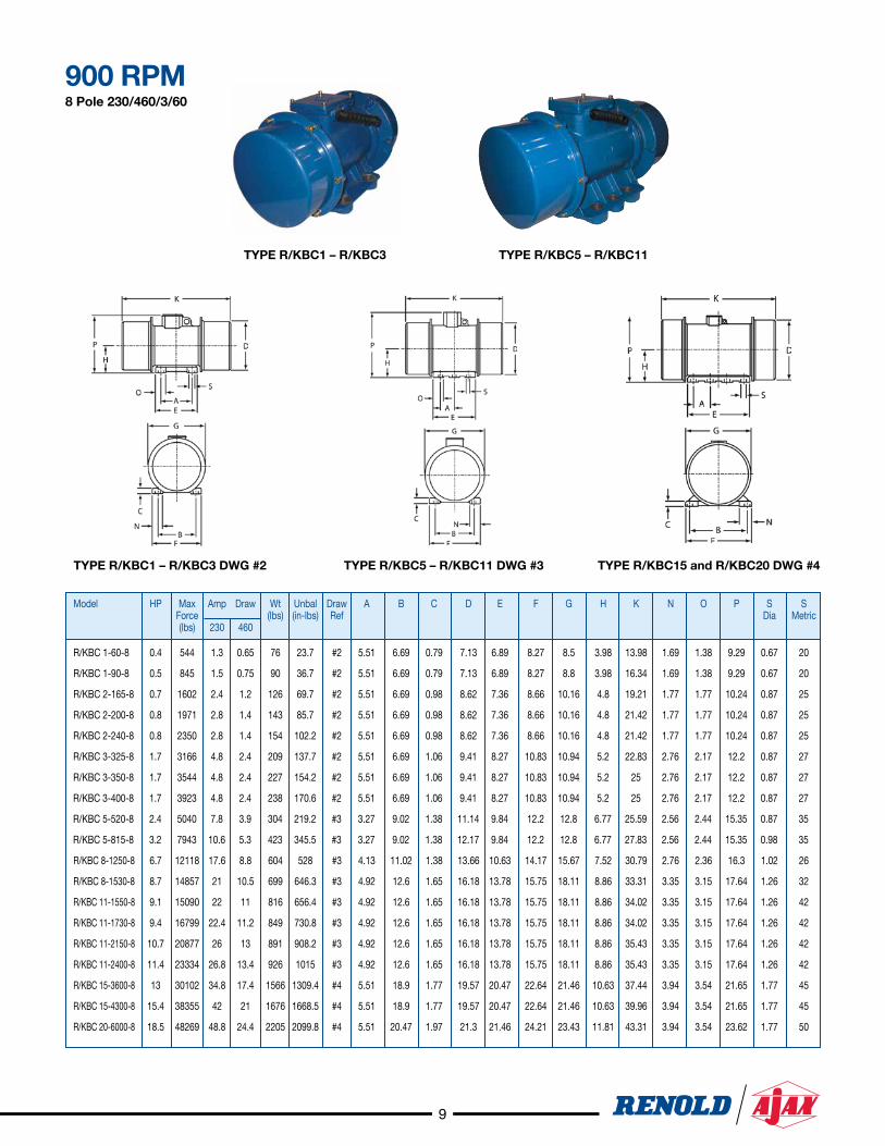
R/KBC 1-60-8 0.4 544 1.3 0.65 76 23.7 #2 5.51 6.69 0.79 7.13 6.89 8.27 8.5 3.98 13.98 1.69 1.38 9.29 0.67 20
R/KBC 1-90-8 0.5 845 1.5 0.75 90 36.7 #2 5.51 6.69 0.79 7.13 6.89 8.27 8.8 3.98 16.34 1.69 1.38 9.29 0.67 20
R/KBC 2-165-8 0.7 1602 2.4 1.2 126 69.7 #2 5.51 6.69 0.98 8.62 7.36 8.66 10.16 4.8 19.21 1.77 1.77 10.24 0.87 25
R/KBC 2-200-8 0.8 1971 2.8 1.4 143 85.7 #2 5.51 6.69 0.98 8.62 7.36 8.66 10.16 4.8 21.42 1.77 1.77 10.24 0.87 25
R/KBC 2-240-8 0.8 2350 2.8 1.4 154 102.2 #2 5.51 6.69 0.98 8.62 7.36 8.66 10.16 4.8 21.42 1.77 1.77 10.24 0.87 25
R/KBC 3-325-8 1.7 3166 4.8 2.4 209 137.7 #2 5.51 6.69 1.06 9.41 8.27 10.83 10.94 5.2 22.83 2.76 2.17 12.2 0.87 27
R/KBC 3-350-8 1.7 3544 4.8 2.4 227 154.2 #2 5.51 6.69 1.06 9.41 8.27 10.83 10.94 5.2 25 2.76 2.17 12.2 0.87 27
R/KBC 3-400-8 1.7 3923 4.8 2.4 238 170.6 #2 5.51 6.69 1.06 9.41 8.27 10.83 10.94 5.2 25 2.76 2.17 12.2 0.87 27
R/KBC 5-520-8 2.4 5040 7.8 3.9 304 219.2 #3 3.27 9.02 1.38 11.14 9.84 12.2 12.8 6.77 25.59 2.56 2.44 15.35 0.87 35
R/KBC 5-815-8 3.2 7943 10.6 5.3 423 345.5 #3 3.27 9.02 1.38 12.17 9.84 12.2 12.8 6.77 27.83 2.56 2.44 15.35 0.98 35
R/KBC 8-1250-8 6.7 12118 17.6 8.8 604 528 #3 4.13 11.02 1.38 13.66 10.63 14.17 15.67 7.52 30.79 2.76 2.36 16.3 1.02 26
R/KBC 8-1530-8 8.7 14857 21 10.5 699 646.3 #3 4.92 12.6 1.65 16.18 13.78 15.75 18.11 8.86 33.31 3.35 3.15 17.64 1.26 32
R/KBC 11-1550-8 9.1 15090 22 11 816 656.4 #3 4.92 12.6 1.65 16.18 13.78 15.75 18.11 8.86 34.02 3.35 3.15 17.64 1.26 42
R/KBC 11-1730-8 9.4 16799 22.4 11.2 849 730.8 #3 4.92 12.6 1.65 16.18 13.78 15.75 18.11 8.86 34.02 3.35 3.15 17.64 1.26 42
R/KBC 11-2150-8 10.7 20877 26 13 891 908.2 #3 4.92 12.6 1.65 16.18 13.78 15.75 18.11 8.86 35.43 3.35 3.15 17.64 1.26 42
R/KBC 11-2400-8 11.4 23334 26.8 13.4 926 1015 #3 4.92 12.6 1.65 16.18 13.78 15.75 18.11 8.86 35.43 3.35 3.15 17.64 1.26 42
R/KBC 15-3600-8 13 30102 34.8 17.4 1566 1309.4 #4 5.51 18.9 1.77 19.57 20.47 22.64 21.46 10.63 37.44 3.94 3.54 21.65 1.77 45
R/KBC 15-4300-8 15.4 38355 42 21 1676 1668.5 #4 5.51 18.9 1.77 19.57 20.47 22.64 21.46 10.63 39.96 3.94 3.54 21.65 1.77 45
R/KBC 20-6000-8 18.5 48269 48.8 24.4 2205 2099.8 #4 5.51 20.47 1.97 21.3 21.46 24.21 23.43 11.81 43.31 3.94 3.54 23.62 1.77 50
TyPE R/KBC5 – R/KBC11 dWG #3TyPE R/KBC1 – R/KBC3 dWG #2
900 RPM 8 Pole 230/460/3/60
TyPE R/KBC15 and R/KBC20 dWG #4
TyPE R/KBC5 – R/KBC11TyPE R/KBC1 – R/KBC3

10
Setting of Eccentric WeightIf adjustments are made:
• insure both ends of the vibratorsʼ eccentric weights equal the same percentage value
• when utilizing dual vibrators in a configuration to produce a rectilinear motion; insure one is running CW, and one is running CCW
• when utilizing dual vibrators for feeders, and the outer eccentric weight is thinner than the inner weight, one vibrator must be rotated 180˚ so the vibrators synchronize when settings are less than 100% (It is a good rule to do this all of the time)
LIFTING LUGJUNCTION BOX
KBM KBC

11
Capacitor Starter Wiring diagram KBM, 115V
dETERMiNiNG BOLT LENGTHS• Add 1/8” for all washers• Add bolt diameter for nut height• Add 1/4” for thread past nut• Round stack-up dimensions to largest quarterEXAMPLE:2 1/16” = next size = 2 1/4” large bolt
Proper Hardware/Bolt Sizing
Note:1. You can not synchronize (2) vibrators with a single starter.2. You can hookup (2) vibrators to most VFDʼs, variable speed controllers
to synchronize.3. If you require a VFD, but also need Dynamic Braking Model, you must
include a dual magnetic starter in your controls.
Dual Magnetic StarterNotes:1. Fusible disconnect supplied by others.2. Control transformer always wired to customer
stated input voltage.3. Control wires are 18 awg.4. Overload size based upon amperage draw
and voltage.5. Motors should always be wired counter rotating.
Single Magnetic StarterNotes:1. Fusible disconnect supplied by others.2. Control transformer always wired to customer
stated input voltage.3. Control wires are 18 awg.4. Overload size based upon amperage draw
and voltage.5. Motor should always be wired to rotate into the
product load or flow.

R/KBC15 / Printed in U.S.A.
Renold Ajax100 Bourne StreetWestfield, NY 14787-0546Toll Free Tel: 1-800-879-2529
Renold Canada 622 Rue De Hull Ville La Salle Quebec, Canada H8R 1V9Toll Free Tel: 1-800-265-9970Tel: (514) 367-1764Fax: (514) 367-4993
www.renold.com