UNIVERSITY OF NAIROBI SCHOOL OF...
71
UNIVERSITY OF NAIROBI SCHOOL OF ENGINEERING DEPARTMENT OF ENVIRONMENTAL AND BIOSYSTEMS ENGINEERING PROJECT TITLE: DESIGN OF HYDROPONIC FODDER FACTORY CANDIDATE NAME: ONYANGO GORDON OCHIENG CANDIDATE NO: F21/1708/2010 SUPERVISOR’S NAME: ALBERT K. INIMA A Report Submitted in Partial Fulfillment for the Requirements of the Degree of Bachelor of Science in Environmental and Biosystems Engineering, of the University Of Nairobi MAY, 2015 FEB 540: ENGINEERING DESIGN PROJECT 2014/2015 ACADEMIC YEAR
Transcript of UNIVERSITY OF NAIROBI SCHOOL OF...

UNIVERSITY OF NAIROBI
SCHOOL OF ENGINEERING
DEPARTMENT OF ENVIRONMENTAL AND BIOSYSTEMS ENGINEERING
PROJECT TITLE: DESIGN OF HYDROPONIC FODDER FACTORY
CANDIDATE NAME: ONYANGO GORDON OCHIENG
CANDIDATE NO: F21/1708/2010
SUPERVISOR’S NAME: ALBERT K. INIMA
A Report Submitted in Partial Fulfillment for the Requirements of
the Degree of Bachelor of Science in Environmental and
Biosystems Engineering, of the University Of Nairobi
MAY, 2015
FEB 540: ENGINEERING DESIGN PROJECT
2014/2015 ACADEMIC YEAR

ONYANGO GORDON OCHIENG F21/1708/2010 Page i
DECLARATION
I, Onyango Gordon Ochieng, do declare that this report is my original work and to the best of my
knowledge, it has not been submitted for any degree award in any University or Institution.
Signed______________________________________________ Date ____________
ONYANGO GORDON OCHIENG
CERTIFICATION
I confirm that the work reported in this project was carried out by the candidate under my
supervision
Signed_______________________________________________Date_____________
Mr. ALBERT INIMA

ONYANGO GORDON OCHIENG F21/1708/2010 Page ii
DEDICATION
To my father for believing in me that I can do great things and my family for their support.

ONYANGO GORDON OCHIENG F21/1708/2010 Page iii
ACKNOWLEGEMENT
My sincere gratitude goes out to those that have assisted and supported me and made this project
possible. I wish to appreciate the Almighty God for His strength, provision and protection during
this project period.
My supervisor Mr. Albert Inima, who guided, advised, spent his time and assisted me in giving
my best to this design project.
The department of environmental and bio systems engineering was of great help to me in
providing materials, administrative and technical support.
My classmates, friends it‟s an appreciation for providing resources, advice and lively moments
that made this journey worth finishing.
May God bless you abundantly?
ONYANGO GORDON OCHIENG F21/1708/2010 Page iv
ABSTRACT
Hydroponic fodder production involves supplying cereal grain with moisture and nutrients, all
outside of a growing medium such as soil, and then harvesting the resulting green shoots and
root mat. The grain responds to the supply of moisture and nutrients by sprouting and then
producing a 200 – 250mm long vegetative green shoot with interwoven roots over a period of 5
to 8 days. At the end of the growing period the fodder is fed to livestock as a supplement in the
same way that hay and silage are currently.
Hydroponic fodder takes only 1 week (7 days) to mature as opposed to the normal Rhodes grass
that takes up to 12 weeks (84 days) to mature up and be readily fed to the animals.The growing
area of the fodder set up takes about 70% of the whole space.
Specialist sheds are built for the production of hydroponic fodder. The climate within these sheds
is actively controlled to ensure optimal growing conditions. A fodder shed measuring 10m x 13m
will produce approximately 1 tone of wet fodder per day.
The major problems faced by farmers in hydroponics is pondage of the water at the trays hence
the need to incorporate a drainage system as part of the structural design.
Fodder sheds produce a large quantity of green fodder, with 1kg of grain producing 6 - 10kg of
fodder sprouts. However, when this is converted back to a dry matter basis, there is a loss of
approximately 12% of the total dry matter in the grain. This loss is due to the consumption of
carbohydrates to produce energy within the grain during germination and other metabolic
activities of the growing sprouts.
There are also many types of grains that can be grown hydroponically. Grains such as oats,
barley, wheat, sorghum and corn have all been tried. However when choosing a seed the main
characteristics that come into play are their nutritional value, speed of seed growth and protein
levels.
While energy content of the fodder (MJ ME /kg DM) is similar to that of the barley grain, there
are some gains in protein and vitamin content of the fodder versus grain. Due to the costs of
fodder production, energy (MJME) and protein are 4 and 1.9 times more expensive respectively
in the fodder versus the grain.
The project will involve the design of sprinkler irrigation system including nozzle spacing, also
the sizing of pipes and pumps, design of an external reservoir according to the crop water
requirement of barley, and finally the design of a suitable drainage system including manholes.
Barley grass improves milk production in dairy cows. Additionally, milk from cows fed barley
grass contains higher grades of butter fat.
ONYANGO GORDON OCHIENG F21/1708/2010 Page v
LIST OF ACRONYMS
DM- dry matter
NFT- nutrient film technique
ETO- reference crop requirement
ETC- crop water requirement
NIR-net irrigation requirement
GIR- gross irrigation requirement
EC-electrical conductivity
P.E – Polyethylene pipes
K-pan-pan coefficient
E-pan- pan evaporation
SWR-Scheme water requirement
GAR- gross application rate
NAR-net application rate
PVC –polyvinyl chloride
ONYANGO GORDON OCHIENG F21/1708/2010 Page vi
Table of Contents 1.0 INTRODUCTION .................................................................................................................................. 1
1.1 STATEMENT OF PROBLEM & PROBLEM ANALYSIS .............................................................. 2
1.2 SITE ANALYSIS & INVENTORY ................................................................................................... 2
1.3 OVERALL OBJECTIVE .................................................................................................................... 4
1.3.1 SPECIFIC OBJECTIVES ............................................................................................................ 4
1.4 STATEMENT OF SCOPE ................................................................................................................. 4
2.0 LITERATURE REVIEW ....................................................................................................................... 6
2.1 Section A: Review of different types of hydroponic fodder systems ................................................. 7
2.2 ADVANTAGES AND LIMITATIONS OF HYDROPONIC FODDER ......................................... 13
3.0 THEORITICAL FRAMEWORK ......................................................................................................... 15
3.1Determination of water requirement .................................................................................................. 15
3.2 Drainage system ................................................................................................................................ 29
4.0 DESIGN SKETCHES ........................................................................................................................... 31
5.0 METHODOLOGY ............................................................................................................................... 39
5.1 Irrigation system (overhead irrigation system) ................................................................................. 39
5.2 Quality of space ................................................................................................................................ 41
6.0 RESULTS AND ANALYSIS ............................................................................................................... 43
6.1 ANALYSIS OF RESULTS .............................................................................................................. 43
6.2 Drainage system design .................................................................................................................... 47
7.0 CONCLUSSION AND RECOMMENDATION .................................................................................. 50
7.1 CONCLUSION ................................................................................................................................. 50
7.2 RECCOMMENDATION ................................................................................................................. 51
8.0 REFERENCES ..................................................................................................................................... 52
9.0 APPENDICES ...................................................................................................................................... 53
9.1 LIST OF TABLES ............................................................................................................................ 53
TABLE 1: Nutrient content of a range of feed sources .......................................................................... 53
FEED ...................................................................................................................................................... 53
DRY MATTER (%) ................................................................................................................................ 53
METABOLISABLE ENERGY (MJME/KGDM) .................................................................................. 53
CRUDE PROTEIN (CP %) .................................................................................................................... 53
Barley grain ............................................................................................................................................. 53

ONYANGO GORDON OCHIENG F21/1708/2010 Page vii
ONYANGO GORDON OCHIENG F21/1708/2010 Page 1
1.0 INTRODUCTION
Hydroponic gardening is the method of cultivating plants that does away with soil. In this
technique plants are grown inside greenhouses, with sport controlled environments and use water
as a medium of cultivation along with rich minerals and nutrients. Because we are largely doing
away with the necessity of soil, hydroponics is a method that can be used almost anywhere as it
takes up less space than field plants.
As population grows, there is obviously going to be more construction development going on,
creating less land available for farming, therefore the need to find ways to produce more food
and less land doing it and hydroponics is one way of doing that.
While there is a common notion that products that come from such method of cultivation are not
good for health due to the high use of nutrients and fertilizers, it is a perception rooted outside
reality. In fact, if we embrace hydroponic gardening and allow it to evolve as a competent
agriculture form, it holds unlimited potential that promises a future filled with riches.
The major problems faced by farmers in hydroponics is pondage of the water at the trays hence
the need to incorporate a drainage system as part of the structural design, also farmers have not
incorporated controlled environment thus the need to include temperature, humidity and PH
controls ,vertical farming could also be done in sky rappers and for that reason there could be an
urgent need to incorporate light splitters by just sufficiently augmenting the artificial lights from
the normal insolation using peripheral light concentrators
There are a number of challenges in producing hydroponic fodder. A common challenge that
causes many problems for those with fodder sheds is mold. Given the warm moist environment
within a fodder shed mold can easily take hold, ruin the crop and cause livestock health issues if
fed. Thus, active management of mold risk is essential.
There are also many types of grains that can be grown hydroponically. Grains such as oats,
barley, wheat, sorghum and corn have all been tried. However when choosing a seed the main
characteristics that come into play are their nutritional value, speed of seed growth and protein
levels. The seed that has all these qualities is - Malt Barley as it is highly nutritious with a very
high protein level and under the right conditions can grow to a height of 30 centimeters.
Shed design plays an important part in the success in growing cattle fodder hydroponically.
There are many types of shed designs on the market but the most important aspect to remember
when purchasing or setting up a Hydroponic Fodder Shed is the location of where the shed is
going to be constructed. It is of utter most importance to assemble a shed that is going to suit the
climatic condition of the region. Remembering to focus on either the cooling or heating benefits
of the unit to provide the best growing conditions possible for the fodder
ONYANGO GORDON OCHIENG F21/1708/2010 Page 2
Moldy sprouts have decreased livestock performance in trials, and have been known to result in
animal deaths. Mold is actively managed within sheds through pretreatment of the seed.
Additives to the water are used for pre-soaking the grain to minimize the risk of mold. Shed
hygiene is also important and thus considerable attention is paid to ensuring the growing trays
are well cleaned following each crop and prior to the sowing of the new crop.
There is a major problem for the existing designs of very high moisture feed thus the risk of
mould hence the need to incorporate a highly temperature controlled environment within the
greenhouse. Mold is a common problem that increases labor and costs, reduces animal
performance and sometimes results in stock deaths.
1.1 STATEMENT OF PROBLEM & PROBLEM ANALYSIS
The major problems faced by farmers in hydroponics is pondage of the water at the trays hence
the need to incorporate a drainage system as part of the structural design, achieved by outlaying
10 mm spacing ,1.5mm perforations within the trays thus excess water is channeled to the
peripheral drains.
Common pasture (Rhodes grass) takes about 12 weeks to mature thus the need to incorporate
hydroponic fodder system which takes 1 week (approximately 7 days to mature).
Handling of other fodders (mulberry fodder, nacadero fodder, grass, nippier grass) seems
cumbersome, including wastes associated with the same thus the need to come up with
hydroponic fodder.
Thus need for reduced lab our on fodder production for example cutting, carrying forage,
managing animals and adequate water supply, hydroponic fodder breaks the monotony of
handling and is usually consumed as a whole.
1.2 SITE ANALYSIS & INVENTORY
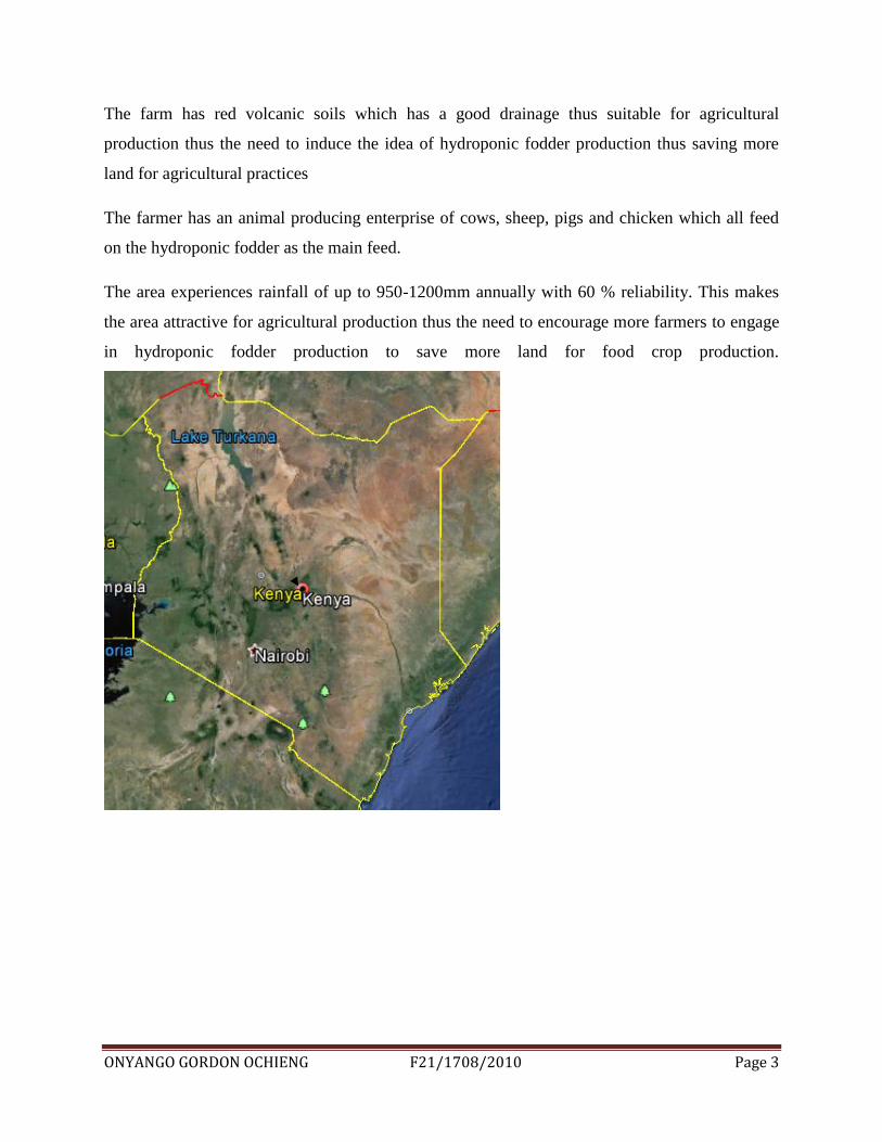
Muiga town is situated along Nyeri-Nyahururu road in central Kenya at latitude –o.316667/-
0®19” and longitude 36.9/36®53”.
Has an averagely large population which results into crafting of the land hence no fallow land
left for grazing.
There is a need to come up with a hydroponic fodder production mechanism to supplement on
the animal feed.
The farm has an altitude ranging from 2000-2500m above the sea level.
ONYANGO GORDON OCHIENG F21/1708/2010 Page 3
The farm has red volcanic soils which has a good drainage thus suitable for agricultural
production thus the need to induce the idea of hydroponic fodder production thus saving more
land for agricultural practices
The farmer has an animal producing enterprise of cows, sheep, pigs and chicken which all feed
on the hydroponic fodder as the main feed.
The area experiences rainfall of up to 950-1200mm annually with 60 % reliability. This makes
the area attractive for agricultural production thus the need to encourage more farmers to engage
in hydroponic fodder production to save more land for food crop production.

ONYANGO GORDON OCHIENG F21/1708/2010 Page 4
Figure 1: Muiga town location Source: goggle earth
1.3 OVERALL OBJECTIVE
To design a hydroponic fodder factory as means of providing fodder in urban areas.
1.3.1 SPECIFIC OBJECTIVES
To design an overhead irrigation system to replace the manual watering of the plants.
To determine the quality of space required in the design of the fodder factory.
To design a drainage system for the fodder factory
To determine adequate sizing of external reservoir for fodder water requirements.
1.4 STATEMENT OF SCOPE
The project will be centered on the site at Muiga town along Nyeri-Nyahururu road.
This project intends to focus on the design of a fodder factory including the layout of irrigation
system with overhead irrigation method, structural design of vertical cages for trays, guttering
system 4 drainage, cleaning area for trays, piping outlay will be determined with adequate pipe
sizing.
All this are done assuming an already existing greenhouse system, sizing of a reservoir assuming
an external water supply. The bill of quantities will also be established for the materials used.
ONYANGO GORDON OCHIENG F21/1708/2010 Page 5
Finally, every element of the project will be shown through AutoCAD and sketch up 3D
drawings.
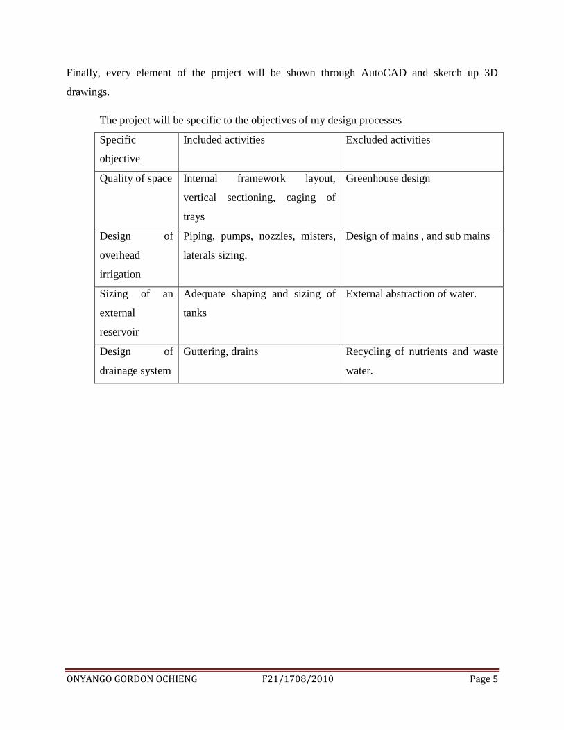
The project will be specific to the objectives of my design processes
Specific
objective
Included activities Excluded activities
Quality of space Internal framework layout,
vertical sectioning, caging of
trays
Greenhouse design
Design of
overhead
irrigation
Piping, pumps, nozzles, misters,
laterals sizing.
Design of mains , and sub mains
Sizing of an
external
reservoir
Adequate shaping and sizing of
tanks
External abstraction of water.
Design of
drainage system
Guttering, drains Recycling of nutrients and waste
water.
ONYANGO GORDON OCHIENG F21/1708/2010 Page 6
2.0 LITERATURE REVIEW
Hydroponic gardening is the method of cultivating plants that does away with soil. In this
technique plants are grown inside greenhouses, with sport controlled environments and use water
as a medium of cultivation along with rich minerals and nutrients. Because we are largely doing
away with the necessity of soil, hydroponics is a method that can be used almost anywhere as it
takes up less space than field plants .As population grows, there is obviously going to be more
construction development going on, creating less land available for farming, therefore the need
to find ways to produce more food and less land doing it and hydroponics is one way of doing
that.
While there is a common notion that products that come from such method of cultivation are not
good for health due to the high use of nutrients and fertilizers, it is a perception rooted outside
reality. In fact, if we embrace hydroponic gardening and allow it to evolve as a competent
agriculture form, it holds unlimited potential that promises a future filled with riches.
The major problems faced by farmers in hydroponics is pondage of the water at the trays hence
the need to incorporate a drainage system as part of the structural design, also farmers have not
incorporated controlled environment thus the need to include temperature, humidity and PH
controls ,vertical farming could also be done in sky rappers and for that reason there could be an
urgent need to incorporate light splitters by just sufficiently augmenting the artificial lights from
the normal insolation using peripheral light concentrators.
Hydroponic fodder production involves supplying cereal grain with moisture and nutrients, all
outside of a growing medium such as soil, and then harvesting the resulting green shoots and
root mat. The grain responds to the supply of moisture and nutrients by sprouting and then
producing a 200 – 250mm long vegetative green shoot with interwoven roots over a period of 5
to 8 days.
Being 30-50% faster in growth than the soil planting; these hydroponic growing systems
actually uses water to mix the nutrients to get their way to the root system enabling the plant to
utilize much energy for fruit making besides the search process(that plants do to search nutrients
in the soil in non-hydroponics systems).
ONYANGO GORDON OCHIENG F21/1708/2010 Page 7
A range of cereals can be utilized for fodder production, including barley, oats, wheat and maize.
The most commonly used cereal grain is barley. Barley fodder systems are the focus of the
analysis within this report. The amount of sprouts produced (yield) and quality of the fodder is
influenced by a number of factors including:
Grain - grain quality, grain variety and treatments
Growing environment - temperature, humidity and incidence of mold
Management of the system - water quality and pH, soaking time, nutrient supply, depth
and density of grain in troughs, and growing duration
Testing pH in these hydroponic growing systems is also important however mostly plants
grow within the 5.8-6.8 pH range. Moreover to direct the nutrients to the plant various
mediums are used like Rockwool and perlite. The main components of the design
includes constructing a bell syphon to cater for drainage, bubbler bucket system for
spraying, easy and effective automated PH controller, water chiller ,light splitter and a
water culture system.
2.1 Section A: Review of different types of hydroponic fodder systems
The existing design approaches includes wick flow system, ebb and flow system etc.
Types of Systems
Basic wick
Non-circulating raft system or deep water
Top feed/Drip
NFT (nutrient film technique)
Ebb and Flow
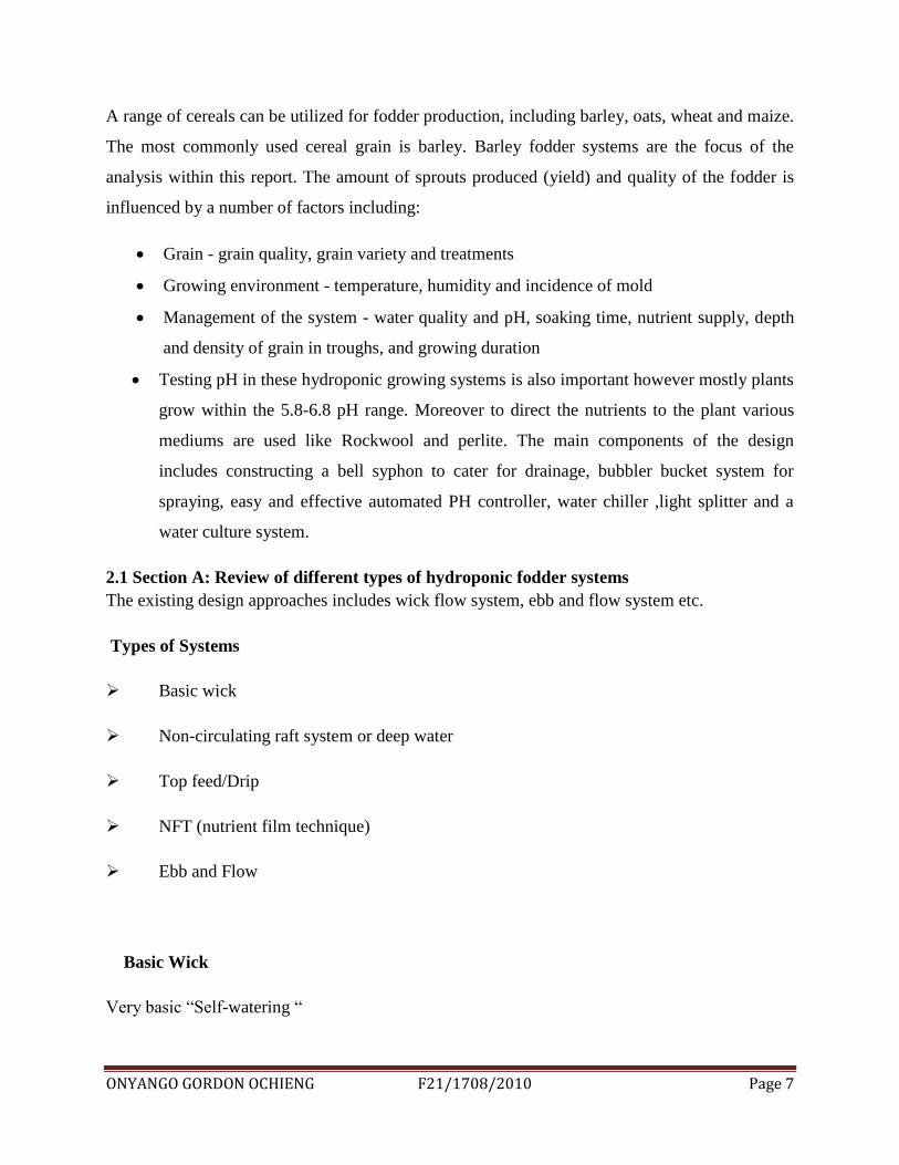
Basic Wick
Very basic “Self-watering “
ONYANGO GORDON OCHIENG F21/1708/2010 Page 8
Figure 2: basic wick system
Source: www.farmtek.com
ONYANGO GORDON OCHIENG F21/1708/2010 Page 9
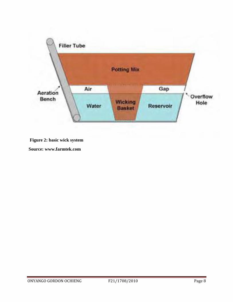
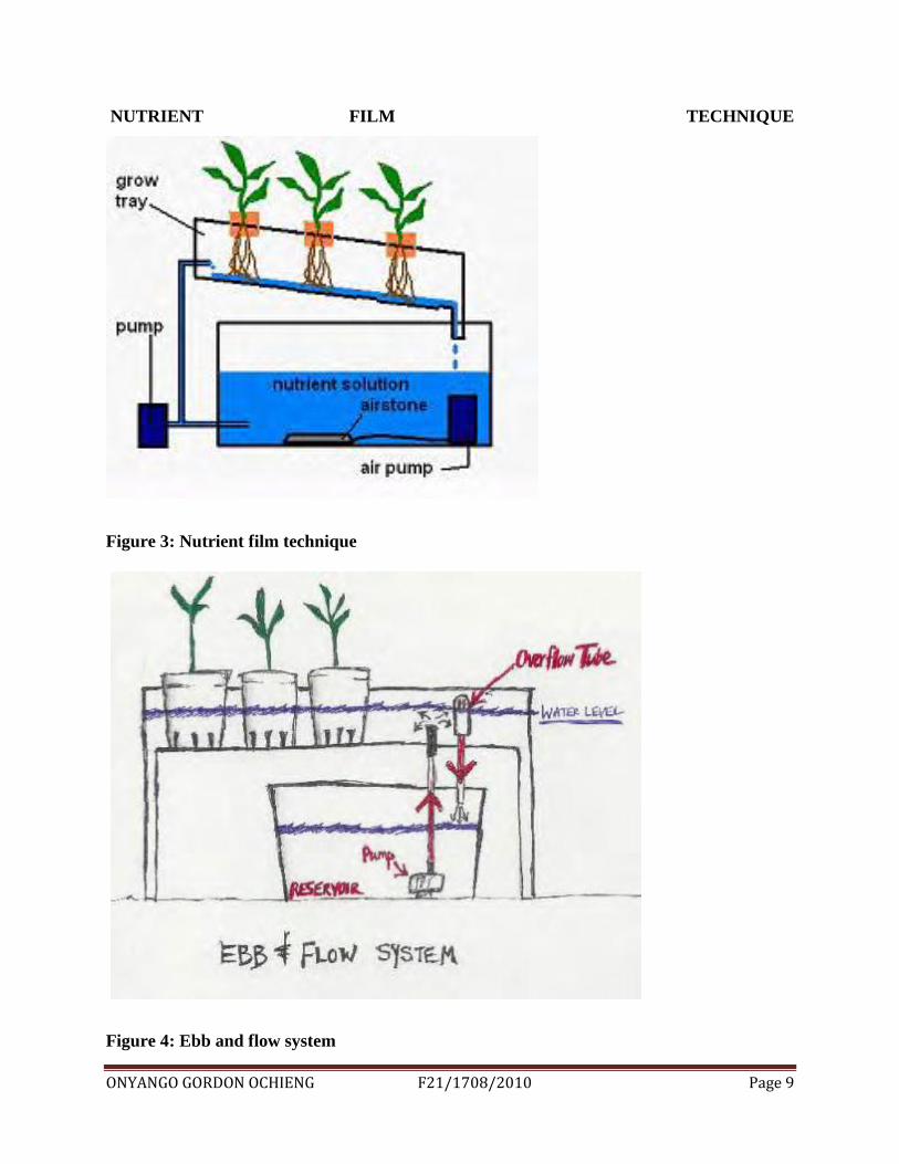
NUTRIENT FILM TECHNIQUE
Figure 3: Nutrient film technique
Figure 4: Ebb and flow system
ONYANGO GORDON OCHIENG F21/1708/2010 Page 10
Non-conventional sources of fodder
The non-conventional methods of obtaining fodder have been developed as a result of efforts to
integrate crop and animal production with benefits to both. The methods that have been tried or
seen to be practical by farmers in the high-potential areas are mainly with maize varieties of the
500 and 600 series. The methods of interest include topping, thinning and defoliation.
Topping involves cutting off the top of the maize plant above the ear. It is known to be practiced
by some farmers in the Central Province of Kenya but definitive scientific data are lacking-.
There are suggestions that maize plants should be topped at 3.5-4.5 months of growth but the
effect of the material so harvested on animal production is not known. It has, however, been
reported that topping reduces grain yield by 15%, a figure which is biologically, socially and
economically substantial.
Thinning is reduction of a high population of maize plants per unit area. The recommended
plant population for the 500 and 600 hybrids is about 44,500 per ha. Farmers who practice
thinning achieve higher plant densities either by closer spacing or by planting more seeds than
the usual two per hole. When plants are knee high, or between 4 and 6 weeks old, the excess
plants are removed and fed to animals. The dry-matter content of thinned maize plants is low
(10 -12%) and this could lead to digestive problems or scouring. Moreover, a farmer would
thin only once, and therefore would have to face the problem of storing a bulky material with
high moisture content.
To defoliate is to deprive a plant of leaves prematurely. With maize, our experience has been
that systematic picking of one leaf per plant once a week produced between 1.0 and 1.2 tonnes of
dry matter per ha in a season. The best times to start plucking the leaves varies from 90 to 120
days post-emergence depending on location, but generally can be said to be about 30 days after
silking. Since a large proportion of maize in Kenya is grown in the high-potential areas,
defoliation is an attractive method of increasing animal resources. The cost of labour involved in
collecting the material is also minimal. In one hour an individual can collect about 7.0 kg dry
matter which can feed six mature sheep in a day.
ONYANGO GORDON OCHIENG F21/1708/2010 Page 11
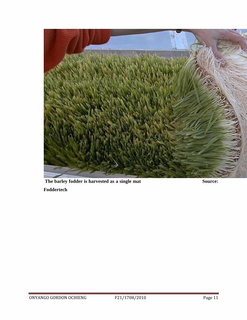
The barley fodder is harvested as a single mat Source:
Foddertech
ONYANGO GORDON OCHIENG F21/1708/2010 Page 12
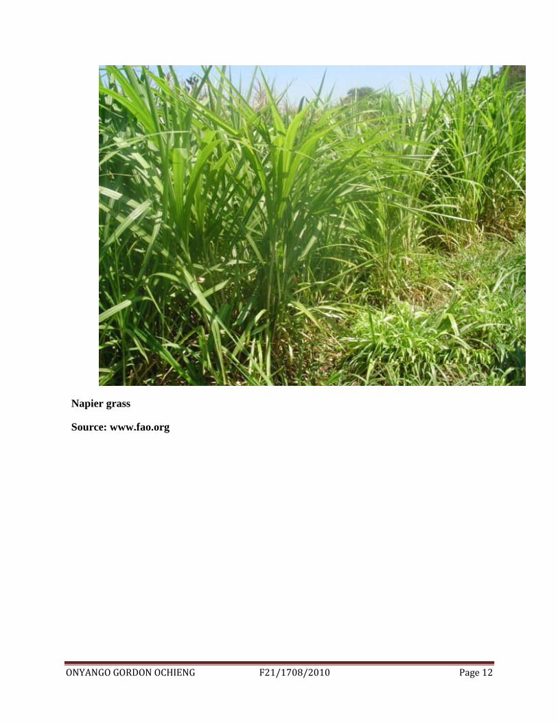
Napier grass
Source: www.fao.org
ONYANGO GORDON OCHIENG F21/1708/2010 Page 13
2.2 ADVANTAGES AND LIMITATIONS OF HYDROPONIC FODDER
Advantages
Crops can be grown where soil is unsuitable
Reduced plant disease
Bigger yields
Reduced Water Usage. The hydroponic system requires a fraction of the water usage of
conventional farming while still supplying high quality stock feed. It takes between 1 to 2 litres
of water to produce one kilo of fodder as compared with 80 – 90 litres of water to grow a kilo of
green grass
Marginal Land Use .This type of fodder production provides huge ecological and
economical advantages, as the production of this lush fodder requires minimal land usage as
compared to field-grown grasses and feeds.
Constant Food Supply. Hydroponic technology has removed the need for long-term
storage of feeds. Unfortunately, Hay, silage and other feeds lose some of their nutritional value
during storage.
Reduced Growth Time the growing time of hydroponic plants takes as little as 7 days
from seed germination to a fully grown plant as at a height of 25 – 30cm ready for harvest
Reduced Labor Requirement This process of growing cattle fodder requires minimal
man-hours per day. Depending on the size of the shed in use, research has shown that as little as
1 hour per day is needed to maintain and produce hydroponic fodder.
Cost effective Studies have concluded that the production of hydroponic fodder is an
extremely cost effective and financially viable.
High Nutritional Value Hydroponic fodder is a highly effective, particularly nutritious
feed, which produces maximum protein and is very rich in vitamins such as B-carotene, trace
elements and enzymes. This fodder is 90 - 95 digestible unlike unsprouted grains, which are at
the best 30% digestible.
Completely natural. An important factor about growing this type of feed is that it is a
completely natural product. The fodder is produced without the use of any hormones, synthetic
growth stimulant or chemical fertilizers, as any fertilizers that are used are totally organic.
ONYANGO GORDON OCHIENG F21/1708/2010 Page 14
Therefore there are no pesticides or fungicides used that could alternately contaminate the meat
or milk that are being produced.
Disadvantages
Initial costs higher
Deeper knowledge is needed
Needs more attention including its high cost of production
Capital, depreciation, labor, running costs), scale of operation,
If introduced, diseases can easily spread
Handling of very high moisture feed and risk of mould which usually occurs in growing fodder
in such uncontrolled, humid, moist environment. Some of the problems that affect the yield
production are mould, bacteria and fungi. However this problem can be combated through –
· Sterilizing the grains surface to eliminate any mould spores on the grain
· Sterilizing all surfaces in the growing area with chlorine or iodine
· Excellent shed ventilation
· The use of sufficient and the correct ratio balance of nutrients in the watering system.
.
ONYANGO GORDON OCHIENG F21/1708/2010 Page 15
3.0 THEORITICAL FRAMEWORK
How hydroponic fodder systems work
The sprouting process
Producing sprouts involves soaking the grain, most commonly barley, in water until fully
saturated, followed by draining and placing it in trays or troughs for sprouting, usually for 5 to 8
days. The grain is kept moist during this period. Pre-soaking is important as there is a rapid
uptake of water which facilitates the metabolism of reserve material and the utilization of these
reserves for growth and development (Thomas and Reddy 1962 as cited in Morgan et al. 1992).
Grain is often soaked or washed with a sterilizing solution to help minimize the risk of mould.
The yield and quality of sprouts produced is influenced by many factors such as soaking time,
Grain quality, grain variety and treatments, temperature, humidity, nutrient supply, depth and
Density of grain in troughs and the incidence of mould. To achieve maximum yield and
nutritional benefits of sprouts the grain should be clean, sound, free from broken or infested
seeds, untreated and viable. Cereal seeds germinate equally well under dark or light conditions
(Whyte 1973, Bartlett 1917 and Miller 1978 as cited in Chavan and Kadam 1989).
3.1Determination of water requirement
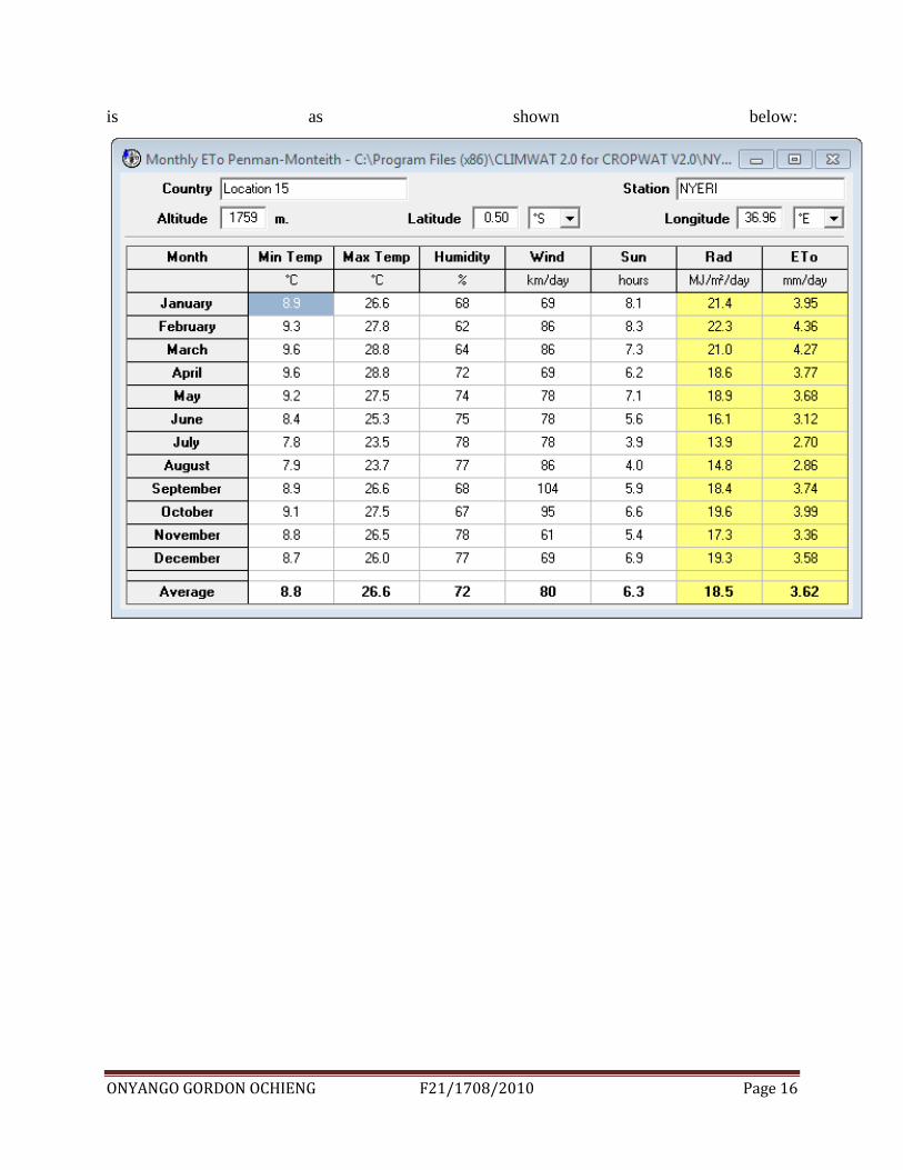
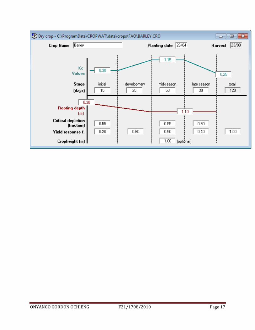
Use the climatic data to determine the reference crop water requirement. Muiga town is based in
Nyeri County the climatic conditions for barley growth according to climwat 2.0 for cropwat 8.0
ONYANGO GORDON OCHIENG F21/1708/2010 Page 16
is as shown below:
ONYANGO GORDON OCHIENG F21/1708/2010 Page 17
ONYANGO GORDON OCHIENG F21/1708/2010 Page 18
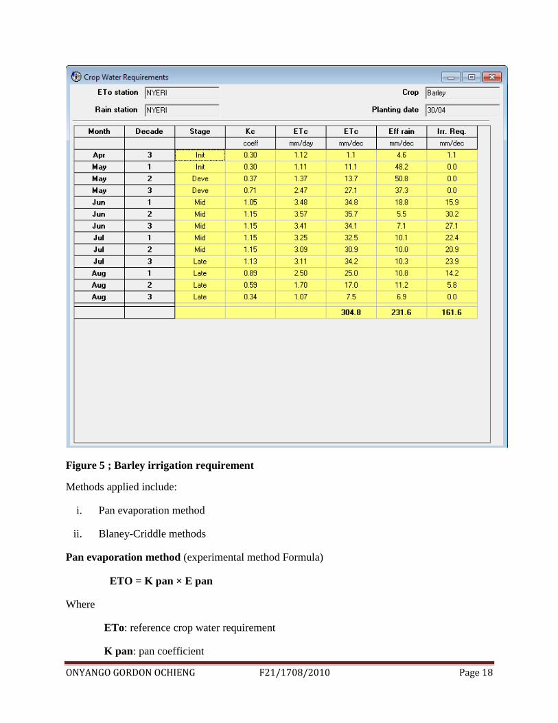
Figure 5 ; Barley irrigation requirement
Methods applied include:
i. Pan evaporation method
ii. Blaney-Criddle methods
Pan evaporation method (experimental method Formula)
ETO = K pan × E pan
Where
ETo: reference crop water requirement
K pan: pan coefficient
ONYANGO GORDON OCHIENG F21/1708/2010 Page 19
E pan: pan evaporation
Blaney – Criddle method (theoretical method using measured climatic data)
ETo = p (0.46 T mean +8)
Where
ETo - Reference crop water requirement (mm/day) as an average for a period of 1 month
T mean - mean daily temperature (°C)
p - mean daily percentage of annual daytime hours
Acquired reference crop water requirement is used to determine crop water requirement by:
ETc = ETo x kc
Where ETc is crop water requirement
ETo is reference crop water requirement
Kc is crop factor
Determination of the total required water per day to be supplied to the crops
Net irrigation requirement
This is the depth of irrigation water necessary to meet crop water requirement of the crop during
a certain period
NIR = ETc – Re
Where NIR is net irrigation requirement [mm/day], ETc is crop water requirement [mm/day]
and Re is effective rainfall [mm/day]
Gross irrigation requirement
It is the Net irrigation requirement of a given crop plus operational losses of the system
determined from the overall system efficiency
GIR =
Where GIR is gross irrigation requirement [mm/day], NIR is net irrigation requirement [mm]
and ηs is system efficiency [%]
ONYANGO GORDON OCHIENG F21/1708/2010 Page 20
Scheme water requirement
This is the total amount of water required to sufficiently irrigate the whole area.
SWR = GIR x A
Where SWR is scheme water requirement, GIR is gross water requirement and A is the total
area covered by the system at ago.
Choice of sprinkler (misters)
The low pressure machines use spray nozzles and therefore have a high instantaneous application
rate and are best suited for mid sprouting fodder. The medium pressure machines use low
pressure impact sprinklers, have a lower instantaneous application rate, and thus can be fixed
while spraying from day 5 of sprouting to maturity period (day 7). Generally sprinklers give an
application rate of between 6 to 9 mm/h which give the highest distribution efficiency.
Qe = GAR x A
Where Qe is sprinkler discharge [m3/h], GAR is gross application rate [mm/h], A is wetted area
[m²]
Gross application rate
The rate at which the water is theoretically applied by the sprinkler to the wetted area. An
application rate higher than the infiltration rate of the soil will result in runoff and inadequate
water replacement.
GAR = Qe / A
Where Qe is sprinkler discharge [m3/h], GAR is gross application rate [mm/h]; A is wetted area
[m²]
Net application rate
It is the rate at which the water is applied to the soil surface by the sprinkler after taking into
account the application efficiency of the system.
NAR = GAR x ηa
Where NAR is net application rate [mm/h], GAR = gross application rate [mm/h], ηa = application efficiency [%]
ONYANGO GORDON OCHIENG F21/1708/2010 Page 21
System capacity
This is the required pumping rate of the irrigation system, according to the maximum number of
sprinklers operating in the system.
Q = Ne x Qe
Where Q = system capacity [m3
/h], Ne = number of sprinklers, Qe = sprinkler discharge [ m3/h]
HYDRAULIC CALCULATION
Calculation of head loss in the main pipe.
The Hazen-Williams formula for calculating head loss in pipes and tubes due to friction can be
expressed as:
Pd = 4.52 q1.8/ (c1.85
dh4.8655
)
Where Pd = pressure drop (psi/ft pipe), q = flow rate (m3/s), dh = inside hydraulic diameter (m),
c = design coefficient determined for the type of pipe or tube - the higher the factor, the smoother
the pipe.
The major head loss for a single pipe or duct can be expressed as:
hmajor_loss = λ (l / dh) (v2 / 2 g) (2)
Where
Hloss = head loss (m, ft)
λ = friction coefficient
l = length of pipe (m)
dh = hydraulic diameter (m)
v = flow velocity (m/s, ft/s)
g = acceleration of gravity (m/s2, ft/s
2)
Darcy Weisbach formula
HL = (F) X (L/D) X (V2/2g)
Where
ONYANGO GORDON OCHIENG F21/1708/2010 Page 22
HL = Total Head Loss
F = Friction factor related to the roughness inside the pipe
L = Length of the pipe
D = Diameter of the pipe
V = Average liquid velocity in the pipe
g = Universal Gravitation Constant (g=32.2 ft/sec)
Hazen William formula
HL/100’ = 0.2083 X (100/C)1.85
X (Q1.85
/D4.8655
HL/100‟ = Head loss per 100 feet of pipe
C = Correction factor to account for pipe roughness
Q = Liquid flow rate in GPM
D = Inside pipe diameter
DESIGN OF A PIPELINE
This includes diameter, pipe material, mainline location, and the location and type of valves and
fittings. It involves hydraulic calculations, basic cost-benefit relationships, and potential pressure
surge evaluations for pipe sizes and velocities selected. Mainline operating pressure measured at
the discharge side of each lateral outlet valve should be within 10 percent of the design lateral
operating pressure.
The ground line and pipe hydraulic grade line (HGL) along the mainline can be plotted for easy
identification of critical pressure locations.
The distance between the ground line and HGL will be the operating pressure at that main line
location.
Design of the mainline
The mainline design problem consists of three distinct elements, namely:
The network layout
The sequencing (or scheduling) of the valves during operation; and
The objectives of the valve sequencing problem are twofold:
a) To minimize the pumping energy required at each irrigation shift.
b) To distribute the flow as widely as possible throughout the network in
Each shift, thereby minimizing the pipe sizes needed in the network
Sizing of the pipes and pumps
ONYANGO GORDON OCHIENG F21/1708/2010 Page 23
The higher the pump Pressure (higher pumping costs), the greater the amount of pressure that
can be lost through friction in the pipes and hence the smaller the diameters (and the cheaper the
cost) of the pipes needed in the network.
Sprinkler system design
Design parameters
The parameters considered for sprinkler irrigation system are;
Maximum daily requirement for peak crop water use
The system application efficiency
Peak use/ efficiency= the depth of water that the irrigation system must achieve
Frequency of irrigation. This is determined by the amount of available water in the root zone is
depleted by 50% by plant consumption; it needs to be replenished by irrigation.
Irrigation duration – the amount of time to irrigate varies with plant water needs during
different stages of growth.
The pumping station- is located near the water source and lifts water making it available under
pressure to the system. The pump is required to overcome elevation differences between the
water source and the field, counteract frictional losses within the system and provide adequate
pressure at the nozzles for good water distribution. A gravity based system uses the potential
energy in the elevation drop to create pressure for its operation.
The mainline-delivers water from the water source to the field. It may either be permanent or
movable.
The lateral pipes – delivers water from the mainline at different sections of the system.
The riser – delivers the water from the lateral pipes to the sprinkler. The length of the riser
depends on the height of the crops under irrigation, although a minimum of 30 cm is
recommended for a good distribution pattern.
The sprinkler –is the unit that sprays the pressurized water through an orifice and rotates to
distribute water throughout the field.
The accessories (e.g. tees and unions) are parts of the system that generally connects all the
units to form a water tight system. These parts are very important to an efficient system and
should be installed whenever possible.
ONYANGO GORDON OCHIENG F21/1708/2010 Page 24
FLOW IN PIPES
Pipes are used to supply water to the sprinkler. Their size, wall thickness and strength depend on
the discharge they must carry and pressure required in the system .it is difficult to design a
system that will provide the right pressure at every sprinkler. Normally, pressure varies
throughout the pipe system as losses occur from friction. Pressures are usually highest at the
head of the system close to the pump and gradually reduce towards the tail.
Pressure
In general terms, pressure is energy required to operate a sprinkler system, more specifically, it is
defined as the force acting uniformly over an area. It is measured in (N/m2) and bars. A typical
operating pressure for a small rotary sprinkler is 3 bars.
Discharge
This is the volume of water flowing along the pipe each second which is measured in cubic
meters per second.
Pipe sizes and safe pressures
The pipes are sized according to how much water can go through it. The interior surface of the
pipe is rough, and this causes frictional loss, which diminishes the amount of pressure available
to operate the heads. By controlling the speed or velocity of water, friction loss can also be
controlled. Larger pipe sizes are more expensive than the smaller sizes. The pipe gets smaller as
it delivers water to irrigation heads. The bigger the flow a pipe must carry the bigger the pipe
must be.
BASIC HYDRAULICS
Water pressure
Pressure is what forces water to flow through the pipes to the sprinklers. This pressure is often
created by the waters own weight .water pressure is a force at a particular location caused by
weight of water above that location.
Static water pressure
This is calculated when water is standing still. When water is not moving you need only to
calculate the pressure in the pipe caused by elevation or by a pump.
ONYANGO GORDON OCHIENG F21/1708/2010 Page 25
Working (dynamic) pressure
This is the pressure exerted by water moving and flowing. When water starts moving through a
pipe, it begins to lose power or pressure. The roughness of the pipe walls slows the molecules of
water as they rush by.
Flow characteristics
Frictional losses –it is the loss of pressure as water moves. As water moves through the inside
of a pipe, the roughness of the pipe wall slows the water, especially over long runs of pipe or
when water is travelling very fast.
Velocity – this defines the rate at which water is moving and expressed in meters per second.
The maximum recommended velocity of water travelling through a pipe for irrigation is 2m/s.
when water moves faster, then turbulence in the pipe and this will cause major problems in the
pipe.
Hydraulics of pipe flow
According to Bernoulli‟s equation the total energy or head at any point in a pipe is made up of
four components.
The pressure head = P
The velocity head =V
The head due to topographic elevation= Z
Frictional head loss= hf
Therefore the energy, E, at a given point is given by;
E=
Where
P- Pressure in kj/m2
α- weight of a unit volume of water in kg/m2
g- Acceleration due to gravity
V- Velocity
ONYANGO GORDON OCHIENG F21/1708/2010 Page 26
Loss of head due to friction in pipe
Loss of head due to friction in a pipe between two points at a distance 1 meter apart is given by;
Hf =
In which
F= coefficient of friction or a pipe.
l- Length of pipe
d= diameter of pipe, m
Head loss in sprinkler laterals
A general formula for pressure loss is given by;
hf =
This formula is for lateral with a number of specially spaced sprinklers. Where
K= friction factor
L= length of pipe
Q= total flow in the laterals
D = diameter of the pipes
Hf is read from the designers tables and it varies with the number of outlets.
Discharge and pressure relations in laterals
Friction loss depends upon the flow in the pipes while the flow depends upon the flow discharge
of individual sprinklers. Sprinkler discharge is a function of the pressure at the individual
sprinkler.
Q=k
Where
Q= sprinkler nozzle discharge
P= pressure at the sprinkler
ONYANGO GORDON OCHIENG F21/1708/2010 Page 27
K= nozzle discharge coefficient
The discharge ratio is the ratio of discharge of any sprinkler on the lateral to the discharge of any
of the sprinklers.
PUMP SELECTION
In order to maintain flow, energy must be supplied to the pipe system. The energy is provided by
a pump to counter the energy losses in pipe system, and overcome energy due to elevation
differences.
If we consider two points at a and b at different elevations then the total energy required for the
flow from point a to b to be maintained is given by;
E= ZB+ZA+KQ2
Where
ZB=elevation of b from a
ZB= elevation from the datum
K= coefficient representing all resistance coefficients along the pipes
Q= discharge
The above equation is known as the system characteristics and the term Δz is the static lift.
The loss term KQ2 incorporates the following losses;
1. Pump suction losses + friction loss in the section pipe= separation loss
2. All the separation and frictional losses on the delivery side of the pump
The pump discharge should meet the peak demand of water for the selected cropping pattern.
The rate of pumping depends on the area of land under the crop, the water requirements, rotation
period, duration for which the pump is operated each day. It can be computed with the following
relationship.
Q=
Where
Q= rate of discharge, liters/sec
ONYANGO GORDON OCHIENG F21/1708/2010 Page 28
A= area of land under crops, hectares
Y= depth of irrigation, cm
R= Rotation period, days
T= duration of pumping, hours per day
Nozzles
A nozzle is a mechanical device designed to control the characteristics of a fluid as it exists from
an enclosed chamber into some medium. They are frequently used to control the rate of flow,
direction and/or the pressure of the stream that emerges from them. Misting systems use nozzles
to emit fine droplets of water at high pressure. Convergent nozzles accelerate fluids while
divergent nozzles slow fluids
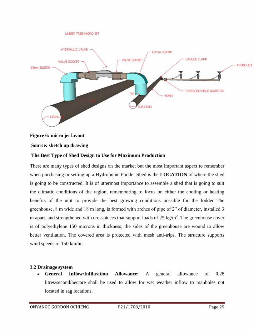
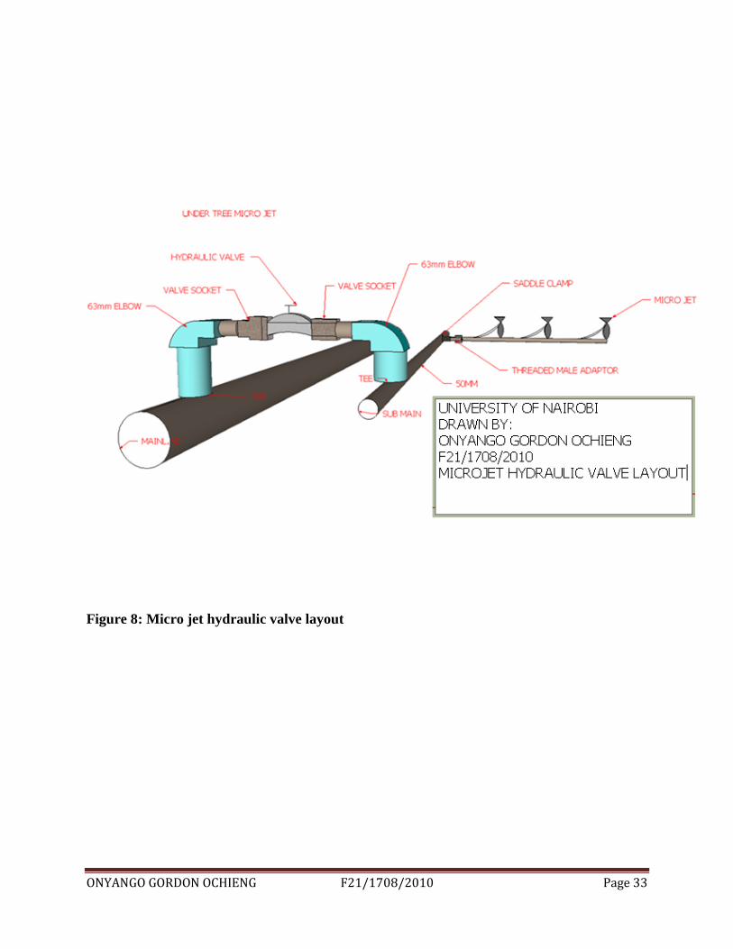
Micro jets consist of laterals lines and sub mains. The connection consists of saddle clamp, male
adaptor, reducer bush, elbow, PE pipe, PVC end cap, PVC pipe, PE connectors; end lines
The medium-range mini-sprinkler is a great choice for, greenhouses, and vegetable crops. With a
wide range of configurable features and flexible installation options, it can deliver the spray
pattern that's right for the fodder. It delivers gentle droplets and a consistent spray pattern while
inverted in greenhouses. The spray pattern size is moderate to wide and can be used for spacing
of up to 7.5 meters by 7.5 meters. As an additional feature, Rondo is designed to be easily
disassembled, allowing for both field maintenance and replacement of individual parts. It is
available with optional features including an anti-insect snap-fit t cup and numerous deflector
plates, providing added protection and specialized spray patterns.
Specifications are
Flow rates: 30-300 lph
Recommended operation pressure: 1.5-2.5 bar
Versatility - a wide choice of models and applications: Single or double bridge frame, Installed
in upright or inverted position, 11 color-coded nozzle sizes3 assembly options with bayonet-
mount nozzles: 3/8” THM x conic female inlet - accommodates Meteor adaptors or threaded
hammer stakes.
ONYANGO GORDON OCHIENG F21/1708/2010 Page 29
Figure 6: micro jet layout
Source: sketch up drawing
The Best Type of Shed Design to Use for Maximum Production
There are many types of shed designs on the market but the most important aspect to remember
when purchasing or setting up a Hydroponic Fodder Shed is the LOCATION of where the shed
is going to be constructed. It is of uttermost importance to assemble a shed that is going to suit
the climatic conditions of the region, remembering to focus on either the cooling or heating
benefits of the unit to provide the best growing conditions possible for the fodder The
greenhouse, 8 m wide and 18 m long, is formed with arches of pipe of 2” of diameter, installed 3
m apart, and strengthened with crosspieces that support loads of 25 kg/m2. The greenhouse cover
is of polyethylene 150 microns in thickness; the sides of the greenhouse are wound to allow
better ventilation. The covered area is protected with mesh anti-trips. The structure supports
wind speeds of 150 km/hr.
3.2 Drainage system
General Inflow/Infiltration Allowance: A general allowance of 0.28
litres/second/hectare shall be used to allow for wet weather inflow to manholes not
located in sag locations.
ONYANGO GORDON OCHIENG F21/1708/2010 Page 30
Inflow Allowance for Manholes in Sag Locations: For manholes located in sag
locations where ponding will occur or low areas subject to inundation, an inflow
allowance of 0.4 litres/second shall be made for each manhole.
Minimum Slopes: All sanitary sewers should be designed with a minimum slope of
0.4% or greater. Where it is not practical to do so, the following minimum slopes will be
permitted for various sewer sizes:
Sewer Size (mm) Minimum Slope (%)
200 0.40
250 0.28
300 0.22
375 0.15
450 0.12
≥525 0.10
Velocity: The velocity of flow in sanitary sewers shall be kept between 0.6
metres/second and 3.0 metres/second.
Depth: Sanitary mains shall have depth adequate to permit sewer services to be
constructed a minimum of 2.74 m deep (from the ground surface to the invert of the pipe)
at the property line separating private and city land.
Manhole: Manholes must be installed at the end of each sewer, at all changes in sewer
size, grade, or alignment and at all junctions. The maximum permitted manhole spacing
for all sewers less than 1200 mm in diameter is 150 metres.
Pipe Materials: Approved materials for pipe construction of sanitary sewer mains are
non-reinforced concrete pipe, reinforced concrete pipe, and PVC (polyvinyl chloride)
pipe Ultra Nozzle - with either 5mm threaded inlet (flow rates up to 200 lph) or conic
female inlet, mounted on spiked plastic stakes or 8 mm metal rods .
ONYANGO GORDON OCHIENG F21/1708/2010 Page 31
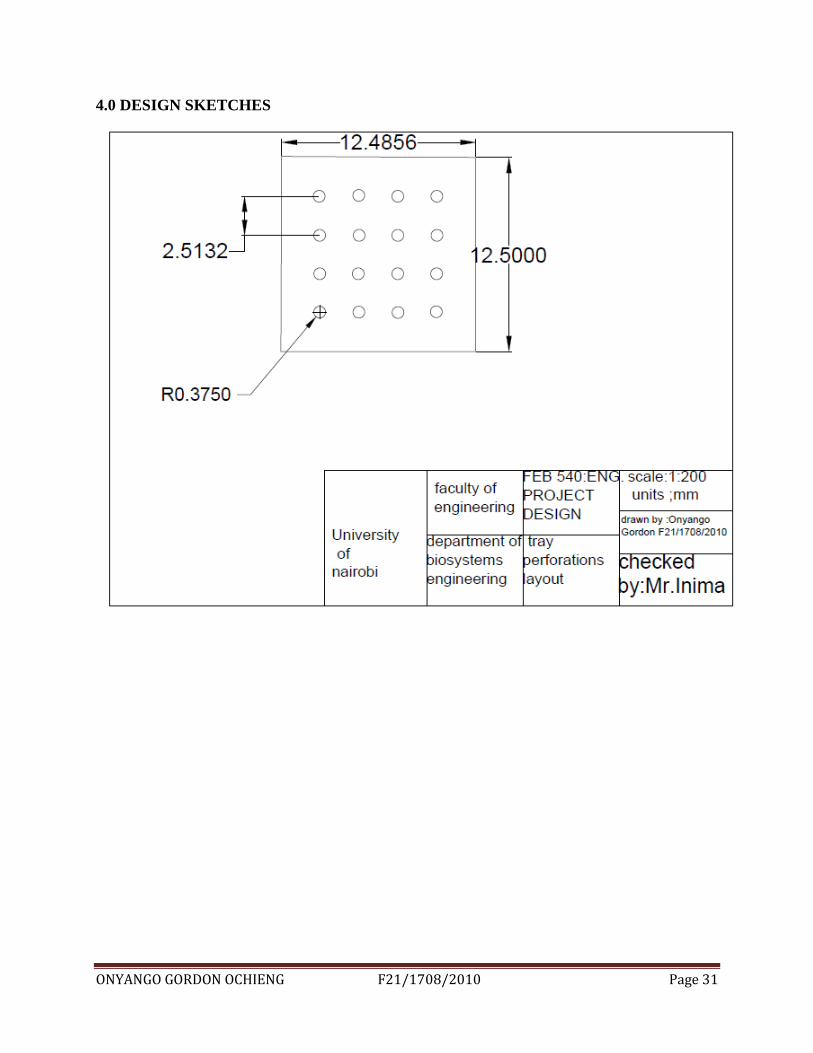
4.0 DESIGN SKETCHES
ONYANGO GORDON OCHIENG F21/1708/2010 Page 32
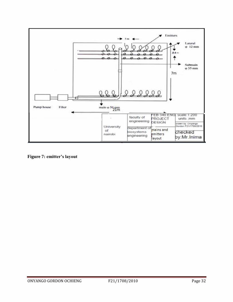
Figure 7: emitter’s layout
ONYANGO GORDON OCHIENG F21/1708/2010 Page 33
Figure 8: Micro jet hydraulic valve layout
ONYANGO GORDON OCHIENG F21/1708/2010 Page 34
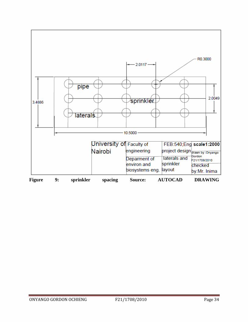
Figure 9: sprinkler spacing Source: AUTOCAD DRAWING
ONYANGO GORDON OCHIENG F21/1708/2010 Page 35
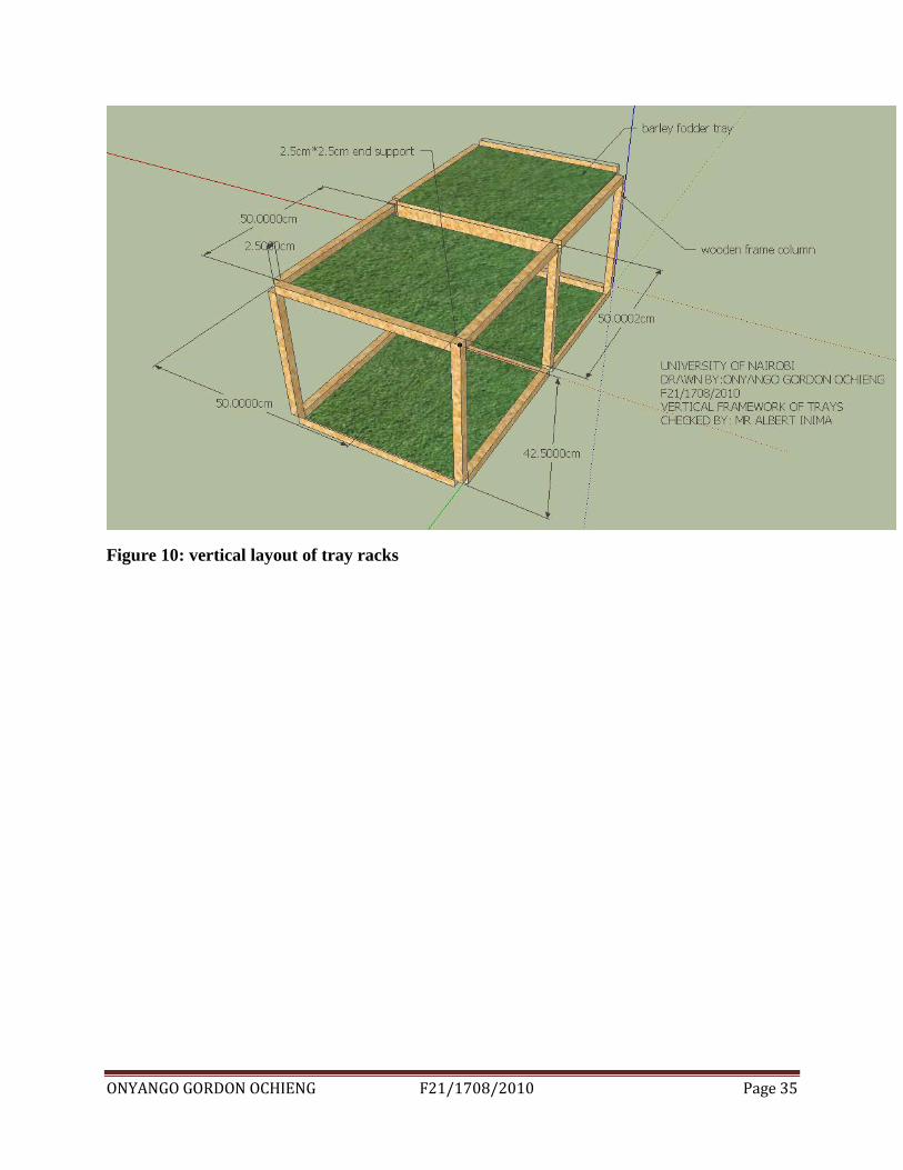
Figure 10: vertical layout of tray racks
ONYANGO GORDON OCHIENG F21/1708/2010 Page 36
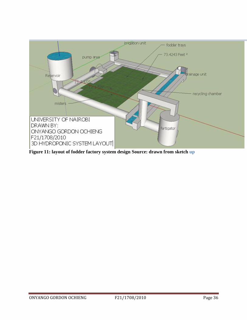
Figure 11: layout of fodder factory system design Source: drawn from sketch up
ONYANGO GORDON OCHIENG F21/1708/2010 Page 37
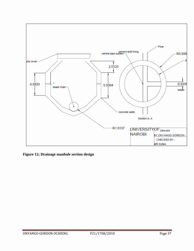
Figure 12; Drainage manhole section design
ONYANGO GORDON OCHIENG F21/1708/2010 Page 38
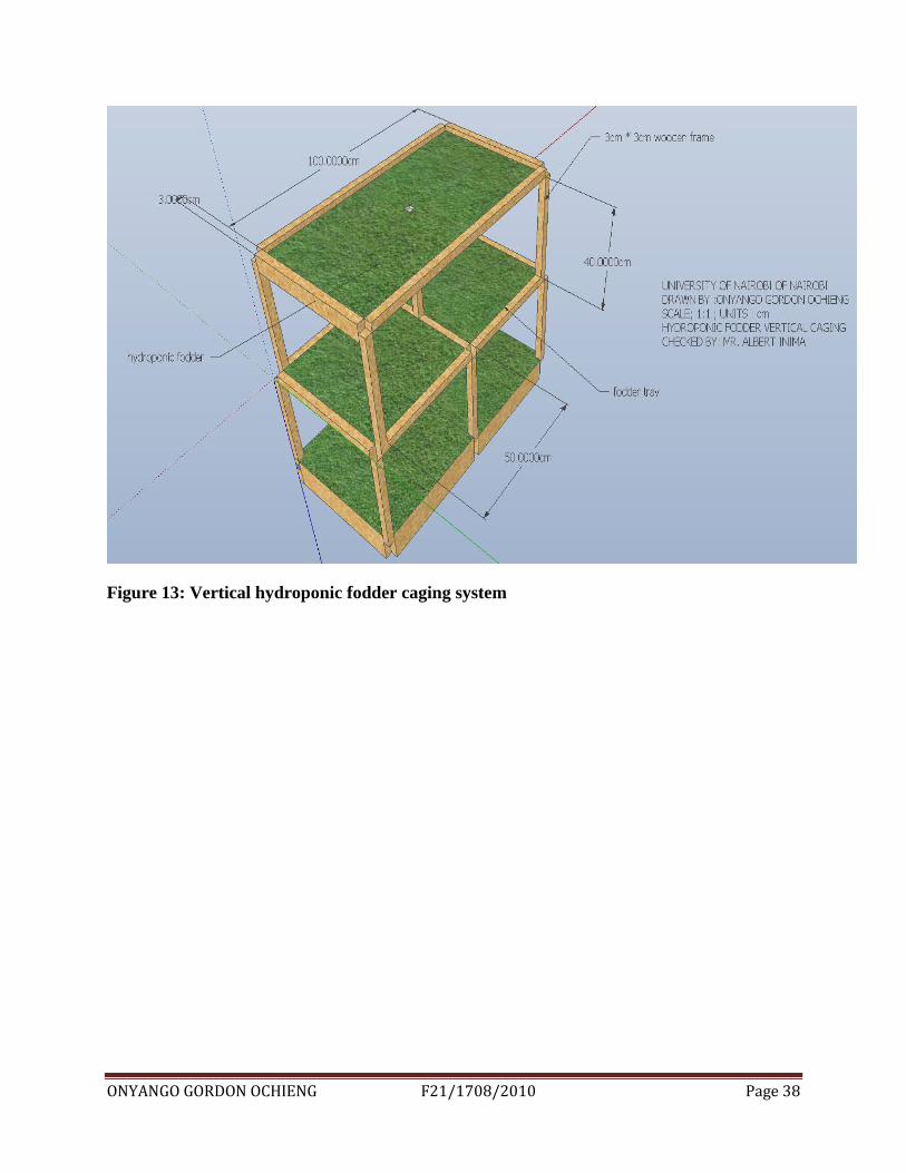
Figure 13: Vertical hydroponic fodder caging system
ONYANGO GORDON OCHIENG F21/1708/2010 Page 39
5.0 METHODOLOGY
Sizing of the system parameters
5.1 Irrigation system (overhead irrigation system)
Selection of the misters
After careful analysis of the data collected (crop water requirement, net irrigation requirement,
and conveyance efficiency) appropriate misters will be selected with sufficient discharge and
pressure to provide the required cooling and humidity at different times of the day.
The engineering principles used at this stage will involve psychometrics and nozzles. Head
control: This consists of a supply line (rigid PVC, or threaded galvanized steel) installed
horizontally at a minimum height of 60 cm above ground. It is equipped with an air release
valve, a check valve, and two -in hose outlets for connection with the fertilizer injector, a shut-
off valve between the two outlets, a fertilizer injector and a filter. Where a gravel filter or a hydro
cyclone sand separator is needed, it is installed at the beginning of the unit complex.
Main pipeline: It is the largest diameter pipeline of the network, capable of conveying the flow
of the system under favorable hydraulic conditions of flow velocity and friction losses.
Sub mains: These are smaller diameter pipelines which extend from the main lines and to which
the system flow is diverted for distribution to the various plots. The pipes are the same kind as
the mains.
Off take hydrants: These are fitted on the sub mains or the mains and equipped with a 2-3-in
shut-off valve. They deliver the whole or part of the flow to the manifolds (feeder lines).
Manifolds (feeder lines): These are pipelines of a smaller diameter than the sub mains and are
connected to the hydrants and laid, usually on the surface, along the plot edges to feed the
laterals. They can be of any kind of pipe available (usually HDPE) in sizes of 2-3 in.
Laterals (irrigating lines): These are the smallest diameter pipelines of the system. They are
fitted to the manifolds, perpendicular to them, at fixed positions, laid along the plants rows and
equipped with water emitters at fixed frequent spacing‟s.
Laterals and pipe sizing
ONYANGO GORDON OCHIENG F21/1708/2010 Page 40
Depending on the discharge required at the misters and the number of misters, the appropriate
size of the pipes will be designed using the Darcy Weisbach equations as well as the pipe class
depending on the mister‟s pressure.
Emitters: A water emitter for irrigation is a device of any kind, type and size which, fitted on a
pipe, is operated under pressure to discharge water in any form: by shooting water jets into the
air (sprinklers), by small spray or mist (sprayers), by continuous drops (drippers), by small
stream or fountain (bubblers, gates and openings on pipes, small diameter hoses),
Storage tank (external reservoir design)
The storage tank will be designed according to the amount of discharge required at the misters
and the estimated misting schedule in accordance to the temperature and humidity control system
for the greenhouse.
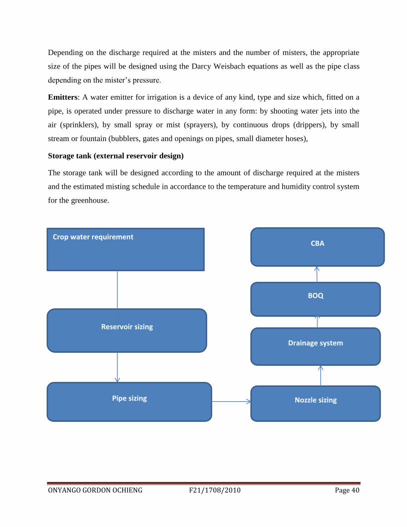
Crop water requirement
Reservoir sizing
Pipe sizing Nozzle sizing
Drainage system
BOQ
CBA
ONYANGO GORDON OCHIENG F21/1708/2010 Page 41
5.2 Quality of space
Fodder-hydroponic system: - The hydroponic system consists of the following parts: frame,
growth trays and aeration, lighting, cooling, irrigation, supernatant collection and control units.
Frame: - The frame was constructed of aluminum angles with a length of 125 cm, a width of 36
cm and a height of 42.5 cm. The frame supported the growth trays and all other systems.
Plant growth unit: - The plant growth unit consisted of trays. Each tray was made of foam with
dimensions of 50 x 50 x 10 cm. The bottom of trays was perforated with 1.5 mm-diameter holes
diameter and spacing of 20 mm. The plant supporting trays were positioned in the troughs so that
the plant roots were in contact with the liquid. The placement of trays was maintained by means
of supports with dimensions of 2.5 x 2.5 x 2.5 cm and stuck below the corners of each tray.
Supplementary irrigation unit: -
The recycled water application unit consisted of the following parts:
• A water storage tank for storing the water and nutrient
A submersible pump transfers the water from the storage tank to the irrigation system. The pump
is connected to the irrigation system using external tubing.
A valve, to control the amount of water fed to mini-sprinklers and, for applying the water into
the plant supporting trays.
Drainage unit:
The drainage unit consists of collecting bin stuck under the plant trays. The water exit out the bin
to storage tank by tube with adequate diameter. The ground drainage system consists of a sewer
main, cover, branch sewer and the walls r lined with cement grout.
The sewer size determines the slope of the flow as used in the design and shown in
(appendices……..)
Reservoir capacity
Volume of water to be stored in the reservoir is determined from the irrigation water requirement
As a safety factor, the reservoir is made 20% larger than required. Therefore:
120/100 volume of water= required volume to be stored.
The volume is then used to determine the dimensions of the reservoir

ONYANGO GORDON OCHIENG F21/1708/2010 Page 42
DATA REQUIRED FOR THE DESIGN PROJECT
Crop water requirement (irrigation schedule, area covered, crop type)
Number of animals per unit
Reservoir sizing(head , length, width)
Pipe ( length, diameter)
Pump (flow rate, differential head)
Drainage system( manhole elevation
ONYANGO GORDON OCHIENG F21/1708/2010 Page 43
6.0 RESULTS AND ANALYSIS
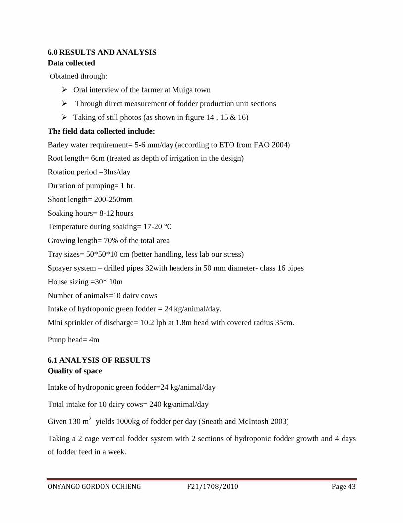
Data collected
Obtained through:
Oral interview of the farmer at Muiga town
Through direct measurement of fodder production unit sections
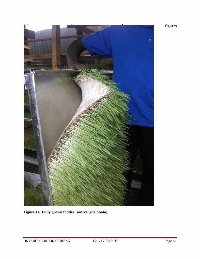
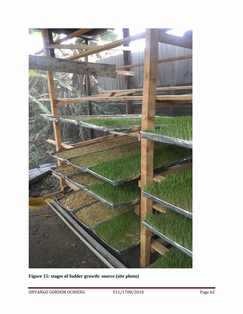
Taking of still photos (as shown in figure 14 , 15 & 16)
The field data collected include:
Barley water requirement= 5-6 mm/day (according to ETO from FAO 2004)
Root length= 6cm (treated as depth of irrigation in the design)
Rotation period =3hrs/day
Duration of pumping= 1 hr.
Shoot length= 200-250mm
Soaking hours= 8-12 hours
Temperature during soaking= 17-20
Growing length= 70% of the total area
Tray sizes= 50*50*10 cm (better handling, less lab our stress)
Sprayer system – drilled pipes 32with headers in 50 mm diameter- class 16 pipes
House sizing =30* 10m
Number of animals=10 dairy cows
Intake of hydroponic green fodder = 24 kg/animal/day.
Mini sprinkler of discharge= 10.2 lph at 1.8m head with covered radius 35cm.
Pump head= 4m
6.1 ANALYSIS OF RESULTS
Quality of space
Intake of hydroponic green fodder=24 kg/animal/day
Total intake for 10 dairy cows= 240 kg/animal/day
Given 130 m2
yields 1000kg of fodder per day (Sneath and McIntosh 2003)
Taking a 2 cage vertical fodder system with 2 sections of hydroponic fodder growth and 4 days
of fodder feed in a week.
ONYANGO GORDON OCHIENG F21/1708/2010 Page 44
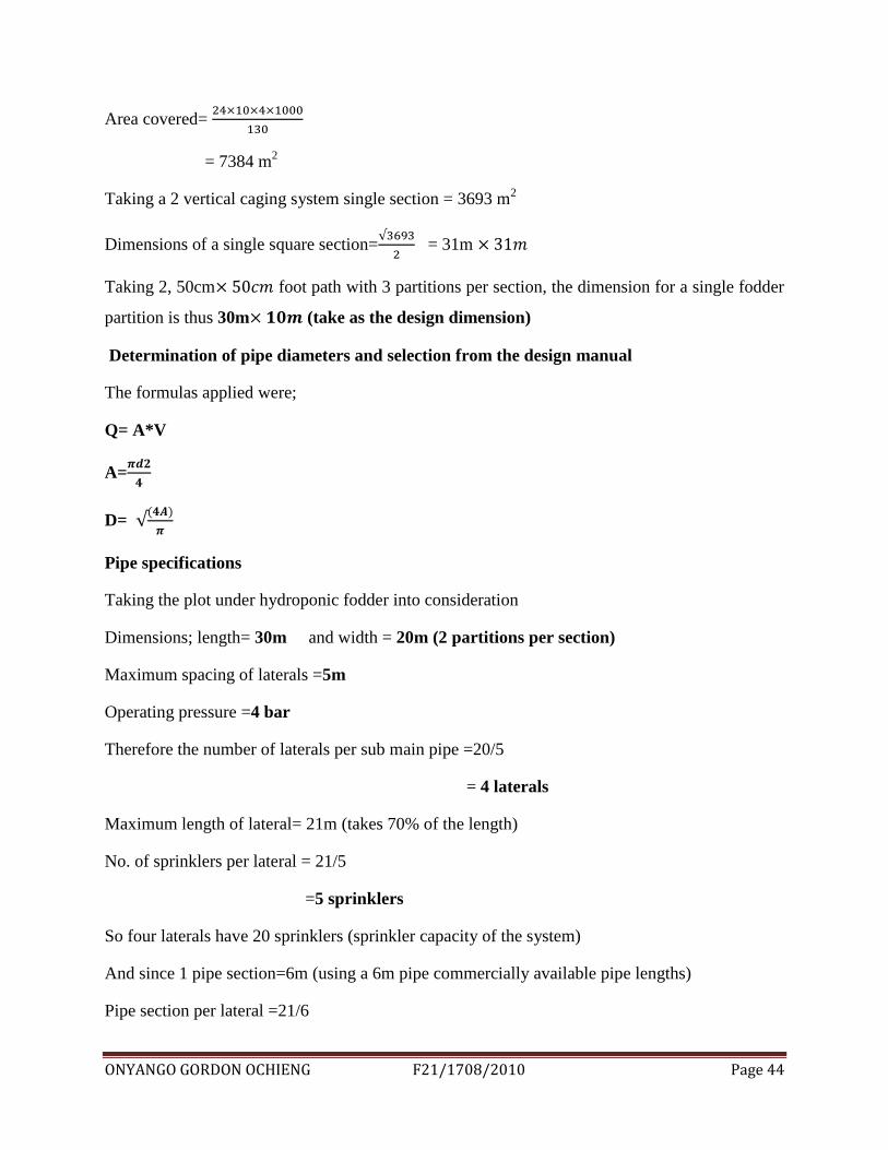
Area covered=
= 7384 m2
Taking a 2 vertical caging system single section = 3693 m2
Dimensions of a single square section=
= 31m
Taking 2, 50cm foot path with 3 partitions per section, the dimension for a single fodder
partition is thus 30m (take as the design dimension)
Determination of pipe diameters and selection from the design manual
The formulas applied were;
Q= A*V
A=
D=
Pipe specifications
Taking the plot under hydroponic fodder into consideration
Dimensions; length= 30m and width = 20m (2 partitions per section)
Maximum spacing of laterals =5m
Operating pressure =4 bar
Therefore the number of laterals per sub main pipe =20/5
= 4 laterals
Maximum length of lateral= 21m (takes 70% of the length)
No. of sprinklers per lateral = 21/5
=5 sprinklers
So four laterals have 20 sprinklers (sprinkler capacity of the system)
And since 1 pipe section=6m (using a 6m pipe commercially available pipe lengths)
Pipe section per lateral =21/6
ONYANGO GORDON OCHIENG F21/1708/2010 Page 45
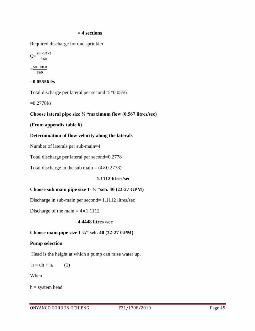
= 4 sections
Required discharge for one sprinkler
Q=
=
=0.05556 l/s
Total discharge per lateral per second=5*0.0556
=0.2778l/s
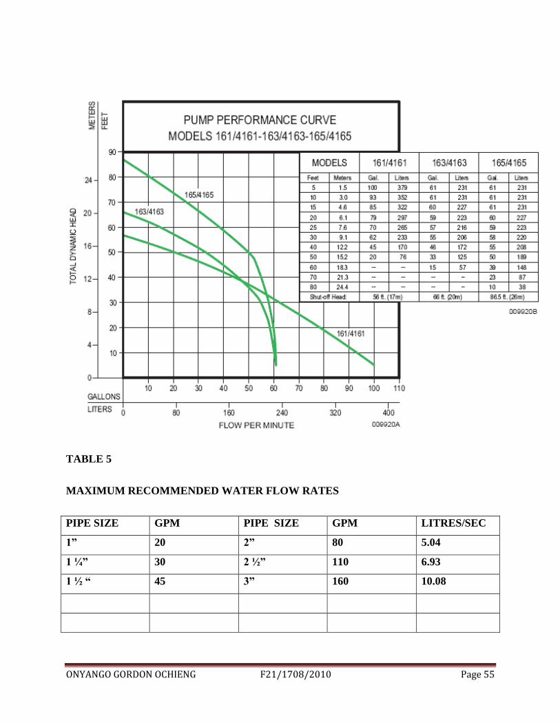
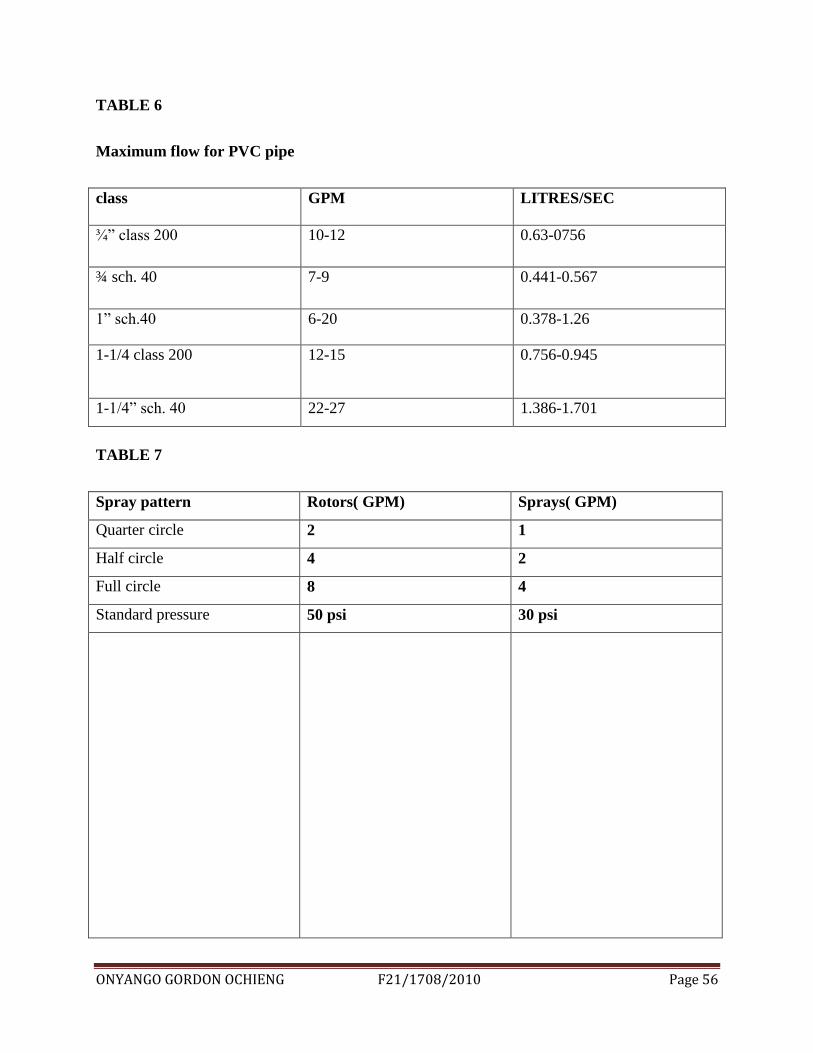
Choose lateral pipe size ¾ “maximum flow (0.567 litres/sec)
(From appendix table 6)
Determination of flow velocity along the laterals
Number of laterals per sub-main=4
Total discharge per lateral per second=0.2778
Total discharge in the sub main = (4 0.2778)
=1.1112 litres/sec
Choose sub main pipe size 1- ¼ “sch. 40 (22-27 GPM)
Discharge in sub-main per second= 1.1112 litres/sec
Discharge of the main = 4 1.1112
= 4.4448 litres /sec
Choose main pipe size 1 ¼” sch. 40 (22-27 GPM)
Pump selection
Head is the height at which a pump can raise water up.
h = dh + hl (1)
Where
h = system head
ONYANGO GORDON OCHIENG F21/1708/2010 Page 46
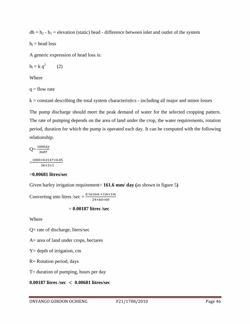
dh = h2 - h1 = elevation (static) head - difference between inlet and outlet of the system
hl = head loss
A generic expression of head loss is:
hl = k q2 (2)
Where
q = flow rate
k = constant describing the total system characteristics - including all major and minor losses
The pump discharge should meet the peak demand of water for the selected cropping pattern.
The rate of pumping depends on the area of land under the crop, the water requirements, rotation
period, duration for which the pump is operated each day. It can be computed with the following
relationship.
Q=
=
=0.00681 litres/sec
Given barley irrigation requirement= 161.6 mm/ day (as shown in figure 5)
Converting into litres /sec =
= 0.00187 litres /sec
Where
Q= rate of discharge, liters/sec
A= area of land under crops, hectares
Y= depth of irrigation, cm
R= Rotation period, days
T= duration of pumping, hours per day
0.00187 litres /sec 0.00681 litres/sec
ONYANGO GORDON OCHIENG F21/1708/2010 Page 47
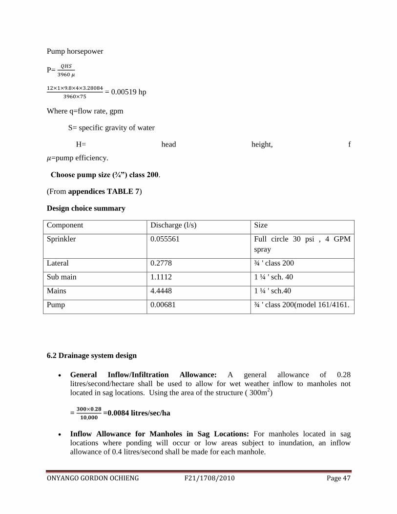
Pump horsepower
P=
= 0.00519 hp
Where q=flow rate, gpm
S= specific gravity of water
H= head height, f
=pump efficiency.
Choose pump size (¾”) class 200.
(From appendices TABLE 7)
Design choice summary
Component Discharge (l/s) Size
Sprinkler 0.055561 Full circle 30 psi , 4 GPM
spray
Lateral 0.2778 ¾ ' class 200
Sub main 1.1112 1 ¼ ' sch. 40
Mains 4.4448 1 ¼ ' sch.40
Pump 0.00681 ¾ ' class 200(model 161/4161.
6.2 Drainage system design
General Inflow/Infiltration Allowance: A general allowance of 0.28
litres/second/hectare shall be used to allow for wet weather inflow to manholes not
located in sag locations. Using the area of the structure ( 300m2)
=
=0.0084 litres/sec/ha
Inflow Allowance for Manholes in Sag Locations: For manholes located in sag
locations where ponding will occur or low areas subject to inundation, an inflow
allowance of 0.4 litres/second shall be made for each manhole.
ONYANGO GORDON OCHIENG F21/1708/2010 Page 48
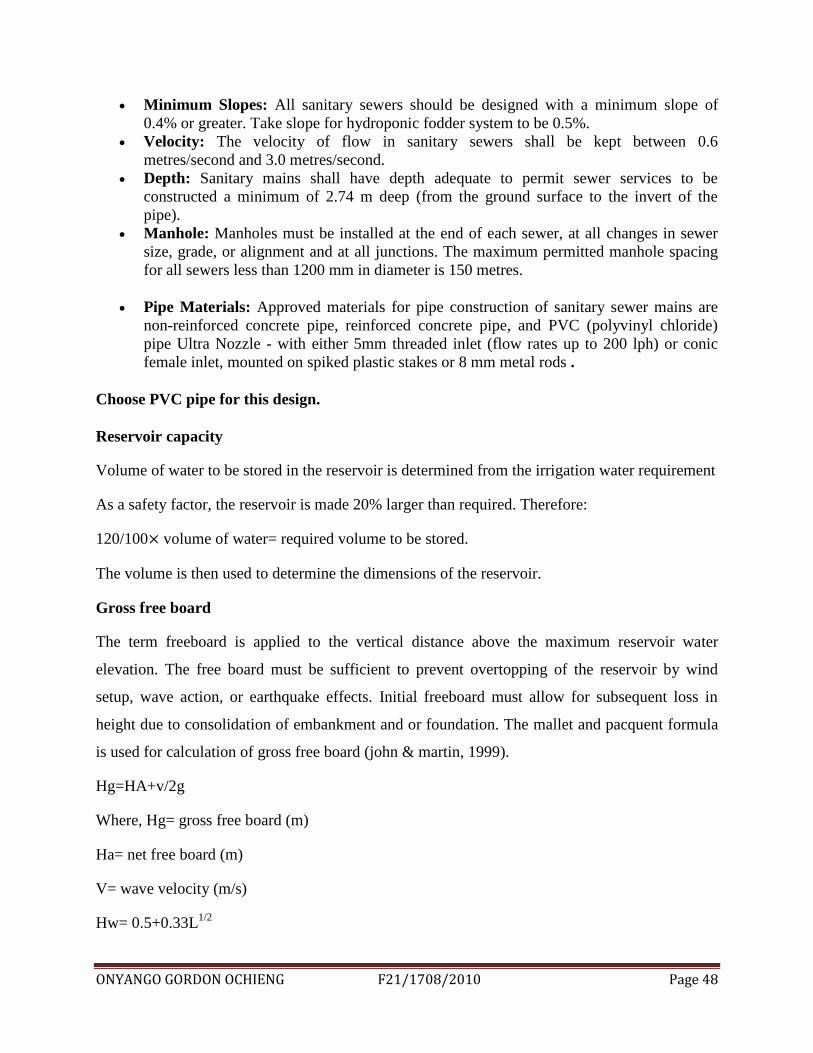
Minimum Slopes: All sanitary sewers should be designed with a minimum slope of
0.4% or greater. Take slope for hydroponic fodder system to be 0.5%.
Velocity: The velocity of flow in sanitary sewers shall be kept between 0.6
metres/second and 3.0 metres/second.
Depth: Sanitary mains shall have depth adequate to permit sewer services to be
constructed a minimum of 2.74 m deep (from the ground surface to the invert of the
pipe).
Manhole: Manholes must be installed at the end of each sewer, at all changes in sewer
size, grade, or alignment and at all junctions. The maximum permitted manhole spacing
for all sewers less than 1200 mm in diameter is 150 metres.
Pipe Materials: Approved materials for pipe construction of sanitary sewer mains are
non-reinforced concrete pipe, reinforced concrete pipe, and PVC (polyvinyl chloride)
pipe Ultra Nozzle - with either 5mm threaded inlet (flow rates up to 200 lph) or conic
female inlet, mounted on spiked plastic stakes or 8 mm metal rods .
Choose PVC pipe for this design.
Reservoir capacity
Volume of water to be stored in the reservoir is determined from the irrigation water requirement
As a safety factor, the reservoir is made 20% larger than required. Therefore:
120/100 volume of water= required volume to be stored.
The volume is then used to determine the dimensions of the reservoir.
Gross free board
The term freeboard is applied to the vertical distance above the maximum reservoir water
elevation. The free board must be sufficient to prevent overtopping of the reservoir by wind
setup, wave action, or earthquake effects. Initial freeboard must allow for subsequent loss in
height due to consolidation of embankment and or foundation. The mallet and pacquent formula
is used for calculation of gross free board (john & martin, 1999).
Hg=HA+v/2g
Where, Hg= gross free board (m)
Ha= net free board (m)
V= wave velocity (m/s)
Hw= 0.5+0.33L1/2
ONYANGO GORDON OCHIENG F21/1708/2010 Page 49
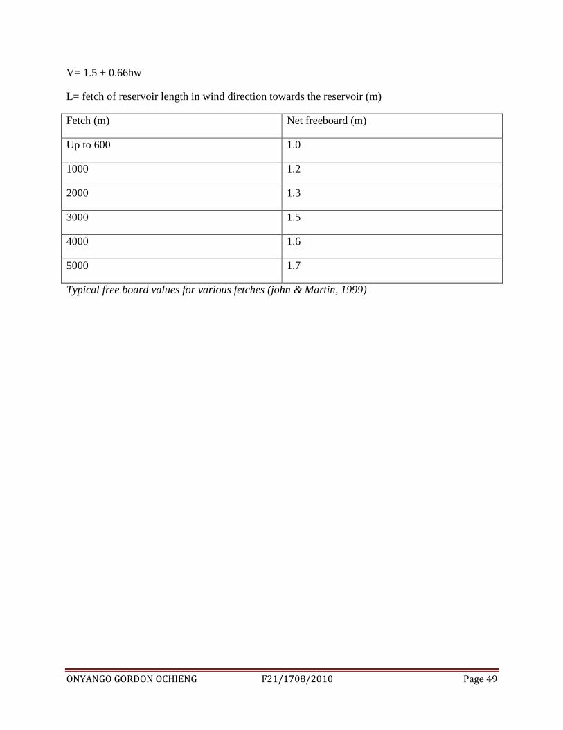
V= 1.5 + 0.66hw
L= fetch of reservoir length in wind direction towards the reservoir (m)
Fetch (m) Net freeboard (m)
Up to 600 1.0
1000 1.2
2000 1.3
3000 1.5
4000 1.6
5000 1.7
Typical free board values for various fetches (john & Martin, 1999)

ONYANGO GORDON OCHIENG F21/1708/2010 Page 50
7.0 CONCLUSSION AND RECOMMENDATION
This chapter will conclude this design report, detail the status of the project at present, and make
recommendations for future work that would benefit the project.
7.1 CONCLUSION
This project has dealt with the feasibility and design of hydroponic fodder factory at Muiga
town. The desire to design a vertical caging system for fodder trays, drainage system, and
overhead irrigation system has been the key factors in this design project.
The component spacing was found to be 30
Structural space took 70% of the total area = 21
Maximum spacing of laterals = 5m
Lateral pipe size ¾ „‟ maximum flow 0.567litres/sec
Sub main pipe 1 ¼‟‟ sch.40 (22-27 GPM)
Main pipe size 1 ¼‟‟ sch.40 (22-27 GPM)
Pump 3 ¼ „‟ class 200, 0.00519 horsepower, model 161/4161.
Drainage system design was such that the infiltration allowance was 0.0084 litres/sec
Minimum slope was determined to be 0.4% with manhole dimension (height 12cm, sewer main
diameter= 15cm)

ONYANGO GORDON OCHIENG F21/1708/2010 Page 51
7.2 RECCOMMENDATION
The development of this design project was quite successful and for this reason, there is need to
implement the construction of the hydroponic fodder factory by scaling up to the desired
capacity.
Sheds should be set up such that the number of stacks becomes a multiple of the optimal harvest
period for that system e.g. a 7 day system will have sections at seven different stages of growth.
An external reservoir should be included as the chief storage and source of irrigation water.
Fertigation chamber should be included in the system .The system is specifically designed to
provide right dosing of fertilizer to the crop. It works by adding water soluble fertilizers and
irrigation water.
Production of hydroponic fodder should be carried out entirely inside a greenhouse which acts as
a spot controlled environment (temperature and humidity control).

ONYANGO GORDON OCHIENG F21/1708/2010 Page 52
8.0 REFERENCES
1. Fazaeli, H., H.A. Golmoihammadi, S.N. Tabatabayee and M. Asghari-
Tabrizi. 2012. Productivity and Nutritive Value of Barley Green Fodder Yield in
Hydroponic System. World Applied Sciences Journal 16(4): 531-539
2. Jensen, M.E., 1983, Design and operation of farm irrigation systems. Amer.Soc.
Agric.Eng. Michigan. USA p.827.
3. Morgan, J.; R.R., Hunter and R., O'Haire, 1992, Limiting factors in Hydroponic barley
grass production.8th I. Con. on soilless culture, Hunter's Rest, South Africa. P 40.
4. O'Sullivan, J., 1982, Possible benefits in the culture of barley seedlings compared to barley
seeds as fodder. Dep. of Horti. Dublin, U. College Dublin. P34.
5. Peer, D.J. and S., Leeson, 1985, "Feeding value of hydroponically sprouted barley for
poultry and pigs." Animal Feed Sci. and Techn. 13: 183-190.
6. Trubey, C.R.; C.L., Rhykerd; C.H., Noller; D.R., Ford and George, J.R.,1969, "Effect
of light, culture solution and growth period on growth and chemical composition of
hydroponically produced oat seedlings."
7. Jensen, M.E., 1983, Design and operation of farm irrigation systems.
Amer.Soc. Agric.Eng. Michigan. USA p.827.
8. Morgan, J.; R.R., Hunter and R., O'Haire, 1992, Limiting factors in
hydroponic barley grass production.8th I. Con. on soilless culture, Hunter's
Rest, South Africa. P 40
9. O'Sullivan, J., 1982, Possible benefits in the culture of barley seedlings
compared to barley seeds as fodder. Dep. of Horti. Dublin, U. College
Dublin. P34.
10. Peer, D.J. and S., Leeson, 1985, "Feeding value of hydroponically sprouted
barley for poultry and pigs." Animal Feed Sci. and Techn. 13: 183-190.
11. Trubey, C.R.; C.L., Rhykerd; C.H., Noller; D.R., Ford and George, J.R.,
1969, "Effect of light, culture solution and growth period on growth and
chemical composition of hydroponically produced oat seedlings." Agron. J.
61(5): 663-665.
12. Carruthers, S. (2003). Green Feed – Livestock Fodder Shed. Retrieved from
http://owll.massey.ac.nz/referencing/apa-interactive.php
ONYANGO GORDON OCHIENG F21/1708/2010 Page 53
9.0 APPENDICES
9.1 LIST OF TABLES
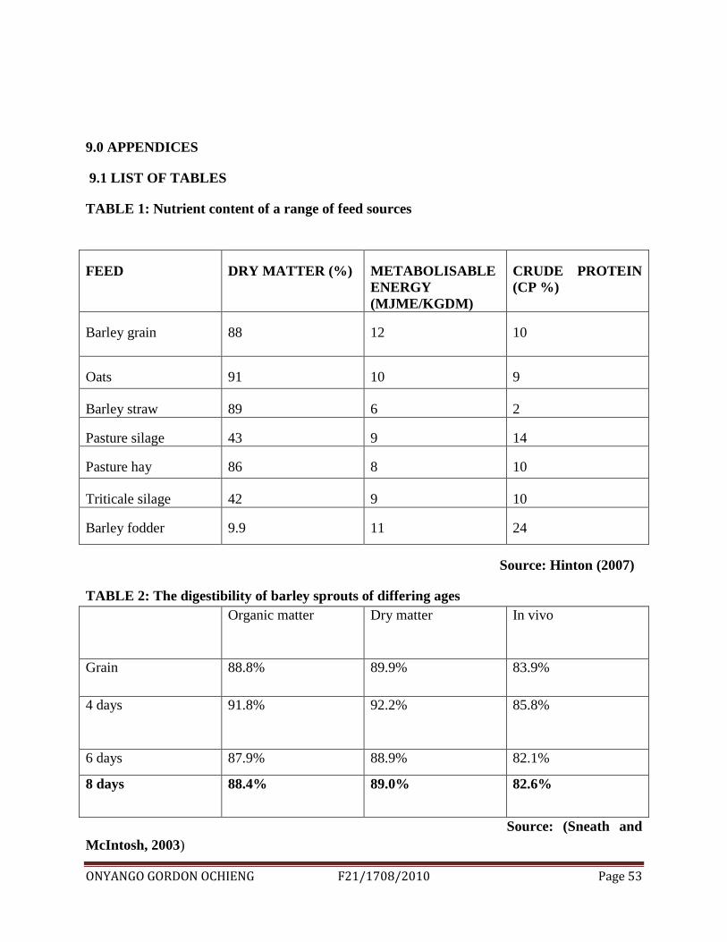
TABLE 1: Nutrient content of a range of feed sources
FEED DRY MATTER (%) METABOLISABLE
ENERGY
(MJME/KGDM)
CRUDE PROTEIN
(CP %)
Barley grain 88 12 10
Oats 91 10 9
Barley straw 89 6 2
Pasture silage 43 9 14
Pasture hay 86 8 10
Triticale silage 42 9 10
Barley fodder 9.9 11 24
Source: Hinton (2007)
TABLE 2: The digestibility of barley sprouts of differing ages
Organic matter Dry matter In vivo
Grain 88.8% 89.9% 83.9%
4 days 91.8% 92.2% 85.8%
6 days 87.9% 88.9% 82.1%
8 days 88.4% 89.0% 82.6%
Source: (Sneath and
McIntosh, 2003)
ONYANGO GORDON OCHIENG F21/1708/2010 Page 54
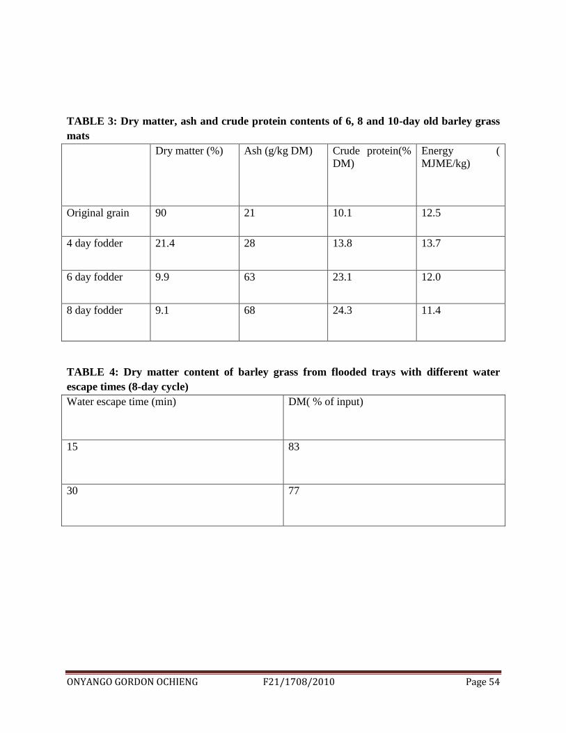
TABLE 3: Dry matter, ash and crude protein contents of 6, 8 and 10-day old barley grass
mats
Dry matter (%) Ash (g/kg DM) Crude protein(%
DM)
Energy (
MJME/kg)
Original grain 90 21 10.1 12.5
4 day fodder 21.4 28 13.8 13.7
6 day fodder 9.9 63 23.1 12.0
8 day fodder 9.1 68 24.3 11.4
TABLE 4: Dry matter content of barley grass from flooded trays with different water
escape times (8-day cycle)
Water escape time (min) DM( % of input)
15 83
30 77
ONYANGO GORDON OCHIENG F21/1708/2010 Page 55
TABLE 5
MAXIMUM RECOMMENDED WATER FLOW RATES
PIPE SIZE GPM PIPE SIZE GPM LITRES/SEC
1” 20 2” 80 5.04
1 ¼” 30 2 ½” 110 6.93
1 ½ “ 45 3” 160 10.08
ONYANGO GORDON OCHIENG F21/1708/2010 Page 56
TABLE 6
Maximum flow for PVC pipe
class GPM LITRES/SEC
¾” class 200 10-12 0.63-0756
¾ sch. 40 7-9 0.441-0.567
1” sch.40 6-20 0.378-1.26
1-1/4 class 200 12-15 0.756-0.945
1-1/4” sch. 40 22-27 1.386-1.701
TABLE 7
Spray pattern Rotors( GPM) Sprays( GPM)
Quarter circle 2 1
Half circle 4 2
Full circle 8 4
Standard pressure 50 psi 30 psi
ONYANGO GORDON OCHIENG F21/1708/2010 Page 57
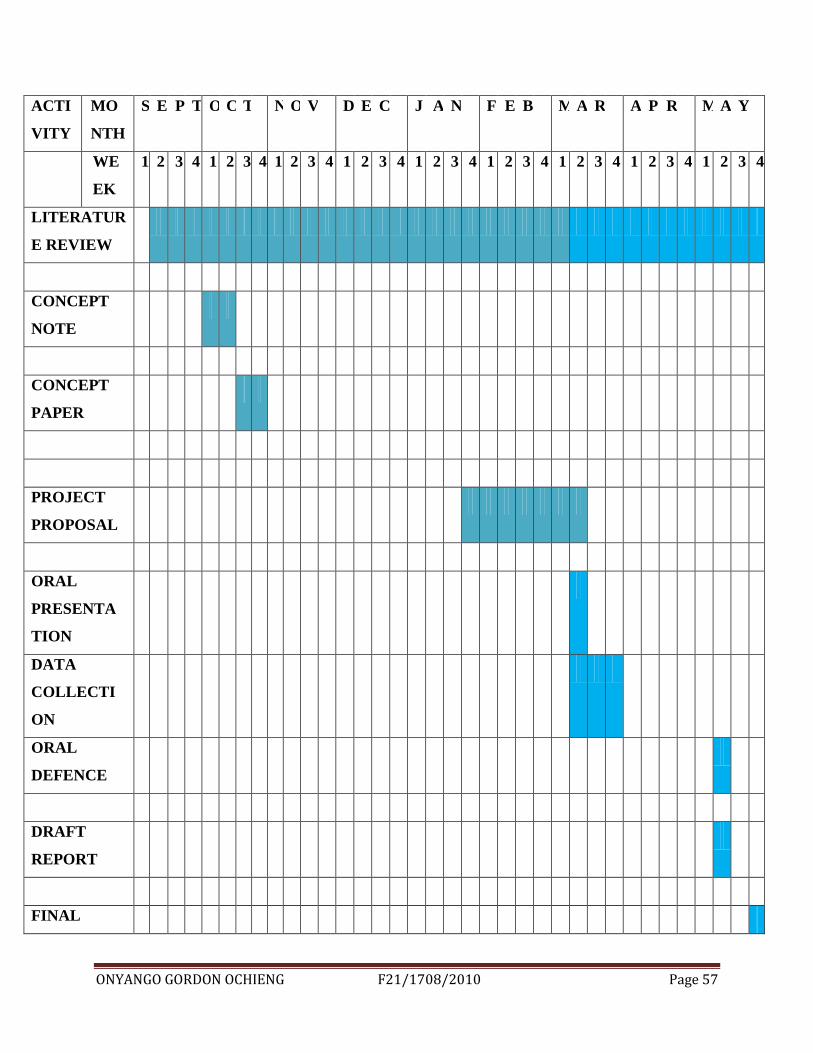
ACTI
VITY
MO
NTH
S E P T O C T N O V D E C J A N F E B M A R A P R M A Y
WE
EK
1 2 3 4 1 2 3 4 1 2 3 4 1 2 3 4 1 2 3 4 1 2 3 4 1 2 3 4 1 2 3 4 1 2 3 4
LITERATUR
E REVIEW
CONCEPT
NOTE
CONCEPT
PAPER
PROJECT
PROPOSAL
ORAL
PRESENTA
TION
DATA
COLLECTI
ON
ORAL
DEFENCE
DRAFT
REPORT
FINAL
ONYANGO GORDON OCHIENG F21/1708/2010 Page 58
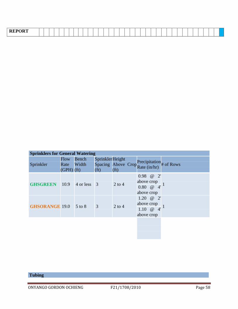
REPORT
Sprinklers for General Watering
Sprinkler
Flow
Rate
(GPH)
Bench
Width
(ft)
Sprinkler
Spacing
(ft)
Height
Above Crop
(ft)
Precipitation
Rate (in/hr) # of Rows
GHSGREEN 10.9 4 or less 3 2 to 4
0.98 @ 2'
above crop 1
0.80 @ 4'
above crop
GHSORANGE 19.0 5 to 8 3 2 to 4
1.20 @ 2'
above crop 1
1.10 @ 4'
above crop
Tubing
ONYANGO GORDON OCHIENG F21/1708/2010 Page 59
Size Max Flow
(GPM) Max Flow (GPH) Max Pressure (psi)
16mm (5/8") 4 240 60
20mm (3/4") 7 420 50
26mm (1") 13 780 45
PVC Pipe, Schedule 40
Size Max Flow (GPM) Max Flow (GPH)
1/2" 4 240
3/4" 9 540
1" 12 720
1 1/4" 22 1320
1 1/2" 30 1800
2" 50 3000
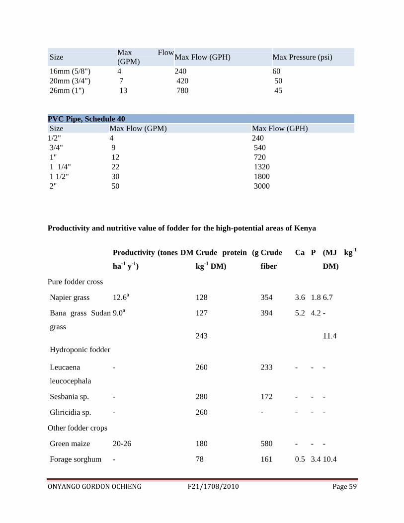
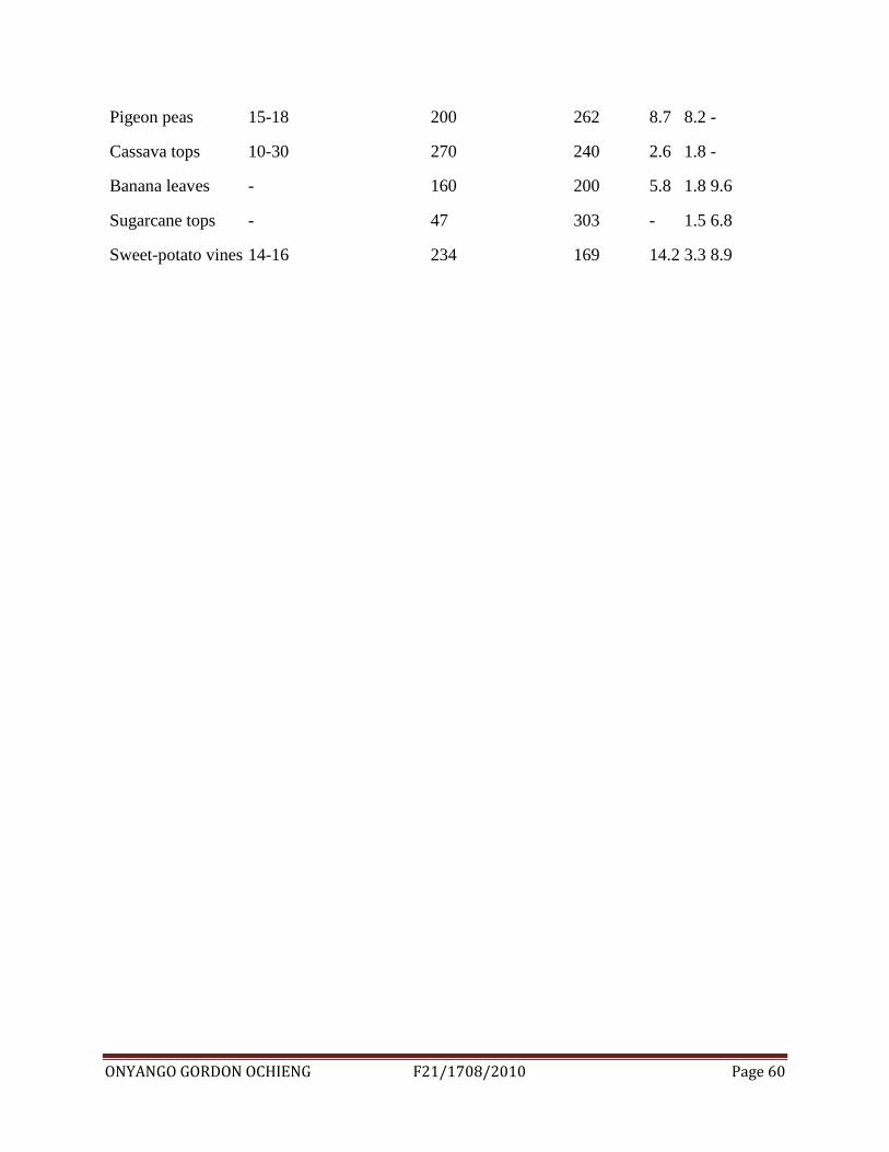
Productivity and nutritive value of fodder for the high-potential areas of Kenya
Productivity (tones DM
ha-1
y-1
)
Crude protein (g
kg-1
DM)
Crude
fiber
Ca P (MJ kg-1
DM)
Pure fodder cross
Napier grass 12.6a 128 354 3.6 1.8 6.7
Bana grass Sudan
grass
Hydroponic fodder
9.0a 127
243
394 5.2 4.2 -
11.4
Leucaena
leucocephala
- 260 233 - - -
Sesbania sp. - 280 172 - - -
Gliricidia sp. - 260 - - - -
Other fodder crops
Green maize 20-26 180 580 - - -
Forage sorghum - 78 161 0.5 3.4 10.4
ONYANGO GORDON OCHIENG F21/1708/2010 Page 60
Pigeon peas 15-18 200 262 8.7 8.2 -
Cassava tops 10-30 270 240 2.6 1.8 -
Banana leaves - 160 200 5.8 1.8 9.6
Sugarcane tops - 47 303 - 1.5 6.8
Sweet-potato vines 14-16 234 169 14.2 3.3 8.9
ONYANGO GORDON OCHIENG F21/1708/2010 Page 61
9.2 List of figures
Figure 14: Fully grown fodder: source (site photo)
ONYANGO GORDON OCHIENG F21/1708/2010 Page 62
Figure 15: stages of fodder growth: source (site photo)
ONYANGO GORDON OCHIENG F21/1708/2010 Page 63
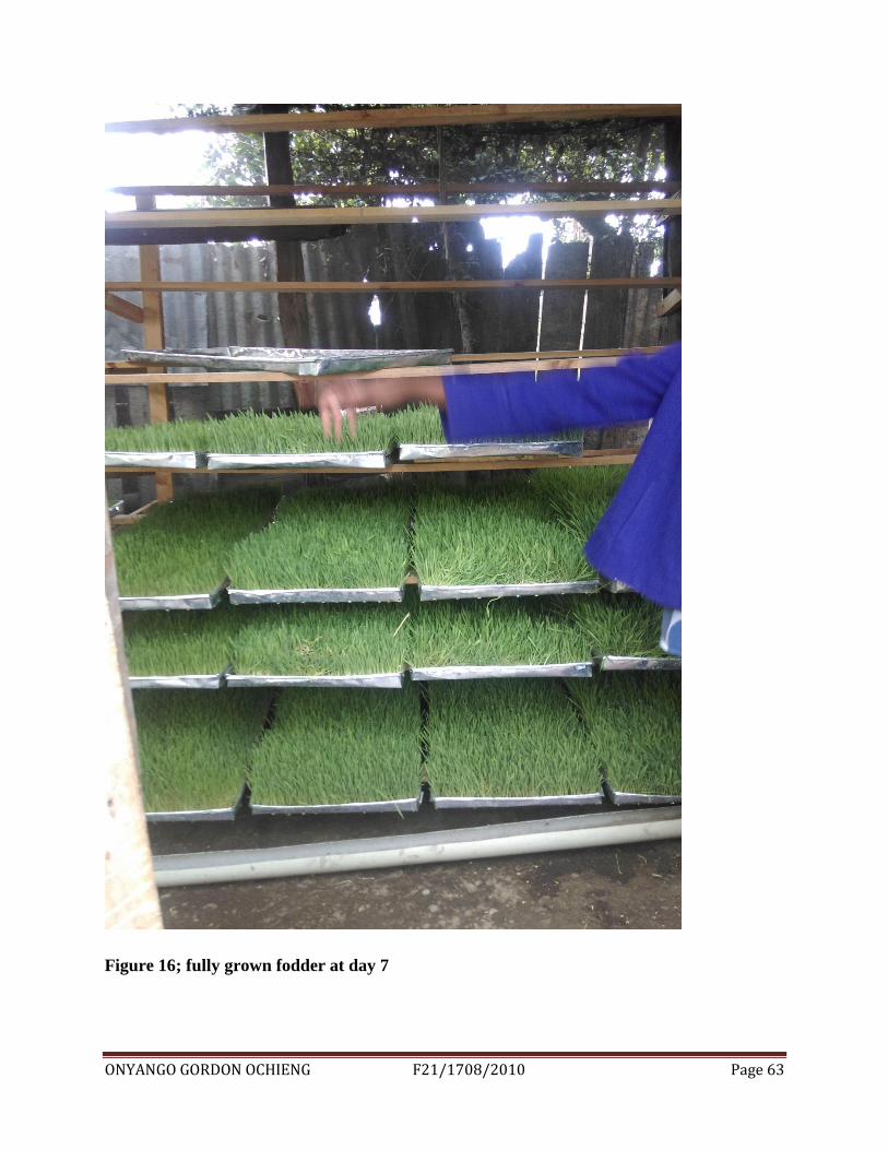
Figure 16; fully grown fodder at day 7


![8 ebe]o9bWii8 ebe]o9bWii - WordPress.com · 8 ebe]o9bWii8 ebe]o9bWii - WordPress.com ... ƒ⁄žÛ)](https://static.fdocuments.in/doc/165x107/5e491dc915c9f15b980faf4d/8-ebeo9bwii8-ebeo9bwii-8-ebeo9bwii8-ebeo9bwii-wordpresscom-a.jpg)