UNIVERSITY OF CAMBRIDGE INTERNATIONAL … paper 3.pdf · university of cambridge international...
116
This document consists of 20 printed pages. SPA SHW 00151 2/08 T76318/3 © UCLES 2009 [Turn over UNIVERSITY OF CAMBRIDGE INTERNATIONAL EXAMINATIONS International General Certificate of Secondary Education READ THESE INSTRUCTIONS FIRST Write your Centre number, candidate number and name on all the work you hand in. Write in dark blue or black pen. You may use a soft pencil for any diagrams, graphs or rough working. Do not use staples, paper clips, highlighters, glue or correction fluid. DO NOT WRITE IN ANY BARCODES. Answer all questions. You may lose marks if you do not show your working or if you do not use appropriate units. Take the weight of 1 kg to be 10 N (i.e. acceleration of free fall = 10 m/s 2 ). At the end of the examination, fasten all your work securely together. The number of marks is given in brackets [ ] at the end of each question or part question. *7761601243* PHYSICS 0625/31 Paper 3 Extended May/June 2009 1 hour 15 minutes Candidates answer on the Question Paper. No Additional Materials are required.
Transcript of UNIVERSITY OF CAMBRIDGE INTERNATIONAL … paper 3.pdf · university of cambridge international...

This document consists of 20 printed pages.
SPA SHW 00151 2/08 T76318/3© UCLES 2009 [Turn over
UNIVERSITY OF CAMBRIDGE INTERNATIONAL EXAMINATIONSInternational General Certificate of Secondary Education
READ THESE INSTRUCTIONS FIRST
Write your Centre number, candidate number and name on all the work you hand in.Write in dark blue or black pen.You may use a soft pencil for any diagrams, graphs or rough working.Do not use staples, paper clips, highlighters, glue or correction fluid.DO NOT WRITE IN ANY BARCODES.
Answer all questions.You may lose marks if you do not show your working or if you do not use appropriate units.Take the weight of 1 kg to be 10 N (i.e. acceleration of free fall = 10 m/s2).
At the end of the examination, fasten all your work securely together.The number of marks is given in brackets [ ] at the end of each question or part question.
*7761601243*
PHYSICS 0625/31
Paper 3 Extended May/June 2009
1 hour 15 minutes
Candidates answer on the Question Paper.
No Additional Materials are required.

2
0625/31/M/J/09© UCLES 2009
ForExaminer’s
Use
1 An engineering machine has a piston which is going up and down approximately 75 times per minute.
Describe carefully how a stopwatch may be used to find accurately the time for one up-and-down cycle of the piston.
.................................................................................................................................................
.................................................................................................................................................
.................................................................................................................................................
.................................................................................................................................................
.................................................................................................................................................
.................................................................................................................................................
.................................................................................................................................................
.................................................................................................................................................
........................................................................................................................................... [4]
[Total: 4]

3
0625/31/M/J/09© UCLES 2009 [Turn over
ForExaminer’s
Use
2 (a) A certain volume of water at room temperature and the same volume of ice in a freezer are each heated through the same temperature rise.
Which of them will have the greater expansion, and why?
Which? .............................................................................................................................
Why? .......................................................................................................................... [1]
(b) For strength, concrete pillars are usually reinforced with metal rods, which are embedded in the concrete before it sets.
The list below shows how much a length of 1 m of each material expands when the temperature rises by 1 °C.
aluminium 0.03 mm
concrete 0.01 mm
steel 0.01 mm
Use this information to decide which metal should be used to reinforce concrete, why it is suitable, and why the other metal is not suitable.
Which metal should be used? ..........................................................................................
Why is it suitable? ............................................................................................................
Why is the other metal unsuitable? ..................................................................................
.................................................................................................................................... [3]
[Total: 4]

4
0625/31/M/J/09© UCLES 2009
ForExaminer’s
Use
3 (a) Fig. 3.1 shows a skier descending a hillside. Fig. 3.2 shows the speed/time graph of his motion.
speedm / s
6
4
2
200
4 6 8time / s
Fig. 3.1 Fig. 3.2
(i) How can you tell that the acceleration of the skier is constant during the 8 s shown on the graph?
............................................................................................................................ [1]
(ii) Calculate the acceleration of the skier.
acceleration = ................................................ [2]
(b) Another skier starts from rest at the top of the slope. As his speed increases the friction force on the skier increases.
(i) State the effect of this increasing friction force on the acceleration.
............................................................................................................................ [1]
(ii) Eventually the speed of the skier becomes constant.
What can be said about the friction force when the speed is constant?
............................................................................................................................ [2]

5
0625/31/M/J/09© UCLES 2009 [Turn over
ForExaminer’s
Use
(iii) 1. On the axes of Fig. 3.3, sketch a possible speed/time graph for the motion of the second skier.
00 time
speed
Fig. 3.3
2. On your graph, mark with the letter A a region where the acceleration is not constant. Mark with the letter B the region where the speed is constant. [4]
[Total: 10]

6
0625/31/M/J/09© UCLES 2009
ForExaminer’s
Use
4 (a) In an accident, a truck goes off the road and into a ditch. Two breakdown vehicles A and B are used to pull the truck out of the ditch, as shown in Fig. 4.1.
ditch
road
breakdownvehicles
A
B
45°
Fig. 4.1

7
0625/31/M/J/09© UCLES 2009 [Turn over
ForExaminer’s
Use
At one point in the rescue operation, breakdown vehicle A is exerting a force of 4000 N and breakdown vehicle B is exerting a force of 2000 N.
(i) Using a scale of 1 cm = 500 N, make a scale drawing to show the resultant force on the truck.
[4]
(ii) Use your diagram to find the magnitude and direction of the resultant force on the truck.
magnitude of resultant force = ......................................................
direction of resultant force = ............................... to direction of road [2]
(b) (i) State why the resultant force is an example of a vector quantity.
............................................................................................................................ [1]
(ii) Give an example of a vector quantity that is not a force.
............................................................................................................................ [1]
[Total: 8]

8
0625/31/M/J/09© UCLES 2009
ForExaminer’s
Use
5 A wind turbine has blades, which sweep out an area of diameter 25 m.
25 m
blades
Fig. 5.1
(a) The wind is blowing directly towards the wind turbine at a speed of 12 m / s. At this wind speed, 7500 kg of air passes every second through the circular area swept out by the blades.
(i) Calculate the kinetic energy of the air travelling at 12 m / s, which passes through the circular area in 1 second.
kinetic energy = ................................................ [3]
(ii) The turbine converts 10% of the kinetic energy of the wind to electrical energy.
Calculate the electrical power output of the turbine. State any equation that you use.
power = ................................................ [3]

9
0625/31/M/J/09© UCLES 2009 [Turn over
ForExaminer’s
Use
(b) On another day, the wind speed is half that in (a).
(i) Calculate the mass of air passing through the circular area per second on this day.
mass = ................................................ [1]
(ii) Calculate the power output of the wind turbine on the second day as a fraction of that on the first day.
fraction = ................................................ [3]
[Total: 10]

10
0625/31/M/J/09© UCLES 2009
ForExaminer’s
Use
6 (a) A man squeezes a pin between his thumb and finger, as shown in Fig. 6.1.
finger
pinhead
pin
thumb
Fig. 6.1
The finger exerts a force of 84 N on the pinhead.
The pinhead has an area of 6.0 × 10⁻⁵ m2.
(i) Calculate the pressure exerted by the finger on the pinhead.
pressure = ................................................ [2]
(ii) State the value of the force exerted by the pin on the thumb.
................................................. [1]
(iii) Explain why the pin causes more pain in the man’s thumb than in his finger.
..................................................................................................................................
............................................................................................................................ [2]

11
0625/31/M/J/09© UCLES 2009 [Turn over
ForExaminer’s
Use
(b) The density of the water in a swimming pool is 1000 kg / m3. The pool is 3 m deep.
(i) Calculate the pressure of the water at the bottom of the pool.
pressure = ................................................ [2]
(ii) Another pool has the same depth of water, but has twice the area.
State the pressure of the water at the bottom of this pool.
pressure = ................................................ [1]
[Total: 8]

12
0625/31/M/J/09© UCLES 2009
ForExaminer’s
Use
7 (a) Some water is poured onto a plastic table-top, forming a puddle. The same volume of water is poured into a plastic dish, which is placed alongside the puddle. This is illustrated in Fig. 7.1.
water inpuddle
water indish
Fig. 7.1
Both lots of water begin to evaporate.
(i) In terms of the behaviour of molecules, describe what happens during the process of evaporation.
..................................................................................................................................
..................................................................................................................................
..................................................................................................................................
............................................................................................................................ [2]
(ii) Explain why the puddle dries out more rapidly than the water in the dish.
..................................................................................................................................
..................................................................................................................................
..................................................................................................................................
............................................................................................................................ [2]
(iii) State two changes that would make both lots of water evaporate more rapidly.
1. ...............................................................................................................................
2. ......................................................................................................................... [2]
13
0625/31/M/J/09© UCLES 2009 [Turn over
ForExaminer’s
Use
(b) In a place where refrigeration is not possible, a person attempts to keep a bottle of milk cool by using the procedure illustrated in Fig. 7.2.
bottle
damp cloth
milk
bowlwater
Fig. 7.2
Explain in terms of molecules why this procedure would be successful.
..........................................................................................................................................
..........................................................................................................................................
.................................................................................................................................... [3]
[Total: 9]

14
0625/31/M/J/09© UCLES 2009
ForExaminer’s
Use
8 In an optics lesson, a Physics student traces the paths of three rays of light near the boundary between medium A and air. The student uses a protractor to measure the various angles.
Fig. 8.1 illustrates the three measurements.
180 0
1020
3040
5060
70 80 100110
120
130
140
150160
170180
170
160
150
140
130
120110
100 90 8070
60
50
40
3020
100 air
mediumA
ray1
180 0
1020
3040
5060
70 80 100110
120
130
140
150160
170180
170
160
150
140
130
120110
100 90 8070
60
50
40
3020
100 air
mediumA
ray2
180 0
1020
3040
5060
70 80 100110
120
130
140
150160
170180
170
160
150
140
130
120110
100 90 8070
60
50
40
3020
100 air
mediumA
ray3
Fig. 8.1

15
0625/31/M/J/09© UCLES 2009 [Turn over
ForExaminer’s
Use
(a) State which is the optically denser medium, A or air, and how you can tell this.
..........................................................................................................................................
.................................................................................................................................... [1]
(b) State in which medium the light travels the faster, and how you know this.
..........................................................................................................................................
.................................................................................................................................... [1]
(c) State the critical angle of medium A.
................................................... [1]
(d) State the full name for what is happening to ray 3.
................................................... [1]
(e) The refractive index of medium A is 1.49.
Calculate the value of the angle of refraction of ray 1, showing all your working.
angle of refraction = ................................................ [2]
(f) The speed of light in air is 3.0 × 10⁸ m / s.
Calculate the speed of light in medium A, showing all your working.
speed of light = ................................................ [2]
[Total: 8]

16
0625/31/M/J/09© UCLES 2009
ForExaminer’s
Use
9 (a) Fig. 9.1 shows an a.c. supply connected in series to a diode and a resistor.
Fig. 9.1
On the axes of Fig. 9.2, draw a graph showing the variation of the current in the resistor. [1]
current
time0
Fig. 9.2

17
0625/31/M/J/09© UCLES 2009 [Turn over
ForExaminer’s
Use
(b) Fig. 9.3 shows four attempts, A, B, C and D, to connect a circuit known as a bridge rectifier.
The circuit is connected to a 12 V a.c. supply.
red black
A
red black
B
red black
C
red black
D
12 V 12 V
12 V 12 V
Fig. 9.3
(i) In which circuit will the direction of the conventional current in the resistor always be from red to black?
................................................. [1]
(ii) On the circuit you chose in (b)(i), clearly indicate with arrows the path of the conventional current in the circuit when the upper terminal of the a.c. supply is positive with respect to the lower terminal. [2]
[Total: 4]

18
0625/31/M/J/09© UCLES 2009
ForExaminer’s
Use
10 The circuit shown in Fig. 10.1 uses a 12 V battery.
12 V
16 8 S
A
Fig. 10.1
(a) Switch S is open, as shown in Fig. 10.1.
State the value of
(i) the reading on the ammeter,
reading = ................................................ [1]
(ii) the potential difference (p.d.) across S.
p.d. = ................................................ [1]
(b) Switch S is now closed.
(i) Calculate the current in the ammeter.
current = ................................................ [2]
(ii) Calculate the p.d. across the 8 resistor.
p.d. = ................................................ [2]

19
0625/31/M/J/09© UCLES 2009 [Turn over
ForExaminer’s
Use
(c) The two resistors are now connected in parallel.
Calculate the new reading on the ammeter when S is closed, stating clearly any equations that you use.
reading = ................................................ [4]
[Total: 10]
Question 11 is on the next page.

20
0625/31/M/J/09© UCLES 2009
ForExaminer’s
Use
Permission to reproduce items where third-party owned material protected by copyright is included has been sought and cleared where possible. Every reasonable effort has been made by the publisher (UCLES) to trace copyright holders, but if any items requiring clearance have unwittingly been included, the publisher will be pleased to make amends at the earliest possible opportunity.
University of Cambridge International Examinations is part of the Cambridge Assessment Group. Cambridge Assessment is the brand name of University of Cambridge Local Examinations Syndicate (UCLES), which is itself a department of the University of Cambridge.
11 A beam of ionising radiation, containing -particles, -particles and -rays, is travelling left to right across the page. A magnetic field acts perpendicularly into the page.
(a) In the table below, tick the boxes that describe the deflection of each of the types of radiation as it passes through the magnetic field. One line has been completed, to help you.
not deflected
deflectedtowards
top of page
deflectedtowards
bottom of page
largedeflection
smalldeflection
-particles
-particles
-rays
[3]
(b) An electric field is now applied, in the same region as the magnetic field and at the same time as the magnetic field.
What is the direction of the electric field in order to cancel out the deflection of the -particles?
.................................................................................................................................... [2]
[Total: 5]

This document consists of 20 printed pages.
SPA SHW 00151 2/08 T76321/3© UCLES 2009 [Turn over
UNIVERSITY OF CAMBRIDGE INTERNATIONAL EXAMINATIONSInternational General Certificate of Secondary Education
READ THESE INSTRUCTIONS FIRST
Write your Centre number, candidate number and name on all the work you hand in.Write in dark blue or black pen.You may use a soft pencil for any diagrams, graphs or rough working.Do not use staples, paper clips, highlighters, glue or correction fluid.DO NOT WRITE IN ANY BARCODES.
Answer all questions.You may lose marks if you do not show your working or if you do not use appropriate units.Take the weight of 1 kg to be 10 N (i.e. acceleration of free fall = 10 m/s2).
At the end of the examination, fasten all your work securely together.The number of marks is given in brackets [ ] at the end of each question or part question.
*2309904546*
PHYSICS 0625/32
Paper 3 Extended May/June 2009
1 hour 15 minutes
Candidates answer on the Question Paper.
No Additional Materials are required.

2
0625/32/M/J/09© UCLES 2009
ForExaminer’s
Use
1 A laboratory technician has ten pieces of plastic, all cut from the same thin sheet.
The technician wishes to find the thickness of a piece of plastic as accurately as possible.
(a) Name the instrument that should be used.
................................................. [1]
(b) Describe how the instrument should be used to find the thickness.
..........................................................................................................................................
..........................................................................................................................................
..........................................................................................................................................
..........................................................................................................................................
..........................................................................................................................................
..........................................................................................................................................
..........................................................................................................................................
..........................................................................................................................................
..........................................................................................................................................
.................................................................................................................................... [3]
[Total: 4]

3
0625/32/M/J/09© UCLES 2009 [Turn over
ForExaminer’s
Use
2 (a) A certain volume of water at room temperature and the same volume of ice in a freezer are each heated through the same temperature rise.
Which of them will have the greater expansion, and why?
Which? .............................................................................................................................
Why? .......................................................................................................................... [1]
(b) For strength, concrete pillars are usually reinforced with metal rods, which are embedded in the concrete before it sets.
The list below shows how much a length of 1 m of each material expands when the temperature rises by 1 °C.
aluminium 0.03 mm
concrete 0.01 mm
steel 0.01 mm
Use this information to decide which metal should be used to reinforce concrete, why it is suitable, and why the other metal is not suitable.
Which metal should be used? ..........................................................................................
Why is it suitable? ............................................................................................................
Why is the other metal unsuitable? ..................................................................................
.................................................................................................................................... [3]
[Total: 4]
4
0625/32/M/J/09© UCLES 2009
ForExaminer’s
Use
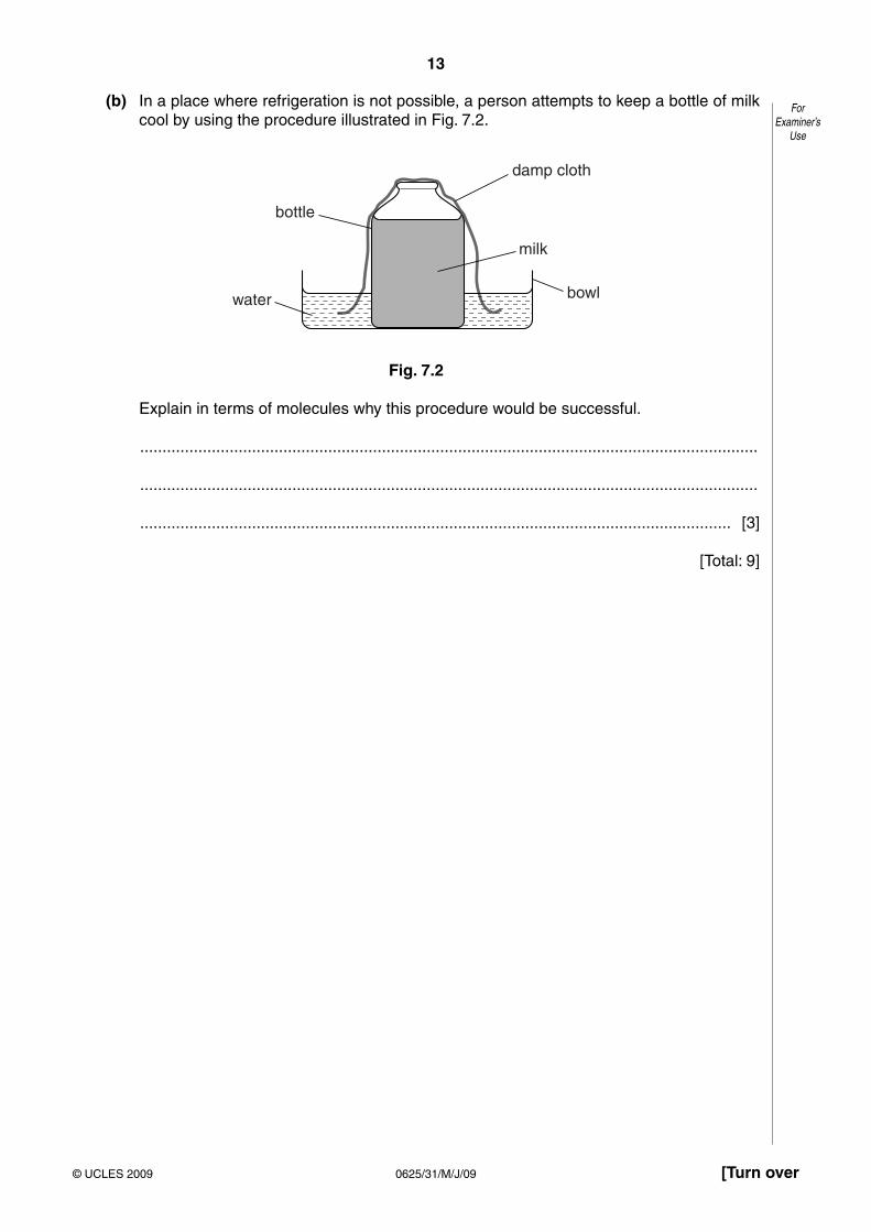
3 A free-fall parachutist jumps out of an aeroplane, but doesn’t open his parachute until after some time has elapsed.
Fig. 3.1 shows the graph of his speed during the fall.
A B
C D
00
speed
time
Fig. 3.1
(a) What is the value of the acceleration of the parachutist immediately after he has jumped from the aeroplane?
................................................. [1]
(b) How can you tell that the acceleration decreases until point A on the graph is reached?
..........................................................................................................................................
.................................................................................................................................... [1]
(c) State why the acceleration of the parachutist decreases until point A on the graph.
..........................................................................................................................................
..........................................................................................................................................
..........................................................................................................................................
.................................................................................................................................... [2]
(d) Consider section AB of the graph.
(i) State what is happening to the parachutist’s speed in this section.
............................................................................................................................ [1]
(ii) What can be said about the forces on the parachutist during this section?
..................................................................................................................................
............................................................................................................................ [1]

5
0625/32/M/J/09© UCLES 2009 [Turn over
ForExaminer’s
Use
(e) At which point did the parachutist open his parachute?
................................................. [1]
(f) Explain why the speed decreases from B to C.
..........................................................................................................................................
..........................................................................................................................................
.................................................................................................................................... [2]
[Total: 9]

6
0625/32/M/J/09© UCLES 2009
ForExaminer’s
Use
4 (a) In an accident, a truck goes off the road and into a ditch. Two breakdown vehicles A and B are used to pull the truck out of the ditch, as shown in Fig. 4.1.
ditch
road
breakdownvehicles
A
B
45°
Fig. 4.1
7
0625/32/M/J/09© UCLES 2009 [Turn over
ForExaminer’s
Use
At one point in the rescue operation, breakdown vehicle A is exerting a force of 4000 N and breakdown vehicle B is exerting a force of 2000 N.
(i) Using a scale of 1 cm = 500 N, make a scale drawing to show the resultant force on the truck.
[4]
(ii) Use your diagram to find the magnitude and direction of the resultant force on the truck.
magnitude of resultant force = ......................................................
direction of resultant force = ............................... to direction of road [2]
(b) (i) State why the resultant force is an example of a vector quantity.
............................................................................................................................ [1]
(ii) Give an example of a vector quantity that is not a force.
............................................................................................................................ [1]
[Total: 8]

8
0625/32/M/J/09© UCLES 2009
ForExaminer’s
Use
5 A wind turbine has blades, which sweep out an area of diameter 25 m.
25 m
blades
Fig. 5.1
(a) The wind is blowing directly towards the wind turbine at a speed of 12 m / s. At this wind speed, 7500 kg of air passes every second through the circular area swept out by the blades.
(i) Calculate the kinetic energy of the air travelling at 12 m / s, which passes through the circular area in 1 second.
kinetic energy = ................................................ [3]
(ii) The turbine converts 10% of the kinetic energy of the wind to electrical energy.
Calculate the electrical power output of the turbine. State any equation that you use.
power = ................................................ [3]
9
0625/32/M/J/09© UCLES 2009 [Turn over
ForExaminer’s
Use
(b) On another day, the wind speed is half that in (a).
(i) Calculate the mass of air passing through the circular area per second on this day.
mass = ................................................ [1]
(ii) Calculate the power output of the wind turbine on the second day as a fraction of that on the first day.
fraction = ................................................ [3]
[Total: 10]

10
0625/32/M/J/09© UCLES 2009
ForExaminer’s
Use
6 (a) A man squeezes a pin between his thumb and finger, as shown in Fig. 6.1.
finger
pinhead
pin
thumb
Fig. 6.1
The finger exerts a force of 84 N on the pinhead.
The pinhead has an area of 6.0 × 10⁻⁵ m2.
(i) Calculate the pressure exerted by the finger on the pinhead.
pressure = ................................................ [2]
(ii) State the value of the force exerted by the pin on the thumb.
................................................. [1]
(iii) Explain why the pin causes more pain in the man’s thumb than in his finger.
..................................................................................................................................
............................................................................................................................ [2]

11
0625/32/M/J/09© UCLES 2009 [Turn over
ForExaminer’s
Use
(b) The density of the water in a swimming pool is 1000 kg / m3. The pool is 3 m deep.
(i) Calculate the pressure of the water at the bottom of the pool.
pressure = ................................................ [2]
(ii) Another pool has the same depth of water but has twice the area.
State the pressure of the water at the bottom of this pool.
pressure = ................................................ [1]
[Total: 8]

12
0625/32/M/J/09© UCLES 2009
ForExaminer’s
Use
7 (a) Some water is poured onto a plastic table-top, forming a puddle. The same volume of water is poured into a plastic dish, which is placed alongside the puddle. This is illustrated in Fig. 7.1.
water inpuddle
water indish
Fig. 7.1
Both lots of water begin to evaporate.
(i) In terms of the behaviour of molecules, describe what happens during the process of evaporation.
..................................................................................................................................
..................................................................................................................................
..................................................................................................................................
............................................................................................................................ [2]
(ii) Explain why the puddle dries out more rapidly than the water in the dish.
..................................................................................................................................
..................................................................................................................................
..................................................................................................................................
............................................................................................................................ [2]
(iii) State two changes that would make both lots of water evaporate more rapidly.
1. ...............................................................................................................................
2. ......................................................................................................................... [2]

13
0625/32/M/J/09© UCLES 2009 [Turn over
ForExaminer’s
Use
(b) In a place where refrigeration is not possible, a person attempts to keep a bottle of milk cool by using the procedure illustrated in Fig. 7.2.
bottle
damp cloth
milk
bowlwater
Fig. 7.2
Explain in terms of molecules why this procedure would be successful.
..........................................................................................................................................
..........................................................................................................................................
.................................................................................................................................... [3]
[Total: 9]

14
0625/32/M/J/09© UCLES 2009
ForExaminer’s
Use
8 In an optics lesson, a Physics student traces the paths of three rays of light near the boundary between medium A and air. The student uses a protractor to measure the various angles.
Fig. 8.1 illustrates the three measurements.
180 0
1020
3040
5060
70 80 100110
120
130
140
150160
170180
170
160
150
140
130
120110
100 90 8070
60
50
40
3020
100 air
mediumA
ray1
180 0
1020
3040
5060
70 80 100110
120
130
140
150160
170180
170
160
150
140
130
120110
100 90 8070
60
50
40
3020
100 air
mediumA
ray2
180 0
1020
3040
5060
70 80 100110
120
130
140
150160
170180
170
160
150
140
130
120110
100 90 8070
60
50
40
3020
100 air
mediumA
ray3
Fig. 8.1

15
0625/32/M/J/09© UCLES 2009 [Turn over
ForExaminer’s
Use
(a) State which is the optically denser medium, A or air, and how you can tell this.
..........................................................................................................................................
.................................................................................................................................... [1]
(b) State in which medium the light travels the faster, and how you know this.
..........................................................................................................................................
.................................................................................................................................... [1]
(c) State the critical angle of medium A.
................................................... [1]
(d) State the full name for what is happening to ray 3.
................................................... [1]
(e) The refractive index of medium A is 1.49.
Calculate the value of the angle of refraction of ray 1, showing all your working.
angle of refraction = ................................................ [2]
(f) The speed of light in air is 3.0 × 10⁸ m / s.
Calculate the speed of light in medium A, showing all your working.
speed of light = ................................................ [2]
[Total: 8]

16
0625/32/M/J/09© UCLES 2009
ForExaminer’s
Use
9 (a) Fig. 9.1 shows an a.c. supply connected in series to a diode and a resistor.
Fig. 9.1
On the axes of Fig. 9.2, draw a graph showing the variation of the current in the resistor. [1]
current
time0
Fig. 9.2

17
0625/32/M/J/09© UCLES 2009 [Turn over
ForExaminer’s
Use
(b) Fig. 9.3 shows four attempts, A, B, C and D, to connect a circuit known as a bridge rectifier.
The circuit is connected to a 12 V a.c. supply.
red black
A
red black
B
red black
C
red black
D
12 V 12 V
12 V 12 V
Fig. 9.3
(i) In which circuit will the direction of the conventional current in the resistor always be from red to black?
................................................. [1]
(ii) On the circuit you chose in (b)(i), clearly indicate with arrows the path of the conventional current through the circuit when the upper terminal of the a.c. supply is positive with respect to the lower terminal. [2]
[Total: 4]

18
0625/32/M/J/09© UCLES 2009
ForExaminer’s
Use
10 The circuit shown in Fig. 10.1 uses a 12 V battery. A and B are identical lamps, each designed to work from a 6 V supply.
12 V
A
18 Ω18 Ω
S
B
V
Fig. 10.1
(a) Switch S is open, as shown in Fig. 10.1.
(i) State the value of
1. the potential difference (p.d.) across S,
p.d. = ................................................ [1]
2. the reading on the voltmeter.
reading = ................................................ [1]
(ii) Comment on the brightness of the two lamps.
............................................................................................................................ [1]
(b) Switch S is now closed.
(i) State the new reading on the voltmeter.
new reading = ................................................ [1]
(ii) Comment on the brightness of the two lamps.
............................................................................................................................ [1]
(iii) Under these conditions, each lamp has a resistance of 18 .
Calculate the current in each lamp.
current = ................................................ [3]

19
0625/32/M/J/09© UCLES 2009 [Turn over
ForExaminer’s
Use
(c) With switch S open, lamp B is connected in parallel with lamp A. With no current, each lamp has a resistance of 1.8 .
(i) Calculate the value of the combined resistance of A and B.
combined resistance = ................................................ [2]
(ii) State why it would not be wise to close S when A and B are connected in parallel.
..................................................................................................................................
............................................................................................................................ [1]
[Total: 11]
Question 11 is on the next page.

20
0625/32/M/J/09© UCLES 2009
ForExaminer’s
Use
11 A beam of ionising radiation, containing -particles, -particles and -rays, is travelling left to right across the page. A magnetic field acts perpendicularly into the page.
(a) In the table below, tick the boxes which describe the deflection of each of the types of radiation as it passes through the magnetic field. One line has been completed, to help you.
not deflected
deflectedtowards
top of page
deflectedtowards
bottom of page
largedeflection
smalldeflection
-particles
-particles
-rays
[3]
(b) An electric field is now applied, in the same region as the magnetic field, and at the same time as the magnetic field.
What is the direction of the electric field, in order to cancel out the deflection of the -particles?
.................................................................................................................................... [2]
[Total: 5]
Permission to reproduce items where third-party owned material protected by copyright is included has been sought and cleared where possible. Every reasonable effort has been made by the publisher (UCLES) to trace copyright holders, but if any items requiring clearance have unwittingly been included, the publisher will be pleased to make amends at the earliest possible opportunity.
University of Cambridge International Examinations is part of the Cambridge Assessment Group. Cambridge Assessment is the brand name of University of Cambridge Local Examinations Syndicate (UCLES), which is itself a department of the University of Cambridge.

This document consists of 16 printed pages.
SPA (SHW 00013 3/07) T49725/4© UCLES 2008 [Turn over
UNIVERSITY OF CAMBRIDGE INTERNATIONAL EXAMINATIONSInternational General Certificate of Secondary Education
READ THESE INSTRUCTIONS FIRST
Write your Centre number, candidate number and name on all the work you hand in.Write in dark blue or black pen.You may use a soft pencil for any diagrams, graphs or rough working.Do not use staples, paper clips, highlighters, glue or correction fluid.DO NOT WRITE IN ANY BARCODES.
Answer all questions.You may lose marks if you do not show your working or if you do not use appropriate units.Take the weight of 1 kg to be 10 N (i.e. acceleration of free fall = 10 m/s2).
At the end of the examination, fasten all your work securely together.The number of marks is given in brackets [ ] at the end of each question or part question.
*2847911916*
PHYSICS 0625/32
Paper 3 Extended May/June 2008
1 hour 15 minutes
Candidates answer on the Question Paper.
No Additional Materials are required.

2
0625/32/M/J/08© UCLES 2008
ForExaminer’s
Use
1 Fig. 1.1 shows the axes for a speed-time graph.
0 1 2 3 4 50
10
20
30
time / s
m / sspeed
Fig. 1.1
(a) An object A falls freely from rest with the acceleration due to gravity (g = 10 m/s2). It is not affected by air resistance.
On Fig. 1.1, draw the graph of the motion of object A. [1]
(b) Using your graph, or an alternative method, calculate the distance fallen in the first 2 s by object A in part (a).
distance fallen = . ................................................. [2]
(c) A second object B falls through the air from rest, but is affected by air resistance. It reaches a terminal velocity of 14 m/s.
On Fig. 1.1, draw a possible graph for object B, including the region where it is travelling at terminal velocity. [1]
3
0625/32/M/J/08© UCLES 2008 [Turn over
ForExaminer’s
Use
(d) (i) Suggest a possible difference between objects A and B that could lead to B reaching a terminal velocity.
..................................................................................................................................
..................................................................................................................................
............................................................................................................................ [1]
(ii) Explain, in terms of the forces on B, why B reaches a terminal velocity.
..................................................................................................................................
..................................................................................................................................
..................................................................................................................................
..................................................................................................................................
............................................................................................................................ [2]
(e) Object A experiences a gravitational force of 2.0 N.
(i) State the value of the weight of A.
weight = . ................................................. [1]
(ii) Calculate the mass of A.
mass = . ................................................. [1]
(f) Object A is floating in equilibrium on a liquid.
State the value of the upward force of the liquid on A.
upward force = ................................................ [1]
[Total: 10]

4
0625/32/M/J/08© UCLES 2008
ForExaminer’s
Use
2 (a) Name the process by which energy is released in the core of the Sun.
.................................................................................................................................... [1]
(b) Describe how energy from the Sun becomes stored energy in water behind a dam.
..........................................................................................................................................
..........................................................................................................................................
..........................................................................................................................................
..........................................................................................................................................
..........................................................................................................................................
.................................................................................................................................... [3]
(c) Data for two small power stations is given in Table 2.1.
input to power station output of power station
gas-fired 100 MW 25 MW
hydroelectric 90 MW 30 MW
Table 2.1
(i) State what is meant by the efficiency of a power station.
..................................................................................................................................
..................................................................................................................................
..................................................................................................................................
............................................................................................................................ [1]
(ii) Use the data in Table 2.1 to explain that the hydroelectric station is more efficient than the gas-fired power station.
..................................................................................................................................
..................................................................................................................................
..................................................................................................................................
..................................................................................................................................
............................................................................................................................ [1]
[Total: 6]

5
0625/32/M/J/08© UCLES 2008 [Turn over
ForExaminer’s
Use
3 A cyclist rides up and then back down the hill shown in Fig. 3.1.
14 m
top of hill
starting andfinishing point
Fig. 3.1
The cyclist and her bicycle have a combined mass of 90 kg. She pedals up to the top and then stops. She turns around and rides back to the bottom without pedalling or using her brakes.
(a) Calculate the potential energy gained by the cyclist and her bicycle when she has reached the top of the hill.
potential energy = ................................................ [2]
(b) Calculate the maximum speed she could have when she arrives back at the starting point.
speed = ................................................ [3]
(c) Explain why her actual speed will be less than that calculated in (b).
..........................................................................................................................................
..........................................................................................................................................
..........................................................................................................................................
.................................................................................................................................... [1]
[Total: 6]
6
0625/32/M/J/08© UCLES 2008
ForExaminer’s
Use
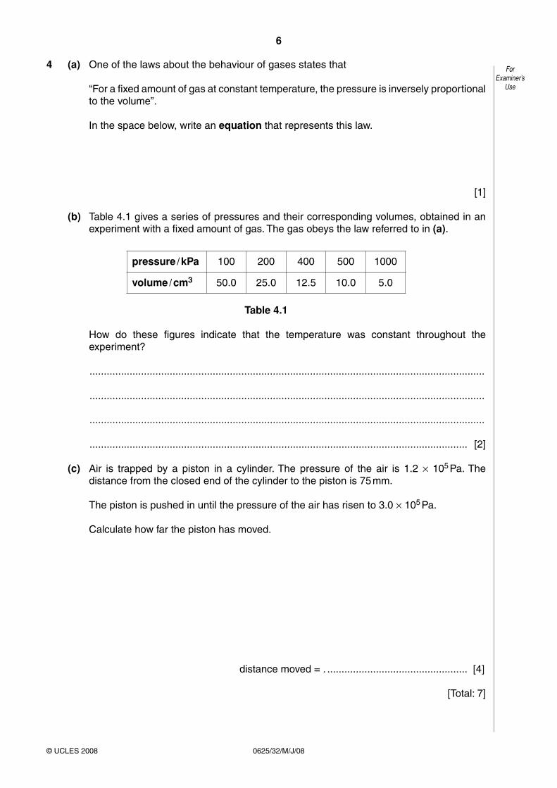
4 (a) One of the laws about the behaviour of gases states that
“For a fixed amount of gas at constant temperature, the pressure is inversely proportional to the volume”.
In the space below, write an equation that represents this law.
[1]
(b) Table 4.1 gives a series of pressures and their corresponding volumes, obtained in an experiment with a fixed amount of gas. The gas obeys the law referred to in (a).
pressure / kPa 100 200 400 500 1000
volume / cm3 50.0 25.0 12.5 10.0 5.0
Table 4.1
How do these figures indicate that the temperature was constant throughout the experiment?
..........................................................................................................................................
..........................................................................................................................................
..........................................................................................................................................
.................................................................................................................................... [2]
(c) Air is trapped by a piston in a cylinder. The pressure of the air is 1.2 × 10⁵ Pa. The distance from the closed end of the cylinder to the piston is 75 mm.
The piston is pushed in until the pressure of the air has risen to 3.0 × 10⁵ Pa.
Calculate how far the piston has moved.
distance moved = . ................................................. [4]
[Total: 7]

7
0625/32/M/J/08© UCLES 2008 [Turn over
ForExaminer’s
Use
5 (a) Explain, in terms of molecules, how thermal expansion takes place in a solid and in a gas.
solid .................................................................................................................................
..........................................................................................................................................
..........................................................................................................................................
..........................................................................................................................................
..........................................................................................................................................
gas ...................................................................................................................................
..........................................................................................................................................
..........................................................................................................................................
..........................................................................................................................................
.................................................................................................................................... [4]
(b) Complete Table 5.1 to show the relative expansion of equal volumes of liquids, gases and solids.
Choose words from
much less, slightly less, slightly more and much more. [2]
state of matter expansion compared to solids, for the same temperature rise
liquids
gases
Table 5.1
(c) Alcohol is often used in thermometers.
State one property of alcohol that makes it suitable for use in thermometers.
..........................................................................................................................................
..........................................................................................................................................
.................................................................................................................................... [1]
[Total: 7]

8
0625/32/M/J/08© UCLES 2008
ForExaminer’s
Use
6 Fig. 6.1 shows an object, the tip of which is labelled O, placed near a lens L.
The two principal foci of the lens are F1 and F2.
F1F2
L O
Fig. 6.1
(a) On Fig. 6.1, draw the paths of two rays from the tip of the object so that they pass through the lens and continue beyond.
Complete the diagram to locate the image of the tip of the object. Draw in the whole image and label it I. [2]
(b) State two changes to the image when the object is moved
(i) a small distance closer to the lens,
1. ...............................................................................................................................
2. ......................................................................................................................... [2]
(ii) to a position between F1 and the lens.
1. ...............................................................................................................................
2. ......................................................................................................................... [2]
[Total: 6]

9
0625/32/M/J/08© UCLES 2008 [Turn over
ForExaminer’s
Use
7 Fig. 7.1 and Fig. 7.2 show wavefronts of light approaching a plane mirror and a rectangular glass block, respectively.
direction of travelof wavefronts
mirror
Fig. 7.1
direction of travelof wavefronts
glass block
Fig. 7.2
(a) On Fig. 7.1 and on Fig. 7.2 draw wavefronts to show what happens after the waves strike the surface. [4]
(b) In Fig. 7.2, the waves approaching the block have a speed of 3.0 × 10⁸ m/s and an angle of incidence of 70°. The refractive index of the glass of the block is 1.5.
(i) Calculate the speed of light waves in the block.
speed = ................................................ [2]
(ii) Calculate the angle of refraction in the block.
angle = ................................................ [2]
[Total: 8]

10
0625/32/M/J/08© UCLES 2008
ForExaminer’s
Use
8 Fig. 8.1 is the plan of a small apartment that has four lamps as shown.
2 × 60 Wliving room
100 Wkitchen
60 Wbathroom
Fig. 8.1
Power for the lamps is supplied at 200 V a.c. and the lamps are all in parallel.
(a) In the space below, draw a lighting circuit diagram so that there is one switch for each room and one master switch that will turn off all the lamps. Label the lamps as 60 W or 100 W.
[3]
(b) The 100 W lamp is switched on. Calculate
(i) the current in the lamp,
current = ................................................ [2]
(ii) the charge passing through the lamp in one minute.
charge = ................................................ [2]

11
0625/32/M/J/08© UCLES 2008 [Turn over
ForExaminer’s
Use
(c) The three 60 W lamps are replaced by three energy-saving ones, that give the same light output but are rated at only 15 W each.
Calculate
(i) the total reduction in power,
reduction in power = ................................................ [1]
(ii) the energy saved when the lamps are lit for one hour.
energy saved = ................................................. [2]
[Total: 10]

12
0625/32/M/J/08© UCLES 2008
ForExaminer’s
Use
9 Fig. 9.1 shows apparatus used to investigate electromagnetic effects around straight wires.
T1
T2
T3
T4
thin flexible wire thick rigidvertical wire
large circularhole in card
small circularhole in card
Fig. 9.1
Fig. 9.2 is a view looking down on the apparatus shown in Fig. 9.1.
Fig. 9.2
(a) A battery is connected to T1 and T2 so that there is a current vertically down the thick wire.
On Fig. 9.2, draw three magnetic field lines and indicate, with arrows, the direction of all three. [2]
(b) Using a variable resistor, the p.d. between terminals T1 and T2 is gradually reduced.
State the effect, if any, that this will have on
(i) the strength of the magnetic field, ...................................................................... [1]
(ii) the direction of the magnetic field. ...................................................................... [1]

13
0625/32/M/J/08© UCLES 2008 [Turn over
ForExaminer’s
Use
(c) The battery is now connected to terminals T3 and T4, as well as to terminals T1 and T2, so that there is a current down both wires. This causes the flexible wire to move.
(i) Explain why the flexible wire moves.
..................................................................................................................................
..................................................................................................................................
..................................................................................................................................
..................................................................................................................................
............................................................................................................................ [2]
(ii) State the direction of the movement of the flexible wire.
............................................................................................................................ [1]
(iii) The battery is replaced by one that delivers a smaller current.
State the effect that this will have on the force acting on the flexible wire.
..................................................................................................................................
............................................................................................................................ [1]
[Total: 8]

14
0625/32/M/J/08© UCLES 2008
ForExaminer’s
Use
10 (a) In the space below, draw the symbol for a NOR gate.
[1]
(b) Describe the action of a NOR gate in terms of its inputs and output.
..........................................................................................................................................
..........................................................................................................................................
..........................................................................................................................................
..........................................................................................................................................
..........................................................................................................................................
..........................................................................................................................................
.................................................................................................................................... [2]

15
0625/32/M/J/08© UCLES 2008 [Turn over
ForExaminer’s
Use
(c) A chemical process requires heating at low pressure to work correctly.
When the heater is working, the output of a temperature sensor is high.
When the pressure is low enough, a pressure sensor has a low output.
Both outputs are fed into a NOR gate. A high output from the gate switches on an indicator lamp.
(i) Explain why the indicator lamp is off when the process is working correctly.
..................................................................................................................................
..................................................................................................................................
..................................................................................................................................
............................................................................................................................ [1]
(ii) State whether the lamp is on or off in the following situations.
1. The pressure is low enough, but the heater stops working. .............................
2. The heater is working, but the pressure rises too high. .............................. [2]
[Total: 6]

16
0625/32/M/J/08© UCLES 2008
ForExaminer’s
Use
11 (a) Chlorine has two isotopes, one of nucleon number 35 and one of nucleon number 37. The proton number of chlorine is 17.
Table 11.1 refers to neutral atoms of chlorine.
Complete Table 11.1.
nucleon number 35 nucleon number 37
number of protons
number of neutrons
number of electrons
[3]Table 11.1
(b) Some isotopes are radioactive.
State the three types of radiation that may be emitted from radioactive isotopes.
1. .......................................................
2. .......................................................
3. ....................................................... [1]
(c) (i) State one practical use of a radioactive isotope.
..................................................................................................................................
............................................................................................................................ [1]
(ii) Outline how it is used.
..................................................................................................................................
..................................................................................................................................
..................................................................................................................................
..................................................................................................................................
............................................................................................................................ [1]
[Total: 6]
Permission to reproduce items where third-party owned material protected by copyright is included has been sought and cleared where possible. Every reasonable effort has been made by the publisher (UCLES) to trace copyright holders, but if any items requiring clearance have unwittingly been included, the publisher will be pleased to make amends at the earliest possible opportunity.
University of Cambridge International Examinations is part of the Cambridge Assessment Group. Cambridge Assessment is the brand name of University of Cambridge Local Examinations Syndicate (UCLES), which is itself a department of the University of Cambridge.

For Examiner’s Use
1
2
3
4
5
6
7
8
9
10
11
Total
This document consists of 15 printed pages and 1 blank page.
SPA (MML 13116 3/06) T25815/6© UCLES 2007 [Turn over
UNIVERSITY OF CAMBRIDGE INTERNATIONAL EXAMINATIONSInternational General Certificate of Secondary Education
READ THESE INSTRUCTIONS FIRST
Write your Centre number, candidate number and name on all the work you hand in.Write in dark blue or black pen.You may use a soft pencil for any diagrams, graphs or rough working.Do not use staples, paper clips, highlighters, glue or correction fluid.DO NOT WRITE IN ANY BARCODES.
Answer all questions.You may lose marks if you do not show your working or if you do not useappropriate units.Take the weight of 1 kg to be 10 N (i.e. acceleration of free fall = 10 m/s2).
At the end of the examination, fasten all your work securely together.The number of marks is given in brackets [ ] at the end of each question orpart question.
*9716875438*
PHYSICS 0625/03
Paper 3 Extended May/June 2007
1 hour 15 minutes
Candidates answer on the Question Paper.
No Additional Materials are required.

2
0625/03/M/J/07
ForExaminer’s
Use
© UCLES 2007
1 Fig. 1.1 shows a model car moving clockwise around a horizontal circular track.
P
circulartrack
direction ofmovement
modelcar
Fig. 1.1
(a) A force acts on the car to keep it moving in a circle.
(i) Draw an arrow on Fig. 1.1 to show the direction of this force. [1]
(ii) The speed of the car increases. State what happens to the magnitude of this force.
............................................................................................................................ [1]
(b) (i) The car travels too quickly and leaves the track at P. On Fig. 1.1, draw an arrow to show the direction of travel after it has left the track. [1]
(ii) In terms of the forces acting on the car, suggest why it left the track at P.
..................................................................................................................................
..................................................................................................................................
............................................................................................................................ [2]

3
0625/03/M/J/07 [Turn over
ForExaminer’s
Use
© UCLES 2007
(c) The car, starting from rest, completes one lap of the track in 10 s. Its motion is shown graphically in Fig. 1.2.
0 1 2 3 4 5 6 7 8 9 10
25
20
15
10
5
0
speed /cm / s
time / s
30
Fig. 1.2
(i) Describe the motion between 3.0 s and 10.0 s after the car has started.
............................................................................................................................ [1]
(ii) Use Fig. 1.2 to calculate the circumference of the track.
circumference = ................................................ [2]
(iii) Calculate the increase in speed per second during the time 0 to 3.0 s.
increase in speed per second = ................................................ [2]
[Total: 10]

4
0625/03/M/J/07
ForExaminer’s
Use
© UCLES 2007
2 Fig. 2.1 shows a steam safety valve. When the pressure gets too high, the steam lifts the weight W and allows steam to escape.
W
pivot
force ofsteam
0.2 m
Fig. 2.1
(a) Explain, in terms of moments of forces, how the valve works.
..........................................................................................................................................
..........................................................................................................................................
..........................................................................................................................................
.................................................................................................................................... [2]
(b) The moment of weight W about the pivot is 12 N m. The perpendicular distance of the line of action of the force of the steam on the valve from the pivot is 0.2 m.
The area of the piston is 0.0003 m2.
Calculate
(i) the minimum steam force needed for the steam to escape,
force = ................................................ [2]
(ii) the minimum steam pressure for the steam to escape.
pressure = ................................................ [2]
[Total: 6]

5
0625/03/M/J/07 [Turn over
ForExaminer’s
Use
© UCLES 2007
3 A student wishes to work out how much power she uses to lift her body when climbing a flight of stairs.
Her body mass is 60 kg and the vertical height of the stairs is 3.0 m. She takes 12 s to walk up the stairs.
(a) Calculate
(i) the work done in raising her body mass as she climbs the stairs,
work = ................................................ [2]
(ii) the output power she develops when raising her body mass.
power = ................................................ [2]
(b) At the top of the stairs she has gravitational potential energy.
Describe the energy transformations taking place as she walks back down the stairs and stops at the bottom.
..........................................................................................................................................
..........................................................................................................................................
..........................................................................................................................................
.................................................................................................................................... [2]
[Total: 6]

6
0625/03/M/J/07
ForExaminer’s
Use
© UCLES 2007
4 Fig. 4.1 shows a student’s attempt to estimate the specific latent heat of fusion of ice by adding ice at 0 °C to water at 20 °C. The water is stirred continuously as ice is slowly added until the temperature of the water is 0 °C and all the added ice has melted.
thermometer
ice
water
glass rodstirrer
glass beaker
top-pan balance
Fig. 4.1
(a) Three mass readings are taken. A description of the first reading is given.
Write down descriptions of the other two.
reading 1 the mass of the beaker + stirrer + thermometer
reading 2 .........................................................................................................................
reading 3 ................................................................................................................... [2]
(b) Write down word equations which the student could use to find
(i) the heat lost by the water as it cools from 20 °C to 0 °C,
............................................................................................................................ [1]
(ii) the heat gained by the melting ice.
............................................................................................................................ [1]
7
0625/03/M/J/07 [Turn over
ForExaminer’s
Use
© UCLES 2007
(c) The student calculates that the water loses 12 800 J and that the mass of ice melted is 30 g.
Calculate a value for the specific latent heat of fusion of ice.
specific latent heat of fusion = ................................................ [2]
(d) Suggest two reasons why this value is only an approximate value.
Reason 1 .........................................................................................................................
..........................................................................................................................................
Reason 2 .........................................................................................................................
.................................................................................................................................... [2]
[Total: 8]

8
0625/03/M/J/07
ForExaminer’s
Use
© UCLES 2007
5 Fig. 5.1 shows some apparatus designed to compare the ability of two surfaces to absorb infra-red radiation.
surfacepainted
dullblack
surfacepainted
shiny white
Bunsen burner
Fig. 5.1
The containers, which are identical, are painted on the outside. One is dull black, the other is shiny white. Both are filled with water, initially at the same temperature.
(a) (i) Describe how you would use the apparatus to compare the abilities of the two surfaces to absorb infra-red radiation.
..................................................................................................................................
..................................................................................................................................
..................................................................................................................................
............................................................................................................................ [2]
(ii) State the result that you would expect.
............................................................................................................................ [1]
(b) The thermometers used have high sensitivity and linear scales.
(i) State what is meant by high sensitivity.
..................................................................................................................................
............................................................................................................................ [1]
(ii) Explain why a high sensitivity is important for this experiment.
..................................................................................................................................
............................................................................................................................ [1]
(iii) State what is meant by a linear scale.
..................................................................................................................................
............................................................................................................................ [1]
[Total: 6]

9
0625/03/M/J/07 [Turn over
ForExaminer’s
Use
© UCLES 2007
6 Fig. 6.1 shows a rectangular glass block ABCD.
A B
CD
E
F
60o
Fig. 6.1
(a) The ray FE is partly reflected and partly refracted at E.
(i) On Fig. 6.1, draw in the approximate path of the refracted ray, within and beyond the block. Label the ray refracted ray. [1]
(ii) On Fig. 6.1, draw in the path of the reflected ray. Label the ray reflected ray. [1]
(b) A second ray, almost parallel to AE, strikes the block at E and is partly refracted at an angle of refraction of 43°.
(i) State an approximate value for the angle of incidence at E.
................................................. [1]
(ii) State an approximate value for the critical angle for the light in the glass block.
................................................. [1]
(iii) Calculate an approximate value for the refractive index of the glass of the block.
refractive index = ................................................ [2]
(c) The speed of the light along ray FE is 3.0 x 10⁸ m/s. Calculate the speed of the refracted light in the glass block.
speed = ................................................ [2]
[Total: 8]

10
0625/03/M/J/07
ForExaminer’s
Use
© UCLES 2007
7 Two students are asked to determine the speed of sound in air on the school playing fields.
(a) List the apparatus they need.
..........................................................................................................................................
..........................................................................................................................................
.................................................................................................................................... [1]
(b) List the readings that the students need to take.
..........................................................................................................................................
..........................................................................................................................................
.................................................................................................................................... [1]
(c) State how the speed of sound is calculated from the readings.
.................................................................................................................................... [1]
(d) State one precaution that could be taken to improve the accuracy of the value obtained.
..........................................................................................................................................
.................................................................................................................................... [1]
(e) The table gives some speeds.
speed/m/s
speed of sound in air
speed of sound in water
10
100
1000
10 000
Place a tick in the table to show the speed which is closest to
(i) the speed of sound in air,
(ii) the speed of sound in water.[2]
[Total: 6]

11
0625/03/M/J/07 [Turn over
ForExaminer’s
Use
© UCLES 2007
8 Fig. 8.1 shows part of a low-voltage lighting circuit containing five identical lamps.
12 V d.c.supply
A B
C
D
E
Fig. 8.1
(a) Complete the circuit, by the addition of components as necessary, so that
(i) the total current from the supply can be measured,
(ii) the brightness of lamp E only can be varied,
(iii) lamps C and D may be switched on and off together whilst lamps A, B and E remain on. [4]
(b) All five lamps are marked 12 V, 36 W. Assume that the resistance of each lamp is the same fixed value regardless of how it is connected in the circuit.
Calculate
(i) the current in one lamp when operating at normal brightness,
current = ................................................ [1]
(ii) the resistance of one lamp when operating at normal brightness,
resistance = ................................................ [1]
(iii) the combined resistance of two lamps connected in parallel with the 12 V supply,
resistance = ................................................ [1]
(iv) the energy used by one lamp in 30 s when operating at normal brightness.
energy = ................................................ [1]

12
0625/03/M/J/07
ForExaminer’s
Use
© UCLES 2007
(c) The whole circuit is switched on. Explain why the brightness of lamps A and B is much less than that of one lamp operating at normal brightness.
..........................................................................................................................................
..........................................................................................................................................
.................................................................................................................................... [2]
[Total: 10]
9 Fig. 9.1 is a sketch of some apparatus, found in a Science museum, which was once used to show how electrical energy can be converted into kinetic energy.
When the switch is closed the wheel starts to turn.
SN
SN
metalsupports
switch
+
–d.c. supply
metalspokedwheel
small dish ofmercury
magnet
magnetwood base
Fig. 9.1
(a) Explain why the wheel turns when the switch is closed.
..........................................................................................................................................
..........................................................................................................................................
..........................................................................................................................................
.................................................................................................................................... [2]
(b) On Fig. 9.1, draw an arrow to show the direction of rotation of the wheel. [1]

13
0625/03/M/J/07 [Turn over
ForExaminer’s
Use
© UCLES 2007
(c) The d.c. motor is another way to convert electrical energy into kinetic energy.
In the space below, draw a labelled diagram of a d.c. motor.
[3]
(d) Describe how the split-ring commutator on an electric motor works.
..........................................................................................................................................
..........................................................................................................................................
..........................................................................................................................................
.................................................................................................................................... [2]
[Total: 8]

14
0625/03/M/J/07
ForExaminer’s
Use
© UCLES 2007
10 Fig. 10.1 shows a circuit based on a transistor and a thermistor.
R1
R2
powersupply
Fig. 10.1
(a) Describe the action of the thermistor in this circuit.
..........................................................................................................................................
..........................................................................................................................................
..........................................................................................................................................
.................................................................................................................................... [3]
(b) State and explain how the circuit may be modified so that the lamp switches on at a different temperature.
..........................................................................................................................................
..........................................................................................................................................
.................................................................................................................................... [2]
(c) State one practical use of this circuit.
.................................................................................................................................... [1]

15
0625/03/M/J/07
ForExaminer’s
Use
© UCLES 2007
11 Fig. 11.1 shows the paths of three α-particles moving towards a thin gold foil.
A
B
C
gold foil
Fig. 11.1
Particle A is moving directly towards a gold nucleus. Particle B is moving along a line which passes close to a gold nucleus. Particle C is moving along a line which does not pass close to a gold nucleus.
(a) On Fig. 11.1, complete the paths of the α-particles A, B and C. [3]
(b) State how the results of such an experiment, using large numbers of α-particles, provides evidence for the existence of nuclei in gold atoms.
..........................................................................................................................................
..........................................................................................................................................
..........................................................................................................................................
.................................................................................................................................... [3]
[Total: 12]
16
0625/03/M/J/07
Permission to reproduce items where third-party owned material protected by copyright is included has been sought and cleared where possible. Every reasonable effort has been made by the publisher (UCLES) to trace copyright holders, but if any items requiring clearance have unwittingly been included, the publisher will be pleased to make amends at the earliest possible opportunity.
University of Cambridge International Examinations is part of the Cambridge Assessment Group. Cambridge Assessment is the brand name of University of Cambridge Local Examinations Syndicate (UCLES), which is itself a department of the University of Cambridge.
BLANK PAGE

This document consists of 12 printed pages.
SP (SLM/KS) T04130/2© UCLES 2006 [Turn over
UNIVERSITY OF CAMBRIDGE INTERNATIONAL EXAMINATIONS International General Certificate of Secondary Education
PHYSICS
Paper 3 Extended
0625/03
May/June 2006
1 hour 15 minutesCandidates answer on the Question Paper.No Additional Materials are required.
READ THESE INSTRUCTIONS FIRST
Write your Centre number, candidate number and name on all the work you hand in.Write in dark blue or black pen.You may use a soft pencil for any diagrams, graphs or rough working.Do not use staples, paper clips, highlighters, glue or correction fluid.
Answer all questions.You may lose marks if you do not show your working or if you do not use appropriate units.Take the weight of 1 kg to be 10 N (i.e. acceleration of free fall = 10 m/s2).
DO NOT WRITE IN THE BARCODE.
DO NOT WRITE IN THE GREY AREAS BETWEEN THE PAGES.
At the end of the examination, fasten all your work securely together.The number of marks is given in brackets [ ] at the end of each question or part question.
For Examiner’s Use
1
2
3
4
5
6
7
8
9
10
11
Total

2
0625/03/M/J/06
ForExaminer’s
Use
© UCLES 2006
1 A bus travels from one bus stop to the next. The journey has three distinct parts. Stated in order they are
uniform acceleration from rest for 8.0 s, uniform speed for 12 s, non-uniform deceleration for 5.0 s. Fig. 1.1 shows only the deceleration of the bus.
5
0
10
15
5 0 10 15 20 25
speed m/s
time/s
Fig. 1.1
(a) On Fig. 1.1, complete the graph to show the first two parts of the journey. [3]
(b) Calculate the acceleration of the bus 4.0 s after leaving the first bus stop.
acceleration = ........................[2]
(c) Use the graph to estimate the distance the bus travels between 20 s and 25 s.
estimated distance = ........................[2]
(d) On leaving the second bus stop, the uniform acceleration of the bus is 1.2 m / s2. The mass of the bus and passengers is 4000 kg.
Calculate the accelerating force that acts on the bus.
force = ........................[2]
(e) The acceleration of the bus from the second bus stop is less than that from the first bus stop.
Suggest two reasons for this.
1. ......................................................................................................................................
..........................................................................................................................................
2. ......................................................................................................................................
......................................................................................................................................[2]

3
0625/03/M/J/06 [Turn over
ForExaminer’s
Use
© UCLES 2006
2 A student sets up the apparatus shown in Fig. 2.1 in order to find the resultant of the two tensions T1 and T2 acting at P. When the tensions T1, T2 and T3 are balanced, the angles between T1 and the vertical and T2 and the vertical are as marked on Fig. 2.1.
verticalboard
pulley
pulley
69° 44°
P
T1 = 6.0 N T2 = 8.0 N
T3
Fig. 2.1
In the space below, draw a scale diagram of the forces T1 and T2. Use the diagram to find the resultant of the two forces.
State
(a) the scale used, scale = ........................................
(b) the value of the resultant, value = ........................................
(c) the direction of the resultant. direction = ........................................ [6]

4
0625/03/M/J/06
ForExaminer’s
Use
© UCLES 2006
3 An electric pump is used to raise water from a well, as shown in Fig. 3.1.
pump
ground
well
Fig. 3.1
(a) The pump does work in raising the water. State an equation that could be used to calculate the work done in raising the water.
......................................................................................................................................[2]
(b) The water is raised through a vertical distance of 8.0 m. The weight of water raised in 5.0 s is 100 N.
(i) Calculate the work done in raising the water in this time.
work done = .......................[1]
(ii) Calculate the power the pump uses to raise the water.
power = ........................[1]
(iii) The energy transferred by the pump to the water is greater than your answer to (i). Suggest what the additional energy is used for.
..............................................................................................................................[1]

5
0625/03/M/J/06 [Turn over
ForExaminer’s
Use
© UCLES 2006
4 (a) State two differences between evaporation of water and boiling of water.
1. ......................................................................................................................................
2. ..................................................................................................................................[2]
(b) The specific latent heat of vaporisation of water is 2260 kJ / kg. Explain why this energy is needed to boil water and why the temperature of the water
does not change during the boiling.
..........................................................................................................................................
..........................................................................................................................................
..........................................................................................................................................
......................................................................................................................................[3]
(c) A laboratory determination of the specific latent heat of vaporisation of water uses a 120 W heater to keep water boiling at its boiling point. Water is turned into steam at the rate of 0.050 g / s.
Calculate the value of the specific latent heat of vaporisation obtained from this experiment. Show your working.
specific latent heat of vaporisation = ........................[3]

6
0625/03/M/J/06
ForExaminer’s
Use
© UCLES 2006
5 (a) Fig. 5.1 shows a tank used for evaporating salt solution to produce crystals.
salt solution
evaporating tank
steam out
steam in
Fig. 5.1
Suggest two ways of increasing the rate of evaporation of the water from the solution. Changes may be made to the apparatus, but the rate of steam supply must stay constant.
You may assume the temperature of the salt solution remains constant.
1. ......................................................................................................................................
..........................................................................................................................................
2. ......................................................................................................................................
......................................................................................................................................[2]
(b) A manufacturer of liquid-in-glass thermometers changes the design in order to meet new requirements.
Describe the changes that could be made to
(i) give the thermometer a greater range,
..............................................................................................................................[1]
(ii) make the thermometer more sensitive.
..............................................................................................................................[1]
(c) A toilet flush is operated by the compression of air. The air inside the flush has a pressure of 1.0 × 10⁵ Pa and a volume of 150 cm3. When the flush is operated the volume is reduced to 50 cm3. The temperature of the air remains constant during this process.
Calculate the new pressure of the air inside the flush.
pressure = .......................[2]
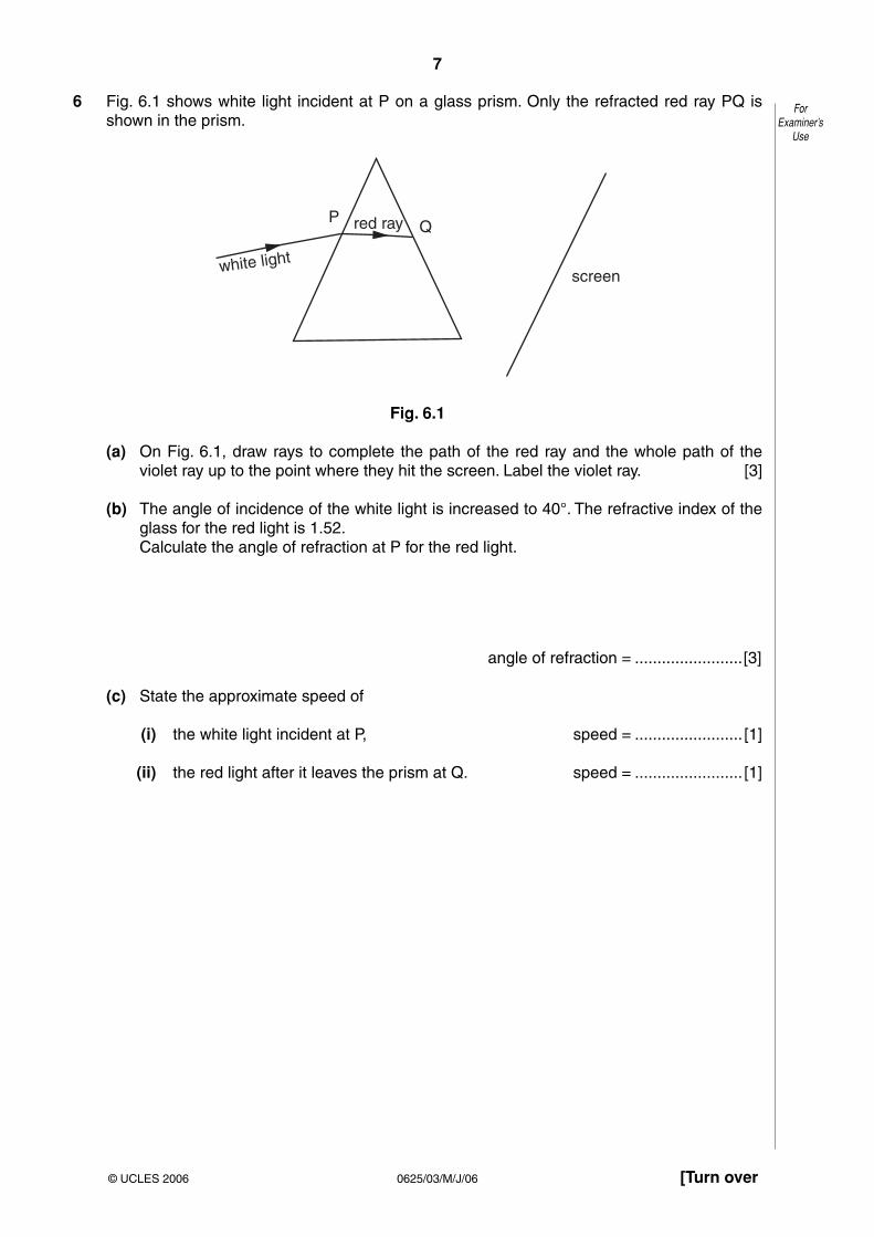
7
0625/03/M/J/06 [Turn over
ForExaminer’s
Use
© UCLES 2006
6 Fig. 6.1 shows white light incident at P on a glass prism. Only the refracted red ray PQ is shown in the prism.
PQ
white light
red ray
screen
Fig. 6.1
(a) On Fig. 6.1, draw rays to complete the path of the red ray and the whole path of the violet ray up to the point where they hit the screen. Label the violet ray. [3]
(b) The angle of incidence of the white light is increased to 40°. The refractive index of the glass for the red light is 1.52.
Calculate the angle of refraction at P for the red light.
angle of refraction = ........................[3]
(c) State the approximate speed of
(i) the white light incident at P, speed = ........................ [1]
(ii) the red light after it leaves the prism at Q. speed = ........................ [1]

8
0625/03/M/J/06
ForExaminer’s
Use
© UCLES 2006
7 Fig. 7.1 shows how the air pressure at one instant varies with distance along the path of a continuous sound wave.
air pressure
normalair pressure
P X Y
distance in directionof travel of the wave
Fig. 7.1
(a) What type of waves are sound waves?
......................................................................................................................................[1]
(b) On Fig. 7.1, mark on the axis PY
(i) one point C where there is a compression in the wave, [1]
(ii) one point R where there is a rarefaction in the wave. [1]
(c) Describe the motion of a group of air particles situated on the path of the wave shown in Fig. 7.1.
..........................................................................................................................................
..........................................................................................................................................
......................................................................................................................................[2]
(d) The sound wave shown has speed of 340 m / s and a frequency of 200 Hz. Calculate the distance represented by PX on Fig. 7.1.
distance = ........................[2]

9
0625/03/M/J/06 [Turn over
ForExaminer’s
Use
© UCLES 2006
8 Fig. 8.1 shows an electrical circuit.
12.0 V d.c.
4.0 Ω
R A C B
sliding contact
one metre resistance wire
Fig. 8.1
The resistance of the lamp is 4.0 Ω when it is at its normal brightness.
(a) The lamp is rated at 6.0 V, 9.0 W. Calculate the current in the lamp when it is at its normal brightness.
current = ........................[2]
(b) The sliding contact C is moved to A. The lamp lights at its normal brightness. Calculate
(i) the total circuit resistance,
resistance = ........................[1]
(ii) the potential difference across the 4.0 Ω resistor R.
potential difference = ........................[1]
(c) The sliding contact C is moved from A to B.
(i) Describe any change that occurs in the brightness of the lamp.
..............................................................................................................................[1]
(ii) Explain your answer to (i).
..................................................................................................................................
..............................................................................................................................[2]
(d) The 1 m wire between A and B, as shown in Fig. 8.1, has a resistance of 2.0 Ω. Calculate the resistance between A and B when
(i) the 1 m length is replaced by a 2 m length of the same wire,
resistance = ........................[1]
(ii) the 1 m length is replaced by a 1 m length of a wire of the same material but of only half the cross-sectional area.
resistance = ........................[1]

10
0625/03/M/J/06
ForExaminer’s
Use
© UCLES 2006
9 A transformer is needed to step down a 240 V a.c. supply to a 12 V a.c. output.
(a) In the space below, draw a labelled diagram of a suitable transformer. [3]
(b) Explain
(i) why the transformer only works on a.c.,
..................................................................................................................................
..............................................................................................................................[1]
(ii) how the input voltage is changed to an output voltage.
..................................................................................................................................
..................................................................................................................................
..............................................................................................................................[2]
(c) The output current is 1.5 A.
Calculate
(i) the power output,
power = ........................[1]
(ii) the energy output in 30 s.
energy = ........................[1]

11
0625/03/M/J/06 [Turn over
ForExaminer’s
Use
© UCLES 2006
10 (a) Fig. 10.1 shows a positively charged plastic rod, a metal plate resting on an insulator, and a lead connected to earth.
metal plate
insulator
positively chargedplastic rod
lead connected to earth
Fig. 10.1
Describe how the metal plate may be charged by induction.
..........................................................................................................................................
..........................................................................................................................................
......................................................................................................................................[3]
(b) An electrostatic generator sets up a current of 20 mA in a circuit.
Calculate
(i) the charge flowing through the circuit in 15 s,
charge = ............................
(ii) the potential difference across a 10 kΩ resistor in the circuit.
potential difference = ............................ [3]

12
0625/03/M/J/06
ForExaminer’s
Use
© UCLES 2006
11 Fig. 11.1 shows a beam of radiation that contains α-particles, β-particles and γ-rays. The beam enters a very strong magnetic field shown in symbol form by N and S poles.
beam ofradiation
N
S
Fig. 11.1
Complete the table below.
radiationdirection of deflection,
if anycharge carried byradiation, if any
α-particles
β-particles
γ-rays
[6]
Permission to reproduce items where third-party owned material protected by copyright is included has been sought and cleared where possible. Every reasonable effort has been made by the publisher (UCLES) to trace copyright holders, but if any items requiring clearance have unwittingly been included, the publisher will be pleased to make amends at the earliest possible opportunity.
University of Cambridge International Examinations is part of the University of Cambridge Local Examinations Syndicate (UCLES), which is itself a department of the University of Cambridge.

This document consists of 15 printed pages and 1 blank page.SPA (SJF3442/CG) S92054/2.1© UCLES 2005 [Turn over
UNIVERSITY OF CAMBRIDGE INTERNATIONAL EXAMINATIONS International General Certificate of Secondary Education
PHYSICS
Paper 3
0625/03
May/June 2005
1 hour 15 minutesCandidates answer on the Question Paper.No Additional Materials are required.
READ THESE INSTRUCTIONS FIRST
Write your Centre number, candidate number and name on all the work youhand in.Write in dark blue or black pen in the spaces provided on the Question Paper.You may use a soft pencil for any diagrams, graphs or rough working.Do not use staples, paper clips, highlighters, glue or correction fluid.
Answer all questions.At the end of the examination, fasten all your work securely together.The number of marks is given in brackets [ ] at the end of each question orpart question.You may lose marks if you do not show your working or if you do not useappropriate units.Take the weight of 1 kg to be 10 N (i.e. acceleration of free fall = 10 m/s2).
DO NOT WRITE IN THE BARCODE.
DO NOT WRITE IN THE GREY AREAS BETWEEN THE PAGES.
For Examiner’s Use
1
2
3
4
5
6
7
8
9
10
11
Total
Candidate
Name
Centre
Number
Candidate
Number

2
0625/03/M/J/05
1 A solid plastic sphere falls towards the Earth.
Fig. 1.1 is the speed-time graph of the fall up to the point where the sphere hits the Earth’ssurface.
Fig. 1.1
(a) Describe in detail the motion of the sphere shown by the graph.
..........................................................................................................................................
..........................................................................................................................................
..........................................................................................................................................
..........................................................................................................................................
..................................................................................................................................... [3]
0
20
P
Q
R S T
40
60
80
100
120
140
speedm / s
100 20 30 40 50 60 70 80 90 100 110time / s
ForExaminer’s
Use
© UCLES 2005
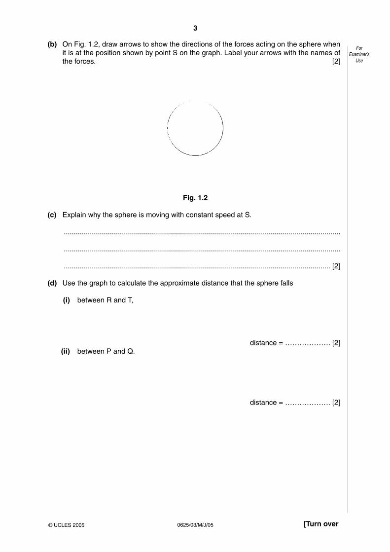
3
0625/03/M/J/05 [Turn over
(b) On Fig. 1.2, draw arrows to show the directions of the forces acting on the sphere whenit is at the position shown by point S on the graph. Label your arrows with the names ofthe forces. [2]
Fig. 1.2
(c) Explain why the sphere is moving with constant speed at S.
..........................................................................................................................................
..........................................................................................................................................
..................................................................................................................................... [2]
(d) Use the graph to calculate the approximate distance that the sphere falls
(i) between R and T,
distance = ………………. [2](ii) between P and Q.
distance = ………………. [2]
ForExaminer’s
Use
© UCLES 2005

4
0625/03/M/J/05
2 Fig. 2.1 shows a simple pendulum that swings backwards and forwards between P and Q.
Fig. 2.1
(a) The time taken for the pendulum to swing from P to Q is approximately 0.5 s.
Describe how you would determine this time as accurately as possible.
..........................................................................................................................................
..........................................................................................................................................
..................................................................................................................................... [2]
(b) (i) State the two vertical forces acting on the pendulum bob when it is at position R.
1. ...............................................................................................................................
2. .......................................................................................................................... [1]
(ii) The pendulum bob moves along the arc of a circle. State the direction of theresultant of the two forces in (i).
.............................................................................................................................. [1]
(c) The mass of the bob is 0.2 kg. During the swing it moves so that P is 0.05 m higher than R.
Calculate the increase in potential energy of the pendulum bob between R and P.
potential energy = ………………. [2]
support
string
pendulum bobP
RQ
ForExaminer’s
Use
© UCLES 2005

5
0625/03/M/J/05 [Turn over
3 A mass of 3.0 kg accelerates at 2.0 m/s2 in a straight line.
(a) State why the velocity and the acceleration are both described as vector quantities.
..........................................................................................................................................
..................................................................................................................................... [1]
(b) Calculate the force required to accelerate the mass.
force = ………………. [2]
(c) The mass hits a wall.The average force exerted on the wall during the impact is 120 N.The area of the mass in contact with the wall at impact is 0.050 m2.Calculate the average pressure that the mass exerts on the wall during the impact.
pressure = ………………. [2]
ForExaminer’s
Use
© UCLES 2005

6
0625/03/M/J/05
4 Fig. 4.1 shows apparatus that a student uses to make an estimate of the specific heatcapacity of iron.
Fig. 4.1
(a) The power of the heater is known. State the four readings the student must take to findthe specific heat capacity of iron.
1. ......................................................................................................................................
2. ......................................................................................................................................
3. ......................................................................................................................................
4. ................................................................................................................................. [3]
(b) Write down an equation, in words or in symbols, that could be used to work out thespecific heat capacity of iron from the readings in (a).
[2]
iron block
electrical heaterthermometer
ForExaminer’s
Use
© UCLES 2005

7
0625/03/M/J/05 [Turn over
(c) (i) Explain why the value obtained with this apparatus is higher than the actual value.
...................................................................................................................................
.............................................................................................................................. [1]
(ii) State one addition to the apparatus that would help to improve the accuracy of thevalue obtained.
...................................................................................................................................
.............................................................................................................................. [1]
ForExaminer’s
Use
© UCLES 2005

8
0625/03/M/J/05
5 (a) Fig. 5.1 shows the paths of a few air molecules and a single dust particle. The actual airmolecules are too small to show on the diagram.
Fig. 5.1
Explain why the dust particle undergoes small random movements.
..........................................................................................................................................
..........................................................................................................................................
..........................................................................................................................................
..................................................................................................................................... [4]
(b) Fig. 5.2 shows the paths of a few molecules leaving the surface of a liquid. The liquid isbelow its boiling point.
Fig. 5.2
(i) State which liquid molecules are most likely to leave the surface.
...................................................................................................................................
.............................................................................................................................. [1]
(ii) Explain your answer to (i).
...................................................................................................................................
...................................................................................................................................
.............................................................................................................................. [2]
air and vapour
liquid
dust particle
paths ofair molecules
ForExaminer’s
Use
© UCLES 2005

9
0625/03/M/J/05 [Turn over
6 Fig. 6.1 shows a ray of light OPQ passing through a semi-circular glass block.
Fig. 6.1
(a) Explain why there is no change in the direction of the ray at P.
..........................................................................................................................................
..................................................................................................................................... [1]
(b) State the changes, if any, that occur to the speed, wavelength and frequency of the lightas it enters the glass block.
..........................................................................................................................................
..........................................................................................................................................
..................................................................................................................................... [2]
(c) At Q some of the light in ray OPQ is reflected and some is refracted.
On Fig. 6.1, draw in the approximate positions of the reflected ray and the refracted ray.Label these rays. [2]
(d) The refractive index for light passing from glass to air is 0.67.
Calculate the angle of refraction of the ray that is refracted at Q into air.
angle = ………………. [3]
30°
Q
P
O
ForExaminer’s
Use
© UCLES 2005
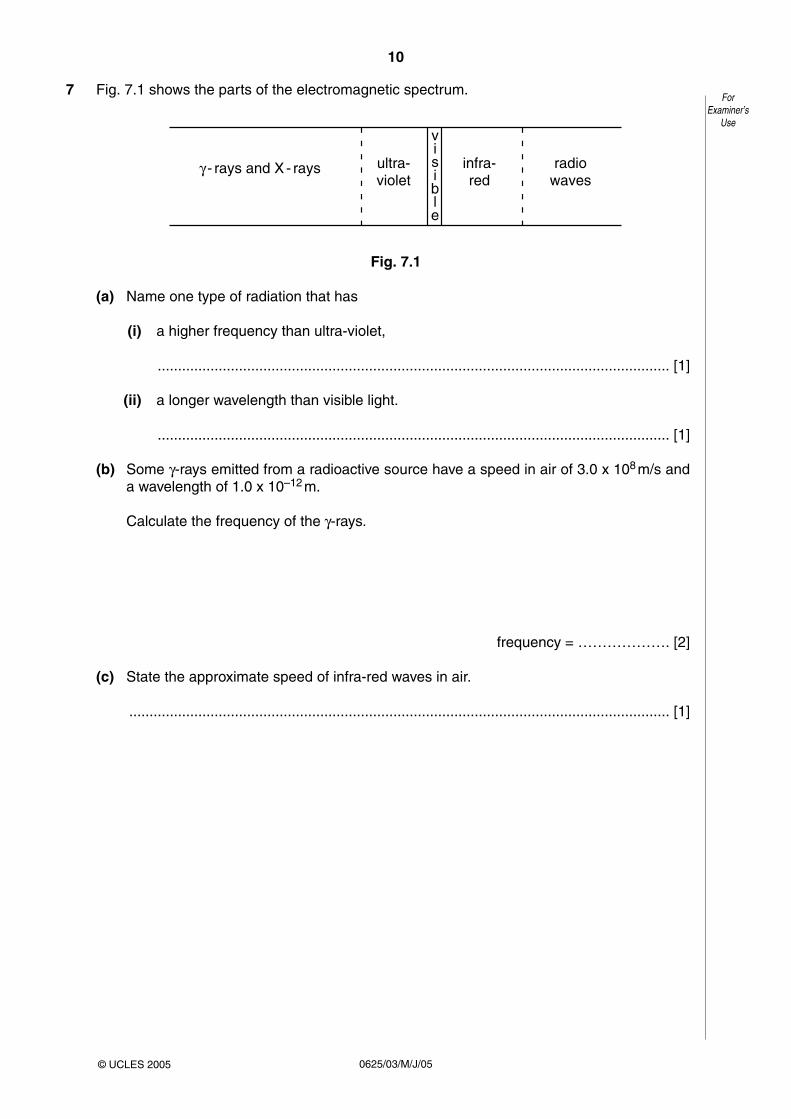
10
0625/03/M/J/05
7 Fig. 7.1 shows the parts of the electromagnetic spectrum.
Fig. 7.1
(a) Name one type of radiation that has
(i) a higher frequency than ultra-violet,
.............................................................................................................................. [1]
(ii) a longer wavelength than visible light.
.............................................................................................................................. [1]
(b) Some γ-rays emitted from a radioactive source have a speed in air of 3.0 x 10⁸ m/s anda wavelength of 1.0 x 10⁻¹² m.
Calculate the frequency of the γ-rays.
frequency = ………………. [2]
(c) State the approximate speed of infra-red waves in air.
..................................................................................................................................... [1]
γ - rays and X - rays ultra-violet
infra-red
radiowaves
visible
ForExaminer’s
Use
© UCLES 2005

11
0625/03/M/J/05 [Turn over
8 A student has a power supply, a resistor, a voltmeter, an ammeter and a variable resistor.
(a) The student obtains five sets of readings from which he determines an average valuefor the resistance of the resistor.
In the space below, draw a labelled diagram of a circuit that he could use.
[3]
(b) Describe how the circuit should be used to obtain the five sets of readings.
..........................................................................................................................................
..........................................................................................................................................
..................................................................................................................................... [2]
(c) Fig. 8.1 shows another circuit.
Fig. 8.1
When the circuit is switched on, the ammeter reads 0.50 A.
(i) Calculate the value of the unknown resistor.
resistance = ………………. [2]
(ii) Calculate the charge passing through the 3.0 Ω resistor in 120 s.
charge = ………………. [1]
(iii) Calculate the power dissipated in the 3.0 Ω resistor.
power = ………………. [2]
6.0 V
resistor3.0 Ω
resistor ofunknown value
A
ForExaminer’s
Use
© UCLES 2005

12
0625/03/M/J/05
9 (a) Fig. 9.1 shows an a.c. supply connected to a resistor and a diode.
Fig. 9.1
(i) State the effect of fitting the diode in the circuit.
...................................................................................................................................
.............................................................................................................................. [1]
(ii) On Fig. 9.2, sketch graphs to show the variation of the a.c. supply voltage and theoutput voltage with time.
Fig. 9.2[2]
(b) (i) In the space below, draw the symbol for a NOT gate.
[1]
(ii) State the action of a NOT gate.
...................................................................................................................................
...................................................................................................................................
.............................................................................................................................. [2]
a.c. supplyvoltage
time
time
0
0
outputvoltage
a.c. supply outputresistor
ForExaminer’s
Use
© UCLES 2005

13
0625/03/M/J/05 [Turn over
10 (a) Fig. 10.1 is the decay curve for a radioactive isotope that emits only β-particles.
Fig. 10.1
Use the graph to find the value of the half-life of the isotope.
Indicate, on the graph, how you arrived at your value.
half-life …………………………. [2]
(b) A student determines the percentage of β-particles absorbed by a thick aluminiumsheet. He uses a source that is emitting only β-particles and that has a long half-life.
(i) In the space below, draw a labelled diagram of the apparatus required, set up tomake the determination.
[2]
(ii) List the readings that the student needs to take.
...................................................................................................................................
...................................................................................................................................
...................................................................................................................................
.............................................................................................................................. [3]
0 10
100
0
200
300
400
20time / min
count ratecounts / min
30 40
ForExaminer’s
Use
© UCLES 2005

14
0625/03/M/J/05
11 Fig. 11.1 shows a flexible wire hanging between two magnetic poles. The flexible wire isconnected to a 12 V d.c. supply that is switched off.
Fig. 11.1
(a) Explain why the wire moves when the supply is switched on.
..........................................................................................................................................
..........................................................................................................................................
..................................................................................................................................... [2]
(b) State the direction of the deflection of the wire.
..........................................................................................................................................
..................................................................................................................................... [2]
(c) When the wire first moves, energy is changed from one form to another. State these twoforms of energy.
from ........................................................... to ............................................................ [1]
wire fixed here
wire fixed here
12 V d.c.+
N S–
flexible wire hangingbetween magnetic poles
ForExaminer’s
Use
© UCLES 2005

15
0625/03/M/J/05
(d) Fig. 11.2 shows the flexible wire made into a rigid rectangular coil and mounted on anaxle.
Fig. 11.2
(i) Add to the diagram an arrangement that will allow current to be fed into the coilwhilst allowing the coil to turn continuously. Label the parts you have added. [1]
(ii) Briefly explain how your arrangement works.
...................................................................................................................................
.............................................................................................................................. [2]
axle
magnetic pole
magnetic pole
axle
N N
S S
coil
ForExaminer’s
Use
© UCLES 2005

16
0625/03/M/J/05
BLANK PAGE
Permission to reproduce items where third-party owned material protected by copyright is included has been sought and cleared where possible. Everyreasonable effort has been made by the publisher (UCLES) to trace copyright holders, but if any items requiring clearance have unwittingly been included, thepublisher will be pleased to make amends at the earliest possible opportunity.
University of Cambridge International Examinations is part of the University of Cambridge Local Examinations Syndicate (UCLES), which is itself a department ofthe University of Cambridge.

This document consists of 13 printed pages and 3 blank pages.
SPA (NH/BI) S61207/2© UCLES 2004 [Turn over
UNIVERSITY OF CAMBRIDGE INTERNATIONAL EXAMINATIONS International General Certificate of Secondary Education
PHYSICS 0625/03
Paper 3May/June 2004
1 hour 15 minutesCandidates answer on the Question Paper.No Additional Materials are required.
READ THESE INSTRUCTIONS FIRST
Write your Centre number, candidate number and name on all the work you hand in.Write in dark blue or black pen in the spaces provided on the Question Paper.You may use a soft pencil for any diagrams, graphs or rough working.Do not use staples, paper clips, highlighters, glue or correction fluid.
Answer all questions.At the end of the examination, fasten all your work securely together.The number of marks is given in brackets [ ] at the end of each question or part question.You may lose marks if you do not show your working or if you do not use appropriate units.
Centre Number Candidate Number Name
If you have been given a label, look at thedetails. If any details are incorrect ormissing, please fill in your correct detailsin the space given at the top of this page.
Stick your personal label here, ifprovided.
For Examiner’s Use
1
2
3
4
5
6
7
8
9
10
11
Total

2
0625/03 M/J/04
1 Fig. 1.1 shows a cycle track.
Fig. 1.1
A cyclist starts at A and follows the path ABCDEB.
The speed-time graph is shown in Fig. 1.2.
Fig. 1.2
(a) Use information from Fig. 1.1 and Fig. 1.2 to describe the motion of the cyclist
(i) along AB,
...................................................................................................................................
(ii) along BCDEB.
...................................................................................................................................
...................................................................................................................................[4]
0
1
0
2
3
4
5
6
30 40 5010 20 60 70 80 90 100
time / s
speed m / s
A
B C D E B
A B
E C
D
v = 6 m/s
ForExaminer’s
Use
© UCLES 2004

3
0625/03 M/J/04 [Turn over
(b) The velocity v of the cyclist at C is shown in Fig. 1.1.
State one similarity and one difference between the velocity at C and the velocity at E.
similarity ...........................................................................................................................
difference ......................................................................................................................[2]
(c) Calculate
(i) the distance along the cycle track from A to B,
distance = …………………
(ii) the circumference of the circular part of the track.
circumference = …………………[4]
ForExaminer’s
Use
© UCLES 2004

4
0625/03 M/J/04
2 Fig. 2.1 shows a rock that is falling from the top of a cliff into the river below.
Fig. 2.1
(a) The mass of the rock is 75 kg. The acceleration of free fall is 10 m/s2.Calculate the weight of the rock.
weight = …………………[1]
(b) The rock falls from rest through a distance of 15 m before it hits the water.Calculate its kinetic energy just before hitting the water. Show your working.
kinetic energy = …………………[3]
(c) The rock hits the water. Suggest what happens to the kinetic energy of the rock duringthe impact.
..........................................................................................................................................
..........................................................................................................................................
......................................................................................................................................[3]
cliff
falling rock
river
ForExaminer’s
Use
© UCLES 2004
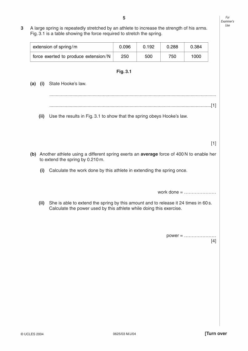
5
0625/03 M/J/04 [Turn over
3 A large spring is repeatedly stretched by an athlete to increase the strength of his arms.Fig. 3.1 is a table showing the force required to stretch the spring.
Fig. 3.1
(a) (i) State Hooke’s law.
...................................................................................................................................
...............................................................................................................................[1]
(ii) Use the results in Fig. 3.1 to show that the spring obeys Hooke’s law.
[1]
(b) Another athlete using a different spring exerts an average force of 400 N to enable herto extend the spring by 0.210 m.
(i) Calculate the work done by this athlete in extending the spring once.
work done = …………………
(ii) She is able to extend the spring by this amount and to release it 24 times in 60 s.Calculate the power used by this athlete while doing this exercise.
power = …………………[4]
ForExaminer’s
Use
© UCLES 2004
extension of spring/m 0.096 0.192 0.288 0.384
force exerted to produce extension/N 250 500 750 1000

6
0625/03 M/J/04
4 (a) Two identical open boxes originally contain the same volume of water.One is kept at 15 °C and the other at 85 °C for the same length of time.
Fig. 4.1 shows the final water levels.
Fig. 4.1
With reference to the energies of the water molecules, explain why the levels aredifferent.
..........................................................................................................................................
..........................................................................................................................................
..........................................................................................................................................
......................................................................................................................................[3]
(b) In an experiment to find the specific latent heat of vaporisation of water, it took 34 500 Jof energy to evaporate 15 g of water that was originally at 100 °C.
A second experiment showed that 600 J of energy was lost to the atmosphere from theapparatus during the time it took to evaporate 15 g of water.
Calculate the specific latent heat of vaporisation of water that would be obtained fromthis experiment.
specific latent heat = …………………[3]
85 °C15 °C
ForExaminer’s
Use
© UCLES 2004

7
0625/03 M/J/04 [Turn over
5 (a) Fig. 5.1 shows two identical metal plates. The front surface of one is dull black and thefront surface of the other is shiny silver.The plates are fitted with heaters that keep the surfaces of the plates at the sametemperature.
Fig. 5.1
(i) State the additional apparatus needed to test which surface is the best emitter ofheat radiation.
...................................................................................................................................
(ii) State one precaution that is needed to ensure a fair comparison.
...................................................................................................................................
...................................................................................................................................
(iii) State the result that you expect.
...................................................................................................................................
(iv) Write down another name for heat radiation.
...................................................................................................................................[4]
(b) In the space below, draw a labelled diagram of an everyday situation in which aconvection current occurs.
Mark the path of the current with a line and show its direction with arrows. [3]
dull black shiny silver
ForExaminer’s
Use
© UCLES 2004

8
0625/03 M/J/04
6 Fig. 6.1 shows a ray PQ of blue light incident on the side of a rectangular glass block.
Fig. 6.1
(a) (i) By drawing on Fig. 6.1, continue the ray PQ through and beyond the block.
(ii) Mark the angle of incidence at CD with the letter i and the angle of refraction at CDwith the letter r.
[3]
(b) The speed of light in air is 3.0 x 10⁸ m/s and the speed of light in glass is 2.0 x 10⁸ m/s.
(i) Write down a formula that gives the refractive index of glass in terms of thespeeds of light in air and glass.
refractive index =
(ii) Use this formula to calculate the refractive index of glass.
refractive index = …………………[2]
(c) The frequency of the blue light in ray PQ is 6.0 x 10¹⁴ Hz.Calculate the wavelength of this light in air.
wavelength = ……………..……[2]
A B
DCQ
P
glass
air
Fig. 6.1
ForExaminer’s
Use
© UCLES 2004
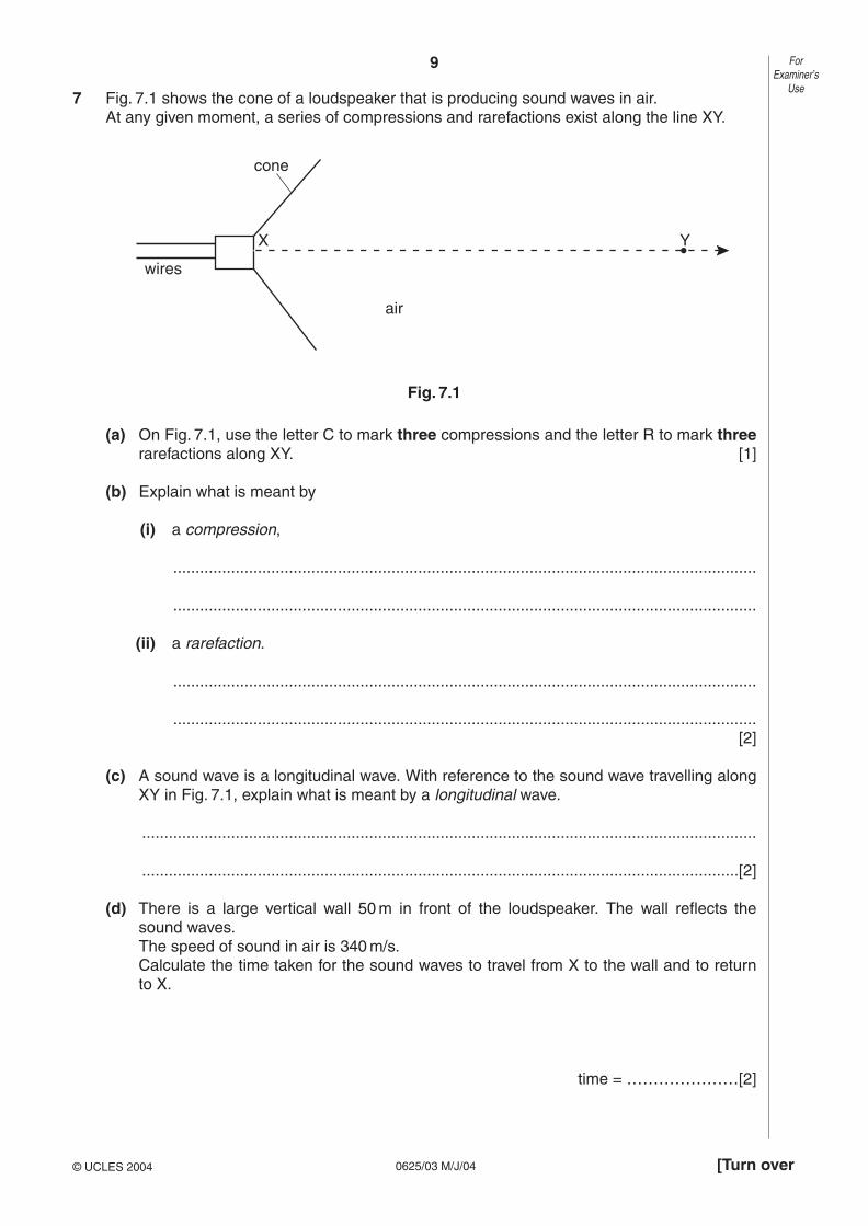
9
0625/03 M/J/04 [Turn over
7 Fig. 7.1 shows the cone of a loudspeaker that is producing sound waves in air.At any given moment, a series of compressions and rarefactions exist along the line XY.
Fig. 7.1
(a) On Fig. 7.1, use the letter C to mark three compressions and the letter R to mark threerarefactions along XY. [1]
(b) Explain what is meant by
(i) a compression,
...................................................................................................................................
...................................................................................................................................
(ii) a rarefaction.
...................................................................................................................................
...................................................................................................................................[2]
(c) A sound wave is a longitudinal wave. With reference to the sound wave travelling alongXY in Fig. 7.1, explain what is meant by a longitudinal wave.
..........................................................................................................................................
......................................................................................................................................[2]
(d) There is a large vertical wall 50 m in front of the loudspeaker. The wall reflects thesound waves.The speed of sound in air is 340 m/s.Calculate the time taken for the sound waves to travel from X to the wall and to return to X.
time = …………………[2]
air
cone
wires
X Y
ForExaminer’s
Use
© UCLES 2004

10
0625/03 M/J/04
8 Fig. 8.1 shows a 240 V a.c. mains circuit to which a number of appliances are connected andswitched on.
Fig. 8.1
(a) Calculate the power supplied to the circuit.
power = …………..[1]
(b) The appliances are connected in parallel.
(i) Explain what connected in parallel means.
...................................................................................................................................
...................................................................................................................................
(ii) State two advantages of connecting the appliances in parallel rather than in series.
advantage 1 ...............................................................................................................
advantage 2 ...............................................................................................................[3]
(c) Calculate
(i) the current in the refrigerator,
current = …………..
(ii) the energy used by the fan in 3 hours,
energy = …………..
(iii) the resistance of the filament of one lamp.
resistance = …………..[7]
1.2 kW 200 W60 W 60 W
refrigeratorfan240 V a.c.
ForExaminer’s
Use
© UCLES 2004

11
0625/03 M/J/04 [Turn over
9 Electromagnetic induction can be demonstrated using a solenoid, a magnet, a sensitiveammeter and connecting wire.
(a) In the space below, draw a labelled diagram of the apparatus set up to demonstrateelectromagnetic induction. [2]
(b) State one way of using the apparatus to produce an induced current.
..........................................................................................................................................
......................................................................................................................................[1]
(c) Explain why your method produces an induced current.
..........................................................................................................................................
..........................................................................................................................................
......................................................................................................................................[2]
(d) Without changing the apparatus, state what must be done to produce
(i) an induced current in the opposite direction to the original current,
...................................................................................................................................
...................................................................................................................................
(ii) a larger induced current.
...................................................................................................................................
...................................................................................................................................[2]
ForExaminer’s
Use
© UCLES 2004

12
0625/03 M/J/04
10 (a) Fig. 10.1 shows the faces of two ammeters. One has an analogue display and the othera digital display.
Fig. 10.1
State what is meant by the terms analogue and digital.
..........................................................................................................................................
..........................................................................................................................................
......................................................................................................................................[2]
(b) (i) Name the components from which logic gates are made.
...............................................................................................................................[1]
(ii) In the space below, draw the symbol for an AND gate.Label the inputs and the output. [1]
(iii) Describe the action of an AND gate with two inputs. [2]
2 34
5
1
0
AA
ForExaminer’s
Use
© UCLES 2004

13
0625/03 M/J/04
11 (a) α-particles can be scattered by thin gold foils.
Fig. 11.1 shows part of the paths of three α-particles.Complete the paths of the three α-particles. [3]
Fig. 11.1
(b) What does the scattering of α-particles show about atomic structure?
..........................................................................................................................................
..........................................................................................................................................
......................................................................................................................................[2]
(c) State the nucleon number (mass number) of an α-particle.
nucleon number = …………………[1]
α-particle 1
α-particle 2
α-particle 3
gold nuclei
ForExaminer’s
Use
© UCLES 2004

14
0625/03 M/J/04
BLANK PAGE

15
0625/03 M/J/04
BLANK PAGE

16
0625/03 M/J/04
BLANK PAGE
University of Cambridge International Examinations is part of the University of Cambridge Local Examinations Syndicate (UCLES), which is itself a department ofthe University of Cambridge.