UNIVERSITY OF CAMBRIDGE INTERNATIONAL … · First Variant Question Paper UNIVERSITY OF CAMBRIDGE...
16
First Variant Question Paper UNIVERSITY OF CAMBRIDGE INTERNATIONAL EXAMINATIONS International General Certificate of Secondary Education CANDIDATE NAME c- ~-- ~ _ltn,slPt!r [IJ]=O CENTRE NUMBER CANDIDATE NUMBER -----l [ '--j PHYSICS 0625/31 Paper 3 Extended October/November 2008 - ~ _ Candidates answer on the Question Paper. -= r No Additional Materials are required. READ THESE INSTRUCTIONS FIRST Write your Centre number, candidate number and name on all the work you hand in. Write in dark blue or black pen. You may use a soft pencil for any diagrams, graphs or rough working. Do not use staples, paper clips, highlighters, glue or correction fluid. DO NOT WRITE IN ANY BARCODES. Answer all questions. You may lose marks if you do not show your working or if you do not use appropriate units. Take the weight of 1 kg to be 10 N (i.e. acceleration of free fall = 10 rn/s-') At the end of the examination, fasten all your work securely together. The number of marks is given in brackets [ 1 at the end of each question or part question. SPA (SHW 00014 3/07) T50468/5 © UCLES 2008 This document consists of 16 printed pages. V=Jll :'\IVI-I(SIT) "I C-'lMI:lI{IDCE V lnrcrn.u ion.il r'\,lllllll,llillm 1 hour 15 minutes [Turn over Hany El-Gezawy
Transcript of UNIVERSITY OF CAMBRIDGE INTERNATIONAL … · First Variant Question Paper UNIVERSITY OF CAMBRIDGE...

First Variant Question Paper
UNIVERSITY OF CAMBRIDGE INTERNATIONAL EXAMINATIONSInternational General Certificate of Secondary Education
CANDIDATENAME c- ~--~_ltn,slPt!r
[IJ]=OCENTRENUMBER
CANDIDATENUMBER
-----l[ '--j
PHYSICS 0625/31
Paper 3 Extended October/November 2008-~ _ Candidates answer on the Question Paper.-=r No Additional Materials are required.
READ THESE INSTRUCTIONS FIRST
Write your Centre number, candidate number and name on all the work you hand in.Write in dark blue or black pen.You may use a soft pencil for any diagrams, graphs or rough working.Do not use staples, paper clips, highlighters, glue or correction fluid.DO NOT WRITE IN ANY BARCODES.
Answer all questions.You may lose marks if you do not show your working or if you do not use appropriate units.Take the weight of 1 kg to be 10 N (i.e. acceleration of free fall = 10 rn/s-')
At the end of the examination, fasten all your work securely together.The number of marks is given in brackets [ 1 at the end of each question or part question.
SPA (SHW 00014 3/07) T50468/5© UCLES 2008
This document consists of 16 printed pages.
V=Jll :'\IVI-I(SIT) "I C-'lMI:lI{IDCE
V lnrcrn.u ion.il r'\,lllllll,llillm
1 hour 15 minutes
[Turn over
Hany El-Gezaw
y

-_•.....,., /
2
Fig. 1.1 shows apparatus used to find a relationship between the force applied to a trolleyand the acceleration caused by the force.
stringtrolley
ticker-tape roll of tape
ticker-tapetimer
hanging mass runway
Fig. 1.1
For each mass, hung as shown, the acceleration of the trolley is determined from the tape.Some of the results are given in the table below.
weight of the hanging mass/N acceleration of the trolle~rn/s?
0.20
0.40
0.70
0,80 1.0
0.25
0.50
(a) (i) Explain why the trolley accelerates .
...... ."fi~ f? ..l.tE.f. / ~ t~,£;jht ................. , .. ~ .. , .-+P ... if. $.., Wf!,'.j.h..t wh;~'u~~.,,) ..,frJ~~f1~., [2]
(ii) Suggest why the runway has a slight slope as shown .
....................j-O ~~~f!, (.f.=>~~V1S.~J. ........... ..fr.;c..~\o~ h~.. . [1]
(b) Calculate the mass of the trolley, assuming that the accelerating force is equal to theweight of the hanging mass.
F..:: mamore ~/a
= 2/ !/.5
mass = ....Q..·.s [2]
© UCLES 2008 0625/31/0/N/08
ForExaminers
Use
Hany El-Gezaw
y
3
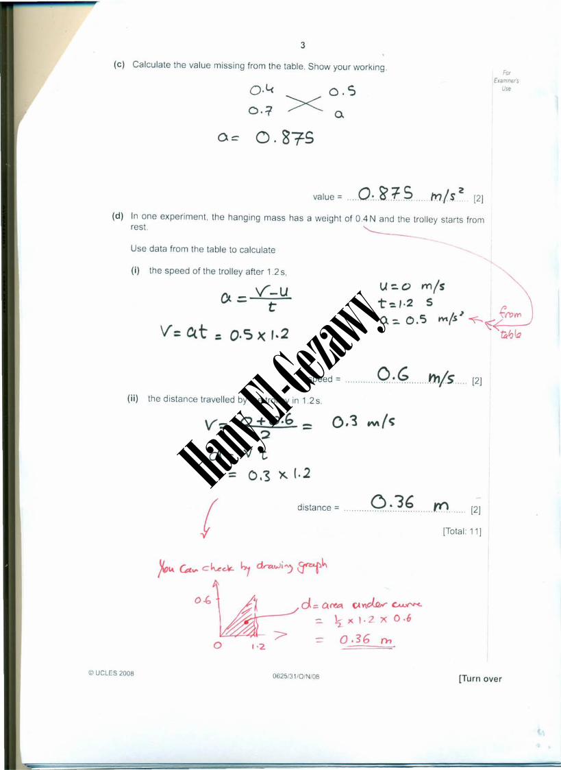
(e) Calculate the value missing from the table. Show your working.
o·l<
0.=1O.S>< 0.
ForIExaminers
Use
Oc (). 8-:rS
value = .....O.~~..1:S ....mls~ [2]
(d) In one experiment, the hanging mass has a weight of 0.4 N and the trolley starts fromrest.
Use data from the table to calculate
(i) the speed of the trolley after 1.2 s,
,..._ V-Uv-- t
V = C(t = o.s >( ,.2
U:.0 mlst-=.I.2 5Q::. O. '5 t'YIls ~ --(--- ~ _
speed = Q ~ .,,!s. [2]
(ii) the distance travelled by the trolley in 1.2 s.
v= 0+0.6 =2
d-;:vt= 0.'5 X 1.2
f distance = ..... O..~J.~.....m...[2]
[Total 11]
O·b
o
d:: Cl N'.e\ C.t ncl.!ur Cu.'i"I"<-
- ~ x !- Z X O.1l
'> 0.36 rn1·2.
© UCLES 2008 0625/31/0/N/08 [Turn over
Hany El-Gezaw
y

2 Fig. 2.1 shows a circular metal disc of mass 200 g, freely pivoted at its centre. ForExammer's
Use
4
pivot
o
Or OX\ Y w;t"t;i 3Dodra110Yl Yl\ ~j d\·drRu.~<;'
Fig. 2.1
Masses of 100g, 200g, 300g, 400g, 500g and 600g are available, but only one of eachvalue. These may be hung with string from any of the holes. There are three small holes oneach side of the centre, one at 4.0cm from the pivot, one at 8.0cm from the pivot and one at12.0cm from the pivot.
(a) On Fig. 2.1, draw in two different value masses hanging from appropriate holes. Thevalues of the masses should be chosen so that there is no net moment. Alongside themasses chosen, write down their values. [2]
The apparatus is to be used to show that there is no net moment of force acting on a bodywhen it is in equilibrium.
............................ Ot.;.~.c... W.:.IJ no.t r.'ofa.L .......... <.. .•"' ~"' •.I•.b.r.iv.mJ
(b) Explain how you would test that your chosen masses give no net moment to the disc .
................. [1]
(c) Calculate the moments about the pivot due to the two masses chosen.
F )( d=- (0.2'" ~ '0) X. \'2 em
2l-.t N ,en,().Y"\-; cl oc.1t.. Witf. MO~ :: (0.3 k, X \0) x 8CxYt
=- 2~ t\J. ~
.~.~ N.r.. Crn ..moment due to second mass = -2.L.c.. ....l'J .•.t..b,.
[2]
clock. wise. mom~\f\t =
moment due to first mass =
© UCLES 2008 0625/31/0/N/08
Hany El-Gezaw
y

(d) Calculate the force on the pivot when the two masses chosen are hanging from thedisc. For
ExaminersUse
5
\)~ toVCQ ~ :! cto~~ ~(~(= 2N +2N+ '"! ~
force = ..7t N [2]
[Total 7]
© UCLES 200B 0625/31/0/N/OB [Turn over
Hany El-Gezaw
y

(ii) the total pressure on the submarine at a depth of 70 m.
-t-",fa1 prt" II~ c: w"J...r ('lI'tsI'V ~ 1" a1'fh. fr 0""' Vicd-r., ~u~~
~ (-=t-. 35 X 10C; ) ~ ( i.o X \ 0s)total pressure =."~.3?.XI.O~ ... PCc..,, [1)
6
3 (a) A submarine descends to a depth of 70 m below the surface of water.
The density of the water is 1050 kg/m3. Atmospheric pressure is 1.0 x 10⁵ Pa.
Calculate,
I
(i) the increase in pressure as it descends from the surface to a depth of 70 m,
P:: f 9 h= 1050 x '0 'X =10 5increase in pressure =""'7.~3..s"..x.JO".PQ,, [2)
(b) On another dive, the submarine experiences a total pressure of 6.5 x 10⁵Pa. A hatchcover on the submarine has an area of 2.5 m2-Calculate the force on the outside of the cover.
?: ~!A~=- 'P xA
_ (;.c:, x lOS 'X 2.5 ,force = "" . .1·.6.~.S"".)(.JP..N [2)
(c) The submarine undergoes tests in fresh water of density 1000 kq/rn:'.
Explain why the pressure on the submarine is less at the same depth .
...................B~~ ••.......6if deJl)$;~ i.' Le.ss ."""."~"""G..".fr.t..tItJ..~"~.O~." ..~/ ..3,,.fMJ.,,h). [1)
[Total: 6)
© UCLES 2008 0625/31/0/N/08
ForExaminer's
Use
Hany El-Gezaw
y

4 The whole of a sealed, empty, dusty room is kept at a constant temperature of 15 "C Lightshines into the room through a small outside window.
ForExammer's
Use
7
An observer points a TV camera with a magnifying lens into the room through a secondsmall window, set in an inside wall at right angles to the outside wall.
Dust particles in the room show up on the TV monitor screen as tiny specks of light
(a) In the space below draw a diagram to show the motion of one of the specks of light overa short period of time.
[1]
(b) After a period of one hour the specks are still observed, showing that the dust particleshave not fallen to the floor.
Explain why the dust particles have not fallen to the floor. You may draw a labelleddiagram to help your explanation .
.........................~.'r: mo.le.w.JJ..s. h•.f ..~t.. pfArfick.s. in ......................cd/. dia.dlbtt.s ..'( (TI.O.Vt:. ..it...ill ..aIf .dirrdi'onr)
.j~t a.s ..e.Ke.ly. ..To kI!. UP..Q.~ $~w. .
................ " " [2]
(c) On another day, the temperature of the room is only 5°e All other conditions are thesame and the specks of light are again observed.
Suggest any differences that you would expect in the movement of the specks when thetemperature is 5°e, compared to before .
....................a.s +!.f!P!.rn:Ju~ ..d(Crfasd.·,,/Gf··da: rea.szJ ...
................. .so. '.I.c:bnolom ..mo 'If!1YtIenfs ~/..J.J.be s.DJII./ler.. ....................... [1]
[Total: 4]
© UCLES 2008 0625/31/0/N/08 [Turn over
Hany El-Gezaw
y

5
8
Fig. 5.1 shows apparatus that could be used to determine the specific latent heat of fusion ofice. For
ExaminersUse
stand with clamps to hold1 ~I r funnel and heater
tid r-----"-'------
40 W electric heater
finely crushed ice
glass funnel
Fig. 5.1
(a) In order to obtain as accurate a result as possible, state why it is necessary to
(i) wait until water is dripping into the beaker at a constant rate before takingreadings,
................h~tJ.tr...r::elA.cIu.J m4/X temp. ... tuM.e1 n:Q..~r.J; /.;~ ..heJ. .t: L~e .
(ii) use finely crushed ice rather than large pieces .
[1)
......rttS;dt. ...()l.laf!<..pi,.r~.5..(J:)fAIJ ....~ ...t,Jel.. ..h.tJt:J.fAJ ....ca.pO;J,1-
...b.~ be1ftt': r.orlt'acl be:1lvtt.n hedly. ..flNi..£u..... [1)
(b) The power of the heater and the time for which water is collected are known. Write downall the other readings that are needed to obtain a value for the specific latent heat offusiOn of ice .
........mQs.!i. ..of beQ.~y' .{.~m(JIyJ .
.......",(us: of ..hea kt.~ +..wtdt-r: .(nor (}'ltHS ryf w~ 0 r: m(,lU ~ i.ce...)
$ ~~ CAn ,.,or hz ofrl-tA.t~.A ~ V'tA.c{.'t.)'
, cPu, cat') !:ut, cd~ ,(hm ~ A~~ rear1i~f I
© UCLES 2008 0625/31/0/N/08
[2)
Hany El-Gezaw
y

9
(c) Using a 40W heater, 16.3g of ice is melted in 2.0 minutes. The heater is then switchedoff. In a further 2.0 minutes, 2.1 g of ice is melted. For
ExammersUse
Calculate the value of the specific latent heat of fusion of ice from these results.
mass J lee roetttJ , htcdef =.16.3 _ 2.1= 1'-.·2 -9 .........•..O. O}~2 ~
6t. t;. = HeJ~.to:: /20 -s
('P )(t ::. m LC J!to X 12.0 = O.Ollot2 X Lf
L 40 X 12v+ - 0.01'-<2-
specific latent heat of fusion of ice = ~.~.Sl9~r...Jj.~4]
[Total 8]
-- rn It14·2.)( L.t
_40X120- -----'L,.2'33~
--
-- J/j
© UCLES 20080625/31/0/NIOS [Turn over
Hany El-Gezaw
y
10
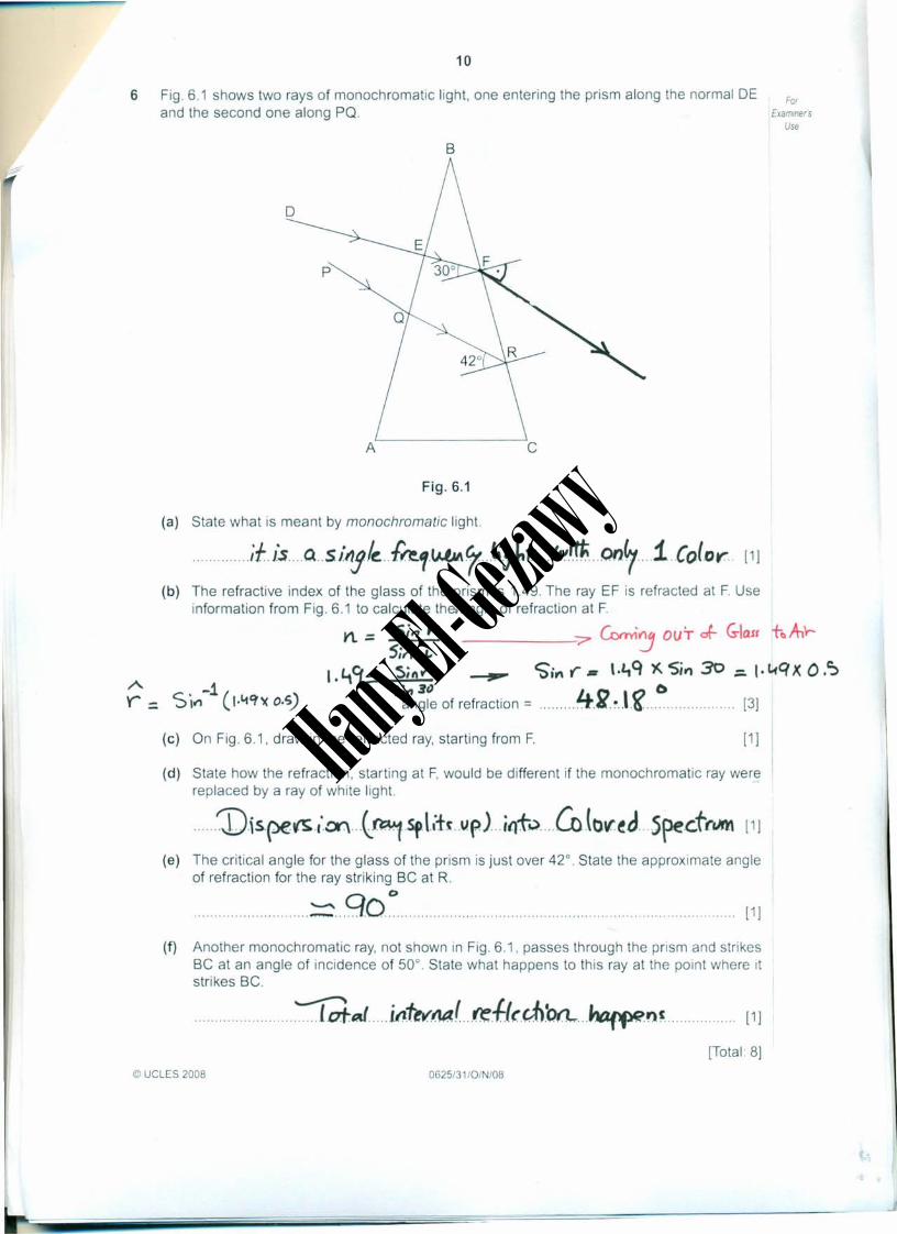
6 Fig. 6.1 shows two rays of monochromatic light. one entering the prism along the normal DEand the second one along PO.
ForExammers
Use
B
Fig.6.1
(a) State what is meant by monochromatic light .
...... ,if, is....Q. SlllJ·le.· {fe.1·WNt 7' .t-,l.t ...lAIi~ ..on.'7 ....1 (o(or [1]
(b) The refractive index of the glass of the prism is 1.49. The ray EF is refracted at F. Useinformation from Fig. 6.1 to calculate the.anqle of refraction at F.
n. = Sit? r == Grviy OUT ot- Glast to A,'r-5il1 i.
\.!.tCf:= 5;,,"- .-"... CSil"l r. l.l1Q )(. Sit\ 30 ::. I·l.(qx O.~'Sin 3" 4n ,0 0
angle of refraction = .. ,4.~ 6 . [3]
(c) On Fig. 6.1. draw in the refracted ray. starting from F. [1]
(d) State how the refraction. starting at F. would be different if the monochromatic ray werereplaced by a ray of white light.
......V.ispe~.,.0f) ...(~.Sf.\ •.tt ..v.pJ ..;{}t-.) ....COlbv~d...5pe.c.trUM [1]
(e) The critical angle for the glass of the prism is just over 42°. State the approximate angleof refraction for the ray striking Be at R.
...........................~ ...go~. , , , ,.. ,............ [1]
(f) Another monochromatic ray. not shown in Fig. 6.1. passes through the prism and strikesBe at an angle of incidence of 50°. State what happens to this ray at the point where Itstrikes Be.
......................~tJ i"'tt~M.r.,.ref((dl'orL..~~, [1]
[Total 8]© UCLES 2008 0625/31/0/N/08
Hany El-Gezaw
y

7 Fig. 7.1 shows a scale drawing of plane waves approaching a gap in a barrier.For
ExaminersUse
11
direction of travelof plane waves
barrier
/
Same.. vvave ~1tiCE'",i~ ~ Curvutuve
of QrcS" 0...1- CeV11noP-3~
Fig. 7.1
(a) On Fig. 7.1, draw in the pattern of the waves after they have passed the gap. [3]
(b) The waves approaching the barrier have a wavelength of 2.5cm and a speed of 20cm/s.Calculate the frequency of the waves.
v= ~.f=- ~pted =
wa~~Om!.,
0'('"'
O·20 rv-./s0.02S m
frequency = g H2; [2]
(c) State the frequency of the diffracted waves .
......................................2 H~ . . .... [1]
[Total: 6]
© UCLES 2008 0625/31/0/N/08 [Turn over
Hany El-Gezaw
y
12
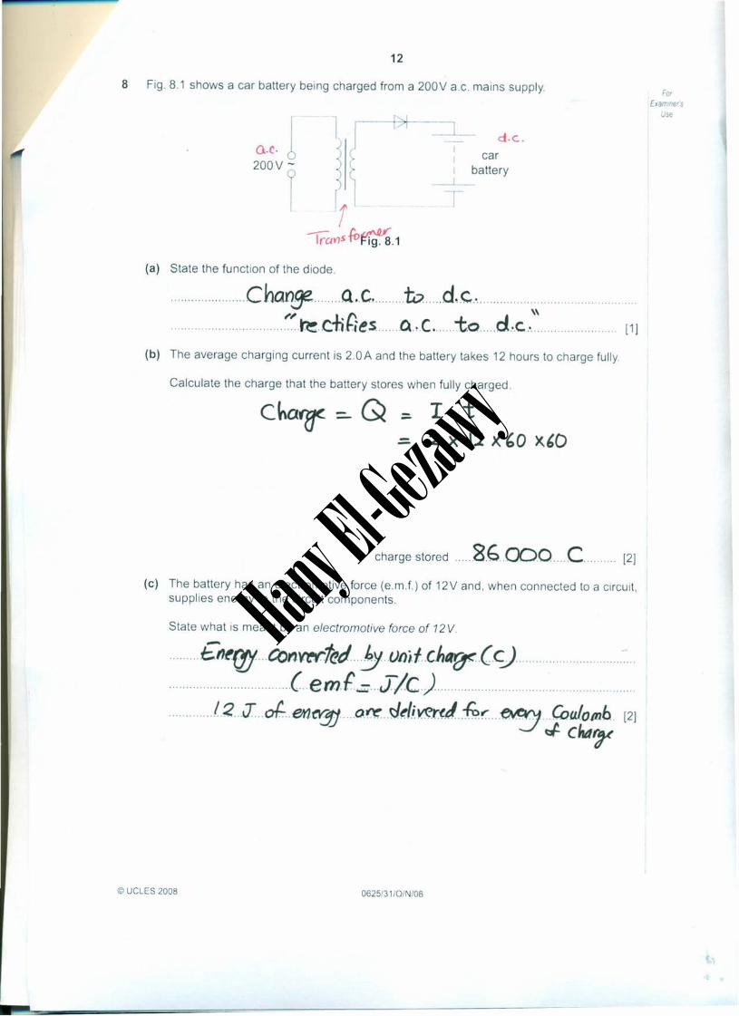
8 Fig. 8.1 shows a car battery being charged from a 200V a.c. mains supply.
a.c.1200V f
d·c.car
battery
ig.8.1
(a) State the function of the diode .
......................ChQn~ a..c to d,c ."............................~'..~.c:+;Hes....Q.,.C..to .d ..c. ...
(b) The average charging current is 2.0A and the battery takes 12 hours to charge fully.
Calculate the charge that the battery stores when fully charged.
Cha7f =- Q :
charge stored .....8.6 .cX)o ....C...... [2]
(c) The battery has an electromotive force (e.m.f.) of 12V and, when connected to a circuit,supplies energy to the circuit components.
State what is meant by an electromotive force of 12 V.
.........£n~rg con~1ed..5..vnj.f ..c.hfArF.(c) .
...................................c..em.£.:= ..J/C.) .
.............1.2...J...of....et1~ .....o.~ ..~rl;~r.(!/...-&~ ~ ..Coll.IO/llb. [2]
Jch4rr
© UCLES 2008 0625/31/0/N/08
ForExaminers
Use
[1]
Hany El-Gezaw
y

13
(d) (i) In the space below, draw a circuit diagram to show how two 6.0V lamps should beconnected to a 12V battery so that both lamps glow with normal brightness. [1 J
Sul~tG"'---1.-_,12 V SO\A.t"~
ForExamIners
Use
Series Connecbbn6v 6v
(ii) The power of each lamp is 8.0W Calculate the current in the circuit.
p= V. I.I: P/v =
or~~on,1 ~ --:: Rti .: '.'33A
16 W/,2V -= J·33
current = 1~..~.3A ... [2J
(iii) Calculate the energy used by the two lamps when both are lit for one hour.
t=- i h= ('0 )(60 =- 3600 s
s , t= xtor E =- V)( 1. X t
Oy:::. 12 X- 16
'.31 X 3600X '3600
energy = 5"7.~QQ.J [2]
[Total: 10]
© UCLES 2008 0625/31/0/N/08 [Turn over
Hany El-Gezaw
y
14
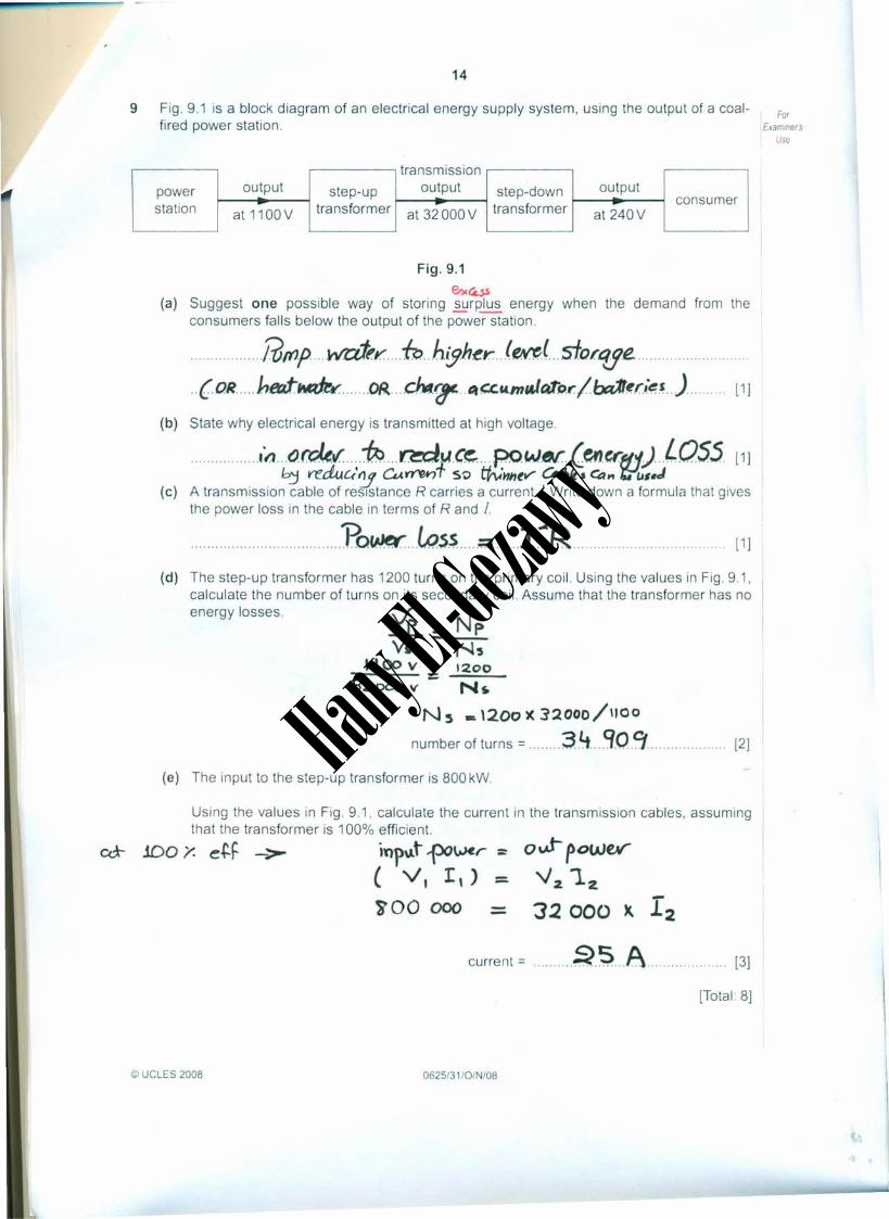
9 Fig. 9.1 is a block diagram of an electrical energy supply system, using the output of a coal-fired power station.
transmissionpower output step-up output step-down outputstation tra nsformer transformer
consumerat 1100 V at 32 OOOV at 240V
Fig. 9.1e.,.t£.ss
(a) Suggest one possible way of storing surplus energy when the demand from theconsumers falls below the output of the power station .
.........@mp wa:J;':' -6,..h.{Jht!r. ...le~J. sfor.'lJi! ...(OR hf!rit~ OR. chtl.~ ..lit "u.mtJt4'ru: Ibt::r1I.~d~~..)..........[1 J
(b) State why electrical energy is transmitted at high voltage .
...................n.b~~~J!:~r;;!f;;~':!r;.{t:4':'IJ!.}OSS[1]
(c) A transmission cable of resistance R carries a current 1.Write down a formula that givesthe power loss in the cable in terms of Rand 1.
p t : -2n........................................O~ w..s$ ;:;; l ~ [1J
(d) The step-up transformer has 1200 turns on the primary coil. Using the values in Fig. 9.1,calculate the number of turns on its secondary coil. Assume that the transformer has noenergy losses. \h N..:e.. - p
Vs - N,1100 v _ 1200
32000 v - N~
Ns & \200)( 32000/1100
number of turns = 3.Lt Q.O.9 [2J
(e) The input to the step-up transformer is 800 kW.
Using the values in Fig. 9.1, calculate the current in the transmission cables, assumingthat the transformer is 100% efficient.
.100 y. e~F -> iYlp\.lt ~\,Jer :
( VI II) =iOO 000
ovt-powe¥"2 '12
32000 X 12current = ..Q.~..A [3J
[Total: 8J
© UCLES 2008 0625/31/0/N/08
ForExamlner's
Use
Hany El-Gezaw
y

15
10 Fig. 10.1 shows a circuit for a warning lamp that comes on when the external light intensityfalls below a pre-set level.
ForExammers
Use
y+
xlow voltage
supply
Fig. 10.1
(a) On Fig. 10.1, label
(i) with the letter X the component that detects the change in external light intensity,
(ii) with the letter Y the lamp,
(iii) with the letter Z the component that switches the lamp on and off.[3]
(b) Describe how the circuit works as the external light intensity decreases and the lampcomes on .
................CU l'J bt.il2-1bJ.si!; de creases ........................K.e.s'~s.+anf.f of LD.R bfU""'.C( h~h .............50 L.D.R ;Je.t$. f2~~~y...s.barr.fJl tk V;lt1r......................c..,.J. ;.t ~( ..n.O/AJ ku,,' VO.flztr····i~ ..........................;.t~ GrC(M=t (.ba.S.~....~.t-ban' J:sfo.f::)
..........Iran.S;. j .tor. 5w..i.t-c&'e~ 0 tv.. .
......... ~r.."s ~.mp oN [3]
[Total: 6]
© UCLES 2008 0625/31/0/N/08 [Turn over
Hany El-Gezaw
y

16
11 Fig. 11.1 shows the basic design of the tube of a cathode ray oscilloscope (CRO).
A
B Y- plates
ForExamme(s
Use
)(- plate.s
cathode rays
o .fi. 5crteo
Fig.11.1
(a) On Fig. 11.1, write the names of parts A, B, C and 0 in the boxes provided. [2]
(b) State the function of:
part A, .J?~.I~i·"1···~·(t,'~tl~.. krytkr-miOlli'.....e.mtSS;Of.\ .
part B. ... ..HOVe. . ~ .. eJ~c.~be.(Urt .Ver.ttC'ally .[2]
(c) A varying p.d. from a 12V supply is connected to a CRO, so that the waveform of thesupply is shown on the screen.
To which of the components in Fig 11.1
(i) is the 12V supply connected,
...............................y ~ ..p.lat~s . [1]
(ii) is the time-base connected?
...x ..~ plca.tt.s . [1]
[Total: 6]
Permission 10 reproduce uerns where third-party owned material protected by copynqht IS Included has been soughl and cleared where possibleEvery reasonable efforl has been made by Ihe publisher (UCLES) 10 Irace copynghl holders. but rf any items requrnnq clearance have unwillingly been 'Included Ihe publisher will be pleased 10make amends at Ihe oarliest possible opporturuty
Uruversuy of Cambridge International Examinations IS part of the Cambridge Assessment Group Cambridge Assessment IS the brand name of Universityof Cambndge Local Examinalions Syndicate (UCLES). which ISusen a deparlmenl of the uruversitv of Cambndge
© UCLES 2008 0625/31/0/N/08
Hany El-Gezaw
y