
University Micrriffilms International - Arizona Campus Repository
216
Man to machine, machine to machine and machine to instrument interfaces for teleoperation of a fluid handling laboratory Item Type text; Thesis-Reproduction (electronic) Authors Hack, Byron Wallis John, 1963- Publisher The University of Arizona. Rights Copyright © is held by the author. Digital access to this material is made possible by the University Libraries, University of Arizona. Further transmission, reproduction or presentation (such as public display or performance) of protected items is prohibited except with permission of the author. Download date 15/03/2022 01:47:38 Link to Item http://hdl.handle.net/10150/276764
Transcript of University Micrriffilms International - Arizona Campus Repository

Man to machine, machine to machineand machine to instrument interfaces for
teleoperation of a fluid handling laboratory
Item Type text; Thesis-Reproduction (electronic)
Authors Hack, Byron Wallis John, 1963-
Publisher The University of Arizona.
Rights Copyright © is held by the author. Digital access to this materialis made possible by the University Libraries, University of Arizona.Further transmission, reproduction or presentation (such aspublic display or performance) of protected items is prohibitedexcept with permission of the author.
Download date 15/03/2022 01:47:38
Link to Item http://hdl.handle.net/10150/276764

INFORMATION TO USERS
This reproduction was made from a copy of a document sent to us for microfilming. While the most advanced technology has been used to photograph and reproduce this document, the quality of the reproduction is heavily dependent upon the quality of the material submitted.
The following explanation of techniques is provided to help clarify markings or notations which may appear on this reproduction.
1.The sign or "target" for pages apparently lacking from the document photographed is "Missing Page(s)". If it was possible to obtain the missing page(s) or section, they are spliced into the film along with adjacent pages. This may have necessitated cutting through an image and duplicating adjacent pages to assure complete continuity.
2. When an image on the film is obliterated with a round black mark, it is an indication of either blurred copy because of movement during exposure, duplicate copy, or copyrighted materials that should not have been filmed. For blurred pages, a good image of the page can be found in the adjacent frame. If copyrighted materials were deleted, a target note will appear listing the pages in the adjacent frame.
3. When a map, drawing or chart, etc., is part of the material being photographed, a definite method of "sectioning" the material has been followed. It is customary to begin filming at the upper left hand corner of a large sheet and to continue from left to right in equal sections with small overlaps. If necessary, sectioning is continued again—beginning below the first row and continuing on until complete.
4. For illustrations that cannot be satisfactorily reproduced by xerographic means, photographic prints can be purchased at additional cost and inserted into your xerographic copy. These prints are available upon request from the Dissertations Customer Services Department.
5. Some pages in any document may have indistinct print. In all cases the best available copy has been filmed.
University Micrriffilms
International 300 N. Zeeb Road Ann Arbor, Ml 48106

Order Number 1334294
Man to machine, machine to machine and machine to instrument interfaces for teleoperation of a fluid handling laboratory
Hack, Byron Wallis John, M.S.
The University of Arizona, 1988
U M I 300 N. ZeebRd. Ann Arbor, MI 48106


PLEASE NOTE:
In all cases this material has been filmed in the best possible way from the available copy. Problems encountered with this document have been identified here with a check mark V .
1. Glossy photographs or pages
2. Colored illustrations, paper or print
3. Photographs with dark background
4. Illustrations are poor copy
5. Pages with black marks, not original copy ^
6. Print shows through as there is text on both sides of page
7. Indistinct, broken or small print on several pages ^
8. Print exceeds margin requirements
9. Tightly bound copy with print lost in spine
10. Computer printout pages with indistinct print
11. Page(s) lacking when material received, and not available from school or author.
12. Page(s) seem to be missing in numbering only as text follows.
13. Two pages numbered 175 . Text follows.
14. Curling and wrinkled pages
15. Dissertation contains pages with print at a slant, filmed as received
16. Other

MAN TO MACHINE, MACHINE TO MACHINE AND
MACHINE TO INSTRUMENT INTERFACES FOR TELEOPERATION
OF A FLUID HANDLING LABORATORY
by
Byron Wallis John Hack
A Thesis Submitted to the Faculty of the
DEPARTMENT OF ELECTRICAL AND COMPUTER ENGINEERING
In Partial Fulfillment of the Requirements For the Degree of
MASTER OF SCIENCE
WITH A MAJOR IN ELECTRICAL ENGINEERING
In the Graduate College
THE UNIVERSITY OF ARIZONA
1 9 8 8
2
STATEMENT BY AUTHOR
This thesis has been submitted in partial fulfillment of requirements for an advanced degree at The University of Arizona and is deposited in the University Library to be made available to borrowers under rules of the Library.
Brief quotations from this dissertation are allowable without special permission, provided that accurate acknowledgement of source is made. Requests for permission for extended quotation from or reproduction of this manuscript in whole or in part may be granted by the head of the major department or the Dean of the Graduate College when in his or her judgement the proposed use of the material is in the interests of scholarship. In all other instances, however, permission must be obtained from the author.
This thesis has been approved on the date shown below:
SIGNED:
APPROVAL BY THESIS DIRECTOR
F.E. Cellier Assoc. Professor of ECE

ACKNOWLEDGEMENTS
3
I would like to express my sincere thanks to Dr.
Francois Cellier, without whose guidance, help, and time
this thesis would not have been possible.
I would also like to thank my parents, H Wallis and
Jackie Hack, for all the love and support they have bestowed
upon me, not only during the time it took to complete this
thesis, but also throughout my college career.
I would like to thank my fiance, Kathy Lynn Niemeier,
for the love, support, and patience she has shown in the
past year, as well as for the time she has put into the many
drafts of this thesis.
I would also like to express my appreciation to Dr.
Larry Schooley, Dr. Don Schultz, Richard Bienz, Reza Fardid,
Alfie Lew, Ya-Dung Pan, and the other members of the
Telesciences Testbed Pilot Program at the University of
Arizona who have contributed. to this thesis by providing
ideas and answers which have been essential to the
completion of this thesis.
Finally, I would like to thank Dr. Cellier, Dr.
Schooley, and Dr. Ken Mylrea for their work as members of my
thesis defense committee.

4
TABLE OF CONTENTS
page
LIST OF TABLES 8
LIST OF ILLUSTRATIONS 9
LIST OF ABBREVIATIONS 11
ABSTRACT 12
CHAPTER
1. INTRODUCTION 13
1.1 MOTIVATION 16
1.2 EQUIPMENT AND EXPERIMENTS 19
1.3 ORGANIZATION OF THE THESIS 20
2. CHARACTERISTICS OF THE FLUID HANDLING LABORATORY 23
2.1 SETUP OF THE FLUID HANDLING LABORATORY 25
2.2 EQUIPMENT OF THE FLUID HANDLING LABORATORY 27
2.2.1 ROBOT 27
2.2.2 LOCAL CONTROLLING COMPUTER 30
2.2.3 MULTIFUNCTION BOARD 33
2.2.4 CAMERAS . . .36
2.2.5 INSTRUMENTS 38
A. pH EXPERIMENT 38
B. ELECTROPHORESIS EXPERIMENT 40
C. MISCELLANEOUS EQUIPMENT 40
2.2.6 REMOTE COMMANDING COMPUTER 41
2.3 THEORY AND PROTOCOL OF EXPERIMENTS 43
5
2.3.1 pH EXPERIMENT 42
2.3.2 ELECTROPHORESIS EXPERIMENT 44
3. MAN/MACHINE INTERFACE 51
3.1 START-UP PROCEDURE 54
3.2 MAIN MENU 58
3.3 SUBMENUS OF THE MAN/MACHINE INTERFACE 63
3.3.1 EXPERIMENT 63
3.3.2 ROBOT 72
3.3.3 CAMERAS 78
3.3.4 MULTIFUNCTION BOARD 82
3.3.5 PROGRAM 87
3.3.6 NEWS 96
3.3.7 LOG 98
3.3.8 UTILITIES. 99
3.3.9 HELP 104
3.3.10 EXIT 106
3.4 ERRORS 106
4. MACHINE/MACHINE INTERFACE 109
4.1 PREPARATION OF INSTRUMENTS PRIOR TO EXPERIMENTS Ill
4.1.1 ESTABLISHING A CONNECTION Ill
4.1.2 READING ANNOUNCEMENTS 112
4.1.3 CREATING LOG • 113
4.1.4 PRIVILEGE 114
4.1.5 SENDING TEXT 116

6
4.1.6 ROBOT COMMANDS 117
4.1.7 INSTRUMENT COMMANDS 120
4.2 EXECUTION OF EXPERIMENTS 121
4.2.1 ROBOT EXPERIMENT COMMANDS 122
4.2.2 INSTRUMENT EXPERIMENT COMMANDS 125
4.2.3 EXPERIMENT COMMANDS 128
4.2.4 ERROR AND INTERRUPT COMMANDS 129
4.3 MISCELLANEOUS . . 131
5. MACHINE/INSTRUMENT INTERFACE 132
5.1 EQUIPMENT 135
5.1.1 ROBOT 135
A. COMMANDS 135 •
B. PROGRAMS 138
5.1.2 MULTIFUNCTION BOARD 140
6. SAMPLE SESSION OF THE OPERATION OF THE OPERATION OF THE REMOTE FLUID HANDLING LABORATORY 148
7 . DEFICIENCIES OF THE SYSTEM 162
7.1 EQUIPMENT 163
7.1.1 ROBOT 163
7.1.2 MULTIFUNCTION BOARD 166
7.1.3 INSTRUMENTS 166
7.1.4 LOCAL CONTROLLING COMPUTER 168
7 .2 SOFTWARE 168
7.2.1 OASIS 168
7
7.2.2 COMMUNICATION BETWEEN THE LOCAL CONTROLLING COMPUTER AND THE REMOTE COMMANDING COMPUTER 171
7.2.3 MACHINE/INSTRUMENT INTERFACE 173
8. CONCLUSIONS 175
APPENDIX A: MENU STRUCTURE OF MAN/MACHINE INTERFACE 178
APPENDIX B: COMMANDS OF MACHINE/MACHINE INTERFACE 189
APPENDIX C: EXAMPLE OF ISOTACHOPHORESIS EXPERIMENT 193
APPENDIX D: SAMPLE PROGRAM FOR MULTIFUNCTION BOARD 202
APPENDIX E: FUNCTION GENERATOR SUBSUBMENU 204
REFERENCES 207

8
LIST OF TABLES
Table page
3.1 Robot Joint Angles and Values 76

9
LIST OF ILLUSTRATIONS
Figure page
1.1 Block Diagram Illustrating Relationship of Software Interfaces of the Remote Fluid Handling Laboratory..17
2.1 Block Diagram of the Operation of the Fluid Handling Laboratory from a Remote Site 26
2.2 Block Diagram of the Local Controlling Computer 31
2.3 Flow Through pH Electrode 39
2*4 Block Diagram of Remote Commanding Computer 42
2.5 Block Diagram of Isotachophoresis Apparatus 46
2.6 Response Curve of an ITP Experiment 48
3.1 Block Diagram of First Two Menus 55
3.2 MAIN Menu of Man/Machine Interface 57
3.3 EXPERIMENT Submenu 64
3.4 pH Subsubmenu 66
3.5 ISOTACHOPHORESIS Subsubmenu 68
3.6 DATA Subsubmenu 69
3.7 ROBOT Submenu 73
3.8 Robot Joint Movement Blocks 74
3.9 HELP Display for Robot Joints 77
3.10 CAMERA Submenu 78
3.11 Camera Movement Blocks 80
3.12 MULTIBOARD Submenu 83
3.13 DATA COLLECTION Subsubmenu 84
3.14 TIME Subsubmenu 85
3.15 PROGRAM Submenu 88
10
3.16 ROBOT PROGRAMMING Menus 89
3 .17 MULTIFUNCTION BOARD PROGRAM Subsubmenu 91
3.18 List of Groups of Commands 94
3.19 List of Set Robot Commands 95
3.20 NEWS Submenu . 97
3.21 LOG Submenu 98
3.22 UTILITY Submenu 99
3.23 PRIVILEGE Subsubmenu 101
3.24 HELP submenu 105
6.1 MAIN Menu and LOG Submenu 150
6.2 MAIN Menu, and CAMERA Submenu 150
6.3 Camera Movement Blocks for Pan 152
6.4 MAIN Menu and. EXPERIMENT Submenu 153
6. 5 ISOTACHOPHORESIS Subsubmenu 153
6. 6 DATA Subsubmenu -• 155
6.7 ROBOT Submenu 157
6.8 Speed, Increment Angle, and Movement Blocks for the Robot's Shoulder Joint 158
6.9 UTILITY submenu 159
6.10 MAIN Menu 160

IiX ST OF ABBREVIATIONS
A/D - Analog to Digital ATF - Astrometric Telescope Facility D/A - Digital to Analog DEC - Digital Equipment Corporation EC - Experiment Commander EO's - Experiment Observers FHL - Fluid Handling Laboratory HCIG - Human Computer Interface Guide I/O - Input/Output IBM - International Business Machines Corporation ITP - Isotachophoresis LAN - Local Area Network LASP - Laboratory for Atmospheric and Space Physics, University of Colorado LCC - Local Controlling Computer MMSL - Microgravity Materials Science Laboratory NASA - National Aeronautics and Space Administration NSF - National Science Foundation OASIS - Operations and Science Instrument Support PC/XT - Personal Computer (Model: XT) PTUs - Protocol Transparency Units RCC - Remote Commanding Computer RFH - Remote Fluid Handling RIACS - Research Institute for Advanced Computer Science RS-232 - Standard for serial data transmission SPAN - Space Physics Analysis Network SSIS - Space Station Information System TTPP - Telesciences Testbed Pilot Program UIL - User Interface Language UofA - University of Arizona

ABSTRACT
12
The purpose of this thesis is the design and descrip
tion of the software necessary for teleoperation of a
remotely operated fluid handling laboratory. It does not
include the implementation of this software. The laboratory
for which it is designed is currently being developed at the
University of Arizona, and is intended to be a small scale
model of the fluid handling laboratory which will be aboard
Space Station.
The designed software includes a man/machine interface,
a machine/machine interface, and a machine/ instrument
interface.
The man/machine interface is graphical in nature, menu
driven, and consists of high level commands which are inde
pendent of the devices in the laboratory. The machine/
machine interface is also device independent. It consists
of intermediary commands and maps the commands of the
man/machine interface into the low level, device dependent,
commands and programs of the machine/instrument interface.
Although the software is primarily designed for the
model fluid handling laboratory, the needs and requirements
of the operation of a similar laboratory aboard Space
Station have been considered.

13
CHAPTER 1
INTRODUCTION
As science and technology have advanced over the last
several decades, the limitations associated with completing
certain experiments on earth have become more and more
apparent. Earth's gravity affects the manufacture of many
products and has adverse effects on many areas of research.
It has been shown through various Space Shuttle flights that
better results may be obtained in the microgravity of space
for a wide variety of experiments.
Past experiments performed during Space Shuttle
missions were largely "canned experiments" (in a literal as
well as in a figurative sense) . Once the experiment had
begun, the scientist on the ground had little, if any,
influence over the progress of the experiment. This way of
conducting experiments in space proved very inconvenient.
For this reason, it has been proposed to equip the forthcom
ing United States Space Station with facilities that will
allow a scientist to monitor and control an ongoing experi
ment remotely from his ground based laboratory. The term
"telescience" has been coined to denote this new way of
conducting scientific experiments in space.
The proposed U.S. Space Station will, as one of its
facilities, include a fluid handling laboratory (FHL). This
14
laboratory will be utilized to conduct experiments in any
field which involves fluids, including medicine, chemistry,
biology, and other life sciences.
The FHL will be equipped with the necessary instru
ments, electronics, and glassware to conduct a vast variety
of experiments. Some of these instruments will be per
manently installed while others that are of a more specific
nature may be brought up to the Space Station on a Space
Shuttle mission, and may be installed by the Space Shuttle
crew. These instruments can later be removed, and shipped
back to Earth, during another Space Shuttle mission.
It is foreseen that the FHL will be used for experimen
tation rather than for actual production and manufacturing.
Therefore, the fluid volumes manipulated in the laboratory
will be relatively small. The current proposal includes
rack-mounted instruments which will be controlled by a
computer located in the laboratory. A robot will be used to
transfer fluids and other items as required.
While there will be astronauts aboard the Space Station
who are familiar with the equipment, and who may eventually
be involved in debugging faulty equipment, it will not be
their job to conduct complete experiments. They will be far
too busy with other tasks required aboard Space Station, and
they may not have the specialized knowledge necessary to
properly conduct some of the experiments. Instead, a
15
scientist located on Earth will remotely operate the FHL
using a second computer. This scientist may be an expert at
a particular experiment, or perhaps a group of experiments,
and might even have requested that specialized equipment
constructed according to his own design be installed in the
FHL.
Since the time lapse between two Shuttle missions will
be around ninety days, the FHL will be predominantly used to
conduct experiments that extend over several weeks. It will
not be feasible to request every potential scientist who
will be using the FHL to leave his own laboratory facilities
for such extended periods of time. Therefore, it is impor
tant that the user interface is designed in such a way that
it can be brought to the scientist rather than requesting
him to come to one of NASA's own ground facilities to
control his experiment.
Although the configuration of the FHL aboard Space
Station has not yet been completely determined, and will
certainly be modified and enhanced even after the Space
Station is launched, a group of researchers at the Univer
sity of Arizona (UofA) have been assigned the task of
analyzing the difficulties associated with remote operation
of such a laboratory. The project is part of the Tele-
sciences Testbed Pilot Program (TTPP), currently sponsored
by the National Aeronautics and Space Administration (NASA),

16
under NASA Frant NAGW-1073 and Sub NASA Grant 800-62.
The specific task involves the design and implementa
tion of a fluid handling laboratory which is operated from a
remote site. The laboratory is actually a small scale model
of the FHL which will someday be installed aboard Space
Station, and it is hoped that many of the lessons learned
from this project will be helpful in the design of the
actual FHL. Throughout the design of the laboratory, an
attempt has been made to address problems which will be
encountered in the microgravity environment of space.
1.1 MOTIVATION
The simulation of the FHL aboard the Space Station
includes not only the hardware necessary to operate the
laboratory from one of several remote sites and conduct the
experiments, but also the software which, on the one hand,
must interface with the user and, on the other hand, control
the instruments and equipment in the laboratory. The
efficiency and practicality of the operation of the fluid
handling laboratory will depend largely on this software.
The basic software includes: (1) a man/machine interface
which is used by the scientist who is operating the remote
commanding computer (RCC), (2) a machine/machine interface
which determines interactions between the two computers, and
(3) a machine/instrument interface which is specific to the

17
equipment of the FHL. Figure l.l shows a block diagram of
the RCC, the LCC, and the FHL, as well as the software
required to operate the laboratory from a remote site.
MAN
MACHINE INTERFACE
RCC MACHINE >•
MACHINE INTERFACE
GROUND BASED
Fluid Handling Laboratory
LCC MACHINE
INSTRUMENT INTERFACE
SPACE BOUND
1 I I I I I I I I I INSTRUMENT
RACK--H&f ROBOT-H I I I I I
Figure l.l Block diagram of fluid handling laboratory (FHL) system including relationship of software.
This thesis includes research of the requirements on
the software, as well as the design of the software inter
faces described above. It does not include the implementa
tion of the software, but an effort has been made in the
design to make it as practical as possible. The software is
not designed exclusively for the remote operation of the
fluid handling laboratory at the UofA. Instead, it is
designed as if it were to be used to operate the FHL aboard
the U.S. Space Station. This is done to make the design
complete, and also so that it can be easily upgraded. For
this reason, portions of the software described in this
18
thesis are not required for the testbed environment, and it
is not foreseen that they will be implemented in the
immediate future.
The Telescience Laboratory, at the UofA is also working
on a second related project involving the'remote operation
of an astrometric telescope. This project is known as the
Astrometric Telescope Facility (ATF) project. It is planned
that such an instrument will be placed adjacent to Space
Station, and will be remotely operated from the ground. A
forerunner of this facility is the Thaw telescope of
Allegheny Observatory at the University of Pittsburgh. In
this second testbed environment, it is planned to remotely
operate a simulation of the Thaw telescope so that potential
difficulties related to the remote operation of the ATF may
be detected early. The machine/machine interface for this
project is described in "Teleoperation of the Thaw Telescope
at the Allegheny Observatory: A Case Study"2, while the
man/machine interface is discussed in the senior project of
Steve Gates, "Remote Telescope Control Manual"4.
The researchers at the UofA have purposely selected two
seemingly different testbeds in order to explore their
similarities. By working on both of these testbeds simul
taneously, it will be possible to find concepts, and/or
software designs, which are applicable to both testbeds.
These ideas may potentially be applied to many other
19
testbeds as well. For this reason, both the man/machine
interface and the machine/machine interface were designed to
be as generic as possible, and this is reflected in this
thesis.
1.2 EQUIPMENT AND EXPERIMENTS
Since the FHL aboard the proposed Space Station has not
yet been completely designed, the model FHL at the UofA may
be vastly different from the final version which will orbit
the Earth. The model is not intended to be a small scale
duplicate of the FHL aboard Space Station, but instead is
meant to be a tool which may be used to answer questions
which arise from the implementation of a remote laboratory.
Certainly, the equipment used in the simulated laboratory
will be at a lower technological level than the equipment
used aboard Space Station. Also, there is no current know
ledge of the experiments which will be performed aboard
Space Station. Therefore, two fluid handling experiments
which have a possibility of being performed aboard Space
Station have been selected for the first phase of the FHL
testbed.
The selected experiments are determining the pH of a
solution, and separating a solution into its charged
components using electrophoresis. The equipment used to
complete these experiments include a SCORBOT robot, a

20
LabTender Multifunction board, and the instruments and
electronics required by the individual experiments. A PC/XT
compatible is used as the local controlling computer (LCC)
in the laboratory, and a MicroVAX workstation is used as the
remote commanding computer (RCC). In our nomenclature, the
term "local" always refers to the experiment (e.g. aboard
Space Station), while the term "remote" always refers to the
end user, who may be sitting in a university laboratory.
1.3 ORGANIZATION OF THE THESIS
Chapter 2 begins with a brief description of the
history of fluid handling in space, and describes in detail
the equipment and experiments used in the simulated FHL. A
summary of the software required to remotely operate such a
laboratory is also presented.
Chapter 3 describes the man/machine interface which
will be used by a scientist or technician working on the RCC
to operate the instruments in the FHL. It consists of a
series of hierarchical menus which replace one another on
the screen when selected. This interface has been designed
with the idea that many remote sites will exist on Earth
which have the ability to operate a laboratory aboard Space
Station. Although it currently only considers the two
experiments which are completed in the simulated FHL, the
modifications necessary to upgrade the package for future
H1. ' .Wlj)"!! ti " •• 'W 'l I.I|HPIW»H,IM I m - 'niTir 4'

21
experiments are straightforward.
In Chapter 4, the machine/machine interface is
described, and the commands which make up the interface are
defined. Although an attempt has been made to design the
interface more or less for the actual FHL aboard Space
Station rather than for the model above, the commands are
somewhat tailored toward the experiments to be conducted in
the simulated laboratory. However, it should be a simple
extension to enlarge the interface for the multitude of
experiments which will be conducted aboard Space Station.
The machine/instrument interface . is described in
Chapter 5. This interface consists mostly of programs and
commands which are specific to the robot and multifunction
board used in the simulated laboratory. For this reason,
the machine/instrument interface used in the model FHL will
not be the same as the corresponding interface used in the
FHL aboard Space Station. Therefore, the commands and
programs which make up the interface are not listed in this
thesis. Instead, descriptions are given of the tasks which
the programs and commands must accomplish, as well as when
they need to be used. This has resulted in Chapter 5 being
somewhat general for the experiments completed in the
simulated FHL, and it may be used as a guideline for the
requirements of a computer-instrument interface for the FHL
aboard Space Station.

22
Chapter 6 contains a complete example of how the
software may be used to operate a fluid handling laboratory
from a remote site. It describes a sample session in which
the user attempts to complete an electrophoresis experiment.
It illustrates problems which may be encountered during a
session, and shows how the software has been designed to
allow the user to alleviate these problems.
The problems encountered throughout the development of
the model FHL, as well as the steps taken to solve some of
these difficulties, are discussed in Chapter 7. The chapter
also describes problems which still exist and alternate
methods which may be used to solve them. Not all of these
methods have been investigated at this time.
A list of the menus of the man/machine interface is
given in Appendix A, along with illustrations of the
hierarchical relationship of the menus. The commands of the
machine/machine interface are listed in alphabetical order
in Appendix B. Appendix C describes the order in which
commands of both the man/machine interface and the ma
chine/machine interface are used to conduct an isotacho-
phoresis experiment. Finally, Appendix D lists a program
written in Basic which uses the multifunction board as an
A/D converter. The program is representative of the
machine/instrument interface.

23
CHAPTER 2
CHARACTERISTICS OF THE FLPID HANDLING LABORATORY
The main reason for designing and constructing a
remotely operated fluid handling laboratory is to allow
scientists to perform research in an environment which would
otherwise be unaccessible to them. As mentioned in the
introduction, the results of many areas of research and
manufacturing have been improved in the microgravity of
space. These improvements have been demonstrated on a
variety of Space Shuttle flights, and sufficient evidence
has been gathered to warrant the construction of a space
station which allows this research and manufacturing to
continue on a more permanent basis.
At specific example ' of these improvements has been
demonstrated in the field of electrophoresis, which is the
process of separating a solution into its charged com
ponents. The theory of electrophoresis will be discussed
later, but for now, it is sufficient to say that this
technique is commonly used to separate proteins which may be
present in a solution. When the process is executed on
Earth, it results in the collection of only small samples.
The amount of separation, and therefore collection, has been
dramatically improved in space, as demonstrated by McDonnell
Douglas Astronautics Company14. They conducted a continuous

24
flow electrophoresis experiment on the fourth flight of
Space Shuttle Columbia in June 1982, which resulted in the
collection of five hundred times more protein than would be
collected in an equivalent experiment on Earth.
The substantial increase in separated material was due
in large part to the microgravity environment in which the
experiments were conducted. Because of the relatively high
gravity of Earth, the sample solution which is to be
separated has to be highly diluted to a fraction of a
percent protein by weight per unit volume. In contrast, the
sample to be separated in space can be highly concentrated,
and therefore, a larger volume of protein may be separated
and collected. Other advantages related to performing the
experiment in space include increasing the dimensions of the
chamber and the inlet port so that a larger amount of
solution may be processed.
On a second Shuttle flight in 1983, the separation unit
was modified with a water-cooling system so that it could be
operated at higher temperatures. The experiments conducted
with this new system were characterized by a resolution, or
purity, of the separation which was up to four times better
than was previously-achieved on Earth.
The results of these two, and other, flights convinced
McDonnell Douglas of the importance of having an electropho
resis unit in space on a more permanent basis. They have

25
begun work on a production prototype which will considerably
automate the process. It is hoped that the unit will be
installed on the proposed U.S. Space Station.
The work of McDonnell Douglas, and others, was partial
ly responsible for our motivation to simulate a remotely
operated fluid handling laboratory. The remainder of this
chapter describes the functions of the simulated FHL, the
equipment used, and the theory and protocol of the experi
ments conducted in the laboratory.
2.1 SETUP OF THE FLUID HANDLING LABORATORY
The fluid handling laboratory contains a robot, a
personal computer (PC/XT), the instruments and devices
required for the experiments, and camera equipment. The
PC/XT, which acts- as the local controlling computer,
contains a LabTender multifunction board with analog-to-
digital (A/D) inputs, digital-to-analog (D/A) outputs,
parallel digital I/O, a timer, and counters. This board is
used for turning instruments on and off, for controlling
some of the instruments used in the experiments, and for
data acquisition. An operator at the remote site commands
the robot and instruments in the automated laboratory to
conduct two experiments which involve the handling of
fluids. Figure 2.1 illustrates the block diagram of the
operation of the laboratory.

26
Remote Site Fluid Handling Laboratory (FHL)
Remote Commanding Computer MicroVax (OASIS)
Local Controlling Computer (PC/XT)
Multifunction Board
Located in Electrical & Computer Engineering
Building
ROBOT
Electronics
Located in Old Engineering Building
Figure 2.1. Block diagram of the operation of the fluid handling laboratory from a remote site.
The tasks performed in the model FHL consist of
measuring the pH of a solution and operating the instruments
necessary to conduct an electrophoresis experiment. The
theory of both of these experiments will be discussed in
detail in a later section.
The instruments and supporting equipment in the
laboratory are arranged on two sets of racks, located in
front of the robot. The robot can access items in both
racks by rotating about its torso. Each rack has approxi
mately four shelves. One rack is used for storing the
syringes and liquids used in the experiment, while the
second rack contains the required instruments and elec
tronics .
27
Special adapters have been designed for the syringes to
make it possible for the robot to manipulate them. The
syringes extend horizontally from the shelves, with their
plungers toward the robot. The adapters include a case
which surrounds the syringe as well as a base portion
(receptacle) which attaches to the instrument or the storage
shelf. The syringe case twists into the receptacle and
locks in place. A receptacle is located at any spot where a
syringe may be used or stored.
A number of electronically activated valves and pumps
may eventually be used in the lab to control the flow of
fluids into and out of some of the instruments and waste
containers. These will be turned on and off by the PC/XT,
using the multifunction board.
2.2 EQUIPMENT OF THE FLUID HANDLING LABORATORY
2.2.1 ROBOT
The robot used in the FHL is a SCORBOT, which has a
five degree of freedom arm. The robot is connected to a
computer through its serial port, and they communicate at a
rate of 9600 baud. The SCORBOT is programmed with software
which is included with the robot and runs on the LCC. The
robot may also be programmed to perform movements with a
teach pendant. The teach pendant allows the user to program
the robot's movements one joint at a time by moving each
28
link to a desired position and then storing the position as
a line in the program. This programming is done sequen
tially for each joint movement until all the motions
required for the task have been stored. The final set of
instructions may then be saved as a program for future use.
When the program is executed, the robot moves to each
position sequentially. The teach pendant method of pro
gramming the robot is used for most of the movements
required in the FHL. This implies that for these motions,
the local computer only has to tell the robot to run a
particular program which has been loaded into the computer's
memory.
A disadvantage of the SCORBOT is that its command set
does not accommodate cartesian movements in space, and only
allows for rotational movements. This means there is no
command available which can be used to instruct the robot to
move a specific distance in either the X, Y, or Z plane.
This motion is required for moving the syringe cases in and
out of their receptacles and also for manipulating the
plunger portion of the syringe. The robot may be programmed
to perform these translational movements by approximating
the motion as a series of small rotational movements. How
ever, when the programs are executed, the robot's path of
movement is not along a straight line. Instead, the robot's
end effector follows a rippled path as it moves from the

29
beginning of the desired line to the end point. This
problem has not yet been completely resolved.
A second disadvantage of the robot is that its wrist is
not spherical. The wrist has pitch and roll capabilities,
but does not have yaw motion, which means that the end
effector cannot move side-to-side, and therefore must
approach objects from a direction which does not require yaw
motion to grasp the object. To compensate for this defi
ciency, the front of the shelves in the instrument racks
have been modified so that they are concave. Since the
robot can turn about its torso, this modification enables
the robot to approach any object on a shelf with the
required angle of ninety degrees.
The robot does not have its own microprocessor, and
therefore the LCC must be used to operate the robot. All of
the programs for the robot's movements are stored and
executed on the LCC, and the LCC is used when the robot is
programmed through the teach pendant mode. Many other
robots include their own self contained microprocessor, and
having such a robot would be a definite advantage. Since
the robot's programs would be stored and executed on its own
processor, the LCC would be free to carry out other tasks.
This would result in many of the tasks and experiments of
the PHL being completed much faster. Unfortunately, robots
which possess microprocessors, and are sturdy and accurate

30
enough to be used in the FHL, are considerably more expen
sive than the SCORBOT.
2.2.2 LOCAL CONTROT.T.TTJG COMPTITRR
The personal computer (PC/XT), which functions as the
local controlling computer, is an IBM compatible XT with
640Kb RAM, a math coprocessor, a 20 Mb hard disk, and two
floppy disk drives. The LCC is responsible not only for
communicating with the remote MicroVax workstation, but also
for operating the robot, for controlling the instruments,
and for data acquisition. The PC/XT controls the instru
ments and acquires data using the LabTender multifunction
board, which will be described in detail later. The block
diagram on the next page illustrates the software the PC/XT
in the FHL uses to perform these tasks.
The LCC and the remote commanding computer, a MicroVax
workstation, communicate ovar the University of Arizona
SYTEK local network at 9600 baud using protocol transparent
units (PTUs). The software on the PC/XT which handles
communications is the DECnet-DOS family of software. This
package expands the capabilities of the connection to
include remote file access, file transfer, and task-to-task
communications. The primary responsibility of DECnet-DOS is
to receive commands from the MicroVax. These commands for
the most part are intermediary commands which need to be

31
mapped into a corresponding set of commands useful in the
FHL.
LOCAL CONTROLLING COMPUTER (PC/XT)
Commands & Subroutines for
LabTender (Basic)
SYTEK //<===; NETWORK
(commands from, and telemetry
to RCC)
DECnet DOS
Commun. Software
Scanner &
Parser (Ada)
Scanner &
Parser (Ada)
Command Interpreter
(Ada)
Software to communicate with Robot
to and from instrument
=> rack
(through A/D and D/A converters)
to Robot >
(through serial port)
Figure 2.2. puter.
Block diagram of the local controlling com-
The software which recognizes the intermediary commands
received from the remote computer, and then maps them into
the low level commands used by the robot and the LabTender,
is coded in Ada. The recognition software consists of a
scanner and a parser. The scanner performs the lexical
analysis of the commands, and therefore decides where the

32
components of a command begin and end. The parser decides
how the components of a command fit together so that they
make sense. It therefore performs the syntactical analysis
of the commands received from the remote computer. As an
example, consider the command:
SET ROBOT ARM (DEGREE,[SPEED])
which is received from the remote computer. The scanner
detects the words SET, ROBOT, ARM, the required parameter
DEGREE, and the optional parameter, [], SPEED. The parser
then groups these individual words into the command sequence
"SET ROBOT ARM (DEGREE,[SPEED])" and associates them with a
particular branch in the syntax tree. The parser's final
function is to transfer the commands to the command inter
preter.
The command interpreter's function is to perform the
semantic analysis of the incoming text by mapping the
received commands into commands that the robot and the
LabTender can use. Most of the commands received from the
remote computer will be intermediary level commands and will
map into a set of several low level commands and programs.
For the robot and the multifunction board used in the FHL,
these low level commands may call programs written in Basic.
In the example used above, the command:
SET ROBOT ARM (DEGREE,[SPEED])
will correspond to a command which instructs the robot to

33
move its shoulder joint. When the command interpreter
receives this command, it will instruct the LCC to issue the
command ARM (DEGREE,[SPEED] to the robot. The scanner,
parser, and command interpreter are all discussed in more
detail in a separate thesis by Alfie Lew10.
2.2.3 MUT.TTFUNCTION BOARD
The LabTender multifunction board which resides in the
local controlling computer has the following features:
1. Analog to Digital (A/D) Conversion
a. 32 single-ended or 16 true differential channels
b. 8 bit resolution +/- 0.5 Least Significant Bit (LSB)
c. Utilizes vectored interrupts or status test on the A/D
d. 50 kHz conversion rate
e. Input range +/-5v
2. Digital to Analog (D/A) Conversion
a. 16 analog output channels
b. 8 bit resolution +/- 0.5 LSB
c. 3 microsecond conversion rate
d. Output ranges: -5 to +4.96v, +/-20mV
3. Digital In/Digital Out
a. 24 parallel I/O lines programmable in groups of 8 or
12
b. May be jumpered to interrupt the CPU when ready for
more data or when the input buffer is full

34
c. 3 modes of operation: 3 input or output ports; 2 input
or output ports with handshaking; bidirectional I/O
port with handshaking
d. Can trigger on external events
e. Provides status information for an external device, or
receives numeric and alphanumeric data
4. Timer
a. 5 independent 16 bit timer/counters (casc^dable)
b. 16 lines available for external use
c. Event counter speeds up to 5MHz
d. Alarm comparators on 2 counters
e. One shot or continuous frequency outputs
f. Complex duty cycle and frequency shift key outputs
g. Programmable gating and count source selection
h. Vectored interrupts provided
i. Internal timing to 1 microsecond
The LabTender is programmed in Basic. The board uses
16 consecutive I/O locations in the PC/XT, and the starting
location is selected with switches Si and S3 on the board.
All 16 lines are addressed in Hex (H) and the available
starting I/O addresses range from 0000H to FFFOH. A command
is issued to the LabTender by sending a binary number to a
location which is equal to the starting location plus a
specified amount. For example, to write to the A/D control
port, the required address would simply be the starting
35
address. The same address would be required to read the A/D
status port, but to read the A/D data port, the required
address would be the starting address plus one. To write to
thQ D/A Multiplexer control, the address is the starting
address plus four.- Other addresses correspond to other
functions, and these are given in detail in the LabTender
manual9.
By taking advantage of the various functions of the
LabTender, it is possible to perform all the necessary
communications between the local controlling computer and
the instruments. The commands used to control the LabTender
are low level commands. For user convenience, it is
important to recognize standard sequences of such low level
commands which frequently occur, group them together into
command macros which syntactically look like single commands
and which actually, form the set of higher level commands
normally issued by the user. For example, to turn a power
supply on, the high level command may be:
SET DEVICE = ON (ADDRESS),
where (ADDRESS) corresponds to the location of the power
supply. When this command is issued, a small program
written in Basic will be executed which includes all the
commands necessary for the LabTender to send a logic high
signal to the specified instrument. These commands will be
described in detail in later sections.
36
An important responsibility of the PC/XT and the
LabTender is the collection of data during an experiment.
The experiments which are conducted in the FHL require
sampling rates of one sample per second. By using the
timer, counters, and the A/D converters available with the
LabTender, an efficient method of simultaneously collecting
the data and controlling the instruments in the laboratory
is possible.
2.2.4 CAMERAS
Although the area in which the experiments are per
formed is quite small, at least two cameras are necessary to
provide sufficient coverage of the experiments being
performed in the FHL. At this stage of development, the
cameras have not yet been installed. Eventually, the
cameras used will be connected to a TV monitor at the remote
site, and the images will be transmitted over the same
broadband cable that the SYTEK network uses.
One camera will focus on the work space and display the
robot's movements and give a wide angle view of the events
which take place during an experiment. A second camera will
be focused on the electrophoretic apparatus and will give a
top view of the solutions in the channel. This will allow
the user to look for any bubbles in the solution. If these
bubbles are present, they will have to be eliminated before
37
any measurements may be taken. The effect of these bubbles
will be explained in greater detail in the section on the
theory of electrophoresis.
In the future, other cameras may be required to provide
adequate images of the laboratory. As these additional
cameras become necessary, it should be quite easy to add
them into the system. The images returned to the remote
site will be displayed on a TV monitor, and the user will be
able to choose the number of images he wishes to view at any
one time. The TV screen will be split into equal parts
corresponding to the number of cameras the user decides to
view. For example, if the user wants to watch only one
camera, the TV screen will show only that camera's image.
If the user wants to view two cameras, the screen will be
split into two halves. And, if the user wishes to view four
cameras, the screen will be split into quarters so that all
four images may be watched simultaneously.
Unfortunately, the remote camera operation discussed
above does not allow the user to view three dimensional
images. Researchers at the Telerobotics Laboratory of the
Department of Optometry at the University of California at
Berkeley have recently developed a stereovision system which
provides the user with three dimensional vision. The user
wears a headset which positions two ultra-small TV monitors
in front of his eyes. The monitors receive images from two

38
cameras which are positioned eye distance from each other.
The viewing angle of the cameras changes as the user moves
his head. However, although this setup provides for
simulated stereo vision, it also makes it impossible for the
user to view his immediate surroundings, including his
operator's console.
It will not be possible to determine the optimal
configuration of the camera system until various methods can
be tested during actual testbed experiments.
2.2.5 INSTRUMENTS
The instruments required for the experiments include a
pH meter, the electrophoretic apparatus, and supporting
power supplies and electronics.
A. pH EXPERIMENT
The flow-through pH electrode used in the FHL is the
LKB 2195 pH/Ion Monitor manufactured in Sweden. A detailed
description of the function of the monitor may be found in
the instruction manual8. The electrode is essentially a
glass tube in the shape of a T, and is shown in Figure 2.3.
The tube consists of three chambers, two of which contain
solutions of a known pH (potassium chloride, KCl; and silver
chloride, AgCl). The third chamber is a narrow glass
capillary which passes through the other two chambers and
contains the sample solution. When the pH meter is not

39
being used, this capillary must be filled with a rinsing
solution, such as distilled water.
Figure 2.3. Flow through pH electrode.
After tfte sample solution has been injected into the *
inlet port of the pH meter, the ion concentration of the
sample is compared with that of the two reference solutions.
The resulting difference creates an electrical signal which
is monitored by the electrode at the top of the T. This
signal is sent through a BNC cable to an electronic inter
face which processes it and outputs a voltage proportional
to the pH of the sample solution. This output is between 0
and +lv and is linearly proportional to the pH as long as it
is between 2 and 11 pH units. The output can be directly
sampled by the A/D converter, since it does not exceed the
A/D's limits of +/- 5v.

40
B. ELECTROPHORESIS EXPERIMENT
This section describes the equipment used in the
electrophoresis experiment. The type of electrophoresis
used in this experiment is actually termed isotachophoresis
(ITP). The theory behind ITP, as well as the details of the
experiment, are discussed in section 2.3.
The ITP apparatus used in the FHL was designed and
constructed by Wolfgang Thormann, Dieter Arn, and Ernst
Schumacher at the University of Berne, Switzerland. A
detailed description of the device may be found in the paper
by Thormann, et al. titled "Monitoring of the Isotachophore-
tic Separation of Two Components with an Array Detector",16.
The ITP apparatus requires a high voltage power supply
with constant current to separate the leading, sample, and
terminating solutions based on their chemical properties.
The output signal from the ITP apparatus must be processed
before it can pass through the A/D converter of the PC/XT.
The electronics necessary for the signal processing include
high impedance buffer amplifiers, a notch filter, a dif
ferentiator, a low pass filter, and an isolation filter. It
is also necessary to reduce the signal to a voltage between
+/- 5v, which is the range of acceptable inputs for the A/D
converter. The electronics which do all the processing have
been designed into a computer interface for the multifunc
tion board by Efraim Raize, who has been a visiting scholar

41
at the UofA for the last year. The electronics are de
scribed in his paper "Computer Interface for Electrophoresis
Apparatus"12.
C. MISCELLANEOUS EQUIPMENT
Other instruments and devices in the FHL include valves
and pumps which may be used to control the flow of fluids
into and out of various instruments, reservoirs, and waste
containers. It has not yet been decided where these valves
and pumps will be used, or even if they will be used at all.
However, it is safe to assume that if they are used, they
will only need to be turned on and off by the local con
trolling computer.
2.2.6 REMOTE COMMANDING COMPUTER
The remote commanding computer, located in the Electri
cal and Computer Engineering Building at the University of
Arizona, is a MicroVax workstation running OASIS software.
As mentioned previously, the remote commanding computer and
the local controlling computer (PC/XT) will use protocol
transparency units (PTUs) to communicate over the SYTEK
Localnet 20 LAN at a rate of 9600 baud. A block diagram of
the software used in the remote commanding computer is
illustrated in Figure 2.4, on the following page.
The user will operate the fluid handling laboratory
(FHL) from the remote computer by entering commands at the
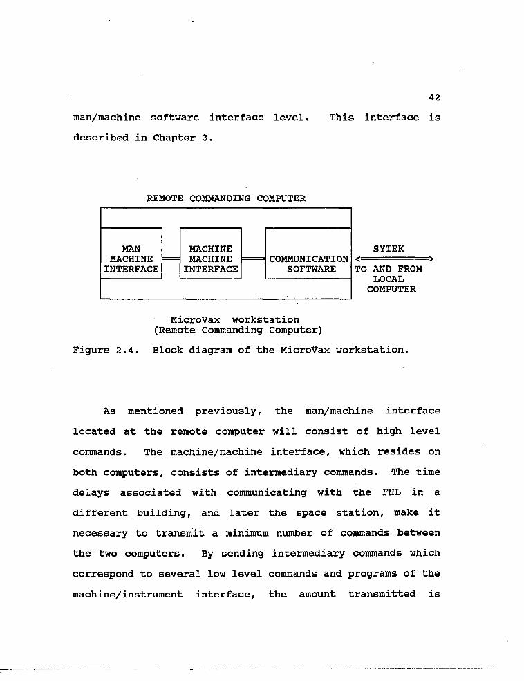
man/machine software interface level,
described in Chapter 3.
42
This interface is
REMOTE COMMANDING COMPUTER
SYTEK < > TO AND FROM
LOCAL COMPUTER
MicroVax workstation (Remote Commanding Computer)
Figure 2.4. Block diagram of the MicroVax workstation.
As mentioned previously, the man/machine interface
located at the remote computer will consist of high level
commands. The machine/machine interface, which resides on
both computers, consists of intermediary commands. The time
delays associated with communicating with the FHL in a
different building, and later the space station, make it
necessary to transmit a minimum number of commands between
the two computers. By sending intermediary commands which
correspond to several low level commands and programs of the
machine/instrument interface, the amount transmitted is
MAN MACHINE
INTERFACE
MACHINE MACHINE
INTERFACE COMMUNICATION
SOFTWARE
MAN MACHINE
INTERFACE
MACHINE MACHINE
INTERFACE COMMUNICATION
SOFTWARE

43
minimized, and so are the time delays.
2.3 THEORY AND PROTOCOL OF EXPERIMENTS
2.3.1 PH EXPERIMENT
The pH experiment consists of the robot removing a
specified syringe from its respective holder, filling up the
syringe with the desired fluid, placing the syringe into the
receptacle located at the inlet port of the pH meter, and
injecting the contents of the syringe into the capillary.
The capillary is narrow enough that the injected solution
will completely displace the fluid present in the capillary
without the two solutions being mixed. This displacement is
a function of the surface tension between the liquids and
the glass, and therefore is not affected by the microgravity
environment of space.
Before the pH of the sample solution can be reliably
measured, the pH meter must be calibrated using two test
solutions of known pH. The test solutions will be injected
into the pH electrode by the robot as described above. One
of the test solutions will have a low pH, while the other
solution will have a high pH. It has not yet been deter
mined how the meter will be calibrated in the FHL. Calibra
tion involves rotating certain knobs on the instrument until
the output matches the expected value for the known test
solution. It should be possible to adjust these knobs

44
electronically using the computer's multifunction board.
For the instruments which will eventually be installed
in the FHL aboard Space Station, the following general
concept is proposed. Instruments which are permanently
installed in the FHL of Space Station are integrated into
the electric supply of Space Station, and into the Space
Station Information System (SSIS). Since they can communi
cate with the RCC through a RS-232 port, it would be
wasteful to request the robot to flip a switch or rotate a
knob on these instruments. On the other hand, instruments
which are mission specific, and therefore not permanently
aboard Space Station, cannot be integrated into SSIS, since
their integration may cause damage to the system. For such
instruments, all functions must be accessible through the
front panel and must be operatable by the robot.
After the pH of a sample solution has been determined,
the pH meter must be flushed with a rinse solution, prefera
bly distilled water. As with the two calibrating solutions
and the sample solution, the robot will have to pick up a
syringe, fill it with the rinse solution, and inject the
solution into the inlet port of the pH meter. The rinse
solution will displace the sample solution remaining in the
capillary. All of the liquid displaced from the capillary
will be collected in a waste bag attached to the outlet
port.
45
The waste bag will be attached to the outlet port via a
rotating locking joint, similar to the lock designed into
the syringe adapter. The robot will remove the self sealing
waste bag and deposit it into a large container, which will
be emptied during Space Shuttle missions.
2.3.2. ELECTROPHORESIS EXPERIMENT
Electrophoresis is the process of separating solutions
into their charged components. These components can be
metal ions, organic acids, amino acids, peptides, and
proteins.
Isotachophoresis (ITP) is a type of electrophoresis in
which an electric dc current is applied over the length of a
narrow channel containing the solution to be separated. The
ITP experiment to be conducted in the simulated FHL will use
the apparatus described in detail in reference 16, and a
simplified block diagram of the apparatus is illustrated in
Figure 2.5, on the following page.
In the figure, (1) designates the narrow channel
containing the leading, sample, and terminating solutions.
The o's designate the injection ports for each of the
solutions. The leading and terminating electrolyte inlet
ports are close to their respective reservoirs. The sample
inlet port is between the other two ports. The x designates
the overflow valve through which excess solution in the

46
channel flows to the waste reservoir. (2) designates the
vessels for the leading and terminating electrolytes which
contain the electrodes for the high voltage, constant
current, power supply. The solutions in these vessels do
not enter the channel, but are vital to the electrochemical
reactions involved in ITP. (3) designates the measurement
electrodes which are used to measure the voltage gradient of
each zone. In steady state, the zones move through the
channel at a constant velocity, and each zone has a constant
voltage.
High Voltage Electrode
I (POS)
High Voltage Electrode (GND)
( 2 ) ( 2 )
Waste
| Leading Electrolyte Vessel
Terminating Electrolyte Vessel
Isotachophoretic Apparatus (Steady State)
(1) =o o=x=o:
I zone 11 zone 2I zone 3I
measurement electrodes ( 3 )
Figure 2.5. Block diagram of isotachophoretic apparatus.
When the dc current is applied, the charged components
of the solution separate according to their mobilities into
47
different zones. When the system reaches a steady state,
each zone moves with a constant velocity and has a length
proportional to the amount of sample constituent it con
tains. Every zone will exhibit discrete differences in such
physical properties as conductivity, pH value, temperature,
absorbance, etc. The zones are also characterized by having
a distinct constant voltage gradient, and it is this
property that is measured in ITP. The name isotachophoresis
comes from the fact that the individual zones move with a
constant velocity.
To identify or isolate the components of a sample
solution using ITP, two reference solutions which will
separate on either side of the sample solution must be used.
These solutions are called the leading and terminating
electrolytes. When the system reaches steady state, the
separated zones will exhibit distinct constant voltages in a
staircase fashion beginning with the leading electrolyte and
ending with the terminating electrolyte. The number of
steps between the first and the last voltage levels will
correspond to the number of different components in the
sample solution15. A response curve for a sample solution
consisting of one component is shown in Figure 2.6, on the
following page. In the figure, the voltage gradient of the
leading electrolyte is designated by (1), (2) is the voltage
gradient of the sample solution, and (3) is the voltage

48
gradient of the terminating electrolyte. ts is the transi
tion time and corresponds to the zone length of the com
ponent .
(V) ( 3 )
( 2 )
(1)
time
Figure 2.6. Response curve of an ITP experiment.
The protocol of the experiment is to first inject the
leading and terminating electrolytes into the channel
through their respective inlet ports. The leading electro
lyte is injected into the channel before the terminating
electrolyte. For each electrolyte, enough should be
injected to fill the channel and the excess will exit
through an overflow valve into the waste reservoir. It is
important that no air bubbles are allowed into the channel.
The presence of bubbles will be detected by a camera
positioned above the channel of the ITP apparatus. If
49
bubbles are detected, the leading and terminating solutions
will need to be reinjected into the channel until no bubbles
remain. This will be an iterative process using the robot.
The user at the remote commanding computer, and the camera,
will be involved in the feedback loop which detects the
presence, or absence, of bubbles.
After it is confirmed that no bubbles exist in the
channel, the voltage gradients for the leading and terminat
ing electrolytes will need to be measured. A high voltage,
constant current power supply, with its electrodes located
in the leading and terminating electrolyte vessels, is
switched on electronically. The separation of the electro
lytes will begin, and the resulting electric field is
measured at a predetermined location along the ITP channel
using the electronics described earlier. The signal is
measured until the transition between the leading and
terminating response curves is detected. The values
measured for the leading and terminating voltage gradients
will need to be stored in the computer's memory. The power
supply will temporarily be switched off, and a small amount
of the sample solution will be injected into the sample
inlet port. The power supply will then be switched on again
and the output of the system will be measured by the
computer using the A/D converter and the same sampling rate
of once per second. The computer will continue sampling

50
until the value corresponding to the terminating electrolyte
is detected.
Finally, the computer will compare the measured values
to the values previously stored, and determine the voltage
level of the sample solution and also the transition time.
The transition time is the time between the end of the
leading electrolyte voltage gradient and the beginning of
the terminating electrolyte voltage gradient and is related
to the zone length of the component17.
The sampled data will be returned in near real-time to
the user at the remote site, and will be displayed ill
graphical form on the remote monitor. Since the baud rate
is 9.6kBd per second, there will not be any problem trans
mitting the data.
It has not yet been determined how the images of the
FHL will ultimately be returned to the TV monitor. For the
model FHL at the UofA, the images are transferred over the
SYTEK network. A similar capability, operating in real
time, will be required for Space Station.

51
CHAPTER 3
MAN/MACHINE INTERFACE
The man/machine interface resides on the remote
commanding computer (RCC) and allows the user to operate the
fluid handling laboratory (FHL) from a remote site in a
convenient manner. It is important that the remote user
interface allows the scientist to operate the instruments
and conduct the experiments in a manner similar to the
methods used in his own laboratory. The software must not
require the user to be familiar with computers and should be
menu driven. It requires the user to input a minimum amount
of data, but it also allows him to keep a complete record of
his observations. The considerations which have gone into
the design of this interface are described in the following
paragraphs.
The user need not have an extensive background in
computers. Therefore, it is imperative that the software be
easy to use, and requires no extensive programming skills.
The program needs to be fast and efficient so that the
user can operate the FHL in near-real time. This allows the
user to observe data soon after it has been collected, or to
make alterations and corrections to the experiments while
they are being conducted.
The interface must also be flexible and versatile
52
enough to allow the user to take full advantage of the
laboratory's capabilities. The user obviously needs to be
able to conduct experiments, observe and manipulate the
collected data, and keep a log of his observations. He
also must have control access to the robot, the cameras, and
the multifunction board.
The interface should be designed as a generic program
which is independent of the type of equipment used in the
FHL. This will allow for changes in the equipment without
drastically effecting the software.
Finally, the man/machine interface must provide the
option for the more experienced user to make improvements
and corrections in experiments being conducted in the FHL.
The user may need to be able to make changes in the programs
which manipulate the robot and control the multifunction
board, or he may need to write completely new programs.
This option should be accessible for the experienced user,
but at the same time, it should be impossible for the novice
to cause permanent damage accidentally. Therefore, evoking
this option will result in a series of cautions and warnings
before it is completely activated. A password and a
verification will be required before any new programs or
changes may be saved.
The man/machine interface also provides for immediate
access by the staff of the FHL aboard Space Station. The

53
staff will need this ability in case something goes wrong
with the operation of the FHL, and they need to seize imme
diate control of the LCC. A special password will be issued
to a few select members of the staff, and possibly to people
at NASA. When this password is entered, the user who is
operating the system will temporarily lose control of the
FHL. He will be informed that the staff or NASA has
intervened, and that control will be returned to him as soon
as possible. The special password will override all other
passwords and will allow the staff member to use all the
commands of the three interfaces. The user in space will
not be able to use the same type of mouse as the user on
Earth, but a similar device will need to be available so
that he may use the menus of the man/machine interface.
The interface described in this chapter resides on a
MicroVax running OASIS software. OASIS is an acronym for
the Operations and Science Instrument Support teleoperations
software package, which was developed for NASA by the
Operations and Information Systems Division of the Labor
atory for Atmospheric and Space Physics (LASP) at the
University of Colorado at Boulder. OASIS is coded in Ada,
and it was designed for the teleoperation of instruments and
remote acquisition of data. It allows the design of menus
in a user interface, and it receives incoming telemetry
data.

54
The interface consists of a series of hierarchical
menus. When the user selects an item from the MAIN menu, a
submenu related to that item will replace the MAIN menu on
the screen. The user may select the menu items using a
mouse. The depth of the menu levels depends on the parti
cular item. The available items, and their corresponding
submenus, will be described in detail in this chapter.
Although the intent of this chapter is to describe the
man/machine interface necessary for the FHL at the UofA, it
will include many features which may not be required or be
feasible at this stage. The chapter will actually describe
the interface as it should be in the ideal case. This does
not mean that the interface cannot be implemented with the
equipment presently available, but it does mean that some of
the features described may not be available, or needed, when
the interface is initially used. However, all features, and
probably additional ones, will become useful when the FHL is
installed aboard Space Station.
3.1 START-PP PROCEDURE
The user must establish a connection to the FHL
laboratory before he can begin operating any of the avail
able instruments or experiments. The first menu the user
sees will consist of a CONNECT and a DISCONNECT button. The
CONNECT button will begin a session, while the DISCONNECT

55
button will terminate a session.
After the CONNECT button has been activated, the user
will be given the choice of accessing the man/machine
interface for either the FHL or the atmospheric telescope
facility (ATF) projects. The two interfaces are sister
programs and will be similar since some menu items, such as
a logbook and an editor, will be common to both projects.
The details of the man/machine interface for the ATF project
are discussed in a separate paper4.
The block diagram in figure 3.1 illustrates the path of
the first two menus. As mentioned before, each new menu
replaces the previous menu on the screen when the user
selects an item. The menu items are activated by clicking a
button on the mouse.
CONNECT DISCONNECT
FHL ATF QUIT
Figure 3.1. Block diagram of first two menus.
When the user selects either FHL or ATF, the communica
tion link between the RCC and the requested LCC is estab-

56
lished. Assuming the user selects FHL, he will be presented
with any news items concerning the FHL which have been
reported since his last session. These news items will
inform the user of a change in the status of the equipment
in the FHL. Eventually, these messages may be sent by
astronauts working in the FHL aboard Space Station.
In the future, it is very possible that there will
exist many remote sites which can access the FHL aboard
Space Station. However, only one user at a time will be
able to operate the instruments in the laboratory. All the
other users who connect to the system will have to be
satisfied observing the events which take place in the FHL.
They will be able to use the passive commands which affect
their display, but they will not be able to operate any of
the instruments. The user who has access to the instruments
will be designated as the experiment commander (EC). All
other users will be known as an experiment observers (EO's).
The first user to connect to the system will become the
EC. This will give him the "privilege" of operating the
FHL. This "privilege" may be thought of as a key to the FHL
which can only be used by one person at a time. Users who
later connect to the system will be informed that a parti
cular user has the privilege. They will also be informed of
their potential position in the queue, and asked if they
want to be placed in the system's queue. Assuming they

57
respond positively, they will have the option of remaining
logged into the system, or they may terminate the connection
and the LCC will contact them when it becomes their turn to
operate the system. When the first user has .finished using
the FHL, the user who is at the top of the queue will be
given the privilege of operating the laboratory.
The privilege of operating the FHL may also be trans
ferred from one user to another. This may become necessary
if the EC has problems with some of the equipment, or cannot
satisfactorily conduct an experiment. He may then tempo
rarily transfer the key, or privilege, to a user who is an
expert in the particular problem area. The ability to
transfer the privilege will be a function of the UTILITY
submenu of the MAIN menu. This submenu will be described in
detail in a later section.
After the user reads the news items, and is informed of
his position in the queue, the MAIN menu of the man/machine
interface will appear on the screen. This menu will include
a NEWS button which will allow the user to input comments
related to the news items. This submenu will also allow the
user to read the news items again.
The MAIN menu will be described in the next section,
while the submenus, such as NEWS and UTILITY, will be
described in detail in later sections.

58
3.2 MATH MENU
The man/machine interface will consist of hierarchical
menus which may be activated in numerous ways and give the
user a fast, versatile, and easy way to operate the FHL.
The MAIN menu will be displayed horizontally along the
bottom of the screen, and will consist of ten items. Each
item will have at least one submenu, and may have as many as
four. The MAIN menu is illustrated in figure 3.2.
EXPER ROBOT CAMERA MULTI PROGRAM NEWS LOG UTIL HELP EXIT BOARD
Figure 3.2. MAIN menu of man/machine.
The items shown in figure 3.2 were selected because
they allow the user to take full advantage of the FHL's many
capabilities. A user may simply run an experiment "cook
book" style, or he may choose to change the configurations
of various equipment (such as the robot or the cameras) to
suit his needs. The user may also use the editor of the
UTILITY submenu to create a notebook for his observations.
If he needs to know more about a particular menu item, a
detailed help file will always be available. The following

59
is a list of the MAIN menu items and their related functions
(a detailed description of each of the submenus may be found
in their respective sections):
1. EXPER - (Experiment) - This item activates a submenu
which contains a list of the various experiments which may
be performed in the FHL. When the user selects an experi
ment, he may be required to enter some data, such as which
solution to use. The user might be able to perform experi
ments simultaneously, or in succession, depending on the
nature of the experiment. This submenu will also contain a
DATA button which allows the user to observe data from a
file, and/or data being currently collected on the screen in
various formats.
2. ROBOT - This submenu contains commands which allow the
user to interrupt the motion of the robot and change its
configuration. The user can also request the position of
the joint angles.
3. CAMERAS - Allows the user to choose between cameras and
to select a split-screen on the television monitor. Also
allows the user to change the camera's viewing angle and set
the focus of the camera. It is possible that other similar
control features may be required in future applications.
4. MULTIBOARD - (MULTIFUNCTION BOARD) - Allows the user to
use the various features of the multifunction board located
in the LCC.

60
5. PROGRAM - (PROGRAMMING) - Intended for use by the more
advanced user, this submenu allows the user to program the
robot and the multifunction board. The commands of the
machine/machine interface are also accessed through this
menu. Anyone may use this submenu, but a password is
required before any changes or programs may be saved.
6. NEWS - This submenu allows the user to read any NEWS
items which were displayed at the beginning of the session.
For the most part, these news items will be from the staff
of the FHL and may inform the user of broken equipment or
new experiments. The user will also have the opportunity to
send information concerning the equipment and experiments to
the staff, and this information will become part of the NEWS
bulletin available to all users until the staff of the FHL
clears it.
7. LOG - A logbook will be maintained which will keep
track of all the events of the session and when they occur.
It will be started automatically at the beginning of the
session. The LOG submenu gives access to the logbook, and
allows the user to manually enter or edit pieces of informa
tion. The user will not be permitted to edit some portions
of the logbook, such as when events occur, so that the
logbook may be later used for fault analysis. For example,
if a piece of equipment is broken, it may be possible, by
analyzing the logbook, to find out what caused the malfunc

61
tion. The logbook may also be printed in hardcopy form, so
the user has a permanent copy of the events which took place
during the session.
8. UTILITIES - This submenu allows the user to access the
operating system of the RCC. The user may then engage the
mail system, the editor, or perform any of the functions
available with VMS, if the RCC is a DECnet system. The
submenu also allows the user to send messages to other users
at remote sites through the local controlling computer in
the fluid handling laboratory. The privilege of being the
active user is also transferred through this menu.
9. HELP - OASIS includes a help facility in which the help
command is a part of every menu. After the user activates
it, he may obtain help on the various topics of a menu by
selecting the desired item. The format of the help will
depend on the menu item. If the user selects HELP from the
MAIN menu, and then chooses an item, a brief description of
the item's corresponding submenus, and what they can do,
will be displayed. For some items, such as CAMERAS or
ROBOT, the description will also tell the user general facts
about the item. This may include the number and type of
cameras, or the brand of the robot. In cases where the
description is too bulky to fit entirely on one screen, the
system will prompt the user for a carriage return after each
screen is displayed.

62
The HELP facility will also include a HELP submenu
which can be accessed on any menu by selecting HELP twice.
This HELP submenu will include a WHERE feature, as well as a
SEARCH feature. The HELP submenu is described in more
detail in section 3.3.9.
10. EXIT - Terminates the communication link between the
RCC and the LCC and returns the user to the FHL/ATF menu.
When an item is selected, the MAIN menu is cleared from
the screen, and a detailed submenu will appear in its place.
The commands in the submenu will be related to the item
selected, and may be activated using the mouse. Activating
some of these commands will result in a request for more
information such as values, while others will display a
lower level submenu!
The activation of items which require lower level menus
will result in the present menu being cleared, and the new
menu appearing in its place. More than one menu may not be
active at any time, and therefore the user must leave a menu
before he can begin working in a different menu. Submenus
directly below the MAIN menu will have only "MAIN MENU"
listed as an item, while menus which are more than one level
below the MAIN menu will have "LAST MENU" and "MAIN MENU"
listed as items. This will allow the user to switch as
conveniently as possible between menus.
The menus will- be located on the bottom of the screen.

63
The screen portion above the menu bar will be reserved for
workspace, and will typically be used as an editing screen
when the user requests a notebook or wants to program in
Basic. It may also be used to display tables the user
requests, such as joint angles of the robot, or graphs of
the data collected from an experiment.
The next section describes the submenus of the man/ma
chine interface.
3.3 SUBMENUS OF THE MAN/MACHINE INTERFACE
3.3.1. EXPERIMENT
This submenu is to be used exclusively for the experi
ments which have been designed for the FHL. Presently,
these experiments include measuring the pH of a solution and
separating a solution into its charged components using
isotachophoresis. Both of these experiments have been
discussed in detail in "Machine to Machine Interface for
Teleoperation of a Fluid Handling Laboratory"5, and also in
Chapter 2 of this thesis. As other experiments become
available in the FHL, they can easily be added to this
submenu.
These experiments have been designed for the FHL in the
sense that all the movements of the robot and functions of
the multifunction board and the LCC which are required to
conduct the experiments have been stored as prewritten

64
programs. The experiments are automated and require a
minimal amount of user attention. The user simply chooses
the experiment he wants performed, chooses the solutions to
be analyzed, and monitors the experiment on the TV screen to
ensure the proper execution of all the activities. He may
also observe the data being collected by using the DATA
subsubmenu.
If the user wants to change the format of the experi
ments, or use the robot or the multifunction board for other
purposes, he will have to use one or more of the other
submenus.
Figure 3.3 illustrates the EXPERIMENT submenu after it
has been activated, as described in the previous section.
pH ISOTACHO INTER CONT DATA HELP MAIN pH MENU
Figure 3.3 EXPERIMENT submenu.
The EXPERIMENT submenu will also be used to correct
errors which may occur in the execution of experiments. For
example, the robot may be slightly off in its movements and
therefore not be able to insert the syringe needle into the
desired location accurately. The user will observe this

65
problem on the TV screen and will need to interrupt the
program. This interrupt (INTER) command, as well as a
continue (COMT) command, will be part of the EXPERIMENT
submenu. The INTER command will have priority over other
commands, and will not be pushed into the command buffer.
Instead, the LCC will immediately suspend all actions when
this command is received. The CONT command is also a
priority command, and a password will be required to
activate it. This will prevent an unauthorized user from
damaging equipment by continuing an interrupted procedure
before the problem has been solved.
For example, assume the user is conducting a pH
experiment and he notices that the robot is off course and
is about to crash. He will select the INTER command to stop
the "experiment. A window will be displayed on the screen,
listing the lines of code which make up the program in the
area where the error occurred. For example, the window
might list the ten lines of code which were executed before
the INTER command was issued, as well as the next ten lines
of code. The lines which had been executed will be desig
nated by reverse video. An experienced user can then
determine where the error occurred, or at least, what lines
should be reexecuted or possibly skipped. If the error
involved the positioning of the robot, he will use the items
described in the next section to reposition the robot. He

66
will then highlight the line of code from which he would
like to continue the experiment, and select the CONT
command. The user will have to enter a password before the
experiment will continue. If the user was inexperienced,
and did not know how to analyze the program or operate the
robot, he should transfer control of the FHL to another user
using the PRIVILEGE command of the UTILITY submenu described
in a later section. Directly manipulating the robot, or a
program, as described above, will require a password.
When the user selects an experiment, he will also need
to choose which solution should be analyzed, as well as a
name for the file which will contain the collected data.
The different solutions are stored in their respective
storage vessels. A lower level menu containing the avail
able vessels, and the solutions they contain, will be dis
played and the user will need to pick the desired vessel.
If the user activates "pH", a subsubmenu corresponding
to that experiment will replace the submenu on the screen.
The pH subsubmenu is illustrated in figure 3.4.
SAMPLE FILE RUN HELP LAST MAIN SOLUTION NAME MENU MENU
Figure 3.4. pH subsubmenu.

67
When the user activates "SAMPLE SOLUTION", a lower
submenu listing the possible solutions for the pH experiment
will be displayed. The user will select the sample solution
by picking the desired solution from the pH solution
submenu. If the user attempts to run the experiment without
selecting a solution, a hazard window with an error message
will be displayed. The user may enter a name for a file in
which the collected data will be stored by selecting
"FILENAME". If the user elects not to enter a filename, a
default name will be provided including the type of experi
ment, pH, and the date. The default extension will be DAT.
The experiment will be started when the user selects "RUN".
The isotachophoresis experiment will involve leading,
terminating, and sample solutions. Therefore, the display
for this experiment will be similar to that shown in figure
3.4, but the user will need to enter the leading and
terminating solutions, as well as the sample solution.
Again, lower submenus will be displayed listing the possible
solutions for the leading, terminating, and sample solu
tions, and the user will have to choose each solution. If
the user attempts to run the experiment before the required
solutions have been chosen, a haziard window with an error
message will be displayed. The user may also enter a
filename, although if he does not, a default name will be

68
supplied which will include the type of experiment, ITP, the
date, and have the extension DAT. The experiment will begin
when the user selects "RUN". The subsubmenu for an isotach-
ophoresis experiment is shown in figure 3.5.
SAMPLE LEADING TERMINATING FILE RUN HELP LAST MAIN SOLUTION SOLUTION SOLUTION NAME MENU MENU
-Figure 3.5. ISOTACHOPHORESIS subsubmenu.
Activating DATA on the EXPERIMENT submenu will allow
the user to observe the data collected during an experiment
in a variety of ways. The data will be transferred to the
RCC from the LCC at a maximum rate of one sample per second.
This sampling rate has been chosen for the isotachophoresis
experiment because it will give accurate results without
dedicating too much computer time for data collection. The
pH experiment will require measuring several samples until a
steady-state value has been measured. Therefore, it does
not require a sampling rate faster than once per second. In
the future, the sampling rate may be increased as required
by new and different experiments. The DATA subsubmenu is
illustrated in figure 3.6.

69
FILE REAL X-Y TABLE # OF HELP LAST MAIN NAME TIME PLOT PLOTS MENU MENU
Figure 3.6. DATA subsubmenu.
The user will have the option of viewing the data on an
X-Y plot or in tabular form. The X-Y plot will be the most
useful for the isotachophoresis data since it will consist
of a stepwise voltage change over time. The voltage
amplitude will be plotted along the ordinate, while time
will be plotted along the abscissa. The time, taken from
the LCC's clock, at which each data point was sampled will
also be displayed above the graph, and this will correspond
to the "age" of the data point. The data from a pH measure
ment may also be plotted on the X-Y plot with the pH level
along the ordinate, and time along the abscissa. The limits
on the axes will be set by the user. Tabular format will
simply list the data in columns, and will be a useful way to
store the data for later postprocessing. The clock time
when the data was sampled will also be displayed in a
column.
The user may either view the data while it is being
collected, or after it has been collected. The data will be
stored on the RCC, using either the filename entered by the

70
user, or the default filename. By selecting "# OF PLOTS",
the user will be able to compare data from more than one
experiment. When this item is selected, the user will be
prompted for a number. The screen will be split into the
requested number of sections, and the user will be permitted
to view data from earlier experiments, as well as a current
experiment, in either graphical or tabular form. For
example, he may want to look at a table comparing the pH of
the two calibrating solutions and the sample solution. He
will need to enter 3, for number of plots, and the filenames
corresponding to each solution.
The user will first have to select whether he wants to
observe data which is being collected in near real-time or
imported from a file. If the user selects FILENAME, he will
be prompted to enter a filename. The list of available
files will be displayed.
The REALTIME option will only be available if an
experiment is being performed. The data will be displayed
on the screen in the desired format and will be stored into
a file simultaneously. The data file will be given the
filename the user entered previously, using either the pH or
the ITP submenu. If the user did not enter a filename, a
default name will be used, including the type of experiment
(pH or ITP), and the date. In either case, the filename
will have the extension DAT.

71
Next, the user- will need to choose the format in which
the data is displayed. As described earlier, his options
include an X-Y plot and tabular form. The data from the
plots or the table will be obtained from the file, he has
previously selected, or as it is collected if he selected
REALTIME.
The user will be permitted to display more than one
plot or table on the screen simultaneously. If he wants to
observe data from several files on one graph, he must first
select the number of plots, then the files, and finally, the
graph format. Similarly, if he wants to observe data from
one file on a graph and in a table simultaneously, he must
first select the number of plots (2) , then the file (or
REALTIME), and finally, the two formats.
Finally, the user may obtain help on any of the items
of the EXPERIMENT submenu by activating HELP. If after
activating HELP, he selects either pH or ISOTACHO, a brief
description of the experiment and its theory will be
displayed on the screen.
The HELP description for the two experiments conducted
in the FHL will include a procedural checklist. It will
list the steps involved with an experiment, including the
selection of the proper menu items. As the steps of the
experiment are completed, they will be marked with a check
or cross. The checklist will be very useful if the user
72
needs to interrupt the experiment. It will inform the user
of what steps of the experiment have been completed, and
what steps have not yet been completed. If necessary, the
user may stop the experiment using the priority INTERRUPT
command of the EXPERIMENT submenu, use the checklist to
determine the current step of an experiment, repeat an
earlier step, and finally, continue the automated experiment
from where it was interrupted.
If the user selects INTER or CONT from the experiment
submenu after activating HELP, a brief description of the
command and its function will be displayed.
Selecting DATA after activating HELP will result in a
brief description of the method with which the data is
collected.
When the HELP command on the other submenus (figures
3.4, 3.5, and 3.6) is activated., the user will be able to
receive an explanation of any of the menu items by selecting
that item. In some cases, the explanation will include an
example.
3.3.2. ROBOT
This submenu gives the user access to all of the
robot's movements and joint positions. It is primarily used
to correct errors in the robot's movements, and requires a
password. The user can interrupt an experiment, using the

73
EXPERIMENT submenu, and then use this submenu to move the
robot to its correct position.
The user can watch the robot's motions on the TV
screen, and therefore may need to manipulate the cameras in
order to obtain a good view. The manipulation of cameras
will be discussed in the next section.
Some experienced users may wish to program the robot
for new tasks, using a teach pendant. This option will be
available, for users who have the correct password, through
the PROGRAM submenu. This submenu will also be discussed in
a later section.
Figure 3.7 shows the ROBOT submenu which replaces the
MAIN menu on the screen when activated.
STOP CONT HOME TORSO ARM ELBOW PITCH ROLL GRIP SHOW DISP HELP MAIN MENU
Figure 3.7. ROBOT submenu.
The STOP command in the submenu is a priority command
which is used to stop the robot's motion. It is not used to
interrupt an experiment. The CONT command is used after the
STOP command to resume the robot's motion. The two commands

74
are normally activated by a user who is manipulating the
robot and needs to stop its movement before it crashes into
something, the HOME command is also a priority command, and
it returns the robot's arm to its home position. None of
these commands require any additional input from the user.
Activating any of the joint commands, such as ARM, or
ROLL, will result in the display of speed, movement, and
increment angle blocks. Sample blocks are shown in figure
3.8, where (a) is the speed increment block, (b) illustrates
the movement blocks for the arm and wrist joints, and (c) is
the increment angle indicator block.
SLOW FAST
I M I
SPEED INDICATOR
/ \ FAST
\ / SLOW
(a)
II
INCREMENT ANGLE INDICATOR
ARM / \
\ /
/
\
\ HIGHER
/ LOWER
(c)
( b )
ROLL
< >
Figure 3.8. Robot joint movement blocks.

75
The speed block and speed indicator will be the same
for every joint. The user will be able to increase or
decrease the speed of movement by highlighting the respec
tive arrow and clicking the mouse button. The selected
speed will take effect when the user moves a joint. The
relative speed of motion will be represented by the tick
marks in the speed indicator. The present speed will be
designated by the highlighted tick. The tick at the left is
slowest, at the right, fastest.
The user will activate the appropriate arrows in the
movement block to move a joint up, down, left, or right,
depending on the joint's configuration. Changing the arm,
elbow, and pitch positions require the up and down arrows,
while the torso, roll, and grip positions require the left
and right arrows.
The angle block and angle increment indicator will also
be the same for every joint. The user may increase or
decrease the angle with which the robot moves by selecting
the higher or lower arrows, respectively. The relative
angle increment will be indicated by the tick marks in the
increment indicator block. The largest increment will be on
the right, while the smallest increment will be on the left.
The SHOW command is used when the user wishes to know
the position values of all the joints. A table, similar to
table 1, is displayed and lists all the joint positions and

76
their values. The table will consist of the names of the
joints with their respective values listed below them. When
the user activates SHOW, all of the values will be listed.
TABLE 1 JOINT ANGLES AND VALUES
TORSO ARM ELBOW PITCH ROLL GRIP DEGREES DEGREES DEGREES DEGREES DEGREES VALUE
The user may also select the DISPLAY (DISP) command
from the ROBOT submenu. This command is very similar to the
SHOW command, except that the values of the table are
automatically updated once per second, rather than simply
displayed once.
When the user selects the HELP command on the ROBOT
submenu, he can thereafter select any item he needs to learn
more about, and a brief explanation will be displayed in a
Help window. For example, if the user wants to learn how to
manipulate a particular joint, such as the arm, he needs to
activate that item, after first selecting HELP. The speed,
movement, and angle blocks will be displayed together with
an explanation of how the joint is manipulated. This is
illustrated in figure 3.9, in which (a) illustrates the

SLOW FAST
II
SPEED INDICATOR
/ \ FAST
\ / SLOW
ARM / \
\ /
SPEED BLOCK MOVEMENT
BLOCK
l l l l l l l l
INCREMENT INDICATOR
/
\
\ HIGHER
/ LOWER
RETURN
RETURN BLOCK
(LEAVE HELP)
ANGLE BLOCK
77
Figure 3.9. HELP display for robot joints. (a)
The arrows in the speed block are used to alter
the speed of the robot's motions during program
execution. The tick marks in the speed indicator
block indicate the robot's relative speed.
The movement block allows the user to increase or
decrease the value of the joint angle. The user should
watch the TV monitor to observe the effects of moving
the joint.
The arrows in the angle block are used to alter
the angular increment/decrement of the robot during
programming. The tick marks in the incremental
indicator block indicate the relative angle setting.
For more detailed information, consult the manual.
(b)

78
speed indicator and movement blocks, and (b) is an explana
tion of the two blocks, and how they are used. The RETURN
button in (a) is used to return the user to the ROBOT
submenu.
When the user selects either STOP or CONT after
activating the HELP item, a brief description of the
respective function will be displayed.
3.3.3 CAMERAS
This submenu will be somewhat dependent on the number
and types of cameras available in the FHL. It has not yet
been decided how many cameras will be used, or where they
will be located. The user will be able to observe the
activities of the laboratory on the television monitor, and
will use this submenu to manipulate the picture he sees.
The submenu is shown in figure 3.10, and it will allow
the user to turn cameras on and off, pick between a number
of different cameras, zoom, pan, or tilt a camera, and set
up split screens on the TV monitor.
ON # OFF # VIEW # PAN # TILT # LENS # ZOOM # HELP MAIN MENU
Figure 3.10. CAMERA submenu.

79
A table will be displayed on the screen when the
submenu is first activated. This table will list the
various cameras, their capabilities, and their respective
numbers. For example, camera 1 may be set up to show the
entire FHL, and could be used to view the configuration of
the robot. It will have a wide angle lens and a small range
of rotation. Camera 2 may be focused on the inlet ports of
the various instruments and therefore will have a telephoto
and a normal lens, as well as a small angle of rotation. A
third camera may be located on the end effector of the robot
and will have the telephoto and normal lens and a wide angle
of rotation. This camera would also have to be quite small,
so that it does need exceed the load limitations of the
robot. As mentioned before, the position and number of the
cameras have not yet been determined and the example which
has been described is completely hypothetical.
Activating the ON or OFF commands of the submenu will
result only in a request for the camera number. The user
can enter any combination of cameras, including ALL. To
enter a series of cameras, the numbers need to be separated
by commas, and the list terminated by pressing the enter
key.
The VIEW command will be used to choose which images
will appear on the TV monitor. The user will be requested
to enter the camera number or numbers. If more than one

80
camera is chosen, the TV screen will automatically be split
into as many portions as required to view the chosen images.
For example, if the user selects two cameras, the screen
will be split in half.
When the PAN, TILT, and ZOOM commands are activated,
the user will be prompted for the camera number. The
default number will correspond to the last camera activated,
and the user will simply need to press the enter key to
manipulate the same camera. If he wants to manipulate a
different camera, he will need to enter a new number. After
the number is entered, a movement block will be displayed on
the screen. The blocks for each of the commands are shown
in figure 3.11, where (a) is the speed block, (b) is the
increment angle block, and (c) , (d) , and (e) are the pan,
tilt, and zoom movement blocks.
/ \ FAST
\ / SLOW
/ \ HIGHER
\ / LOWER
TILT ZOOM / \ / \
\ / \ /
(a) (b) (c)
Figure 3.11. Camera movement blocks.
(d) (e)
The user will adjust the camera's position or image by
81
activating the arrows in these blocks. As with the robot in
the previous section, the user may vary the speed of
movement by activating the arrows in the speed block. The
speed indicator, although not shown in figure 3.11, will
also be displayed on the screen, and will operate in the
manner described in the previous section.
The user may also vary the increment angle with which
the cameras pan, tilt, or zoom. The increment angle
indicator block will also be displayed on the screen, and
will operate in the same manner it did for the robot.
The LENS # command will be used to switch between
telephoto and normal lenses on cameras that have this
option. The user will need to consult the camera table to
determine which cameras have two lenses. When the lens
command is activated, the user will be prompted for the
camera number. The command will behave as a toggle switch
in changing the lens. For example, if a camera is set up in
wide lens mode, the first time LENS # is activated, it will
switch to the telephoto lens. The next time LENS # is
activated, the camera will switch back to the wide lens.
If the user enters a camera number that only has one
lens, a hazard window will be displayed with an error
message.
The HELP command will behave in the same manner as it
does for the EXPERIMENT and ROBOT submenus. After it is

82
selected, the user may receive a brief description of any of
the items on the menu by activating the respective item.
The description, and possibly an example, will be displayed
on the screen. If the user needs more detailed information,
he should consult the manual.
3.3.4. MULTIFUNCTION BOARD
The MULTIBOARD submenu will be used to take advantage
of some of the preprogrammed capabilities of the multifunc
tion board. However, it will not permit the user to program
the multifunction board. Most multifunction boards have
analog-to-digital and digital-to-analog converters as well
as parallel input/output channels and timers. The board
used in the FHL at the UofA is a LabTender Multifunction
Board, and it has all of these capabilities.
By activating this submenu, the user will be able to
turn various instruments on and off, collect data, output
logic signals, and tise the multifunction board as a function
generator. Programs to perform all of these operations will
be stored on the LCC, and issuing commands from this submenu
will call and execute the corresponding programs. The user
will need to enter various parameters, depending on the
command activated, and these will be passed to the programs.
Many of these programs will be used in conducting the
experiments performed in the FHL, and this submenu will give
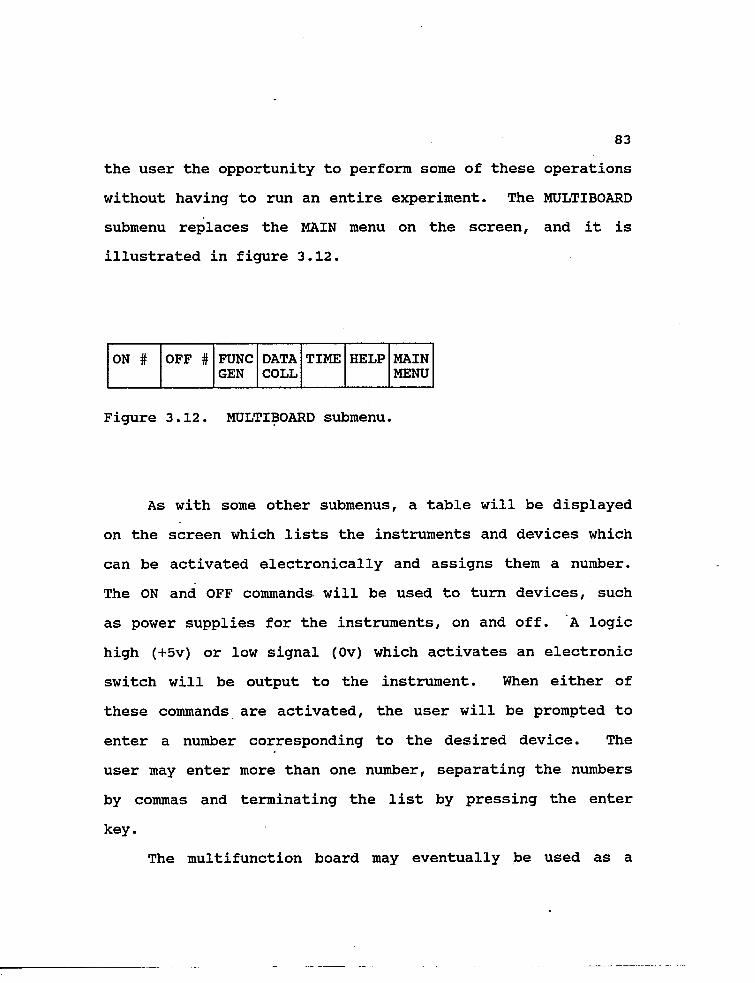
83
the user the opportunity to perform some of these operations
without having to run an entire experiment. The MULTIBOARD
submenu replaces the MAIN menu on the screen, and it is
illustrated in figure 3.12.
ON # OFF # FUNC DATA TIME HELP MAIN GEN COLL MENU
Figure 3.12. MULTIBOARD submenu.
As with some other submenus, a table will be displayed
on the screen which lists the instruments and devices which
can be activated electronically and assigns them a number.
The ON and OFF commands will be used to turn devices, such
as power supplies for the instruments, on and off. A logic
high (+5v) or low signal (Ov) which activates an electronic
switch will be output to the instrument. When either of
these commands are activated, the user will be prompted to
enter a number corresponding to the desired device. The
user may enter more than one number, separating the numbers
by commas and terminating the list by pressing the enter
key.
The multifunction board may eventually be used as a

84
function generator to output wave forms such as sine,
triangle, and square waves. This menu item is included in
the MULTIBOARD submenu, but it will not be implemented at
this time. The description of the FUNC GEN subsubmenu is
included in Appendix E.
The user may also request that data be collected from a
particular instrument by activating the DATA COLL item of
the submenu. The A/D converters are used to collect data,
and when this item is selected, a table will appear on the
screen listing the various converters and the instruments
that are connected to them. A subsubmenu for data collec
tion will also appear on the screen, replacing the MULTI
FUNCTION board submenu. This new menu is shown in Figure
3.13.
A/D FREQ GAIN FILE START STOP TEST HELP LAST MAIN # NAME MENU MENU
Figure 3.13. DATA COLLECTION subsubmenu.
The first four items on the menu will prompt the user
for an input when activated. The user will first need to
choose which A/D channel to activate. He may then set the
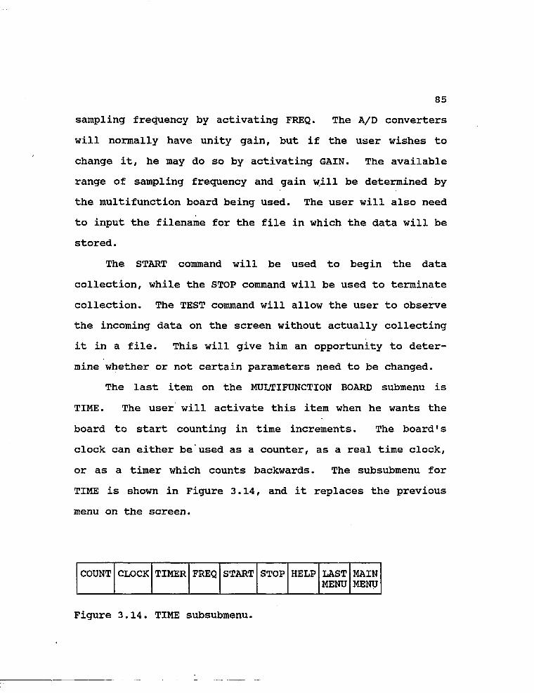
85
sampling frequency by activating FREQ. The A/D converters
will normally have unity gain, but if the user wishes to
change it, he may do so by activating GAIN. The available
range of sampling frequency and gain will be determined by
the multifunction board being used. The user will also need
to input the filename for the file in which the data will be
stored.
The START command will be used to begin the data
collection, while the STOP command will be used to terminate
collection. The TEST command will allow the user to observe
the incoming data on the screen without actually collecting
it in a file. This will give him an opportunity to deter
mine whether or not certain parameters need to be changed.
The last item on the MULTIFUNCTION BOARD submenu is
TIME. The user will activate this item when he wants the
board to start counting in time increments. The board's
clock can either be'used as a counter, as a real time clock,
or as a timer which counts backwards. The subsubmenu for
TIME is shown in Figure 3.14, and it replaces the previous
menu on the screen.
COUNT CLOCK TIMER FREQ START STOP HELP LAST MAIN MENU MENU
Figure 3.14. TIME subsubmenu.

86
After activating COUNT, the user will need to input the
counting frequency by selecting FREQ. The multifunction
board will begin counting from 0 in intervals corresponding
to the frequency input by the user, but only after the START
button has been selected. For example, when the user
selects FREQ, he will be prompted to input the counting
frequency. If he enters one, the counter will count once
per second. If he enters two, the counter will count once
every other second.. And, if he enters one-half (0.5), the
counter will count twice every second. The counter will
continue to count until the user selects STOP.
If the user activates CLOCK, he will be prompted for
the initial time and the board will increment its clock in
one second intervals, using military hours. The one second
intervals is a default value, and may be changed by select
ing FREQ. This will allow the user to use the clock as a
stopwatch, if he so desires. Again, the user must activate
the START button before the clock becomes active. The STOP
button is used to terminate both the counter and the clock.
The multifunction board may also be used as a timer,
counting backwards from a pre-set time, input by the user.
The default counting time will be once per second, but the
user may change this with the FREQ command. The timer is
started when the user activates START, and as it counts, a
timer window will be displayed on the screen. When it

87
reaches zero, the RCC will emit a beep, and a message will
be displayed.
Once again, the HELP command is available on each of
the menus. After activating HELP, a description of a menu
item will be displayed when the user selects the particular
item. In some cases, this description will include ex
amples .
If the user needs more information after reviewing the
on-line help, he should consult the manual for the man/ma
chine interface.
3.3.5. PROGRAM
This submenu will allow the user to program the robot
and the multifunction board, as well as access the machine/-
machine interface. Because programming these items could
have disastrous effects on the FHL, only users with pass
words may save any programs. Users who are given passwords
should be experienced in programming a robot using a teach
pendant, in programming multifunction boards, and in using a
language similar to the machine/machine interface. The
board currently used in the FHL is programmed in Basic.
When the PROGRAM item is selected from the MAIN menu,
the user will be given a choice between programming the
robot, the multifunction board, or using the machine/machine
interface. The menu which gives him this choice will

88
replace the MAIN menu on the screen, and is shown in Figure
3.15.
ROBOT MULTIFUNCTION MACH/MACH HELP MAIN BOARD INTERFACE MENU
Figure 3.15. PROGRAM submenu.
As mentioned before, the robot will be programmed via a
teach pendant. Activating the ROBOT command on the submenu
will cause the robot to enter the teach pendant mode, which
allows it to be programmed. The user will be required to
enter a password when he activates the item, and a second
password will be required before he may save any programs.
The user must store the program as a series of successive
stop points obtained by the robot. It is assumed that the
user is familiar with programming robots using teach
pendants. A table will be displayed listing the individual
joints and their values, and these values will be updated
once every five seconds. It will be imperative that the
user watches the robot on the TV screen, and a message
informing him of this will also be displayed.
A subsubmenu will be displayed, replacing the PROGRAM

89
submenu. This menu lists the joints of the arm, and when an
item is activated, a speed block and the corresponding
movement block will be displayed on the screen. In Figure
3.16, (a) illustrates the ROBOT PROGRAM submenu, (b) shows
the speed block and indicator, (c) is the incremental angle
indicator, (d) illustrates the proportional speed block and
indicator, and (e) shows the movement blocks for ARM and
ROLL, including a store button for indicating the final
position.
TORSO ARM ELBOW PITCH ROLL GRIP SAVE RUN HELP LAST MAIN MENU MENU
(a)
II
SPEED INDICATOR
LOW HIGH
II
PROPORTIONAL SPEED BLOCK
( d )
/ \ FAST
\ / SLOW
(b)
/ \ HIGH
\ / LOW
II
INCREMENT INDICATOR
STORE
\ HIGHER
/ LOWER
(C)
ROLL
Figure 3.16. ROBOT PROGRAMMING menus.
90
The user can change the speed of movement using the up
and down arrows in the speed block. The tick marks to the
right of the arrows indicate the robot's speed, where
fastest is at the top, and slowest is at the bottom. One of
the ticks will be highlighted to indicate the current speed.
The selected speed will take effect at execution time rather
than at programming time.
The incremental angle indicator allows, the user to
change the incremental angle with which the robot moves.
The user can set it so the robot will move only a tenth of a
degree each time he activates an arrow in the movement
block, or he can set it so the robot moves one degree. The
highlighted bar indicates the current incremental angle
setting. The selected angle increment takes effect at
programming time, but has no effect of the speed of later
execution of the motion.
The proportional speed block allows the user to change
the global speed of the robot motion. Recall that the speed
block allowed the user to change the robot's speed for each
movement. After the program has been completed, the user
may increase or decrease the speed of all the motions
simultaneously using the proportional speed block. The
speed settings for each movement will then be multiplied by
the proportional constant. The default setting of the
proportional constant will be unity.

91
The movement blocks allow the user to manipulate the
joint. The user will activate an arrow until the joint is
in the desired position. He will then need to select the
.STORE button to store the position, including speed, as a
program line. The user will need to manipulate each joint
and store each position until the task is completed. The
entire program may then be saved by activating the SAVE
command on the ROBOT PROGRAM subsubmenu. When this command
is activated, the user will be prompted for a password and a
filename. Finally, the user may run the program to see how
well the robot executes the task by selecting the RUN
command. He may also run other programs by entering a
program name when RUN is selected.
When the user has finished programming the robot, he
may either return to the PROGRAM submenu or to the MAIN menu
by selecting LAST MENU or MAIN MENU, respectively.
From the PROGRAM submenu, the user may also choose to
program the multifunction board. Selecting this item will
result in the display of the subsubmenu illustrated in
Figure 3.17.
WRITE/ LOAD SAVE RUN HELP LAST MAIN EDIT MENU MENU
Figure 3.17. MULTIFUNCTION BOARD PROGRAM subsubmenu.

92
The user may load and run preexisting programs without
having a password. However, if he does have a password, he
may either modify a program which already exists, or write a
completely new one. To modify an existing program, the user
must first activate the LOAD command. A list of the
available programs will be displayed on the screen. After
entering the program name, the user will need to activate
the WRITE/EDIT command before he can begin any changes.
When the WRITE/EDIT command is selected, the user will be
prompted for a password. If the user is beginning a new
program, the WRITE/EDIT command will be the first one he
activates.
Once the WRITE/EDIT command has been activated, the
upper half of the screen will become an editor in which the
user may write his code. For the LabTender multifunction
board, the editor will be a Basic compiler. It will be
assumed that the user knows how to program in Basic.
Ideally, when the user enters the WRITE/EDIT mode, the
RCC should become transparent, and its keyboard should act
like the keyboard of the LCC itself. The user will then
program on the local controlling computer using some type of
Basic compiler. However, at this stage of development, it
is not yet certain whether or not the MicroVAX (the RCC) can \
behave as a dumb terminal when connected to a PC-XT (the
LCC) through serial ports.

93
When the user has finished programming, he will exit
the editor. This will return him to the MULTIFUNCTION BOARD
PROGRAM subsubmenu, where he may save the program using the
SAVE command, provided he has a password. To test the
program, the user may activate the RUN command.
If the user wants to operate the FHL using the ma
chine/machine interface, he may do sc> by selecting that item
on the PROGRAM submenu. A password will be required, and
the user will be dumped into an operating system similar to
VAX VMS, where "he will be able to enter and execute the
commands of the interface. It is not yet certain how this
will be implemented. On the one hand, OASIS provides for
such an interface called CSTOL. On the other hand, OASIS
allows direct programming in VMS, which could be used to
control the interface program.
The HELP command on this menu will be similar to the
HELP commands of other menus, but there will be some
differences. For programming the robot, HELP will be very
similar to the help described in section 3.3.2. For the
multifunction board, the help utility will include a small
section on programming in Basic, as well as the functions of
the multifunction board. Sample programs will also be
included. The user may print out the help documentation
using the PRINT <file> command described in a later section.
The help utility for the machine/machine interface will be

94
quite involved, so it is described in detail below.
Since the machine/machine interface consists of
commands rather than hierarchical menus, its help facility
will be completely different from the help facility for the
man/machine interface. Instead of being a set of menus, it
will consist of a list of the commands and give a brief
explanation of how they are used, along with an example.
This will make it very similar to the help facility of VAX
VMS.
When the user selects this item after activating help,
one half of the screen will explain the help system and list
the groups of commands which make up the interface. This
list will not include all of the commands, but will instead
group them by category. The user will be prompted to enter
a command. A sample of the list of. commands is shown in
Figure 3.18.
AVERAGE COMPARE CONNECT CHECK CONNECTION
DECREMENT DISPLAY EDIT HANGUP
PRINT READ SET SET MULTI
SET ROBOT SET SYRINGE SHOW MULTI SHOW ROBOT
WAIT WRITE
Figure 3.18. List of groups of commands.

95
When the user enters the name of the command, a
description of the command, how it is used, and an example
are displayed. Command groups, such as SET ROBOT, are
related to a family of commands. If the user enters one of
these commands, a second list of all the commands in the
group is displayed on the screen. The user enters a command
from this group, and the explanation of the command, includ
ing an example, is displayed. For the SET ROBOT command,
the second list is shown in Figure 3.19.
As before, when the user enters one of these commands,
a description and an example of the command are displayed on
the screen. After the user is done with the help facility,
he simply needs to press "enter" at the prompt. The system
will exit him from each level of the command groups, and he
will continue to press "enter", until he returns to the
PROGRAM submenu.
SET ROBOT HOME SET ROBOT ARM SET ROBOT ELBOW
SET ROBOT TORSO SET ROBOT FORCE SET ROBOT GRIP
SET ROBOT ROLL SET ROBOT YAW SET ROBOT PITCH
SET ROBOT WRIST
Figure 3.19. List of SET ROBOT commands.

96
As with the other submenus, the user may return to
either the previous PROGRAM submenu or the MAIN menu by
selecting either the LAST MENU or MAIN MENU command, respec
tively.
3.3.6. NEWS
The user will activate this submenu either when he
wishes to reread the news items which were displayed when he
first entered the man/machine interface for the FHL, or when
he wishes to send comments to the staff of the FHL. These
comments will be added to the general news bulletin, avail
able to all users, and will remain there until the staff
removes them.
The news items received from the staff of the FHL will
be messages to various users concerning the status of the
equipment and experiments in the laboratory. The messages
may inform the user of instruments which are down for
calibration or repair. The staff may also send messages
telling the user of new equipment which makes different
experiments possible..
The user may send messages to the FHL concerning any
problems he encounters during a session. These comments may
be complaints about a particular piece of equipment, or
questions concerning the execution of an experiment.
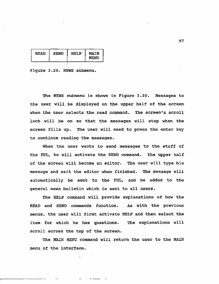
97
READ SEND HELP MAIN MENU
Figure 3.20. NEWS submenu.
The NEWS submenu is shown in Figure 3.20. Messages to
the user will be displayed on the upper half of the screen
when the user selects the read command. The screen's scroll
lock will be on so that the messages will stop when the
screen fills up. The user will need to press the enter key
to continue reading the messages.
When the user wants to send messages to the staff of
the FHL, he will activate the SEND command. The upper half
of the screen will become an editor. The user will type his
message and exit the editor when finished. The message will
automatically be sent to the FHL, and be added to the
general news bulletin which is sent to all users.
The HELP command will provide explanations of how the
READ and SEND commands function. As with the previous
menus, the user will first activate HELP and then select the
item for which he has questions. The explanations will
scroll across the top of the screen.
The MAIN MENU command will return the user to the MAIN
menu of the interface.

98
3.3.7. LOG
Activating this submenu will allow the user to edit or
print the logbook which keeps track of the events of the
session and the time they occur. This logbook will automat
ically be started at the beginning a session. By default,
the logbook will not require any input from the user, but
will simply keep track of events such as when an experiment
is started, stopped, or possibly interrupted. It will also
keep track of when commands of the man/machine and machine/
machine interfaces are used. If an interrupt command is
activated, the command of the machine/instrument interface
which was executed just prior to the interrupt will be
entered into the logbook. This will make the logbook useful
for failure analysis at a later date.
The user may elect to store data collected during the
session in the logbook. He will have the option of printing
it out so that he has a hardcopy of the session's events
which he can review at a later time. Figure 3.21 illu
strates the LOGBOOK submenu.
INCLUDE PRINT HELP MAIN DATA LOG MENU
Figure 3.21. LOGBOOK submenu.

99
The submenu is rather straightforward. If the user
wishes to include data collected during the session in the
logbook, he must select INCLUDE DATA. If he wishes to print
the log, he selects the PRINT LOG command.
The HELP command is provided to answer any questions
the user may have concerning the LOGBOOK submenu, including
printing a copy. As with the previous menus, the user will
first activate HELP and then select the item for which he
has questions. The explanations will scroll across the
bottom of the screen.
3.3.8. UTILITIES
The UTILITY submenu will be selected by the user when
he either wants to temporarily leave the man/machine inter
face and work in VMS, send a message to another user at a
remote site, or transfer the privilege of being the experi
ment commander (EC). He may also use this menu to write his
observations of an experiment into a notebook, and to print
out data, notebook, or help files.
When selected, the submenu displayed in Figure 3.22
will appear on the screen, replacing the MAIN menu.
OPERATING NOTEBOOK SEND PRIVILEGE PRINT HELP MAIN SYSTEM MENU
Figure 3.22. UTILITY submenu.
100
Selecting the OPERATING SYSTEM option will allow the
user to access the RCC's operating system. If the RCC is a
DECnet system, the user will be able to mail messages to
other users who are operating on DECnet systems.
Selecting NOTEBOOK allows the user to write down his
observations throughout the session. The upper portion of
the screen will become an editing screen. When the user has
finished writing his comments, he may return to the UTILITY
submenu by pressing CTRL-Z. The first time the NOTEBOOK is
selected during a session, the user will be prompted for a
filename. Each subsequent editing session will simply be
appended to the NOTEBOOK session. The computer will keep
track of the time at the start and end of each editing
session, and will make a note of the time in the notebook.
The notebook can later be used with the logbook, described
in the previous section, to reconstruct the events of the
session, including the user's observations.
The SEND command will allow the user to send messages
to other users who may be connected to the system. In
contrast to VMS MAIL, messages sent with the SEND command
will be routed through the LCC in the FHL. This will allow
messages to be exchanged between users of the FHL, regard
less of whether or not these systems are connected through
DECnet. After activating SEND, the user will be prompted
for the destination-address and will be asked whether or not

101
he wants to suspend all operations until he receives a
reply. A list of the users connected to the system when
SEND is activated will be displayed on the screen. The user
will simply need to enter "Y" or "N" in response to the
question concerning the suspension of operations until a
response is received. He will then be able to enter his
message on the top half of the screen. When finished, he
may return to the UTILITY submenu be entering a CTRL-Z.
It is foreseen that several RCC's can communicate with
one LCC simultaneously. They then form a team of inves
tigators. However, only one of them is allowed to control
the experiment. He is the experiment commander (EC), while
all the others are experiment observers (EO's). By default,
the first person logging in to the LCC becomes the EC. He
is the one privileged user of the FHL.
Activating PRIVILEGE will result in the display of a
subsubmenu. This menu is illustrated in Figure 3.23.
TRANSFER DISPLAY SHOW HELP LAST MAIN MENU MENU
Figure 3.23. PRIVILEGE subsubmenu.

102
A user may want to transfer the privilege of being the
EC if he is having problems operating an instrument or
conducting an experiment. A different user who is an expert
at operating the instrument, or running the experiment, may
currently be observing the FHL. The EC may send him a
message requesting his help by selecting SEND from the
UTILITY submenu described above. The expert observing the
FHL may offer his assistance, and ask for the privilege of
operating the FHL. The EC may transfer this privilege by
selecting TRANSFER on the PRIVILEGE subsubmenu. He will be
prompted for the address of the user who is to become the
new EC, and will thereafter no longer be able to manipulate
the devices of the FHL. The expert user will now have
complete control of the FHL, and, hopefully, will be able to
fix the problems. This feature can also be used, of course,
for routine transfer of experimental control among inves
tigators.
The former EC is now one of the EO's. He can watch the
experiment being performed by either issuing commands
(selecting menu items) that have display functions only or
by requesting a duplicate of the master screen to be
displayed. Selecting the DISPLAY command will result in a
duplicate screen, and the EO will see everything the EC
sees.
A staff member of the FHL aboard Space Station, or at

103
NASA, will be able to become the EC at any time. This will
require a special password which overrides all other users
and allows the person who has it to use all of the features
of the man/machine, machine/machine, and machine/instrument
interfaces. This password will be used only in emergency
situations which require an expert user to avoid disaster in
the FHL. The EC who loses control of the FHL when this
password is used will be sent a message informing him of the
situation and that he will regain control of the FHL when
the problems are solved.
A user may log onto the system and find that he is not
the EC, because somebody else is currently using the FHL.
Selecting SHOW on the PRIVILEGE subsubmenu will tell him how
many other users are in the queue ahead of him, and who is
currently the EC. This information will be displayed on the
screen.
Activating the item LAST MENU on the PRIVILEGE subsub
menu will return the user to the UTILITY submenu, while
activating MAIN MENU will return the user to the MAIN menu.
The PRINT command on the UTILITY submenu will allow the
user to obtain a hardcopy of any file, including all help
files. When activated, a list of the available files will
be displayed on the top half of the screen, and the user
will be prompted to enter a filename. The help files will
all have the extension HLP, while data files will have the

104
extension DAT, and notebook files will have the extension
NTB.
After activating the HELP command, the user may select
an item to learn more about it. For VMS, SEND, PRIVILEGE,
and PRINT, a brief explanation of the item will be displayed
on the bottom of the screen. If the user needs more
information, he will be advised to consult the manual for
the man/machine interface.
3.3.9. HELP
The operation of the HELP utility used with other menu
items has been extensively described throughout this
document. HELP will perform on the MAIN menu in the same
way as it performs on most of the submenus. When the user
selects HELP, he will be able to obtain brief explanations
of the other items on the menu by activating the respective
item. Since this is the MAIN menu, the explanations for
each of the items will include their submenus. The user
will also be informed that he may obtain more information
about the items on the submenus by activating the HELP
command on each of the submenus.
On each of the menus of the interface, the user can
access a HELP submenu by selecting HELP twice, instead of
selecting HELP followed by different menu item. These HELP
submenus will all have the same appearance, and are illus
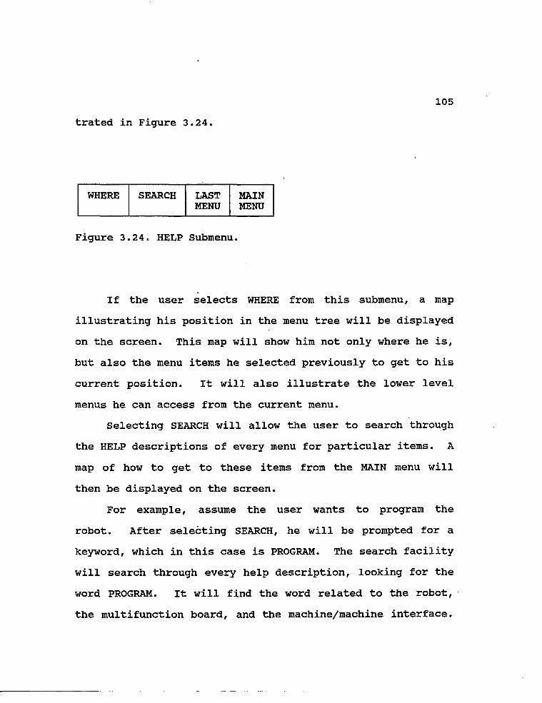
105
trated in Figure 3.24.
WHERE SEARCH LAST MAIN MENU MENU
Figure 3.24. HELP Submenu.
If the user selects WHERE from this submenu, a map
illustrating his position in the menu tree will be displayed
on the screen. This map will show him not only where he is,
but also the menu items he selected previously to get to his
current position. It will also illustrate the lower level
menus he can access from the current menu.
Selecting SEARCH will allow the user to search through
the HELP descriptions of every menu for particular items. A
map of how to get to these items from the MAIN menu will
then be displayed on the screen.
For example, assume the user wants to program the
robot. After selecting SEARCH, he will be prompted for a
keyword, which in this case is PROGRAM. The search facility
will search through every help description, looking for the
word PROGRAM. It will find the word related to the robot,
the multifunction board, and the machine/machine interface.

106
The user will be presented with these three choices, and he
will be prompted to enter one of them. After entering
ROBOT, a map of how to get to the ROBOT PROGRAM submenu,
from the MAIN menu will be displayed on the screen.
3.3.10. EXIT
Activating the EXIT command on the MAIN menu will
terminate the communication link between the two computers.
The FHL/ATF menu illustrated in figure 3.1 will be dis
played. To completely leave the system, and return to the
operating system, the user must select QUIT, and then
DISCONNECT.
3.4 ERRORS
It is certainly possible that errors will develop
during the course of a session. While the user may notice
the possibility of these errors before they actually occur,
and use the INTERRUPT commands to prevent them, this will
not be the standard case. More than likely, errors will
occur and the user will not be aware of them. In these
cases, the man/machine interface must have a way of inform
ing the user that an error has occurred, and also provide a
description of the error.
The machine/machine interface discussed in Chapter 4
includes the command ON ERROR THEN <command>, which is

107
designed to raise a flag when an error occurs and execute
the desired <command>. The setting of this error flag can
be used by the man/machine interface to inform the user of
the occurrence of an error.
When an error- occurs, a caution, warning, or hazard
window will be displayed on the screen of the RCC. A
message informing the user of the nature of the error will
also be displayed. For example, assume the user attempts to
manipulate the robot into a configuration which is not
possible because of joint limitations. The hazardous window
will be displayed on the screen along with the message
"Unable to obtain desired joint position". The block and
the message will remain on the screen until the user
corrects the problem.
The user will also need to be informed when a timeout
error has occurred.. These errors will occur when the LCC
has not received any type of input from the user, or from
one of the instruments, within a certain time limit. For
example, if the user walks away from the system without
disconnecting, then after some selectable length of inac
tivity, the ON TIMEOUT THEN <command> command of the
machine/machine interface will be executed. In this type of
a situation, a window will be displayed on the screen along
with a message asking the user to either respond or log off.
If the user does not respond within an additional selectable

amount of time, his session will be terminated.

109
CHAPTER 4
MACHINE/MACHINE INTERFACE
The machine/machine interface developed in this chapter
is the intermediary language between the remote commanding
computer (RCC) and the local controlling computer (LCC). It
will exist on both machines and will provide a communication
link between the two sites. The commands which the user
enters using the windows of the man/machine interface are
mapped into the lower level set of commands which make up
this interface. These commands correspond to a still lower
level set of commands and programs which make up the
machine/instrument interface, which exists exclusively on
the LCC. The commands and programs of the machine/instru
ment interface are primarily device dependent and, there
fore, must be changed when the equipment of the FHL is
changed. This last interface will be discussed in Chapter
5.
The machine/machine interface, like the man/machine
interface, is device independent. It is similar to the User
Interface Language (UIL), currently being developed for
Space Station. The commands and menus which make up these
interfaces remain the same regardless of the brands of
equipment used in the FHL. For example, if the robot used
in the FHL is switched from a SCORBOT to a HERO 2000, the

110
commands of the machine/machine interface do not need to be
changed.
The commands of the machine/machine interface are low
level in the sense that many commands may be required to
implement the actions of a single menu item from the
man/machine interface. However, in some instances, these
commands will have a- one-to-one correspondence with the menu
items.
The machine/machine interface is designed as a hier
archical command language. The main key (first word)
identifies a command group. There are relatively few such
command groups necessary to capture all activities that are
needed. Each command group is then subdivided into a number
of commands (identified by the second word, the so called
sub-key). Some commands have even subcommands which in turn
can have parameters. For the command
SET ROBOT ARM (DEGREE, [SPEED]),
"SET" identifies the command group, "ROBOT" identifies the
command, "ARM" identifies the subcommand, and "(DEGREE,
[SPEED])" are parameters.
The commands are defined using the Extended Backus-
Naur-Form (EBNF) notation, in which () designates required
parameters, [] indicates optional parameters, and | is used
to separate alternative parameters1. In this document,
terminators are printed in bold type. The commands are

Ill
listed in alphabetical order in Appendix B.
As mentioned in the introduction, the machine/machine
interface for the FHL has many similarities to the same
interface of the atmospheric telescope facility (ATF). When
possible, the parallel nature of the two projects has been
considered in the design. Many of the families of commands
have roots similar to the families of commands required for
the ATF.
The commands listed in this chapter are presented in
the order in which they might be used. The functions of the
commands and how they might be used are also described.
4.1 PREPARATION OF INSTRUMENTS PRIOR TO EXPERIMENTS
4.1.1 ESTABLISHING A CONNECTION
The remote commanding computer (a MicroVax) will be
switched on by the user.
The local controlling computer will remain active at
all times. Eventually, it will be beneficial for the local
computer to remain in a "sleep" state until it is needed so
that energy will be conserved.
The following is a list of the commands required to
establish and confirm a communication link between the local
and remote sites:
CONNECT (ADDRESS) — Establishes communication between remote commanding computer and the local controlling computer. The local computer will respond with a request for user name and password. (ADDRESS) corresponds to the

112
location of the FHL. Once clearance has been approved, a status message is returned to the remote computer informing the user of the presence of any new announcements.
CHECK CONNECTION — Handshaking protocol which ensures that the connection is still present.
HANGUP — Terminates connection.
4.1.2 READ ANNOUNCEMENTS
The user will need to receive updates concerning the
status of the FHL. These updates may include changes in the
services available in the FHL, or they may inform the user
that some of the equipment is unavailable due to required
repairs. Because of the importance of these announcements,
all other commands will be disabled until the user has had
an opportunity to read them.
The user will also be allowed to respond to the
announcements and send messages to the FHL concerning any
problems detected during a session.
Finally, the user will need to be able to read the
announcements any time during a session. The use of this
command has no effect on the status of the other commands,
and therefore will be a different command than the one
described above.
The commands which will accomplish these tasks are
listed below:
SHOW NEWS - Displays any announcements concerning the status of the FHL on the terminal of the remote computer. This command will automatically be executed after the log-in

113
procedure has been completed.
EDIT NEWS - Allows the user to send messages to the FHL concerning any problems encountered during a session.
SHOW STATUS - Displays the announcements from the FHL any time during a session. Initiated by a user request, and does not have any effect on other commands.
4.1.3 CREATE LOG
A logbook will be necessary to keep track of the events
of a FHL session and when they occur, according to the local
computer's clock. This logbook will automatically be
started as soon as a session begins, and will terminate at
the end of the session. The logbook may be used later by
the user to aid in analyzing the session. It may also be
used to aid in failure analysis if problems should develop
with some of the instruments.
The command necessary for opening and closing the
logbook is listed below:
SET LOG = ON | OFF - Opens and closes the logbook which records the actions of the user when they occur, according to the local computer's clock. The logbook will also record the actions of the computers, the robot, and the instruments used in the FHL.
The user may also want to write his observations and
comments of the session into a notebook. This notebook will
be similar to the log because it will keep track of the time
at which an entry is made. The user can later use this
notebook together with the log to recall the events of the
session, and the observations he made of those events.

114
The following command opens and closes the notebook:
SET NOTEBOOK = ON | OFF - Opens and closes the notebook and provides the user with an editor so that he can write his observations and comments of the session. Also keeps track of the time at which each editing session begins.
Commands are also needed for accessing the files on the
computers. These include data, program, notebook, help, and
log files. The files will need to be loaded and saved, and
in some cases, printed or executed. The commands for
accomplishing these tasks are listed below.
LOAD (FILENAME) - Loads the designated file into the computer's memory. Some files will be stored on the RCC, while other files will be stored on the LCC. Data, log, and program files will be stored on both computers. Notebook files will be stored only on the RCC.
SAVE (FILENAME) - Saves the designated file with the given filename.
RUN (FILENAME) - Executes the program with the given filename.
PRINT (FILENAME) - Used to print the logbook, notebook, or any other files the user requests. FILENAME may be entered by the user, but for the logbook, it is not required since the command is called by the LOG submenu. This command acts only on the RCC and is not sent to the LCC.
4.1.4 PRIVILEGE
In the future, the FHL may be accessed simultaneously
by several users from different remote sites. Of course,
not all of the users will be able to actively use the
instruments of the laboratory at the same time. However, it
will be beneficial to allow several users to observe the

115
events as they occur in the FHL while one user actively
controls the instruments and experiments.
Taking this idea a bit further, assume the experiment
commander (EC) has some problems with either an experiment
or some instruments in the laboratory. If one of the
experiment observers (EO's) has more experience with the
experiment, or is an expert at operating the instruments, he
may be able to solve the problem. However, in order to do
so, he will need to become the EC. In this instance, the EC
who has problems will need to give the expert user access to
the FHL so that they may switch roles. This will be
accomplished by using one of the PRIVILEGE commands which
makes a particular user active.
The PRIVILEGE function will also be used to queue users
who want to gain access to the FHL after another user has
started a session. It will, in effect, be a key that is
loaned to the first user who starts using the FHL. All
later users who establish a connection with the laboratory
will only be EO's, and will be asked if they wish to be
placed in a queue in the order in which they formed the
connection. They will be given the option of either staying
connected to the system and assuming a role as an observer,
or they may terminate the connection and the system will
contact them when it becomes their turn to become the EC.
When the first user has completed his session, he will
116
relinquish control of the key to the next user in the queue.
If the next person in the queue does not respond within a
selectable time limit, he will be dumped from the system.
The commands related to the PRIVILEGE function are
listed below:
SET PRIVILEGE (USER ADDRESS) - Designates the EC, and is used when the first user establishes a connection with the system. Later users who attempt to establish a connection will be instructed that they may observe the session, but will be inactive until the initial user returns the "key" to the system. (USER ADDRESS) corresponds to the user who becomes the EC. This command is also used to temporarily transfer the privilege to another user. In this instance, the two users will simply switch their relative positions in the queue.
SHOW PRIVILEGE - returns the user's address who is the experiment commander (EC).
SET QUEUE (USER ADDRESS) - puts the user into a queue until it is his turn to become the EC.
SHOW QUEUE - displays the current contents of the queue, including the addresses of all the users logged into the system.
4.1.5 SENDING TEXT
The user needs to have the ability to send messages to
other users who may be using the system simultaneously.
As mentioned in the previous section, the active user
may run into a problem with some of the equipment in the
FHL. If this occurs, he should be able to send a message to
another user, possibly requesting assistance. The user who
responds to his message may want to have the privilege of
operating the laboratory in order to solve the problem. The

117
initial user would need to enter the SET PRIVILEGE command,
giving the new user's address to the system. The users will
use the SEND commands listed below to communicate with one
another.
SEND (ADDRESS,TEXT) - Sends a message to the user located at (ADDRESS).
SEND/CANCEL - Used to cancel the previous message.
SEND/REPLY (TEXT) - After receiving a message, a user returns a response with this command.
SEND/WAIT (ADDRESS, TEXT) - Sends a message to the user located at address, and inhibits all other functions until a response is received.
SEND/ALL (TEXT) - Sends the same message to all users who are currently logged into the FHL.
4.1.6 ROBOT COMMANDS
When the user requires the robot's services to perform
some type of task, the LCC will first need to check to make
sure the robot is at full power. If the robot is still in
its "sleep" mode, the computer will have to send it a
command to "wake up". The robot should remain in the sleep
mode between sessions so that it conserves energy.
SET ROBOT WAKE - If the robot is in the "sleep" mode, this command will restore it to full power. The robot will go through its calibration procedure to make sure all of its functions are operating properly. If everything performs as expected, the robot's arm will be placed in the home position. If the robot is not in the "sleep" mode, this command will reset the robot, i.e. return it to the home position.
NOTE: It is not yet certain how the sleep and wake functions described above will be implemented. Most likely, an electronic switch will be added to the robot, and it will be

118
activated by the multifunction board in the computer.
Although most robots can be programmed with teach
pendants, the user needs to have the ability to program the
robot's movements from the remote commanding computer. For
this reason, low level commands will exist at the remote
site which address the individual joints of the robot.
These commands will be generic in the sense that they can be
applied to any robot. The commands which will make up this
set are listed below. Both the SET and SHOW commands are
included so that the user will be able to know the position
and orientation of the arm as well as program its movements.
These commands may be used before the experiments begin, but
they can also be used in the middle of an experiment to
correct the robot's"position, if necessary.
SET ROBOT HOME - places the robot's arm in the home position.
SET ROBOT ARM (DEGREES,[SPEED]) - moves the shoulder joint to the angle specified by (degrees), at a rate of [speed].
SET ROBOT ELBOW (DEGREES,[SPEED]) - moves the elbow joint to the angle specified by (DEGREES).
SET ROBOT BASE (DISTANCE,[SPEED]) - moves the robot in a straight path a specified (DISTANCE). Measured in meters. (Only useful if the robot has a base which gives the ability to move in a forward or backward direction).
SET ROBOT LEFT (DEGREES, [SPEED]) - moves the robot in a circle by turning on the left motor until the robot has moved the specified (DEGREES). (Only useful if the robot has a base with wheels which enable it to move in a circular motion).
SET ROBOT RIGHT (DEGREES,[SPEED]) - moves the robot in a

119
circle by turning on the right motor until the robot has moved the specified (DEGREES). (Only useful if the robot has a base with wheels which enable it to move in a circular motion).
SET ROBOT TORSO (DEGREES,[SPEED]) - robot rotates about its torso by (DEGREES).
SET ROBOT FORCE (VALUE) - opens and closes the gripper so that a certain force is exerted.
SET ROBOT GRIP (VALUE) - causes the gripper to open or close to a certain position.
SET ROBOT PITCH (DEGREES,[SPEED]) - moves the wrist to the pitch angle specified by (DEGREES).
SET ROBOT ROLL (DEGREES,[SPEED]) - rotates the wrist to the position designated by (DEGREES).
SET ROBOT YAW (DEGREES,[SPEED]) - moves: the wrist to the yaw angle specified by (DEGREES). (Not available with the robot used in the model FHL).
SET ROBOT WRIST (PITCH,ROLL,YAW,[SPEED]) - wrist rotates about all three axes at the same time. (This will be restricted to pitch and roll for the model FHL).
SET ROBOT SLEEP [HOURS,MINUTES] - puts robot to sleep to conserve energy. [HOURS,MINUTES] are optional. DOES NOT TURN ROBOT OFF. HOURS and MINUTES correspond to the time for which the robot will sleep. Robot is returned to normal operating mode by the command SET ROBOT WAKE.
SET ROBOT CARTESIAN (X,Y,Z,[SPEED]) - instructs the robot to linearly move its end effector a specified distance. Zero distances must be included. Ex: SET ROBOT CARTESIAN (5,0,2) will cause the robot to move its end effector in a straight line 5 cm in the X direction and 2 cm in the Z direction, simultaneously. This command will not be available for the model FHL, since the robot used does not have the ability to move in cartesian space. [SPEED] is optional.
The SHOW commands described below are activated by the
SHOW and DISP items of the ROBOT submenu and the ROBOT
PROGRAM subsubmenu.

120
SHOW ROBOT HOME - returns the angles of all of the arm's joints when the robot is in the home position.
SHOW ROBOT ARM - returns the angle of the shoulder joint in degrees. Displayed on the remote computer's screen.
SHOW ROBOT ELBOW - returns the angle of the elbow joint in degrees. Displayed on the remote computer's screen.
SHOW ROBOT PITCH - returns the wrist's angle of pitch in degrees. Displayed on the remote computer's screen.
SHOW ROBOT ROLL - returns the rotation angle of the wrist in degrees. Displayed on the remote computer's screen.
SHOW ROBOT YAW - returns the wrist's yaw angle in degrees. Displayed on the remote computer's screen. (Not available for the robot used in the model FHL.)
SHOW ROBOT FORCE - returns the force exerted by the gripper in newtons. Displayed on the remote computer's screen.
SHOW ROBOT GRIP - returns the distance between the gripper's fingers. Displayed on the remote computer's screen.
SHOW ROBOT STATUS - returns the state of the robot. The robot will either be in the "sleep" or the "wake" mode. If the robot is in the "sleep" mode for a pre-set amount of time, the remaining time will also be returned.
4.1.7 INSTRUMENT COMMANDS
This set of commands will address the multifunction
board in the FHL. They will also be generic so that they
may be used with any multifunction board.
Many devices will need to be switched on before the
experiments can begin. Electronic switches will be in
stalled so that the multifunction board can power-up these
devices by sending logic high signals (+5v). The commands
listed below will be used to power-up and power-down the
121
devices present in the FHL, and are called by the ON # and
OFF # items of the multiboard submenu.
SET DEVICE = ON I OFF (ADDRESS) - Results in a logic high or low signal being sent to the device located at (ADDRESS). The parallel I/O port of the multifunction board will be used to power-up or power-down the device.
SET ROBOT SWITCH = ON|OFF (ADDRESS) - instructs the robot to position its end effector in front of a toggle switch on an instrument. The robot will then either switch the instrument on or off, depending on the ON|OFF parameter. This command will be used for some instruments which cannot be turned on or off electronically because they are not plugged into the Space Station Information System. The LCC will have to determine which instruments can be turned on, or off, electronically and which will have to be turned on, or off, by the robot.
The user may want to perform a calibration procedure on
an instrument, or test some signal processing electronics,
before an experiment is started. The D/A port of the
multifunction board will be used to send a test signal to a
device, while the A/D port will be used to measure the
device's output. The commands listed below will enable the
user to accomplish these tasks, and are called by the FUNC
GEN and DATA COLL subsubmenus of the multifunction board
submenu.
WRITE DEVICE = ON|OFF (ADDRESS,AMPLITUDE) - Results in a constant voltage being sent to the device located at (ADDRESS). AMPLITUDE is a constant which cannot be outside of the multifunction board's D/A range. (For the LABTENDER, this range is -5v to +4.96v). This command will be disabled until the device located at <address> has been switched on.
READ DEVICE = ONJ OFF (ADDRESS,FILENAME,[SPEED]) - measures the value at the A/D port connected to <address>. An error will result if the' input is not within the multifunction board's A/D range. (For the LABTENDER, this range is +/-
122
5v. This command will be disabled until the device located at (ADDRESS) has been switched on. The collected data is stored in data file FILENAME. If the user did not enter a filename, a default name will be used which will include the type of experiment (pH or ITP), and the date. The extension for the data file will be DAT. ON| OFF either starts or stops the collection of data at a particular address. [SPEED] is an optional parameter that sets the sampling rate and is used only when many samples are being measured.
4.2 EXECUTION OF EXPERIMENTS
A set of high level commands which address the tasks
required for conducting experiments are also necessary.
Again, an attempt will be made to make these commands as
generic as possible so that they do not depend on the type
of robot or multifunction board in the FHL. The commands
described in this section, for the most part, do not
correspond to menu items. Instead, these commands are
called when the user runs an automated experiment such as pH
or ITP. These commands are called by the experiment
programs, and in turn call other programs to complete the
desired tasks. The experienced user, who has a password,
may also use these commands by selecting MACH/MACH INTERFACE
from the program submenu. The commands described in the
last section for the robot and multifunction board are also
used throughout the experiment.
4.2.1 ROBOT EXPERIMENT COMMANDS
The experiments require a set of high level commands
for operating the robot. These commands will instruct the

123
robot to perform certain tasks which are required to
complete the experiments performed in the FHL. These
commands will correspond to low level commands at the local
controlling computer. Since these commands are specific to
the experiments performed in the FHL, the list may become
longer in the future. The commands are used whenever the
user selects a preprogrammed experiment. An experienced
user may also use these commands by selecting the MACH/MACH
INTERFACE item from the PROGRAM submenu of the man/machine
interface.
SET SYRINGE TO (NUMBER) - instructs the robot to position its end-effector above the syringe located at (NUMBER). This position can either be above an instrument or a storage location. The gripper will be in the open position after the command has been executed. (NUMBER) varies from 1 to n, where n is the number of possible syringe locations.
SET SYRINGE GRASP (NUMBER) - instructs the robot to make a cartesian motion corresponding to the syringe (NUMBER). The end-effector will close on the syringe, and the arm will move a short distance in cartesian space to release the locking mechanism which holds the syringe case in place.
SET SYRINGE UNLOCK - instructs the robot to twist the syringe in its grasp the amount necessary to align the notches on the syringe case with the gaps in the adapter base. The necessary amount of rotation will be standard for all the syringe adapters, and will be determined at a later time. The robot then pulls the syringe case out of the adapter base using' the cartesian motion specific for that syringe. This command can only be implemented if the robot has a syringe in its grasp.
SET SYRINGE REPLACE - instructs the robot to make a cartesian motion, replacing the syringe in a receptacle.
SET SYRINGE LOCK - instructs the robot to twist the syringe in its grasp the amount necessary to align the notches on the syringe case with the gaps in the adapter base. Next,

124
the robot pushes the syringe case into the adapter base using cartesian motion, rotates the syringe to lock it in place, and releases it. The necessary amount of rotation will be standard for all the syringe adapters, and will be determined at a later time. This command can only be implemented if the robot has a syringe in its grasp.
SET SYRINGE MOVE (LOCATION #) - instructs the robot to move the syringe to the location specified by (LOCATION #). In most cases, this will position the syringe above a base adapter, which could be attached to an instrument, a fluid or waste reservoir, or a storage shelf. This command can only be implemented if the robot has a syringe in its grasp.
SET SYRINGE FILL (VOLUME) - instructs the robot to pull the syringe plunger the amount necessary to fill the syringe with the desired (VOLUME) . The volume of solution will depend on the experiment and the solution. The LCC will determine the volume by looking up the data in a table. To avoid spills, this command can only be implemented if the syringe case is locked into a-base adapter.
SET SYRINGE EMPTY (VOLUME) - instructs the robot to push the syringe plunger the amount necessary to inject the desired (VOLUME) into the attached inlet port. To avoid spills, this command can only be implemented if the syringe case is locked into a base adapter.
The user will need to have the ability to interrupt the
robot's motion at any time. This may become necessary if
the robot is off target from the desired position. The user
may also decide that the current motion is no longer
required. Regardless, the user will have the ability to:
(1) stop the robot at its present position and reprogram the
robot's motion using the commands described in section
4.1.4, and (2) continue the robot's motion after corrections
have been made. The required interrupt commands are listed
below, and are called by the STOP and CONT items of the
ROBOT submenu.
125
SET ROBOT STOP - causes the robot to suspend its motion until it receives further instructions. The robots position is recorded in memory. This is a priority command, and will not be stored in a command buffer.
SET ROBOT RESUME - causes the robot to resume its activities.
4.2.2 INSTRUMENT EXPERIMENT COMMANDS
This set of commands instructs the multifunction board
to perform tasks required for the experiments. The commands
to turn devices on and off, as well as the read and write
commands described in section 4.1.5 will not be included in
this set.
The command set will be as generic as possible so that
it may be used with any multifunction board. However, every
board may not be able to use all of the commands described
in this set. Different boards will have different capabili
ties, and if a particular board cannot perform the actions
requested by a specific command, the command will be
disabled.
Since the LabTender multifunction board is the board
being used in the FHL, and it is representative of most of
the boards on today*s market, the command set has been
designed to take advantage of its capabilities. Commands
used to control the A/D and D/A ports have already been
described (read, write). The LabTender also has several

126
counters, and their functions are summarized below:
1. Each counter can be used as a frequency generator, and
the output signal may be either a pulsed logic signal or a
more complicated waveform (such as a sine or triangle wave).
2. They can also be used for count accumulation, in which
each counter keeps track of the number of transitions that
occur on its input. The accumulated value can either be
checked by the PCU or compared with an independent value
without disturbing the counting process.
3. Used to count up or down in either binary or binary
coded decimal (BCD). Adjacent counters can be internally
connected to form an effective counter length of up to 80
bits.
4. The first two counters can be used to provide a 24-hour
real-time clock.
The commands described below will take advantage of
these functions. They may actually involve the counters
working with some of the other ports available on the
multifunction board.
SET MULTI COUNT = ON|OFF [FREQUENCY] - causes the counter to count with the given [FREQUENCY]. The [FREQUENCY] parameter is optional, and if not included, will default to once per second. ON|OFF correspond to the START and STOP items on the TIME menu. Enables the SHOW MULTI COUNT command.
SET MULTI PULSE = ON|OFF (ADDRESS,FREQUENCY) - causes the counter located at (ADDRESS) to output a pulsed logic signal with the given (FREQUENCY). ON|OFF correspond to the START and STOP commands of the function generator menu.
127
SET HOLTI WAVEFORM = ON|OFF (ADDRESS,PORT,AMP,[TYPE,FREQ])-causes the counter located at (ADDRESS) to act with a D/A port as a function generator. AMP is a constant value which must be within the range of the multifunction board, TYPE may be either a square, triangle, or sine wave with the specified FREQ. [TYPE,FREQ] are optional, and if they are not included, a constant voltage will result. The phase is zero, and can not be changed.
SET MULTI CLOCK = ON|OFF [INIT,FREQ] - causes the first two counters to begin counting as a real time clock. The default counting increments are one second intervals, but these may be changed by [FREQ]. The initial time of the clock may also be set through the [INIT] option, the default value is 00:00:00. ON|OFF start and stop the clock. Enables the SHOW MULTI CLOCK command.
SET MULTI TIMER = ON|OFF (INIT,[FREQ]) - causes the counters to count backwards from an initial time input by the user. The default counting rate is once per second, but the user may change this using the [FREQ] option. When the timer reaches zero, a message will be displayed on the RCC, and the RCC will emit a. beep. ON starts the timer, and OFF can be used to terminate the counting prematurely.
SHOW MULTI COUNT (ADDRESS) - displays the accumulated count of the counter located at (ADDRESS).
SHOW MULTI "TIME - displays the time according to the realtime clock consisting of the first two counters.
Commands will also be necessary which use the local
controlling computer with the multifunction board to analyze
some of the collected data. The commands listed below are
particularly useful for the isotachophoresis (ITP) experi
ment, and are not included on any menu. They are called by
the ITP program, and may also be used by users who have a
password to write programs using the machine/machine
interface. An example of the use of these commands in an
ITP experiment is given in Appendix C.

128
STORE (ADDRESS,STORE.DAT) - causes the computer to store the sampled values into a temporary file. The samples are collected at the A/D port located at (ADDRESS) . The data collected in this file are the voltage values for the leading and terminating solutions of the ITP experiment, and are used for the calibration of the ITP apparatus. This file is not the same as the data file created by the user.
COMPARE (ADDRESS,VALUE,INTERVAL) - causes the computer to compare the value sampled at (address) with the given (VALUE). This command may be executed once every (INTERVAL) samples and the given (VALUE) will be the second value in the file created by STORE. This command will be needed in the ITP experiment to determine the cutoff points between the leading, sample, and terminating solutions on the ITP response curve.
4.2.3 EXPERIMENT COMMANDS
Through the EXPERIMENT submenu of the man/machine
interface, the user has the ability to select preprogrammed
experiments. He will have a choice between either the pH or
the isotachophoresis experiments. When he selects either of
these, he will also need to choose which solution is to be
tested.
The machine/machine interface must provide commands
which result in the execution of these experiments. They
will be mapped into the machine/instrument interface, where
they will result in the execution of a series of sub
programs. The parameters entered by the user will be passed
to the subprograms. The available "DO" commands which
provide these functions are listed below. Also included in
this list is the CONTINUE command which is used after an
experiment or procedure has been interrupted. Examples of

129
the programs which are called by these commands are given in
Appendix C.
DO pH (SOLUTION #) - Activated when the user selects pH on the EXPERIMENT submenu of the man/machine interface. Solution # is the solution to be tested. The command results in a series of subprograms for the pH experiment being loaded and executed.
DO ISOTACHOPHORESIS (LEADING #, TERMINATING #, SAMPLE #)-Activated when the user selects Isotachophoresis from the EXPERIMENT submenu. Leading #, terminating #, and sample # correspond to the leading, terminating, and sample solutions. The command results in a series of subprograms and commands for the isotachophoresis experiment being loaded and executed.
DO PROCEDURE (PARAMETER #1,PAR #2,PAR #3,PAR #4,PAR #5)-generic DO command which may be used to execute other procedures which combine several programs or commands. This command may be used by the experienced user who has a password giving him the ability to write programs using the machine/machine interface. It will also be used in the future when more experiments are introduced into the FHL.
CONTINUE (PROCEDURE) - used to continue a procedure after it has been interrupted by either the ON ERROR or the ON INTERRUPT commands.
WAIT TIME (TIME) - causes the computer's CPU to wait a certain amount of (TIME) before performing any other tasks.
WAIT INPUT (INPUT) - causes the computer to wait for an input from either the user or an instrument.
4.2.4 ERROR AND INTERRUPT COMMANDS
Finally, commands are required which will be executed
when a particular flag is raised. For example, if an error
occurs in the software, the program being executed should
terminate, and a message should be displayed on the RCC
informing the user of the problem.

130
The user may also detect an error in the positioning of
the robot, or in a particular experiment. He will be able
to temporarily stop the program being executed by issuing an
interrupt command.
A command is also required which reacts to the actions
of the timer. When the timer reaches zero, the user must be
informed. This may be accomplished by displaying a clock on
the screen of the RCC, or by causing the RCC to emit a tone.
It is also necessary to have a timeout command which
raises a flag when an expected response is not received
within a limited amount of time. For example, if for some
reason, the user stops working on the remote commanding
computer, he cannot be allowed to tie up the local con
trolling computer so that no one else can use it. Assuming
no experiments are taking place, if the user who has the
privilege of operating the laboratory does not provide some
type of input to the system within an arbitrary time period,
perhaps five minutes, he will be asked whether or not he is
finished with the FHL. If no response is received after a
shorter time period, the privilege of operating the FHL will
be passed on to another user. The type of input required to
remain active includes any input from the keypad or a mouse.
The timeout command may also be programmed by the user in
certain situations.
The error, interrupt, timer out, and timeout commands
131
are listed below. The error, interrupt, and timeout
commands are priority commands and will not be stored in
command buffers.
ON ERROR THEN (COMMAND) - If an error occurs in a program, the program will be terminated and an error message will be displayed on the RCC. A table look-up scheme will be used to identify the message which matches the particular error.
ON INTERRUPT THEN (COMMAND) - If the user enters an interrupt on the RCC, the (COMMAND) will be executed. The action taken will depend on the command, and a table look-up scheme will be used to match the command and the corresponding action.
ON TIMER OUT THEN (COMMAND) - When the timer finishes counting, or reaches zero, a message will be displayed on the RCC•s screen and the RCC will emit a tone.
ON TIMEOUT THEN (COMMAND) - if no response is received within a limited amount of time, a timeout error flag is raised. Depending on the situation, the preprogrammed (COMMAND) is executed. This timeout command may also be used with instruments, and if they do not respond within a predetermined time limit, an error message will be displayed on the RCC.
A.-i WTS(TRT.TATTROTTR
The user at the remote commanding computer will need
the ability to transfer files to and from the local con
trolling computer. The DECnet-DOS software will provide a
means for accomplishing these tasks. However, since the
implementation has not yet been completed, the available
commands cannot be listed here. It should be noted that
these commands are internal to the DECnet-DOS software, and
therefore, will not be operated on by the scanner, parser,
and command interpreter at the local controlling computer.

132
CHAPTER 5
MACHINE/INSTRUMENT INTERFACE
The machine/instrument interface described in this
chapter is the last portion of software required to remotely
operate the fluid handling laboratory at the University of
Arizona. The man/machine interface and the machine/machine
interface were described in previous chapters and will only
be mentioned briefly in this chapter.
The machine/instrument interface exists on the local
controlling computer (LCC), which is located in the fluid
handling laboratory. It will consist of the commands and
programs which operate the robot and the multifunction
board. It also includes the possibly large programs which
are executed when a preprogrammed experiment is to be
conducted.
The commands are low level and device specific. Each
type of device has different language requirements, and
therefore, when a device is changed, the interface will have
to be changed as well. For example, the multifunction board
currently being used in the fluid handling laboratory (FHL)
is programmed in Basic. If a different multifunction board
is substituted, it may require programs written in Assembly,
Fortran, or some other type of language. Many boards have
their own languages which are developed specifically for

133
their needs.
The commands of the machine/instrument interface are
low level in the sense that many lines of programming code
consisting of hundreds of commands may be required to
perform a simple task. For example, to collect data using
the A/D converter of the multifuncition board, the simple
command READ, which is a command in the machine/machine
interface, will be mapped into a program consisting of
several lines. An example of this program is given in
Appendix D. More complicated commands require even longer
programs.
As another example, consider the case when the user
wants to conduct a pH experiment. He will activate the
EXPERIMENT submenu of the man/machine interface, select pH,
and choose the sample solution. For a pH experiment, the
machine/instrument interface will load one program which
calls many subprograms. Some of these subprograms will
instruct the robot to pick up a syringe, fill the syringe
with the specified sample, and inject the sample into the pH
electrode. They are listed as commands in the machine/ma
chine interface. Other subprograms will use the multifunc
tion board to sample the signal at the output of the pH
electrode and send the collected data back to the user
working on the remote commanding computer. All of these
subprograms may be used individually, as described in the

134
following sections, but for an automated experiment, they
will be used sequentially.
The command interpreter, which also resides on the LCC,
has the responsibility of mapping commands of the machine/-
machine interface into commands and programs of the machine/
instrument interface. This program will be coded in Ada,
and the Ada compiler and support programs purchased from
Meridian Software will be used on the LCC, which is a PC/XT
compatible. At this time, it is not completely known how
the command interpreter will tell the PC/XT to load and
execute programs which may be coded in Basic, but it is
apparent that this will involve software coded in Microsoft
C. The Meridian package supports at least Meridian C, and
examples are provided of how to run different environment
programs using C, but currently, these examples have not yet
been thoroughly investigated.
The experienced user will have access to the commands
and programs of the machine/instrument interface through the
man/machine interface, but he should only need to access
them on rare occasions. In order to do so, he will need to
use an approved password to enter the PROGRAM submenu of the
man/machine interface. He may then program the multifunc
tion board using its language, or program the robot using a
teach pendant.
The teach pendant at the man/machine interface level

135
will be somewhat generic, and therefore will be independent
of the robot used. However, at the machine/instrument
level, the commands which go to the robot, and are eventual
ly stored as a program, will be robot dependent.
The remainder of this document will not actually list
the programs which make up the machine/instrument interface,
but it will include a description of the required functions
of the programs. The document is written in this way so
that it may be used with a number of different types of
devices. The actual programs which perform the tasks will
be developed at a later time, and they will need to be
altered, if not completely recoded, if there are future
changes in the equipment.
5.1 EQUIPMENT
5.1.1 ROBOT
The machine/instrument interface for the robot consists
of the commands which move the individual joints, and the
programs which are used to cause the robot to perform
certain tasks.
A. COMMANDS
For most robots, the command set will include commands
for rotation and movement of the base, torso, shoulder,
elbow, and wrist joints, as well as wrist pitch and yaw, and
the opening and closing of the gripper. Wrist pitch and yaw

136
are up/down and side-to-side movements of the wrist joint,
respectively. The list of commands may also include
variable speed of movement for all motions, and force of
gripper closure. In many cases, the command may include the
joint name, the desired angle, force, or position, and the
relative speed.
For example, to set the shoulder joint of the HERO 2000
robot at forty-five degrees with a relative speed of
movement of 5 (on a scale of 1 to 9, where 9 is fastest),
the proper format of the command is ARM(45,5).
The HERO 2000 breaks up the separation of the gripper's
fingers into ten positions, where 0 is completely closed,
and 9 is completely open. To set the separation at position
5, the correct command is GRIP(5,2), where 2 is the relative
speed of movement. The same gripper may instead be pro
grammed to close on an object exerting a relative force.
The command for exerting a relative force of 4 units is
FORCE(4).
Different robots have different commands for perform
ing the same motion. Therefore, the commands defined in the
machine/instrument interface will need to be changed if the
robot is changed. However, the commands for robot movement
included in the machine/machine interface are generic and
may be used with any robot. The user may select one of
these commands either directly or by activating a cor

137
responding command in the man/machine interface. When one
of these commands is selected, the command interpreter will
map it into the corresponding command of the computer
/instrument interface.
As an example, consider the HERO 2000 as the robot
being used for the model FHL. If the user is operating with
the ROBOT submenu of the man/machine interface and selects
HOME, the machine/machine interface will issue the command
SET ROBOT HOME. For this particular robot, SET ROBOT HOME
corresponds simply to the robot command HOME. The command
interpreter will issue the HOME command to the robot. Other
movements, such as ARM(45,5), will be treated in a similar
fashion.
Neither the HERO 2000 nor the SCORBOT, which have both
been considered for the model FHL, have spherical wrists.
This means that they do not have motion about all three of
the wrist axes. In both cases, the yaw motion has been
neglected, so that the robot's wrist cannot move from side-
to-side. Therefore, the machine/instrument interface for
the robot will not presently include a YAW command. Before
the FHL is implemented aboard Space Station, it will be
beneficial to obtain a robot which has yaw motion capabili
ties, and the machine/instrument interface will need to be
changed.

138
B. PROGRAMS
While some of the commands of the machine/machine
interface, which are designed for robot movement, correspond
to a simple robot command, others map into a whole series of
robot commands. These sets of commands will be packaged as
a program. When the user activates one of these commands,
the command interpreter will map it into a program name.
This program will be loaded into the computer's memory and
executed.
The majority of the programs which are included in the
machine/instrument interface will be created, using a teach
pendant before the FHL becomes functional. The programs
will be stored in the computer's memory using names that
correspond to a specific task. When the programs are needed
during a session, the machine/instrument interface will load
the program into the computer memory and then execute it.
The required tasks of the robot which will be pro
grammed ahead of time are described in detail in "Machine to
Machine Interface for Teleoperation of a Fluid Handling
Laboratory"5, and are summarized below. The commands which
call these programs were also described in Chapter 4.
1. Remove syringe from syringe holder.
2. Move syringe to solution reservoir.
3. Fill syringe with correct solution.
4. Move syringe to inlet port of instrument.

139
5. Inject contents of syringe into inlet port of instru
ment. (Includes pH electrode and isotachophoresis appara
tus) .
6. Move empty syringe to used syringe holder.
7. Deposit empty syringe into syringe holder.
These tasks may need to be repeated more than once to
conduct an experiment.
Some of the tasks listed above may actually involve
more than one program. For example, to remove a syringe
from its respective syringe holder, the robot will need to
execute four separate movements. Special syringe adapters
have been designed at the UofA to compensate for the
microgravity environment which will exist aboard Space
Station, as well as to make the robot's handling of the
syringes feasible. . These adapters allow the syringes to be
locked into place with a rotating motion, and a spring
allows for small errors in the robot's movement. When the
robot is instructed to remove a syringe from its base
adapter, it will first have to move from its home position
to a location directly in front of the target syringe, where
it will stop with its gripper open. The end effector, or
gripper, will then move forward in a straight line and grasp
the syringe. It will unlock the syringe from its base by
rotating it a small amount in the counter-clockwise direc
tion. The spring-lock mechanism will release the syringe,
140
but it will still remain partially in the base adapter. The
gripper will grasp the syringe and completely withdraw it
from the base adapter, moving backward in a straight line.
Each of these movements will be separate programs of
the machine/instrument interface. Splitting the task into
several movements will make it easier to interrupt the
robot's motion, if it is in error. Corrections to its
position may then be completed using the ROBOT submenu of
the man/machine interface, and the robot's task may be
continued. The robot will be preprogrammed to execute each
of these movements using the robot's teach pendant. When
the user requests that a particular task be performed, all
of the programs which make up the motion will be loaded into
the computer's memory and executed in series. The user will
request the execution of these tasks indirectly by selecting
an experiment from the EXPERIMENT submenu of the man/machine
interface.
5.1.2 MULTIFUNCTION BOARD
The portion of the machine/instrument interface
dedicated to the multifunction board will consist mostly of
subprograms which are coded before the laboratory becomes
functional. The board currently used in the FHL is a
LabTender Multifunction Board, and it is programmed in
Basic. Its main features include analog to digital conver

141
sion (A/D), digital to analog conversion (D/A), parallel
input/output (I/O), and a timer. The details of the board
were discussed in Chapter 2.
The board will be used mostly to collect data and to
turn instruments on or off. The board may also be used as a
function generator and a timer, although the experiments
currently foreseen to be conducted in the laboratory have no
immediate need for these functions.
To collect data, the required A/D channels will need to
be initialized. In some instances, the timer may also be
used to start, or finish, the A/D conversion. The collec
tion of data will usually only occur during an experiment,
and therefore, the program which initializes the A/D
converters, and possibly the timers, will be called as a
subprogram when required. The variables passed to this
subprogram will include the channel number where the
sampling is to occur.
The user will indirectly enter the channel number when
he selects the experiment he wishes to conduct. For
example, if the user wishes to conduct a pH experiment, he
will select that item on the EXPERIMENT submenu of the
man/machine interface. The automated experiment will begin
and many programs, including programs for robot tasks, will
be loaded and executed. The output of the pH meter will be
connected to only one A/D channel, and when the subprogram

142
to collect data is loaded into the computer's memory, the
correct channel number will be passed to the subprogram as a
variable. The output of the isotachophoresis apparatus will
be attached to a different A/D channel. When the user
selects this experiment, the channel number will be passed
to the same A/D sampling subprogram that would be used for
the pH experiment. This method will allow one subprogram to
be used for many experiments, with the only change being the
channel number at which the A/D conversion is to take place.
The LCC will then return the data to the RCC,
The user may begin data collection by selecting DATA
COLL on the MULTBOARD submenu of the man/machine interface.
The channel number will be entered by the user after he
finds the number corresponding to the instrument output he
wishes to sample on a table displayed on the screen. In
this instance, the user can also select the input gain of
the channel and the sampling frequency. The input gain will
have a default value of one, but the user may wish to
amplify the incoming signal. The sampling frequency of the
multifunction board is limited to 50kHz, but lower sampling
rates may be implemented by using the counters of the timer.
The subprogram used above for data collection will be the
only program loaded and executed, and the new values for the
input gain and sampling frequency will be passed to the
program, if necessary. If the user does not enter values
143
for these parameters, the default values of unity gain and
50kHz sampling frequency will be used.
As mentioned earlier, the multifunction board can also
be used to turn devices on or off. These devices include
cameras, power supplies, and processing electronics used for
the experiments. The mechanical on/off switches of these
devices will be replaced with electronic switches, and each
device will be connected to a parallel I/O channel.
A device will be turned on when the output of the
channel it is connected to goes high (+5v). When the output
of the channel goes low (Ov), the device will be turned off.
One program, with two variables, will be used to turn all
the devices either on or off. The variables which must be
passed to the program include the channel number (device
number) and the voltage level. These variables will be set
by the user's actions to the prompts of the man/machine
interface. The user may initiate the program either
indirectly by beginning an experiment, or directly by
specifying a device to be turned on or off.
For example, if the user chooses to conduct a pH
experiment, all the associated instruments will be turned on
sequentially. Once the experiment has been completed, the
instruments will be turned off in the reverse order. If, on
the other hand, the user decides to turn on a particular
instrument using the MULTIBOARD submenu of the man/machine

144
interface, he will need to enter the number corresponding to
the device. The "on" portion of the command will tell the
board to output a logic high signal, and the device number
will give the board the channel number at which to apply the
signal. To turn a camera on or off, the user will select
the camera number and either on or off using the CAMERA
submenu of the man/machine interface. The number cor
responding to the camera and the function, on or off, will
be passed to the program as variables. "ON" will result in
a logic high signal being sent to the particular camera,
while "OFF" will result in a logic low signal.
The parallel I/O ports can also be used to drive a
stepper motor. This may be required to rotate a camera
about its base. A logic high signal will increment the
motor, while a logic low signal will decrement the motor by
one step. Each step of the motor will correspond to a
position of the camera. Stepper motors will also be used to
tilt and pan cameras.
Although using the multifunction board as a function
generator is not required for conducting either of the two
experiments, it may be useful in the future. The user will
select the type of waveform to be generated using the
MULTIBOARD submenu of the man/machine interface. The
possible waveforms include triangle, sine, and square waves,
as well as a signal of constant amplitude, and a logic pulse

145
train. After selecting the waveform, the user will also
need to select the amplitude and frequency, or in the case
of the constant signal, simply the amplitude. For a logic
pulse train, he will only need to select the frequency.
Finally, he will need to select the D/A channel which will
output the signal. Each channel will be connected to a
specific instrument, and the user will have access to a
table listing these connections.
Programs will exist for each type of waveform and will
be loaded when they are needed. The variables which need to
be passed to the programs include the amplitude and frequen
cy of the waveform, and the D/A channel number. The program
will be executed when the user selects the START item of the
subsubmenu, and will terminate when the user selects STOP.
The program will need to periodically check for an interrupt
flag which will indicate that the program should be ter
minated.
The user will also be able to use the board's timer as
either a counter or a clock. When he selects COUNTER from
the TIME subsubmenu of the man/machine interface, a program
which counts, starting from zero, in intervals set by the
user will be loaded into the computer's memory. Execution
of the program will not begin until the user selects START
from the same menu. The counting will be terminated when
the user selects STOP, and the final value will be returned
146
to the remote commanding computer.
If the user selects CLOCK from the sub submenu, a
program will be loaded into the computer's'memory that uses
the board's counters as a twenty-four hour clock. The user
will be prompted to enter the initial time, and the program
will not be executed until the user activates START. The
program will terminate when STOP is selected. The user may
also enter a counting frequency different then once per
second.
More experienced users may program. the multifunction
board themselves by using the PROGRAM submenu. When this
menu item is selected, the local controlling computer will
become the master computer, and a Basic compiler will be
activated. The user may then program the board to perform a
variety of functions. A sample program can be found in
Appendix D of this thesis. More sample programs may be
found in the LabTender's User's Manual9.
The machine/instrument interface described in this
chapter includes the commands and programs required to make
the instruments and the robot conduct the available experi
ments of the FHL. The interface consists of commands which
are unique to the equipment of the laboratory. If this
equipment changes in the future, the commands and programs
which make up the interface will also need to be changed.
This fact makes the machine/instrument interface quite

147
different from either the man/machine interface or the
machine/machine interface, which are both essentially device
independent.
The commands which make up the machine/instrument
interface are also of a lower level than the commands of
either the machine/machine or the man/machine interface.
This is because one command at the man/machine level may
correspond to ten commands at the machine/machine level, and
these may correspond to fifty commands, or a hundred line
program, at the machine/instrument level.
Sample programs of the machine/instrument interface are
listed in Appendices C and D. These appendices include the
commands required to conduct an Isotachophoresis experiment,
as well as a program illustrating the use of the multifunc
tion board as an A/D converter. Other programs will
certainly be required for the FHL, and this chapter has de
scribed what programs are necessary to implement the
commands of the man/machine interface and the machine/ma
chine interface.

148
CHAPTER 6
SAMPLE SESSION OF THE REMOTE OPERATION FLUID HANHHimargABORATORY
This chapter describes an example session in which the
user, a scientist who has limited experience with computers,
wishes to conduct an isotachophoresis experiment. It is not
the intent of this chapter to give examples of how every
command described in the preceding chapters can be used.
Instead, this chapter will present examples of several
commands which may be used to conduct an isotachophoresis
experiment. It also explains how these commands, selected
from the man/machine interface, will activate commands of
the machine/machine interface. For the commands not
described in this chapter, a direct extension of the
relationships described here is possible.
Assume the scientist has a technician at his side who
has experience manipulating robots and programming them via
teach pendants. The user first logs onto the system, using
his password, and enters the fluid handling laboratory (FHL)
system. Any NEWS announcements concerning the FHL are
displayed on the screen and he is given time to read them.
He is then informed that he is the only user to request
access to the laboratory, and therefore, is given the
privilege of operating it. If he was not the first user to
request access, he would be informed of his position in the

149
queue and that he may observe the activities of the FHL. He
will also have the option of leaving the session, but
retaining his place in the queue. The LCC will then inform
him when he gains the privilege of becoming the experiment
commander (EC). If he chooses to remain logged into the
system, he would have the ability to use the passive menu
items such as displaying the robot's joint angles and the
collected data. He would also be free to write in the
logbook, send messages to other users, and use the help
facilities of each menu. If he desires, he can also receive
an exact duplicate of the EC's display and observe his
actions and data.
Once the user has the privilege of operating the FHL,
he may begin the isotachophoresis experiment. As soon as
the session begins, the FHL's logbook will automatically be
activated. This logbook will keep track of all the events
which take place throughout the session, and the time at
which they occur. The user may later print a copy of the
logbook so that he has a copy of the session's events for
his records. If the user wants to include the data col
lected during the session in the logbook, he will first need
to select LOG from the MAIN menu. The LOG submenu will
replace the MAIN menu on the screen. He will then be able
to select INCLUDE DATA from the LOG submenu. The two menus
are shown in Figure 6.1.

150
EXPER ROBOT CAMERA MULTI PROGRAM NEWS LOG UTIL HELP EXIT BOARD
INCLUDE PRINT HELP MAIN DATA LOG MENU
Figure 6.1. MAIN menu and LOG submenu.
The user may also want to adjust the images of the
laboratory cameras before he begins the experiment. The
images of the instruments will be displayed on the televi
sion monitor. He may select any available combination of
images that he desires by using the CAMERA submenu. The
MAIN menu and the CAMERA submenu are illustrated in Figure
6.2. Recall that a table listing the available cameras and
their possible functions will also be displayed on the
screen.
EXPER ROBOT CAMERA MULTI PROGRAM NEWS LOG UTIL HELP EXIT BOARD
ON # OFF # VIEW # PAN # TILT # LENS # ZOOM # HELP MAIN MENU
Figure 6.2. MAIN menu and CAMERA submenu.

151
The table will include information concerning which
cameras are on or off, which are currently being viewed, and
which have the ability to change lens, zoom, or tilt and pan
angles. It will also give a brief description of the
location of the camera and what items are in the camera's
viewing range. After studying the table, the user will be
able to decide which cameras he wants on, and which he wants
to view. He will need to select the ON and VIEW items and
enter the corresponding numbers. The selection of these
commands will activate the SET DEVICE = ON (ADDRESS)
commands of the machine/machine interface, where (ADDRESS)
corresponds to the camera number, or location. The multi
function board will output logic high signals (+5v) to the
cameras, turning them on, and the television monitor will
split into' the desired number of screens so that the images
of the selected cameras may be viewed.
After viewing the images from the selected cameras, the
user may decide that a particular camera needs to be
adjusted. The methods for operating the pan, tilt, and zoom
commands were described in Chapter 3. When the user selects
any of these items from the menu, speed, movement, and angle
blocks will appear on the screen which the user may use to
manipulate the camera. These blocks are reprinted in figure
6.3, where (a) is the speed block and speed indicator, (b)
is the increment angle block, and (c) is the pan movement

152
block.
II
SPEED INDICATOR
/ \ FAST
\ / SLOW
II
INCREMENT INDICATOR
/ \ HIGHER
\ / LOWER
SPEED BLOCK (a)
INCREMENT ANGLE BLOCK (b)
Figure 6.3. Camera blocks for pan movement.
PAN BLOCK (c)
The user will need to input the number corresponding to
the desired camera. Depending on which arrows are acti
vated, either the SET DEVICE = ON or the SET DEVICE = OFF
commands will be activated at the machine/machine interface
level. This results in the multifunction board sending a
logic high (+5v) or logic low (Ov) pulse to the actuator
corresponding to the selected movement of the desired
camera. The movements will be executed on an incremental
basis.
For example, each activation of the up arrow of the
TILT command will raise the camera angle by an amount equal
to the incremental angle set by the user. 'The other
commands will have similar effects.
Once the user is satisfied with the images on the

153
screen, he will need to return to the MAIN menu. He may do
so by selecting the MAIN MENU item of the CAMERA submenu.
The MAIN menu illustrated in Figure 6.4 will be displayed on
the screen. To begin the isotachophoresis experiment, the
user will need to select the EXPERIMENT submenu. The
submenu will appear on the screen, replacing the MAIN menu.
EXPER ROBOT CAMERA MULTI PROGRAM NEWS LOG UTIL HELP EXIT BOARD
PH ISOTACHO INTER CONT RESET DATA HELP MAIN MENU
Figure 6.4. MAIN menu and EXPERIMENT submenu.
The user will need to select the isotachophoresis (ITP)
item to begin the experiment. Once he selects this item,
the ITP subsubmenu will be displayed on the screen. It is
illustrated in figure 6.5.
SAMPLE LEADING TERMINATING FILE HELP LAST MAIN SOLUTION SOLUTION ' SOLUTION NAME MENU MENU
Figure 6.5. ISOTACHOPHORESIS subsubmenu.

154
Recall from Chapter 3 that the user will choose the
desired solutions from a lower level menu listing the avail
able solutions. From this list, the user will need to
select the leading, terminating, and sample solutions. The
functions of the leading and terminating solutions were
discussed in Chapter 2, and they will not be repeated here.
All of these numbers will be passed to the DO ISOTACHO-
PHORESIS (LEADING #, TERMINATING #, SAMPLE #) command of the
machine/machine interface, and in turn, passed to the
subprograms and commands which make up the isotachophoresis
experiment program. The (LEADING #, TERMINATING #, SAMPLE
#) portion of the DO command corresponds to the numbers of
the selected solutions.
The user will also need to select the name of the file
in which the collected data is to be stored. This file will
have a default extension of DAT, but the user may override
this name if he wishes.
The experiment will begin, and the robot will move to
pick up the first syringe. The user will be able to watch
the robot's movements on the television monitor. As men
tioned previously, the automated experiment consists of a
series of subroutines which may be interrupted at any time
if the user detects a problem.
If the user wishes to observe the data on the upper
portion of the computer screen, he will need to select the

155
format in which it is displayed. First he will need to exit
the ISOTACHOPHORESIS subsubmenu by selecting LAST MENU. The
EXPERIMENT submenu will reappear on the screen, and he will
need to select DATA of the EXPERIMENT submenu. The menu il
lustrated in figure 6.6 will replace the EXPERIMENT submenu
on the screen.
FILE REAL X-Y TABLE # OF HELP LAST MAIN NAME TIME PLOT PLOTS MENU MENU
Figure 6.6. DATA subsubmenu.
The user has the option of observing the data as it is
collected (REAL TIME) or observing data which was previously
stored in a file. Of course, he may also do both. For
example, if he conducted a similar ITP experiment earlier
and wants to compare that data with the data collected from
the present experiment, he could view both sets of data on
the screen simultaneously by selecting # OF PLOTS and
responding to the prompt with two (2).
Assuming the user wishes to view the data as it is
being collected, he will need to select REAL TIME from the
DATA subsubmenu. ' The data will be stored in the designated

156
file at the same time that it is displayed on the screen.
The user will also have to select the format in which
the data is to be displayed. He has the option of plotting
the data on an X-Y plot, listing the data in a table, or
both. The details of the format of the plots and the tables
were described in Chapter 3.
Since this chapter is describing a sample session, and
its purpose is to show how the software might be used,
assume the user notices an error at some point during the
experiment. Perhaps the robot's positioning of a syringe is
wrong and further movement will result in damaged equipment.
The user should be watching the television monitor at all
times, and will be able to see the development of this type
of problem before it causes irreparable damage.
When the user notices the error in the positioning of
the syringe, he can stop the experiment by selecting
INTERRUPT of the EXPERIMENT submenu. This is a priority
command which will override any subprograms which are
currently running. The robot's motion will stop, and a
window will pop up on the screen listing the lines of code
surrounding the interrupt point. After analyzing the code,
the user can decide where the error occurred and reposition
the robot's end effector, using the ROBOT submenu. He will
first need to return to the MAIN menu.

157
STOP CONT HOME TORSO ARM ELBOW PITCH ROLL GRIP SHOW DISP HELP MAIN MENU
Figure 6.7. ROBOT submenu.
Figure 6.7 illustrates the ROBOT submenu which will
appear on the screen after the user selects ROBOT on the
MAIN menu. The user will need to determine which joints
need to be manipulated to obtain the correct position. In
this sample session, the scientist should allow the tech
nician who has experience with robots to make the correc
tions.
Assuming the user decides to first move the syringe
back from its present position, he will need to move the
elbow and shoulder joints iteratively, in small increments.
The speed, movement, and increment angle blocks for these
joints will appear on the screen when he selects a joint.
As an example, assume he first decides to move the shoulder
joint. He will select ARM, and the speed, increment angle,
and movement blocks will be displayed, as illustrated in
Figure 6.8.
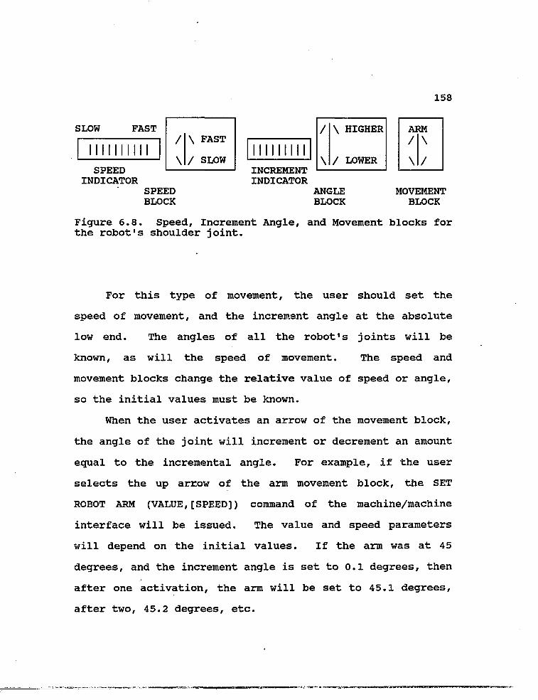
158
SLOW FAST
II
SPEED INDICATOR
\ PAST
/ SLOW II
INCREMENT INDICATOR
\ HIGHER
/ LOWER
SPEED BLOCK
ANGLE BLOCK
ARM / \
\ /
MOVEMENT BLOCK
Figure 6.8. Speed, Increment Angle, and Movement blocks for the robot's shoulder joint.
For this type of movement, the user should set the
speed of movement, and the increment angle at the absolute
low end. The angles of all the robot's joints will be
known, as will the speed of movement. The speed and
movement blocks change the relative value of speed or angle,
so the initial values must be known.
When the user activates an arrow of the movement block,
the angle of the joint will increment or decrement an amount
equal to the incremental angle. For example, if the user
selects the up arrow of the arm movement block, the SET
ROBOT ARM (VALUE,[SPEED]) command of the machine/machine
interface will be issued. The value and speed parameters
will depend on the initial values. If the arm was at 45
degrees, and the increment angle is set to 0.1 degrees, then
after one activation, the arm will be set to 45.1 degrees,
after two, 45.2 degrees, etc.

159
Of course, all this will occur in a short time. If the
user wants to move the joint a large amount, he will need to
increase the increment angle. He may also select the appro
priate movement arrow many times in quick succession. When
he is finished with one joint, he may move on to the next
joint by selecting the corresponding item on the ROBOT
submenu.
After the user has moved the syringe to the correct
position, he will need to return to the EXPERIMENT submenu
to continue the experiment. He will also need to decide
which lines of code need to be either repeated or skipped.
He will then need to select the program line from which the
program will continue. To continue the experiment, he will
select CONTINUE from the EXPERIMENT submenu.
Assuming the ITP experiment continues without any more
errors, the user will be able to observe the data on the
computer screen as it is being collected. If he notices
anything that he wishes to comment about, he may do so by
activating the UTILITY submenu. This submenu is illustrated
in figure 6.9.
OPERATING NOTEBOOK SEND PRIVILEGE PRINT HELP MAIN SYSTEM MENU
Figure 6.9. UTILITY submenu.

160
The user may begin writing his comments and observa
tions in the notebook by selecting NOTEBOOK from the UTILITY
submenu. This will activate the SET NOTEBOOK = ON command
of the machine/machine interface, and the upper portion of
the computer screen will temporarily become an editor. When
the user is finished, pressing CTRL-Z on the keyboard will
exit him from the editor. This will activate the SET
NOTEBOOK = OFF command of the machine/machine interface, and
whatever was being displayed on the screen prior to the
activation of the notebook will be redisplayed.
After the user has finished the ITP experiment, and is
satisfied with the results, he may terminate the session and
exit the system. This is accomplished by first returning to
the MAIN menu, which is illustrated again in figure 6.10.
EXPER ROBOT CAMERA MULTI PROGRAM NEWS LOG UTIL HELP EXIT BOARD
Figure 6.10. MAIN menu.
The user terminates the session by selecting EXIT. He
is given an opportunity to reverse his decision in the form
of a question which prompts him for either a "y" or "n"

161
response. When the user confirms his decision to end the
session, the HANGUP command of the machine/machine interface
is activated, and the user is disconnected from the fluid
handling laboratory.

162
CHAPTER 7
DEFICIENCIES OF THE SYSTEM
The fluid handling laboratory which has been described
in the preceding chapters is intended to be a small scale
model of the fluid handling laboratory which will be aboard
the proposed U. S. Space Station. As with the development
of any large project, many problems have been encountered
throughout the design of the simulated fluid handling
laboratory (FHL). The intention of this chapter is to
describe these problems, discuss the solutions which have
been implemented for some of these problems, and to discuss
possible solutions for problems which still remain. Since
the design of the FHL has not yet been completed, more
problems may be encountered in the future. Obviously, these
unknown problems cannot be addressed at this time.
The equipment being used in the FHL contains some
deficiencies which have created problems throughout the
design of the laboratory. Many of these problems have been
solved, but others remain which must be completely resolved
in the future. These problems are described in the next
section.
Problems involving software have also been encountered.
These include restrictions of OASIS which have affected the
design of the man/machine interface. These restrictions and
the other problems will also be discussed in this chapter.

163
7.1 EQUIPMENT
7.1.1 ROBOT
Two robots have been tested and evaluated for use in
the simulated fluid handling laboratory (FHL). These are
the HERO 2000 and the SCORBOT robots. Both robot arms
consist of three links and an end-effector, or gripper, and
have five degrees of freedom. These degrees of freedom
include rotation about the torso, shoulder and elbow
rotations, and rotation and pitch of the wrist. However,
both arms are missing the third motion required of a
spherical wrist, namely the yaw motion. This means the
robot's wrist (and therefore its lower arm) must approach
objects from a direction which does not require yaw action
to grasp the object.
To compensate for this deficiency, the front of the
shelves in the instrument racks have been modified so that
they are concave. Since the robot can turn about its torso,
this modification enables the robot to approach any object
on a shelf with the required angle of ninety degrees.
Although this is a rather simple solution, it is not an all-
purpose solution. The robot which is eventually used in
Space Station will definitely need to have a spherical
wrist.
A second problem encountered with both robots was that

164
they could not be programmed for cartesian movements in
space. There are no commands provided with the robots which
facilitates this type of movement. For cartesian movement
in space, the robot needs to have the ability to perform
translational movements which will allow it to move its end-
effector a specified distance in the X, Y, and Z planes.
Cartesian movements in space are required in many instances
in the experiments of the FHL. The retrieval and storage of
syringes, as well as the injection and withdrawal of the
plungers of the syringes are examples of this motion.
In attempting to solve this problem, it was eventually
determined that pseudo-linear motions could be obtained by
moving the shoulder and elbow joints sequentially and
repeatedly in small increments. These movements were stored
as programs using the teach pendant. When they were exe
cuted, the arm moved forward, but its trajectory consisted
of a series of quick stops and starts which resulted in a
ripple motion rather than a true straight line. For the
short distances involved with retrieval and storage of a
syringe, it was determined that this motion would be accep
table. However, for movements which require accuracy, such
as the injection of fluids, the programmed pseudo-linear
motions are insufficient. Alternative ways of retrieving
and injecting fluids will be discussed in section 7.1.3.
Although the pseudo-linear motions were programmed

165
using a teach pendant, it is readily apparent that it would
be very difficult for a user operating the robot remotely to
achieve the same linear motions. For now, the motions will
be preprogrammed as subprograms for an experiment. However,
in the future, users may find it necessary to use the robot
for linear motions. In these instances, programming the
robot on-line to move over a short path made up of several
points in close proximity will not be practical.
Another possible solution to the problem of linear
motion is using a linear slide table which the robot sits
on. The manufacturers of the SCORBOT robot produce such a
device. Its purchase and evaluation are expected in the
near future.
A final problem with the SCORBOT which will need to be
addressed in the selection of a robot for SPACE STATION is
the fact that it does not contain its own microprocessor.
Therefore, all of the programs which operate the robot must
be stored and executed on the LCC. The LCC's processor is
also occupied when the robot is placed in the teach pendant
mode. If the robot had its own processor, it would not only
be faster since less data would have to be transmitted over
the RS-232 cable, but the LCC would also be free to work on
other tasks while the robot executed its own programs.
Throughout the evaluation of the two robots it was
evident that the SCORBOT was sturdier, more accurate, and

166
more reliable than the HERO 2000. Although the HERO 2000
does have its own microprocessor (an 8088), the advantages
of the SCORBOT still outweighed the advantages of the HERO.
For these reasons, it has been decided that the SCORBOT is
the robot which will be used in the model FHL.
All of the problems described in this section may be
avoided by using a more expensive robot. A more expensive
robot will also be more accurate, which will' be necessary
for more intricate experiments which may take place aboard
the U.S. Space Station.
7.1.2 MULTIFUNCTION BOARD
A disadvantage of the LabTender multifunction board
used in the model FHL is that some functions require special
jumper configurations before they can be used. The func
tions used in the FHL did not require jumpers to be changed,
but if they had, this would be a very serious problem. The
problem may be avoided in the future by using a more
expensive multifunction board which uses software switches
for changing functions rather than hardware such as jumpers.
7.1.3 INSTRUMENTS
Since the FHL is a model of the FHL aboard the proposed
Space Station which will operate in a microgravity environ
ment, the same environment had to be considered in the
development of the FHL at the UofA. The most obvious con
167
sideration involved the storage of syringes. The syringes
needed to be locked into a permanent fixture, but still
needed to be easily handled by the robot.
The solution to this problem was the design and
production of a syringe adapter which includes a case
surrounding the syringe and a locking, stationary base. The
syringe plugs into the base and is locked into place by
twisting the syringe a half turn. The plunger of the
syringe was also modified to make it easier to handle for
the robot. The syringe adapter and base have been used
extensively with the robot, and have proven to be a good
solution.
As mentioned in 7.1.1, the programmed robot movements
developed for linear motion did not result in the high
accuracy motions required for the injection of fluids. For
this reason a syringe driver has been developed. The driver
consists of a stepper motor and a drive screw attached to a
block. The syringe is placed in the apparatus and the head
of the plunger is locked into the block. The plunger can be
accurately moved in or out of the syringe by advancing or
retracting the block attached to the drive screw. The drive
screw is manipulated by the stepper motor, which is driven
by voltage signals from the multifunction board in the
LCC11.
The possibility of using computer controlled pipettes

168
instead of the syringes is also being considered. At this
time, documentation describing the pipettes has been
reviewed, but no pipettes have been obtained for evaluation.
7.1.4 LOCAL CONTROLI-Twr: rnMPQTER
The PC/XT which functions as the local controlling
computer for the FHL is sufficient to handle the experiments
conducted in the model FHL. Although the operating system
which resides on the LCC does not support multitasking, the
Meridian Ada software package which has been purchased does
have this capability. Multitasking allows the LCC to
conduct experiments, operate the robot, and communicate with
the RCC simultaneously, and is certainly a required feature.
However, it will still be beneficial to upgrade this
computer for the fluid handling laboratory aboard Space
Station. The LCC will need to be considerably faster, and
will need greater capabilities. A MicroVax, SUN Worksta
tion, or a PS/2 Model 80 should be sufficient.
7.2 SOFTWARE
7.2.1 OASIS
One of the earliest problems encountered with OASIS was
that of pull-down menus. It would have been preferable to
design the man/machine interface with pull-down menus which
allowed the user to work in more than one menu area at a
time. This would allow the user to move around the various
169
menu fields very quickly without having to close each menu
along the way. However, since OASIS does not support pull
down menus which allow the user to work on more than one
item at a time, the man/machine interface had to be de
signed, as it is described in this document, with menus
which replace each other when activated. The user will need
to exit each menu by selecting either LAST MENU or MAIN MENU
before he can begin work in a different menu.
If OASIS is updated in the future to include pull-down
menus, it should be an easy transition to upgrade the menus
currently supported by the man/machine interface.
The man/machine interface for the FHL, as it has been
described in this document, is loaded into the RCC's memory
after FHL is selected from the FHL/ATF menu. If the user
instead selected ATF from this menu, then the man/machine
interface for that project would be loaded into the RCC's
memory. This method of loading the two similar, but
separate, databases which make up the interfaces will allow
a user to easily switch between the two projects. If the
user is working on the ATF and wants to switch to the FHL,
he simply needs to return to the FHL/ATF menu and select
FHL. The database for the man/machine interface of the FHL
would then replace the database for the interface of the ATF
in the RCC's memory.
Unfortunately, OASIS currently will not allow this type

170
of switching between interfaces. The menus which can be
produced with OASIS cannot be used to load databases. In
stead, they are restricted to calling lower level menus.
This means that if the FHL/ATP menu is used to access the
MAIN menus of the man/machine interfaces for both the FHL
and the ATF, both databases, and therefore interfaces, must
be previously loaded into the RCC's memory. This will not
only require a tremendous amount of memory, but will also
make the use of either interface very slow. It is hoped
that this restriction of OASIS can be eliminated.
Another restriction of OASIS is the fact that it can
currently receive only telemetry information, which means
that all incoming data must be in numerical format. This is
a problem when communication between two parties is desired.
For example, if two users at different remote sites wish to
send messages to each other, OASIS does not support any
means through which they may communicate with text. Of
course, if all users are working with DECnetted VAX systems,
they may bring up an OASIS window and communicate through
the VAX mail or phone facilities. There is no reason to
think that all future users of the fluid handling laboratory
aboard the U.S. Space Station will be connected through
DECnet, or will be using VAX systems, but similar function
ality must be provided. Currently, the University of
Colorado is migrating the OASIS software to SUN Worksta

171
tions.
As a second example, consider NEWS messages described
in Chapters 3 and 4 which may be sent by the astronauts
aboard Space Station to the remote users. These messages
will consist of information on the status of the equipment
used in the FHL, or explain procedures for accessing new
equipment and experiments. OASIS will have to have the
ability to receive these messages, which will be transmitted
by the local controlling computer. Again, there is current
ly no reason to believe that the LCC will be a VAX system
with mail facilities.
A possible solution is to code the messages as numeri
cal data which can then be received by OASIS. Software will
need to be written inside of OASIS which decodes these
messages into the original text. Although this solution
would appear sufficient, it is hoped that OASIS might be
modified in the future to have the ability to receive text.
7.2.2 COMMDNICATION BETWEEN THE LOCAL CONTROT.T.TNG COMPUTER AND THE REMOTE COMMANDING COMPUTER
DECnet-DOS is the software package responsible for the
proper communication protocol between the remote commanding
computer (RCC), a MicroVAX, and the local controlling
computer (LCC), a PC/XT. It resides on the LCC and allows
file access, file transfer, and task-to-task communications
between the two computers. However, the package has not yet

172
been implemented, so the details of its operation are not
fully known. It is hoped that the software will facilitate
all the communication necessary between the computers and
will allow the transfer of the commands of the machine/
machine interface. After the software has been implemented
and evaluated, its benefits and limitations will be known.
It has also not yet been decided how priority commands
will be implemented. These commands include the SET ROBOT
STOP, ON INTERRUPT, ON TIMEOUT, and ON ERROR commands of the
machine/machine interface, as well as the INTERRUPT command
of the EXPERIMENT menu of the man/machine interface. All of
the priority commands are designated in Appendices A and B.
When an error occurs, or the user interrupts a proce
dure using the man/machine interface, these commands will be
activated and must have priority over all other commands.
They must bypass whichever commands or subprograms are in
the queue and be transferred from one computer to the other
with minimal delay. It is possible that DECnet-DOS will
provide a solution to the implementation of these commands,
but it will not be known for certain until this software has
been evaluated.
It is also unknown at this time how the privilege
commands discussed in the previous chapters will be imple
mented. The LCC will somehow need to keep track of who has
the privilege key, and who is next in the queue to receive
173
it. The LCC will also be responsible for transferring the
privilege key between users when this request is made. Most
likely, software will need to be developed which controls
the privilege key and keeps track of who should have it and
when. Again, it is possible that DECnet-DOS will provide a
means for transferring the key between users.
7.2.3 MACHINE/INSTRUMENT INTERFACE
The scanner, parser, and command interpreter which
reside on the LCC and were discussed in Chapter 4 will be
coded in Ada. For this reason, the Meridian Ada compiler
and optimizer have recently been purchased, which currently
seems to be the only validated Ada compiler for PC/XT1 s.
The scanner and parser are responsible for recognizing the
commands of the machine/machine interface, while the command
interpreter is responsible for mapping them into the
commands and programs of the computer instrument interface.
The machine/instrument interface will include programs
written in Basic, programs and commands intended for the
robot, and DOS commands used for tasks which take place on
the LCC.
Unfortunately, it has not yet been determined exactly
how the command interpreter, which is written in Ada, will
call Basic commands' and programs, as well as robot commands
and programs, and DOS commands. The Ada compiler being used

174
does interact with Meridian C software and Assembly lan
guage, and these may be called upon to solve these problems.
More should be known about the Ada compiler and how these
problems will be resolved in the near future.

175
11. E. Raize, "Syringe Driver Assembly for Automated Fluid Handling Laboratory", Technical Report TSL-012/88, Visiting Scholar, Electrical and Computer Engineering Department, University of Arizona, Tucson, AZ, May 1988.

175
CHAPTER 8
CONCLUSIONS AND RECOMMENDATIONS
This document has described the software designed for
the remote operation of a fluid handling laboratory. The
laboratory for which it was designed is intended to be a
small scale model of the fluid handling laboratory which
will be aboard the proposed U.S. Space Station. The model
is currently being developed at the University of Arizona,
and although the software was primarily designed for this
model, the needs and requirements of the operation of a
similar laboratory, aboard' Space Station have been con
sidered. The software therefore exceeds the current
requirements of the model fluid handling laboratory, and
some portions of it do not need to be implemented at this
time. It consists of a man/machine interface, a machine/-
machine interface, and a machine/instrument interface.
The man/machine interface consists of a series of
hierarchical menus which are activated by a mouse, and it
resides on the remote commanding computer. The interface is
generically designed so that it may be used with a variety
of equipment, and consists of high level commands. It is
intended to give the operator of the system a convenient way
to operate the equipment and experiments of the laboratory
without requiring much experience. The interface also gives

176
the user considerable freedom in the operation of the
laboratory, and allows authorized users to program the
equipment.
The machine/machine interface resides on both the
remote commanding computer and the local controlling
computer. It incorporates intermediary level commands which
map the commands of the man/machine interface into the
commands and programs which make up the machine/instrument
interface. The commands are also independent of the
equipment used in the laboratory. The interface, for the
most part, has been designed as consisting of families of
commands. Each family of commands has one root command such
as SET or SHOW. This design makes the commands more organ
ized and greatly facilitates the HELP system.
The machine/instrument interface is the software which
runs the experiments and operates the equipment. It resides
completely on the local controlling computer and is depen
dent on the equipment used in the laboratory. It consists
of the low level commands and programs which operate the
multifunction board and the robot. Since these commands and
programs are device dependent, they are not listed in this
document. Instead, the requirements of the commands and
programs are discussed for each piece of equipment.
Although the software designed for the fluid handling
laboratory, and discussed in this document, exceeds the

177
requirements of the model laboratory, it may need to be
expanded in the future. It is possible that commands will
be required for situations which were not considered in the
design of this software. Certainly, when any new experi
ments are added to the laboratory they will require new
commands not only in the computer/instrument interface, but
also in the man/machine and the machine/machine interfaces.
The designed software forms a very good base for the
software which will be required for the remote operation of
a fluid handling laboratory aboard Space Station. Again,
the requirements of such a laboratory have been considered
in the design of this software. However, the space bound
laboratory will certainly involve more experiments and the
software will need to be expanded to accommodate them. It
is believed that any required expansion will be a straight
forward extension of the software described in this docu
ment.
Future work on this software will have the intent of
bringing it in closer agreement with the User Interface
Language (UIL) and the Human Computer Interface Guide
(HCIL) introduced as NASA standards and guidelines at the
User Support Environment Symposium, which took place at the
University of Colorado at Boulder in June of 19881!.

178
APPENDIX A
MENU STRUCTURE OF MAN/MACHINE INTERFACE
This appendix displays the relationships of the various
menus which make up the man/machine interface.
CONNECT DISCONNECT
FHL ATF QUIT
Figure A.l.l. Block diagram of first two menus (Section 3.1, p.55).
EXPER ROBOT CAMERA MULTI PROGRAM NEWS LOG UTIL HELP EXIT BOARD
PH ISOTACHO INTER CONT DATA HELP MAIN PH MENU
SAMPLE FILE RUN HELP LAST MAIN SOLUTION NAME MENU MENU
Figure A.1.2. Family of menus for pH experiment. (Section 3.3.1, p. 66). INTER ip a priority command.

179
EXPER ROBOT CAMERA MULTI PROGRAM NEWS LOG UTIL HELP EXIT BOARD
PH ISOTACHO INTER CONT DATA HELP MAIN MENU
SAMPLE LEADING TERMINATING FILE RUN HELP LAST MAIN SOLUTION SOLUTION SOLUTION NAME MENU MENU
Figure A.1.3. Family of menus for isotachophoresis experiment. (Section 3.3.1, p.68). INTER is a priority command.

180
EXPER ROBOT CAMERA MULTI PROGRAM NEWS LOG UTIL HELP EXIT BOARD
PH ISOTACHO INTER CONT DATA HELP MAIN PH MENU
FILE REAL X-Y TABLE # OF HELP LAST MAIN NAME TIME PLOT PLOTS MENU MENU
Figure A.1.4. Family of menus for collection of DATA. (Section 3.3.1, p.69).

181
EXPER ROBOT CAMERA MULTI PROGRAM NEWS LOG UTIL HELP EXIT BOARD
SLOW FAST
I I I I f I I I II
SPEED INDICATOR
/ \ FAST
\ / SLOW
ARM / \
\ /
ROLL
< >
INCREMENT INDICATOR
Figure A.1.5. Family of Robot menus, including examples of a speed block, arm movement block, and wrist roll movement block. (Section 3.3.2, pp. 74,75). STOP and HOHE are priority commands.
/ \ HIGHER
\ / LOWER

182
EXPER ROBOT CAMERA MULTI PROGRAM NEWS LOG UTIL HELP EXIT BOARD
ON # OFF # VIEW # PAN # TILT # LENS # ZOOM # HELP MAIN MENU
II
SPEED INDICATOR
/ \ FAST
\ / SLOW
M i l
INCREMENT INDICATOR
/ \ HIGHER
\ / LOWER
Figure A.1.6. Family of menus for Camera commands. Examples of speed block, increment angle block, and pan movement blocks. (Section 3.3.3, pp. 78,80).

183
EXPER ROBOT CAMERA MULTI PROGRAM NEWS LOG UTIL HELP EXIT BOARD
ON # OFF # FUNC DATA TIME HELP MAIN GEN COLL MENU
A/D FREQ GAIN FILE START STOP TEST HELP LAST MAIN # NAME MENU MENU
Figure A.1.8. Family of multifunction board menus. Illustrates data collection submenus. (Section 3.3.4, p. 84).

184
EXPER ROBOT CAMERA MULTI PROGRAM NEWS LOG UTIL HELP EXIT BOARD
ON # OFF # FUNC DATA TIME HELP MAIN GEN COLL MENU
COUNT CLOCK TIMER FREQ START STOP HELP LAST MAIN MENU MENU
Figure A.1.9. Family of multifunction board menus. Illustrates submenus for timer. (Section 3.3.4, p. 85).

185
EXPER ROBOT CAMERA MULTI PROGRAM NEWS LOG UTIL HELP EXIT BOARD
ROBOT MULTIFUNCTION MACH/MACH HELP MAIN BOARD INTERFACE MENU
TORSO ARM ELBOW PITCH ROLL GRIP SAVE RUN HELP LAST MAIN MENU MENU
SPEED INDICATOR
/ \ FAST
\ / SLOW INCREMENT INDICATOR
\ HIGHER
/ LOWER
LOW HIGH
PROPORTIONAL SPEED BLOCK
/ \ HIGH
\ / LOW
ROLL
< >
STORE
Figure A.1.10. Family of program menus for ROBOT. Speed, increment angle, proportional speed, and wrist roll movement are illustrated. (Section 3.3.5, p. 89).

186
EXPER ROBOT CAMERA MULTI PROGRAM NEWS LOG UTIL HELP EXIT BOARD
ROBOT MULTIFUNCTION MACH/MACH HELP MAIN BOARD. INTERFACE MENU
WRITE/ LOAD SAVE RUN HELP LAST MAIN EDIT MENU MENU
Figure A.1.11. Family of program submenus for the multifunction board. (Section 3.3.5, p. 91).

187
EXPER ROBOT CAMERA MULTI PROGRAM NEWS LOG UTIL HELP EXIT BOARD
READ SEND HELP MAIN MENU
Figure A.1.12. Family of menus for NEWS. (Section 3.3.6, p. 97).
EXPER ROBOT CAMERA MULTI PROGRAM NEWS LOG UTIL HELP EXIT BOARD
INCLUDE PRINT HELP MAIN DATA LOG MENU
Figure A.1.13. Family of menus for LOG. (Section 3.3.7, p. 98) .

188
EXPER ROBOT CAMERA MULTI PROGRAM NEWS LOG UTIL HELP EXIT BOARD
OPERATING NOTEBOOK SEND PRIVILEGE PRINT HELP MAIN SYSTEM MENU
TRANSFER DISPLAY SHOW HELP LAST MAIN MENU MENU
Figure A.1.14. Family of menus for UTILITY. (Section 3.3.8, pp. 99-104).

189
APPENDIX B
COMMANDS OF MACHINE/MACHINE INTERFACE
The commands which make up the machine/machine inteface
have been designed following the extended Backus-Naur-Form
(EBNF) notation. Under this notation, parameters of a
command are grouped in parenthesis, (), optional parameters
are grouped in brackets, [], and alternative paramaters are
separated by a line, |. When an alternative parameter is
required, the user must enter either one of the parameters
separated by the line. Terminators are indicated by bold
type1.
COMMAND PAGE
CHECK CONNECTION 112
COMPARE (ADDRESS,VALUE,INTERVAL) 128
CONNECT (ADDRESS) 111
CONTINUE (PROCEDURE) 129
DO ISOTACHOPHORESIS (LEADING #,
TERMINATING #, SAMPLE #) 129
DO pH (SOLUTION #) 129
DO PROCEDURE (PARAMETER #1,PAR #2, PAR #3,PAR #4,PAR #5) 129
EDIT NEWS 113
HANGUP 112
LOAD (FILENAME) 114

190
ON ERROR THEN (COMMAND) PRIORITY COMMAND 131
ON INTERRUPT THEN (COMMAND) PRIORITY COMMAND 131
ON TIMEOUT THEN (COMMAND) PRIORITY COMMAND 131
ON TIMER OUT THEN (COMMAND) PRIORITY COMMAND 131
PRINT (FILENAME) 114
READ DEVICE = ON|OFF (ADDRESS,FILENAME,[SPEED]) 121
RUN (FILENAME) 114
SAVE (FILENAME) 114
SEND (ADDRESS,TEXT) 117
SEND/ALL (TEXT) 117
SEND/CANCEL 117
SEND/REPLY (TEXT) 117
SEND/WAIT (ADDRESS,TEXT) 117
SET DEVICE = ON|OFF (ADDRESS) 121
SET LOG = ON|OFF 113
SET MULTI CLOCK = ON|OFF [INIT,FREQ] 127
SET MULTI COUNT = ON|OFF [FREQUENCY] 126
SET MULTI PULSE = ON|OFF (ADDRESS,FREQUENCY) 126
SET MULTI TIMER = ON|OFF (INIT,[FREQ]) 127
SET MULTI WAVEFORM = ON|OFF (ADDRESS,PORT, AMP,[TYPE,FREQ]) 127
SET NOTEBOOK = ON|OFF 114
SET PRIVILEGE (USER ADDRESS) 116
SET QUEUE (USER ADDRESS) 116
SET ROBOT ARM (DEGREES,[SPEED]) 118

191
SET ROBOT BASE (DISTANCE,[SPEED]) 118
SET ROBOT CARTESIAN (X,Y,Z,[SPEED]) 119
SET ROBOT ELBOW (DEGREES,[SPEED]) 118
SET ROBOT FORCE (VALUE) 119
SET ROBOT GRIP (VALUE) 119
SET ROBOT HOME PRIORITY COMMAND 118
SET ROBOT LEFT (DEGREES,[SPEED]) 118
SET ROBOT PITCH (DEGREES,[SPEED]) 119
SET ROBOT QUIT 116
SET ROBOT RESUME 125
SET ROBOT RIGHT (DEGREES,[SPEED]) 118
SET ROBOT ROLL (DEGREES,[SPEED]) 119
SET ROBOT SLEEP [HOURS,MINUTES] 119
SET ROBOT STOP PRIORITY COMMAND 125
SET ROBOT SWITCH = ON|OFF (ADDRESS) 121
SET ROBOT TORSO (DEGREES,[SPEED]) 119
SET ROBOT WAKE 117
SET ROBOT WRIST (PITCH,ROLL,YAW,[SPEED]) 119
SET ROBOT YAW (DEGREES,[SPEED]) 119
SET SYRINGE EMPTY (VOLUME) 124
SET SYRINGE FILL (VOLUME) 124
SET SYRINGE GRASP (NUMBER) 123
SET SYRINGE LOCK 123
SET SYRINGE MOVE (LOCATION #) 124
SET SYRINGE REPLACE 123

192
SET SYRINGE TO (NUMBER) 123
SET SYRINGE UNLOCK 123
SHOW MULTI COUNT (ADDRESS) 127
SHOW MULTI TIME 127
SHOW NEWS 112
SHOW PRIVILEGE 116
SHOW QUEUE 116
SHOW ROBOT ARM 120
SHOW ROBOT ELBOW 120
SHOW ROBOT FORCE 120
SHOW ROBOT GRIP 120
SHOW ROBOT HOME 120
SHOW ROBOT PITCH 120
SHOW ROBOT ROLL 120
SHOW ROBOT STATUS 120
SHOW ROBOT YAW 120
SHOW STATUS 113
STORE (ADDRESS,STORE.DAT) 128
WAIT INPUT (INPUT) 129
WAIT TIME (TIME) 129
WRITE DEVICE = ON|OFF (ADDRESS,AMPLITUDE) 121

193
APPENDIX C
EXAMPLE OF AN ISOTACHOPHORESIS EXPERIMENT
This appendix lists the commands of the machine/machine
interface in the order they would be needed to conduct an
isotachophoresis (ITP) experiment. This list is not the
program which would be required to run the experiment;
however, the commands listed would need to be called by the
main program. Many of the listed commands request robot
motions or data collection and, therefore, will themselves
call small programs to complete these tasks.
The list also includes some actions the user would take
at the man/machine interface level, including inputting a
filename or solution number.
Before listing the commands required for an ITP experi
ment, it would be helpful to review the required protocol of
an experiment. This protocol was discussed in Chapter 2,
and is repeated in the following paragraphs.
The protocol of the experiment is to first inject the
leading and terminating electrolytes into the channel
through their respective inlet ports. The leading electro
lyte is injected into the channel before the terminating
electrolyte. For each electrolyte, enough should be
injected to fill the channel and the excess will exit
through an overflow valve into the waste reservoir. It is

194
important that no air bubbles are allowed into the channel.
The presence of bubbles will be detected by a camera
positioned above the channel of the ITP apparatus. If
bubbles are detected, the leading and terminating solutions
will need to be reinjected into the channel until no bubbles
remain. This will be an iterative process using the robot.
The user at the remote commanding computer, and the camera,
will be involved in the feedback loop which detects the
presence, or absence, of bubbles.
After it is confirmed that no bubbles exist in the
channel, the voltage gradients for the leading and terminat
ing electrolytes will need to be measured. A high voltage,
constant current power supply, with its electrodes located
in the leading and terminating electrolyte vessels, is
switched on electronically. The separation of the electro
lytes will begin, and the resulting electric field is
measured at a predetermined location along the ITP channel
using the electronics described in Chapter 2. The signal is
measured until the transition between the leading and
terminating response curves is detected. The values
measured for the leading and terminating voltage gradients
will need to be stored in the computer's memory. The power
supply will temporarily be switched off, and a small amount
of the sample solution will be injected into the sample
inlet port. The power supply will then be switched on again
195
and the output of the system will be measured by the
computer using the A/D converter and the same sampling rate
of once per second. The computer will continue sampling
until the value corresponding to the terminating electrolyte
is detected.
Finally, the computer will compare the measured values
to the values previously stored, and determine the voltage
level of the sample solution and also the transition time.
The transition time is the time between the end of the
leading electrolyte voltage gradient and the beginning of
the terminating electrolyte voltage gradient and is related
to the zone length of the component.
The sequence of commands of the machine/machine
interface, and the actions of the user working with the
man/machine interface, which are required to follow the
experiment's protocol, are listed below. This list assumes
the user has previously turned on the desired cameras, and
made sure the images are acceptable. The user will at least
need to have turned on the camera which observe the robot's
motion, as well as the camera above the ITP apparatus which
is used for the detection of bubbles.
1. The user will select the EXPERIMENT submenu.
2. The EXPERIMENT submenu will be displayed and the
user will select ISOTACHO.
3. The solution subsubmenus listing the available

196
solutions for the leading and terminating electrolytes, as
well as the sample solution will appear on the screen. The
first solution subsubmenu will list the available leading
electrolytes, the second subsubmenu will list the available
terminating electrolytes, and the third subsubmenu will list
the various sample solutions. The user will pick one
solution from each of these subsubmenus.
4. The user will select FILENAME from the ITP submenu.
The RCC will prompt him for a filename in which the
collected data will be stored. The user can enter the name
using the keyboard. The default extension of DAT will be
provided. If the user does not enter a filename, a default
name will be provided, including the type of experiment
(ITP) and the date.
5. The user may start the experiment by selecting RUN
on the ITP submenu.•
6. DO ISOTACHOPHORESIS (LEADING #, TERMINATING #,
SAMPLE #) command of the machine/machine interface will be
executed on the LCC. This command calls a program which
uses many of the commands listed below.
7. SET SYRINGE TO (NUMBER) - instructs the robot to
move to the first syringe.
8. SET SYRINGE GRASP (NUMBER) - instructs the robot to
grasp the syringe.
9. SET SYRINGE UHLOCK - instructs the robot to unlock

197
the syringe.
10. SET SYRINGE MOVE (LOCATION #) - instructs the robot
to move the syringe to the location corresponding to the
storage vessel for the leading electrolyte.
11. SET SYRINGE REPLACE - instructs the robot to place
the syringe in the receptacle attached to the storage
vessel.
12. SET SYRINGE LOCK - instructs the robot to lock the
syringe into the storage vessel's receptacle.
13. SET SYRINGE FILL (VOLUME) - instructs the robot to
fill the syringe with a preset volume of fluid. Leading and
terminating electrolytes will require one volume, sample
solutions will require a smaller volume.
14. repeat step (9).
15. repeat step (10), however the location is now the
inlet port for the leading electrolyte on the ITP apparatus.
16. repeat step (11).
17. repeat step (12).
18. SET SYRINGE EMPTY (VOLUME) - instructs the robot to
empty the contents of the syringe into the leading
electrolyte inlet port.
19. The robot will now unlock the syringe, return it to
its original receptacle and lock it in place. A flag will
be raised which will prevent the syringe from being used
until it has been cleaned or replaced. Steps 7 through 18

198
will be repeated for the terminating electrolyte, the only
changes being the location of the syringe, the electrolyte
storage vessel, and the terminating electrolyte inlet port.
20. While steps 7 through 19 are occurring, the user
may set up the display of data using the DATA subsubmenu of
the man/machine interface. If the user wants to observe the
data on the screen as it is collected, he must first select
LASTMENU on the ITP submenu. This will return him to the
EXPERIMENT submenu.
21. The user will select DATA and the DATA submenu will
appear.
22. Assuming the user only wants to watch the collected
data, he will select REALTIME, followed by X-Y PLOT. When
data becomes available, it will be displayed on the RCC
screen, as well as stored in the data file.
23. WAIT INPUT (INPUT) - before the experiment can
continue, the user will need to observe the TV monitor to
determine whether or not there are any bubbles in the ITP
apparatus. The RCC will prompt the user with a question
concerning the presence of bubbles. Assuming there are no
bubbles, when the user inputs "N", for no, the experiment
will continue.
24. SET DEVICE = ON (ADDRESS) - turns on the power
supply for the electronics required for processing the
output signal of the ITP apparatus.

199
25. SET DEVICE = ON (ADDRESS) - turns on the high
voltage power supply to begin the separation of
electrolytes.
26. STORE (ADDRESS,STORE.DAT) - stores the data from
the ITP apparatus into the file STORE.DAT for calibration
purposes. (ADDRESS) corresponds to the A/D channel through
which the data is collected.
27. COMPARE (ADDRESS,VALUE,INTERVAL) - compares the
value of the sample collected at address with the given
VALUE. VALUE is the second value, or data point, in the
file created by STORE. The samples are compared at the same
rate as the data collection frequency, which corresponds to
interval. When the two compared values differ by a large
amount (more than 10%) , the sampling, and comparing, can be
terminated. The two final values correspond to the voltage
levels of the leading and terminating electrolytes. Once
these levels have been established, the experiment can begin
with the sample solution.
28. SET DEVICE = OFF (ADDRESS) - turns off the high
voltage power supply.
29. SET DEVICE = OFF (ADDRESS) - turns off the signal
processing electronics.
30. repeat steps 7 through 18 for the sample solution,
the only changes being the location of the syringe, the
sample solution storage vessel, and the sample solution

200
inlet port.
31. Repeat steps 23 through 25.
32. READ DEVICE = OM (ADDRESS,FILENAME, [SPEED]) - the
data collected for the experiment is stored in the file
FILENAME.DAT. The default sampling speed for the ITP
experiment is used (once per second). The ADDRESS is the
A/D port at which the sampling takes place. The data is
also displayed on the screen of the RCC on a x-y plot.
33. COMPARE (ADDRESS, VALUE, INTERVAL) - the data
collected is compared with the value determined earlier for
the voltage level of the terminating electrolyte. When
several of these values are detected sequentially, the
experiment is finished.
34. READ DEVICE = OFF (ADDRESS,FILENAME) - terminates
the collection of data.
35. The final lines of code which make up the DO
ISOTACHOPHORESIS command do the data analysis required by
the experiment. This will involve reviewing the data and
determining the voltage level of the sample solution as well
as the transition time. The analysis should be quite easy
since it only requires finding the voltage level between the
predetermined voltage levels for the leading and terminating
electrolytes, counting the number of times this level
occurs, and dividing it by the sampling rate.
Conducting a pH experiment would be considerably
201
easier. Fewer steps would be required, no data analysis
would be necessary, and the user would not need to look for
bubbles. An example of the pH experiment will not be given
here, but the experiment can easily be conducted using the
previously demonstrated commands. Instead of the DO
ISOTACHOPHORESIS command, the main command would be DO pH,
and it would call many of the same robot movement commands
that were listed above. The READ, SET DEVICE = ON, and SET
DEVICE = OFF commands would also be required.
The example experiment described in this appendix
assumed no errors on the part of the robot. If this were
not the case, the user would need to interrupt the
experiment using the INTER command of the EXPERIMENT
submenu. He could then fix the problem using the methods
described in Chapter 3.

202
APPENDIX D
SAMPLE PROGRAM FOR MULTIFUNCTION BOARD
This appendix .lists a sample program written in Basic
which activates the analog to digital converter of the
LabTender multifunction board. The program uses the 9513 as
an interval timer to trigger the converter once per second.
The program has been copied from the LabTender User's Guide
and appears on page 369. Before it can be used in the FHL,
it must be slightly modified to run as a subprogram, since
it must be able to accept parameters passed to it from a
main routine. These parameters would include the A/D
channel number and the name of the file in which the data is
to be stored.
The functions of the 9513, as well as the other
features of the LabTender are described in detail in Chapter
2, as well as in the LabTender User's Guide. Other sample
programs are also listed in the user's guide.
10 REM Demo 1 - This program does an A/D conversion once per second, triggered by the 9513 timer.
20 REM Enter base port address 30 CLS: INPUT "Enter base address of board
(in decimal): ",BASE 40 OUT BASE+9,23 'set data pointer to master register 50 REM 60 REM Set master mode register to: 70 REM scalar control in BCD 80 REM enable increment 90 REM 8 bit bus 100 REM FOUT on

203
110 REM 120 REM 130 REM 140 REM 150 OUT BASE+8,0 160 OUT BASE+8,128 170 REM 180 OUT BASE+9,5 190 REM 200 REM Set counter 210 REM 220 REM 230 REM 240 REM 250 REM 260 REM 270 REM 280 OUT BASE+8,49 290 OUT BASE+8,15
divide frequency by 16 source = F1 comparators disabled time of day disabled 'low byte •high byte
'set data pointer to counter 5
for: no gating count on rising edge of F5 (100 hz) reload from load count repetitively BCD count count down active high on terminal count pulse 'low byte 'high byte
'low byte to load register 'high byte of load register
from load register •load and arm counter 5
300 REM 310 REM Load counter 5 load register with 99 decimal (153
BCD) 320 OUT BASE+8,153 330 OUT BASE+8,0 340 REM 350 REM Load counter 360 OUT BASE+9,112 370 REM 380 REM Enable external start conversions and convert until
interrupted 390 OUT BASE,65 'select channel 0, enable trigger, start
conversion 400 IF INP(BASE)<128 GOTO 420 'wait for done status 410 X=INP(BASE+1) 'read data port 420 PRINT (X-128)/25.6 'convert from offset binary and
print voltage 430 GOTO 400

204
APPENDIX E
FPNCTXON GENERATOR SUBSUEMENU
Currently, there is no need to use the multifunction
board as a function generator, so this subsubmenu is not
included in Chapter 3. However, because of the possibility
of a future need for a function generator, the subsubmenu is
described in this appendix.
A voltage signal with constant amplitude may also be
generated. This option is currently not used for the FHL,
but it may become, useful in the future. To use this
function, the user needs to activate the FUNC GEN command
listed in the submenu. A subsubmenu will appear, requesting
more detailed information from the user. Figure 3.13
illustrates this menu.
CHAN# AMP FREQ LOGIC SINE TRI SQUARE START STOP TEST HELP LAST MAIN MENU MENU
Figure 3.13. FUNC GEN subsubmenu.
The user must first enter the channel number (CHAN#)
through which he wants to output the signal. A table will
be listed on the screen illustrating the connection between
the channels and the instruments. If the user selects a
channel which has no connection, a hazard window with an

205
error message will pop up. These channels are not the same
channels used to turn instruments on and off. Parallel I/O
ports are used to activate instruments, while D/A converters
are used for the function generator.
After the user selects a channel number, he will need
to enter a voltage level, unless he wants to output a logic
pulse. After selecting the amplitude (AMP) command, the
user will be prompted for a constant value. If the user
wants to output a constant signal, he will skip the frequen
cy (FREQ) command.
If the user wants to output a logic pulse to a par
ticular device, he will skip the amplitude command and
select LOGIC. He must then select the frequency (FREQ) of
the pulse train. .After he selects START, a logic pulse
train of the desired frequency will be sent from the
selected channel. The amplitude of the pulse train will
vary between Ov and +5v.
The user may observe the signal before it is output to
the desired channel by activating TEST. The signal will be
plotted on the screen of the RCC. When the user is satis
fied with the amplitude, he may begin the output by select
ing START. To terminate the signal, the must activate STOP.
The user can change the voltage level any time he wishes by
activating the amplitude command.
If the user wants to output a signal which varies with

206
time, he will activate the frequency command after activat
ing the amplitude command. The user will then determine the
type of waveform by activating SINE, TRI (triangle), or
SQUARE.
After selecting the type of waveform, the user must
activate the START command. The STOP command will terminate
the signal. Again, he can observe the waveform before
activating START by selecting TEST.

207
REFERENCES
1. A. Bongulielmi, F. Cellier, "On the Usefulness of Deterministic Grammars for Simulation Languages", Institute for Automatic Control, The Swiss Federal Institute of Technology Zurich, Zurich, Switzerland, 1983.
2. F. Cellier, "Teleoperation of the Thaw Telescope at the Allegheny Observatory: A Case Study", Technical Report TSL-004/87, Electrical and Computer Engineering Department, University of Arizona, Tucson AZ, December 1987.
3. J.S. de Graaf, C.J. de Vos, H.J. Steenbergen, "Fully Automated Experiments with Isolated Organs In Vitro", Journal of Pharmacological Methods, 1983, 10(2), pp. 113-135.
4. S. Gates, "Remote Telescope Control Manual", Senior Project, University of Arizona, April, 1988.
5. B. Hack, "Machine to Machine Interface for Teleoperation of a Fluid Handling Laboratory", Technical Report TSL-006/88, Electrical and Computer Engineering Department, University of Arizona, Tucson, AZ, March 1988.
6. B. Hack, "Man to Machine Interface for Teleoperation of a Fluid Handling Laboratory", Technical Report TSL-007/88, Electrical and Computer Engineering Department, University of Arizona, Tucson, AZ, April, 1988.
7. B. Hack, "Machine to Instrument Interface for Teleoperation of a Fluid Handling Laboratory", Technical Report TSL-008/88, Electrical and Computer Engineering Department, University of Arizona, Tucson, AZ, April, 1988.
8. Instruction Manual for the LKB 2195 pH/Ion Monitor, LKB-Producter AB, Box 305, S-161 26 Bromma, Sweden. Tel 08-98 00 40, telex 10492.
9. LabTender Installation Manual and User's Manual, #931677 Rev. A. Scientific Solutions, Inc. Solon, Ohio. 1985.
10. A. Lew, "Astrometric Telescope Simulator for the Design and Development of Telescope Teleoperation", Master's Thesis, Department of Electrical and Computer Engineering, University of Arizona, Summer, 1988.

208
11. "Man-Systems Integration Standards", NASA-STD-3000, User Support Environment Symposium, University of Colarado at Boulder, June 21, 1988.
12. E. Raize, "Computer Interface for Electrophoresis Apparatus", Technical Report TSL-006/88, Visiting Scholar, Electrical and Computer Engineering Department, University of Arizona, Tucson, AZ, May 1988.
13. E. Raize, "Syringe Driver Assembly for Automated Fluid Handling Laboratory", Technical Report TSL-012/88, Visiting Scholar, Electrical and Computer Engineering Department, University of Arizona, Tucson, AZ, May 1988.
14. D.W. Richman, McDonnell Douglas Astronautics Company, St. Louis Division, St. Louis, MO. "Electrophoresis Research Applications", AIAA/NASA Symposium on Automation, Robotics, and Advanced Computing for the National Space Program. September 4-6, 1985, Washington D.C.
15. W. Thormann, "Principles of Isotachophoresis and Dynamics of the Isotachophoretic Separation of Two Components", Separation Science and Technology, 19 (8&9), pp. 455-467, 1984.
16. W. Thormann, D. Arn, E. Schumacher, "Monitoring of the Isotachophoretic Separation of Two Components with an Array Detector", Separation Science and Technology, 19(13-15), pp. 995-1011, 1984-85.
17. Interview with Dr. Wolfgang Thormann, of the Center for Separation Science at the University of Arizona, concerning the theory of isotachophoresis and the procedure of an ITP experiment. February 8, 1988.