University Curriculum Development for Decentralized .... C. Media... · 19.03.2005 · University...
47
University Curriculum Development for Decentralized Wastewater Management Media Filters Loudon, et. al. Page i University Curriculum Development for Decentralized Wastewater Management Media Filters Module Text Ted Loudon, Lead Terry R. Bounds James C. Converse John Buchanan September 2003
-
Upload
trinhxuyen -
Category
Documents
-
view
213 -
download
0
Transcript of University Curriculum Development for Decentralized .... C. Media... · 19.03.2005 · University...

University Curriculum Development for Decentralized Wastewater Management Media Filters
Loudon, et. al. Page i
University Curriculum Development for Decentralized Wastewater Management
Media Filters
Module Text
Ted Loudon, Lead Terry R. Bounds
James C. Converse John Buchanan
September 2003

University Curriculum Development for Decentralized Wastewater Management Media Filters
Loudon, et. al. Page ii
NDWRCDP Disclaimer This work was supported by the National Decentralized Water Resources Capacity Development Project (NDWRCDP) with funding provided by the U.S. Environmental Protection Agency through a Cooperative Agreement (EPA No. CR827881-01-0) with Washington University in St. Louis. These materials have not been reviewed by the U.S. Environmental Protection Agency. These materials have been reviewed by representatives of the NDWRCDP. The contents of these materials do not necessarily reflect the views and policies of the NDWRCDP, Washington University, or the U.S. Environmental Protection Agency, nor does the mention of trade names or commercial products constitute their endorsement or recommendation for use.
CIDWT/University Disclaimer These materials are the collective effort of individuals from academic, regulatory, and private sectors of the onsite/decentralized wastewater industry. These materials have been peer-reviewed and represent the current state of knowledge/science in this field. They were developed through a series of writing and review meetings with the goal of formulating a consensus on the materials presented. These materials do not necessarily reflect the views and policies of University of Arkansas, and/or the Consortium of Institutes for Decentralized Wastewater Treatment (CIDWT). The mention of trade names or commercial products does not constitute an endorsement or recommendation for use from these individuals or entities, nor does it constitute criticism for similar ones not mentioned. Acknowledgements The authors wish to thank the following persons for reviewing the materials in this module: Bill Cagle Nancy Deal Kitt Farrell-Poe Dave Lenning Randy Miles

University Curriculum Development for Decentralized Wastewater Management Media Filters
Loudon, et. al. Page iii
Citation of Materials Loudon, T.L., T.R. Bounds, J.R. Buchanan and J. C. Converse. 2005. Media Filters Text. in (M.A. Gross and N.E. Deal, eds.) University Curriculum Development for Decentralized Wastewater Management. National Decentralized Water Resources Capacity Development Project. University of Arkansas, Fayetteville, AR.

University Curriculum Development for Decentralized Wastewater Management Media Filters
Loudon, et. al. Page iv
TABLE OF CONTENTS I. Introduction ...............................................................................................................................................................1 II. Purpose and Application ..........................................................................................................................................1 III. Types Of Media Filters...........................................................................................................................................3
A. Sand/Gravel Filters ..............................................................................................................................................3 B. Peat Filters ...........................................................................................................................................................4 C. Manufactured Media Filters.................................................................................................................................4 D. Other Fixed Film Processes .................................................................................................................................4
IV. Theory of Operation ...............................................................................................................................................5 A. Nature of the Fixed Film......................................................................................................................................5 B. Media Characteristics...........................................................................................................................................6
V. Single-pass Systems.................................................................................................................................................7 A. Gravity Fed Single-pass Sand Filters...................................................................................................................8
1. Free Access.......................................................................................................................................................8 2. Buried Gravity Flow.........................................................................................................................................9
B. Pressure Dosed Single Pass Sand Filters............................................................................................................10 1. Location..........................................................................................................................................................13 2. SPSF Media ....................................................................................................................................................13 3. Loading Rate and Surface Area ......................................................................................................................15
C. Single-pass Peat Filters ......................................................................................................................................17 V. Recirculating Systems............................................................................................................................................18
A. Recirculation Ratio (Rr) .....................................................................................................................................22 B. Recirculating sand filters ...................................................................................................................................24 C. Recirculating Gravel Filters ...............................................................................................................................24 D. Recirculation tank..............................................................................................................................................24 E. RSF media..........................................................................................................................................................25 F. Filter drain ..........................................................................................................................................................26 G. Loading Rate and Surface area ..........................................................................................................................27 H. Distribution System Design ...............................................................................................................................28 I. Pumping Systems for RSF’s................................................................................................................................31 J. Large Recirculating Sand Filters.........................................................................................................................31
VI. Textile Filters .......................................................................................................................................................32 VII. Open Cell Foam Filters .......................................................................................................................................33 VII. Controls...............................................................................................................................................................34
A. Level Sensors.....................................................................................................................................................35 B. Determining Timer Settings...............................................................................................................................36
IX. Pump Selection.....................................................................................................................................................38 X. System Monitoring ................................................................................................................................................38
A. Monitoring Tubes ..............................................................................................................................................38 B. Remote Monitoring............................................................................................................................................39 C. Monitoring Routine............................................................................................................................................40 D. Monitoring User Inputs......................................................................................................................................40
XI. Soil Dispersal of Packed bed filter Effluent .........................................................................................................41 XII. Example Designs.................................................................................................................................................41 XIII. References..........................................................................................................................................................42

University Curriculum Development for Decentralized Wastewater Management Media Filters
Loudon, et. al. Page 1
I. Introduction Media Filters are secondary treatment units involving fixed film treatment processes designed to follow primary treatment in a septic tank and to provide more highly treated effluent for either soil dispersal, or disinfection and surface water discharge. Media Filters provide a fixed material on which a thin biological film is established by organisms in colonies growing on the surface of the media as wastewater passes through the bed. One well-known type of packed bed filter used for wastewater treatment is the low rate sand filter. The organisms are in contact with wastewater as it percolates over the surfaces and flows slowly in an unsaturated state through the media. The process requires small, frequent doses of effluent to promote unsaturated or “film” flow over the surfaces of media. Air within the pores of the media provides oxygen transfer to the organisms attached to surfaces so that they dominate biological activity is that of aerobic organisms digesting contaminates in the wastewater as the effluent moves slowly through the system (Figure D-1). Aeration may be either passive or active depending upon system design or loading rate. The mode of treatment is a combination of filtration and trapping, adsorption, biological decomposition and biochemical transformations. II. Purpose and Application Media Filters are a beneficial option for onsite systems in environmentally sensitive areas or where it is desired to discharge effluent into soils that are not considered hydraulically acceptable for septic tank effluent. Media Filters are used to produce effluent that is low in biochemical oxygen demand (BOD) and suspended solids (TSS), and has a greatly reduced concentration of pathogenic organisms compared to septic tank effluent (Table TD-1). The resulting effluent can be discharged to soils at higher rates than septic tank effluent without developing a biological clogging mat (biomat) at the infiltrative surface of the soil absorption system. Duncan et al (1994) showed that for highly treated effluent such as that from a sand filter, a lesser depth of

University Curriculum Development for Decentralized Wastewater Management Media Filters
Loudon, et. al. Page 2
Table TD-1. Typical Domestic Strength Septic Tank Effluent And Media Filter Effluent.
BOD mg/L
TSS mg/L
Nitrate-N
mg/L
Ammonium-N
mg/L D.O. mg/L
Fecal Coliform
Org./100 ml Septic Tank
130 - 250
30 -130
0 - 2 25- 60 <2 105 – 107
PBF 5-25 5-30 15-30 0-4 3-5 102 - 104 • Total Phosphorus (P) content depends on whether detergents with high P content are
used. A PBF does not remove much P. P-concentrations in septic tank effluent and PBF effluent may range 4-20 mg/L.
PRO CE SSE S A T W OR K
M E D IA
B IO L O G IC A LM A S S
L IQ U ID W A S T E S
O R G A N IC S
E N D PR O D U C T S
A IR
P A T H O G E N S
EX CESSCELL MA SS
B.O .D .SS
N U TR IEN TS
Figure D-1. Schematic of film flow and treatment effects on media particles. Natural soil is required to complete the treatment process than with septic tank effluent. Effluent can also be applied to land through sprinkler irrigation after disinfection and through shallow drip dispersal systems. In some applications it may be disinfected and discharged to surface waters, but only with an appropriate discharge permit. Media Filters also have application for larger systems where smaller, more heavily loaded soil absorption systems are desired to minimize the area requirement for effluent dispersal and where elevated loading rates and higher flows through soil do not present an environmental hazard.

University Curriculum Development for Decentralized Wastewater Management Media Filters
Loudon, et. al. Page 3
Media Filters are a beneficial option for onsite and decentralized wastewater treatment in several situations such as:
o Environmentally sensitive areas where a higher level of treatment is desired o Sites with soils that are not considered hydraulically acceptable for septic tank
effluent o Soils that provide less vertical separation between the level of application and a
limiting layer o Systems with large flows where it is desirable to load the soil at a higher
hydraulic application rate than can be done with septic effluent or where irrigation of effluent is desired.
III. Types Of Media Filters Media Filters may be classified based on the type of media used and whether effluent passes through the filter one time or is recirculated and subjected to multiple passes through the media. Following is a list of media types that have been used, classified by how the material originates, whether occurring in nature or manufactured. All of the materials listed below may be use in either single-pass or recirculation mode: Natural and mineral media
o Sand or gravel o Expanded shale o Cinders o Limestone o Activated carbon o Peat or Peat fiber
Manufactured products o Textile fabric o Open cell foam cubes o Hard Plastic o Crushed glass o Chipped tires o Processed slag
The most commonly used types of Media Filters are introduced briefly here. Design criteria and operational recommendations are discussed later. A. Sand/Gravel Filters Single-pass sand filters and recirculating sand filters are common types of Media Filters that depend upon natural sand or gravel particles as the media for the filter. In the case of single-pass filters sand size particles are screened to meet specific grain size distribution specifications. These specifications are designed to provide the required surface area for bacterial attachment while providing adequate void space for passive air flow to provide oxygen to aerobic organisms

University Curriculum Development for Decentralized Wastewater Management Media Filters
Loudon, et. al. Page 4
and sufficiently large voids to prevent rapid clogging by the combination of filtered solids and biological growth. Recirculating sand filters involve uniformly sized large sand or small gravel particles as the media and are designed such that a mix of septic tank effluent and effluent that has already passed through the filter is applied in small, frequent doses. B. Peat Filters There are several proprietary designs of Media Filters that utilize peat or peat fiber selected from specific parts of the world to provide the desirable characteristics. Peat has the high surface area, high void volume configuration needed for efficient packed bed filter geometry. The peat will degrade over time and may need to be replaced after some years. C. Manufactured Media Filters Various manufactured media are being utilized. Examples include open cell foam cubes, specially designed synthetic fabric that may be used in a hanging curtain configuration or as small coupons of fabric that are dumped or poured into a container, usually in layers with a capillary break every 6 inches (15 cm). Crushed glass can be used in designs that are very similar to sand or gravel filters. Plastic media of various configurations have also been used as the media in manufactured media Filters. Filters of several different materials are described in Leverenz et al, 2002. Other manufactured media have been tried and may be developed further for use in the future. Any of the Media Filters discussed so far can be utilized in either a single-pass or recirculating mode. The advantage of recirculation is that the unit can be subjected to higher hydraulic and organic loading rates, and produce about the same quality of effluent. Higher loading capacities are especially beneficial in applications were it is necessary to fit a filter into a small site or where the system must handle larger flows. Recirculation may be advantageous in situations where it is desirable to design for enhanced nitrogen removal through the treatment process. Multiple pass recirculation processes also provide operation and maintenance benefits with respect to process flexibility in treating peak hydraulic surges, greater periodic organic loads, and improved odor control. D. Other Fixed Film Processes Similar concepts in wastewater treatment that are used in larger systems include traditional trickling filters and rotating biological contactors (RBC’s). While both of these systems involve organisms coated on media, the processes involved are somewhat different than those involved in Media Filters. Trickling filters and RBC’s are subjected to much higher, continuous loading and one important operating difference is that these traditional systems are designed to slough solids where, in contrast, Media Filters are designed based on endogenous respiration, meaning that most of the biofilm or organism buildup that might occur is consumed by the organisms present and little sloughing or loss of solids out of the system occurs. Trickling filters and RBC’s are well covered in other Environmental Engineering texts and will not be discussed here.

University Curriculum Development for Decentralized Wastewater Management Media Filters
Loudon, et. al. Page 5
IV. Theory of Operation Understanding the theory of operation of Media Filters will provide the student with sufficient background to be able to design filters using any particular type of media and to tailor the design for specific wastewater strength within a reasonable range. The goal is to provide a material that has a lot of surface area and can easily pass water and oxygen. Wastewater is distributed across the surface of the media. As wastewater passes through the bed, a microbial growth establishes itself on the surface of the media in the form of a fixed film. Sometimes referred to as an "attached-growth biological treatment process," fixed film reactors reduce the BOD of wastewater by exposing the organic compounds to the attached (fixed) microorganisms. The easily digestible organic material is converted to cell mass, heat, water, and carbon dioxide. A. Nature of the Fixed Film A biologically active film of organisms forms on the surface of the media. Microorganisms play an essential role in treating the wastewater as it flows over media surfaces. Certain bacteria known as primary colonizers attach (via adsorption) to the surfaces and differentiate to form a complex, multi-cellular structure known as a biofilm. For this biofilm to form, proper environmental conditions are required. Sufficient moisture is the most important factor. Temperature and amount of readily available oxygen also play important roles. If these factors are present, a biofilm will form around a host particle. Adequate moisture has not been a problem in Media Filters, but adequate air movement through the system to provide the needed oxygen has been in some systems. The moist media is nutrient rich, and the biofilm grows by entrapping organic material. During rest periods, the trapped organic matter is digested. Many different types of heterotrophic bacteria are found in these biofilm flocs. Calaway (1957) discovered 14 different species of heterotrophic bacteria in different levels of a single-pass sand filter. There was a presence of all species at all times, indicating that bacteria were adapted to that environment and were carrying on metabolic processes. These bacteria were in the upper layers, about the first 12 inches (30 cm), of the sand. Insufficient food in lower levels resulted in most active organism remaining in the top layer. Increasing dosing rates produced a marked increase in the number of bacterial species in the filter. Emerick et al (1997) showed that smaller, more frequent doses improve Coliform removal. Both nitrifying bacteria (those that convert ammonium to nitrite then nitrate) and denitrifying bacteria (those which convert nitrate to nitrogen gas) are present in filter media. With loading rates at or below the recommended design values indicated in Table 1, most of the BOD is removed in the first few inches of the media and most of the ammonium is converted to nitrate within the first foot or so (Calaway, 1957). Deeper in the media, organism populations are reduced, oxygen may be less available and reaction rates are lower. However, some nitrification appears to occur deeper as evidenced by the fact that deeper filters provide more ammonium reduction (Bounds, 2003). Some recent filter designs include enhanced ventilation, drafting, or forced aeration to ensure complete air movement throughout the depth of the filter or as a recovery mechanism if biological clogging occurs. As long as neither hydraulic nor organic loading rate recommendations are exceeded, endogenous respiration keeps the biofilms in check

University Curriculum Development for Decentralized Wastewater Management Media Filters
Loudon, et. al. Page 6
and they are decomposed sufficiently that clogging does not develop significantly and sloughing is not a major concern. The lower portions of the filter media catch any material sloughed from above and maintain a consistently high effluent quality out the bottom of the filter. The oxygen requirement for a packed bed filter can be estimated from: O2 = 8.34(10-6) Qi[1.2 BOD5 + 4.57 TKN] Where, O2 = Pounds of oxygen required per day
BOD5 = Biochemical Oxygen Demand concentration reduction through the filter, mg/L
TKN = Total Kjeldahl Nitrogen concentration reduction through the filter, mg/L Qi = daily flow through the filter, gpd B. Media Characteristics The primary characteristics of interest are the surface area provided by the media upon which the biological film develops, the available pore space, and pore space characteristics for air movement. Characteristics of the media in several Media Filters including some commonly used proprietary filters are shown in Table 1.

University Curriculum Development for Decentralized Wastewater Management Media Filters
Loudon, et. al. Page 7
Table 1. Media Filter loading rates, dose volumes and media characteristics.
Type Hyd. Load, gpd/ft2
Org. Load lb BOD/ft2/da
Distr. System Dose Vol. Gal/ft2
Media Depth inches
Doses per Day
Media Void Space, %
Water holding capacity % vol.
Media Size, d10, mm
Media Surface Area ft2/ft3
SPSF 0.7-1.2 .0007-.0021 1/8” per 4-6 ft2
.05-.1 (<0.5 gal/orifice)
24 18-24 30 <10 0.3 – 0.6
800-1000
RSF 3-5 .002-.0083 1/8” per 4-6 ft2
0.1 - 0.5 (0.5-2 gal/orifice)
24-30 48-96 30 <7 1.5-2.5 mm
500-700
Advantextm
(textile) 25-35 .04-.058 1/8”/0.3ft2* 0.6-1.2 22 72-144 90 <25 2400-
4800 Waterlootm
(Open cell foam)
11.2 – 16.8**
.013 - .016** Helical spray nozzles @ 10 psi
0.13** 36 - 102
80 - 140
30 50 2 in cubes
SCATtm (Open cell foam)
11-16 0.015-0.016 power ventilated
Helical spray nozzle @ 5-8 psi
1.2 – 1.5 30 (min.)
30 50 2 in cubes
Puraflo (Peat Fiber)
5.6 0.014 10-12 gal/module
24 12 90-95 50-55 52000
Premier Tech (Peat)
4-8.6 0.005-0.01 Gravity to tipping bucket
0.03 31.5 140-300
>90% 85 .25-2.0 5x 10⁵
PEATEC (Septisorb) Recirc. (Peat Spheres)
6.2 Spiral nozzles
0.2-0.3 24 90-120 60 1-2 mm sphere
Eco Pure (Peat)
5.7 0.014 Gravity or pump to simulate gravity distr.
0.3 26 20 if pump is used
50-60
*For the commercial unit (Ax 100), distribution is by spray nozzles covering 3-4 ft2 per nozzle. ** Values are for a 3 ft deep system. The company gives design values per ft3 instead of per ft2. Conversion factors: 1 gpd/ft2=40.74 Lpd/m2; 1 lb BOD/ft2/da = 4.885 Kg/m2/da; 1 inch = 2.54 cm.
V. Single-pass Systems Any of the media used in Media Filters can be utilized in either single-pass or recirculating mode. The types of media most commonly used in the single-pass mode are sand and peat. Procedures for designing single-pass filters with these two media will be discussed. A sand filter is typically confined in a lined or watertight container having an underdrain for removal of filtered effluent with subsequent dispersal in a soil absorption system. Occasionally an unlined, “bottomless” sand filter is used where the water table or any limiting layer is deep and the soil at a site has adequate permeability directly under the sand filter to safely disperse the effluent into the natural soil at the loading rate of the sand filter.
University Curriculum Development for Decentralized Wastewater Management Media Filters
Loudon, et. al. Page 8
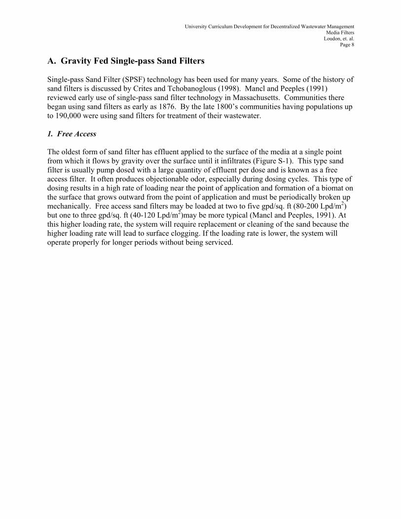
A. Gravity Fed Single-pass Sand Filters Single-pass Sand Filter (SPSF) technology has been used for many years. Some of the history of sand filters is discussed by Crites and Tchobanoglous (1998). Mancl and Peeples (1991) reviewed early use of single-pass sand filter technology in Massachusetts. Communities there began using sand filters as early as 1876. By the late 1800’s communities having populations up to 190,000 were using sand filters for treatment of their wastewater. 1. Free Access The oldest form of sand filter has effluent applied to the surface of the media at a single point from which it flows by gravity over the surface until it infiltrates (Figure S-1). This type sand filter is usually pump dosed with a large quantity of effluent per dose and is known as a free access filter. It often produces objectionable odor, especially during dosing cycles. This type of dosing results in a high rate of loading near the point of application and formation of a biomat on the surface that grows outward from the point of application and must be periodically broken up mechanically. Free access sand filters may be loaded at two to five gpd/sq. ft (80-200 Lpd/m2) but one to three gpd/sq. ft (40-120 Lpd/m2)may be more typical (Mancl and Peeples, 1991). At this higher loading rate, the system will require replacement or cleaning of the sand because the higher loading rate will lead to surface clogging. If the loading rate is lower, the system will operate properly for longer periods without being serviced.

University Curriculum Development for Decentralized Wastewater Management Media Filters
Loudon, et. al. Page 9
Dose Pump
Dose Tank
Valve Box
Sand Treatment Media
Top of Container Wall
Top of Media Treatment
Drain
Splash Plate
Figure S-1. Free access sand filter with open surface. 2. Buried Gravity Flow A similar concept used for individual homes is a sand filter known as a buried sand filter. These (Figure S-2) are usually fed by gravity flow from a septic tank and are not dosed and allowed to rest between doses. They only rest between water use episodes. In a home system this may be several hours overnight and during the middle of the day on weekdays. Design hydraulic loading rates for domestic effluent are in the range of 0.6 gpd/ft2 (24 Lpd/m2) resulting in buried sand filters providing about 250 ft2 per bedroom. These systems lack the control and uniform

University Curriculum Development for Decentralized Wastewater Management Media Filters
Loudon, et. al. Page 10
application that can be achieved with pressure dosing, but they are still used for single home systems in some Midwestern states. They are not conducive to management and are more prone to clog-up and failure than pressure dosed units. Gravity distribution often leads to early failure of the sand filter due to clogging at the sand surface. The clogging mat develops due to overloading in certain areas of the filter, which then spreads over the entire surface of the filter. In addition, most of the wastewater is discharged on a very small area of sand and percolates through the sand very quickly not providing the time to adequately treat the effluent (State of Iowa, 2003) B. Pressure Dosed Single Pass Sand Filters Single-pass sand filters, and most other Media Filters, will perform best if dosed using a pressure distribution system. Test data from field monitoring of early pressure dosed sand filters is presented by Roynayne, et al, 1982. Typically the pressure distribution is in the form of a small diameter pipe, pressure distribution system so that the effluent can be uniformly applied in small, frequent doses (Figure S-3). Pressure dosed sand filters, which are hydraulically loaded within recommended design limits (Table 1), and not overloaded organically by wastewater of high strength, have functioned for very long periods of time without significant clogging at the infiltrative surface. The small diameter pipes used to apply effluent typically are imbedded in a stone layer and have discreet orifices, generally 1/8" in (3 mm) diameter, spaced 1.5-2.5 ft (45-75 cm) apart discharging against some form of orifice shield to avoid stones interfering with orifice discharge. Orifice spacing can be reduced to improve uniformity of coverage and reduce point loading, but hydraulic and organic loading recommendations per unit area specified in the table should not be exceeded. Reducing orifice spacing will result in more orifices to be supplied with effluent at the same time resulting in a higher flow rate requirement for the pump if the orifice size and pressure are maintained. The resulting increase in required pump flow rate can be overcome by dividing the distribution system into alternately dosed zones.

University Curriculum Development for Decentralized Wastewater Management Media Filters
Loudon, et. al. Page 11
Buried Sand FilterGravity Fed
2" Sand
6-12"
Washed Pea Gravel
PVC Liner
12"
24" Min ASTM C-33 Concrete Sand
Deep Observation Port
6"6"
4" Gravity Drains
Vent
Pea Gravel or Drain Rock
Drain Lines Manifolded to One Outlet
Drain Outlet
2" Sand Cushion
Observation Port
Sandy Soil 6" Min.
From Septic TankDistribution
Box
Drain Vent
Port
Port
DeepObs. Port
Vent
Figure S-2. Buried single pass sand filter, gravity fed

University Curriculum Development for Decentralized Wastewater Management Media Filters
Loudon, et. al. Page 12
Optional Lateral/Flushing Valve Connections
6"6"
2'
6"
Sweep 2 - 45°
Single Pass Sand Filter With Discharge Pump
Geo-FabricLoamy Sand or Decorative Rock
Stone (2" Over Pipe)
Filter Sand (See Specifications)
Pea Gravel
30 MIL PVC Liner
Pump Basin Sand Backfill
2" Sand Leveling Layer
PVC Lateral w/ Orifice Shields
Flushing Valve Valve Box
Liner Support (1/2" Plywood)
To Soil
Figure S-3a. Pressure dosed single pass sand filter cross-section showing a discharge pump built into the sand filter.
30 MIL PVC Liner
Orifice Shield
Pump BasinTo Pump Control Panel
Discharge Line
Flushing Valve & Enclosure
From Septic Tank
To Soil
1.5-2.5'
Top View: Single Pass Sand Filter
1/2 Orifice Space1.5-2.5'
As Required
As Required
PVC Lateral
Deep Monitoring Tube
Shallow Monitoring Tube
1/2 Lateral Space
Figure S-3b. Pressure dosed single pass sand filter plan view showing pressure distribution network and under drain.
Other pressure distribution system configurations are discussed later in the recirculating sand

University Curriculum Development for Decentralized Wastewater Management Media Filters
Loudon, et. al. Page 13
filter section. Pressure distribution systems are typically contained within a pea stone or coarse stone layer with sufficient cover over the pipe that the applied effluent does not reach the top of the stone layer. Commonly, a shallow layer, 6-8 inches (15-20 cm) deep, of sandy or loamy sand soil is added over the stone of single-pass sand filters. The soil is usually sod covered. Improved aeration of the sand media can be achieved if the sand filter is covered with decorative stone or some other porous covering material instead of the sod covered soil. The stone covering is preferred from a functional standpoint. 1. Location Deep rooting plants must be kept away from the sand filter. Sand filters must be located and placed at an elevation such that they are not subject to surface water run-on. Traffic over the sand filter must be avoided so that the surface does not become compacted. Nothing that would reduce air movement into the sand filter should be placed over the surface. 2. SPSF Media The media specification for sand used in single-pass sand filters is critical. Most single-pass units contain a single gradation of media in the treatment layer. However, in certain specialized situations, “stratified” sand layers containing different gradations of media in discrete layers may be used. The media in any sand filter must be free of fines (particles passing a number 100 sieve – a screen with 100 openings per inch). Fine sediment, if present in the media, will be congregated in specific locations and contribute to reduction of flow that may eventually result in system failure. A useful field test for determining the presence of fines in sand filter media is the jar test. In a standard quart fruit jar place 2 inches (5 cm) of the media to be tested and add water to fill the jar three-fourths full. The material is then shaken vigorously to suspend the fines, and then allowed to stand for 60 minutes to settle (Crites and Tchobanoglous, 1998, say half full of sand and let set for 30 minutes). If a perceptible layer of fines is visible on the surface of the media (greater than approximately 1/16 inch [1.5 mm]) the sand is not clean enough to be used in a single-pass sand filter. Sand media are typically defined by their effective size and uniformity coefficient. The effective size is the particle size for which 10% of the particles in the mix are smaller (d10). The uniformity coefficient (UC) is defined as the particle size for which 60% are smaller divided by d10.
UC = d60/d10 The uniformity coefficient is an index of the degree to which particles in sand are of the same size or have a range of sizes. The larger the number is, the greater the range of particle sizes. The recommended effective size (d10) for pressure dosed single pass sand filter media is 0.012-.020 in. (0.3-0.5 mm) and the uniformity coefficient (d60/d10) recommendation is 1-4. Treatment efficiency is a function of the retention time for the applied effluent within the media.
University Curriculum Development for Decentralized Wastewater Management Media Filters
Loudon, et. al. Page 14
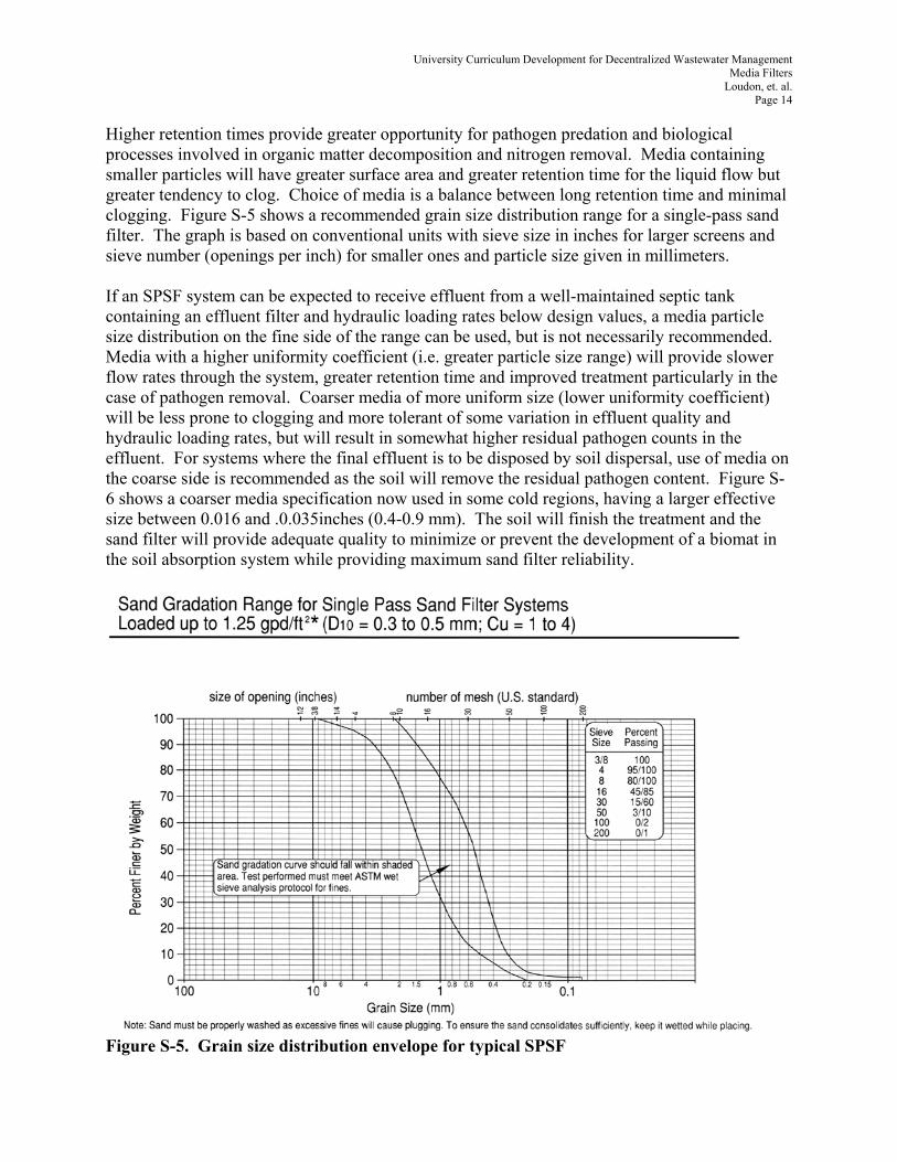
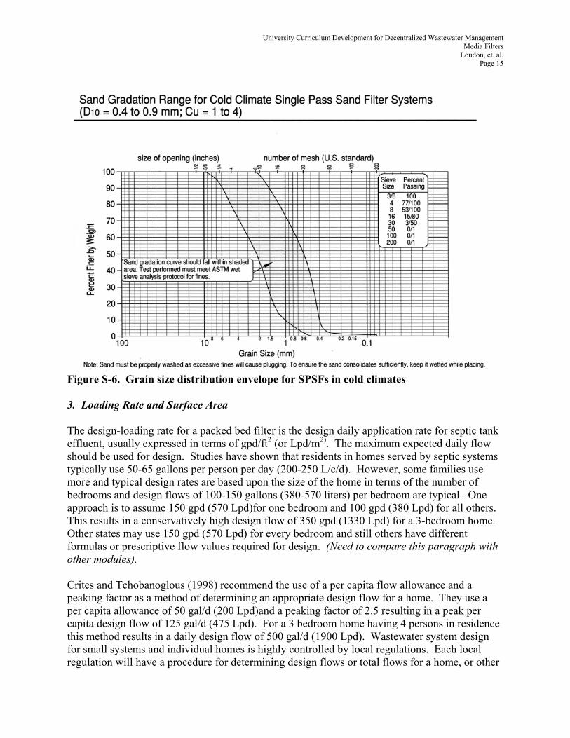
Higher retention times provide greater opportunity for pathogen predation and biological processes involved in organic matter decomposition and nitrogen removal. Media containing smaller particles will have greater surface area and greater retention time for the liquid flow but greater tendency to clog. Choice of media is a balance between long retention time and minimal clogging. Figure S-5 shows a recommended grain size distribution range for a single-pass sand filter. The graph is based on conventional units with sieve size in inches for larger screens and sieve number (openings per inch) for smaller ones and particle size given in millimeters. If an SPSF system can be expected to receive effluent from a well-maintained septic tank containing an effluent filter and hydraulic loading rates below design values, a media particle size distribution on the fine side of the range can be used, but is not necessarily recommended. Media with a higher uniformity coefficient (i.e. greater particle size range) will provide slower flow rates through the system, greater retention time and improved treatment particularly in the case of pathogen removal. Coarser media of more uniform size (lower uniformity coefficient) will be less prone to clogging and more tolerant of some variation in effluent quality and hydraulic loading rates, but will result in somewhat higher residual pathogen counts in the effluent. For systems where the final effluent is to be disposed by soil dispersal, use of media on the coarse side is recommended as the soil will remove the residual pathogen content. Figure S-6 shows a coarser media specification now used in some cold regions, having a larger effective size between 0.016 and .0.035inches (0.4-0.9 mm). The soil will finish the treatment and the sand filter will provide adequate quality to minimize or prevent the development of a biomat in the soil absorption system while providing maximum sand filter reliability.
Figure S-5. Grain size distribution envelope for typical SPSF
University Curriculum Development for Decentralized Wastewater Management Media Filters
Loudon, et. al. Page 15
Figure S-6. Grain size distribution envelope for SPSFs in cold climates 3. Loading Rate and Surface Area The design-loading rate for a packed bed filter is the design daily application rate for septic tank effluent, usually expressed in terms of gpd/ft2 (or Lpd/m2). The maximum expected daily flow should be used for design. Studies have shown that residents in homes served by septic systems typically use 50-65 gallons per person per day (200-250 L/c/d). However, some families use more and typical design rates are based upon the size of the home in terms of the number of bedrooms and design flows of 100-150 gallons (380-570 liters) per bedroom are typical. One approach is to assume 150 gpd (570 Lpd)for one bedroom and 100 gpd (380 Lpd) for all others. This results in a conservatively high design flow of 350 gpd (1330 Lpd) for a 3-bedroom home. Other states may use 150 gpd (570 Lpd) for every bedroom and still others have different formulas or prescriptive flow values required for design. (Need to compare this paragraph with other modules). Crites and Tchobanoglous (1998) recommend the use of a per capita flow allowance and a peaking factor as a method of determining an appropriate design flow for a home. They use a per capita allowance of 50 gal/d (200 Lpd)and a peaking factor of 2.5 resulting in a peak per capita design flow of 125 gal/d (475 Lpd). For a 3 bedroom home having 4 persons in residence this method results in a daily design flow of 500 gal/d (1900 Lpd). Wastewater system design for small systems and individual homes is highly controlled by local regulations. Each local regulation will have a procedure for determining design flows or total flows for a home, or other

University Curriculum Development for Decentralized Wastewater Management Media Filters
Loudon, et. al. Page 16
sources of wastewater, that must be followed. Various design hydraulic loading rates have been used for sand filters of different media and different loading configurations. Experience with modern pressure dosed sand filters has shown that design loading rates in the range of 1-1.25 gpd/ft2 (40-50 Lpd/m2) results in durable systems that provide high effluent quality (i.e. BOD and TSS less than 10 mg/L). This text recommends designing on the basis of a maximum of 1 gpd/ft2 (40 Lpd/ m2). This would result in the single-pass sand filter for a 3-bedroom home being about 350 ft2 (32.5 m2) in surface area based on a design flow of 350 gpd (1325 Lpd). If the estimated design flow is larger, the sand filter will be also, resulting in a system with a larger margin of safety. Typical effluent has BOD and TSS concentrations under 10 mg/L (often less than 5 mg/L) and usually 30-50% of the nitrogen in the influent is removed with nearly all of the remaining nitrogen in the nitrate form. Fecal Coliform counts in the final effluent are more variable, but may range from less than 50 to 104 MPN/100 ml. Typically one can expect that a single-pass sand filter will produce at least a three-log reduction. Darby et al, 1996, showed that dosing amount and frequency could influence Coliform removal. The organic loading rate for Media Filters is defined as the daily loading expressed in terms of pounds of BOD. Typical values for design loading rates of single-pass sand filters are 0.0007-0.0021 pounds BOD/ft2/day (.0034-0.010 kg/m2/day) Organic loading is calculated from BOD concentration and flow:
L = Q x BOD x 8.34 x 10⁻⁶ Where: L is organic load in lb BOD/day
Q is daily flow in gpd BOD is concentration in mg/l
Consider the situation where design flow is 350 gpd (1325 Lpd) and the expected effluent has a BOD of 130 mg/L. The organic load to be applied to a single-pass sand filter can be estimated:
L = 350 X 130 X 8.34 x 10-6 L = 0.38 lb of BOD (0.17 Kg)
If this is applied to a 350 ft2 (32.5 m2) sand filter, the unit area organic loading, La is:
La = 0.38/350 La = 0.0011 lb BOD/ft2/day (.0052 Kg/ m2/day)
As organic loading rate increases, the probability of failure increases. High strength wastes with BOD greater than domestic strength (i.e. greater than 250 mg/L) should not be applied to single-pass sand filters on a continuous basis without pretreatment. It is necessary that the designer be aware of the relationship between the design flow and the design-loading rate for Media Filters. A factor of safety must be incorporated into the design either by the choice of design flow or loading rate or both. For single home systems, the factor
University Curriculum Development for Decentralized Wastewater Management Media Filters
Loudon, et. al. Page 17
of safety must be high enough to assure that the actual loading rate will not exceed design even if high water users occupy the home. As more homes are cluster together on a system, the actual water use will approach average rates and the safety factor can be less. C. Single-pass Peat Filters Peat has been successfully used as media in Media Filters. A peat filter consists of a distribution system, the peat treatment media where the removal of organic matter and pathogens takes place, and the drain. Several companies market peat or peat fiber based single-pass Media Filters as proprietary products. Peat filters typically come prepackaged in a modular unit ready to hook up the plumbing from a pump with controls to dose the system appropriately. Some peat filters are gravity fed with a tipping bucket to distribute effluent and provide a dosing effect. The media comes in several varieties: peat moss or peat fiber in bulk, peat pellets, and peat bales. Each of these media has different characteristics as shown in Table 1. The peat media in peat filters is very carefully chosen and in some cased processed by the manufacturer. Where designers have tried to develop systems using local peat or peat from landscape firms they failed in a short period of time. Peat filters will house a wide variety of micro flora ranging from bacteria to nematodes while other filter media such as sand will host primarily bacteria. Peat, being a natural biological material, will deteriorate over time and will need to be replaced after years of use. Replacement times dependent upon the type of peat: peat moss, peat fiber or peat pellets, but life expectancy is estimated to be 8 to 15 years. Each company has proprietary information on their unit and designers must follow prescribed design criteria. Used according to recommendations, peat filters provide excellent treatment. As with sand filters, peat filters are dosed several times a day with small amounts of effluent to provide long residence time in the media as the water moves through the peat. Peat provides a large amount of surface area and at the same time a large amount of void space for air movement to put oxygen in contact with thin films of wastewater moving over the peat media structure. It is important to follow the proprietary recommendations on sizing peat filters and designing loading amounts and frequencies. Each peat module is rated for a specific daily flow. Peat filters have been shown to discharge effluent quality similar to sand filters over years of study (O’Driscoll, 1998). The treated effluent draining from peat filter containers may infiltrate into the soil by spreading into a porous matrix such as a bed of stone directly under the containers or may be diverted to a dosing tank for pumping to the soils absorption system or may be directed directly to a nearby soil absorption system.
University Curriculum Development for Decentralized Wastewater Management Media Filters
Loudon, et. al. Page 18
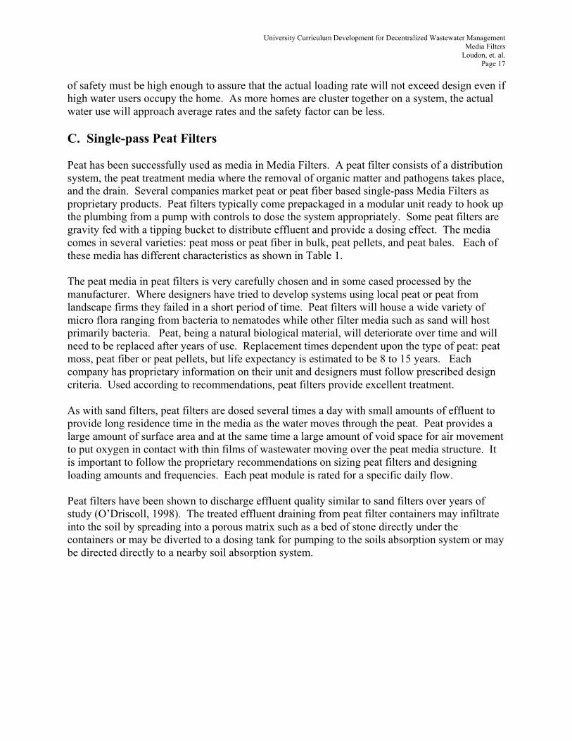
V. Recirculating Systems Public health engineers in Illinois introduced the recirculating packed bed filter concept in the 1970’s (Hines and Favreau, 1974)utilizing sand as the media. By diluting septic tank effluent with previously filtered effluent, higher application rates and smaller sand filter surface areas are possible with recirculating filters. Recirculating systems involve mixing septic tank effluent and effluent that has previously passed through the filter in a common tank known as the recirculation tank. Within this tank is a pump controlled by a timer which pumps the effluent mix over the packed bed filter at a preset frequency and for a preset duration (Figure R-1). This results in a diluted effluent being applied frequently in equal application amounts. The total daily pump run time is determined so that the total application to the filter on a daily basis is several times the daily wastewater flow coming from the septic tank. Drainage from the filter is split so that a portion goes to final dispersal (usually in the soil) and a portion is diverted into the recirculation tank. It is common to use a float based valving system in the recirculation tank to control the drainage return flow. Figures R-4 and R-5 show two types of splitter valves used to control the flow. Figure R-5 is a simple float valve that diverts all the flow coming from the packed bed filter to the soil dispersal unit or next unit in the treatment train when the recirculation tank is full. When the level in the recirculation tank drops, all the return flow is diverted to the recirculation tank to be recycled. Figure R-4 shows a splitter valve that recirculates all the filter drainage back to the recirculation tank when the float valve is open. When the float valve is closed, due to a high liquid level, a portion of the flow is still recycled while some of the flow is diverted to the soil dispersal unit.. With the ball closed and all of the overflow pipes open, 80% of the flow is recirculated and 20% is discharged. Overflow ;pipes can be capped to change this ratio.
Septic Tank Recirculation Tank Final Effluent Tank
Recirculating Media Filter
From House To Soil
Filter Drainage
Effluent Filter Float Valve in Tank Effluent PumpDosing Pump
Figure R-1. Recirculating sand filter schematic diagram.
University Curriculum Development for Decentralized Wastewater Management Media Filters
Loudon, et. al. Page 19
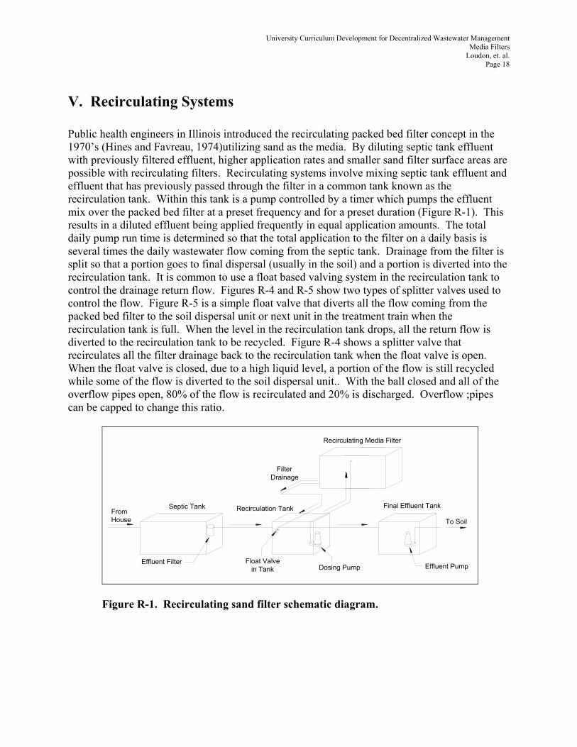
Filter Sand (refer to gradation curve)
30 MIL PVC Liner
Option: Ag. Drain w/ RSF media all the way down
See Detail A
End Cap 4" Slotted Underdrain
PVC Boot
6"-9"
24"
3/8" Pea Gravel Washed(1"-2" over laterals)
3/8" Pea Gravel
2" Sand Leveling Layer
To Recirc. Tank
PVC Lateral w/ Orifice Shields
Flushing Valve
Perimeter Support Frame (1/2" untreated plywood)
Sand
4" Boot(s)
Figure R-2. Recirculating Sand Filter cross section.
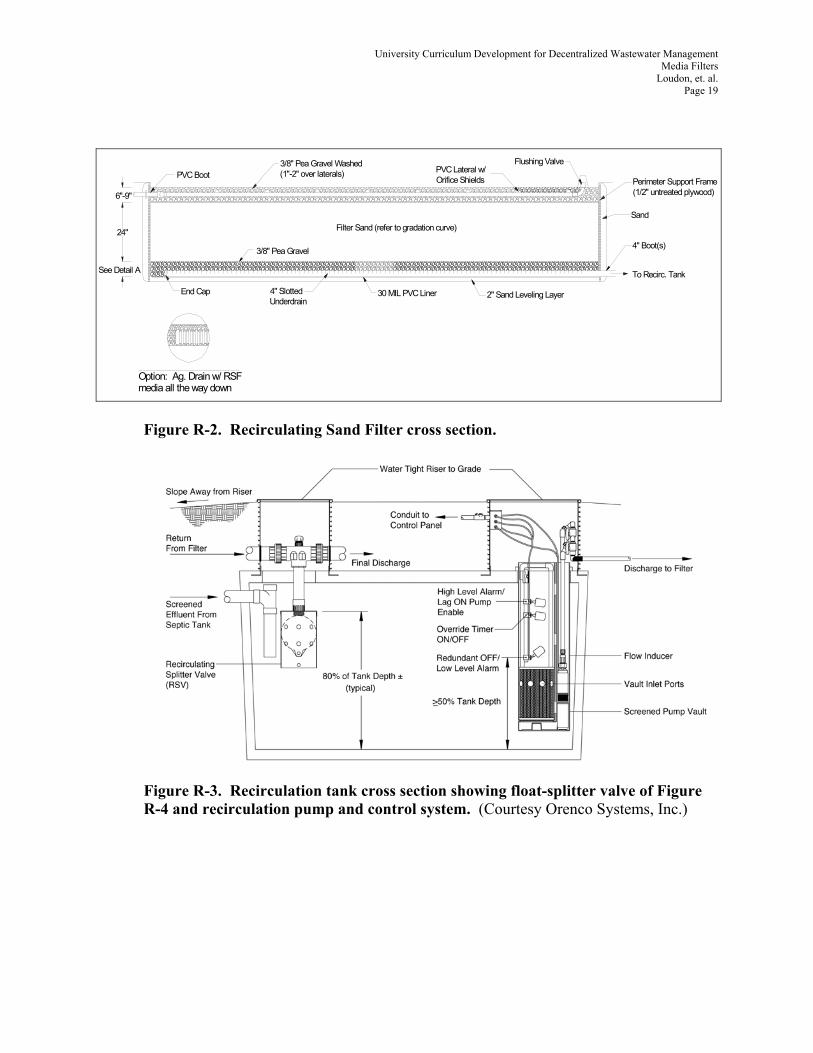
Figure R-3. Recirculation tank cross section showing float-splitter valve of Figure R-4 and recirculation pump and control system. (Courtesy Orenco Systems, Inc.)

University Curriculum Development for Decentralized Wastewater Management Media Filters
Loudon, et. al. Page 20
Figure R-4. Detail of a flow splitting float valve. (Courtesy, Orenco Systems, Inc.)

University Curriculum Development for Decentralized Wastewater Management Media Filters
Loudon, et. al. Page 21
Float Valve2" Tee
Tapered ReducerRacketball or Durable
Plastic Ball
Section of Styrofoam3" PVC
Plastic or Stainless Bar
3"x2"
Figure R-5. Simple flow splitting float valve that can be mounted in the recirculation tank.
There are several other methods of splitting and diverting flow. Figure R-6 shows a “ratio box” where an adjustable portion of the flow returns to the recirculation tank and the remainder is discharged. A disadvantage with this is that if there is no incoming flow to the system for a period of time, flow to the media filter diminishes to zero. The drainage split can also be designed into the filter by sloping a portion of the filter bottom in one direction to discharge to the soil dispersal unit or next downstream unit in the treatment train and a portion sloped to direct flow back to the recirculation tank (Figure R-7). One disadvantage of this process is that the flow split or recirculation ratio is designed into the filter, and unless a separate pump on a separate control feeds the application to the side of the filter that is designed to discharge, management cannot adjust the recirculation ratio. With separate pumps and controls for the two sides of the filter, then recirculation ratio adjustment would be possible.
2" Typ.
H
Some outlets can be blocked off
Up to 4 parts can be recirculated
Top View - Flow Splitter Basin
Discharge
Watertight Grommet
Flow Control Orifices InRemovable Standpipe
L.L.
Side View - Flow Splitter Basin
3"3"
Filter Effluent
Figure R-6. Gravity flow divider. (based on an Orenco Systems, Inc design)

University Curriculum Development for Decentralized Wastewater Management Media Filters
Loudon, et. al. Page 22
A. Recirculation Ratio (Rr)
The Recirculation Ratio (Rr) is defined as the ratio of the total recirculated flow (Qr) applied to the filter daily to the influent (forward) wastewater flow (Qi) as shown in Figure R-3a and the following expression.
Rr = Qr/Qi Qr = Rr Qi Qf = Qr + Qi = (Rr +1) Qi
where:
Rr is the recirculation ratio (can also be referred to as the recirc-blend ratio) Qr is the daily flow returning to the recirculation tank Qf is the daily flow through the filter, in gpd. Qi is the daily forward flow (i.e. daily inflow to and outflow from), in gpd Qe is the daily effluent discharge equal to the inflow in daily flow (gpd)
This concept is further illustrated in Figure R-6.
PackedBed Filter
Recirculation/Blend Tank
Qr = RrQi
Qe
Qi
Qf = (Rr+1)Qi
Figure R-6. Illustration of recirculation ratio determination. Typically Rr ranges between 3:1 and 7:1. It’s important to understand that there are both high and low practical limits to Rr. Higher ratios may be preferred to prevent odor problems, but generally should not exceed 7 or 8; ratios of 3 or 4 (with normal strength influent) are typically sufficient for controlling odors. High recirculation ratios, exceeding 7 or 8 in typical residential applications, have many adverse effects on the biology, chemistry, and life of a system. High Rr’s can deplete the base alkalinity concentration sufficiently to cause the hydrogen ion concentration to build up, driving the pH below acceptable levels. Under these conditions, the ecosystem becomes especially suited for filamentous microbes, which tend to cluster and over populate on screens and distribution pipe orifices greatly increasing the need

University Curriculum Development for Decentralized Wastewater Management Media Filters
Loudon, et. al. Page 23
for maintenance. High ratios don’t allow sufficient time for filtrate dissolved oxygen (DO) levels to deplete within the recirculation chamber. This tends to inhibit denitrification and cause greater nitrate concentrations to pass through. High ratios not only degrade effluent quality and increase maintenance demands, but also wastefully consume more energy than necessary. Excessively high Rr’s are not beneficial and would cause process degradation, regardless of the growth process (suspended or attached). The function of the Rr is as critical to process management for multiple-pass attached-growth systems as return sludge, wasted sludge, and air management are to suspended-growth processes. Proper management of the Rr assures aeration and wetting needs, but most importantly it establishes equilibrium with respect to the desired endogenous respiration rate by maintaining appropriate food-to-microorganism (F/M) ratios relative to influent hydraulic and biological loads. Depending upon the type of media in the filter, wastewater strength and effluent quality goals, recirculation ratios may vary from 2:1 to 5:1 or more. Best performance will be obtained with a recirculation ratio greater than 3:1 for systems, which are not well managed. For well-managed systems, a ratio of about 3:1 is recommended. The recirculation ratio should never exceed 8:1. Recirculation ratios greater than 3:1 may result in a system being too aerobic and an aerobic floc growing in parts of the system such as the distribution piping or effluent screens in the recirculation tank. Lower recirculation ratios will generally result in a higher percentage nitrogen removal as well. With a simple float valve in the recirculation tank, the recirculation mix will vary continuously depending upon the flow rate coming from the septic tank. A float valve with continuous discharge back to the recirculation tank helps dampen out some of the variation in recirculation mix. See Figure R-4. The average recirculation rate is determined by how the timer controlling the pump in the recirculation tank that feeds the sand filter is set. If a 4:1 recirculation rate is desired then the pump is set to run enough minutes per day to pump 5 times the daily forward flow to the media filter. On the average one-fifth of this will be flow from the septic tank and four-fifths will be return flow from the filter.. The desired flow quantity delivered to the filter per dose and the number of doses per day will vary depending upon the type filter media being used.

University Curriculum Development for Decentralized Wastewater Management Media Filters
Loudon, et. al. Page 24
Septic TankSand Filter Dosing Tank Final Effluent Tank
Sand Filter
From House To Soil
Effluent Filter Sand Filter Dosing PumpOn Timer
Effluent Pump(Float Controlled)
Denitrifying Sand Filter
Return
Filter Drainage
Recirc Tank
Figure R-7. Schematic of a recirculating sand filter with dual slope bottom to provide the recirculation ratio.
Recirculating systems generally involve pressure distribution to provide uniformity of application over the media. As discussed under the single-pass systems, various application technologies are possible. The goal is to provide uniform distribution while providing flexibility in adjustment of dose volume and dose frequency. B. Recirculating sand filters Recirculating sand filters (RSF)are used for systems as small as individual home systems up through systems for small communities. Maximum practical size depends somewhat on the relative cost of land versus the long-term cost of energy and management for more intensive systems that occupy a smaller footprint. . C. Recirculating Gravel Filters Recirculating gravel filters (RGF), filters containing larger media, in the gravel size range of 3-5 mm or larger, are sometimes used for systems where waste strength may be slightly higher or where the reliability of maintenance is uncertain and effluent quality is not on utmost importance. Filters using larger media are somewhat more prone to sloughing solids off the media and generally produce a poorer quality effluent in terms of BOD and TSS in the effluent. However, these units will produce a high quality secondary effluent with BOD and TSS typically in the range of 10 – 20 mg/L. D. Recirculation tank The recommended recirculation (or blend) tank volume for RSFs is equal to the average daily design flow to be treated by the system. This provides adequate volume and hydraulic retention time for blending the flow as input from the primary treatment facility varies throughout the day.

University Curriculum Development for Decentralized Wastewater Management Media Filters
Loudon, et. al. Page 25
This size could be reduced if a very uniform incoming flow rate is expected throughout the day but this would be an unusual situation. In such case, hydraulic retention time and surge capacity should be carefully evaluated. E. RSF media The media recommended for recirculating sand filters is very coarse sand or fine gravel. The exact specification depends on the degree of treatment desired. The state of Oregon has media research based specifications that have met the test of time and are accepted by other states as well (Oregon Rules (ORS 340-71). They state that where carbonaceous BOD5 removal must be at least 85 percent, based upon the raw sewage concentration applied to the septic tank, and nitrification of wastewater is necessary, a filter media of the following fine gravel is required: 3 feet (0.9 m) of very fine washed gravel, 100 percent passing a 3/8" (6.4 mm) sieve with an Effective Size between 3 and 5 millimeters, and a Uniformity Coefficient of 2 or less. Washed shall mean that negligible fines (less than 1.0%) pass the No. 100 sieve. Where additional removal of BOD5 and denitrification is intended or required, a treatment media of the following coarse sand may be approved: 2 feet of very coarse washed sand, 100 percent passing a 3/8" (6.4 mm) sieve with an Effective Size between 1.5 and 2.5 millimeters, and an Uniformity Coefficient of 2 or less. Washed shall mean that negligible fines (less than 4.0%) pass the No. 100 sieve. See Figure R-8.
Figure R-8. Grain size distribution curve envelop for recirculating sand filter media.

University Curriculum Development for Decentralized Wastewater Management Media Filters
Loudon, et. al. Page 26
It is important that the content of fines (materials passing a number 100 sieve) be as low as possible, preferably less than 1% even though the specification above allows more. It is also important that the media be handled so as not to introduce any fines in the construction process and that the area immediately surrounding the filter site be protected against wind erosion so that fines are not blown onto the filter. The surface of an RSF is an exposed stone surface so any blown in sediment deposited on the surface will be moved down to the infiltrative surface by rain and will contribute to clogging. F. Filter drain Adequate drainage must be provided so that water can move freely from the bottom of the filter. Typical drains are 4" diameter slotted pipe. Either material manufactured by cutting slots in PVC or slotted, corrugated polyethylene drainage pipe may be used. Drainpipe should never be surrounded by a geofabric or filter fabric. This material will clog rapidly and prevent flow from entering the drain. An “envelope” of large pea stone or coarser drain stone may be placed around the drain. This is necessary if drainpipe with large slots is used; follow manufacturer’s recommendations. If agricultural drainage tubing with smaller slots is used, neither a gravel envelope nor a coarse bottom layer is necessary as long as the media meet the normal RSF specification. A ball valve on the drain outlet is recommended so that the drain can be closed and the sand filter cell used as a temporary holding cell if it is necessary to lower the level of the water in the recirculation tank to work on components in the tank such as the recirculation valve. A sampling sump at the drain outlet is useful for obtaining samples to judge filter performance. The drain outlet must not be submerged, so that air can freely move into and up through the drain to assist the treatment media aeration process. Recommended RSF treatment media depth is 24"-30" (60-75 cm). If only 24" (60 cm) of treatment media depth is used a 6" (15 cm) layer of pea stone or coarse drain rock should be placed in the bottom of the filter to facilitate lateral drainage and maintain at least 24" (60 cm) of unsaturated treatment media throughout the filter. If the same size media is continued all the way to the bottom liner, there will be slightly more capillary rise from the saturated zone in the bottom up into the media than if there is a distinct media gradation discontinuity as provided by a courser layer in the bottom of the filter. Thus, the recommendation of 6” (15 cm) more media is appropriate. An alternative to pipe drains is to utilize drainfield chambers or some other method of forming a cavity in the bottom of the RSF, and utilize the volume in this cavity as the recirculation and mixing zone. This eliminates the need for a recirculation tank. One or more small pump chambers are used outside the filter to accept filter drainage and pump it back over the filter or to final dispersal. Usually a split bottom filter configuration such as shown in Figure R- 7 is used with the incoming effluent coming in at one end of the other larger side and the drainage from that side going to a pump chamber that recycles over the entire filter. The smaller end drains to a second pump chamber that pumps to final dispersal. In this configuration the septic tank effluent should be discharged into one corner or one side of the cavity in the bottom of the filter cell and
University Curriculum Development for Decentralized Wastewater Management Media Filters
Loudon, et. al. Page 27
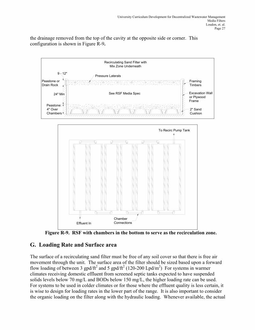
the drainage removed from the top of the cavity at the opposite side or corner. This configuration is shown in Figure R-9.
Peastone: 4" Over Chambers
24" Min
9 - 12"
See RSF Media Spec
Framing Timbers
Excavation Wall or Plywood Frame
2" Sand Cushion
Peastone or Drain Rock
Pressure Laterals
Recirculating Sand Filter with Mix Zone Underneath
Effluent In
To Recirc Pump Tank
Chamber Connections
Figure R-9. RSF with chambers in the bottom to serve as the recirculation zone. G. Loading Rate and Surface area The surface of a recirculating sand filter must be free of any soil cover so that there is free air movement through the unit. The surface area of the filter should be sized based upon a forward flow loading of between 3 gpd/ft2 and 5 gpd/ft2 (120-200 Lpd/m2) For systems in warmer climates receiving domestic effluent from screened septic tanks expected to have suspended solids levels below 70 mg/L and BODs below 150 mg/L, the higher loading rate can be used. For systems to be used in colder climates or for those where the effluent quality is less certain, it is wise to design for loading rates in the lower part of the range. It is also important to consider the organic loading on the filter along with the hydraulic loading. Whenever available, the actual
University Curriculum Development for Decentralized Wastewater Management Media Filters
Loudon, et. al. Page 28
effluent characteristics should be used for designing the filter. When effluent strength exceeds typical domestic effluent quality, the filter must be designed on the basis of the organic load, typically expressed in terms of lb BOD/ft2/day (Kg BOD/m2/day). Insufficient research has been done to define design organic loading rates well. Typical values for RSF’s range from 0.002 to 0.008 lbs BOD/ft2/day (.01-.04 Kg/m2/day). High recirculation rates are recommended as the organic loading approaches the upper portion of this range. Maintenance personnel should be alerted to watch for the development of media clogging where the higher organic loading rates are anticipated. H. Distribution System Design The most common distribution system design for RSFs is small diameter pipe with 1/8" (3mm) orifices spaced approximately 2 feet on center and 2 feet (60 cm) between distribution pipes. This configuration balances reasonable distribution against required flow quantities and therefore pump sizes. Some designers have successfully used orifice spacing as low as 15 – 18” (38-46 cm) to spread the applied effluent more uniformly over the surface area of the filter. It is recommended that a minimum residual head at the far end of the most distal lateral be maintained at 5 feet (150 cm) of water pressure. There should be no more than a 10% differential in flow between any two orifices in the system (i.e., between distal orifices and those nearest the pump). The use of turbine pumps with steep characteristic curves is recommended. A steep curve means that as orifices begin to clog and the flow demanded from the pump drops slightly, the pressure increases rapidly. This results in the system being somewhat self-cleaning as higher pressures will help keep orifices open. Turbine pumps with steep curves have low maximum flow capabilities in the lower horsepower range. In order to keep pump sizes in the half horse power range, it is recommended that the distribution system be divided into zones which require no more than 50 gallons per minute each. An automatic hydraulically-operated sequencing valve (Figure R-10) can be utilized to sequentially feed the distribution zones of the system. (See the hydraulics module for details on pressure distribution system design).

University Curriculum Development for Decentralized Wastewater Management Media Filters
Loudon, et. al. Page 29
1 Valve top 2 Valve Body3 Inlet 4 Vacuum
breaker port
5 Valve Bottom
6 Outlets
Figure R-10. Hydraulically operated zone sequencing valve (K-Rain, Inc.) Low-pressure pipe with orifices may be mounted directly in distribution stone (though not recommended), may be in stone with orifice shields over each individual orifice, may be inserted in a larger pipe sleeve that is perforated to release the water into surrounding stone or the pipe may be mounted in chambers with the jet from each orifice impinging on the chamber surface to break into droplets and provide distribution (Figure R-11a). In some media filters, such as open cell foam filters, spray nozzles are utilized to distribute effluent more uniformly over the surface of the media. The nozzles typically used are helical spiral non-clog nozzles mounted with the spray directed downward onto the media. These nozzles can also be utilized in chambers with the plumbing mounted in the top of the chamber and the nozzles directed downward to provide uniform distribution of effluent over the base of the chamber (Figure R-11b). They are also used in applications where the entire packed bed filter is housed in a container specially built for the unit.

University Curriculum Development for Decentralized Wastewater Management Media Filters
Loudon, et. al. Page 30
2" Over Chambers
24" MinRSF Treatment Media
Sand Filter w/ Upward Directed Orifices in a Chamber
Pea Gravel
Pea Gravel
PVC Liner
Figure R-11a. Effluent distribution by upward directed orifices in chambers.
2" Over Chambers
24" MinRSF Treatment Media
Sand Filter w/ Spiral Nozzles in a Chamber
Pea Gravel
Pea Gravel
Figure R-11b. Effluent distribution by non-clog spiral nozzles in chambers. Orifice configurations provide application at discreet points rather than uniformly distributed over the surface of the media. In the case of single-pass sand filters and the recirculating gravel filters the discreet point application results in only a portion of the media receiving effluent unless the media starts to clog. More research is needed to understand the pros and cons of closer versus wider orifice spacing. With only a portion of the media utilized, the surrounding media always contains air with higher oxygen concentrations, which can diffuse into the zone of treatment to provide the necessary oxygen for the organisms. However, with good ventilation this may not be needed. Orifice spacing of 24" x 24" (60 x 60 cm) on single-pass sand filters and recirculating gravel filters have been common but spacing as low as 9" x 9" (22 x 22 cm) have been utilized (Piluk and Peters, 1994). Regardless of orifice spacing, recommended loading rates per unit area should not be exceeded or extensive maintenance problems may result.

University Curriculum Development for Decentralized Wastewater Management Media Filters
Loudon, et. al. Page 31
I. Pumping Systems for RSF’s The pumps feeding recirculating sand filters are always timer controlled. Timers should be set so that the dose volume from each orifice does not exceed one gallon per orifice per dose cycle. The flow rate from a 1/8" (3mm) orifice subjected to 5 ft (150 cm) of head is 0.43 gpm (1.6 Lpm). Therefore the maximum allowable pump run time per dose at 5 ft (150 cm) of head is less than 3 minutes unless there are very long pipe runs that take a long time to fill and come to pressure. Pumps can be cycled frequently but the number of pump cycles per day should not exceed about 300 for long pump life. Some pump manufacturers may have other recommendations. Always check and follow manufacturer’s recommendations for their specific pumps. If low head effluent pumps are used and orifices begin to clog, the result may be that the pump does not move enough effluent out of the tank and a high water alarm condition may result, signaling to the operator that something is wrong. An alternative method of distribution on a packed bed filter is to use drip irrigation tubing with its specially manufactured emitters. Drip emitters are capable of discharging very low rates of flow, literally drips, as the name implies. With drip tubing, the space between the points of application can be minimized and the application rate to the filter minimized as well. Use of drip tubing requires special filtration and regular flushing of lines, but these processes can be automated. The reader is referred to the module on drip distribution for more detail. J. Large Recirculating Sand Filters Large recirculating sand filters should be designed in cells so that if maintenance is necessary one cell can be shut down and the others used while cell maintenance is accomplished. The system should be designed with maintenance in mind. Every cell should have observation ports at one or more locations that extend from the surface of the cover media to the surface of the treatment media so that it is easy to monitor for clogging and ponding at the infiltrative surface. Observation ports that extend to the bottom of the filter should also be provided so that if there is a clog in or around the drain that begins to cause an abnormal level of ponding in the bottom of the cell, it can be detected easily and early. Flooding the filter and forcing air into the bottom to raise the dissolved oxygen level in the cell and stimulate aerobic organisms to digest the organic clogging materials that may have formed can remedy clogging. This necessitates a drainage system that can effectively serve as an air distribution system when the cell is flooded. In anything other than individual home systems, it is a good idea to provide redundancy if less than four pumps are used in the system.

University Curriculum Development for Decentralized Wastewater Management Media Filters
Loudon, et. al. Page 32
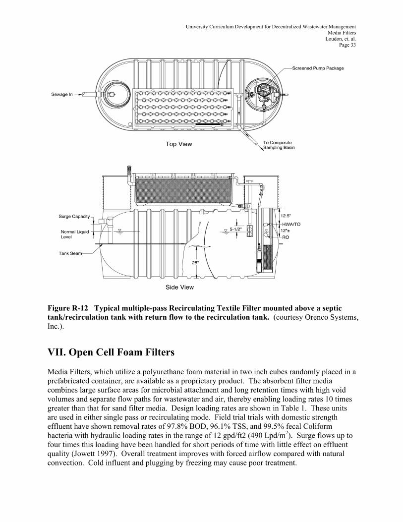
VI. Textile Filters The use of geosynthetic fabrics, commonly called geotextiles, as a media in Media Filters has been a subject of considerable research and development over the past decade. Geofabrics offer characteristics that are consistent with the media characteristics desired in a packed bed filter, namely, they provide both large surface area and large void volume per unit bulk volume of material while maintaining a high water holding capacity. These materials have been used in two configurations: (1) small squares about 2” by 2” (5 cm x 5 cm) of ¼ - 3/8 in (6-9 mm) thick fabric randomly packed in a container with capillary breaks between 4-6 in (10-15 cm) thick layers and (2) hanging curtains of fabric about ½ in (12 mm) thick. The hanging curtains have become the most widely accepted configuration. In residential applications, the filter typically is placed over or next to the septic tank or a recirculation tank. The filter drainage returns to the recirculation tank if BOD and TSS removal is the main goal. If maximum nitrogen removal is desired, the drainage is directed to the inlet end of the septic tank. Filter drainage is controlled by the liquid level in the tank and at any given moment it is either all going into the tank or all going on to the next unit in the treatment system. Figure R-12 is an illustration of this type packed bed filter set up in recirculating mode with recirculation back to a septic tank. Vertical sections of fabric about 2 ft long are hung side by side so that they are touching. Wastewater is applied over the top of the fabric in small, uniformly distributed doses several times per hour. This keeps the fabric wet and provides maximum residence time for the water within the fabric. Table 1 shows the characteristics of the fabric filters in comparison with other packed bed filter media. The textile filter operates in the recirculating mode, much like a recirculating sand or gravel filter. Due to the increased surface area of the media, loading rates can be much higher (5-15 times) than recirculating sand filters and thus filter size can be smaller for a given wastewater flow. Aerobic conditions are maintained due to the large volume of pore space through which air can flow even while the material is wetted to its drained upper limit of moisture content. A biofilm develops on the upper surface of the media. Organic matter, measured in terms of BOD and TSS is removed efficiently. Ammonium nitrogen is nitrified to nitrate by the same type biological processes that occur in sand filters. Nitrogen removal is enhanced by circulating the filtrate back to the carbon rich septic tank to increase denitrification. If necessary the biomat that builds on the top of the textile configuration can be periodically removed with a hose or individual hanging curtains can be removed for more complete cleaning. As with all Media Filters, periodic maintenance by a trained service provider is critical to maintaining high quality effluent from the filter.
University Curriculum Development for Decentralized Wastewater Management Media Filters
Loudon, et. al. Page 33
Figure R-12 Typical multiple-pass Recirculating Textile Filter mounted above a septic tank/recirculation tank with return flow to the recirculation tank. (courtesy Orenco Systems, Inc.).
VII. Open Cell Foam Filters Media Filters, which utilize a polyurethane foam material in two inch cubes randomly placed in a prefabricated container, are available as a proprietary product. The absorbent filter media combines large surface areas for microbial attachment and long retention times with high void volumes and separate flow paths for wastewater and air, thereby enabling loading rates 10 times greater than that for sand filter media. Design loading rates are shown in Table 1. These units are used in either single pass or recirculating mode. Field trial trials with domestic strength effluent have shown removal rates of 97.8% BOD, 96.1% TSS, and 99.5% fecal Coliform bacteria with hydraulic loading rates in the range of 12 gpd/ft2 (490 Lpd/m2). Surge flows up to four times this loading have been handled for short periods of time with little effect on effluent quality (Jowett 1997). Overall treatment improves with forced airflow compared with natural convection. Cold influent and plugging by freezing may cause poor treatment.

University Curriculum Development for Decentralized Wastewater Management Media Filters
Loudon, et. al. Page 34
Septic tank effluent or blended effluent from a recirculation tank is applied to foam filters in small doses of 0.1-1 gal/ft2(4-41 L/m2) per dose using helical spray nozzles for uniform distribution. Manufacturers recommendations vary, but usually dosing is controlled by a timer to provide uniform application throughout most of a day regardless of water use patterns within the facilities being served. Open cell foam filters are more easily maintained than sand based Media Filters. Any clogging due to biomat development is usually within the top few layers of foam cubes so these can be removed and replaced or cleaned and returned. Being in a container and having much less surface area contributes to easier maintenance as well. The open cell foam filter was originally developed to treat domestic septic tank effluent, but it has also been used effectively for municipal sewage, landfill leachate, and other wastewaters. (Jowett and McMasters, 1994) VII. Controls Control systems for pumps and dosing are critical to the operation of Media Filters. Details on control systems are provided in a companion module on Instrumentation and Controls. Issues related to selection and adjustment of controls for Media Filters will be discussed here. As indicated earlier, all Media Filters should be pressure dosed to assure uniform distribution of effluent. This can be done either by using pump systems or, in some cases by using siphons for dosing. Pump systems may be demand controlled or timer controlled. Level sensors set to provide a predesigned dose volume control demand systems. With demand systems, the filter receives a dose of effluent whenever a sufficient quantity of water has been used at the source to generate one dose. The filter is therefore dosed frequently during periods of high water use and does not receive doses if there is no water being used at the source. Therefore, demand-dosed systems suffer from the tendency to be dosed too frequently at times while allowed to be unfed for fairly long periods of time when no wastewater is being generated, such as overnight. It is also difficult to control the dose volume with demand systems because dose volume is a function of tank cross-section and the ability to adjust on/off level of floats, or other level control devices for a small enough change in tank level during a pump cycle is limited. Research has shown (Emerick, 1997, et. al.) that treatment is enhanced with small, frequent doses. Timer control pumps provide the ability to apply small, frequent doses so timer control systems are highly recommended. The timers themselves can be float controlled so that when the water level in the supply tank reaches a certain minimum, a level sensor turns the timer off and the timer remains off until the water level starts to increase. Then the timer is reactivated and operates to provide dosing until the minimum pool level is again reached. Timers can be overridden by a high level sensor such that if the level in the tank reaches a predetermined high level, the system can become level controlled until the level again is down to the top of the range in which the timer operates. Some controls can also increase the frequency of dosing when the high level is reached rather than reverting to demand dosing. An alarm can be activated when

University Curriculum Development for Decentralized Wastewater Management Media Filters
Loudon, et. al. Page 35
this happens or a separate level sensor can be set just above the timer override level so that an alarm is only actuated if the timer override does not keep up with the rate of wastewater inflow. Figure C-1 shows a pump in a recirculation tank with floats to turn the timer on and off and, if the level in the tank reaches a preset high level, turn on a second pump, or if there is only one pump, run the pump on the float until the level is reduced to the normal range. The reader is encouraged to consult the module on Instrumentation and Controls for more information.
Figure C-1. Pump vault in a recirculation tank showing float controls to manage the timer, alarm a low level or high level, and turn on a second pump if the high alarm is reached. A. Level Sensors Description of various level sensors is included in the Instrumentation and Controls module. The most common sensors used with packed bed filter control systems are floats. Some floats are mechanical while others contained mercury switches. Due to environmental concerns with mercury, manufacturers are moving away from the use of mercury switch floats. Level sensors should be mounted on a specially designed mounting system separate from the pump and discharge pipe. This simplifies service and sensors mounted on the discharge pipe of a pump are subject to vibration and may work loose and move. Options are shown in the Instrumentation and Controls module. Sensor mounting systems allow for the level sensors to be easily removed as a group and adjusted outside the tank without disturbing the pump. Also, the pump can be pulled for service without disturbing the adjustment of the level sensors. All pump chambers should be equipped with a riser to grade and a secure lid. Sufficient cord for each level sensor and the pump should be retained in the riser so that pumps and sensors can be easily removed from the tank for service without disconnecting anything. This cord slack should be neatly coiled and tied off in a convenient location in the riser. It is sometimes convenient to have an electrical junction box in the riser over the pump tank to connect the manufacturer

University Curriculum Development for Decentralized Wastewater Management Media Filters
Loudon, et. al. Page 36
provided cords on pumps and level sensors to wires leading to the control box. A junction box (classification NEMA 4X) in the riser is permissible for pumping systems serving no more than five dwellings (National Fire Protection Association Standard 820). Such facilities are unclassified by NFPA 820 as they are expected to vent through the plumbing system for the dwellings. Systems that serve more than five dwellings are not automatically covered by this unclassified designation. Wire connections in a junction box mounted in a riser are in a very moist and corrosive environment. Wire splices should be done using sealed, waterproof connections and waterproof cord grips must be used where the cords penetrate the junction box. A better solution may be to avoid the junction box altogether by specifying pumps and controls with sufficient cord to be run all the way to the control box location without any splice. B. Determining Timer Settings Pump timers need to be set so that the total flow anticipated can be pumped to the packed bed filter on a 24-hour basis. To allow for peak periods of use, it is generally recommended that timers be set so that the quantity of effluent generated in the typical 24-hour day can be pumped to the filter in about 18 hours of timer activated pump operation. In the case of single pass systems, this means that under normal flow conditions, the pump will be shut down for several hours every night. However, if the incoming flow is greater than the anticipated average daily flow, the pumps will operate more hours. If the flow exceeds the average flow for which the system is adjusted by more than 33% (6/18 x 100%), a high water alarm will be experienced. In recirculating systems, the recirc-pump(s) do not shut down ever. When the nightly inflows drop off, the water level activated recirc-splitter valve (RSV) opens and returns all the filtrate to the recirc-tank so no filtrate is discharged during the low flow periods. The packed bed filter, though, is continually dosed to keep the dissolved oxygen level from depleting completely in the recirc-tank during low inflow periods, which would cause anaerobic gas products to generate and cause periodic odors when the recirc-pump(s) come back on. This means that there is adequate surge volume designed into the recirc-tank to accommodate peak daily usage while the recirc-valve opens during low flow periods returning all the filtrate to the recirc-tank. Controls can be included with a feature that will provide a high level timer override that increases the dose frequency in the event of extreme high flow occurrences like broken or stuck toilet floats that may add more than a 1000 gallons a day to the inflow volume. Controls can also be set up to alert the service provider when the flows exceed normal peak limits. The dosing frequency (DF) is typically reported as the number of doses or dosing events/day, but more specifically represents the time span between doses (the time measure is generally in minutes) or, in control terminology, the cycle-time (CT). There are two components to the cycle time: the “ON” (dosing) time and the “OFF” (resting) time as shown in the following expression:
CT = DF = Td + Tr And also , DF = 1440* min per day/nd Where nd is the number of doses per day to the filter nd = Qf /Tdqf

University Curriculum Development for Decentralized Wastewater Management Media Filters
Loudon, et. al. Page 37
nd = (Rr + 1)Qi /Tdqd
DF = 1440Tdqd / (Rr + 1)Qi And from Figure R-5 Rr = (Qf/ Qi) - 1
where: CT is the dose cycle time in minutes DF is the dose frequency time in minutes nd is the number of doses per day Tr is the rest time in minutes (“off”) Td is the dose time in minutes (“on”) qd is the dosing flow rate to the filter, gpm. Qi is the daily inflow (or forward flow), gpd Qf is the daily filter hydraulic load, gpd Rr is the recirculation(recirc-blend) ratio
The dosing frequency is related to the Rr as well as particular features of the media, such as its texture, void ratio, water-holding capacity etc. Considerable academic work has been done to establish relative dosing frequencies for various media. It’s well established that small frequent doses improve filter performance. Increasing the dosing frequency (number of occurrences over a given time period) reduces the volume of wastewater applied per dose and increases Coliform removal (Darby et al, 1996). Example: Determine the recirculation ratio for an RSF receiving 500 gpd if the dose flow rate to the filter, qd, is 30 gpm, the dose frequency is 10 minutes, and the dose time, Td, is 30 seconds.
DF = Td + Tr Td = 0.5 min Tr = 10 min – 0.5 min = 9.5 minutes Qf= nd Td qd = (1440 / DF) Td qd Qf= 1440 (0.5 min) (30 gpm) / 10 min = 2160 gpd
and:
Rr = (Qf/Qi) - 1 = (2160/500) - 1 = 3.32
Or … if the Rr is set at 3 and the dose time is 30 seconds:
Tr = [1440 Td qd /(Rr + 1)Qi] - Td Tr = [1440 (0.5) (30) / (3 + 1) (500)] - 0.5 Tr = 10.3 minutes (Rest or “OFF” time) And: CT = 10.3 + 0.5 = 10.8 minute cycle time (or Dose Frequency every 10.8 minutes)
University Curriculum Development for Decentralized Wastewater Management Media Filters
Loudon, et. al. Page 38
Event counters and run time meters on the pump are very helpful in documenting the operation of the system. It can be utilized to determine the total quantity of flow handled by the pump over a period of time and can be used to determine whether the pump frequently operates in the demand mode as compared to being operated mostly by the timer. For more details refer to the module on Instrumentation and Controls. Examples _________ ______________ show how this data from the event counters and run time meters can be utilized. IX. Pump Selection Two basic types of submersible pumps are commonly utilized to feed Media Filters. These are submersible centrifugal effluent pumps and submersible centrifugal turbine (high head) pumps. Self-priming centrifugal suction pumps mounted outside the tank can also be used, but these are much less common. [NEED TO ADD FIGURES TO SHOW DIFFERENT TYPES OF PUMPS. ARE THESE AVAILABLE FROM OTHER MODULES??]. Effluent pumps are low-pressure pumps with capacity for handling some solids. Solids handling is not necessarily a desirable feature of pumps feeding Media Filters, but the general flow and head capabilities of effluent pumps and their wide availability and dependability makes them a common choice. All but the smallest suspended solids should be removed in the septic tank and/or filtered out using effluent screens (< 1/8 in openings) prior to the pump intake. Turbine pumps have capacity to generate higher pressures but lower flows than effluent pumps. Turbine pumps are desirable for feeding pressure distribution systems on Media Filters because of their steep discharge curves that result in rapid increases in pressure as the flow drops by small amounts. This helps keep orifices open and the system functioning with complete, uniform distribution. Where effluent pumps are utilized, greater care may be necessary in monitoring and maintaining the distribution system to assure that the entire system is functioning all the time. Both types of pumps have long service lives and are designed for the effluent environment. It is recommended that pumps be continuously submerged to avoid potential corrosion problems. It is the designer’s responsibility to assure that the proper pump is chosen for the specific application. (Example problems showing pump selection processes will be added.) X. System Monitoring A. Monitoring Tubes It is important that Media Filters be set up so that maintenance personnel can easily monitor their performance. In the case of proprietary media filters, manufacturers provide monitoring recommendations. In the case of both single-pass and recirculating sand filters, it is recommended that monitoring tubes be placed to the bottom of the stone around the distribution pipe, bottoming at the infiltrative surface of the treatment media. These should be placed in strategic locations so that it will be possible to observe any ponding that may begin to occur on the infiltrative surface. Monitoring tubes should also be installed all the way to the bottom of the filter, bottoming at the surface of the liner, to determine if the level of ponding in the base of the

University Curriculum Development for Decentralized Wastewater Management Media Filters
Loudon, et. al. Page 39
filter is normal. Monitoring tubes located at the maximum distance from underlying drains are recommended for this purpose. The monitoring tube is a 3" or 4" pipe, perforated in the bottom few inches, and placed during construction. Support options for monitoring tubes are shown in Figure M-1. Monitoring tubes should be capped with an easily removable cover. The use of valve boxes over the top of monitoring tubes is recommended. If other forms of a cover are used such as slip caps, it is necessary to anchor the bottom of the monitoring tube when it is installed with a flange, tee, or rods through the pipe to render it secure so that it is not pulled out when trying to remove the cover. Valve box covers are not directly connected to the monitoring pipe and do not present this problem.
Figure M-1. Options for mounting observation tubes. B. Remote Monitoring Equipment and technology are available for providing remote monitoring of water levels, pressures, flows, and pump-run events. Data can be sensed and stored on a local data logger for periodic downloading to a monitoring computer. This type of system can be programmed to recognize parameters that are out of range and to alert maintenance personnel. Maintenance personnel can troubleshoot the system from a remote computer and often determine and fix a problem without visiting the site. If the problem is occurring because a timer is not correctly adjusted to accommodate the flows occurring, it can be reset from the remote location. The sophistication and cost of remote monitoring make it an attractive alternative for many systems. Designs for commercial systems, community or cluster systems, and remote or sparse systems

University Curriculum Development for Decentralized Wastewater Management Media Filters
Loudon, et. al. Page 40
where access for maintenance is time consuming and expensive should incorporate remote monitoring. Designers should continue to track the development of remote monitoring technologies and incorporate it where feasible. C. Monitoring Routine All Media Filters require monitoring and maintenance. For proprietary products the manufacturer provides a maintenance routine. In the case of sand filters without remote monitoring it is recommended that a complete monitoring visit be made in the first few weeks of operation with a second visit about six months later. Monitoring visits must be at least annually thereafter. Twice a year is highly recommended until the maintenance provider is comfortable that use patterns and filter performance warrant reducing the frequency to annually. Commercial systems should have monitoring visits at least twice per year. A typical maintenance visit should include: 1. Check sludge and scum levels in the septic tank to assure adequate clear
space. 2. Check septic tank effluent screen and/or pump vault screen, or in-line
filter, and clean if necessary. 3. Flush packed bed filter distribution laterals. 4. Check pressure at the distal end of the lateral and compare with design
recommendations or pressure monitored at the last visit. If pressure has increased since the last measurement, it may be necessary to use a bottlebrush, pressure jet, or other orifice or nozzle cleaning process.
5. Note readings on pump run-time meter and event counter and compare with previous readings.
6. Check pump voltage (off and while pumping) and amp draw while pumping.
7. Check pump control floats for proper operation and proper elevation adjustment.
8. Check for ponding at the media infiltrative surface and the bottom of the filter through observation tubes.
9. Pull and observe the final effluent in a clear sample bottle checking for clarity and odor.
10. Check for wetness around the drainfield and observe ponding in observation tubes.
D. Monitoring User Inputs At the time of performing a monitoring operation, it is always a good idea to visit with the owner or operator of the system to determine whether anything has changed in terms of water inputs or problems noted with the operation of the system. Remind the owner of cautions in use of the system including conservatism in water use. Certain inputs can influence the operation of the system including strong drugs (chemotherapy or dialysis in particular), chronic use of drain cleaners, input of water softener backwash to the system, and improper inputs such as paint

University Curriculum Development for Decentralized Wastewater Management Media Filters
Loudon, et. al. Page 41
thinner, antifreeze, etc. The owner should be cautioned against discharge of such substances to the system. In some cases, lack of alkalinity in the source water may influence the ability of the system to remove nitrogen. A complete discussion of nitrogen removal process is discussed in the Nitrogen Module. XI. Soil Dispersal of Packed bed filter Effluent High quality effluent such as that from a well maintained packed bed filter is not likely to develop much, if any, biomat in soil absorption systems and can therefore be applied to soil at hydraulic loading rates higher than septic tank effluent. The major consideration is applying at rates that will result in adequate retention time in the soil to complete the treatment process. Packed bed filter effluent will still contain nitrate and phosphorus that needs to be removed by soils and some residual level of pathogen removal will be required. Soil loading rates in slowly permeable soils can be three to five times higher than loading rates for septic tank effluent, assuming that septic tank effluent loading rates are very conservative. In rapidly permeable soils, it may be desirable to utilize loading rates only one to two times the hydraulic loading rate used for septic tank effluent to encourage maximum treatment in terms of pathogen and nutrient removal. Since highly treated effluent from Media Filters is not likely to form a biomat in the soil absorption system to enhance distribution, it is recommended that this effluent always be dispersed to the soil using pressure distribution to minimize the chance for rapid flow through soil macropores. See other modules on effluent distribution and soil treatment for additional information. XII. Example Designs (To be added)

University Curriculum Development for Decentralized Wastewater Management Media Filters
Loudon, et. al. Page 42
XIII. References Bounds, Terry. 2003. Personal communication. Calaway, W.T. 1957. Intermittent sand filters and their biology. Sewage Works, Vol. 29, No. 1. pp. 1-5. Crites, R. and G. Tchobanoglous. 1998. Small and Decentralized Wastewater Management Systems. WCB McGraw-Hill, San Francisco, CA. Darby, J, G. Tchobanoglous, M.A. Nor, and D. Maciolek. 1996. Shallow intermittent sand filtration: Performance evaluation. The Small Flows Journal, Vol 3, No. 1. Morgantown WV Duncan, C.S., R.B. Reneau, and C.B. Hagedorn. 1994. Impact of effluent quality and soil depth on renovation of domestic wastewater. Proceedings of the Seventh National Symposium on Individual and Small Community Sewage Systems. ASAE, St. Joseph, MI. Pgs. 219-227. Emerick, R.W., R. Test, G. Tchobanoglous and J.L. Darby. 1997. Shallow intermittent sand filtration: Microorganism removal. Small flows Journal, Vol. 3, Issue 2, Morgantown, WV. Hines, M. and R.E. Favreau. 1974. Recirculating sand filters: An alternative to traditional sewage absorption systems. In: Home Sewage Disposal: Proceedings of the National Nome Sewage Disposal Symposium. Pp. 130-137. ASAE, St. Joseph, MI Jowett, E.C., "Sewage and Leachate Wastewater Treatment Using the Absorbent Waterloo Biofilter ®. 1997. In: Site Characterization and Design of On-Site Septic Systems", ASTM STP 1324, M.S. Bedinger, J.S. Fleming, and A.I. Johnson, Eds., American Society for Testing and Materials, West Conshohoken, PA, p. 261282. Leverenz, H., G. Tchobanoglous,and J.L. Darby. 2002. Review of technologies for the onsite treatment of wastewater in California. Report No. 02-2, Center for Environmental and Water Resources Engineering, Univ. of California, Davis, CA. Mancl, K.M. and J.A. Peeples. 1991. One hundred years later: Reviewing the work of the Massachusetts State Board of Health on the intermittent sand filtration of wastewater from small communities. Proceedings 6th National Symposium on Individual and Small Community Sewage Systems, ASAE, St. Joseph, MI O’Driscoll, J-P., K.D. White, D.W. Salter, and L. Garner. 1998. Long term performance of peat biofilters for onsite wastewater treatment. In: Onsite Wastewater Treatment, Proceedings of the eighth national symposium on individual and small community sewage systems. ASAE, St. Joseph MI. Piluk, R.J. and E.C. Peters. 1994. Small recirculating sand filters for individual homes. Proceedings 7th International Symposium on Individual and Small Community Sewage Systems,
University Curriculum Development for Decentralized Wastewater Management Media Filters
Loudon, et. al. Page 43
ASAE, Atlanta, GA. Roynayne, M.P., R. C. Paeth, and S.A. Wilson. 1982. Final Report: Oregon Onsite Experimental Systems Program, Oregon Department of Environmental Quality, Portland OR. State of Iowa, USDA Rural Development Agency. 2003. Iowa Onsite Sewage Design and Reference Manual. USDA Rural Development, [email protected] USEPA. 1980. Design Manual, Onsite wastewater treatment and disposal systems. EPA 625/1-80-012. U.S. Environmental Protection Agency, Office or Water. Washington D.C. USEPA. 2002. Onsite wastewater treatment systems manual. EPA/625/R-00/008. U.S. Environmental Protection Agency, Office of Water. Washington D.C. Ted Loudon Page 43 19/03/2005Ted Loudon Page 43 19/03/2005