UNIVERSITI TEKNOLOGI MALAYSIA -...
106
PSZ 19:16 (Pind. 1/07) DECLARATION OF THESIS / UNDERGRADUATE PROJECT PAPER AND COPYRIGHT Author’s full name : CHONG LIP GANG Date of birth : 1 st DECEMBER 1989 Title : DESIGN OF LIGHT WEIGHT STRUCTUE FOR VERTICAL PLANTING SYSTEM Academic Session: 2012/2013 I declare that this thesis is classified as : I acknowledged that Universiti Teknologi Malaysia reserves the right as follows: 1. The thesis is the property of Universiti Teknologi Malaysia. 2. The Library of Universiti Teknologi Malaysia has the right to make copies for the purpose of research only. 3. The Library has the right to make copies of the thesis for academic exchange. Certified by : SIGNATURE SIGNATURE OF SUPERVISOR 891201-08-5859 EN. IDRIS ISHAK (NEW IC NO. /PASSPORT NO.) NAME OF SUPERVISOR Date : 23 JUNE 2013 Date : 23 JUNE 2013 NOTES : * If the thesis is CONFIDENTAL or RESTRICTED, please attach with the letter from the organization with period and reasons for confidentiality or restriction. UNIVERSITI TEKNOLOGI MALAYSIA CONFIDENTIAL (Contains confidential information under the Official Secret Act 1972)* RESTRICTED (Contains restricted information as specified by the organization where research was done)* OPEN ACCESS I agree that my thesis to be published as online open access (full text) √
Transcript of UNIVERSITI TEKNOLOGI MALAYSIA -...
PSZ 19:16 (Pind. 1/07)
DECLARATION OF THESIS / UNDERGRADUATE PROJECT PAPER AND COPYRIGHT
Author’s full name : CHONG LIP GANG
Date of birth : 1st DECEMBER 1989
Title : DESIGN OF LIGHT WEIGHT STRUCTUE FOR VERTICAL PLANTING SYSTEM
Academic Session: 2012/2013
I declare that this thesis is classified as :
I acknowledged that Universiti Teknologi Malaysia reserves the right as follows:
1. The thesis is the property of Universiti Teknologi Malaysia.
2. The Library of Universiti Teknologi Malaysia has the right to make copies for the purpose
of research only.
3. The Library has the right to make copies of the thesis for academic exchange.
Certified by :
SIGNATURE SIGNATURE OF SUPERVISOR
891201-08-5859 EN. IDRIS ISHAK (NEW IC NO. /PASSPORT NO.) NAME OF SUPERVISOR
Date : 23 JUNE 2013 Date : 23 JUNE 2013
NOTES : * If the thesis is CONFIDENTAL or RESTRICTED, please attach with the letter from
the organization with period and reasons for confidentiality or restriction.
UNIVERSITI TEKNOLOGI MALAYSIA
CONFIDENTIAL (Contains confidential information under the Official Secret
Act 1972)*
RESTRICTED (Contains restricted information as specified by the
organization where research was done)*
OPEN ACCESS I agree that my thesis to be published as online open access
(full text)
√

UTM(FKM)-1/02
Faculty of Mechanical Engineering
Universiti Teknologi Malaysia
VALIDATION OF E-THESIS PREPARATION
Title of the thesis : DESIGN OF LIGHT WEIGHT STRUCTURE FOR VERTICAL PLANTING
SYSTEM
Degree: BACHELOR OF ENGINEERING (MECHANICAL-MATERIALS)
Faculty: FACULTY OF MECHANICAL ENGINEERING
Year: 2012/2013
I CHONG LIP GANG
(CAPITAL LETTER)
declare and verify that the copy of e-thesis submitted is in accordance to the Electronic Thesis and
Dissertation’s Manual, Faculty of Mechanical Engineering, UTM
_____________________
(Signature of the student)
______________________
(Signature of supervisor as a witness)
Permanent address:
2672, KAMPUNG TERSUSUN
KLEDANG UTAMA,
31100, SUNGAI SIPUT (U), PERAK
Name of Supervisor:
EN. IDRIS ISHAK
DR. SHUKUR ABU HASSAN
Faculty:
FACULTY OF MECHANICAL ENGINEERING
Note: This form must be submitted to FKM, UTM together with the CD.
“We hereby declare that we have read this report and in our opinion
this thesis is sufficient in term of scope and quality for the
award of the degree of Bachelor of Engineering (Mechanical – Materials).”
Signature : …………………………
Name of Supervisor 1 : En Idris Ishak
Date : 23 JUNE 2013
Signature : …………………………
Name of Supervisor 2 : Dr Shukur Abu Hassan
Date : 23 JUNE 2013
DESIGN OF LIGHT WEIGHT STRUCTURE FOR
VERTICAL PLANTING SYSTEM
CHONG LIP GANG
A report submitted in fulfilment of the
requirements for the award of the degree of
Bachelor of Engineering (Mechanical – Materials)
Faculty of Mechanical Engineering
Universiti Teknologi Malaysia
JUNE 2013
ii
I declare that this thesis entitled “Design of Light Weight Structure for Vertical
Planting System” is the result of my own study except as cited in the references. The
thesis has not been accepted for any degree and is not concurrently submitted in
candidature of any other degree.
Signature : …………………………
Nam of Candidate : Chong Lip Gang
Date : 23 JUNE 2013

iii
To my family and beloved
who supported me all the way through…
iv
ACKNOWLEDGEMENT
There are many persons have contributed towards my understanding and
thoughts in preparing this thesis. I would like to express my sincere gratitude to my
supervisor, En Idris Ishak and Dr Shukur Abu Hassan for their advice,
encouragement and guidance. Without their continued support and interest, this
thesis would not have been the same as presented here.
I also want to express my sincere thanks to my friends and family for their
continuous support and assistance during the study. Without support from one of
them, none of this would have been possible. Besides that, my sincere appreciation
also extends to Universiti Teknologi Malaysia (UTM) for providing facility and
sufficient equipments and tools for this study.
To all of them, this thesis is earnestly dedicated.
v
ABSTRACT
Sustainable development was defined as „meet present needs without
compromising the ability of future generations to meet their need.‟ The issue of
sustainability is getting more attention in almost all the country around the world,
agriculture sector became one of the sectors that will face tough challenge in future
development. Furthermore, food crisis has become the attention of the human being
all over the world. The frequent happens of natural disaster have caused the decrease
of yield. In Malaysia, the total amount that spends on importing food was keep
increasing each year. Land reclamation for agriculture, using innovation method to
increase yield are the tasks that we can do. Vertical planting structure may be one of
solution for sustainable agriculture. Design of light weight structure of vertical
planting structure was discussed in this thesis. In addition, the design was analyzed,
simulated and improved by Computer Aided Design (CAD) software Solidworks. At
the end, a light weight structure of vertical planting structure was design and ready
for further development like rain water harvesting system, hydroponic system or
renewable energy harvesting system.

vi
ABSTRAK
Pembangunan lestari bermaksud memenuhi permintaan pada masa kini tanpa
mengekploitasi hak-hak generasi akan datang untuk memenuhi permintaannya. Isu-
isu pembangunan lestari telah diuar-uarkan pada semua negara di seluruh dunia dan
sektor pertanian adalah salah satu sektor yang akan menghadapi cabaran pada
pembangunan akan datang. Tambahan pula, krisis makanan juga menarik perhatian
orang ramai di seluruh dunia. Kekerapan berlakunya bencana alam telah
mengurangkan hasilan makanan di seluruh dunia. Di Malaysia, jumlah wang yang
digunakan untuk mengimpot makanan dari luar negara adalah meningkat setiap
tahun. Menerokai kawasan baru, penggunaan innovasi untuk meningkatkan hasil
pertanian adalah langkah-langkah yang boleh diambil. Penciptaan struktur ringan
untuk penanaman berkonsep tegak adalah salah satu solusi untuk pembangunan
pertanian lestari. Dalam tesis ini, process reka bentuk dibincang and dianalisis
dengan penggunaan Computer Aided Design (CAD), Solidworks. Akhirnya, satu
struktur ringan untuk penanaman berkonsep tegak telah direka-cipta dan siap untuk
pembangunan sistem pemgumpulan air hujan, sistem hidroponik, atau sistem tenaga
boleh diperbaharui.
vii
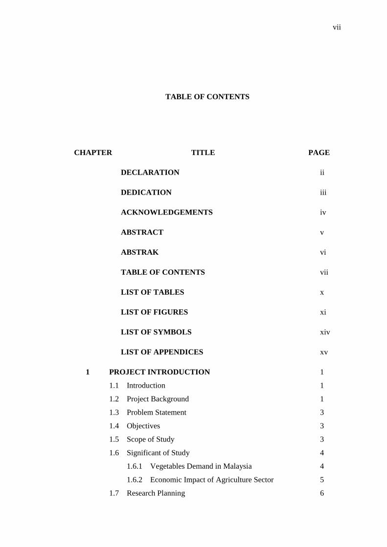
TABLE OF CONTENTS
CHAPTER TITLE PAGE
DECLARATION ii
DEDICATION iii
ACKNOWLEDGEMENTS iv
ABSTRACT v
ABSTRAK vi
TABLE OF CONTENTS vii
LIST OF TABLES x
LIST OF FIGURES xi
LIST OF SYMBOLS xiv
LIST OF APPENDICES xv
1 PROJECT INTRODUCTION 1
1.1 Introduction 1
1.2 Project Background 1
1.3 Problem Statement 3
1.4 Objectives 3
1.5 Scope of Study 3
1.6 Significant of Study 4
1.6.1 Vegetables Demand in Malaysia 4
1.6.2 Economic Impact of Agriculture Sector 5
1.7 Research Planning 6
viii
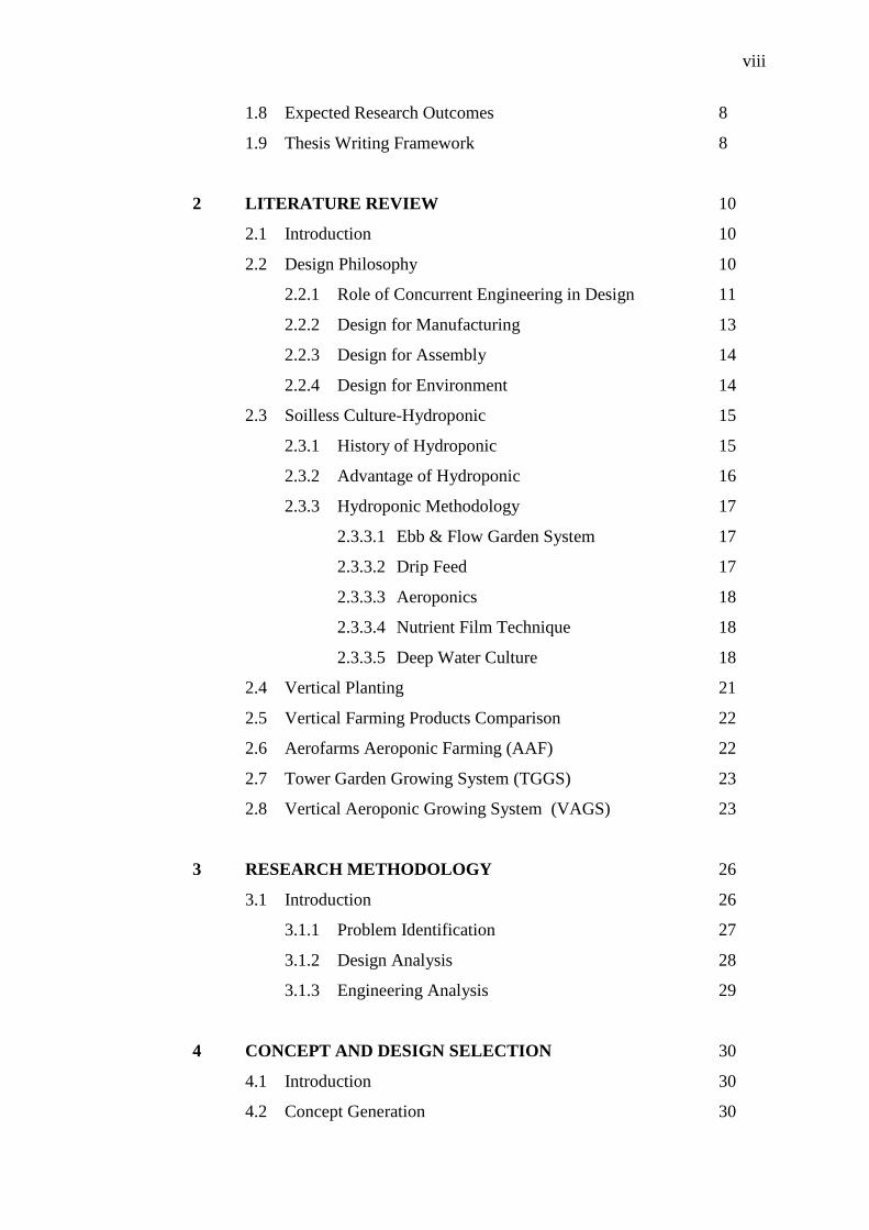
1.8 Expected Research Outcomes 8
1.9 Thesis Writing Framework 8
2 LITERATURE REVIEW 10
2.1 Introduction 10
2.2 Design Philosophy 10
2.2.1 Role of Concurrent Engineering in Design 11
2.2.2 Design for Manufacturing 13
2.2.3 Design for Assembly 14
2.2.4 Design for Environment 14
2.3 Soilless Culture-Hydroponic 15
2.3.1 History of Hydroponic 15
2.3.2 Advantage of Hydroponic 16
2.3.3 Hydroponic Methodology 17
2.3.3.1 Ebb & Flow Garden System 17
2.3.3.2 Drip Feed 17
2.3.3.3 Aeroponics 18
2.3.3.4 Nutrient Film Technique 18
2.3.3.5 Deep Water Culture 18
2.4 Vertical Planting 21
2.5 Vertical Farming Products Comparison 22
2.6 Aerofarms Aeroponic Farming (AAF) 22
2.7 Tower Garden Growing System (TGGS) 23
2.8 Vertical Aeroponic Growing System (VAGS) 23
3 RESEARCH METHODOLOGY 26
3.1 Introduction 26
3.1.1 Problem Identification 27
3.1.2 Design Analysis 28
3.1.3 Engineering Analysis 29
4 CONCEPT AND DESIGN SELECTION 30
4.1 Introduction 30
4.2 Concept Generation 30
ix
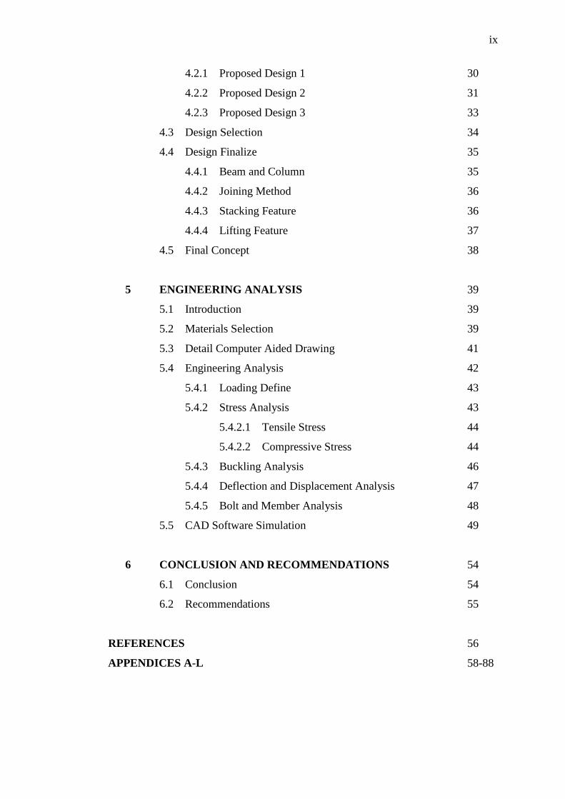
4.2.1 Proposed Design 1 30
4.2.2 Proposed Design 2 31
4.2.3 Proposed Design 3 33
4.3 Design Selection 34
4.4 Design Finalize 35
4.4.1 Beam and Column 35
4.4.2 Joining Method 36
4.4.3 Stacking Feature 36
4.4.4 Lifting Feature 37
4.5 Final Concept 38
5 ENGINEERING ANALYSIS 39
5.1 Introduction 39
5.2 Materials Selection 39
5.3 Detail Computer Aided Drawing 41
5.4 Engineering Analysis 42
5.4.1 Loading Define 43
5.4.2 Stress Analysis 43
5.4.2.1 Tensile Stress 44
5.4.2.2 Compressive Stress 44
5.4.3 Buckling Analysis 46
5.4.4 Deflection and Displacement Analysis 47
5.4.5 Bolt and Member Analysis 48
5.5 CAD Software Simulation 49
6 CONCLUSION AND RECOMMENDATIONS 54
6.1 Conclusion 54
6.2 Recommendations 55
REFERENCES 56
APPENDICES A-L 58-88
x
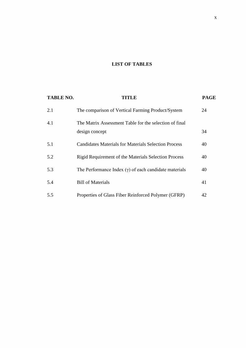
LIST OF TABLES
TABLE NO. TITLE PAGE
2.1 The comparison of Vertical Farming Product/System 24
4.1 The Matrix Assessment Table for the selection of final
design concept 34
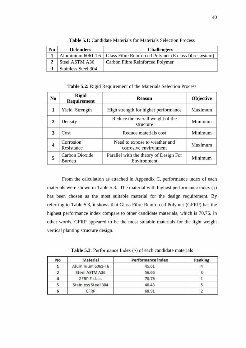
5.1 Candidates Materials for Materials Selection Process 40
5.2 Rigid Requirement of the Materials Selection Process 40
5.3 The Performance Index (γ) of each candidate materials 40
5.4 Bill of Materials 41
5.5 Properties of Glass Fiber Reinforced Polymer (GFRP) 42
xi
LIST OF FIGURES
FIGURE NO. TITLE PAGE
1.1 Food trade of Malaysia from year 2008 to prediction
year 2011 4
1.2 Distribution of imported food in year 2010 5
1.3 The research flow chart of project for PSM 1 & 2 7
2.1 Overall engineering cost 12
2.2 Graph of cost of changes versus the design phase 12
2.3 Ebb & Flow Garden Growing System 19
2.4 Drip Feed System 19
2.5 Aeroponics 20
2.6 Nutrient Film Technique 20
2.7 Deep Water Culture 21
2.8 The Aerofarms Aeroponic Farming 22
2.9 Tower Garden Growing System 23
2.10 Vertical Aeroponic Growing System 24
3.1 Project research methodology 26
3.2 Problem identification flow chart 27
3.3 The process flow for design analysis 28
xii
3.4 Engineering analysis flow chart 29
4.1 The proposed design 1 for the light weight vertical
planting structure 31
4.2 Joints that use in proposed design 1 32
4.3 Proposed design 2 which uses the concept of shipping
container 32
4.4 The view of interior structure of the proposed design 2 32
4.5 Proposed design 3 for vertical planting system 33
4.6 The skeleton structure of the vertical planting structure that
built by structural beam 33
4.7 Design of beams 35
4.8 Design of joint 36
4.9 Design of stacking feature 37
4.10 Design of lifting feature 37
4.11 The isometric view of the final design 38
4.12 The stacking assembly of the vertical planting structure 38
5.1 Vertical planting structure components 41
5.2 The tensile force that act on the box column of the vertical
planting structure 44
5.3 The stacking assembly of the vertical planting structure 45
5.4 The upper and lower parts of the vertical planting structure 46
5.5 Box column 102x102x6.4 (2500) from the vertical planting
structure 46
5.6 Box beam 102x102x6.4 (2398) from the vertical planting
structure 48
xiii
5.7 Joint connection of the vertical planting structure 49
5.8 The stress distribution of the lower part of box column
while under compression loading 50
5.9 The stress distribution of the top part of box column while
under tensile loading 50
5.10 Displacement of box column while under compression
loading 51
5.11 Deflection of box beam while under a point load condition 52
5.12 The stress distribution of corner joint plate 52
5.13 The stress distribution of middle joint plate 53
xiv
LIST OF SYMBOLS
𝜎𝑇 - Tensile Stress
𝐹 - Force
𝐴 - Area
𝑃𝑐𝑟 - Critical Axial Load
𝜋 - Pi (3.142)
𝐸 - Tensile Modulus
𝐼 - Moment of Inertia
𝐾 - Effective Length Factor
𝐿 - Effective Length
𝛿 - Relative Displacement
𝑃 - Compression Force
xv
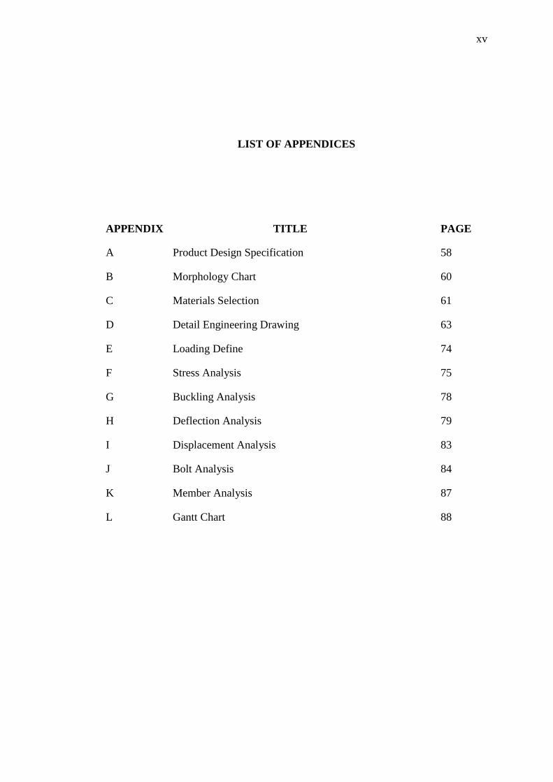
LIST OF APPENDICES
APPENDIX TITLE PAGE
A Product Design Specification 58
B Morphology Chart 60
C Materials Selection 61
D Detail Engineering Drawing 63
E Loading Define 74
F Stress Analysis 75
G Buckling Analysis 78
H Deflection Analysis 79
I Displacement Analysis 83
J Bolt Analysis 84
K Member Analysis 87
L Gantt Chart 88
1
CHAPTER 1
PROJECT INTRODUCTION
1.1 Introduction
This chapter is discussed a brief explanations about the backgrounds of the
project including the objective, scope of study and the project framework of the final
year project. The aim of the project is to design a light weight structure for vertical
planting system as an alternative method for vegetables growing.
1.2 Project Background
Malaysia is a country which is located near the equatorial with a tropical
climate which is very suitable for agriculture activities. Malaysia has a very large
area of land which covers 33 million hectare. In these large area of land, only 6.6
million [1] hectare or equivalent to twenty percent are allocate for agriculture
purpose. Thus, the rest of the areas are used as residential area, industrial, and others.
It is easy to clear a land for agriculture because there still exist a large area of
land which not yet been explored in Malaysia. With the rise in population of
Malaysia, open an agriculture area is not a sustainable method because the land is
still not enough for agriculture to support the population of our country.
2
In the year of 1987, sustainable development was defined as „meet present
needs without compromising the ability of future generations to meet their need‟ [2]
and with the issue of sustainability getting more attention in almost all of the country
around the world, agriculture sector will become one of the sectors that will face
tough challenges in the future development. According to Deputy Chief Minister
Datuk Seri Yahya Hussin in The Star (2010) “higher input in agriculture on an
industrial scale can elevate food production but it also contributes to global warming,
destruction, biological imbalance, loss of land fertility and use of much water.”
There is a very close relationship between the agriculture and environment,
methods that are environmental friendly should be given priority to ensure the
sustainable food supply for the country. In order to minimize the agriculture impact
to the environment, the minister of agriculture of that period of time, had suggested
growing paddy on the roof top of the building and it was successful. Nevertheless,
there is none of the farmer dare to practice this modern technique due to the huge
initial investment of the modern farming technique.
In other to boost agriculture sectors, government has introduced New
Economic Model (NEM). The ability to ensure the continuous food supply in the
context of New Economic Model (NEM) was identified as one of the challenge to
country in order to become a high income country. Therefore, increasing the income
of the farmer and stabilize the food price in the market would be the main challenge
to us. In less than eight years to transforming our country to a high income country,
there is not much different of agriculture technique that is use in Malaysia although
the use of machine, modern method have started to penetrate in this sector. In
connection with this situation, government has identified four strategies [4] to
revitalize agriculture sector, there are:-
i. Enlarge the application of Information and Communication Technology
(ICT)
ii. Develop high quality human capital
iii. Increase the effectiveness of institution involvement in agriculture sector
iv. Application of innovation and technology in agriculture sector
3
In this project, the design of vertical planting system will become an
innovation in the modern farming technique. With the high demand of the vegetable
in Malaysia, an implementation of vertical planting technique will be the solution to
it. Currently, hydroponic are one of the solution to increase the yield of vegetables. A
green house is a simple structure that built to grow vegetables. The built of green
house need to clean up a large area of land, yet the yield is limited. This green house
still can be improved in term of the structure and the yield with a limited area of land.
Thus, the light weight vertical planting structure can be a solution for farmer,
entrepreneur or country to generate higher income in the future.
1.3 Problem Statement
High demand for vegetable is causing our country to spend a lot on importing
food. This shows that the current farming method is not enough to supply the
vegetables demand of our country.
1.4 Objectives
The objective of this project is to design a light weight structure for vertical
planting system with compliance to design for environment concept.
1.5 Scope of Study
The scopes of this project include developing the specifications and propose
design for a light weight structure for vertical planting system. The scope of the
vertical planting should be limited to the growing of herbs, leafy vegetables or
fruiting vegetables in Malaysia. The best solution among the proposed concept for
vertical farming will be chosen based on requirement and detailed engineering

4
drawing will be generated. The safety factor of the structure will be calculated and
the product will be optimized by Computer Aided Design (CAD).
1.6 Significant of Study
1.6.1 Vegetables Demand in Malaysia
Although Malaysia has a large area of land that used for agriculture activities
but it is still not enough to fulfil the demand in our country. At the year of 2011, the
food import‟s value had achieved RM27.93 billion [5] from January until October.
By prediction, the total food import of the year may achieve RM34.45 billion [6].
Figure 1.1 Food trade of Malaysia from year 2008 to prediction year 2011 [6]
Figure 1.1 shows that there is an imbalance between the food export and
import. The money that spent on food importing was always higher than the amount
of export from the year 2009 to 2011. During the year of 2010, Malaysia still remains
as a net food importer. The money spent on importing food had achieved RM30.19
billion [6], which exceeded RM3.51 billion compare to the year of 2009. From
Figure 1.2, with the total food import value of RM30.19 billion, the import of coffee,
tea, cocoa and spices occupying 16.96%, follows by cereal and cereal preparations
2008 2009 2010 2011
Export 17.76 15.71 18.1 20.5
Import 27.92 26.68 30.19 34.45
0
10
20
30
40
Val
ue
(R
M B
illio
n)
Food Trade of Malaysia From 2008-2011(Predict)
5
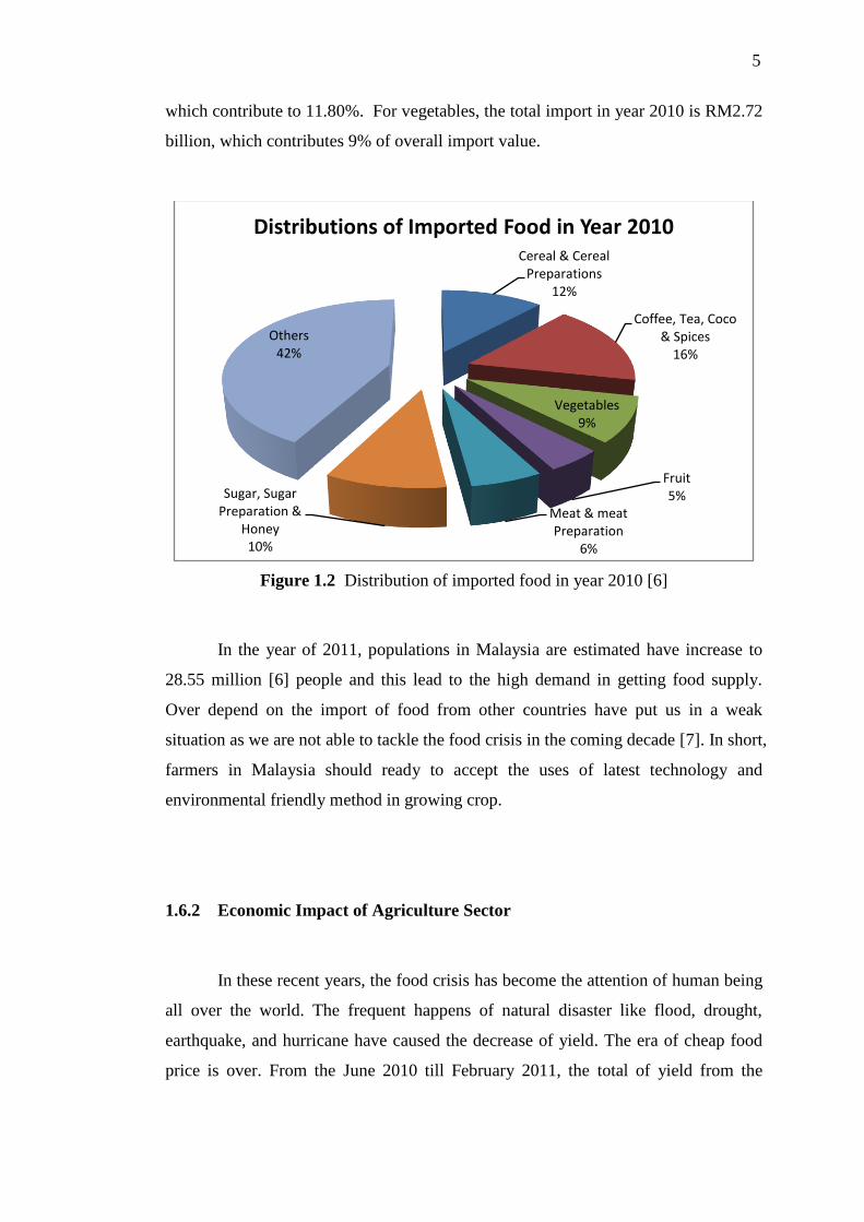
which contribute to 11.80%. For vegetables, the total import in year 2010 is RM2.72
billion, which contributes 9% of overall import value.
Figure 1.2 Distribution of imported food in year 2010 [6]
In the year of 2011, populations in Malaysia are estimated have increase to
28.55 million [6] people and this lead to the high demand in getting food supply.
Over depend on the import of food from other countries have put us in a weak
situation as we are not able to tackle the food crisis in the coming decade [7]. In short,
farmers in Malaysia should ready to accept the uses of latest technology and
environmental friendly method in growing crop.
1.6.2 Economic Impact of Agriculture Sector
In these recent years, the food crisis has become the attention of human being
all over the world. The frequent happens of natural disaster like flood, drought,
earthquake, and hurricane have caused the decrease of yield. The era of cheap food
price is over. From the June 2010 till February 2011, the total of yield from the
Cereal & Cereal Preparations
12%
Coffee, Tea, Coco & Spices
16%
Vegetables9%
Fruit5%
Meat & meat Preparation
6%
Sugar, Sugar Preparation &
Honey10%
Others42%
Distributions of Imported Food in Year 2010
6
countries like China, Russia, and Brazil has decrease significantly due to the draught.
At the same time, Pakistan and Australia also strike with flood [8].
In other point of views, food crisis could be the huge market potential for us
to explore. Land reclamation for agriculture, using innovation method to increase
yield are the tasks that we can do. Even some of the countries like Syria, Oman, and
Dubai already started using science knowledge to create an ecosystem that suitable
for growing crops. There are much of actions that we can take to resist the food crisis
and explore the unlimited market potential like developing vertical planting system
in our country.
1.7 Research Planning
The project was divided into 2 phases which each phases were consume 1
semester to complete. Phase 1 of the project was concentrate on information
searching, background studies, and research planning. Then, the project was continue
with phase 2 of the project which the procedures are concept generation, final
concept evaluation, engineering analysis and conclusion or recommendations for
further studies of the project. At the end, a structure with detail dimensions was
expected as the result of the project. In short, the phase 1 was concentrated on the
aspect of design while the phase 2 was focus on design analysis. Figure 1.3 shows
the entire procedure flow chart of the design of light weight structure for vertical
planting system:

7
Figure 1.3 The research flow chart of project for PSM 1 & 2

8
1.8 Expected Research Outcomes
At the end of this project, a design of a light weight structure for vertical
planting system will be developed. This project focus on the design of the structure,
but the other supporting components selection will be added in as the support of the
study.
1.9 Thesis Writing Framework
The thesis consist of six chapters, each chapter was lead the project from the
background of the problems to the details of the design and the recommendations for
further study. The details of each chapter are planned as below:-
Chapter one is the introduction of the whole project by identify the system
design requirement. The project background is discussed in this chapter
which includes the scope of study, significant of study, objective, and
research planning.
Chapter two is discussing on the literature of the related studies. The
literatures were divided into two categories which are theory and field studies.
The theories that apply are including the philosophy of design and some
design theory. For the field studies, it is related to the agriculture methods and
the studies of current product in the market.
Chapter three provides the research methodology that used in the whole
project. In this chapter, the details of each design steps were determined.
Chapter four is about the concept design and design selection. Three
concepts will be evaluated and critics in order to fulfil the design criteria and
the concept were finalized.
Chapter five is the engineering analysis of the final concept. The details of
the design like the dimensions of the product will be finalize in this stage and
modelling process was done by using Computer Aided Design (CAD)
software. Safety factor of each component was calculated and optimized.

9
Chapter six is the conclusion and recommendations of the project. The
chapter is discussing the outcome of the project. Besides that,
recommendations were made for further improve of the design.
CHAPTER 2
LITERATURE REVIEW
2.1 Introduction
This chapter discusses about the apply theory of use like design philosophy,
the role of concurrent engineering in the design field, and some theories of design.
Besides that, some apply field of studies like the definition of vertical planting and
some available products in the market were studied.
2.2 Design Philosophy
Design can be define as an activity that using theories of scientific, technical
information and imagination in solving a problem. Design is not a process or
activities that suddenly comes to a person mind, while design is a process that
consume a lot of time and energy before it comes to a real product, which include the
process of ideal generation, testing and modification until it achieve the desired
specifications. A new product always been introduce to the market are based on two
main reasons which are the market demand and the changes of technology. Market
demand is one of the reasons because the user needs new innovation or invention in
solving their problem. Besides that, the advanced technology always substitutes the
old technology to improve the efficiency of a product.
11
2.2.1 Role of Concurrent Engineering (CE) in Design
Concurrent engineering, also refer as parallel engineering or simultaneous
engineering have broaden the focus of processing, functional requirement, operating
limits of the product to account for the „customer‟ as one of the aspect that
previously not to consider in the design phase. Compare to conventional engineering,
lack of communication between designer and manufacturer may slow down the
overall product development time and increase the cost.
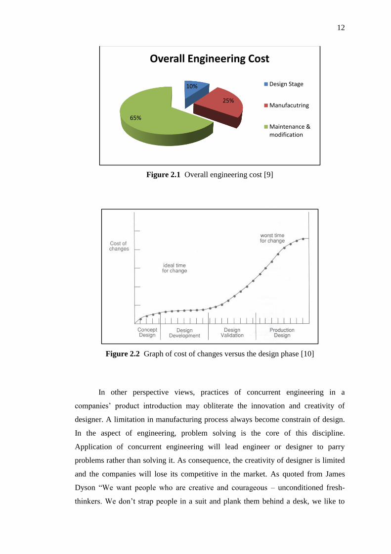
The studies by Institute for Defense Analysis [9] on the experience with
military aircraft had reveals that the modifications and maintenance of the product
are the main cause of increasing in overall engineering cost. Except the operational
cost, only 10% of the engineering cost is spent on design stage, around 25% is taken
by manufacturing process and remain of 65% are the expenses for modification and
maintenance of the design which as shown in Figure 2.1.
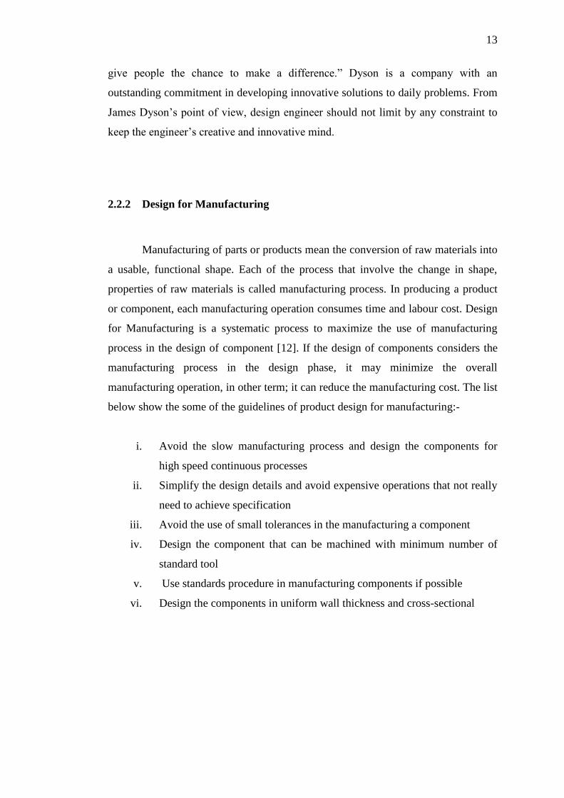
From the studies of Institute for Defense Analysis, we can know that the role
of designer at the beginning of the design process is important. Any decision and
specification that made in the design phase will influence the remains of the life-
cycle. Refer to Figure 2.2, the graph shows the extra expenses on the changes of
design in each stage. During the initial stage (concept design phase), the changes of
design would not cost so much, but the extra cost that spent on the changes of design
may increase as the design phase keep moving forward. When the design phase
comes to the production stage, it is no longer suitable for changing. According to
Salzberg and Watkins [11], the lack of information in the conceptual design phase is
the factor that contributes to the rises of the design problem in the manufacturing
process. Traditionally, designers work as „over-the-wall approach‟ which the
designer design the product, and pass the concept to the manufacturing engineer,
who need to solve various manufacturing problems as they are not involve in the
initial design stage. However, the concurrent engineering can avoid this problem and
helps them to study the proposed design in the point of view of manufacturing
constraint and cost before it comes to production phase.
12
Figure 2.1 Overall engineering cost [9]
Figure 2.2 Graph of cost of changes versus the design phase [10]
In other perspective views, practices of concurrent engineering in a
companies‟ product introduction may obliterate the innovation and creativity of
designer. A limitation in manufacturing process always become constrain of design.
In the aspect of engineering, problem solving is the core of this discipline.
Application of concurrent engineering will lead engineer or designer to parry
problems rather than solving it. As consequence, the creativity of designer is limited
and the companies will lose its competitive in the market. As quoted from James
Dyson “We want people who are creative and courageous – unconditioned fresh-
thinkers. We don‟t strap people in a suit and plank them behind a desk, we like to
10%
25%
65%
Overall Engineering Cost
Design Stage
Manufacutring
Maintenance & modification
13
give people the chance to make a difference.” Dyson is a company with an
outstanding commitment in developing innovative solutions to daily problems. From
James Dyson‟s point of view, design engineer should not limit by any constraint to
keep the engineer‟s creative and innovative mind.
2.2.2 Design for Manufacturing
Manufacturing of parts or products mean the conversion of raw materials into
a usable, functional shape. Each of the process that involve the change in shape,
properties of raw materials is called manufacturing process. In producing a product
or component, each manufacturing operation consumes time and labour cost. Design
for Manufacturing is a systematic process to maximize the use of manufacturing
process in the design of component [12]. If the design of components considers the
manufacturing process in the design phase, it may minimize the overall
manufacturing operation, in other term; it can reduce the manufacturing cost. The list
below show the some of the guidelines of product design for manufacturing:-
i. Avoid the slow manufacturing process and design the components for
high speed continuous processes
ii. Simplify the design details and avoid expensive operations that not really
need to achieve specification
iii. Avoid the use of small tolerances in the manufacturing a component
iv. Design the component that can be machined with minimum number of
standard tool
v. Use standards procedure in manufacturing components if possible
vi. Design the components in uniform wall thickness and cross-sectional
14
2.2.3 Design for Assembly
Design for Assembly is a systematic procedure to maximize the use of
components in the design of a product [12]. The procedure of maximizing the uses of
component also means the simplification of the product so that the overall cost of
assembly is reduced. Design for Assembly is important in the beginning of design
phase as it need to analyze the part component and the whole product for the
assembly problem to achieve the target on easy, low-cost and functionality. There are
some basic guidelines for Design for Assembly:-
i. Minimize components count by incorporating maximum functions into
single component
ii. Modularize multiple parts into single subassemblies
iii. Standardize to reduce the part variety
iv. Design the mating features for easy insertion
v. Provide orienting features on un-symmetries
vi. Eliminate fasteners
2.2.4 Design for Environment
The concept of Design for Environment firstly introduced in the early of
1990s to built environmental awareness into the product development efforts. Design
for Environment also may refer to Eco-design, Life Cycle Design, Design for Eco-
efficiency and Sustainable Design. According to Joseph Fiksel:
“ Design for Environment is the systematic consideration of design performance
with respect to environmental, health, safety, and sustainability objectives over the
full product and process life cycle” [13].
Typically, there are obviously a broad range of guidelines and practices that
can be considered. In short, the Design for Environment are divided into four
principles strategies:-

15
i. Design for Dematerialization refers to the reducing of the total amount of
materials as well the corresponding energy requirements, for a product and its
associated processes throughout their life cycle.
ii. Design for Detoxification refers to reduce and eliminate the poisonous, toxic,
and hazardous product or by-product that affects the humans or the
environment.
iii. Design for Revalorization refers to recover, recycle, or otherwise reuse the
residual materials and energy that generated at each stage of the product life
cycle, thus eliminating waste and reducing virgin resource requirements.
iv. Design for Capital Protection and Renewal seeks to ensure the safety,
integrity, vitality, productivity, and continuity of the human, natural, and
economic resources that are needed to sustain the product life cycle.
2.3 Soilless Culture - Hydroponic
In last few decades, the world of agriculture has shifted dramatically with the
rise in human population and the living standard, the demand for food is getting
higher. The consequence of this situation had lead to the changes of agriculture
method, from conventional soil growing to a soilless culture - hydroponic.
2.3.1 History of Hydroponic
The word „Hydroponics‟ was coined by Dr. W.F. Gericke [14], a professor
from University of California in year 1934 to describe the cultivation of both edible
and ornamental plants in a solution of water and dissolved nutrients without the
presence of soil medium. The word „Hydroponics‟ is derived parallel relationship
with the word “Geoponics”, the Greek word meaning “Earth Working”, or literally
“agriculture”.
16
The earliest published work on hydroponics was in year of 1627, this concept
has actually been developed as early as the pyramids time when the citizen had
successfully built one of the Seven Wonders of the World - Hanging Garden of
Babylon.
2.3.2 Advantages of Hydroponics
By practicing hydroponic methods, plants are grown healthier than soil
grown counterparts since the plant received a balanced diet and do not come into
contact with the soil borne pests and diseases. High efficient hydroponics system can
prevent the evaporation of solution and hence conserve the nutrients and the water
needed by the plants to grow. Meanwhile, unlike the conventional agriculture
methods, hydroponic crops can grow closer without starving for nutrient in a
confined space. This is commercially important since healthier crops can be grown in
larger amount at once (higher productivity). Furthermore, hydroponically grown
cultivation can cut-off the soil preparation cost, insecticides, fungicides and losses
due to drought and ground flooding.
In other point of views, plants normally waste huge amount of energy to
develop their roots to search for the sufficient nutrient and water under the ground.
However, this energy can be conserved in hydroponic crops since the nutrient and
water are supplied directly to their roots. As a result, the conserved energy can be
redirected to the production of more foliage, flowers, fruits and vegetable.
Moreover, hydroponics farming has been known as the eco-friendly farming
method due to its low consumption of water and fertilizer usage compared to the
conventional growing method. In traditional farming, forests or the old grown
cultivation on a land are burnt into ashes to produce soil enriched with nutrient for
the next production of crops. This has raised a lot of environmental issues that can be
actually avoided. The nutrient used for hydroponics farming is non-toxic and hence it
creates no harm to the natural ecosystem.
17
2.3.3 Hydroponic Methodology
There are several types of hydroponic system that commonly practice by
farmers. Each hydroponic system has its own advantages and limitation in growing
vegetables. The detail of each hydroponic system was discussed in section below.
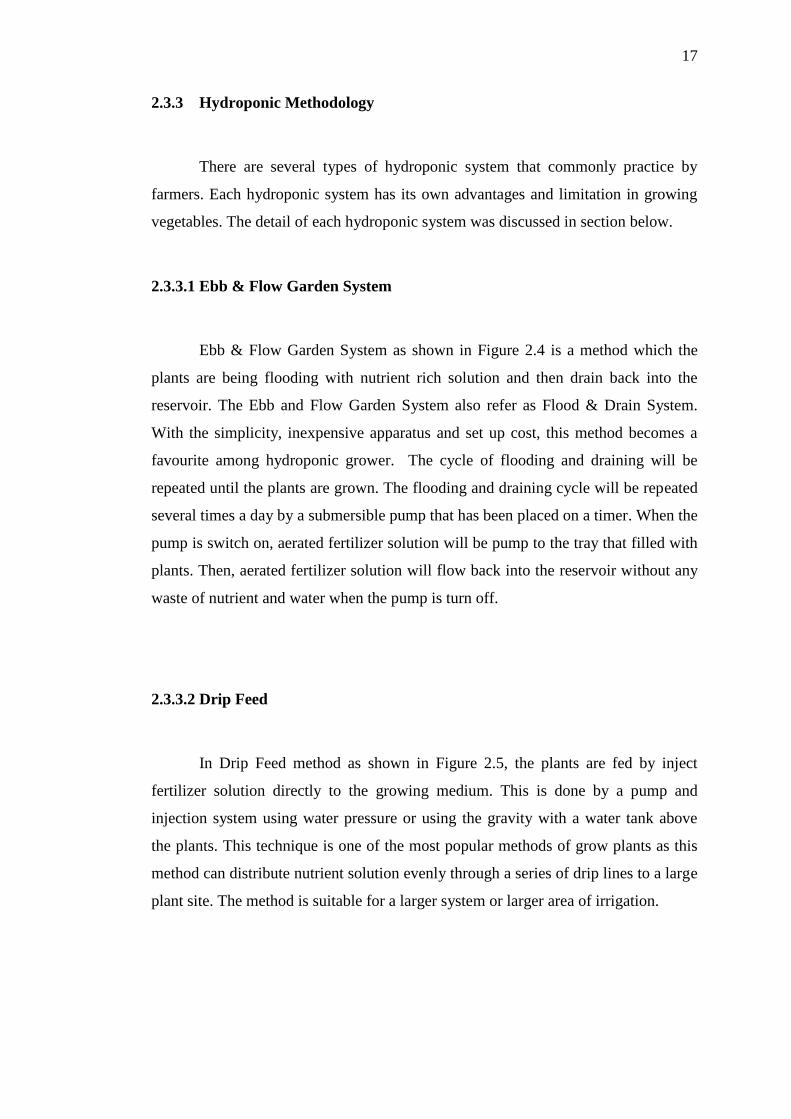
2.3.3.1 Ebb & Flow Garden System
Ebb & Flow Garden System as shown in Figure 2.4 is a method which the
plants are being flooding with nutrient rich solution and then drain back into the
reservoir. The Ebb and Flow Garden System also refer as Flood & Drain System.
With the simplicity, inexpensive apparatus and set up cost, this method becomes a
favourite among hydroponic grower. The cycle of flooding and draining will be
repeated until the plants are grown. The flooding and draining cycle will be repeated
several times a day by a submersible pump that has been placed on a timer. When the
pump is switch on, aerated fertilizer solution will be pump to the tray that filled with
plants. Then, aerated fertilizer solution will flow back into the reservoir without any
waste of nutrient and water when the pump is turn off.
2.3.3.2 Drip Feed
In Drip Feed method as shown in Figure 2.5, the plants are fed by inject
fertilizer solution directly to the growing medium. This is done by a pump and
injection system using water pressure or using the gravity with a water tank above
the plants. This technique is one of the most popular methods of grow plants as this
method can distribute nutrient solution evenly through a series of drip lines to a large
plant site. The method is suitable for a larger system or larger area of irrigation.

18
2.3.3.3 Aeroponics
In Aeroponics methods, growing plants are suspended in the air as shown in
Figure 2.6. The nutrient solution will be spray direct to the roots. This technique is
suitable for growing root vegetables. The grower can harvest the plant roots without
removing the plant. The overall set up cost and operation cost are relatively higher
than other hydroponics methods as the zero growing medium is used. Without
growing medium, the plants need moist at all the times by running the pump
continuously or extremely high frequency which will lead to the increase of
electricity usage. Therefore, the Aeroponic method is rarely applied for the
commercial use.
2.3.3.4 Nutrient Film Technique
Nutrient Film Technique fed the plants by constantly flow a thin film of
nutrient solution across the plant roots in the tray of pipe. This method has the same
problem as the Aeroponic, which the roots of the plant may dry out in a very short
time once the pump failure or shut down. This problem may be solving by increase
the growing medium by adding Perlite or lava stones to keep moisture. This method
is relatively simple in term of components compare to drip feed and suitable for
growing leafy vegetables and herbs at the commercial production level as shown in
Figure 2.7.
2.3.3.5 Deep Water Culture (DWC)
Deep Water Culture is one of the hydroponic methods that roots are
submerged in nutrient solution with air are provided by air pump or air stone. This
method is simple and can ensure the high level of humidity in the root zone. There is
limitation of this method, if the source of oxygen in the nutrient solution is low, the
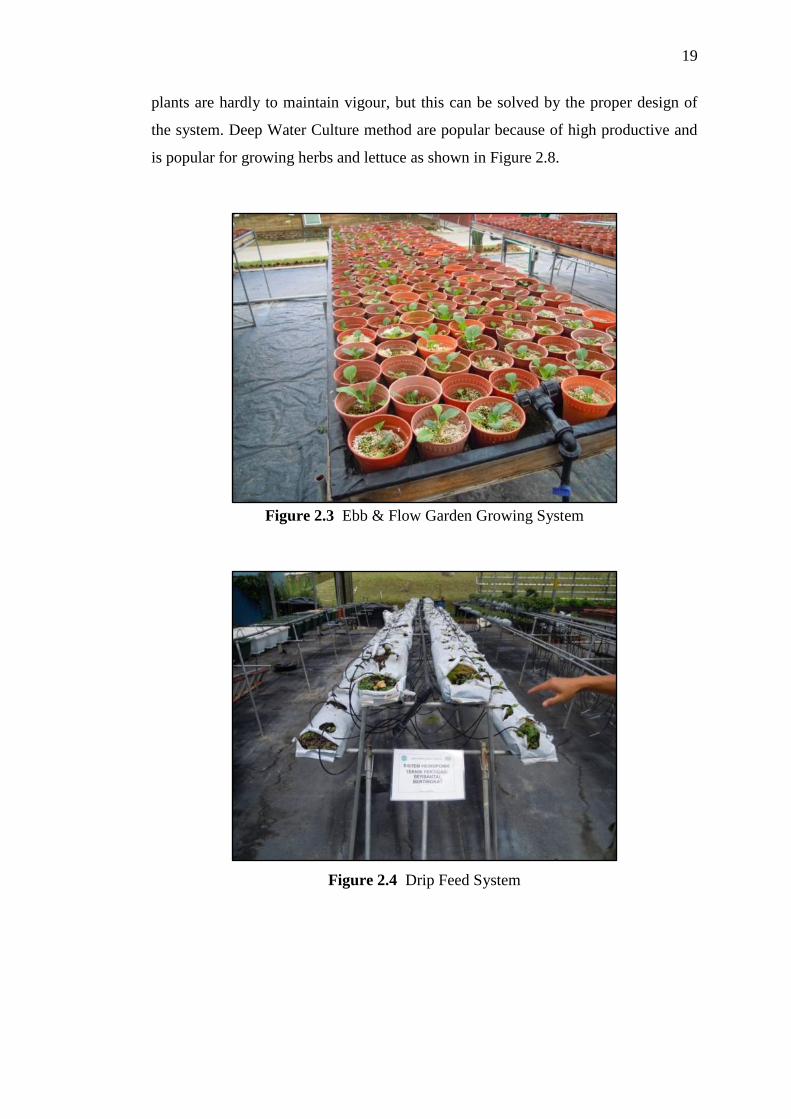
19
plants are hardly to maintain vigour, but this can be solved by the proper design of
the system. Deep Water Culture method are popular because of high productive and
is popular for growing herbs and lettuce as shown in Figure 2.8.
Figure 2.3 Ebb & Flow Garden Growing System
Figure 2.4 Drip Feed System

20
Figure 2.5 Aeroponics
Figure 2.6 Nutrient Film Technique.
21
Figure 2.7 Deep Water Culture
2.4 Vertical Planting
Indoor farming is not a new practice since the greenhouse production of
vegetables has been in vogue for a long time. Now, an entirely new development of
indoor farming has to be invented with applying advanced technology to
accommodate the demand of food in the future. Plant the food vertically can be the
solution for it! Vertical Farming was first suggested in the year 1999 by Dickson
Despommier, a professor of environmental health at Columbia University in New
York City [17]. In urban city, high rise building was built to solve the problem of
lack of land; it is the same concept that applies in vertical farming. New era of
agriculture will shift from country side to high population urban city, and even in the
high rise building in the business area.
In an ideal situation, vertical farming can bring a lot of advantages to
environment, social and human. The major advantages are as follows:-
i. Increase the yield by precise climate control
ii. Safe from natural disaster that will cause reduce in yield
iii. Reduce environment pollution

22
iv. Encourage ecosystem recovery
v. Reduce Carbon Footprint
vi. Generate renewable energy from biomass
2.5 Vertical Farming Products Comparison
There are many products available in the market. In this section, the products
that related to vertical farming were being chosen and analyzed. The information will
be tabulated in table form for easy comparison between each product.
2.5.1 Aerofarms Aeroponic Farming (AAF)
The plants are grown without sunlight and soil is the special characteristic of
Aerofarms. Without the needs of sunlight, it can provide yield year round and in any
location. This Aerofarms Aeroponic Farming is designed in modular form, which
can be vertically stackable with an external support structure. Aerofarms able to
generate profit and applied in commercial scale production in urban city.
Figure 2.8 The Aerofarms Aeroponic Farming [18]

23
2.5.2 Tower Garden Growing System (TGGS)
The Tower Garden Growing System is a product that promotes vertical
farming. Tower Garden Growing System applied Aeroponic method which the
nutrient solution will be directly fed to the roots. This five feet tall Aeroponic
vertical garden with components of net pots, pump and drain tube allow growing of
20 plants together with a shorter time to harvest compare to conventional farming
method.
Figure 2.9 Tower Garden Growing System [19]
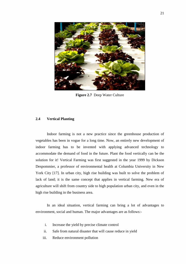
2.5.3 Vertical Aeroponic Growing System (VAGS)
The Vertical Aeroponic Growing System contains a Bio-shelter Structure
which provides a suitable growing environment to the plants. There are many
vertical aeroponic growing tubes utilize in the system to increase the yield of plant in
a limit area. This Vertical Aeroponic Growing System can achieve 6 to 7 times the
output of a conventional greenhouse [20]. The types of plant that can be grown in
this system include garden vegetables, berries, flower, and herbs.
24
Figure 2.10 Vertical Aeroponic Growing System [20]
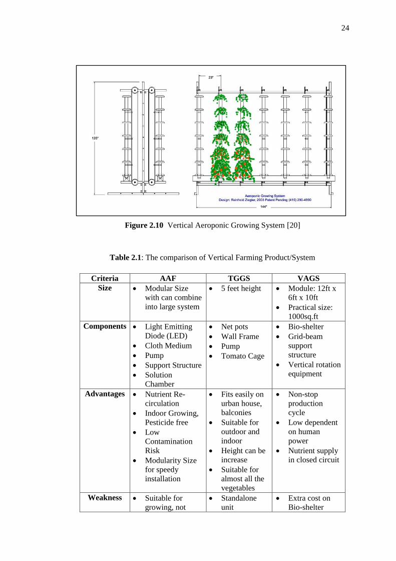
Table 2.1: The comparison of Vertical Farming Product/System
Criteria AAF TGGS VAGS
Size Modular Size
with can combine
into large system
5 feet height Module: 12ft x
6ft x 10ft
Practical size:
1000sq.ft
Components Light Emitting
Diode (LED)
Cloth Medium
Pump
Support Structure
Solution
Chamber
Net pots
Wall Frame
Pump
Tomato Cage
Bio-shelter
Grid-beam
support
structure
Vertical rotation
equipment
Advantages Nutrient Re-
circulation
Indoor Growing,
Pesticide free
Low
Contamination
Risk
Modularity Size
for speedy
installation
Fits easily on
urban house,
balconies
Suitable for
outdoor and
indoor
Height can be
increase
Suitable for
almost all the
vegetables
Non-stop
production
cycle
Low dependent
on human
power
Nutrient supply
in closed circuit
Weakness Suitable for
growing, not
Standalone
unit
Extra cost on
Bio-shelter
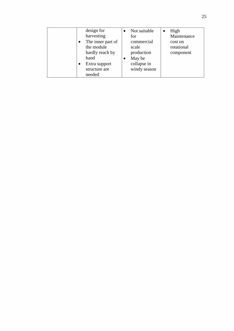
25
design for
harvesting
The inner part of
the module
hardly reach by
hand
Extra support
structure are
needed
Not suitable
for
commercial
scale
production
May be
collapse in
windy season
High
Maintenance
cost on
rotational
component

CHAPTER 3
RESEARCH METHODOLOGY
3.1 Introduction
In this chapter, project methodology was discussed in details. The
methodology for the project was divided into 4 parts which were preliminary data
analysis, design analysis, engineering analysis and simulation. Figure 3.1 shows the
brief research methodology for the project. Each part was discussed further in the
following sections.
Figure 3.1 Project research methodology
Start
Problem Identification
Design Analysis
Engineering Analysis
End
27
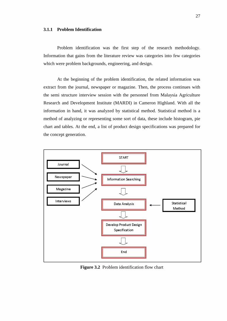
3.1.1 Problem Identification
Problem identification was the first step of the research methodology.
Information that gains from the literature review was categories into few categories
which were problem backgrounds, engineering, and design.
At the beginning of the problem identification, the related information was
extract from the journal, newspaper or magazine. Then, the process continues with
the semi structure interview session with the personnel from Malaysia Agriculture
Research and Development Institute (MARDI) in Cameron Highland. With all the
information in hand, it was analyzed by statistical method. Statistical method is a
method of analyzing or representing some sort of data, these include histogram, pie
chart and tables. At the end, a list of product design specifications was prepared for
the concept generation.
Figure 3.2 Problem identification flow chart
28
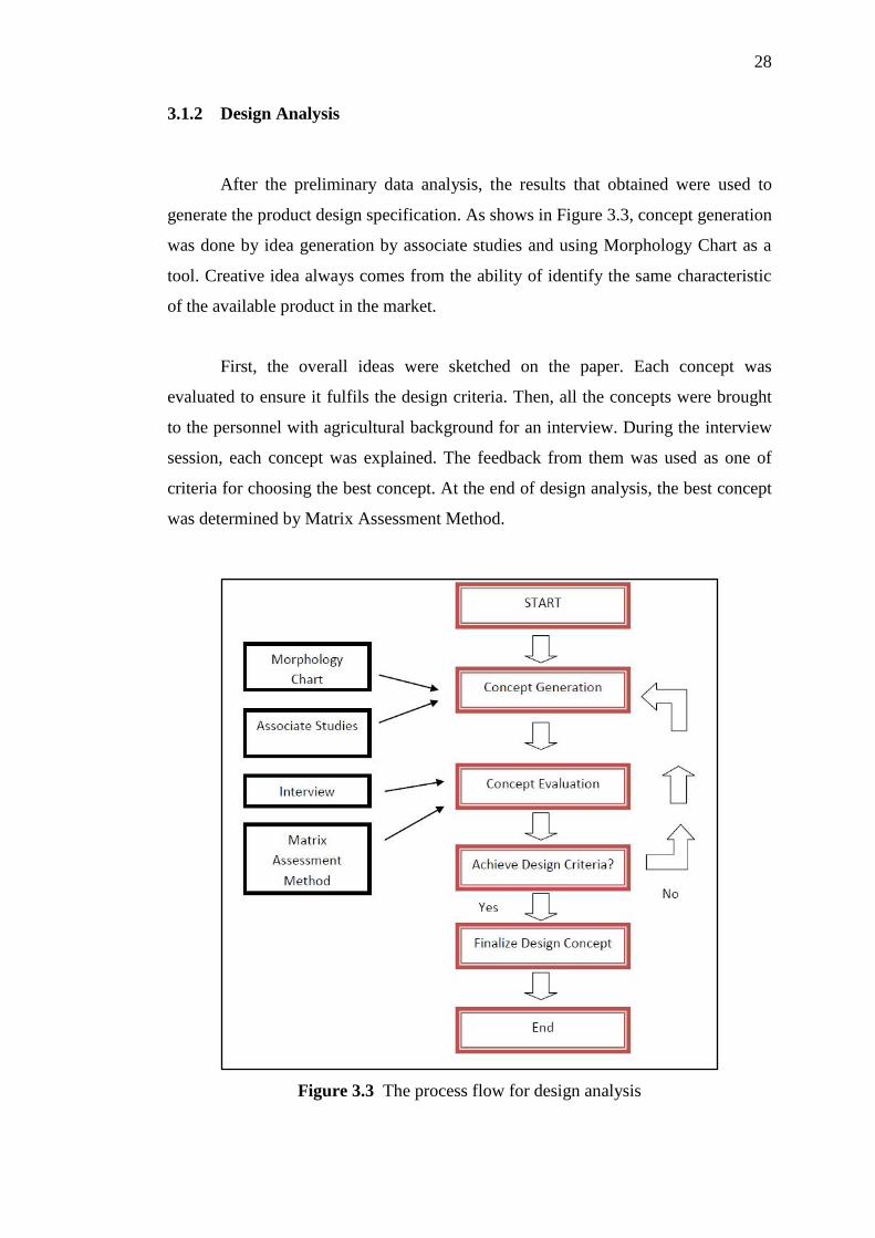
3.1.2 Design Analysis
After the preliminary data analysis, the results that obtained were used to
generate the product design specification. As shows in Figure 3.3, concept generation
was done by idea generation by associate studies and using Morphology Chart as a
tool. Creative idea always comes from the ability of identify the same characteristic
of the available product in the market.
First, the overall ideas were sketched on the paper. Each concept was
evaluated to ensure it fulfils the design criteria. Then, all the concepts were brought
to the personnel with agricultural background for an interview. During the interview
session, each concept was explained. The feedback from them was used as one of
criteria for choosing the best concept. At the end of design analysis, the best concept
was determined by Matrix Assessment Method.
Figure 3.3 The process flow for design analysis

29
3.1.3 Engineering Analysis
Figure 3.4 shows the process flow for the engineering analysis. From the final
concept, detailed dimension was determined. A modelling process was started by
using Computer Aided Design (CAD) called Solidworks. Solidworks is a powerful
tool for Three Dimensional (3-D) modelling. After modelling process, a materials
selection process was come in for proper materials selection of the product.
Weighted Property Method was used as a tool for materials selection as this method
is easy and can shown the different characteristic of materials on the performance
need of the product. With proper materials selection, each component’s stress
distribution and safety factor was calculated and stimulated by Solidworks
SimulationXpress. If the safety of the component is not achieved, the process will
loop back to the modelling process to modify the design of the components. At the
end, detailed dimension and simulation of each component was ready.
Figure 3.4 Engineering analysis flow chart
CHAPTER 4
CONCEPT AND DESIGN SELECTION
4.1 Introduction
In this chapter, the development of final design of light weight structure for
vertical planting system was discussed. Each proposed designs were evaluated and
the best proposed design was proceed to next phase.
4.2 Concept Generation
There were 3 proposed designs of light weight vertical structure for vertical
planting system. Ideas of these 3 proposed design was come from the Morphology
chart as attached in Appendix B. Each proposed design has its own special features
and characteristics.
4.2.1 Proposed Design 1
The overall concept for the proposed design 1 was shown in Figure 4.1. The
main structure column or beam was square in shape since this can contribute to
higher second moment of area compare to other shape. Besides that, the simple
square shape beam can be joint easily compare to other shape like round shape. In
31
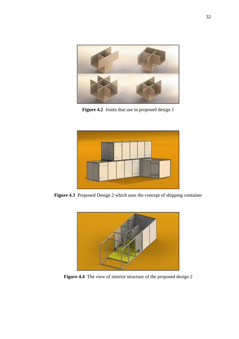
order to design the structure into easy assembly, there was standard joint for all
connection as shown in Figure 4.2. Each joint was secure by using screws or bolts for
stronger connection. For the roof structure, the design of triangle shape can provide
natural ventilation of the structure. On the other aspect, the hydroponic system that
proposed in this design was Ebb & Flow Garden Growing System. This hydroponic
system is the most common system that applied for commercial purpose because of
its high production rate with precise control of water flow.
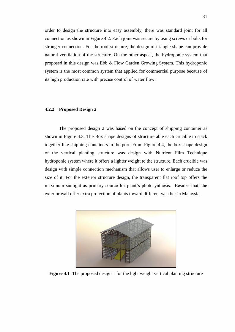
4.2.2 Proposed Design 2
The proposed design 2 was based on the concept of shipping container as
shown in Figure 4.3. The Box shape designs of structure able each crucible to stack
together like shipping containers in the port. From Figure 4.4, the box shape design
of the vertical planting structure was design with Nutrient Film Technique
hydroponic system where it offers a lighter weight to the structure. Each crucible was
design with simple connection mechanism that allows user to enlarge or reduce the
size of it. For the exterior structure design, the transparent flat roof top offers the
maximum sunlight as primary source for plant’s photosynthesis. Besides that, the
exterior wall offer extra protection of plants toward different weather in Malaysia.
Figure 4.1 The proposed design 1 for the light weight vertical planting structure
32
Figure 4.2 Joints that use in proposed design 1
Figure 4.3 Proposed Design 2 which uses the concept of shipping container
Figure 4.4 The view of interior structure of the proposed design 2
33
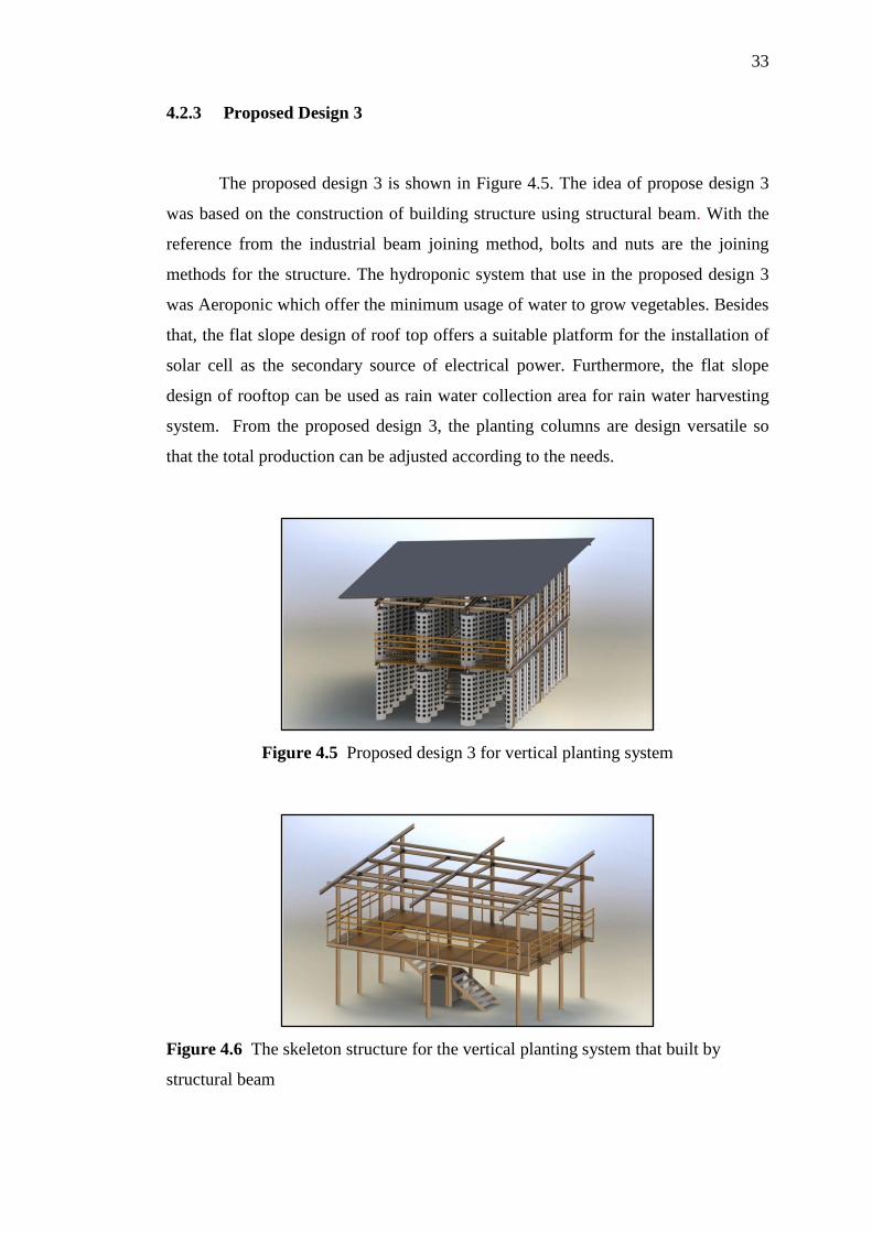
4.2.3 Proposed Design 3
The proposed design 3 is shown in Figure 4.5. The idea of propose design 3
was based on the construction of building structure using structural beam. With the
reference from the industrial beam joining method, bolts and nuts are the joining
methods for the structure. The hydroponic system that use in the proposed design 3
was Aeroponic which offer the minimum usage of water to grow vegetables. Besides
that, the flat slope design of roof top offers a suitable platform for the installation of
solar cell as the secondary source of electrical power. Furthermore, the flat slope
design of rooftop can be used as rain water collection area for rain water harvesting
system. From the proposed design 3, the planting columns are design versatile so
that the total production can be adjusted according to the needs.
Figure 4.5 Proposed design 3 for vertical planting system
Figure 4.6 The skeleton structure for the vertical planting system that built by
structural beam
34
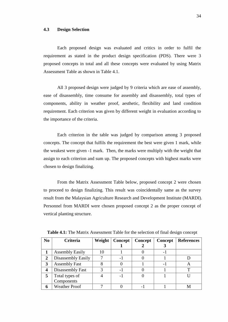
4.3 Design Selection
Each proposed design was evaluated and critics in order to fulfil the
requirement as stated in the product design specification (PDS). There were 3
proposed concepts in total and all these concepts were evaluated by using Matrix
Assessment Table as shown in Table 4.1.
All 3 proposed design were judged by 9 criteria which are ease of assembly,
ease of disassembly, time consume for assembly and disassembly, total types of
components, ability in weather proof, aesthetic, flexibility and land condition
requirement. Each criterion was given by different weight in evaluation according to
the importance of the criteria.
Each criterion in the table was judged by comparison among 3 proposed
concepts. The concept that fulfils the requirement the best were given 1 mark, while
the weakest were given -1 mark. Then, the marks were multiply with the weight that
assign to each criterion and sum up. The proposed concepts with highest marks were
chosen to design finalizing.
From the Matrix Assessment Table below, proposed concept 2 were chosen
to proceed to design finalizing. This result was coincidentally same as the survey
result from the Malaysian Agriculture Research and Development Institute (MARDI).
Personnel from MARDI were chosen proposed concept 2 as the proper concept of
vertical planting structure.
Table 4.1: The Matrix Assessment Table for the selection of final design concept
No Criteria Weight Concept
1
Concept
2
Concept
3
References
1 Assembly Easily 10 1 0 -1
2 Disassembly Easily 7 -1 0 1 D
3 Assembly Fast 8 0 1 -1 A
4 Disassembly Fast 3 -1 0 1 T
5 Total types of
Components
4 -1 0 1 U
6 Weather Proof 7 0 -1 1 M
35
7 Aesthetic 4 0 1 -1
8 Flexibility 7 0 1 -1
9 Land Condition 5 1 -1 0
Total '+' 2 4 3 0
Total '-' 2 2 5 0
Overall Total 0 2 -2 0
Grand Total 1 7 -8 0
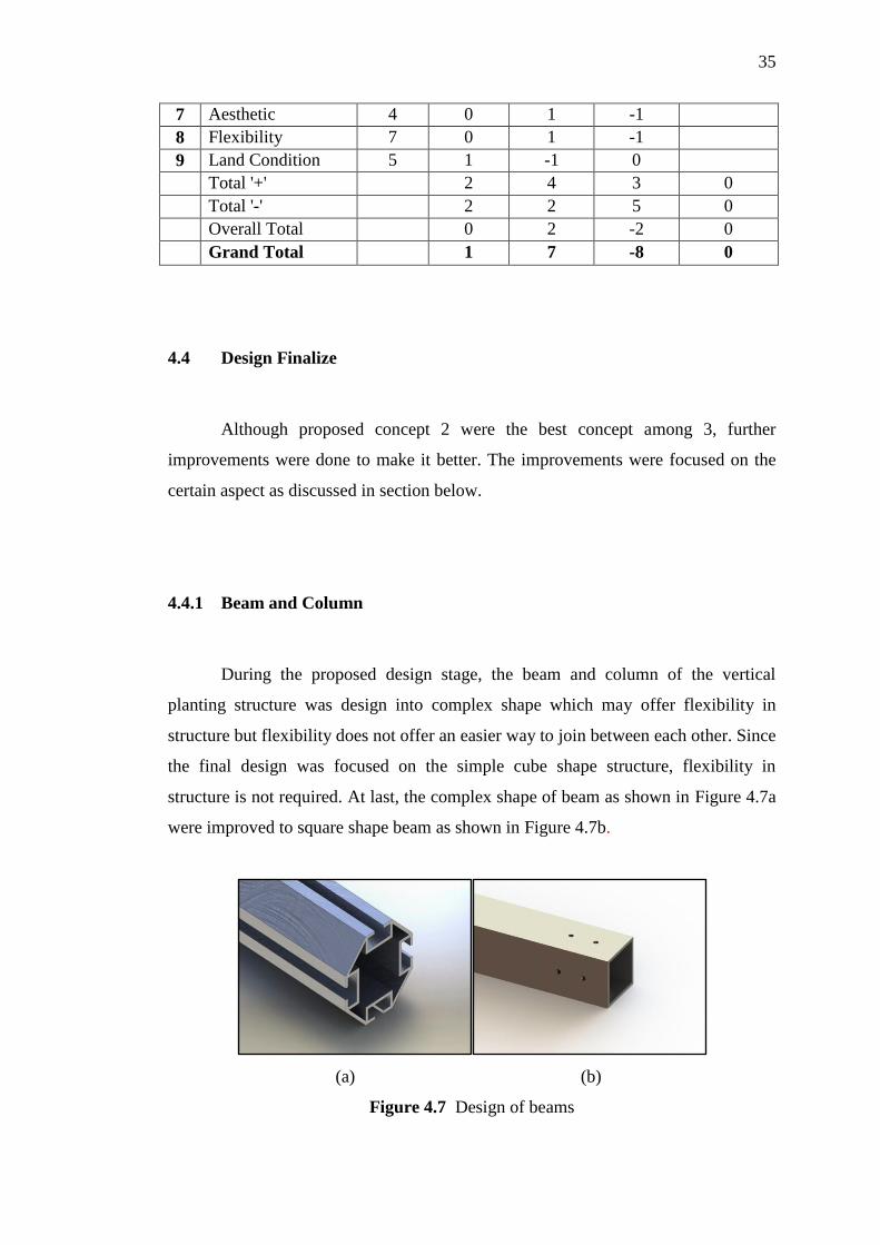
4.4 Design Finalize
Although proposed concept 2 were the best concept among 3, further
improvements were done to make it better. The improvements were focused on the
certain aspect as discussed in section below.
4.4.1 Beam and Column
During the proposed design stage, the beam and column of the vertical
planting structure was design into complex shape which may offer flexibility in
structure but flexibility does not offer an easier way to join between each other. Since
the final design was focused on the simple cube shape structure, flexibility in
structure is not required. At last, the complex shape of beam as shown in Figure 4.7a
were improved to square shape beam as shown in Figure 4.7b.
(a) (b)
Figure 4.7 Design of beams
36
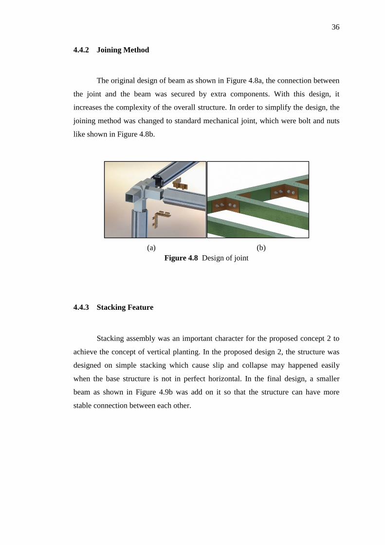
4.4.2 Joining Method
The original design of beam as shown in Figure 4.8a, the connection between
the joint and the beam was secured by extra components. With this design, it
increases the complexity of the overall structure. In order to simplify the design, the
joining method was changed to standard mechanical joint, which were bolt and nuts
like shown in Figure 4.8b.
(a) (b)
Figure 4.8 Design of joint
4.4.3 Stacking Feature
Stacking assembly was an important character for the proposed concept 2 to
achieve the concept of vertical planting. In the proposed design 2, the structure was
designed on simple stacking which cause slip and collapse may happened easily
when the base structure is not in perfect horizontal. In the final design, a smaller
beam as shown in Figure 4.9b was add on it so that the structure can have more
stable connection between each other.

37
(a) (b)
Figure 4.9 Design of stacking feature
4.4.4 Lifting Feature
When the structure need to lift to higher place, a simple joint is needed to
perform the task. From the proposed design 2, the concept used was lifting the
skeleton structure to the higher place and assembly the accessories parts on the spot.
After the consideration, the design was improved. A circular tube was added into the
box beam which use to connection of stacking. While lifting procedure was needed, a
hanger can add on it like shown in Figure 4.10 and the structure is ready to lift.
Figure 4.10 Design of lifting feature
38
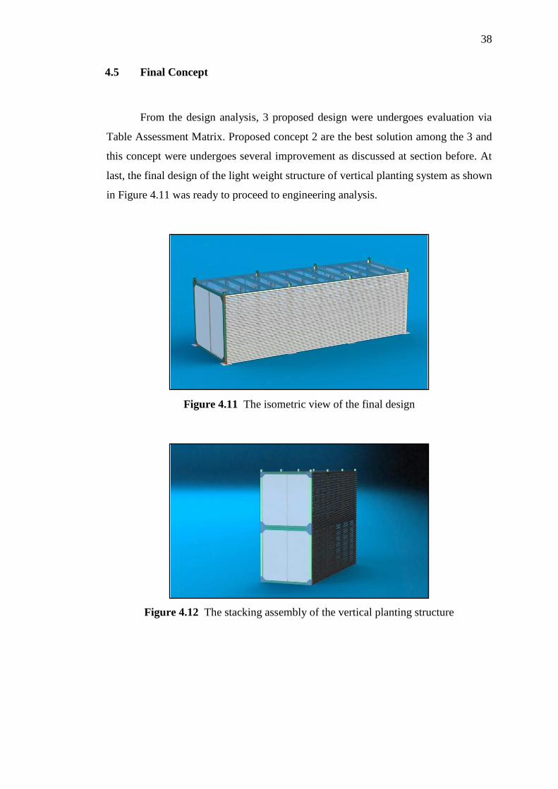
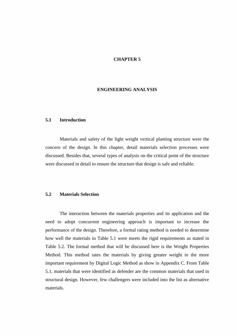
4.5 Final Concept
From the design analysis, 3 proposed design were undergoes evaluation via
Table Assessment Matrix. Proposed concept 2 are the best solution among the 3 and
this concept were undergoes several improvement as discussed at section before. At
last, the final design of the light weight structure of vertical planting system as shown
in Figure 4.11 was ready to proceed to engineering analysis.
Figure 4.11 The isometric view of the final design
Figure 4.12 The stacking assembly of the vertical planting structure
CHAPTER 5
ENGINEERING ANALYSIS
5.1 Introduction
Materials and safety of the light weight vertical planting structure were the
concern of the design. In this chapter, detail materials selection processes were
discussed. Besides that, several types of analysis on the critical point of the structure
were discussed in detail to ensure the structure that design is safe and reliable.
5.2 Materials Selection
The interaction between the materials properties and its application and the
need to adopt concurrent engineering approach is important to increase the
performance of the design. Therefore, a formal rating method is needed to determine
how well the materials in Table 5.1 were meets the rigid requirements as stated in
Table 5.2. The formal method that will be discussed here is the Weight Properties
Method. This method rates the materials by giving greater weight to the more
important requirement by Digital Logic Method as show in Appendix C. From Table
5.1, materials that were identified as defender are the common materials that used in
structural design. However, few challengers were included into the list as alternative
materials.
40
Table 5.1: Candidate Materials for Materials Selection Process
No Defenders Challengers
1 Aluminium 6061-T6 Glass Fibre Reinforced Polymer (E class fibre system)
2 Steel ASTM A36 Carbon Fibre Reinforced Polymer
3 Stainless Steel 304
Table 5.2: Rigid Requirement of the Materials Selection Process
No Rigid
Requirement Reason Objective
1 Yield Strength High strength for higher performance Maximum
2 Density Reduce the overall weight of the
structure Minimum
3 Cost Reduce materials cost Minimum
4 Corrosion
Resistance
Need to expose to weather and
corrosive environment Maximum
5 Carbon Dioxide
Burden
Parallel with the theory of Design For
Environment Minimum
From the calculation as attached in Appendix C, performance index of each
materials were shown in Table 5.3. The material with highest performance index (γ)
has been chosen as the most suitable material for the design requirement. By
referring to Table 5.3, it shows that Glass Fibre Reinforced Polymer (GFRP) has the
highest performance index compare to other candidate materials, which is 70.76. In
other words, GFRP appeared to be the most suitable materials for the light weight
vertical planting structure design.
Table 5.3: Performance Index (γ) of each candidate materials

41
5.3 Detail Computer Aided Drawing
Final design of the light weight structure for vertical planting system was
generated by using Computer Aided Design (CAD) – Solidworks. Each component
in the structure was drawn into three Dimensional (3D) modelling and converts it
into two Dimensional (2D) engineering drawing and attached in Appendix D. For
easy explanation in coming sections, each component was labelled as shown in
Figure 5.1 and Table 5.4.
Figure 5.1 Vertical planting structure components
Table 5.4: Bill of Materials
ITEM NO. PART NUMBER QUANTITY
1 Box Beam 102x102x6.4 (2398) 38
2 Box Column 102x102x6.4 (2500) 8
3 Angle Connector 96
4 Corner Joint Plate 16
5 Middle Joint Plate 8
6 Preferred Wide FW 0.375 640
7 HNUT 0.375-24-D-N 320
8 Hex Bolt-ai 320
42
5.4 Engineering Analysis
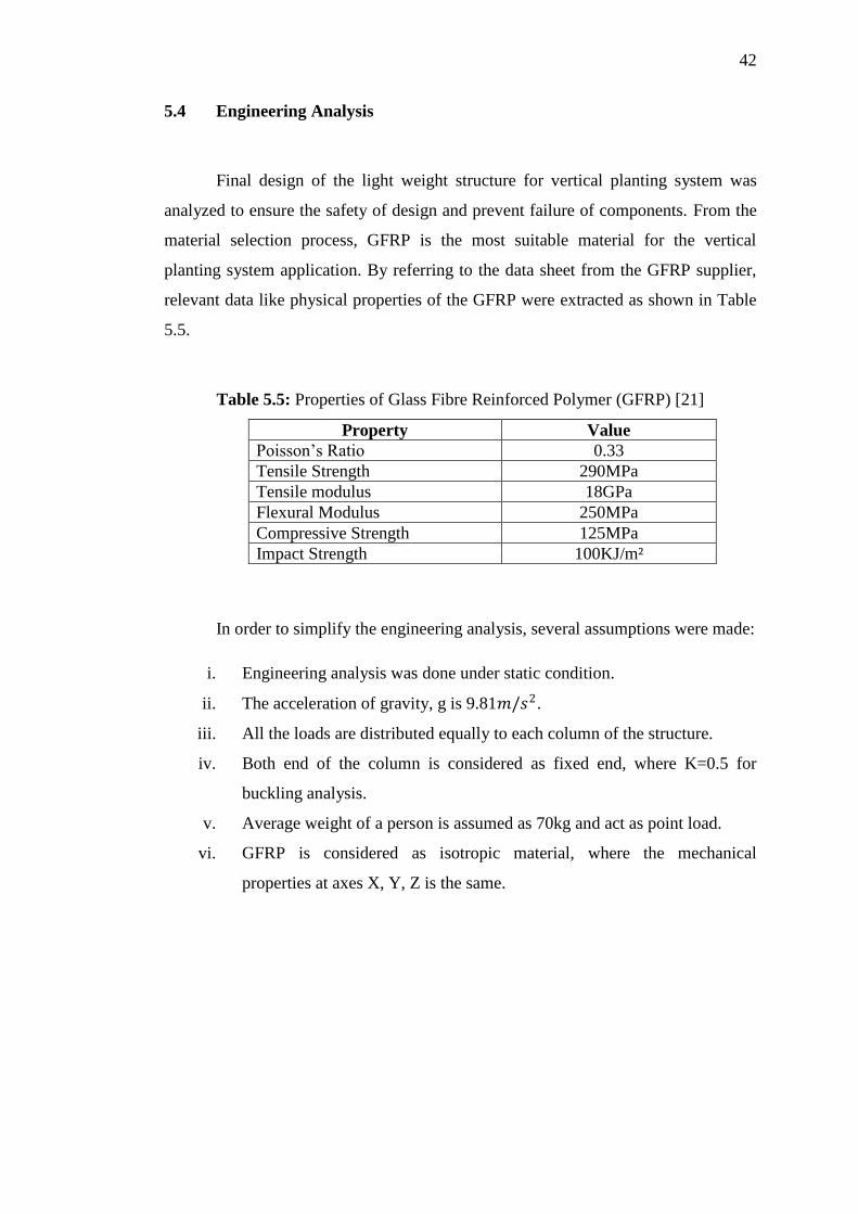
Final design of the light weight structure for vertical planting system was
analyzed to ensure the safety of design and prevent failure of components. From the
material selection process, GFRP is the most suitable material for the vertical
planting system application. By referring to the data sheet from the GFRP supplier,
relevant data like physical properties of the GFRP were extracted as shown in Table
5.5.
Table 5.5: Properties of Glass Fibre Reinforced Polymer (GFRP) [21]
Property Value
Poisson’s Ratio 0.33
Tensile Strength 290MPa
Tensile modulus 18GPa
Flexural Modulus 250MPa
Compressive Strength 125MPa
Impact Strength 100KJ/m²
In order to simplify the engineering analysis, several assumptions were made:
i. Engineering analysis was done under static condition.
ii. The acceleration of gravity, g is 9.81𝑚/𝑠2.
iii. All the loads are distributed equally to each column of the structure.
iv. Both end of the column is considered as fixed end, where K=0.5 for
buckling analysis.
v. Average weight of a person is assumed as 70kg and act as point load.
vi. GFRP is considered as isotropic material, where the mechanical
properties at axes X, Y, Z is the same.
43
5.4.1 Loading Define
Total load of the structure was divided into two categories, which were dead
load and live load. Dead load refers to the weight that remain unchanged or the
weight that caused by the structure itself, it can comes from the weight of the
component, hydroponic system, bolts, nuts, and others. On the other hands, the live
load refers to the weight like human weight, water, and vegetables weight that is not
constant. For engineering analysis, the total of dead load and live load were used as
the critical load that acts toward the structure. From the estimation from Solidworks
and the calculation as attached in Appendix E, the total load of each unit of vertical
planting structure is 1924.20kg, which equivalent to 18876.38N.
5.4.2 Stress Analysis
All the components in the vertical planting structure were analyzed based on
two failure theories, which were Maximum-Normal-Stress Theory and Distortion
Energy Theory. Maximum-Normal-Stress is suitable to apply for all brittle materials
where failure occurs whenever one of the three principles stresses equals or larger
than the strength of materials [22]. However, Distortion Energy Theory is suitable
for ductile materials where yielding occurs when the distortion strain energy per unit
volume reaches or exceeds the limit in simple tension or compression on the same
materials [22].
In stress analysis, the weight of the structure will act as load to the base
structure. The entire load was distributed to the box column of the vertical planting
structure equally. Two types of stress analysis were done on the vertical planting
structure, which were tensile analysis and compression analysis.
44
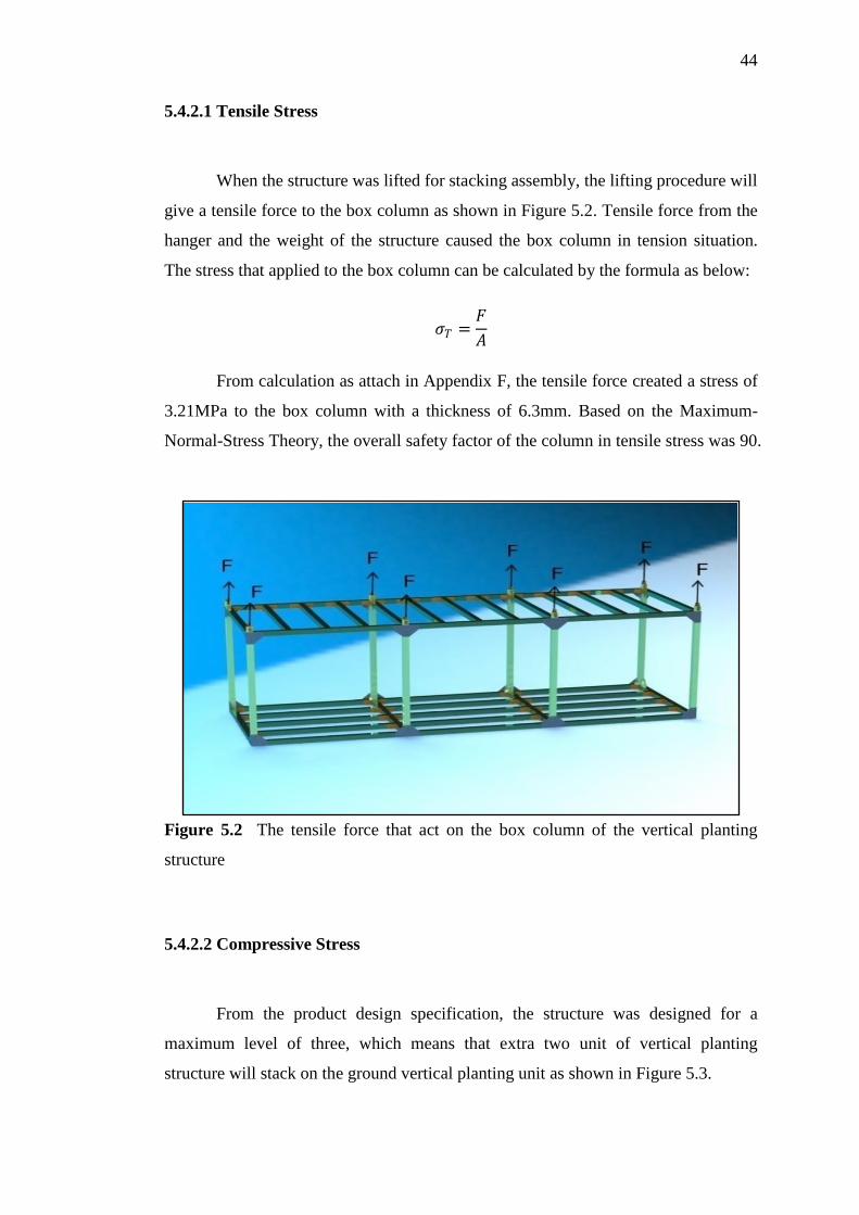
5.4.2.1 Tensile Stress
When the structure was lifted for stacking assembly, the lifting procedure will
give a tensile force to the box column as shown in Figure 5.2. Tensile force from the
hanger and the weight of the structure caused the box column in tension situation.
The stress that applied to the box column can be calculated by the formula as below:
𝜎𝑇 =𝐹
𝐴
From calculation as attach in Appendix F, the tensile force created a stress of
3.21MPa to the box column with a thickness of 6.3mm. Based on the Maximum-
Normal-Stress Theory, the overall safety factor of the column in tensile stress was 90.
Figure 5.2 The tensile force that act on the box column of the vertical planting
structure
5.4.2.2 Compressive Stress
From the product design specification, the structure was designed for a
maximum level of three, which means that extra two unit of vertical planting
structure will stack on the ground vertical planting unit as shown in Figure 5.3.
45
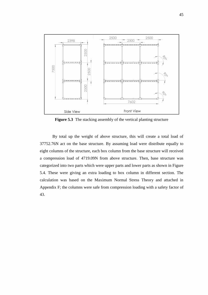
Figure 5.3 The stacking assembly of the vertical planting structure
By total up the weight of above structure, this will create a total load of
37752.76N act on the base structure. By assuming load were distribute equally to
eight columns of the structure, each box column from the base structure will received
a compression load of 4719.09N from above structure. Then, base structure was
categorized into two parts which were upper parts and lower parts as shown in Figure
5.4. These were giving an extra loading to box column in different section. The
calculation was based on the Maximum Normal Stress Theory and attached in
Appendix F; the columns were safe from compression loading with a safety factor of
43.
46
Figure 5.4 The upper and lower parts of the vertical planting structure
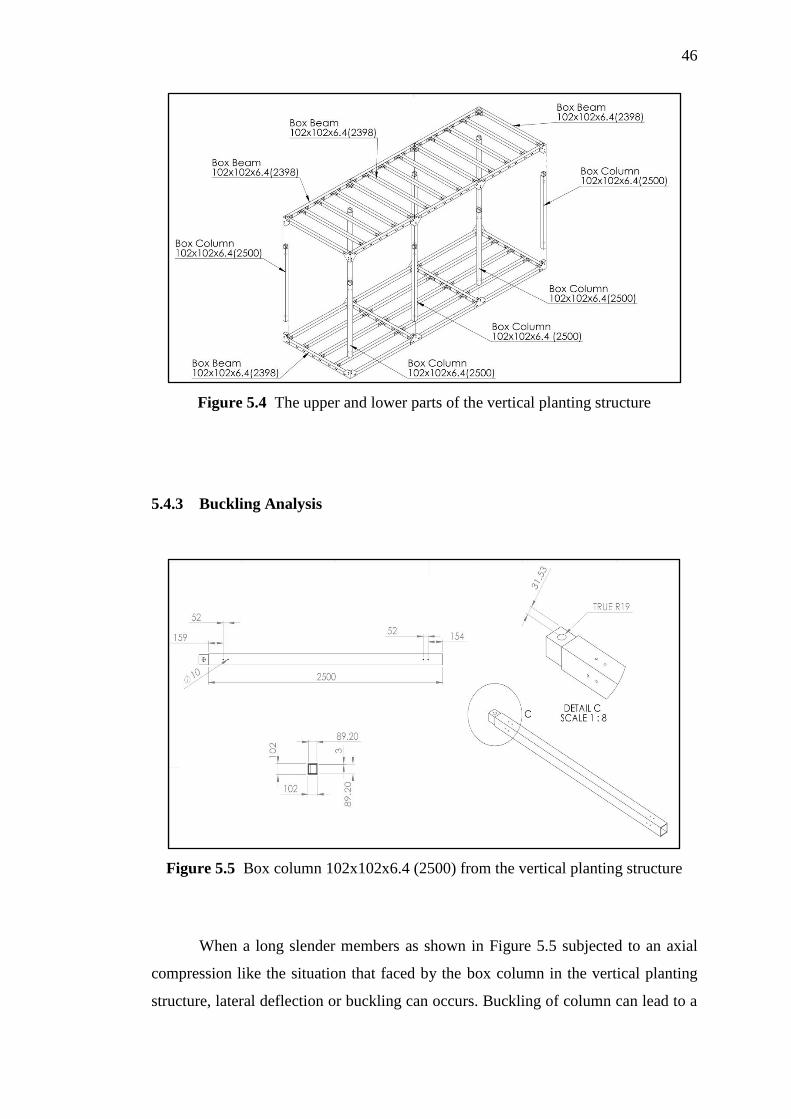
5.4.3 Buckling Analysis
Figure 5.5 Box column 102x102x6.4 (2500) from the vertical planting structure
When a long slender members as shown in Figure 5.5 subjected to an axial
compression like the situation that faced by the box column in the vertical planting
structure, lateral deflection or buckling can occurs. Buckling of column can lead to a

47
sudden failure of a structure. Critical axial load of the box column can be calculated
by the formula as below:
𝑃𝑐𝑟 =𝜋2𝐸𝐼
(𝐾𝐿)2
From the calculation as attached in Appendix G, the maximum load that can
apply to the box column before buckling was 186.48kN, which equivalent to
76.2MPa. Since the critical stress of the box column was smaller than the yield stress,
it is conclude that the box column will only failed by buckling before the
compression. Based on Maximum Normal Stress Theory, the safety factor of the
column in the vertical planting structure was 26.
5.4.4 Deflection and Displacement Analysis
The allowable deflection and displacement of beam was set in less than 5mm
and 2mm respectively. Box beams as shown in Figure 5.6 were undergoes deflection
analysis and box columns as shown in Figure 5.5 were undergoes displacement
analysis. As attached in Appendix H, it was assumed that the box beam was applied
with a load of a human with 70kg in the centre of beam. Maximum deflection
happened at the centre of beam with a maximum deflection of 2.3mm which was
within the specifications. A further analysis was done to the beam with a dimension
of 76mm x76mm, the results shown the deflections of this type of beam was out of
specification which is 5.93mm. As the result, the beam of size 76mm x 76mm was
not suitable for this structure. Thus, beam with size of 102mm x 102mm was chosen.
The displacement analysis was carried out for the box column. Displacement
of the box column can be calculated by the formula as below:
𝛿 = ∑𝑃𝐿
𝐴𝐸

48
By dividing the box column into few sections as the attachment in Appendix
I, the total displacement of the column was 2.96𝑥10−4𝑚 which is within the
specification of less than 2mm.
Figure 5.6 Box beam 102x102x6.4 (2398) from the vertical planting structure
5.4.5 Bolt and Member Analysis
There were two types of joint in the vertical planting structure as shown in
Figure 5.7. Each component was connected together by bolts and nuts. From the bolt
analysis in Appendix J, the austenite stainless steel bolt with a diameter of 5mm and
coarse-pitch was chosen initially. The bolts had a safety factor of 18 by applying
Distortion Energy Theory. However, from the calculation that attached in Appendix
K, the bolt with 5mm diameter was created a shear load of 55.15MPa to the corner
joint plate. By this, the safety factor of the plate was 2, which was too low.
In order to increase the safety factor of plate, the increase of the area of stress
is one of the solutions. The area of stress was increased by increasing the diameter of
bolt to 10mm. By this, the shear stress was reduced to 27.6MPa and the safety factor
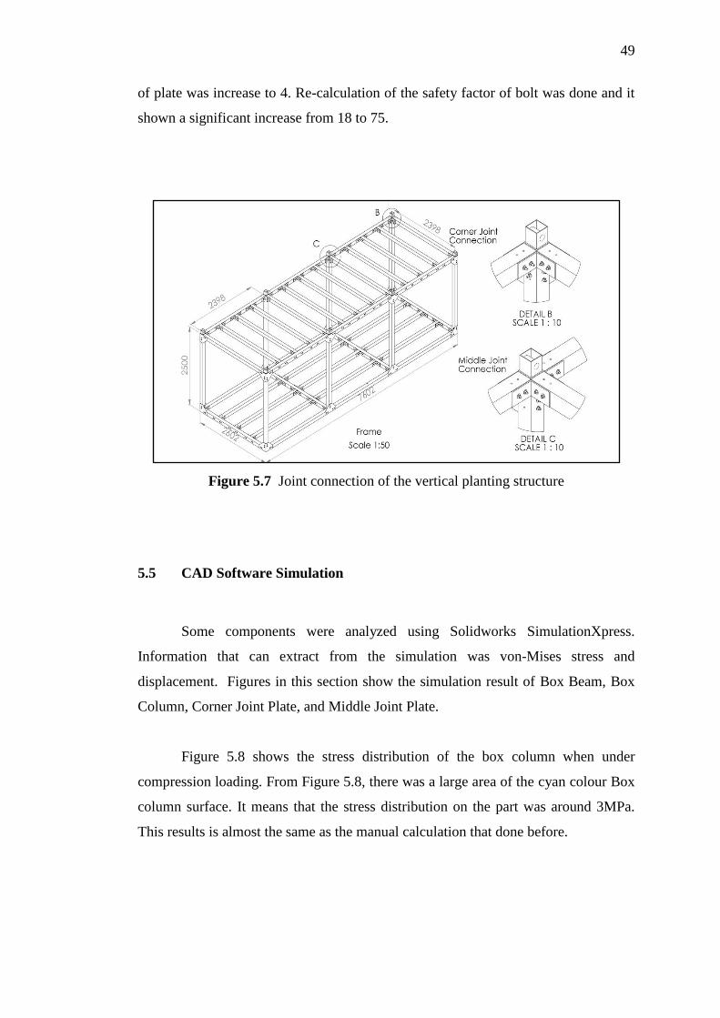
49
of plate was increase to 4. Re-calculation of the safety factor of bolt was done and it
shown a significant increase from 18 to 75.
Figure 5.7 Joint connection of the vertical planting structure
5.5 CAD Software Simulation
Some components were analyzed using Solidworks SimulationXpress.
Information that can extract from the simulation was von-Mises stress and
displacement. Figures in this section show the simulation result of Box Beam, Box
Column, Corner Joint Plate, and Middle Joint Plate.
Figure 5.8 shows the stress distribution of the box column when under
compression loading. From Figure 5.8, there was a large area of the cyan colour Box
column surface. It means that the stress distribution on the part was around 3MPa.
This results is almost the same as the manual calculation that done before.

50
Figure 5.8 The stress distribution of lower part of box column while under
compression loading
Figure 5.9 shows a tensile loading of the box column when the structure was
lifted to a higher place. From the Figure 5.9, the area that in orange colour indicates
the highest stress distribution. The highest tensile stress that obtained from the
simulation was around 4MPa, which is almost the same as the result from manual
calculation.
Figure 5.9 The stress distribution of the top part of box column while under tensile
loading

51
Figure 5.10 shows the displacement of the column when under compression
loading. The displacement was the largest on the top section of the column, which
the area was shown in red colour. The maximum displacement of the column from
this simulation was around 0.23mm, which was exactly the same as the manual
calculation.
Figure 5.11 shows the deflection of beam when a point load of 70kg act at the
centre of beam. From the Figure 5.11, it shows that maximum deflection happens at
the centre of beam where the area of beam is in red colour. The maximum deflection
of beam that got from simulation was 0.9mm. This value is different from the manual
calculation. The reason behind it was the different assumptions were made during the
analysis. The beam was assumed as simply supported beam in manual calculation,
but cantilever beam (Fixed end) during the simulation.
Figure 5.10 Displacement of box column while under compression loading

52
Figure 5.11 Deflection of box beam while under a point load condition
Figure 5.12 The stress distribution of corner joint plate
Figure 5.12 shows the stress distribution of corner joint plate when loading
applied on it. The load was come from the bolts and box beam. From the Figure 5.12,
the area that in green colour indicated the high stress area. From the indicator on the
right hand side of the figure, the green colour represents a stress of around 25MPa.
This value was almost the same as result from manual calculation.
53
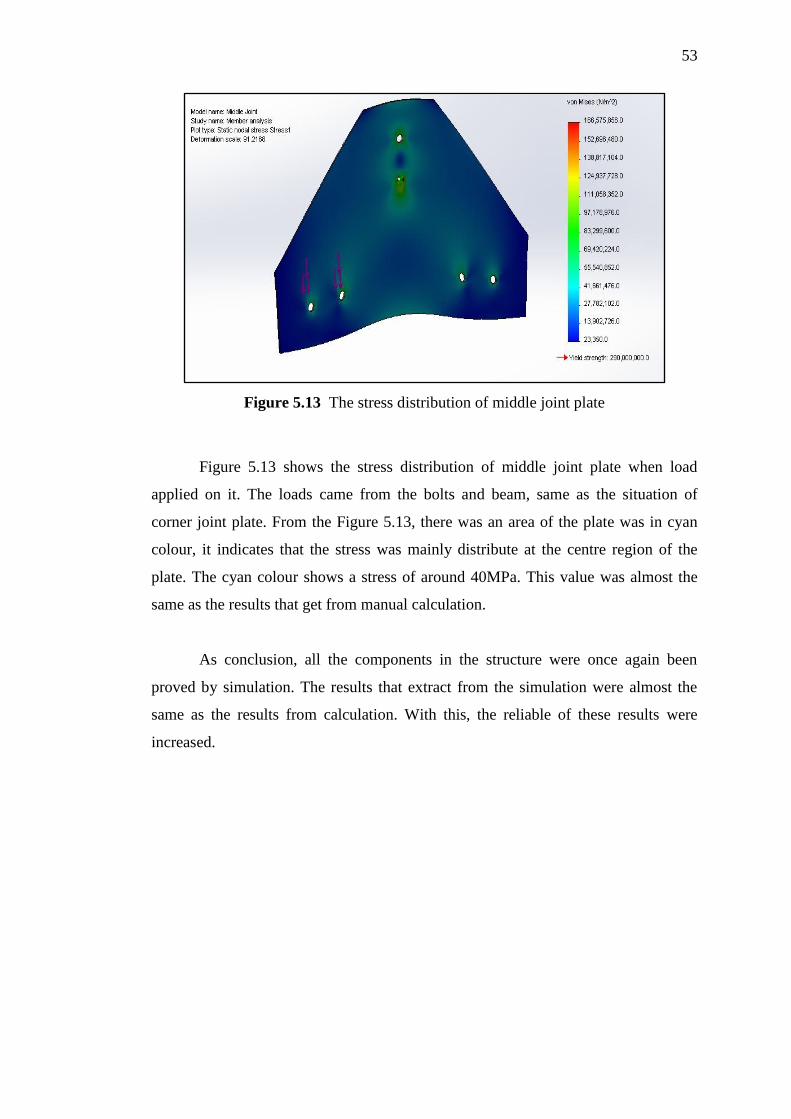
Figure 5.13 The stress distribution of middle joint plate
Figure 5.13 shows the stress distribution of middle joint plate when load
applied on it. The loads came from the bolts and beam, same as the situation of
corner joint plate. From the Figure 5.13, there was an area of the plate was in cyan
colour, it indicates that the stress was mainly distribute at the centre region of the
plate. The cyan colour shows a stress of around 40MPa. This value was almost the
same as the results that get from manual calculation.
As conclusion, all the components in the structure were once again been
proved by simulation. The results that extract from the simulation were almost the
same as the results from calculation. With this, the reliable of these results were
increased.

CHAPTER 6
CONCLUSION AND RECOMMENDATIONS
6.1 Conclusion
As conclusion, a structure for vertical planting system was proposed. Besides
the light weight as the main characteristic of the vertical structure, the structure was
design into portable and assembles. Each vertical planting structure can assemble to
form a larger farm. By this vertical planting system, the growing of vegetables can be
done within a smaller area compare to conventional farming method. By this, the
vertical planting structure can reduce the impact of agriculture to environment.
Besides that, this innovation can maximize the yield of vegetables without increase
the burden to the environment.
The vertical planting structure was design parallel to the theory of Design for
Environment. Design for Energy and Material Conservation is one of the sub-topics
in the theory of Design for Environment. From this topic, utilizing fewer resources to
deliver equivalent or greater performance and increase the product service life can
reduce the usage of materials and energy. In this vertical planting structure, the main
material of the structure was Glass Fibre Reinforced Polymer (GFRP) with offer an
extra long usage life and higher performance to normal structural alloys as stated in
the theory of Design for Environment.
55
6.2 Recommendations
The design of light weight structure of vertical planting system can be further
improved. The recommendations for further studies are:-
i. Improvement on joining method for the vertical planting structure.
ii. Improvement on the structure for the wider application of more
species of plants like fruiting vegetables, legumes or fruits.
iii. Further development of piping and electrical circuit for the vertical
planting structure like rain water harvesting system and renewable
energy system.
56
REFERENCES
1. Rohaniza Idris. (2012, Jan 29). Ladang Langit. Berita Minggu, p.1 -3.
2. Ooi. (2011). Making Efforts In Sustainability Count. Jurutera, 11, 6 -10.
3. Sustained supply-Keeping it under control. (2010, May 12). The Star. p.1.
4. Kementerian Pertanian & Industri Asas Tani Malaysia, Empat Faktor Tangani
Cabaran Bekalan Makanan,2012
<http://www.moa.gov.my/web/guest/4cabaran_bekalanmakanan>, (Retrieved
December 7, 2012)
5. Malaysia belanja RM92j sehari import makanan. (2012, July 13). Berita Harian.
p.19.
6. Ministry of Agriculture and Agro-based Industry, Malaysia. Agrofood Statistics
2011. Malaysia: Strategic Planning and international Division. 2012
7. Metra Syahril Mohamed. (2012, July 13). Import makanan cecah RM92j sehari.
Utusan Malaysia. p.26.
8. Wealth Creation On Agriculture Innovation. (2012, August 10). Business and
Financial. p.58-60.
9. Components, C. o. E. T. f. U. L.-C. E. o. S., C. o. Engineering, et al. (1991).
Enabling Technologies for Unified Life-Cycle Engineering of Structural
Components. Washington, DC: The National Academies Press.
10. John R. Hartley. Concurrent Engineering: Shortening Lead Times, Raising
Quality, and Lowering Costs. Portland, Oregon: Productivity Press. 1992
11. Salzberg. S and Watkins. M. Managing information for concurrent engineering:
challenges and barriers. In S. Culley. Research in Engineering Design. London:
Springer-Verlag. 35-52; 1990
12. K.L. Edwards. (2003). Towards more strategic product design for manufacture
and assembly: priorities for concurrent engineering. Materials and Design; 23:
61-656
13. Joseph Fiksel. Design for Environment. 2nd
ed. New York: McGraw-Hill. 2012
57
14. Stewart Kenyon. Hydroponics for the Home Gardener. Canada: Key Porter
Books. 1992
15. Discovery Hydroponics
<http://discoverhydroponics.com/wp-content/uploads/2011/03/Aeroponics-
Squash.jpg>, (Retrieved December 8, 2012)
16. Aquaponiceaay.com
<http://aquaponicseasy.com/images%20for%20aquaponics/deepwater%20culture
%20or%20raft%20system%20aquaponics.jpg>, (Retrieved December 7, 2012)
17. Time Magazine, Vertical Farming
<http://www.time.com/time/magazine/article/0,9171,1865974,00.html>,
(Retrieved December 8, 2012)
18. Aerofarm
<http://aerofarms.com/why/technology/>, (Retrieved December 3, 2012)
19. Tower Garden
<https://www.towergarden.com/online-store/tower-garden-growing-system>,
(Retrieved December 3, 2012)
20. Reinhold Ziegler (2005).Vertical Aeroponic Growing System. Synergy
International Inc.
21. Dura Composites Ltd (2009) Fiberglass Pultruded Sections: Dura profile
[Brochure]. United Kingdom: Dura Composites
22. Richard Budynas and Keith Nisbett. Shigley’s Mechanical Engineering Design.
6th
ed. New York: McGraw-Hill. 2011
Appendix A
Product Design Specifications 58
1. User
The system shall target entrepreneur as customer (money is not a constraint
as long term investment)
2. Farming Technique
The technique used in the system must be soilless (hydroponic)
3. Types of Vegetables
The system should can plant leafy vegetable, Brassicas or herbs
4. Weather
The system can cope with the Malaysia’s weather like sunny, raining, and
windy season.
5. Geography
The system should suitable with majority agriculture’s land condition (Hill,
mountain, flat, and valley) in peninsular of Malaysia.
The system should suitable with the Malaysia soil condition (sandy, muddy,
rock, soil)
6. Structure
The structure must be able to built for 1 floor or maximum of 3 floors
The structure must be in modular form, which can be used a single unit or
many unit for high yield.
7. Loading
The structure must be able withstand torsion, tension, bending moment, shear,
and buckling
Each component must be safe. (Safety factor > 3)
The displacement of the component must small (Displacement < 2mm)
8. Joint
The joining of each components must be mechanical joint
The assembly and disassembly process must be easy, which can be done by 3
or less people.
9. Ergonomic
The weight of each component must be able carry by a human
The height of each floor must be able to fit a human height
The in the structure must be large enough for a human to move

Appendix A
Product Design Specifications 59
The working environment in the structure must be safe for human.
10. Materials
The material that used should be corrosion resistance
The material must be able to withstand high loads
The material must be able withstand the UV light
11. Shape
The shape of the parts should be high efficiency (Weight to load ratio)
12. Accessories
The components that design should have a space for accessories installation
(piping and electrical wire)
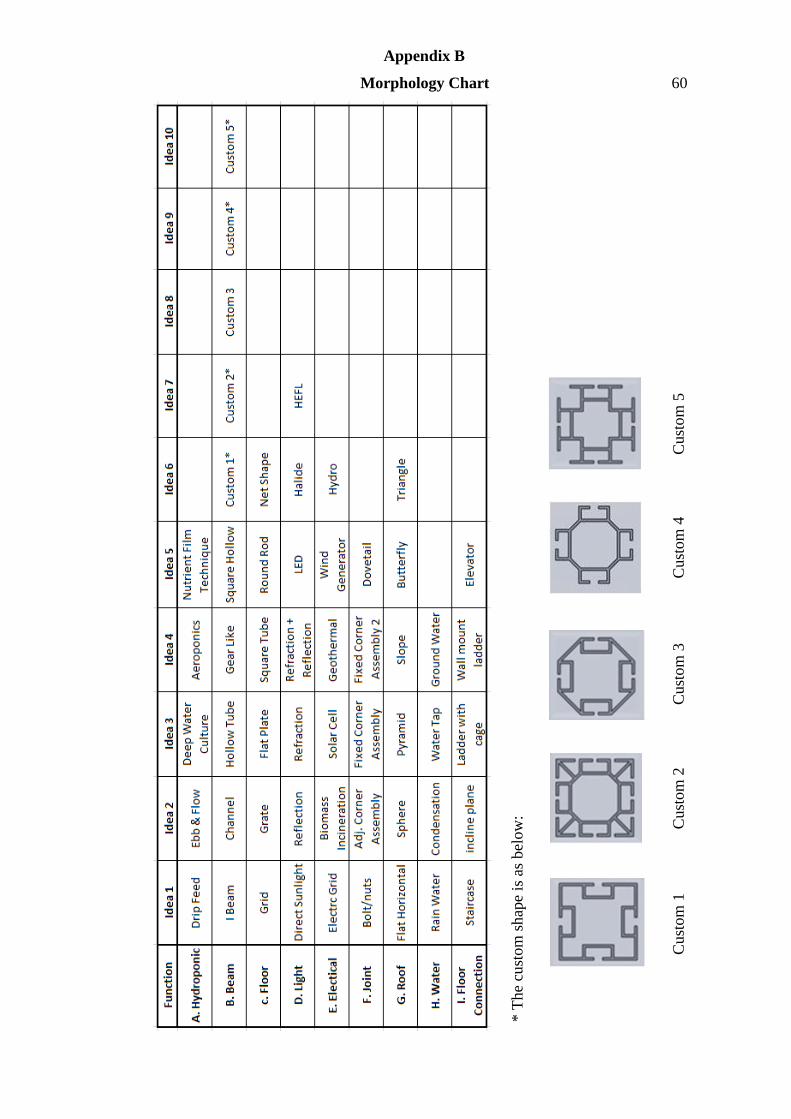
Appendix B
Morphology Chart 60
* T
he
cust
om
shap
e is
as
bel
ow
:
Cust
om
1
Cust
om
2
Cust
om
3
Cust
om
4
Cust
om
5
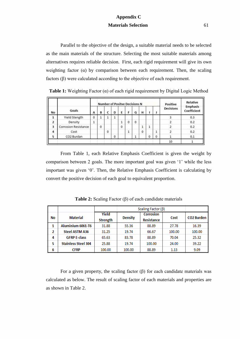
Appendix C
Materials Selection 61
Parallel to the objective of the design, a suitable material needs to be selected
as the main materials of the structure. Selecting the most suitable materials among
alternatives requires reliable decision. First, each rigid requirement will give its own
weighting factor (α) by comparison between each requirement. Then, the scaling
factors (β) were calculated according to the objective of each requirement.
Table 1: Weighting Factor (α) of each rigid requirement by Digital Logic Method
From Table 1, each Relative Emphasis Coefficient is given the weight by
comparison between 2 goals. The more important goal was given ‘1’ while the less
important was given ‘0’. Then, the Relative Emphasis Coefficient is calculating by
convert the positive decision of each goal to equivalent proportion.
Table 2: Scaling Factor (β) of each candidate materials
For a given property, the scaling factor (β) for each candidate materials was
calculated as below. The result of scaling factor of each materials and properties are
as shown in Table 2.

Appendix C
Materials Selection 62
For properties with the objective of maximum requirement:
𝛽 =𝑛𝑢𝑚𝑒𝑟𝑖𝑐𝑎𝑙 𝑣𝑎𝑙𝑢𝑒 𝑜𝑓 𝑝𝑟𝑜𝑝𝑒𝑟𝑡𝑦
𝑀𝑎𝑥𝑖𝑚𝑢𝑚 𝑣𝑎𝑙𝑢𝑒 𝑖𝑛 𝑡ℎ𝑒 𝑙𝑖𝑠𝑡𝑥100
For properties with the objective of minimum requirement:
𝛽 =𝐿𝑜𝑤𝑒𝑠𝑡 𝑣𝑎𝑙𝑢𝑒 𝑖𝑛 𝑡ℎ𝑒 𝑙𝑖𝑠𝑡
𝑁𝑢𝑚𝑒𝑟𝑖𝑐𝑎𝑙 𝑣𝑎𝑙𝑢𝑒 𝑜𝑓 𝑝𝑟𝑜𝑝𝑒𝑟𝑡𝑦𝑥100
At the end of the materials selection process, the performance index (γ) of
each material was calculated by the formula as below:
𝛾 = ∑𝛼𝛽
Table 3: Performance Index (γ)
As conclusion, the material with highest performance index is the selected
material which fulfill the requirement the most. From Table 3, the GFRP is the most
suitable material for the design of light weight structure for vertical planting system.
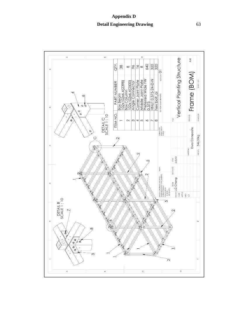
Appendix D
Detail Engineering Drawing 63

Appendix D
Detail Engineering Drawing 64
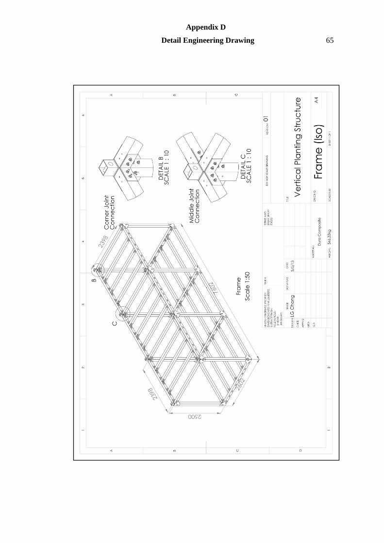
Appendix D
Detail Engineering Drawing 65
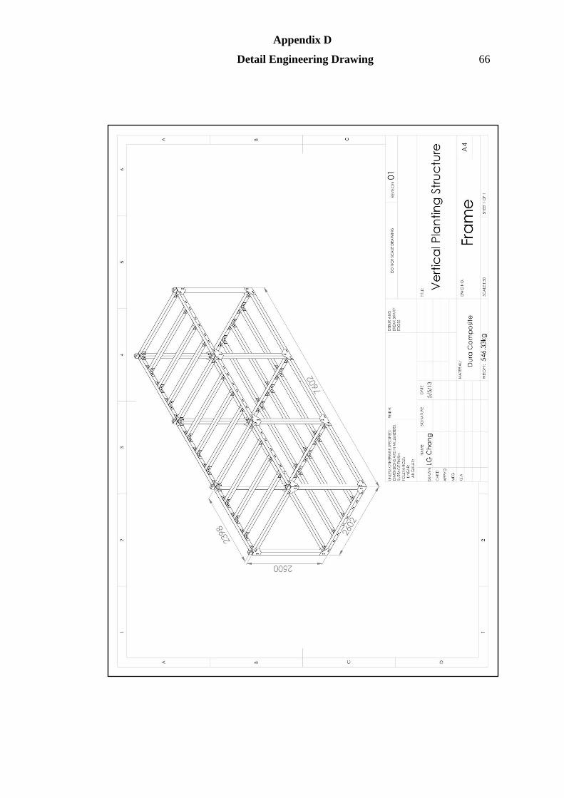
Appendix D
Detail Engineering Drawing 66
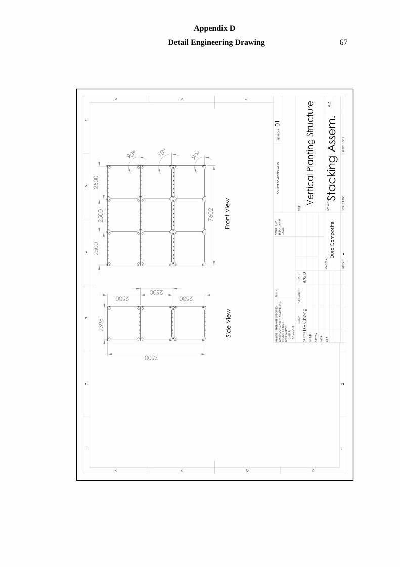
Appendix D
Detail Engineering Drawing 67
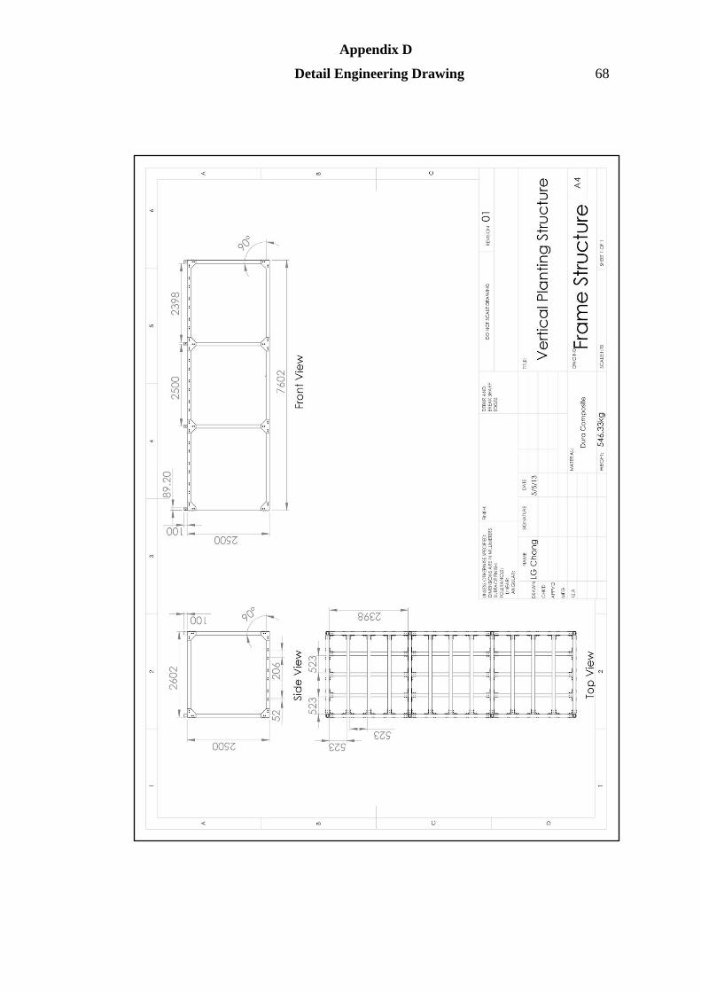
Appendix D
Detail Engineering Drawing 68
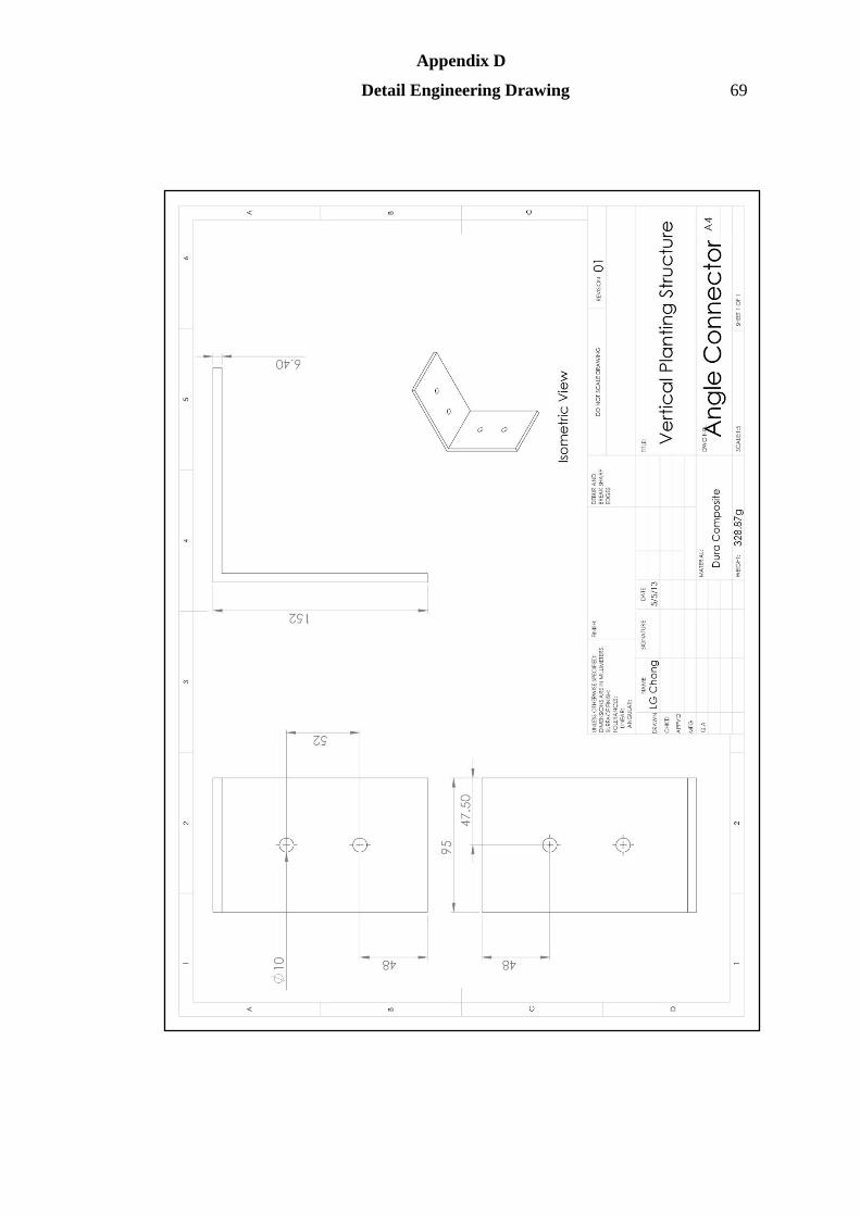
Appendix D
Detail Engineering Drawing 69
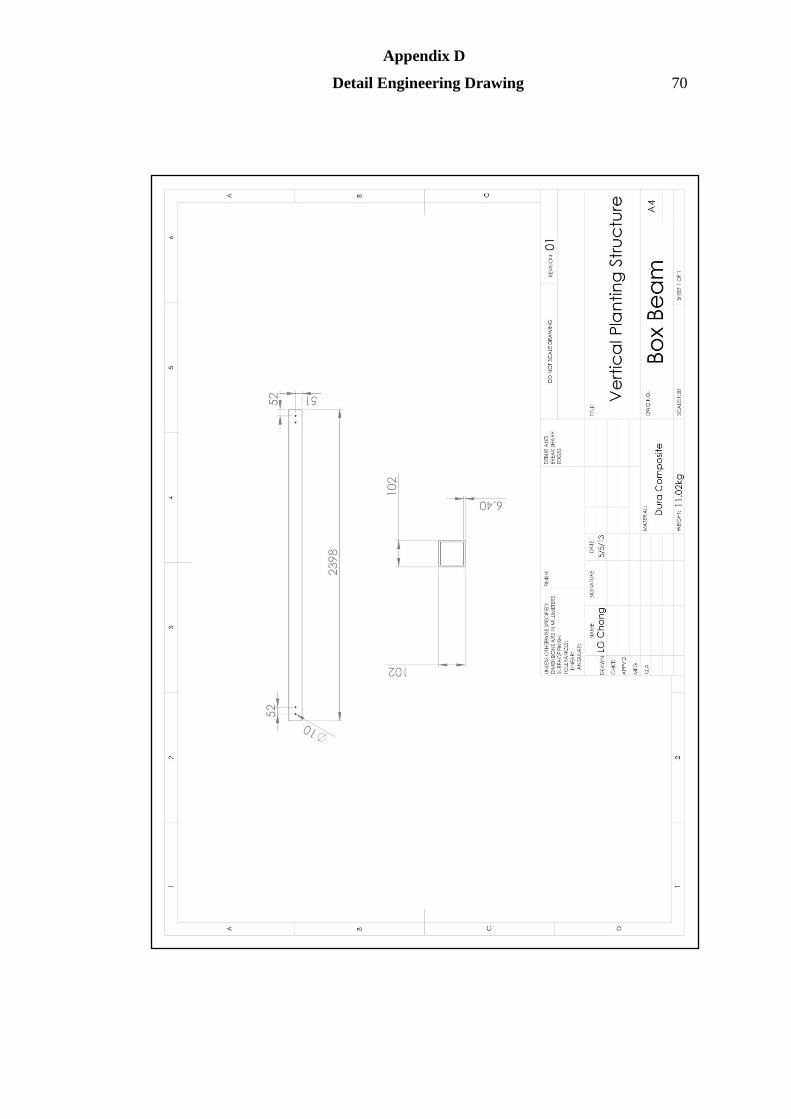
Appendix D
Detail Engineering Drawing 70
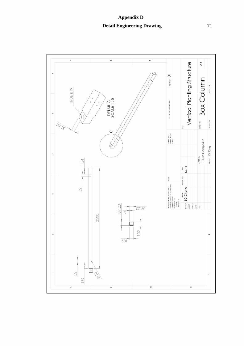
Appendix D
Detail Engineering Drawing 71

Appendix D
Detail Engineering Drawing 72
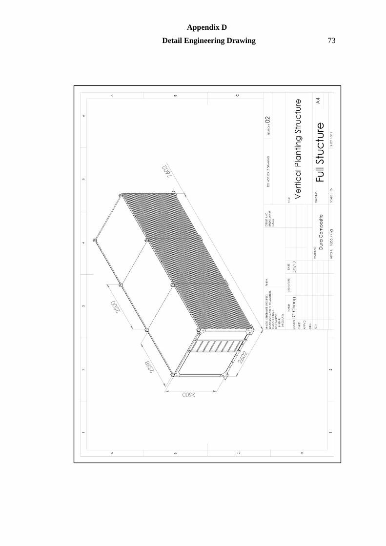
Appendix D
Detail Engineering Drawing 73
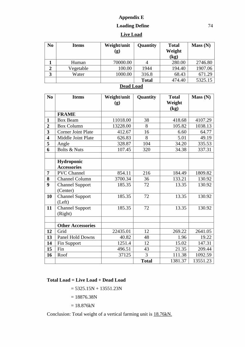
Appendix E
Loading Define 74
Live Load
No Items Weight/unit
(g)
Quantity Total
Weight
(kg)
Mass (N)
1 Human 70000.00 4 280.00 2746.80
2 Vegetable 100.00 1944 194.40 1907.06
3 Water 1000.00 316.8 68.43 671.29
Total 474.40 5325.15
Dead Load
No Items Weight/unit
(g)
Quantity Total
Weight
(kg)
Mass (N)
FRAME
1 Box Beam 11018.00 38 418.68 4107.29
2 Box Column 13228.00 8 105.82 1038.13
3 Corner Joint Plate 412.67 16 6.60 64.77
4 Middle Joint Plate 626.83 8 5.01 49.19
5 Angle 328.87 104 34.20 335.53
6 Bolts & Nuts 107.45 320 34.38 337.31
Hydroponic
Accessories
7 PVC Channel 854.11 216 184.49 1809.82
8 Channel Column 3700.34 36 133.21 130.92
9 Channel Support
(Center)
185.35 72 13.35 130.92
10 Channel Support
(Left)
185.35 72 13.35 130.92
11 Channel Support
(Right)
185.35 72 13.35 130.92
Other Accessories
12 Grid 22435.01 12 269.22 2641.05
13 Panel Hold Downs 40.82 48 1.96 19.22
14 Fin Support 1251.4 12 15.02 147.31
15 Fin 496.51 43 21.35 209.44
16 Roof 37125 3 111.38 1092.59
Total 1381.37 13551.23
Total Load = Live Load + Dead Load
= 5325.15N + 13551.23N
= 18876.38N
= 18.876kN
Conclusion: Total weight of a vertical farming unit is 18.76kN.
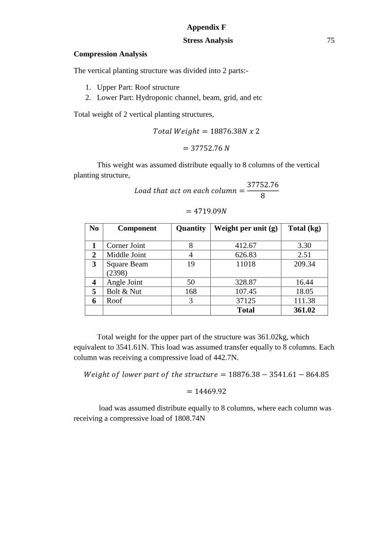
Appendix F
Stress Analysis 75
Compression Analysis
The vertical planting structure was divided into 2 parts:-
1. Upper Part: Roof structure
2. Lower Part: Hydroponic channel, beam, grid, and etc
Total weight of 2 vertical planting structures,
𝑇𝑜𝑡𝑎𝑙 𝑊𝑒𝑖𝑔𝑡 = 18876.38𝑁 𝑥 2
= 37752.76 𝑁
This weight was assumed distribute equally to 8 columns of the vertical
planting structure,
𝐿𝑜𝑎𝑑 𝑡𝑎𝑡 𝑎𝑐𝑡 𝑜𝑛 𝑒𝑎𝑐 𝑐𝑜𝑙𝑢𝑚𝑛 =37752.76
8
= 4719.09𝑁
No Component Quantity Weight per unit (g) Total (kg)
1 Corner Joint 8 412.67 3.30
2 Middle Joint 4 626.83 2.51
3 Square Beam
(2398)
19 11018 209.34
4 Angle Joint 50 328.87 16.44
5 Bolt & Nut 168 107.45 18.05
6 Roof 3 37125 111.38
Total 361.02
Total weight for the upper part of the structure was 361.02kg, which
equivalent to 3541.61N. This load was assumed transfer equally to 8 columns. Each
column was receiving a compressive load of 442.7N.
𝑊𝑒𝑖𝑔𝑡 𝑜𝑓 𝑙𝑜𝑤𝑒𝑟 𝑝𝑎𝑟𝑡 𝑜𝑓 𝑡𝑒 𝑠𝑡𝑟𝑢𝑐𝑡𝑢𝑟𝑒 = 18876.38 − 3541.61 − 864.85
= 14469.92
load was assumed distribute equally to 8 columns, where each column was
receiving a compressive load of 1808.74N
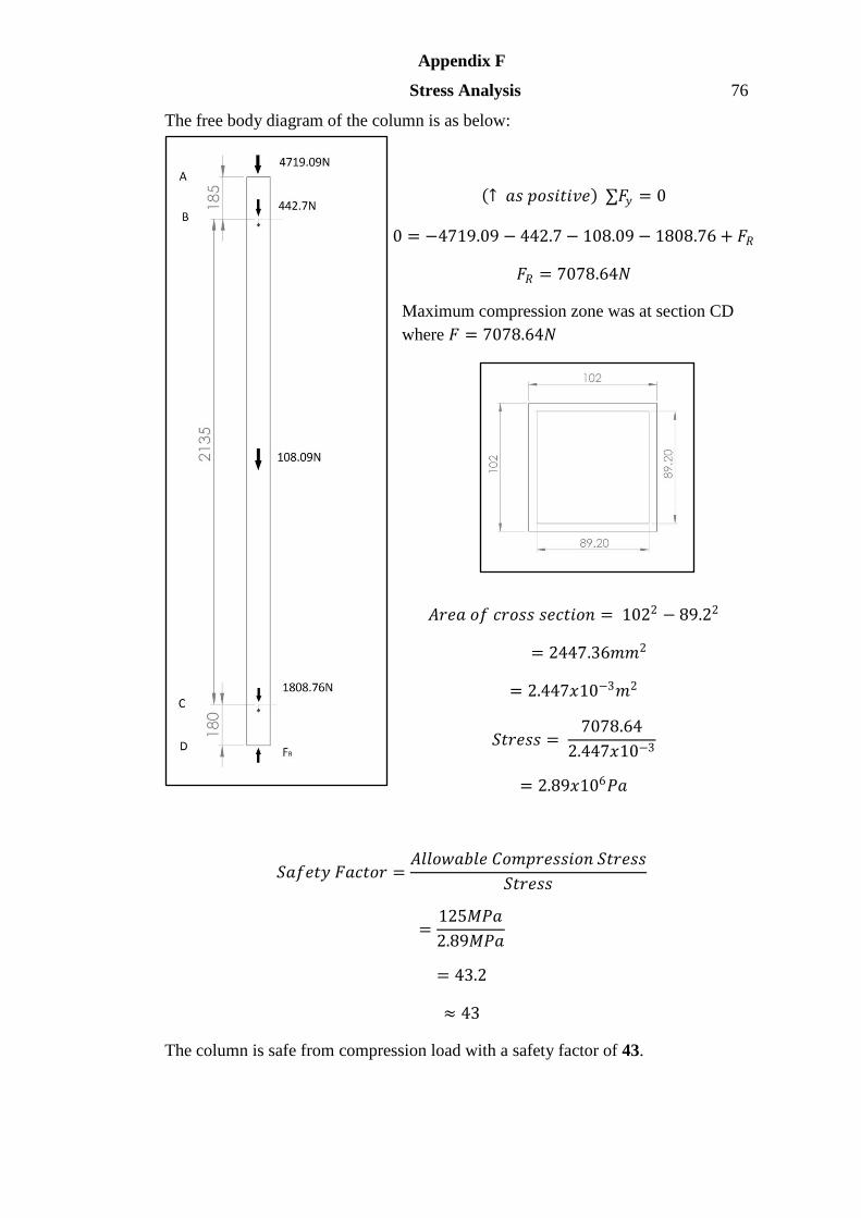
Appendix F
Stress Analysis 76
The free body diagram of the column is as below:
↑ 𝑎𝑠 𝑝𝑜𝑠𝑖𝑡𝑖𝑣𝑒 ∑𝐹𝑦 = 0
0 = −4719.09 − 442.7 − 108.09 − 1808.76 + 𝐹𝑅
𝐹𝑅 = 7078.64𝑁
Maximum compression zone was at section CD
where 𝐹 = 7078.64𝑁
𝐴𝑟𝑒𝑎 𝑜𝑓 𝑐𝑟𝑜𝑠𝑠 𝑠𝑒𝑐𝑡𝑖𝑜𝑛 = 1022 − 89.22
= 2447.36𝑚𝑚2
= 2.447𝑥10−3𝑚2
𝑆𝑡𝑟𝑒𝑠𝑠 = 7078.64
2.447𝑥10−3
= 2.89𝑥106𝑃𝑎
𝑆𝑎𝑓𝑒𝑡𝑦 𝐹𝑎𝑐𝑡𝑜𝑟 =𝐴𝑙𝑙𝑜𝑤𝑎𝑏𝑙𝑒 𝐶𝑜𝑚𝑝𝑟𝑒𝑠𝑠𝑖𝑜𝑛 𝑆𝑡𝑟𝑒𝑠𝑠
𝑆𝑡𝑟𝑒𝑠𝑠
=125𝑀𝑃𝑎
2.89𝑀𝑃𝑎
= 43.2
≈ 43
The column is safe from compression load with a safety factor of 43.
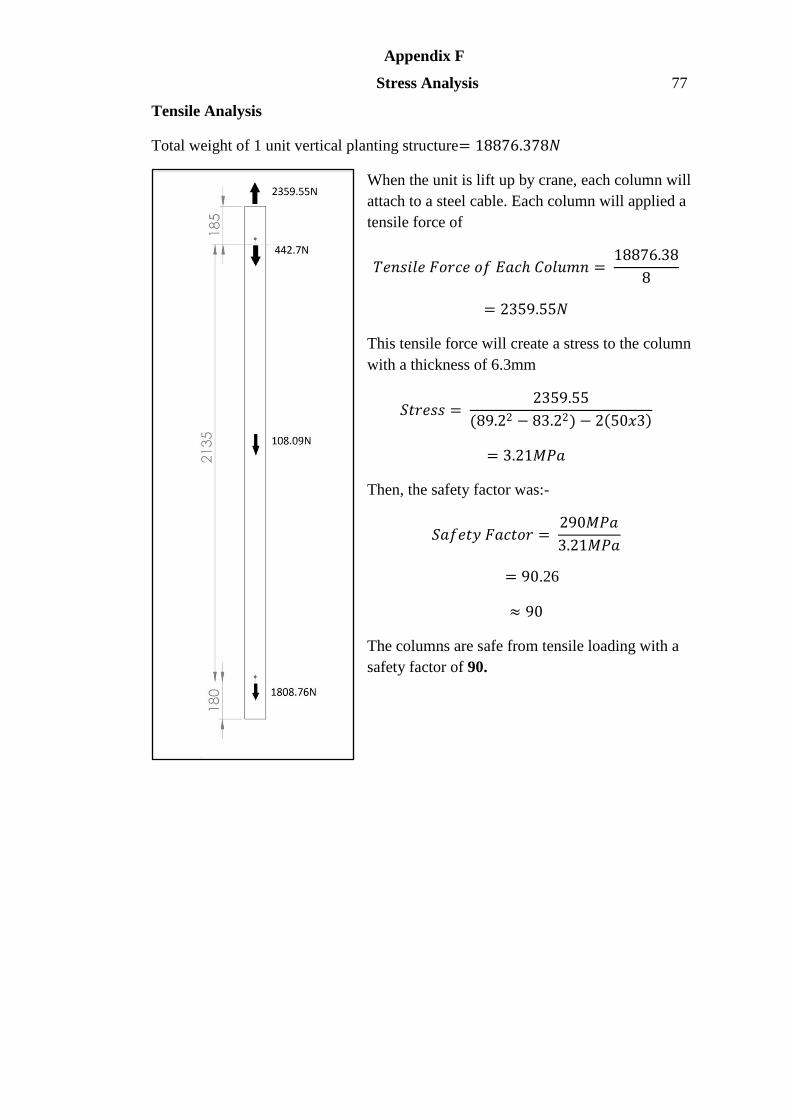
Appendix F
Stress Analysis 77
Tensile Analysis
Total weight of 1 unit vertical planting structure= 18876.378𝑁
When the unit is lift up by crane, each column will
attach to a steel cable. Each column will applied a
tensile force of
𝑇𝑒𝑛𝑠𝑖𝑙𝑒 𝐹𝑜𝑟𝑐𝑒 𝑜𝑓 𝐸𝑎𝑐 𝐶𝑜𝑙𝑢𝑚𝑛 = 18876.38
8
= 2359.55𝑁
This tensile force will create a stress to the column
with a thickness of 6.3mm
𝑆𝑡𝑟𝑒𝑠𝑠 = 2359.55
(89.22 − 83.22) − 2 50𝑥3
= 3.21𝑀𝑃𝑎
Then, the safety factor was:-
𝑆𝑎𝑓𝑒𝑡𝑦 𝐹𝑎𝑐𝑡𝑜𝑟 = 290𝑀𝑃𝑎
3.21𝑀𝑃𝑎
= 90.26
≈ 90
The columns are safe from tensile loading with a
safety factor of 90.
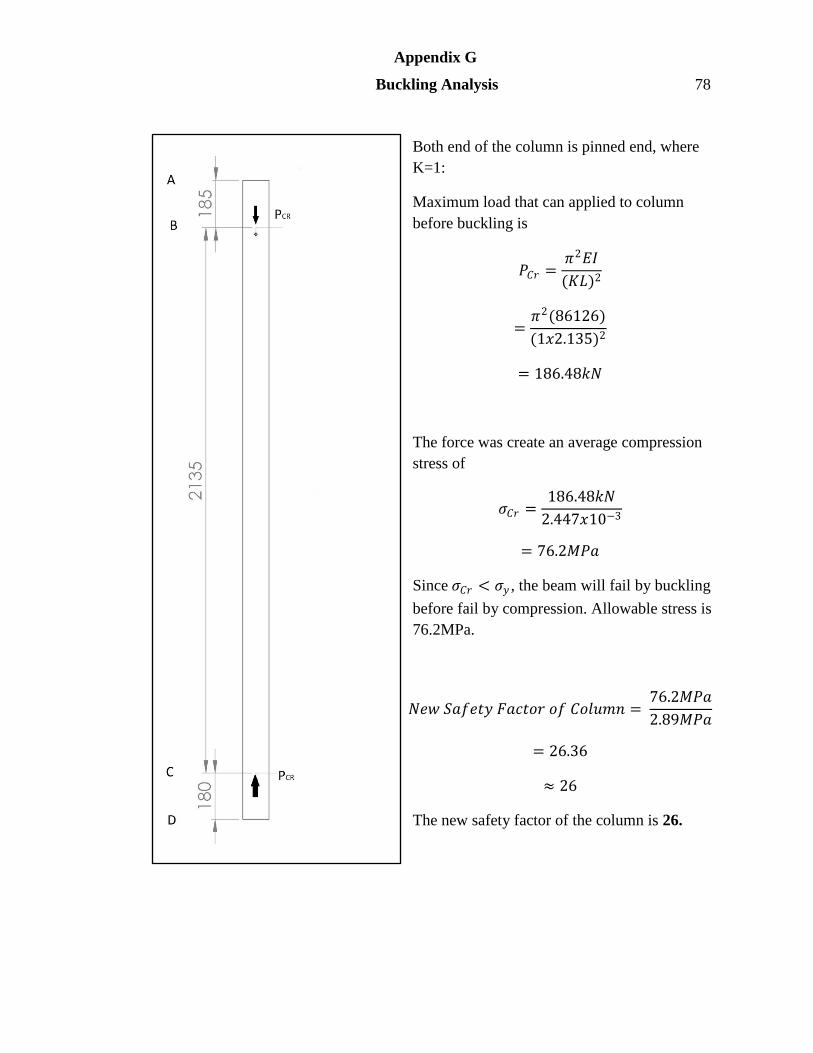
Appendix G
Buckling Analysis 78
Both end of the column is pinned end, where
K=1:
Maximum load that can applied to column
before buckling is
𝑃𝐶𝑟 =𝜋2𝐸𝐼
(𝐾𝐿)2
=𝜋2(86126)
(1𝑥2.135)2
= 186.48𝑘𝑁
The force was create an average compression
stress of
𝜎𝐶𝑟 =186.48𝑘𝑁
2.447𝑥10−3
= 76.2𝑀𝑃𝑎
Since 𝜎𝐶𝑟 < 𝜎𝑦 , the beam will fail by buckling
before fail by compression. Allowable stress is
76.2MPa.
𝑁𝑒𝑤 𝑆𝑎𝑓𝑒𝑡𝑦 𝐹𝑎𝑐𝑡𝑜𝑟 𝑜𝑓 𝐶𝑜𝑙𝑢𝑚𝑛 = 76.2𝑀𝑃𝑎
2.89𝑀𝑃𝑎
= 26.36
≈ 26
The new safety factor of the column is 26.
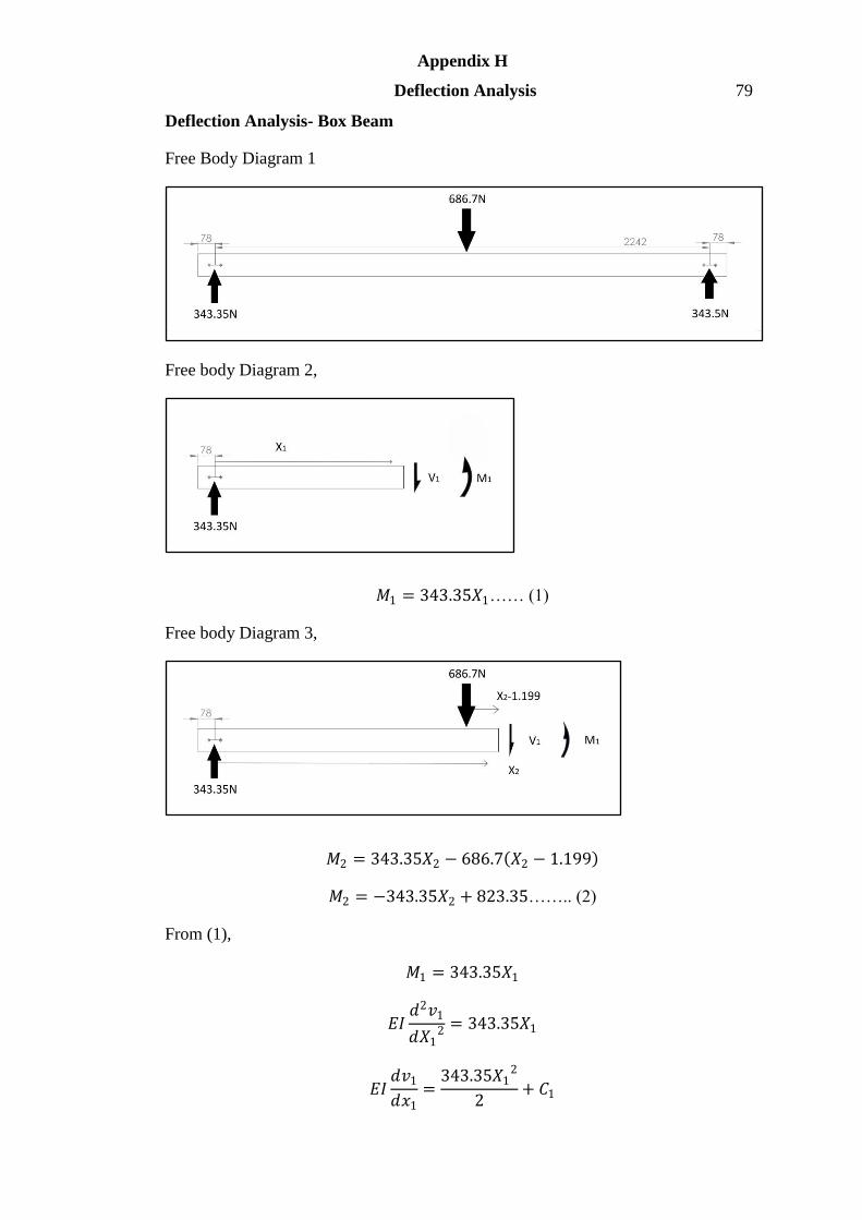
Appendix H
Deflection Analysis 79
Deflection Analysis- Box Beam
Free Body Diagram 1
Free body Diagram 2,
𝑀1 = 343.35𝑋1…… (1)
Free body Diagram 3,
𝑀2 = 343.35𝑋2 − 686.7 𝑋2 − 1.199
𝑀2 = −343.35𝑋2 + 823.35…….. (2)
From (1),
𝑀1 = 343.35𝑋1
𝐸𝐼𝑑2𝑣1
𝑑𝑋12 = 343.35𝑋1
𝐸𝐼𝑑𝑣1
𝑑𝑥1=
343.35𝑋12
2+ 𝐶1
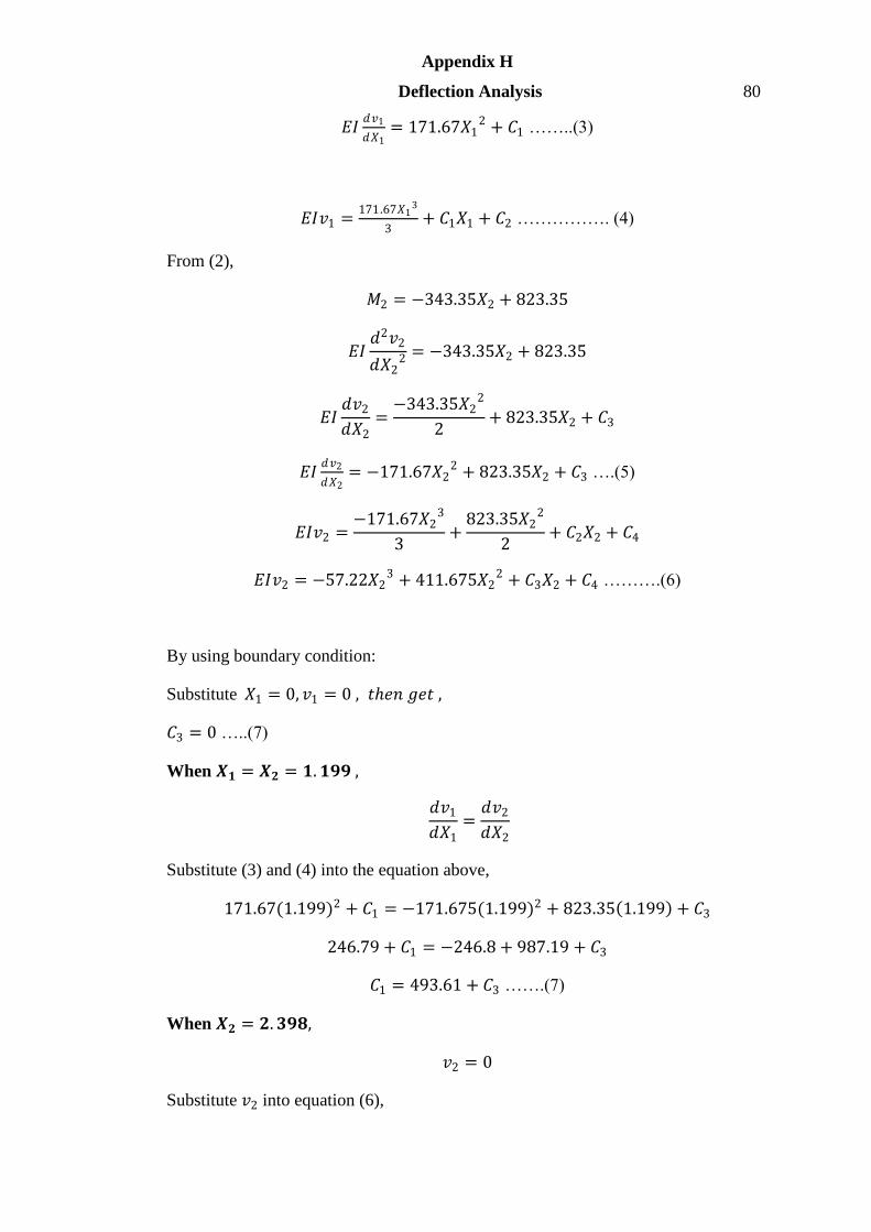
Appendix H
Deflection Analysis 80
𝐸𝐼𝑑𝑣1
𝑑𝑋1= 171.67𝑋1
2 + 𝐶1 ……..(3)
𝐸𝐼𝑣1 =171.67𝑋1
3
3+ 𝐶1𝑋1 + 𝐶2 ……………. (4)
From (2),
𝑀2 = −343.35𝑋2 + 823.35
𝐸𝐼𝑑2𝑣2
𝑑𝑋22 = −343.35𝑋2 + 823.35
𝐸𝐼𝑑𝑣2
𝑑𝑋2=
−343.35𝑋22
2+ 823.35𝑋2 + 𝐶3
𝐸𝐼𝑑𝑣2
𝑑𝑋2= −171.67𝑋2
2 + 823.35𝑋2 + 𝐶3 ….(5)
𝐸𝐼𝑣2 =−171.67𝑋2
3
3+
823.35𝑋22
2+ 𝐶2𝑋2 + 𝐶4
𝐸𝐼𝑣2 = −57.22𝑋23 + 411.675𝑋2
2 + 𝐶3𝑋2 + 𝐶4 ……….(6)
By using boundary condition:
Substitute 𝑋1 = 0, 𝑣1 = 0 , 𝑡𝑒𝑛 𝑔𝑒𝑡 ,
𝐶3 = 0 …..(7)
When 𝑿𝟏 = 𝑿𝟐 = 𝟏. 𝟏𝟗𝟗 ,
𝑑𝑣1
𝑑𝑋1=
𝑑𝑣2
𝑑𝑋2
Substitute (3) and (4) into the equation above,
171.67(1.199)2 + 𝐶1 = −171.675(1.199)2 + 823.35 1.199 + 𝐶3
246.79 + 𝐶1 = −246.8 + 987.19 + 𝐶3
𝐶1 = 493.61 + 𝐶3 …….(7)
When 𝑿𝟐 = 𝟐. 𝟑𝟗𝟖,
𝑣2 = 0
Substitute 𝑣2 into equation (6),

Appendix H
Deflection Analysis 81
0 = −57.225 2.398 3 + 411.675 2.398 2 + 𝐶3 2.398 + 𝐶4
0 = 1578.19 + 2.398𝐶3 + 𝐶4
𝐶4 = −1578.19 − 2.398𝐶3 …… (8)
When 𝑿𝟏 = 𝑿𝟐 = 𝟏. 𝟏𝟗𝟗,
𝑣1 = 𝑣2
Substitute (4) and (6) into above equation,
57.22 1.199 3 + 𝐶1 1.199
= −57.225 1.199 3 + 411.675 1.199 2 + 1.199𝐶3 + 𝐶4
98.63 + 1.199𝐶1 = −98.64 + 591.82 + 1.199𝐶3 + 𝐶4
Substitute (7) into the equation,
98.63 + 1.199 493.61 + 𝐶3
= −98.64 + 591.82 + 1.199𝐶3 − 1578.19 − 2.398𝐶3
98.63 + 591.84 + 1.199𝐶3 = 493.18 − 1578.79 − 1.199𝐶3
1777.08 = −2.398𝐶3
𝐶3 = −741.07 …..(9)
Substitute (9) into (7),
𝐶1 = 493.61 + −741.07
𝐶1 = −247.46
Substitute (9) into (8),
𝐶4 = −1578.19 − 2.398 −741.07
𝐶4 = 198.89
Thus,
𝑪𝟏 = −𝟐𝟒𝟕.𝟒𝟔 , 𝑪𝟐 = 𝟎 , 𝑪𝟑 = −𝟕𝟒𝟏.𝟎𝟕 , 𝑪𝟒 = 𝟏𝟗𝟖.𝟖𝟗
From (3),
𝐸𝐼𝑑𝑣1
𝑑𝑋1= 171.67𝑋1
2 − 247.46
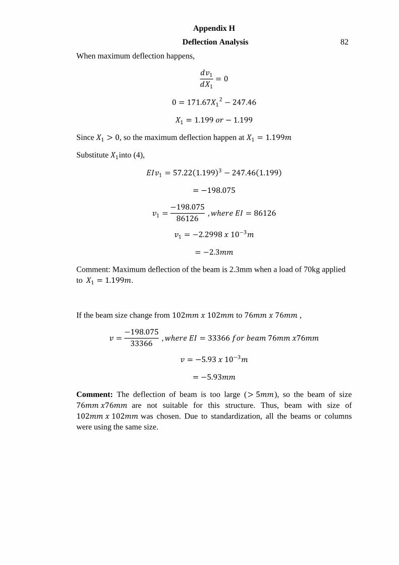
Appendix H
Deflection Analysis 82
When maximum deflection happens,
𝑑𝑣1
𝑑𝑋1= 0
0 = 171.67𝑋12 − 247.46
𝑋1 = 1.199 𝑜𝑟 − 1.199
Since 𝑋1 > 0, so the maximum deflection happen at 𝑋1 = 1.199𝑚
Substitute 𝑋1into (4),
𝐸𝐼𝑣1 = 57.22 1.199 3 − 247.46 1.199
= −198.075
𝑣1 =−198.075
86126 , 𝑤𝑒𝑟𝑒 𝐸𝐼 = 86126
𝑣1 = −2.2998 𝑥 10−3𝑚
= −2.3𝑚𝑚
Comment: Maximum deflection of the beam is 2.3mm when a load of 70kg applied
to 𝑋1 = 1.199𝑚.
If the beam size change from 102𝑚𝑚 𝑥 102𝑚𝑚 to 76𝑚𝑚 𝑥 76𝑚𝑚 ,
𝑣 =−198.075
33366 , 𝑤𝑒𝑟𝑒 𝐸𝐼 = 33366 𝑓𝑜𝑟 𝑏𝑒𝑎𝑚 76𝑚𝑚 𝑥76𝑚𝑚
𝑣 = −5.93 𝑥 10−3𝑚
= −5.93𝑚𝑚
Comment: The deflection of beam is too large (> 5𝑚𝑚), so the beam of size
76𝑚𝑚 𝑥76𝑚𝑚 are not suitable for this structure. Thus, beam with size of
102𝑚𝑚 𝑥 102𝑚𝑚 was chosen. Due to standardization, all the beams or columns
were using the same size.
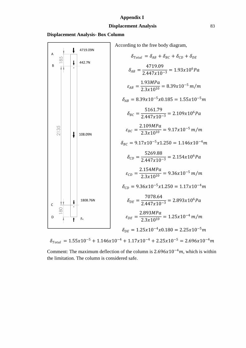
Appendix I
Displacement Analysis 83
Displacement Analysis- Box Column
According to the free body diagram,
𝛿𝑇𝑜𝑡𝑎𝑙 = 𝛿𝐴𝐵 + 𝛿𝐵𝐶 + 𝛿𝐶𝐷 + 𝛿𝐷𝐸
𝛿𝐴𝐵 =4719.09
2.447𝑥10−3= 1.93𝑥106𝑃𝑎
휀𝐴𝐵 =1.93𝑀𝑃𝑎
2.3𝑥1010= 8.39𝑥10−5 𝑚 𝑚
𝛿𝐴𝐵 = 8.39𝑥10−5𝑥0.185 = 1.55𝑥10−5𝑚
𝛿𝐵𝐶 =5161.79
2.447𝑥10−3= 2.109𝑥106𝑃𝑎
휀𝐵𝐶 =2.109𝑀𝑃𝑎
2.3𝑥1010= 9.17𝑥10−5 𝑚 𝑚
𝛿𝐵𝐶 = 9.17𝑥10−5𝑥1.250 = 1.146𝑥10−4𝑚
𝛿𝐶𝐷 =5269.88
2.447𝑥10−3= 2.154𝑥106𝑃𝑎
휀𝐶𝐷 =2.154𝑀𝑃𝑎
2.3𝑥1010= 9.36𝑥10−5 𝑚 𝑚
𝛿𝐶𝐷 = 9.36𝑥10−5𝑥1.250 = 1.17𝑥10−4𝑚
𝛿𝐷𝐸 =7078.64
2.447𝑥10−3= 2.893𝑥106𝑃𝑎
휀𝐷𝐸 =2.893𝑀𝑃𝑎
2.3𝑥1010= 1.25𝑥10−4 𝑚 𝑚
𝛿𝐷𝐸 = 1.25𝑥10−4𝑥0.180 = 2.25𝑥10−5𝑚
𝛿𝑇𝑜𝑡𝑎𝑙 = 1.55𝑥10−5 + 1.146𝑥10−4 + 1.17𝑥10−4 + 2.25𝑥10−5 = 2.696𝑥10−4𝑚
Comment: The maximum deflection of the column is 2.696𝑥10−4𝑚, which is within
the limitation. The column is considered safe.

Appendix J
Bolt Analysis 84
Total weight of for lower part of the structure is 15334.77N
This load was assumed distribute to 8 columns equally.
𝐿𝑜𝑎𝑑 𝑜𝑛 𝑒𝑎𝑐 𝑐𝑜𝑙𝑢𝑚𝑛 =15334.77
8= 1916.85𝑁
For Corner Joint 1,
↑ 𝑎𝑠 𝑝𝑜𝑠𝑖𝑡𝑖𝑣𝑒 ∑𝐹𝑦 = 0
0 = −479.21 − 479.21 + 𝐹1 + 𝐹2
𝐹1 + 𝐹2 = 958.42𝑁 , 𝐹1 = 𝐹2
= 479.21𝑁
From Free Body Diagram,
𝑟𝐴 = 74.18 , 𝑟𝐵 = 111.92
𝑟𝑐 = 111.92 , 𝑟𝐷 = 74.18
𝑐𝑙𝑜𝑐𝑘𝑤𝑖𝑠𝑒 𝑎𝑠 𝑝𝑜𝑠𝑖𝑡𝑖𝑣𝑒 ∑𝑀 = 0
0 = −479.21 0.09353 − 479.21 0.04153 − 479.21 0.06147 𝑥 2 + 𝑀𝐺
𝑀𝐺 = 123.64𝑁𝑚
This moment will give secondary shear to the bolt.
𝑀𝐺 = 𝐹𝐴"rA+FB"𝑟𝐵 + 𝐹𝐶"𝑟𝐶 + 𝐹𝐷"𝑟𝐷
123.64 = 𝐹𝐴"(0.07418)+FB"(0.1119)+FC"(0.1119)+FD" 0.07418 ……..(1)
Given,
𝐹𝐴"
𝑟𝐴=
𝐹𝐵"
𝑟𝐵
0.119𝐹𝐴"=0.07418FB"
𝐹𝐴" = 0.663𝐹𝐵"
Substitute 𝐹𝐴" into (1),
123.64 = 0.14836(0.663𝐹𝐵") + 0.2238𝐹𝐵"
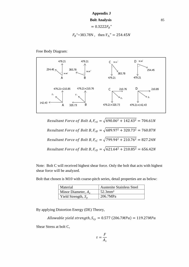
Appendix J
Bolt Analysis 85
= 0.3222𝐹𝐵"
𝐹𝐵"=383.78N , then FA" = 254.45𝑁
Free Body Diagram:
𝑅𝑒𝑠𝑢𝑙𝑡𝑎𝑛𝑡 𝐹𝑜𝑟𝑐𝑒 𝑜𝑓 𝐵𝑜𝑙𝑡 𝐴, 𝐹𝑟𝐴 = 690.062 + 142.432 = 704.61𝑁
𝑅𝑒𝑠𝑢𝑙𝑡𝑎𝑛𝑡 𝐹𝑜𝑟𝑐𝑒 𝑜𝑓 𝐵𝑜𝑙𝑡 𝐵, 𝐹𝑟𝐵 = 689.972 + 320.732 = 760.87𝑁
𝑅𝑒𝑠𝑢𝑙𝑡𝑎𝑛𝑡 𝐹𝑜𝑟𝑐𝑒 𝑜𝑓 𝐵𝑜𝑙𝑡 𝐵, 𝐹𝑟𝐶 = 799.942 + 210.762 = 827.24𝑁
𝑅𝑒𝑠𝑢𝑙𝑡𝑎𝑛𝑡 𝐹𝑜𝑟𝑐𝑒 𝑜𝑓 𝐵𝑜𝑙𝑡 𝐵, 𝐹𝑟𝐷 = 621.642 + 210.852 = 656.42𝑁
Note: Bolt C will received highest shear force. Only the bolt that acts with highest
shear force will be analyzed.
Bolt that chosen is M10 with coarse-pitch series, detail properties are as below:
Material Austenite Stainless Steel
Minor Diameter, 𝐴𝑠 52.3mm²
Yield Strength, 𝑆𝑦 206.7MPa
By applying Distortion Energy (DE) Theory,
𝐴𝑙𝑙𝑜𝑤𝑎𝑏𝑙𝑒 𝑦𝑖𝑒𝑙𝑑 𝑠𝑡𝑟𝑒𝑛𝑔𝑡, 𝑆𝑠𝑦 = 0.577 206.7𝑀𝑃𝑎 = 119.27𝑀𝑃𝑎
Shear Stress at bolt C,
𝜏 =𝐹
𝐴𝑠
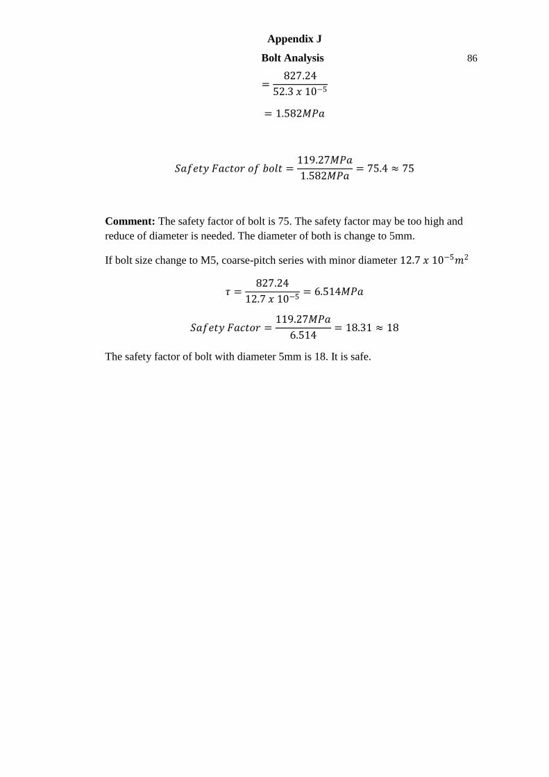
Appendix J
Bolt Analysis 86
=827.24
52.3 𝑥 10−5
= 1.582𝑀𝑃𝑎
𝑆𝑎𝑓𝑒𝑡𝑦 𝐹𝑎𝑐𝑡𝑜𝑟 𝑜𝑓 𝑏𝑜𝑙𝑡 =119.27𝑀𝑃𝑎
1.582𝑀𝑃𝑎= 75.4 ≈ 75
Comment: The safety factor of bolt is 75. The safety factor may be too high and
reduce of diameter is needed. The diameter of both is change to 5mm.
If bolt size change to M5, coarse-pitch series with minor diameter 12.7 𝑥 10−5𝑚2
𝜏 =827.24
12.7 𝑥 10−5= 6.514𝑀𝑃𝑎
𝑆𝑎𝑓𝑒𝑡𝑦 𝐹𝑎𝑐𝑡𝑜𝑟 =119.27𝑀𝑃𝑎
6.514= 18.31 ≈ 18
The safety factor of bolt with diameter 5mm is 18. It is safe.
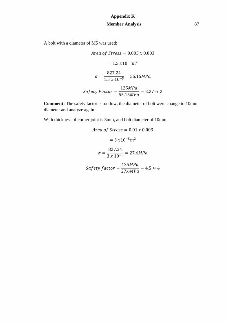
Appendix K
Member Analysis 87
A bolt with a diameter of M5 was used:
𝐴𝑟𝑒𝑎 𝑜𝑓 𝑆𝑡𝑟𝑒𝑠𝑠 = 0.005 𝑥 0.003
= 1.5 𝑥10−5𝑚2
𝜎 =827.24
1.5 𝑥 10−5= 55.15𝑀𝑃𝑎
𝑆𝑎𝑓𝑒𝑡𝑦 𝐹𝑎𝑐𝑡𝑜𝑟 =125𝑀𝑃𝑎
55.15𝑀𝑃𝑎= 2.27 ≈ 2
Comment: The safety factor is too low, the diameter of bolt were change to 10mm
diameter and analyze again.
With thickness of corner joint is 3mm, and bolt diameter of 10mm,
𝐴𝑟𝑒𝑎 𝑜𝑓 𝑆𝑡𝑟𝑒𝑠𝑠 = 0.01 𝑥 0.003
= 3 𝑥10−5𝑚2
𝜎 =827.24
3 𝑥 10−5= 27.6𝑀𝑃𝑎
𝑆𝑎𝑓𝑒𝑡𝑦 𝑓𝑎𝑐𝑡𝑜𝑟 =125𝑀𝑃𝑎
27.6𝑀𝑃𝑎= 4.5 ≈ 4
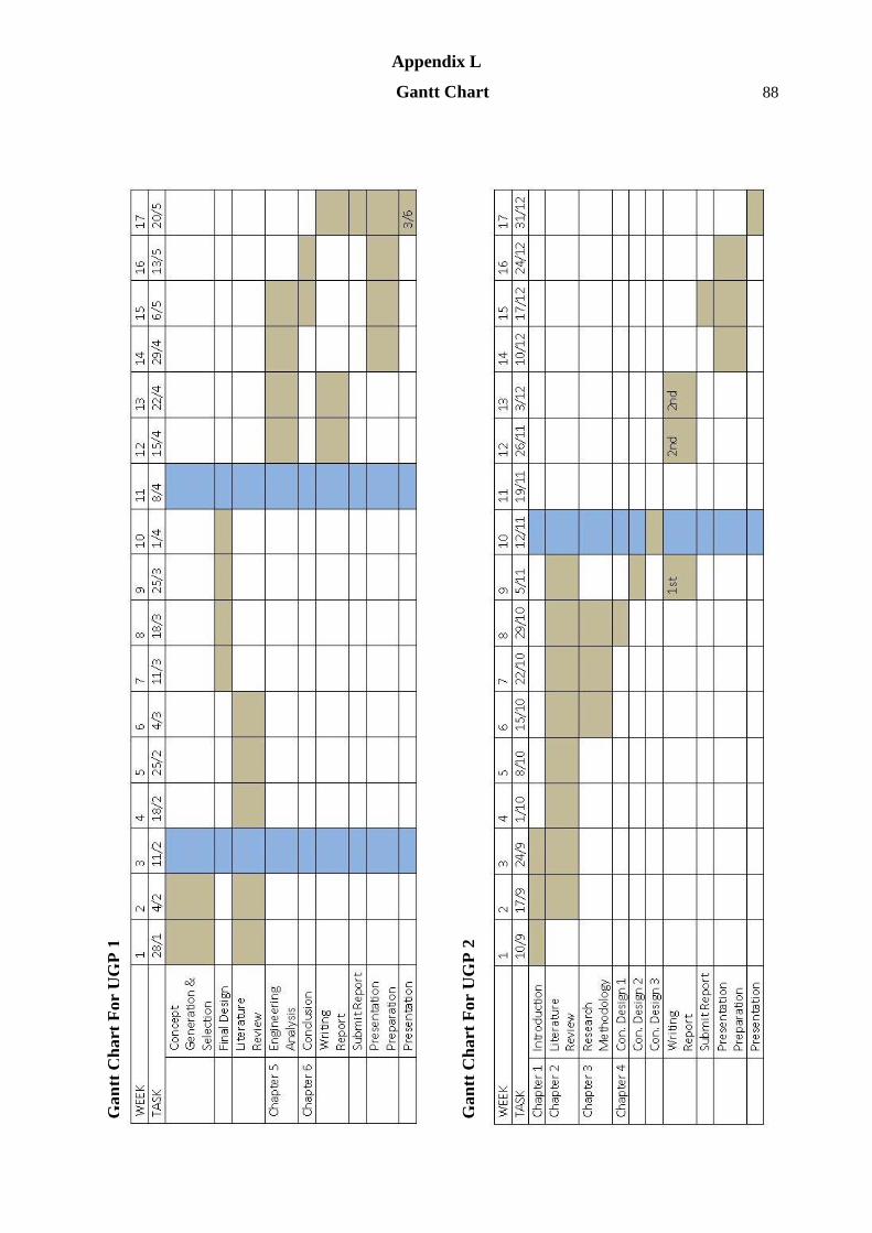
Appendix L
Gantt Chart 88
G
an
tt C
ha
rt F
or
UG
P 1
Gan
tt C
ha
rt F
or
UG
P 2